radiological evaluation of tubes, lines, drains, and other
TRANSCRIPT

Radiographic Assessment of Tubes, Lines, Drains, and Other Devices - Normal
Placement, Positioning Errors, Complications, and Indications for
Radiological EvaluationKevin Kalisz
8/1/2017

Outline
• Endotracheal tubes
• Tracheostomy tubes
• Central venous catheters
• PA catheters
• Chest tubes
• Enteric tubes
• Cardiac pacemakers/defibrillators
1. Normal position
2. Abnormal position/complications
3. Indications of radiographic evaluation

Endotracheal Tubes – Normal Position
• Gold standard for determining placement in airway is end-tidal CO2
*
• Limited ability to detect some complications • Physical exam maneuvers also may be
helpful
• Radiographic assessment of tube position based on visualizing radio-opaque line on ETT
*In patients with adequate tissue perfusion

Endotracheal Tubes – Normal Position
• ETT position dependent on neck flexion and extension:• Neck flexion (mandible @ T1-2): ETT tip can descend up to 2 cm
• Neck extension (mandible @ C4): ETT tip can ascend up to 2 cm
• Acceptable positioning:• Proximal tube tip: level of medial heads of the clavicle
• Too proximal – risk upper airway/vocal cord injury
• Distal tube tip: 2 cm above carina• Too distal – mainstem bronchus intubation with neck flexion
• Tracheal cuff should fill tracheal wall (not bulge)

Endotracheal Tubes – Normal Position

Endotracheal Tubes – Normal Position

Endotracheal Tubes – Abnormal Position
• Potential Complications:• Increased risk of spontaneous
extubation
• Aspiration
• Vocal cord injury
• Gastric distension
Proximal ETT position

Endotracheal Tubes – Abnormal Position

Endotracheal Tubes – Abnormal Position
• Potential Complications:• Left lobe (R main stem bronchus)
or right upper lobe (R inferior intermediate bronchus) collapse/atelectasis
• Tension pneumothorax
*Right main stem bronchus intubation is most common positioning error
Uncomplicated right main stem bronchus intubation

Endotracheal Tubes – Complications

Endotracheal Tubes – Complications
Right main stem bronchus intubation with left lung collapse (thin black arrows)
4:02 AM 4:23 AM

Endotracheal Tubes – Complications
Esophageal intubation with marked gastric distension

Endotracheal Tubes – Indications for Studies
• ACR Appropriateness Criteria
• Rating scale:• 1-3: Usually not appropriate
• 4-6: May be appropriate
• 7-9: Usually appropriate
• Takes into account clinical usefulness and potential costs/harms (i.e. radiation dose, etc.)

Endotracheal Tubes – Indications for Studies
• Radiographic evaluation indicated:• After ETT insertion (appropriateness score = 9)
• Higher rate of detecting malpositioned tubes with chest xrays than physical exam
• Patient with ETT in place – clinical indications only (9)
• Radiographic evaluation NOT indicated:• Daily, routine follow-up (3)
• Minimal benefit in cardiothoracic patients(?)
Legend: 1-3: usually not appropriate; 4-6: may be appropriate; 7-9: usually appropriate

Tracheostomy Tubes – Normal Position
• Similar distal tip positioning rules as ETTs
• Tip position should NOT vary with neck flexion/extension
• At least 2/3 of “smooth” portion should lie within the trachea
“Smooth” portion

Tracheostomy Tubes – Normal Position

Tracheostomy Tubes – Normal Position

Tracheostomy Tubes – Complications
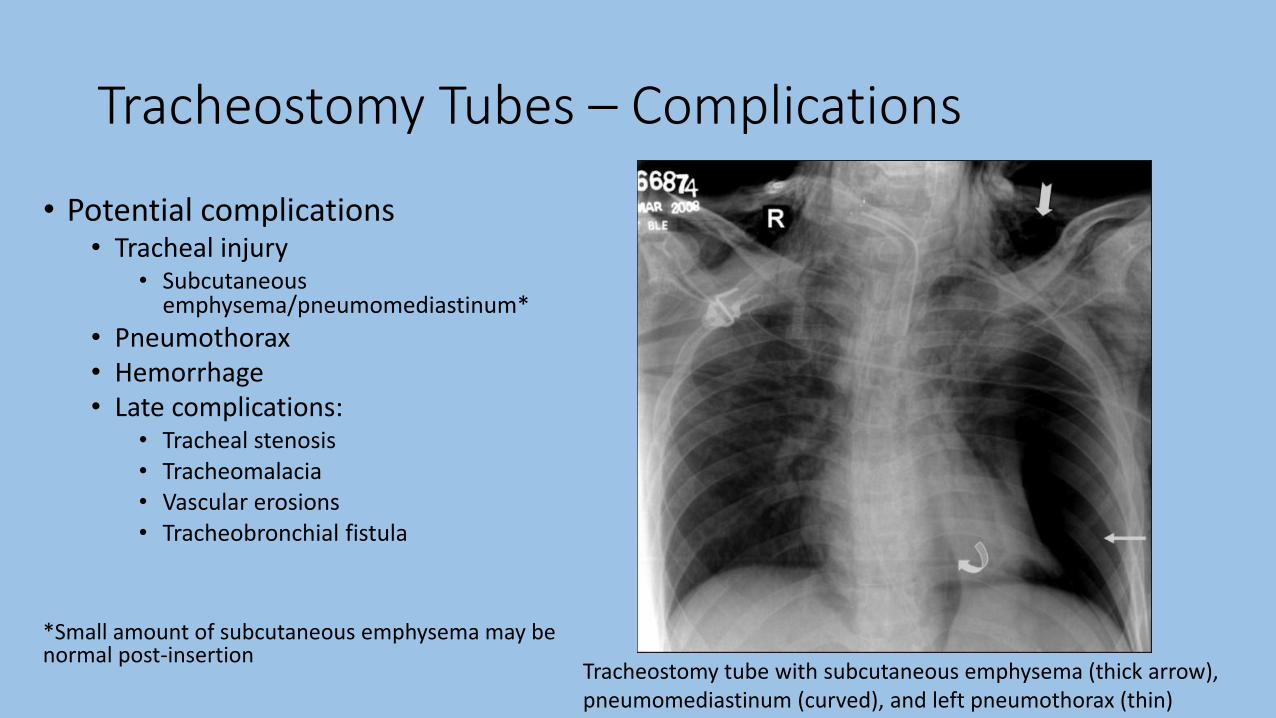
Tracheostomy Tubes – Complications
• Potential complications• Tracheal injury
• Subcutaneous emphysema/pneumomediastinum*
• Pneumothorax• Hemorrhage• Late complications:
• Tracheal stenosis• Tracheomalacia• Vascular erosions• Tracheobronchial fistula
*Small amount of subcutaneous emphysema may be normal post-insertion
Tracheostomy tube with subcutaneous emphysema (thick arrow), pneumomediastinum (curved), and left pneumothorax (thin)

Central Venous Catheters – Normal Position
• Central venous catheter may be central (IJ, subclavian) or peripheral (PICC)
• Catheter tip should terminate in SVC or cavo-atrial junction • “OK to use” varies with intended function
• Placement borders:• Brachiocephalic/IJ junction – 1st anterior
intercostal space• Last venous valve
• Cavo-atrial junction – inferior border of right bronchus intermedius (+2.5 cm below)• Prevent cardiac chamber insertion

Central Venous Catheters – Normal Position
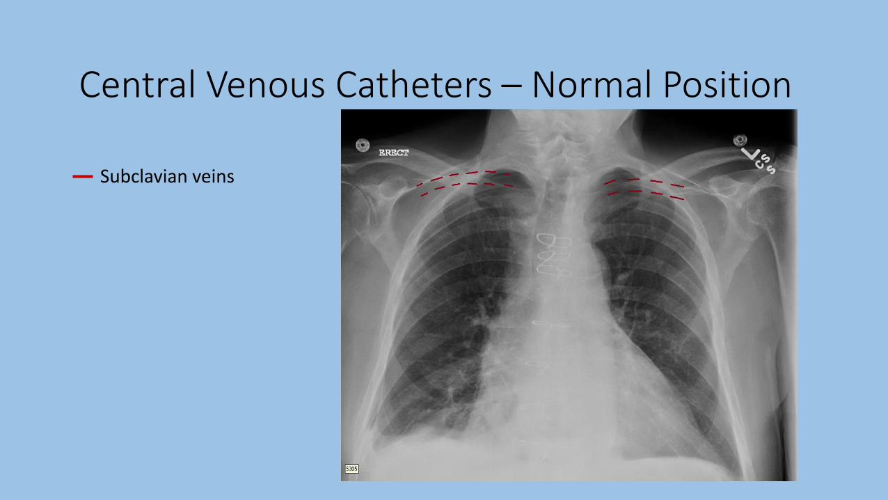
Central Venous Catheters – Normal Position
Subclavian veins

Central Venous Catheters – Normal Position
Subclavian veins
Internal jugular veins

Central Venous Catheters – Normal Position
Subclavian veins
Internal jugular veins
Brachiocephalic veins

Central Venous Catheters – Normal Position
Subclavian veins
Internal jugular veins
Brachiocephalic veins
Superior vena cava

Central Venous Catheters – Normal Position
Subclavian veins
Internal jugular veins
Brachiocephalic veins
Superior vena cava
Right atrium
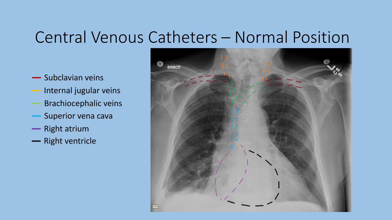
Central Venous Catheters – Normal Position
Subclavian veins
Internal jugular veins
Brachiocephalic veins
Superior vena cava
Right atrium
Right ventricle

Central Venous Catheters – Normal Position

Central Venous Catheters – Normal Position

Central Venous Catheters – Abnormal Position
• Positioning errors:• Ipsilateral IJ
• Contralateral brachiocephalic vein
• Right atrium/ventricle• Increased risk of arrhythmias
• Reduced dilution of administered medications
• Azygous vein*
• Internal thoracic vein*
*Difficult to detect on routine AP imaging –may require lateral imaging if suspicious

Central Venous Catheters – Abnormal Position
• Positioning errors:• Ipsilateral IJ vein
• Contralateral brachiocephalic vein
• Right atrium/ventricle• Increased risk of arrhythmias
• Reduced dilution of administered medications
• Azygous vein*
• Internal thoracic vein*
*Difficult to detect on routine AP imaging –may require lateral imaging if suspicious
Left subclavian line terminating in left IJ

Central Venous Catheters – Abnormal Position
• Positioning errors:• Ipsilateral IJ vein
• Contralateral brachiocephalic vein
• Right atrium/ventricle• Increased risk of arrhythmias
• Reduced dilution of administered medications
• Azygous vein*
• Internal thoracic vein*
*Difficult to detect on routine AP imaging –may require lateral imaging if suspicious
Right subclavian line terminating in left brachiocephalic

Central Venous Catheters – Abnormal Position
• Positioning errors:• Ipsilateral IJ • Contralateral brachiocephalic
vein• Right atrium/ventricle
• Increased risk of arrhythmias• Reduced dilution of
administered medications
• Azygous vein*• Internal thoracic vein*
*Difficult to detect on routine AP imaging –may require lateral imaging if suspicious; more common in SVC thrombus and/or volume overload Right arm PICC terminating in right atrium
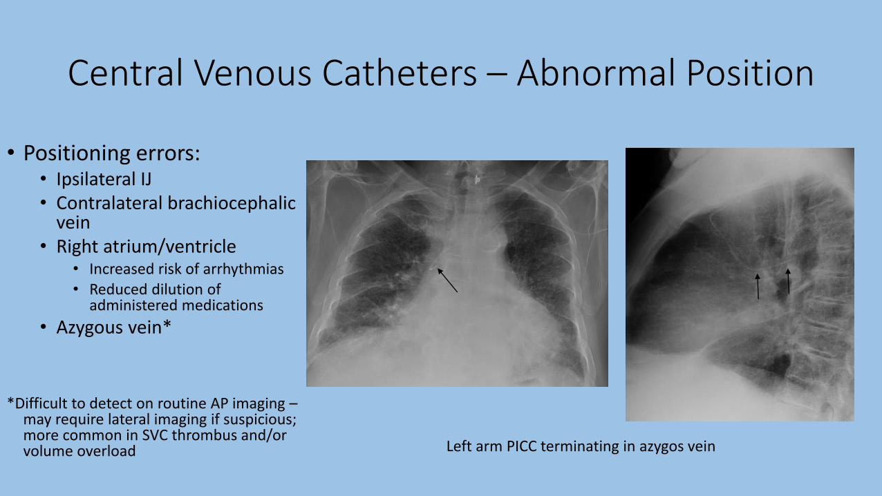
Central Venous Catheters – Abnormal Position
• Positioning errors:• Ipsilateral IJ • Contralateral brachiocephalic
vein• Right atrium/ventricle
• Increased risk of arrhythmias• Reduced dilution of
administered medications
• Azygous vein*• Internal thoracic vein*
*Difficult to detect on routine AP imaging –may require lateral imaging if suspicious; more common in SVC thrombus and/or volume overload Left arm PICC terminating in azygos vein

Central Venous Catheters – Abnormal Position
• Positioning errors:• Ipsilateral IJ• Contralateral brachiocephalic
vein• Right atrium/ventricle
• Increased risk of arrhythmias• Reduced dilution of
administered medications
• Azygous vein*• Internal thoracic vein*
*Difficult to detect on routine AP imaging –may require lateral imaging if suspicious; more common in SVC thrombus and/or volume overload Left arm PICC terminating in azygos vein

Central Venous Catheters – Anatomic Variants
• Anatomic variants :• Persistent left SVC (0.3% of
population)• Left SVC → coronary sinus → RA
• More common in CHD
• Ventricular septal defect
• Atrial septal defect
• Anomalous pulmonary vein
Left IJ catheter terminating within proximal left-sided SVC

• Anatomic variants :• Persistent left SVC (0.3% of
population)• Left SVC → coronary sinus → RA
• More common in CHD
• Ventricular septal defect
• Atrial septal defect
• Anomalous pulmonary vein
Left IJ catheter terminating within proximal left-sided SVC
Central Venous Catheters – Anatomic Variants

Central Venous Catheters – Complications

Central Venous Catheters – Complications
Left subclavian line with tip in SVC; Left pneumothorax

Central Venous Catheters – Complications

Central Venous Catheters – Complications
Right IJ catheter with venous perforation and right mediastinal hematoma
• Signs of perforation:• Unusual catheter trajectory
• New apical density (“apical cap”)• Extrapleural hematoma
• New pleural effusion • Hemothorax
• Mediastinal widening• Mediastinal hematoma

Central Venous Catheters – Complications
Central line placement into left common carotid artery

Central Venous Catheters– Indications for Studies
• Radiographic evaluation indicated:• After CVC insertion (appropriateness score = 9)
• Patient with CVC in place – clinical indications only (9)
• Radiographic evaluation NOT indicated:• Daily, routine follow-up (1)
• Radiographic evaluation after failed CVC insertion?• Insertion site hematoma, pneumothorax
• No clear evidence or guidelines
Legend: 1-3: usually not appropriate; 4-6: may be appropriate; 7-9: usually appropriate

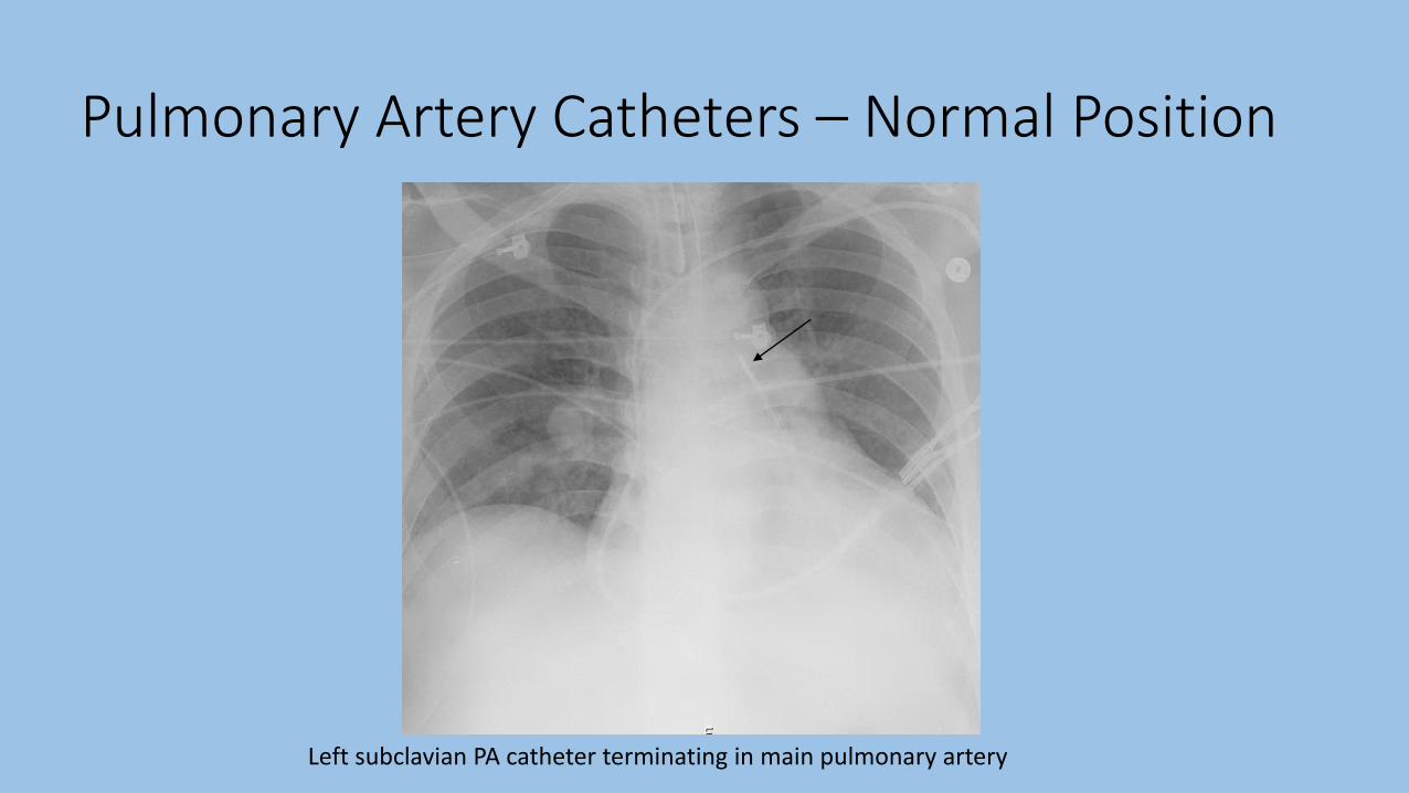
Pulmonary Artery Catheters – Normal Position
• Inserted via subclavian, jugular, or femoral veins
• “Resting” position dependent on its intended function• RV, pulmonary trunk, right/left PA, etc
• Ideal catheter tip position no farther than proximal interlobar pulmonary arteries• Within 1-2 cm of hilum/mediastinal
shadow
*Catheter balloon tip should only be inflated during pressure measurements!
Interlobar pulmonary arteries
Pulmonary Artery Catheters – Normal Position
Left subclavian PA catheter terminating in main pulmonary artery

Pulmonary Artery Catheters – Complications

Pulmonary Artery Catheters – Complications
Right IJ PA catheter (straight arrows) distally placed with pulmonary infarction (curved)
• Potential Complications:• Pulmonary artery infarction
• Tip too distal
• Persistent balloon inflation
• Clot around distal catheter tip
• Pulmonary artery rupture
• Pulmonary artery dissection
• Complications of CVCs• Looping/coiling
• Pneumothorax
• Hematoma
• Perforation

Pulmonary Artery Catheters – Complications• Potential Complications:
• Pulmonary artery infarction• Tip too distal
• Persistent balloon inflation
• Clot around distal catheter tip
• Pulmonary artery rupture
• Pulmonary artery dissection
• Complications of CVCs• Looping/coiling
• Pneumothorax
• Hematoma
• Perforation
Right IJ PA catheter (straight arrows) distally placed with pulmonary infarction (curved)

Pulmonary Artery Catheters– Indications for Studies
• Radiographic evaluation indicated:• After PAC insertion (appropriateness score = 9)
• Characteristic pressure tracings alone are NOT sufficient to verify position
• Patient with PAC in place – clinical indications only (9)
• Radiographic evaluation NOT indicated:• Daily, routine follow-up (1)
Legend: 1-3: usually not appropriate; 4-6: may be appropriate; 7-9: usually appropriate

Chest Tubes – Normal Position
Radiopaque line
Side holes
• Assessment based on identification of radiopaque lines and side holes
• All side holes must be within pleural space and completely visualized• Side holes = interruption of radiopaque line• Position medial to inner margin of ribs
• Tube direction depends on indication:• Air removal (PTX) – anterior and superior• Fluid removal (effusion)– posterior and inferior
• Tube should not “float” on top of effusion
• Lateral films also helpful in confirming position (i.e. anterior-posterior)• Non-contrast CT scan if still uncertain

Chest Tubes – Normal Position
Right apical chest tube Bilateral pigtail chest tubes

Chest Tubes – Abnormal Position
Incomplete tube placement with subcutaneous emphysema
• Positioning errors:• Incomplete insertion
• Side hole outside of pleural cavity
• Tube kinking• Tube angulations
• Tube kinking• Soft tissues/chest wall*• Lung fissures*
• Poor drainage• Horizontal projection• Herniation into tube → infarction
• Mediastinum (rare)• Abdomen (rare)
• Liver, spleen, stomach
*May appear normal on AP imaging
May require lateral imaging or CT (non-
contrast)
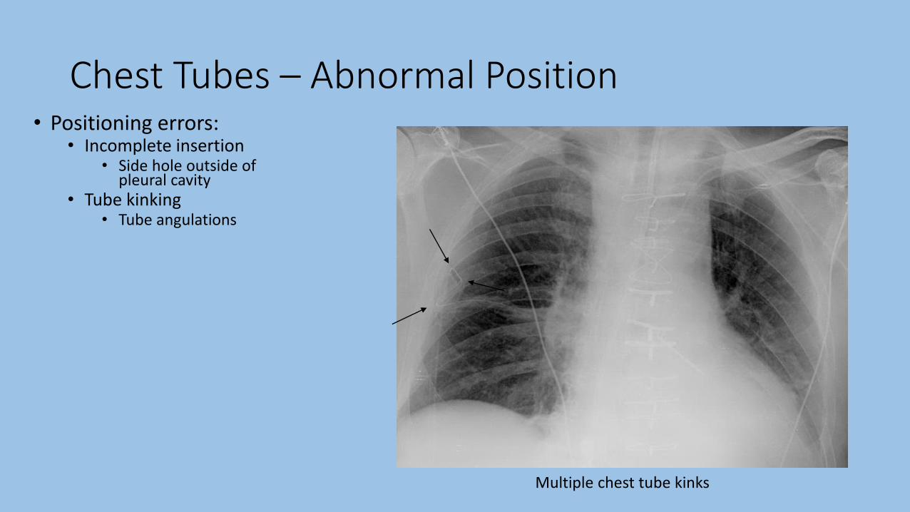
Chest Tubes – Abnormal Position
Multiple chest tube kinks
• Positioning errors:• Incomplete insertion
• Side hole outside of pleural cavity
• Tube kinking• Tube angulations
• Tube kinking• Soft tissues/chest wall*• Lung fissures*
• Poor drainage• Horizontal projection• Herniation into tube → infarction
• Mediastinum (rare)• Abdomen (rare)
• Liver, spleen, stomach
*May appear normal on AP imaging
May require lateral imaging or CT (non-
contrast)

Chest Tubes – Abnormal Position
Left chest tube appears in proper position
CT demonstrating chest tube within chest wall
• Positioning errors:• Incomplete insertion
• Side hole outside of pleural cavity
• Tube kinking• Tube angulations
• Soft tissue/chest wall• e kinking• Soft tissues/chest wall*• Lung fissures*
• Poor drainage• Horizontal projection• Herniation into tube → infarction
• Mediastinum (rare)• Abdomen (rare)
• Liver, spleen, stomach
*May appear normal on AP imaging
May require lateral imaging or CT (non-
contrast)
Chest Tubes – Abnormal Position• Positioning errors:
• Incomplete insertion• Side hole outside of
pleural cavity• Tube kinking
• Tube angulations• Soft tissue/chest wall• Lung fissures*
• Poor drainage• Horizontal projection• Herniation into tube →
infarction• Mediastinum (rare)• Abdomen (rare)
• Liver, spleen, stomach
*May appear normal on AP imaging
May require lateral imaging or CT (non-
contrast)
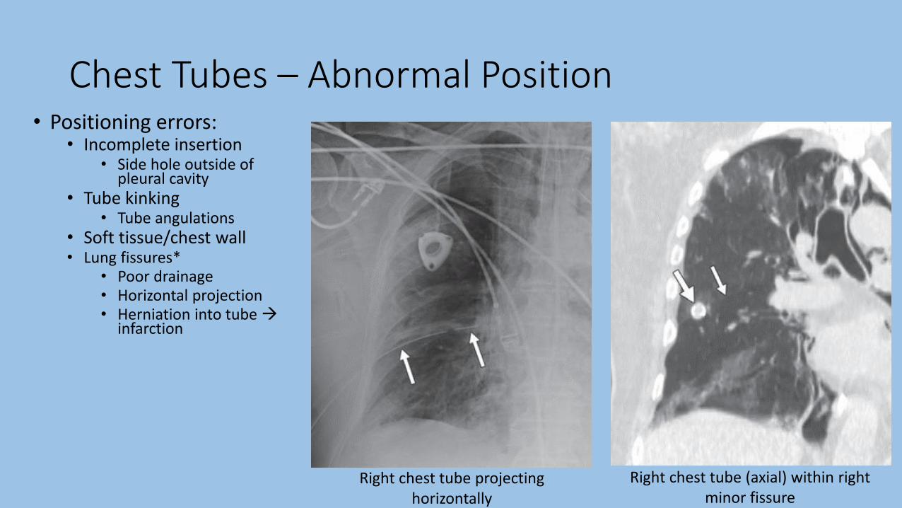
Right chest tube projecting horizontally
Right chest tube (axial) within right minor fissure

Chest Tubes – Abnormal Position
Right chest tube projecting horizontally
Right chest tube (axial) within right minor fissure
• Positioning errors:• Incomplete insertion
• Side hole outside of pleural cavity
• Tube kinking• Tube angulations
• Soft tissue/chest wall
• Lung fissures*• Poor drainage
• Horizontal projection
• Herniation into tube →infarction
*May appear normal on frontal chest X ray

Chest Tubes – Complications• Reexpansion
pulmonary edema• Rapid removal of
air/fluid from pleural space• Prolonged atelectasis
• Also: s/p thoracentesis
• Clinical manifestations:• <2 hours after lung
reexpansion
• Hypoxia → respiratory distress
• Lasts 1-2 days
• Unilateral airspace opacity
Right pleural effusion prior to drainage Interval resolution of right pleural effusion; new airspace opacity in RLL

Chest Tubes– Indications for Studies
• Radiographic evaluation indicated:• After chest tube insertion (appropriateness score = 9)
• Patient with chest tube in place – clinical indications only (9)• Also: newly malfunctioning chest tubes
• Radiographic evaluation NOT indicated:• Daily, routine follow-up (1)
Legend: 1-3: usually not appropriate; 4-6: may be appropriate; 7-9: usually appropriate

Enteric Tubes – Normal Position
• NGT/OGT• Larger diameter
• Stiffer
• Used for feeding or suction
• More easily placed
• Increased aspiration risk• Large feeding volumes
• Impaired gastric motility
• May measure gastric residuals
• May contain side holes
• Flexible/Dobhoff tube (DHT)• Small diameter
• More flexible
• Used for feeding only (no suction)
• More difficult to place• Weight (radiopaque) tip
• Decreased aspiration risk• Antral/post-pyloric placement
• May contain side holes

Enteric Tubes – Normal Position
• Optimal position depends on tube type• NGT/OGT:
• Feeding – distal/antral stomach placement• Tip directed towards midline • Tip at least 10cm distal to GE junction
• GE junction - just below level of the left cardiophrenic angle
• Decompression – gastric placement • Tip distal to GE junction
• Dobhoff:• Feeding – 2nd portion of duodenum
• Tip crosses midline; tip oriented caudally
• “Optimal” position ≠ “acceptable” position
• “OK to use” criteria:• Tube follows midline course down the chest without coils• Tip and all side holes are below GE junction

Enteric Tubes – Normal Position
NGT terminating in gastric body DHT terminating in gastric antrum
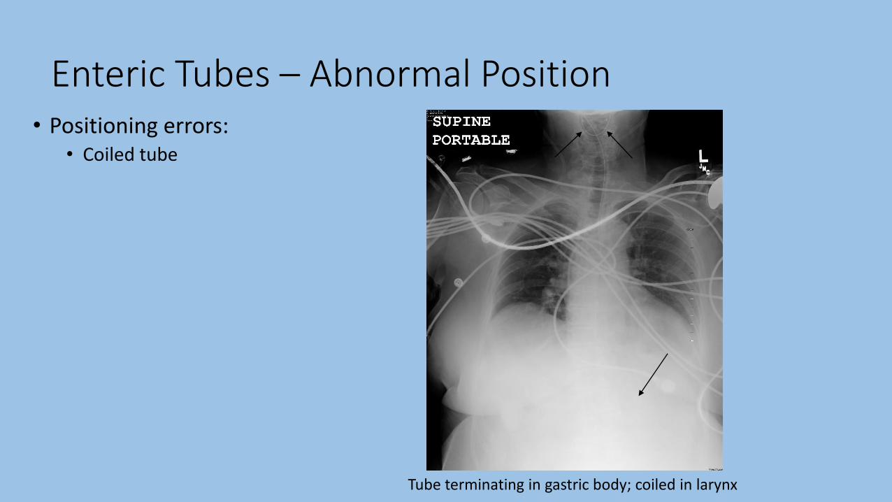
Enteric Tubes – Abnormal Position• Positioning errors:
• Coiled tube
Tube terminating in gastric body; coiled in larynx

Enteric Tubes – Abnormal Position• Positioning errors:
• Coiled tube
• Proximal/“marginal” placement• Aspiration risk
Tube terminating proximal to the GE junction

Enteric Tubes – Abnormal Position• Positioning errors:
• Coiled tube
• Proximal/“marginal” placement• Aspiration risk
Tube tip below GE junction; side hole within distal esophagus

Enteric Tubes – Abnormal Position• Positioning errors:
• Coiled tube
• Proximal/“marginal” placement• Aspiration risk
• Kinked tube
Tube kinked within proximal stomach

Enteric Tubes – Abnormal Position• Positioning errors:
• Coiled tube
• Proximal/“marginal” placement• Aspiration risk
• Kinked tube
• Pulmonary placement
Tube inserted through right bronchus into RLL
Tube inserted through left bronchus and deflected into right bronchus

Enteric Tubes – Abnormal Position• Positioning errors:
• Coiled tube
• Proximal/“marginal” placement• Aspiration risk
• Kinked tube
• Pulmonary placement
Tube inserted through right bronchus into RLL
Follow up chest X ray with right sided pneumothorax

Enteric Tubes – Abnormal Position• Positioning errors:
• Coiled tube
• Proximal/“marginal” placement• Aspiration risk
• Kinked tube
• Pulmonary placement
Tube inserted through right bronchus into RLL
Tube inserted through left bronchus and deflected into right bronchus

Enteric Tubes – Abnormal Position• Positioning errors:
• Coiled tube
• Proximal/“marginal” placement• Aspiration risk
• Kinked tube
• Pulmonary placement
• Intracranial placement*
*Extremely rare (case reports); usually post-trauma
Tube inserted through right bronchus into RLL
Tube inserted through left bronchus and deflected into right bronchus

Enteric Tubes – Complications• Complications:
• Pulmonary contusion/laceration
Tube coiled within esophagus; second loop entering right bronchus with right airspace opacity

Enteric Tubes – Complications• Complications:
• Pulmonary contusion/laceration
• Pneumothorax
Tube entering left bronchus with left basilar pneumothorax (deep sulcus-green arrow)

Enteric Tubes – Complications• Complications:
• Pulmonary contusion/laceration
• Pneumothorax
• Aspiration of feedings• Pneumonia
• Abscess
• Empyema
Tube entering right bronchus; RLL infiltrate after initiation of feeds

Enteric Tubes – Complications• Complications:
• Pulmonary contusion/laceration
• Pneumothorax
• Aspiration of feedings• Pneumonia
• Abscess
• Empyema
• Diaphragmatic perforation
• Esophageal perforation• Widened mediastinum, pneumomediastinum
• Gastric perforation• Pneumoperitoneum
Tube entering right bronchus; RLL infiltrate after initiation of feeds

• Radiographic evaluation indicated:• After enteric tube insertion (appropriateness score = 9)• Patient with enteric tube in place – clinical indications only (9)
• Radiographic evaluation NOT indicated:• Daily, routine follow-up (1)
• Imaging technique pearls:• Images should attempt to include pharynx → stomach
• Maximize visualization of tube course
• Higher penetration may allow better stripe/tip visualization
Legend: 1-3: usually not appropriate; 4-6: may be appropriate; 7-9: usually appropriate
Enteric Tubes– Indications for Studies

Cardiac Devices – Normal Position
• Pacemakers• Pulse generator and lead wire with electrodes
• Single lead: lead tip in RV apex (rarely RA)
• Two lead: leads tips in RA and RV
• Three lead (biventricular pacing/CRT): leads tips in RA, RV, and coronary sinus/cardiac vein• RV lead: stimulates septum
• Coronary sinus: stimulates lateral LV wall• Postero-superior to RV lead
• No leads in left heart (elevated pressures)
• All leads should have gentle curves

Cardiac Devices – Normal Position
Single lead pacemaker with tip in RV (arrow) Dual lead pacemaker with tip in RA (straight) and RV (curved)

Cardiac Devices – Normal Position
Triple lead pacemaker with leads in RA, RV, and coronary sinus

Cardiac Devices – Normal Position
• AICDs• Pulse generator and lead wires with electrodes
• Leads distinguished from pacemakers by generally thicker wires and thick, radiopaque coils distally• Coil necessary for higher energy discharge (i.e. defibrillation)
• Thicker wires → greater insulation• Less reliable indicator
• Generally have two coils (single or separate wires)• Primary coil - RV
• Additional coil – SVC or brachiocephalic vein

Cardiac Devices – Normal Position
AICD with coils in SVC and RV (single wire)

Cardiac Devices– Complications
• Complications• Pneumothorax
• Vascular injury
• Myocardial perforation (RV)• Pericardial effusion
• Tamponade
• Lead fracture
• Lead twisting (Twiddler’s syndrome)

Cardiac Devices– Complications
• Complications• Pneumothorax
• Vascular injury
• Myocardial perforation (RV)• Pericardial effusion
• Tamponade
• Lead fracture
• Lead twisting (Twiddler’s syndrome)
Right ventricular lead fracture

Summary
• Endotracheal tubes
Normal Position Common Positioning Errors Important Complications•At least 2 cm above carina
•At or below medial ends of
the clavicle
•Varies ±2 cm with neck
movement
•Too high
•Mainstem bronchus
intubation
•Esophageal intubation
•Spontaneous extubation
•Aspiration
•Atelectasis
•Pneumothorax
•Gastric/esophageal injury or
perforation

Summary
• Tracheostomy tubes
Normal Position Common Positioning Errors Important Complications•Similar tip positioning as ETT
•At least 2/3 of “smooth” portion in trachea
•Too high/incomplete insertion
•Tracheal injury
•Pneumothorax
•Hemorrhage

Summary
• Central venous catheters
Normal Position Common Positioning Errors Important Complications•Tip terminating over cavo-
atrial junction (inferior
border of right bronchus)
•Ipsilateral IJ
•Contralateral
brachiocephalic
•RA/RV
*Beware of anatomic variants
•Pneumothorax
•Vascular perforation

Summary
• PA catheters
Normal Position Common Positioning Errors Important Complications•Tip position in proximal
interlobar PA (roughly
within mediastinal shadow)
*Resting position depends
on function
•Too distal positioning
•Otherwise similar to that of
CVCs
•PA infarction
•PA rupture/dissection
•Otherwise similar to that of
CVCs

Summary
• Chest tubes
Normal Position Common Positioning Errors Important Complications
•Air removal – directed
anterior and superior
•Fluid removal – posterior
and inferior
•All side holes completely
visualized with the pleural
space
•Incomplete insertion
•Tube kinking
•Chest wall
•Lung fissures
•Ineffective drainage
•Pulmonary
laceration/contusion
•Pulmonary infarction
•Subcutaneous emphysema
•Reexpansion pulmonary
edema

Summary
• Enteric tubes
Normal Position Common Positioning Errors Important Complications•Roughly vertical/midline
course down esophagus
•Tip and all side holes distal
to GE junction
•Distal position depends on
function
•Coiled tube
•Proximal/”marginal”
•Kinked tube
•Pulmonary placement
•Aspiration
•Pulmonary
contusion/laceration
•Pneumothorax
•Esophageal/gastric
perforation
References• Amorosa, J. K., et al. (2013). "ACR appropriateness criteria routine chest radiographs in intensive
care unit patients." J Am Coll Radiol 10(3): 170-174.
• Siela, D. (2008). "Chest radiograph evaluation and interpretation." AACN Adv Crit Care 19(4): 444-473; quiz 474-445.
• Godoy, M. C., et al. (2012). "Chest radiography in the ICU: Part 1, Evaluation of airway, enteric, and pleural tubes." AJR Am J Roentgenol 198(3): 563-571.
• Godoy, M. C., et al. (2012). "Chest radiography in the ICU: Part 2, Evaluation of cardiovascular lines and other devices." AJR Am J Roentgenol 198(3): 572-581.
• Costelloe, C. M., et al. (2012). "Radiography of pacemakers and implantable cardioverter defibrillators." AJR Am J Roentgenol 199(6): 1252-1258.
• Khan, A. N., et al. (2009). "Reading chest radiographs in the critically ill (Part I): Normal chest radiographic appearance, instrumentation and complications from instrumentation." Ann Thorac Med 4(2): 75-87.
• Jain, S. N. (2011). "A pictorial essay: Radiology of lines and tubes in the intensive care unit." Indian J Radiol Imaging 21(3): 182-190.
• Schaefer-Prokop, Cornelia. Critical Care Radiology. Stuttgart: Thieme, 2011.