raghavapdf1
TRANSCRIPT

INDIAN INSTITUTE OF SPACE SCIENCE AND TECHNOLOGY
THIRUVANTAPURAM
A STUDY REPORT ON:-
Walschaerts steam valve gear
Done by :-
Kundrapu Raghava (SC10B038).
In the guidance of :-
Prof. Kurian Isaac sir.

ABSTRACT
Walschaerts valve gear was the most popular valve gear
which was extensively used in steam locomotives from the late 19th
century until the end of the steam era. The Walschaerts valve gear
enables the engineer to operate the steam engine in a continuous
range of settings from maximum economy to maximum power.
While initially unpopular, the Walschaerts gear was
probably applied to more of the twentieth century's steam
locomotives than any other, replacing the former favorite gear, the
Stephenson valve gear as locomotives got larger. This is one of the
basic model design of the valve gears which we are using now. In
this we made an analysis on kinematic view of the mechanism. We’ll
see how it was designed and its working principles and its
mechanism.

INTRODUCTION
WHAT IS VALVE GEAR ?
Valve gear on a steam locomotive is used to control the
admission of steam into the cylinders of a locomotive. Specifically, the
valve gear controls the timing or duration of time boiler pressure steam
is allowed into the cylinders.
The function of the locomotive valve gear is to regulate the
movement of the valves so that steam is admitted and exhausted from
the cylinders in relation to the position of the pistons. It also allows the
driver to alter the length of steam admission, known as cut-off, and to
reverse the locomotive.
Walschaerts valve gear
In 1844, Egide Walschaerts invented a valve gear that by
1848, appeared very much as it does today.
The primary reason for a more universal adoption of
Walschaerts’ gear was its general suitability for mounting outside the
frames, convenient for maintenance and permitting more strongly
braced frames. It's main advantage was that it was located completely
outside the wheels and therefore was much easier to maintain than
Stephenson valve gear.
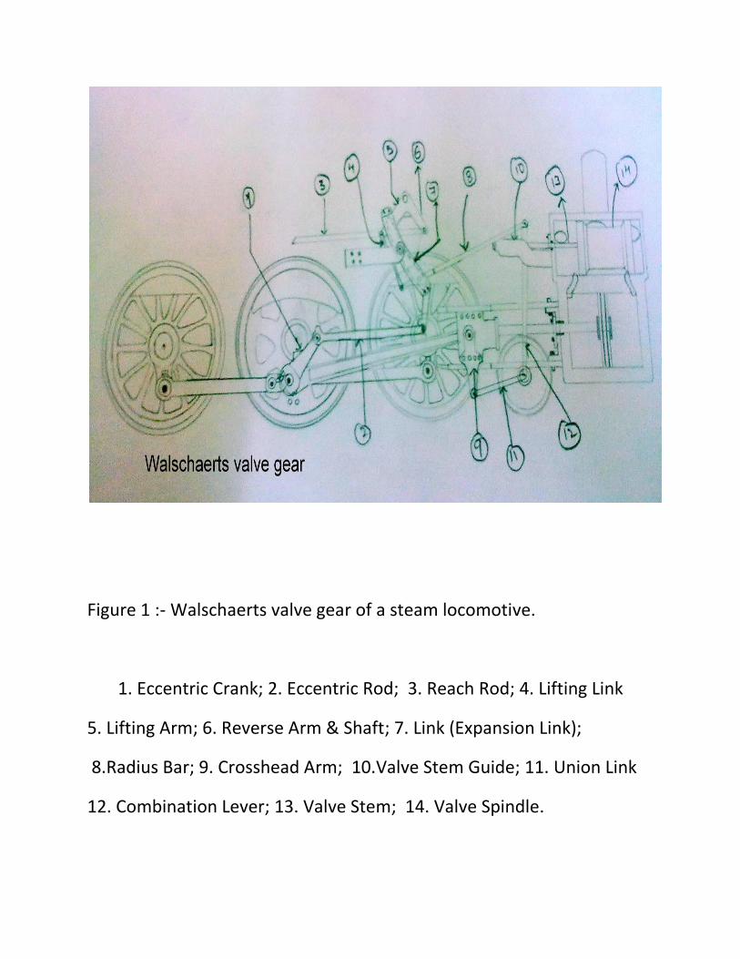
Figure 1 :- Walschaerts valve gear of a steam locomotive.
1. Eccentric Crank; 2. Eccentric Rod; 3. Reach Rod; 4. Lifting Link
5. Lifting Arm; 6. Reverse Arm & Shaft; 7. Link (Expansion Link);
8.Radius Bar; 9. Crosshead Arm; 10.Valve Stem Guide; 11. Union Link
12. Combination Lever; 13. Valve Stem; 14. Valve Spindle.
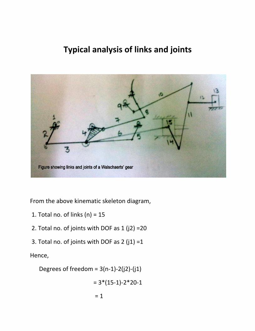
Typical analysis of links and joints
From the above kinematic skeleton diagram,
1. Total no. of links (n) = 15
2. Total no. of joints with DOF as 1 (j2) =20
3. Total no. of joints with DOF as 2 (j1) =1
Hence,
Degrees of freedom = 3(n-1)-2(j2)-(j1)
= 3*(15-1)-2*20-1
= 1

LET’S SEE HOW IT WORKS?
The motion is taken primarily from the locomotive driving wheel.
At the end of the crankpin, a return crank is fitted on the main
driver. The other end of this return crank is at a point just over 90
degrees ahead of the crankpin around the driving axle and closer
to the wheel's center.
The return crank drives the return crank arm, which in turn is
fastened to the lower end of the expansion link - this is a curved
piece (the concave side facing forward) of metal with a slot in it,
pivoted at the center so it can rotate.
The return crank arm is fastened to the bottom end of it, and as
the driving wheel rotates it therefore rocks the expansion link
back and forth around its center.
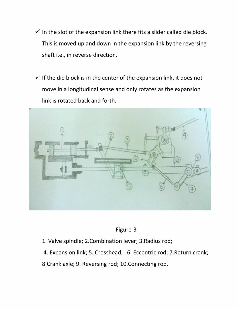
In the slot of the expansion link there fits a slider called die block.
This is moved up and down in the expansion link by the reversing
shaft i.e., in reverse direction.
If the die block is in the center of the expansion link, it does not
move in a longitudinal sense and only rotates as the expansion
link is rotated back and forth.
Figure-3
1. Valve spindle; 2.Combination lever; 3.Radius rod;
4. Expansion link; 5. Crosshead; 6. Eccentric rod; 7.Return crank;
8.Crank axle; 9. Reversing rod; 10.Connecting rod.

The further it is moved from that central position the more it
moves; if moved downward, it moves in the same sense as the
return crank arm, while if moved upward it moves in the reverse
sense.
The die block is attached to a rod named the radius rod, which
provides the large part of the valve motion to the piston or slide
valves. The expansion link and die block are used to control the
direction of movement of the locomotive, and the amount of
valve travel (as equivalent as the gearbox in an automobile).
In this Walschaerts’ gear, to make it a serviceable valve gear for a
locomotive it was discovered that by adding a small proportion of
the piston's movement to the valve motion produced better valve
events. Thus, instead of the radius rod being connected directly to
the valve spindle, it is connected to a more-or-less vertical rod
called the combination lever.
The radius rod is connected to the top of this lever; the valve
spindle is connected to a position only slightly down the lever,
since the radius rod's motion is the large proportion of the desired
valve motion.
The other end of the combination lever is connected to the
crosshead at the end of the piston rod by a horizontal rod named
the union link - the purpose of this was simply that the crosshead
was not normally close to the location of the combination lever
but rather substantially further back.
The combination lever, thus, combines the movements of the
radius rod and the crosshead in approximately a 10:1 proportion,
adding only a small amount of the crosshead's motion to the valve
motion.
The movement of the expansion link is obtained from an
eccentric rod attached via the crank axle. Adjustment to the
length of valve travel is made by raising or lowering the position
of the radius rod within the expansion link. This is achieved by
operation of the reversing rod from in the cab. The length of
travel of the radius rod, and therefore of the valve spindle,
depends on the rod's position within the expansion link.
Maximum valve travel giving maximum steam admission is
obtained when the radius rod is positioned furthest from the
centre of the expansion link. Moving the radius rod from one half
of the expansion link to the other, reverses the movement of the
locomotive by admitting steam into what otherwise would have
been the exhausting side of the piston's cycle.
Working principle to obtain maximum power & economical :-
Any valve gear has to satisfy the following two conditions:
1. At the instant when the space on one side of the piston starts to
expand, i.e. at the very start of a stroke, the valve opens to admit
steam from the boiler into that space. The pressure of this steam
provides the driving force.
2. At the instant when the space on one side of the piston starts to
contract, the valve starts to release steam from that space to the
atmosphere, so as not to impede the movement of the piston.
Steam is admitted to the expanding space for only part of the
stroke; at an instant of time, the intake is cut off. Since the
exhaust is also shut, during the rest of the stroke the steam that
has entered the cylinder expands in isolation, thereby its pressure
decreases.
For maximum economy, the cutoff point should be carefully set so
that, when the exhaust valve opens, the steam is down to exactly
atmospheric pressure. Thus, all the mechanical energy available
from the steam (in the absence of a condenser) is used.
The Walschaerts valve gear enables to change the cutoff point
without changing the points at which intake starts and at which
exhaust starts.
Economy also requires that the throttle is wide open, so that no
energy is wasted pushing steam through a constriction, and that
the boiler pressure is at the maximum safe level to maximize
thermal efficiency.

For economy, a steam engine is used of a size such that the most
economical settings yield the right amount of power most of the
time, such as when a train is running at steady speed on level
track.
When greater power is necessary, e.g. when gaining speed when
pulling out of a station and when ascending a gradient, the
Walschaerts valve gear enables to set the cutoff point near the
end of the stroke, so that the full pressure of the boiler is exerted
on the piston for almost the entire stroke. With such a setting,
when the exhaust opens, the steam in the cylinder is near full
boiler pressure.
The pressure in the steam at that moment serves no useful
purpose.It is wasted driving a sudden pulse of pressure into the
atmosphere, but this waste is compensated by maximized
economy at other times.

1. The motion must be adjusted with the crank on the dead centers by
lengthening or shortening the eccentric rod until the link takes such
a position as to impart no motion to the valve when the link block is
moved from its extreme forward to its extreme backward position.
Before these changes in the eccentric rod are resorted to, the length
of the valve stem should be examined, as it may be of advantage to
plane off or line under the foot of the link support which might
correct the length of both rods, or at least only one of these would
need to be changed.
2. The difference between the two positions of the valve on the
forward and back centers is the lead and lap doubled and it cannot
be changed except by changing the leverage relations of
the combination lever.
3. A given lead determines the lap or a given lap determines the lead,
and it must be divided for both ends as desired by lengthening or
shortening the valve spindle.
4. Within certain limits, this adjustment may be made by shortening or
lengthening the radius bar but it is desirable to keep the length of
this bar equal to the radius of the link in order to meet the
requirements of the first condition.
5. The lead may be increased by reducing the lap, and the cutoff point
will then be slightly advanced. Increasing the lap introduces the
opposite effect on the cutoff. With good judgment, these qualities
may be varied to offset other irregularities inherent in transforming
rotary into lineal motion.
6. Slight variations may be made in the cutoff points as covered by the
preceding paragraph but an independent adjustment cannot be
made except by shifting the location of the suspension point which
is preferably determined by a model.
How this gear is advantageous over others ?
Another class of competitors were Stephenson valve
gear, baker’s valve gear, the poppet valve gears, including the Caprotti
valve gear, the Franklin Oscillating Cam valve gear, the Franklin Rotary
Cam valve gear and others. Theoretically much more efficient, all of
these suffered from the dual problems of not handling wear very well
and the worse one of complexity, and were not widely adopted.
The Walschearts gear could be used with three or four
cylinder locomotives, too. One set of valve gear could be installed per
cylinder, of course. This either required the center gear(s) to be
mounted inside, or for two sets of valve gear to be mounted on the
same side of the locomotive (normally driven from 2 different driving
wheels).
Some four cylinder locomotives had the cylinders set
up so that they operated in linked pairs, and thus needed only two sets
of valve gear. It was also possible to use levers to derive the valve
motion for a third cylinder from that of the other two, as was done
after in the Gresley - Holcroft Conjugated valve gear.

References
www.mekanizmalar.com/walschaerts_valve_gear.html
www.steamlocomotive.com/appliances/valvegear.php
en.wikipedia.org/wiki/Walschaerts_valve_gear
http://www.railway-technical.com/st-glos.shtml
Walschaerts valve gear - YouTube www.roundhouse-eng.com/pdf/wvg.pdf
------------XXXXXXXX------------
Thank you