rail accident report - gov.uk by her majesty’s railway inspectorate (hmri) ... l review of...
TRANSCRIPT

Report 12/2009May 2009
Rail Accident Report
Detachment of containers from freight wagons near Cheddington and Hardendale 1 March 2008

This investigation was carried out in accordance with:
l the Railway Safety Directive 2004/49/EC;l the Railways and Transport Safety Act 2003; and l the Railways (Accident Investigation and Reporting) Regulations 2005.
© Crown copyright 2009 You may re-use this document/publication (not including departmental or agency logos) free of charge in any format or medium. You must re-use it accurately and not in a misleading context. The material must be acknowledged as Crown copyright and you must give the title of the source publication. Where we have identified any third party copyright material you will need to obtain permission from the copyright holders concerned. This document/publication is also available at www.raib.gov.uk.
Any enquiries about this publication should be sent to:
RAIB Email: [email protected] Wharf Telephone: 01332 253300Stores Road Fax: 01332 253301 Derby UK Website: www.raib.gov.ukDE21 4BA
This report is published by the Rail Accident Investigation Branch, Department for Transport.

Report 12/2009 3 May 2009
Detachment of containers from freight wagons near Cheddington and Hardendale, 1 March 2008
Contents
Preface 5Key Definitions 5
Summary of the report 6Key facts about the incidents 6Immediate cause, causal and contributory factors, underlying causes 6Severity of consequences 7Summary of Recommendations 7
The Incidents 9Summary of the incidents 9The parties involved 10Locations 11External circumstances 12The trains involved 12The infrastructure 15Sequence of events - Cheddington 15Sequence of events - Hardendale 16Consequences of the incidents 17
The Investigation 18Investigation process 18Sources of evidence 18
Key Information 20The affected wagons in the train 20The track condition at the incident sites 20The operation of the train 21Wind conditions at the incident sites 22Aerodynamic effects previously noted at the incident sites 22The management of the forecast wind conditions 23Container overturning 25Introduction of UIC spigots to the UK 26Operation of UIC spigots 27

Report 12/2009 4 May 2009
The spigots on the incident wagons 31Testing of spigots 32CAD Analysis 34Freight containers 34Design of the FEA-B wagons 35Engineering Acceptance of the FEA-B wagons 36Risk Assessment of the FEA-B wagon 37Approval by Her Majesty’s Railway Inspectorate (HMRI) 38Maintenance of the FEA-B wagons 38Previous occurrences of a similar character 39
Analysis 42Identification of the immediate cause 42Identification of causal and contributory factors 42Identification of underlying causes 46Severity of consequences 46Observations 47
Conclusions 48Immediate cause 48Causal factors 48Contributory factors 49Underlying causes 49Additional observations 49
Actions reported as already taken or in progress relevant to this report 50NIR 2350 50RAIB Urgent Safety Advice 50Industry actions 50
Recommendations 52Recommendations to address causal and contributory factors 52Recommendations to address other matters observed during the investigation 53
Appendices 54Appendix A - Glossary of abbreviations and acronyms 54Appendix B - Glossary of terms 55Appendix C - Key standards current at the time 58Appendix D - Wagon formations for 4E90 and 4S83 59Appendix E - Overturning of containers 61

Report 12/2009 5 May 2009
Preface
1 The sole purpose of a Rail Accident Investigation Branch (RAIB) investigation is to prevent future accidents and incidents and improve railway safety.
2 The RAIB does not establish blame, liability or carry out prosecutions.3 This report covers two separate, but very similar incidents; one near Cheddington
and the other at Hardendale.
Key Definitions4 References to ‘Up’ and ‘Down’ lines in this report refer to their normal direction of
travel towards London or away from London respectively.5 Geographical locations on the West Coast Main Line in the area of Cheddington
are measured in miles and chains from a zero datum at London Euston, and in the area of Hardendale, from another zero datum at Lancaster Station.
6 References to ‘right’ or ‘left’ side of the train or track in this report are made relative to the northbound direction of travel of the trains involved.
7 Throughout this report, container sizes are defined by their nominal length in feet (e.g 20 ft, 40 ft), in accordance with standard industry terminology and therefore no metric equivalent is quoted.
8 Appendices at the rear of this report contain the following:l acronyms and abbreviations are explained in Appendix A;l technical terms (shown in italics the first time they appear in the report) are
explained in Appendix B;l key standards at the time of the incident are listed in Appendix C;l the wagon formations involved in the two incidents are listed in Appendix D; andl calculations pertaining to the overturning of unrestrained containers are
summarised in Appendix E.
Pref
ace

Report 12/2009 6 May 2009
Summary of the report
Key facts about the incidents9 On 1 March 2008, at approximately 02:24 hrs, two empty containers were blown off
freight train 4E90, the 00:07 hrs Isle of Grain to Doncaster, while it was travelling on the Down Fast line of the West Coast Main Line (WCML) at Cheddington, near Leighton Buzzard. The freight train consisted of a Class 56 locomotive hauling 20 FEA-B type flat wagons and was running at approximately 75 mph (121 km/h). The detached containers blocked the running lines and caused damage to overhead line equipment (OLE) and to the track.
10 On the same morning, at approximately 03:15 hrs, five empty containers were blown from freight train 4S83, the 18:28 hrs Tilbury to Coatbridge, on the down line of the WCML adjacent to Hardendale Quarry, between Tebay and Penrith. The train consisted of two Class 86 locomotives hauling 20 container flat wagons of mixed types, including ten FEA-B wagons, and was running at approximately 75 mph (121 km/h). The detached containers consisted of three 20 ft, one 40 ft and one 20 foot tank container and were blown from the rearmost four FEA-B wagons of the train. They blocked running lines and caused damage to the OLE and track.
Immediate cause, causal and contributory factors, underlying causes11 The immediate cause of both incidents was the overturning and detachment from
their wagons, of empty, unsecured freight containers, due to the aerodynamic forces resulting from a combination of high cross winds and train speeds.
12 Causal factors were:l the high cross wind speeds at both sites;l both trains were travelling at close to their permitted maximum speed of 75 mph
(121 km/h);l the containers which detached were empty;l the lack of overturning retention provided by the FEA-B wagon’s fold-down
spigots because they had not been designed in accordance with UIC1 571-4 appendix C;
l the wagon manufacturer had not appreciated the function and operating principles of UIC spigots;
l the lack of explicit warning in UIC 571-4 about the use of inboard hinges for fold-down spigots;
l the lack of checks on the spigots during the vehicle certification process; l the lack of a mandatory design Railway Group Standard (RGS) relating to load
retention devices;l the lack of use of guidance documentation during the certification process; and l the freight operators did not identify that inboard hinges on fold-down spigots
could not prevent container overturning without additional locking.
1 Union International Chemins de Fer
Summ
ary of the report

Report 12/2009 7 May 2009
A possible causal factor was: l dimensional checks specified in UIC 571-4 had not been included in the wagon
maintenance plans and therefore no checks on the spigot spacings were undertaken during operational service.
13 The contributory factors were:l the increase of the local wind speeds over the embankments at both sites;l the wagon manufacturer’s belief that unsecured containers on the FEA-B
wagons were safe from overturning, based on an incorrect interpretation of Railway Group Standard GM/RT2142;
l the wagon manufacturer’s previous experience of satisfactory container security on Polish and Russian wagons;
l the freight operating companies assumed that the wagon spigots were compliant with UIC 571-4, as declared by the vehicle manufacturer; and
l the partial exposure of the bottom surfaces of the containers to air flowing up embankment slopes, which may have been contributory.
14 The underlying factors were:l a loss of UK rail industry awareness and understanding about the design,
operation and maintenance requirements of UIC spigots; andl the lack of consideration in the vehicle certification process of safety critical
items not designed to Railway Group Standards.
Severity of consequences 15 There were no injuries in either incident. The risk of collision between the
detached containers and other trains was mitigated by two factors:l there were very few passenger trains running in either area at the time,
although there were other freight trains; andl signs of problems at both sites were received by remote controlling centres
and actions were taken by Network Rail to prevent trains entering the affected sections of track.
Sum
mar
y of
the
repo
rt

Report 12/2009 8 May 2009
Summary of Recommendations 16 Recommendations can be found at paragraph 209. They relate to the following
areas:For Freight Operators:
l reviewing the threshold wind speeds in NIR 2350 to take account of topography, minimum container weights, container sizes, and wagon design;
l checking wagons fitted with spigots to ensure compliance with UIC 571-4 and identification of non-compliant wagons;
l developing and implementing long term solutions to retain containers on wagons identified as non-compliant;
l review of maintenance manuals with respect to spigots and where necessary, the introduction of regular checks in accordance with UIC 571-4; and
l review of the compliance status of the FEA-B wagons with respect to overturning in windy conditions against Railway Group Standard GM/RT2142 and where necessary, modification of their operations.
For the Office of Rail Regulationl making a proposal to the European Rail Agency to clarify the section on spigots
in the freight wagon TSI so that in future, designers are aware of the operating principles of spigots and the dangers of fold-down spigots.
For the Rail Safety and Standards Boardl introduction of a requirement for load retention devices in a design standard
related to freight wagons, so that such devices are checked against their original specification as part of the vehicle certification process;
l review of the implementation of the vehicle certification process including whether other safety related items, designed to non-Railway Group Standards, are adequately addressed in the process; and
l review of whether the minimum container weight specified in Railway Group Standard GO/RM3056/J (of 1.6 tonnes), adequately accounts for container size in windy conditions.
For Network Raill review of the compatibility of trigger speeds and durations for wind actions with
the overturning requirements for trains, taking into account local topographical effects.
Summ
ary of the report

Report 12/2009 9 May 2009
Figure 1: Incident site near Cheddington
The Incidents
Summary of the incidentsCheddington17 On 1 March 2008, at approximately 02:24 hrs, two empty 20 ft containers were
blown off freight train 4E90, which formed the 00:07 hrs Isle of Grain to Doncaster. The train, which consisted of a Class 56 locomotive hauling 20 FEA-B flat wagons, was travelling north on the Down Fast line of the WCML just north of Cheddington (Figure 1) at approximately 75 mph (121 km/h) in windy conditions.
18 The detached 20 ft containers blocked the Up Fast and slow lines at two locations, approximately 1.4 miles apart (Figure 1), and caused damage to OLE and to the track. The line was closed for repairs until the evening of 1 March 2008.
Detached container 1
Detached container 2
North & direction of travel
Down FastUp Fast
Down SlowUp Slow
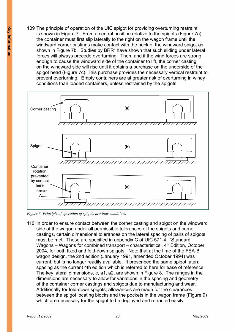
Tring31m 50ch
Cheddington36m 8ch Ledburn Jn
37m 35ch
Leighton Buzzard40m 14ch
403938373635343332
North
Mileposts
Detachedcontainer 1
Detachedcontainer 2
The
Inci
dent
s
Report 12/2009 10 May 2009
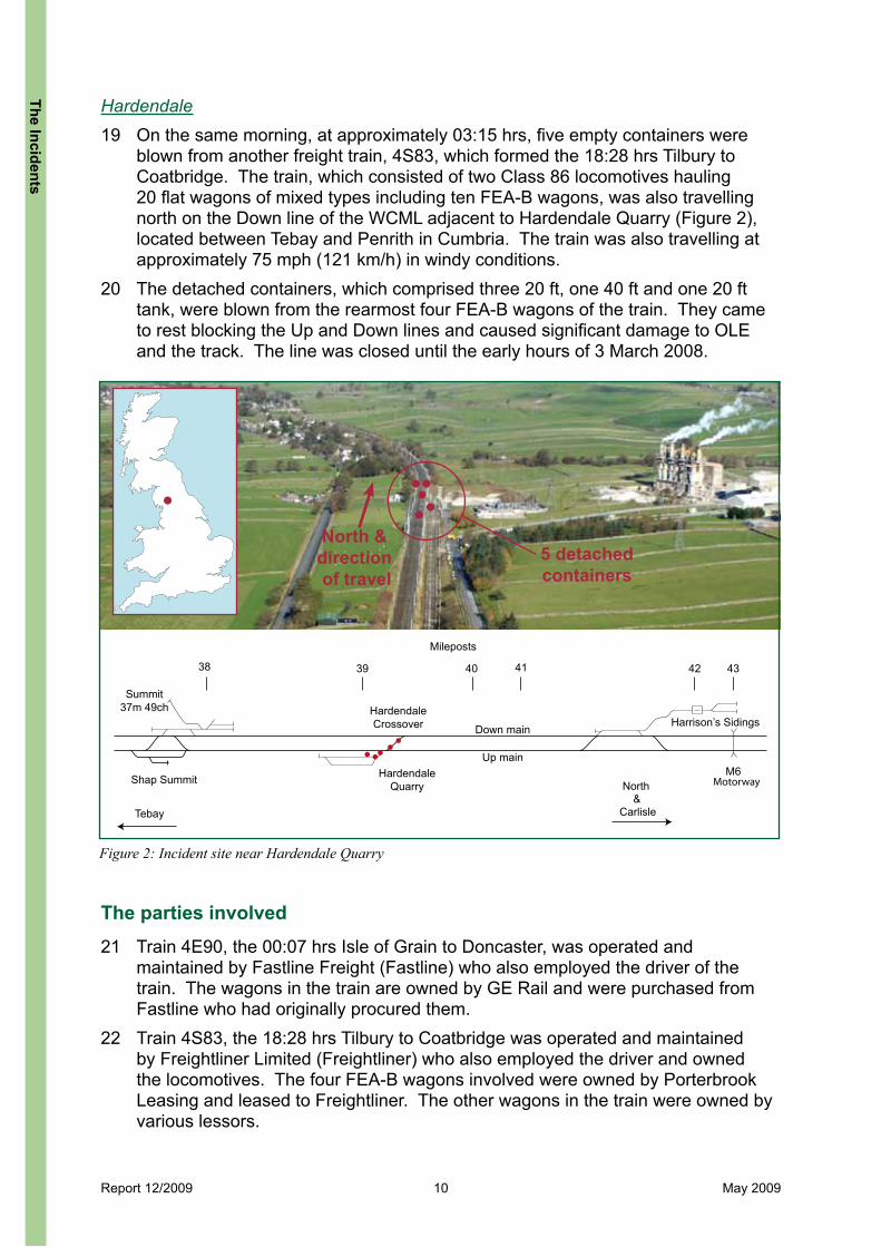
Hardendale19 On the same morning, at approximately 03:15 hrs, five empty containers were
blown from another freight train, 4S83, which formed the 18:28 hrs Tilbury to Coatbridge. The train, which consisted of two Class 86 locomotives hauling 20 flat wagons of mixed types including ten FEA-B wagons, was also travelling north on the Down line of the WCML adjacent to Hardendale Quarry (Figure 2), located between Tebay and Penrith in Cumbria. The train was also travelling at approximately 75 mph (121 km/h) in windy conditions.
20 The detached containers, which comprised three 20 ft, one 40 ft and one 20 ft tank, were blown from the rearmost four FEA-B wagons of the train. They came to rest blocking the Up and Down lines and caused significant damage to OLE and the track. The line was closed until the early hours of 3 March 2008.
Figure 2: Incident site near Hardendale Quarry
North & direction of travel
5 detachedcontainers
Summit37m 49ch
Shap Summit
HardendaleCrossover Down main
Up main
Harrison’s Sidings
Hardendale Quarry
434241403938
Tebay
M6
Carlisle
North&
Motorway
Mileposts
The parties involved 21 Train 4E90, the 00:07 hrs Isle of Grain to Doncaster, was operated and
maintained by Fastline Freight (Fastline) who also employed the driver of the train. The wagons in the train are owned by GE Rail and were purchased from Fastline who had originally procured them.
22 Train 4S83, the 18:28 hrs Tilbury to Coatbridge was operated and maintained by Freightliner Limited (Freightliner) who also employed the driver and owned the locomotives. The four FEA-B wagons involved were owned by Porterbrook Leasing and leased to Freightliner. The other wagons in the train were owned by various lessors.
The Incidents

Report 12/2009 11 May 2009
LOCOL L E EEL
Wind
Wagons 6 - 20
Wagon 4Wagon 5 Wagon 3 Wagon 2 Wagon 1
Figure 3: Detached containers near Cheddington and their original location on train 4E90
23 The containers, which detached from trains 4E90 and 4S83, were owned by various shipping companies; Evergreen, Dong Fang, Hamburg SÜD and Eurotainer.
24 The track and infrastructure of the WCML is owned, operated and maintained by Network Rail, who employ the signallers controlling the route.
25 The FEA-B wagons, from which the containers detached, were designed and built for Freightliner and Fastline by Greenbrier Europe (Greenbrier) at their Wagony Swidnica factory in Poland.
26 Certification of the FEA-B wagons, to check that they complied with Railway Group Standards (RGS) was undertaken by Network Rail Vehicle Conformance Group (NRVCG) for Greenbrier.
27 Freightliner, Fastline, Network Rail and Greenbrier gave free access to their staff, data and records in connection with this investigation.
LocationsCheddington28 The site of the first incident was on a section of straight track on the WCML
between the stations at Cheddington (36 miles 8 chains) and Leighton Buzzard (40 miles 14 chains) (Figure 1). The railway here consists of four running lines aligned in a generally north-south direction. From west to east these lines are the Down Fast, Up Fast, Down Slow and Up Slow. The first detached container was found on the Up Fast line at 36 miles 74 chains and the second container was found on the Up Slow line approximately 1.4 miles (2.2 km) further north at 38 miles 27 chains. Figure 3 shows a general view of the track, the detached containers and their original positions on train 4E90.
The
Inci
dent
s
Report 12/2009 12 May 2009
29 The line speed limit of the fast lines is 110 mph (177 km/h) for normal traffic and 125 mph (201 km/h) for stock authorised for enhanced permissible speed (EPS) running. The line speed limit of the slow lines is 100 mph (161 km/h). However, Class 4 freight trains such as train 4E90, are limited to 75 mph (121 km/h) in accordance with module TW1 of Railway Group Standard GE/RT/8000, the Rule Book.
30 The four lines run on top of an embankment which varies in height between 1 and 4 metres from 36 miles 60 chains to 38 miles 25 chains. The slope angle is approximately 20 degrees from the horizontal. The surrounding land to the west, the direction from which the wind was blowing, is open and flat.
Hardendale31 The site of the second incident was also on a section of straight track on the
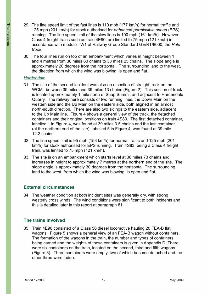
WCML between 39 miles and 39 miles 13 chains (Figure 2). This section of track is located approximately 1 mile north of Shap Summit and adjacent to Hardendale Quarry. The railway here consists of two running lines, the Down Main on the western side and the Up Main on the eastern side, both aligned in an almost north-south direction. There are also two sidings to the eastern side, adjacent to the Up Main line. Figure 4 shows a general view of the track, the detached containers and their original positions on train 4S83. The first detached container, labelled 1 in Figure 4, was found at 39 miles 3.5 chains and the last container (at the northern end of the site), labelled 5 in Figure 4, was found at 39 mile 12.2 chains.
32 The line speed limit is 95 mph (153 km/h) for normal traffic and 125 mph (201 km/h) for stock authorised for EPS running. Train 4S83, being a Class 4 freight train, was limited to 75 mph (121 km/h).
33 The site is on an embankment which starts level at 38 miles 73 chains and increases in height to approximately 7 metres at the northern end of the site. The slope angle is approximately 30 degrees from the horizontal. The surrounding land to the west, from which the wind was blowing, is open and flat.
External circumstances 34 The weather condition at both incident sites was generally dry, with strong
westerly cross winds. The wind conditions were significant to both incidents and this is detailed later in this report at paragraph 81.
The trains involved35 Train 4E90 consisted of a Class 56 diesel locomotive hauling 20 FEA-B flat
wagons. Figure 5 shows a general view of an FEA-B wagon without containers. The formation of the wagons in the train, the number and types of containers being carried and the weights of those containers is given in Appendix D. There were six containers on the train, located on the second, third and fifth wagons (Figure 3). Three containers were empty, two of which became detached and the other three were laden.
The Incidents
Report 12/2009 13 May 2009
Figure 4: Detached containers at Hardendale and their original location on train 4S83 (white arrows denote direction of travel)
Wind
Wind
54
2 x LOCOL
Wagon 19Wagon 20 Wagon 18 Wagon 17 Wagon 16
E E E EL E E E E
2 x LOCOL
Wagon 19Wagon 20 Wagon 18 Wagon 17 Wagon 16
E E E EL E E E E
3 2 1
Wagons 1-15
Wagons 1-15
36 Train 4S83 consisted of two class 86 electric locomotives (86638 and 86621) hauling a mixture of flat wagons, comprising eight FSA wagons, two KFA wagons and ten FEA-B wagons. The formation of the wagons, the arrangement and type of containers are given in Appendix D. There were 26 containers on 4S83; 16 containers (13 empty and 3 laden) were being carried on the leading eight wagons, comprising a mixture of four FSA, two KFA and two FEA-B wagons, and ten containers (eight empty and two laden) were on the last four FEA-B wagons. To retain the containers, the FSA and KFA wagons are fitted with twistlocks which are explained at paragraph 99. The FEA-B wagons are fitted with fold-down UIC spigots explained at paragraph 106.
The
Inci
dent
s

Report 12/2009 14 May 2009
Figure 5: Fastline FEA-B wagon (ends labelled A & B)
Figure 6: Fold-down spigot with inboard hinge, as fitted to FEA-B wagons, deployed (left), stowed (right)
A
B
spigot head hinge
Spigot block (locates in pocket)
underframe pocket
37 The FEA-B wagons run in semi-permanently coupled pairs and have buffers at the outer ends of each pair. They carry various combinations of 20, 30, 40 and 45 ft standard containers. Each wagon has a gross weight of 82 tonnes and a tare weight of 20.5 tonnes, giving a nominal payload of 61.5 tonnes. The length of each wagon platform is 19.3 metres and the combined length of a coupled pair of platforms over buffers is 40.48 metres. Each Freightliner FEA-B wagon has ten pairs of UIC spigots designed to fold down into recesses in the wagon frame (Figure 6) when not in use. The Fastline FEA-Bs have eight pairs of fold-down spigots and one pair of non-folding spigots which can be moved longitudinally to take up two different positions.
The Incidents

Report 12/2009 15 May 2009
The infrastructure38 The railway at both incident sites comprises continuously welded rail on concrete
sleepers, four aspect colour light signalling and 25 kV overhead line electification.39 The section between Cheddington and Leighton Buzzard is controlled by Rugby
Signalling Control Centre and has axle counters on all four running lines to provide train detection. The OLE is controlled from Rugby Electrical Control Room (ECR).
40 The section between Shap Summit and Hardendale is controlled by Carlisle signal box and has continuous track circuits to provide train detection. The OLE is controlled from Cathcart ECR.
Sequence of events - Cheddington41 Train 4E90 departed the Isle of Grain 23 minutes early at 23:44 hrs on
29 February 2008 and continued to run early as it passed Tring without incident. At approximately 02:21 hrs on 1 March 2008, while travelling on the Down Fast line, it passed train 4L80 which was running on the Up Fast line approximately two miles south of the incident site. Train 4L80 was conveying 20 flat wagons, comprising a mixture FSA, KFA, FTA and ten loaded FEA-B wagons.
42 Between approximately 02:23 and 02:24 hrs, train 4E90 passed the locations where the first and second containers were subsequently found. The driver was not aware of any problem and continued on towards Rugby.
43 Between 02:23 hrs and 02:30 hrs, the signaller at Rugby was notified by the Rugby ECR that five OLE sections, between Tring and Ledburn Junction, had tripped and that one section could not be reset. This was the first indication of a problem after the passage of train 4E90 through the area. The Rugby ECR then requested the signaller at Rugby to block the Up Fast line from Leighton Buzzard. The signaller replaced the signal (signal WT3189), located approximately 230 metres on the approach to the northern-most container in the up direction, to danger, to prevent other trains entering the affected section.
44 At approximately 02:44 hrs, passenger train 2K03, the 02:00 hrs Euston to Milton Keynes, comprising a Class 321 unit and running on the Down Fast line, was stopped at a signal just south of Tring station and the driver was requested by the signaller to check the OLE from the Down Fast line. Although 2K03 was supposed to be examining the line, the driver proceeded at too high a speed to have been able to stop had there been an obstruction on the line, reaching a maximum of 63 mph (101 km/h). This is discussed later at paragraph 191. At 02:56 hrs the driver of 2K03 spotted something on the Up Fast line and applied the emergency brakes, stopping approximately 225 metres beyond the object.
45 At 03:01hrs the driver of 2K03 initially reported the object to the signaller as an advertising hording but later at 03:10 hrs confirmed that a container was on the Up Fast line, standing on its end and touching the OLE (at 36 miles 74 chains). The driver was requested to continue inspection of the line and at 03:28 hrs reported the second container on the Down Slow line and fouling the Up Slow line at 38 miles 27 chains.
The
Inci
dent
s

Report 12/2009 16 May 2009
46 At 03:50 hrs, train 4E90 was stopped by the signaller at Rugby station and examination by the driver revealed two containers were missing from the second wagon.
47 At 04:46 hrs, Rugby ECR took out an emergency isolation of the OLE sections between Tring and Leighton Buzzard on the Up Fast line. At 05:49 hrs, train 4E90 was stabled at reception sidings in Northampton.
48 Subsequently, a possession was taken to enable investigation and recovery operations.
Sequence of events - Hardendale49 Train 4S83 departed Tilbury on time at 18:28 hrs on 29 February 2008 but lost
time as it proceeded. It departed Basford Hall 37 minutes late and passed Tebay at 03:05 hrs on 1 March 2008, running 31 minutes late. It ran through the incident site next to Hardendale Quarry and through Penrith at 03:22 hrs, running 20 minutes late.
50 At 03:15 hrs the signaller at Carlisle signal box was alerted by the Shap Summit audible alarm which indicates loss of the remote interlocking at Shap. He also noticed four track circuits on the Up Main line and three track circuits on the Down Main line showing occupied, and 641 points (Up Main to Hardendale sidings) indicating faults. Two signals in the area (signals CE143 and CE144) were also indicating faults and were automatically set to danger. The signaller returned another signal (signal CE151), located approximately three miles north of Hardendale Quarry, to danger to prevent a southbound sleeper train 1M16 (the 20:40 hrs Inverness to Euston) approaching the incident site.
51 At 03:17 hrs, the driver of 1M16 stopped before reaching signal CE151 and reported to the signaller, via the National Radio Network (NRN), that he had seen a flash from the OLE and heard a loud bang and that he had lost power. The electrical control room at Cathcart informed the signaller that the OLE power supply was dead between Shap Summit at 37 miles 49 chains and Harrison sidings at 42 miles.
52 A diesel hauled train, 6C37, the 23:07 hrs Chirk to Carlisle Yard, which was in a goods loop in the Tebay area at the time, was requested to examine the line from Shap Summit to Hardendale Quarry and report on the condition of the OLE. At 04:00 hrs the driver of 6C37 report a detached container on the Up Main and a damaged OLE stanchion. It was later confirmed at 04:10 hrs, by a Network Rail Mobile Operations Manager on site, that there were five detached containers on the track.
53 Meanwhile train 4S83 continued on its journey through Carlisle and on to Lockerbie, where it was stopped at 04:16 hrs. Subsequent examination by the driver revealed that there were five containers missing.
54 At 05:04 hrs Cathcart ECR took an emergency isolation of the Up and Down Main lines between Tebay and Penrith and at 05:40 hrs a rescue locomotive departed Carlisle to recover 1M16 back to Carlisle.
55 At 08:28 hrs a possession was taken on all lines between Harrisons sidings and Shap to enable investigation and recovery work.
The Incidents

Report 12/2009 17 May 2009
Consequences of the incidents Cheddington56 At Cheddington, the two detached containers came to rest blocking running lines;
the first container to detach came to rest on its end (Figure 3) fouling the Up Fast line and in close proximity to the OLE on that line. There was evidence of arcing between the OLE and the container. The second container to detach which came to rest on its side, was on the Up Slow line and fouling the Down Slow line.
57 Among the containers that remained on train 4E90, the trailing 20 ft container on the second wagon had a gash in the upper half of its right-hand side over most of its length. The trailing 40 ft container on the third wagon also had a smaller gash to it right-hand side. There was no significant damage to any of the wagons on train 4E90.
58 Damage to the track at the two locations, one near Cheddington and the other near Leighton Buzzard was relatively light, comprising a broken sleeper, two alignment faults due to the incident, minor rail head damage, and light damage to two OLE stanchions.
Hardendale59 At Hardendale, the five detached containers came to rest over a distance of
approximately 175 metres (Figure 4). The southernmost 20 ft container was fouling the Up line. The 40 ft container and 20 ft tank came to rest in the sidings and did not block the Up line. The two 20 ft containers at the northern end of the site fouled both the Up and Down main lines. Other containers on train 4S83 were also damaged but there was no significant damage to any of the wagons on the train.
60 The damage to the infrastructure at Hardendale was significant. Three OLE stanchions were severely damaged and required replacement, and the overhead wires required repair. There was damage to the rails, sleepers and points on the Up Fast line and Hardendale sidings. Signal CE141 and a location cabinet were completely demolished and various signalling cables were severed.
The
Inci
dent
s

Report 12/2009 18 May 2009
The Investigation
Investigation process61 The RAIB attended both sites to examine the detached containers and the track.
They examined the trains at their stabling locations away from site. Due to the similarity of the two incidents, the RAIB decided to undertake a joint investigation of both incidents, which covered the following principal areas:l the functionality of UIC spigots in general and those fitted to FEA-B wagons in
particular, by measurement, testing and computer aided design (CAD); l assessment of the wind conditions at the time of the incidents, including the
effect of the embankments and the probability of overturning due to wind forces; l the history of previous similar incidents in the UK and on the European
continent;l the historical development of UIC spigots and their introduction to the UK;l the design of the FEA-B wagon and its spigots;l the certification of the wagons for UK operation;l the maintenance regime for FEA-B wagons;l the management of the high wind conditions by Network Rail; andl the effectiveness of UIC spigots in retaining containers in the event of wagon
derailment; relevant to the derailment of container carrying wagons such as occurred at Duddeston Junction on 10 August 2007 (RAIB investigation report 16/2008, July 2008).
Sources of evidence62 Relevant information about the infrastructure, the sequence of events and general
and specific operational aspects on the night of the incidents was obtained from Network Rail. Network Rail also provided information on previous similar incidents on the European continent via the Union Internationale de Chemins de Fer (UIC) and information regarding their procedures and systems for monitoring wind conditions and managing train operations.
63 Information about the FEA-B wagons, their procurement and maintenance was obtained from Freightliner and Fastline who also assisted with the measurement and testing of the spigots on the wagons involved.
64 Information about the design of the FEA-B wagons and its spigots was obtained from Greenbrier.
65 Information on the certification of the FEA-B wagons was obtained from Network Rail Vehicle Conformance Group.
66 Measurement of containers was undertaken by the RAIB with assistance from freight operating companies; Freightliner, DRS and EWS.
The Investigation

Report 12/2009 19 May 2009
67 Historical information on the introduction of UIC spigots to the UK was obtained from DeltaRail who hold these records from the work they undertook, as British Rail Research (BRR), prior to the introduction of UIC spigots to the UK around 1991-1992. DeltaRail also undertook aerodynamics calculations to assess the probability of container overturning in the wind conditions at the time of the incidents in this investigation.
68 Wind speed information to enable the aerodynamics assessments was provided by Vaisala Ltd who supply meteorological equipment and information to the transport sector including UK Highway Agencies, Local Authorities and the East Coast Mainline of Network Rail.
The
Inve
stig
atio
n

Report 12/2009 20 May 2009
Key Information
The affected wagons in the train69 Both trains included FEA-B wagons and all the detached containers came from
that type of wagon, which is fitted with fold-down UIC spigots (Figure 6). The other wagon types at Hardendale were fitted with twistlocks.
70 Examination of the spigots showed that the containers had detached with very little distress to the spigots and container corner castings. A general photograph of a corner casting is shown in Figure 11. The major damage sustained by the detached containers was consistent with impacts with the infrastructure. There was evidence of contact between detached containers but the resulting damage was consistent with it occurring after the detachments. There was also evidence of contact damage between detached containers and those that remained attached.
71 The FEA-B wagons utilise fold-down spigots with inboard hinges to locate and secure containers. This type of fold-down design is unique to the FEA-B in the UK and issues identified with its operation are reported at paragraphs 116 and 130. Another feature of the FEA-B wagon is the spine frame design (Figure 5), which exposes approximately half the bottom surface area of containers; this is discussed further at paragraph 172.
72 The routine maintenance regime for both Freightliner and Fastline FEA-B wagons comprises annual Vehicle Inspection and Brake Tests (VIBT) interspersed with annual Planned Preventative Maintenance (PPM) such that the wagons are inspected at approximately six-monthly intervals. Wagons are allowed to exceed their inspection due date by up to 28 days if required for logistical reasons. Both examinations include inspection of the spigots (paragraph 148).
73 The affected wagon from Cheddington (wagon 643003) was in date for its regular maintenance; its last PPM exam was on 20 January 2008 and its last VIBT was 13 June 2007. The four wagons from Hardendale were also in date with their regular maintenance. Wagons 640295 and 640296, which form a rigidly coupled pair, had their last VIBT on 2 October 2007 and last PPM exam on 29 April 2007. Wagons 640243 and 640244, which form another pair, had their last exam PPM exam on 26 January 2007 and their last VIBT on 23 August 2007. The spigots were signed off as having been examined in all the above exams checks and there were no remarks to indicate any faults had been found.
74 The affected FEA-B wagons on both trains were examined for structural twist, bogie suspension and wheel faults. There was no evidence of faults which could have caused rough riding of the vehicles on the track, sufficient to have led to the containers becoming detached due to lifting from excessive vehicle body accelerations.
The track condition at the incident sites75 Track quality data at both sites was examined to assess if there were any faults or
features which could have caused high vehicle body accelerations, which in turn could have caused or contributed to the detachment of the containers.
Key Inform
ation
Report 12/2009 21 May 2009
76 The last track quality measurement made by Network Rail’s New Measurement Train (NMT) over the Cheddington site prior to the incident was on 20 February 2008. A measurement was also made on 4 March 2008. The last track quality measurement over the Hardendale site prior to the incident was 19 February 2008 and the first one after the incident was 4 March 2008. None of the data showed evidence of faults at either site which could have caused or contributed to the incidents.
The operation of the train 77 Downloaded speed data from the on train data recorder (OTDR) on locomotive
56301 of train 4E90 indicated the train speed at the time it was passing through Cheddington was approximately 74 mph (119 km/h). There was a date and time error on the OTDR and therefore independent verification that 4E90 did not exceed its maximum permissible speed was obtained from Network Rail’s Control Centre of the Future (CCF), an operations control system used as a source of train running and performance information.
78 Downloaded speed data from the OTDRs on locomotives 86621 and 86638 on 4S83 showed that at the time of the incident (estimated at between 03:14 and 03:15 hrs), the speed of the leading locomotive varied from 72.5 mph (117 km/h) to a maximum of 77 mph (124 km/h) at 03:14:31 hrs. The average over this period was approximately 75 mph (121 km/h). At the Hardendale incident site, there was no indication on the OTDR of any abnormality in the way the train was being driven.
79 All the containers which became detached weighed over 2.0 tonnes (Appendix D) and therefore were compliant with Railway Group Standard GO/RM3056/J, ‘Working manual for rail staff, freight train operations; Intermodal traffic’, Issue 1, December 2003. Paragraph J4.2 of this standard specifies a minimum container weight of 1.6 tonnes when using UIC spigots.
80 It is noted that the minimum container weight in GO/RM3056/J is independent of container size, but the aerodynamic forces acting on containers in windy conditions are dependent on container size. The Rail Safety and Standards Board (RSSB) are unclear about the origin of the 1.6 tonne limit but have suggested it was set to address Her Majesty’s Railway Inspectorate (HMRI) concerns about empty containers and swapbodies. Research was carried out by BRR2 to assess the minimum tare weight of a container on a skeletal frame or solid bed flat wagon fitted with UIC spigots. That assessment, which was based on the operational requirement that the container would not begin to tip when passed by other trains in a tight bore tunnel, proposed a minimum weight to length ratio of 0.2 tonnes/metre. On that basis the minimum weights of 20 ft and 40 ft containers would be 1.2 tonnes and 2.4 tonnes respectively.
2 Rigby, ‘P.R. Minimum tare weights for spigotted containers in tight-bore tunnels’, British Rail Research Letter Report, LR AERO 013, July 1991.
Key
Info
rmat
ion

Report 12/2009 22 May 2009
Wind conditions at the incident sites81 There were no weather stations at the incident sites and therefore wind speed
data from remote monitoring stations was used. Raw data on wind speed for Cheddington was obtained from a weather station approximately 6 km away on the A418 near Wing and data for Hardendale was obtained from a station 2.5 km away near the M6 motorway at Shap.
82 The mean wind speed recorded near Wing at approximately 02:25 hrs was 35 mph (56 km/h) at a height of 10 metres. The mean wind speed recorded near Hardendale on the M6 motorway at 03:15 hrs was 34 mph (55 km/h) at a height of approximately 4.5 metres. On the Beaufort scale of 0 (calm) to 12 (hurricane), these winds are classed as level 7 or ‘near gale’ force.
83 The gust wind speeds and directions at container height above rail level were estimated from the remote data, including the acceleration effects of the embankments at the two incident sites, as explained in Appendix E. The winds at both sites were westerly and therefore approximately perpendicular to the north-south direction of the lines. The calculated cross wind speeds at container mid height level were as follows:Cheddington (4 metre embankment): 48.8 mph (78 km/h);Hardendale (level): 48.6 mph (78 km/h);Hardendale (7 metre embankment): 64.1 mph (103 km/h).
84 Maximum gust speeds at the remote monitoring station near Hardendale reached 47 - 55 mph (76 – 88 km/h) between 03:10 hrs and 03:20 hrs, the time window for the container losses at that location. Taking a broader time window between 00:00 hrs and 05:00 hrs in the Hardendale area, the maximum gust speeds recorded over 10 minute windows at three weather stations in the area varied between 39 and 64 mph (63 – 103 km/h).
85 Analysis of the gust data for the Hardendale area between 1 January 2007 and 1 May 2008 shows that the maximum gust speeds around the time of the incidents lie toward the upper end of what is normally experienced, but they are not exceptional, with approximately 1% of recordings occurring at higher wind speeds.
Aerodynamic effects previously noted at the incident sites86 Extensive aerodynamic studies of the WCML were undertaken in the 1970s
and 1980s by BR Research3 as part of studies into the safety of the Advanced Passenger Train (APT) in gales and the electrification of the WCML. During these studies, the WCML was meteorologically surveyed to identify sites along the route that could be susceptible to strong winds.
3 Cooper R.K, ‘Preliminary study of the probability of APT overturning in high winds’, BRB R&DD technical memo-randum, TM AERO 18 March 1977.
Key Inform
ation

Report 12/2009 23 May 2009
87 Forty sites were identified as having the highest calculated probabilities of the APT overturning due to strong winds. Among these were four located just south of the Hardendale site. The estimated highest gust wind speed expected to occur on average once in every 50 year period at these sites was 64 metres/sec(230 km/h) at Low Scales, Cumbria. The highest estimated for Shap Summit was 49 metres/sec (176 km/h). Similar data for Cheddington and Leighton Buzzard was not found; however, both have featured in past studies associated with blow-off dewirements4.
The management of the forecast wind conditions88 Network Rail monitors wind speeds on its infrastructure by means of weather
forecasts issued by the Meteorological Office. These are sent to Network Rail’s National Operations Centre (NOC) by 05:00 hrs each day. The forecast covers the current day plus a four-day forecast for all 32 UK weather areas. The Meteorological Office also provide confidence levels (20-39%, 40-59% and greater than 60%) for the forecasts to assist Network Rail with decision making.
89 Network Rail’s ‘Control Manual’ was in force at the time of the incidents. Section C22 of the manual specified the wind speed trigger levels and actions in the event of high winds, defined as wind speeds gusting in excess of 70 mph (113 km/h) or mean speeds in excess of 39 mph (63 km/h). These wind speed triggers and actions are contained in Table 1. The Control Manual was replaced in June 2008 by Network Rail standard NR/L3/OCS/043, ‘National Control Instructions and Approved Code of Practice’, which specifies the same wind speed triggers and actions as the Control Manual.
4 Johnson T, ‘A probabilistic assessment of blow-off dewirement and associated alleviation methods’, British Rail Research Technical Memorandum TM AERO 82, October 1985.
WindLevel
Wind speed Actions
1 Forecast gusts up to 59 mph (95 km/h). No action.
2 Forecast gusts 60 – 69 mph; (96 – 111 km/h); not sustained.
Be aware of the possibility of wind level 3 being reached.
3 Forecast frequent gusts 60 – 69 mph (96 – 111 km/h); sustained for > 4 hours.
50 mph (80 km/h) speed restriction for all trains in the affected weather forecast area.
3 Forecast gusts 70 mph (113 km/h) or over. 50 mph (80 km/h) speed restriction for all trains in the affected weather forecast area.
3 Forecast gusts 90 mph (145 km/h) or over. All services suspended in the affected weather forecast area.
Table 1: Network Rail’s wind speed triggers and actions
Key
Info
rmat
ion

Report 12/2009 24 May 2009
90 Network Rail’s wind action trigger levels (Table 1) are based on mitigating the risk of collisions between trains and objects blown onto the railway. They are not specifically set to match the wind speeds to which freight and passenger vehicles are designed in order to safeguard against the risk of overturning in high winds. Railway Group Standard GM/RT2142, ‘Resistance of Railway Vehicles to Roll-over in Gales’, Issue 2, October 2000, specifies a minimum intrinsic roll-over wind speed, which is a cross wind that vehicles must be able to withstand without overturning, whilst operating at their maximum train speed. The minimum intrinsic roll-over wind speed specified in the standard for freight vehicles is 31 metres/sec (70 mph), which coincidentally matches the wind 3 action level of 70 mph (113 km/h). However, the forecasts are made using data from monitoring stations remote from the track and do not take into account local topographical effects such as embankments which can increase local wind speeds at the track. For the 7 metre embankment at Hardendale the increase in wind speed was approximately 30% (Appendix E).
91 The Meteorological Office wind forecast for 06:00 hrs on 29 February to 06:00 hrs on 1 March 2008 for Midland Zone 1 (which includes the Cheddington area) fell into the wind 1 category, with gusts up to 50 mph (80 km/h). A later update at 04:37 hrs (after the incident at Cheddington) expected stronger winds with gusts above 50 mph (80 km/h) but this was still insufficient to warrant speed restrictions in that area, according to the Network Rail criteria in Table 1.
92 The corresponding forecast for North West Zone 1 (which includes the Hardendale area) was for wind 1/wind 2 conditions, with gusts in the 50 - 60 mph (80 - 96 km/h) range at times. A later update at 12:40 hrs on 29 February forecasted winds in the wind 3 category with gusts of around 70 mph (113 km/h) but for a specific period between 17:00 – 20:00 hrs and therefore no speed restrictions were necessary there according to the Network Rail criteria in Table 1. The magnitude of the original Meteorological Office gust forecasts for the North West Zone 1 area; and the measured gust speeds at Hardendale (paragraph 84) are similar and confirm the wind conditions at the time of the incident at Hardendale in the wind 1/wind 2 category, there being no evidence of sustained gusts above 60 mph (96 km/h).
93 On the East Coast Main Line there is a different system of alarms and trigger levels to that used elsewhere on Network Rail, because the OLE wires along that line are more vulnerable to damage during the passage of a train in high winds than the OLE in other parts of the network. There are 22 wind monitoring sites along the East Coast Main Line, controlled from a centre at York, which provide information on local wind speeds at the track side. The system triggers at a wind speed of 45 mph (72 km/h), at which point an 80 mph (129 km/h) train speed restriction is applied between the two points identified by the weather stations. On the night of 29 February/1 March 2008, there were four such speed restrictions applied to different portions of the line.
Key Inform
ation

Report 12/2009 25 May 2009
Container overturning94 The evidence from train 4S83 at Hardendale was that empty containers on
twistlocks mounted on non–FEA-B wagons remained secure, unlike some of those on the FEA-B wagons. An analysis was undertaken to determine whether the combined effect of the cross wind and train speed at each site could generate aerodynamic forces sufficient to overturn empty, unrestrained containers. There had been no previous similar incidents with FEA-B wagons.
95 The resultant wind speeds acting on the containers at each location were calculated from the vector sum (i.e taking account of both the magnitude and direction) of the train speed, taken as 75 mph (121 km/h) for both incident sites, and the cross wind speeds. The resultant wind acts at an angle to the track (the wind angle), which is dependent on the relative magnitudes of the train and cross wind speeds. The critical overturning wind speed for each location and container was calculated using a theoretical model, developed in 1990 by BRR for determining the overturning wind speed of an unsecured container on a flat wagon. The model was validated against full scale test data measured in Germany by Deutche Bundesbahn (DB) in 1989. For a given container, the overturning wind speed is dependent on the wind angle.
96 The resultant wind speed and the container overturning speed for each location and relevant container type were compared to assess whether or not the combined wind conditions could have caused the detachments. The analysis is detailed in Appendix E and the key results are summarised in Table 2.
LocationEstimated resultant applied wind speed acting on container
Calculated container overturning wind speed from model mph (km/h)
Overturning predicted?
Cheddington site at 4 metre embankment 97 mph (156 km/h)
94 mph (151 km/h) (20ft container)
Yes
91 mph (146 km/h) (20 ft container)
MarginalHardendale site at
level 90 mph (145 km/h) 92 mph (148 km/h)
(40 ft container) Marginal
85 mph (137 km/h) (20 ft container)
YesHardendale site at 7 metre embankment 99 mph (159 km/h)
87 mph (140 km/h)(40 ft container)
Yes
Table 2: Comparison of resultant applied and overturning wind speeds
Key
Info
rmat
ion

Report 12/2009 26 May 2009
97 The results show that the cross wind speeds were sufficiently strong, when combined with a train speed of 75 mph (121 km/h), to cause detachment of empty containers not restrained against overturning, on the two embankments. The results for the level ground at Hardendale are marginal. However, a 20 ft container did detach in that area. Given that the aerodynamics model used for the analysis has previously been validated with full scale test data on a container, this would indicate that the actual wind speeds at Hardendale were likely to have been higher than those estimated from the remote monitoring station. Additionally, the detachment of a 4 tonne 20 ft tank at Hardendale reinforces the RAIB’s view that the speeds inferred from the remote measurements are probably conservative for Hardendale.
Introduction of UIC spigots to the UK98 Historically, various methods of securing containers on rail wagons have been
used over the years in the UK. British Rail (BR) developed an air-driven swing-over clamp for the prototype freightliner stock in the early 1960’s which was replaced initially by a non-retractable twistlock and then a retractable twistlock design. All operational freightliner wagons were fitted with this type by 1991.
99 Twistlocks require the manual rotating of the head of the lock through 90 degrees to hold the container down, and when engaged they provide direct restraint in the longitudinal, lateral and vertical directions. However, they have the disadvantage of requiring operation by personnel when both loading and unloading containers. Failure to engage the twistlocks during loading due to human error could lead to unsecured containers coming adrift in traffic and failure to unlock before unloading could lead to derailment when lifting containers off the wagon.
100 In Europe, a variety of fixed and retractable locating pins were used prior to 1968. These could not prevent container overturning because the pins could not provide the necessary vertical restraint on the windward side. Between 1968 and 1973, the Office for Research and Experiments (ORE) of the Union Internationale des Chemins de Fer (UIC), set up a committee to look at the standardisation of wagons, including load securing devices. The committee looked at the best choice of load securing device and decided that, although winds in Central Europe were not so high as to require overturning restraint for containers, some railways and routes in coastal areas did suffer higher winds and needed facility for vertical restraint. The UIC spigot was therefore designed to meet the twin requirements of providing load security by including vertical restraint capability and ease of loading/unloading. The UIC spigot design became widely used on the European continent but not by BR until the early 1990s (paragraph 104).
101 The expected growth in traffic from the continent with the advent of the Channel Tunnel, and the procurement of large numbers of new container flat wagons which would be required to operate in the UK and on the Continent, provided the impetus for BR to assess the efficacy of the UIC spigot. The twistlock was not accepted in Europe where, because of user unfamiliarity, it was believed accidents could result from twistlocks not being locked or unlocked at the appropriate times.
Key Inform
ation

Report 12/2009 27 May 2009
102 In 1991, BRR undertook studies5 on the UIC spigot which eventually led to their acceptance for operation on BR container wagons. The studies checked that spigots would be safe when operating on UK track and in UK environmental conditions. The studies addressed the relative geometries of the container corner castings and the UIC spigot shape and positions to examine the modes of lift, side force and roll to ensure they could not result in a container becoming detached from its wagon under the likely extremes of wind condition in the UK.
103 BRR concluded that the sequence and magnitude of the forces necessary to cause detachment were outside the normal extremes of wind and track conditions existing in the UK, provided the spigot geometry and spigot locations on the wagon were maintained within the limits specified by the UIC. The BRR studies did not look at derailment scenarios. This aspect was considered as part of this investigation and is discussed at paragraph 112.
104 HMRI do not hold records of submissions made at that time seeking approval for operating wagons with spigots. However, from discussions with retired HMRI Inspectors who were involved at the time, RAIB understand that HMRI probably confirmed that they had no objection to the introduction of spigots on the basis that BR had undertaken the steps to satisfy itself that the spigots were safe. Such confirmation is believed to have occurred around late 1992/early 1993.
105 Currently, there are about 1950 UK owned wagons fitted with UIC spigots and a further 1721 wagons which are foreign owned but registered for UK operation. The only wagons fitted solely with inboard hinging spigots are the FEA-B. Other wagons generally have either a mixture of fixed and outboard hinging spigots or fixed spigots only. Freightliner have 125 FLA “low-liner” wagons, which are fitted with a mixture of fixed and inboard hinging spigots. These wagons were built around 1989 and have a 40 ft deck. They can carry two 20 ft containers, each on two fixed and two hinged spigots. They are generally used to carry one 40 ft container on the fixed spigots.
Operation of UIC spigots106 The function of UIC spigots is to locate and secure to rail freight wagons, containers
fitted with corner castings to UIC standard 592-2, ‘Large containers for transport on wagons - technical conditions to be fulfilled by large containers accepted for use in international traffic’.
107 During loading of containers, the operator of the crane or reach stacker lowers the container onto four spigots on the wagon, appropriately positioned to match the container size. Spigots at any intermediate positions will have had to be folded down into the stowed position (Figure 6). The head of the spigot is shaped to guide the container corner castings onto the spigots. Usually no further locking of the container onto the spigot is necessary or practiced, although the spigot has a 25 mm diameter hole to provide facility for a locking pin to be inserted to prevent lifting of the container should the railway administration deem it necessary in certain conditions of very high winds, high train speeds or lightweight containers.
108 During unloading, the container is simply lifted off the spigots by the crane or reach stacker, having first removed any locking pins, if fitted. The underside of the spigot head is shaped to guide the corner castings off the spigot.
5 Gawthorpe RG, Johnson T, Patel NL, ‘Safety of UK operation with UIC container spigots – aerodynamic forces’, British Rail Research letter report, LR-AER, 019, October 1991.
Key
Info
rmat
ion
Report 12/2009 28 May 2009
Figure 7: Principle of operation of spigots in windy conditions
(b)
(c)Rotation
(a)Corner casting
Spigot
Container rotation
prevented by contact
here
109 The principle of operation of the UIC spigot for providing overturning restraint is shown in Figure 7. From a central position relative to the spigots (Figure 7a) the container must first slip laterally to the right on the wagon frame until the windward corner castings make contact with the neck of the windward spigot as shown in Figure 7b. Studies by BRR4 have shown that such sliding under lateral forces will always precede overturning. Then, and if the wind forces are strong enough to cause the windward side of the container to lift, the corner casting on the windward side will rise until it obtains a purchase on the underside of the spigot head (Figure 7c). This purchase provides the necessary vertical restraint to prevent overturning. Empty containers are at greater risk of overturning in windy conditions than loaded containers, unless restrained by the spigots.
110 In order to ensure contact between the corner casting and spigot on the windward side of the wagon under all permissible tolerances of the spigots and corner castings, certain dimensional tolerances on the lateral spacing of pairs of spigots must be met. These are specified in appendix C of UIC 571-4, ‘Standard Wagons – Wagons for combined transport – characteristics’, 4th Edition, October 2004, for both fixed and fold-down spigots. Note that at the time of the FEA-B wagon design, the 2nd edition (January 1991, amended October 1994) was current, but is no longer readily available. It prescribed the same spigot lateral spacing as the current 4th edition which is referred to here for ease of reference. The key lateral dimensions, c, a1, a2, are shown in Figure 8. The ranges in the dimensions are necessary to allow for variations in the spacing and geometry of the container corner castings and spigots due to manufacturing and wear. Additionally for fold-down spigots, allowances are made for the clearances between the spigot locating blocks and the pockets in the wagon frame (Figure 9) which are necessary for the spigot to be deployed and retracted easily.
Key Inform
ation

Report 12/2009 29 May 2009
Dimension C: 2307 - 2317 mmDimensions a1, a2: 2264 - 2274 mm
The two locks in contact respectivelywith the interior surface
C
The two locks in contact respectivelywith the left-side surface
a2
The two locks in contact respectivelywith the right-side surface
a1
Figure 8: Lateral spacing requirements for fold-down spigots specified in UIC 571-4 appendix C
59+ 0- 1
54+ 0- 3
54+ 0- 3
59 + 0- 1
- 02 265 + 1
4 8
Pocket centres
Figure 9: Clearances between spigot block and wagon underframe pockets as specified in UIC 571-4 appendix C
Key
Info
rmat
ion

Report 12/2009 30 May 2009
Figure 10: Angular tolerance on spigot tilting specified in UIC 571-4 appendix C (this diagram is not shown in UIC 571-4)
Spigot body
Inboard Outboard
90° + 2- 0
Wagon datum
Lateral forceto remove
play in hinges
111 To ensure that once correct contact is made between the corner casting and spigot on the windward side, the spigot is able to resist the vertical force applied to it by the container which is trying to lift off, UIC 571-4 appendix C also specifies an angular tolerance on the tilting of the spigot (Figure 10). The spigot must not be able to tilt inwards (i.e toward the centre of the vehicle) by more than 2 degrees from the vertical, measured relative to the wagon platform which is assumed to be horizontal. This is to prevent the fold-down spigot rotating excessively in the same sense as the lifting container and losing its ability to hold down the lifting container on the windward side.
112 Whilst the primary focus of this investigation was the effectiveness of UIC spigots in providing overturning restraint for containers in windy conditions, the investigation also considered the effectiveness of UIC spigots in derailments. On 10 August 2007, a freight train carrying containers, derailed at Duddeston Junction, Birmingham, while traversing points at just under 15 mph (24 km/h) and this led to the complete detachment of a 20 ft container and the partial detachment of a 40 ft container from the FEA-B wagons involved. The RAIB investigation (report 16/2008, July 2008), found the ease of detachment was contributed to by the UIC spigots in two respects. Firstly, the spigots were unable to provide vertical restraint in cases of high vertical accelerations and low lateral accelerations. Secondly, the inboard hinged spigots on the FEA-B wagons were unable to provide restraint if a container tried to roll over during a derailment. That investigation deferred further analysis of the UIC spigots to this investigation.
Key Inform
ation
Report 12/2009 31 May 2009
113 The RAIB undertook further studies to assess the propensity of containers to detachment from UIC spigots in derailment. Mathematical simulations were run of a FEA-B wagon running derailed over various track features, sleepers and rail fastenings, heel blocks of points and check rails, at speeds of 5, 15 and 25 mph (8, 24, 40 km/h). The wagon was loaded with an empty 20 ft container over its leading bogie. The results indicated that when running derailed, the vertical accelerations imposed on the container can be large enough to cause it to lift vertically by more than 102 mm at 15 mph (24 km/h). Once a pair of corner castings at one end of a container rise to this level above the wagon frame, they are vulnerable to lateral accelerations preventing them returning back onto the spigots, and therefore to detachment. If the other pair of corner castings also comes adrift in a similar way, the whole container may become detached.
The spigots on the incident wagons114 Measurements on wagon 643003 involved at Cheddington and wagons 640295,
640296, 640243, 640244 involved at Hardendale confirmed that the spigot head shapes were compliant with UIC 571-4.
115 Measurements of the pocket cut-outs on wagon 643003 showed that some were slightly smaller than the tolerance in UIC 571-4, by a maximum of 1.5 mm. This could affect the ease with which the spigot blocks fits into the pocket cut-outs. The clearances however affect the critical dimensions shown in Figure 8.
116 All the wagons involved in the incidents were measured to check whether their dimensions c, a1, a2 (Figure 8) were compliant with appendix C of UIC 571-4. For wagon 643003 (Cheddington), eight of the ten spigot pairs were not compliant to UIC 571-4, mainly falling below the a1 and a2 criteria by between 1 and 5 mm. The two other spigot pairs, which were carrying the middle container, were compliant, but only marginally so. Similar measurements of the spigots which were carrying containers on the four wagons involved at Hardendale showed that 19 of the 20 spigots did not comply, again mainly falling below the a1 and a2 criteria by between 1 and 7 mm.
117 Narrower spacings than specified in UIC 571-4 will allow detachment if the container width is at the wide end of the tolerance band specified in UIC 592-2. Wider spacings than specified in UIC 571-4 will not allow detachment but could affect the ease with which containers engage with and sit down on the spigots.
118 The spigot spacing specified on the design drawing for the FEA-B wagon is 2259 +/- 3 mm. This value was based on appendix A of UIC 571-4 (which specifies 2259 +/- 2 mm) with an increase in the tolerance to make manufacturing easier. Greenbrier explained to the RAIB that when designing the UIC spigots for the FEA-B wagons, they identified a conflict between the requirements of appendix A and appendix C and a lack of clarity about which appendix should be used. Appendices A and C are not consistent for certain combinations of tolerances. Greenbrier chose to use the values in appendix A because they have used these values before when, as Wagony Swidnica, they built 1074 container platforms between 1971-1995, the vast majority of which were for Polish Railways with a few for Russian Railways. Those wagons were fitted with non-UIC spigots.
Key
Info
rmat
ion

Report 12/2009 32 May 2009
119 Greenbrier should have specified the FEA-B pocket centres at 2265 +1/-0 mm as specified in UIC 571-4 appendix C. They explained that they interpreted appendix C as a non-mandatory ‘example’, because the Polish edition of UIC 571-4 (in common with the original French version and the German translation) uses the title ‘Example of implementing the fold-down spigots’. The English translation of the standard has the title ‘Assembly diagram for fold-down spigots’.
Testing of spigots120 Tests were carried out on wagon 643003 (from Cheddington) to check the
functionality of the spigots. A test rig, developed by Fastline for this purpose, was used for the tests. It comprises a full size container corner casting at each end of an adjustable A-frame as shown in Figure 11. It can be used to simulate the effects of wind loading on a container by manually applying a horizontal force at the apex of the A frame. If the frame is not restrained by the spigots when loaded at the apex, this indicates that a full size container will not be restrained.
121 Tests were also carried out on a FEA-A wagon, which has outboard hinge fold-down UIC spigots, for comparison. The width of the A-frame, between the outsides of the corner casting, was set to 2436 mm which is 2 mm lower than the maximum specified width of 2438 mm. This was to allow for dimension setting errors and to ensure that the width was not greater than the maximum specified.
Corner castings
Adjustable cornercasting spacing
F
Figure 11: A-frame used to test container overturning on Fastline FEA-B
Key Inform
ation

Report 12/2009 33 May 2009
Figure 12: Example of fixed UIC spigot (FEA-A wagon)
The conclusions from the tests were as follows: l Fixed spigots (Figure 12) which are compliant with UIC 571-4 provide
overturning restraint, those that are not compliant do not provide reliable restraint.
l Fold-down spigots with inboard hinges, as fitted to the FEA-B wagons do not offer any overturning restraint, even if the spacings are complaint, because the spigot rotation follows the rotation of the overturning container on the windward side.
l Fold-down spigots with outboard hinges (Figure 13), as fitted to most wagons with UIC spigots, may not reliably restrain overturning containers if there is sufficient play in the hinges to allow them to initially rotate inwards, pivoting about the inboard edge as shown in Figure 14. During testing, inward rotations of up to 4.5 degrees were measured; the maximum specified in the UIC 571-4 is 2 degrees.
Outboard hinge
Figure 13: Example of fold-down UIC spigot with outboard hinge (FEA-A wagon)
Inward tilt
Figure 14: Inward rotation of fold-down UIC spigot with outboard hinge, due to play in hinge
Key
Info
rmat
ion
Report 12/2009 34 May 2009
CAD Analysis122 The RAIB undertook modelling using computer aided design (CAD) to verify the
tolerances in UIC 571-4, assess spigot operation with hinges to compare with test results, and to check the effect of using the lateral spigot spacing specified by Greenbrier. The findings from this analysis were as follows:l A fixed spigot which meets the functional dimensions of UIC 571-4 appendix C
can retain an overturning container across the full range of specified container tolerances. Therefore UIC 571-4 is consistent with the container tolerances specified in UIC 592-2.
l Whether compliantly spaced or not, an inboard hinge fold-down spigot cannot retain an overturning container unless it is locked down in the deployed position in some way (but there is no such locking on the FEA-B wagon spigots).
l An outboard hinge fold-down spigot, with similar base plate dimensions to the FEA-B spigot and which meets the functional dimensions of UIC 571-4 appendix C, can retain an overturning container provided there is no more than 4.4° of inward rotation due to play in the hinge. The angular freedom allowed in UIC 571-4 appendix C is 2 degrees of inward tilt.
l With Greenbrier’s 2259 ± 3 mm spigot centres, even the nominal spacing of 2259 mm will not retain the widest compliant container. At a spacing of 2256 mm even narrower containers will not be reliably retained by a fixed spigot. The tolerance range for the lateral spacing of container corner casting centres in UIC standard 592-2 is approximately 2254 – 2264 mm.
Freight containers123 All the containers which detached were empty but there were other empty
containers which did not detach from the FEA-B wagons, one 20 ft container at Cheddington and four 20 ft and two 40ft containers at Hardendale.
124 The first container to detach in each incident was preceded by a gap in the container formation; a wagon length at Cheddington and eight wagon lengths at Hardendale.
125 The containers involved in the incidents were measured to check their compliance with critical lateral dimensions in UIC 592-2 which specifies container dimensions. The two containers from the Cheddington incident were damaged but were still found to be compliant. Containers 2 and 5 (Figure 4) from Hardendale were found to be compliant; the remainder were outside the specified tolerance but had been damaged in such a way that the critical dimensions would have been altered.
126 88 randomly selected freight containers, unrelated to these incidents and of various types and sizes were measured by freight operating companies and the RAIB to assess the level of compliance with UIC 592-2. Approximately 95% of the containers measured were compliant with the specification.
Key Inform
ation

Report 12/2009 35 May 2009
Design of the FEA-B wagons127 The FEA-B wagons were the first wagons supplied to the UK by Greenbrier. They
have supplied 568 FEA-B wagons to the UK, of which 530 are currently operated by Freightliner and 24 by Fastline. They have also supplied a further 169 other FEA wagons to the UK comprising 6 FEA-D, 66 FEA-E, 97 FEA-S, bringing their total sales of FEA wagons to 737 units.
128 Before the FEA-B wagon contract, Wagony Swidnica (who were taken over by Greenbrier in 1998) built 1074 container platforms for Polish and Russian railways (paragraph 118). These did not have UIC spigots, but used pin type locators instead. Greenbrier report that as far as they are aware, none of their wagons have ever lost containers before the incidents at Hardendale and Cheddington, either in Europe or the UK.
129 One of the requirements of both the Freightliner and Fastline contracts was that the wagons should be fitted with fold-down spigots compliant to UIC 571-4 and this was acknowledged in Greenbrier’s offer. The choice of whether to use inboard or outboard hinges for the fold-down spigots was left to Greenbrier as the designer and manufacturer.
130 Greenbrier chose to use spigots with inboard hinges spigots because they believed that they would have a problem with outboard hinges fouling the allowable vehicle gauge by approximately 70 mm. Additionally, they saw nothing in UIC 571-4 prohibiting the use of fold-down spigots with inboard hinges. There is however, a requirement in UIC 571-4 appendix C to ensure against inward tilting of the spigot base with respect to the wagon frame by more than 2 degrees (paragraph 111). Greenbrier did not interpret this requirement as prohibiting inboard hinges and their FEA-B wagon spigot design permits a full 180 degrees of inward rotation.
131 Greenbrier stated that their understanding of the UIC spigot operation was that, like the non-UIC locating pins fitted to the Polish and Russian wagons they had previously built, the main purpose of the spigot was to restrain containers against longitudinal and lateral movement relative to the wagon frame. The definitive shape of the spigot head was seen by them as helping with providing a little restraint to overturning movement rather than fully restraining overturning as intended by the designer of the UIC spigot system. Greenbrier recognised during the design of the FEA-B wagons that their inboard hinge spigot design would not restrain overturning of containers in windy conditions.
132 For the FEA-B wagons, Greenbrier report that they took steps during the design stage to check that this would not result in an unacceptable level of risk. They did this by undertaking an assessment of whether empty, unrestrained containers on their wagons would be safe from overturning up to the minimum intrinsic roll-over wind speed specified in Railway Group Standard GM/RT2142 of 31 metres/sec (112 km/h) for freight wagons. This standard applies to the overturning of complete freight wagons with secured payloads and passenger trains in gales, running at full train speed. The standard states (in section A.6); ‘Freight vehicle payloads, even if detachable, are considered to be securely connected for the purpose of this standard, which does not cover loss of load’. Nevertheless, Greenbrier used this standard because it was the only one they could find which provided any wind speed criteria.
Key
Info
rmat
ion

Report 12/2009 36 May 2009
133 Their calculations indicated that 20 ft and 40 ft containers would overturn at wind speeds of 34.5 metres/sec (124 km/h) and 32.3 metres/sec (116 km/h) respectively. Since both values were higher than the minimum intrinsic roll-over wind speed, they believed that containers on their FEA-B wagons would not be blown off. However, they did not include the train’s forward speed in their calculations. For a container moving at 75 mph (121 km/h), the cross wind speed required to overturn the container would be lower than for a stationary container. For example at Hardendale on level ground the cross wind necessary to reach the container overturning wind speed is 22.9 metres/sec (82 km/h) compared to the minimum intrinsic roll-over wind speed in Railway Group Standard GM/RT2142 of 31 metres/sec (112 km/h).
134 Although not directly related to this investigation, which concerns unsecured containers, it came to light during the investigation that there was an error in the calculation undertaken by Greenbrier to show compliance of the FEA-B wagon with Railway Group Standard GM/RT2142. Greenbrier is aware of this and is reviewing its calculations.
Engineering Acceptance of the FEA-B wagons135 At the time the FEA-B wagons were designed and built, all new vehicles were
required to demonstrate compliance with mandatory Railway Group Standards using the Engineering Acceptance process. This was part of the overall process of obtaining approval for operation on the UK rail network and was designed to ensure the new vehicle is safe to run with respect to its design, construction and maintenance.
136 Network Rail Vehicle Conformance Group (NRVCG) were commissioned by Greenbrier to act as the Vehicle Acceptance Body (VAB) for the FEA-B wagon for both the Freightliner and the Fastline contracts. Their scope covered design, construction and maintenance, and the contract started in July 2002. There were no significant differences, relevant to this investigation, between the Freightliner and Fastline FEA-B wagons. On completion of their scrutiny work, NRVCG issued Engineering Acceptance certificates for the Freightliner and Fastline fleets of FEA-B wagons.
137 Freightliner FEA-B wagons 640201 – 640376 were certificated as being in accordance with Railway Group Standards for up to 75 mph (121 km/h) operation on 30 September 2004. Fastline FEA-B wagons 643001-6430024 were similarly certificated on 27 April 2006. The certificates of engineering acceptance were date limited until 30 April 2010 and 24 March 2013 respectively, to allow sufficient time for the overhaul specification to be written; these would not be needed for the first five years of the wagons’ life. No other limitations were applied to the certificates.
Key Inform
ation

Report 12/2009 37 May 2009
138 NRVCG compiled a list of applicable mandatory design Railway Group Standards for the FEA-B as they were required to do. None of the 42 standards selected by NRVCG addressed the requirements for load restraint. However, Railway Group Guidance Note, GM/GN2589, ‘The design and construction of Freight Wagons’, Issue 1, April 2004, gave guidance on the design and acceptance of wagons intended for use on Network Rail infrastructure. This document, which is not a mandatory standard, addresses load restraint of containers. For spigots, the document states that ‘Spigots designed and located in accordance with the latest issue of UIC571-4 are acceptable’. It also provides a check list of relevant documents for UK wagons which includes UIC 571-4 and Railway Group Standard GO/RM3056 (paragraph 140).
139 NRVCG did not include Guidance Note GM/GN2589 in their list of documents against which design scrutiny was to be undertaken because it was not a mandatory standard. The design information provided by Greenbrier to NRVCG indicated that the spigots were compliant with UIC 571-4. NRVCG perceived the FEA-B spigots as standard items which had been widely used both in the UK and Europe and did not conduct any specific scrutiny on the design of the FEA-B spigots to ensure they met the functional requirements of UIC 571-4.
140 Railway Group Standard GO/RM3056/J (paragraph 79) permits the use of either twistlocks or spigots to secure load units (containers) and requires that if spigots are used, they are checked during operational service to ensure fitness for purpose. This is an operational rather than a design standard and was therefore not considered by NRVCG.
141 Construction conformance was checked by NRVCG on a monthly basis at Greenbrier’s works in Poland to ensure that they were adhering to the quality plan set out for the manufacture. As part of their scrutiny, NRVCG checked the records of the manufacturer’s own quality checking department including the record sheets of the spigot positions. These record sheets showed that the spigot positions on the manufactured wagons were compliant with the design drawings. NRVCG did not confirm compliance with the dimensional requirements and tolerances of UIC 571-4, because they were not checking against this standard.
Risk Assessment of the FEA-B wagon142 At the time of the FEA-B wagon approval, mandatory Railway Group Standard
GM/RT2468, ‘Rail vehicles – overall design, risk assessment and certification’, Issue 1, June 2001, required a risk assessment to be undertaken for new vehicles to indentify and demonstrate mitigation of all risks associated with the new vehicles from design through to operation. It required that the scope of the risk management should not be limited to aspects covered by Railway Group Standards. The standard placed the responsibility on the train operator to ensure this was done and to obtain assurance by means of certificates from the vehicle manufacturer that he understood his obligations under UK law and that the design, build and supply of the vehicles had been subject to a risk assessment.
Key
Info
rmat
ion

Report 12/2009 38 May 2009
143 GM/RT2468 was identified by the VAB as a relevant mandatory standard. Greenbrier undertook a high level, rather than a detailed, risk assessment in February 2003. It concluded that the risks within Greenbrier’s control had been managed to a level that was as low as reasonably practicable. On the particular issue of load retention and spigots, the risk assessment states that the containers are retained by UIC standard style spigots and that these are of a typical design common with intermodal wagons. The novelty of the spigots was not mentioned in the document. No further risk assessment was conducted by the freight operators specifically on the FEA-B wagons.
Approval by Her Majesty’s Railway Inspectorate (HMRI)144 Before the Freightliner and Fastline FEA-B wagons could enter service, they
required approval to be granted by the Health and Safety Executive (HSE) as defined in the ROTS Regulations. This was done through HMRI, which was part of the HSE. HMRI transferred to the Office of Rail Regulation (ORR) on 1 April 2006. The approval process involved a review of duty holder submissions rather than detail scrutiny of design and construction submissions. The granting of an approval did not affect the legal responsibilities of the duty holders for the safe operation of the wagons.
145 HMRI approvals for the Fastline fleet of FEA-B wagons was given on 25 April 2006. There were no conditions attached to their usage. HMRI no longer have approval records for the Freightliner fleet of FEA-B wagons so the date of their approval is not known. However HMRI sent a letter of ‘no objection in principle’ to Freightliner on 15 May 2003 and requested a certificate of completion when the works were complete so that formal approval could be considered. HMRI reported to RAIB that in their records for the approval of the Fastline fleet of FEA-B wagons, there was a technical submission which included the wagon manufacturer’s technical specification dated 15 February 2005, which stated that the container locks were in accordance with UIC 571-4.
146 There was no evidence from the limited records available of any particular scrutiny of the spigot arrangements. HMRI believe that reliance was given to assurances provided by the project sponsors that the spigots were compliant to UIC 571- 4 and that they were similar to previous batches of wagons supplied to UK operators.
Maintenance of the FEA-B wagons 147 As part of the Engineering Acceptance process for the FEA-B wagons,
maintenance documentation was written which set out how the wagons should be maintained for safe and reliable operation. Freightliner produced their own documentation and Fastline’s maintenance plan was produced by Marcroft Engineering under contract to Greenbrier. Both sets of maintenance documentation were provided to NRVCG for scrutiny.
Key Inform
ation
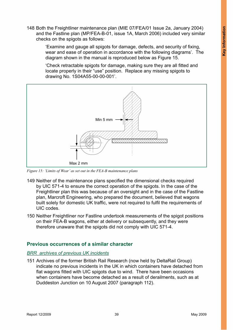
Report 12/2009 39 May 2009
Figure 15: ‘Limits of Wear’ as set out in the FEA-B maintenance plans
Max 2 mm
Min 5 mm
148 Both the Freightliner maintenance plan (MIE 07/FEA/01 Issue 2a, January 2004) and the Fastline plan (MP/FEA-B-01, issue 1A, March 2006) included very similar checks on the spigots as follows:
‘Examine and gauge all spigots for damage, defects, and security of fixing, wear and ease of operation in accordance with the following diagrams’. The diagram shown in the manual is reproduced below as Figure 15.‘Check retractable spigots for damage, making sure they are all fitted and locate properly in their “use” position. Replace any missing spigots to drawing No. 1S04A55-00-00-001’.
149 Neither of the maintenance plans specified the dimensional checks required by UIC 571-4 to ensure the correct operation of the spigots. In the case of the Freightliner plan this was because of an oversight and in the case of the Fastline plan, Marcroft Engineering, who prepared the document, believed that wagons built solely for domestic UK traffic, were not required to fulfil the requirements of UIC codes.
150 Neither Freightliner nor Fastline undertook measurements of the spigot positions on their FEA-B wagons, either at delivery or subsequently, and they were therefore unaware that the spigots did not comply with UIC 571-4.
Previous occurrences of a similar characterBRR archives of previous UK incidents151 Archives of the former British Rail Research (now held by DeltaRail Group)
indicate no previous incidents in the UK in which containers have detached from flat wagons fitted with UIC spigots due to wind. There have been occasions when containers have become detached as a result of derailments, such as at Duddeston Junction on 10 August 2007 (paragraph 112).
Key
Info
rmat
ion

Report 12/2009 40 May 2009
152 There was an incident involving container detachment at Scorton near Preston in February 1969. Winds there had been gusting to 39 – 46 mph (63 – 74 km/h) on a 4 metre high embankment. The affected train was travelling at a speed of 70 mph (113 km/h) when an empty 30 ft container, weighing 2.2 tonnes broke free of its fastenings and rolled off the train across the down line and came to rest at the foot of the embankment. The fastenings consisted of now obsolete clamps operated by an air-pressurised piston. The clamping gear was subsequently found to be operating correctly. The inquiry at the time attributed the incident to high winds.
153 Brief details of another incident in the 1980s came to light in which containers and motor vehicles (unspecified numbers) were blown off flat wagons traversing Ribblehead Viaduct in Yorkshire. Subsequently, containers were positively held down with twistlocks and container carrying freight trains were prevented from regular use of the viaduct.
Data from SMIS154 Data on UK incidents involving spigots was provided by the RSSB using the UK
railway industry’s Safety Management Information System (SMIS). The search covered the period from January 1998 to September 2008. There were no incidents recorded involving whole containers becoming fully or partially detached in high wind conditions.
British Rail Research archives of incidents on other European railways155 In 1990 the ORE C179 Committee sent out a questionnaire to 23 European
railway organisations to obtain information on the nature and causes of aerodynamics related incidents with the objective of taking measures to reduce them. Amongst the responses, ten railways reported an average of one incident per year involving the displacement of loads in high winds. These incidents involved empty containers, swapbodies, caravans or loss of fine particulate loads. Sweden reported a number of cases of empty containers being blown off wagons, but found that these were due to faulty securing devices (type unspecified). Ireland had a similar experience for the same reason. BR reported the Ribblehead Viaduct incident above.
156 As part of the aerodynamic studies relating to the operation of freight wagons through the Channel Tunnel and the safety of containers restrained by UIC spigots, BR held discussions with German Railways (DB) in the late 1980s. DB reported only one incident of container loss from a flat wagon with UIC spigots. The incident occurred on an embankment with a train speed of about 75 mph (121 km/h), but no other details were provided. Investigation of the event showed that the spigots were out of tolerance, but it is not clear whether this related to the spigot shape or lateral spacing. Other containers on similar wagons in the train, with spigots that were in tolerance, were not affected by the winds. DB’s opinion was that the manufacturing specification and tolerances of the spigot must be strictly adhered to for their successful operation. DB had noted wear problems with spigots, however no special action had been taken to remedy it. Every six years, flat wagons were overhauled at which time any worn spigots would be routinely replaced.
Key Inform
ation

Report 12/2009 41 May 2009
157 There was also an incident in early 1993 when an international freight train lost two containers, one from French Railways (SNCF) and the other from German Railways (DB), in Germany. The containers were about 1.7 tonnes in weight, but no other details are available. One loss was attributed to wear of the spigots, but the reason for the other was not stated. Following this incident, SNCF started lashing containers down and monitoring the wind speed. Meanwhile DB introduced train speed reductions and cessation of services depending on the severity of the wind.
158 The archives also contained details of two incidents of container loss on SNCF which were reported to BR representatives at a meeting on 4 August 1992. The two incidents occurred in relatively unexceptional winds in the Perpignan area of France, normally renowned for strong winds, on 4 April and 18 April 1992. The containers were empty and weighed 3.3 tonnes and 4.2 tonnes. Both containers were being carried on a “skeletal bogie wagon”. During subsequent inspection of the wagons, it was discovered that only two of the four required spigots were engaged on each wagon and the incidents were attributed to operational problems.
Information from the UIC via Network Rail159 Following the incidents at Cheddington and Hardendale, Network Rail obtained
the following additional information from UIC members. 160 Spanish Railways had an incident about ten years ago near Valencia when
a container blew off a wagon in high winds and fouled an adjacent line. The detached container was detected by track circuits and a collision with a high speed train which was approaching the area at the time, was averted.
161 SNCF reported they have had a few incidents related to the retention of empty containers due to wind in coastal areas. No further details were provided. Specific measures to secure containers with wires are in place in certain areas when high winds are forecast.
162 Austria, Switzerland, Belgium and Denmark reported they had not had similar incidents. Denmark has speed restrictions in place for container traffic over two long bridges, the Great Belt bridge and the Øresund bridge. These restrictions start at wind speeds of 25 metres/sec (56 mph) and 21 metres/sec (47 mph) respectively for the two bridges. Above 30 metres/sec (67 mph) and 34 metres/sec (76 mph) respectively, no trains are allowed on the bridges.
Information from ORE B112 report RP7 (Oct 1973)163 An incident in Italy was reported involving 12 large containers but there were no
securing devices except low stanchions. The date of the incident was not stated.
Key
Info
rmat
ion

Report 12/2009 42 May 2009
Analysis
Identification of the immediate cause6 164 The immediate cause of the container detachments at both Cheddington and
Hardendale was the aerodynamic forces acting on the containers which resulted from a combination of the cross winds at those locations and the train speed at the time.
165 The resultant wind speeds at mid-container height on the embankments were between 3 and 16% greater than the overturning speeds for unrestrained, empty 20 ft and 40 ft box containers (paragraph 96).
Identification of causal7 and contributory8 factorsThe cross wind conditions166 The wind conditions measured at the remote weather monitoring sites closest
to the incident sites at Cheddington and Hardendale were toward the top end of wind speeds normally measured close to those locations (paragraph 85) but they were not exceptional. Had the cross wind speeds at both sites been less severe or been more aligned with the track, the incidents would not have happened and therefore the particular wind conditions at the times of the incidents were causal factors.
167 The maximum cross wind gust speeds at mid-container height were estimated at 48.8 mph (78 km/h) for Cheddington and 64.1 mph (103 km/h) for Hardendale (paragraph 83). Both these values, which take into account the effect of the embankments, are lower than the minimum cross wind speed in which freight vehicles are designed to operate without overturning, of 31 metres/sec (112 km/h) or approximately 70 mph (paragraph 89). They are also lower than Network Rail’s minimum gust wind speed trigger level of 69 mph (111 km/h) for speed restrictions on the network when the gusts are not sustained for longer than 4 hours, as was the case at both incident sites (paragraph 84).
6 The condition, event or behaviour that directly resulted in the occurrence7 Any condition, event or behaviour that was necessary for the occurrence. Avoiding or eliminating any one of these factors would have prevented it happening.8 Any condition, event or behaviour that affected or sustained the occurrence, or exacerbated the outcome. Eliminating one or more of these factors would not have prevented the occurrence but their presence made it more likely, or changed the outcome.
Analysis

Report 12/2009 43 May 2009
168 It is likely that the gusts speeds seen by the trains were even higher than indicated by the remote measurements and very variable for the following reasons:l The first 20 ft box to overturn at Hardendale detached at a point where the
surrounding land is almost level with the track and there would have been no embankment effect. The calculations indicate the probability of overturning at this location was marginal.
l A 20 ft tank also overturned at Hardendale. As this weighed 4 tonnes and is more streamlined than a 20 ft box type container, which typically weighs 2.3 tonnes, it would need a greater gust speed to overturn it.
l Some other empty containers on the FEA-B wagons on both train 4E90 and 4S83 did not detach.
The effect of the embankments169 Both incidents occurred on embankments which have the effect of accelerating
the wind locally as it flows over them; there being zero acceleration factor for level ground and a 1.3 factor for a 7 metre high embankment (Appendix E). The absence of an embankment at the southern end of the Hardendale site did not prevent a container detaching there. The presence of the embankments was therefore a contributory factor.
The speed of the trains170 Both trains were running at their maximum permissible speed (paragraphs 77,
78) of approximately 75 mph (121 km/h). The forward motion of the train generates a wind over the containers parallel to the track, which combines with the cross wind giving a resultant that lies at an angle to the track. The higher the train speed the greater is the magnitude of the resultant wind. Whether or not a container overturns is dependent on both the magnitude and angle of the resultant wind. Had the trains been running at a lower speed, the resultant wind would have been less than the container overturning wind speed and the containers would not have become detached. Therefore, the train running speeds was a causal factor in each incident.
The unladen state of the containers171 None of the loaded containers on the two trains detached. Had the containers
which blew off been loaded, there would have been sufficient weight to counteract the overturning forces applied by the wind conditions. The empty state of the containers was therefore a causal factor but it is also a normal condition since freight containers are often transported when empty.
Exposed container underframes172 The FEA-B wagon has a central spine with outriggers at the spigot locations
(Figure 5). Between the outriggers, the width of the spine is less than half the width of a container and therefore the container overhangs the flat frame of the wagon except at the outrigger positions. On a conventional wagon with a full width underframe, less of the container’s bottom surface is exposed.
Ana
lysi
s

Report 12/2009 44 May 2009
173 The overhanging parts of containers are directly exposed to air flowing upwards off steep embankments. This could have generated additional lift forces on the windward side from the vertical component of air flow acting directly on the containers, which may have exacerbated the overturning effect from the horizontal component of the wind speed. The exposure of the containers to vertical components of air flow on the spine type design of wagon is therefore considered a possible contributory factor.
The lack of overturning restraint for the containers174 The spigots locating the detached containers showed no significant signs of
distress which indicated that the containers had lifted and/or rolled off the wagons relatively easily. None of the empty containers on other flat wagons fitted with twistlocks became detached. This indicated that the containers on the FEA-B wagons had not been adequately secured. Subsequently, this was verified by testing and analysis (paragraphs 120, 122). The lack of overturning restraint on the FEA-B wagons was a causal factor in both incidents.
175 The lack of overturning restraint arose from two design faults. The first design fault was the unusual use of an inboard hinge on the fold-down spigot design. In the absence of any additional locking to the wagon frame, the inboard hinges allowed the windward spigots to rotate in the same sense as the overturning containers and this prevented any effective restraint. Inward rotation of a fold-down spigot is effectively precluded in UIC 571-4 appendix C by the specification of a maximum 2 degrees of inward tilting of the spigot, relative to the wagon frame.
176 The second design fault was that the lateral spacing of the spigots was based on the value specified in UIC 571-4 appendix A of 2259 +/- 2mm between spigot centres, intended for use with fixed spigots. The spigot spacing should have been set to the value in UIC 571-4 appendix C of 2265 +1/-0 mm between pocket centres, which is required for fold-down spigots, to account for the lateral clearances in the deployed position. This resulted in the lateral spacing of the spigots being closer than is required to ensure load security (paragraph 116).
177 If the first design fault had not existed, the effect of the second design fault on container retention would have depended on the lateral spacing of the corner castings on individual containers as well as the tolerances of the spigot heads and pockets in the wagon frame. If the corner casting spacing was at the wide end of the tolerance band, then the container may not be able to slide across and bear against the windward spigot first in order to prevent overturning. If the corner casting spacing is towards the narrower end of the tolerance band, then restraint may still have been achieved if the first design fault did not exist. However, it is clearly not a safe situation to have the level of overturning restraint being dependent on the favourable combination of the several tolerances involved.
178 There were several reasons why the design faults on the FEA-B wagons occurred: l Greenbrier reported they did not appreciate that UIC spigots were designed to
restrain overturning of containers in windy conditions (paragraph 131). Had they done so, the RAIB consider that they would almost certainly have designed the spigot to be compliant with UIC 571-4 appendix C. Their lack of knowledge about UIC spigot operation was therefore a causal factor.
Analysis

Report 12/2009 45 May 2009
l There was a lack of explicit warning in UIC 571-4 about using inboard hinges for fold-down spigots and this was a causal factor (paragraph 130).
l Greenbrier reported that there was a lack of clarity in UIC 571-4 as to when the different spacings in appendices A and C should be used (paragraph 119). However, the RAIB consider that the standard is clear that appendix C should always be used for fold-down spigots and the wording of UIC 571-4 in this respect is not considered a contributory factor.
l Greenbrier’s practice on previous wagon designs for Polish and Russian Railways, of using lateral spigot spacings very similar to those specified in appendix A of UIC 571-4, influenced their decision about the spigot spacings to be used on the FEA-B wagons (paragraph 118). Their previous practice was therefore a contributory factor.
l Greenbrier believed that unsecured containers on their FEA-B wagons would be safe from overturning in UK wind conditions. This was based on a calculation they undertook using the minimum intrinsic roll-over wind speed specified in Railway Group Standard GM/RT2142. The calculation did not take account of the train’s forward speed and was an incorrect use of the standard (paragraph 132). This was a contributory factor.
The lack of detection of the spigot faults during the vehicle certification process179 Compliance of the FEA-B spigots with UIC 571-4 was not checked by the VAB
during the vehicle certification process. This was a missed opportunity to find the spigot design faults and therefore a causal factor. This happened for the following reasons.
180 Load retention devices are not addressed in any of the mandatory design Railway Group Standards applicable to freight vehicle certification, against which the VAB is required to check compliance. Had the mandatory standards included load retention devices, the VAB would have carried out compliance checks on the spigots and would almost certainly have discovered the spigot design faults. The lack of a mandatory requirement for load retention devices was therefore a causal factor.
181 Had the VAB recognised the novelty of the inboard hinge spigot design on the FEA-B wagon and taken cognisance of the guidance in document GM/GN 2589 (paragraph 138), attention would have been drawn to both Railway Group Standard GO/RM3056 and UIC 571-4. Compliance checks against these standards would almost certainly have led to detection of the spigot design faults. In the event, the VAB assumed that the spigots were compliant to UIC 571-4 as stated by the manufacturer. Not following the advice in GM/GN2589 was a causal factor.
The lack of detection of the spigot faults in service182 The freight operators involved did not identify that the inboard hinges on the
FEA-B fold-down spigots could not provide overturning retention for containers, either when they took delivery or subsequently during operational service. Therefore, they could not meet the load security requirements of Railway Group Standard GO/RM3056. The lack of identification was a causal factor.
Ana
lysi
s
Report 12/2009 46 May 2009
183 The dimensional checks specified in UIC 571-4 had not been included in the wagon maintenance plans (paragraph 149) and therefore the spigot design faults went undetected during operational service. Had the checks been made, they would have identified that the spigot spacings were not compliant and this in turn may have led to identification of the hinge design fault. Therefore the lack of maintenance checks during service operation against UIC 571-4 was a possible causal factor.
184 The freight operating companies believed that the wagon spigots were compliant to UIC 571-4, as declared by the vehicle manufacturer in their technical specification for the FEA-B wagons. This was a contributory factor. Their assurance of this also went forward to HMRI who approved the wagons on the basis that UIC spigots were well established in the UK by that time.
Identification of underlying causes9
185 There was a lack of industry awareness prior to the incidents about the design, operation and maintenance requirements of UIC spigots. Freight operators appeared to have lost the understanding acquired by BR when UIC spigots were first introduced to the UK (paragraph 102) about the way UIC spigots are designed to work and the importance of maintaining critical dimensions within the specified tolerances in UIC 571-4.
186 There was a general perception that UIC standards are not applicable to UK rolling stock unless mandated in the Railway Group Standards, even if a particular type of rolling stock included components designed to UIC standards. Therefore the certification process was confined to mandatory Railway Group Standrds and did not look wider to the scrutiny of safety-related components designed to non-RGS standards. For spigots on future wagons, this is now addressed by the Freight Wagon Technical Specification for Interoperability (TSI) which came into force in January 200710 (paragraph 190). However, where modifications are made to existing wagons, these will still be covered by Railway Group Standards and not the TSI and therefore omission of the UIC code could still occur.
Severity of consequences 187 The detached containers at both Cheddington and Hardendale blocked running
lines, and despite the presence of another train in the vicinity of Hardendale (paragraph 50), there was no collision with the containers. Had such a collision occurred, the consequences could have been much more serious. The risk of a collision was reduced by two factors:l there were very few passenger trains running in either area at the time,
although there were other freight trains; andl signs of problems at both sites were received by remote controlling centres
and actions were taken by Network Rail to prevent trains entering the affected sections of track.
9 Any factors associated with the overall management systems, organisational arrangements or the regulatory structure.10 ‘Rolling Stock – Freight Wagons’, TSI, Official Journal of the European Union, 28 July 2006, L344
Analysis
Report 12/2009 47 May 2009
188 The severity of the damage at Hardendale led to multiple warning signs of an incident in the area. The area is fitted with track circuits and several of these either showed occupied or faults after the passage of 4S83. The signaller took appropriate action by setting signal CE151, north of the incident site on the Up line, to danger, which protected the southbound sleeper train 1M16 which was approaching the site.
189 At Cheddington, where the track is fitted with axle counters (paragraph 39), the only sign of a problem was the tripping of several OLE sections, identified by the ECR. The ECR operator attempted a reset (as he is permitted to do before undertaking an investigation, under Network Rail procedures) and found that one of the OLE sections could not be reset. This led to a discussion between the ECR and the signaller and the subsequent use of a passenger train to examine the line and the discovery of the containers. Had the ECR been able to reset the OLE, protection measures may not have been put in place.
Observations 190 Since the design of the FEA-B wagon, the Freight Wagon Technical Specification
for Interoperability (TSI) has come into force and is now a mandatory standard for all new wagons including those carrying containers. This standard incorporates elements of UIC 571-4, in particular the spigot spacings, making it clear which apply to fixed spigots and which apply to fold-down spigots. Whilst this should eliminate any future confusion about which spacing to apply to new wagon designs, the TSI does not provide any explicit warnings about the use of inboard hinges for fold-down spigots.
191 Following the first signs of an incident near Cheddington, passenger train 2K03 was requested by the signaller to assist by checking the line (paragraph 44). The signaller asked the driver to “have a look” to see if there was anything between Tring and Leighton Buzzard. The driver of 2K03 accelerated away and drove the train at between 45 and 63 mph (72 – 101 km/h). At these speeds and given the darkness, the driver would probably not have been able to bring the train to a stop before an obstruction on the line. Local investigation by the train operator revealed there had been a misunderstanding between the signaller and the driver regarding the nature of the request to check the line. The signaller did not specifically instruct the driver to “examine the line” and travel at a speed of no more than 20 mph (32 km/h) as required by module AC3 of the Rule Book. The driver did not repeat the message back and a clear understanding of what was required was not reached. Local action was taken to re-brief the driver and signaller on safety critical communications.
Ana
lysi
s

Report 12/2009 48 May 2009
Conclusions
Immediate cause 192 The immediate cause of both incidents was the overturning and detachment from
their wagons, of empty, unsecured freight containers, due to the aerodynamic forces resulting from a combination of high cross winds and train speeds.
Causal factors 193 The causal factors were:
a. the high, but not exceptional, cross wind speeds at both sites (paragraph 166);b. both trains were travelling at close to their permitted maximum speed of
75 mph or 121 km/h (paragraph 170 and Recommendation 1);c. the containers which detached were empty (paragraph 171 and
Recommendation 1);d. the lack of overturning retention provided by the FEA-B wagon’s fold-down
spigots because they had not been designed in accordance with UIC 571-4 appendix C (paragraphs 175, 176 and Recommendations 3, 5 and 6);
e. the wagon manufacturer had not appreciated the function and operating principles of UIC spigots (paragraph 178 and Recommendations 5 and 6);
f. there is a lack of explicit warning in UIC 571-4 about the use of inboard hinges for fold-down spigots (paragraph 178 and Recommendations 5 and 6);
g. compliance of the FEA-B spigots with UIC 571-4 was not checked by the VAB during the vehicle certification process (paragraph 179);
h. lack of a requirement relating to load retention devices in mandatory design Railway Group Standards (paragraph 180 and Recommendation 6);
i. the VAB did not follow the guidance in GM/GN2589 which drew attention to load retention devices and UIC 571-4 in particular (paragraph 181 and Recommendation 6); and
j. the freight operating companies involved did not identify that the inboard hinges of the FEA-B spigots could not provide overturning retention (paragraph 182 and Recommendation 2).
194 A possible causal factor was: l Dimensional checks specified in UIC 571-4 had not been included in the wagon
maintenance plans and therefore checks on the spigot spacings were not undertaken during operational service (paragraph 183, Recommendations 2 and 4).
Concusions

Report 12/2009 49 May 2009
Contributory factors195 The following factors were contributory:
a. the embankments at both sites increased the local cross wind speeds acting on the containers (paragraph 169 and Recommendation 1);
b. the wagon manufacturer believed that unsecured containers on the FEA-B wagons were not at risk of overturning in UK wind conditions. This belief was based on an incorrect interpretation of Railway Group Standard GM/RT2142 (paragraph 178);
c. the wagon manufacturer’s previous experience of satisfactory container security using the nominal spacings in UIC 571-4 appendix A, as used for the FEA-B wagons, reinforced his conviction that there was no deficiency in load security on FEA-B wagons (paragraph 178);
d. the freight operating companies believed that the wagon spigots were compliant with UIC 571-4, as declared by the vehicle manufacturer’s technical specification (paragraph 184); and
e. a possible contributory factor was the partial exposure of the bottom surfaces of the containers on the windward side to the air flowing up the embankment slope which may have increased the lift forces on the containers (paragraph 173 and Recommendation 1).
Underlying causes 196 There has been a loss of UK rail industry awareness and understanding about the
design, operation and maintenance requirements of UIC spigots (paragraph 185 and Recommendation 6).
197 The certification process was confined to mandatory Railway Group Standards, and did not look wider to the scrutiny of safety critical items designed to non-RGS standards (paragraph 186 and Recommendation 7).
Additional observations 198 Network Rail’s wind trigger levels and actions are not specifically aligned with
the critical vehicle roll-over speed specified in GM/RT2142 and, being based on data from monitoring stations remote from the track, do not take into account the effect of local topographical features such as embankments (paragraph 90 and Recommendation 8).
199 The minimum container weight specified in Railway Group Standard GO/RM3056/J, is 1.6 tonnes, irrespective of container size. However, the aerodynamic forces acting on containers in windy conditions are dependent on container size and therefore rules for the minimum container weights on the railways should be specified in relation to size(s) of container (paragraph 80 and Recommendation 9).
200 Greenbrier is reviewing its calculations on whole vehicle overturning due to wind, as specified in Railway Group Standard GM/RT2142 (paragraph 134 and Recommendation 10).
Con
clus
ions

Report 12/2009 50 May 2009
Actions reported as already taken or in progress relevant to this reportNIR 2350201 On 6 March 2008, following tests to confirm that FEA-B spigots did not provide
overturning restraint for containers, Freightliner issued National Incident Report (NIR) 2350 to alert the industry about the incidents at Cheddington and Hardendale and to highlight the discovery of design flaws in the FEA-B spigots. The NIR recommended that above forecast wind speeds of 80 mph (129 km/h), empty containers should not be carried on FEA-B wagons.
202 Further NIRs were issued by Freightliner on 7 March and 25 April 2008 and the latter proposed reduced wind speed triggers for container traffic, which form the current operational requirements for container carrying trains, as follows:l Forecasts of winds over 55 mph (88 km/h): speed restriction of 60 mph
(96 km/h) if empty containers are being carried in forecast area.l Forecasts of winds over 65 mph (105 km/h): no empty containers are allowed
but the train can carry loaded containers at normal line speed.
RAIB Urgent Safety Advice203 On 27 June 2008, in the light of further findings, the RAIB issued urgent safety
advice to alert all freight duty holders that:l non-FEA-B wagons had also been found with non-compliant spigots;l outboard hinge spigots had been found which tilted inwards by more than UIC
571-4 permits, due to excessive play in the hinges; andl there was evidence of non-compliance of some fixed spigots on non-FEA-B
wagons.204 Freight operators were advised to:
l measure or check (e.g. with go/no-go gauges) UIC spigots on their wagons and determine the level of compliance of each wagon and document this;
l implement physical and/or operational safeguards as necessary and appropriate to their fleets, to prevent recurrence of the incidents of 1 March 2008; and
l inform the infrastructure manager of the findings from the surveys and the proposed safeguards.
Industry actions205 Freight operators running wagons fitted with UIC spigots have been developing
procedures for checking their fleets and undertaking measurements of the spigots to check compliance against UIC 571-4. By September 2008, approximately 10-20% of fleets had been checked and results indicated widespread non-compliance beyond the FEA-B fleets. The measurement of wagon spigots is ongoing.
Actions reported as taken or in progress relevant to this report

Report 12/2009 51 May 2009
206 Freightliner are now using locking pins with the UIC spigots on their FEA-B wagons in order to secure empty containers when wind speeds are in excess of 55 mph (88 km/h). These pins have been distributed to their freight terminals and when fitted to empty containers on FEA-B wagons, the restrictions in NIR 2350 will not apply.
207 Network Rail are currently developing a system for improved weather monitoring, including wind, on a real time basis using live data from weather stations from various agencies. The objective is to collate the information and make it available to railway operators via a website to inform operational decision making during adverse weather.
208 RSSB is addressing a consistent approach to the application of standards for freight wagon design, by calling up all the requirements contained in the Freight Wagon TSI (which include requirements for UIC spigots), within the next revision of Railway Group Standard GM/RT2100. They also propose to clarify the requirements for fold-down spigots in supporting guidance to that standard. A guidance note on freight train operation is also under development, and RSSB are considering including a section providing additional guidance to freight operators on the need to consider minimum container weights and safeguards such as speed restrictions, additional securing devices and the use of non-spine type wagons, in certain weather conditions.
Act
ions
repo
rted
as
take
n or
in p
rogr
ess
rele
vant
to th
is re
port

Report 12/2009 52 May 2009
Recommendations
209 The following safety recommendations are made11:
Recommendations to address causal and contributory factors1 Freight Operating Companies running wagons fitted with non-compliant
UIC spigots, should review the threshold speeds in NIR 2350 above which special measures are taken when conveying empty or lightweight containers in windy conditions and check that the following factors are taken into account: l local wind acceleration effects due to topography, on routes they
cover;l minimum container weights and container sizes being transported;
and;l design of the wagons used (e.g. conventional or spine type
underframe).(paragraphs 193b, 193c, 195e).
2 Freight Operating Companies running wagons fitted with UIC spigots should check that the spigots comply with UIC 571-4 and ensure non-compliant wagons are identified for special operational measures when carrying empty or lightweight containers in windy conditions. Particular attention should be given to the lateral spacing and the inward angular rotation of the spigots (paragraphs 193j, 194).
3 Freight Operating Companies running wagons fitted with non-compliant UIC spigots, should develop and implement solutions to reliably retain empty or lightweight containers in windy conditions, in order to eliminate the need for special measures in the long term (paragraph 193d).
4 Freight Operating Companies running wagons fitted with UIC spigots should review and, where necessary, amend their maintenance instructions for spigots to comply with the service checks specified in UIC 571-4 appendix C (paragraph 194).
continued
11 Those identified in the recommendations, have a general and ongoing obligation to comply with health and safety legislation and need to take these recommendations into account in ensuring the safety of their employees and others. Additionally, for the purposes of regulation 12(1) of the Railways (Accident Investigation and Reporting) Regulations 2005, these recommendations are addressed to the Office of Rail Regulation to enable it to carry out its duties under regulation 12(2) to:
(a) ensure that recommendations are duly considered and where appropriate acted upon; and (b) report back to RAIB details of any implementation measures, or the reasons why no implementation
measures are being taken.Copies of both the regulations and the accompanying guidance notes (paragraphs 167 to 171) can be found on RAIB’s website at www.RAIB.gov.uk.
Recom
mendations

Report 12/2009 53 May 2009
5 The Office of Rail Regulation should make a proposal to the European Rail Agency to clarify the section on spigots in the freight vehicle TSI so that wagon designers are made aware of the function and operating principles of UIC spigots, and explicit warning is given about the dangers of fold-down spigots with inboard hinges (paragraphs 193d-f).
6 RSSB should make a proposal, in accordance with Railway Group Standards Code, to introduce a requirement for load retention devices so that such devices are checked against their original specification, whether to RGS or not, as part of the vehicle certification process. For the specific case of UIC spigots, explanatory guidance should be provided about the function and operating principle of UIC spigots and the dangers of fold-down spigots with inboard hinges (paragraphs 193d - i, 196).
7 RSSB should make a proposal to its stakeholders to review whether the implementation of the vehicle certification process in the UK adequately addresses risk introduced by new or refurbished vehicles. This review should include the scrutiny of safety critical equipment designed and built to non-Railway Group Standards (e.g. UIC codes). If necessary, RSSB should propose changes in accordance with Railway Group Standards Code to cover any identified gaps and provide guidance to the UK rail industry on retrospective review (paragraph 197).
Recommendations to address other matters observed during the investigation8 Network Rail should review the compatibility of the wind trigger speeds
and durations at which mitigating action is taken on the network, with the overturning wind speed limits specified in Railway Group Standard GM/RT2142, taking account of local wind acceleration effects due to topography, such as embankments (paragraph 198).
9 RSSB should review whether the current minimum container weight of 1.6 tonnes specified in the Railway Group Standard GO/RM3056 section J, adequately accounts for container size with respect to operations in windy conditions, and make a proposal in accordance with the Railway Group Standards Code to make any necessary changes to this or other standards or guidance on freight train operation (paragraph 199).
10 Freight Operating Companies running FEA-B wagons, should review the status of compliance of these wagons against the whole vehicle overturning requirement of Railway Group Standard GM/RT2142 for all relevant container sizes and, if necessary, take appropriate steps to change their operations with these wagons in windy conditions (paragraph 200).
Rec
omm
enda
tions

Report 12/2009 54 May 2009
Appendices
Appendix A - Glossary of abbreviations and acronyms APT Advanced Passenger Train (now obsolete)
BR British Rail
BRR British Rail Research
CAD Computer aided design
CCF Control centre of the future
DB Deutche Bahn (German national railway company)
ECR Electrical control room
EPS Enhanced permissible speed
HMRI Her Majesty’s Railway Inspectorate
NIR National incident report
NRN National Radio Network
NRVCG Network Rail Vehicle Conformance Group
OLE Overhead line equipment
ORE Office of Research and Experiments (of the UIC)
ORR Office of Rail Regulation
OTDR On train data recorder
PPM Planned Preventative Maintenance
RGS Railway Group Standards
RSSB Rail Safety and Standards Board
SNCF Société Nationale des Chemins de fer Français (French national railway company)
TOPS Total Operations Processing System
TSI Technical Specification for Interoperability
UIC Union International Chemins de Fer
VAB Vehicle Acceptance Body
VIBT Vehicle Inspection and Brake Test
WCML West Coast Main Line
Appendices

Report 12/2009 55 May 2009
Appendix B - Glossary of terms All definitions marked with an asterisk, thus (*), have been taken from Ellis’ British Railway Engineering Encyclopaedia © Iain Ellis. www.iainellis.com
Axle counters A track mounted device that accurately counts passing axles. By using an axle counter evaluator to compare the number of axles entering and leaving a block section, the signalling system can determine whether the section is clear or occupied.*
Beaufort scale A system of recording wind speed, devised in 1806, to help sailors estimate the winds by visual observations of the sea state. The scale ranges from 0 (calm) to 12 (hurricane). The Beaufort scale is still used today to estimate wind strengths.
Blow-off A situation where the pantograph of a train loses contact with dewirements the OLE contact wire because the latter is displaced laterally by high winds. It usually results in damage to both the contact wires and the pantograph.
Chain(s) A unit of length, being 66 feet or 22 yards (20.117 metres). There are 80 chains in one standard mile.*
Coefficient of The ratio of the maximum static frictional force between two static friction surfaces in contact (before they start to slide relative to each (Appendix E) other) to the normal contact force between them.
Corner castings The hollow castings at each corner of a standard freight container which have holes on their lower surfaces to permit load securing devices such as twistlocks and spigots to hold the container in place during transit.
Down (line) In a direction away from London or towards the highest mileage.*
Engineering The process whereby conformance of railway vehicles to the acceptance mandatory requirements of Railway Group Standards is (process) scrutinised and certificated.
Enhanced The increased maximum speed for tilting trains which is above permissible speed the normal permissible speed at which non-tilting trains are permitted to run.
Emergency An interruption to the traction electricity being supplied to a isolation particular part of the overhead line equipment (OLE), undertaken in an emergency. Once an emergency isolation has been carried out the OLE becomes safe to approach but not to touch, as it may still contain a small residual potential.
Heel blocks Metal blocks fitted between the switch rail and stock rail at the switch heel to maintain the correct geometry and prevent longitudinal movement of the switch rail.*
Interlocking Controls, fitted between points and signals that prevent the signaller from setting conflicting routes.*
App
endi
ces
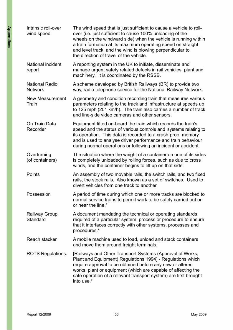
Report 12/2009 56 May 2009
Intrinsic roll-over The wind speed that is just sufficient to cause a vehicle to roll-wind speed over (i.e. just sufficient to cause 100% unloading of the wheels on the windward side) when the vehicle is running within a train formation at its maximum operating speed on straight and level track, and the wind is blowing perpendicular to the direction of travel of the vehicle.
National incident A reporting system in the UK to initiate, disseminate and report manage urgent safety related defects in rail vehicles, plant and machinery. It is coordinated by the RSSB.
National Radio A scheme developed by British Railways (BR) to provide two Network way, radio telephone service for the National Railway Network.
New Measurement A geometry and condition recording train that measures various Train parameters relating to the track and infrastructure at speeds up to 125 mph (201 km/h). The train also carries a number of track and line-side video cameras and other sensors.
On Train Data Equipment fitted on-board the train which records the train’s Recorder speed and the status of various controls and systems relating to its operation. This data is recorded to a crash-proof memory and is used to analyse driver performance and train behaviour during normal operations or following an incident or accident.
Overturning The situation where the weight of a container on one of its sides (of containers) is completely unloaded by rolling forces, such as due to cross winds, and the container begins to lift up on that side.
Points An assembly of two movable rails, the switch rails, and two fixed rails, the stock rails. Also known as a set of switches. Used to divert vehicles from one track to another.
Possession A period of time during which one or more tracks are blocked to normal service trains to permit work to be safely carried out on or near the line.*
Railway Group A document mandating the technical or operating standards Standard required of a particular system, process or procedure to ensure that it interfaces correctly with other systems, processes and procedures.*
Reach stacker A mobile machine used to load, unload and stack containers and move them around freight terminals.
ROTS Regulations. [Railways and Other Transport Systems (Approval of Works, Plant and Equipment) Regulations 1994] - Regulations which require approval to be obtained before any new or altered works, plant or equipment (which are capable of affecting the safe operation of a relevant transport system) are first brought into use.*
Appendices

Report 12/2009 57 May 2009
Rail Safety and An independent rail industry body which manages the creation Standards Board and revision of certain mandatory and technical standards (RSSB) (including Railway Group Standards) as well as leading a programme of research and development on behalf of Government and the railway industry.
Rule Book Railway Group Standard GE/RT8000, which incorporates most of the rules to be observed by railway staff for the safe operation of the network.
Section A length of track bounded by signals or other control arrangements.
Swapbodies A removable road vehicle body that can be transferred directly to a suitable rail vehicle.*
Track circuit An electrical device using rails in an electric circuit which detects the absence of trains on a defined section of line.
Vehicle Acceptance A body given authority by RSSB to undertake engineering Body acceptance for rail vehicles
Vehicle gauge A drawing or specification which sets out the maximum permissible vehicle and loading dimensions, suspension displacements, and curve overthrows.
Up (line) Moving in a direction toward London.*
App
endi
ces
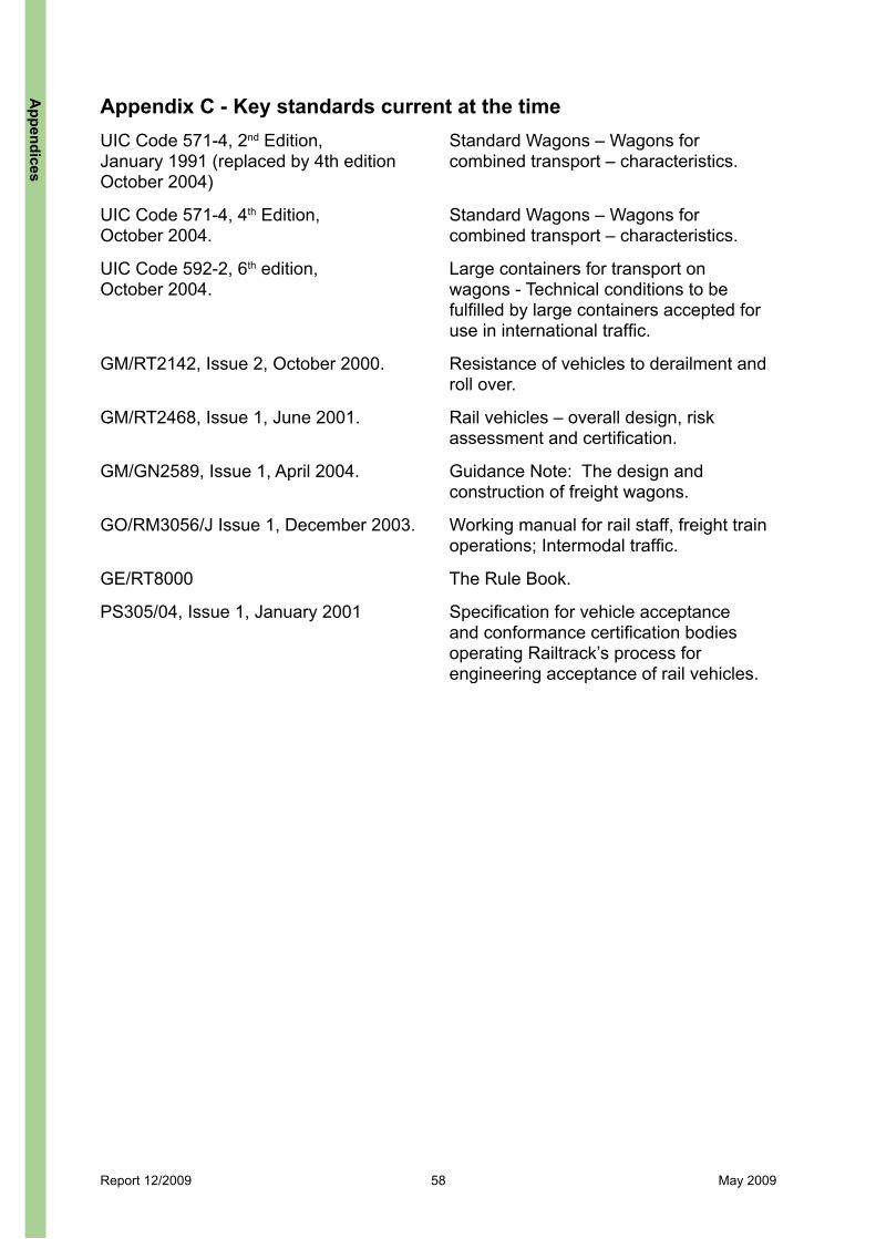
Report 12/2009 58 May 2009
Appendix C - Key standards current at the time UIC Code 571-4, 2nd Edition, Standard Wagons – Wagons for January 1991 (replaced by 4th edition combined transport – characteristics. October 2004)
UIC Code 571-4, 4th Edition, Standard Wagons – Wagons for October 2004. combined transport – characteristics.
UIC Code 592-2, 6th edition, Large containers for transport on October 2004. wagons - Technical conditions to be fulfilled by large containers accepted for use in international traffic.
GM/RT2142, Issue 2, October 2000. Resistance of vehicles to derailment and roll over.
GM/RT2468, Issue 1, June 2001. Rail vehicles – overall design, risk assessment and certification.
GM/GN2589, Issue 1, April 2004. Guidance Note: The design and construction of freight wagons.
GO/RM3056/J Issue 1, December 2003. Working manual for rail staff, freight train operations; Intermodal traffic.
GE/RT8000 The Rule Book.
PS305/04, Issue 1, January 2001 Specification for vehicle acceptance and conformance certification bodies operating Railtrack’s process for engineering acceptance of rail vehicles.
Appendices

Report 12/2009 59 May 2009
Appendix D - Wagon formations for 4E90 and 4S83 Notes: Container size in ft length (standard notation).Container weights as per TOPS list; E= empty, L = laden.Containers coloured red are those that detached in the incidents.
Train 4E90 hauled by locomotive 56301 (Cheddington)
Train 4S83 hauled by locomotives 88621 & 88638 (Hardendale)
Wagon ContainerSize (ft)
Containerweight (tonnes)
Wagon ContainerSize (ft)
Containerweight (tonnes)
- - 20 2.0 (E) - -1. FEA-B
643004 - -
1. FSA 608453 40 14.0 (L)
20 2.3 (E) 20 2.3 (E)
40 5.0 (E)2. FEA-B 643003
20 2.2 (E)
2. FSA 608397
20 2.0 (E) 20 8.4 (L) 20 4.0 (E)
20 2.0 (E)3. FEA-B 643002 40 16.9 (L)
3. KFA 93482
20 2.0 (E) - - 20 2.0 (E)- -4. FEA-B
643001- -
4. KFA 93369 40 12.0 (L)
- - 20 2.0 (E)20 7.6 (L)5. FEA-B
643020- -
5. FSA 608302 40 5.0 (E)
- - 20 2.0 (E)- -6. FEA-B
643019- -
6. FSA 608303 40 15.7 (L)
- -- -7. FEA-B
643024- -
7. FEA-B 640203 40 5.0 (E)
- - 20 2.0 (E)- -8. FEA-B
643023- -
8. FEA-B 640204 40 5.0 (E)
- -- -9. FEA-B
643017- -
9. FEA-B 640275
- -- -10.FEA-B
643018- -
10.FEA-B640276
- -- -11. FEA-B
643012- -
11. FEA-B 640106
- -- -12. FEA-B
643011- -
12. FEA-B 640105
- -- -13. FEA-B
643014- -
13. FSA 608239
- -- -14. FEA-B
643013- -
14. FSA 608240
App
endi
ces

Report 12/2009 60 May 2009
Train 4E90 hauled by locomotive 56301 (Cheddington)
Train 4S83 hauled by locomotives 88621 & 88638 (Hardendale)
Wagon ContainerSize (ft)
Containerweight (tonnes)
Wagon Container Size (ft)
Containerweight (tonnes)
- -- -15. FEA-B
643010- -
15. FSA 608468
- -- -16. FEA-B
643009- -
16. FSA 608515
- -- -
40 5.0 (E)17. FEA-B 643021
- -
17. FEA-B 640295
- - 20 2.0 (E)- - 20 4.0 (E)18. FEA-B
643022- -
18. FEA-B 640296
20 2.0 (E) - - 20 2.0 (E)- - 20 13.0 (L)19. FEA-B
643006- -
19. FEA-B 640243
20 (tank) 4.0 (E) - - 20 2.0 (E)- - 20 14.0 (L)20. FEA-B
643005- -
20. FEA-B 640244
20 2.0 (E)
Appendices

Report 12/2009 61 May 2009
Appendix E - Overturning of containers In order to determine whether the wind conditions at Cheddington and Hardendale were severe enough to have caused an empty, unrestrained, container to overturn, estimates of the wind speeds likely to have been acting on the containers must be made and compared with the critical wind speed above which overturning would be expected. Separate evaluations were made for the conditions at Cheddington and those at Hardendale as summarised below. Estimate of local wind speeds and directions at incident sitesThere were no measuring stations at the incident sites and therefore the local wind conditions had to be estimated from measurements made by nearby monitoring stations. Data was provided to RAIB by Vaisala Ltd. The nearest weather station to the Cheddington incident is approximately 6 km away on the A418 near Wing. An anemometer located there, at a height of 10 metres, provided data on mean wind speeds at 5 minute intervals. The nearest weather station to the Hardendale incident is approximately 2.5 km away to the southeast adjacent to the M6 at Shap Summit. An anemometer located there at a height of between 4 and 4.5 metres provided mean wind speed and max 3 sec gust data at 10 minute intervals. Local gust speeds and directions at mid-container height above rail level were estimated from the raw data output from the above stations as follows: The mean wind speed in the hour centred around the incident times was calculated from the raw data. The direction of the wind at the remote monitoring site near Cheddington was westerly. For Hardendale the wind direction was less clear; the closest station recorded north-north-west but was subject to local topographical turning of the prevailing wind. Data on wind direction from other nearby stations, one on the A6 at Shap and the other on the M6 at Tebay, were used to make a best estimate that the wind direction at Hardendale was also likely to have been westerly. The mean wind speeds were converted to ground level gusts using standard methods12,13 for determining wind speeds at a site from reference wind data at another site by applying factors to account for differences in surface roughness, topography, relative heights of the wind measurements and the averaging time of the wind speed required. For these calculations the surface roughness between the sites was assumed constant for each location pair and corrections were applied only to correct for differences in height and the change from hourly mean to 3 second gust wind speeds. The reference height at the incident sites was taken as 3 metres; approximately mid-container height above rail level. The presence of an embankment accelerates the wind such that the local wind speed on top of the embankment is greater than the approach wind speed. These gust speeds at 3 metres height were then converted to gusts speeds at the top of the embankment. Acceleration factors for embankments were taken from Railway Safety Approved Code of Practice GC/RC552114.
12 Strong winds in the atmospheric boundary layer. Part 1: Mean-hourly wind speeds. Engineering Sciences Data Item No. 82026. ESDU, September 1982.13 Strong winds in the atmospheric boundary layer. Part 2: Discrete gust speeds. Engineering Sciences Data Item No. 83045. ESDU, November 1983.14 Calculation of enhanced permissible speeds for tilting trains. Railway Safety Approved Code of Practice, GC/RC5521, June 2001.
App
endi
ces

Report 12/2009 62 May 2009
The calculated wind speeds at each stage of the calculation are given in the table below. The estimated 3 second gust speeds acting at mid-container height at the top of the embankment are shown in bold.
Mean hourly wind speed
Assessed wind direction
relative to track
Calculated 3 sec ground level gust
speed
3 sec gust speed acting on containers
at track level
Cheddington –4 metre embankment
31.2 mph (50.2 km/h)
79 deg. (W) 40.3 mph
(64.8 km/h) 48.8 mph (78 km/h)
Hardendale – level 32.8 mph 52.8 km/h
90 deg. (W) 48.6 mph 78.2 km/h
48.6 mph 78.2 km/h
Hardendale - 7 metre embankment
32.8 mph 52.8 km/h
90 deg. (W) 48.6 mph 78.2 km/h
64.1 mph 103 km/h
Estimate of container sliding, lifting and overturning speedsThe containers were subject to the combined effect of the wind gusts evaluated above and the relative flow due to train speed, taken as 75 mph (121 km/h) for both incident sites. The resultant wind speeds acting on the containers at each location were calculated from the vector sum (i.e taking account of both the magnitude and direction) of the train and cross wind speeds. This resultant wind acts at an angle to the track (the wind angle) which is dependent on the relative magnitudes of the train and cross wind speeds. The critical overturning wind speed for each location and container was calculated using a theoretical model, developed in 1990 by British Rail Research (BRR)15 for determining the overturning wind speed of an unsecured container on a flat wagon. The model was validated against full scale test data measured in Germany by Deutche Bundesbahn in 1989, when an isolated, instrumented and unsecured container was run on a wagon fitted with stanchions, in strong cross winds.The container overturning model described above, was used to determine the wind speeds necessary to:
l slide the container sideways against friction, (assuming a steel to steel coefficient of friction of 0.15);
l aerodynamically lift the containers for the given relative wind angle calculated at the incident sites and;
l overturn the container for the given relative wind angle calculated at the incident sites.
The results obtained from the model are shown in Table E2 (see over).The results from Table E2 show that at each location the wind speed required to slide the container on its wagon is significantly less than the wind speed to overturn it, which in turn is significantly less than the wind speed to aerodynamically lift the container off the wagon.
15 Johnson T, ‘Overturning mechanisms of unsecured containers on DB’, British Rail Research Aerodynamics Note, September 1990.
Table E1: Summary of calculated cross wind speeds (train speed not included)
Appendices
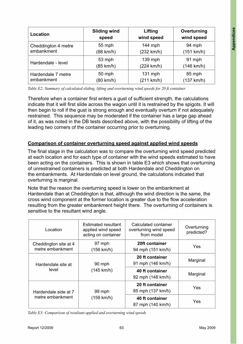
Report 12/2009 63 May 2009
Therefore when a container first enters a gust of sufficient strength, the calculations indicate that it will first slide across the wagon until it is restrained by the spigots. It will then begin to roll if the gust is strong enough and eventually overturn if not adequately restrained. This sequence may be moderated if the container has a large gap ahead of it, as was noted in the DB tests described above, with the possibility of lifting of the leading two corners of the container occurring prior to overturning.
Comparison of container overturning speed against applied wind speedsThe final stage in the calculation was to compare the overturning wind speed predicted at each location and for each type of container with the wind speeds estimated to have been acting on the containers. This is shown in table E3 which shows that overturning of unrestrained containers is predicted at both Hardendale and Cheddington on the embankments. At Hardendale on level ground, the calculations indicated that overturning is marginal.Note that the reason the overturning speed is lower on the embankment at Hardendale than at Cheddington is that, although the wind direction is the same, the cross wind component at the former location is greater due to the flow acceleration resulting from the greater embankment height there. The overturning of containers is sensitive to the resultant wind angle.
LocationSliding wind
speedLifting
wind speed Overturningwind speed
Cheddington 4 metre embankment
55 mph (88 km/h)
144 mph (232 km/h)
94 mph (151 km/h)
Hardendale - level 53 mph
(85 km/h) 139 mph
(224 km/h) 91 mph
(146 km/h)
Hardendale 7 metre embankment
50 mph (80 km/h)
131 mph (211 km/h)
85 mph (137 km/h)
Table E2: Summary of calculated sliding, lifting and overturning wind speeds for 20 ft container
LocationEstimated resultant applied wind speed acting on container
Calculated container overturning wind speed
from model
Overturningpredicted?
Cheddington site at 4 metre embankment
97 mph (156 km/h)
20ft container 94 mph (151 km/h)
Yes
20 ft container 91 mph (146 km/h)
MarginalHardendale site at
level90 mph
(145 km/h) 40 ft container 92 mph (148 km/h)
Marginal
20 ft container 85 mph (137 km/h)
YesHardendale side at 7 metre embankment
99 mph (159 km/h) 40 ft container
87 mph (140 km/h) Yes
Table E3: Comparison of resultant applied and overturning wind speeds
App
endi
ces

This report is published by the Rail Accident Investigation Branch, Department for Transport.
© Crown copyright 2009
Any enquiries about this publication should be sent to:
RAIB Telephone: 01332 253300The Wharf Fax: 01332 253301Stores Road Email: [email protected] UK Website: www.raib.gov.ukDE21 4BA