railcar unloading systems - · pdf fileliquid gases (propane, butane, lpg, ... vapor recovery...
TRANSCRIPT

Railcar unloading systems
www.scherzer.net
Dipl.-Ing. SCHERZER GmbH
LOADING YOUR FUEL

Welcome to Dipl.-Ing. SCHERZER GmbH The company’s field of activities includes the planning and turn-key construction of plants for handling and storing liquid and gaseous products. Based on more than 50 years of experience in these sectors, the company offers a high degree of professional-ism and is a leader in its field.
Our customers from the petroleum and chemical industries and from a range of other sectors at home and abroad value our groundbreaking technology and our high quality standards as well as our ability to address custom applications while optimizing the economic and environmental aspects of our designs.
Quality - Safety - Service Social and environmental policy requirements place high demands on our company on a daily basis, as do constantly changing safety guidelines. These standards are our top priority. Consequently, all areas of the company are subject to a quality management system and certified in accordance with DIN EN ISO 9001:2015.
As a specialized company, we do, of course, have all legal permits necessary to operate both in Germany and abroad.
Our subsidiary, SCHERZER Umwelttechnik GmbH, will handle our after-sales service, allowing us to be there for you long after a successful start-up. Maintenance, the pro-curement of spare parts, and other important services will guarantee the continuous operation of your plant.
Range of services Our comprehensive range of services includes:
Concept design including essential performance characteristics
Basic engineering
Detail engineering
Delivery of equipment
Assembly of unit (for turnkey contracts)
Supervision (for assembly by customer)
Training
Commissioning
Performance check
Documentation and handover
Services
Scope of supplies and services Our portfolio covers a wide range, allowing us to meet almost every requirement. In addi-tion to new construction, it also comprises the retrofit, conversion or expansion of ex-isting plants for the loading and unloading of:
Railcars
Tank trucks
Ships
for transshipment of:
Light products (petrol/gasoline, diesel, jet fuel, etc.)
Dark products (crude oil, bitumen, etc.)
Chemical products (arenes, acids, etc.)
Stable gas condensate
Liquid gases (propane, butane, LPG, etc.)
Biodiesel / Bioethanol
The scope of our services covers also the new construction and reconstruction of tank farms as well as peripheral components and sys-tems such as:
Vapor recovery units (VRU)
Vapor pendulum systems
Fire-fighting systems
Product and pump systems
Drainage systems
Power-supply systems
Automation technology
Control and monitoring systems
Product data logging
Railroad lines
Firmendarstellung:
2

Railcar unloading systems for the emptying of tank railcars in a fully-automatic or semi-automatic process
For more than 50 years, our company group has been engaged in planning and turn-key construction of handling and storage systems for liquid and gaseous products. Our cus-tomers include the mineral oil industry, the chemical industry and a number of other industries.
SCHERZER does not only plan and supply railcar unloading systems, but provides the design for the complete unloading system including all trades, such as automation, load-ing and unloading computer, data logging systems, piping systems, power supply, build-ings etc.
In 1977, the first tanker railcar unloading system was planned and delivered by SCHERZER. Since that time, SCHERZER has planned, delivered and commissioned railcar unloading systems either under a specific contract or in connection with the construc-tion of a tank farm.
One most modern facility is located in a tank farm in Poland (Ostrow Wielkopolskie /ORLEN). This plant is largely operated in a fully automatic way. Opening and closing of the dome, connecting the hose and opening and closing the manual valve on the railcar have to be carried out manually. The complete process up to the full unloading of the railcars is fully automatic. The connecting points are monitored by sensors; the valves and the frequency-controlled pump are controlled and monitored based on the filling level in the tank, using a PLC developed by SCHERZER.
Additional a new railcar unloading facility with a underground tank and a automatic tank discharge system was built in south of Germany by Dipl.-Ing. SCHERZER GmbH as a turnkey project. The advantage of this variant is that no vacuum can occur in the tank wagon. All tank wagons are connected to a underground tank by swivel joint unloading arm and the product is drained into the tank by the altitude difference with a control valve. Forwarding of the product will be handled by frequency controlled pumps de-pending to the tank level. This variant is also subject to the amount of different prod-ucts.
Unloading systems for railcars and the associated automation equipment are designed in accordance with the respective local conditions and the customer’s requirements.
Transfer stations consist of articulated steel tube loading units or hose systems with manual valves or sensor-controlled valves.
Products are filled into the tanks via a combined manifold system using controlled pumps.
The distributor may be emptied after each loading process using a residual discharge system.
3
UNLOADING BY RUBBER TUBES
UNLOADING BY METAL PROTECTIVE TUBE
UNLOADING BY SWIVEL JOINT ARMS
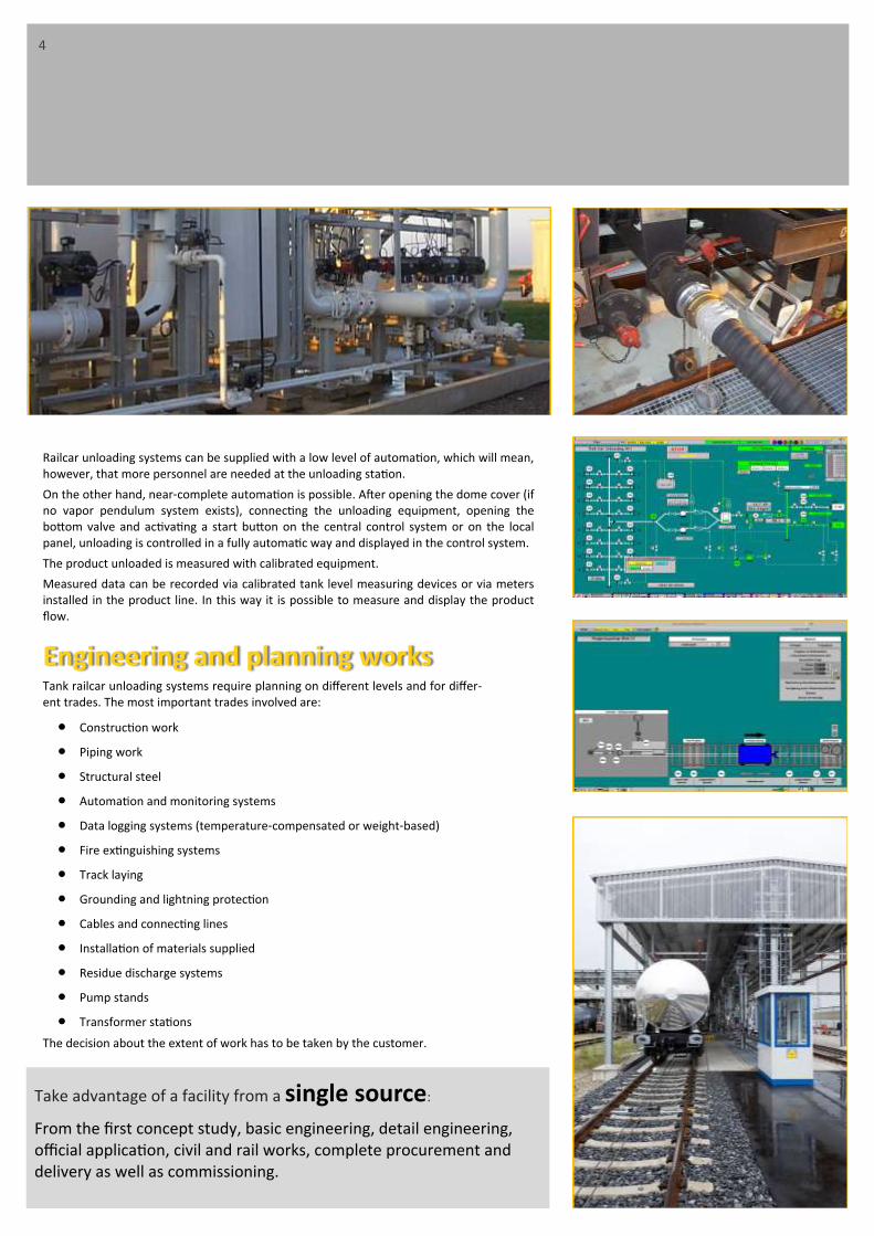
Railcar unloading systems can be supplied with a low level of automation, which will mean, however, that more personnel are needed at the unloading station.
On the other hand, near-complete automation is possible. After opening the dome cover (if no vapor pendulum system exists), connecting the unloading equipment, opening the bottom valve and activating a start button on the central control system or on the local panel, unloading is controlled in a fully automatic way and displayed in the control system.
The product unloaded is measured with calibrated equipment.
Measured data can be recorded via calibrated tank level measuring devices or via meters installed in the product line. In this way it is possible to measure and display the product flow.
Engineering and planning works Tank railcar unloading systems require planning on different levels and for differ-ent trades. The most important trades involved are:
Construction work
Piping work
Structural steel
Automation and monitoring systems
Data logging systems (temperature-compensated or weight-based)
Fire extinguishing systems
Track laying
Grounding and lightning protection
Cables and connecting lines
Installation of materials supplied
Residue discharge systems
Pump stands
Transformer stations
The decision about the extent of work has to be taken by the customer.
4
Take advantage of a facility from a single source:
From the first concept study, basic engineering, detail engineering, official application, civil and rail works, complete procurement and delivery as well as commissioning.

The tasks, related to railcar unloading facilities, performed by SCHERZER require the following relevant design and engineering works:
a) Determination of bases Determining the requirements for the solution of railcar unloading facilities.
Clarifying the tasks for framework planning and stability verifications.
Summarising the results.
Selecting and inspecting similar objects.
b) Preparatory planning Project and planning preparation, analysis of bases.
Investigation of possible solutions for constructive and structural design, expedi-ence, economy with due consideration given to environmental aspects .
Preparation of the planning concept including alternative possible solutions as drawings and evaluation documents.
Revision of the planning concept according to the requirements of the customer and authorities.
Elaboration of the final cost estimates based on final preliminary planning.
Compilation of the results of preparatory planning.
c) Design planning Preparation of the planning concept with due consideration of all specified re-
quirements, with the assistance of other technical parties involved in planning up to the complete design.
Elaboration of the explanatory reports.
Drawings of the overall design.
Preparation of a construction time and cost schedule.
Summarising all design documents.
d) Approval planning Preparation of the documents for the necessary procedures of public law .
Completion and adaptation of the planning documents .
5

e) Execution planning Incorporating the results from approval planning with due consideration given to all
technical requirements and utilising the inputs of other technical parties involved in planning up to the solution ready for execution .
Drawings and calculations of the object with all individual data necessary for execu-tion, including detail drawings in the scales required .
Preparation of the bases for the other technical parties involved in planning and inte-gration of their inputs up to the solution ready for execution .
Continuation of execution planning during the implementation of the object .
f) Construction supervision management Supervision of the local construction supervisors, co-ordination of the technical par-
ties involved in object surveillance, in particular checks for compliance and release of the plans of third parties.
Preparation and monitoring of a schedule (bar diagram).
Subjecting the executing companies under delay.
Acceptance of services and supplies together with the local construction supervisors and other technical parties involved in planning and object surveillance, preparation of a record of the acceptance results.
Application for and participation in the acceptance by authorities.
Handing over of the object including compilation and submission of the required documents, e.g. acceptance reports and test reports.
Preparation of maintenance regulations for the object.
Monitoring the tests of the plant parts and the overall plant for proper functioning.
Listing the statutory periods for warranty claims.
Determination of costs.
Cost controlling.
g) Documentation Compilation of the drawings and calculation results of the tank yard on completion,
As-Built documents.
Compilation of plant certificates, operating manuals, maintenance and repair manu-als as well as approvals of authorities for the operation of the tank yard.
Manuals and release of the overall project.
6

7
Design of unloading systems: The following parameters are defined before the start of planning:
Products Temperature ranges Maximum flow rates Loading times Flange connections Working areas for unloader / hoses
Design of measuring sections and data logging systems For measuring sections, the following parameters are specified before the start of planning:
Products Temperature ranges Maximum flow rates Calibration requirements
for measuring sections Billing of volume VT / weight
Design of piping and valves For piping and valves, the following parameters are specified before the start of planning:
Products Temperature ranges Maximum flow rates Valve systems and types
Design of fire fighting systems The following parameters are specified for fire fighting systems before the start and planning and are required for processing the order:
Fire protection and fire water containment
Fire extinguishing medium Temperature ranges
Design of fail-safe systems For fail-safe systems, the following parameters are specified during the planning phase.
Selection of fail-safe systems Selection of signal systems
Design type (articulated loader / hoses) Fail-safe systems
Flange distances Sampling devices Type of data logging Video systems
Meter systems and types Nominal pressure stages Control valve systems and types Full and empty systems
Nominal pressure stages Flange design Scope of supply and services Acceptance tests
Fire fighting areas Requirements imposed by local fire brigades Acceptance tests Selection of fire protection equipment
Requirements imposed by local authorities Scope of deliveries and services for the
systems
All works performed in the danger zone of the tracks requires a previous careful plan-ning.
This also refers to the railcar unloading facili-ties integrated in the track system. The con-siderations which are necessary for the plan-ning of the work must not only confine them-selves exclusively to the actual execution of the work, they also must take into account the accompanying safeguarding reg-ulations.
Necessary safeguarding regulations are often recognized insufficiently and are not included in the budget.
Before the beginning of the work, essential criteria, such as local difficult conditions, sud-denly turn out not to be taken into account.
This omission then must be cleared with addi-tional effort.

Fire protection and fire water containment Fire fighting attack routes have to be designed and marked in such a way that discharge points can be easily and without obstructions reached by fire fighting and rescue vehi-cles.
For filling and discharge points for flammable liquids, location and width of fire-fighting attack routes shall be specified in accordance with DIN 14 090 taking into account local and operating conditions and in agreement with the authorities in charge of fire-fighting.
For filling points subject to a specific permit, a current fire-fighting plan for structural works in accordance with DIN 14 095 and fire protection regulations in accordance with DIN 14 096 must be in force.
Fire fighting equipment shall be available to fight fire outbreaks. In this context, refer-ence is made to the Regulation ASR A2.2 “preliminaries against fires”.
Selection of fire-fighting equipment Type and extent of fire fighting equipment shall be based on local and operating condi-tions, in particular the filling rate and the hazard class of flammable liquids.
In addition, suitable facilities e.g. fire alarms shall be provided to report the fire to the competent fire brigade. Otherwise the fire fighting system must be such that all hazards can be effectively dealt with.
Depending on local and operational conditions, fire fighting equipment may be station-ary, fully movable or partly movable.
Partly movable fire fighting systems include mobile fire trucks or engines that are equiv-alent to stationary fire-fighting systems with regard to the extinguishing medium rate and storage as well as the alarm concept and the response time.
Fire fighting media include: foam, carbon dioxide, powder and water.
Carbon dioxide and powder may not be introduced under pressure into an explosive atmosphere (e.g. for inertization or testing the fire fighting system), unless specific pro-tection measures have been taken. Reference is made to the regulations BGR 132 issued by the trade associations concerning the avoidance of ignition hazards due to electro-static charges.
Fire water containment The need for fire water containment shall be examined for each individual filling and discharge point in cooperation with the competent fire fighting authority; the contain-ment volume shall be defined if applicable.
Fire water containment facilities are, for instance, not required, if the expected share of fire water and flammable liquids is so low in the case of fire, that it can be absorbed by the existing containment facilities.
8

Equipment for process control systems The entire process is controlled and visualized by process control systems (such as WinCC from Siemens) und PLC systems.
Server/client based process control system with centralized data storage on the basis of Windows operated computer systems
Setting up redundant systems
Process interfacing of PLCs (e.g. Simatic S7 from Siemens) via bus systems (Industrial Ethernet or Profibus)
Integration of tank farm management systems, quantity measurement systems approved by the Board of Weights and Measures and ID card reading systems in the overall design
Connection of tank measuring equipment (e.g. radar level measurement systems) with OPC (OLE for Process Control)
Integration of process signals in the PLCs via standardized field bus systems (Profibus-DP, Profibus-PA)
Interfaces to third-party systems and their integration (to the extent possible) in process automation via standardized or user-specific protocols (e.g. Profibus, Modbus, 3964R, RK512 or others)
SAP interfaces for the loading computer systems and customer-specific adaptations are possible.
Process visualisation Subordinate systems (e.g. railcar filling and discharge points, VRU systems, handling and mixing facilities) will be equipped with subordinate machine-oriented operating and monitoring systems based on Windows-operated computer systems. Visualization and process operation in visualization images designed specifically for this process.
Specification and verification of process parameters
Alarm visualization, alarm logging and alarm archiving
Integration of subordinate process visualization systems in the process control system
Interfaces
Signal exchange with customers
Remote maintenance via telephone
Type and scope of automation
Specification of the automation system (PLC and control systems)
Automation and monitoring systems For automation systems, the following parameters are specified before the start of planning.
9

Environmental protection and safety The following safety parameters are specified before the start of planning.
Type and extent of track ballast protection (spill containment pans, in-situ concrete)
Safety analyses
Requirements derived from TRGS 727/TRGS 2153 , TRBF and authority regulations
Spill containment systems made of in-situ concrete or rail load bearing elements
The collection are inside railcar unloading stations are made by in-situ concrete or as pre fabricated stations / rail load bearing elements.
During handling, filling, production and treatment of hazardous products for the chemi-cal industry, in transfer stations, filling stations or tankfarms as well as locomotive fuel stations it has to be secured that these products are not contaminating groundwater.
Rail load bearing elements are pre fabricated concrete elements for collecting and draining of water hazardous products in rail areas and therefore protecting ground and waters.
For this purpose, the collecting trays can be provided with a concrete coating. The com-ponents can be installed within a very short time.
The low-porous raw concrete surface allows a high degree of impermeability and en-sures a controlled drainage of the collecting area. An exact cost calculation in advance, reliable scheduling and the coordinated logistics guarantee that you do not take any risks during construction.
10

Our clients: AGIP GmbH, Angarsknefteorgsintez, ARAL AG, AVIA, Bayer AG, Bayernoil GmbH, BP / TNK, BP Oil Grangemouth Refinery, Brenntag AG, BSL BUNA Werke, Ceska Rafinerska S.A., Che-ming, Chemo-petrol S.A., Conoco, CPI, DEFROL GmbH, Deut-sche BP AG, Deutsche Solvay Werke AG, DHC - Solvent Che-mie GmbH, Didier AG, Donau Chemie AG, ELF OIL AG, Erdöl-raff. – Ingolstadt AG, Erdölraff. - Neustadt GmbH&Co., ESSO AG, FINA GmbH, Jugopetrol, Grupa LOTOS, KINEF, Leuna - Raff. ges. mbH, Lukoil, Lukoil Neftochim Bourgas, Lurgi Life Scienсe, Mannesmann Anlagenbau AG, Mazeikiu Nafta, Melcher GmbH, Mider, MIDEX, Migrol, Mineralölraff. Dollber-gen, Minol AG, MIRO, MOL, N.I.O.C. - Kala Naft, Nizhnekamsk Raff., Novatek, Ölhafen Rostock, Omni Tank GmbH, ÖMV, ORLEN, Orsknefte-orgsintez, PCK-Schwedt, Petrochemia S.A. / PKN, Petrogal, Porta Petrol S.A., Raab Karcher GmbH, Raffi-nerie Vohburg, Reederei Dettmer GmbH&Co., Rosneft, Ruhr Öl GmbH, Ruhrtanklager Kaufer GmbH, Russneft, Rüttgers Werke AG, Seehafen Rostock, SHELL Dtl. Oil GmbH, Slavneft, Slovnaft, Solvay, Sonacop, South Ural Company, Total, VA Tech, VEBA OEL AG.
Training, supervision and commissioning Training, supervision and commissioning is performed by highly qualified specialists of Dipl.-Ing. SCHERZER GmbH.
In-house training is generally combined with the function – test of the facility. Therefore it is secured that training activities are performed directly at control systems of the facility. Dur-ing training, substantial functions are explained as well as the complete engineering system such as tag number system, circuit diagram etc.
Our specialists of supervision are sub – classified regarding Mechanic, earth work and foun-dations, electric and MSR. Further a Chief supervisor for coordination and as the contact person for the customer is foreseen. Detailed schedules and organization sheets and plans for supervision and commissioning are worked out.
After Sales Service Our After Sales Service are performed by the specialists of our subsidiary company SCHERZER Umwelttechnik GmbH.
Maintenance contracts can be settled directly and will be split between mechanical section and EMSR. Short term fault analyses are carried out by a remote diagnosis with VPN or mo-dem connection for a quick solution of problems.
Various references:
1992 / 94 Reederei Dettmer GmbH & Co. / Magdeburg (Germany)
Engineering and site supervision for the complete construction of a tank farm in Magdeburg.
2000 PKN Ostrow / Polen
Engineering and supply of a tank farm, in detail: Tank equipment, tank truck loading, VRU,
rail car unloading, fire fighting system, complete automation system as a turn key project.
2002 Total / Heilbronn Railcar unloading facility for AIII products incl. authority approval, specification and site ma-nagement.
2009 RWE/DEA / n.n. Concept study for building a railcar unloading station 2011 n.n. / Germany Turnkey construction of a railcar unloading facility for hazardous products.
11

Headquaters Dipl.-Ing. SCHERZER GmbH
Adlerstr. 16a
45307 Essen - Germany
Phone: +49 / 201 / 855 14 - 0
Fax: +49 / 201 / 55 14 04
E-Mail: [email protected]
www.Scherzer.net
Office Jaroslawl OOO Scherzer Rus
Ul. Tschkalova Dom 2, office 507
150054 Jaroslawl - Russia
Phone: +7 / 4852 / 795 807
E-Mail: [email protected]
www.Scherzer.net
Office Moskau ILM / Dr. Peter Igenbergs
Podkopaevskij Per D. 9, Bau 2
109028 Mocow - Russia
Phone: +7 / 495 / 624 02 28
Fax: +7 / 495 / 624 50 87
E-Mail: [email protected]
Further representatives in:
Austria
Balkan Republics
Belgium
Benin
Cameroon
Canada
Czech Republic
France
Hungary
India
Iran
Italy
Poland
Portugal
Russian Federation and CIS
Slovakia
USA
Stand: 11/2017
Other brochures of Dipl.-Ing. SCHERZER GmbH
Company profile
Railcar – Loading systems
Railcar – Unloading systems
Railcar – Filling tube and Hydraulic systems
Study to compare Rail Tank Car ON-SPOT loading systems with serial loading systems
LPG Loading– and Unloading systems
Tankcar - Loading– and Unloading systems
Ship - Loading– and Unloading systems
Tankfarms including handling plants and Vapor recovery units (VRU)
Reference lists
We are pleased to send you our brochures on request.
Dipl.-Ing. SCHERZER GmbH
www.scherzer.net