railroad grade crossing traffic control … · do not stop on tracks 07/01/10 17882 3 railroad...
TRANSCRIPT

*
CR
OSSI
NG
RO
AD
RAIL
2
TRACKS
CR
OSSI
NG
RO
AD
RAIL
2
TRACKSCR
OSSI
NG
RO
AD
RAIL
CR
OSSI
NG
RAIL
RO
AD
*
*
*
*
01/01/11 17882 1
RAILROAD GRADE CROSSING
TRAFFIC CONTROL DEVICES
12/30/2011
11:4
9:4
9
AM
RE
VISIO
N
C:\
d\projects\standards\road
way\17800-s\17882-01.d
gn
NO.
SHEET
NO.
INDEX
rd960rh
DESCRIPTION:
REVISION
LAST
FY 2012/2013
FDOT DESIGN STANDARDS
10’ Min.
10’
Min.
Gates Are Used.
When Automatic
Installing Agency
Option Of The
Signs Is The
Number Of Track
Crossing)
(1 Minimum Per
Crossing Bell
Highway
Gong Type
Approach Width21
Flasher Units
Back-To-Back
4" Max.Paved Shoulder
Sides
Sheeting, Both
Red And White
Reflectorized
16" Alternate
Gates Are Used.
When Automatic
Installing Agency
Option Of The
Signs Is The
Number Of Track
Signal Unit
Of Overhead
Lowest Point
Flasher Units
Back-To-Back
(1 Min. Per Crossing)
Highway Crossing Bell
Gong Type
Flasher Units
Back-To-Back
Roadway
Crown Of
Travelway
4" Max.Paved Shoulder
Highway
Or Part Nearest
Edge Of Background
4" Max.Paved Shoulder
Roadway
Crown Of
Travelway
Approach Width21
Signal Unit
Of Overhead
Lowest Point
Flasher Units
Back-To-Back
2’ Min. 4" Max.
Shoulder
Paved
Flasher Units
Back-To-Back
Crossing)
Bell (1 Min. Per
Highway Crossing
Gong Type
(Travelway)
Pavement Edge
10’ Min.
Signal And Gate
Railroad Gate Or
Gate
Or Signal And
Railroad Gate
10’ Min.
Line
Shoulder
(Travelway)
Pavement Edge
10’ Min.
Signal And Gate
Railroad Gate Or
Signal And Gate
Railroad Gate Or
10’ Min.
Or Curb
Pavement Edge
Travelway
Of
Centerline
Travelway
Of
Centerline
ONE-WAY
4’ 4’
Media
n
See Index No. 560
Crossing Shoulder Pavement
Min.
12’
¡ Median
SIGNAL PLACEMENT AT RAILROAD CROSSING
(4 - LANE DESIGN)
Varies
19’
Max.
17’
Min.
Min.
3’-
6"
Max.
4’-
6" 51" Max.
27"
15"
Roadway
Crown Of
Travelway
See FIGURE 1
L
TYPE IV
7’-
6"
Min.
TYPE III
7’-
6"
Min.
12"
15"
27"
51" Max.
12"
15"
27"
TYPE II
17’
Min.
19’
Max.
7’-
6"
Min.
Varies
7’-
6"
Min.
15"
27"
TYPE I
Travelway
Roadway
Crown Of
9’-
6"
Max.
12"
SIGNAL PLACEMENT AT RAILROAD CROSSING
(2 - LANE DESIGN)
See Index No. 560
Crossing Shoulder Pavement
Min.
12’
Min.
12’
General Notes
¡
(Mountable Curb)
Divided Multilane
2 Or 4 Lanes
Undivided
See Note 5 Sheet 3
Gate Length Requirements
FIGURE 1
TWO-WAY TWO-WAY
Median
12"
Or Shoulder)
(Mountable Curb
9’-
6"
Max.
9’-
6"
Max.
9’-
6"
Max.
IV Flashing signals and gates-multiple tracks
III Flashing signals and gates-one track
II Flashing signals-multiple tracks
I Flashing signals-one track
Class of traffic control devices5.
V Gate
IV Flashing signals with cantilever and gate
III Flashing signals with gate
II Flashing signals with cantilever
I Flashing signals
Type of traffic control device4.
than 4" above finished shoulder grade.
Top of foundation shall be no higher 3.
if called for in plans or specifications.
Advance flasher to be installed when and 2.
certain locations.
attenuation device may be specified for
however, some form of impact
No guardrail is proposed for signals; 1.
one for gate), depending on type of equipment used.
Two separate foundations may be required (one for signals,
Note:
but not less than 6’ from the edge of the near traffic lane.
located as close as 2’ from the edge of a paved shoulder
When 10’ is deemed impracticle the control device can be *
Arrows denote direction of travel not pavement markings.
Note:
10’ Min. *10’ Min. *10’ Min. *
10’ Min.
Min.
12’
CR
OSSI
NG
RO
AD
RAIL
Sidewalk
2
TRACKS
CR
OSSI
NG
RO
AD
RAIL C
ROSSI
NG
RO
AD
RAIL
2
TRACKS
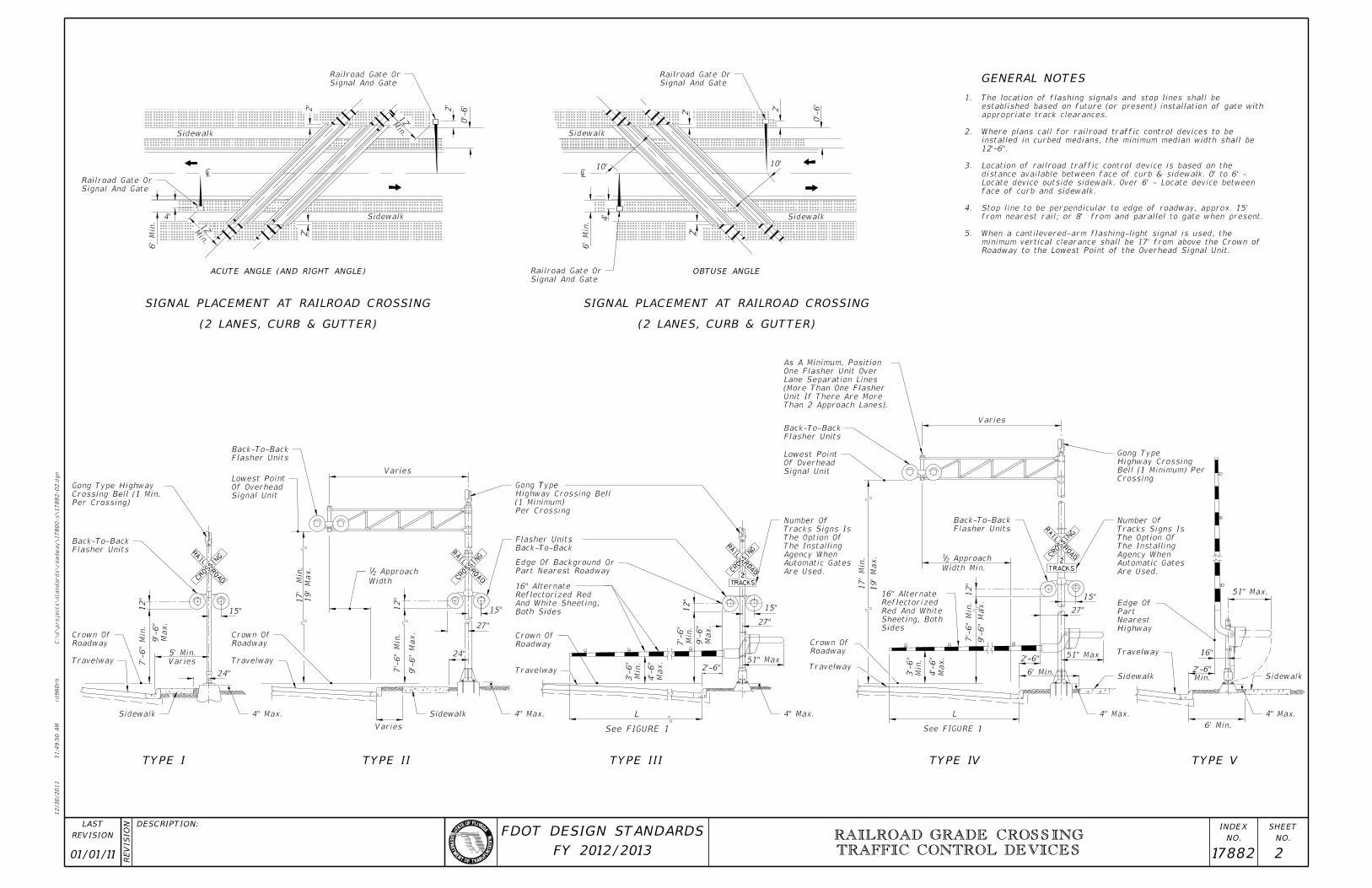
GENERAL NOTES
01/01/11 17882 2
RAILROAD GRADE CROSSING
TRAFFIC CONTROL DEVICES
12/30/2011
11:4
9:5
0
AM
RE
VISIO
N
C:\
d\projects\standards\road
way\17800-s\17882-02.d
gn
NO.
SHEET
NO.
INDEX
rd960rh
DESCRIPTION:
REVISION
LAST
FY 2012/2013
FDOT DESIGN STANDARDS
4" Max.
Sidewalk
Travelway
Highway
Nearest
Part
Edge Of
Are Used.
Automatic Gates
Agency When
The Installing
The Option Of
Tracks Signs Is
Number Of
Crossing
Bell (1 Minimum) Per
Highway Crossing
Gong Type
Sidewalk
4" Max.4" Max.4" Max.4" Max.Sidewalk Sidewalk
Are Used.
Automatic Gates
Agency When
The Installing
The Option Of
Tracks Signs Is
Number Of
Than 2 Approach Lanes).
Unit If There Are More
(More Than One Flasher
Lane Separation Lines
One Flasher Unit Over
As A Minimum, Position
Flasher Units
Back-To-Back
Signal Unit
Of Overhead
Lowest Point
Sides
Sheeting, Both
Red And White
Reflectorized
16" Alternate
Flasher Units
Back-To-Back
Per Crossing
(1 Minimum)
Highway Crossing Bell
Gong Type
Back-To-Back
Flasher Units
Part Nearest Roadway
Edge Of Background Or
Both Sides
And White Sheeting,
Reflectorized Red
16" Alternate
Roadway
Crown Of
Travelway
Width
Approach 21
Signal Unit
Of Overhead
Lowest Point
Flasher Units
Back-To-Back
Travelway
Roadway
Crown Of
Per Crossing)
Crossing Bell (1 Min.
Gong Type Highway
Flasher Units
Back-To-Back
Travelway
Roadway
Crown Of
Signal And Gate
Railroad Gate Or
Signal And Gate
Railroad Gate Or
Signal And Gate
Railroad Gate Or
Signal And Gate
Railroad Gate Or
CR
OSSI
NG
RAIL
RO
AD
6’ Min.
51" Max.
Varies
27"
24"
15"
Varies
19’
Max.
17’
Min.
Max.
9’-
6"
7’-
6"
Min.
Varies
5’ Min.
15"
6’
Min.
4’
¡
2’
Sidewalk
2’
2’
0’-
6’
10’
2’
0’-
6’
Sidewalk
10’
¡
Sidewalk
6’
Min.
4’
2’
2’
(2 LANES, CURB & GUTTER)
SIGNAL PLACEMENT AT RAILROAD CROSSING
(2 LANES, CURB & GUTTER)
SIGNAL PLACEMENT AT RAILROAD CROSSING
ACUTE ANGLE (AND RIGHT ANGLE) OBTUSE ANGLE
9’-
6"
Max.
7’-
6"
Min.
12"
51" Max
2’-6"
See FIGURE 1
L
15"
27"
Min.
3’-
6"
Max.
4’-
6"
Max.
9’-
6"
Min.
7’-
6"
12"
17’
Min.
19’
Max.
See FIGURE 1
L
12"
2’-6"
6’ Min.
Width Min.
Approach21
51" Max
27"
15"
7’-
6"
Min.
9’-
6"
Max.
Min.
3’-
6"
Max.
4’-
6"
Travelway
Roadway
Crown Of
Varies
16"
Min.
12’
Min.
12’
TYPE VTYPE IVTYPE IIITYPE IITYPE I
12"
Min.
2’-6"24"
Roadway to the Lowest Point of the Overhead Signal Unit.
minimum vertical clearance shall be 17’ from above the Crown of
When a cantilevered-arm flashing-light signal is used, the 5.
from nearest rail; or 8’ from and parallel to gate when present.
Stop line to be perpendicular to edge of roadway, approx. 15’ 4.
face of curb and sidewalk.
Locate device outside sidewalk. Over 6’ - Locate device between
distance available between face of curb & sidewalk. 0’ to 6’ -
Location of railroad traffic control device is based on the 3.
12’-6".
installed in curbed medians, the minimum median width shall be
Where plans call for railroad traffic control devices to be 2.
appropriate track clearances.
established based on future (or present) installation of gate with
The location of flashing signals and stop lines shall be 1.

DO NOT
STOP
ON
TRACKS
07/01/10 17882 3
RAILROAD GRADE CROSSING
TRAFFIC CONTROL DEVICES
12/30/2011
11:4
9:5
0
AM
RE
VISIO
N
C:\
d\projects\standards\road
way\17800-s\17882-03.d
gn
NO.
SHEET
NO.
INDEX
rd960rh
DESCRIPTION:
REVISION
LAST
FY 2012/2013
FDOT DESIGN STANDARDS
4"
16"
White
Message
Pavement
With Gates
Flashing Signal
Gate Or
(If Not with Gate)
Flashing Signal
As Required
Travel way
Edge Of
Stop Line
Line.
Of The RR Center
Located Within 12’
Device Is Not To Be
Railroad Protection
24" White
See Note 5
6" Dbl Yellow
24" White
Gate When Present.
Or 8’ From & Parallel To
to Edge Of Travel Way
Stop Bar Perpendicular
See Note 5
24" White
6" Dbl Yellow
24" White24" White
W10-1
W10-1
24" White
24" White
Location
Gate
Future
6" Dbl. Yellow
24" White
Gate When Present.
Or 8’ From & Parallel To
to Edge Of Travel Way
Stop Bar Perpendicular
Location
Future Gate
R R
85 MIN.
100
125
175
250
325
40060
55
50
45
40
35
URBAN
TWO (2)-LANE ROADWAY
RAILROAD CROSSING AT
MULTILANE ROADWAYRAILROAD CROSSING AT
CONTROL DEVICES
RELATIVE LOCATION OF CROSSING TRAFFIC
Intersections
Signalized
For Use Near
R8 - 8
20’
6’
20’
50’
20’
A
20’
6’
20’
50’
20’
A
10’
Min.
12’
8’
12’
4’
8’10’
Min.
12’
12’
10’
12’
8’
8’
10’12’
4’
8’
6’
6’-
0"
20’
¡
Of Lane
8’-0"
12"
6’
NOTES:
R R
of 4’.
from the gate tip to the inside edge of pavement is a maximum
The gate shall be of sufficient length such that the distance
For one-way or divided sections:
from the gate to the center line shall be a maximum of 4’.
within 1’ of the center line. For those cases, the distance
multiple approaches the maximum gate length may not reach to
The gate should extend to within 1’ of the center line. On
For Two-way undivided sections:
Gate Length Requirements:5.
urban and 300’ rural. See Index 17355 for sign details.
Recommended location for FTP-61-06 or FTP-62-06 signs, 100’ 4.
opposite the W10-1 sign.
A portion of the pavement markings symbol should be directly 3.
message should be used.
tracks an additional W10-1 sign and additional pavement
intersections occur between the RR pavement message and the
a minimum distance of 100’ from the crossing. Where street
where low speeds are prevalent, the W10-1 sign may be placed
Placement of sign W10-1 in a residential or business district, 2.
traverse lines.
When computing pavement message, quantities do not include 1.
(mph)
SPEED
(ft)
" A "
RO
ADC
ROSSI
NG
RAIL
01/01/12 17882 4
RAILROAD GRADE CROSSING
TRAFFIC CONTROL DEVICES
12/30/2011
11:4
9:5
2
AM
RE
VISIO
N
C:\
d\projects\standards\road
way\17800-s\17882-04.d
gn
NO.
SHEET
NO.
INDEX
rd960rh
DESCRIPTION:
REVISION
LAST
FY 2012/2013
FDOT DESIGN STANDARDS
White
Red
Red Flashing LightsRed Steady Burn
Crown Of RoadwayTravel Way
6" Min. Height
Type F Curb
18"18"
Sid
ewalk
Min)
(2’-6"
Varies
(Std.)
27"
Max.
51"
50’
Min.1
2’
Min.
12’-5" Min.
1’
1’
Sid
ewalk
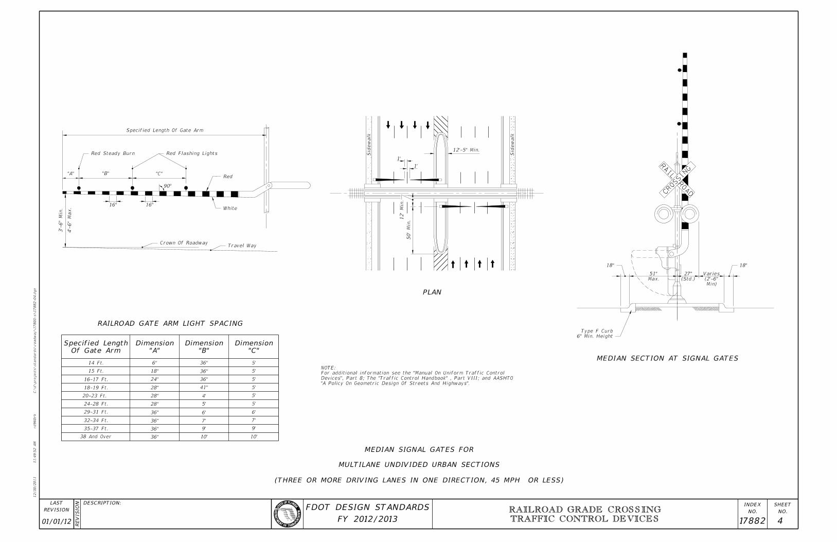
Specified Length Of Gate Arm
4’-
6"
Max.
3’-
6"
Min.
16" 16"
90°
"C""B""A"
5’
5’
5’
5’
5’
5’
6’
7’
9’
10’10’
9’
7’
6’
5’
4’
41"
36"
36"
36"6"
18"
24"
28"
28"
28"
36"
36"
36"
36"38 And Over
35-37 Ft.
32-34 Ft.
29-31 Ft.
24-28 Ft.
20-23 Ft.
18-19 Ft.
16-17 Ft.
15 Ft.
14 Ft.
"C"
Dimension
"B"
Dimension
"A"
Dimension
Of Gate Arm
Specified Length
RAILROAD GATE ARM LIGHT SPACING
PLAN
MEDIAN SECTION AT SIGNAL GATES
(THREE OR MORE DRIVING LANES IN ONE DIRECTION, 45 MPH OR LESS)
MULTILANE UNDIVIDED URBAN SECTIONS
MEDIAN SIGNAL GATES FOR
"A Policy On Geometric Design Of Streets And Highways".
Devices", Part 8; The "Traffic Control Handbook" , Part VIII; and AASHTO
For additional information see the "Manual On Uniform Traffic Control
NOTE: