rainwater solutions - lysaght.com · rainaer solions 2 the most common means to satisfy these...
TRANSCRIPT

RAINWATER SOLUTIONSQUEENSLAND

RA
INW
ATER
SOLU
TION
S2
The most common means to satisfy these requirements for roof drainage (i.e. guttering) installations is via compliance with the National Plumbing and Drainage Code AS/NZS 3500.3: 2015.
Furthermore, in each state and territory it is necessary to satisfy the relevant regulation.
In the design and detailing of a roof drainage system consideration must be given to a range of the factors such as rainfall intensity, roof catchment area, gutter size/capacity, gutter fall, gutter outlets (sumps, rainheads, nozzles), downpipe size, quantity and placement, overflow consideration, material selection, jointing, etc.
It is the responsibility of designers and installers of roof drainage systems to ensure compliance with these requirements.
IMPORTANT INFORMATION ON OVERFLOW MEASURES
For residential roof drainage systems, high fronted gutters are a popular aesthetic choice to hide the lower edge of tiles or roof cladding. Where high-fronted gutters are installed, the NCC (and AS/NZS 3500.3) requires that provision must be made to avoid any overflow back into the roof or building structure.
Some simple overflow control methods that can be employed on high fronted gutters are listed below. It is important to note that it may be necessary to use more than one of these measures to achieve the necessary result:
A) Methods related to the design and installation of roof drainage systems:
• Slotted front of gutter – simple and popular choice which allows for water overflow through the slots visible on the front face of the gutter;
• Specifically located non-continuous overflows as permitted in the NCC i.e.:
- Inverted downpipe drop/pop at high points in the gutter but set at a level below the fascia top,
- Stop ends cut down to a lower level to act as a weir (stop end weirs could be hidden at the high point of the gutter and designed as part of an expansion joint),
- Rainheads with overflow weir,
- Holes, slot, or weir at downpipes;
- Gap between the fascia and the gutter back – a packer is inserted between the gutter back and the fascia; or
Any of a number of other proprietary systems and trade solutions.
B) Methods related to alternative building designs methods:
• Unlined eaves – eliminates the issue where the house design suits.
• Gutter installed such that the gutter front is fully and sufficiently below the top of the fascia (freeboarding).
• Design for a higher rainfall intensity, as used for internal box gutters.
• Back flashing – where gutter support brackets allow back flashing installation (e.g. external brackets).
The following illustrations show some typical continuous and non-continuous overflow measures that may be used in combination with each other or with other overflow measures to meet the necessary requirements.
Please note that non-continuous measures may become blocked anywhere along their length, so non-continuous overflow measures may not be sufficient to prevent water from flowing back into a building.
Slotted gutters may also provide an overflow measure, however slots must be of sufficient size. For this reason, slots alone may not be a sufficient overflow measure in all circumstances. When designing a roof drainage system with slotted gutter, consideration should be given to additional overflow measures.
RAINWATER SOLUTIONS
Under the Environmental Planning and Assessment Act 1979 and its Regulations, all building work must be carried out in accordance with the National Construction Code (NCC). In addition to referring to Australian Standards AS/NZS 3500.3 (2015), and AS/NZS 3500.5 (2012), the NCC also contains requirements for the disposal of surface water in Volume One, in Performance Requirements FP1.2 and FP1.3, and in Volume Two, in Part 3.5.2, namely, Performance Requirements P2.2.1 and Clauses 3.5.2.1 and 3.5.2.4.
Water overflow in domestic rainwater systems
Typical overflow from slotted gutter.
(Gutter shown is not available in all areas).

RA
INW
ATE
R S
OLU
TIO
NS
3
DESIGN AND INSTALLATION OF DOMESTIC ROOF DRAINAGE SYSTEMS
The detailing and sizing of the selected overflow method/s is normally completed by the designer/installer, but must be adequate for the situation and must meet the relevant performance requirements of the NCC and Australian Standards, including the requirements noted above.
While there may be some variations from state to state, contractors who install guttering systems are generally required to hold an appropriate licence. The work is required to comply with the appropriate codes and standards.
Statutory warranties normally apply and consumers have a right to lodge a complaint and have it dealt with by the appropriate authority.
In the installation of the roof drainage system, particular focus should be given to the following;
• Attention to the use of compatible materials for drainage system components, leaf-guard type system components and compatible fasteners/sealants to connect and seal the components.
• The position of the gutter in relation to the fascia (particularly, whether there is a gap between the fascia and the gutter back and whether the gutter front is below the top of the fascia).
• Installation of the specified gutter and downpipes, ensuring that downpipes are installed in the correct locations and numbers.
• Gutter fall, ensuring sufficient fall and that it is in the direction of the downpipes.
• Overflow has been considered and specific details are installed where required as described above (such as when the gutter front is higher than the top of the fascia).
During the installation all debris and loose waste materials (swarf, fasteners, etc.) must be cleaned off at the end of each day and at the completion of the installation to prevent blockages of the drainage system or deterioration of the individual components. Any protective films should also be removed as part of the installation process.
MAINTENANCE OF DOMESTIC ROOF DRAINAGE SYSTEMS
In the longer term, the ability of a roof drainage system to handle overflow will also depend on the regular cleaning of the system. For example the removal of plant or animal matter (leaves, fungal growth, dropping, nests, etc.) and debris from gutters, leaf-guard type systems and the gutter overflow devices to ensure free drainage of water.
To ensure the long life of the roof drainage system, the maintenance requirements of the roof drainage system should be forwarded to the occupier/owner of the building and should be fulfilled. Adequate maintenance is a requirement of rainwater goods warranties.
Continuous (full length) overflow measures
Gutter
Fascia
Front of gutter below top of fascia
Gutter
Gap between gutter and fascia
Non-continuous (specifically located) overflow measures
Gutter
Downpipe nozzle
Fascia
Inverted nozzle at high ends of gutterfinished below back of gutter
Stop ends finished below the top of the fascia and rear of the gutter to form a weir
Gutter
RA
INW
ATER
SOLU
TION
S4
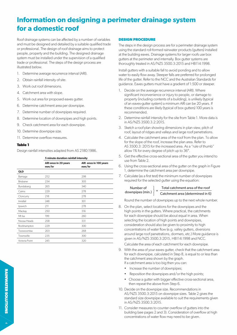
Information on designing a perimeter drainage system for a domestic roof
DESIGN PROCEDURE
The steps in the design process are for a perimeter drainage system using the standard roll-formed rainwater products (gutters) installed at the building eaves. Drainage systems for larger roofs use box gutters at the perimeter and internally. Box gutter systems are thoroughly treated in AS/NZS 3500.3:2015 and HB114:1998.
Install gutters with a suitable fall to avoid ponding and to allow water to easily flow away. Steeper falls are preferred for prolonged life of the gutter. Refer to the NCC and the Australian Standards for guidance. Eaves gutters must have a gradient of 1:500 or steeper.
1. Decide on the average recurrence interval (ARI). Where significant inconvenience or injury to people, or damage to property (including contents of a building), is unlikely (typical of an eaves-gutter system) a minimum ARI can be 20 years. If these conditions are likely (typical of box gutters) 100 years is recommended.
2. Determine rainfall intensity for the site from Table 1. More data is in AS/NZS 3500.3.2:2015.
3. Sketch a roof plan showing dimensions in plan view, pitch of roof, layout of ridges and valleys and large roof penetrations.
4. Calculate the catchment area of the roof from the plan. To allow for the slope of the roof, increase the plan area. Refer to AS 3500.3: 2015 for the increased area. As a “rule of thumb” allow 1% for every degree of pitch up to 36°.
5. Get the effective cross-sectional area of the gutter you intend to use from Table 2.
6. Using the cross-sectional area of the gutter on the graph in Figure 1, determine the catchment area per downpipe.
7. Calculate (as a first test) the minimum number of downpipes required for the selected gutter using the equation:
Round the number of downpipes up to the next whole number.
8. On the plan, select locations for the downpipes and the high points in the gutters. Where practical, the catchments for each downpipe should be about equal in area. When selecting the location of high points and downpipes, consideration should also be given to proximity to high concentrations of water flow (e.g. valley gutters, diversions around large roof penetrations, dormers, etc.) More guidance is given in AS/NZS 3500.3:2015, HB114:1998 and NCC.
Calculate the area of each catchment for each downpipe.9. With the area of your eaves gutter, check that the catchment area
for each downpipe, calculated in Step 8, is equal to or less than the catchment area shown by the graph. If a catchment area is too big then you can:• Increase the number of downpipes;• Reposition the downpipes and/or the high points;• Choose a gutter with bigger effective cross-sectional area,
then repeat the above from Step 6.10. Decide on the downpipe size. Recommendations in
AS/NZS 3500.3:2015 on downpipe sizes. Table 2 gives the standard size downpipe available to suit the requirements given in AS/NZS 3500.3:2015.
11. Consider measures to counter overflow of gutters into the building (see pages 2 and 3). Consideration of overflow at high concentrations of water flow may need to be given.
Roof drainage systems can be affected by a number of variables and must be designed and detailed by a suitable qualified trade or professional. The design of roof drainage aims to protect people, property and the building. The designed drainage system must be installed under the supervision of a qualified trade or professional. The steps of the design process are illustrated below.
1. Determine average recurrence interval (ARI).
2. Obtain rainfall intensity of site.
3. Work out roof dimensions.
4. Catchment area with slope.
5. Work out area for proposed eaves gutter.
6. Determine catchment area per downpipe.
7. Determine number of downpipes required.
8. Determine location of downpipes and high points.
9. Check catchment area for each downpipe.
10. Determine downpipe size.
11. Determine overflow measures.
Table 1
Design rainfall intensities adapted from AS 2180:1986.
5 minute duration rainfall intensity
ARI once in 20 years mm/hr
ARI once in 100 years mm/hr
QLD
Bamaga 252 298
Brisbane 234 305
Bundaberg 265 340
Cairns 229 278
Cloncurry 218 278
Innisfail 248 301
Ipswich 211 278
Mackay 250 316
Mt Isa 199 260
Noosa Heads 258 331
Rockhampton 229 300
Toowoomba 203 268
Townsville 235 300
Victoria Point 245 320
Number ofdownpipes (min.)
Total catchment area of the roof
Catchment area (determined in 6)=

RA
INW
ATE
R S
OLU
TIO
NS
5
Table 2
LYSAGHT® gutter areas and downpipes.
Minimum standard downpipe sizes to suit gutters (gutter fall ≥ 1:500)
Slotted Effective # cross section
Round (diameter)
Rectangular or square
yes/no mm2 mm mm
Quad 115 yes 5225 90 100x50
no 5809 90 100x50
Quad 150 no 8631 125 ▲ 100x75
Quad Hi-front 150 yes 6700 100 100x75
no 7430 100 100x75
Quad 175 no 14,500 150 ▲ 125x100 ▲
TRIMLINE® yes 6244 90 100x50
no 7800 100 100x75
EMLINE® yes 6273 100 100x75
no 9536 125 ▲ 100x75
FITFAST® yes 6723 100 100x75
no 7209 100 100x75
Half Round Flat Back 150 yes 5580 90* 100x50*
no 9170 ▲ 100x75*
Half Round 150 yes 5730 90* 100x50*
no 9440 ▲ 100x75*
Half Round Flat Back 190 yes - - -
no 10750 ▲ 100x100*
Half Round 190 yes - - -
no 10475 ▲ 100x100*
# Values calculated in accordance with AS/NZS 3500.3:2015. ▲ Non standard downpipe and nozzle/pop is required. * Non standard nozzle/pop is required to suit downpipe.
EXAMPLEFind the minimum catchment area for each downpipe on a house in Mt Isa using Quad Hi-front gutter.
MethodUsing the gutter cross sectional area taken from Table 2 (shown across the bottom of the graph) draw a line upwards until it intersects with the Design rainfall intensity (Table 1). Draw a line at 90˚ to determine the catchment area for each downpipe.
DATADesign rainfall intensity = 169 (Table 1)Gutter area = 5809 (Table 2)
SOLUTION (From Figure 1)Catchment area for each downpipe = 34m2
Effective cross-sectional area of eaves gutter (mm2)(Gradient 1:500 and steeper).
Cat
chm
ent a
rea
for e
ach
vert
ical
dow
npip
e (m
2)
03000 4000 5000 6000 7000 8000 9000 10000 11000 12000
10
20
30
40
50
50
60
70
80
90
100
100
150
200
300
400
500
Design rainfall intensities (mm/h)
Effective cross-sectional area of eaves gutter (mm2)(Gradient 1:500 and steeper).
Cat
chm
ent a
rea
for e
ach
vert
ical
dow
npip
e (m
2)
03000 4000 5000 6000 7000 8000 9000 10000 11000 12000
10
20
30
40
50
50
60
70
80
90
100
100
150
200
300
400
500
Design rainfall intensities (mm/h)
Figure 1
Cross-sectional area of eaves gutters required for various roof catchment areas (where gradient of gutter is 1:500 and steeper). (Adapted from AS 3500.3:2015).
Table 3
NCC Gutter Type.
Gutter Type
Description Min. Cross Section (mm2)
Suitable Gutter Selection
A Rectangular (Medium)
6500 TRIMLINE®, no slots
EMLINE®, no slots
EMLINE®, slotted
FITFAST®, no slots
FITFAST®, slotted
B Rectangular (Large)
7900 EMLINE®, no slots
C D gutter (Small)
5200 Quad 115, no slots
Quad 115, slotted
Quad Hi-front 150, no slots
Quad Hi-front 150, slotted
Quad 150, no slots
D D gutter (Medium)
6300 Quad Hi-front 150, no slots
Quad Hi-front 150, slotted
Quad 150, no slots
E D gutter (Large) 9000 Quad 175, no slots
Where the roof drainage system is designed and constructed in accordance with the Acceptable Construction Practice given in the NCC the above tables lists the gutters that can be used for the different Gutter Types (as described in the NCC Volume Two 2016, Table 3.5.2.2b).
RA
INW
ATER
SOLU
TION
S6
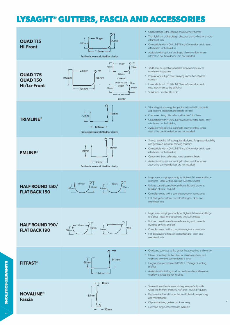
LYSAGHT® GUTTERS, FASCIA AND ACCESSORIES
• Quick and easy way to fit a gutter that saves time and money
• Clever mounting bracket ideal for situations where roof overhang prevents connection to a fascia
• Elegant style complements LYSAGHT® range of roofing profiles
• Available with slotting to allow overflow where alternative overflow devices are not installed
QUAD 175 QUAD 150 Hi/Lo-Front
QUAD 115 Hi-Front
TRIMLINE®
HALF ROUND 150/ FLAT BACK 150
HALF ROUND 190/FLAT BACK 190
EMLINE®
150mm
95mm85mm
138mm
95mm85mm
195mm
90mm110mm
180mm
90mm110mm
FITFAST®
• Strong, attractive ‘M’ style gutter designed for greater durability and generous rainwater carrying capacity
• Compatible with NOVALINE® Fascia System for quick, easy attachment to the building
• Concealed fixing offers clean and seamless finish
• Available with optional slotting to allow overflow where alternative overflow devices are not installed
• Slim, elegant square gutter particularly suited to domestic applications that is fast and simple to install
• Concealed fixing offers clean, attractive ‘trim’ lines
• Compatible with NOVALINE® Fascia System for quick, easy attachment to the building
• Available with optional slotting to allow overflow where alternative overflow devices are not installed
• Large water carrying capacity for high rainfall areas and large roof sizes - ideal for tropical/sub-tropical climates
• Unique curved base allows self-cleaning and prevents build-up of water and dirt
• Complemented with a complete range of accessories
• Flat Back gutter offers concealed fixing for clean and seamless finish
103mm
164mm
95mm
Zinger150mm
74mm78mm
Zinger
LO-FRONT
150mm
90mm62mmZinger
Overflow Slot
HI-FRONT
68mm141mm
124mm
89mm140mm
125mm
Profile shown unslotted for clarity.
72mm116mm
124mm
Profile shown unslotted for clarity.
62mm
115mm
90mmZinger
Profile shown unslotted for clarity.
18mm
35mm
185mm
• Traditional design that is suitable for new homes or to match existing gutters
• Popular where high water carrying capacity is of prime concern
• Compatible with NOVALINE® Fascia System for quick, easy attachment to the building
• Suitable for steel or tile roofs
• State-of-the-art fascia system integrates perfectly with Quad 115 Hi-front and EMLINE® and TRIMLINE® gutters
• Replaces traditional timber fascia which reduces painting and maintenance
• Clips make fixing gutters quick and easy
• Extensive range of accessories available
• Classic design is the leading choice of new homes
• The high front profile design obscures the roofline for a more attractive finish
• Compatible with NOVALINE® Fascia System for quick, easy attachment to the building
• Available with optional slotting to allow overflow where alternative overflow devices are not installed
NOVALINE®
Fascia
RA
INW
ATE
R S
OLU
TIO
NS
7
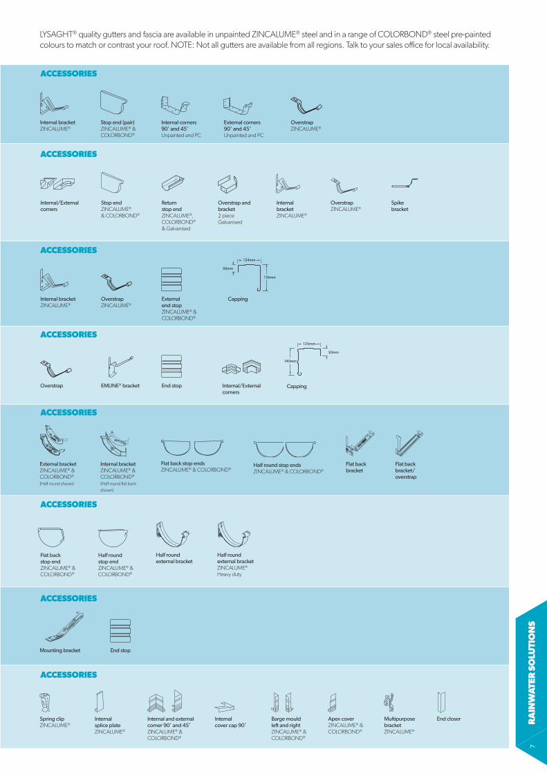
LYSAGHT® quality gutters and fascia are available in unpainted ZINCALUME® steel and in a range of COLORBOND® steel pre-painted colours to match or contrast your roof. NOTE: Not all gutters are available from all regions. Talk to your sales office for local availability.
ACCESSORIES
Internal bracketZINCALUME®
Internal corners 90˚ and 45˚Unpainted and PC
OverstrapZINCALUME®
Stop end (pair)ZINCALUME® & COLORBOND®
External corners 90˚ and 45˚Unpainted and PC
Internal bracketZINCALUME®
Stop endZINCALUME® & COLORBOND®
Return stop endZINCALUME®, COLORBOND® & Galvanised
Overstrap and bracket2 pieceGalvanised
ACCESSORIES
Internal/External corners
OverstrapZINCALUME®
Spike bracket
ACCESSORIES
Internal bracketZINCALUME®
OverstrapZINCALUME®
External end stopZINCALUME® & COLORBOND®
Capping
116mm
30mm
124mm
ACCESSORIES
External bracketZINCALUME® & COLORBOND®
(Half round shown)
Flat back stop endsZINCALUME® & COLORBOND®
Half round stop ends ZINCALUME® & COLORBOND®
Internal bracketZINCALUME® & COLORBOND®
(Half round flat back shown)
Flat back bracket
Flat back bracket/overstrap
ACCESSORIES
Flat back stop endZINCALUME® & COLORBOND®
Half round stop end ZINCALUME® & COLORBOND®
Half round external bracket
Half round external bracketZINCALUME®
Heavy duty
ACCESSORIES
Mounting bracket End stop
ACCESSORIES
Apex coverZINCALUME® & COLORBOND®
Barge mould left and rightZINCALUME® & COLORBOND®
Internal and external corner 90˚ and 45˚ZINCALUME® & COLORBOND®
Internal cover cap 90˚
Internal splice plateZINCALUME®
Spring clipZINCALUME®
Multipurpose bracketZINCALUME®
End closer
ACCESSORIES
Overstrap EMLINE® bracket End stop
140mm
30mm
125mm
CappingInternal/External corners
RA
INW
ATER
SOLU
TION
S8
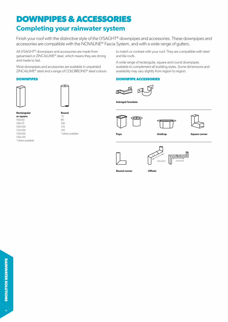
DOWNPIPES & ACCESSORIES
Finish your roof with the distinctive style of the LYSAGHT® downpipes and accessories. These downpipes and accessories are compatible with the NOVALINE® Fascia System, and with a wide range of gutters.
Completing your rainwater system
All LYSAGHT® downpipes and accessories are made from galvanised or ZINCALUME® steel, which means they are strong and made to last.
Most downpipes and accessories are available in unpainted ZINCALUME® steel and a range of COLORBOND® steel colours
to match or contrast with your roof. They are compatible with steel and tile roofs.
A wide range of rectangular, square and round downpipes available to complement all building styles. Some dimensions and availability may vary slightly from region to region.
Astragal/brackets
Offsets
AdjustableAdjustable
Pops Unidrop Square corner
Round corner
DOWNPIPE ACCESSORIES
Rectangular or square100x50100x75100x100125x100150x100150x150*others available
Round7590100125150*others available
DOWNPIPES
RA
INW
ATE
R S
OLU
TIO
NS
9
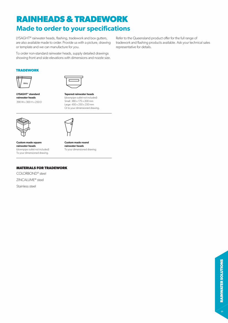
LYSAGHT® rainwater heads, flashing, tradework and box gutters, are also available made to order. Provide us with a picture, drawing or template and we can manufacture for you.
To order non-standard rainwater heads, supply detailed drawings showing front and side elevations with dimensions and nozzle size.
Refer to the Queensland product offer for the full range of tradework and flashing products available. Ask your technical sales representative for details.
RAINHEADS & TRADEWORKMade to order to your specifications
MATERIALS FOR TRADEWORK
COLORBOND® steel
ZINCALUME® steel
Stainless steel
Custom made square rainwater heads (downpipe outlet not included)To your dimensioned drawing.
Custom made round rainwater headsTo your dimensioned drawing.
LYSAGHT® standard rainwater heads
390 W x 300 H x 250 D
Tapered rainwater heads(downpipe outlet not included)Small: 380 x 175 x 200 mmLarge: 450 x 250 x 250 mmOr to your dimensioned drawing.
TRADEWORK
RA
INW
ATER
SOLU
TION
S10
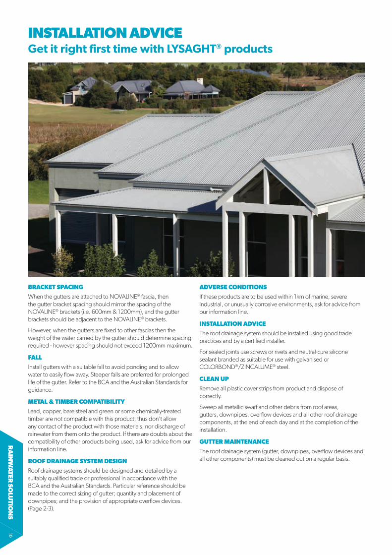
INSTALLATION ADVICEGet it right first time with LYSAGHT® products
BRACKET SPACING
When the gutters are attached to NOVALINE® fascia, then the gutter bracket spacing should mirror the spacing of the NOVALINE® brackets (i.e. 600mm & 1200mm), and the gutter brackets should be adjacent to the NOVALINE® brackets.
However, when the gutters are fixed to other fascias then the weight of the water carried by the gutter should determine spacing required - however spacing should not exceed 1200mm maximum.
FALL
Install gutters with a suitable fall to avoid ponding and to allow water to easily flow away. Steeper falls are preferred for prolonged life of the gutter. Refer to the BCA and the Australian Standards for guidance.
METAL & TIMBER COMPATIBILITY
Lead, copper, bare steel and green or some chemically-treated timber are not compatible with this product; thus don’t allow any contact of the product with those materials, nor discharge of rainwater from them onto the product. If there are doubts about the compatibility of other products being used, ask for advice from our information line.
ROOF DRAINAGE SYSTEM DESIGN
Roof drainage systems should be designed and detailed by a suitably qualified trade or professional in accordance with the BCA and the Australian Standards. Particular reference should be made to the correct sizing of gutter; quantity and placement of downpipes; and the provision of appropriate overflow devices. (Page 2-3).
ADVERSE CONDITIONS
If these products are to be used within 1km of marine, severe industrial, or unusually corrosive environments, ask for advice from our information line.
INSTALLATION ADVICE
The roof drainage system should be installed using good trade practices and by a certified installer.
For sealed joints use screws or rivets and neutral-cure silicone sealant branded as suitable for use with galvanised or COLORBOND®/ZINCALUME® steel.
CLEAN UP
Remove all plastic cover strips from product and dispose of correctly.
Sweep all metallic swarf and other debris from roof areas, gutters, downpipes, overflow devices and all other roof drainage components, at the end of each day and at the completion of the installation.
GUTTER MAINTENANCE
The roof drainage system (gutter, downpipes, overflow devices and all other components) must be cleaned out on a regular basis.

RA
INW
ATE
R S
OLU
TIO
NS
11
GUTTER MAINTENANCEGetting the most from LYSAGHT®products
CLEANING GUTTERS
Twigs, dust, leaves and fungal matter (debris) should be removed regularly from gutters - as failure to do so voids your warranty.
• Sweep debris into a pile using a stiff, soft bristled brush (shovels or hard tools should not be used).
• The whole roof and gutter should then be washed down with a hose, including high ends of gutters (possibly protected by overhangs), rain heads, water spouts and overflow locations.
A well maintained gutter/downpipe will make your rainwater system provide years and years of trouble-free service.
3) When litter is removed, the layer of hardened dirt is revealed below.
6) When the gutter has been cleaned, it should look like this.
1) A typical suburban gutter clogged with leaf litter prior to cleaning.
4) Rinse the gutter with water to soften and break up the dirt.
2) Wear correct protection when clearing leaves and twigs.
5) Use a soft bristle brush and sweep the dirt out. Rinse again.

WWW.LYSAGHT.COM
Technical enquiries: [email protected] or call 1800 641 417
LYSAGHT®, NOVALINE®, TRIMLINE®, EMLINE®, COLORBOND® & ZINCALUME® are registered trademarks of BlueScope Steel Limited, ABN 16 000 011 058. The LYSAGHT® range of products is exclusively made by or for BlueScope Steel Limited trading as Lysaght.
PRODUCT DESCRIPTIONS
• All descriptions, specifications, illustrations, drawings, data, dimensions and weights contained in this catalogue, all technical literature and websites containing information from Lysaght are approximations only. They are intended by Lysaght to be a general description for information and identification purposes and do not create a sale by description. Lysaght reserves the right at any time to: (a) supply Goods with such minor modifications from its drawings and specifications as it sees fit; and (b) alter specifications shown in its promotional literature to reflect changes made after the date of such publication.
DISCLAIMER, WARRANTIES AND LIMITATION OF LIABILITY
• This publication is intended to be an aid for all trades and professionals involved with specifying and installing Lysaght products and not to be a substitute for professional judgement.
• Terms and conditions of sale available at local Lysaght sales offices.
• Except to the extent to which liability may not lawfully be excluded or limited, BlueScope Steel Limited will not be under or incur any liability to you for any direct or indirect loss or damage (including, without limitation, consequential loss or damage such as loss of profit or anticipated profit, loss of use, damage to goodwill and loss due to delay) however caused (including, without limitation, breach of contract, negligence and/or breach of statute), which you may suffer or incur in connection with this publication.
© Copyright BlueScope Steel Limited 26 August 2016
LYT0
034
26.0
8.16