rambo 1.1b user manual by reprap electro
TRANSCRIPT
P a g e | 1
RAMBo 1.1B User Manual
by RepRap Electro
RAMBo board designed by UltiMachine
P a g e | 2
USER MANUAL CHANGELOG
Date Author Version Changes
02/09/2014 Kakaroto 1.0 Initial release
CREDITS
Johnny Russell for the design of the RAMBo.
Thomas Sanladerer for providing us with images (the ones that look good) for the manual.
anethema (IRC) for reviewing and correcting the manual.
P a g e | 3
CONTENTS
Table of figures .............................................................................................................................................................. 4
Disclaimer ...................................................................................................................................................................... 7
Licensing information and Credits ................................................................................................................................. 8
Introduction ................................................................................................................................................................... 9
Software setup ............................................................................................................................................................ 10
Installing RAMBo drivers ......................................................................................................................................... 10
Arduino IDE setup ................................................................................................................................................... 13
Firmware setup - Marlin .......................................................................................................................................... 15
Hardware setup ........................................................................................................................................................... 19
Cable preparation .................................................................................................................................................... 20
Motors ................................................................................................................................................................ 20
Power input......................................................................................................................................................... 24
Mosfets (heaters, fans and heat-bed) ................................................................................................................ 27
Thermistors ......................................................................................................................................................... 29
Endstops.............................................................................................................................................................. 30
Connecting the RAMBo ........................................................................................................................................... 33
Power input......................................................................................................................................................... 34
Mosfets ............................................................................................................................................................... 35
Motors ................................................................................................................................................................ 35
Endstops.............................................................................................................................................................. 38
Thermistors ......................................................................................................................................................... 39
USB Cable ............................................................................................................................................................ 41
Smart LCD Controller .......................................................................................................................................... 42
Auxiliary Connectors ........................................................................................................................................... 45
Configuration and troubleshooting ............................................................................................................................. 55
Configuration of the digital potentiometer ............................................................................................................. 55
P a g e | 4
Setup of a servo motor for auto-bed leveling ......................................................................................................... 56
Configuration of Board power selector ................................................................................................................... 59
Replacing fuses ........................................................................................................................................................ 61
Appendix A - RAMBo 1.1B Schematic .......................................................................................................................... 63
Appendix B - RAMBo Arduino Mega 2560 pin mappings ............................................................................................ 64
Appendix C - GNU Free Documentation License ......................................................................................................... 67
Appendix D - Creative Commons Attribution-ShareAlike 3.0 Unported ..................................................................... 75
TABLE OF FIGURES
Figure 1 - Driver files .................................................................................................................................................... 11
Figure 2 - Driver Install contextual menu .................................................................................................................... 11
Figure 3 - Driver install Windows Security warning ..................................................................................................... 12
Figure 4 - Driver installation successful ....................................................................................................................... 12
Figure 5 - Atmega2560 board selection in Arduino IDE............................................................................................... 13
Figure 6 - Copy Arduino Addons rambo directory to Arduino/hardware directory .................................................... 14
Figure 7 - RAMBo board selection in Arduino IDE ....................................................................................................... 15
Figure 8 - Motherboard selection in Marlin ................................................................................................................ 16
Figure 9 - Upload button in toolbar ............................................................................................................................. 17
Figure 10 - Labeled accessories of RAMBo .................................................................................................................. 19
Figure 11 - Motor wire connectors - RAMBo Compatible, non-compatible, and RAMBo connector.......................... 20
Figure 12 - Crimp pins .................................................................................................................................................. 21
Figure 13 - Crimp pin details ........................................................................................................................................ 21
Figure 14 - Stripped wire positioned on crimp pin ...................................................................................................... 22
Figure 15 - Result of crimped wire with needle-nose pliers ........................................................................................ 23
Figure 16 - Crimp pin with connector housing ............................................................................................................ 23

P a g e | 5
Figure 17 - Connector housing with all crimp pins inserted in the correct order ........................................................ 24
Figure 18 - 6-pin pluggable green connector ............................................................................................................... 24
Figure 19 - Lowered metal plate for wire insertion ..................................................................................................... 25
Figure 20 - Wire inserted in the appropriate gap of connector before tightening of the screw ................................. 25
Figure 21 - Labeled power connector with polarities .................................................................................................. 26
Figure 22 - Inserted power connector with polarities ................................................................................................. 26
Figure 23 - Wired power supply .................................................................................................................................. 27
Figure 24 - 2-pin pluggable green connector ............................................................................................................... 27
Figure 25 - Connector with wires and polarity labels .................................................................................................. 28
Figure 26 - Inserted connector with board polarities .................................................................................................. 28
Figure 27 - Thermistor wire set ................................................................................................................................... 29
Figure 28 - Standard pre-wired thermistor.................................................................................................................. 29
Figure 29 - Endstop and wire harness ......................................................................................................................... 30
Figure 30 - Wired endstop - No inverting .................................................................................................................... 30
Figure 31 - Marlin endstop inverting options - False ................................................................................................... 31
Figure 32 - Wired endstop - Inverting .......................................................................................................................... 31
Figure 33 - Marlin endstop inverting options - True .................................................................................................... 32
Figure 34 - RAMBo main connectors ........................................................................................................................... 33
Figure 35 - Power input connector .............................................................................................................................. 34
Figure 36 - Power input connector with insert connectors ......................................................................................... 34
Figure 37 - Mosfets ...................................................................................................................................................... 35
Figure 38 - Inserted motor connector ......................................................................................................................... 36
Figure 39 - Motor connectors on the board ................................................................................................................ 36
Figure 40 - Invert motor direction in software ............................................................................................................ 37
Figure 41 - Endstop connectors on the board ............................................................................................................. 38
Figure 42 - Connected mechanical endstops to Z-Min, X-Max, Y-Max. Black=Ground, White=S ................................ 39
Figure 43 - Thermistor connectors on the board......................................................................................................... 39
P a g e | 6
Figure 44 - Thermistors connected to T0 and T1 connectors ...................................................................................... 40
Figure 45 - USB connector and Reset button .............................................................................................................. 41
Figure 46 - Smart LCD Adapter inserted on RAMBo .................................................................................................... 42
Figure 47 - EXP1 and EXP2 connectors on Smart LCD Controller ................................................................................ 42
Figure 48 - EXP1 and EXP2 connectors on Full Graphics Smart LCD Controller ........................................................... 43
Figure 49 - Labeled positions for EXP1 and EXP2 on Smart LCD Adapter .................................................................... 43
Figure 50 - Connected ribbon cable on Smart LCD Adapter ........................................................................................ 44
Figure 51 - Main and Auxiliary connectors .................................................................................................................. 45
Figure 52 - I2C, Serial, SD/SPI, Motor-Ext pins ............................................................................................................. 46
Figure 53 - PWM and EXT-2 pins ................................................................................................................................. 46
Figure 54 - Analog-Ext pins .......................................................................................................................................... 47
Figure 55 - Motor-Ext connector ................................................................................................................................. 48
Figure 56 - Motor Ext Schematic ................................................................................................................................. 48
Figure 57 - I2C Expansion schematic ........................................................................................................................... 49
Figure 58 - Serial Extension Schematic ........................................................................................................................ 50
Figure 59 - SPI Extension Schematic ............................................................................................................................ 51
Figure 60 - PWM Extension Schematic ........................................................................................................................ 52
Figure 61 - Extension 2 Schematic ............................................................................................................................... 53
Figure 62 - Analog Ext Schematic................................................................................................................................. 54
Figure 63 - Digital motor current variable in Marlin .................................................................................................... 55
Figure 64 - PWM and EXT-2 pins ................................................................................................................................. 57
Figure 65 - Adding Servo configuration to Marlin ....................................................................................................... 58
Figure 66 - PSEL Power Selection jumper : USB ........................................................................................................... 59
Figure 67 - PSEL Power Selection jumper : PSU ........................................................................................................... 60
Figure 68 - F2 and F3 LittleFuse 5A fuses..................................................................................................................... 61
Figure 69 - F4 ATO blade 15A fuse ............................................................................................................................... 62

P a g e | 7
DISCLAIMER
Handle with care. Static sensitive device.
Reversing input power polarity can damage electronics and cause fire hazard!
Test all electronics thoroughly before placing into service.
Do not leave power supplied to electronics unattended, or run machines unattended due to risk of fire or malfunc-
tion.
This is NOT a toy and it contains small and sharp parts. Children can choke or suffocate by swallowing small ob-
jects. Keep all parts away from children and never leave printer/parts unattended.

P a g e | 8
LICENSING INFORMATION AND CREDITS
The RAMBo was designed by Johnny Russell for UltiMachine. UltiMachine (Johnny, Britt, Dorothy, Lee, Bruce)
holds the Copyright and Intellectual Property of the design of the RAMBo. Based on work by the Arduino Team and
the RepRap project.
RAMBo is licensed under the Creative Commons Attribution-ShareAlike 3.0 Unported License so please use, copy,
improve, hack, upgrade, and / or contribute to the project.
This User Manual was written by Youness Alaoui for RepRap Electro with some images provided by Thomas
Sanladerer. The user manual is released under the GNU Free Documentation License v1.3. Permission is granted to
copy, distribute and/or modify this document.
Please see Annex C and Annex D for the full terms of these licenses.
Copyright (C) RepRap Electro
Permission is granted to copy, distribute and/or modify this document
under the terms of the GNU Free Documentation License, Version 1.3
or any later version published by the Free Software Foundation;
with no Invariant Sections, no Front-Cover Texts, and no Back-Cover Texts.
A copy of the license is included in the section entitled "Annex C - GNU
Free Documentation License".

P a g e | 9
INTRODUCTION
The RAMBo (RepRap Arduino-Mega Board) Controller Board for 3D printers is an all-in-one electronics board for all
your 3D printing needs. It is the successor of the popular RAMPS (RepRap Arduino-Mega Pololu Shield) shield used
to control most RepRap 3D printers.
Other than the all-in-one advantage, the RAMBo adds many improvements over the RAMPS by the addition of new
easy to use connectors for motors, endstops, thermistors, heaters and power connectors. These connectors will
insert easily and will clip into place and can be released by pressing the connector's side before removing them.
RAMBo has three separate connectors for power and it allows you to power the motors, mosfets and heat-bed
separately. It also has replaceable fuses that protect the board from over-current and allows you to replace them
without any soldering required. The design of the RAMBo also allows it to act as a heat dissipater for the stepper
motor drivers, which means that there is no need to install a heatsink on the stepper driver chips as was often the
case with the RAMPS.
The RAMBo supports an input power voltage of 12V or 24V, and it has 6 mosfets for controlling 2 heaters, one
heat-bed and up to 3 fans. It supports 6 motors with 5 integrated stepper drivers and digital potentiometer, one
connector each for the X axis, Y axis, first and second extruders and two duplicated connectors for the Z axis. It also
has connectors for up to 4 thermistors and 6 endstops. While the logic circuit of the board can be powered by
USB, a jumper can be set on the board to power the logic directly from the power supply, allowing for untethered
printing. Plenty of headers are available for expansion, allowing you to connect an SD card reader, Smart LCD dis-
plays, I2C device, extra motors, etc..
On top of all these improvements over other RepRap electronic boards, the RAMBo also includes a digital potenti-
ometer which can be used to calibrate your stepper motor's current. There is no more need to turning tiny knobs
on your steppers to calibrate the current to the motors, you can now set the current directly in your firmware. You
can also change the current dynamically by sending commands to your printer through Pronterface for example.
This will allow for fine-tuning of the current and minimize the motor noise, motor heat and the risk of missing
steps.
P a g e | 10
SOFTWARE SETUP
Before using the RAMBo, you must first upload a firmware to it. RAMBo boards come pre-loaded with a default
Marlin firmware, but you will almost certainly want to upload a firmware configured for your specific printer.
Since RAMBo is based on Arduino, we will use the Arduino IDE (Integrated Development Environment) to upload
the firmware to it. The Arduino IDE will require modifications to take advantage of the full capabilities of the
RAMBo, so we will copy some files to the Arduino installation directory to set it up for use with the RAMBo. This
step is however optional but it will help unlock the full potential of the board.
Once the Arduino IDE is correctly set up, we will upload to it a compatible firmware set-up for your 3D printer and
configured to use RAMBo.
INSTALLING RAMBO DRIVERS
If you are using Linux or Mac OS X, then you do not need to install drivers as they will use the USB CDC interface
which has hardware drivers built in the operating system.
If you are using a Windows Operating System, then you will need to install drivers for your RAMBo. When you first
connect the board to your computer, it will not be recognized by the system.
To install the driver, simply download it from the following URL : http://reprapelectro.com/wp-
content/uploads/2014/07/RAMBo-Driver.zip
Extract the contents of the RAMBo-Driver.zip file, you will find it contains two files, rambo.cat and rambo.inf :

P a g e | 11
Figure 1 - Driver files
Simply right click on the RAMBo.inf file (if your system does not show file extensions, it's the file with type "Setup
Information" and an icon with a gear as seen in the picture below) and select the "Install" option :
Figure 2 - Driver Install contextual menu

P a g e | 12
Once you click on the Install option, Windows should prompt a security warning asking you to approve the installa-
tion of the driver :
Figure 3 - Driver install Windows Security warning
Simply click Install to finish the installation of the driver for the RAMBo.
Once installed, remove the USB connector from the RAMBo and reconnect it. Windows should then display the
successful detection and identification of your RAMBo.
Figure 4 - Driver installation successful
You have successfully installed your RAMBo drivers and you can now use it. Note the "COM32" as your board's
COM port, it will be useful later in order to connect to it.
P a g e | 13
ARDUINO IDE SETUP
We will first download the Arduino IDE from Arduino's website available at the following address :
http://arduino.cc/en/Main/Software.
At the time of writing this manual, the latest version of the Arduino IDE is version 1.0.5.
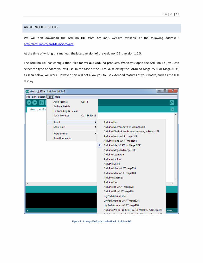
The Arduino IDE has configuration files for various Arduino products. When you open the Arduino IDE, you can
select the type of board you will use. In the case of the RAMBo, selecting the "Arduino Mega 2560 or Mega ADK",
as seen below, will work. However, this will not allow you to use extended features of your board, such as the LCD
display.
Figure 5 - Atmega2560 board selection in Arduino IDE

P a g e | 14
In order to use the LCD and take advantage of the full capabilities of the RAMBo, we will install an Arduino Addon
for RAMbo by downloading it from the following URL :
http://reprapelectro.com/wp-content/uploads/2014/07/Arduino_1.x.x.zip
Once you extract the zip file of the Arduino Addon, you will find in it a directory named rambo, you will need to
copy that directory to the hardware directory of the Arduino installation.
Notice on the left of the above image, the full path of the directory in which we copied the rambo directory from
the Arduino_1.x.x. On your system, the path may be different, but it will often be :
C:\Program Files (x86)\Arduino\hardware
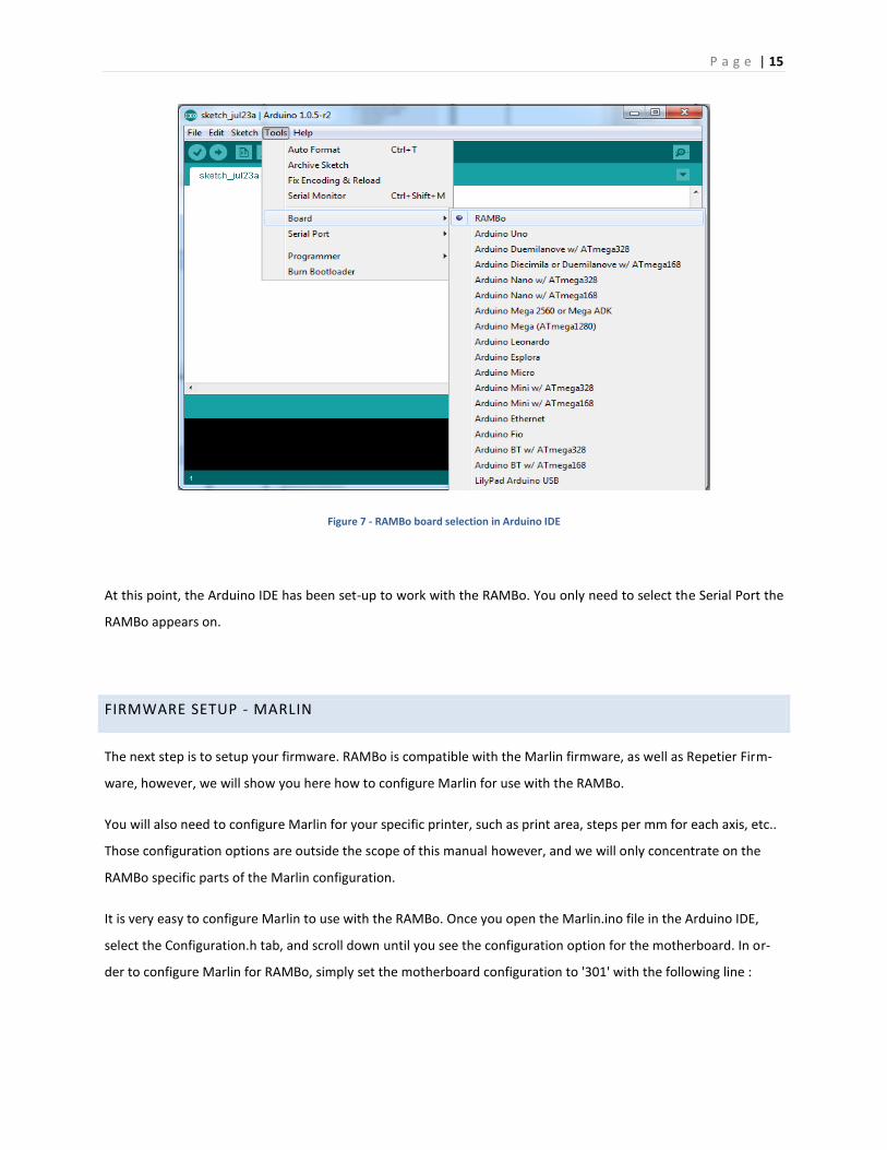
Once the rambo directory is copied, you can close the Arduino IDE and re-open it. You can now select RAMBo as a
choice of board from the Tools menu.
Figure 6 - Copy Arduino Addons rambo directory to Arduino/hardware directory
P a g e | 15
Figure 7 - RAMBo board selection in Arduino IDE
At this point, the Arduino IDE has been set-up to work with the RAMBo. You only need to select the Serial Port the
RAMBo appears on.
FIRMWARE SETUP - MARLIN
The next step is to setup your firmware. RAMBo is compatible with the Marlin firmware, as well as Repetier Firm-
ware, however, we will show you here how to configure Marlin for use with the RAMBo.
You will also need to configure Marlin for your specific printer, such as print area, steps per mm for each axis, etc..
Those configuration options are outside the scope of this manual however, and we will only concentrate on the
RAMBo specific parts of the Marlin configuration.
It is very easy to configure Marlin to use with the RAMBo. Once you open the Marlin.ino file in the Arduino IDE,
select the Configuration.h tab, and scroll down until you see the configuration option for the motherboard. In or-
der to configure Marlin for RAMBo, simply set the motherboard configuration to '301' with the following line :
P a g e | 16
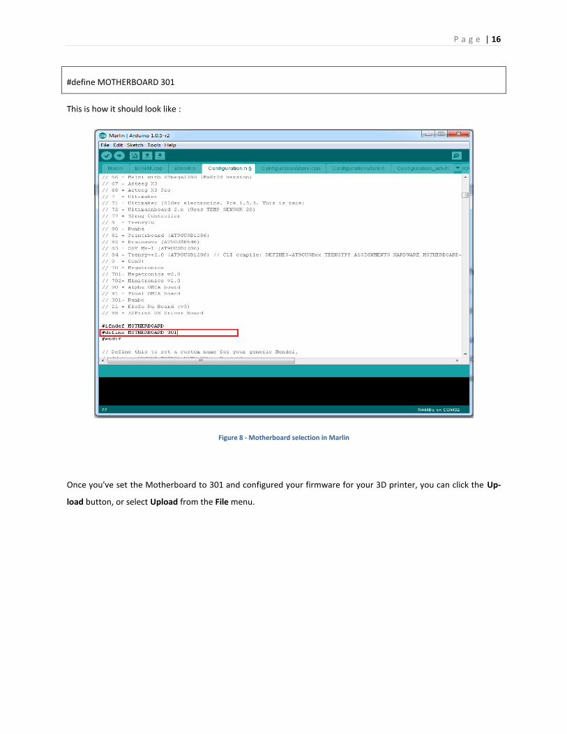
#define MOTHERBOARD 301
This is how it should look like :
Figure 8 - Motherboard selection in Marlin
Once you've set the Motherboard to 301 and configured your firmware for your 3D printer, you can click the Up-
load button, or select Upload from the File menu.

P a g e | 17
Figure 9 - Upload button in toolbar
This will compile the firmware and upload it to the RAMBo.
If you need to add support for an LCD display, such as the RepRapDiscount Smart LCD Controller, you will need to
have your board type set to RAMBo and Arduino IDE configured correctly as explained in the previous section,
then you will need to update some files from the Marlin firmware.
If you are using the latest git version or any version from August 4th 2013 and later, then you don't need to modify
the Marlin firmware for using the LCD, if you use however an older version of the Marlin firmware and do not wish
to update to a more recent one, or if you are simply unsure, then you will need to overwrite the fastio.h and pins.h
files from the Marlin directory with the latest version of those files available from github :
https://raw.githubusercontent.com/ErikZalm/Marlin/Marlin_v1/Marlin/pins.h
https://raw.githubusercontent.com/ErikZalm/Marlin/Marlin_v1/Marlin/fastio.h

P a g e | 18
Simply download those two files and copy them to the Marlin directory, overwriting the previous files.
You can now configure the Marlin firmware to use the LCD controller that you have and it will work with the
RAMBo as long as it is wired correctly (See the relevant section of this manual for instructions on how to wire the
LCD controller to the RAMBo).
Don't forget to install the U8glib library to the Arduino IDE installation directory if you use the Full Graphics Smart
LCD Controller, as instructed in Marlin's Configuration.h file. To do so, copy the U8glib directory which you can find
in the Marlin directory under the Marlin/ArduinoAddons/Arduino_1.x.x/libraries/ subdirectory into the Arduino's
libraries directory (C:\Program Files (x86)\Arduino\libraries).

P a g e | 19
HARDWARE SETUP
Connecting the RAMBo to your 3d printer is relatively straightforward. You may need to prepare some of the wires
with the provided housings prior to connecting them to the RAMBo. All of RAMBo's connectors are easy to use
with a clipping system preventing the cables from falling and allowing you to remove them without effort by press-
ing lightly on the connector.
The accessories bag that comes with the RAMBo has a set of connector housings and female crimp pins that you
can use to create RAMBo compatible wires for your motors, a set of wires for your thermistors and a set of
endstops and a wire harness that are pre-crimped and ready to use. The accessories bag also contains 2-pin plug-
gable and 6-pin pluggable connectors for the mosfets and power input respectively as well as a USB cable. De-
pending on your source, it may also come with the SmartLCD Adapter.
Figure 10 - Labeled accessories of RAMBo
P a g e | 20
CABLE PREPARATION
MOTORS
Your stepper motors use four wires and will usually come with a 4 pin connector. It is possible that the 4 pin con-
nector of your motors will fit in the RAMBo connectors, in which case you can choose to leave it as is or change the
connector to the RAMBo supplied ones. It is also possible that the 4 pin connector of your motors will simply not fit
in the RAMBo connectors, in which case you will need to change the connector of the motor's wires. Note however
that if you leave the motor wire with its original connector, that the insertion and removal of the connector will
not be as easy as if you used the RAMBo connectors.
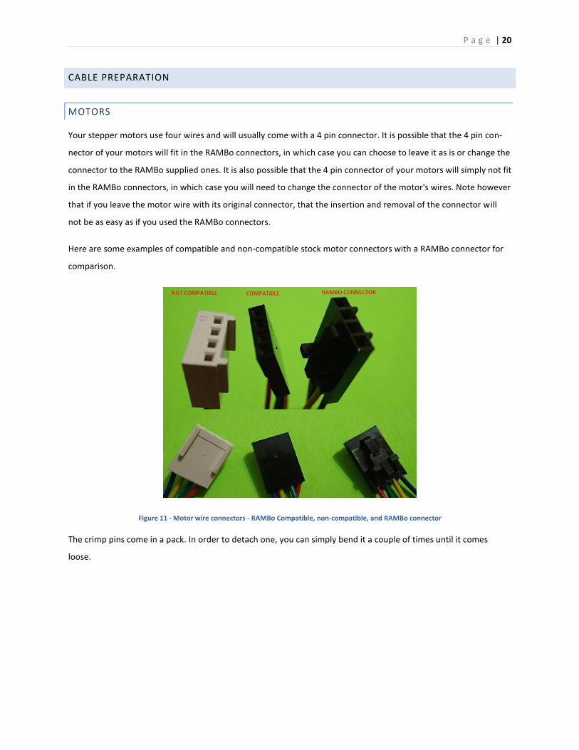
Here are some examples of compatible and non-compatible stock motor connectors with a RAMBo connector for
comparison.
Figure 11 - Motor wire connectors - RAMBo Compatible, non-compatible, and RAMBo connector
The crimp pins come in a pack. In order to detach one, you can simply bend it a couple of times until it comes
loose.

P a g e | 21
Figure 12 - Crimp pins
First, you need to detach a crimp pin from the supplied pack and inspect it, you should see two pairs of tabs at one
end of the crimp pin, one pair slightly larger than the other. The tabs at the end of the pin are called insulation
crimp and are used for stress relief by holding the insulation of the wire, while the larger tabs are called conductor
crimp and are used for making contact with the wire itself. There will also be a locking tang that will hold the crimp
in place inside the connector housing. Please familiarize yourself with the crimp pin before reading further.
Figure 13 - Crimp pin details
You can now cut the motor's wire just before the existing connector if there is one. Use a wire stripper to strip the
end of the insulation and reveal the copper wires beneath. You should only strip about 3mm (1/8") off the end of
the wire. Use one of the female crimp pins as reference for the length required, knowing that the wire shouldn't go
much beyond the conductor crimp of the pin, and the insulation should fit on the insulation crimp.

P a g e | 22
Figure 14 - Stripped wire positioned on crimp pin
You will need a good crimp tool in order to crimp the wire to the pin, you can get one from Pololu's store, for ex-
ample : http://www.pololu.com/product/1928
In the above link, you can also find instructions and links to two useful tutorial videos on how to crimp a wire with
the tool. We would strongly suggest you read the instructions and watch those two videos in order to get familiar
with the process : https://www.youtube.com/watch?v=K7Qb3DzIX3s and https://www.youtube.com/watch?
v=GkbOJSvhCgU#t=280
If you do not have a crimp tool and do not want to buy one, you can simply use needle-nose pliers, although the
process will be slightly slower, more complicated and will not yield as good as a result as if you used a proper crimp
tool. Use this video as a reference on how to crimp the pins with needle-nose pliers :
http://www.youtube.com/watch?v=jz_8w2XHKL8
Insert your stripped wire into the crimp pin, making sure the insulation crimps are aligned with the insulation and
the wire sits between the conductor crimps, then either use the crimp tool as explained in the above links, or, if
you're using needle-nose pliers, push down on each tab individually until you crimp the wire into the pin.
P a g e | 23
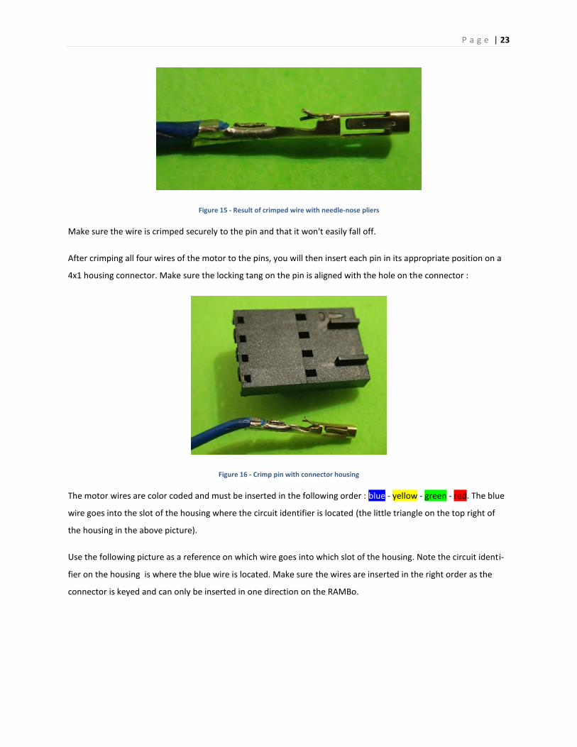
Figure 15 - Result of crimped wire with needle-nose pliers
Make sure the wire is crimped securely to the pin and that it won't easily fall off.
After crimping all four wires of the motor to the pins, you will then insert each pin in its appropriate position on a
4x1 housing connector. Make sure the locking tang on the pin is aligned with the hole on the connector :
Figure 16 - Crimp pin with connector housing
The motor wires are color coded and must be inserted in the following order : blue - yellow - green - red. The blue
wire goes into the slot of the housing where the circuit identifier is located (the little triangle on the top right of
the housing in the above picture).
Use the following picture as a reference on which wire goes into which slot of the housing. Note the circuit identi-
fier on the housing is where the blue wire is located. Make sure the wires are inserted in the right order as the
connector is keyed and can only be inserted in one direction on the RAMBo.
P a g e | 24
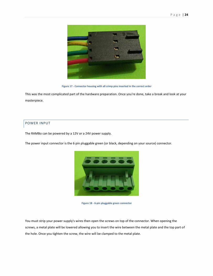
Figure 17 - Connector housing with all crimp pins inserted in the correct order
This was the most complicated part of the hardware preparation. Once you're done, take a break and look at your
masterpiece.
POWER INPUT
The RAMBo can be powered by a 12V or a 24V power supply.
The power input connector is the 6 pin pluggable green (or black, depending on your source) connector.
Figure 18 - 6-pin pluggable green connector
You must strip your power supply's wires then open the screws on top of the connector. When opening the
screws, a metal plate will be lowered allowing you to insert the wire between the metal plate and the top part of
the hole. Once you tighten the screw, the wire will be clamped to the metal plate.
P a g e | 25
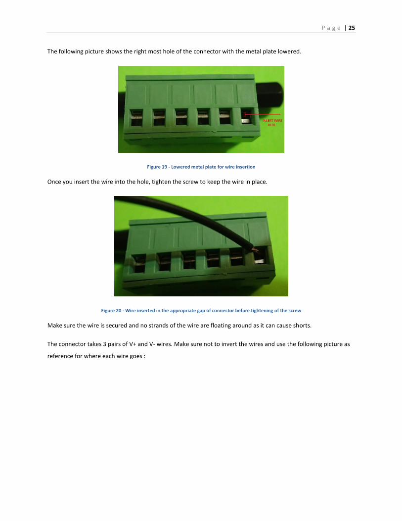
The following picture shows the right most hole of the connector with the metal plate lowered.
Figure 19 - Lowered metal plate for wire insertion
Once you insert the wire into the hole, tighten the screw to keep the wire in place.
Figure 20 - Wire inserted in the appropriate gap of connector before tightening of the screw
Make sure the wire is secured and no strands of the wire are floating around as it can cause shorts.
The connector takes 3 pairs of V+ and V- wires. Make sure not to invert the wires and use the following picture as
reference for where each wire goes :

P a g e | 26
Figure 21 - Labeled power connector with polarities
You should double check your wire connections and make sure the polarities are not inverted by inserting the un-
powered connector into the RAMBo and verifying the wires' polarities are aligned with the board's polarities :
Figure 22 - Inserted power connector with polarities
P a g e | 27
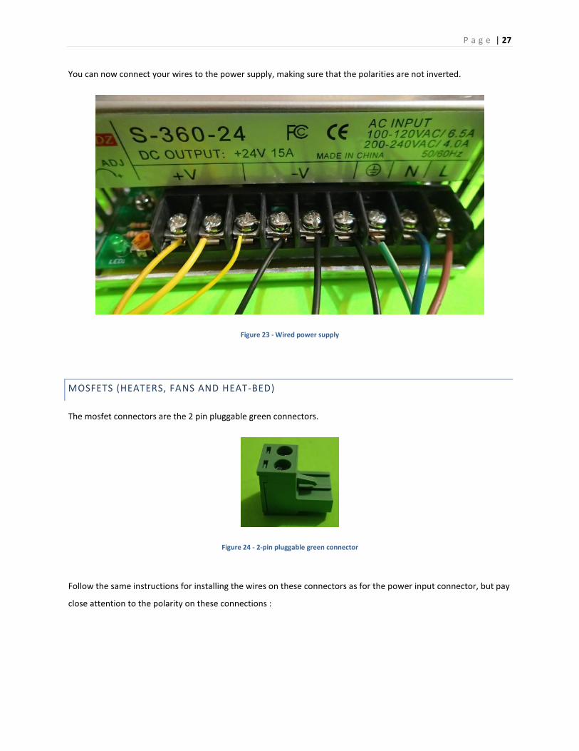
You can now connect your wires to the power supply, making sure that the polarities are not inverted.
Figure 23 - Wired power supply
MOSFETS (HEATERS, FANS AND HEAT-BED)
The mosfet connectors are the 2 pin pluggable green connectors.
Figure 24 - 2-pin pluggable green connector
Follow the same instructions for installing the wires on these connectors as for the power input connector, but pay
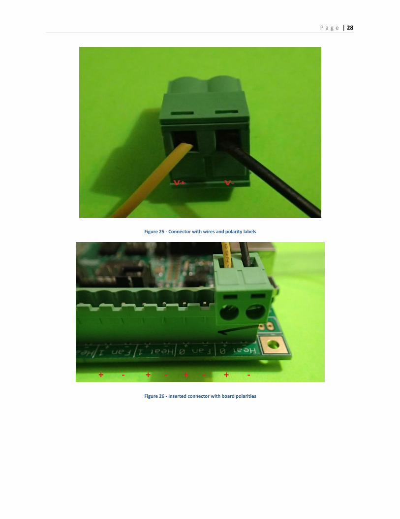
close attention to the polarity on these connections :
P a g e | 28
Figure 25 - Connector with wires and polarity labels
Figure 26 - Inserted connector with board polarities
P a g e | 29
THERMISTORS
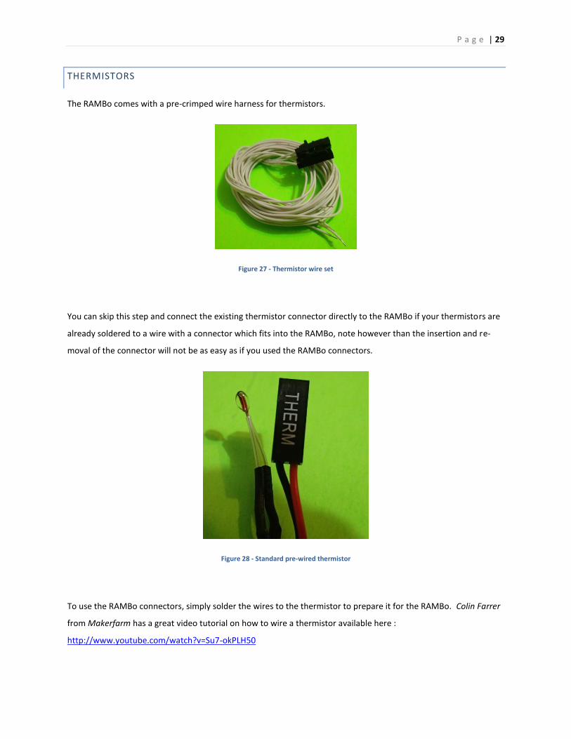
The RAMBo comes with a pre-crimped wire harness for thermistors.
Figure 27 - Thermistor wire set
You can skip this step and connect the existing thermistor connector directly to the RAMBo if your thermistors are
already soldered to a wire with a connector which fits into the RAMBo, note however than the insertion and re-
moval of the connector will not be as easy as if you used the RAMBo connectors.
Figure 28 - Standard pre-wired thermistor
To use the RAMBo connectors, simply solder the wires to the thermistor to prepare it for the RAMBo. Colin Farrer
from Makerfarm has a great video tutorial on how to wire a thermistor available here :
http://www.youtube.com/watch?v=Su7-okPLH50
P a g e | 30
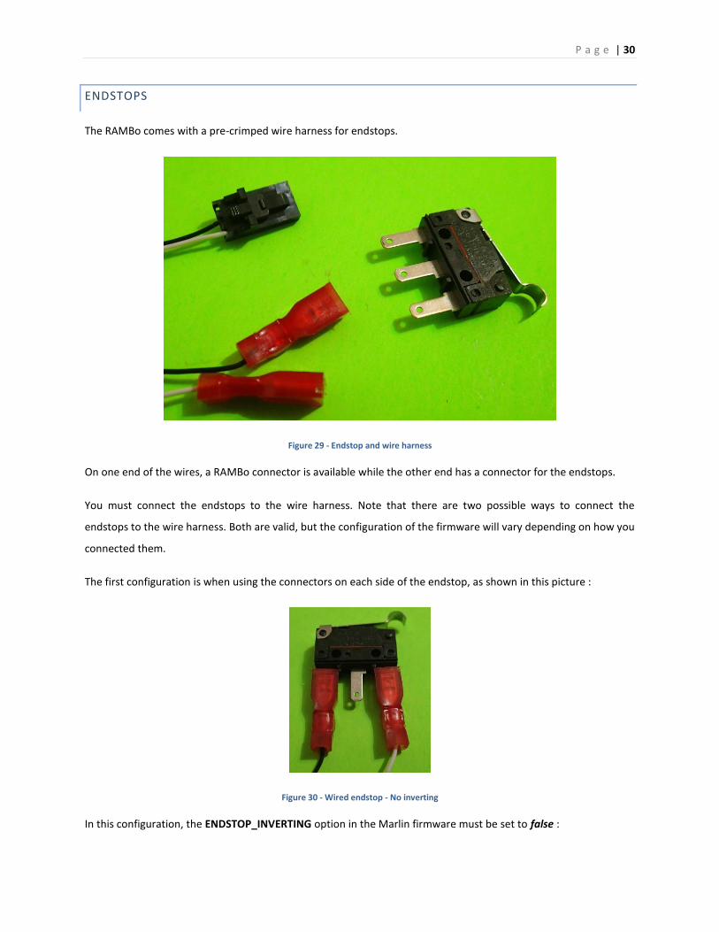
ENDSTOPS
The RAMBo comes with a pre-crimped wire harness for endstops.
Figure 29 - Endstop and wire harness
On one end of the wires, a RAMBo connector is available while the other end has a connector for the endstops.
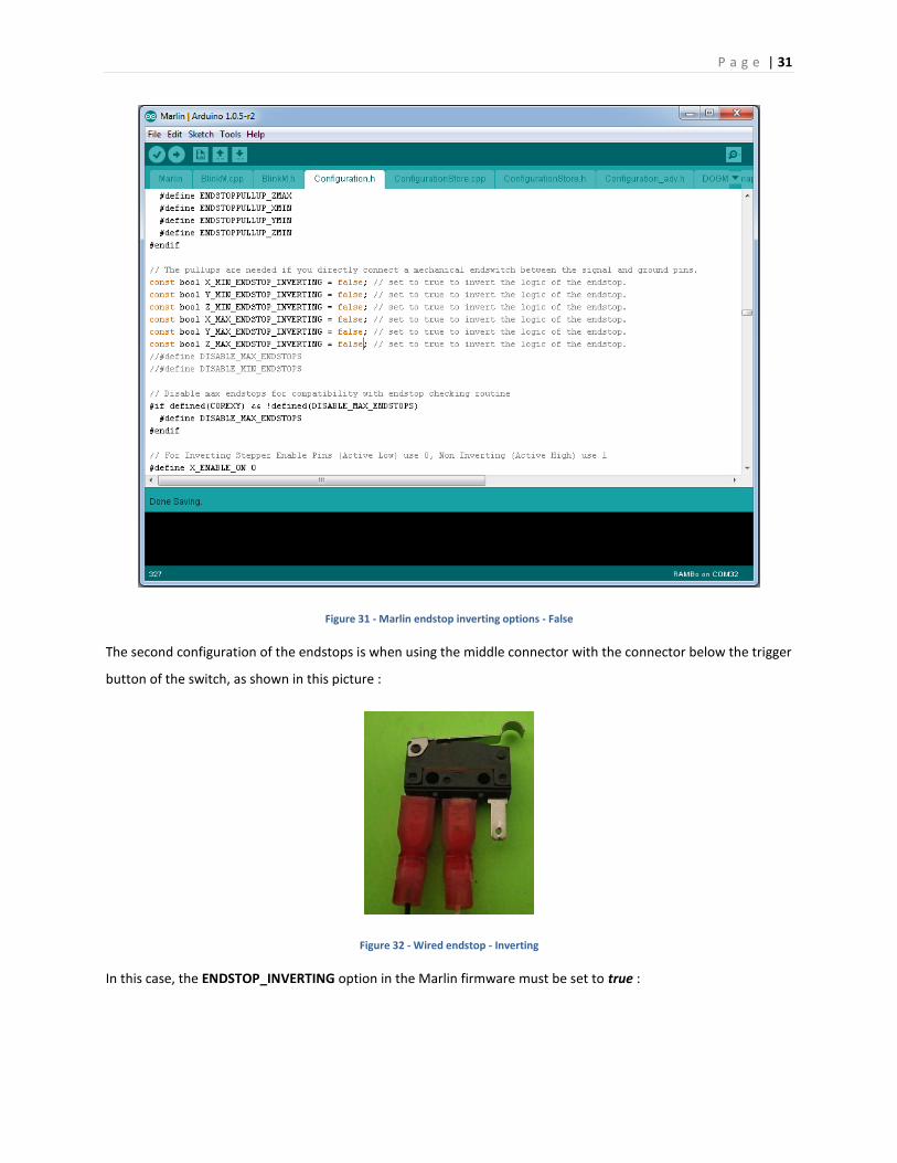
You must connect the endstops to the wire harness. Note that there are two possible ways to connect the
endstops to the wire harness. Both are valid, but the configuration of the firmware will vary depending on how you
connected them.
The first configuration is when using the connectors on each side of the endstop, as shown in this picture :
Figure 30 - Wired endstop - No inverting
In this configuration, the ENDSTOP_INVERTING option in the Marlin firmware must be set to false :
P a g e | 31
Figure 31 - Marlin endstop inverting options - False
The second configuration of the endstops is when using the middle connector with the connector below the trigger
button of the switch, as shown in this picture :
Figure 32 - Wired endstop - Inverting
In this case, the ENDSTOP_INVERTING option in the Marlin firmware must be set to true :

P a g e | 32
Figure 33 - Marlin endstop inverting options - True
P a g e | 33
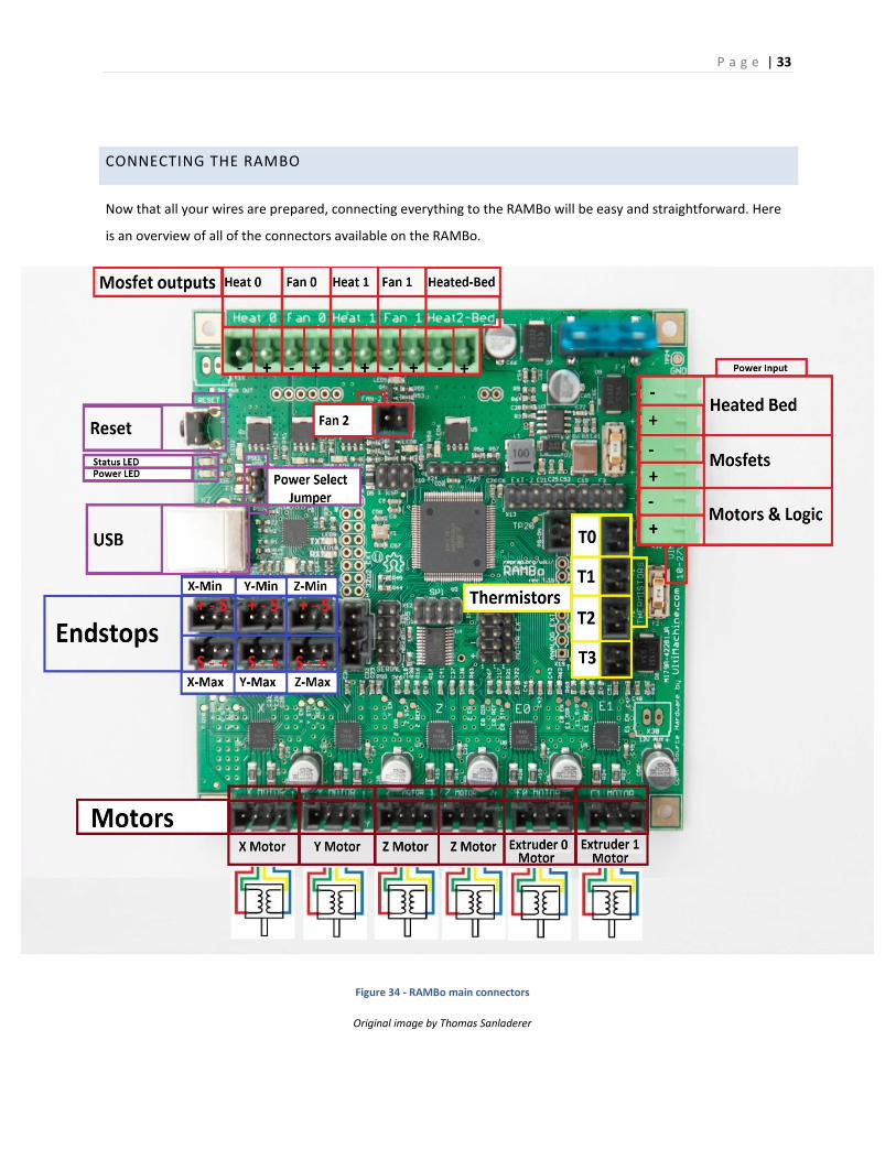
CONNECTING THE RAMBO
Now that all your wires are prepared, connecting everything to the RAMBo will be easy and straightforward. Here
is an overview of all of the connectors available on the RAMBo.
Figure 34 - RAMBo main connectors
Original image by Thomas Sanladerer

P a g e | 34
POWER INPUT
The RAMBo can be powered by a 12V or a 24V power supply.
The power connector is the green (or black) 6-pin connector on the right-hand side of the board marked with "VIN
10-27V" and with - and + polarities marked on the PCB :
Figure 35 - Power input connector
Image by Thomas Sanladerer
To connect power to the RAMBo, simply insert the 6-pin pluggable into the Power Input socket. As shown previ-
ously, make sure the polarity is not inverted.
Figure 36 - Power input connector with insert connectors

P a g e | 35
MOSFETS
To connect the heater, fans and heat-bed, insert the 2-pin pluggable in the appropriate mosfet connectors on the
board. There is also a FAN-2 standard connector below the row of mosfet connectors which can be used to control
a second fan.
Figure 37 - Mosfets
Image by Thomas Sanladerer
Note that the Heat-0, Fan-0, Heat-1 and Heat2-Bed connectors use high capacity mosfets and are suitable for pow-
ering heaters, however, the Fan-1 and Fan-2 connectors use low capacity mosfets which are more suited for pow-
ering fans rather than heaters. It is not recommended to connect any electronics that drains more than 2A of cur-
rent into the Fan-1 and Fan-2 connectors.
MOTORS
Connect the motors to the motor connectors on the bottom of the board. The blue wire must be towards the right
of the board (where the orientation of the board is with the 15A fuse holder on top and the USB connector to the
left) :
P a g e | 36
Figure 38 - Inserted motor connector
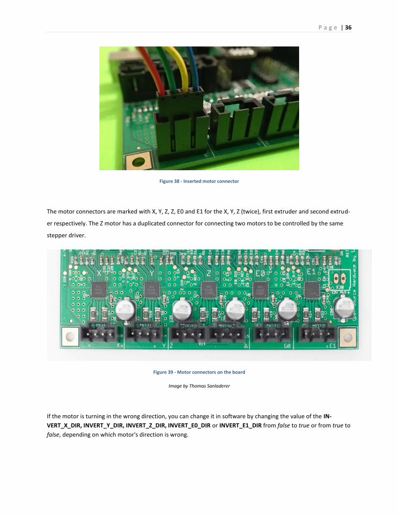
The motor connectors are marked with X, Y, Z, Z, E0 and E1 for the X, Y, Z (twice), first extruder and second extrud-
er respectively. The Z motor has a duplicated connector for connecting two motors to be controlled by the same
stepper driver.
Figure 39 - Motor connectors on the board
Image by Thomas Sanladerer
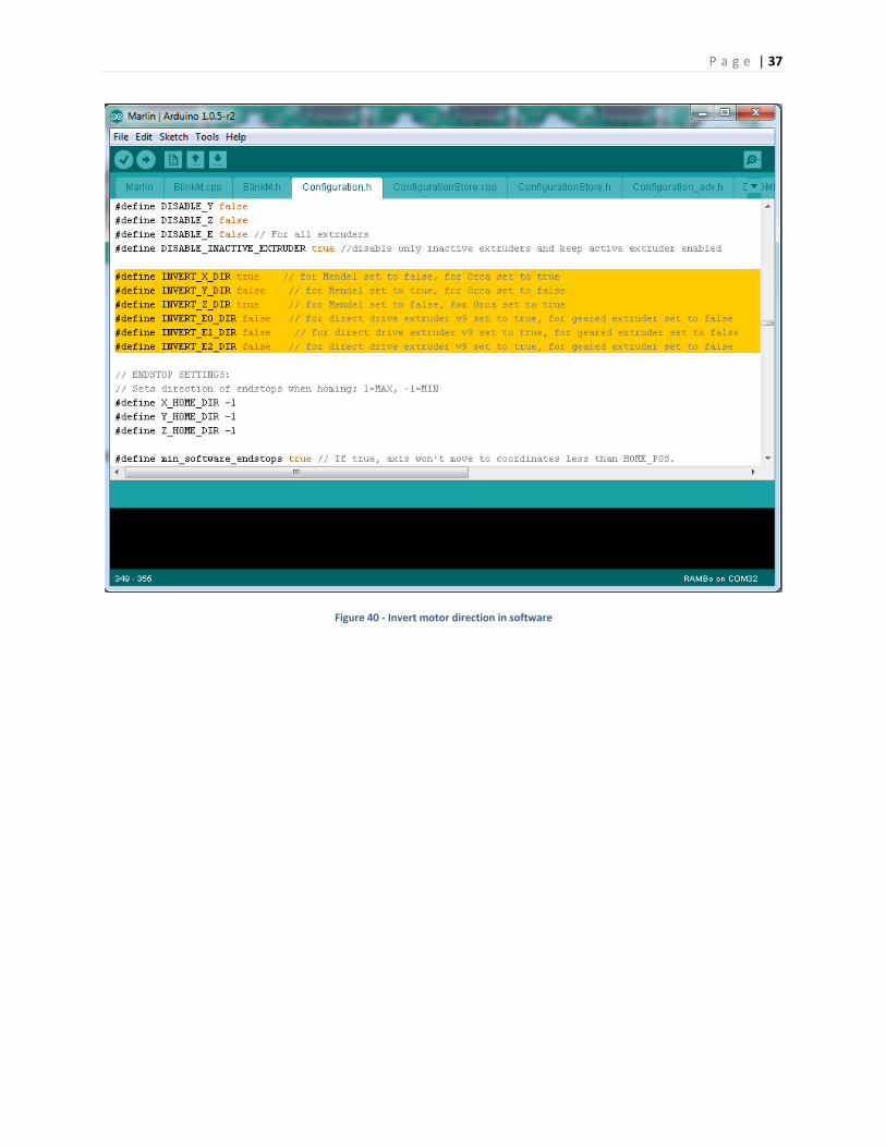
If the motor is turning in the wrong direction, you can change it in software by changing the value of the IN-
VERT_X_DIR, INVERT_Y_DIR, INVERT_Z_DIR, INVERT_E0_DIR or INVERT_E1_DIR from false to true or from true to
false, depending on which motor's direction is wrong.
P a g e | 37
Figure 40 - Invert motor direction in software
P a g e | 38
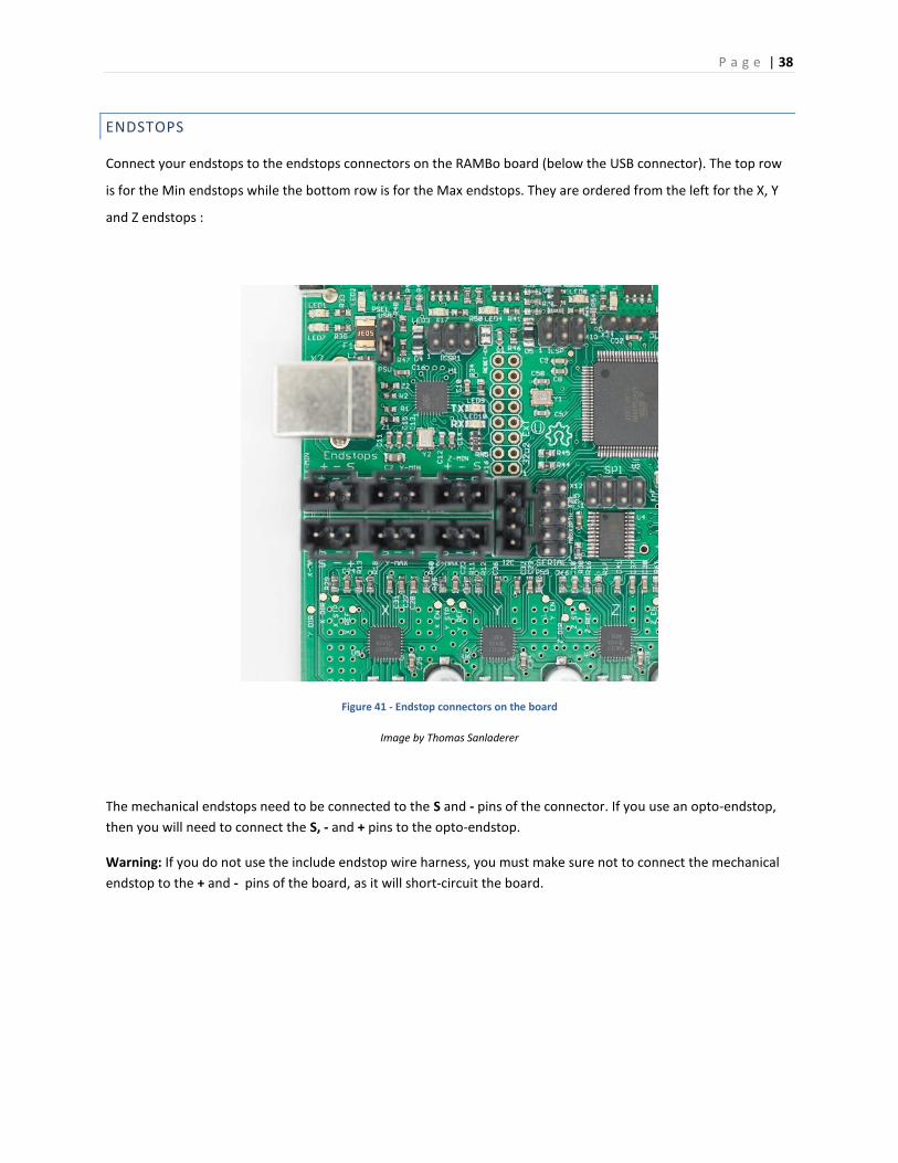
ENDSTOPS
Connect your endstops to the endstops connectors on the RAMBo board (below the USB connector). The top row
is for the Min endstops while the bottom row is for the Max endstops. They are ordered from the left for the X, Y
and Z endstops :
Figure 41 - Endstop connectors on the board
Image by Thomas Sanladerer
The mechanical endstops need to be connected to the S and - pins of the connector. If you use an opto-endstop,
then you will need to connect the S, - and + pins to the opto-endstop.
Warning: If you do not use the include endstop wire harness, you must make sure not to connect the mechanical
endstop to the + and - pins of the board, as it will short-circuit the board.
P a g e | 39
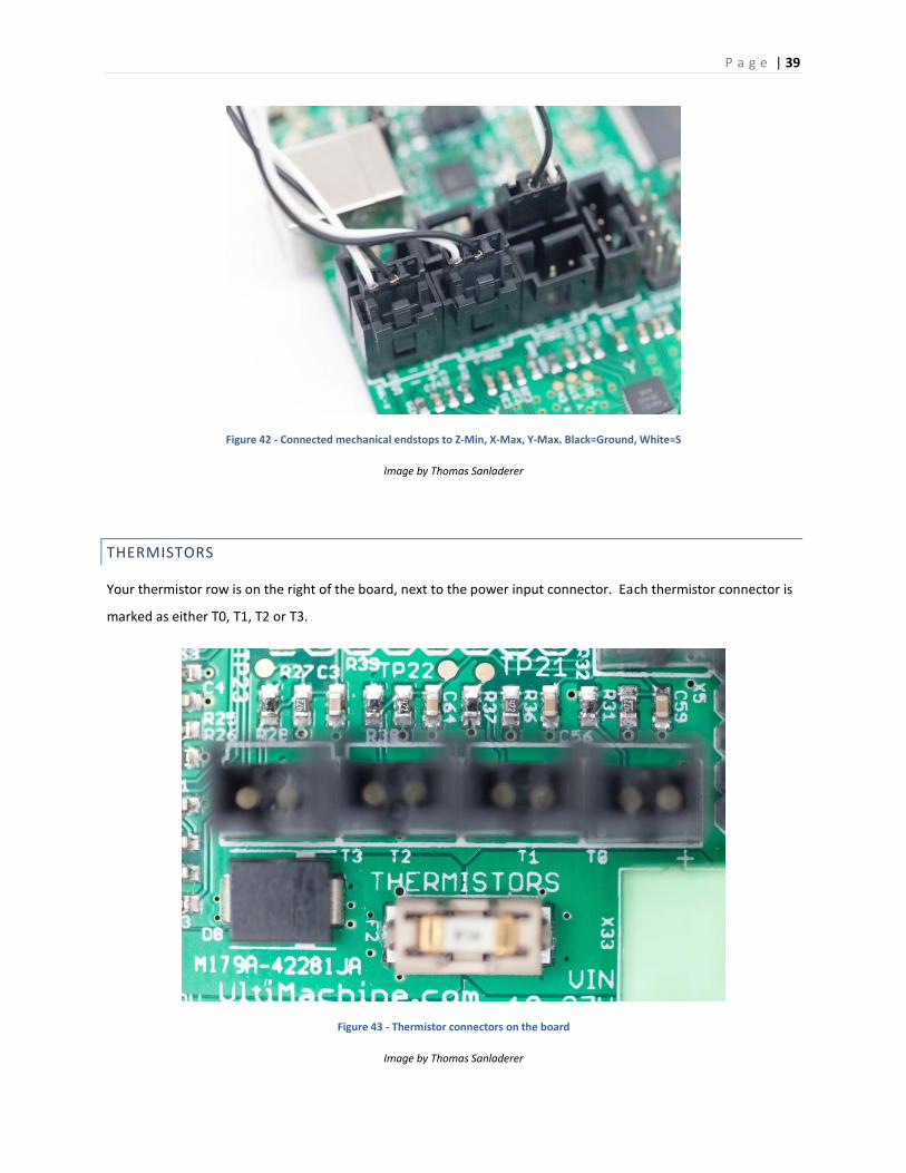
Figure 42 - Connected mechanical endstops to Z-Min, X-Max, Y-Max. Black=Ground, White=S
Image by Thomas Sanladerer
THERMISTORS
Your thermistor row is on the right of the board, next to the power input connector. Each thermistor connector is
marked as either T0, T1, T2 or T3.
Figure 43 - Thermistor connectors on the board
Image by Thomas Sanladerer
P a g e | 40
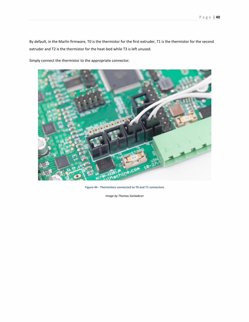
By default, in the Marlin firmware, T0 is the thermistor for the first extruder, T1 is the thermistor for the second
extruder and T2 is the thermistor for the heat-bed while T3 is left unused.
Simply connect the thermistor to the appropriate connector.
Figure 44 - Thermistors connected to T0 and T1 connectors
Image by Thomas Sanladerer
P a g e | 41
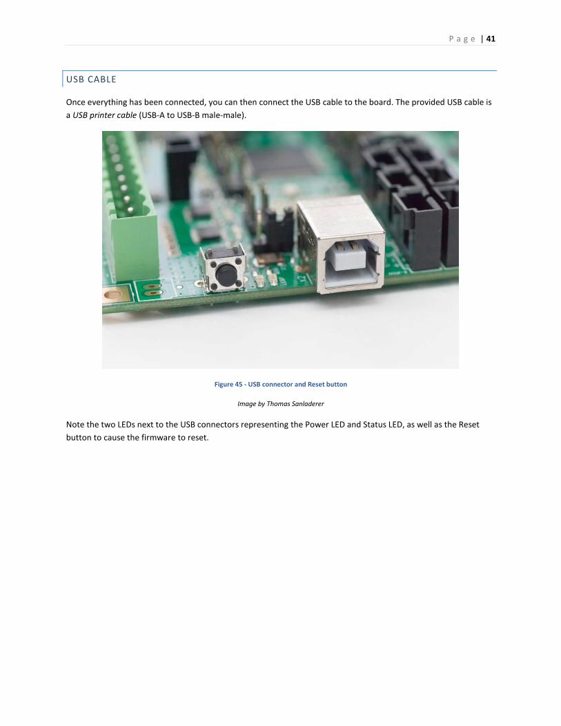
USB CABLE
Once everything has been connected, you can then connect the USB cable to the board. The provided USB cable is
a USB printer cable (USB-A to USB-B male-male).
Figure 45 - USB connector and Reset button
Image by Thomas Sanladerer
Note the two LEDs next to the USB connectors representing the Power LED and Status LED, as well as the Reset
button to cause the firmware to reset.
P a g e | 42
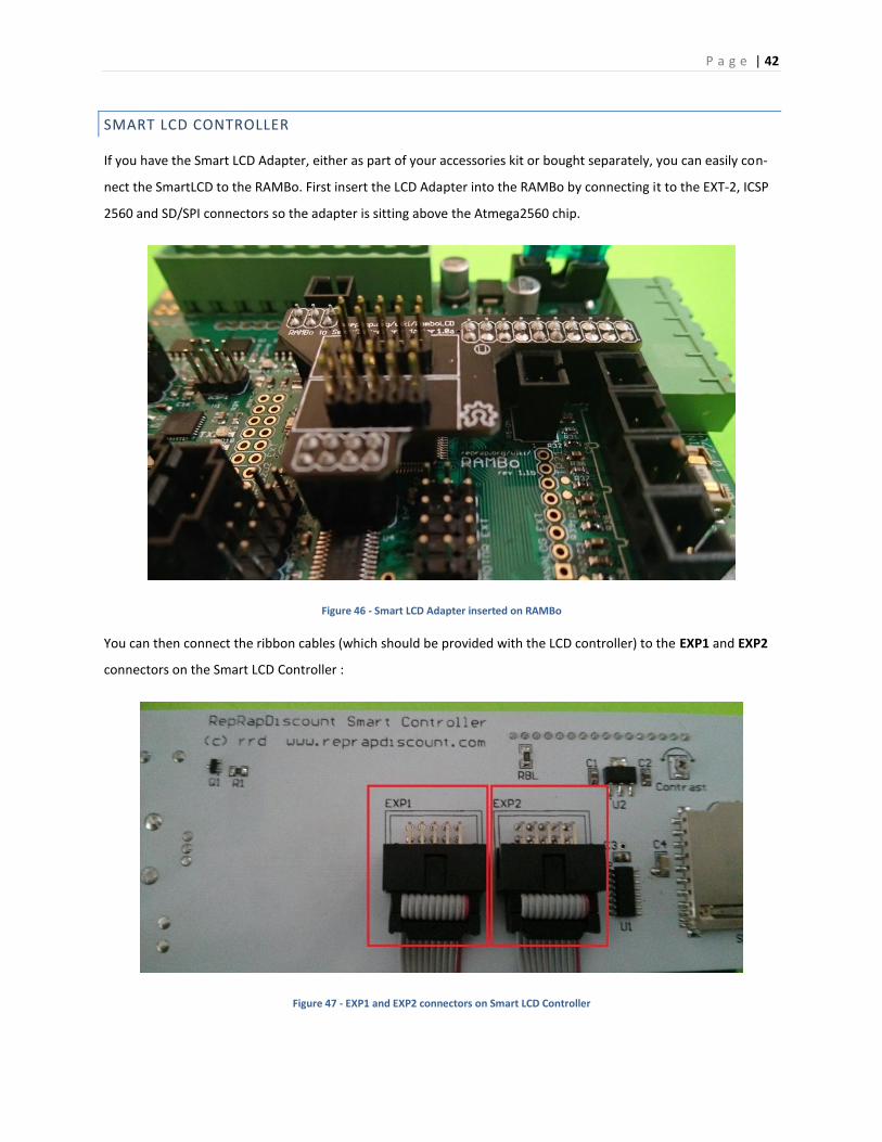
SMART LCD CONTROLLER
If you have the Smart LCD Adapter, either as part of your accessories kit or bought separately, you can easily con-
nect the SmartLCD to the RAMBo. First insert the LCD Adapter into the RAMBo by connecting it to the EXT-2, ICSP
2560 and SD/SPI connectors so the adapter is sitting above the Atmega2560 chip.
Figure 46 - Smart LCD Adapter inserted on RAMBo
You can then connect the ribbon cables (which should be provided with the LCD controller) to the EXP1 and EXP2
connectors on the Smart LCD Controller :
Figure 47 - EXP1 and EXP2 connectors on Smart LCD Controller
P a g e | 43
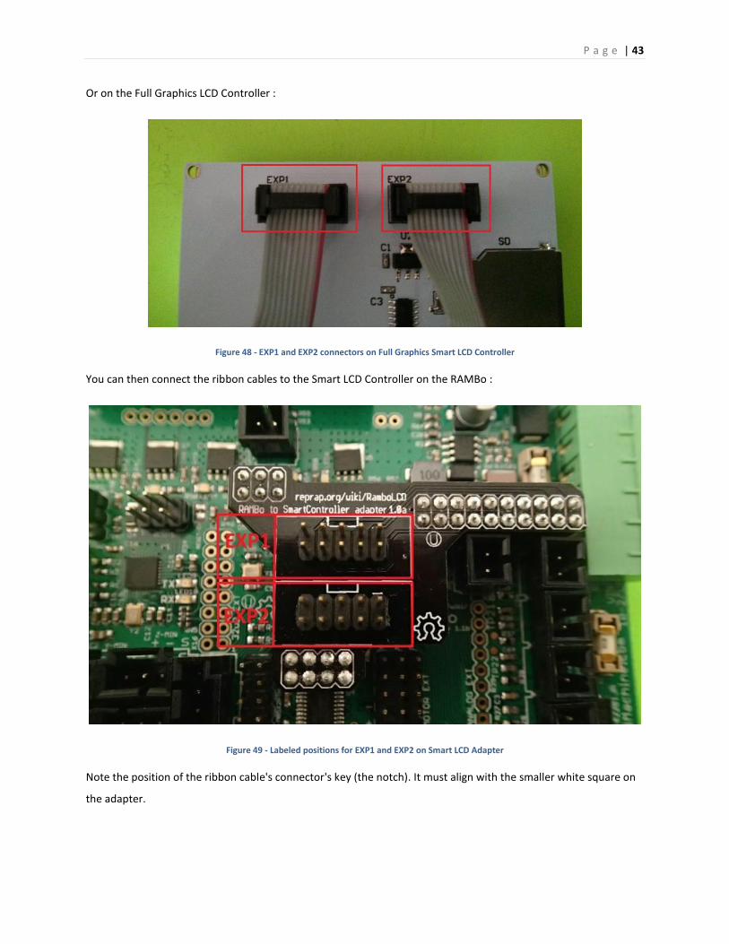
Or on the Full Graphics LCD Controller :
Figure 48 - EXP1 and EXP2 connectors on Full Graphics Smart LCD Controller
You can then connect the ribbon cables to the Smart LCD Controller on the RAMBo :
Figure 49 - Labeled positions for EXP1 and EXP2 on Smart LCD Adapter
Note the position of the ribbon cable's connector's key (the notch). It must align with the smaller white square on
the adapter.
P a g e | 44
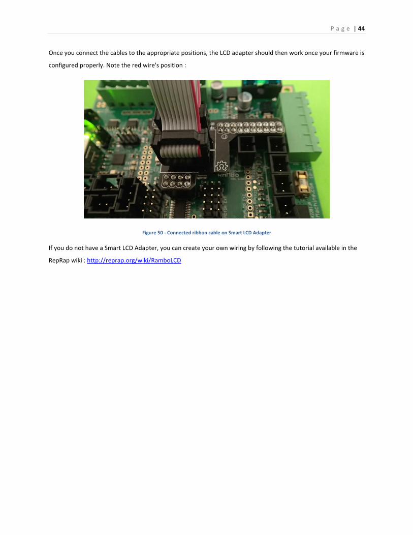
Once you connect the cables to the appropriate positions, the LCD adapter should then work once your firmware is
configured properly. Note the red wire's position :
Figure 50 - Connected ribbon cable on Smart LCD Adapter
If you do not have a Smart LCD Adapter, you can create your own wiring by following the tutorial available in the
RepRap wiki : http://reprap.org/wiki/RamboLCD
P a g e | 45
AUXILIARY CONNECTORS
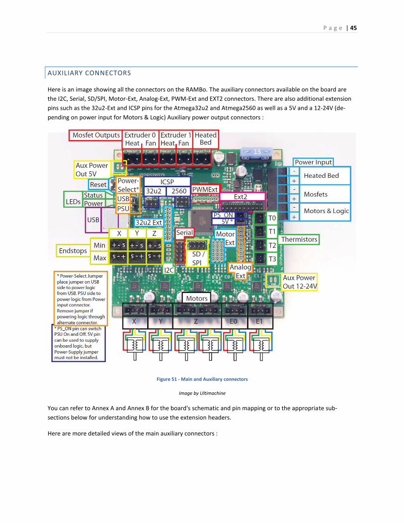
Here is an image showing all the connectors on the RAMBo. The auxiliary connectors available on the board are
the I2C, Serial, SD/SPI, Motor-Ext, Analog-Ext, PWM-Ext and EXT2 connectors. There are also additional extension
pins such as the 32u2-Ext and ICSP pins for the Atmega32u2 and Atmega2560 as well as a 5V and a 12-24V (de-
pending on power input for Motors & Logic) Auxiliary power output connectors :
Figure 51 - Main and Auxiliary connectors
Image by Ultimachine
You can refer to Annex A and Annex B for the board's schematic and pin mapping or to the appropriate sub-
sections below for understanding how to use the extension headers.
Here are more detailed views of the main auxiliary connectors :

P a g e | 46
Figure 52 - I2C, Serial, SD/SPI, Motor-Ext pins
Image by Thomas Sanladerer
Figure 53 - PWM and EXT-2 pins
Image by Thomas Sanladerer
P a g e | 47
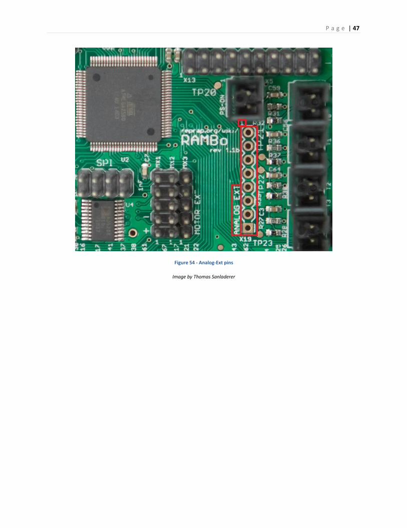
Figure 54 - Analog-Ext pins
Image by Thomas Sanladerer
P a g e | 48
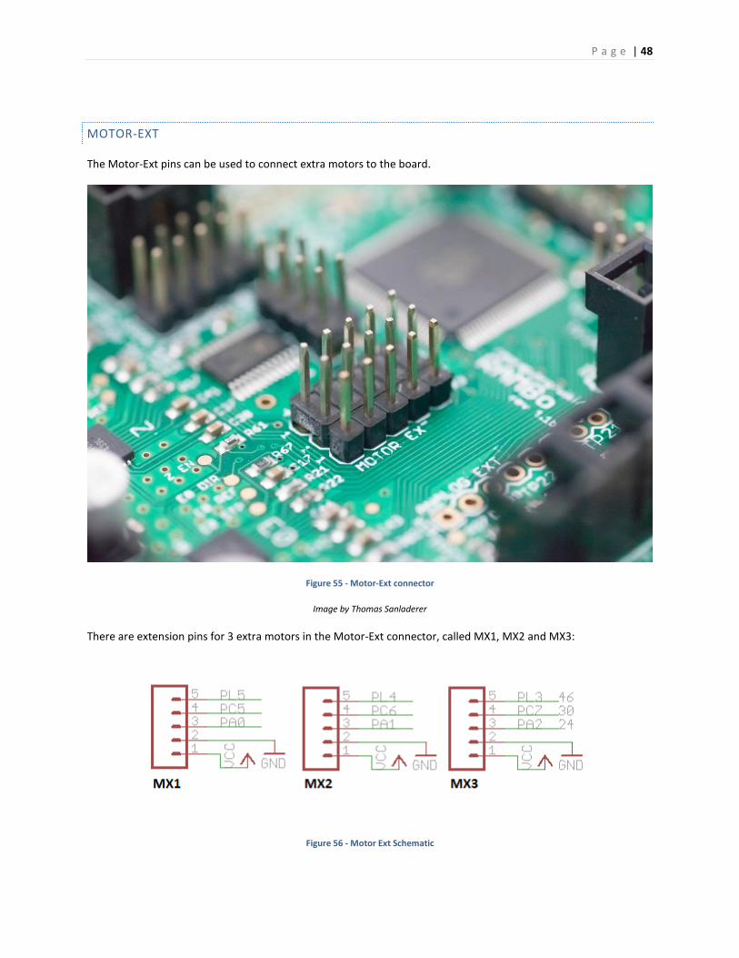
MOTOR-EXT
The Motor-Ext pins can be used to connect extra motors to the board.
Figure 55 - Motor-Ext connector
Image by Thomas Sanladerer
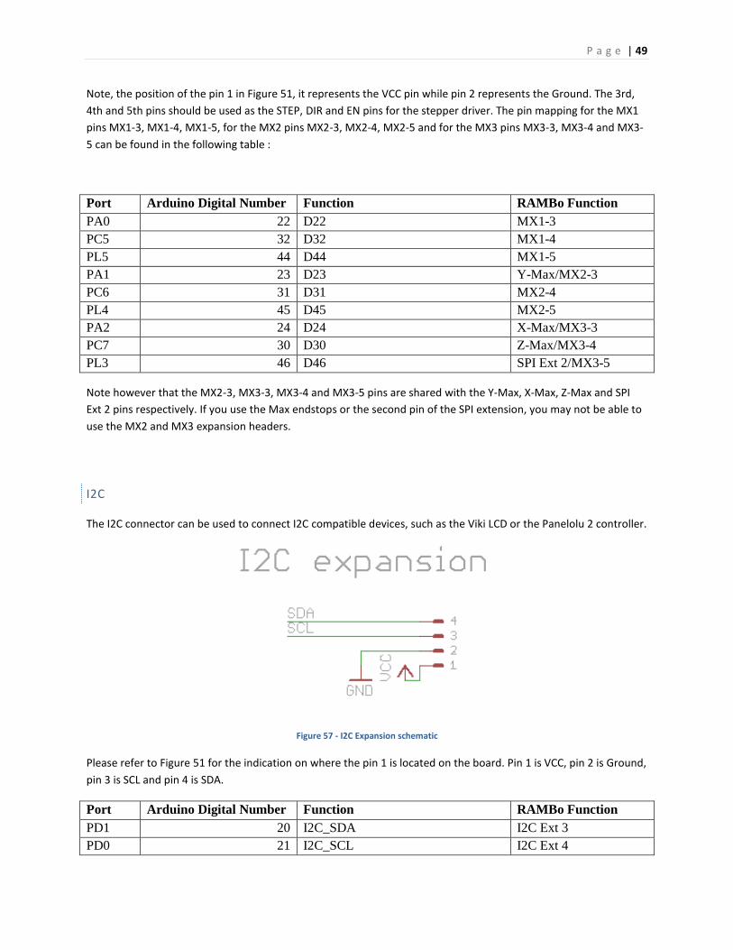
There are extension pins for 3 extra motors in the Motor-Ext connector, called MX1, MX2 and MX3:
Figure 56 - Motor Ext Schematic
P a g e | 49
Note, the position of the pin 1 in Figure 51, it represents the VCC pin while pin 2 represents the Ground. The 3rd,
4th and 5th pins should be used as the STEP, DIR and EN pins for the stepper driver. The pin mapping for the MX1
pins MX1-3, MX1-4, MX1-5, for the MX2 pins MX2-3, MX2-4, MX2-5 and for the MX3 pins MX3-3, MX3-4 and MX3-
5 can be found in the following table :
Port Arduino Digital Number Function RAMBo Function
PA0 22 D22 MX1-3
PC5 32 D32 MX1-4
PL5 44 D44 MX1-5
PA1 23 D23 Y-Max/MX2-3
PC6 31 D31 MX2-4
PL4 45 D45 MX2-5
PA2 24 D24 X-Max/MX3-3
PC7 30 D30 Z-Max/MX3-4
PL3 46 D46 SPI Ext 2/MX3-5
Note however that the MX2-3, MX3-3, MX3-4 and MX3-5 pins are shared with the Y-Max, X-Max, Z-Max and SPI
Ext 2 pins respectively. If you use the Max endstops or the second pin of the SPI extension, you may not be able to
use the MX2 and MX3 expansion headers.
I2C
The I2C connector can be used to connect I2C compatible devices, such as the Viki LCD or the Panelolu 2 controller.
Figure 57 - I2C Expansion schematic
Please refer to Figure 51 for the indication on where the pin 1 is located on the board. Pin 1 is VCC, pin 2 is Ground,
pin 3 is SCL and pin 4 is SDA.
Port Arduino Digital Number Function RAMBo Function
PD1 20 I2C_SDA I2C Ext 3
PD0 21 I2C_SCL I2C Ext 4

P a g e | 50
SERIAL
The Serial connector can be used to communicate using with the Atmega2560 chip over UART.
Figure 58 - Serial Extension Schematic
Here is the pin mapping for the Serial extension. You will notice that the Serial-Ext3 and Serial-Ext4 are used to
communicate with the USB connection.
Port Arduino Digital Number Function RAMBo Function
PE0 0 USART0_RX USB/Serial Ext 3
PE1 1 USART0_TX USB/Serial Ext 4
PD2 19 USART1_RX Serial Ext 5
PD3 18 USART1_TX Serial Ext 6
PH0 17 USART2_RX Serial Ext 7
PH1 16 USART2_TX Serial Ext 8
PJ0 15 USART3_RX Serial Ext 9
PJ1 14 USART3_TX Serial Ext 10
P a g e | 51
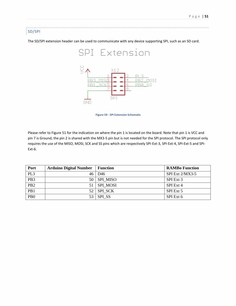
SD/SPI
The SD/SPI extension header can be used to communicate with any device supporting SPI, such as an SD card.
Figure 59 - SPI Extension Schematic
Please refer to Figure 51 for the indication on where the pin 1 is located on the board. Note that pin 1 is VCC and
pin 7 is Ground, the pin 2 is shared with the MX3-5 pin but is not needed for the SPI protocol. The SPI protocol only
requires the use of the MISO, MOSI, SCK and SS pins which are respectively SPI-Ext-3, SPI-Ext-4, SPI-Ext-5 and SPI-
Ext-6.
Port Arduino Digital Number Function RAMBo Function
PL3 46 D46 SPI Ext 2/MX3-5
PB3 50 SPI_MISO SPI Ext 3
PB2 51 SPI_MOSI SPI Ext 4
PB1 52 SPI_SCK SPI Ext 5
PB0 53 SPI_SS SPI Ext 6

P a g e | 52
PWM-EXT
The PWM-Ext header can be used as a general purpose PWM extension. It can be used for example to control ser-
vo motors for auto bed leveling.
Figure 60 - PWM Extension Schematic
Please refer to Figure 52 for the position of the pin 1 on the Board. The PWM Extension header shares some pins
with other features of the board: PWM-Ext-3 also controls the Status LED of the Baord, PWM-Ext-4 also controls
the Mosfet for the FAN-2 power output and PWM-Ext-6 also controls the PS-On pin.
Port Arduino Digital Number Function RAMBo Function
PB7 13 PWM13 LED/PWM Ext 3
PE4 2 PWM2 Fan-2/PWM Ext 4
PE3 5 PWM5 PWM Ext 5
PG5 4 PWM4 PS-On/PWM Ext 6
P a g e | 53
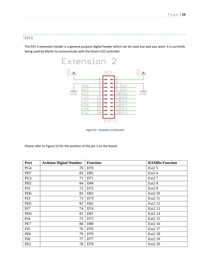
EXT2
The EXT-2 extension header is a general purpose digital header which can be used any way you want. It is currently
being used by Marlin to communicate with the Smart LCD controller.
Figure 61 - Extension 2 Schematic
Please refer to Figure 52 for the position of the pin 1 on the board.
Port Arduino Digital Number Function RAMBo Function
PG4 70 D70 Ext2 5
PH7 85 D85 Ext2 6
PG3 71 D71 Ext2 7
PH2 84 D84 Ext2 8
PJ2 72 D72 Ext2 9
PD6 83 D83 Ext2 10
PJ3 73 D73 Ext2 11
PD5 82 D82 Ext2 12
PJ7 74 D74 Ext2 13
PD4 81 D81 Ext2 14
PJ4 75 D75 Ext2 15
PE7 80 D80 Ext2 16
PJ5 76 D76 Ext2 17
PE6 79 D79 Ext2 18
PJ6 77 D77 Ext2 19
PE2 78 D78 Ext2 20
P a g e | 54
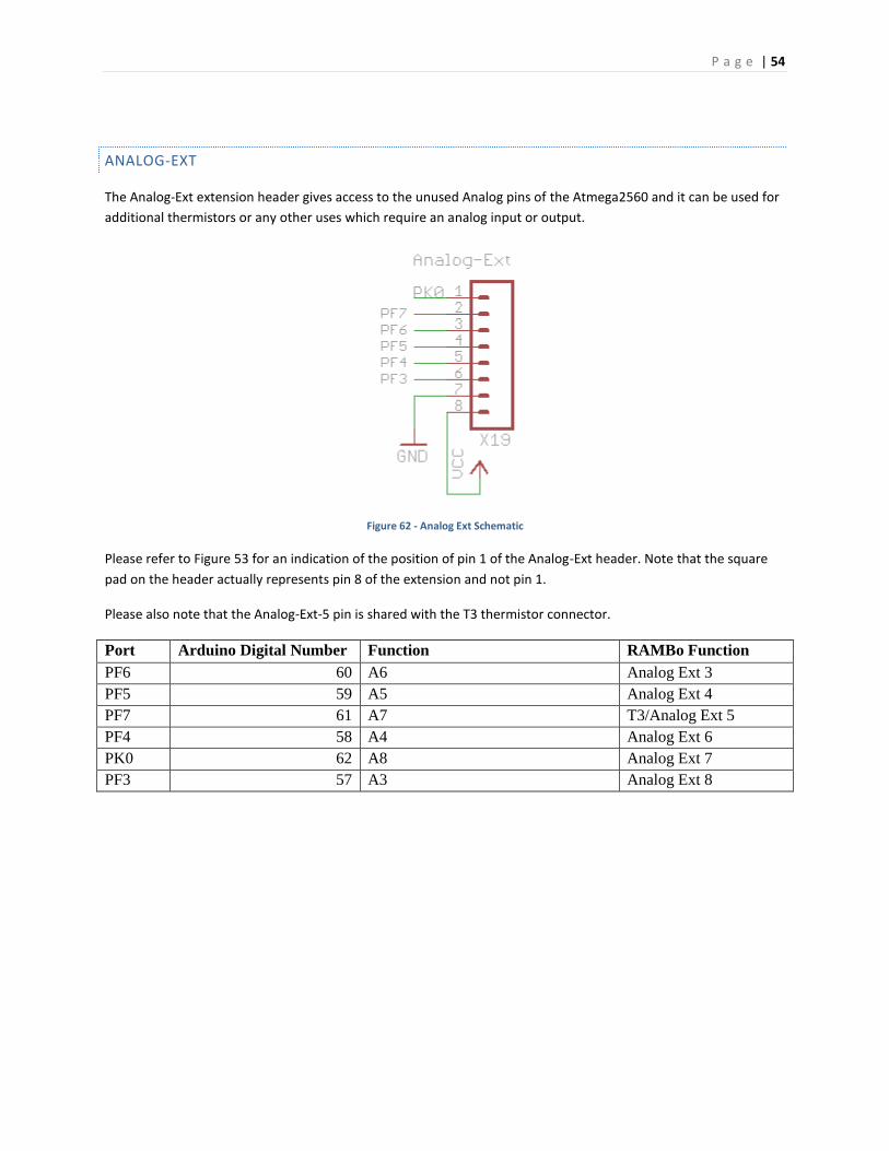
ANALOG-EXT
The Analog-Ext extension header gives access to the unused Analog pins of the Atmega2560 and it can be used for
additional thermistors or any other uses which require an analog input or output.
Figure 62 - Analog Ext Schematic
Please refer to Figure 53 for an indication of the position of pin 1 of the Analog-Ext header. Note that the square
pad on the header actually represents pin 8 of the extension and not pin 1.
Please also note that the Analog-Ext-5 pin is shared with the T3 thermistor connector.
Port Arduino Digital Number Function RAMBo Function
PF6 60 A6 Analog Ext 3
PF5 59 A5 Analog Ext 4
PF7 61 A7 T3/Analog Ext 5
PF4 58 A4 Analog Ext 6
PK0 62 A8 Analog Ext 7
PF3 57 A3 Analog Ext 8
P a g e | 55
CONFIGURATION AND TROUBLESHOOTING
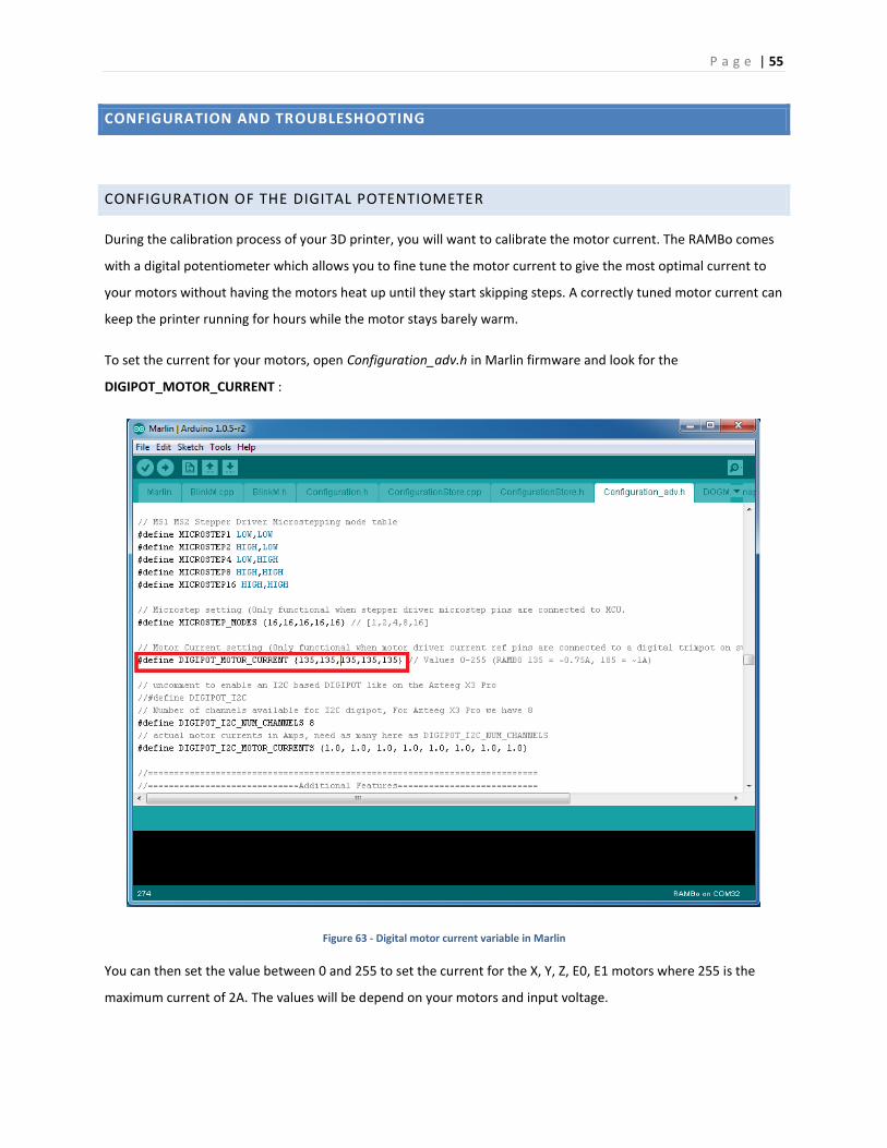
CONFIGURATION OF THE DIGITAL POTENTIOMETER
During the calibration process of your 3D printer, you will want to calibrate the motor current. The RAMBo comes
with a digital potentiometer which allows you to fine tune the motor current to give the most optimal current to
your motors without having the motors heat up until they start skipping steps. A correctly tuned motor current can
keep the printer running for hours while the motor stays barely warm.
To set the current for your motors, open Configuration_adv.h in Marlin firmware and look for the
DIGIPOT_MOTOR_CURRENT :
Figure 63 - Digital motor current variable in Marlin
You can then set the value between 0 and 255 to set the current for the X, Y, Z, E0, E1 motors where 255 is the
maximum current of 2A. The values will be depend on your motors and input voltage.
P a g e | 56
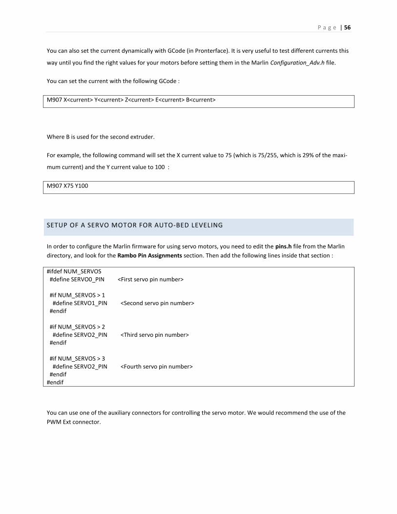
You can also set the current dynamically with GCode (in Pronterface). It is very useful to test different currents this
way until you find the right values for your motors before setting them in the Marlin Configuration_Adv.h file.
You can set the current with the following GCode :
M907 X<current> Y<current> Z<current> E<current> B<current>
Where B is used for the second extruder.
For example, the following command will set the X current value to 75 (which is 75/255, which is 29% of the maxi-
mum current) and the Y current value to 100 :
M907 X75 Y100
SETUP OF A SERVO MOTOR FOR AUTO-BED LEVELING
In order to configure the Marlin firmware for using servo motors, you need to edit the pins.h file from the Marlin
directory, and look for the Rambo Pin Assignments section. Then add the following lines inside that section :
#ifdef NUM_SERVOS #define SERVO0_PIN <First servo pin number> #if NUM_SERVOS > 1 #define SERVO1_PIN <Second servo pin number> #endif #if NUM_SERVOS > 2 #define SERVO2_PIN <Third servo pin number> #endif #if NUM_SERVOS > 3 #define SERVO2_PIN <Fourth servo pin number> #endif #endif
You can use one of the auxiliary connectors for controlling the servo motor. We would recommend the use of the
PWM Ext connector.
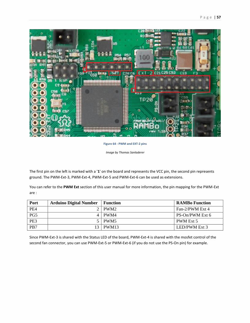
P a g e | 57
Figure 64 - PWM and EXT-2 pins
Image by Thomas Sanladerer
The first pin on the left is marked with a '1' on the board and represents the VCC pin, the second pin represents
ground. The PWM-Ext-3, PWM-Ext-4, PWM-Ext-5 and PWM-Ext-6 can be used as extensions.
You can refer to the PWM Ext section of this user manual for more information, the pin mapping for the PWM-Ext
are :
Port Arduino Digital Number Function RAMBo Function
PE4 2 PWM2 Fan-2/PWM Ext 4
PG5 4 PWM4 PS-On/PWM Ext 6
PE3 5 PWM5 PWM Ext 5
PB7 13 PWM13 LED/PWM Ext 3
Since PWM-Ext-3 is shared with the Status LED of the board, PWM-Ext-4 is shared with the mosfet control of the
second fan connector, you can use PWM-Ext-5 or PWM-Ext-6 (if you do not use the PS-On pin) for example.
P a g e | 58
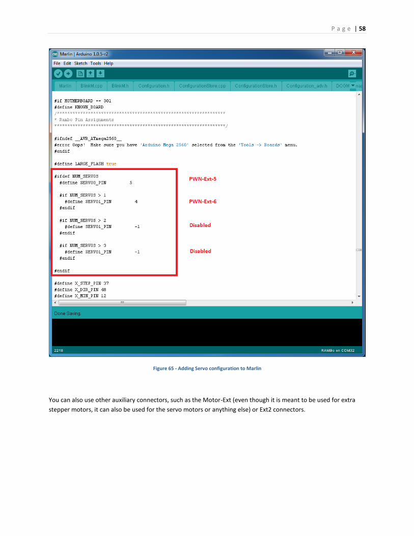
Figure 65 - Adding Servo configuration to Marlin
You can also use other auxiliary connectors, such as the Motor-Ext (even though it is meant to be used for extra
stepper motors, it can also be used for the servo motors or anything else) or Ext2 connectors.
P a g e | 59
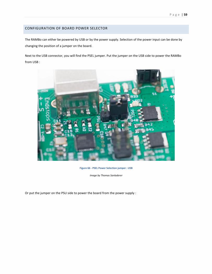
CONFIGURATION OF BOARD POWER SELECTOR
The RAMBo can either be powered by USB or by the power supply. Selection of the power input can be done by
changing the position of a jumper on the board.
Next to the USB connector, you will find the PSEL jumper. Put the jumper on the USB side to power the RAMBo
from USB :
Figure 66 - PSEL Power Selection jumper : USB
Image by Thomas Sanladerer
Or put the jumper on the PSU side to power the board from the power supply :

P a g e | 60
Figure 67 - PSEL Power Selection jumper : PSU
Image by Thomas Sanladerer
When the board is powered by the Power Supply, it will use the same power rails as the Motors.

P a g e | 61
REPLACING FUSES
The RAMBo controller uses three separate power rails, one for powering the heat-bed, one for the mosfets and
one for the motors and the board logic.
RAMBo has 3 replaceable fuses. In case of over-current or if power gets shorted, a fuse might be blown, in which
case, the heat-bed, mosfets or motors will stop working. You can replace the fuses easily, by buying compatible
fuses, removing the blown fuse from the board, either manually for the heat-bed fuse or by popping out the small
white fuses with a screwdriver and replacing them.
The small white fuse holders are Little Fuse OMNI-BLOCK fuse holders. They are compatible with NANO2 Fuses.
Fast or very fast acting are recommended. The fuses used in the retail RAMBo are rated at 5A with a maximum
voltage of 125V and an example part number for a replacement is 0448005.MR.
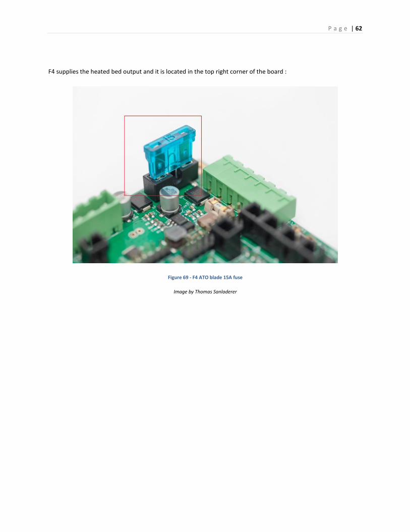
The heat-bed fuse F4 is an ATO (the type found in many automotives) rated at 15A with a maximum voltage of
32V. An example part number for a replacement is 0287015.PXCN.
F2 supplies the motors and on-board power supply. It is located next to the thermistor connectors. F3 supplies the
extruder heater and fan outputs. It is located next to the power input connector :
Figure 68 - F2 and F3 LittleFuse 5A fuses
Image by Thomas Sanladerer
P a g e | 62
F4 supplies the heated bed output and it is located in the top right corner of the board :
Figure 69 - F4 ATO blade 15A fuse
Image by Thomas Sanladerer
P a g e | 63
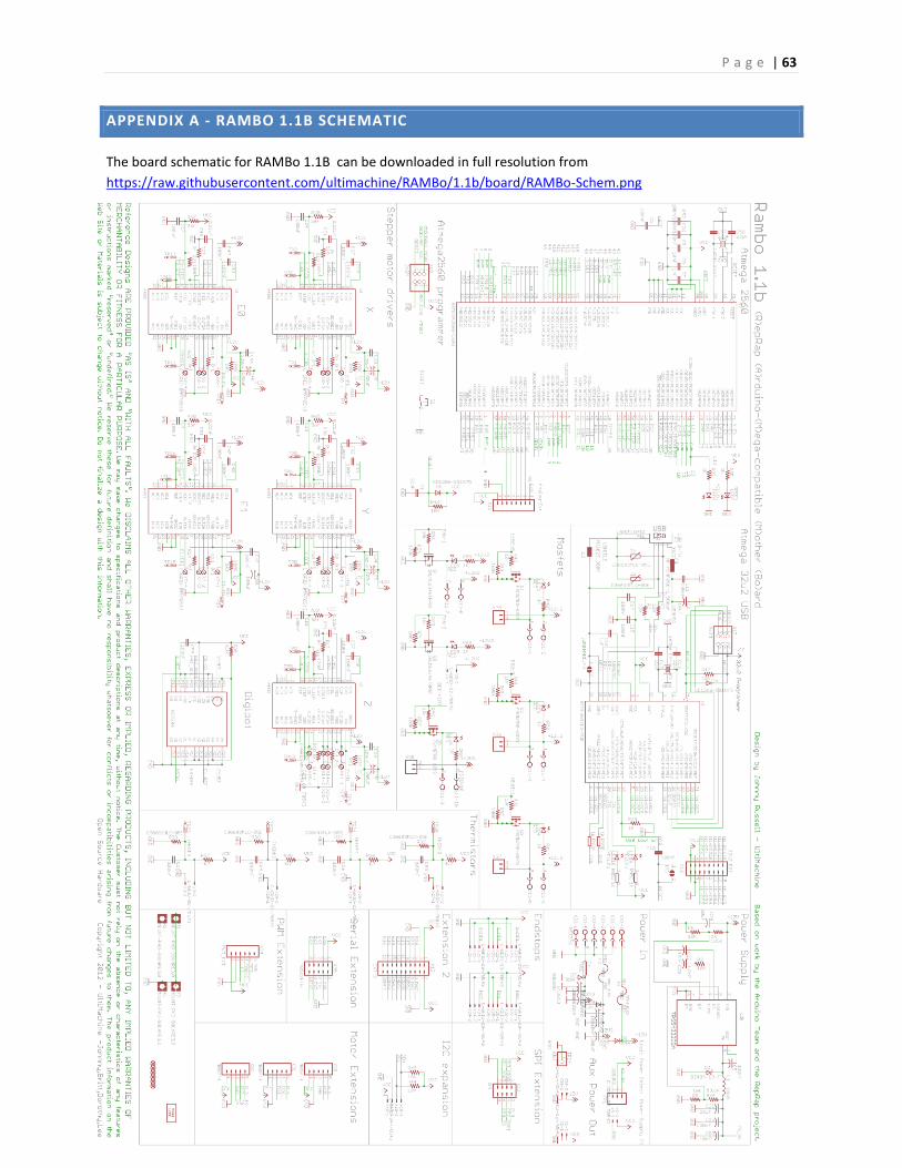
APPENDIX A - RAMBO 1.1B SCHEMATIC
The board schematic for RAMBo 1.1B can be downloaded in full resolution from
https://raw.githubusercontent.com/ultimachine/RAMBo/1.1b/board/RAMBo-Schem.png
P a g e | 64
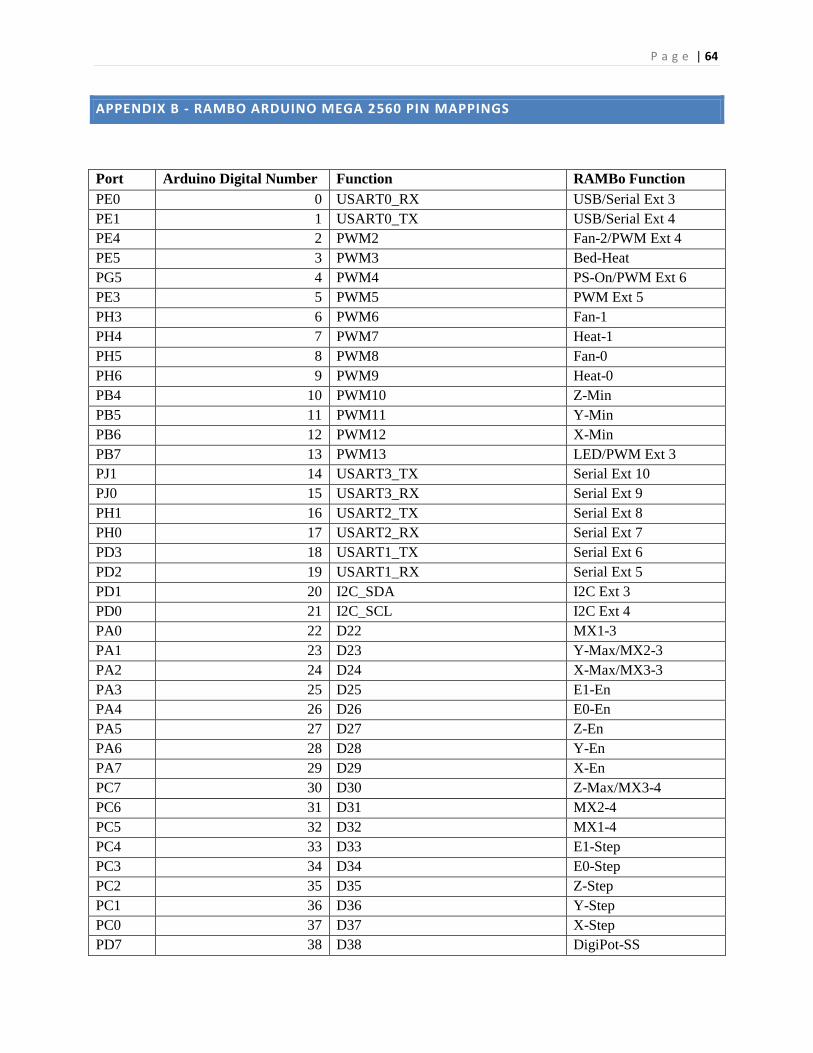
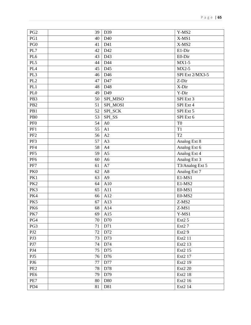
APPENDIX B - RAMBO ARDUINO MEGA 2560 PIN MAPPINGS
Port Arduino Digital Number Function RAMBo Function
PE0 0 USART0_RX USB/Serial Ext 3
PE1 1 USART0_TX USB/Serial Ext 4
PE4 2 PWM2 Fan-2/PWM Ext 4
PE5 3 PWM3 Bed-Heat
PG5 4 PWM4 PS-On/PWM Ext 6
PE3 5 PWM5 PWM Ext 5
PH3 6 PWM6 Fan-1
PH4 7 PWM7 Heat-1
PH5 8 PWM8 Fan-0
PH6 9 PWM9 Heat-0
PB4 10 PWM10 Z-Min
PB5 11 PWM11 Y-Min
PB6 12 PWM12 X-Min
PB7 13 PWM13 LED/PWM Ext 3
PJ1 14 USART3_TX Serial Ext 10
PJ0 15 USART3_RX Serial Ext 9
PH1 16 USART2_TX Serial Ext 8
PH0 17 USART2_RX Serial Ext 7
PD3 18 USART1_TX Serial Ext 6
PD2 19 USART1_RX Serial Ext 5
PD1 20 I2C_SDA I2C Ext 3
PD0 21 I2C_SCL I2C Ext 4
PA0 22 D22 MX1-3
PA1 23 D23 Y-Max/MX2-3
PA2 24 D24 X-Max/MX3-3
PA3 25 D25 E1-En
PA4 26 D26 E0-En
PA5 27 D27 Z-En
PA6 28 D28 Y-En
PA7 29 D29 X-En
PC7 30 D30 Z-Max/MX3-4
PC6 31 D31 MX2-4
PC5 32 D32 MX1-4
PC4 33 D33 E1-Step
PC3 34 D34 E0-Step
PC2 35 D35 Z-Step
PC1 36 D36 Y-Step
PC0 37 D37 X-Step
PD7 38 D38 DigiPot-SS
P a g e | 65
PG2 39 D39 Y-MS2
PG1 40 D40 X-MS1
PG0 41 D41 X-MS2
PL7 42 D42 E1-Dir
PL6 43 D43 E0-Dir
PL5 44 D44 MX1-5
PL4 45 D45 MX2-5
PL3 46 D46 SPI Ext 2/MX3-5
PL2 47 D47 Z-Dir
PL1 48 D48 X-Dir
PL0 49 D49 Y-Dir
PB3 50 SPI_MISO SPI Ext 3
PB2 51 SPI_MOSI SPI Ext 4
PB1 52 SPI_SCK SPI Ext 5
PB0 53 SPI_SS SPI Ext 6
PF0 54 A0 T0
PF1 55 A1 T1
PF2 56 A2 T2
PF3 57 A3 Analog Ext 8
PF4 58 A4 Analog Ext 6
PF5 59 A5 Analog Ext 4
PF6 60 A6 Analog Ext 3
PF7 61 A7 T3/Analog Ext 5
PK0 62 A8 Analog Ext 7
PK1 63 A9 E1-MS1
PK2 64 A10 E1-MS2
PK3 65 A11 E0-MS1
PK4 66 A12 E0-MS2
PK5 67 A13 Z-MS2
PK6 68 A14 Z-MS1
PK7 69 A15 Y-MS1
PG4 70 D70 Ext2 5
PG3 71 D71 Ext2 7
PJ2 72 D72 Ext2 9
PJ3 73 D73 Ext2 11
PJ7 74 D74 Ext2 13
PJ4 75 D75 Ext2 15
PJ5 76 D76 Ext2 17
PJ6 77 D77 Ext2 19
PE2 78 D78 Ext2 20
PE6 79 D79 Ext2 18
PE7 80 D80 Ext2 16
PD4 81 D81 Ext2 14

P a g e | 66
PD5 82 D82 Ext2 12
PD6 83 D83 Ext2 10
PH2 84 D84 Ext2 8
PH7 85 D85 Ext2 6
P a g e | 67
APPENDIX C - GNU FREE DOCUMENTATION LICENSE
Version 1.3, 3 November 2008
Copyright © 2000, 2001, 2002, 2007, 2008 Free Software Foundation, Inc. <http://fsf.org/>
Everyone is permitted to copy and distribute verbatim copies of this license document, but changing it is not al-
lowed.
0. PREAMBLE
The purpose of this License is to make a manual, textbook, or other functional and useful document "free" in the
sense of freedom: to assure everyone the effective freedom to copy and redistribute it, with or without modifying
it, either commercially or noncommercially. Secondarily, this License preserves for the author and publisher a way
to get credit for their work, while not being considered responsible for modifications made by others.
This License is a kind of "copyleft", which means that derivative works of the document must themselves be free in
the same sense. It complements the GNU General Public License, which is a copyleft license designed for free
software.
We have designed this License in order to use it for manuals for free software, because free software needs free
documentation: a free program should come with manuals providing the same freedoms that the software does.
But this License is not limited to software manuals; it can be used for any textual work, regardless of subject mat-
ter or whether it is published as a printed book. We recommend this License principally for works whose purpose
is instruction or reference.
1. APPLICABILITY AND DEFINITIONS
This License applies to any manual or other work, in any medium, that contains a notice placed by the copyright
holder saying it can be distributed under the terms of this License. Such a notice grants a world-wide, royalty-free
license, unlimited in duration, to use that work under the conditions stated herein. The "Document", below, refers
to any such manual or work. Any member of the public is a licensee, and is addressed as "you". You accept the
license if you copy, modify or distribute the work in a way requiring permission under copyright law.

P a g e | 68
A "Modified Version" of the Document means any work containing the Document or a portion of it, either copied
verbatim, or with modifications and/or translated into another language.
A "Secondary Section" is a named appendix or a front-matter section of the Document that deals exclusively with
the relationship of the publishers or authors of the Document to the Document's overall subject (or to related mat-
ters) and contains nothing that could fall directly within that overall subject. (Thus, if the Document is in part a
textbook of mathematics, a Secondary Section may not explain any mathematics.) The relationship could be a mat-
ter of historical connection with the subject or with related matters, or of legal, commercial, philosophical, ethical
or political position regarding them.
The "Invariant Sections" are certain Secondary Sections whose titles are designated, as being those of Invariant
Sections, in the notice that says that the Document is released under this License. If a section does not fit the
above definition of Secondary then it is not allowed to be designated as Invariant. The Document may contain zero
Invariant Sections. If the Document does not identify any Invariant Sections then there are none.
The "Cover Texts" are certain short passages of text that are listed, as Front-Cover Texts or Back-Cover Texts, in the
notice that says that the Document is released under this License. A Front-Cover Text may be at most 5 words, and
a Back-Cover Text may be at most 25 words.
A "Transparent" copy of the Document means a machine-readable copy, represented in a format whose specifica-
tion is available to the general public, that is suitable for revising the document straightforwardly with generic text
editors or (for images composed of pixels) generic paint programs or (for drawings) some widely available drawing
editor, and that is suitable for input to text formatters or for automatic translation to a variety of formats suitable
for input to text formatters. A copy made in an otherwise Transparent file format whose markup, or absence of
markup, has been arranged to thwart or discourage subsequent modification by readers is not Transparent. An
image format is not Transparent if used for any substantial amount of text. A copy that is not "Transparent" is
called "Opaque".
Examples of suitable formats for Transparent copies include plain ASCII without markup, Texinfo input format, La-
TeX input format, SGML or XML using a publicly available DTD, and standard-conforming simple HTML, PostScript
or PDF designed for human modification. Examples of transparent image formats include PNG, XCF and JPG.
Opaque formats include proprietary formats that can be read and edited only by proprietary word processors,
SGML or XML for which the DTD and/or processing tools are not generally available, and the machine-generated
HTML, PostScript or PDF produced by some word processors for output purposes only.
The "Title Page" means, for a printed book, the title page itself, plus such following pages as are needed to hold,
legibly, the material this License requires to appear in the title page. For works in formats which do not have any
P a g e | 69
title page as such, "Title Page" means the text near the most prominent appearance of the work's title, preceding
the beginning of the body of the text.
The "publisher" means any person or entity that distributes copies of the Document to the public.
A section "Entitled XYZ" means a named subunit of the Document whose title either is precisely XYZ or contains
XYZ in parentheses following text that translates XYZ in another language. (Here XYZ stands for a specific section
name mentioned below, such as "Acknowledgements", "Dedications", "Endorsements", or "History".) To "Preserve
the Title" of such a section when you modify the Document means that it remains a section "Entitled XYZ" accord-
ing to this definition.
The Document may include Warranty Disclaimers next to the notice which states that this License applies to the
Document. These Warranty Disclaimers are considered to be included by reference in this License, but only as re-
gards disclaiming warranties: any other implication that these Warranty Disclaimers may have is void and has no
effect on the meaning of this License.
2. VERBATIM COPYING
You may copy and distribute the Document in any medium, either commercially or noncommercially, provided
that this License, the copyright notices, and the license notice saying this License applies to the Document are re-
produced in all copies, and that you add no other conditions whatsoever to those of this License. You may not use
technical measures to obstruct or control the reading or further copying of the copies you make or distribute.
However, you may accept compensation in exchange for copies. If you distribute a large enough number of copies
you must also follow the conditions in section 3.
You may also lend copies, under the same conditions stated above, and you may publicly display copies.
3. COPYING IN QUANTITY
If you publish printed copies (or copies in media that commonly have printed covers) of the Document, numbering
more than 100, and the Document's license notice requires Cover Texts, you must enclose the copies in covers that
carry, clearly and legibly, all these Cover Texts: Front-Cover Texts on the front cover, and Back-Cover Texts on the
back cover. Both covers must also clearly and legibly identify you as the publisher of these copies. The front cover
must present the full title with all words of the title equally prominent and visible. You may add other material on
the covers in addition. Copying with changes limited to the covers, as long as they preserve the title of the Docu-
ment and satisfy these conditions, can be treated as verbatim copying in other respects.

P a g e | 70
If the required texts for either cover are too voluminous to fit legibly, you should put the first ones listed (as many
as fit reasonably) on the actual cover, and continue the rest onto adjacent pages.
If you publish or distribute Opaque copies of the Document numbering more than 100, you must either include a
machine-readable Transparent copy along with each Opaque copy, or state in or with each Opaque copy a com-
puter-network location from which the general network-using public has access to download using public-standard
network protocols a complete Transparent copy of the Document, free of added material. If you use the latter op-
tion, you must take reasonably prudent steps, when you begin distribution of Opaque copies in quantity, to ensure
that this Transparent copy will remain thus accessible at the stated location until at least one year after the last
time you distribute an Opaque copy (directly or through your agents or retailers) of that edition to the public.
It is requested, but not required, that you contact the authors of the Document well before redistributing any large
number of copies, to give them a chance to provide you with an updated version of the Document.
4. MODIFICATIONS
You may copy and distribute a Modified Version of the Document under the conditions of sections 2 and 3 above,
provided that you release the Modified Version under precisely this License, with the Modified Version filling the
role of the Document, thus licensing distribution and modification of the Modified Version to whoever possesses a
copy of it. In addition, you must do these things in the Modified Version:
A. Use in the Title Page (and on the covers, if any) a title distinct from that of the Document, and from those of
previous versions (which should, if there were any, be listed in the History section of the Document). You may use
the same title as a previous version if the original publisher of that version gives permission.
B. List on the Title Page, as authors, one or more persons or entities responsible for authorship of the modifica-
tions in the Modified Version, together with at least five of the principal authors of the Document (all of its princi-
pal authors, if it has fewer than five), unless they release you from this requirement.
C. State on the Title page the name of the publisher of the Modified Version, as the publisher.
D. Preserve all the copyright notices of the Document.
E. Add an appropriate copyright notice for your modifications adjacent to the other copyright notices.
F. Include, immediately after the copyright notices, a license notice giving the public permission to use the Modi-
fied Version under the terms of this License, in the form shown in the Addendum below.
G. Preserve in that license notice the full lists of Invariant Sections and required Cover Texts given in the Docu-
ment's license notice.
H. Include an unaltered copy of this License.
P a g e | 71
I. Preserve the section Entitled "History", Preserve its Title, and add to it an item stating at least the title, year, new
authors, and publisher of the Modified Version as given on the Title Page. If there is no section Entitled "History" in
the Document, create one stating the title, year, authors, and publisher of the Document as given on its Title Page,
then add an item describing the Modified Version as stated in the previous sentence.
J. Preserve the network location, if any, given in the Document for public access to a Transparent copy of the Doc-
ument, and likewise the network locations given in the Document for previous versions it was based on. These may
be placed in the "History" section. You may omit a network location for a work that was published at least four
years before the Document itself, or if the original publisher of the version it refers to gives permission.
K. For any section Entitled "Acknowledgements" or "Dedications", Preserve the Title of the section, and preserve in
the section all the substance and tone of each of the contributor acknowledgements and/or dedications given
therein.
L. Preserve all the Invariant Sections of the Document, unaltered in their text and in their titles. Section numbers or
the equivalent are not considered part of the section titles.
M. Delete any section Entitled "Endorsements". Such a section may not be included in the Modified Version.
N. Do not retitle any existing section to be Entitled "Endorsements" or to conflict in title with any Invariant Section.
O. Preserve any Warranty Disclaimers.
If the Modified Version includes new front-matter sections or appendices that qualify as Secondary Sections and
contain no material copied from the Document, you may at your option designate some or all of these sections as
invariant. To do this, add their titles to the list of Invariant Sections in the Modified Version's license notice. These
titles must be distinct from any other section titles.
You may add a section Entitled "Endorsements", provided it contains nothing but endorsements of your Modified
Version by various parties—for example, statements of peer review or that the text has been approved by an or-
ganization as the authoritative definition of a standard.
You may add a passage of up to five words as a Front-Cover Text, and a passage of up to 25 words as a Back-Cover
Text, to the end of the list of Cover Texts in the Modified Version. Only one passage of Front-Cover Text and one of
Back-Cover Text may be added by (or through arrangements made by) any one entity. If the Document already
includes a cover text for the same cover, previously added by you or by arrangement made by the same entity you
are acting on behalf of, you may not add another; but you may replace the old one, on explicit permission from the
previous publisher that added the old one.
The author(s) and publisher(s) of the Document do not by this License give permission to use their names for pub-
licity for or to assert or imply endorsement of any Modified Version.
P a g e | 72
5. COMBINING DOCUMENTS
You may combine the Document with other documents released under this License, under the terms defined in
section 4 above for modified versions, provided that you include in the combination all of the Invariant Sections of
all of the original documents, unmodified, and list them all as Invariant Sections of your combined work in its li-
cense notice, and that you preserve all their Warranty Disclaimers.
The combined work need only contain one copy of this License, and multiple identical Invariant Sections may be
replaced with a single copy. If there are multiple Invariant Sections with the same name but different contents,
make the title of each such section unique by adding at the end of it, in parentheses, the name of the original au-
thor or publisher of that section if known, or else a unique number. Make the same adjustment to the section ti-
tles in the list of Invariant Sections in the license notice of the combined work.
In the combination, you must combine any sections Entitled "History" in the various original documents, forming
one section Entitled "History"; likewise combine any sections Entitled "Acknowledgements", and any sections Enti-
tled "Dedications". You must delete all sections Entitled "Endorsements".
6. COLLECTIONS OF DOCUMENTS
You may make a collection consisting of the Document and other documents released under this License, and re-
place the individual copies of this License in the various documents with a single copy that is included in the collec-
tion, provided that you follow the rules of this License for verbatim copying of each of the documents in all other
respects.
You may extract a single document from such a collection, and distribute it individually under this License, provid-
ed you insert a copy of this License into the extracted document, and follow this License in all other respects re-
garding verbatim copying of that document.
7. AGGREGATION WITH INDEPENDENT WORKS
A compilation of the Document or its derivatives with other separate and independent documents or works, in or
on a volume of a storage or distribution medium, is called an "aggregate" if the copyright resulting from the compi-
lation is not used to limit the legal rights of the compilation's users beyond what the individual works permit.
When the Document is included in an aggregate, this License does not apply to the other works in the aggregate
which are not themselves derivative works of the Document.
P a g e | 73
If the Cover Text requirement of section 3 is applicable to these copies of the Document, then if the Document is
less than one half of the entire aggregate, the Document's Cover Texts may be placed on covers that bracket the
Document within the aggregate, or the electronic equivalent of covers if the Document is in electronic form. Oth-
erwise they must appear on printed covers that bracket the whole aggregate.
8. TRANSLATION
Translation is considered a kind of modification, so you may distribute translations of the Document under the
terms of section 4. Replacing Invariant Sections with translations requires special permission from their copyright
holders, but you may include translations of some or all Invariant Sections in addition to the original versions of
these Invariant Sections. You may include a translation of this License, and all the license notices in the Document,
and any Warranty Disclaimers, provided that you also include the original English version of this License and the
original versions of those notices and disclaimers. In case of a disagreement between the translation and the origi-
nal version of this License or a notice or disclaimer, the original version will prevail.
If a section in the Document is Entitled "Acknowledgements", "Dedications", or "History", the requirement (section
4) to Preserve its Title (section 1) will typically require changing the actual title.
9. TERMINATION
You may not copy, modify, sublicense, or distribute the Document except as expressly provided under this License.
Any attempt otherwise to copy, modify, sublicense, or distribute it is void, and will automatically terminate your
rights under this License.
However, if you cease all violation of this License, then your license from a particular copyright holder is reinstated
(a) provisionally, unless and until the copyright holder explicitly and finally terminates your license, and (b) perma-
nently, if the copyright holder fails to notify you of the violation by some reasonable means prior to 60 days after
the cessation.
Moreover, your license from a particular copyright holder is reinstated permanently if the copyright holder notifies
you of the violation by some reasonable means, this is the first time you have received notice of violation of this
License (for any work) from that copyright holder, and you cure the violation prior to 30 days after your receipt of
the notice.
Termination of your rights under this section does not terminate the licenses of parties who have received copies
or rights from you under this License. If your rights have been terminated and not permanently reinstated, receipt
of a copy of some or all of the same material does not give you any rights to use it.
P a g e | 74
10. FUTURE REVISIONS OF THIS LICENSE
The Free Software Foundation may publish new, revised versions of the GNU Free Documentation License from
time to time. Such new versions will be similar in spirit to the present version, but may differ in detail to address
new problems or concerns. See http://www.gnu.org/copyleft/.
Each version of the License is given a distinguishing version number. If the Document specifies that a particular
numbered version of this License "or any later version" applies to it, you have the option of following the terms
and conditions either of that specified version or of any later version that has been published (not as a draft) by
the Free Software Foundation. If the Document does not specify a version number of this License, you may choose
any version ever published (not as a draft) by the Free Software Foundation. If the Document specifies that a proxy
can decide which future versions of this License can be used, that proxy's public statement of acceptance of a ver-
sion permanently authorizes you to choose that version for the Document.
11. RELICENSING
"Massive Multiauthor Collaboration Site" (or "MMC Site") means any World Wide Web server that publishes copy-
rightable works and also provides prominent facilities for anybody to edit those works. A public wiki that anybody
can edit is an example of such a server. A "Massive Multiauthor Collaboration" (or "MMC") contained in the site
means any set of copyrightable works thus published on the MMC site.
"CC-BY-SA" means the Creative Commons Attribution-Share Alike 3.0 license published by Creative Commons Cor-
poration, a not-for-profit corporation with a principal place of business in San Francisco, California, as well as fu-
ture copyleft versions of that license published by that same organization.
"Incorporate" means to publish or republish a Document, in whole or in part, as part of another Document.
An MMC is "eligible for relicensing" if it is licensed under this License, and if all works that were first published un-
der this License somewhere other than this MMC, and subsequently incorporated in whole or in part into the
MMC, (1) had no cover texts or invariant sections, and (2) were thus incorporated prior to November 1, 2008.
The operator of an MMC Site may republish an MMC contained in the site under CC-BY-SA on the same site at any
time before August 1, 2009, provided the MMC is eligible for relicensing.

P a g e | 75
APPENDIX D - CREATIVE COMMONS ATTRIBUTION-SHAREALIKE 3.0 UNPORTED
License
THE WORK (AS DEFINED BELOW) IS PROVIDED UNDER THE TERMS OF THIS CREATIVE COMMONS PUBLIC LICENSE
("CCPL" OR "LICENSE"). THE WORK IS PROTECTED BY COPYRIGHT AND/OR OTHER APPLICABLE LAW. ANY USE OF
THE WORK OTHER THAN AS AUTHORIZED UNDER THIS LICENSE OR COPYRIGHT LAW IS PROHIBITED.
BY EXERCISING ANY RIGHTS TO THE WORK PROVIDED HERE, YOU ACCEPT AND AGREE TO BE BOUND BY THE
TERMS OF THIS LICENSE. TO THE EXTENT THIS LICENSE MAY BE CONSIDERED TO BE A CONTRACT, THE LICENSOR
GRANTS YOU THE RIGHTS CONTAINED HERE IN CONSIDERATION OF YOUR ACCEPTANCE OF SUCH TERMS AND
CONDITIONS.
1. DEFINITIONS
"Adaptation" means a work based upon the Work, or upon the Work and other pre-existing works, such as a trans-
lation, adaptation, derivative work, arrangement of music or other alterations of a literary or artistic work, or pho-
nogram or performance and includes cinematographic adaptations or any other form in which the Work may be
recast, transformed, or adapted including in any form recognizably derived from the original, except that a work
that constitutes a Collection will not be considered an Adaptation for the purpose of this License. For the avoid-
ance of doubt, where the Work is a musical work, performance or phonogram, the synchronization of the Work in
timed-relation with a moving image ("synching") will be considered an Adaptation for the purpose of this License.
"Collection" means a collection of literary or artistic works, such as encyclopedias and anthologies, or performanc-
es, phonograms or broadcasts, or other works or subject matter other than works listed in Section 1(f) below,
which, by reason of the selection and arrangement of their contents, constitute intellectual creations, in which the
Work is included in its entirety in unmodified form along with one or more other contributions, each constituting
separate and independent works in themselves, which together are assembled into a collective whole. A work that
constitutes a Collection will not be considered an Adaptation (as defined below) for the purposes of this License.
"Creative Commons Compatible License" means a license that is listed at
http://creativecommons.org/compatiblelicenses that has been approved by Creative Commons as being essential-
ly equivalent to this License, including, at a minimum, because that license: (i) contains terms that have the same
purpose, meaning and effect as the License Elements of this License; and, (ii) explicitly permits the relicensing of
adaptations of works made available under that license under this License or a Creative Commons jurisdiction li-
cense with the same License Elements as this License.
"Distribute" means to make available to the public the original and copies of the Work or Adaptation, as appropri-
ate, through sale or other transfer of ownership.
P a g e | 76
"License Elements" means the following high-level license attributes as selected by Licensor and indicated in the
title of this License: Attribution, ShareAlike.
"Licensor" means the individual, individuals, entity or entities that offer(s) the Work under the terms of this Li-
cense.
"Original Author" means, in the case of a literary or artistic work, the individual, individuals, entity or entities who
created the Work or if no individual or entity can be identified, the publisher; and in addition (i) in the case of a
performance the actors, singers, musicians, dancers, and other persons who act, sing, deliver, declaim, play in,
interpret or otherwise perform literary or artistic works or expressions of folklore; (ii) in the case of a phonogram
the producer being the person or legal entity who first fixes the sounds of a performance or other sounds; and, (iii)
in the case of broadcasts, the organization that transmits the broadcast.
"Work" means the literary and/or artistic work offered under the terms of this License including without limitation
any production in the literary, scientific and artistic domain, whatever may be the mode or form of its expression
including digital form, such as a book, pamphlet and other writing; a lecture, address, sermon or other work of the
same nature; a dramatic or dramatico-musical work; a choreographic work or entertainment in dumb show; a mu-
sical composition with or without words; a cinematographic work to which are assimilated works expressed by a
process analogous to cinematography; a work of drawing, painting, architecture, sculpture, engraving or lithogra-
phy; a photographic work to which are assimilated works expressed by a process analogous to photography; a
work of applied art; an illustration, map, plan, sketch or three-dimensional work relative to geography, topogra-
phy, architecture or science; a performance; a broadcast; a phonogram; a compilation of data to the extent it is
protected as a copyrightable work; or a work performed by a variety or circus performer to the extent it is not oth-
erwise considered a literary or artistic work.
"You" means an individual or entity exercising rights under this License who has not previously violated the terms
of this License with respect to the Work, or who has received express permission from the Licensor to exercise
rights under this License despite a previous violation.
"Publicly Perform" means to perform public recitations of the Work and to communicate to the public those public
recitations, by any means or process, including by wire or wireless means or public digital performances; to make
available to the public Works in such a way that members of the public may access these Works from a place and
at a place individually chosen by them; to perform the Work to the public by any means or process and the com-
munication to the public of the performances of the Work, including by public digital performance; to broadcast
and rebroadcast the Work by any means including signs, sounds or images.
"Reproduce" means to make copies of the Work by any means including without limitation by sound or visual re-
cordings and the right of fixation and reproducing fixations of the Work, including storage of a protected perfor-
mance or phonogram in digital form or other electronic medium.
2. FAIR DEALING RIGHTS.
Nothing in this License is intended to reduce, limit, or restrict any uses free from copyright or rights arising from
limitations or exceptions that are provided for in connection with the copyright protection under copyright law or
other applicable laws.

P a g e | 77
3. LICENSE GRANT.
Subject to the terms and conditions of this License, Licensor hereby grants You a worldwide, royalty-free, non-
exclusive, perpetual (for the duration of the applicable copyright) license to exercise the rights in the Work as stat-
ed below:
to Reproduce the Work, to incorporate the Work into one or more Collections, and to Reproduce the Work as in-
corporated in the Collections;
to create and Reproduce Adaptations provided that any such Adaptation, including any translation in any medium,
takes reasonable steps to clearly label, demarcate or otherwise identify that changes were made to the original
Work. For example, a translation could be marked "The original work was translated from English to Spanish," or a
modification could indicate "The original work has been modified.";
to Distribute and Publicly Perform the Work including as incorporated in Collections; and,
to Distribute and Publicly Perform Adaptations.
For the avoidance of doubt:
Non-waivable Compulsory License Schemes. In those jurisdictions in which the right to collect royalties through
any statutory or compulsory licensing scheme cannot be waived, the Licensor reserves the exclusive right to collect
such royalties for any exercise by You of the rights granted under this License;
Waivable Compulsory License Schemes. In those jurisdictions in which the right to collect royalties through any
statutory or compulsory licensing scheme can be waived, the Licensor waives the exclusive right to collect such
royalties for any exercise by You of the rights granted under this License; and,
Voluntary License Schemes. The Licensor waives the right to collect royalties, whether individually or, in the event
that the Licensor is a member of a collecting society that administers voluntary licensing schemes, via that society,
from any exercise by You of the rights granted under this License.
The above rights may be exercised in all media and formats whether now known or hereafter devised. The above
rights include the right to make such modifications as are technically necessary to exercise the rights in other me-
dia and formats. Subject to Section 8(f), all rights not expressly granted by Licensor are hereby reserved.
4. RESTRICTIONS.
The license granted in Section 3 above is expressly made subject to and limited by the following restrictions:
P a g e | 78
You may Distribute or Publicly Perform the Work only under the terms of this License. You must include a copy of,
or the Uniform Resource Identifier (URI) for, this License with every copy of the Work You Distribute or Publicly
Perform. You may not offer or impose any terms on the Work that restrict the terms of this License or the ability of
the recipient of the Work to exercise the rights granted to that recipient under the terms of the License. You may
not sublicense the Work. You must keep intact all notices that refer to this License and to the disclaimer of warran-
ties with every copy of the Work You Distribute or Publicly Perform. When You Distribute or Publicly Perform the
Work, You may not impose any effective technological measures on the Work that restrict the ability of a recipient
of the Work from You to exercise the rights granted to that recipient under the terms of the License. This Section
4(a) applies to the Work as incorporated in a Collection, but this does not require the Collection apart from the
Work itself to be made subject to the terms of this License. If You create a Collection, upon notice from any Licen-
sor You must, to the extent practicable, remove from the Collection any credit as required by Section 4(c), as re-
quested. If You create an Adaptation, upon notice from any Licensor You must, to the extent practicable, remove
from the Adaptation any credit as required by Section 4(c), as requested.
You may Distribute or Publicly Perform an Adaptation only under the terms of: (i) this License; (ii) a later version of
this License with the same License Elements as this License; (iii) a Creative Commons jurisdiction license (either this
or a later license version) that contains the same License Elements as this License (e.g., Attribution-ShareAlike 3.0
US)); (iv) a Creative Commons Compatible License. If you license the Adaptation under one of the licenses men-
tioned in (iv), you must comply with the terms of that license. If you license the Adaptation under the terms of any
of the licenses mentioned in (i), (ii) or (iii) (the "Applicable License"), you must comply with the terms of the Appli-
cable License generally and the following provisions: (I) You must include a copy of, or the URI for, the Applicable
License with every copy of each Adaptation You Distribute or Publicly Perform; (II) You may not offer or impose
any terms on the Adaptation that restrict the terms of the Applicable License or the ability of the recipient of the
Adaptation to exercise the rights granted to that recipient under the terms of the Applicable License; (III) You must
keep intact all notices that refer to the Applicable License and to the disclaimer of warranties with every copy of
the Work as included in the Adaptation You Distribute or Publicly Perform; (IV) when You Distribute or Publicly
Perform the Adaptation, You may not impose any effective technological measures on the Adaptation that restrict
the ability of a recipient of the Adaptation from You to exercise the rights granted to that recipient under the
terms of the Applicable License. This Section 4(b) applies to the Adaptation as incorporated in a Collection, but this
does not require the Collection apart from the Adaptation itself to be made subject to the terms of the Applicable
License.
If You Distribute, or Publicly Perform the Work or any Adaptations or Collections, You must, unless a request has
been made pursuant to Section 4(a), keep intact all copyright notices for the Work and provide, reasonable to the
medium or means You are utilizing: (i) the name of the Original Author (or pseudonym, if applicable) if supplied,
and/or if the Original Author and/or Licensor designate another party or parties (e.g., a sponsor institute, publish-
ing entity, journal) for attribution ("Attribution Parties") in Licensor's copyright notice, terms of service or by other
reasonable means, the name of such party or parties; (ii) the title of the Work if supplied; (iii) to the extent reason-
ably practicable, the URI, if any, that Licensor specifies to be associated with the Work, unless such URI does not
refer to the copyright notice or licensing information for the Work; and (iv) , consistent with Ssection 3(b), in the
case of an Adaptation, a credit identifying the use of the Work in the Adaptation (e.g., "French translation of the
Work by Original Author," or "Screenplay based on original Work by Original Author"). The credit required by this
Section 4(c) may be implemented in any reasonable manner; provided, however, that in the case of a Adaptation
or Collection, at a minimum such credit will appear, if a credit for all contributing authors of the Adaptation or Col-
lection appears, then as part of these credits and in a manner at least as prominent as the credits for the other
contributing authors. For the avoidance of doubt, You may only use the credit required by this Section for the pur-

P a g e | 79
pose of attribution in the manner set out above and, by exercising Your rights under this License, You may not im-
plicitly or explicitly assert or imply any connection with, sponsorship or endorsement by the Original Author, Licen-
sor and/or Attribution Parties, as appropriate, of You or Your use of the Work, without the separate, express prior
written permission of the Original Author, Licensor and/or Attribution Parties.
Except as otherwise agreed in writing by the Licensor or as may be otherwise permitted by applicable law, if You
Reproduce, Distribute or Publicly Perform the Work either by itself or as part of any Adaptations or Collections,
You must not distort, mutilate, modify or take other derogatory action in relation to the Work which would be
prejudicial to the Original Author's honor or reputation. Licensor agrees that in those jurisdictions (e.g. Japan), in
which any exercise of the right granted in Section 3(b) of this License (the right to make Adaptations) would be
deemed to be a distortion, mutilation, modification or other derogatory action prejudicial to the Original Author's
honor and reputation, the Licensor will waive or not assert, as appropriate, this Section, to the fullest extent per-
mitted by the applicable national law, to enable You to reasonably exercise Your right under Section 3(b) of this
License (right to make Adaptations) but not otherwise.
5. REPRESENTATIONS, WARRANTIES AND DISCLAIMER
UNLESS OTHERWISE MUTUALLY AGREED TO BY THE PARTIES IN WRITING, LICENSOR OFFERS THE WORK AS-IS AND
MAKES NO REPRESENTATIONS OR WARRANTIES OF ANY KIND CONCERNING THE WORK, EXPRESS, IMPLIED, STAT-
UTORY OR OTHERWISE, INCLUDING, WITHOUT LIMITATION, WARRANTIES OF TITLE, MERCHANTIBILITY, FITNESS
FOR A PARTICULAR PURPOSE, NONINFRINGEMENT, OR THE ABSENCE OF LATENT OR OTHER DEFECTS, ACCURACY,
OR THE PRESENCE OF ABSENCE OF ERRORS, WHETHER OR NOT DISCOVERABLE. SOME JURISDICTIONS DO NOT
ALLOW THE EXCLUSION OF IMPLIED WARRANTIES, SO SUCH EXCLUSION MAY NOT APPLY TO YOU.
6. LIMITATION ON LIABILITY.
EXCEPT TO THE EXTENT REQUIRED BY APPLICABLE LAW, IN NO EVENT WILL LICENSOR BE LIABLE TO YOU ON ANY
LEGAL THEORY FOR ANY SPECIAL, INCIDENTAL, CONSEQUENTIAL, PUNITIVE OR EXEMPLARY DAMAGES ARISING
OUT OF THIS LICENSE OR THE USE OF THE WORK, EVEN IF LICENSOR HAS BEEN ADVISED OF THE POSSIBILITY OF
SUCH DAMAGES.
7. TERMINATION
This License and the rights granted hereunder will terminate automatically upon any breach by You of the terms of
this License. Individuals or entities who have received Adaptations or Collections from You under this License,
however, will not have their licenses terminated provided such individuals or entities remain in full compliance
with those licenses. Sections 1, 2, 5, 6, 7, and 8 will survive any termination of this License.
P a g e | 80
Subject to the above terms and conditions, the license granted here is perpetual (for the duration of the applicable
copyright in the Work). Notwithstanding the above, Licensor reserves the right to release the Work under different
license terms or to stop distributing the Work at any time; provided, however that any such election will not serve
to withdraw this License (or any other license that has been, or is required to be, granted under the terms of this
License), and this License will continue in full force and effect unless terminated as stated above.
8. MISCELLANEOUS
Each time You Distribute or Publicly Perform the Work or a Collection, the Licensor offers to the recipient a license
to the Work on the same terms and conditions as the license granted to You under this License.
Each time You Distribute or Publicly Perform an Adaptation, Licensor offers to the recipient a license to the original
Work on the same terms and conditions as the license granted to You under this License.
If any provision of this License is invalid or unenforceable under applicable law, it shall not affect the validity or
enforceability of the remainder of the terms of this License, and without further action by the parties to this
agreement, such provision shall be reformed to the minimum extent necessary to make such provision valid and
enforceable.
No term or provision of this License shall be deemed waived and no breach consented to unless such waiver or
consent shall be in writing and signed by the party to be charged with such waiver or consent.
This License constitutes the entire agreement between the parties with respect to the Work licensed here. There
are no understandings, agreements or representations with respect to the Work not specified here. Licensor shall
not be bound by any additional provisions that may appear in any communication from You. This License may not
be modified without the mutual written agreement of the Licensor and You.
The rights granted under, and the subject matter referenced, in this License were drafted utilizing the terminology
of the Berne Convention for the Protection of Literary and Artistic Works (as amended on September 28, 1979),
the Rome Convention of 1961, the WIPO Copyright Treaty of 1996, the WIPO Performances and Phonograms Trea-
ty of 1996 and the Universal Copyright Convention (as revised on July 24, 1971). These rights and subject matter
take effect in the relevant jurisdiction in which the License terms are sought to be enforced according to the corre-
sponding provisions of the implementation of those treaty provisions in the applicable national law. If the standard
suite of rights granted under applicable copyright law includes additional rights not granted under this License,
such additional rights are deemed to be included in the License; this License is not intended to restrict the license
of any rights under applicable law.