ranvir amol sit lowsize
TRANSCRIPT

1
[20
11
BIN
00
1] R
an
vir D
esa
i [2
01
1B
IN0
44
] Am
ol D
ud
ha
te
Industrial Training

2
[20
11
BIN
00
1] R
an
vir D
esa
i [2
01
1B
IN0
44
] Am
ol D
ud
ha
te
Industrial Training

Letter from the department for training, along with the list of
topics for the training
3
[20
11
BIN
00
1] R
an
vir D
esa
i [2
01
1B
IN0
44
] Am
ol D
ud
ha
te
Industrial Training

Introduction to Thermax, Ltd.
4
[20
11
BIN
00
1] R
an
vir D
esa
i [2
01
1B
IN0
44
] Am
ol D
ud
ha
te
Industrial Training
1. Industry: Energy and Environmental Engineering
2. Products: Vapor Absorption Machines, Boilers, Water Treatment
Plants, Solar Based Cooling, etc
3. Founded: 1980 in Dadar, Mumbai
4. Divisions: C&H, B&H, Power, Enviro, Chemical & Water, Solar energy
5. Headquarters: Pune, India
Training at Thermax Energy House, Chinchwad MIDC in Solid Fuels
section of B&H division
5
[20
11
BIN
00
1] R
an
vir D
esa
i [2
01
1B
IN0
44
] Am
ol D
ud
ha
te
Industrial Training

P&ID
6
[20
11
BIN
00
1] R
an
vir D
esa
i [2
01
1B
IN0
44
] Am
ol D
ud
ha
te
Industrial Training
1. Piping and instrumentation diagrams are the schematic used in the
field of instrumentation and control or automation
2. P&IDs are used by field technicians, engineers, and operators to
better understand the process and how the instrumentation is
interconnected
3. P&IDs use symbol and circles to represent each instrument and how
they are inter-connected in the process

Instrument Tags
7
[20
11
BIN
00
1] R
an
vir D
esa
i [2
01
1B
IN0
44
] Am
ol D
ud
ha
te
Industrial Training
1. Tags are the letters and numbers placed within or near the
instrument to identify the type and function of the device
2. First letter is used to designate the measured variable such as
Pressure, Temperature, Level, Flow, Vibration, etc.
3. Succeeding letter(s) are used to designate the function of the
component or to modify the meaning of the first letter such as
Indicator, Recorder, Controller, Transmitter, Measuring Element,
Switch, Alarm, Valve, etc.
4. These letters are used against the standards for P&ID of
Instrumentation Standards Association (ISA S5.1) as shown in figure
1.1

Figure 1.1: ISA S5.1 Identification Letters
8
[20
11
BIN
00
1] R
an
vir D
esa
i [2
01
1B
IN0
44
] Am
ol D
ud
ha
te
Industrial Training

Instrument Location
9
[20
11
BIN
00
1] R
an
vir D
esa
i [2
01
1B
IN0
44
] Am
ol D
ud
ha
te
Industrial Training
1. The horizontal line in the circle indicates the mounting location of
instrument
2. No line: Mounted in the field near the process for monitoring
3. Solid line: Mounted in the control room accessible to the operator
4. Dashed line: Located out of sight not accessible to the operator
5. A circle in a Square: The display of the instrument is in the control
room of DCS
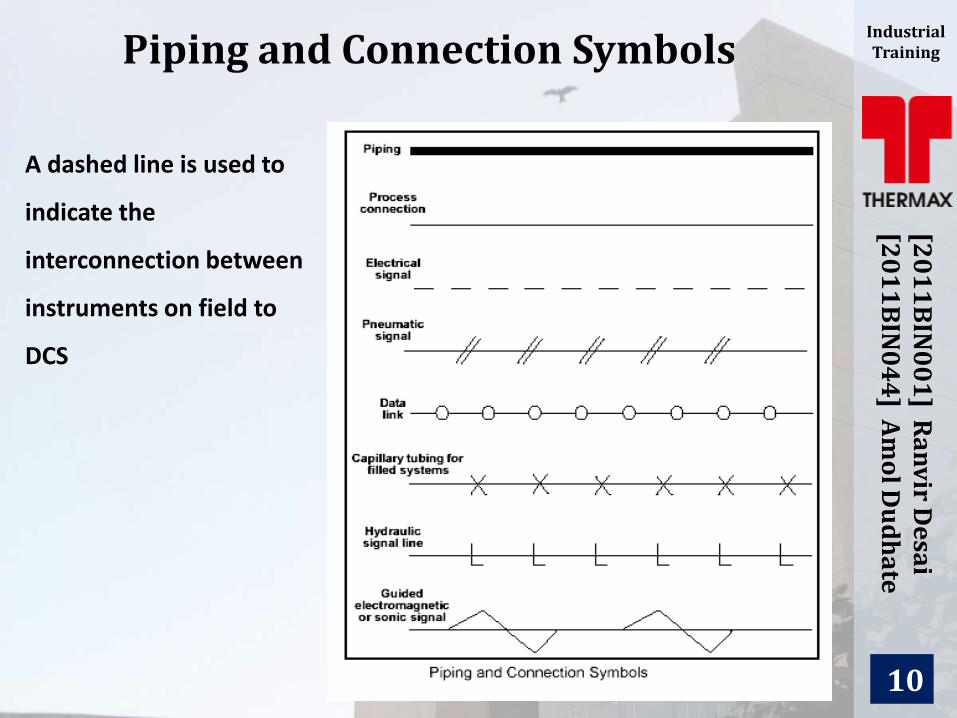
Piping and Connection Symbols
10
[20
11
BIN
00
1] R
an
vir D
esa
i [2
01
1B
IN0
44
] Am
ol D
ud
ha
te
Industrial Training
A dashed line is used to
indicate the
interconnection between
instruments on field to
DCS

Valve Symbols
11
[20
11
BIN
00
1] R
an
vir D
esa
i [2
01
1B
IN0
44
] Am
ol D
ud
ha
te
Industrial Training
1. Valves are used to control the flow of air, water, steam, fuel, gases,
etc.
2. These valves are controlled by either manually by hand or
automatically by electric or pneumatic signals from DCS/PLC
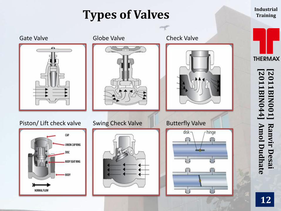
Types of Valves
12
[20
11
BIN
00
1] R
an
vir D
esa
i [2
01
1B
IN0
44
] Am
ol D
ud
ha
te
Industrial Training
Gate Valve Globe Valve Check Valve
Piston/ Lift check valve Swing Check Valve Butterfly Valve
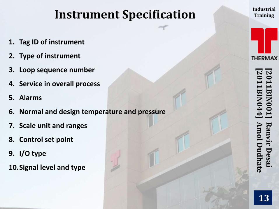
Instrument Specification
13
[20
11
BIN
00
1] R
an
vir D
esa
i [2
01
1B
IN0
44
] Am
ol D
ud
ha
te
Industrial Training
1. Tag ID of instrument
2. Type of instrument
3. Loop sequence number
4. Service in overall process
5. Alarms
6. Normal and design temperature and pressure
7. Scale unit and ranges
8. Control set point
9. I/O type
10.Signal level and type

Instrument Index & DCS I/O List
14
[20
11
BIN
00
1] R
an
vir D
esa
i [2
01
1B
IN0
44
] Am
ol D
ud
ha
te
Industrial Training
1. The list which consists all the instruments and their specifications in
a process plant is called Instruments Index
2. It consists all instruments including field Gauges & Measuring
Elements
3. A list consisting all the instruments connected from field to DCS or
vice versa is known as the DCS I/O List
4. It contains specifications such as transmitter tag name, DCS tag
name, loop service, signal type, I/O type, instrument calibration
range and DCS range, digital states (if present), alarms, etc.
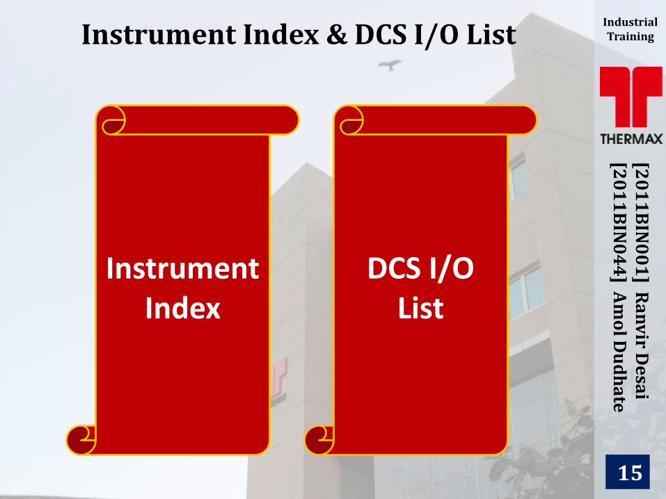
Instrument Index & DCS I/O List
15
[20
11
BIN
00
1] R
an
vir D
esa
i [2
01
1B
IN0
44
] Am
ol D
ud
ha
te
Industrial Training
Instrument Index
DCS I/O List
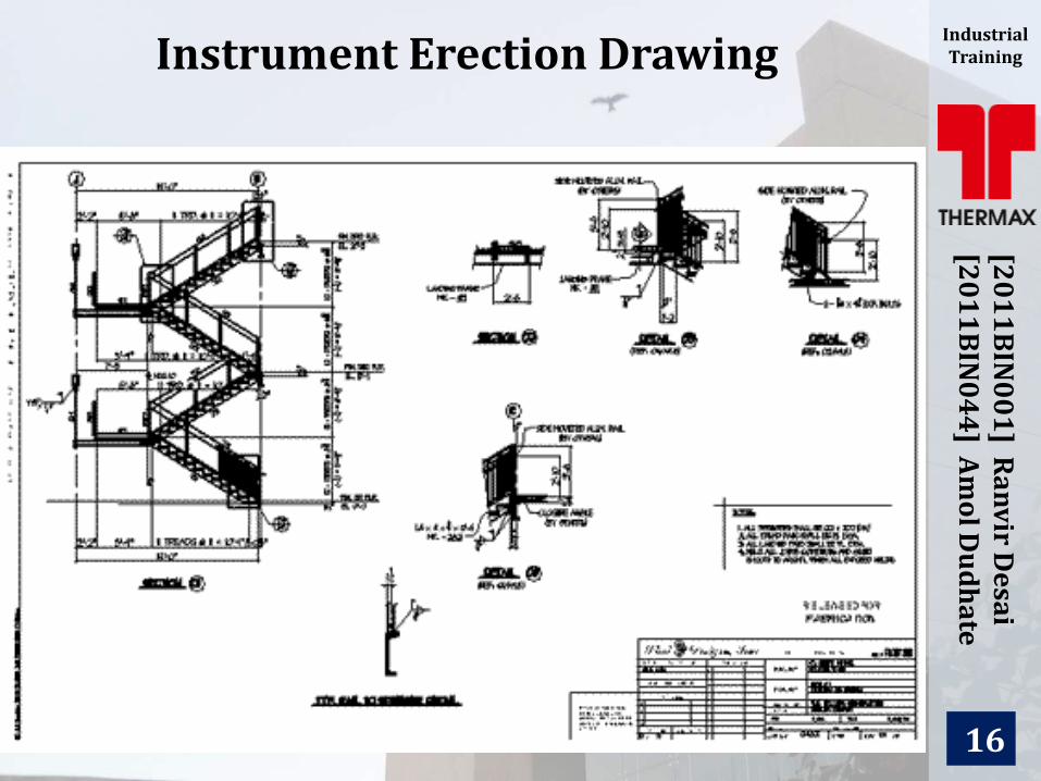
Instrument Erection Drawing
16
[20
11
BIN
00
1] R
an
vir D
esa
i [2
01
1B
IN0
44
] Am
ol D
ud
ha
te
Industrial Training

Boiler Major Equipment
17
[20
11
BIN
00
1] R
an
vir D
esa
i [2
01
1B
IN0
44
] Am
ol D
ud
ha
te
Industrial Training
1. Feed water system
2. Feed water heater
3. Deaerators
4. Economisers
5. Boiler drum
6. Boiler tubes
7. Superheaters
8. Attemperators
9. Condensate systems
10.Fuel system

Feed water system
18
[20
11
BIN
00
1] R
an
vir D
esa
i [2
01
1B
IN0
44
] Am
ol D
ud
ha
te
Industrial Training
1. The water supplied to the boiler, which is converted into steam, is
called feed water
2. The two sources of feed water are condensate or condensed steam
returned from the process and makeup water (treated raw water)
which must come from outside the boiler room and plant processes
3. DM water is used in boiler to avoid scaling
Feed water heater
1. Heaters are shell and tube heat exchangers with the feed water on
the tube side (inside) and steam on the shell side (outside)
2. Boiler efficiency is improved by the extraction of waste heat from
spent steam to preheat the boiler feedwater

Deaerators
19
[20
11
BIN
00
1] R
an
vir D
esa
i [2
01
1B
IN0
44
] Am
ol D
ud
ha
te
Industrial Training
1. The oxygen is mechanically removed in a deaerator
2. Oxygen is decreasingly soluble as the temperature is raised
3. This is done by passing a stream of steam through the feed water

20
[20
11
BIN
00
1] R
an
vir D
esa
i [2
01
1B
IN0
44
] Am
ol D
ud
ha
te
Industrial Training Economizers
A feed water economizer reduces steam boiler fuel requirements by
transferring heat from the flue gas to incoming feed water
Boiler drum
21
[20
11
BIN
00
1] R
an
vir D
esa
i [2
01
1B
IN0
44
] Am
ol D
ud
ha
te
Industrial Training
1. A boiler system consists of a steam drum and a mud drum
2. The steam drum is the upper drum of a water tube boiler where the
separation of water and steam occurs
3. The lower drum, called the mud drum, is a tank at the bottom of
the boiler that collects solids such as salts formed from hardness
and silica or corrosion products carried into the boiler
Boiler tubes
1. Boiler tubes are usually fabricated from high-strength carbon steel
2. The tubes are welded to form a continuous sheet or wall of tubes

22
[20
11
BIN
00
1] R
an
vir D
esa
i [2
01
1B
IN0
44
] Am
ol D
ud
ha
te
Industrial Training

Superheaters
23
[20
11
BIN
00
1] R
an
vir D
esa
i [2
01
1B
IN0
44
] Am
ol D
ud
ha
te
Industrial Training
1. The purpose of the superheater is to remove all moisture content
from the steam by raising the temperature of the steam above its
saturation point
2. The steam leaving the boiler is saturated, that is, it is in equilibrium
with liquid water at the boiler pressure (temperature)
Attemperators
1. Attemperation is the primary means for controlling the degree of
superheat in a superheated boiler
2. Attemperation is the process of partially de-superheating steam by
the controlled injection of water into the superheated steam flow

Condensate systems
24
[20
11
BIN
00
1] R
an
vir D
esa
i [2
01
1B
IN0
44
] Am
ol D
ud
ha
te
Industrial Training
1. Condensate tanks and pumps are major points for oxygen to enter
the condensate system and cause corrosion
2. These points should be monitored closely for pH and oxygen ingress
and proper condensate treatment applied
Fuel system
1. Their primary functions include transferring the fuel into the boiler
and distributing the fuel within the boiler to promote uniform and
complete combustion
2. The type of fuel influences the operational features of a fuel system

Boiler Safety Interlocks
25
[20
11
BIN
00
1] R
an
vir D
esa
i [2
01
1B
IN0
44
] Am
ol D
ud
ha
te
Industrial Training
1. Purge
2. Low Air Flow
3. Low Fuel Supply
4. Loss of Flame
5. Fan Interlock
6. Low Water
7. High Combustible content

26
[20
11
BIN
00
1] R
an
vir D
esa
i [2
01
1B
IN0
44
] Am
ol D
ud
ha
te
Industrial Training
Boiler Process