rapid integration tools for rapid application development____ carnegie mellon ___ software...
TRANSCRIPT

____ Carnegie Mellon___ Software Engineering Institute
Rapid Integration ToolsFor Rapid ApplicationDevelopmentA Case Study on Legacy
Integration
Amit MidhaRavindra SinghLakshmi Pratha Hari
Patrick R. Place, Advisor
December2004
DISTRIBUTION STATEMENT AApproved for Public Release
Distribution Unlimited
TECHNICAL REPORTCM U/SEI-2004-TR-023ESC-TR-2004-023
fW

_C Carnegie Mellon- Software Engineering Institute
Pittsburgh, PA 15213-3890
Rapid Integration Tools for RapidApplication Development
A Case Study on Legacy Integration
CMU/SEI-2004-TR-023ESC-TR-2004-023
Amit MidhaRavindra SinghLakshmi Pratha Hari
Patrick R. Place, Advisor
December2004
Integration of Software-Intensive Systems Initiative
Unlimited distribution subject to the copyright.
20051223 026

This report was prepared for the
SEI Joint Program OfficeESC/XPK5 Eglin StreetHanscom AFB, MA 01731-2100
The ideas and findings in this report should not be construed as an official DoD position. It is published in the interest ofscientific and technical information exchange.
FOR THE COMMANDER
Christos ScondrasChief of Programs, XPK
This work is sponsored by the U.S. Department of Defense. The Software Engineering Institute is afederally funded research and development center sponsored by the U.S. Department of Defense.
Copyright 2005 Carnegie Mellon University.
NO WARRANTY
THIS CARNEGIE MELLON UNIVERSITY AND SOFTWARE ENGINEERING INSTITUTE MATERIAL ISFURNISHED ON AN "AS-IS" BASIS. CARNEGIE MELLON UNIVERSITY MAKES NO WARRANTIES OF ANYKIND, EITHER EXPRESSED OR IMPLIED, AS TO ANY MATTER INCLUDING, BUT NOT LIMITED TO,WARRANTY OF FITNESS FOR PURPOSE OR MERCHANTABILITY, EXCLUSIVITY, OR RESULTS OBTAINEDFROM USE OF THE MATERIAL. CARNEGIE MELLON UNIVERSITY DOES NOT MAKE ANY WARRANTY OFANY KIND WITH RESPECT TO FREEDOM FROM PATENT, TRADEMARK, OR COPYRIGHT INFRINGEMENT.
Use of any trademarks in this report is not intended in any way to infringe on the rights of the trademark holder.
Internal use. Permission to reproduce this document and to prepare derivative works from this document for internal use isgranted, provided the copyright and "No Warranty" statements are included with all reproductions and derivative works.
External use. Requests for permission to reproduce this document or prepare derivative works of this document for externaland commercial use should be addressed to the SEI Licensing Agent.
This work was created in the performance of Federal Government Contract Number F19628-00-C-0003 with CarnegieMellon University for the operation of the Software Engineering Institute, a federally funded research and development
center. The Government of the United States has a royalty-free government-purpose license to use, duplicate, or disclose thework, in whole or in part and in any manner, and to have or permit others to do so, for government purposes pursuant to the
copyright license under the clause at 252.227-7013.
For information about purchasing paper copies of SEI reports, please visit the publications portion of our Web site(http://www.sei.cmu.edu/publications/pubweb.htmIl).

Table of Contents
Background and Acknow ledgem ents ................................................................... vii
Abstract .................................................................................................................. ix
1 Introduction ................................................................................................ 11.1 Purpose and O bjective .......................................................................... 1
1.2 Project Requirem ents ............................................................................ 3
1.3 Project Plan and Tracked Report ........................................................... 4
1.4 Structure of the Docum ent ................................................................... 4
2 Identification and Classification of Tools .................................................. 72.1 List of Tools ........................................................................................... 7
2.2 Tool Selection Criteria .......................................................................... 7
2.3 Classification Param eters ...................................................................... 8
2.4 Tool Evaluation ................................................................................... 15
3 Evaluation Using a M odel Problem ........................................................ 173.1 Purpose .............................................................................................. 17
3.2 M odel Problem Selection ................................................................... 173.2.1 Model Problem s ....................................................................... 173.2.2 Problem Selection ................................................................... 18
3.3 M odel Problem Description ................................................................. 20
3.4 Tool Evaluation using M odel Problem .................................................. 22
4 Conclusions .............................................................................................. 294.1 Lessons Learned ................................................................................ 29
4.2 Future Directions of the Research ...................................................... 30
4.3 Rem arks .............................................................................................. 30
Appendix A Tool Studies and Analysis ......................................................... 31
Appendix B Tool Evaluation Reports ............................................................. 45
Appendix C Model Problem and Analysis .................................................... 59
CMU/SEI-2004-TR-023

Appendix D Commercial Off-the-Shelf Components .................................... 69
Appendix E Trading Bond System COCOTS Estimation Details ................ 75
Appendix F Project Details ............................................................................ 81
Glossary of Technical Terms ............................................................................. 85
References/Bibliography ................................................................................... 91
ii CMU/SEI-2004-TR-023

List of Figures
Figure 1: Evaluation Process for the Rapid Integration Tools ............................. 2
Figure 2: Evaluation Framework ........................................................................ 3
Figure 3: Graph Showing Characteristics of the Three Tools Selected ........ 16
Figure 4: High-Level Context Diagram of Trading Bond System ...................... 20
Figure 5: Structure of the Model Problem ........................................................ 22
Figure 6: Model Solution-High-Level Context Diagram ................................... 24
Figure 7: Graph that Explains the Estimated vs. Actual Effort and Cost ........... 27
Figure 8: Legacy Market Data Subsystem ...................................................... 60
Figure 9: Legacy Contribution Subsystem ...................................................... 61
Figure 10: Logical View of the System ............................................................... 65
Figure 11: Feeder Component Specification ...................................................... 70
CMU/SEI-2004-TR-023
iv CMUISEI-2004-TR-023

List of Tables
Table 1: Classification Parameters - Technical and Non-Technical ................... 8
Table 2: Weights Assigned to Parameters Based on Rules of Thumb ............ 10
Table 3: Prioritized List of Quality Attributes .................................................. 22
Table 4: Top Three Risk List ......................................................................... 25
Table 5: Variance Calculator .......................................................................... 26
Table 6: Posteriori Evaluation Criteria Satisfied by the Tools .......................... 27
Table 7: Tools Observations Conforming to Non-Functional Requirements ......... 28
Table 8: Milestones and Schedule of the Project ............................................ 82
CMU/SEI-2004-TR-023 v

vi CMU/SEI-2004-TR-023

Background and Acknowledgements
The project served as an educational elective that is a requirement for the PDC [Professional Devel-
opment Center] Scholars at Carnegie Mellon University-West Coast Campus for their MSIT-SECurriculum.
We would like to thank Patrick Place, Member of the Technical Staff at the Software Engineering In-stitute, Pittsburgh, for mentoring the research and providing guidance and direction.
We would also like to thank those listed below for their approval and support.
"* Dr. Lynn Robert Carter, Principal Fellow, West Coast Campus, Carnegie Mellon University
"* Patricia Oberndorf, Director, Dynamic Systems Program SEI
"* Dennis Smith, Lead, Integration of Software Intensive Systems Initiative
"* Dr. Scott Lewis, Senior Faculty, West Coast Campus
Industry Experts:
"* Gerry Miller, Chief Technology Officer, Microsoft Corporation, U.S. Central Region
"* Eric Newcomer, Chief Technology Officer, IONA Technologies
"* Richard. W. Metz, Director, Process, Architecture and Tools, Boeing Computer Services
"* Jim Farrell, Product Management, IBM Rational Software
CMU/SEI-2004-TR-023 vii

viii CMU/SEI-2004-TR-023

Abstract
This report investigates the rapid integration tools available in the current market. These tools aid inthe rapid integration of software systems and components. The research centers on a model problemthat requires such a tool to address legacy integration challenges. The report presents a genericevaluation framework for identifying and evaluating rapid integration tools and an evaluation of threeidentified tools. This evaluation engaged selected evaluation criteria based on the demands of themodel problem. A process reference is also included; this forms the guidelines for identification andevaluation of the tools with respect to other model problems.
CMU/SEI-2004-TR-023 ix

x CMUISEI-2004-TR-023

1 Introduction
1.1 Purpose and ObjectiveThis project involves the analysis of rapid integration tools available in the market, which aid in rapidintegration of software systems/components. The project is centered on a model problem that requiressuch a tool to address legacy integration challenges. The main outcome of this research includes
"* a generic evaluation framework for identifying and evaluating rapid integration tools. Theevaluation criteria are geared towards the model problem that belongs to a class of model prob-lems having integration/interoperability as the key concern.
"* an evaluation of three identified tools with respect to the evaluation criteria and the model prob-lem which forms the framework for evaluation of tools.
" a process reference to the Integration of Components Certificate at Carnegie Mellon West, whichforms the guidelines for the identification and evaluation of the tools with respect to other modelproblems.
CMU/SEI-2004-TR-023 1
Identify Model Identify List of RapidProblem Integration Tools
Requirements FeaturedGathered Gathered
I dentify, Critical K~Tool Evaluation,~,Requirements Based >on Technical
(Interatioand Non.TechnicalPes e Parameters,
Selected Selected
Requirements T
Model Problem RequirementsVs Tool Features
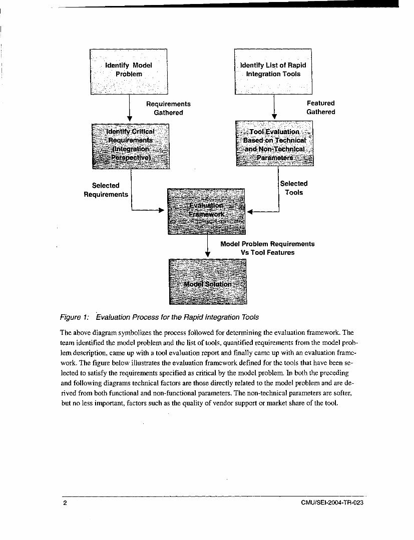
Figure 1: Evaluation Process for the Rapid Integration Tools
The above diagram symbolizes the process followed for determining the evaluation framework. The
team identified the model problem and the list of tools, quantified requirements from the model prob-lem description, came up with a tool evaluation report and finally came up with an evaluation frame-work. The figure below illustrates the evaluation framework defined for the tools that have been se-
lected to satisfy the requirements specified as critical by the model problem. In both the precedingand following diagrams technical factors are those directly related to the model problem and are de-rived from both functional and non-functional parameters. The non-technical parameters are softer,but no less important, factors such as the quality of vendor support or market share of the tool.
2 CMU/SEI-2004-TR-023
Technical Pa- Non Technicalrameters Parameters
Rules of thumb Weights
applied on se- Assignedlection of pa- based on
rameters Risk
Rapid Integration TolEv"a
Identified criticalrequirements forModel Solution Model Problem
Requirements
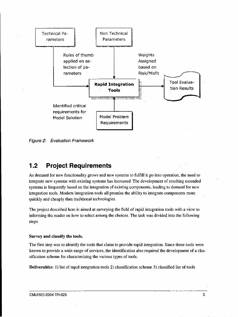
Figure 2: Evaluation Framework
1.2 Project Requirements
As demand for new functionality grows and new systems to fulfill it go into operation, the need to
integrate new systems with existing systems has increased. The development of resulting extendedsystems is frequently based on the integration of existing components, leading to demand for newintegration tools. Modem integration tools all promise the ability to integrate components morequickly and cheaply than traditional technologies.
The project described here is aimed at surveying the field of rapid integration tools with a view toinforming the reader on how to select among the choices. The task was divided into the following
steps.
Survey and classify the tools.
The first step was to identify the tools that claim to provide rapid integration. Since these tools wereknown to provide a wide range of services, the identification also required the development of a clas-
sification scheme for characterizing the various types of tools.
Deliverables: 1) list of rapid integration tools 2) classification scheme 3) classified list of tools
CMU/SEI-2004-TR-023 3

Evaluate the tools using a model problem
We expected that one or more of the classifications would contain a number of interesting rapid inte-gration tools. We chose a problem typical of the type of integration the tools were designed for andapplied a number of tools to that problem.
Deliverables: 1) preliminary evaluation scheme 2) model problem definition 3) reports detailingevaluation of tools' applicability to the model problem
Develop and document general evaluation criteria
Following the evaluation, the final step was to refine the evaluation criteria and document the refinedversions. The purpose was the creation of an instrument that would assist a developer in choosing the"right" rapid integration tool.
Deliverable: documented evaluation criteria for rapid integration tools. Depending on time, steps 2
and 3 may be repeated within another classification.
1.3 Project Plan and Tracked ReportWe followed a simple phased approach for executing the project with each phase divided into tasks
and related deliverables. Each deliverable is considered as a milestone and is derived from the initiallist provided by the SEI. Since the project is exploratory, it does not follow any standard softwaredevelopment life cycle, but we followed software engineering principles from the start. We used thework breakdown structure (WBS) and effort available from the elective to estimate a completion datebased on a given start date. The project ran over schedule perhaps indicating the problem of usingavailable effort as an artificial constraint on work to be performed.
1.4 Structure of the DocumentThis report is organized into three major chapters.
Chapter 1: Introduction to the Technical Report presents the purpose and objective of the project,the project description, background, requirements, project plan and tracked report and the structure of
the document.
Chapter 2: Identification and Classification of the Tools describes the list of tools identified as therapid integration tools and the evaluation framework applied to them for selection to work with the
model problem. The classification parameters that support the evaluation framework are the technicaland non-technical parameters.
Chapter 3: Model Problem and Tool Implementation explains the model problem selection andidentification of critical requirements as well as application of the tools and their assessments.
4 CMU/SEI-2004-TR-023

Chapter 4: Conclusions documents the lessons learned arising from the use of the specific tools.
Additionally, questions for future research are listed as are some concluding comments on the devel-
opment of the evaluation framework, including factors to consider before and after applying the
evaluation framework.
Appendices feature detailed descriptions of the tools evaluation, model problem, and other estima-
tions.
CMU/SEI-2004-TR-023 5

6 CMU/SEI-2004-TR-023

2 Identification and Classification of Tools
2.1 List of Tools
The first step in our approach is to identify the tools used for rapid integration. We discovered littledifference between integration tools and rapid integration tools.' We identified 11 rapid integrationtools designed for the rapid integration of applications from existing components.
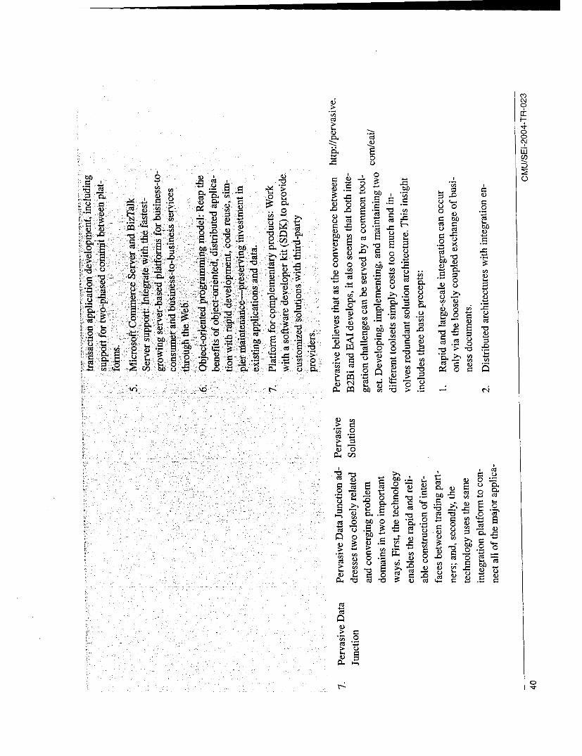
1. Pervasive Data Junction
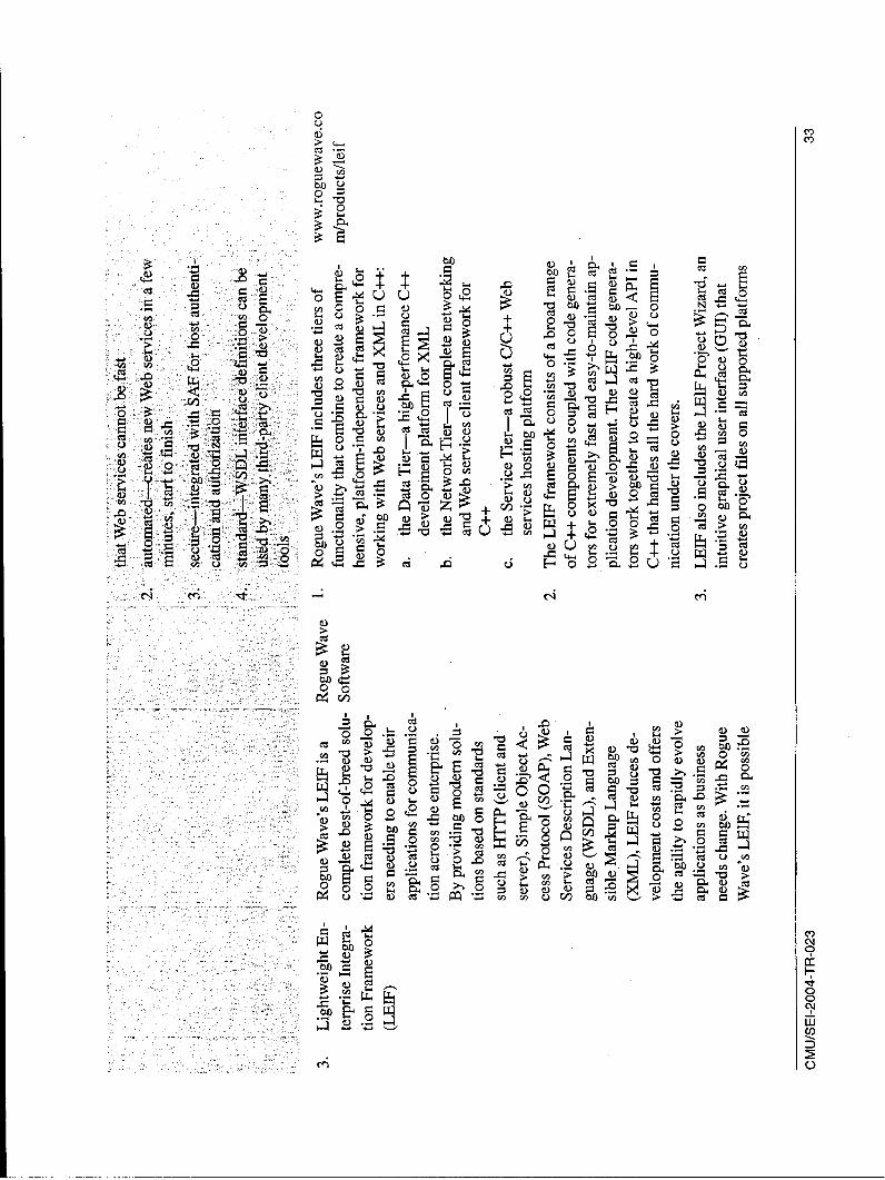
2. RoughWave's LEIF
3. IBM Rational Rapid Developer
4. Microsoft SQL Server
5. Host Integration Server
6. Microsoft BizTalk Server
7. IBM WebSphere Business Integration
8. Artix Relay, Encompass and Mainframe
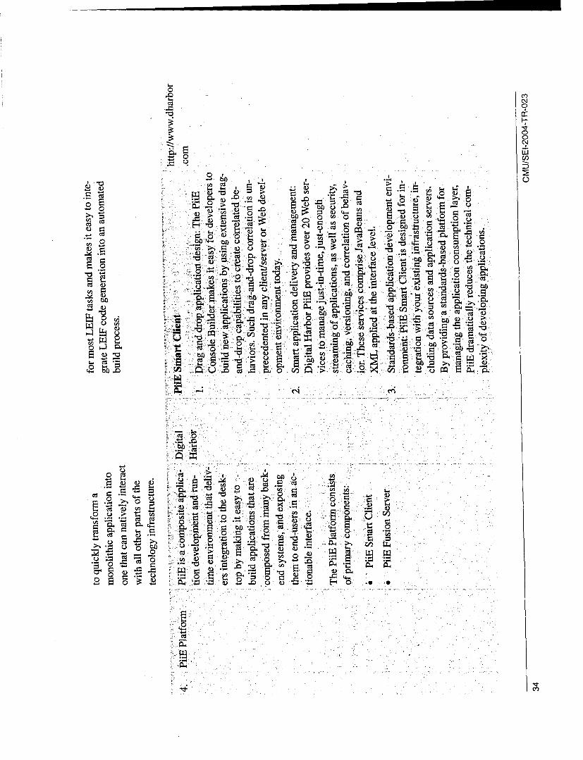
9. PiiE Smart Client and Fusion Server
10. InterSystem Ensemble
11. Jboss
For the above-listed tools, we collected information about their vendors' name and features. SeeAppendix A: Tools Studies and Analysis for more information.
2.2 Tool Selection CriteriaThe identified tools were filtered based on the model problem that will be described in Section 3.Since 11 tools seemed too many for starting the evaluation process, a short list was created based onthe following criteria.
1. Tool should be capable of solving a wide range of Enterprise Application Integration problems,especially the Legacy Integration problem.
2. Tool is able to provide communication between Java and C++ Components.
3. Tool has solid success stories associated with it.
Rapid is a concept that depends on the user's context. In some contexts, six months may be consideredrapid and in others, six hours could be too long. The tools themselves are, essentially, the same and a betterquestion is whether the integration tools speed the integration sufficiently to both produce timely applica-tions and cost less than not using the tools.
CMU/SEI-2004-TR-023 7

4. Tool has been in market for at least two to three years.
5. An evaluation version of the tool is available and the evaluation period is sufficient to evaluatethe tool.
Through application of these selection criteria the above list of 11 tools was short-listed to 3. The
three tools were
1. IBM Websphere
2. IBM Rapid Developer
3. LEIF ( Light-weight Enterprise Integration Framework)
2.3 Classification ParametersThe Classification Parameters used to evaluate tools can be technical or non-technical in nature. The
functional and non-functional requirements of the model problem form the technical parameters.Powell and colleagues observed] that apart from these technical parameters, some non-technical pa-
rameters arise from other business-oriented issues, such as cost and vendor, which play an important
role in the selection of a tool for rapid application development [Powell 97].
We identified 16 parameters (5 non-technical parameters and 11 technical parameters) for classifying
rapid integration tools. The table below gives a brief description of these parameters.
Table 1: Classification Parameters - Technical and Non-Technical
# Parameter DescriptionNon-Technical Parameters
1 Business market price of the tool
return on investment (ROI) of the tool (based on cost of the
tool compared to the estimated cost of manually integratingthe components)
foreseen risk in using the tools (lifespan of the tool, ease of
use, change frequency and so on)
2 Evaluation-Specific project life cycle in which the tool can be used (software con-
figuration, project planning, oversight and tracking and so on)
comparative report of other tools in similar domain
3 External References visibility and popularity of the tool in the market
4 Vendor Support quality and cost of the vendor support
access to architecture and design aspects of the tool
8 CMU/SEI-2004-TR-023

5 Tool-Specific integration with other tools and platform it can support
solution space the tool belongs to with respect to the problem
(domain specific)
reliability of the tool and the vendor maturity level based on
industry standards
skill set required to operate the tool
tailorability of the tool
extent to which data generated by the tool (performance logs
and so on) is configurable.
number of well-defined components that can be used
separately
performance of the tool
interactivity of the tool
sufficiency of documentation (user manual, installation guide
and so on) bundled with the tool
degree to which data generated by the tool can be used by
other tools
Technical Parameters
6 Security support offered by the tool for developing secure or safety
critical systems
7 Correctness capability of the tool for producing accurate results
8 Availability and capability of the tool for surviving system failure
Robustness
9 Ease of Use - Usability degree of learning curve associated with the tool
10 Downward and portability of applications developed using one version of the
CMU/SEI-2004-TR-023 9

Upward Compatibility tool to higher and/or lower versions of the same tool
11 Flexibility capability of tool for operating in different operating system
environments
12 Product Performance response time of the tool
13 Tailorability customizability of tool for meeting user-specific requirements
(user interface, enabling/disabling of features, enhancing the
tool by adding plug-ins, and so on)
14 Service Implementa- technical support/licensing cost associated with the tool
tion Coverage
15 Interoperability capability of tool to interoperate with other systems
16 Testability ability to test the functionality of the tool
Each rapid integration tool is analyzed based on the classification parameters above; it is rated on a scale
of 0 to 10, depending on how well it satisfies the parameters. The detailed evaluation of the tools is foundin Appendix A: Tool Studies and Analysis.
Assigning values to parameters while analyzing any tool may be tricky. Different individuals may comeup with different analysis results. In order to avoid this, we defined some rules of thumb, shown in Table 2below. These rules are so generic that they can be used to analyze any rapid integration tool.
Table 2: Weights Assigned to Parameters Based on Rules of Thumb
Weights
Parameters 0 1 to 3 4 to 7 8 to 10
10 CMU/SEI-2004-TR-023

Business Cost is very high Cost of the tool Cost of the tool sup- Cost of the tool
and has special doesn't support the ports the ROI; there supports the ROI;installation re- ROI; there are fre- are frequent changes there are two or
quirements (e.g., quent changes to the to the tool and the cost three releases of thespecific opera- tool and the cost of of learning the tool is tool a year and theting system, run- learning the tool is high. cost of learning thetime libraries). high. tool is low (e.g.,
because of exten-
sive Graphical UserInterface).
Evaluation- Tool is single-user Tool assists in the Tool supports collabo- Tool supports col-Specific and supports no collaborative devel- rative development by laborative develop-
integration with opment but cannot team, has its own con- ment by team, sup-organization's be integrated with figuration manage- ports configurationsoftware devel- the organization's ment and project and project man-opment life cycle software develop- management utility agement and can beand other tools. ment life cycle, but cannot be inte- integrated with
grated with other other tools to ex-tools. pand its current ca-
pabilities.
External Tool has recently Tool has received Tool has been used by Tool has been inReferences launched in the average response several large organiza- market for four or
market. from the user, has tions, has very few more years, ownedbeen in market for competitors, and has by software marketone to two years, several success stories leaders like IBM orand a similar tool by associated with its Microsoft, used byleading vendors use. large organizations,
(e.g., Microsoft, and has many suc-IBM) is available in cess stories associ-the market. ated its use.
Vendor Tool has no cus- Tool has limited Tool has good cus- Tool has effectiveSupport tomer support. customer support tomer support through customer support
through mail and online discussion fo- through online dis-telephone conversa- rum, mail and tele- cussion forum,tions only. phone conversations, email, and on-site
There is immediate consultation. Re-response to queries sponse is immediate
posted to Customer to queries posted to
CMU/SEI-2004-TR-023 11

Support Center. Customer SupportCenter.
Tool-Specific Tool doesn't sup- Tool supports inte- Tool supports integra- Tool supports inte-
port integration gration with two or tion with software gration with soft-with other tools. three other tools and configuration man- ware configuration
has complex inte- agement tools, testing management tools,gration process. tools, application testing tools, appli-
servers, and so on, cation servers and
and integration proc- so on, and integra-
ess is moderate and tion process is eas-requires manual set- ily performed via
tings. wizards. Tool sup-
ports custom devel-
opment to enhanceits features and us-
ability.
Security Tool doesn't pro- Tool supports few Tool supports most Tool supports most
vide any features standard security security mechanisms security mecha-
to aid in the im- mechanisms like currently used in the nisms currentlyplementation of encryption and au- market and but doesn't used in the marketsecurity mecha- thentication. support any custom and also supportsnism (encryption, development of secu- custom develop-authentication, rity mechanisms. ment of securityauthorization etc.) mechanisms.
Correctness Tool has no utility Tool supports lim- Tool supports stan- Tool performs vali-
for testing the ap- ited testing for the dard testing of the dation at every stepplication devel- application devel- application developed while developingoped by it. oped. through testing utili- the application.
ties bundled with the Also supports inte-tool. gration of other test-
ing tools (e.g., thirdparty applicationservers) to verify
the correctness of
the application cre-ated.
12 CMU/SEI-2004-TR-023
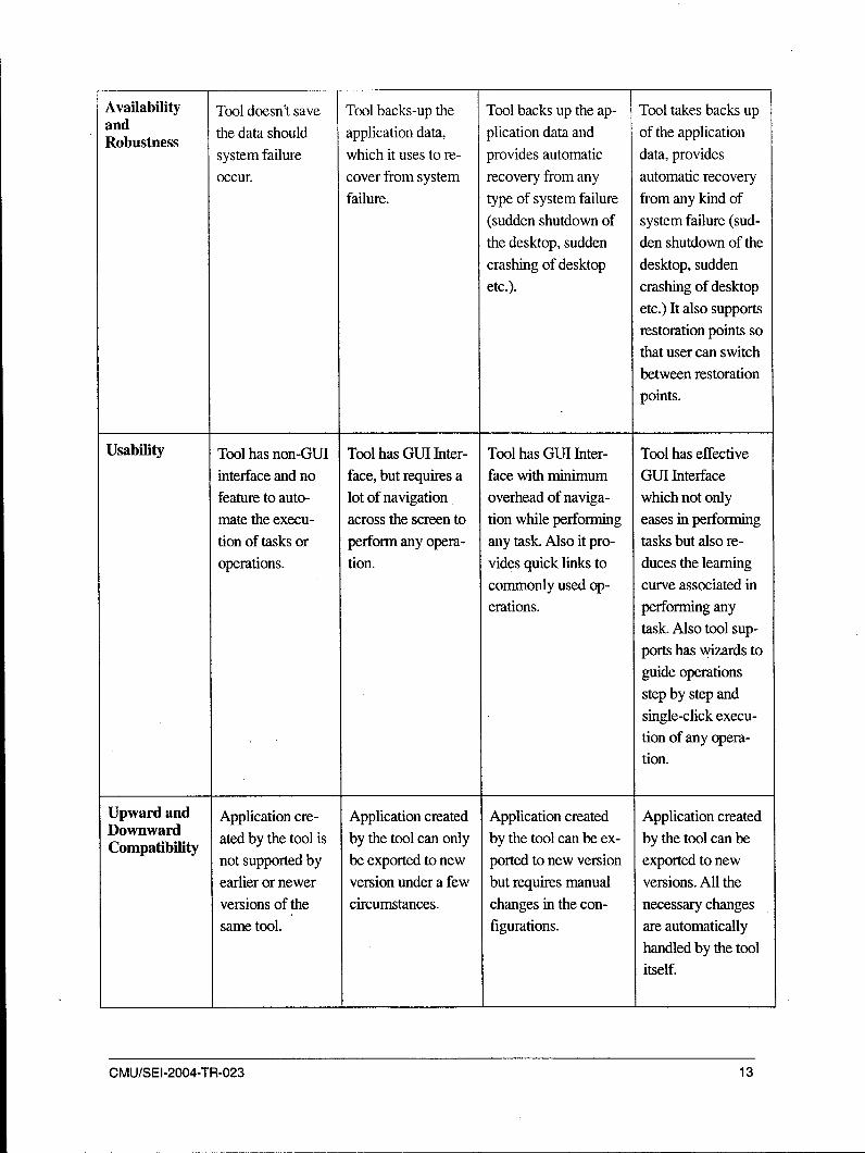
Availability Tool doesn't save Tool backs-up the Tool backs up the ap- Tool takes backs upandR n e the data should application data, plication data and of the applicationRobustness
system failure which it uses to re- provides automatic data, providesoccur. cover from system recovery from any automatic recovery
failure. type of system failure from any kind of(sudden shutdown of system failure (sud-the desktop, sudden den shutdown of thecrashing of desktop desktop, suddenetc.). crashing of desktop
etc.) It also supportsrestoration points so
that user can switchbetween restorationpoints.
Usability Tool has non-GUI Tool has GUI Inter- Tool has GUI Inter- Tool has effective
interface and no face, but requires a face with minimum GUI Interface
feature to auto- lot of navigation overhead of naviga- which not only
mate the execu- across the screen to tion while performing eases in performingtion of tasks or perform any opera- any task. Also it pro- tasks but also re-operations. tion. vides quick links to duces the learning
commonly used op- curve associated in
erations. performing anytask. Also tool sup-ports has wizards toguide operationsstep by step andsingle-click execu-tion of any opera-
tion.
Upward and Application cre- Application created Application created Application createdDownwardCompatibility ated by the tool is by the tool can only by the tool can be ex- by the tool can be
not supported by be exported to new ported to new version exported to newearlier or newer version under a few but requires manual versions. All theversions of the circumstances. changes in the con- necessary changessame tool. figurations. are automatically
handled by the toolitself.
CMU/SEI-2004-TR-023 13
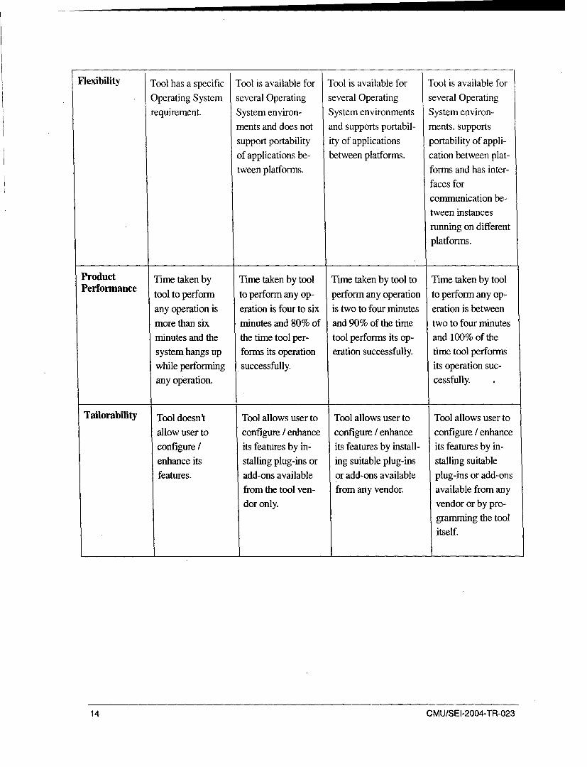
Flexibility Tool has a specific Tool is available for Tool is available for Tool is available for
Operating System several Operating several Operating several Operatingrequirement. System environ- System environments System environ-
ments and does not and supports portabil- ments, supportssupport portability ity of applications portability of appli-of applications be- between platforms. cation between plat-tween platforms. forms and has inter-
faces for
communication be-tween instancesrunning on different
platforms.
Product Time taken by Time taken by tool Time taken by tool to Time taken by toolPerformance tool to perform to perform any op- perform any operation to perform any op-
any operation is eration is four to six is two to four minutes eration is betweenmore than six minutes and 80% of and 90% of the time two to four minutes
minutes and the the time tool per- tool performs its op- and 100% of thesystem hangs up forms its operation eration successfully. time tool performswhile performing successfully, its operation suc-any operation. cessfully.
Tailorability Tool doesn't Tool allows user to Tool allows user to Tool allows user to
allow user to configure / enhance configure / enhance configure / enhanceconfigure / its features by in- its features by install- its features by in-enhance its stalling plug-ins or ing suitable plug-ins stalling suitablefeatures. add-ons available or add-ons available plug-ins or add-ons
from the tool ven- from any vendor, available from anydor only. vendor or by pro-
gramming the toolitself.
14 CMU/SEI-2004-TR-023

Service Tool has stringent Tool promotes Tool promotes evalua- Tool promotesImplementa- licensing policy evaluation copy but tion copy with ade- evaluation copytionCoverage and does not pro- the period is not quate customer sup- with adequate cus-
mote evaluation sufficient enough to port for any issues tomer support for
copies to experi- evaluate the tool. that arise during the any issues that arisement with the Also the licensing evaluation period but during the evalua-tool. Also it has cost is very high. the evaluation period tion period and also
high licensing cost is not sufficient the evaluation pe-and purchasing a enough to evaluate the riod is sufficientnew license is tool. The licensing enough to evaluatealmost equal to cost is nominal, the tool fully. Thethe cost of the tool licensing cost isitself, nominal.
Interopera- Results produced Results produced by Results produced by Results produced bybility by the tool cannot the tool can be ex- the tools can be ex- the tools can be ex-
be exported to ported to other for- ported to other for- ported to other for-
other formats mats (Word docu- mats (Word docu- mats (Word docu-(Word document, ment, html, jpeg, ment, html, jpeg, etc.) ment, html, jpeg,html, jpeg, etc.) etc.) but it does not and it supports inter- etc.) and it supportsand it doesn't have support inter-tool tool communication. inter-tool communi-any interface to communication. cation. Also tool cancommunicate with produce results thatother tools. can be ported to any
platform.
Testability of Tool doesn't vali- Tool does minimal Tool does validation Tool does validation
Output date the output validation and the of the results and the throughout and the
produced. accuracy of the re- accuracy of the result accuracy of the re-
sult is about 70%. is about 80%. sult is 100%.
2.4 Tool EvaluationThe three short-listed tools were evaluated for these technical and non-technical parameters. SeeAppendix A: Tool Studies and Analysis for the Tool Evaluation Report.
The following graph shows the summary of the parameter values for each tool.
CMU/SEI-2004-TR-023 15
Tools v/s Parameter
1 0 1 ... .. ... . .. ... . . ... .. . . . . ..... ... . . ... .----- o ---... . ... . . ... - . .... . ... . .... . . ...... ...... . .. ........... . ..... ..... .... . . . . ... . . . . . . . . . . .-- ----
6 1 , IBM Websphere
5* LEIF
1-I3I L IBM Rational Rapid Developer
(P ý0' -, Po,;I/ •o i oJ ' ' /'
Parameter
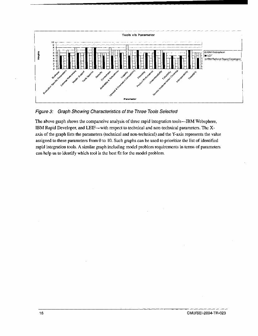
Figure 3: Graph Showing Characteristics of the Three Tools Selected
The above graph shows the comparative analysis of three rapid integration tools-IBM Websphere,IBM Rapid Developer, and LEIF-with respect to technical and non-technical parameters. The X-
axis of the graph lists the parameters (technical and non-technical) and the Y-axis represents the value
assigned to these parameters from 0 to 10. Such graphs can be used to prioritize the list of identifiedrapid integration tools. A similar graph including model problem requirements in terms of parameterscan help us to identify which tool is the best fit for the model problem.
16 CMU/SEI-2004-TR-023

3 Evaluation Using a Model Problem
3.1 PurposeThis section describes the evaluation of the tools using a selected model problem. The model problemselection criteria, the description of the model problem, and the evaluation of the tools are high-lighted. In describing the model problem selection criteria we also explain the sequence of steps wefollowed in making our selection. We briefly describe the model problem with respect to the non-functional requirements and the problem statement. Finally, we explain the tool evaluation using themodel problem; here we've applied the structure of the selected model problem as described by KurtWallnau in Building Systems from Commercial Components [Wallnau 02]. The assessment resultsobtained from this evaluation show the extent to which the tools satisfied the post evaluation criteriaand the problem's non-functional requirements.
3.2 Model Problem Selection
3.2.1 Model Problems
We found three potential model problems (descriptions follow); each problem is appropriate to a par-ticular type of integration.
Web Service Enablement
A company uses the enterprise integration technology as well as XML technology to make customeraccount information accessible via a Simple Object Access Protocol (SOAP)-based Web services in-terface.
The implementation of this solution requires retrieving and combining information from two sourceapplications. The first application is a custom CORBA system that provides historical customer sup-port information. The second application is Siebel, which provides customer purchase information.
Legacy Integration
Bond traders working online must send prices for a large number of bonds to several different tradingvenues, each with its own user interface; this disrupts the workflow of their bond trading desk.
The system solution should minimize the minutiae of pricing all traders' bonds and provide an ad-vanced analytic functionality, specific to the bond market, in a single encapsulated user interface.
This system would utilize legacy components on the server side.
CMU/SEI-2004-TR-023 17

Business Application Integration
Three companies use different business processes involving different sets of assumptions. Middle-ware must be utilized as the integration point for communicating among the business processes.
3.2.2 Problem Selection
The following five steps were followed
Step 1: Identify the problem that must be solved through integration.
In this case we identified the following types of integration based on our prior knowledge.
1. Middleware Integration
2. Service Oriented Integration
3. Web Service Integration
4. Legacy Integration
5. Enterprise Application Integration
Step 2: Based on research on the various application integration types we chose three that would pro-vide the best opportunity for using the tools that we have selected.
1. Legacy Integration
2. Business Application Integration
3. Web Service Enablement
Step 3: Analysis and study on the three model problems were made based on answering the following
questions.
1. Which problem gives a way to integrate two different technologies?
Of the three problems presented, we found that the Trading Bond System required a solution thatwould integrate components built using two different technologies (in this case programming lan-guages), as evidenced by its case study report:
Traders needed a very responsive application on both Windows NT and Solaris workstations.Therefore, we decided to implement the client application as a Java thick client because of itsplatform independence and its ability to quickly respond to user input and market data. On the server
side, we are inheriting legacy C++ components that our system will utilize [Simon 03].
The Trading Bond system meets the criterion of providing a way to integrate two technologies. The
solution requires integration of a Java based component and C++ based components, which can be
done by building a pair of Java gateways to communicate with the C++ server-side components[Simon 031. Details of the Trading Bond System case are available athttp://www.eaipattems.com/BondTradingCaseStudy.html.
18 CMU/SEI-2004-TR-023

2. Which problem is faced in the real world often?
A demand exists in government and industry for existing systems to be updated or integrated with thecurrent technology. Many applications require technology independence and interoperability withvarious applications that were developed using different technologies. Moreover, in the current indus-trial scene there is a drive toward production of tools for the integration of Java-based componentsand C++ based components. The Trading Bond System is therefore quite typical of real-world scenar-ios.
3. Which problem is very specific and solvable within the specified time constraint?
We found that legacy integration for the Trading Bond System best met these criteria. We were ableto download two specific components provided by Dukascopy, an online trading application, whichmapped with the Trading Bond System scenario. This bode well for solving the problem on time.
We did not find the same with the customer account information problem to be solved through WebService enablement: Here the application was generic and we were not able to find the specific attrib-utes to be addressed or specific requirements to be fulfilled. We realized that it might take consider-able time to establish which tools were needed. This presented a problem, given time constraints andresource availability. We did not have enough time to create a simulation of the CORBA System andthe Siebel system.
The problem that might have been solved through Business Integration did not meet this criterion.This involved three companies who required communication among their different business proc-esses. The business processes to be integrated were not well defined or specific. The time required forcreating simulated processes and then integrating them did not meet our constraints.
4. Which of the other classes of integration does this model problem address?
The chosen problem could also be used to assess service-oriented integration insofar as it is reason-able to treat the problem components as services. Additionally, the middleware, application and Web-based integration classes could be addressed by the Trading Bond system.
Step 4: Identify the model problem that fit into the evaluation framework based on the above identi-fied questions.
Step 5: Having identified the model problem to be solved, we now present details regarding the Trad-ing Bond system relevant to further application development using the integration tools.
CMU/SEI-2004-TR-023 19

3.3 Model Problem DescriptionThe Trading Bond system best met the problem criteria and highlights the necessity of integration, forcommunication purposes, between various components with various user interfaces and communica-
tion protocols. The following table shows an analysis of the original problem statement into a prob-lem description describing the various actors and also constraints on the solution.
The problem of bond traders to send prices for a large number of bonds to several
different trading venues, each with its own user interface
affects bond traders
the impact of which is to disrupt the streamline of the workflow of their bond trading desk
a successful solution would be a bond pricing system to minimize the minutiae of pricing all of
their bonds combined with advanced analytic functionality specific
to the bond market in a single encapsulated user interface.
Market Data _ nalytin s TaiP'rice ° Fee ,rnVenues
Client Application(Analytics
Configuration)
Figure 4: High-Level Context Diagram of Trading Bond System
First, market data comes into the system. Market data is data regarding the price and other properties
of the bond representing what people are willing to buy and sell the bond for on the free market. The
market data is immediately sent to the analytics engine that alters the data. Analytics refers to mathe-
matical functions for financial applications that alter the prices and other attributes of bonds. Theseare generic functions that use input variables to tailor the results of the function to a particular bond.
The client application that will run on each trader desktop will configure the analytics engine on a per
trader basis, controlling the specifics of the analytics for each bond the trader is pricing. Once the
20 CMU/SEI-2004-TR-023

analytics are applied to the market data, the modified data is sent out to various trading venues wheretraders from other firms can buy or sell the bonds.
The following are some of the non-functional requirements that the system should address, in order ofpriority. The scope of this model problem extends to only the highest priority quality attributes se-lected by the team.
Integrability:
"On the server side, we are inheriting legacy C++ components that our system will utilize."
The system should be integrable with the legacy C++ components which forms the Market data feedpricing subsystem and the thick client application which will be a Web-based thick Java client.
Performance:
"Traders need a very responsive application"
Two attributes of performance are essential to this responsiveness.
1. Scalability: Measured as the number of traders who will be accessing the system and the sys-tem's capability for accommodating them.
2. Response Time: The system should be able to respond to the user without significant delay [herewe say less than 5 sec, assuming that it is a Web-based application]
Portability:
"Traders need a very responsive application on both Windows NT and Solaris workstations."
The application should be portable to any platform based on the demands of the trader's needs.
The quality attribute that will be addressed in this execution of the model problem is highlighted inTable 3.
CMU/SEI-2004-TR-023 21
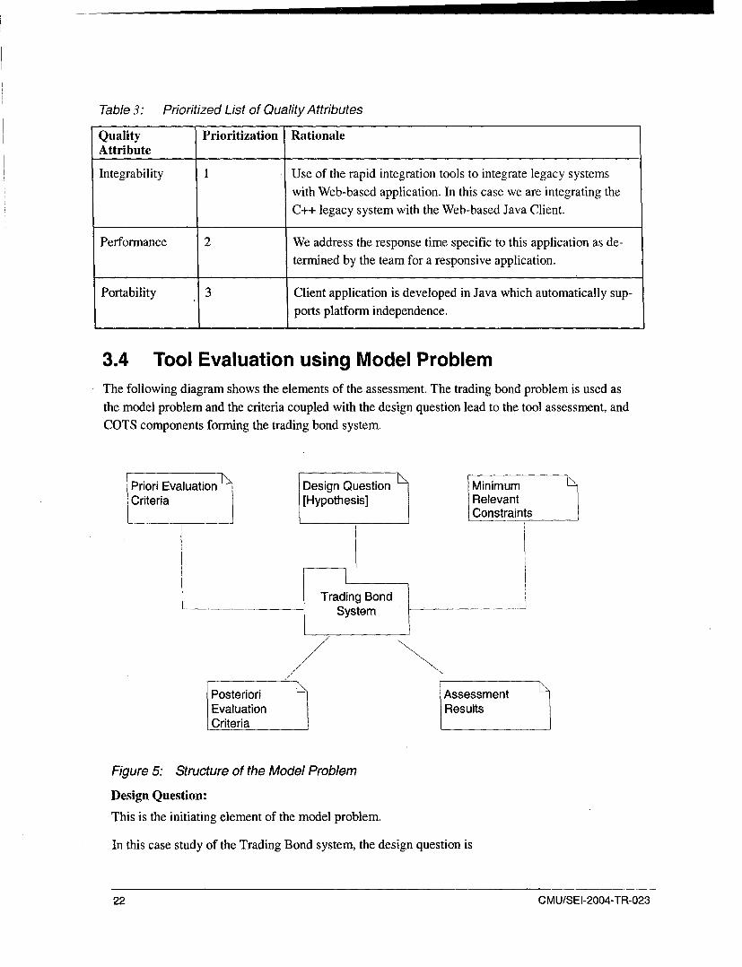
Table 3: Prioritized List of Quality Attributes
Quality Prioritization RationaleAttribute
Integrability 1 Use of the rapid integration tools to integrate legacy systemswith Web-based application. In this case we are integrating theC++ legacy system with the Web-based Java Client.
Performance 2 We address the response time specific to this application as de-termined by the team for a responsive application.
Portability 3 Client application is developed in Java which automatically sup-ports platform independence.
3.4 Tool Evaluation using Model ProblemThe following diagram shows the elements of the assessment. The trading bond problem is used asthe model problem and the criteria coupled with the design question lead to the tool assessment, andCOTS components forming the trading bond system.
Priori Evaluation Design Question MinimumCriteria [Hypothesis] Relevant
Constraints
Trading BondSystem
/
Posteriori AssessmentEvaluation ResultsCriteria
Figure 5: Structure of the Model Problem
Design Question:
This is the initiating element of the model problem.
In this case study of the Trading Bond system, the design question is
22 CMU/SEI-2004-TR-023

Is it possible to integrate the Java and legacy C++ components that are obtained off the shelf from theDukascopy stock quote Web site, using the rapid integration Tools?
Hypothesis: A wrapper component [integration point] that provides the communication between theJava thick client and the legacy server side C++ component can be constructed using the rapid inte-gration Tools.
Priori Evaluation Criteria:
These are the criteria to be satisfied by the model solution. They were obtained by analyzing the ap-plication specifics given in the case study. They are centered on integration techniques and use of in-tegration tools. These evaluation criteria are formulated based on the hypothesis that we have ad-dressed related to the model problem. These criteria help in defining with the Standard's compliancethat the tools must meet in order to satisfy the requirements.
Criterion #1: A Java to C++ translator is required. Java thick Client talking with C++ Legacy Servers
Criterion #2: Messaging Bridge to support the communication between cross-language applications[C++ and Java]
Criterion #3: Single point of access is required to communicate with the gateways of the legacy serv-ers.
The criteria form the model problem requirements for the integration implementation using the tool.Thus according to Criteria #1, #2, and #3, the tool should be able to provide a communicationmechanism, a messaging bridge and a single point access between the Java and C++ components. Inthis case the tools IBM WebSphere and the LEIF help in achieving these developments.
Minimum Relevant Constraints
The following constraints are based on what is feasible to provide in the model solution to address theabove mentioned priori criteria:
1. This is a short-term project that involves rapid development; hence the use of rapid integrationtools to create the Java to C++ translator, messaging bridge and single point access mechanism,which are the priori criteria of the model problem.
2. The business processes of the model problem are not a focal point, since they are addressed bythe off-the-shelf components that are downloaded from the Dukascopy site.
3. The tool selection is restricted to the major functionalities provided by the tool with respect tothe model problem's priori criteria.
The development and deployment environment are the same; hence the performance of the modelsolution is constrained.
CMU/SEI-2004-TR-023 23

Model Solution: Trading Bond System
A simple solution that clarifies how the model solution was implemented is provided below:
Find Discovery Publish
( Agencies
Service I
Requestor 1
I Interact
Client Service
Service ProviderRequestor n......
C++ Legacy ServersJava Gateways
Figure 6: Model Solution-High-Level Context Diagram
The Java Gateways are considered the Service Requestor and the Java Web Services are implementedusing the IBM WebSphere. These Java Web Services are the Client side application required for
communicating with the C++ Legacy servers, in this case the Market Data Feed Component obtained
from the Customized Dukascopy Data Feed (CDDF) http://www.dukascopy.com/english/ddfmain/. The C++ Legacy Servers are the service providers. The inner workings of the C++
Component and the Java Component were not considered; it was the integration between these com-
ponents that was implemented using the Tools. The Discovery Agencies used were the UDDI Ser-vices, which were automatically set in the IBM WebSphere tool.
The System uses the simple publish-subscribe model for the implementation of the integration
through discovery agencies and SOAP is the communication protocol that establishes the interaction
between the two Web services.
Posteriori Evaluation Criteria
Criterion #1:
Installation and development environment for the identified solution tools are in place.
Criterion #2:The off-the-shelf components architecture and design maps with the model problem requirements.
Criterion #3:The integration of the two COTS components is accomplished using the rapid integration tools
24 CMU/SEI-2004-TR-023

The above criteria help in evaluating whether the tools are able to meet the requirements of the model
problem and whether they are able to conceptualize the hypothesis that has been defined for this
model problem.
Assessment Results
The assessment results are enumerated based on the following factors:
1. risks encountered and mitigated while using the contingency approach
2. the size, effort, and cost variance involved when using the rapid integration tools and when notusing the rapid integration tools
3. product outcome explaining the steps that brought success and those that resulted in failure inthe development using rapid integration tools
These assessments help in evaluating the tools as they apply to the model problem. In this case theyare restricted with respect to the legacy integration of cross-language platforms.
Risks Encountered and Mitigated
The following table describes the major risks that we encountered and mitigated through contingencyplans.
Table 4: Top Three Risk List
No. Risk Risk Management Strategy Status
. MiaContingencyS Mitigation
Activities Trigger Activities
1 Tools iden- 90% .9 1 Collect the The tools are Determine which Closetified are tools based on not able to tools support thenot suitable the model produce a communicationfor solving problem's mechanism mechanism. Inthe model critical re- that solves this case C++problem quirements the commu- Web Services are
nication be- created using thetween Java Apache AxisGateways C++. The integra-and the C++ tion of the C++Legacy Component withServer. the Java Compo-
nent is accom-plished via the
LEIF.
CMU/SEI-2004-TR-023 25
No. Risk Risk Management Strategy Status
_ MiiaContingency= Mitigation
Activities Trigger Activities
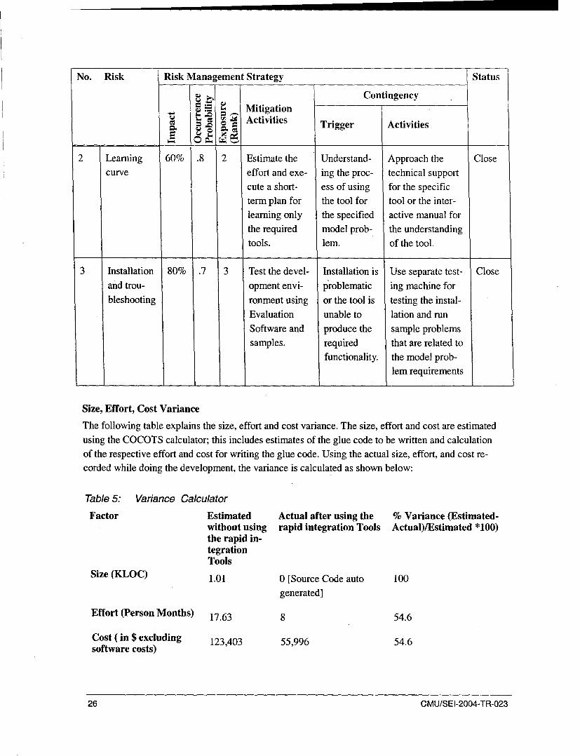
2 Learning 60% .8 2 Estimate the Understand- Approach the Closecurve effort and exe- ing the proc- technical support
cute a short- ess of using for the specificterm plan for the tool for tool or the inter-learning only the specified active manual for
the required model prob- the understandingtools. lem. of the tool.
3 Installation 80% .7 3 Test the devel- Installation is Use separate test- Closeand trou- opment envi- problematic ing machine forbleshooting ronment using or the tool is testing the instal-
Evaluation unable to lation and run
Software and produce the sample problemssamples. required that are related to
functionality, the model prob-lem requirements
Size, Effort, Cost Variance
The following table explains the size, effort and cost variance. The size, effort and cost are estimated
using the COCOTS calculator; this includes estimates of the glue code to be written and calculationof the respective effort and cost for writing the glue code. Using the actual size, effort, and cost re-corded while doing the development, the variance is calculated as shown below:
Table 5: Variance Calculator
Factor Estimated Actual after using the % Variance (Estimated-without using rapid integration Tools Actual)/Estimated *100)the rapid in-tegrationTools
Size (KLOC) 1.01 0 [Source Code auto 100
generated]
Effort (Person Months) 17.63 8 54.6
Cost (in $ excluding 123,403 55,996 54.6software costs)
26 CMU/SEI-2004-TR-023

Estimated Vs Actual
140 -,120 .100.
80 Ei Estimated
60 ----. Actual40200
Size Person Month Cost
Factors
Figure 7: Graph that Explains the Estimated vs. Actual Effort and Cost
Product outcome
The product developed using these tools should have adhered to the a posteriori evaluation criteriathat we arrived at and also the non-functional requirements of the model problem.
Table 6: Posteriori Evaluation Criteria Satisfied by the Tools
Criterion Description Observation
1 Installation and development environments Yes. All three tools satisfied thisare in place for the identified solution tools. criterion.
2 The off-the-shelf components architecture The components do not map exactlyand design satisfy the model problem re- with respect to the implementationquirements. model as required by the model prob-
lem. They satisfied the functional
requirements.
3 The integration of the two COTS compo- The tools, especially IBM Web-nents is accomplished using the rapid inte- Sphere, LEIF, and Apache Axis C++,gration tools. were used for creating and integrating
the Web services of the COTS
components.
The product outcome is also validated when the non-functional requirements are satisfied by the vari-
ous tools.
CMU/SEI-2004-TR-023 27
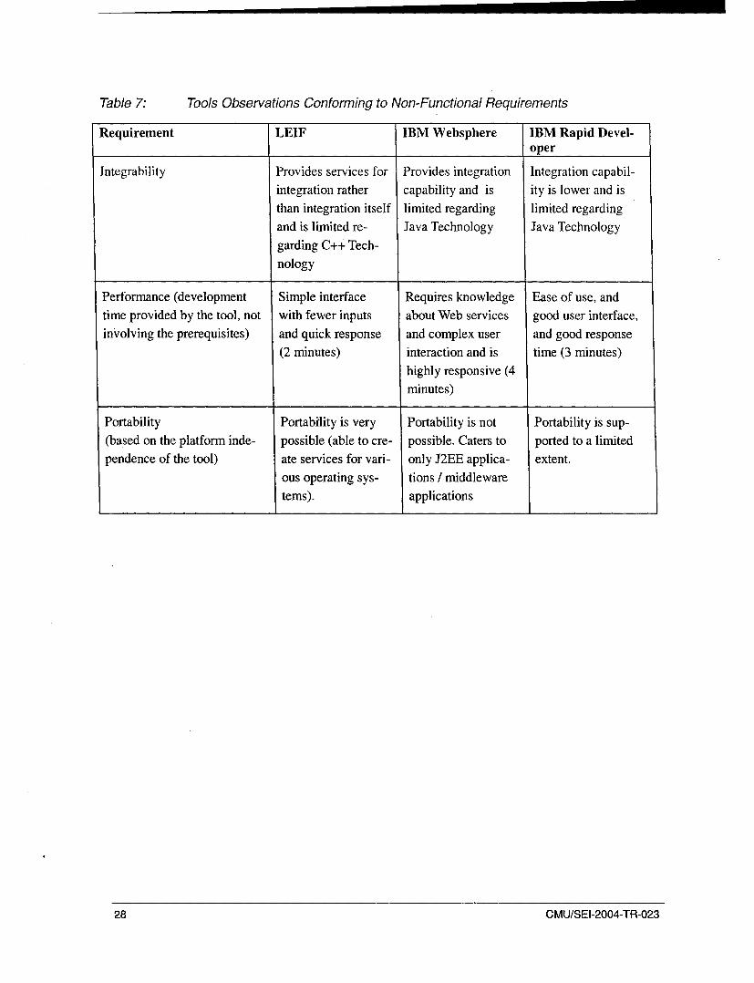
Table 7: Tools Observations Conforming to Non-Functional Requirements
Requirement LEIF IBM Websphere IBM Rapid Devel-oper
Integrability Provides services for Provides integration Integration capabil-integration rather capability and is ity is lower and is
than integration itself limited regarding limited regardingand is limited re- Java Technology Java Technology
garding C++ Tech-nology
Performance (development Simple interface Requires knowledge Ease of use, andtime provided by the tool, not with fewer inputs about Web services good user interface,inVolving the prerequisites) and quick response and complex user and good response
(2 minutes) interaction and is time (3 minutes)
highly responsive (4minutes)
Portability Portability is very Portability is not Portability is sup-(based on the platform inde- possible (able to cre- possible. Caters to ported to a limitedpendence of the tool) ate services for vari- only J2EE applica- extent.
ous operating sys- tions / middleware
tems). applications
28 CMU/SEI-2004-TR-023

4 Conclusions
In this section, the lessons learned from the highlights and lowlights of the whole research work havebeen documented. Additionally,'we suggest some directions for potential future work based on thisinvestigation.
4.1 Lessons Learned
What Went Right
1. Being able to download evaluation copies helped in the installation and testing of the tools.
2. The required additional software necessary for the installation and configuration of the selectedtools (for instance, LElF requires VC++) was provided by our university.
3. The creation of services out of the COTS components took almost no time when the tools wereused. (The user should be aware of the component and the business logic required to create aservice from that component.)
4. IBM WebSphere proved to be a highly interactive tool which enhanced the usability and intelli-gibility of the feeder component (Java) and was able to generate the Web services from thesecomponents in just 4-5 minutes.
5. The Communication between the two components using the SOAP mechanism was successfullycompleted using the IBM WebSphere.
What Went Wrong
1. Expiration of the evaluation copies often forced us to change machine configurations and set-tings in the development environment.
2. The COTS component was revised and is no longer freely available, thus this experiment isn'tfreely repeatable.
3. No configuration management of source files is maintained due to the auto generation of thesource code by the tools.
4. We could only run the application in the version of the evaluation copy that created it. Running itin a different version required extra effort and time for reconfiguration and caused data loss.
5. LEIF was unable to generate the WSDL file for the C++ Component, so it involved extra effortto find an alternative to do the same. [This was due to the incompatibility in the versioning of thesource code of the Market Data Feed Component (C++).]
CMU/SEI-2004-TR-023 29

4.2 Future Directions of the ResearchIn this section we want to highlight the Evaluation Framework's applicability to the other modelproblems and tools by answering the following questions.
"* Is the framework applicable to all tools and all model problems?
"* How much time is needed to modify your framework when you must support multiple modelproblems?
"* How much effort is needed in terms of searching for technologies and characterizing the modelproblem different ways?
4.3 Remarks
While the development of the evaluation framework took more time than expected, we believe that
the result is worthwhile. The framework, without change, can be used for a significant number of
similar evaluations and, with minor change, could be used for a wider range of problems. Further, theevaluations contained herein demonstrate that it is possible to use the framework to distinguish be-tween tools.
The difficulties we had with the various tools suggest that, although rapid integration technologies arebeing widely hyped, in practice the tools still leave something to be desired. While it is possible touse the tools to integrate legacy components more efficiently than without the tools, the difficulties
suggest that more work remains to be done on the tools themselves (as well, perhaps, as the targetenvironment of Web services).
30 CMU/SEI-2004-TR-023

0) 0 4
1. 0 s a) co
0 7aý) -a )* _o
-, ro -gd 40- cl
0)o,; Ocý w- ,ýa> 0~ = 0) 0>
r. cu c, 10) r. 0U tO0 o c
00 S) -Z -) c
o ;- 01- = _ -ý 00
0.) -0 0) C 0 0 -0
(0 ~ ~ ~ ~ . w.C) ~ 1 . .
(U .4-
C Cd
w0 - 0 cC) 0 U 4. CJ cl u
"tj 00
-- to c d 00).=~ =
4: E z ( 's 0 to= >
u w) C) D
*0 0>0I0
0 0
0... 00wcoOm a
§ý r. Q)4: >- a:.

o oCC C
0
LU
C6 .02
00 0
0 CC4
UU 0
E 0 U 0
0 T0
>~ or- I- (
( .11 .~ -
06 0 ý
C).
~~ CO
M - F)
bi0) U
42: 0 0 + 0+)-
4m; + + cl
C ) 0~0) U U 4ý
to Q - > 4
ID ,fl C. el &. T3 -
Z' 0u o
o 2 U U U- 0 I ~ 2 C
Cd~~. 4;,C)4
c 0
0)0
VI 0 I4;
. 0 4- 7E 5 > d ) 0
U~~. al . - a) 0. ) 'd 0 u
cz C) -I) Cd 0 00
0 > cl 0 )Cz ) i(L tlA
00
4 c'JoC
0 4m; 0 0
0co
C?
Cý
0'000
C L t)cn0
cl~d C4)U,0m
clc 3 .) 0 0 P4~ , l .
2.1~ 0 ol , * s
't0~ '-)L- .Cd "0
m 4) -,u -
*0 2-. Z-
04 _ Id 0 C*
o U> -5, 7E, cdE1 0 Ld
-C 'c-l c
0. 04
tg,4t ,
Cw r. o bo 45 .

U)
0
0 �� 0 �'-� 1-I � 00 �-2
� �00 � uc�
� d*>�bO c� 0 � -. .-
rd2�4�0
00. � 0 �0 U U�
(�
0 _ o0
� U � � 0
� � ,n � 0 - UO� �
- d
N0I-
00N
wU,C.,

CNJ0
40COJ
CC',
0~ c00 0 4 't -0-wrA'
2 ,0, _ - U,
0~~ 0
S0 U 0-1~ 11> 0 0 ~ ~0 4)-ý 0 d .- ý0
-0D o)~~~4
c0 U- .n 00 0 0 "d 4
c.~~~ 0- 0 o)) ~ - 0- )
0-(0o. 0 bp

cdNU 0 7:)
bb2
Cd "W -4-. "a c E C>
(~cl C12 q) 0 E )* .4 W)~U 1:
ý-4-
c.13 Q. 0-0 *= --1
75 00 u -0 0 ~U- tj) L, c
0 c~ ~ ~ 02c'~~ U -1
~ ~0 ~U) Q4
C c Z 0 U).
tn.j
060
0
cc~
0

CC
0 d 0E >:
00
"Cjl 0 C
E E Eu0
"0 =m
-4) 0~ 0 P. o
~ 444) Cd U
4 3 C- 02 0r
*~ oo

C.) CnV).- C) )
Ibl u) u,.-'u~ 5 Q
bfj -a r- )
o~T u-~ )'n c -.
~C) 00~ C)
0 C14 81) -'
0 t~~ "I.,.C) z It C U)
2~ E
C,3
4-c
C4)
2d Ud ~ 0
o~ - 0~ la >)4 C)C) nC~;n C. C)
U)bb ~- c ) t t'4 C' En4- U0.) >)U.- ~~- j ~ ~ ~ U
4-0 0o 4 Cn>d 0 ~ ) 0~
0 0 z
00
4-C14
0
C,,
C\j
C?
C.U)
0 ) 4)1 (UI
64 ~) )40 -n gz
CA 0
c-l
>8)~ 4-c
f-) 4,o bb> 0d
-4. 0 4))C,
u~~~ 0 L m- i.-
0 C03-
4) u
4)0
0- bo =
S= co -1 t
C) 4.
4Z (

0 -
0j
o0 ..- .
EE-~
~ cl
$.. 4 .0.
0.d7E U 0 w: m I- HIf~C) )w ~ e a) -=0 0 0cd i)
0 C)
.0 to
0 i v i 1
tZL 0
c0ta C) u t
CISt- a)r~-
0).)
cd 4)
0o 0
a S
.0 ~0 ~ ,~0 C6 a0)~ 0 0~ E~o 0
U)&Oaa)>U 9~
o6 -

Cl)C\j
-= 00
~~4) o 0' C U4U4)
4)~~c ---,~ ~ >ICA'~ .>
bb 00
bb 0 u o cd0t=, U - n) -0 c
> z - q)(Dvs04) -8 U 4 "o C :z
CI >~D (D Cd- U c 0
fa 4 C 0 Esw
Eý~~~ 46o4) -
;z 0l 4
N 4) uo>
L0 0 C
cd W 0'tn AUE
ý,4ý u-ýA :3 o

C)Y
CA
C~0
Q CO
0
41) 7Z c
0 v-i 0 0
I- c) 4! C
to C ))0 c-7cn-
o- o
Cf)C'j
00C'Jw
Cv)C?
0
0
wrn

rJNr
C 94
C.)
C.) -
-~ uC)~
cýj.,-ýC bo ~ D~) 0 Go
2 , wCC
00
Cd)d
C) 2.. as
C.) =0 4O ) " ? C.)C)C
a) C.)
"0 C.)
0). Cd
C)ci 4- 4)C0 - .CU C M (w 6"4
G) 0F 40.~cc u mu34o6 oC -
CU
~W Cn
I-ICAUe
x 0 w i)
COD)
CC
CL iw~NiD

0 CV)
F4 00 0
0 0n
l CZ
COEc
C.) z -
0 -
PC -o
0
14 .. w VC1 0>
0o 'A WJ. bo
030
C.))
0 00
Cj044 V
0d
U, -COOQ
0 sa *-.U
0 0 ~ - U
U ~ o~
C3 ~
I I

C/))
Cld
-) -o
d) CIO
CAC
"Cl-
U) rCa) ~1 *-ePC
to
4.4 CIS
C-2~r C ) DCUa
-z PN 4Z S da)~ C 3- l-
a)--.. a
c~ -~~ -o.. .
- Cd' -
C's ci' 0
"-o -g CNC r. a) Q) aS0
0 o~
v)~ Ea) -
a))

0 9:2 U >4
0) "0a w-
0 0 >>C
> Ed) U 44
to -o
cj~cl
0 .0 E- u 0
CZ C
> C) '0 . >
C) d 0 *"O 0 Cd
Cd~
4- 0
d) C/) 0d ~t. CIS, 02
> rC)0 0;,- 0 2 r.C)N cn)
c0~ 4;) O.. g )
'A Cc -0' 0
0 0 4c~ C)
-a cw 9
E0 Cd
0. Lnto 0
o a.)tj~ ) c~-~" o 0
-~~~ 0~- ~ )
00
00 "0 a
42) ý , a) U
c) C cu "
-l cn 0 cn
0 j CU >
E. 4)~~tf)
CISa t . a
U4.
U)s 0 0 ~ a*- O -- '4 .- .)U U 0 U
U)e
cc 0 *w
U)l
0 n D
u

Cj
4) U
cz 0 u a
oý"a 1
0 c.)
00
Eo -j 0
C))-~~ >-C
0 -to 0
0 0 )Uto 04
4)) 0,
0/ f4 -4 4
0 0u) 0
PC 0 4
0 oto

00
0 0 bo> (D ; C0 to
c~ E
U 04
0 0 0
CU:
0 0 0
cn 0C - -to - 0
0 ~0.- 0 0to> 0
0 C00 a, -D t0 o7
CU Z 0 bzo~ ~ 0) bD U
U) C) W4 c-, ~ .0CU CA
cd w 0
0 0 0 CU
> j~ U C UC4U co 0 U
-~ 0
-z CU
> 0 -0
04 0 0C 0 -0 0
0 0
o 00 0u) ~u O~ 0 -C 0
0 MC CO~ -
00
U) -~ <~ C -. U

U C\J
00
0 0
C'eC
0 V
00- 4oZ
o Va
00
44 0 0
0~
0 wCA. t"+
0
V A c
0 4V- U40.
~ tn
*04I U 0c0
V Vle~ O~ O

aa)
o~ =-oZ
(1) o+ -
+D V) 0
0) 4m i
.5 ) 42 0 ~In -0~ - Q)
.+ + +
0) + +t Z cl(1E) > a))C = -m
~ 0 -0
V) uU
000z u c-en
40. Q r.0c~
>) U) 0- 0- t
oF a) og)= a "0 6a 'A
uu
0 0.
0 > 0
00
u L)~

"0
a) C)
ID-
cl V
Cd.
UU
U).
=U U) Ci
0C torA
-C CU$
rn ) U
UU
1) G) 4) (1) 0 0
"0 2 2l) 0 2)~ - ~ )
_5 4. ZZZ -n u) -
0~ý C.C,~C11 co N--4
u 0 0 0 0
a) 0 ~ C
C) .. ~ c ~ C) CU U
C)>Y
o0 n

a)O-~ C)a) 1~u - aO C) ~ 10
a) .- ~U
CA
on &. 04I4 ~a
0- l
40-
CZ3
C _CA
C) CCOc ctOct
a) C,,
C> xa 0 0a) (
a) E 0 C)da
bb v- -u 0 - W-
V ) a)ý 0 .-. ~
0 00
0 00
0" 0,) C) ..
C)0 09C
a)~a)o~ 0I-. a - . -
' ~ ~ ý
0 ~ ' ~ E.~aa) ,.y a) > 0 bCDa)~Z Z)O .

cz C.)
u En m c)l 0-
0.0 U. 0a.)~4 Cd *C) i
_ a)
U 2 = 00 1 co
W .0 u~- 0 0
40.~~ .~ -
0a) 9 a)a)od
a.- ( ) a) cn w
-o 0 c.0a Ua
0
on 0 C
0 a 0 0
co) *- c
~ )0 .2 C 0 cj r
a)C CC . C.0~ 0 0 i
000 a) Cd C
on 0 " 8
s. ~CL. 0~ .~~~ ~C.) 0 b o o Z Q
0~ (L. .a) 4) .2<c0.
> E 0.00~~C >_*!~~0
0 0 Ce)
CA. -n od Ca. .. az
0 ~ a)C 060
= 0
0 0 w)
Ca U 2
0 :L2J ~ Ca 0 0 a) 0 Ca
LO)

0 LOM 000
0
UId CZm)
L))Q) cd
CL *0 a. 0- 0 0
2 En
m, a) C:c
.- Cd -
U cl 4) - 0)
1.4.C)
42) 42)7
4m, CC4)-
= )40 c cj, (O ) :z
X:c, Ua) r.
4)L0 0 CC , >. d
4) 0 0C-Ul
0d U 0 W0 00. w~ cn I..-l4) -e(L =t4) ) -t
00ci -, -i ) m )4
42 0 , a, (n
00
C.,
c'JD
L)

>~C?
CU0 u)
0 Cý
4C)0*
42
CO)U
o ZO
cl 4)04 0
4,)
1-4U) 0
cn 0 45
00
d4) . .j!
00
.5 5
o ¶.,~~0 0'
~L

Appendix C Model Problem and Analysis
The model problem chosen for this project was described as follows:
A major Wall Street investment bank sets out to build a bond pricing system in an effort to stream-line the workflow of its bond trading desk. Currently, bond traders have to send prices for a largenumber of bonds to several different trading venues, each with its own user interface.
The system that solves the above problem must also minimize the minutiae of pricing all the bondsand provide advanced analytic functionality specific to the bond markets. These capabilities must beprovided through a single encapsulated interface.
Classification Scheme Approach
Step 1: Read the problem statement and identify functional and non-functional requirements.
The following requirements can be inferred from the above problem statement:
1. high user interaction
2. integration with the legacy system
3. communication and data exchange mechanism for component2 interaction
4. communication between the C++ and the JAVA applications
Step 2: Map the requirements identified to the integration mechanism, which forms the classifi-cation parameters to be identified in the rapid integration tools.
Analysis of the Functional Requirements
For each of the requirements a specific integration mechanism is suggested as a solution. The mecha-nism will be specific to the particular application. Therefore, the integration mechanisms specifiedbelow cannot be generalized for all applications.
2 Here we mean the three components specified by the application: Market Data, Analytics Configurationand Contribution Server [legacy servers].
CMU/SEI-2004-TR-023 59

Requirements Solutions Integration MechanismRequired
High User Interac- Client application as a Java thick client because of Nonetion Java's platform independence and its ability to quickly
respond to user input and market dataTraders need avery responsive
application.
Integration with The following components are to be integrated: JAVA to C++ Translator
the legacy system (Java thick Client talking.Market Data Price Feed Server: publishes incom- with C++ Legacy Servers)
On the server side, ing market data to the TIB
it will inherit leg- . Analytics Engine: performs analytics on incoming
lacy C++ compo- market data and broadcasts the modified marketnents that the sys- -data to the TIBStern .will. utilie. u . Contribution Server: performs all communicationAlso, the market with trading venues. The trading venues are third-'Sdata components party components not controlled by the bank.communicate withthe TIBCO3 In-formation Bus(TIB) messaging The'rIB
infrastructure
AnalyticsEngine
Figure 8: Legacy Market Data Subsystem
3 TIBCO means standard industry-specific messaging infrastructure component.
60 CMU/SEI-2004-TR-023

Contribution IServer
TradingVenues
Figure 9: Legacy Contribution Subsystem
CMU/SEI-2004-TR-023 61

Communication Two gateways to communicate with the legacy servers: Single point of access
and data exchange through Gateways Mes-
mechanism for * Pricing Gateway for market data saging, Publish and Sub-component4 inter- * Contribution Gateway for sending prices to trading scribe Channel, JMS (asaction vendors components are written in
Communication For instance: With Messaging, we can define separate JAVA)
and Data exchange channels for the different types of pricing data. Then,
mechanism when a Gateway gets a new piece of data, it will add abetween sub- message containing that data to the Publish-Subscribecomponents Channel for that data type. Meanwhile, all clients inter-(Thick Client, ested in a certain type of data will listen on the channelMarket Data andMantrkeutiDond for that type. In this way, the Gateways can easily sendContribution)
out new data to whoever is interested, without needingto know how many listener applications there are orwhat they are.
Java Jv
C2++ C++
EnieadContribution
AnatyticsSbyteS.bsystem
TIBCO
iCommunication ýCross language (C++ and JAVA) Messaging Bridge Messaging Bridge, Chan-between the C++ using a combination of Channel Adapters and CORBA. nel Adapters and Commu-
and the JAVA ap- nication Vehicle between
plication Adapters
How to connect'the JMS with thestandalone C++
4 Here we mean the three components specified by the application, that is, Market Data, Analytics Configu-ration and Contribution server [Legacy Servers].
62 CMU/SEI-2004-TR-023
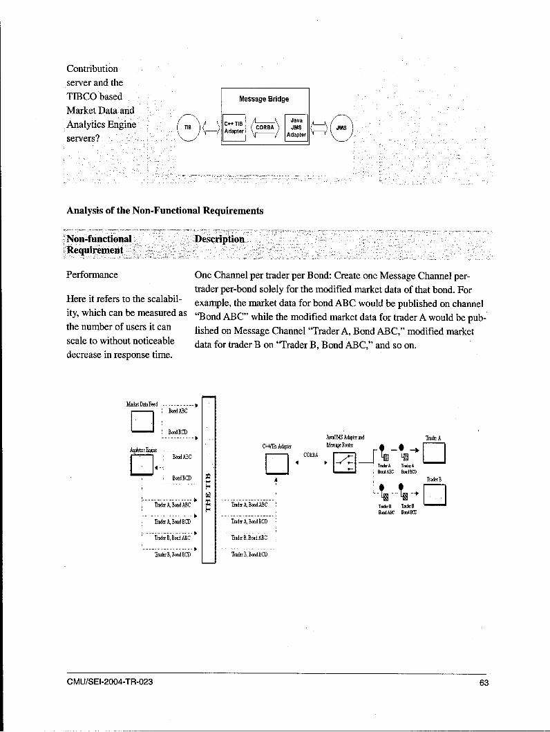
Contributionserver and theTIBCO based Message Bridge
Market Data andAnalytics Engine TI13 (A C- TIE CA---
Analtics\-F AdaterAdapterservers? -_
Analysis of the Non-Functional Requirements
Non-functional DescriptionRequirement
Performance One Channel per trader per Bond: Create one Message Channel per-trader per-bond solely for the modified market data of that bond. For
Here it refers to the scalabil- example, the market data for bond ABC would be published on channelity, which can be measured as "Bond ABC" while the modified market data for trader A would be pub-the number of users it can lished on Message Channel "Trader A, Bond ABC," modified marketscale to without noticeable data for trader B on "Trader B, Bond ABC," and so on.decrease in response time.
MmketDataFeed---------BontdABC
--]- BondBCD D-- -------- J a na f l M S A d a p ten a n d T r a d e r A
.Aabca C++ Adapter MessageRouter
[] Bood ABC iiRB Li4 -A Trade:A
BondBCD l TraderB
TraderA, Bond ABC --- Tra-derr. Bon-d-A-BC TredeB TrIr1`Bo~dABC BmM~f
TraderA,BondBCD Trader A,Bond BCD
TradtrB.BoadABC Trader B.BondABC
TraderB, Bond BCD TramdtB, Bond BCD
CMU/SEI-2004-TR-023 63
Cost Effort: 47 person-months for developing the integration components
(Refer to Appendix C: Trading Bond COCOTS Estimation Details.)Custom development effortfor integration
Hardware/Software Below are the hardware and software requirements regarding compo-
Requirements nents.
I. Analytic Engine and Contribution Server
a. a high-end server class machine with minimum of 512 Mb ofRAM
b. Windows 2000 server
2. Traders Desktop Machine (Client):
a. Windows NT, Solaris
b. 128 MB of RAMc. Java Virtual Machine
3. TIBCO Information BUS Messaging infrastructure
4. Market Data Price Feed Server
Impacts/Change Analysis on Architecture
The high-level architecture of the system is represented in Figure 10.
64 CMU/SEI-2004-TR-023

Pricing ThickClient Contribution,ateway lnt Gateway
Java .--- Java
C++ C++
C-++ Pricing ContributionGateway I Gateway
The Contributiont ...Server
AnalyticsEngine Markt DataTrading
____________Venues
Figure 10: Logical View of the System
1. TIBCO Information Bus Messaging infrastructure has been selected to achieve three-way com-munications between Market Data Feed Server, Analytics Engine and Pricing Gateway as shownin Figure 10.
2. Two Java Gateways are used to provide communication between the Market Data Feed Serverand the Trading Venues:
a. Pricing Gateway for Market Data Feed Serverb. Contribution Server for sending prices to Trader Venues
3. Message Bridge is used to provide communication between JMS used to provide communicationbetween Pricing and Contribution Gateways and TIB (TIBCO Information Bus). This messagebridge has C++ and Java Adapters and these adapters communicate with each other throughCORBA.
Constraints and Assumptions Made about the Components1. The system inherits C++ legacy components namely: Market Data Feed Server and Contribution
Server.
2. The system also uses TIBCO Information Bus Messaging Infrastructure as a third-party component.
3. The traders' venue desktop can run on Windows NT or Solaris Operating System.
CMU/SEI-2004-TR-023 65

Step 3: List the integration mechanisms which are the classification parameters and categorize
them into primitive classification types.
Categorization of Classification Parameters
Integration Patterns (Primitive Classification Primitive Classification TypeType Parameters)
Legacy Translator (Java thick Client talking with Legacy IntegrationC++ Legacy Servers)
Gateways Application Integration
Messaging (JMS) Middleware Integration
Publish and Subscribe Channel Middleware Integration
Messaging Bridge Application Integration
Channel Bridge Application Integration
Communication Vehicle between Adapters Application Integration
From this table we can infer that the current scenario is a composite of three primitive classificationtypes, namely
"* Legacy Integration
"* Application Integration
"* Middleware Integration
Step 4: Identify the rapid integration tools needed to quickly solve this problem.
In this step we try to represent the scenario as a set of classification parameters. Here we have theintegration mechanisms that serve as the classification parameters.
Mathematically, scenario can be expressed as
Scenariol = {Legacy Translator, Gateways, Messaging (JMS), Publish & Subscribe Channel, Mes-saging Bridge, Channel Bridge, Communication Vehicle between Adapters)
The parameters identified using this scenario form the elements of the primitive classification type.
1. Legacy Integration = { Legacy Translator}
2. Application Integration = {Gateways, Messaging Bridge, Channel Bridge, Communication Ve-hicle between Adapters)
3. Middleware Integration = IMessaging (JMS), Publish and Subscribe Channel)
66 CMU/SEI-2004-TR-023
For the current scenario the parameters assume following values:
1. Legacy Translator="Java to C++ Translator"
2. Gateways ="Java Gateways"
3. Messaging Bridge="Bridge C++ Messaging system to JAVA Messaging System"
4. Channel Bridge="C++ TIB Adapter & JMS Adapter"
5. Communication Vehicle between Adapters ="CORBA"
6. Messaging (JMS) ="IBM MQ Series"
7. Publish and Subscribe Channel="Channel for different types of pricing data with Gateways asPublisher and Clients as Subscriber"
From the analysis done to classify the rapid integration tool we determine it to be a set of the combi-nations of the primitive classification types:
RIT for Scenario = { Legacy, Application, Middleware}
Similarly when we generalize it
RIT for Scenario, = {Primitive Classification Type *
Step 5: Select tools.
Through use of the Tool Classification Matrix the following tools are identified to support this inte-gration.
1. Microsoft BizTalk Server
2. IBM WebSphere
3. Pervasive Data Junction
CMU/SEI-2004-TR-023 67

Tools Classification Matrix
Name of the Tool Classification based on Primitive Integration Types
RogueWave's LEIF • :i ,, :,
IBM Rational Rapid Developer ., :r'•••-'
Microsoft SQL Server , ':
Host Integration Server...-• : i ,
Microsoft BizTalk ServerIBM WebSphere Business Integration
Artix Relay pid'Developer
Artix Encompass
Artix Mainframe
PiiE Smart Client
PiiE Fusion Server
InterSystem Ensemble
Jboss
68 CMU/SEI-2004-TR-023

Appendix D Commercial Off-the-ShelfComponents
This section describes the Customized Dukascopy Data Feed Components (CDDF).http://www.dukascopy.com/english/ddfmain/rdata/
Java Feeder Component:The Feeder components are commercial off-the-shelf (COTS) products provided by Dukascopy.These components connect themselves to Dukascopy Market Machine data source and supply dataevery 10 seconds to the software application connected to it. Dukascopy Market Machine data sourcesupplies data on liquid trading instruments.
The data has the following format:stockld - integerValue - doubletickVolume - integer (on every instrument)
where
stocklD is the ID of trading instrument set by the userValue is an average 10 sec price value.
Besides providing real-time data, this component can also transfer historical data going back threedays (nearly 22000 of 10 sec ticks) that can be used to fill in occasional gaps in the database.
Component Specification:
The Feeder component provides interfaces and methods listed below. These can be used by the appli-cation program to capture the data collected by this component from Dukascopy Market Machinedata source:
1. DataListener Interface
onNewTick(int id, double value, int volume): This method provides the data that is fetchedfrom the Dukascopy Market Machine data source.
2. TickerListener Interface
a. onNewTick(int id, double value, int volume): This method provides the data that is fetchedfrom the Dukascopy Market Machine data source.
b. onNewConnection(Connector conn)
3. addQuote(int id, String code) method in FeederConnector Class: This method allows the applica-tion program to add a specific trading instrument for which the data has to be collected.
4. removeQuote(String code) method in FeederConnector Class: This method allows the applica-tion program to remove a specific trading instrument for which the data has to be collected.
CMU/SEI-2004-TR-023 69
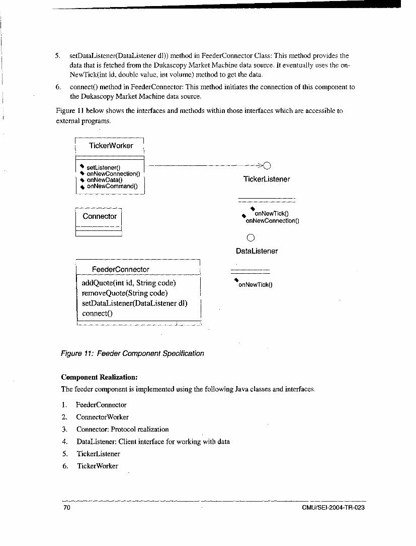
5. setDataListener(DataListener dl)) method in FeederConnector Class: This method provides thedata that is fetched from the Dukascopy Market Machine data source. It eventually uses the on-NewTick(int id, double value, int volume) method to get the data.
6. connecto method in FeederConnector: This method initiates the connection of this component tothe Dukascopy Market Machine data source.
Figure 11 below shows the interfaces and methods within those interfaces which are accessible toexternal programs.
TickerWorker
4setListener0 >04onNewConnection04onNewData0 TickerListener
SonNewCommand0
Connector o onNewTickOonNewConnection0
0DataListener
FeederConnector
addQuote(int id, String code) 4 onNewTickoremoveQuote(String code)setDataListener(DataListener dl)connect()
Figure 11: Feeder Component Specification
Component Realization:
The feeder component is implemented using the following Java classes and interfaces.
1. FeederConnector
2. ConnectorWorker
3. Connector: Protocol realization
4. DataListener: Client interface for working with data
5. TickerListener
6. TickerWorker
70 CMU/SEI-2004-TR-023

TickerListener 1 0
TickerListener
SConnector
ConnectorWorker
SDataListener : 0
DataListener
STickerWorker
VC++ MarketDataFeed Component:
The following are the VC++ files that define the responsibility of the VC++ Component:
1. CConn.vcproj
This is the main project file for VC++ projects generated using an Application Wizard. It con-tains information about the version of Visual C++ that generated the file and information aboutthe platforms, configurations, and project features selected with the Application Wizard.
2. CConn.idl
This file contains the IDL definitions of the type library, the interfaces and co-classes defined inthe project. This file will be processed by the MIDL compiler to generate
C++ interface definitions and GUID declarations (CConn.h)
3. CCoCConn.vcproj
This is the main project file for VC++ projects generated using an Application Wizard. It con-tains information about the version of Visual C++ that generated the file, and information aboutthe platforms, configurations, and project features selected with the Application Wizard.
4. CConn.idl
This file contains the IDL definitions of the type library, the interfaces and co-classes defined in
the project.
CMU/SEI-2004-TR-023 71
This file will be processed by the MIDL compiler to generate the following:
C++ interface definitions and (CConn.h)
GUID declarations
GUID definitions (CConn-i.c)
A type library (CConn.tlb)
Marshaling code (CConn-p.c and dlldata.c)
5. CConn.h
This file contains the C++ interface definitions and GUID declarations of the items defined in
CConn.idl. It will be regenerated by MIDL during compilation.
6. CConn.cpp
This file contains the object map and the implementation of your DLL's exports.
7. CConn.rc
This is a listing of all of the Microsoft Windows resources that the program uses.
8. CConn.def
This module-definition file provides the linker with information about the exports required bythe DLL. It contains exports for
DliGetClassObjectDllCanUnloadNowGetProxyDllInfoDllRegisterServerDilUnregisterServer
Other standard files
9. StdAfx.h, StdAfx.cpp
These files are used to build a precompiled header (PCH) file named CConn.pch and a precom-piled types file named StdAfx.obj.
10. Resource.h
This is the standard header file that defines resource IDs: Proxy/stub DLL project and moduledefinition file.
11. CConnps.vcproj
This file is the project file for building a proxy/stub DLL if necessary.
The IDL file in the main project must contain at least one interface and you must first compilethe IDL file before building the proxy/stub DLL. This process generates dlldata.c, CConn_i.c
and CConn-p.c , which are required to build the proxy/stub DLL.
72 CMU/SEI-2004-TR-023
12. CConnps.def
This module definition file provides the linker with information about the exports required bythe proxy/stub.
Other notes:
The MFC Support option builds the Microsoft Foundation Class libraries into your skeleton applica-tion, making MFC classes, objects and functions available to you.
Issues1. If the client process is not killed properly, the Java component will still deliver the data to the
client application. This state prevents the client application from re-establishing the lost connec-tion to properly terminate the data stream.
CMU/SEI-2004-TR-023 73
74 CMU/SEI-2004-TR-023
Appendix E Trading Bond System COCOTSEstimation Details
The approach followed is strictly based on the COCOTS estimation model proposed by ChristopherM. Abts and Barry W. Boehm [Abst 00]. The standard COCOTS calibration tables are used for thecalibrated parameter values for each cost driver in the model. The corresponding parameter value foreach driver is fed into the spreadsheet tooI-COCOTS calculator.
Assumptions1. Thevalues of very high, low, and so forth, have been determined based on a heuristic approach
rather than on previous data collection.
2. The KSLOC is assumed to be based on the programming experience of the team with the priorknowledge of the domain addressed here. The SLOC for developing a glue code for integratingthe C++ and Java Components using JNI is found to be approximately 1000 SLOC [1 KSLOC].
The component that is the glue code for the integrating C++ and Java is assumed to be devel-oped using JNI. We realize that the excerpts taken from the article on Junc++ion(http://www.codemesh.com/en/CodemeshWhitepaper.pdf) demonstrate that JNI requires a hugenumber of lines of code.
"If the programmer were trying to write an application to display a Java Swing dialogbox from C++ and store the user's input in C++ using JNI to communicate betweenC++ and Java, about 200 lines of JNI code would be required."
3. Since there are no real-world customers, there is a very minimal requirement change for this in-tegration scenario and hence the BRAK % is assumed to be 1.
4. The Normal Labor Cost here refers to the Software Engineers in any company that will be in-volved in the development.
Constraints
Currently, we have one option for C++ and Java components. Also, the Trading Bond System hereaddressed is restricted to the legacy integration of components
Cost Drivers Selection
The following table presents the values selected and the reasons for their selection for the various costdrivers of the COCOTS estimation model.
CMU/SEI-2004-TR-023 75

Category ,Cost Drivers, Value Why?
Integration Personal Drivers
COTS Integrator Ex- VL Two months of experience with the productsperience with Product
2 COTS Integrator Per- L Two months of experience with the domain
sonnel Capability
3 Integrator Experience L Organizational level [Professional Development Cen-with COTS Integration ter] process for COTS integration is not defined.
Processes
4 Integrator Personnel N There will be a rotation of people every year in the
Continuity Professional Development Center, as it is an educa-
tional environment.
COTS Component Drivers
1 COTS Product Maturity H The product has high time on market.
2 COTS Supplier Product L The products we consider here are standard C++ and
Extension Willingness Java components available on the net; hence the num-ber and nature of changes are very minimal.
3 COTS Product Interface N Since most of the APIs of the components are well de-
Complexity fined, consistently applied, and clear, they can easilybe used to interface with the glue code.
4 COTS Supplier Product H The level of available support is high; a detailed ex-Support planation of the components to be integrated is
available.
5 COTS Supplier Pro- N Nominal documentation is provided for the scenariovided Training and considered here.Documentation
6 COTS Product Volatility L Only one release is expected.
76 CMU/SEI-2004-TR-023

Application/System Drivers
I Constraints on N This is not a mission-critical system; there are backup
System/Subsystem servers to recover the lost data.Reliability
2 Application Interface L Use of standard communication mechanisms such as
Complexity. APIs reduces the application interface complexity.
3 Constraints on VH The analytic engine handles the real-time market dataSystem/Subsystem and feeds it to trader's desktop.
Technical Performance
4 System Portability VH The traders' desktops might be running on different
operating systems.
Nonlinear Scale Factor
1 Application Architec- L Simple paper Analysis of the architecture of the systemtural Engineering will be done for the currently selected scenario.
CMU/SEI-2004-TR-023 77

- C\l
Cý0
C/)
It 0 Cý
0---
00
j 0 0 - 0
q - oq r--
N 00 0
knN C) 0
O00 110 C) c
0 C0
en -, 000 r
r- \0
4.40
"00 "0- ~ ~ C - 00
QD'- 4 - z
o _____o
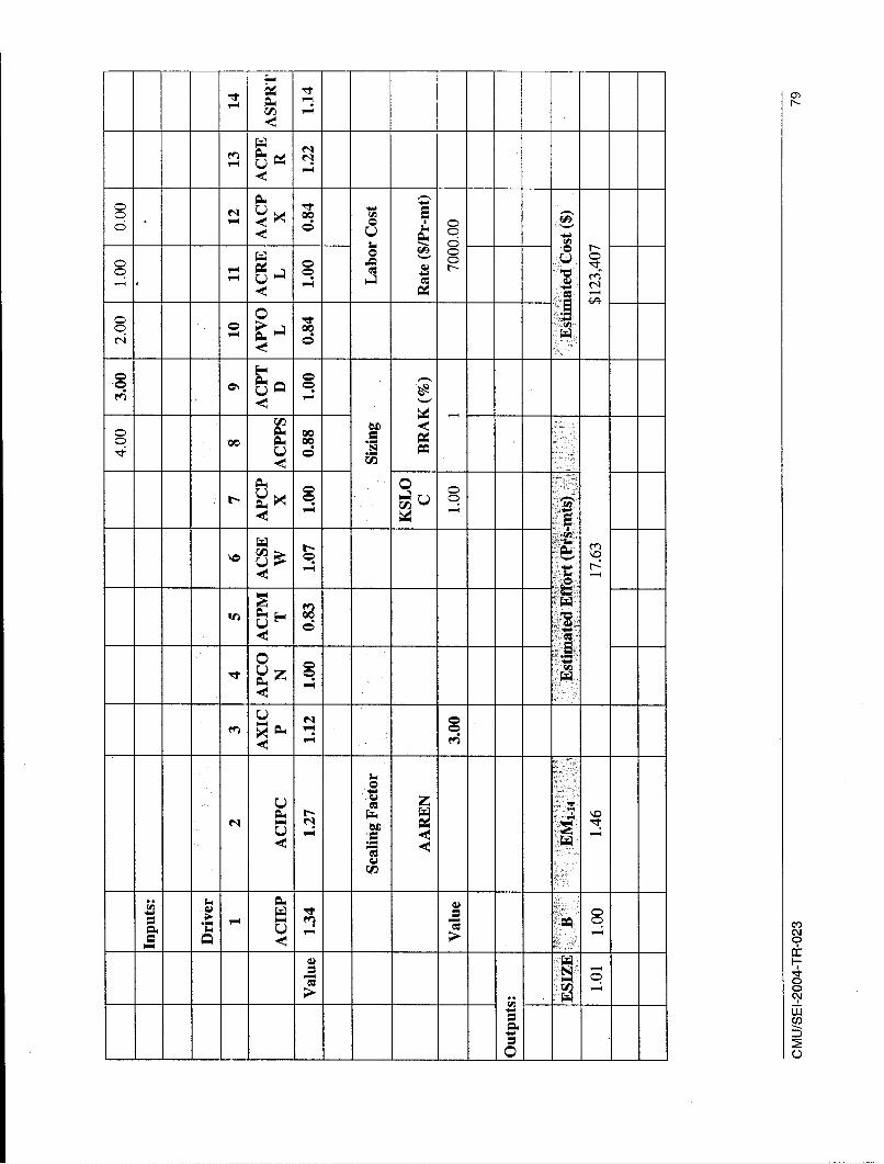
00)
c,0 -O
U
u0c
0n 0ou
C -~ 0
0u0 e4
-;
U)f
-4C~09
C0)
C?
0
CM
uLJ
C')
00
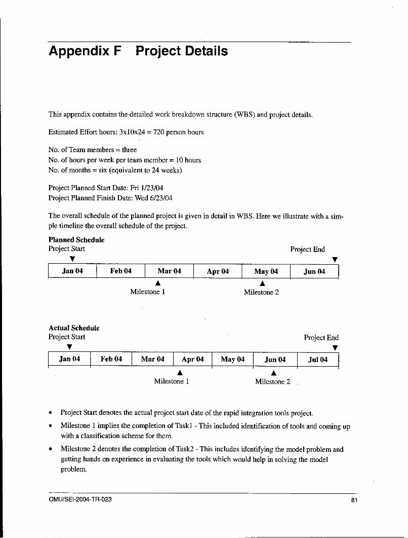
Appendix F Project Details
This appendix contains the detailed work breakdown structure (WBS) and project details.
Estimated Effort hours: 3x10x24 = 720 person hours
No. of Team members = threeNo. of hours per week per team member = 10 hoursNo. of months = six (equivalent to 24 weeks)
Project Planned Start Date: Fri 1/23/04Project Planned Finish Date: Wed 6/23/04
The overall schedule of the planned project is given in detail in WBS. Here we illustrate with a sim-ple timeline the overall schedule of the project.
Planned ScheduleProject Start Project End
V VJan 04 Feb 04 Mar 04 Apr 04 May 04 Jun04
A AMilestone 1 Milestone 2
Actual ScheduleProject Start Project End
V VJan 04 Feb 04 1 Mar 04 Apr 04 May 04 Jun 04 Jul 04
A AMilestone 1 Milestone 2
* Project Start denotes the actual project start date of the rapid integration tools project.
* Milestone 1 implies the completion of Task 1 - This included identification of tools and coming upwith a classification scheme for them.
Milestone 2 denotes the completion of Task2 - This includes identifying the model problem andgetting hands on experience in evaluating the tools which would help in solving the modelproblem.
CMU/SEI-2004-TR-023 81

0 Project End denotes the submission of the evaluation results in the form of a technical report and
expressing the process of evaluation as a framework that can be extended to any model problem.
The line in the actual schedule denotes where we were when we were writing this technical report.
Similarly, the estimated effort into the project also increased from 720 person hours to 840 person
hours.
Estimation:
The above WBS is based on the rapid integration tools document provided by the SEI before the start
of the project. The project is divided into three tasks which have deliverables associated with each of
them. The milestones are based completely on the three tasks. Each Task was allocated two months
out of the total six months for the project.
Actual Progress:
However, as shown in the actual progress timeline, Task 1 took almost three months for completion,
Task 2 took another three months to complete, and Task 3 is currently underway at the time of writing
this report.
The primary reasons for schedule slippage are multiple commitments of team members on other pro-
jects, and the fewer number of hours allocated for the elective.
Table 8: Milestones and Schedule of the Project
Milestones Expected Date Revised Date of Actual Date ofSubmission Submission
Task 1 - Survey and clas- 2/5/2004 6/7/2004 5/18/2004
sify the tools-
"* List of Rapid Integra-
tion Tools
"* Classification Scheme 2/17/2004 6/09/2004 6/5/2004
"* Classified List of 3/02/2004 6/10/2004 6/5/2004
Tools
Task 2 - Evaluate the' tools 3/19/2004 6/16/2004
using a model problem
"* Preliminary Evalua-tion Scheme
"* Model Problem Defi- 4/26/2004 6/16/2004 5/18/2004
nition
82 CMU/SEI-2004-TR-023

Reports detailing 5/11/2004 6/24/2004 5/18/2004evaluation of tools'applicability to the
model problem
Task 3 - Develop and 6/1/2004 5/28/2004
document general evalua-tion criteria
Documented evalua-tion criteria for rapidintegration tools
CMU/SEI-2004-TR-023 83

84 CMU/SEI-2004-TR-023
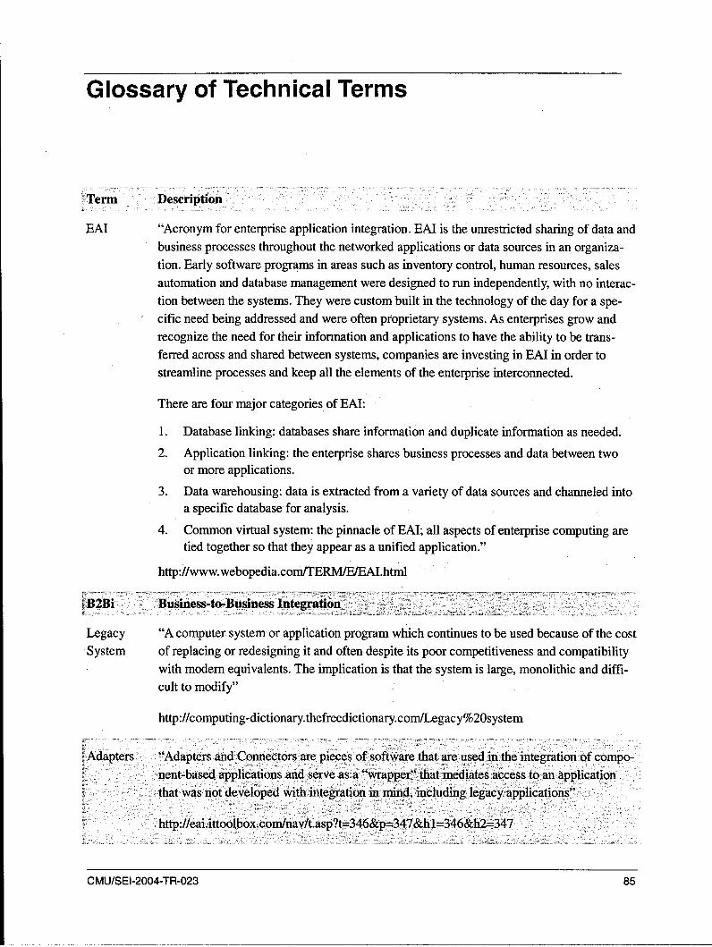
Glossary of Technical Terms
-,T~erm Description
EAI "Acronym for enterprise application integration. EAI is the unrestricted sharing of data and
business processes throughout the networked applications or data sources in an organiza-
tion. Early software programs in areas such as inventory control, human resources, sales
automation and database management were designed to run independently, with no interac-
tion between the systems. They were custom built in the technology of the day for a spe-
cific need being addressed and were often proprietary systems. As enterprises grow and
recognize the need for their information and applications to have the ability to be trans-
ferred across and shared between systems, companies are investing in EAI in order to
streamline processes and keep all the elements of the enterprise interconnected.
There are four major categories of EAI:
1. Database linking: databases share information and duplicate information as needed.
2. Application linking: the enterprise shares business processes and data between two
or more applications.
3. Data warehousing: data is extracted from a variety of data sources and channeled into
a specific database for analysis.
4. Common virtual system: the pinnacle of EAI; all aspects of enterprise computing are
tied together so that they appear as a unified application."
http://www.webopedia.com/TERM/E/EAI.html
B2Bi Business-to-Business Integratio on
Legacy "A computer. system or application program which continues to be used because of the cost
System of replacing or redesigning it and often despite its poor competitiveness and compatibility
with modem equivalents. The implication is that the system is large, monolithic and diffi-
cult to modify"
http://computing-dictionary.thefreedictionary.com/Legacy%20system
Adapters "Adapters and Connectors are pieces of software that are used in the integration of compo-nent-based applications and serve as a "wrapper" thatmediates access to an application
that was not developed with integration in mind, including legacy applications"
http://ea3.ittoolbox.con3nav/t.asp?t=346&p =347&h1=346&h2=347
CMU/SEI-2004-TR-023 85

Service- "Service-Oriented Integration (SOI) leverages open standards, loose coupling, and dy-
Oriented namic description and discovery capabilities of Web Services to reduce the complexity,Integration cost, and risk of integration."
http://www.zapthink.com/cluster.html?id=soi
Web Ser- "Web Services refers to the technologies that allow for making connections. Services arevices what you connect together using Web Services. A service is the endpoint of a connection.
Also, a service has some type of underlying computer system that supports the connectionoffered. The combination of services-internal and external to an organization-make up a'service-oriented architecture."
.http:/www.service-architecture.com/web-services/articles/web-services-defmition.html
ALE Stands for Application Embedding and Linking. "ALE allows behaviors between compo-
nents and applications to be linked on a single-screen. Users are able to drill within appli-cations, as well as from one application to another, without changing focus.
ALE overcomes the limitations of HTML-based Web applications where any embeddedlink typically brings up a new page with no contextual link between the various Webpages."
http://www.dharbor.com/products/psc-feat.html
JMX "Java Management Extensions (JMX) technology provides the tools for building distrib-
uted, Web-based, modular and dynamic solutions for managing and monitoring devices,papplications, and service-driven networks. By design, this standard is suitable for adapting
legacy systems, implementing new management and monitoring solutions, and plugging
into those of the future"
"http://java.sun.conm/products/JavaManagement/
CICS "Short for Customer Information Control System, a TP monitor from IBM that was origi-nally developed to provide transaction processing for IBM mainframes. It controls the in-
teraction between applications and users and lets programmers develop screen displays
without detailed knowledge of the terminals being used."
http://www.webopedia.com/TERM/C/CICS.html
SOAP '",Short for Simple Object Access Protocol, a lightweight XML-based messaging protocol
usedto eficode the information in Web service request and response messages before send-
ing them over a network.
SOAP messages are independent of any operating system or protocol and may be trans-
86 CMU/SEI-2004-TR-023
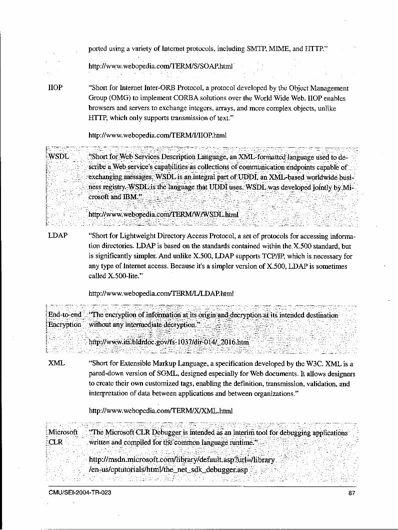
ported using a variety of Internet protocols, including SMTP, MIME, and HTTP."
http://www.webopedia.com/TERMISISOAP.html
HOP "Short for Internet Inter-ORB Protocol, a protocol developed by the Object ManagementGroup (OMG) to implement CORBA solutions over the World Wide Web. HOP enablesbrowsers and servers to exchange integers, arrays, and more complex objects, unlikeHTTP, which only supports transmission of text."
http://www.webopedia.com/TERM/J/IIOP.html
WSDL "Short for Web Services Description Language, an XML-forniatted language used to de-scribe a Web service's capabilities as collections of communication endpoints capable ofexchanging messages. WSDL is an integral part of UDDI, an XML-based worldwide busi-,ness registry. WSDL is the language that UDDI uses. WSDL was developed jointly by Mi-crosoft and IBM."
http://www.webopedia.com/TERMIW/WSDL.html
LDAP "Short for Lightweight Directory Access Protocol, a set of protocols for accessing informa-tion directories. LDAP is based on the standards contained within theX.500 standard, butis significantly simpler. And unlike X.500, LDAP supports TCP/IP, which is necessary forany type of Internet access. Because it's a simpler version of X.500, LDAP is sometimescalled X.500-lite."
http://www.webopedia.com/TERM/LILDAP.html
•'End-to-end 'The encryption of information at its origin and decryption at its intended destination
LEncryption without any intermediate decryption."
http://www.its.bldrdoc.gov/fs-1037/dir-014/_2016.htm
XML "Short for Extensible Markup Language, a specification developed by the W3C. XML is apared-down version of SGML, designed especially for Web documents. It allows designersto create their own customized tags, enabling the definition, transmission, validation, andinterpretation of data between applications and between organizations."
http://www.webopedia.com/TERM/X/XML.html
Microsoft '•he Microsoft CLR Debugger is intended as an interim tool for debugging applicationsCLR written and compiled for the common language runtime."
http://msdn.microsoft.conllibrary/default.asp?url=/iibrary/en-us/cptutorials/html/the net sdkdebugger.asp
CMU/SEI-2004-TR-023 87
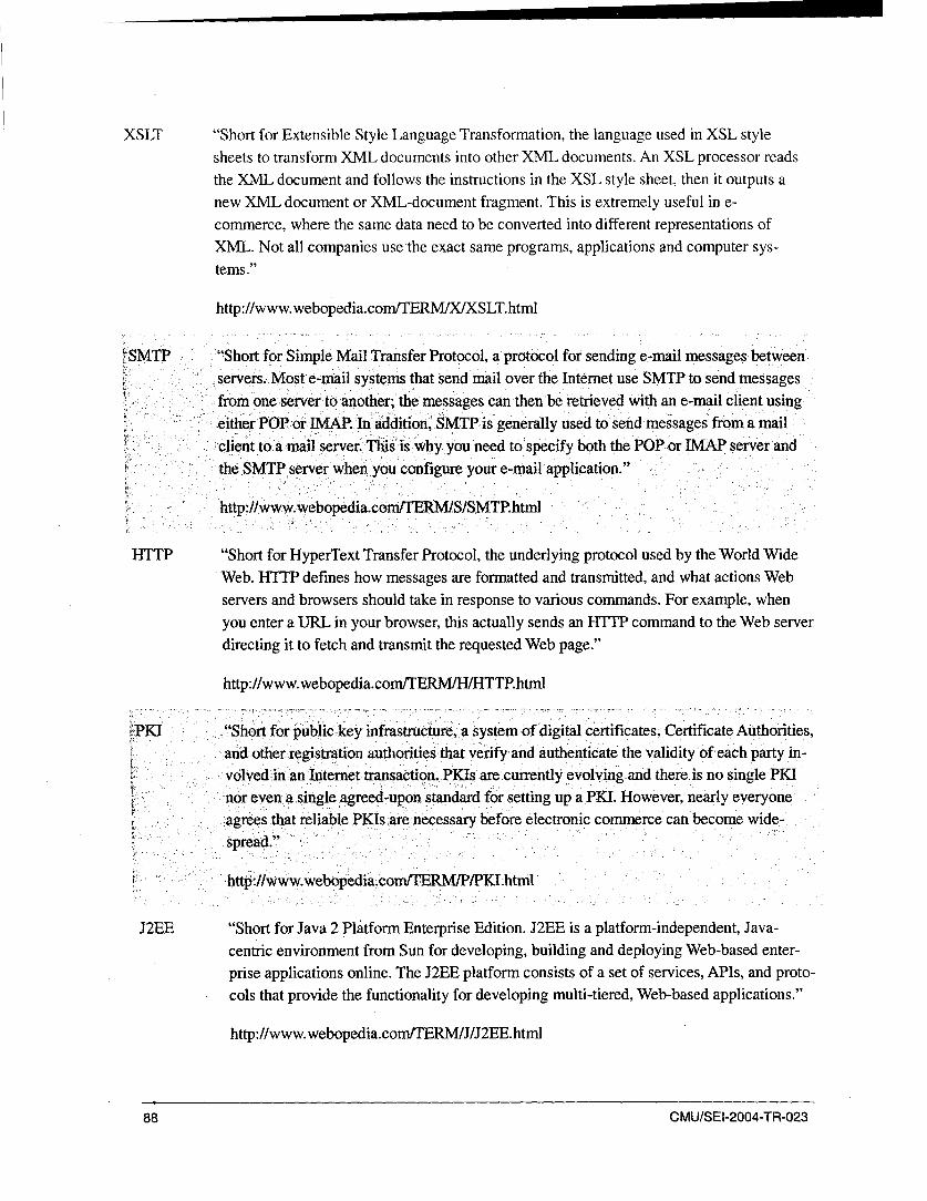
XSLT "Short for Extensible Style Language Transformation, the language used in XSL stylesheets to transform XML documents into other XML documents. An XSL processor readsthe XML document and follows the instructions in the XSL style sheet, then it outputs a
new XML document or XML-document fragment. This is extremely useful in e-commerce, where the same data need to be converted into different representations ofXML. Not all companies use the exact same programs, applications and computer sys-tems."
http://www. webopedia.com/TERM/X/XSLT.html
'SMTP "Short for Simple Mail Transfer Protocol, a protocol for sending e-mail messages between
servers. Most e-mail systems that send mail over the Internet use SMTP to send messages
from one server to another; the messages can then be retrieved with an e-mail client using"either POP or IMAP. In addition, SMTP is generally used to send messages from a mail
client to a mail server. This"is why you need to specify both the POP or JIMAP server andthe SMTP server when you configure your e-mail application."
http:l/www, webopeldia.com/TERMISISMTP.html
HTTP "Short for HyperText Transfer Protocol, the underlying protocol used by the World WideWeb. HTTP defines how messages are formatted and transmitted, and what actions Webservers and browsers should take in response to various commands. For example, whenyou enter a URL in your browser, this actually sends an HTTP command to the Web serverdirecting it to fetch and transmit the requested Web page."
http://www.webopedia.com/TERMIH/HTTP.htmil
PMI "Short for public key infrastructure, a system of digital certificates, Certificate Authorities,and other registration authorities that verify and authenticate the validity of each party in-volved in an Internet transaction. PKIs are currently evolving and there is no single PKInorrevena single agreed-upon standard fOr setting up aPKI. However, nearly everyone,agrees that reliable PKIs are necessary before electronic commerce can become wide-'spread."
http://www.webopedia.com/TERM/P/PKI.htmln-
J2EE "Short for Java 2 Platform Enterprise Edition. J2EE is a platform-independent, Java-
centric environment from Sun for developing, building and deploying Web-based enter-
prise applications online. The J2EE platform consists of a set of services, APIs, and proto-
cols that provide the functionality for developing multi-tiered, Web-based applications."
http://www.webopedia.com/TERMIJ/J2EE.htmi
88 CMUISEI-2004-TR-023

JSP "Short for Java Server Page. A server-side technology, Java Server Pages are an extensionto the Java servlet technology that was developed by Sun. JSPs have dynamic scriptingcapability that works in tandem with HTML code, separating the page logic from the staticelements -- the actual design and display of the page-to help make the HTML more func-tional (i.e., dynamic database queries)."
http://www webopedia.com/TERMIJ/JSP.html
JCA "The J2EE Connector architecture provides a Java technology solution to the problem ofconnectivity between the many application servers and today's enterprise information sys-tems (EIS)."
http://java.sun.com/j2ee/connector/overview.html
EJB "Enterprise JavaBeans (EJB) is a Java API developed by Sun Microsystems that definescomponent architecture for multi-tier client/server systems. EFB systems allow developersto focus on the actual business architecture of the model, rather than worry about endlessamounts of programming and coding needed to connect all the working parts. This task isleft to EJB server vendors. Developers just design (or purchase) the needed EJB compo-nents and arrange them on the server."
http:/lwww.webopedia.conVTERNIE/EnterpriseJavaBeans.html
JAAS "The Java Authentication and Authorization Service (JAAS) is a set of APIs that enableservices to authenticate and enforce access controls upon users. It implements a Java tech-nology version of the standard Pluggable Authentication Module (PAM) framework, andsupports user-based authorization."
http://java.sun.com/products/jaas/
* Aspect Ori- "Aspect-oriented programming (AOP) is a new programming technique that allows pro-ented Pro- grammers to modularize crosscutting concerns (behavior that cuts across the typical divi-gramming sions of responsibility, such as logging). AOP introduces aspects, which encapsulate be-
haviors that affect multiple classes into reusable modules."
http://www-106.ibm.comldeveloperworks/java/library/j-aspectj/
CMU/SEI-2004-TR-023 89

90 CMU/SEI-2004-TR-023

References/Bibliography
URLs are valid as of the publication date of this document.
[Abst 00] Abst, C.; Boehm, B.; & Clark, B. COCOTS: A Software IntegrationCost Model. Los Angeles, CA: USC Center for Software Engineer-ing 2000. http://sunset.usc.edu/publications/TECHRPTS/2000 /usccse2000-501/usccse2000-501.pdf
[Brownsword 04] Brownsword, L.; Carney, D. J.; Fisher, D.; Lewis, G.; Meyers, C.;Morris, E. J.; Place, R. H.; Smith, J.; & Wrage, L. Current Perspec-tives on Interoperability (CMU/SEI-2004-TR-009, ADA421613).Pittsburgh, PA: Software Engineering Institute, Carnegie MellonUniversity, 2004. http://www.sei.cmu.edu/publications/documents/04.reports/04tr009.html
[IONA 02] ONA Technologies PLC. IONA s Orbix E2A Enterprise Integration
Technology. Waltham, MA: IONA Technologies PLC, 2002.
[Jaccheri 02] Jaccheri, L. & Torchiano, M. "Classifying COTS Products," 246-255. Software Quality - ECSQ 2002. Quality Connection - 7thEuropean Conference on Software Quality. Helsinki, Finland, June9-13, 2002. Proceedings, Lecture Notes in Computer Science, 2349.Berlin, Germany: Springer-Verlag, 2002.
[Johnson 88] Johnson, A. M. & Malek, M. "Survey of Software Tools for Evaluat-ing Reliability, Availability, and Serviceability." Computing Surveys,20, 4, (Dec. 1988) 227-269.
[Kasunic 03] Kasunic, Mark. "Measuring Systems Interoperability." Conferenceon the Acquisition of Software-Intensive-Systems. Arlington, VA,January 28-30, 2003. Pittsburgh, PA: Software Engineering Insti-tute, Carnegie Mellon University 2003.
[Ncube 02] Ncube, C. & Dean, J. "Limitations of Current Decision-MakingTechniques in the Procurement of COTS Software Components,"176-187. Proceedings of the First International Conference ofCOTS-Based Software Systems, ICCBSS 2002. Orlando, FL, Febru-ary 4-6, 2002. Berlin, Germany: Springer-Verlag, 2002.
CMU/SEI-2004-TR-023 91
[Powell 97] Powell, A., et al. "Evaluating Tools to Support Component BasedSoftware Engineering, 80-89. Proceedings of the Fifth InternationalSymposium on Assessment of Software Tools and Technologies.Pittsburgh, PA, June 2-5, 1997. Los Alamitos, CA: IEEE ComputerSociety Press, 1997.
[Sai 04] Vijay, S. COTS Acquisition Evaluation Process: Preacher's Practice(CMU/SEI-2004-TN-001, ADA421675). Pittsburgh, PA: Software Engi-neering Institute, Carnegie Mellon University, 2004.http://www.sei.cmu.edu/publications/documents /04.reports/04tn001.html
[Schmidt 02] Schmidt, Marty. J. Business Case Essentials: A Guide to Structure andContent. West Sussex, UK: Matrix Solutions Ltd, 2002.http://www.eitoolkit.com/tools/initiation /BusinessCaseEssentials.pdf
[Simon 03] Simon, Jonathan. "Case Study: Bond Trading System." Chapter 13, Hohpe,Gregor & Woolf, Bobby. Enterprise Integration Patterns. Boston, MA:Addison-Wesley, 2004.
[Vu 02] Vu, John. "The eCommerce Capability Model (eCCM): A Framework ToImplement eCommerce Successfully."(tutorial). SEPG 2000: Software En-gineering Process Group Conference, Phoenix, AZ, February 18-21, 2002.
[Wallnau 91] Wallnau, K. & Feiler, P. Tool Integration and Environment Architectures(CMU/SEI-91-TR-0 11, ADA2378 10). Pittsburgh, PA: Software Engineer-ing Institute, Carnegie Mellon University, 1991.http://www.sei.cmu.edu/publications/documents /91 .reports /91.tr.011.html
[Wallnau 02] Wallnau, K.; Hissam, S.; & Seacord, R. Building Systems from CommercialComponents. Boston, MA: Addison Wesley, 2002.
92 CMU/SEI-2004-TR-023

REPORT DOCUMENTATION PAGE Form ApprovedOMB No. 0704-0188
Public reporting burden for this collection of information is estimated to average 1 hour per response, including the time for reviewing instructions, searchingexisting data sources, gathering and maintaining the data needed, and completing and reviewing the collection of information. Send comments regardingthis burden estimate or any other aspect of this collection of information, including suggestions for reducing this burden, to Washington HeadquartersServices, Directorate for information Operations and Reports, 1215 Jefferson Davis Highway, Suite 1204, Arlington, VA 22202-4302, and to the Office ofManagement and Budget, Paperwork Reduction Project (0704-0188), Washington, DC 20503.
1. AGENCY USE ONLY 2. REPORTDATE 3. REPORTTYPEANDDATESCOVERED
(Leave Blank) December 2004 Final
4. TITLE AND SUBTITLE 5. FUNDING NUMBERS
Rapid Integration for Rapid Application Development F1 9628-00-C-0003
6. AUTHOR(S)
Amit Midha, Ravindra Singh, Lakshmi Pratha Hari7. PERFORMING ORGANIZATION NAME(S) AND ADDRESS(ES) 8. PERFORMING ORGANIZATION
Software Engineering Institute REPORT NUMBER
Carnegie Mellon University CMU/SEI-2004-TR-023Pittsburgh, PA 15213
9. SPONSORINGIMONITORING AGENCY NAME(S) AND ADDRESS(ES) 10. SPONSORINGWMONITORING AGENCY REPORT
HO ESC/XPK NUMBER
5 Eglin Street ESC-TR-2004-023Hanscom AFB, MA 01731-2116
11. SUPPLEMENTARY NOTES
12A DISTRIBUTIONIAVAILABILITY STATEMENT 12B DISTRIBUTION CODE
Unclassified/Unlimited, DTIC, NTIS13. ABSTRACT (MAXIMUM 200 WORDS)
This report investigates the rapid integration tools available in the current market. These tools aid in the rapidintegration of software systems and components. The research centers on a model problem that requiressuch a tool to address legacy integration challenges. The report presents a generic evaluation framework foridentifying and evaluating rapid integration tools and an evaluation of three identified tools. This evaluationengaged selected evaluation criteria based on the demands of the model problem. A process reference isalso included; this forms the guidelines for identification and evaluation of the tools with respect to othermodel problems.
14. SUBJECTTERMS 15. NUMBER OF PAGES
rapid integration, integration tools, rapid application development 107
16. PRICE CODE
17. SECURITY CLASSIFICATION 18. SECURITY CLASSIFICATION OF 19. SECURITY CLASSIFICATION OF 20. LIMITATION OF ABSTRACT
OF REPORT THIS PAGE ABSTRACT U LUnclassified Unclassified Unclassified
NSN 7540-01-280-5500 Standard Form 298 (Rev. 2-89) Prescrbed by ANSI Std. Z39-18 298-102