raven rate control module (rcm) operation manual
TRANSCRIPT

Copyright 2016, 2017, 2018, 2019
Raven Rate Control Module (RCM) Operation
Manual
016-0171-637 Rev. E 8/2019 E32581

016
We
Solv
e Gr
eat C
halle
nges
.
DWreinf
Ra ated be sy irs ma
As sagu to us ls or avse
ISCLAIMER hile every effort has been made to ensure the accuracy of this document, Raven Industries assumes no sponsibility for omissions and errors. Nor is any liability assumed for damages resulting from the use of ormation contained herein.
ven Industries shall not be responsible or liable for incidental or consequential damages or a loss of anticipnefits or profits, work stoppage or loss, or impairment of data arising out of the use, or inability to use, thisstem or any of its components. Raven Industries shall not be held responsible for any modifications or repade outside our facilities, nor damages resulting from inadequate maintenance of this system.
with all wireless and satellite signals, several factors may affect the availability and accuracy of wireless andtellite navigation and correction services (e.g. GPS, GNSS, SBAS, etc.). Therefore, Raven Industries cannot arantee the accuracy, integrity, continuity, or availability of these services and cannot guarantee the ability e Raven systems, or products used as components of systems, which rely upon the reception of these signaailability of these services. Raven Industries accepts no responsibility for the use of any of these signals or rvices for other than the stated purpose.
-0171-686 Rev. A 8/18 E31924

Table of Contents
Calibration Reference Sheet ................................................................................................................................. xvUnit Definitions and Conversions ..................................................................................................................... xvi
Unit of Measure Definitions ........................................................................................................................................... xviUnit of Measure Conversions ........................................................................................................................................ xvi
Chapter 1 Important Safety Information............................................................................. 1Instructions for Wire Routing .................................................................................................................................3Instructions for Hose Routing ................................................................................................................................5
Chapter 2 Introduction............................................................................................................. 7Raven Rate Control Module™ Features ..............................................................................................................7
Direct Injection ........................................................................................................................................................................ 7Machine Types ......................................................................................................................................................................... 8
Care and Use .................................................................................................................................................................9Feature Unlocks ............................................................................................................................................................9Updates ........................................................................................................................................................................ 10
Chapter 3 Liquid Operation .................................................................................................. 11Liquid Machine List ...................................................................................................................................................11Liquid Fertilizer Configuration ..............................................................................................................................11Liquid Run Page Overview .................................................................................................................................... 20
Product Tabs ...........................................................................................................................................................................20Current Product Run Screen ............................................................................................................................................20Main ...........................................................................................................................................................................................22Setup .........................................................................................................................................................................................22Totals .........................................................................................................................................................................................24Diagnostics .............................................................................................................................................................................24Auxiliary Drivers ....................................................................................................................................................................24
Chapter 4 Anhydrous Ammonia (NH3) Operation.......................................................... 27NH3 Machine List ..................................................................................................................................................... 27NH3 Configuration .................................................................................................................................................. 27NH3 Run Page Overview ....................................................................................................................................... 36
Product Tabs ...........................................................................................................................................................................36Current Product Run Screen ............................................................................................................................................36Run Page Overview ..............................................................................................................................................................36Main ...........................................................................................................................................................................................38Setup .........................................................................................................................................................................................38Totals .........................................................................................................................................................................................39Diagnostics .............................................................................................................................................................................39Auxiliary Drivers ....................................................................................................................................................................40
Chapter 5 Spreader Operation ............................................................................................. 41Spreader Machine List ............................................................................................................................................ 41Spreader Configuration ......................................................................................................................................... 44Manure/Litter Configuration ................................................................................................................................ 54
016-0171-637 Rev. E i

Table of Contents
Dynamic Calibration ............................................................................................................................................................55Density Adjustment Frequency ......................................................................................................................................55Adjustment Sensitivity .......................................................................................................................................................56Clean Out Setup ...................................................................................................................................................................56Clean out Mode ....................................................................................................................................................................56Litter/Manure Operation Tips .........................................................................................................................................57
Spreader Run Page Overview ...............................................................................................................................58Product Tabs ..........................................................................................................................................................................58Current Product Run Screen ............................................................................................................................................58Run Page Overview .............................................................................................................................................................59Main ..........................................................................................................................................................................................61Setup .........................................................................................................................................................................................61Totals .........................................................................................................................................................................................62Diagnostics .............................................................................................................................................................................62
Manure/Litter Spreader Configuration and Settings ...................................................................................62Clean Out Setup ...................................................................................................................................................................63Dynamic Calibration ............................................................................................................................................................64
Chapter 6 Air Cart Operation ............................................................................................... 65Machine Types ............................................................................................................................................................65Air Cart Configuration .............................................................................................................................................68Air Cart Run Page Overview ..................................................................................................................................79
Product Tabs ..........................................................................................................................................................................79Current Product Run Screen ............................................................................................................................................80Main ..........................................................................................................................................................................................82Setup .........................................................................................................................................................................................82Totals .........................................................................................................................................................................................83Diagnostics .............................................................................................................................................................................84Auxiliary Drivers ....................................................................................................................................................................84
Chapter 7 Planter Operation ................................................................................................ 85Planter Machine List .................................................................................................................................................85Planter Setup ...............................................................................................................................................................86
Section Controlled Planter Setup ..................................................................................................................................86Seed Rate Control with Clutches Planter Setup .......................................................................................................87Seed Rate Control without Clutches Plater Setup ...................................................................................................95
Planter Run Page Overview ................................................................................................................................104Product Tabs ....................................................................................................................................................................... 105Current Product Run Screen ......................................................................................................................................... 105Main ....................................................................................................................................................................................... 107Setup ...................................................................................................................................................................................... 107Totals ...................................................................................................................................................................................... 109Diagnostics ...........................................................................................................................................................................110Auxiliary Drivers ..................................................................................................................................................................110
Chapter 8 Stand alone Scale Operation........................................................................... 111Scale machine List ...................................................................................................................................................111Stand Alone Scale Operation ..............................................................................................................................111
ii Raven Rate Control Module (RCM) Operation Manual

Table of Contents
Scale Run Page Overview ....................................................................................................................................113Scale Screen ......................................................................................................................................................................... 113Current Product Run Screen ......................................................................................................................................... 114Main ........................................................................................................................................................................................ 115Setup ...................................................................................................................................................................................... 115Totals ...................................................................................................................................................................................... 117Diagnostics .......................................................................................................................................................................... 117Auxiliary Assignments ...................................................................................................................................................... 118
Chapter 9 Precision Farming............................................................................................... 119
Chapter 10 Troubleshooting ................................................................................................ 125Accessing System Information ..........................................................................................................................125General Troubleshooting .................................................................................................................................... 126Tests .............................................................................................................................................................................127Nozzle Flow Check .................................................................................................................................................128Rinse Cycle ................................................................................................................................................................129Control/Section Test ..............................................................................................................................................130Control Valve Test ...................................................................................................................................................130
Calibrate PWM Limits ......................................................................................................................................................131Energize System ......................................................................................................................................................131Bleed System Test ...................................................................................................................................................132Spreader/Air Cart Check ......................................................................................................................................132Bin/Tank Cleanout ..................................................................................................................................................133Demonstration Mode ...........................................................................................................................................134Diagnostic Loop back Test ..................................................................................................................................134Diagnostic LEDs .......................................................................................................................................................137Outputs Table - Multiple Products ..................................................................................................................141Inputs Table - Single Product .............................................................................................................................142Inputs Table - Multiple Product ........................................................................................................................143
Chapter 11 Diagnostics Trouble Codes.............................................................................. 145Accessing diagnostic Trouble Codes ..............................................................................................................145Diagnostic trouble codes (DTC) ........................................................................................................................145
Appendix A Calibration Values.............................................................................................. 155Section Widths ........................................................................................................................................................155Target Rate Calibration .........................................................................................................................................155
Appendix B Remote Diagnostics Application ................................................................... 157Diagnostic Mobile App ........................................................................................................................................157
Best Practices ......................................................................................................................................................................157Connect the EcU ................................................................................................................................................................157
Mobile App Screens ..............................................................................................................................................159Diagnostics ..........................................................................................................................................................................159
016-0171-637 Rev. E iii

Table of Contents
Appendix C Settings and Help Screen Terminology ........................................................ 163
iv Raven Rate Control Module (RCM) Operation Manual

CALIBRATION REFERENCE SHEETRecord settings and calibration values used when programming the system in the fields below and keep this sheet for future reference.
GENERAL IMPLEMENT INFORMATION
TANK FILL SETTINGS
PRODUCT CONTROL SETTINGS
PRESSURE SETTINGS
UNITS US (Acres) SI (Hectares) Nozzle Spacing
Speed Cal
Section Widths (Boom Cal)1. 5. 9. 13.2. 6. 10. 14.3. 7. 11. 15.4. 8. 12. 16.
Tank Capacity
Low Tank Limit
Fill Flowmeter
CalUnits
Min. Pump PWM
Max. Pump PWM
Standby Pump PWM
Pump PWM Frequency
Minimum Nozzle PWM
Meter Cal
Units Response Rate
Deadband
Min. Pressure
Max. Pressure
016-0171-637 Rev. E xv

CHAPTER 1
UNIT DEFINITIONS AND CONVERSIONS
UNIT OF MEASURE DEFINITIONS
UNIT OF MEASURE CONVERSIONSTo convert the meter cal value into the selected unit of measure, divide the original number printed on the flow meter label by the desired conversion value.
Abbreviation Definition Abbreviation DefinitionGPM Gallons per Minute dm Decimeterslit/min Liters per Minute m Meterdl/min Deciliters per Minute MPH Miles per HourPSI Pounds per Square Inch km KilometerskPa Kilopascal km/h Kilometers per HourGPA Gallons per Acre US Volume per Acrelit/ha Liters per Hectare SI Volume per Hectareml/ha Milliliters per Hectare TU Volume per 1,000 Square FeetGPK Gallons per 1,000 Square Feet [ ] Metric Numbersmm Millimeters lb/acre Pounds per Acrecm Centimeters kg/ha Kilograms per Hectare
Fluid Ounces Conversion Formula Liters Conversion Formula Pounds Conversion Formula
Liquid Length• 1 U.S gallon = 128 fluid ounces • 1 millimeter (mm) = 0.039 inches• 1 U.S. gallon = 3.785 liters • 1 centimeter (cm) = 0.393 inches• 1 U.S. gallon = 0.83267 imperial gallons • 1 meter (m) = 3.281 feet• 1 U.S. gallon = 8.34 pounds (water) • 1 kilometer (km) = 0.621 miles• 1 U.S. gallon = 10.67 pounds (28% N) • 1 inch = 25.4 mm or 2.54 cm• 1 U.S. gallon = 11.06 pounds (32% N) • 1 mile = 1.609 km• 1 U.S. gallon = 11.65 pounds (10-34-0)
Area Pressure• 1 square meter = 10.764 square feet • 1 psi = 6.89 kPa• 1 hectare = 2.471 acres or 10,000 square meters • 1 kPa = 0.145 psi• 1 acre = 0.405 hectares or 43,560 square feet• 1 square mile = 640 acres or 258.9 hectares
Original Meter Cal128
Original Meter Cal3.785
Original Meter CalWeight of One Gallon of
xvi Raven Rate Control Module (RCM) Operation Manual

CHAPTER1
016-0171-637 Rev. E
CHAPTER 1IMPORTANT SAFETY INFORMATION
Read this manual and the operation and safety instructions included with the implement and/or controller carefully before installing the Raven Rate Control Module.• Follow all safety information presented within this manual.• If you require assistance with any portion of the installation or service of your Raven equipment, contact a local
Raven dealer for support.• Follow all safety labels affixed to the system components. Be sure to keep safety labels in good condition and
replace any missing or damaged labels. To obtain replacements for missing or damaged safety labels, contact a local Raven dealer.
When operating the machine after installing the Raven Rate Control Module, observe the following safety measures:• Be alert and aware of surroundings.• Do not operate any agricultural equipment while under the influence of alcohol or an illegal substance.• Determine and remain a safe working distance from other individuals. The operator is responsible for disabling
product control when a safe working distance has diminished.• Disable the system prior to starting any maintenance work on the machine or parts of the control system.
AGRICULTURAL CHEMICAL SAFETY• Always follow safety labels and instructions provided by the chemical manufacturer or supplier.• Always wear appropriate personal protective equipment as recommended by the chemical and/or equipment
manufacturer.• When storing unused agricultural chemicals:
• Store agricultural chemicals in the original container and do not transfer chemicals to unmarked containers or containers used for food or drink.
• Store chemicals in a secure, locked area away from human and livestock food.• Keep children away from chemical storage areas.
• Fill, flush, calibrate, and decontaminate chemical application systems in an area where runoff will not reach ponds, lakes, streams, livestock areas, gardens, or populated areas.
• Avoid inhaling chemical dust or spray particulate and avoid direct contact with any agricultural chemicals. Seek immediate medical attention if symptoms of illness occur during, or soon after, use of agricultural chemicals, products, or equipment.
• After handling or applying agricultural chemicals:
NOTICE
WARNING
1

CHAPTER 1
• Thoroughly wash hands and face after using agricultural chemicals and before eating, drinking, or using the rest room.
• Thoroughly flush or rinse equipment used to mix, transfer, or apply chemicals with water after use or before servicing any component of the application system.
Follow all federal, state, and local regulations regarding the handling, use, and disposal of agricultural chemicals, products, and containers. Triple-rinse and puncture or crush empty containers before disposing of them properly. Contact a local environmental agency or recycling center for additional information
• Read this manual carefully and the operation and safety instructions included with the implement and/or controller.
• Follow safety information presented within this manual and review operation with your dealer.• Contact your dealer for additional assistance or support with any portion of the installation or
service of Raven equipment or to obtain replacement parts, manuals, or labels.• Follow all safety labels affixed to components. Be sure to keep safety labels in good condition and replace any
missing or damaged labels. • Review procedures for safe handling and use of anhydrous ammonia (NH3) and properties of NH3 with your
NH3 supplier. If you are not trained to handle, transfer, apply, transport, install, operate, or service NH3 equipment, contact your dealer, NH3 supplier, or the appropriate agricultural department for training information. Refresher training should be completed at least every three years.
• NH3 can be harmful to the environment if not used properly. Follow all local, state, and federal regulations regarding proper handling of NH3.
• Follow all label instructions for chemical mixing, handling, and disposal.• When operating the machine:
• Be alert and aware of surroundings.• Do not operate the device while under the influence of alcohol or illegal substances.• Ensure the device is disabled prior to starting maintenance work on the machine.
• Only NH3 harness systems, control systems, and on/off valves approved by Raven Industries are recommended for use with this system. Raven shall not be liable for any damages and this warranty shall not cover defects from:
• The use of a system with a harness not approved by Raven. • The use of a control system not approved by Raven.• The use of an on/off switch not approved by Raven.• The use of the system in a manner that is inconsistent with the instructions. • Unauthorized modification to the system or products used in the system.
• Anhydrous Ammonia (NH3) Under Pressure. NH3 can cause severe burning, blindness, sickness, or death. Understand all safety instructions and warnings before operating or servicing equipment. Review safety requirements associated with NH3 with your supplier.
• Seek immediate medical attention if symptoms of illness occur during, or shortly after, use of NH3 products.• In case of leak or accidental release of NH3, immediately evacuate the area, contact your local fire department,
and identify sources of clean water on the unit.
NOTICE
DANGER
CAUTION
2 Raven Rate Control Module (RCM) Operation Manual
IMPORTANT SAFETY INFORMATION
• Use caution when handling anhydrous ammonia (NH3) products. Always wear personal protective equipment (PPE) when working with anhydrous ammonia. Appropriate PPE includes, but is not limited to:
• Indirect vent chemical splash goggles or indirect vent chemical splash goggles with full face shield.• Liquid proof gauntlet-style gloves impervious to NH3.• Long sleeved shirt and long pants or protective suit.
• Stand ‘up wind’ when working around NH3 and related equipment. Never work on NH3 equipment in confined spaces. Always keep NH3 equipment away from buildings, livestock, and other people.
• Keep a full source of clean water (at least five gallons in addition to and separate from the water source on the nurse tank) readily available while working with NH3. In case of exposure, flush exposed skin or eyes immediately with large quantities of water for at least 15 minutes and seek immediate medical attention.
• Never uncouple an NH3 applicator or intermediate towing vehicle without appropriate parking stands, wheel chocks, or other braking systems if a nurse tank wagon is attached.
• Always remove the system from NH3 service before performing maintenance.• Thoroughly bleed all system lines and disconnect nurse tank hose before beginning service or
maintenance.• Remove all NH3 from the system before disassembling or servicing.
• Use extreme caution when opening a previously pressurized system.• Pressure gauges can fail, become plugged, or display incorrect pressure. Every section where NH3
can be trapped should be treated as if it were pressurized.• Before performing service or maintenance on the system, read and follow the instructions provided with the
equipment to properly discharge NH3.
INSTRUCTIONS FOR WIRE ROUTINGThe word “harness” is used to mean all electrical leads and cables, bundled and unbundled. When installing harness, secure it at least every 30 cm (12in) to the frame. Follow existing harness as much as possible and use these guidelines:
Harness should not contact or be attached to:• Lines and hoses with high vibration forces or pressure spikes• Lines and hoses carrying hot fluids beyond harness component specifications
Avoid contact with any sharp edge or abrading surfaces such as, but not limited to:• Sheared or flame cut edges• Edges of machined surfaces• Fastener threads or cap screw heads• Ends of adjustable hose clamps• Wire exiting conduit without protection, either ends or side of conduit• Hose and tube fittings
CAUTION
016-0171-637 Rev. E 3

CHAPTER 1
Routing should not allow harnesses to:• Hang below the unit• Have the potential to become damaged due to exposure to the exterior environment. (i.e. tree limbs, debris,
attachments)• Be placed in areas of or in contact with machine components which develop temperatures higher than the
temperature rating of harness components• Wiring should be protected or shielded if it needs to route near hot temperatures beyond harness component
specifications
Harnessing should not have sharp bends
Allow sufficient clearance from machine component operational zones such as:• Drive shafts, universal joints and hitches (i.e. 3-point hitch)• Pulleys, gears, sprockets• Deflection and backlash of belts and chains• Adjustment zones of adjustable brackets• Changes of position in steering and suspension systems• Moving linkages, cylinders, articulation joints, attachments• Ground engaging components
For harness sections that move during machine operation:• Allow sufficient length for free movement without interference to prevent: pulling, pinching, catching or
rubbing, especially in articulation and pivot points• Clamp harnesses securely to force controlled movement to occur in the desired harness section• Avoid sharp twisting or flexing of harnesses in short distances• Connectors and splices should not be located in harness sections that move
Protect harnesses from:• Foreign objects such as rocks that may fall or be thrown by the unit• Buildup of dirt, mud, snow, ice, submersion in water and oil• Tree limbs, brush and debris• Damage where service personnel or operators might step or use as a grab bar• Damage when passing through metal structures
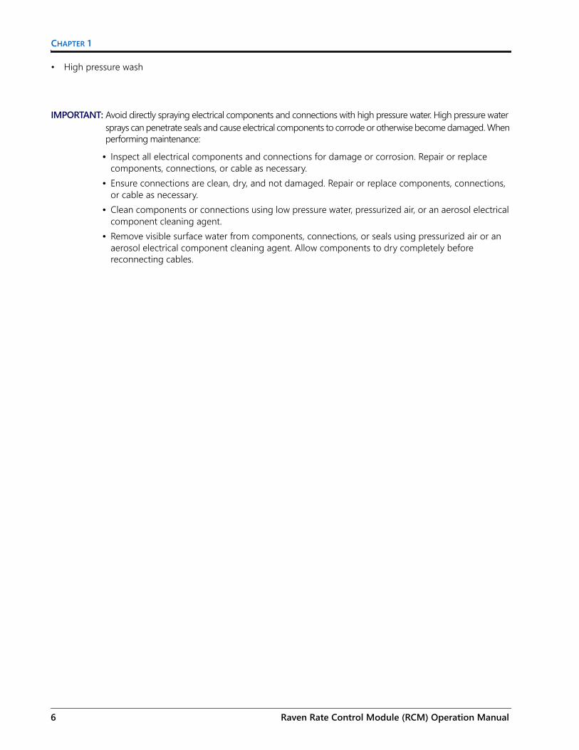
IMPORTANT: Avoid directly spraying electrical components and connections with high pressure water. High pressure water sprays can penetrate seals and cause electrical components to corrode or otherwise become damaged. When performing maintenance:
• Inspect all electrical components and connections for damage or corrosion. Repair or replace components, connections, or cable as necessary.
• Ensure connections are clean, dry, and not damaged. Repair or replace components, connections, or cable as necessary.
• Clean components or connections using low pressure water, pressurized air, or an aerosol electrical component cleaning agent.
• Remove visible surface water from components, connections, or seals using pressurized air or an aerosol electrical component cleaning agent. allow components to dry completely before reconnecting cables.
4 Raven Rate Control Module (RCM) Operation Manual

IMPORTANT SAFETY INFORMATION
INSTRUCTIONS FOR HOSE ROUTINGThe word “hose” is used to mean all flexible fluid carrying components. Follow existing hoses as much as possible and use these guidelines:
Hoses should not contact or be attached to:• Components with high vibration forces• Components carrying hot fluids beyond component specifications
Avoid contact with any sharp edge or abrading surfaces such as, but not limited to:• Sheared or flame cut edges• Edges of machined surfaces• Fastener threads or cap screw heads• Ends of adjustable hose clamps
Routing should not allow hoses to:• Hang below the unit• Have the potential to become damaged due to exposure to the exterior environment. (i.e. tree limbs, debris,
attachments)• Be placed in areas of or in contact with machine components which develop temperatures higher than the
temperature rating of hose components• Hoses should be protected or shielded if it needs to route near hot temperatures beyond hose component
specifications
Hoses should not have sharp bends
Allow sufficient clearance from machine component operational zones such as:• Drive shafts, universal joints and hitches (i.e. 3-point hitch)• Pulleys, gears, sprockets• Deflection and backlash of belts and chains• Adjustment zones of adjustable brackets• Changes of position in steering and suspension systems• Moving linkages, cylinders, articulation joints, attachments• Ground engaging components
For hose sections that move during machine operation:• Allow sufficient length for free movement without interference to prevent: pulling, pinching, catching or
rubbing, especially in articulation and pivot points• Clamp hoses securely to force controlled movement to occur in the desired hose section• Avoid sharp twisting or flexing of hoses in short distances
Protect hoses from:• Foreign objects such as rocks that may fall or be thrown by the unit• Buildup of dirt, mud, snow, ice, submersion in water and oil• Tree limbs, brush and debris• Damage where service personnel or operators might step or use as a grab bar• Damage when passing through metal structures
016-0171-637 Rev. E 5
CHAPTER 1
• High pressure wash
IMPORTANT: Avoid directly spraying electrical components and connections with high pressure water. High pressure water sprays can penetrate seals and cause electrical components to corrode or otherwise become damaged. When performing maintenance:
• Inspect all electrical components and connections for damage or corrosion. Repair or replace components, connections, or cable as necessary.
• Ensure connections are clean, dry, and not damaged. Repair or replace components, connections, or cable as necessary.
• Clean components or connections using low pressure water, pressurized air, or an aerosol electrical component cleaning agent.
• Remove visible surface water from components, connections, or seals using pressurized air or an aerosol electrical component cleaning agent. Allow components to dry completely before reconnecting cables.
6 Raven Rate Control Module (RCM) Operation Manual

CHAPTER2
016-0171-637 Rev. E
CHAPTER 2INTRODUCTION
The Raven Rate Control Module (RCM) is a multi-product application control system built on an ISOBUS platform. The Raven Rate Controller Module is designed to provide a machine operator the ability to simultaneously monitor and control five product applications such as liquid, granular, NH3, and direct injection via ISOBUS Universal Terminal (UT) and task control for as-applied documentation, prescription rate, and section control.
This document is intended to provide information regarding the following aspects of the Raven Rate Control Module:• Initial Setup and Navigation• Calibration• Raven Rate Control Module System Operation• Raven Rate Control Module Alarms• Updating Raven Rate Control Module Components
NOTE: Prior to using the Raven Rate Control Module control features with any UT display, the Raven Rate Control Module electronic control unit (ECU) must be calibrated for the control system. Refer to Chapter 3, ISOBUS System Calibration, for assistance with completing the initial calibration wizard.
This manual assumes that the required control hardware is already installed on supported equipment and is properly connected. Contact a local Raven dealer for additional information on supported equipment configurations.
RAVEN RATE CONTROL MODULE™ FEATURES
DIRECT INJECTIONThe Raven Sidekick™ Pro ICD provides for an optimal user experience by allowing control of direct injection through the Raven Rate Control Module interface. By using a separate injection module or tank, the system eliminates mixing chemicals in the tank, reduces chemical waste, and simplifies equipment care and maintenance. Connect up to four injection systems to the Viper 4 and ISOBUS to control the whole system through the Raven Rate Control Module user interface screens on the virtual terminal. Purchase a high flow injection system to control a wide range of chemical flow rates from 5 - 200 oz/min. Purchase a low flow injection system to provide chemical flow rates from 1 - 40 oz/min. Refer to the Sidekick™ ICD Manual for additional information on high and low flow injection systems.
Contact a local Raven dealer for additional details on direct injection using Sidekick Pro™ with Raven Rate Control.
7

CHAPTER 2
MACHINE TYPESThe Raven Rate Control Module can be used with:
TABLE 1. RCM Machine List
Machine Type Application Mode Application Type
Self-Propelled SprayerPull-Behind Sprayer
LiquidLiquid Tiered (Direct)Liquid Tiered (External)Liquid Constant Flow
Liquid
Liquid Fertilizer Tool
LiquidLiquid Tiered (Direct)Liquid Tiered (External)Liquid Constant FlowLiquid Slurry DraglineLiquid Slurry
Liquid
NH3 Tool NH3NH3 HP+ NH3
Self-Propelled SpreaderPull-Behind Spreader
Dry Manure/LitterGranular Full WidthGranular RPM CompensatedGranular RPM MaintainedGranular Split BeltGranular Dual Control Valve
Granular FertilizerGranular Seed
Air CartGeneric
LiquidGranular Full WidthGranular RPM CompensatedGranular RPM MaintainedGranular Split BeltGranular Dual Control ValveGranular Meter Per Section
LiquidGranular
PlanterPlanter Section ControlSeed Rate Control (/W Clutches)See Rate Control (no Clutches)
NA
Scale NA NA
8 Raven Rate Control Module (RCM) Operation Manual

INTRODUCTION
CARE AND USEAlways follow equipment manufacturer’s recommended maintenance procedures for storing equipment. The following maintenance procedures are generally recommended for storing equipment with the Raven Rate Control Module:1. Empty product from the chemical supply tank and flush the application system with water.2. Remove hardened chemical residues or build up by flushing the system with:
a. kerosene or fuel oil if the last product applied was petroleum based.b. soap and water if the last product applied was water based.
3. Prime the system plumbing with a 50% water and automotive antifreeze mixture to prevent freezing of components. Freezing will result in damage to the system and other plumbing components on the system.
NOTE: Refer to Appendix D, Maintenance Schedule and Replacement Parts, for additional assistance with maintaining the Raven Rate Control Module.
FEATURE UNLOCKSEvery RCM comes with different levels of unlocks. To purchase additional unlocks, navigate to portal.ravenprecision.com and purchase the desired unlocks. The table below lists unlock levels:
TABLE 2. RCM Unlocks
Level ECU P/N Features
0 063-0173-940• Ground drive/no control valve product monitoring/no task
controller interface (section control, as applied documentation)• Generic single channel scale/no application control
1 063-0173-941
• Single product control with section shut-off• Liquid NH3(HP+)/Granular• Dual valve control (no support for multiple rate control sections)• Spinner/fan control (two channel)• No scale support (product or general purpose) with products
enabled.• Multiple Sidekick ICD control supported• Task controller support for ground drive transmission (section
control, as-applied documentation)• Planter section control - up to 16 sections/clutches• Generic four channel scale/no application control
2 063-0173-756
• Multi-product application control (up to five products)• Scale support in conjunction with application control• Tiered boom (two tiers)• Multiple rate control sections (with or without VRA capability)• Planter section control - up to 32 sections/clutches
3 063-0173-953
• Granular Meter per Section• Planter Seed Rate Control (with clutches)• Planter Seed Rate Control (without clutches)• Manure/Litter spreader
016-0171-637 Rev. E 9

CHAPTER 2
UPDATESUpdates for Raven manuals as well as software updates for Raven consoles, and product controllers are available at the Applied Technology Division web site:
https://portal.ravenprecision.com
The Raven Service Tool and a laptop PC are required to perform software updates of the Raven Rate Control Module. Refer to the Raven Service Tool Operation manual for additional assistance with updating the Raven Rate Control Module.
Sign up for e-mail alerts to receive notifications when updates for your Raven products are available on the Raven web site.
3 Stack Tiered Boom 077-0180-202 • Enable for three stacks or tiers (A, B, and C or a combination
thereof).3 Stack Blockage Monitoring
077-0180-201• Enable interfacing to a third party blockage monitoring system to
provide section awareness from RCM.
At Raven Industries, we strive to make your experience with our products as rewarding aspossible. One way to improve this experience is to provide us with feedback on this manual.Your feedback will help shape the future of our product documentation and the overall service weprovide. We appreciate the opportunity to see ourselves as our customers see us and are eagerto gather ideas on how we have been helping or how we can do better.To serve you best, please send an email with the following information to
-Raven Rate Control Module (RCM) Operation Manual-016-0171-637 Rev. E-Any comments or feedback (include chapter or page numbers if applicable).-Let us know how long have you been using this or other Raven products.We will not share your email or any information you provide with anyone else. Your feedback isvalued and extremely important to us.Thank you for your time.
TABLE 2. RCM Unlocks
Level ECU P/N Features
10 Raven Rate Control Module (RCM) Operation Manual

CHAPTER3
016-0171-637 Rev. E
CHAPTER 3LIQUID OPERATION
LIQUID MACHINE LIST
LIQUID FERTILIZER CONFIGURATIONThis section provides a liquid fertilizer configuration example. Depending on machine configuration the following screens will vary.1. Select the desired sprayer type from the Machine Type drop down.
TABLE 1. RCM Liquid Machine List
Machine Type
Application Type Application Mode Application Mode Uses
• Self-Propelled Sprayer
• Pull-Behind Sprayer
• Liquid
LiquidConventional Liquid application. Application rate is entered and documented as gallons/acre (liters/hectare).
Liquid Tiered (Direct)Tiered boom liquid application in which two-way boom valves are controlled directly by signals provided by the rate controller.
Liquid Tiered (External)
Tiered boom liquid application in which two-way boom valves are controlled by an external module using section and tier signals by the rate controller.
Liquid Constant FlowSingle boom liquid application using three-way boom valves that divert flow back to tank in the off position.
Tiered Boom - Low Side Drive
The controller will activate tiers by supplying a ground (earth) signal that can be connected to the return (low side) of the valve bank. The signal will float when the tier is off, causing the connected valve bank to turn off.
• Liquid Fertilizer Tool
• LiquidLiquid Slurry Dragline
Liquid application for products that do not have a control valve and require a large application rate like liquid manure.
Liquid SlurryConventional liquid application for products that require a large application rate like liquid manure.
11
CHAPTER 3
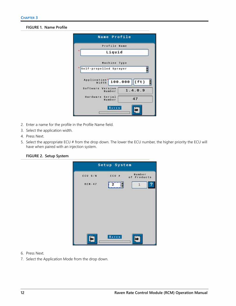
FIGURE 1. Name Profile
2. Enter a name for the profile in the Profile Name field.3. Select the application width.4. Press Next.5. Select the appropriate ECU # from the drop down. The lower the ECU number, the higher priority the ECU will
have when paired with an injection system.
FIGURE 2. Setup System
6. Press Next.7. Select the Application Mode from the drop down.
12 Raven Rate Control Module (RCM) Operation Manual

LIQUID OPERATION
FIGURE 3. Setup Application Type
8. Press Next.9. On the Setup Sections screen, enter the Number of Sections and select the Section Valve Type.
FIGURE 4. Setup Sections
10. If desired, select the Equal Width Sections and Fence Rows Enable check boxes.11. Press Next.12. Select the fence row driver for each fence row (if selected earlier).
016-0171-637 Rev. E 13

CHAPTER 3
FIGURE 5. Setup Fence Row Drivers
13. Press Next.14. Review the section width information on the Setup Section Width screen.
FIGURE 6. Setup Section Width
15. If needed, adjust the section widths.16. Press Next.17. If desired, configure auxiliary drivers on the Setup Auxiliary Drivers screen. Auxiliary drivers are additional
switches that provide a 12V signal to a device.
14 Raven Rate Control Module (RCM) Operation Manual

LIQUID OPERATION
FIGURE 7. Setup Auxiliary Drivers
18. Press Next.19. Review the information on the Section Summary screen.
FIGURE 8. Section Summary
20.Press Next.21. Select the appropriate pressure sensors configuration for each pressure sensor.
016-0171-637 Rev. E 15

CHAPTER 3
FIGURE 9. Setup Pressure Sensors
22.Press Next.23. If desired, set the Min and Max pressures and select the Alarm? check box for each pressure sensor.
FIGURE 10. Setup Pressure Alarms
24.Press Next.25. If an agitator is installed and will be used, select the Agitator Installed checkbox and configure the Agitator
Duty Cycle. Also select the Flow Return Installed checkbox if desired.
16 Raven Rate Control Module (RCM) Operation Manual

LIQUID OPERATION
FIGURE 11. Setup Auxiliary Functions
26.Press Next.27.On the Setup Control Valve page, configure the information for the product. This includes selecting the Control
Valve Type, Valve Response Rate, and Control Deadband.
FIGURE 12. Setup Control Valve
28.Press Next.29.Configure the rate sensor for the product by entering the Flowmeter Calibration and selecting the Flowmeter
Pulses/Units.
016-0171-637 Rev. E 17

CHAPTER 3
FIGURE 13. Setup Rate Sensors
30.Press Next. 31. Select the Tank Fill/Level Sensor and enter the Tank Capacity, Current Tank Level, and Low Tank Level for the
product.
FIGURE 14. Setup Tank/Bin
32. If desired, select the Alarm? checkbox for the Low Tank Level.33.Press Next.34.Enter the Preset Rate Values and Rate Bump values for the product.
18 Raven Rate Control Module (RCM) Operation Manual

LIQUID OPERATION
FIGURE 15. Setup Rates
35.Select the desired Rate Selection from the drop down.36. If desired, select the Display Smoothing check box and select the Decimal Shift number.37.Enter a Standby Pressure. 38.Press Next.39. If desired, enter a Off Rate Alarm percentage and select the Alarm? check box.
FIGURE 16. Setup Alarms
40.Review the information on the Setup Summary page. If the configuration is not correct, press back and make the necessary adjustments. If the configuration is correct, press Next.
016-0171-637 Rev. E 19
CHAPTER 3
LIQUID RUN PAGE OVERVIEWThe image below is an example of a typical run screen.
FIGURE 17. Liquid Run Screen
PRODUCT TABSPress on the product tab to select the desired product. This will open the product run screen for that product.
CURRENT PRODUCT RUN SCREENThe current product run screen displays information for the selected product. Each product run screen will vary based on product configuration.
Data Fields display selected settings and can be changed to the operator’s preferences.
FIGURE 18. Liquid Run Screen
Product Tabs
Current Product Run Screen
Main
Setup
Totals
Diagnostics
1 3
4
2
8
10
1112
6
7
1415
9
16513
17
20 Raven Rate Control Module (RCM) Operation Manual

LIQUID OPERATION
TABLE 2. Liquid Run Screen Information
Button Description Function/Operation
1 Actual Rate Displays the actual application rate.
2 Preset Rate BumpProvides the user the to increase the rate by the preconfigured rates defined during configuration.
3 Target Rate
Displays the current target rate. The target rate can be adjusted by pressing in the number cell and entering a new number.
4 Rate Bump/Presets
This will either display Rate Bump or Presents. This increases the rate by the rate bump value defined during configuration.
5 Flow Rate Displays the gal/min going through the flow meter.
6 Traveling Speed Shows the implement/machine speed.
7 Tank Level Displays the current tank level.
8 Section Switch Box Button
Indicates if the switch box is on or off:• Green - On• Red - OffPress the switch box button to navigate to a screen that allows the user to turn off the switch boxes for individual sections.
9 Master Switch Indicator
The Master Switch Indicator shows the status of the master switch.• Green - On• Red - Off• Orange - Cycle the master
switch
10 Section Status
Displays the spray status of each section.• Green - On• Gray - Off
016-0171-637 Rev. E 21

CHAPTER 3
MAINPress main at any time to return to the Current Product Run Screen.
SETUPPressing setup opens a screen with many tabs.
FIGURE 19. Setup Tabs
11 Fence Row Provides the user the ability to turn the fence rows on or off.
12 Application Volume Displays the tally register volume applied.
13 Applied Acres Displays the number of acres applied.
14 Manual/Automatic TogglePress this to switch between manual and automatic operation.
15 Product Tab Select a tab to view information for that product.
16 Low Pressure Low pressure reading.
17 Quick StartSelect this to quickly configure/start a liquid application.
Button Description Function/Operation
Applicator Setup
System Setting
Alarms Rates Feature Unlocks
22 Raven Rate Control Module (RCM) Operation Manual

LIQUID OPERATION
APPLICATOR SETUP TABThe Applicator Setup Tab provides options to create a new, edit, or remove an applicator. This tab also provides a summary to the section configuration. For more information on the Precision Farming Setup button, refer to Chapter 9, Precision Farming.
SYSTEM SETTINGSThe system settings provides many buttons that allow the user to modify the current configuration. The table below describes each button in detail.
ALARM SETTINGSPress the Alarm Settings tab to modify or update alarm settings such as Off Rate Alarm and the Minimum Flow Rate. There is also an option to update the Pressure Alarm.
RATES SETUPThe Rates Setup tab allows the user to adjust the Preset Rate Values, Rate Bump, Rate Selection, and other values that were entered during the original configuration.
TABLE 3. System Settings
Button Description
Control Valve Setup
The Control Valve button allows the user to adjust the following settings for each product:• Valve Response Rate• Control Deadband• Valve Delay• Valve Advance• Control Effort
Rate Sensor Setup
The Rate Sensor Setup button provides the options to adjust the following settings:• Flowmeter Calibration• Flowmeter Pulse/Units• Flowmeter Low Limit• Tank Fill Flowmeter Calibration• Tank Fill Flowmeter Pulse/UnitsThere is also the option to perform a catch test and applied product calibration.
Tank Fill Settings This button allows the user to enter the Tank Capacity, Current Tank Level, and Low Tank Level.
Display Setup Menu The Display Setup Menu allow the user to configure the main run screen.
Pressure Sensor Setup This button allows the user to modify the alarm Min and Max for any products that have pressure alarms selected.
Auxiliary Functions The Auxiliary Functions button allows the user to create new or modify existing auxiliary functions such as RPM sensors.
Scale Setup Scale Setup allows the user to configure scale options.
016-0171-637 Rev. E 23

CHAPTER 3
FEATURE UNLOCKSIf there are additional features available for the RCM, enter the provided Activation Key to access these features.
TOTALSThe totals button provides options to access a Current Totals, Device totals, and Distance totals tabs.
DIAGNOSTICSSelecting the Diagnostics button open a window with tabs for the items listed below.
SYSTEM INFORMATIONDisplays information about the RCM including the Hardware Serial Number, Hardware Revision, and Software Version Number.
TESTSThe Tests tab allows the user to select various tests from a dropdown. These list of tests will vary by product configuration.
DIAGNOSTIC TROUBLE CODESThis tab lists Active and Inactive diagnostic trouble codes as well as the ability to Clear the active codes.
SYSTEM SUMMARYDisplays information configured during the setup process but does not provide the option to modify the configuration.
PRODUCT SUMMARYThe Product Summary provides a brief summary for all of the products such as Application Type, Control Valve type, Target Rate, and other settings. This tab does not allow the user to modify the configurations.
AUXILIARY DRIVERSAuxiliary drivers that were created during configuration are listed in Auxiliary Drivers.
24 Raven Rate Control Module (RCM) Operation Manual

LIQUID OPERATION
FIGURE 20. Auxiliary Drivers
To give the driver a custom name, press in the Driver Name field and, using the keypad, enter the desired name.
To activate the auxiliary driver, select the driver number button next to the desired driver.
Driver Number Button
DriverNameField
016-0171-637 Rev. E 25

CHAPTER 3
26 Raven Rate Control Module (RCM) Operation Manual

CHAPTER4
016-0171-637 Rev. E
CHAPTER 4ANHYDROUS AMMONIA (NH3) OPERATION
NH3 MACHINE LISTTABLE 1. RCM NH3 Machine List
NH3 CONFIGURATION1. Select the desired Machine Type from the drop down.
FIGURE 1. Name Profile
2. Enter the desired Profile Name.3. Enter the Application Width.4. Press Next.5. Select the appropriate ECU # from the drop down. The lower the ECU number, the higher priority the ECU will
have when paired with an injection system.
Machine Type
Application Type Application Mode Application Mode Uses
• NH3 Toolbar • NA NH3 NH3 applicator or single valve configuration.NH3 HP+ NH3 applicator or single valve configuration.
27

CHAPTER 4
FIGURE 2. Setup System
6. Enter the desired Number of Products.7. Press Next.8. Select the desired Application Mode for each product.
FIGURE 3. Setup Application Type
9. Press Next.10. Enter the Number of Sections and, if desired, select the Equal Width Sections check box.
28 Raven Rate Control Module (RCM) Operation Manual

ANHYDROUS AMMONIA (NH3) OPERATION
FIGURE 4. Setup Sections
11. Press Next.12. Verify the section widths are correct.
FIGURE 5. Setup Section Width
13. Press Next.14. If desired, select an Auxiliary Driver. Auxiliary drivers are additional switches that provide a 12V signal to a
device.
016-0171-637 Rev. E 29

CHAPTER 4
FIGURE 6. Setup Auxiliary Drivers
NOTE: Unused section drivers are necessary to set up auxiliary drivers and to run independently of any product control.
15. Press Next.16. Select the Latched Output to allow the driver to stay on until a the driver button is pressed again.
FIGURE 7. Setup Auxiliary Drivers
17. Review the information on the Section Summary screen.
30 Raven Rate Control Module (RCM) Operation Manual

ANHYDROUS AMMONIA (NH3) OPERATION
FIGURE 8. Section Summary
18. If the information is correct, press Next. To make adjustments to the configuration, press Back and adjust settings as needed.
19. Select the Product Scale type and the corresponding scale(s).
NOTE: General purpose scales are not associated with a product control channel.20.Select the desired scale.
FIGURE 9. Scale Setup
21. Press Next.22.Enter the Min and Max value for the pressure alarms.
016-0171-637 Rev. E 31

CHAPTER 4
FIGURE 10. Setup Pressure Alarms
23.Press Next.24.Press Next.25.Enter the Min and Max values for the pressure alarms.26.Select the Control Valve Type.
FIGURE 11. Setup Control Valve
27.Enter the desired Valve Response Rate, Control Deadband, and Control Effort.28.Press Next.29.Enter the Flowmeter Calibration.
32 Raven Rate Control Module (RCM) Operation Manual

ANHYDROUS AMMONIA (NH3) OPERATION
FIGURE 12. Setup Rate Sensor
30.Press Next.31. Enter the Tank Capacity, Current Tank Level, and Low Tank Level values.
FIGURE 13. Setup Tank/Bin
32. If desired, select the Alarm? checkbox for the Low Tank Level.33.Press Next.34.Enter the Preset Rate Values and the Rate Bump value.
016-0171-637 Rev. E 33

CHAPTER 4
FIGURE 14. Setup Rates
35.Select the Rate Selection and, if desired, select Display Smoothing.36.Enter a Standby Pressure. This is the pressure the rate controller will attempt to maintain when all of the
sections are off. 37.Press Next.38. If desired, enter values for the Off Rate Alarm and select the Alarm? checkbox(es) for Off Rate Alarm and the
Section Valve Status Feedback Alarm.
FIGURE 15. Setup Alarms
39.Press Next.40.Review the information on the Setup Summary page.
34 Raven Rate Control Module (RCM) Operation Manual

ANHYDROUS AMMONIA (NH3) OPERATION
FIGURE 16. Setup Summary
41. If desired, press Back to adjust the configuration settings. If the configuration is correct, press Next.
016-0171-637 Rev. E 35

CHAPTER 4
NH3 RUN PAGE OVERVIEWThe image below is an example of a typical run screen.
FIGURE 17. NH3 Run Screen
PRODUCT TABSPress on the product tab to select the desired product. This will open the to product run screen for that product.
CURRENT PRODUCT RUN SCREENThe current product run screen displays information for the selected product. Each product run screen will vary based on product configuration.
Data Fields display selected settings and can be changed to the operator’s preferences.
RUN PAGE OVERVIEWData Fields display selected settings and can be changed to the operator’s preferences.
Auxiliary Drivers
Product Tabs
Current Product Run Screen
Main
Setup
Totals
Diagnostics
1
23 4
67
8
10
1112
14
15
16
9
13
5
36 Raven Rate Control Module (RCM) Operation Manual

ANHYDROUS AMMONIA (NH3) OPERATION
TABLE 2. Raven RCM Run Time Widgets
Button Description Function/Operation
1 Product Tabs Select a tab to view information for that product.
2 Applied Area Displays the number of acres applied.
3 Application Volume Displays the tally register volume applied.
4 Traveling Speed Displays the current machine traveling speed.
5 Section Switch Box buttonIndicates if the switch box is on or off:• Green - On• Red - Off
6 Actual Rate Displays the actual application rate.
7 Target Rate Displays the target application rate.
8 Manual/Automatic Toggle Press this to switch between manual and automatic operation.
9 Product On/Off Toggle Press this to manually turn a product on or off.
11 Preset Rate ButtonProvides the user the to increase the rate by the preconfigured rates defined during configuration.
12 Application Rate Displays the current application rate in pounds per minute.
13 Duty Cycle Displays the current duty cycle.
14 Master Switch Indicator
The Master Switch Indicator shows the status of the master switch.• Green - On• Red - Off• Orange - Cycle the master switch
15 Implement Sections Displays if the display section is on or off.
16 Tank Level Indicator and Fill Button Displays the current tank fill level.
016-0171-637 Rev. E 37

CHAPTER 4
MAINPress main at any time to return to the Current Product Run Screen.
SETUPPressing setup opens a screen with many tabs.
FIGURE 18. Setup Tabs
APPLICATOR SETUP TABThe Applicator Setup Tab provides options to create a new, edit, or remove an applicator. This tab also provides a summary to the section configuration. For more information on the Precision Farming Setup button, refer to Chapter 9, Precision Farming.
SYSTEM SETTINGSThe system settings provides many buttons that allow the user to modify the current configuration. The table below describes each button in detail.
Applicator Setup
System Setting
Alarms Rates Feature Unlocks
38 Raven Rate Control Module (RCM) Operation Manual

ANHYDROUS AMMONIA (NH3) OPERATION
TABLE 3. System Settings
ALARM SETTINGSPress the Alarm Settings tab to modify or update alarm settings such as Off Rate Alarm and the Minimum Flow Rate. There is also an option to update the Pressure Alarm.
RATES SETUPThe Rates Setup tab allows the user to adjust the Preset Rate Values, Rate Bump, Rate Selection, and other values that were entered during the original configuration.
FEATURE UNLOCKSIf there a additional features available for the RCM, enter the provided Activation Key to access these features.
TOTALSThe totals button provides options to access a Current Totals, Device totals, and Distance totals tabs.
DIAGNOSTICSSelecting the Diagnostics button open a window with tabs for the items listed below.
Button Description
Control Valve Setup
The Control Valve button allows the user to adjust the following settings for each product:• Valve Response Rate• Control Deadband• Valve Delay• Valve Advance• Control Effort
Rate Sensor Setup
The Rate Sensor Setup button provides the options to adjust the following settings: • Flowmeter Calibration• Flowmeter Pulse/Units• Flowmeter Low Limit• Tank Fill Flowmeter Calibration• Tank Fill Flowmeter Pulse/UnitsThere is also the option to perform a catch test and applied product calibration.
Tank Fill Settings This button allows the user to enter the Tank Capacity, Current Tank Level, and Low Tank Level.
Display Setup Menu The Display Setup Menu allows the operator to configure the main run screen.
Pressure Sensor Setup This button allows the user to modify the alarm Min and Max for any products that have pressure alarms selected.
Auxiliary Functions The Auxiliary Functions button allows the user to create new or modify existing auxiliary functions.
Scale Setup Scale Setup allows the user to configure scale options.
016-0171-637 Rev. E 39

CHAPTER 4
SYSTEM INFORMATIONDisplays information about the RCM including the Hardware Serial Number, Hardware Revision, and Software Version Number.
TESTSThe Tests tab allows the user to select various tests from a dropdown. These list of tests will vary by product configuration.
DIAGNOSTIC TROUBLE CODESThis tab lists Active and Inactive diagnostic trouble codes as well as the ability to Clear the active codes.
SYSTEM SUMMARYDisplays information configured during the setup process but does not provide the option to modify the configuration.
PRODUCT SUMMARYThe Product Summary provides a brief summary for all of the products such as Application Type, Control Valve type, Target Rate, and other settings. This tab does not allow the user to modify the configurations.
AUXILIARY DRIVERSAuxiliary drivers that were created during configuration are listed in Auxiliary Drivers.
FIGURE 19. Auxiliary Drivers
To give the driver a custom name, press in the Driver Name field and, using the keypad, enter the desired name.
To activate the auxiliary driver, select the driver number button next to the desired driver.
Driver Number Button
DriverName
Field
40 Raven Rate Control Module (RCM) Operation Manual

CHAPTER5
016-0171-637 Rev. E
CHAPTER 5SPREADER OPERATION
SPREADER MACHINE LISTTABLE 1. RCM Spreader Machine List
Machine Type
Application Type Application Mode Application Mode Uses
• Self-Propelled Spreader
• Pull-Behind Spreader
• Granular Fertilizer
• Granular Seed
Dry Manure/LitterGranular full width using product scales to adjust product density on the go during in-field operations.
Granular Full WidthDry or seed application using a single shutoff section.Application rate is entered and documented as lbs/acre [kg/ha].
Granular RPM Compensated
Dry or seed application using multiple shutoff sections.Meter/conveyor RPM is controlled/compensated based upon machine speed and active width as sections turn on and off. Application rate is entered and documented as lbs/acre [kg/ha].
Granular RPM Maintained
Granular multi-section RPM maintained dry or seed application using multiple shutoff sections.Meter/conveyor RPM is controlled/compensated based upon machine speed. Meter/conveyor RPM is not compensated for changes in active width as sections turn on and off. Meter/conveyor will be stopped when all sections are off. Application rate is entered and documented as lbs/acre [kg/ha].
41

CHAPTER 5
Spreader configuration on the RCM can also support the following legacy applications:
(Cont.)• Self-Propelled Spreader
• Pull-Behind Spreader
(Cont.)• Granular Fertilizer
• Granular Seed
Granular Split Belt
Dry or seed application using one control valve of a split meter/conveyor RPM is available for each section.Meter/Conveyor RPM is not compensated for changes in active width as left or right sections turn on and off. Meter/conveyor will be stopped when both sections are off.
Granular Dual Control Valve
Dual Control Valve Dry or seed application using dual PWM control valves to independently control a left and right meter/conveyor section.Encoder feedback of meter or conveyor RPM is available for each section. Meter/conveyor RPM is independently controlled/compensated based on machine speed. Sections are turned off by closing the PWM control valve.
TABLE 2. Legacy Granular Modes
Legacy Granular Application Mode
New Application Mode Mode Details
Gran 1 Granular Full Width Selection
Dry or seed application using a single shutoff section.Application rate is entered and documented as Pounds/Acre (Kilograms/Hectare).
Gran 2Granular Section Control RPM Maintained
Dry or seed application using multiple shutoff sections.Meter/conveyor RPM is controlled/compensated based upon machine speed and active width as sections turn on and off. Application rate is entered and documented as lbs/acre [kg/ha].
Gran 3 Granular Split Tank/Dual Encoder
Dry or seed application using one control valve for a split meter/conveyor with shutoff control of two independent sections.Encoder feedback of meter or conveyor RPM is available for each section. Meter/conveyor RPM is controlled/compensated based upon the vehicle speed.Meter/conveyor RPM is not compensated for changes in active section width as left or right sections turn on and off. Meter/conveyor will be stopped when both sections are off.
Gran 4Granular Section Control RPM Maintained
The Granular Section Control RPM Maintained is listed above for Gran 2. If this is the correct mode for the Legacy Gran 4, we should be able to copy the mode details from above.
TABLE 1. RCM Spreader Machine List
Machine Type
Application Type Application Mode Application Mode Uses
42 Raven Rate Control Module (RCM) Operation Manual

SPREADER OPERATION
Gran 5Granular Section Control RPM Compensated
Dry or seed application using multiple shutoff sections.Meter/conveyor RPM is controlled/compensated based upon vehicle speed. Meter/conveyor RPM is not compensated for changes in active width as sections turn on and off. Meter/conveyor will be stopped when all sections are off. Application rate is entered and documented as lbs/acre [kg/ha].
None Dual Control Valve
Dry or seed application using dual PWM control valves to independently control a left and right meter/conveyor section.Encoder feedback of meter or conveyor RPM is available for each section. Meter/conveyor RPM is independently controlled/compensated based upon vehicle speed. Sections are turned off by closing the PWM control valve.
None Granular Meter Per Section
Dry or seed application using PWM control valves to independently control a meter/conveyor section.Up to 16 individual control sections can be configured. Encoder feedback of meter or conveyor RPM is available for each section. Meter/conveyor RPM is independently controlled/compensated based upon vehicle speed. Sections are turned off by closing the PWM control valve.
NOTE: This mode is only available when the Generic machine type selected or in Air Cart mode.
TABLE 2. Legacy Granular Modes
Legacy Granular Application Mode
New Application Mode Mode Details
016-0171-637 Rev. E 43
CHAPTER 5
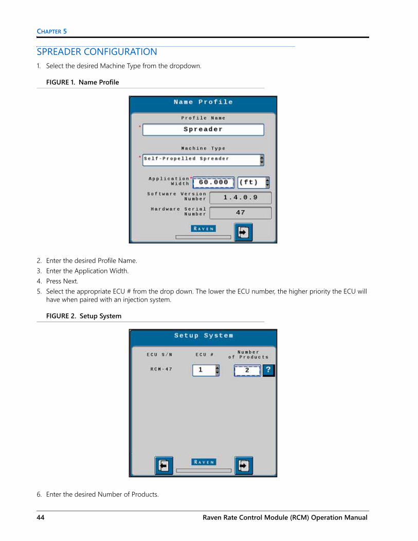
SPREADER CONFIGURATION1. Select the desired Machine Type from the dropdown.
FIGURE 1. Name Profile
2. Enter the desired Profile Name.3. Enter the Application Width.4. Press Next.5. Select the appropriate ECU # from the drop down. The lower the ECU number, the higher priority the ECU will
have when paired with an injection system.
FIGURE 2. Setup System
6. Enter the desired Number of Products.
44 Raven Rate Control Module (RCM) Operation Manual

SPREADER OPERATION
7. Press Next.8. Select the desired number of spinner/fans.
FIGURE 3. Setup Fan/Spinner RPM
9. If desired, select the Enable Fan/Spinner RPM Control checkbox.10. Press Next.11. Select the Application Type for each Product.
FIGURE 4. Setup Application Type
12. Press Next.13. Select the Application Mode for each product.
016-0171-637 Rev. E 45

CHAPTER 5
FIGURE 5. Setup Application Type Screen Two
14. Press Next.15. Review the information on the Setup Section Groups screen.
FIGURE 6. Setup Section Groups
16. Press Next.17. Enter the Number of Sections.
46 Raven Rate Control Module (RCM) Operation Manual

SPREADER OPERATION
FIGURE 7. Setup Selections
18. If desired, select the Equal Width Sections and/or Granular Product Sections Power to Apply check boxes.19. Press Next.20.Verify the section widths are correct.
FIGURE 8. Setup Section Width
21. Press Next.22. If desired, select an Auxiliary Driver. Auxiliary drivers are additional switches that provide a 12V signal to a
device.
016-0171-637 Rev. E 47

CHAPTER 5
FIGURE 9. Setup Auxiliary Drivers
NOTE: Unused section drivers are necessary to set up auxiliary drivers and to run independently of any product control.
23.Press Next.24.Select the Latched Output to allow the driver to stay on until a the driver button is pressed again.
FIGURE 10. Setup Auxiliary Drivers
25.Review the information on the Section Summary screen.
48 Raven Rate Control Module (RCM) Operation Manual

SPREADER OPERATION
FIGURE 11. Section Summary
26. If the information is correct, press Next. To make adjustments to the configuration, press Back and adjust settings as needed.
27.Select the Product Scale type and the corresponding scale(s).
FIGURE 12. Scale Setup
28.Press Next.29.Enter the RPM Calibration, RPM 1 Low Limit, and RPM 1 High Limit information. If desired, select the Alarm?
checkbox(es).
016-0171-637 Rev. E 49

CHAPTER 5
FIGURE 13. Setup Fan/Spinner RPM Calibration
30.Press Next.31. Select the checkbox(es) for the products that will be assigned to RPM Sensor 1.
FIGURE 14. Setup RPM Sensor Assignment
32.Select the Control Valve Type for the product.
50 Raven Rate Control Module (RCM) Operation Manual

SPREADER OPERATION
FIGURE 15. Setup Control Valve
33.Enter the Valve Response Rate.34.Enter the Control Deadband.35. If desired, select Enable PWM Smart Control.36.Press Next.37.Enter the Coil Frequency, PWM High Limit, PWM Low Limit, and PWM Startup for the product.
FIGURE 16. Setup PWM
38.Press Next.39.Enter the Product Density, Spreader Constant, Pulses/Revolution, and Gate Height. The Gate Height must be
between one and three inches.
016-0171-637 Rev. E 51

CHAPTER 5
FIGURE 17. Setup Rate Sensor
40.Press Next.41. Enter the Tank Capacity and Low Tank Level.
FIGURE 18. Setup Tank/Bin
42.If desired, select the Alarm? and/or Low Bin Level Sensor checkbox(es).43.Select the Mid Bin Level Sensor Type.
NOTE: To test the sensor type, place an object in front of the sensor. If the voltage reads 12v it is a PNP sensor. If it reads ground, it is a NPN sensor.
44.Press Next.45.Enter the Preset Rate Values and the Rate Bump value.
52 Raven Rate Control Module (RCM) Operation Manual

SPREADER OPERATION
FIGURE 19. Setup Rates
46.Select the Rate Selection and Decimal Shift values.47. If desired, select Display Smoothing.48.Press Next.49.If desired, enter values for the Off Rate Alarm and Split Belt/Dual Encoder Alarm and select the Alarm?
checkbox(es).
FIGURE 20. Setup Alarms
50.Press Next.51. Repeat steps step 32 through step 49 for all products.52.Press Next.53.Review the information on the Setup Summary page.
016-0171-637 Rev. E 53

CHAPTER 5
FIGURE 21. Setup Summary
54.If desired, press Back to adjust the configuration settings. If the configuration is correct, press Next.
MANURE/LITTER CONFIGURATIONWhen paired with a scale system, the Raven Rate Control Module (RCM) can be used to compensate for varying product density within a spreader load. This capability offers optimal consistency of application even when the product composition is highly variable.
The dynamic calibration feature continually adjusts the “Density Factory” based upon user-entered settings for:• Adjustment Frequency - amount of product dispensed between adjustments• Adjustment Sensitivity - percent of adjustment that should be made based upon the sample
In addition, the clean out feature dynamically adjusts the spreader constant for the final port of a load based upon a user-entered trigger weight. This feature increases the PWM duty cycle to a maximum over time to better maintain an even distribution pattern as the load trails off while maintaining the calibration settings for applying a normal load.
A Level 3 RCM is required for these features and is only available for the Litter/Manure application mode configured for a granular spreader equipped with a product scale. Applicable part numbers include:
TABLE 3. Litter/Manure Part Numbers
Part Number Description063-0173-953 Raven Rate Control Module Level 3117-7100-007 Kit - RCM LVL 3 Gen 1 ISOBUS ECU Harness117-7100-008 Kit - RCM LVL 3 Gen 3 ECU Harness
54 Raven Rate Control Module (RCM) Operation Manual

SPREADER OPERATION
DYNAMIC CALIBRATIONTo access settings for Dynamic Calibration, navigate to the Rate Sensor Setup Page:
FIGURE 22. Setup Rate Sensor
1. On the Setup Rate Sensor screen, set the Density Factor to 70 lb/ft³ [1,121 kg/m³] as a starting point.
NOTE: The other settings on the Setup Rate Sensor screen are specific to the spreader equipment.2. Select the “Dynamic Cal Setup” button.3. Set the Adjustment Frequency and Adjustment Sensitivity settings to adjust the Density Factor to the correct
apron speed needed to apply at the desired rate.
FIGURE 23. Dynamic Cal Setup
DENSITY ADJUSTMENT FREQUENCYThe Adjustment Frequency value is used to determine how often the controller recalculates the Density Factor. Enter the weight in pounds [kilograms] dispensed before the controller makes an adjustment. The recommended starting point is 1/20th of the total load weight. This will result in 20 density adjustments per load. On very uneven loads, the Adjustment Frequency weight value can be decreased, however, rate fluctuation may be observed. If excessive rate fluctuation is occurring, increase the value.
016-0171-637 Rev. E 55

CHAPTER 5
ADJUSTMENT SENSITIVITYThe Adjustment Sensitivity percentage is used to set how aggressively the controller will adjust the Density Factor. It is recommended to leave this setting at the default setting of 50% unless otherwise instructed.
If the total applied weight displayed on the controller is not matching the actual scale weight applied, the Sensitivity percentage may be increased (not to exceed 75%). If erratic rates are observed, reduce this value (not to be set below 25%) but may lead to some variation between controller totals and scale totals.
CLEAN OUT SETUP1. On the Setup Rate Sensor screen, press the “Clean Out Setup” button to access the Clean Out settings.
FIGURE 24. Setup Rate Sensor
CLEAN OUT MODEThe Clean Out Mode is used to compensate for the end of a load when the beaters or spinners are no longer full. The apron chain will continue to speed up until it is at full speed. The controller will resume normal operation when the spreader has been refilled to above the trigger weight. Configuration of the clean out mode consists of two settings - Trigger Weight and Clean Out Duration.
FIGURE 25. Clean Out Setup
56 Raven Rate Control Module (RCM) Operation Manual

SPREADER OPERATION
TRIGGER WEIGHTWhen the scale reaches the weight set in the Trigger Weight field, the clean out mode will start. Set the Trigger Weight to the scale reading when the opening to the beaters or spinners is no longer completely covered.
CLEAN OUT DURATIONEnter the time in seconds during which the controller will gradually increase the apron chain speed. A value between 15 and 25 is a a recommended starting point for the Clean Out Duration setting.
The steeper the angle of the material left in the spreader when the Trigger Weight is reached, the shorter the Duration value should be.
LITTER/MANURE OPERATION TIPSFor greatest accuracy and optimal performance:• Use Quick Start feature to prime the Spreader. Toggle the master switch ON and press the Quick Start button in
the lower, right corner of the RCM run screen. The Quick Start feature will start the apron to run for up to 15 seconds while the equipment remains stopped. Toggle the master switch OFF to stop if necessary. Allow the apron to run until material starts to come out. Completing the Quick Start process will fill up the dead area between the gate and the beaters and help ensure that material is applied when the system is enabled for in-field application.
FIGURE 26. Quick Start Feature
• Full loads will have better accuracy than partial loads. The controller will still adjust for a partial load, but the changes in Density factor will be much greater.
• The Density Factor may be monitored by adding a widget to the main run screen. While the widget is not required to operate, it is helpful for monitoring the system. The Density Factor will increase as the beaters are more full or the material is heavier.
016-0171-637 Rev. E 57

CHAPTER 5
FIGURE 27. Product Density
SPREADER RUN PAGE OVERVIEWThe image below is an example of a typical run screen.
FIGURE 28. Spreader Run Screen
PRODUCT TABSPress on the product tab to select the desired product. This will open the to product run screen for that product.
CURRENT PRODUCT RUN SCREENThe current product run screen displays information for the selected product. Each product run screen will vary based on product configuration.
Data Fields display selected settings and can be changed to the operator’s preferences.
Auxiliary Drivers
Product Tabs
CurrentProduct Run
Screen
Main
Setup
Totals
Diagnostics
58 Raven Rate Control Module (RCM) Operation Manual

SPREADER OPERATION
RUN PAGE OVERVIEWData Fields display selected settings and can be changed to the operator’s preferences.
1
23 4
6
7
8
10
11
12
14
15
16
9
13
5
016-0171-637 Rev. E 59

CHAPTER 5
TABLE 4. Raven RCM Run Time Widgets
Button Description Function/Operation
1 Product Tabs Select a tab to view information for that product.
2 Applied Area Displays the number of acres applied.
3 Total Volume AppliedDisplays the total volume of product applied since the last time the tally was reset.
4 Traveling Speed Displays the current machine traveling speed.
5 Section Switchbox ButtonIndicates if the switchbox is on or off:• Green - On• Red - Off
6 Actual Rate Displays the actual application rate.
7 Target Rate Displays the target application rate.
8 Manual/Automatic Toggle Press this to switch between manual and automatic operation.
9 Product On/Off Toggle Press this to manually turn a product on or off.
11 Preset Rate ButtonProvides the user the to increase the rate by the preconfigured rates defined during configuration.
12 Application Rate Displays the current application rate in pounds per minute.
13 Duty Cycle Displays the current duty cycle.
14 Master Switch Indicator
The Master Switch Indicator shows the status of the master switch.• Green - On• Red - Off• Orange - Cycle the master switch
15 Implement Sections Displays if the display section is on or off.
16 Tank Level Indicator and Fill Button Displays the current tank fill level.
60 Raven Rate Control Module (RCM) Operation Manual

SPREADER OPERATION
MAINPress main at any time to return to the Current Product Run Screen.
SETUPPressing setup opens a screen with many tabs.
FIGURE 29. Setup Tabs
APPLICATOR SETUP TABThe Applicator Setup Tab provides options to create a new, edit, or remove an applicator. This tab also provides a summary to the section configuration. For more information on the Precision Farming Setup button, refer to Chapter 9, Precision Farming.
SYSTEM SETTINGSThe system settings provides many buttons that allow the user to modify the current configuration. The table below describes each button in detail.
Applicator Setup
System Setting Alarms Rates
Feature Unlocks
016-0171-637 Rev. E 61

CHAPTER 5
TABLE 5. System Settings
ALARM SETTINGSPress the Alarm Settings tab to modify or update alarm settings such as Off Rate Alarm and the Minimum Flow Rate. There is also an option to update the Pressure Alarm.
RATES SETUPThe Rates Setup tab allows the user to adjust the Preset Rate Values, Rate Bump, Rate Selection, and other values that were entered during the original configuration.
FEATURE UNLOCKSIf there a additional features available for the RCM, enter the provided Activation Key to access these features.
TOTALSThe totals button provides options to access a Current Totals, Device totals, and Distance totals tabs.
DIAGNOSTICSSelecting the Diagnostics button open a window with tabs for the items listed below.
MANURE/LITTER SPREADER CONFIGURATION AND SETTINGSAn RCM with level 3 unlocks can apply manure/litter. This is possible by adjusting the density factor in the Dynamic Cal Setup and Clean Out Setup settings during the initial implement configuration.
Button Description
Control Valve Setup
The Control Valve button allows the user to adjust the following settings for each product:• Valve Response Rate• Control Deadband• Valve Delay• Valve Advance• Control Effort
Rate Sensor Setup Allows the operator to modify/edit the calibration value for the flow meter or encoder used on the control channel.
Tank Fill Settings This button allows the user to enter the Tank Capacity, Current Tank Level, and Low Tank Level.
Display Setup Menu The Display Setup Menu allows the user to configure the main run screen.
Pressure Sensor Setup This button allows the user to modify the alarm Min and Max for any products that have pressure alarms selected.
Auxiliary Functions The Auxiliary Functions button allows the user to create new or modify existing auxiliary functions.
Scale Setup Scale Setup allows the user to configure scale options.
62 Raven Rate Control Module (RCM) Operation Manual

SPREADER OPERATION
FIGURE 30. Manure/Litter Configuration
CLEAN OUT SETUPClean out mode is used to compensate for the end of the of a load when the beaters/spinners are no longer full. The apron chain will continue to speed up until the chain is at full speed. After refilling above the trigger weight, the controller will resume normal operation.
FIGURE 31. Cleanout Setup
TRIGGER WEIGHTCleanout mode will start when the Trigger Weight is met. Set this by watching the end of the load and monitoring the scale reading when the opening to the beaters/spinners are no longer completely covered.
016-0171-637 Rev. E 63

CHAPTER 5
CLEANOUT DURATIONCleanout duration sets the amount of time the controller uses to increase the apron chain speed. The steeper the angle of material left in the spreader when the trigger weight is hit, the smaller the duration. Generally a value of 15 to 25 is a good starting point.
DYNAMIC CALIBRATIONDynamic calibration adjusts the density factor used to determine the desired apron speed.
FIGURE 32. Dynamic Calibration
ADJUSTMENT FREQUENCYAdjustment Frequency determines how often the controller recalculates the density factor in lb [kg]. The recommended starting point is 1/20 of the total load weight. This will result is a 20 density adjustments per load. On uneven loads this number may fluctuate. If excessive fluctuation is observed, increase the adjustment frequency number.
ADJUSTMENT SENSITIVITYAdjust Sensitivity sets how aggressively the controller will change the density factor. A good starting point for this setting in 50% and, unless otherwise instructed, should remain at this number. Increase the sensitivity if the controllers total applied weight is not matching the applied scale weight but do not exceed 75%. Lower the number if erratic rates occur but not below 25%.
64 Raven Rate Control Module (RCM) Operation Manual

CHAPTER6
016-0171-637 Rev. E
CHAPTER 6AIR CART OPERATION
MACHINE TYPESThis section applies to air carts utilizing the following configuration:
TABLE 1. RCM Machine List
Machine Type
Application Type Application Mode Application Mode Uses
• Air Cart• Generic
• Liquid• Granular
Liquid Standard liquid system.
Granular Full WidthDry or seed application using a single shutoff section.Application rate is entered and documented as lbs/acre [kg/ha].
Granular RPM Compensated
Dry or seed application using multiple shutoff sections.Meter/conveyor RPM is controlled/compensated based upon machine speed and active width as sections turn on and off. Application rate is entered and documented as lbs/acre [kg/ha].
Granular RPM Maintained
Granular multi-section RPM maintained dry or seed application using multiple shutoff sections.Meter/conveyor RPM is controlled/compensated based upon machine speed. Meter/conveyor RPM is not compensated for changes in active width as sections turn on and off. Meter/conveyor will be stopped when all sections are off. Application rate is entered and documented as lbs/acre [kg/ha].
Granular Split Belt
Dry or seed application using one control valve of a split meter/conveyor RPM is available for each section.Meter/Conveyor RPM is not compensated for changes in active width as left or right sections turn on and off. Meter/conveyor will be stopped when both sections are off.
65

CHAPTER 6
Air cart configuration on the RCM can also support the following legacy applications:TABLE 2. Legacy Granular Modes
(Cont.)• Air Cart• Generic
(Cont.)• Liquid• Granular
Granular Dual Control Valve
Dual Control Valve Dry or seed application using dual PWM control valves to independently control a left and right meter/conveyor section.Encoder feedback of meter or conveyor RPM is available for each section. Meter/conveyor RPM is independently controlled/compensated based on machine speed. Sections are turned off by closing the PWM control valve.
Granular Meter Per Section
Dry or seed application using PWM control valves to independently control a meter/conveyor section.Up to 16 individual control sections can be configured. Encoder feedback of meter or conveyor RPM is available for each section. Meter/conveyor RPM is independently controlled/compensated based on machine speed. Sections are turned off by closing the PWM control valve.
Legacy Granular Application Mode
New Application Mode Mode Details
Gran 1 Granular Full Width Selection
Dry or seed application using a single shutoff section. Application rate is entered and documented as Pounds/Acre (Kilograms/Hectare).
Gran 2Granular Section Control RPM Maintained
Application Mode - Granular Multi-Section RPM Maintained dry or seed application using multiple shutoff sections. Meter/conveyor RPM is controlled/compensated based on machine speed. Meter/conveyor RPM is not compensated for changes in active width as section turn on and off. Meter/conveyor will be stopped when all sections are off. Application rate is entered and documented as Pounds/Acre (Kilograms/Hectare).
Gran 3 Granular Split Tank/Dual Encoder
Dry or seed application using one control valve of a split meter/conveyor RPM is available for each section. Meter/Conveyor RPM is not compensated for changes in active width as left or right sections turn on and off. Meter/conveyor will be stopped when both sections are off.
TABLE 1. RCM Machine List
Machine Type
Application Type Application Mode Application Mode Uses
66 Raven Rate Control Module (RCM) Operation Manual

AIR CART OPERATION
Gran 4Granular Section Control RPM Maintained
Application Mode - Granular Multi-Section RPM Maintained dry or seed application using multiple shutoff sections. Meter/conveyor RPM is controlled/compensated based on machine speed. Meter/conveyor RPM is not compensated for changes in active width as section turn on and off. Meter/conveyor will be stopped when all sections are off. Application rate is entered and documented as Pounds/Acre (Kilograms/Hectare).
Gran 5Granular Section Control RPM Compensated
Dry or seed application using multiple shutoff sections. Meter/conveyor RPM is controlled/compensated based on machine speed and active width as sections turn on and off. Application rate is entered and documented as Pounds/Acre (Kilograms/Hectare).
None Dual Control Valve
Dual Control Valve Dry or seed application using dual PWM control valves to independently control a left and right meter/conveyor section. Encoder feedback of meter or conveyor RPM is available for each section. Meter/conveyor ROM is independently controlled/compensated based on machine speed. Sections are turned off by closing the PWM control valve.
None Granular Meter Per Section
Dry or seed application using PWM control valves to independently control a meter/conveyor section. Up to 16 individual control sections can be configured. Encoder feedback of meter or conveyor RPM is available for each section. Meter/conveyor RPM is independently controlled/compensated based on machine speed. Sections are turned off by closing the PWM control valve.
Legacy Granular Application Mode
New Application Mode Mode Details
016-0171-637 Rev. E 67

CHAPTER 6
AIR CART CONFIGURATIONThis configuration is an sample air cart configuration. Each configuration will vary so some of the steps shown below may not apply to your configuration or some steps may need to be repeated multiple times.1. Enter a Profile Name.
FIGURE 1. Name Profile
2. Select Air Cart as the Machine Type.3. Enter the Application Width and select the desired unit of measure. The application width is typically the boom
width.4. Press Next.5. Select the appropriate ECU # from the drop down. The lower the ECU number, the higher priority the ECU will
have when paired with an injection system.
FIGURE 2. Setup System
68 Raven Rate Control Module (RCM) Operation Manual

AIR CART OPERATION
6. Enter the total desired Number of Products.7. Press Next.8. Use the Number of Products drop down to select the number of spinners or fans that are monitored or
controlled by the ECU from the drop down.
FIGURE 3. Setup Fan/Spinner RPM
9. If desired, select the Enable Fan/Spinner RPM Control check box. This will allow the spinner/fan to be controlled from the main RCM run screen.
10. Press Next.11. Select the desired application type for each product.
FIGURE 4. Setup Application Type
12. Press Next.
016-0171-637 Rev. E 69
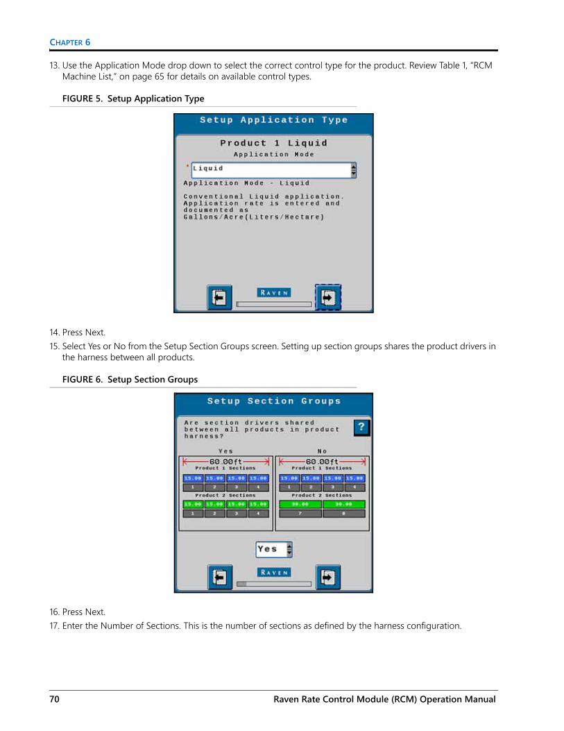
CHAPTER 6
13. Use the Application Mode drop down to select the correct control type for the product. Review Table 1, “RCM Machine List,” on page 65 for details on available control types.
FIGURE 5. Setup Application Type
14. Press Next.15. Select Yes or No from the Setup Section Groups screen. Setting up section groups shares the product drivers in
the harness between all products.
FIGURE 6. Setup Section Groups
16. Press Next.17. Enter the Number of Sections. This is the number of sections as defined by the harness configuration.
70 Raven Rate Control Module (RCM) Operation Manual

AIR CART OPERATION
FIGURE 7. Setup Sections
18. If desired, select Equal Width Sections. This will evenly divide the machine width into equal sections.19. If desired, select Master Clutch. This applies if there is a master clutch on the air cart that will control a magnetic
clutch to engage or disengage the drive.20. If applicable, select the Granular Product Sections Power to Apply checkbox. Select this if the controller will
provide power on the section signal wire when the section is on. Leave unchecked if the controller will provide power to the section signal wire when the section is off.
21. Press Next.22.Select the Starting Section Number for Section Group 1. A section group is a set of sections that will apply the
same product at the same rate.
FIGURE 8. Setup Section Harnessing
23.Enter the Number of Sections for the first section group.24.If desired, select Equal Section Widths.
016-0171-637 Rev. E 71

CHAPTER 6
25. If applicable, enter the Starting Section Number for Section Group 2. In this case, it is five because it must be the first section not being used by the previous section group.
26.Press Next.27.Select the Section Groups for each Product.
FIGURE 9. Setup Section Group Assignment
28.Select Next.29.Review the widths for each section. If needed, select the measurement box next to section and enter a different
width.
FIGURE 10. Setup Section Width
30.Press Next.31. If desired, select a function for the Auxiliary Drivers. Auxiliary drivers are additional switches that provide a 12V
signal to a device.
72 Raven Rate Control Module (RCM) Operation Manual

AIR CART OPERATION
FIGURE 11. Setup Auxiliary Drivers
32.Press Next.33. If desired, select latched for the auxiliary output. Latched means that, once selected, the signal remains
constant until the button is pressed again. Leaving the check box unselected means that the signal is only active when the button is being pressed.
FIGURE 12. Auxiliary Drivers Assignments
34.Press Next.35. Review the Section Summary.
016-0171-637 Rev. E 73

CHAPTER 6
FIGURE 13. Section Summary
36.Press Next.37.Enter the blockage sensor information for each section. The Starting Sensor number must be the next number
after the previous section. In the case below, since section five has twelve sensors, the Starting Sensor number for Section 6 would be 13.
NOTE: Blockage sensor setup is only required when configuring an RBM system.
FIGURE 14. Setup Blockage Sensors
38.Press Next.39.Select the desired scale type from the Scale Setup drop down.
74 Raven Rate Control Module (RCM) Operation Manual
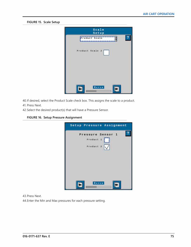
AIR CART OPERATION
FIGURE 15. Scale Setup
40.If desired, select the Product Scale check box. This assigns the scale to a product.41. Press Next.42.Select the desired product(s) that will have a Pressure Sensor.
FIGURE 16. Setup Pressure Assignment
43.Press Next.44.Enter the Min and Max pressures for each pressure setting.
016-0171-637 Rev. E 75

CHAPTER 6
FIGURE 17. Setup Pressure Alarms
45.if desired, select the Alarm? check box to activate alarms.46.Press Next.47.Assign the RPM Sensor for each of the products.
FIGURE 18. Setup RPM Sensor Assignment
48.Press Next.49.Select the Control Valve Type for the first product.
76 Raven Rate Control Module (RCM) Operation Manual

AIR CART OPERATION
FIGURE 19. Setup Control Valve
50.Enter the Valve Response Rate.51. Enter the Control Deadband percentage.52.Enter the Valve Delay value.53.Enter the Valve Advance time.54.Enter the Control Effort percentage.55.Press Next.56.Enter the Flowmeter Calibration number.
FIGURE 20. Setup Rate Sensor
57.Select the Flowmeter Pulse/Units.58.Press Next.59.Enter the Preset Rate Values for each rate.
016-0171-637 Rev. E 77

CHAPTER 6
FIGURE 21. Setup Rates
60.Enter the desired Rate Bump increment.61. Select the Rate Selection.62.Enable Display Smoothing if desired.63.Select the Decimal Shift quantity.64.Press Next.65.Enter the desired Off Rate Alarm percentage.
FIGURE 22. Setup Alarms
66.Enter the Minimum Flow Rate.67.Press Next.68.Review the Setup Summary. If necessary, press Back to adjust the settings.
78 Raven Rate Control Module (RCM) Operation Manual

AIR CART OPERATION
FIGURE 23. Setup Summary
69.Press Next.
AIR CART RUN PAGE OVERVIEWThe image below is an example of a typical run screen.
FIGURE 24. RCM Main Screen
PRODUCT TABSPress on the product tab to select the desired product. This will open the to product run screen for that product.
Auxiliary Drivers
Product Tabs
CurrentProduct Run
Screen
Main
Setup
Totals
Diagnostics
016-0171-637 Rev. E 79

CHAPTER 6
CURRENT PRODUCT RUN SCREENThe current product run screen displays information for the selected product. Each product run screen will vary based on product configuration.
Data Fields display selected settings and can be changed to the operator’s preferences.
FIGURE 25. Air Cart Run Screen
TABLE 3. Air Cart Run Screen Information
Button Description Function/Operation
1 Volume Per Minute Indicates the application rate per minute.
2 Area Per Hour Indicates the how many acres per hour are being applied.
3 PWM Readout Shows the operating percentage of the PWM valve.
4 Traveling Speed Shows the implement/machine speed.
5 Section Switch Box ButtonIndicates if the switch box is on or off:• Green - On• Red - Off
6 Actual Rate Displays the actual application rate.
1
19
3
42
8
10 11
12
6
7
1415
16
17
9
13
5
18
80 Raven Rate Control Module (RCM) Operation Manual

AIR CART OPERATION
7 Target RateDisplays the current target rate. The target rate can be adjusted by pressing in the number cell and entering a new number.
8 Manual/Automatic Toggle Press this to switch between manual and automatic operation.
9 Product On/Off Toggle Press this to manually turn a product on or off.
10 Predefined Rate 1 ButtonSelect this button to start applying at the rate listed on the button. Refer to “Rates Setup” on page 83 for more information on adjusting rates.
11 Predefined Rate 2 ButtonSelect this button to start applying at the rate listed on the button. Refer to “Rates Setup” on page 83 for more information on adjusting rates.
12 Predefined Rate 3 ButtonSelect this button to start applying at the rate listed on the button. Refer to “Rates Setup” on page 83 for more information on adjusting rates.
13 Product Tab Select a tab to view information for that product.
14 Quick Start Button Press the quick start button to quickly configure a product.
15 Master Switch Indicator
The Master Switch Indicator shows the status of the master switch.• Green - On• Red - Off• Orange - Cycle the master switch
16 Tank Level Indicator and Fill Button Indicated the fill level of the tank.
17 Implement Sections
Displays the section number. The section status will display below the implement section.• Red - Off• Green - On• Blue - Liquid
18 Fan Speed Indicates the fan speed in RPM.
19 Meter/Shaft RPM Indicates the shaft or meter RPM as read by an encoder.
Button Description Function/Operation
016-0171-637 Rev. E 81

CHAPTER 6
MAINPress main at any time to return to the Current Product Run Screen.
SETUPPressing setup opens a screen with many tabs.
FIGURE 26. Setup Tabs
APPLICATOR SETUP TABThe Applicator Setup Tab provides options to create a new, edit, or remove an applicator. This tab also provides a summary to the section configuration. For more information on the Precision Farming Setup button, refer to Chapter 9, Precision Farming.
SYSTEM SETTINGSThe system settings provides many buttons that allow the user to modify the current configuration. The table below describes each button in detail.
Applicator Setup
System Setting
Alarms Rates Feature Unlocks
82 Raven Rate Control Module (RCM) Operation Manual

AIR CART OPERATION
TABLE 4. System Settings
ALARM SETTINGSPress the Alarm Settings tab to modify or update alarm settings such as Off Rate Alarm and the Minimum Flow Rate. There is also an option to update the Pressure Alarm.
RATES SETUPThe Rates Setup tab allows the user to adjust the Preset Rate Values, Rate Bump, Rate Selection, and other values entered during the original configuration.
FEATURE UNLOCKSIf there a additional features available for the RCM, enter the provided Activation Key to access these features.
TOTALSThe totals button provides options to access a Current Totals, Device totals, and Distance totals tabs.
Button Description
Control Valve Setup
The Control Valve button allows the user to adjust the following settings for each product:• Valve Response Rate• Control Deadband• Valve Delay• Valve Advance• Control Effort
Rate Sensor Setup
The Rate Sensor Setup button provides the options to adjust the following settings:• Flowmeter Calibration• Flowmeter Pulse/Units• Flowmeter Low Limit• Tank Fill Flowmeter Calibration• Tank Fill Flowmeter Pulse/UnitsThere is also the option to perform a catch test and applied product calibration.
Tank Fill Settings This button allows the user to enter the Tank Capacity, Current Tank Level, and Low Tank Level.
Display Setup Menu The Display Setup Menu allows the user to customize the main run screen object pool.
Pressure Sensor Setup This button allows the user to modify the alarm Min and Max for any products that have pressure alarms selected.
Auxiliary Functions The Auxiliary Functions button allows the user to create new or modify existing auxiliary functions.
Scale Setup Scale Setup allows the user to configure scale options.
016-0171-637 Rev. E 83

CHAPTER 6
DIAGNOSTICSSelecting the Diagnostics button open a window with tabs for the items listed below.
SYSTEM INFORMATIONDisplays information about the RCM including the Hardware Serial Number, Hardware Revision, and Software Version Number.
TESTSThe Tests tab allows the user to select various tests from a dropdown. These list of tests will vary by product configuration.
DIAGNOSTIC TROUBLE CODESThis tab lists Active and Inactive diagnostic trouble codes as well as the ability to Clear the active codes.
SYSTEM SUMMARYDisplays information configured during the setup process but does not provide the option to modify the configuration.
PRODUCT SUMMARYThe Product Summary provides a brief summary for all of the products such as Application Type, Control Valve type, Target Rate, and other settings. This tab does not allow the user to modify the configurations.
AUXILIARY DRIVERSAuxiliary drivers that were created during configuration are listed in Auxiliary Drivers.
FIGURE 27. Auxiliary Drivers
To give the driver a custom name, press in the Driver Name field and, using the keypad, enter the desired name.To activate the auxiliary driver, select the driver number button next to the desired driver.
Driver Number Button
Driver Name Field
84 Raven Rate Control Module (RCM) Operation Manual

CHAPTER7
016-0171-637 Rev. E
CHAPTER 7PLANTER OPERATION
PLANTER MACHINE LISTTABLE 1. RCM Machine List
Machine Type
Application Type Application Mode Application Mode Uses
• Planter • Granular Seed
Planter Section Control
Controller interfaces with up to 16 (Level 1) or 32 (Level 3) planter sections. Multiple row clutches ca be grouped for each section. Seed rate is manually controlled via ground drive transmission.
• Seeder • Granular Seed
Seed Rate Control with Clutches
Controller interfaces with up to 4 hydraulic motor drives for seed rate control and up to 24 planter sections. Multiple row clutches can be grouped for each section.
Seed Rate Control without Clutches
Controller interfaces with up to 16 electric or hydraulic motor drives for seed rate and section control. Multiple rows can be grouped for each hydraulic motor drive.
85

CHAPTER 7
PLANTER SETUPThere are three possible types on planter configurations. There is a wizard section listed below for each possible configuration.
SECTION CONTROLLED PLANTER SETUP1. Select Planter as the machine type.
FIGURE 1. Name Profile
2. Enter the Application Width.3. Press Next.4. Enter the Number of Sections, Row Spacing, and the Number of Rows. The Number of Rows x Row Spacing
must equal the Application Width entered in step 2.
FIGURE 2. Setup Selections
NOTE: The number of total sections depends on task controller capability.5. If you did not select Evenly Divide, enter the number of rows per section. The Planter run screen will open.
86 Raven Rate Control Module (RCM) Operation Manual

PLANTER OPERATION
FIGURE 3. Setup Section Width
SEED RATE CONTROL WITH CLUTCHES PLANTER SETUP6. Select the ECU # from the drop down.
FIGURE 4. Setup System
7. Enter the desired number in the Number or Products field.8. Press Next.9. Select the desired Application Type for the product.
016-0171-637 Rev. E 87

CHAPTER 7
FIGURE 5. Setup Application Type
10. Press Next.11. Select the Application Mode for Product 1.
FIGURE 6. Setup Application Type
12. Press Next.13. Configure the Number of Sections, Row Spacing, Number of Drives, and Number of Rows. If desired, select the
Divide Evenly checkbox to automatically divide the sections widths.
88 Raven Rate Control Module (RCM) Operation Manual

PLANTER OPERATION
FIGURE 7. Setup Sections
14. Press Next.15. Repeat Figure 9 on page 87 through Figure 13 on page 88 for all products.
NOTE: On the Setup Sections Harnessing screen for additional products, enter the next lowest number not being used by the previous section group. For example, if the first product is using the first eight sections, start the second product on section 9.
16. After completing the product configurations, enter the information on the Setup Sections Width screens.
FIGURE 8. Setup Section Width Screens
17. Press Next.18. Select one of the Auxiliary Driver drop downs on the Setup Auxiliary Drivers page. Auxiliary drivers are
additional switches that provide a 12V signal to a device.
016-0171-637 Rev. E 89

CHAPTER 7
FIGURE 9. Setup Auxiliary Drivers
19. Press Next.20.Select the checkbox next to the desired Latched Aux Output. Latched means that, once selected, the signal
remains constant until the button is pressed again. Leaving the checkbox unselected means that the signal is only active when the button is held.
FIGURE 10. Auxiliary Driver Drivers
21. Press Next.22.On the Setup Pressure Sensors page, select the appropriate Pressure Sensors for each product from the
dropdown.
90 Raven Rate Control Module (RCM) Operation Manual

PLANTER OPERATION
FIGURE 11. Setup Pressure Sensors
23.Press Next.24.Use the check boxes on the Setup Pressure Driver screen to select a Product for the first pressure sensor.
FIGURE 12. Setup Pressure Drivers
25.Press Next.26.Repeat Figure 24 on page 91 and Figure 25 on page 91 for all pressure sensors.27. If desired, configure the alarms for each pressure sensor on the Setup Pressure Alarms screen.
016-0171-637 Rev. E 91

CHAPTER 7
FIGURE 13. Setup Pressure Alarms
28.Press Next.29.On the Setup Control Valve page configure the Control Valve Type, Valve Response Rate, and Control
Deadband for the first product. If desired, select the Enable PWM Smart Control checkbox.
FIGURE 14. Setup Control Valve
30.Press Next.31. On the Setup PWM page, configure the Coil Frequency, PWM High Limit, PWM Low Limit, and PWM Startup
for the first product.
92 Raven Rate Control Module (RCM) Operation Manual

PLANTER OPERATION
FIGURE 15. Setup PWM
32.Press Next.33.Configure the Seeds/Revolution, Motor/Meter Ratio, and Pulses/Revolution on the first Setup Rate Sensor
Page.
FIGURE 16. Setup Rate Sensor
34.Press Next.35.Enter the Preset Rate Values, Rate Bump, and Rate Selection on the Setup Rates page. If desired, select the
Display Smoothing Checkbox.
016-0171-637 Rev. E 93

CHAPTER 7
FIGURE 17. Setup Rates
36. If desired, enter the Off Rate Alarm percentage and enable the Alarm checkbox.
FIGURE 18. Setup Alarms
37.Press Next.38.Repeat Figure 29 on page 92 through Figure 37 on page 94 for each product. Product configuration will vary
depending on application type.39.After all products are configures, a Setup Summary page will open displaying information about the
configuration. If needed, press back to adjust the configurations. If the setup seems correct, press Next. The run page home screen will open. For additional formation on the run page, refer to “Planter Run Page Overview” on page 104.
94 Raven Rate Control Module (RCM) Operation Manual

PLANTER OPERATION
SEED RATE CONTROL WITHOUT CLUTCHES PLATER SETUP1. Select Planter from the dropdown on the Select Profile Page.
FIGURE 19. Name Profile
2. Press Next.3. Select the ECU # from the dropdown.
FIGURE 20. Setup System
4. Enter the desired number in the Number or Products cell.5. Press Next.6. Select the desired Application Type for the product.
016-0171-637 Rev. E 95

CHAPTER 7
FIGURE 21. Setup Application Type
7. Press Next.8. Select the Application Mode for Product 1.
FIGURE 22. Setup Application Type
9. Press Next.10. Configure the Number of Sections, Row Spacing, Number of Drives, and Number of Rows. If desired, select the
Divide Evenly checkbox to automatically divide the sections widths.
96 Raven Rate Control Module (RCM) Operation Manual

PLANTER OPERATION
FIGURE 23. Setup Sections
11. Press Next.12. If necessary, select the Application Mode for additional products.13. Press Next.14. On the Setup Section Groups screen, select the Number of Section Groups from the dropdown.
FIGURE 24. Setup Section Groups
15. Press Next.16. Review the information on the Setup Section Harnessing screen.17. Press Next.18. On the Setup Section Harnessing screen, enter the Starting Section Number, Number of Sections, and select
Equal Section Widths (if desired).
016-0171-637 Rev. E 97

CHAPTER 7
FIGURE 25. Setup Section Harnessing
19. Press Next.20.Select the Section Group assignment for each product from the dropdown on the Setup Section Group
Assignment screen.
FIGURE 26. Setup Section Group Assignment
21. Press Next.22.After completing the product configurations, enter the information on the Setup Sections Width screens.
98 Raven Rate Control Module (RCM) Operation Manual

PLANTER OPERATION
FIGURE 27. Setup Section Width Screens
23.Press Next.24.If desired, select Setup Auxiliary Drivers. Auxiliary drivers are additional switches that provide a 12V signal to a
device.
FIGURE 28. Setup Auxiliary Drivers
25. Press Next.26.Select the checkbox next to the desired Latched Aux Output. Latched means that, once selected, the signal
remains constant until the button is pressed again. Leaving the checkbox unselected means that the signal is only active when the button is held.
016-0171-637 Rev. E 99

CHAPTER 7
FIGURE 29. Auxiliary Driver Assignments
27.Press Next.28.On the Setup Pressure Sensors page, select the appropriate Pressure Sensors for each product from the
dropdown.
FIGURE 30. Setup Pressure Sensors
29.Press Next.30.Use the check boxes on the Setup Pressure Assignment screen to select a Product for the first pressure Sensor.
100 Raven Rate Control Module (RCM) Operation Manual

PLANTER OPERATION
FIGURE 31. Setup Pressure Assignments
31. Press Next.32.Repeat Figure 24 on page 91 and Figure 25 on page 91 for all pressure sensors.33. If desired, configure the alarms for each pressure sensor on the Setup Pressure Alarms screen.
FIGURE 32. Setup Pressure Alarms
34.Press Next.35.On the Setup Control Valve page configure the Control Valve Type, Valve Response Rate, and Control
Deadband for the first product. If desired, select the Enable PWM Smart Control checkbox.
016-0171-637 Rev. E 101

CHAPTER 7
FIGURE 33. Setup Control Valve
36.Press Next.37.On the Setup PWM page, configure the Coil Frequency, PWM High Limit, PWM Low Limit, and PWM Startup
for the first product.
FIGURE 34. Setup PWM
38.Press Next.39.Configure the Seeds/Revolution, Motor/Meter Ratio, and Pulses/Revolution on the first Setup Rate Sensor
Page.
102 Raven Rate Control Module (RCM) Operation Manual

PLANTER OPERATION
FIGURE 35. Setup Rate Sensor
40.Press Next.41. Enter the Preset Rate Values, Rate Bump, and Rate Selection on the Setup Rates page. If desired, select the
Display Smoothing Checkbox.
FIGURE 36. Setup Rates
42.If desired, enter the Off Rate Alarm percentage and enable the Alarm checkbox.
016-0171-637 Rev. E 103

CHAPTER 7
FIGURE 37. Setup Alarms
43.Press Next.44.Repeat Figure 29 on page 92 through Figure 37 on page 94 for each product. Product configuration will vary
depending on application type.45.After all products are configured, a Setup Summary page will open displaying information about the
configuration. If needed, press back to adjust the configuration. If the setup seems correct, press Next. The run page home screen will open. For additional information on the run page, refer to “Planter Run Page Overview” on page 104.
PLANTER RUN PAGE OVERVIEWThe image below is an example of a typical run screen.
FIGURE 38. Planter Run Screen
Auxiliary Drivers
Product Tabs
Current Product Run Screen
Main
Setup
Totals
Diagnostics
104 Raven Rate Control Module (RCM) Operation Manual

PLANTER OPERATION
PRODUCT TABSPress on the product tab to select the desired product. This will open the to product run screen for that product.
CURRENT PRODUCT RUN SCREENThe current product run screen displays information for the selected product. Each product run screen will vary based on product configuration.
Data Fields display selected settings and can be changed to the operator’s preferences.
FIGURE 39. Planter Run Screen
118
3
42
8
10 11
12
67
1415
1617
913
5
19
016-0171-637 Rev. E 105

CHAPTER 7
TABLE 2. Planter Run Screen Information
Button Description Function/Operation
1 Voltage Indicates the current duty cycle.
2 Injection Pressure Indicates the injection pressure.
3 Seed Level Displays the current bin level.
4 Acres Applied Displays the number of acres applied since starting the job.
5 Section Switchbox Button
Indicates if the switch box is on or off:• Green - On• Red - OffPress the switch box button to navigate to a screen that allows the user to turn off the switch boxes for individual sections.
6 Actual Rate Displays the actual application rate.
7 Target Rate
Displays the current target rate. The target rate can be adjusted by pressing in the number cell and entering a new number.
8 Manual/Automatic TogglePress this to switch between manual and automatic operation.
9 Product On/Off Toggle Press this to manually turn a product on or off.
10 Rate Bump DownPress this to decrease the application rate at the increment set during configuration.
11 Rate Bump UpPress this to increase the application rate at the increment set during configuration.
12 Application RateDisplays the current application speed in acres per hour.
13 Product Tab Select a tab to view information for that product.
106 Raven Rate Control Module (RCM) Operation Manual

PLANTER OPERATION
MAINPress main at any time to return to the Current Product Run Screen.
SETUPPressing setup opens a screen with many tabs.
14 Quick Start Button Press the quick start button to quickly configure a product.
15 Master Switch Indicator
The Master Switch Indicator shows the status of the master switch.• Green - On• Red - Off• Orange - Cycle the master
switch
16 Row Number Displays the ending row number for the section.
17 Row IndicatorDisplays the row status.• Gray - Off• Green - On
18 Meter Spread High and Low Indicates the meter spread speed in RPM.
19 Traveling Speed Shows the implement/machine speed.
Button Description Function/Operation
016-0171-637 Rev. E 107

CHAPTER 7
FIGURE 40. Setup Tabs
APPLICATOR SETUP TABThe Applicator Setup Tab provides options to create a new, edit, or remove an applicator. This tab also provides a summary to the section configuration. For more information on the Precision Farming Setup button, refer to Chapter 9, Precision Farming.
SYSTEM SETTINGSThe system settings provides many buttons that allow the user to modify the current configuration. The table below describes each button in detail.
Applicator Setup
System Setting Alarms Rates Feature
Unlocks
108 Raven Rate Control Module (RCM) Operation Manual

PLANTER OPERATION
TABLE 3. System Settings
ALARM SETTINGSPress the Alarm Settings tab to modify or update alarm settings such as Off Rate Alarm and the Minimum Flow Rate. There is also an option to update the Pressure Alarm.
RATES SETUPThe Rates Setup tab allows the user to adjust the Preset Rate Values, Rate Bump, Rate Selection, and other values that were entered during the original configuration.
FEATURE UNLOCKSIf there a additional features available for the RCM, enter the provided Activation Key to access these features.
TOTALSThe totals button provides options to access a Current Totals, Device totals, and Distance totals tabs.
Button Description
Control Valve Setup
The Control Valve button allows the user to adjust the following settings for each product: • Valve Response Rate• Control Deadband• Valve Delay• Valve Advance• Control Effort
Rate Sensor Setup
The Rate Sensor Setup button provides the options to adjust the following settings: • Flow meter Calibration• Flow meter Pulse/Units• Flow meter Low Limit• Tank Fill Flow meter Calibration• Tank Fill Flow meter Pulse/UnitsThere is also the option to perform a catch test and applied product calibration.
Tank Fill Settings This button allows the user to enter the Tank Capacity, Current Tank Level, and Low Tank Level.
Display Setup Menu Use the Display Setup Menu to add buttons, remove buttons, or reorganize the main run screen.
Pressure Sensor Setup This button allows the user to modify the alarm Min and Max for any products that have pressure alarms selected.
Auxiliary Functions The Auxiliary Functions button allows the user to create new or modify existing auxiliary functions.
Scale Setup Scale Setup allows the user to configure scale options.
016-0171-637 Rev. E 109

CHAPTER 7
DIAGNOSTICSSelecting the Diagnostics button open a window with tabs for the items listed below.
SYSTEM INFORMATIONDisplays information about the RCM including the Hardware Serial Number, Hardware Revision, and Software Version Number.
TESTSThe Tests tab allows the user to select various tests from a dropdown. These list of tests will vary by product configuration.
DIAGNOSTIC TROUBLE CODESThis tab lists Active and Inactive diagnostic trouble codes as well as the ability to Clear the active codes.
SYSTEM SUMMARYDisplays information configured during the setup process but does not provide the option to modify the configuration.
PRODUCT SUMMARYThe Product Summary provides a brief summary for all of the products such as Application Type, Control Valve type, Target Rate, and other settings. This tab does not allow the user to modify the configurations.
AUXILIARY DRIVERSAuxiliary drivers that were created during configuration are listed in Auxiliary Drivers.
FIGURE 41. Auxiliary Drivers
To give the driver a custom name, press in the Driver Name field and, using the keypad, enter the desired name.To activate the auxiliary driver, select the driver number button next to the desired driver.
Driver Number Button
Driver Name Field
110 Raven Rate Control Module (RCM) Operation Manual

CHAPTER8
016-0171-637 Rev. E
CHAPTER 8STAND ALONE SCALE OPERATION
SCALE MACHINE LIST
STAND ALONE SCALE OPERATION1. Select Scale as the Machine Type.
FIGURE 1. Name Profile
2. Enter a Profile Name.3. Press Next.4. Select the check box(es) next to the desired Scale(s) you want to monitor.
TABLE 1. RCM Machine List
Machine Type
Application Type Application Mode Application Mode Uses
• Scale • NA NA NA
111

CHAPTER 8
FIGURE 2. Scale Setup
5. If desired, select the Total Scale checkbox to monitor the weight of all the selected scales combined.6. Press Next.7. Enter the Scale Total Calibration Number.
FIGURE 3. Scale Setup
8. Press Next.9. Review the scale configuration on the Setup Summary page.
112 Raven Rate Control Module (RCM) Operation Manual

STAND ALONE SCALE OPERATION
FIGURE 4. Setup Summary
10. If any of the information is correct, press back to adjust the configuration. If the configuration is correct, press Next.
SCALE RUN PAGE OVERVIEWThe image below is an example of a typical run screen.
FIGURE 5. RCM Main Screen
SCALE SCREENThe scale screen displays graphic and numeric representations of the scales as well as options to zero a scale or view the current gross scale weight.
Auxiliary Assignments
Scale Screen
Main
Setup
Totals
Diagnostics
016-0171-637 Rev. E 113

CHAPTER 8
CURRENT PRODUCT RUN SCREENThe current product run screen displays information for the selected product. Each product run screen will vary based on product configuration.
Data Fields display selected settings and can be changed to the operator’s preferences.
FIGURE 6. Air Cart Run Screen
1
3
4
2
5
6
114 Raven Rate Control Module (RCM) Operation Manual

STAND ALONE SCALE OPERATION
TABLE 2. Scale Run Screen Information
MAINPress main at any time to return to the Current Product Run Screen.
SETUPPressing setup opens a screen with many tabs.
Button Description Function/Operation
1 Scale SelectionPress these buttons along to the to switch between the different scales.
2 Weight Displays the current weight on the selected scale.
3 Tare
Press the Tare button to zero out the selected scale. If the combined weight scale is selected this will display as Zero.
4 Scale GraphicsShows a graphical representation of the weight of teach scale.
5 GrossDisplays the weight on the scale. If the combined weight scale is selected this will display as Net.
6 Combined Weight Displays the combined weight of all the scales.
016-0171-637 Rev. E 115

CHAPTER 8
FIGURE 7. Setup Tabs
APPLICATOR SETUP TABThe Applicator Setup Tab provides options to create a new, edit, or remove an applicator. This tab also provides a summary to the section configuration.
SYSTEM SETTINGSThe system settings provides many buttons that allow the user to modify the current configuration. The table below describes each button in detail.
Applicator Setup
System Setting
Feature Unlocks
116 Raven Rate Control Module (RCM) Operation Manual

STAND ALONE SCALE OPERATION
TABLE 3. System Settings
FEATURE UNLOCKSIf there a additional features available for the RCM, enter the provided Activation Key to access these features.
TOTALSThe totals button provides options to access a Current Totals, Device totals, and Distance totals tabs.
DIAGNOSTICSSelecting the Diagnostics button open a window with tabs for the items listed below.
SYSTEM INFORMATIONDisplays information about the RCM including the Hardware Serial Number, Hardware Revision, and Software Version Number.
TESTSThe Tests tab allows the user to select various tests from a dropdown. These list of tests will vary by product configuration.
Button Description
Control Valve Setup
The Control Valve button allows the user to adjust the following settings for each product:• Valve Response Rate• Control Deadband• Valve Delay• Valve Advance• Control Effort
Rate Sensor Setup
The Rate Sensor Setup button provides the options to adjust the following settings: • Flowmeter Calibration• Flowmeter Pulse/Units• Flowmeter Low Limit• Tank Fill Flowmeter Calibration• Tank Fill Flowmeter Pulse/UnitsThere is also the option to perform a catch test and applied product calibration.
Tank Fill Settings This button allows the user to enter the Tank Capacity, Current Tank Level, and Low Tank Level.
Display Setup Menu The Display Setup Menu allows the operator to configure the main run screen.
Pressure Sensor Setup This button allows the user to modify the alarm Min and Max for any products that have pressure alarms selected.
Auxiliary Functions The Auxiliary Functions button allows the user to create new or modify existing auxiliary functions.
Scale Setup Scale Setup allows the user to configure scale options.
016-0171-637 Rev. E 117

CHAPTER 8
DIAGNOSTIC TROUBLE CODESThis tab lists Active and Inactive diagnostic trouble codes as well as the ability to Clear the active codes.
SYSTEM SUMMARYDisplays information configured during the setup process but does not provide the option to modify the configuration.
PRODUCT SUMMARYThe Product Summary provides a brief summary for all of the products such as Application Type, Control Valve type, Target Rate, and other settings. This tab does not allow the user to modify the configurations.
AUXILIARY ASSIGNMENTSAuxiliary assignments that were created during configuration are listed in Auxiliary Assignments.
FIGURE 8. Auxiliary Assignments
To give the driver a custom name, press in the Driver Name field and, using the keypad, enter the desired name.
To activate the auxiliary driver, select the driver number button next to the desired driver.
Driver Number Button
DriverNameField
118 Raven Rate Control Module (RCM) Operation Manual

CHAPTER9
016-0171-637 Rev. E
CHAPTER 9PRECISION FARMING
Precision farming allows the user to modify configurations that may not be available through the field computer.
IMPORTANT: Depending on the field computer, these settings may or may not be implemented.
To adjust precision farming settings after performing a machine configuration:1. Press Setup.
FIGURE 1. RCM Settings
2. Select Precision Farming Setup.3. Review the information on the Section Setup Wizard screen then press Next.
119
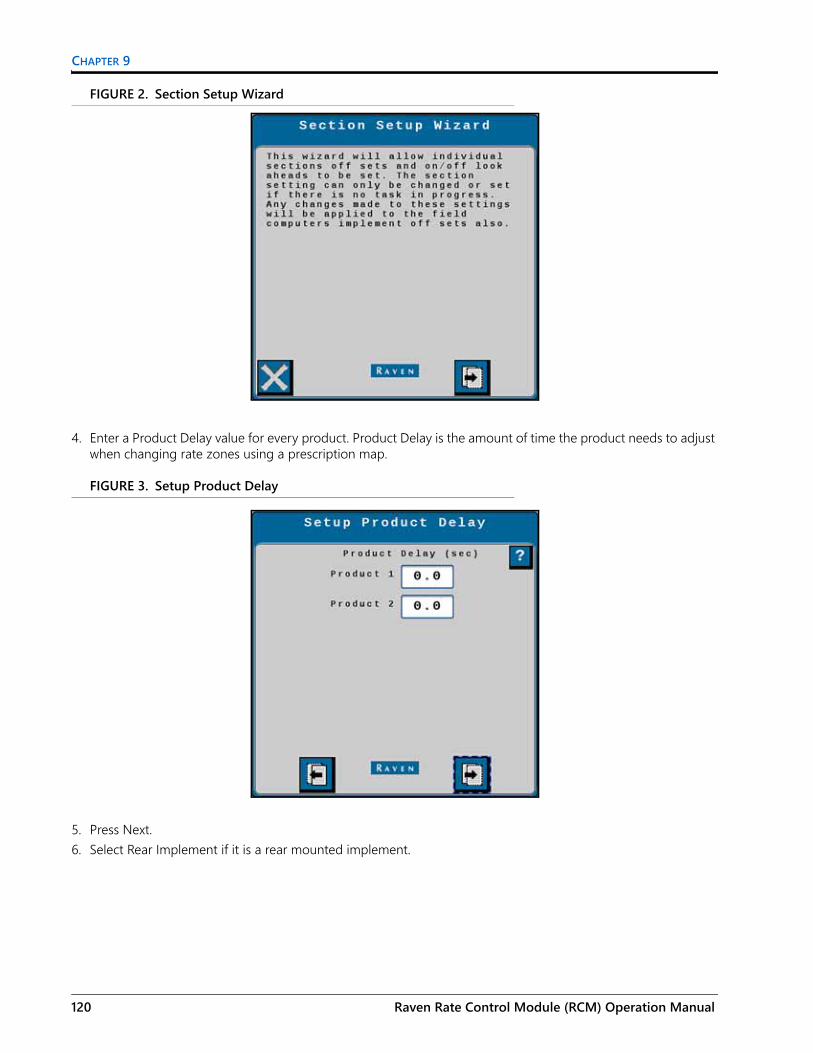
CHAPTER 9
FIGURE 2. Section Setup Wizard
4. Enter a Product Delay value for every product. Product Delay is the amount of time the product needs to adjust when changing rate zones using a prescription map.
FIGURE 3. Setup Product Delay
5. Press Next.6. Select Rear Implement if it is a rear mounted implement.
120 Raven Rate Control Module (RCM) Operation Manual
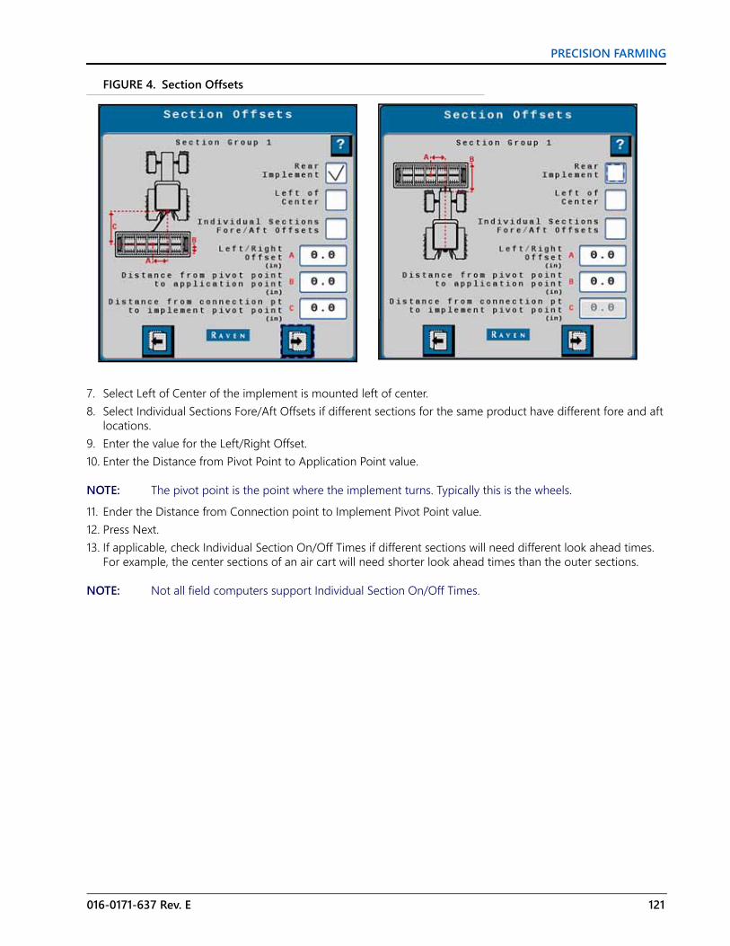
PRECISION FARMING
FIGURE 4. Section Offsets
7. Select Left of Center of the implement is mounted left of center.8. Select Individual Sections Fore/Aft Offsets if different sections for the same product have different fore and aft
locations.9. Enter the value for the Left/Right Offset.10. Enter the Distance from Pivot Point to Application Point value.
NOTE: The pivot point is the point where the implement turns. Typically this is the wheels.11. Ender the Distance from Connection point to Implement Pivot Point value.12. Press Next.13. If applicable, check Individual Section On/Off Times if different sections will need different look ahead times.
For example, the center sections of an air cart will need shorter look ahead times than the outer sections.
NOTE: Not all field computers support Individual Section On/Off Times.
016-0171-637 Rev. E 121

CHAPTER 9
FIGURE 5. Section Turn On/Off Times
14. Press Next.15. If Individual Section On/Off Times was selected, configure the Section Turn On/Off Times for the Section
Group. If not, skip to step 16.
FIGURE 6. Section Turn On/Off Times
16. Press Next.17. If applicable, enter the offset values for individual sections. If the section is located in front of the implement
pivot point, enter it as a negative value.
122 Raven Rate Control Module (RCM) Operation Manual

PRECISION FARMING
FIGURE 7. Individual Fore/Aft Offsets
18. Press Next.19. Repeat step 6 through step 18 for all section groups.20.After configuration is complete, press Next and the Application Setup screen will display again.
016-0171-637 Rev. E 123

CHAPTER 9
124 Raven Rate Control Module (RCM) Operation Manual

CHAPTER10
016-0171-637 Rev. E
CHAPTER 10TROUBLESHOOTING
ACCESSING SYSTEM INFORMATION1. Select the Diagnostics button.2. Select the System Information tab.
3. Select the desired page from the drop-down.
Option Description
Hardware/Software Displays the manufacturer’s information for the Raven Rate Control Module hardware and software.
Switchbox Displays if an external switchbox is present and the status of the switches.Delivery System Shows application information for the selected product.Section Status Shows if each section valve is currently open or closed.System Voltages Shows voltage and current information for the Raven Rate Control Module.Working Parameters Displays the implement width, current speed, and speed source.Switches/Status Displays the status of the Master switch.Pressure Sensors Displays voltage and pressure information for each pressure sensor.Bin Level Sensors Displays whether each bin level sensor is covered or uncovered.RPM Sensors Shows the signal detected by each RPM sensor.Tank Fill Monitor Displays the fill rate and volume detected by the tank fill monitor.Task Totals Shows the area covered and volume applied for the current task.
125

CHAPTER 10
GENERAL TROUBLESHOOTING
Symptom Problem SolutionUnexpected application rate.
Incorrect rate type selected (gal/min or gal/acre). Select the correct rate type.
Product does not shut off. Valve does not respond to commands. Select the correct valve type.
2-Wire valve selection is not available.
Dual boom is selected. Disable dual boom.More than seven sections are selected. Assign fewer than eight sections.
Implement section is not turning on or off. Incorrect section valve type selected. Select correct section valve type.
Application is erratic. Calibration number is not set correctly. Enter the correct calibration number.Trouble code is displayed for high pressure.
System pressure is too high. Select flow return in the system setup.
Trouble code is displayed for unexpected flow.
Constant flow is disabled when using a constant flow system with boom valve closed.
Select constant flow in system setup.
Flow is not applying at desired rate.
Incorrect application rate. Ensure 10 gal/10L unit is used.Minimum Flow rate feature causes over-application in areas where machine speed is low enough to activate Minimum Flow Rate.
Set minimum flow rate to zero to disable feature.
System detects implement is down for an extensive period of time.
Height switch is disabled.If height switch indicator does not match machine operation, service height switch.
Unexpected chemical flow detected.
Controller attempts to close section valves, but detects flow on a sprayer or liquid fertilizer system.
Shut off solution pump.
Unable to setup minimum and maximum alarms.
Minimum and maximum alarms are disabled.
Ensure pressure sensor is installed and configured.
Unable to set values. System not allowing changes values or settings. Ensure Master Switch is off.
Unexpected anhydrous ammonia flow detected.
Controller attempts to close On/Off valve, but still detects flow. Select button to turn off control valve.
Controller attempts to close all valves, but still detects flow.
Follow instructions on Warning page on display.
Pressure sensors are not configured. Pressure sensor 2 is not an option. Ensure both sensors are configured.
Not able to activate system. Master Switch indicator is orange. Cycle master switch.
Unwanted minimum flow rate activation. Over application in low speed areas. Set minimum flow rate to zero to
disable function.
126 Raven Rate Control Module (RCM) Operation Manual

TROUBLESHOOTING
TESTS1. Navigate to the Raven Rate Control Module.2. Select Diagnostics button.3. Select the Tests tab.
4. Select the test from the drop-down menu.a. Liquid Diagnostics Test Warning displays after selecting any of the following liquid application:
• Nozzle Flow Check• Rinse Cycle• Control/Section Test• Control Valve Test• Calibrate PWM Limits
b. NH3 Diagnostics Test Warning displays after selecting any of the following for NH3 applications:• Energize System
016-0171-637 Rev. E 127

CHAPTER 10
• Bleed System Test
NOTE: The bleed system test will not evacuate all of the NH3 entirely. Perform the manual bleed procedure for the system to ensure NH3 is completely evacuated.
c. Dry Diagnostic Test Warning displays after selecting any of the following for dry applications:• Granular Flow Check• Spreader/Air Cart Check• Control/Section Test• Calibrate PWM Limit• Bin/Tank Cleanout
5. Read the Discharge Warning and select Accept.
NOZZLE FLOW CHECKIMPORTANT: Always fill solution tank with clean water to perform nozzle flow check.
NOTE: Enter conditions that are comparable to normal operation. Larger dispensed volumes result in longer but more accurate calibration tests.
Perform Nozzle Flow Check to test an application rate at a desired speed without the machine moving. The following items can be determined:• If actual application rate meets the target application rate at a given speed.• The actual flow rate of an implement section.
128 Raven Rate Control Module (RCM) Operation Manual

TROUBLESHOOTING
• Whether the nozzles are worn.• Spray control valve pressure at a desired speed and application rate.
NOTE: Turn the master switch off or leave Diagnostics at any time to cancel the test.
Speed and rate can be changed while the test is running.1. Enter a Test Speed and Rate.
2. Turn the master switch on.3. Select Start.
If the volume is higher than expected and pressure is lower than expected, nozzle tips could be worn.
If pressure is higher than expected for the given output, nozzle tips could be partially plugged. Pressure drops can occur between section shutoff valves and nozzle tips. This is normally only associated with high flow rates.
RINSE CYCLEIMPORTANT: Always fill the solution tank with clean water to perform the rinse cycle.
Rinse Cycle test fully opens all sections, fence row valves, and flow control valve until the flow meter detects reduced flow.
NOTE: Turn the master switch off or leave Diagnostics at any time to cancel the test.
1. Turn the master switch on.
016-0171-637 Rev. E 129

CHAPTER 10
2. Select Start.
CONTROL/SECTION TESTSelected sections open while the test is in progress. Unselected sections remain closed.
NOTE: Turn the master switch off or leave Diagnostics at any time to cancel the test.1. Enable the desired sections.2. Turn the master switch on.
3. Select Start.4. Toggle section on or off using the buttons.5. Press and hold - or + to operate the control valve.
CONTROL VALVE TESTThis test operates control valve without dispensing product.
NOTE: Turn the master switch on or leave the Diagnostics at any time to leave the test.
1. Select Start.2. Press and hold - or + to operate the control valve.
130 Raven Rate Control Module (RCM) Operation Manual

TROUBLESHOOTING
CALIBRATE PWM LIMITSNOTE: Turn master switch off or leave Diagnostics at any time to cancel the test.1. Turn the master switch on.
2. Press Start.3. Press and hold - or + buttons until the minimum acceptable flow/pressure is achieved.4. Select Set Low Limit.5. Press and hold the - or + buttons until the maximum acceptable flow/pressure is achieved.6. Select Set High Limit.
ENERGIZE SYSTEMNOTE: Turn the master switch off or leave diagnostics page to immediately force the valves to return to the
closed position and stop flow.
Use the Energize System procedure to test for flow at openers, purge air and vapor from the NH3 delivery system, and fill cooler and hoses with liquid anhydrous. Select Start to fully open the control valve and section valves for a few seconds and then automatically close the valves.1. Ensure the area is clear of people, pets, and livestock.2. Position the machine into the wind.3. Turn the master switch on.
4. Select the Override Height Switch checkbox.5. Select Start. The valves will stay open for a few seconds.
016-0171-637 Rev. E 131

CHAPTER 10
6. Repeat the procedure if needed.
BLEED SYSTEM TESTNOTE: Turn the master switch off or leave diagnostics page to immediately force the valves to return to the
closed position and stop flow.
The Bleed System Test allows the operator to bleed trapped anhydrous ammonia from high-pressure lines between section valves and control valves while remaining seated in the cab.1. Bleed and disconnect the nurse tank and supply lines.2. Ensure that the area is clear of people, pets, and livestock.3. Position the machine into the wind.4. Enable the desired sections.
5. Select the Override Height Switch checkbox.6. Select Start.7. Toggle the sections as needed.
NOTE: Turn the master switch on or leave the Diagnostics at any time to leave the test.
SPREADER/AIR CART CHECKNOTE: Turn the master switch off or leave Diagnostics at any time to cancel test.
132 Raven Rate Control Module (RCM) Operation Manual

TROUBLESHOOTING
1. If the system is configured with an RPM assignment, the RPM assignment will be disabled for this test. If desired, select the Enable RPM Products check box.
2. Enter the Test Speed and Rate.
3. Turn the master switch on.4. Select Start.
BIN/TANK CLEANOUTNOTE: Turn the master switch off or leave Diagnostics at any time to cancel the test.1. Select Product bins or tanks to be cleaned out.
2. Turn the master switch on.
016-0171-637 Rev. E 133

CHAPTER 10
3. Select Start.
DEMONSTRATION MODEDemonstration Mode provides a bench top simulation only. It is not intended for use on actual equipment.1. Select Demonstration Mode from the Tests tab. A warning prompt will appear.2. Read the warning and either select Cancel or Accept.
3. After the Demonstration Mode screen opens, select the Flow Simulation type.• None: No flow will be simulated.• Fixed Freq: If Fixed Frequency is selected a Fixed Flow box will appear. Enter the desired flow value
in the box.• Rate Tracking: The system will adjust flow so it matches the flow required to achieve the target
application rate entered on the main screen.
4. Enter a simulated pressure value for pressure sensors 1, 3, and 5. Enable the checkbox.5. Enter a simulated pressure value for pressure sensors 2, 4 and 6. Enable the checkbox.
DIAGNOSTIC LOOP BACK TESTLoop back tests provide a way to self-test the Raven Rate Controller. There are two loop back tests available.
• ECU Test: The ECU Test performs a test of the Raven Rate Controller Module.
134 Raven Rate Control Module (RCM) Operation Manual

TROUBLESHOOTING
• 47 Pin: The 47 Pin test performs a test of the Raven Rate Controller Module and the cabling and pins of the product cable. This test requires a 47 pin loop back tester.
To perform a Diagnostic Loop back Test:1. Ensure the Master Switch is off and the 47-pin plug of the product cable is disconnected.2. Select the Tests tab.
3. Select Diagnostics Loop Back Test from the test selection drop down.4. Press Begin. A Warning window will open checking if the product cable is disconnected.
5. Press Accept to continue or Cancel to exit the test. After pressing Accept, the Diagnostic Loop Back Test window will open.
6. Review the information on the Diagnostic Loop Back Test.
Tests
Test Selection
Begin
Accept
Cancel
016-0171-637 Rev. E 135

CHAPTER 10
7. Select the desired test (47 Pin or ECU Test) from the Test Selection drop down.8. If desired, select the checkbox by Continuous Test. This checkbox will make the test run repeatedly until the
Stop button is pressed.9. After the desired test is selected, press Start. The Diagnostic Loop Back Test progress window will open. This
window shows the test status and the number of tests that Pass or Fail. If the Continuous Test checkbox was not selected the test will run one time. If the Continuous Test checkbox was selected, the test will repeat until the Stop button is pressed.
NOTE: The Start button will be grayed out if the product cable is connected or the master switch is on. Fix the issue to start the test.
10. If a failure is detected a Loop Back Failure Alert window will open. After reviewing the information of the Alert, select Accept.
136 Raven Rate Control Module (RCM) Operation Manual

TROUBLESHOOTING
11. After the loop back test is complete, press Accept to return to the test selection window. To exit the loop back test, select the cancel button.
12. Select the Accept button to exit the test or Cancel to return to the test.13. Select the desired object pool.
DIAGNOSTIC LEDSThere are four LEDs on the front of the ECU, labeled with the power symbol, A, B, and C. Each LED’s color and blink rate indicates different information as detailed in the table below. If multiple states are true for a given LED the first active state listed in the table will be the state displayed. After addressing the displayed state (if needed), the next LED state will be indicated.
Accept
Cancel
016-0171-637 Rev. E 137

CHAPTER 10
FIGURE 1. Raven Rate Controller LEDs
LED Main App Controlled Color Blinks Per
Second Status Name Description
Power No GREEN Solid ECU powered Active when ECU has power
A
No OFF Solid Microprocessor OffActive when the microprocessor is not powered
No ANY Solid System FaultActive when the microprocessor has stopped functioning
No YELLOW 1 Boot Hold ModeActive when the boot loader enters boot hold mode
No RED 5 Programming Microprocessor
Active when the microprocessor is being programmed
Yes RED 1 ISOBUS Offline Active if the ISOBUS is offline
Yes WHITE 1 UT Offline Active if the UT is offline
Yes PURPLE 1 Loop back Test Mode Loop back test mode enabled
Yes GREEN 1 Systems Normal Active when linked with UT and system is normal
AB
C
Power
138 Raven Rate Control Module (RCM) Operation Manual

TROUBLESHOOTING
B
No RED Solid FPGA not running PCB subsystem not running (FPGA)
Yes RED 1 ECU Power Loss System has lost ECU power
Yes BLUE 1 Rate Sensor Signal Present Signal is present on 1 or more rate sensors
Yes YELLOW 1 DTC Active One or more DTCs are active
Yes WHITE 1 System Under Voltage System voltage is below 11.5 volts
Yes PURPLE 1 System Over Voltage System voltage is above 16 volts
Yes BLUE Solid Product EnabledOne or more product switches have been set to On
Yes PURPLE Solid RPM Signal Present Signal is present on one or more RPM sensors
Yes GREEN Solid All Products Disabled All product switches have been set to Off
Yes RED Solid Current loopback test sequence failure
One or more loop back subtests failed in this current test sequence
Yes YELLOW Solid Previous loop back test sequence failure
One or more loop back subtests failed in the previous test sequence
Yes GREEN Solid No loop back subtests have failed
No loop back subtests have failed
C
No RED Solid FPGA not running PCB subsystem not running (FPGA)
Yes BLUE 1 Bluetooth Command Bluetooth command has been received
Yes BLUE Solid Bluetooth Comm Active Bluetooth communication is active
Yes GREEN 1 Aux CAN Active The Auxiliary CAN channel is active
Yes RED 1 Aux CAN Comm LostActive if the Auxiliary CAN channel was active and is now offline
Yes GREEN Solid LED C Functional - No ErrorLED C is functional and there are no other LED C states to report
Yes PURPLE Solid Loop back test in progress A loop back test is in progress
Yes GREEN Solid Loop back test not in progress
A loop back test is not in progress
LED Main App Controlled Color Blinks Per
Second Status Name Description
016-0171-637 Rev. E 139

CHAPTER 10
OUTPUTS TABLE - SINGLE PRODUCTNOTE: Enabling optional features, such as fence row nozzles and agitators reduces the number of section
controls.
Output Number
3-Wire Section Valves
2-Wire Section Valves NH3 Tool Tiered Boom
Applications1 Section 1 Section 1 (+) Section 1 Section 12 Section 2 Section 1 (+) Section 2 Section 23 Section 3 Section 2(+) Section 3 Section 34 Section 4 Section 2 (-) Section 4 Section 45 Section 5 Section 3 (+) Section 5 Section 56 Section 6 Section 3 (-) Section 6 Section 67 Section 7 Section 4 (+) Section 7 Section 78 Section 8 Section 4 (-) Section 8 Section 8
9 Section 9Section 5 (+) or agitator valve (+)
Boom pump (+) Section 9
10 Section 10 Section 5 (-) or agitator valve (-) Boost pump (-) Section 10
11 Section 15 or agitator value
Section 6 (+) or left fence row
Section 15 or agitator valve
12 Section 16 or flow return (+)
Section 6 (-) or right fence row
Section 16 or flow return (+)
13 Flow return (-) or left fence row
Section 7 (+) or flow return valve (-)
Master on-off valve
Section 17, tier 1 solenoid signal, flow return (-), or right fence row
14 Right fence rowSection 7 (-) or flow return valve (+)
Section 18, tier 2 solenoid signal, or left fence row
15 Control valve (+) Control valve (+) Control valve (+) Control valve (+)16 Control valve (-) Control valve (-) Control valve (-) Control valve (-)17 Section 11 Section 1118 Section 12 Section 1219 Section 13 Section 1320 Section 14 Section 14212223 Section 19
24 Fast control valve power Section 20
25 Flow return (+)Section 8 (+) or agitator valve B (+)
Flow return (+)
140 Raven Rate Control Module (RCM) Operation Manual

TROUBLESHOOTING
OUTPUTS TABLE - MULTIPLE PRODUCTSNOTE: Enabling optional features, such as fence row nozzles and agitators reduces the number of section
controls.
26 Flow return (-)Section 8 (-) or agitator valve b (-)
Flow return (-)
27 Section 928 Agitator valve Section 10 Agitator valve29 Right fence row Right fence row Right fence row30 Left fence row Left fence row Left fence row3132
Output Number NH3 Tool Spreader Air Cart
1 Section 1 Section 1 Section 12 Section 2 Section 2 Section 23 Section 3 Section 3 Section 34 Section 4 Section 4 Section 4 or input 22
5 Section 5 Product 5 control valve (+) or spinner PWM (+)
Product 5 control valve (+), section 5 (primary), or master clutch (secondary)
6 Section 6 Product 5 control valve (-) or spinner PWM (-)
Product 5 control valve (-) or section 6 (primary)
7 Section 7 Input 21 or section 7 (primary)
8 Section 8Master clutch (primary), section 8 (primary), or impute 10
9 Boost pump (+) Product 4 control valve (+) Product 4 control valve (+) or section 9 (primary)
10 Boost pump (-) Product 4 control valve (-) Product 4 control valve (-) or section 10 (primary)
11 Product 2 control valve (+) Product 3 control valve (+) Product 3 control valve (+) or section 15 (primary)
12 Product 2 control valve (-) Product 3 control valve (-) Product 3 control valve (-) or section 16 (primary)
13 Master on-off valve Product 2 control valve (+) Product 2 control valve (+)14 Product 2 control valve (-) Product 2 control valve (-)15 NH3 control valve (+) Product 1 control valve (+) Product 1 control valve (+)
Output Number
3-Wire Section Valves
2-Wire Section Valves NH3 Tool Tiered Boom
Applications
016-0171-637 Rev. E 141

CHAPTER 10
INPUTS TABLE - SINGLE PRODUCTNOTE: Enabling optional features, such as fence rows nozzles and agitators, reduces number of section
controls.
16 NH3 control valve (-) Product 1 control valve (-) Product 1 control valve (-)17 Section 1118 Section 1219 Section 1320 Section 1421222324 Fast control valve power25 Product 3 control valve (+) Section 11 Next available section +626 Product 3 control valve (-) Section 12 Next available section +727 Section 9 Section 5 Next available section28 Section 10 Section 6 Next available section +129 Section 11 Section 7 Next available section +230 Section 12 Section 8 Next available section +331 Section 13 Section 9 Next available section +432 Section 14 Section 10 Next available section +5
Input Number Sprayer and Liquid Fertilizer Tool NH3 Tool
1 Flow meter signal Flow meter signal2 Fill flow meter signal Master valve status3456 Valve status 47 Valve status 58 Valve status 39 Valve power 1 sense1011 Valve power 2 sense1213 Valve status 114 Pressure signal 1 (boom pressure) Pressure signal 1 (NH3 outlet)
Output Number NH3 Tool Spreader Air Cart
142 Raven Rate Control Module (RCM) Operation Manual

TROUBLESHOOTING
INPUTS TABLE - MULTIPLE PRODUCT
15 Valve status 216 Pressure signal 2 (sparge pressure) Pressure signal 2 (NH3 inlet)1718 Pressure signal 319 Valve status 720 Valve status 8212223 Valve status 624 Pump RPM signal Pimp RPM signal25262728 Valve status 929 Valve status 10
Input Number NH3 Spreader Air Cart and Generic
1 Flow meter signal Product 1 rate sensor signal Product 1 rate sensor signal
2 Master valve status Product 1 rate sensor signal (right-hand dual encoder) Product 1 shaft sensor signal
3 Product 2 rate sensor signal Product 2 rate sensor signal
4 Product 2 rate sensor signal (right-hand dual encoder) Product 3 shaft sensor signal
5 Product 2 rate sensor signal Product 3 rate sensor signal Product 3 rate sensor signal
6 Valve status 4 Product 3 rate sensor signal (right-hand dual encoder) Product 3 shaft sensor signal
7 Valve status 5 Product 4 rate sensor signal Product 4 rate sensor signal
8 Valve status 3 Product 4 rate sensor signal (right-hand dual encoder) Product 4 shaft sensor signal
9 Valve power 1 sense Product 5 rate sensor signal Product 5 rate sensor signal
10Product 5 rate sensor signal (right-hand dual encoder) or pressure signal 5
Product 5 shaft sensor signal or pressure signal 5
11 Valve power 2 sense12 Pressure signal 6 Pressure signal 6 Pressure signal 613 Valve status 1 Product 1 bin level signal Product 1 bin level signal
Input Number Sprayer and Liquid Fertilizer Tool NH3 Tool
016-0171-637 Rev. E 143

CHAPTER 10
14 Pressure signal 1 (NH3 outlet) Pressure signal 1 (primary) Pressure signal 1 (primary)
15 Valve status 2 Product 2 bin level signal Product 1 bin level signal16 Pressure signal 2 (NH3 inlet) Pressure signal 2 (primary) Pressure signal 2 (primary)17 Product 2 bin level signal Product 3 bin level signal Product 3 bin level signal18 Pressure signal 3 Pressure signal 3 (primary) Pressure signal 3 (primary)19 Valve status 7 Product 2 bin level signal Product 4 bin level signal20 Valve status 8 Pressure signal 4 (primary) Pressure signal 4 (primary)21 Product 5 bin level signal Product 5 bin level signal2223 Valve status 6 Fan 2 PRM signal
24 Pump, fan, or spinner RPM signal Fan or spinner RPM signal Fan 1 RPM signal
25 Master switch Master switch Master switch26 Implement height switch Implement height
27 Product 3 rate sensor signal Pressure signal 4 (secondary)
Pressure signal 4 (secondary)
28 Valve status 9 Pressure signal 3 (secondary)
Pressure signal 3 (secondary)
29 Product 3 bin level signal or valve status 10
Pressure signal 2 (secondary)
Pressure signal 2 (secondary)
30 Pressure signal 4 Pressure signal 1 (secondary) Pressure signal 1 (secondary)
Input Number NH3 Spreader Air Cart and Generic
144 Raven Rate Control Module (RCM) Operation Manual

CHAPTER11
016-0171-637 Rev. E
CHAPTER 11DIAGNOSTICS TROUBLE CODES
ACCESSING DIAGNOSTIC TROUBLE CODES1. Select the Diagnostics button.2. Select the Diagnostic Trouble Codes (DTC) tab.
• Current trouble codes appear in the Active table. The DTC Identification number and occurrence count is listed.
• Resolved trouble codes appear in the Inactive table. The DTC Identification number and occurrence count is listed.
3. Use the up and down arrows to scroll through the list of trouble codes. A description of the highlighted code is shown below each table.
4. If desired, press the Clear button to erase all the trouble codes listed in the Inactive table.
DIAGNOSTIC TROUBLE CODES (DTC)The table below provides the DTC number, a brief alarm description, and a possible solution.
DTC Alarm Description Solution0.00 Default no error state. No Action Required
158.03 Switched Supply Voltage High. Check the vehicle battery to ensure power harnessing is connected to a 12 VDC battery.
158.04 Switched Supply Voltage Low. Check the vehicle battery to ensure power harnessing is connected to a 12 VDC battery.
628.02 NVM Warning628.13 NVM Invalid628.13 NVM Error
145

CHAPTER 11
630.13 System configuration or calibration required. Ensure all calibration parameters have valid data.
4305.00 Application speed exceeded. Operate at lower application speeds. 4305.02 Speed is below operational speed Operation at higher application speeds.520192.01 Low Current Power Loss
520453.31 FPGA has not loaded correctly Contact your Raven dealer or a qualified service provider.
522992.02 Scale 1 - Load cell voltage invalid Check load cell sensor connections and cabling.
522993.02 Scale 2 - Load cell voltage invalid Check load cell sensor connections and cabling.
522994.02 Scale 3 - Load cell voltage invalid Check load cell sensor connections and cabling.
522995.02 Scale 4 - Load cell voltage invalid Check load cell sensor connections and cabling.
523075.08 Implement Height Switch Malfunction Service the Implement Height Switch.523148.01 Valve power sense circuit 1 error Check fuses in IBIC harness.523149.01 Valve power sense circuit 2 error Check fuses in IBIC harness.
523150.01 Valve power harness error Ensure that the product harness is connected and all fuses in IBIC harness are not blown.
523160.17 Product bin/tank 1 volume has fallen below the operator designated minimum level. Refill the bin/tank.
523196.00 Section valve master open when it should be closed
Contact your Raven dealer or a qualified service provider.
523196.01 Section valve master closed when it should be open
Contact your Raven dealer or a qualified service provider.
523200.00 Section valve 1 open when it should be closed
Contact your Raven dealer or a qualified service provider.
523200.01 Section valve 1 closed when it should be open
Contact your Raven dealer or a qualified service provider.
523201.00 Section valve 2 open when it should be closed
Contact your Raven dealer or a qualified service provider.
523201.01 Section valve 2 closed when it should be open
Contact your Raven dealer or a qualified service provider.
523202.00 Section valve 3 open when it should be closed
Contact your Raven dealer or a qualified service provider.
523202.01 Section valve 3 closed when it should be open
Contact your Raven dealer or a qualified service provider.
523203.00 Section valve 4 open when it should be closed
Contact your Raven dealer or a qualified service provider.
523203.01 Section valve 4 closed when it should be open
Contact your Raven dealer or a qualified service provider.
523204.00 Section valve 5 open when it should be closed
Contact your Raven dealer or a qualified service provider.
DTC Alarm Description Solution
146 Raven Rate Control Module (RCM) Operation Manual

DIAGNOSTICS TROUBLE CODES
523204.01 Section valve 5 closed when it should be open
Contact your Raven dealer or a qualified service provider.
523205.00 Section valve 6 open when it should be closed
Contact your Raven dealer or a qualified service provider.
523205.01 Section valve 6 closed when it should be open
Contact your Raven dealer or a qualified service provider.
523206.00 Section valve 7 open when it should be closed
Contact your Raven dealer or a qualified service provider.
523206.01 Section valve 7 closed when it should be open
Contact your Raven dealer or a qualified service provider.
523207.00 Section valve 8 open when it should be closed
Contact your Raven dealer or a qualified service provider.
523207.01 Section valve 8 closed when it should be open
Contact your Raven dealer or a qualified service provider.
523208.00 Section valve 9 open when it should be closed
Contact your Raven dealer or a qualified service provider.
523208.01 Section valve 9 closed when it should be open
Contact your Raven dealer or a qualified service provider.
523209.00 Section valve 10 open when it should be closed
Contact your Raven dealer or a qualified service provider.
523209.01 Section valve 10 closed when it should be open
Contact your Raven dealer or a qualified service provider.
523232.04 Pressure 1 - Sensor not detected Check the pressure transducer connection and cabling.
523232.13 Pressure 1 - Sensor not calibrated Calibrate the pressure sensor.
523232.16 Pressure 1 - Pressure above maximum set point
Reduce the equipment speed or adjust the maximum pressure setting.
523232.18 Pressure 1 - Pressure below minimum set point
Increase the equipment speed or adjust the minimum pressure setting.
523233.04 Pressure 2 - Sensor not detected Check the pressure transducer connection and cabling.
523233.13 Pressure 2 - Sensor not calibrated Calibrate the pressure sensor.
523233.16 Pressure 2 - Pressure above maximum set point
Reduce the equipment speed or adjust the maximum pressure setting.
523233.18 Pressure 2 - Pressure below minimum set point
Increase the equipment speed or adjust the minimum pressure setting.
523234.04 Pressure 3 - Sensor not detected Check the pressure transducer connection and cabling.
523234.13 Pressure 3 - Sensor not calibrated Calibrate the pressure sensor.
523234.16 Pressure 3 - Pressure above maximum set point
Reduce the equipment speed or adjust the maximum pressure setting.
523234.18 Pressure 3 - Pressure below minimum set point
Increase the equipment speed or adjust the minimum pressure setting.
523235.04 Pressure 4 - Sensor not detected Check the pressure transducer connection and cabling.
DTC Alarm Description Solution
016-0171-637 Rev. E 147

CHAPTER 11
523235.13 Pressure 4 - Sensor not calibrated Calibrate the pressure sensor.
523235.16 Pressure 4 - Pressure above maximum set point
Reduce the equipment speed or adjust the maximum pressure setting.
523235.18 Pressure 4 - Pressure below minimum set point
Increase the equipment speed or adjust the minimum pressure setting.
523236.04 Pressure 5 - Sensor not detected Check the pressure transducer connection and cabling.
523236.13 Pressure 5 - Sensor not calibrated Calibrate the pressure sensor.
523236.16 Pressure 5 - Pressure above maximum set point
Reduce the equipment speed or adjust the maximum pressure setting.
523236.18 Pressure 5 - Pressure below minimum set point
Increase the equipment speed or adjust the minimum pressure setting.
523237.04 Pressure 6 - Sensor not detected Check the pressure transducer connection and cabling.
523237.13 Pressure 6 - Sensor not calibrated Calibrate the pressure sensor.
523237.16 Pressure 6 - Pressure above maximum set point
Reduce the equipment speed or adjust the maximum pressure setting.
523237.18 Pressure 6 - Pressure below minimum set point
Increase the equipment speed or adjust the minimum pressure setting.
523242.01 Product Pump 1 - PWM Pump dry Verify there is product in the tank for the pump.
523242.07 Product Pump 1 - AccuFlow HP+ boost pump fault
Contact your Raven dealer or a qualified service provider.
523242.18 Product Pump 1 - Non-PWM Pump dry Verify there is product in the tank/bin for the pump.
523243.01 Product Pump 2 - PWM Pump dry Verify there is product in the tank for the pump.
523243.18 Product Pump 2 - Non-PWM Pump dry Verify there is product in the tank for the pump.
523244.01 Product Pump 3 - PWM Pump dry Verify there is product in the tank for the pump.
523244.18 Product Pump 3 - Non-PWM Pump dry Verify there is product in the tank for the pump.
523245.01 Product Pump 4 - PWM Pump dry Verify there is product in the tank for the pump.
523245.18 Product Pump 4 - Non-PWM Pump dry Verify there is product in the tank for the pump.
523246.01 Product Pump 5 - PWM Pump dry Verify there is product in the tank for the pump.
523246.18 Product Pump 5 - Non-PWM Pump dry Verify there is product in the tank for the pump.
523247.01 Product Pump 6 - PWM Pump dry Verify there is product in the tank for the pump.
523247.18 Product Pump 6 - Non-PWM Pump Dry Verify there is product in the tank for the pump.
DTC Alarm Description Solution
148 Raven Rate Control Module (RCM) Operation Manual

DIAGNOSTICS TROUBLE CODES
523253.17 Product 2 Injection - Pump lost communication
Check power and ISOBUS connections to the injection pump.
523254.17 Product 3 Injection - Pump lost communication
Check power and ISOBUS connections to the injection pump.
523255.17 Product 4 Injection - Pump lost communication
Check power and ISOBUS connections to the injection pump.
523256.17 Product 5 Injection - Pump lost communication
Check power and ISOBUS connections to the injection pump.
523257.17 Product 6 Injection - Pump lost communication
Check power and ISOBUS connections to the injection pump.
523262.15 RPM 1 - Above maximum threshold Contact your Raven dealer or a qualified service provider.
523262.17 RPM 1 - Below minimum threshold Contact your Raven dealer or a qualified service provider.
523263.15 RPM 2 - Above maximum threshold Contact your Raven dealer or a qualified service provider.
523263.17 RPM 2 - Below minimum threshold Contact your Raven dealer or a qualified service provider.
523285.01 Product 1 Shaft Sensor - No rate detected. Contact your Raven dealer or a qualified service provider.
523286.01 Product 2 Shaft Sensor - No rate detected. Contact your Raven dealer or a qualified service provider.
523287.01 Product 3 Shaft Sensor - No rate detected. Contact your Raven dealer or a qualified service provider.
523288.01 Product 4 Shaft Sensor - No rate detected. Contact your Raven dealer or a qualified service provider.
523289.01 Product 5 Shaft Sensor - No rate detected. Contact your Raven dealer or a qualified service provider.
523290.01 Product 6 Shaft Sensor - No rate detected. Contact your Raven dealer or a qualified service provider.
523295.01 Product 1 Dual Encoder - Feedback out of tolerance.
Contact your Raven dealer or a qualified service provider.
523296.01 Product 2 Dual Encoder - Feedback out of tolerance.
Contact your Raven dealer or a qualified service provider.
523297.01 Product 3 Dual Encoder - Feedback out of tolerance.
Contact your Raven dealer or a qualified service provider.
523298.01 Product 4 Dual Encoder - Feedback out of tolerance.
Contact your Raven dealer or a qualified service provider.
523299.01 Product 5 Dual Encoder - Feedback out of tolerance.
Contact your Raven dealer or a qualified service provider.
523300.01 Product 6 Dual Encoder - Feedback out of tolerance.
Contact your Raven dealer or a qualified service provider.
523305.00 Product 1 Rate - No rate expected. Check connection to the control valve.
523305.01 Product 1 Rate - No rate detected. Check connections to the control valve and flow sensor.
523306.00 Product 2 Rate - No rate expected. Check connection to the control valve.
DTC Alarm Description Solution
016-0171-637 Rev. E 149
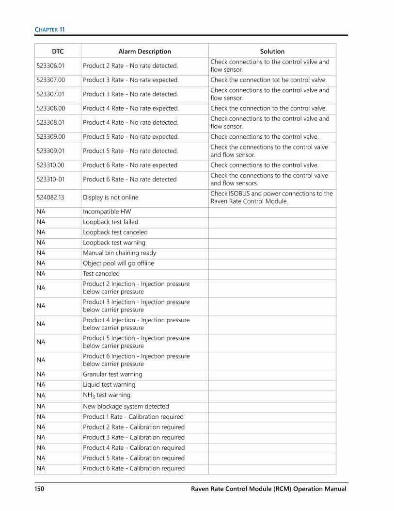
CHAPTER 11
523306.01 Product 2 Rate - No rate detected. Check connections to the control valve and flow sensor.
523307.00 Product 3 Rate - No rate expected. Check the connection tot he control valve.
523307.01 Product 3 Rate - No rate detected. Check connections to the control valve and flow sensor.
523308.00 Product 4 Rate - No rate expected. Check the connection to the control valve.
523308.01 Product 4 Rate - No rate detected. Check connections to the control valve and flow sensor.
523309.00 Product 5 Rate - No rate expected. Check connections to the control valve.
523309.01 Product 5 Rate - No rate detected. Check the connections to the control valve and flow sensor.
523310.00 Product 6 Rate - No rate expected Check connections to the control valve.
523310-01 Product 6 Rate - No rate detected Check the connections to the control valve and flow sensors.
524082.13 Display is not online Check ISOBUS and power connections to the Raven Rate Control Module.
NA Incompatible HWNA Loopback test failedNA Loopback test canceledNA Loopback test warningNA Manual bin chaining readyNA Object pool will go offlineNA Test canceled
NA Product 2 Injection - Injection pressure below carrier pressure
NA Product 3 Injection - Injection pressure below carrier pressure
NA Product 4 Injection - Injection pressure below carrier pressure
NA Product 5 Injection - Injection pressure below carrier pressure
NA Product 6 Injection - Injection pressure below carrier pressure
NA Granular test warningNA Liquid test warningNA NH3 test warningNA New blockage system detectedNA Product 1 Rate - Calibration requiredNA Product 2 Rate - Calibration requiredNA Product 3 Rate - Calibration requiredNA Product 4 Rate - Calibration requiredNA Product 5 Rate - Calibration requiredNA Product 6 Rate - Calibration required
DTC Alarm Description Solution
150 Raven Rate Control Module (RCM) Operation Manual

DIAGNOSTICS TROUBLE CODES
NA New switchbox detectedNA Product 1 Rate - Rate above targetNA Product 2 Rate - Rate above targetNA Product 3 Rate - Rate above targetNA Product 4 Rate - Rate above targetNA Product 5 Rate - Rate above targetNA Product 6 Rate - Rate above targetNA New direct injection pump detectedNA Product 1 - PWM duty maximum detectedNA Product 2 - PWM duty maximum detectedNA Product 3 - PWM duty maximum detectedNA Product 4 - PWM duty maximum detectedNA Product 5 - PWM duty maximum detectedNA Product 6 - PWM duty maximum detectedNA Product 1 Rate - Rate below targetNA Product 2 Rate - Rate below targetNA Product 3 Rate - Rate below targetNA Product 4 Rate - Rate below targetNA Product 5 Rate - Rate below targetNA Product 6 Rate - Rate below target
NA Product bin/tank 1 volume has fallen below the operator designated minimum level
NA Product bin/tank 2 volume has fallen below the operator designated minimum level
NA Product bin/tank 3 volume has fallen below the operator designated minimum level
NA Product bin/tank 4 volume has fallen below the operator designated minimum level
NA Product bin/tank 5 volume has fallen below the operator designated minimum level
NA Product bin/tank 6 volume has fallen below the operator designated minimum level
NA Product 1 Rate - Volume per minute below minimum
NA Product 1 - PWM duty cycle minimum reached.
NA Product 2 Rate - Volume per minute below minimum
NA Product 2 - PWM duty cycle minimum reached.
NA Product 3 Rate - Volume per minute below minimum
DTC Alarm Description Solution
016-0171-637 Rev. E 151

CHAPTER 11
NA Product 3 - PWM duty cycle minimum reached.
NA Product 4 Rate - Volume per minute below minimum
NA Product 4 - PWM duty cycle minimum reached.
NA Product 5 Rate - Volume per minute below minimum
NA Product 5 - PWM duty cycle minimum reached.
NA Product 6 Rate - Volume per minute below minimum
NA Product 6 - PWM duty cycle minimum reached.
NA Product bin/tank 1 level indicated empty bin/tank
NA Product bin/tank 2 level indicated empty bin/tank
NA Product bin/tank 3 level indicated empty bin/tank
NA Product bin/tank 4 level indicated empty bin/tank
NA Product bin/tank 5 level indicated empty bin/tank
NA Product bin/tank 6 level indicated empty bin/tank
NA Blockage system offline
NA Product 1 Rate - Application attempted with no controlled RPM speed.
NA Product 1 Rate - Application attempted with no monitored RPM speed.
NA Product 2 Rate - Application attempted with no controlled RPM speed.
NA Product 2 Rate - Application attempted with no monitored RPM speed.
NA Product 3 Rate - Application attempted with no controlled RPM speed.
NA Product 3 Rate - Application attempted with no monitored RPM speed.
NA Product 4 Rate - Application attempted with no controlled RPM speed.
NA Product 4 Rate - Application attempted with no monitored RPM speed.
NA Product 5 Rate - Application attempted with no controlled RPM speed.
DTC Alarm Description Solution
152 Raven Rate Control Module (RCM) Operation Manual

DIAGNOSTICS TROUBLE CODES
NA Product 5 Rate - Application attempted with no monitored RPM speed.
NA Product 6 Rate - Application attempted with no controlled RPM speed.
NA Product 6 Rate - Application attempted with no monitored RPM speed.
NA Communication lost with switchboxNA Scale 1 - Unexpected weight increaseNA Scale 2 - Unexpected weight increaseNA Scale 3 - Unexpected weight increaseNA Scale 4 - Unexpected weight increase
DTC Alarm Description Solution
016-0171-637 Rev. E 153

CHAPTER 11
154 Raven Rate Control Module (RCM) Operation Manual

APPENDIXA
016-0171-637 Rev. E
APPENDIX ACALIBRATION VALUES
SECTION WIDTHSUse the following formulas to help calculate the section widths.
Calculate the section width with the formula:
Where T = the number of Tips in each section, S = the Spacing between tips, and SW = the Section Width.
FOR EXAMPLE:20 tips in a section with spacing of 40 inches [50.8 cm] would yield:
or a Section Width of 800 inches [2032 cm] (approximately 67 feet [20 m]). Enter 800 [2032] as the width for this section.
TARGET RATE CALIBRATIONThe following information must be known in order to determine which spray nozzles to use with the sprayer:• Nominal Application Pressure_________ PSI [kpa]• Target Application Rate_________ GPA [lit/ha]• Target Speed_________ MPH [km/h]• Nozzle Spacing_________ inches [cm]
From this information, calculate the volume per minute per nozzle as follows:
NVPM = Nozzle Volume per Minute (gallons/acre [lit/ha]), Rate = target application Rate, Speed = target Speed of application, and NS = Nozzle Spacing
T S× SW=
20 40× 800=
NVPM Rate Speed× NS×5 940 60 000,[ ],
--------------------------------------------------=
155

APPENDIX A
FOR EXAMPLE:Application Pressure = 30 PSI, Target Application Rate = 20 GPA, Target Speed = 5.2 MPH, and Nozzle Spacing = 20 inches
Using the calculated nozzle volume per minute of 0.35 at an application pressure of 30, select a boom nozzle which comes closest to providing the desired output.
NVPM 20 5.2× 20×5 940,
-------------------------------- 0.35= =
156 Raven Rate Control Module (RCM) Operation Manual

APPENDIXB
016-0171-637 Rev. E
APPENDIX BREMOTE DIAGNOSTICS APPLICATION
This section provides information on the Remote Diagnostics Application (available on the Raven App store). RCM allows the user to control the system and perform diagnostics through a personal mobile device such as a tablet or smart phone. The user can turn on and off boom sections, turn the product on or off, and view real-time system information for troubleshooting or demonstration purposes without having to leave the cab. A Bluetooth low energy (BLE) compatible device is required.
The Remote Diagnostics Application is available for download and use on any Android or iOS Bluetooth low energy compatible device.
To use the diagnostics application:• System speed must be zero.• The application must be connected to RCM.• The Enable Wireless Control check box must be checked in the RCM User Settings.• Master Switch and Boom Section switches must be on.
NOTE: The Enable Wireless Control check box will automatically uncheck if a speed is detected.
DIAGNOSTIC MOBILE APP
BEST PRACTICES• Verify that the system speed is zero on the RCM home screen and there are no active system alarms.• Toggle all boom switches and the master switch to the ON position before connecting the mobile app.
CONNECT THE ECU1. With the machine on and parked, toggle all the section switches and the master switch to the on position.2. On the ISO UT, select the Settings menu and the Applicator Setup tab.
157

APPENDIX B
FIGURE 1. Enable Wireless
3. Select the Enable Wireless option at the bottom of the screen. The Wireless Connection Confirmation screen will display.
FIGURE 2. Enable Wireless
4. Power on the remote. When the light flashes red/green, enter the code displayed on the ISO UT and press the green button.
158 Raven Rate Control Module (RCM) Operation Manual

MOBILE APP SCREENSThe section provides an overview of the application screens.
DIAGNOSTICS
• Mobile Software - Application software version• ECU Software - Software version of the connected ECU• UT Status - UT Connection Status• ECU Voltage - voltage detected at the connected ECU• Pump PWM - PWM duty cycle• Signal Strength - Wireless signal strength at the time of connection• Packet Rate - Wireless data speed
Clears the passcodes entered into the mobile app. The passcode will need to be entered again next login.
016-0171-637 Rev. E 159

APPENDIX B
This list will show all of the supported RCM ECU Wireless IDs the mobile device has detected.
Select the desired ECU Wireless ID (the wireless ID can be found on the System Information screen on the RCM CT) and enter the passcode. The passcode will display on the UT screen. If the ECU Wireless ID has already been connected, no passcode is required and the application will automatically switch to the next page.
NOTE: Only one ECU can be connected at a time. The ECU wireless ID will not display if the RCM is connected to another mobile device.
NOTE: Selecting Demo Device will open the application in demo mode and will not connect to a ECU. This mode is for exploring the mobile application.
160 Raven Rate Control Module (RCM) Operation Manual
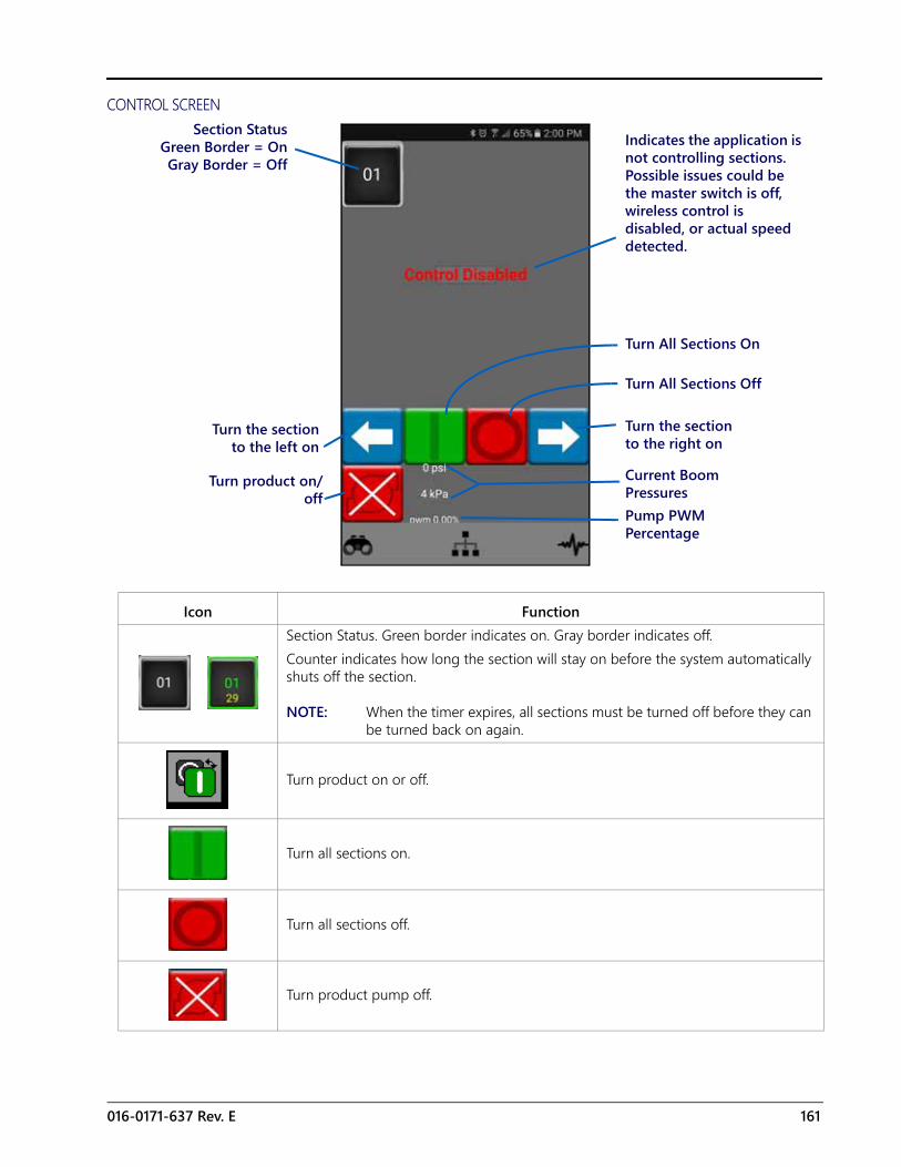
CONTROL SCREEN
Icon FunctionSection Status. Green border indicates on. Gray border indicates off.Counter indicates how long the section will stay on before the system automatically shuts off the section.
NOTE: When the timer expires, all sections must be turned off before they can be turned back on again.
Turn product on or off.
Turn all sections on.
Turn all sections off.
Turn product pump off.
Section StatusGreen Border = OnGray Border = Off
Indicates the application is not controlling sections. Possible issues could be the master switch is off, wireless control is disabled, or actual speed detected.
Turn the sectionto the left on
Turn product on/off
Pump PWM Percentage
Current Boom Pressures
Turn the section to the right on
Turn All Sections Off
Turn All Sections On
016-0171-637 Rev. E 161

APPENDIX B
162 Raven Rate Control Module (RCM) Operation Manual

APPENDIXC
016-0171-637 Rev. E
APPENDIX CSETTINGS AND HELP SCREEN TERMINOLOGY
TABLE 1. Setting and Help Screen Terminology
Setting Help Screen Terminology
Control DeadbandAllowable difference between the target and actual application rate. Rate correction is not performed as long as the application rate is within the allowable range.
Control Valve Type Select the type of control valve used to control the product application. Valve types include: Standard, Fast, Fast Close, PWM, and PWM Close.
Display SmoothingEnable the Display Smoothing feature to display target rate as actual rate when rate is within 10% of the target rate. Actual rate will be displayed if rate controller does not reach control deadband within ten seconds.
Enable Fence Rows Enable Fence Rows if sprayer is equipped. On-screen soft switches or physical switches can be assigned to control fence row valves. Restart the setup wizard to modify this setting.
Fill Flowmeter CalThe fill flowmeter calibration value and units may be found on the tag attached to the flowmeter installed in the tank fill system. Select the appropriate units for the flowmeter calibration to ensure proper calibration of the tank fill system.
Flowmeter CalThe flowmeter calibration value and units may be found on the tag attached to the flowmeter installed in the application system. Select the appropriate units for the flowmeter calibration to ensure proper calibration of the application system.
Implement Switch The implement switch senses the position of the toolbar and turns off application when raised and enables application when lowered.
Low Tank LimitEnable the Low Tank feature and enter desired volume threshold at which an alert will be displayed for low tank condition. Tank volume must be either manually set upon refilling or tank fill flowmeter utilized to automatically monitor tank level.
Max Pump PWMEnter a maximum PWM duty cycle percent to set the maximum desired output for a pulse width modulated (PWM) hydraulic control valve. This setting limits how far the PWM valve will open.
Maximum PressureEnter the maximum desired pressure for the system. Upon exceeding maximum pressure, an alert will be displayed, flow control will be overridden and the rate controller will maintain maximum pressure.
Min Pump PWMEnter a minimum PWM duty cycle percent to set the minimum desired output (zero point or shutoff point) for a pulse width modulated (PWM) hydraulic control valve).
Minimum PressureThe minimum pressure feature will allow the operator to set the lowest tolerable pressure during field operations. If the application system reaches the minimum pressure, the UT will display an alert and application system will maintain the flow rate to keep the monitored pressure consistent and to maintain the spray pattern.
Number of Sections The number of sections is the number of section valves installed on the machine.
163

APPENDIX C
Pressure Transducer Type
Select the pressure sensor range from the drop down Menu. Refer to OEM for transducer installed, or Raven part numbers.
Pressure Sensor Type Select the pressure sensor drop down field and select the transducer to be calibrated for operation.
PWM StandbyEnter desired control valve PWM duty cycle percent when all sections are off. This is utilized when standby pressure control is not available (pressure sensor not available or direct injection is installed).
Rate Presets Enter desired rate presets to allow the operator to quickly switch between target rates during field operation in the automatic rate control mode.
Response RateThe response rate has a range of 1 to 100 and the setting determines how aggressively the target is controlled to. Increasing this value will cause the system to respond more quickly. Decreasing it will cause a slower response. If the system is slow to reach the target value consider increasing it.
Speed CalEnter the Speed Cal value of radar speed sensor (if equipped). Reference radar manufacturer's specification for recommended value and perform distance calibration to ensure accuracy.
Tank Capacity Enter maximum capacity of the tank.Tank Volume Enter the current tank level.
Setting Help Screen Terminology
164 Raven Rate Control Module (RCM) Operation Manual
016-0171-537 Rev. H, E29761
We
Solv
e Gr
eat C
halle
nges
.
LIMITED WARRANTY WHAT DOES THIS WARRANTY COVER? This warranty covers all defects in workmanship or materials in your Raven Applied Technology Division product under normal use, maintenance, and service when used for intended purpose.
HOW LONG IS THE COVERAGE PERIOD? Raven Applied Technology products are covered by this warranty for 12 months from the date of retail sale. In no case will the Limited Warranty period exceed 24 months from the date the product was issued by Raven Industries Applied Technology Division. This warranty coverage applies only to the original owner and is non-transferable.
HOW CAN I GET SERVICE? Bring the defective part and proof of purchase to your Raven dealer. If the dealer approves the warranty claim, the dealer will process the claim and send it to Raven Industries for final approval. The freight cost to Raven Industries will be the customer’s responsibility. The Return Materials Authorization (RMA) number must appear on the box and all documentation (including proof of purchase) must be included inside the box to be sent to Raven Industries.
WHAT WILL RAVEN INDUSTRIES DO? Upon confirmation of the warranty claim, Raven Industries will (at our discretion) repair or replace the defective product and pay for the standard return freight, regardless of the inbound shipping method. Expedited freight is available at the customer’s expense.
WHAT IS NOT COVERED BY THIS WARRANTY? Raven Industries will not assume any expense or liability for repairs made outside our facilities without written consent. Raven Industries is not responsible for damage to any associated equipment or products and will not be liable for loss of profit, labor, or other damages. The obligation of this warranty is in lieu of all other warranties, expressed or implied, and no person or organization is authorized to assume any liability for Raven Industries.
Damages caused by normal wear and tear, misuse, abuse, neglect, accident, or improper installation and maintenance are not covered by this warranty.

016-0171-536 Rev. B, E29761
We
Solv
e Gr
eat C
halle
nges
.
EXTENDED WARRANTY WHAT DOES THIS WARRANTY COVER? This warranty covers all defects in workmanship or materials in your Raven Applied Technology Division product under normal use, maintenance, and service when used for intended purpose.
DO I NEED TO REGISTER MY PRODUCT TO QUALIFY FOR THE EXTENDED WARRANTY? Yes. Products/systems must be registered within 30 days of retail sale to receive coverage under the Extended Warranty. If the component does not have a serial tag, the kit it came in must be registered instead.
WHERE CAN I REGISTER MY PRODUCT FOR THE EXTENDED WARRANTY? To register, go online to www.ravenhelp.com and select Product Registration.
HOW LONG IS THE EXTENDED WARRANTY COVERAGE PERIOD? Raven Applied Technology products that have been registered online are covered for an additional 12 months beyond the Limited Warranty for a total coverage period of 24 months from the date of retail sale. In no case will the Extended Warranty period exceed 36 months from the date the product was issued by Raven Industries Applied Technology division. This Extended Warranty coverage applies only to the original owner and is non-transferable.
HOW CAN I GET SERVICE? Bring the defective part and proof of purchase to your Raven dealer. If the dealer approves the warranty claim, the dealer will process the claim and send it to Raven Industries for final approval. The freight cost to Raven Industries will be the customer’s responsibility. The Return Materials Authorization (RMA) number must appear on the box and all documentation (including proof of purchase) must be included inside the box to be sent to Raven Industries. In addition, the words “Extended Warranty” must appear on the box and all documentation if the failure is between 12 and 24 months from the retail sale.
WHAT WILL RAVEN INDUSTRIES DO? Upon confirmation of the product’s registration for the Extended Warranty and the claim itself, Raven Industries will (at our discretion) repair or replace the defective product and pay for the standard return freight, regardless of the inbound shipping method. Expedited freight is available at the customer’s expense.
WHAT IS NOT COVERED BY THE EXTENDED WARRANTY? Raven Industries will not assume any expense or liability for repairs made outside our facilities without written consent. Raven Industries is not responsible for damage to any associated equipment or products and will not be liable for loss of profit, labor, or other damages. Cables, hoses, software enhancements, and remanufactured items are not covered by this Extended Warranty. The obligation of this warranty is in lieu of all other warranties, expressed or implied, and no person or organization is authorized to assume any liability for Raven Industries.
Damages caused by normal wear and tear, misuse, abuse, neglect, accident, or improper installation and maintenance are not covered by this warranty.