rdbe overview - nasa · 2018-11-21 · •rdbe – roach digital backend system – joint...
TRANSCRIPT

RDBE Overview
Chet RuszczykIVS 6th TOW 2011
16th IVS TOW May 2011

Agenda
• System overview– Hardware components– Firmware components– Software components
• Features• Command set• Basic operation• Demonstration
6th IVS TOW May 2011 2

System Overview
• RDBE – ROACH Digital Backend System– Joint collaboration between NRAO and Haystack– Name is assigned to a specific base system
• Specific hardware components• Can be ordered from Digicom
– Variations are expected• Represented by hyphenating the name• e.g. RDBE-H, RDBE-S• This overview covers the RDBE-H
6th IVS TOW May 2011 3

RDBE-H Block Diagram
6th IVS TOW May 2011 4
CX4/4x
Z-DOK
Z-DOK
10GigEEthernetData Out
ROACH
CX4/4x
CX4/4x
CX4/4x
10/100/1000T
PPC 440 EPxComputer
ALC
LVDS GPIO + CLK
USB2
RS232
iADC8 bit
Sampler
120 VacPower supplies
Ethernet Control100 Mbit
TTL GPIO
V5SX95TPFBor
DDCSynthBoard
1 PPS
5 MHz
1024 MHz
IF0
1 PPS
IF1
SMA Connector
DOT Mon Diode Ctl

RDBE Hardware Components
• ROACH Board– Reconfigurable Open
Architecture Computing Hardware
– Developed by the CASPER group at Berkeley / NRAO / KAT
• Virtex 5 FPGA• 440 PPC processor• 2G RAM• 2 ZDOK connectors
– iADC• RS232 interface• 1G / 100M ethernet• 4 CX4 10G ethernet ports• 1 XPORT interface
6th IVS TOW May 2011 5

RDBE Hardware Components
• iADC– Analog to Digital
Converter (sampler board)• Developed by the CASPER
group
– 2GHz bandwidth– 1 Gigs sample / sec– 8 bits / sample
6th IVS TOW May 2011 6

RDBE Hardware Components
• Synthesizer / timing board– Developed NRAO– Inputs
• 5MHz• 1pps
– Outputs• 1pps • 1024 MHz
– Provides serial communication interface to ALC board
6th IVS TOW May 2011 7

RDBE Hardware Components
• ALC– Analog level control– Developed by NRAO– 2 IFs in / 2IFs out– 0-31 dB attenuator– Additional 20dB solar
attenuator
6th IVS TOW May 2011 8

RDBE Hardware Components
• Miscellaneous– Power supply
• 90 ~ 132 VAC or 180 ~ 264 VAC auto sensing
– 1pps LED• Indicates 1pps to
synthesizer board
– 10 SMA connectors
6th IVS TOW May 2011 9
RDBE-H Back Panel

RDBE Firmware• 3 Personality types (FPGA code)
– Polyphase filter bank-geodesy (pfbg)• Input is two 512MHz IFs • Output is sixteen of 32 possible 32-MHz channels• Output is a 5008 byte Mark5B data format (next slide)
– Polyphase filter bank-astronomy (pfba)• Input is four 512 MHz IFs • Output uses two of the four 10Gbps CX4 interfaces
– 2-bit quantized – 4Gbps / interface– 8224 byte packets using the VDIF format.
– Digital down converter (ddc)• Input is two 512MHz IFs • Output is eight tunable channels • Bandwidths ranges down in binary steps from 128 MHz to 62.5kHz• Output is in 5008 byte Mark5B format 2 bits / sample
6th IVS TOW May 2011 10

Mark5B Payload
6th IVS TOW May 2011 11
1248 32 bit words
Mark5B Header (4 words)
32 bit PSNZero Byte fill
1252 32 bit words
32 bit PSNZero Byte fill
Mark5B Header (4 words)
2500 32 bit words
Original Mark5B packetRDBE Mark5B Equivalent

RDBE Software
6th IVS TOW May 2011 12

RDBE Software• rdbe_dev.ko
– Linux kernel device driver– Allows the application to read / write to the FPGA
personality• HAL
– Hardware abstraction layer– Allows the personality to change without changing the
application software• rdbe_server
– Accepts VSI-S commands– Verifies and takes actions on valid commands– Specified in the RDBE Command Set
6th IVS TOW May 2011 13

RDBE Command Set• Standard VSI-S command format• http://www.haystack.edu/tech/vlbi/mark5/mark5_memos/091.pdf
dbe_1pps_mon Set the 1pps monitoring broadcast statedbe_alc Set / get the ALC attenuator setting for INPUT 0/1dbe_alc_pps? Station 1pps status (query only)dbe_alc_fpgavers Get the ALC boards FPGA bit code version (query only) dbe_arp Set / get the IP to MAC address resolutiondbe_data_connect Set / get the destination IP the data is being sentdbe_data_format Set the packet format mode to either the VDIF native mode or Mark5B compatibility modedbe_data_send Transmit a data stream out of the DBE 10G interfacedbe_dc_cfg Setup down-convertersdbe_dot? Get the Data Observable Time (DOT) clock information (query only)dbe_dot_inc Increment the DOT clockdbe_dot_set Set the DOT clock on next 1pps ticdbe_execute Execute specific command on the DBEdbe_hw_version? Get the hardware version information from the DBEdbe_ifconfig Set / get DBE 10G network interface configurationdbe_ioch_assign Set / get the input to output channel assignmentsdbe_packet Set / get packet transmission criteriadbe_personality Set / get the RDBE FPGA bit code personalitydbe_quantize Set / get present channel quantization datadbe_status? Get system status (query only)dbe_sw_version? Get the software version information from the DBEdbe_tsys_mon Set the Tsys monitoring broadcast statedbe_xbar Set/get the DDC crossbar switch positions
6th IVS TOW May 2011 14

Basic Operations
• Topics addressed on the following slides– Boot Up– rdbe_server daemon communication
• dbe_data_send operational modes• raw capture mode• monitoring capabilities
– 1pps – tsys
– Software utilities
6th IVS TOW May 2011 15

Boot Up
• U-Boot options– Environment variables defining what the
boot loader will execute• location of the kernel in flash (address)• location of the root file system
– USB– NFS– SDRAM– bootp
• Network configuration– Static – Dynamic
– Details are beyond the scope of this talk• Detail documentation available if needed
6th IVS TOW May 2011 16

rdbe_server• Loading the FPGA personality
– Located where the root file system is mounted
– /home/roach/personalities• Initialization
– Setting the FPGA registers– Setting the DOT time
• system time• manually
– Quantization • Formats the filter bank channels at 2
bits / sample– Monitoring capabilities
• Set for normal operations– Transmitting data out CX4 interface– Status / etc.
6th IVS TOW May 2011 17

IO Channel Assignment• Capability to set the input output channel assignment
for the VLBI Payload– Feature for PFBG personality only
• Input is two 512MHz IFs • Output is sixteen of 32 possible 32-MHz channels
– The command • dbe_ioch_assign = <input>:<channel(s)>: [<threadID>] : …
[<input>]:[<channel(s)>]: [<threadID>] ;– input
• 0 or 1 for IF0 or IF1– channel(s)
• Either individual channels or a range of channels– threadID
• vdif specific and presently ignored
6th IVS TOW May 2011 18
IO Channel Assignment
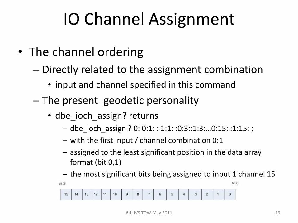
• The channel ordering – Directly related to the assignment combination
• input and channel specified in this command
– The present geodetic personality• dbe_ioch_assign? returns
– dbe_ioch_assign ? 0: 0:1: : 1:1: :0:3::1:3:…0:15: :1:15: ; – with the first input / channel combination 0:1 – assigned to the least significant position in the data array
format (bit 0,1) – the most significant bits being assigned to input 1 channel 15
6th IVS TOW May 2011 19

IO Channel Assignment
• A common setting used for testing with DBBC– dbe_ioch_assign = 0: 0-15 ; – Assigns all of IF0s 32 MHz channels to the VLBI
Payload– dbe_ioch_assign? returns
• dbe_ioch_assign ? 0: 0:1: : 0:2: :0:3::0:4:…0:14: :0:15: ; – with the first input / channel combination 0:1 – assigned to the least significant position in the data array
format (bit 0,1) – the most significant bits being assigned to input 0 channel 15
6th IVS TOW May 2011 20

Data Transmission
• In the past data were always available and the gating function was performed on the recording device– Record = on / off commands
• A new approach has been taken for when to transmit data out of the interface– Since the start and end time are known apriori
• use the dbe_data_send to gate the output on the 10G• past option is still available
6th IVS TOW May 2011 21

Design Philosophy
• start time <= present DOT time < end time– Personality will transmit valid packets– Times are specified as integer seconds
• Start and end times are programmed into the FPGA using the command:– dbe_data_send– command format
• dbe_data_send = < state > : [< ts >] : [<te>] : [<delta>];– state - either “on” or “off”– start and end times (ts, te) are of the format YYYYDDDHHMMSS– delta - specified in integer seconds.
6th IVS TOW May 2011 22

dbe_data_send options• Specify start / end time
– YYYYDDDHHMMSS• Or specify start and delta time
– t2 is generated as t1 + delta– delta is integer seconds
• Ability to abort an active transmission– send the off state with
• a specified time• no time - meaning next integer
second
6th IVS TOW May 2011 23
dbe_data_send = on: t1: t2;
time time
t1
t2
RDBE Mark5CCommand& Control
time
dbe_data_send = on: t1: t2;
time time
t1
t2
RDBE Mark5CCommand& Control
time
dbe_data_send = off: : tA;
tA

Raw Capture Mode
• Provides ability to see the incoming signal from the iADC before it is processed by the FPGA personality
• It is a separate thread within the rdbe_server– Listening on port 5000– Responds to a client requesting a specific IF to capture
• 32000 samples are captured• the raw data are returned to the calling client to be
processed– by software utility “bpplotter”
» developed by NRAO
6th IVS TOW May 2011 24

bpplotter
6th IVS TOW May 2011 25

bpplotter
6th IVS TOW May 2011 26

bpplotter
6th IVS TOW May 2011 27

Monitoring Capabilities
• 1pps monitoring – dbe_1pps_mon = <enable> : <multicast IP address>;
• Tsys monitoring (version 1.4 of fpga code)– System temperature measurement– On power / off power of the receive chain– dbe_tsys_mon = <enable> : <multicast IP address> :
[<port>] : [<interval>];
6th IVS TOW May 2011 28

Software Uilities
• rbde_client -h <machine>– Command line interface to RDBE– -h <machine> is the target RDBE systems IP
address (defaults to localhost). – rdbe_server must be running on <machine>
• rdbe_gui– Graphical client interface to the RDBE
6th IVS TOW May 2011 29

Software Uilities• gDot -h <multicast address>
– A graphical multicast 1pps time receiver• that displays the broadcast DOT time
– The RDBE server must be configured • with the dbe_1pps_mon command.
• power_est_client -h <machine> – A command line client
• calculates the mean, standard deviation and maximum power of a specified input IF into the RDBE.
• the input IF is selected by sending a 0 or 1 at the command prompt.
6th IVS TOW May 2011 30

DEMONSTATION
6th IVS TOW May 2011 31