re: old saratoga hospital structural evaluation providence
TRANSCRIPT

RYAN BIGGS │CLARK DAVIS CAPITAL DISTRICT-CORPORATE OFFICE FINGER LAKES OFFICE HUDSON VALLEY OFFICE ENGINEERING & SURVEYING 257 Ushers Road 4592 Jordan Road, PO Box 217 20 Shaker Road, PO Box 730 www.ryanbiggs.com Clifton Park, NY 12065 Skaneateles Falls, NY 13153 New Lebanon, NY 12125 [email protected] p 518 406.5506 p 315 685.4732 p 518 794.8613
April 19, 2016 Mr. Blake MacKinney Response Manager Environmental Restoration LLC 1666 Fabick Drive Fenton, MO 63026 Re: Old Saratoga Hospital Structural Evaluation Providence, New York Ryan Biggs | Clark Davis Project 11373 ER Purchase Order # 11490 Dear Blake: At your request, I made site observations of the building at 7239 Barkersville Road in Providence, NY on April 7, 2016. The property is a vacant two-story health care facility. Environmental Restoration LLC is currently conducting asbestos abatement work on the basement level. The purpose of the observation was to provide a visual condition assessment of the condition of the existing structure on the upper floors and roof framing for the purpose of allowing abatement work to progress to other areas of the structure. Description The building has two above-grade floors with a basement level and small rooftop structure located in the center of the main hospital construction. An aerial photograph of the structure is shown in Photograph 1. Each floor comprises approximately 15,500 square feet. The rooftop structure is approximately 2,800 square feet and is only accessible through exterior access on the roof. At least two additions were constructed onto the original hospital at the eastern end of the structure. Exterior architectural features indicate that the eastern wing addition was the children’s wing of the hospital. (Photograph 1) The keystone located at the main entrance of the hospital indicates a date of 1937. The first and second-floor construction consists of a conventionally reinforced cast-in-place concrete waffle slab supported by steel beams and columns at the interior of the building. The exterior walls of the structure are load bearing brick masonry. The roof construction varies somewhat depending on location, but generally consists of steel bar joists spanning from the north and south exterior brick walls to steel beams running the building long direction. The joists support the structural roof deck. In some areas the roof deck is a thin cast-in-place concrete slab cast on a steel reinforcing mesh while in others the deck consists of thin concrete panels supported on steel bulb-tees or angles, which span to the roof joists.

RYAN BIGGS │CLARK DAVIS Ryan Biggs | Clark Davis Project 11373 ENGINEERING & SURVEYING Page 2 www.ryanbiggs.com
Photograph 1 – Old Saratoga Hospital Aerial View We understand interior demolitions for attempted redevelopment in the mid 1980s have removed many of the interior concrete-masonry partitions and finishes in the main hospital structure. Interior masonry partitions in the east children’s wing have been demolished, but debris has not been removed and is piled on the floors, making foot travel difficult. The building has been the object of extensive vandalism. The exterior windows are broken, graffiti is present in many of the rooms, and copper piping and roof-top parapet flashing have been destructively removed. These vandalism activities have opened up the building interior to weather and contributed greatly to the deterioration of the interior finishes and structural system. (Photograph 2)
Photograph 2 – Main (Central) Hospital Entrance
East Wing Addition

RYAN BIGGS │CLARK DAVIS Ryan Biggs | Clark Davis Project 11373 ENGINEERING & SURVEYING Page 3 www.ryanbiggs.com
The structural observations were conducted for the purpose of identifying obvious areas of structural framing which are deteriorated or have been damaged such that they no longer provide safe capacity for occupancy during the asbestos abatement process. Due to the asbestos materials present in the structure, and in accordance with Ryan Biggs | Clark Davis’ proposal for engineering services, the structural observations were limited to visual observations and included no removal of interior finishes and no disturbance of debris. Limited observation of the basement level was conducted in the eastern children’s wing and no observation of the basement level in the remainder of the structure was conducted due to ongoing asbestos abatement activities. No structural analysis was performed to identify existing framing load capacities. Observations and Recommendations This report provides the location and description of areas of framing deemed unsafe to support temporary occupancy loading during asbestos abatement procedures. General building safety hazards due to broken windows, deteriorated wall and ceiling finishes, and failing architectural elements exist throughout the structure are only described for typical conditions within the report. Therefore, these items are not specifically indicated on building area Figures 1 through 6. These hazards must be identified and addressed by the owner and abatement team on a room by room basis. The structure is not habitable or safe for occupancy by the general public. GENERAL BUILDING SAFETY HAZARDS:
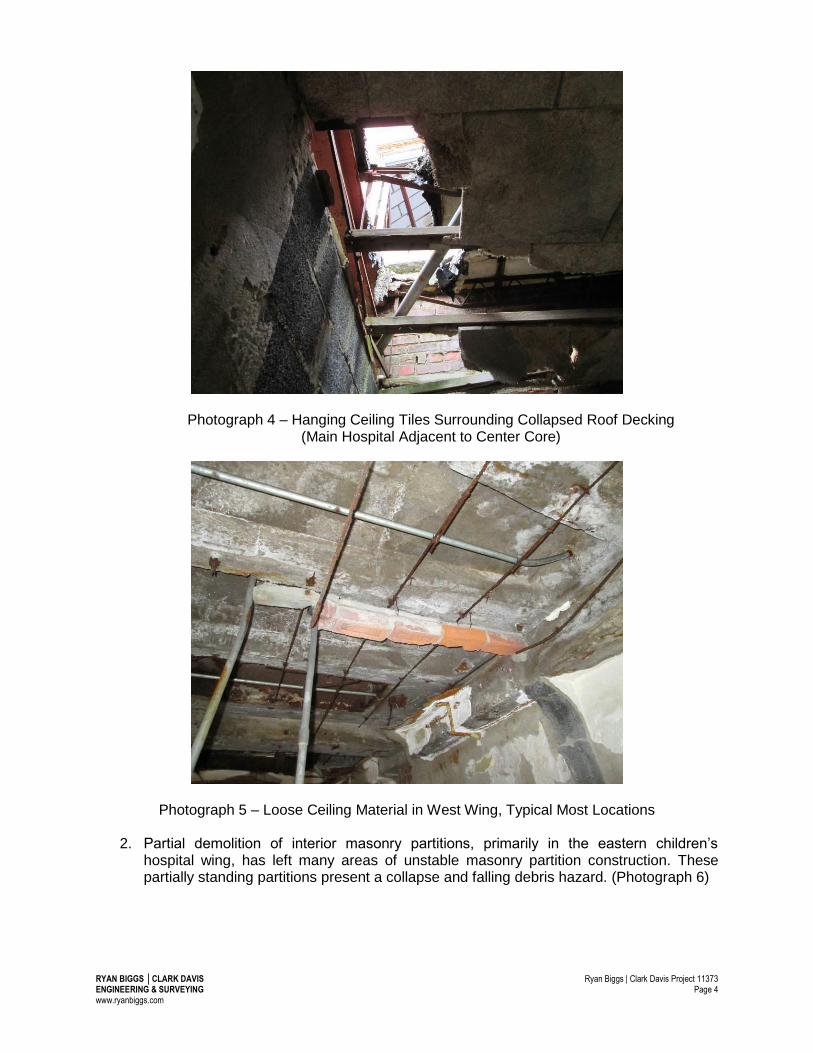
1. Water penetration into the structure has caused irreparable damage to the plaster ceilings in all areas of the structure observed. Where the ceiling has not completely collapsed, danger from deteriorated and compromised plaster and masonry ceiling finishes constitute a falling debris hazard. (Photographs 3, 4, and 5)
Photograph 3 – Deteriorated Ceiling Construction along Main Hospital Corridor
RYAN BIGGS │CLARK DAVIS Ryan Biggs | Clark Davis Project 11373 ENGINEERING & SURVEYING Page 4 www.ryanbiggs.com
Photograph 4 – Hanging Ceiling Tiles Surrounding Collapsed Roof Decking (Main Hospital Adjacent to Center Core)
Photograph 5 – Loose Ceiling Material in West Wing, Typical Most Locations
2. Partial demolition of interior masonry partitions, primarily in the eastern children’s hospital wing, has left many areas of unstable masonry partition construction. These partially standing partitions present a collapse and falling debris hazard. (Photograph 6)

RYAN BIGGS │CLARK DAVIS Ryan Biggs | Clark Davis Project 11373 ENGINEERING & SURVEYING Page 5 www.ryanbiggs.com
Photograph 6 – Partially Demolished Interior Masonry Partition
3. Previous redevelopment/renovation activities, which were terminated, have left piles of masonry partition debris in many areas. If abatement activities are required where debris piles are present, the debris should be removed prior to occupancy to reduce the possibility of local overloading of the floor structure from the additional occupancy loading. (Photographs 7 and 8)
Photograph 7 – Demolition Debris on 1st Floor in Children’s Wing

RYAN BIGGS │CLARK DAVIS Ryan Biggs | Clark Davis Project 11373 ENGINEERING & SURVEYING Page 6 www.ryanbiggs.com
Photograph 8 – Demolition Debris on 1st Floor in Main Hospital Patient Room
4. Partial collapse of clay masonry wall finishes has occurred in many areas. The remaining clay masonry elements are unstable and constitute a falling debris hazard if disturbed. (Photograph 9.)

RYAN BIGGS │CLARK DAVIS Ryan Biggs | Clark Davis Project 11373 ENGINEERING & SURVEYING Page 7 www.ryanbiggs.com
Photograph 9 – Unstable Interior Clay Masonry Finish in Main Hospital Patient Rooms
5. Access onto the roof should be limited to only those areas specifically indicated in this report. Intact hung ceiling construction over the majority of the top floor greatly restricted visual observation of the roof framing. Framing was only exposed in areas where the roof deck material had already collapsed, and along some of the exterior walls and interior support points of the steel roof joists. Those areas where observations yielded steel roof joists in a compromised state have been indicated elsewhere in this report.
6. Vandalism and subsequent water damage have deteriorated and compromised the perimeter brick masonry roof parapets around the majority of the structure. Access to the exterior of the structure within approximately 10 feet of the perimeter walls should be limited to avoid falling brick and other debris.
RYAN BIGGS │CLARK DAVIS Ryan Biggs | Clark Davis Project 11373 ENGINEERING & SURVEYING Page 8 www.ryanbiggs.com
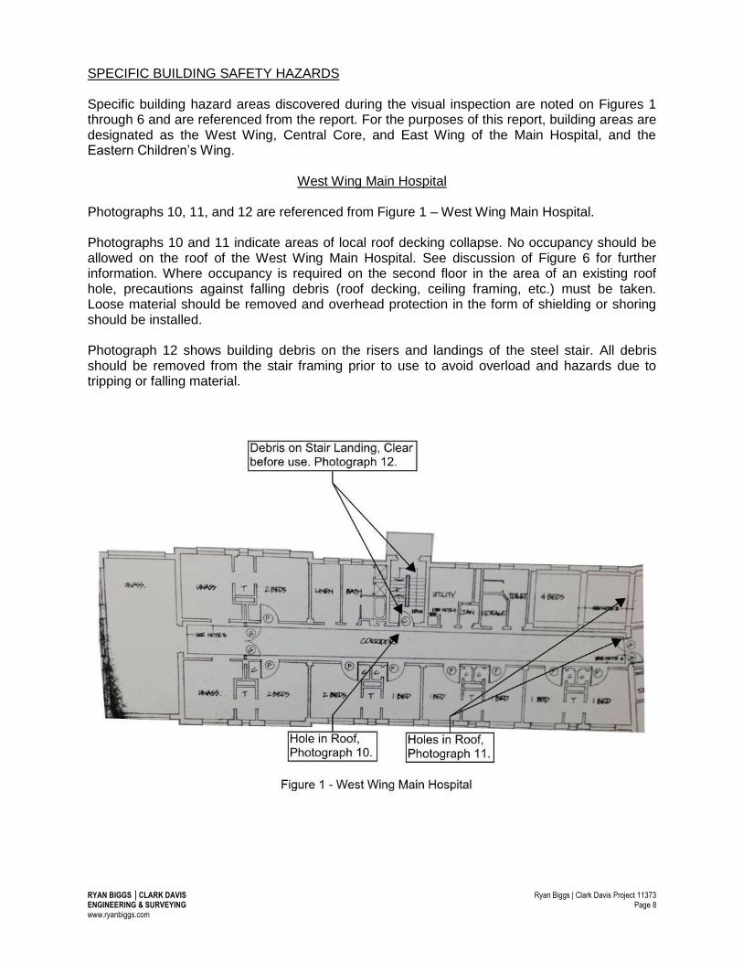
SPECIFIC BUILDING SAFETY HAZARDS Specific building hazard areas discovered during the visual inspection are noted on Figures 1 through 6 and are referenced from the report. For the purposes of this report, building areas are designated as the West Wing, Central Core, and East Wing of the Main Hospital, and the Eastern Children’s Wing.
West Wing Main Hospital Photographs 10, 11, and 12 are referenced from Figure 1 – West Wing Main Hospital. Photographs 10 and 11 indicate areas of local roof decking collapse. No occupancy should be allowed on the roof of the West Wing Main Hospital. See discussion of Figure 6 for further information. Where occupancy is required on the second floor in the area of an existing roof hole, precautions against falling debris (roof decking, ceiling framing, etc.) must be taken. Loose material should be removed and overhead protection in the form of shielding or shoring should be installed. Photograph 12 shows building debris on the risers and landings of the steel stair. All debris should be removed from the stair framing prior to use to avoid overload and hazards due to tripping or falling material.

RYAN BIGGS │CLARK DAVIS Ryan Biggs | Clark Davis Project 11373 ENGINEERING & SURVEYING Page 9 www.ryanbiggs.com
Photograph 10 – Hole in Roof Framing by West Wing Stair
Photograph 11 – Holes in Roof of West Wing Framing Adjacent to Central Roof Top Structure

RYAN BIGGS │CLARK DAVIS Ryan Biggs | Clark Davis Project 11373 ENGINEERING & SURVEYING Page 10 www.ryanbiggs.com
Photograph 12 – Debris on West Wing Stair

RYAN BIGGS │CLARK DAVIS Ryan Biggs | Clark Davis Project 11373 ENGINEERING & SURVEYING Page 11 www.ryanbiggs.com
Central Core Main Hospital Photographs 13, 15 and 16 are referenced from Figure 2 – Central Core Main Hospital – First Floor. Photographs 14 and 17 are referenced from Figure 3 – Central Core Main Hospital – Second Floor.
Steel stairs in the central building area are not in a safe or usable condition. Photographs 13 and 14 show heavy debris collapse at the main grand staircase, which prohibited visual observation of the condition of the steel and does not allow for safe pedestrian access. Clearing of building debris to allow structural evaluation of the integrity of this stair by a registered professional engineer is required prior to use.

RYAN BIGGS │CLARK DAVIS Ryan Biggs | Clark Davis Project 11373 ENGINEERING & SURVEYING Page 12 www.ryanbiggs.com
Photograph 15 shows collapse of the stair framing in the northmost back-stage area caused by extensive rust and deterioration of the steel treads and connection clips. Replacement of the deteriorated and failed steel framing and evaluation of the other existing treads of this stair is the minimum required remedial measure to allow use. Design of remedial framing for this stair should be provided by a registered professional engineer.

RYAN BIGGS │CLARK DAVIS Ryan Biggs | Clark Davis Project 11373 ENGINEERING & SURVEYING Page 13 www.ryanbiggs.com
Significant demolition debris is present in the central core area as shown in Photograph 16. If asbestos abatement activities are required within the vicinity of present debris, (approximately 10 foot radius outside of debris area), the debris should be removed prior to conducting abatement work to avoid overload of the floor framing. The wood stage framing on the second floor of the Central Core is not safe to support loading. (Photograph 17) Temporary shoring and support of this wood platform framing should be installed to the concrete floor below if access is required.
Photograph 13 – Debris on First Floor of Central Grand Staircase
Photograph 14 – Debris on Second Floor of Central Grand Staircase

RYAN BIGGS │CLARK DAVIS Ryan Biggs | Clark Davis Project 11373 ENGINEERING & SURVEYING Page 14 www.ryanbiggs.com
Photograph 15 – Failed Stair Treads and Risers at Back-Stage Stair
Photograph 16 – Demolition Debris in Central Core Floor Area

RYAN BIGGS │CLARK DAVIS Ryan Biggs | Clark Davis Project 11373 ENGINEERING & SURVEYING Page 15 www.ryanbiggs.com
Photograph 17 – Failed Wood Stage Platform Framing
East Wing Main Hospital Photographs 18 to 27 are referenced from Figure 4 – East Wing Main Hospital.

RYAN BIGGS │CLARK DAVIS Ryan Biggs | Clark Davis Project 11373 ENGINEERING & SURVEYING Page 16 www.ryanbiggs.com
Significant demolition debris is present in the East Wing area as shown in Photographs 18 and 19. If asbestos abatement activities are required within the vicinity of present debris, (approximately 10 foot radius outside of debris area), the debris should be removed prior to conducting abatement work to avoid overload of the floor framing.
Photograph 18 – Demolition Debris in East Wing – First Floor
Photograph 19 – Demolition Debris in East Wing – First Floor
RYAN BIGGS │CLARK DAVIS Ryan Biggs | Clark Davis Project 11373 ENGINEERING & SURVEYING Page 17 www.ryanbiggs.com
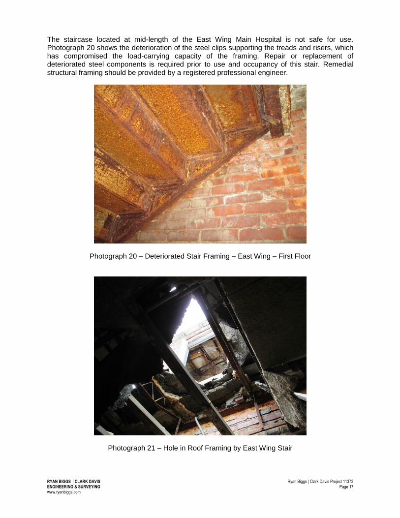
The staircase located at mid-length of the East Wing Main Hospital is not safe for use. Photograph 20 shows the deterioration of the steel clips supporting the treads and risers, which has compromised the load-carrying capacity of the framing. Repair or replacement of deteriorated steel components is required prior to use and occupancy of this stair. Remedial structural framing should be provided by a registered professional engineer.
Photograph 20 – Deteriorated Stair Framing – East Wing – First Floor
Photograph 21 – Hole in Roof Framing by East Wing Stair

RYAN BIGGS │CLARK DAVIS Ryan Biggs | Clark Davis Project 11373 ENGINEERING & SURVEYING Page 18 www.ryanbiggs.com
Photographs 21 and 22 indicate areas of local roof decking collapse. No occupancy should be allowed on the roof in the East Wing Main Hospital. Where occupancy is required on the second floor in the area of an existing roof hole, precautions against falling debris (roof decking, ceiling framing, etc.) must be taken. Loose material should be removed and overhead protection in the form of shielding or shoring should be installed.
Photograph 22 – Hole in Roof – East Wing Main Hospital
Photograph 23 – Brick Supported on Failing Steel Door Frame – East Wing – First Floor

RYAN BIGGS │CLARK DAVIS Ryan Biggs | Clark Davis Project 11373 ENGINEERING & SURVEYING Page 19 www.ryanbiggs.com
Photograph 23 indicates brick supported by a failing door frame. The falling debris hazard is limited to the row of brick immediately above the steel door frame as the remaining brick above is supported by a steel angle lintel, which appears to still be in serviceable condition.
Photograph 24 – Unsafe Concrete Joist Framing – Second Floor
Photograph 25 – Hole in Roof Framing

RYAN BIGGS │CLARK DAVIS Ryan Biggs | Clark Davis Project 11373 ENGINEERING & SURVEYING Page 20 www.ryanbiggs.com
Local collapse of the roof structure and subsequent deterioration of the second-floor concrete joist framing have created an unsafe condition in the room area indicated by Photographs 24, 25, and 26. Occupancy on either the first or second floor in these areas is not safe. Shoring of the floor framing to grade at the basement level should be conducted if abatement activities are required in this area. Design of safety shoring should be conducted by a registered professional engineer.
Photograph 26 – Debris Below Roof Framing Collapse and Above Deteriorated Joist Framing
Photograph 27 – Damaged Concrete Joist Framing – East Wing – Second Floor

RYAN BIGGS │CLARK DAVIS Ryan Biggs | Clark Davis Project 11373 ENGINEERING & SURVEYING Page 21 www.ryanbiggs.com
Second-floor framing indicated in the area of Photograph 27 has been compromised due to rusting and corrosion of the steel reinforcing which has caused cracking and deterioration of the concrete joists. The framing is not safe for occupancy during asbestos abatement operations. If occupancy of this area on the second floor is required, reshoring of the floor to the first-floor framing and to grade is required. Design of safety shoring should be conducted by a registered professional engineer.
Eastern Children’s Wing Photographs 6, 28, 29, and 30 are referenced from Figure 5 – Eastern Children’s Wing.
Significant demolition debris is present in the Eastern Children’s Wing area as shown in Photograph 6. If asbestos abatement activities are required within the vicinity of present debris, (approximately 10 foot radius outside of debris area), the debris should be removed prior to conducting abatement work to avoid overload of the floor framing. Photograph 28 indicates an area of local roof decking deterioration. No occupancy should be allowed on the roof of the Eastern Children’s Wing.

RYAN BIGGS │CLARK DAVIS Ryan Biggs | Clark Davis Project 11373 ENGINEERING & SURVEYING Page 22 www.ryanbiggs.com
Photograph 28 – Hole in Roof – Children’s Wing
Photograph 29 – Failed Roof Joists in Eastern Children’s Wing Water infiltration through the roof deck has caused rusting and deterioration of the roof joists at their bearing against the exterior load bearing wall. Photograph 29 shows a typical condition of approximately 5 adjacent joists at this location. Occupancy of the roof in this area is not safe and occupancy of the second floor beneath this area should be prohibited. If occupancy in this area is required for asbestos abatement activities, shoring of the roof joists to the second floor slab should be conducted. Structural shoring should be designed by a registered professional engineer.

RYAN BIGGS │CLARK DAVIS Ryan Biggs | Clark Davis Project 11373 ENGINEERING & SURVEYING Page 23 www.ryanbiggs.com
Photograph 30 – Rusting Roof Framing at Roof Drain and Ponding Location Ponding of water above the framing indicated in Photograph 30 may cause a temporary overload condition. Leakage through the roof deck has caused rusting of the roof framing and roof deck reinforcement. Do not occupy the interior space below this area if ponded water is present.

RYAN BIGGS │CLARK DAVIS Ryan Biggs | Clark Davis Project 11373 ENGINEERING & SURVEYING Page 24 www.ryanbiggs.com
Roof Plan Photographs 31 to 40 are referenced from Figure 6 – Roof Plan.
Photograph 31 shows an access path, indicated by footprints in the snow above a main roof beam, from the West Wing stair to the Central Roof Top Structure. Two local roof deck collapses have occurred in this area. However, the steel joist framing has not been significantly compromised and is still capable of supporting load. If asbestos remediation activities require access to the roof top structure, temporary structural decking must be provided over collapsed roof deck areas to provide safe access. This temporary decking may bear directly on the steel joist and beam framing below, which does not exhibit a significant degree of deterioration and is safe for pedestrian traffic. Design of a temporary structural decking system should be provided by a registered professional engineer.

RYAN BIGGS │CLARK DAVIS Ryan Biggs | Clark Davis Project 11373 ENGINEERING & SURVEYING Page 25 www.ryanbiggs.com
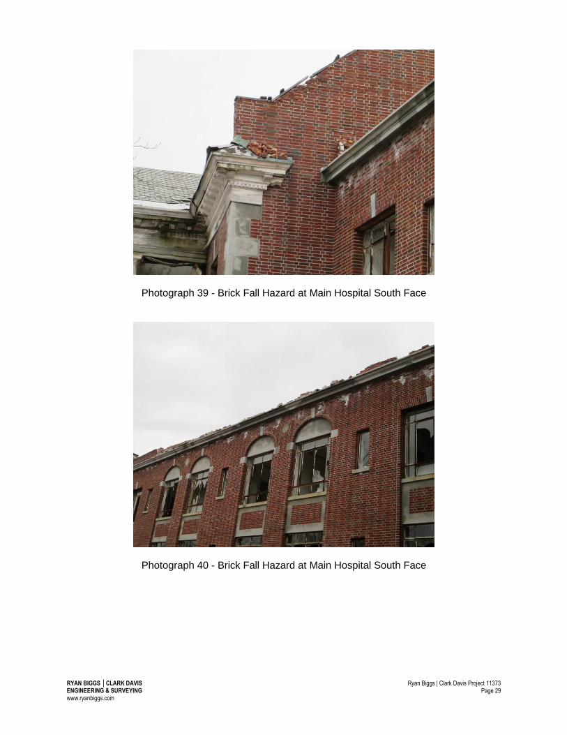
Photograph 31 – Path from West Wing Stair to Doorway of Central Roof Top Structure Photographs 32 to 40 depict areas at the roof perimeter where visual observation from the ground elevation yielded evidence of unstable structural or architectural elements. As described in the General Building Safety Hazards section, Item #6, access near the building perimeter should be limited to avoid injury from falling objects.
Photograph 32 – Displaced Cornice at West Wing Main Hospital

RYAN BIGGS │CLARK DAVIS Ryan Biggs | Clark Davis Project 11373 ENGINEERING & SURVEYING Page 26 www.ryanbiggs.com
Photograph 33 – Crumbling Brick at Parapet of West Wing Main Hospital
Photograph 34 – Crumbling Brick at Parapet of West Wing Main Hospital

RYAN BIGGS │CLARK DAVIS Ryan Biggs | Clark Davis Project 11373 ENGINEERING & SURVEYING Page 27 www.ryanbiggs.com
Photograph 35 – Crumbling Brick at Leaning Parapet of West Wing Main Hospital
Photograph 36 – Deteriorated Brick and Compromised Awning near Children’s Wing Rear Entry

RYAN BIGGS │CLARK DAVIS Ryan Biggs | Clark Davis Project 11373 ENGINEERING & SURVEYING Page 28 www.ryanbiggs.com
Photograph 37 – Brick Fall Hazard at Children’s Wing Entry
Photograph 38 – Brick Fall Hazard at Main Hospital South Face
RYAN BIGGS │CLARK DAVIS Ryan Biggs | Clark Davis Project 11373 ENGINEERING & SURVEYING Page 29 www.ryanbiggs.com
Photograph 39 - Brick Fall Hazard at Main Hospital South Face
Photograph 40 - Brick Fall Hazard at Main Hospital South Face

RYAN BIGGS │CLARK DAVIS Ryan Biggs | Clark Davis Project 11373 ENGINEERING & SURVEYING Page 30 www.ryanbiggs.com
Comments Unsafe conditions within and around the structure are primarily related to the deterioration of the structure due to exposure to water and activities of vandalism. General Building Safety Hazards include 1) falling material hazards from deteriorated architectural finishes and cladding, damaged or partially demolished interior partitions, 2) potential overload in areas and hazardous walking surfaces due to piled debris from previous partial redevelopment activities, 3) deteriorated or collapsed areas of roof framing in and around holes in the structural roof deck, and 4) falling brick and other building material hazards at the exterior building perimeter. Specific Building Safety Hazard areas of the structure where visual observation has revealed structure that is in a state of damage or deterioration where it is no longer capable of safely supporting occupancy loading have been identified and indicated with photographs referenced to the partial building plans included in Figures 1 to 6. In all cases, access to the building and immediate exterior perimeter should be limited to persons having specific knowledge of the building hazards present. If occupancy by authorized personnel in or around areas indicated as unsafe in this report are required, remedial framing and shoring should be provided by a registered professional structural engineer. Ryan Biggs | Clark Davis can be retained to provide specific shoring, support, or recommendations on a case by case basis to allow safe entry and work. Thank you for this opportunity to provide structural engineering evaluation services to you on this project. Please call me if you have questions.
Sincerely, RYAN BIGGS | CLARK DAVIS ENGINEERING & SURVEYING, P.C.
Otto J. Schwarz, P.E., S.E. Associate