real-time damping of power grid oscillations using
TRANSCRIPT

Photos placed in horizontal position
with even amount of white space
between photos and header
Real-Time Damping of Power Grid Oscillations
Using Synchrophasor Feedback
David Schoenwald
Electric Power Systems Research Department
Sandia National Laboratories
CURENT Power and Energy Industry Seminar, March 1, 2019Sandia National Laboratories is a multimission laboratory managed and operated by National Technology and Engineering Solutions of Sandia, LLC, a wholly owned subsidiary of
Honeywell International, Inc., for the U.S. Department of Energy’s National Nuclear Security Administration under contract DE-NA0003525. SAND2019-2114 PE

Outline of Talk
• Project Background
• Control Approach
• Test Results
• PMU Data Considerations
• Studies with other Actuators
• Conclusions and Future Research
2

Acknowledgements and Contributors
• Bonneville Power
Administration (BPA):
– Dmitry Kosterev (Tech. POC)
– Gordon Matthews (PM)
– Jeff Barton
– Tony Faris
– Dan Goodrich
– Michael Overeem
– Sergey Pustovit
– Greg Stults
– Mark Yang
– Steve Yang
• Sandia:
– Dave Schoenwald (PI)
– Brian Pierre
– Felipe Wilches-Bernal
– Ryan Elliott
– Ray Byrne
– Jason Neely
• Montana Tech:
– Dan Trudnowski (co-PI)
– Matt Donnelly
• We gratefully acknowledge the support of DOE and BPA:
– DOE-OE Transmission Reliability Program – PM: Phil Overholt
– DOE-OE Energy Storage Program – PM: Imre Gyuk
– BPA Office of Technology Innovation – TIP# 289
3

Problem:
• Large generation and load centers separated by long transmission corridors can develop inter-area oscillations
• Poorly damped inter-area oscillations jeopardize grid stability and can lead to widespread outages during high demand
• To prevent this, utilities constrain power flows well below transmission ratings inefficient
Solution:
• Construct closed-loop feedback signal using real-time PMU (Phasor Measurement Unit) data: 1st demonstration of this in North America
• Modulate power flow on PDCI (Pacific DC Intertie)up to +/- 125 MW
• Implement a supervisory system to ensure “Do No Harm” to grid and monitor damping effectiveness
Benefits:
• Improved grid reliability
• Additional contingency for stressed grid conditions
• Avoided costs from a system-wide blackout (>> $1B)
• Reduced or postponed need for new transmission capacity: $1M–$10M/mile
• Helps meet growing demand by enabling higher power flows on congested corridors
Damping Controller Overview
4

Inter-Area Oscillations Jeopardize Grid Stability
Western Power System Breakup on August 10, 1996
5

Project Background
▪ Based on 1970s BPA experiments on PDCI
later shown to have destabilized BC-US mode
▪ Revived in 2007 – 2012 by BPA with Montana
Tech leveraging PMU deployments in WECC
▪ Current project launched in June 2013 as a
collaboration of SNL, MT, BPA, and DOE to
develop and demonstrate damping control
▪ Phase 1 (June 2013 – Sept 2015)
• Controller design based on extensive
simulation studies & eigensystem analysis
• Open-loop tests – study PMU data quality
▪ Phase 2 (Oct 2015 – Sept 2017)
• System install at Celilo in The Dalles, OR
• Closed-loop demonstration on Western
Interconnection using modulation of PDCI
• Documentation and publishing of results;
engagement of power systems community
▪ Phase 3 (Oct 2017 and beyond)
• Conduct longer-term tests
• Study transient stability potential
• Assess impacts with DC side
• Explore other sources of actuation
6
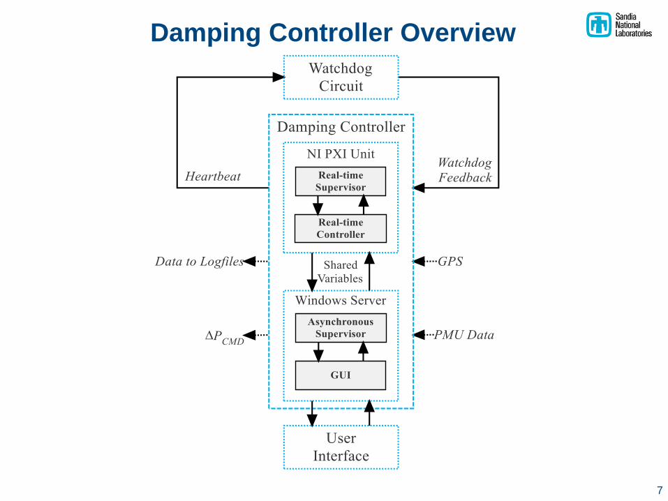
Damping Controller Overview
7
PDCIWestern
Inter-connection
VSouth
VNorthPMUNorth
PMUSouth
ControllerGain
Module
Δf
Pscheduled
Pmax
-Pmax
Pcommand
Disturbances
H(z)
H(z)
fSouth
fNorth
–
+
θNorth
θSouth
Damping Controller
PDC
+
+
21
34
5
1
2
3
4
5
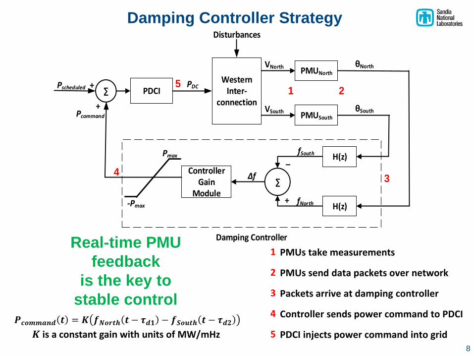
PMUs take measurements
PMUs send data packets over network
Packets arrive at damping controller
Controller sends power command to PDCI
PDCI injects power command into grid
Damping Controller Strategy
8
𝑷𝒄𝒐𝒎𝒎𝒂𝒏𝒅 𝒕 = 𝑲 𝒇𝑵𝒐𝒓𝒕𝒉 𝒕 − 𝝉𝒅𝟏 − 𝒇𝑺𝒐𝒖𝒕𝒉 𝒕 − 𝝉𝒅𝟐
𝑲 is a constant gain with units of MW/mHz
Real-time PMU
feedback
is the key to
stable control

Controller Employs Diversity
and Redundancy in Feedback
9
• Diversity = Geographical Robustness
• Redundancy = Site Measurement Robustness
• Controller evaluates 16 feedback pairs every update cycle
to provide options due to any network issues
• Controller seamlessly switches between feedback pairs
to avoid injecting step functions into the system

Design was driven by the need to detect and respond to certain
system conditions in real-time as well as asynchronous
monitoring functions at slower than real time
10
Supervisor Design Philosophy

Watchdog circuit module
Real-time Control platform
Server for select supervisory functions(“Do No Harm”)
Damping Controller Hardware
11
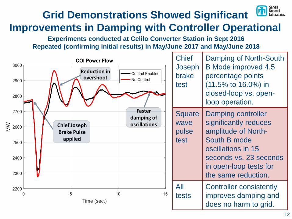
Grid Demonstrations Showed Significant
Improvements in Damping with Controller OperationalExperiments conducted at Celilo Converter Station in Sept 2016
Repeated (confirming initial results) in May/June 2017 and May/June 2018
Chief
Joseph
brake
test
Damping of North-South
B Mode improved 4.5
percentage points
(11.5% to 16.0%) in
closed-loop vs. open-
loop operation.
Square
wave
pulse
test
Damping controller
significantly reduces
amplitude of North-
South B mode
oscillations in 15
seconds vs. 23 seconds
in open-loop tests for
the same reduction.
All
tests
Controller consistently
improves damping and
does no harm to grid.
Chief Joseph Brake Pulse
applied
Faster damping of oscillations
Reduction in overshoot
12
13
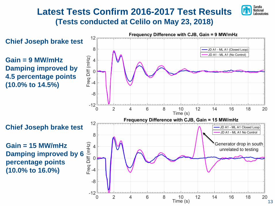
Latest Tests Confirm 2016-2017 Test Results(Tests conducted at Celilo on May 23, 2018)
Generator drop in south
unrelated to testing
Gain = 9 MW/mHz
Damping improved by
4.5 percentage points
(10.0% to 14.5%)
Gain = 15 MW/mHz
Damping improved by 6
percentage points
(10.0% to 16.0%)
Chief Joseph brake test
Chief Joseph brake test

14
Gain Tuning was Informed by Square Wave Pulses(Tests conducted at Celilo on May 23, 2018)
Lower gains less damping improvement
Higher gains more “ringing” on the DC side
Sweet spot K = 12 to 15 MW/mHz

May 16, 2017 Tests, 0.4 Hz Forced Oscillation
15
16
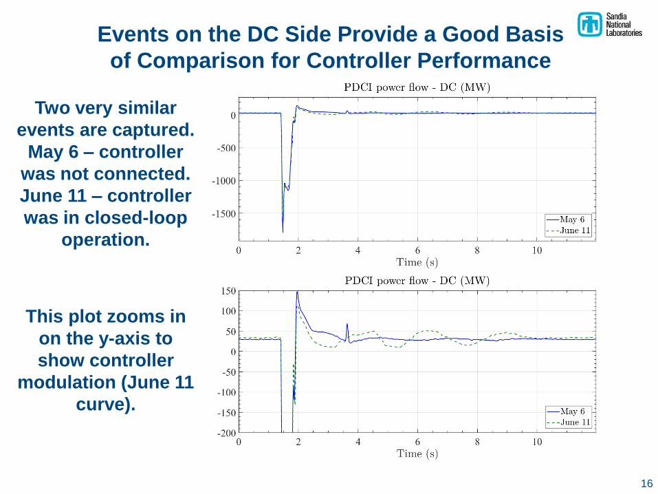
Events on the DC Side Provide a Good Basis
of Comparison for Controller Performance
Two very similar
events are captured.
May 6 – controller
was not connected.
June 11 – controller
was in closed-loop
operation.
This plot zooms in
on the y-axis to
show controller
modulation (June 11
curve).
17
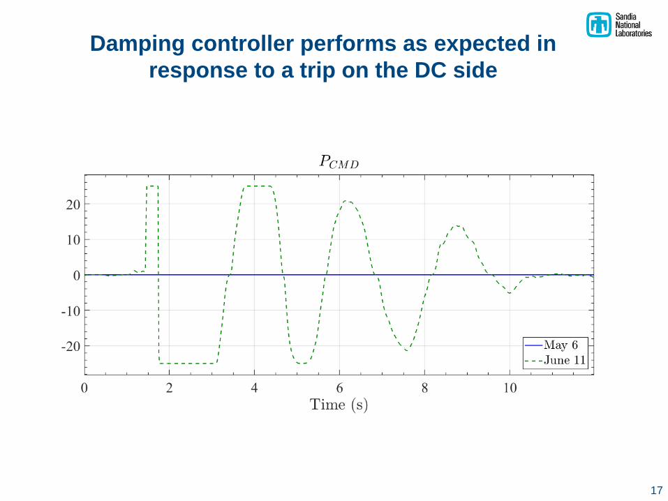
Damping controller performs as expected in
response to a trip on the DC side

time
PMU Delay Communication Delay
Control
Processing
Delay
Command Delay
1 2 3 4 5
PMUs take
measurements
PMUs send
data packets
Packets
arrive at
controller
Controller
dispatches
command PDCI acts
Communication and Delays
Name Mean Range Note
PMU
Delay44 40 – 48
Dependent on PMU settings.
Normal distribution.
Communication
Delay16 15 – 40 Heavy tail
Control
Processing
Delay
11 2 – 17
Normal around 9 ms, but a peak
at 16 ms due to control windows
when no data arrives (inconsistent
data arrival)
Command
Delay11 11 Tests were consistent, fixed 11 ms
Effective Delay 82 69 – 113 Total delay
Total time delays are well within our tolerances (<< 150 ms)
18

PMU Data Considerations
• PMUs have inconsistent interpacket delays
19
• Delay inconsistency also affects the power command
Delay inconsistency
affects frequency
estimation
Ideal caseDelay inconsistency
with NO time alignment
Delay inconsistency
with time alignment

PMU Data Considerations
• Time alignment
- The North and South
measurements need to have
the same PMU timestamp
- Supervisory system time
aligns the data
- If data is too far apart, the
control instance is disabled
• Other PMU data issues
- Data dropout:
Supervisory system catches
data dropouts and disables
that controller instance
- Corrupted data:
Supervisory system flags
irregular data (e.g. repeated
values, missing time stamps)
20

Advantages:
• Robust to single points of failure
• Controllability of multiple modes
• Size/location of a single site not
critical as more distributed energy
resources are deployed on grid
• With 10s of sites engaged, single
site power capability ≈ 1 MW can
provide improved damping
• Control signal is energy neutral
and short in time duration sites
can perform other applications
Damping Control Using Distributed
Energy Resources
21
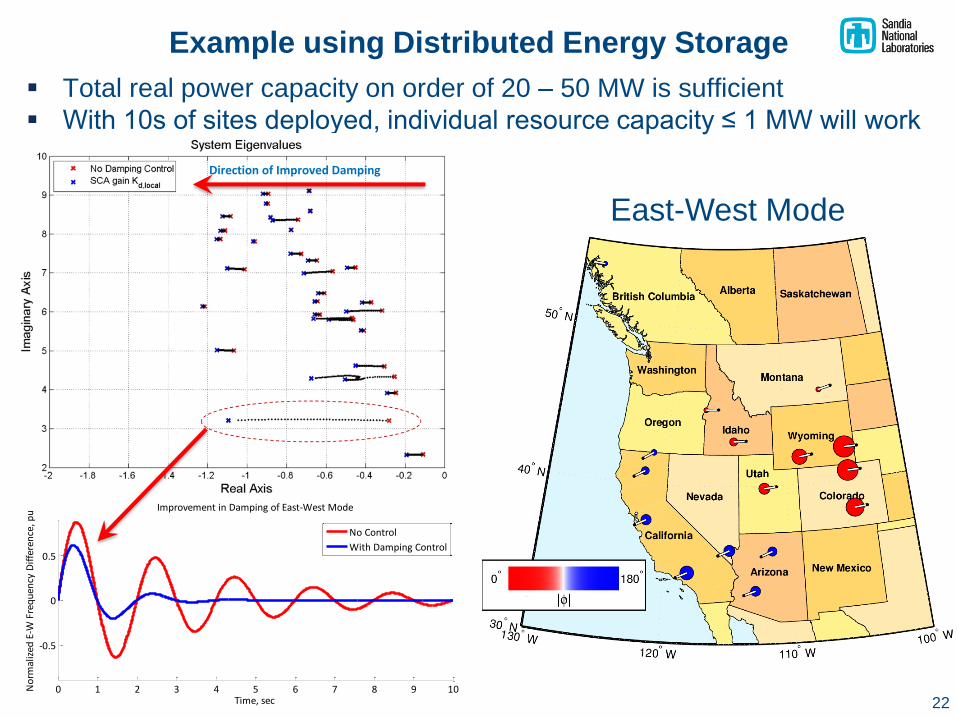
Example using Distributed Energy Storage
▪ Total real power capacity on order of 20 – 50 MW is sufficient
▪ With 10s of sites deployed, individual resource capacity ≤ 1 MW will work
0 1 2 3 4 5 6 7 8 9 10
-0.5
0
0.5
Improvement in Damping of East-West Mode
Time, sec
No
rmal
ized
E-W
Fre
qu
ency
Dif
fere
nce
, pu
No Control
With Damping Control
Direction of Improved Damping
East-West Mode
22
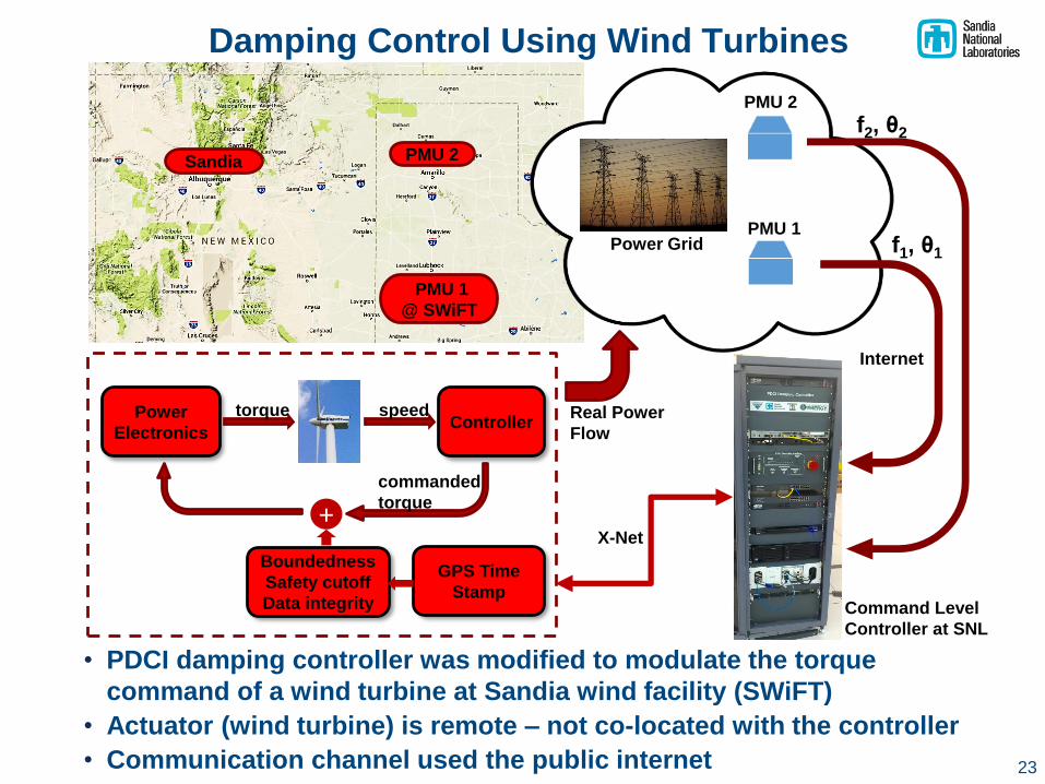
Damping Control Using Wind Turbines
23
• PDCI damping controller was modified to modulate the torque
command of a wind turbine at Sandia wind facility (SWiFT)
• Actuator (wind turbine) is remote – not co-located with the controller
• Communication channel used the public internet
ControllerPower
Electronics
torque speed
+
Boundedness
Safety cutoff
Data integrity
commanded
torque
Command Level
Controller at SNL
X-Net
PMU 2
PMU 1Power Grid
Internet
GPS Time
Stamp
f2, θ2
Real Power
Flow
f1, θ1
Sandia
PMU 1
@ SWiFT
PMU 2

Key Takeaways from Project
• First successful demonstration of wide-area control using real-time
PMU feedback in North America much knowledge gained for
networked control systems
• Control design is actuator agnostic easily adaptable to other
sources of power injection (e.g., wind turbines, energy storage)
• Supervisory system architecture and design can be applied to
future real-time grid control systems to ensure “Do No Harm”
• Algorithms, models, and simulations to support implementation of
control strategies using distributed grid assets
• Extensive eigensystem analysis and visualization tools to support
simulation studies and analysis of test results
• Model development and validation for multiple levels of fidelity to
support analysis, design, and simulation studies
24

Project Recognition
• First successful demonstration of wide-area control using
real-time PMU feedback in North America
• 2017 R&D 100 Award
• 19 published papers (17 conference papers, 2 journal papers,
several more journal papers in review process)
• US Patent application filed March 2018
• Commercialization of DCON being pursued jointly with BPA
25

Current Status
• We are teaming with a software firm to “harden” the software
to be operational in a substation environment
• We are leveraging the actuator “agnosticism” to widen the
potential commercial market beyond the initial high voltage
DC application with BPA
• We are enabling the “modularization” of the damping
controller to be easily adaptable to other environments
(energy storage, wind, large PV plants, etc.)
• Interested vendors include ABB and Schweitzer Engineering
Labs
26

Future Research Recommendations
➢ Control designs to improve transient stability and voltage stability
on transmission grids
➢ Assessment & mitigation of forced oscillations on transmission
grids (both AC and HVDC)
➢ Enhancements to improve resilience of transmission grids
• Design of control architectures that are more robust to single
points of failure (e.g. decentralized control)
• Control designs that leverage large #’s of distributed assets (e.g.
power sources, measurement systems) to improve performance
and reliability of transmission grids
➢ Analytics to improve transmission reliability
• Real-time PMU data represents an enormous amount of data:
How does one manage this amount of data?
How can one leverage the data for key information?
Potential techniques include machine learning
27