receiving and inspection - ruppair
TRANSCRIPT
A0011028 June 2018 Rev 19
CELDEK Evaporative Cooler Module
Installation, Operation, and Maintenance Manual
CELDEK Evaporative Cooler
Save these instructions: This document is the property of the owner of this equipment and is required for future maintenance. Leave this document with the owner when installation or service is complete.
RECEIVING AND INSPECTION Upon receiving unit, check for any interior and exterior damage, and if found, report it immediately to the carrier. Also check that all accessory items are accounted for and are damage free.
WARNING!!
Installation of this module should only be performed by a qualified professional who has read and understands these instructions and is familiar with proper safety precautions. Improper installation poses serious risk of injury due to electric shock, and other potential hazards. Read this manual thoroughly before installing or servicing this equipment. ALWAYS
disconnect power prior to working on module.

2

3
TABLE OF CONTENTS WARRANTY .................................................................................................................................................. 4 INSTALLATION ............................................................................................................................................. 5
Mechanical ................................................................................................................................................ 5 Site Preparation .................................................................................................................................... 5 Assembly .............................................................................................................................................. 5 Roof Mount Installation ......................................................................................................................... 7 Indoor (Inline) Installation ..................................................................................................................... 8 LPD Celdek Evaporative Cooler Adapter Plate Installation Instructions .............................................. 9
Electrical ................................................................................................................................................. 10 OPERATION ............................................................................................................................................... 11
Freeze Protection ................................................................................................................................... 11 Timer Settings ......................................................................................................................................... 12 Nozzle Replacement ............................................................................................................................... 14 Water Strainer ......................................................................................................................................... 15 Start Up ................................................................................................................................................... 16
Special Tools Required ...................................................................................................................... 16 Start Up Procedure ............................................................................................................................. 16
Component Description/Detail ................................................................................................................ 17 Troubleshooting .......................................................................................................................................... 18
Troubleshooting Chart ........................................................................................................................ 18 MAINTENANCE .......................................................................................................................................... 19
General Maintenance ............................................................................................................................. 19 Every 3 months ....................................................................................................................................... 19 Yearly ...................................................................................................................................................... 19 Start-Up and Maintenance Documentation ............................................................................................ 20

4
WARRANTY This equipment is warranted to be free from defects in materials and workmanship, under normal use and service, for a period of 24 months from date of shipment. This warranty shall not apply if:
1. The equipment is not installed by a qualified installer per the MANUFACTURER’S installation instructions shipped with the product.
2. The equipment is not installed in accordance with federal, state and local codes and regulations.
3. The equipment is misused or neglected, or not maintained per the MANUFACTURER’S maintenance instructions.
4. The equipment is not operated within its published capacity.
5. The invoice is not paid within the terms of the sales agreement.
The MANUFACTURER shall not be liable for incidental and consequential losses and damages potentially attributable to malfunctioning equipment. Should any part of the equipment prove to be defective in material or workmanship within the 24 month warranty period, upon examination by the MANUFACTURER, such part will be repaired or replaced by MANUFACTURER at no charge. The BUYER shall pay all labor costs incurred in connection with such repair or replacement. Equipment shall not be returned without MANUFACTURER’S prior authorization and all returned equipment shall be shipped by the BUYER, freight prepaid to a destination determined by the MANUFACTURER.

5
INSTALLATION It is imperative that this unit is installed and operated with the designed airflow and electrical supply in accordance with this manual. If there are any questions about any items, please call the service department at 1-866-784-6900 for warranty and technical support issues.
Mechanical
WARNING: DO NOT RAISE VENTILATOR BY THE INTAKE HOOD, FILTER TRACKS, OR PIPING – USE LIFTING LUGS PROVIDED OR A SLING
Site Preparation
Table 1 – Service Clearance 1. Provide clearance around installation site to safely rig and lift
equipment into its final position. Supports must adequately support equipment. Refer to manufacturer’s estimated weights.
2. Consider general service and installation space when locating unit. Use the clearance chart for clearance specification on control side.
3. Do not allow air intake to face prevailing winds. Support unit above ground or at roof level high enough to prevent precipitation from being drawn into its inlet. The inlet must also be located at least 10 feet away from any exhaust vents.
Assembly
There are several items shipped loose with the evaporative coolers. These items include the drain trap components, sheet metal screws, nuts and bolts, screen intakes (for outdoor installations), equipment legs (for outdoor installations), and hanging cradles (option for indoor applications). Upon unit arrival, follow the following procedure to assemble the evaporative cooler:
1. Attach the evaporative cooler to the ventilator or duct using the sheet metal screws and nuts and bolts included. Ensure that there is a liquid tight seal formed between the evaporative cooler and the ventilator.
2. Screw the flanges of the intake screen to the unit with the supplied sheet metal screws. (Outdoor installations only).
3. Fans designed for outdoor installation are provided with adjustable equipment legs. The adjustable legs should be used to support and level the front end of the evaporative cooler.
Size Clearance (inch)
1 30”
2 38”
3 42”
4 49”
5 60”
6 78”
Ventilator Evaporative
Cooler
Curb Equipment Legs
Screen Intake
Drain Trap Assembly
Liquid Tight Conduit
Figure 1 - Assembly
6
Plumbing Connections
There are two field plumbing connections required for proper evaporative cooler operation. It is recommended that all plumbing connections be sealed with Teflon tape or pipe dope. Use care not to contaminate the interior surfaces of the water lines when plumbing the unit, as small particulate can clog the orifices of the spray nozzles.
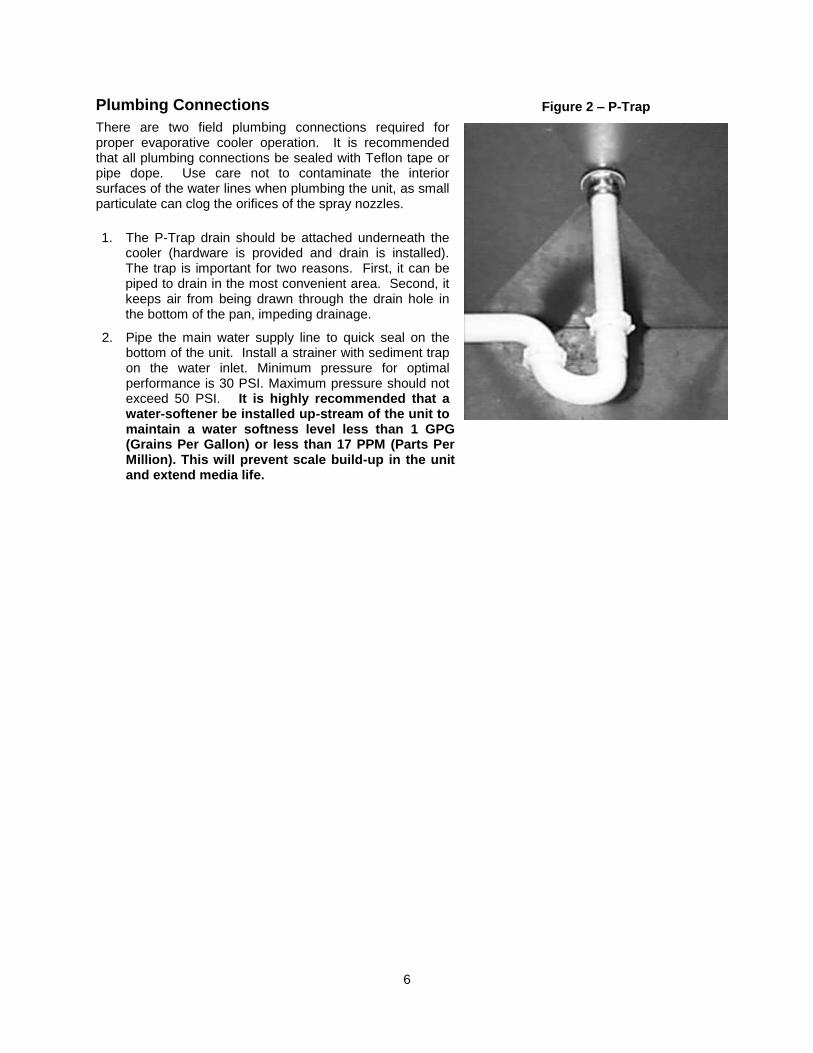
1. The P-Trap drain should be attached underneath the cooler (hardware is provided and drain is installed). The trap is important for two reasons. First, it can be piped to drain in the most convenient area. Second, it keeps air from being drawn through the drain hole in the bottom of the pan, impeding drainage.
2. Pipe the main water supply line to quick seal on the bottom of the unit. Install a strainer with sediment trap on the water inlet. Minimum pressure for optimal performance is 30 PSI. Maximum pressure should not exceed 50 PSI. It is highly recommended that a water-softener be installed up-stream of the unit to maintain a water softness level less than 1 GPG (Grains Per Gallon) or less than 17 PPM (Parts Per Million). This will prevent scale build-up in the unit and extend media life.
Figure 2 – P-Trap
7
Liquid Tight
Conduit
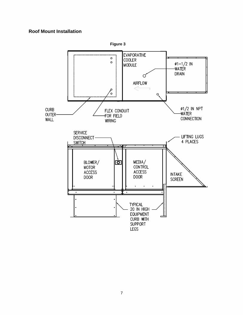
Roof Mount Installation
Figure 3

8
Indoor (Inline) Installation
Figure 4
9
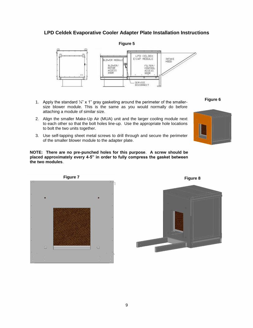
LPD Celdek Evaporative Cooler Adapter Plate Installation Instructions
1. Apply the standard ¼” x 1” gray gasketing around the perimeter of the smaller-size blower module. This is the same as you would normally do before attaching a module of similar size.
2. Align the smaller Make-Up Air (MUA) unit and the larger cooling module next to each other so that the bolt holes line-up. Use the appropriate hole locations to bolt the two units together.
3. Use self-tapping sheet metal screws to drill through and secure the perimeter of the smaller blower module to the adapter plate.
NOTE: There are no pre-punched holes for this purpose. A screw should be placed approximately every 4-5” in order to fully compress the gasket between the two modules.
Figure 5
Figure 6
Figure 7 Figure 8

10
Table 2 - Copper Wire Ampacity
Wire Size AWG
Maximum Amps
14 15
12 20
10 30
8 50
6 65
4 85
Electrical
Before connecting power to the module, read and understand the entire section of this document. As-built wiring diagrams are furnished with each module by the factory, and are attached either to the door of the unit or provided with a paperwork packet. Electrical wiring and connections should be done in accordance with local ordnances and the National Electric Code, ANSI/NFPA70. Be sure the voltage and phase of the power supply and the wire amperage capacity is in accordance with the unit nameplate. For additional safety information refer to AMCA publication 410-96, Recommended Safety Practices for Users and Installers of Industrial and Commercial Fans.
1. Always disconnect power before working on or near this equipment. Lock and tag the disconnect switch or breaker to prevent accidental power up.
2. An electrical drop containing the line voltage power wiring is shipped with every evaporative cooler. The electrical drop should be brought through one of the conduit openings located in the front of the module and connected to an appropriate power source.
3. Make certain that the power source is compatible with the requirements of your equipment. The evaporative cooler wiring schematic identifies the proper phase and voltage of the equipment.
4. Before connecting evaporative cooler to power source, verify power line wiring is de-energized.
5. Secure the power cable to prevent contact with sharp objects.
6. Do not kink power cable and never allow the cable to come in contact with oil, grease, hot surfaces or chemicals.
7. Before powering up the evaporative cooler make sure that the interior of the unit is free of loose debris or shipping materials.
8. If any of the original wire supplied with the cooler must be replaced, it must be replaced with type THHN wire or equivalent.
WARNING!!
Disconnect power before installing or servicing module. High voltage electrical input is needed for this equipment. This work should be performed by a qualified electrician.

11
OPERATION Prior to starting up or operating the evaporative cooler, check all fasteners for tightness. Ensure that the cooling media is installed properly and that the interior of the cooler is free of loose debris. The evaporative cooler is equipped with a 2 setting timer control. The UPPER 2 dials are used to denote the length of time the manifold sprays water while the LOWER 2 dials control the amount of time between spray periods. Both of these settings are factory set and should not have to be adjusted during initial installation of the unit. It is important to understand that the spray timing pattern is cyclic in nature with the manifold discharging water on and off continuously based on the timers dial settings. The Celdek evaporative coolers are shipped from the factory with specific nozzles with varying characteristics regarding flow rates and anti-drip protection. It is imperative that the correct nozzle is used in the correct location and type of cooling module to ensure quality performance and leakage prevention. Information regarding the nozzles and timer control should be read and understood before commencing unit start-up procedures.
Freeze Protection On units shipped with the optional freeze protection drain kit, additional field wiring and piping is required. A 3-way water solenoid is provided; containing a normally open and a normally closed valve. This 3-way solenoid should be installed below the roof line. Additional details on how to install this 3-way solenoid are included in the Component Detail section (page 17) of this manual. A 2-stage thermostat is also provided in the evaporative cooler when the freeze protection option is ordered. The evaporative cooler will automatically drain when the ambient temperature falls below the internal two stage thermostat set-point.
Figure 9 – Optional Freeze Protection Kit
To building
drain
From building
water supply
Roof line
Field Wired
and Piped

12
Timer Settings Figure 10
Both the upper and lower timer settings are adjusted using the same procedure. The UPPER section controls the length of time the manifold sprays water, while the LOWER section controls the amount of time between spray periods. Both of these parameters are set in the factory and should not have to be adjusted during initial start-up. If adjustments to airflow are made, the timer settings will need to be adjusted to sustain proper performance.

13
The procedure for setting the Timer control is as follows:
1) Set the two coarse time setting dials to “1 MIN”. THESE ARE ALWAYS SET TO “1 MIN” FOR
ALL UNITS REGARDLESS OF SIZE AND TYPE.
2) Set the “fine time setting off” dial located on the LOWER portion of the timer. THIS IS ALWAYS SET TO “1.0” FOR ALL UNITS REGARDLESS OF SIZE AND TYPE.
3) Using the table at the bottom of this page, calculate the time parameter of how many seconds the manifold will spray based on the given CFM of the unit.
4) Set the “fine time setting on” dial located on the UPPER portion of the timer. For each time parameter, the values of both the fine adjustment and coarse adjustment dials are multiplied by one another to denote the total time of the parameter. The fine time setting dials are percentages of the course time settings. For example, if the course dial is set to 1 minute, and the fine dial is set to 0.5, the selected time period would result in 30 (1 minute * 0.5 = 30 Sec) seconds. Check to ensure that the parameter for “spray time on” matches the amount of time calculated in step 3.
Table 3
Unit Size *Time "Spray - On" (LOWER timer setting in SEC.)
1 CFM*(15/3000) + 6.5
2 CFM*(15/4000) + 1.5
3 CFM*(15/4500) - 1
4 CFM*(15/9000) - 1
5 CFM*(15/12,000) - 3.5
6 CFM*(15/15,000) - 5
*NOTE: THE VALUE GENERATED FROM THE EQUATIONS IN THE TABLE IS FOR SECONDS THAT THE MANIFOLD IS TO SPRAY WATER. IT IS NOT THE FINE DIAL SETTING. STEP “4” MUST BE CARRIED OUT IN ORDER TO PROPERLY SET THE FINE TIME SETTING ON DIAL.
14
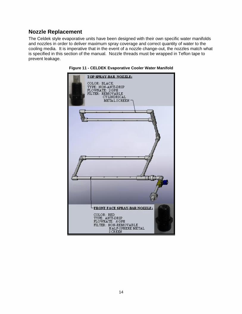
Nozzle Replacement The Celdek style evaporative units have been designed with their own specific water manifolds and nozzles in order to deliver maximum spray coverage and correct quantity of water to the cooling media. It is imperative that in the event of a nozzle change-out, the nozzles match what is specified in this section of the manual. Nozzle threads must be wrapped in Teflon tape to prevent leakage.
Figure 11 - CELDEK Evaporative Cooler Water Manifold
15
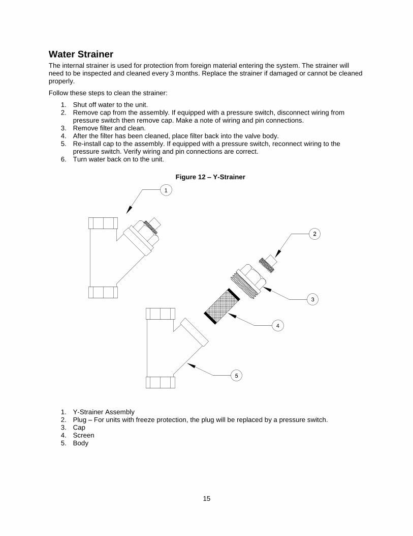
Water Strainer The internal strainer is used for protection from foreign material entering the system. The strainer will need to be inspected and cleaned every 3 months. Replace the strainer if damaged or cannot be cleaned properly.
Follow these steps to clean the strainer:
1. Shut off water to the unit. 2. Remove cap from the assembly. If equipped with a pressure switch, disconnect wiring from
pressure switch then remove cap. Make a note of wiring and pin connections. 3. Remove filter and clean. 4. After the filter has been cleaned, place filter back into the valve body. 5. Re-install cap to the assembly. If equipped with a pressure switch, reconnect wiring to the
pressure switch. Verify wiring and pin connections are correct. 6. Turn water back on to the unit.
1. Y-Strainer Assembly 2. Plug – For units with freeze protection, the plug will be replaced by a pressure switch. 3. Cap 4. Screen 5. Body
Figure 12 – Y-Strainer
1

16
Start Up
Special Tools Required
AC Voltage Meter
Amperage Meter
Standard Hand Tools
Start Up Procedure
1. Remove the access door and check all electrical connections for tightness and continuity.
2. Inspect the air-stream for obstructions and install cooling media if missing.
3. Compare the supplied voltage with the unit’s nameplate voltage. If this does not match, correct the problem.
4. Set the internal thermostat to a set-point cooler than the entering air temperature for start-up purposes. The cooling circuit will be energized when the entering air temperature is hotter than the thermostat set-point.
5. Check the timers dial settings. Ensure that the timer’s settings match what is specified in the above section of this manual under Timer Settings (page 12).
6. Install the access door and apply power to the unit. If the entering air temperature is hotter than the thermostat set-point, the cooling circuit will be energized and water will begin spraying from the nozzles. If no water sprays, the unit is either not powered, has no water pressure or the entering air temperature is cooler than the thermostat set-point.
7. Observe the spray timing sequence. Make sure that the sequence observed matches what is specified based on CFM to optimize evaporative cooler performance. The unit should spray enough to keep the media wet with minimal run-off and light drainage. It takes roughly 20 minutes for the cooling media to become fully saturated and come up to steady state operating conditions. If there is no water in the drain pan and no run-off of the media, the “spray-time on” parameter should be increased to lengthen the time water is sprayed. If there is excessive runoff and quantities of drainage, the “spray-time on” parameter should be decreased to shorten the time water is sprayed. Set the thermostat back to the desired cooling temperature (typically about 85°F). Remember, the cooling circuit will only be energized when the entering air temperature is higher than the set-point.
17
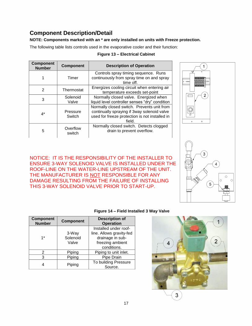
Component Description/Detail NOTE: Components marked with an * are only installed on units with Freeze protection.
The following table lists controls used in the evaporative cooler and their function:
Figure 13 – Electrical Cabinet
NOTICE: IT IS THE RESPONSIBILITY OF THE INSTALLER TO ENSURE 3-WAY SOLENOID VALVE IS INSTALLED UNDER THE ROOF-LINE ON THE WATER-LINE UPSTREAM OF THE UNIT. THE MANUFACTURER IS NOT RESPONSIBLE FOR ANY DAMAGE RESULTING FROM THE FAILURE OF INSTALLING THIS 3-WAY SOLENOID VALVE PRIOR TO START-UP.
Component Number
Component Description of Operation
1 Timer Controls spray timing sequence. Runs
continuously from spray time on and spray time off.
2 Thermostat Energizes cooling circuit when entering air
temperature exceeds set-point
3 Solenoid
Valve Normally closed valve. Energized when
liquid level controller senses “dry” condition
4* Pressure Switch
Normally closed switch. Prevents unit from continually spraying if 3way solenoid valve used for freeze protection is not installed in
field.
5 Overflow
switch
Normally closed switch. Detects clogged drain to prevent overflow.
Component Number
Component Description of
Operation
1* 3-Way
Solenoid Valve
Installed under roof-line. Allows gravity-fed
drainage in sub-freezing ambient
conditions.
2 Piping Piping to unit inlet.
3 Piping Pipe Drain
4 Piping To building Pressure
Source.
Figure 14 – Field Installed 3 Way Valve

18
Troubleshooting The following table lists causes and corrective actions for possible problems with evaporative coolers. Review this list prior to consulting manufacturer.
Troubleshooting Chart
Problem Potential Cause Corrective Action Insufficient Cooling
Media not wet Check for even spray pattern from all nozzles
Clogged nozzles Clean or replace nozzles
Timer Settings improperly set
Ensure that the timers dial setting settings correspond to those specified in the reference table of this manual based on face velocity.
Internal thermostat set to high
Set thermostat to lower setting. Cooling circuit will be energized when the outside air temperature is higher than thermostat set-point
No water pressure Turn main building water valve on
Insufficient water spray Check water strainer. Refer to Water Strainer (page 15)
Clogged drain causing pan overflow switch to activate
Clear any debris from drain and ensure bottom pan drains properly. Ensure that the overflow switch float mechanism is able to travel up and down freely
Excessive ambient humidity
Wrong application for evaporative cooling
Cooling media dirty Clean or replace cooling media
Insufficient Airflow
Cooling media clogged Clean or replace cooling media
Excessive Airflow
Cooling media missing Install cooling media

19
Figure 15 - CELDEK Installation
Intake Quantity Size
Size 1 CELDEK 1 24” x 20”
Size 2 CELDEK 1 32” x 25”
Size 3 CELDEK 1 36” x 30”
Size 4 CELDEK 1 43” x 38”
Size 5 CELDEK 1 54” x 45”
Size 6 CELDEK 1 72” x 45”
MAINTENANCE To guarantee trouble free operation of this evaporative cooler, the manufacturer suggests following these guidelines. Most problems associated with unit failures are directly related to poor service and maintenance.
Please record any maintenance or service performed on this equipment in the documentation section located at the end of this manual.
WARNING: DO NOT ATTEMPT MAINTENANCE ON THE EVAPORATIVE COOLER UNTIL THE ELECTRICAL SUPPLY HAS BEEN COMPLETELY DISCONNECTED
General Maintenance 1. Inlet and approaches to evaporative cooler should be kept clean and free from any obstruction.
2. All fasteners should be checked for tightness each time maintenance checks are performed prior to restarting unit.
3. Evaporative coolers require little attention when moving clean air. Occasionally oil and dust may accumulate on cooling media causing low airflow or reduced cooling. Cooling media should be inspected and cleaned every 3 months and replaced every cooling season.
Every 3 months 1. Cooling media needs to be cleaned and/or replaced (if damaged)
quarterly, and more often in severe conditions. Cooling media can be washed with a standard water hose. When re-installing cooling media, be sure to install with the airflow in the correct direction. The CELDEK media should be installed with the 15° holes along the air stream path as indicated in the CELDEK installation illustration.
2. Inspect and clean water strainer. Refer to Water Strainer on (page 15).
3. Check all fasteners, sensors and electrical connections for proper tightness and continuity.
4. Check all nozzles for proper and evenly distributed water flow. If nozzles are clogged, clean or replace.
Yearly 1. Replace cooling media prior to cooling season.
Cooling media should be replaced yearly to guarantee proper cooling performance. The following table illustrates proper media quantities and sizes.
2. Check the piping manifold and evaporative cooler housing for water tightness. Replace or repair any leaking or damaged components.
3. Every cold season requires that the evaporative cooler water piping system be drained to prevent freezing and cracking of the water piping. The main water supply should also be turned off for the cold season.
Table 4 - Cooling Media Size and Quantity

20
Start-Up and Maintenance Documentation START-UP AND MEASUREMENTS SHOULD BE PERFORMED AFTER THE SYSTEM HAS BEEN AIR BALANCED (Warranty will be void without completion of this form)
Job Information
Job Name Service Company
Address Address
City City
State State
Zip Zip
Phone Number Phone Number
Fax Number Fax Number
Contact Contact
Purchase Date Start-Up Date
Evaporative Cooler Information Refer to the start-up procedure in this manual to complete this section.
Name Plate and Unit Information Field Measured Information
Model Number Voltage
Serial Number Thermostat Set-Point °F
Volts Time spray on (Sec)
Hertz
Time spray off (Sec)
Phase Airflow Direction Correct
Incorrect
Maintenance Record
Date Service Performed
Factory Service Department Phone: 1-866-784-6900
Fax: 1-919-554-9374