recommended layout of instrumentation to monitor potential...
TRANSCRIPT
GRI White Paper #19
Recommended Layout of Instrumentation to Monitor Potential Movement of MSE Walls, Berms and Slopes
Robert M. Koerner, Ph.D., P.E., NAE George R. Koerner, Ph.D., P.E., CQA Director – Geosynthetic Institute Director Designate Emeritus Professor – Drexel University Geosynthetic Institute Phone: 610-522-8440 Phone: 610-522-8440 Fax: 610-522-8441 Fax: 610-522-8441 [email protected] [email protected]
April 19, 2011
Geosynthetic Institute
475 Kedron Avenue Folsom, PA 19033-1208 USA
TEL (610) 522-8440 FAX (610) 522-8441
GSI
GRI GII
GAI
GEI
GCI
-1-
GRI White Paper #19 Recommended Layout Instrumentation to Monitor Potential Movements of MSE
Walls, Berms and Slopes
1.0 Background
This white paper is one of an ongoing GRI series which focus on various geosynthetic
materials and their applications. All of them are posted on the institute’s website for anyone who
is interested. For this particular white paper, the subject is mechanically stabilized earth (MSE)
walls, berms and steep soil slopes reinforced with either geogrids or geotextiles. MSE
technology was introduced in the 1960’s and initially used steel strips and then steel mesh, with
geosynthetics (first geotextiles and now mainly geogrids) coming on strong beginning in about
1980. Today there are an estimated 40,000 MSE walls, berms and steep slopes reinforced with
geosynthetics in the world and they are the most common of all types. Figure 1 shows typical
cross-sections.
(a) MSE wall with a bridge abutment surcharge (b) Typical MSE berm components in landfill application (after Wu, et al. 2006) (after Luettich, 2010)
(c) Shoulder widening using geogrid reinforced steep soil slopes (after Berg et al, 1990)
(biaxial)
Unconfined Structure
Figure 1 – Typical cross sections of mechanically stabilized walls, berms and slopes using geosynthetic reinforcement.

-2-
Inasmuch as these structures are aesthetically pleasing, adaptable to all types of
conditions, lowest cost of all wall types, and have an extremely low carbon footprint, there have
been failures. Estimates of 2 to 4% of walls have experienced either excessive deformation (to
which this white paper is focused) or collapse (in which case only the remaining standing
sections can be monitored). Koerner and Soong reported on 26 failures in 2001 and then
Koerner and Koerner (2009) subsequently reported on 82 such failures. Of these 82 failures, the
basic causes are distributed as follows:
internal reinforced soil zone instability (26%)
external reinforced soil zone instability (6%)
internal reinforced soil zone water (46%)
external reinforced soil zone water (22%)
Figure 2a shows examples of MSE walls with excessive deformation. These walls should be
considered for monitoring to determine if the deformations are ongoing or if they cease to have
further movement. These are, of course, critical assessments. Figure 2b shows examples of
MSE walls which have collapsed in whole or part. These situations might also be candidates for
monitoring so as to assess if the remaining standing sections on either side of the collapse are
moving or are stable.
The failure situation is recently becoming openly discussed, e.g., GSI (2001, 2009),
Bachus and Griffin (2010), and McKelvey (2011), and it is hoped that the lessons learned will
improve design and construction practices in the very near future. Considering this situation,
however, it appears to the authors that some type of geotechnical instrumentation would be
prudent to install on behalf of owners, designers, and installers. This white paper is focused on

-3-
the minimum amount of recommended instrumentation either prior to (which is desirable) or
after construction of the wall or slope (usually when movement is visually observed).
(a) Examples of MSE wall excessive deformations (after GSI and others)
(b) Examples of MSE wall collapses (after GSI and others)
1. Figure 2 – Examples of mechanically stabilized earth walls illustrating two different
failure modes.

-4-
2.0 Types of Monitoring to be Considered
There is a wealth of geotechnical instrumentation that is commercially available which is
capable of being used to monitor MSE walls, berms and slopes. Focus here, however, are those
methods preferred by the authors specifically for MSE structures. For a more complete listing of
possible instrumentation see the appendix, as well as Dunnicliff (1988) for details.
2.1 Basic Surveying – The long established technology of surveying is well suited for
monitoring of both vertical and lateral movements. The accuracy is 5-10 mm (0.2-0.4 in.)
depending upon the care taken and instruments used, see Figure 3. While the accuracy is not that
of other types of monitoring, (e.g., AMTS instruments with reflective prism targets are capable
of resolving 1 ppm on distance measurements; Stulgis, 2005) it is adequate to detect MSE wall,
berm and slope movements which are always to be expected (remember that these are “flexible”
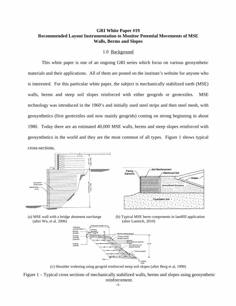
systems) and can be quite large without experiencing collapse; see Figure 4 for reinforced soil
slope movements of a 21 m (68 ft.) high slope in Alabama. Such basic surveying can also be
used if settlement plates are placed on the foundation soil and properly extended up through the
fill during construction. It should also be mentioned that GPS technology can be used with little
attention from personnel and is likewise felt to be sufficiently accurate for the purpose
considered herein.
(a) Theodolite for measuring lateral movement (b) Second-order automatic level for measuring (after Wild Heerbrugg, Inc.) vertical moment (after Kem Instruments, Inc.)
Figure 3 – Standard surveying instruments.
-5-
(a) Horizontal deflections
(b) Vertical Settlements
(c) Cumulative deflections
Figure 4 – Deflections at a MSE reinforced slope in Alabama (compl. GEI Consultants, Inc.).

-6-
2.2 Continuous Deformation Monitoring – There are several approaches to monitor deformation
in the reinforcement for use either directly or to convert to stress by means of a calibration curve.
They are classical strain gages or the more recent method using fiber optics. Electrical strain
gages have been applied to both geogrids and geotextiles usually by adhesive bonding or
mechanical attachment. Data of this type has been generated in both the laboratory and the field
and the literature is abundant in this regard. Using fiber optic measurements, glass fibers or
poly-optical fibers are applied to a geosynthetic by weaving or knitting. Within the fiber,
markers set at distances of decimeters to meters (inches to yards) are used. Elongation and
sometimes temperature between any two markers is measured. Specifically aimed at
geosynthetics, two systems are available. Fiber optical sensors are initially applied to the
geosynthetic itself or to an external carrier textile (see Figure 5); Schneider-Glöetzl, et al. (2010)
and Lostumbo and Artieres (2011). The systems can measure strain and monitor movement or
distortion of the structure. The accuracy of strain measurement is within 0.2% for the
GeoDetect® system. The strips are optimally placed before construction directly on the
foundation soil and then incrementally higher in the structure as it is being built. Using
directional drilling techniques it might even be possible to deploy the system after construction
and evidence of initial movement has been detected.
(a) GeoDetect® system components (b) Monitoring strains into a geotextile reinforced wall
Figure 5 – TenCate GeoDetect® system based on filter optic technology.

-7-
2.3 Slope Indicators – Slope indicators were initially developed in the 1970’s and have
progressed into field-ruggedized and dependable instruments for monitoring lateral
deformations. Their accuracy is excellent, i.e., 8-25 mm in 30 m (0.3-1.0 in. in 100 ft.). The
instrument is based on force balance accelerometers and is torpedo shaped with guide wheels. It
slides within a grooved casing which is inserted into an open borehole and then the annulus is
backfilled with a grout mix. Readings are incrementally taken and reported accordingly; see
Figure 6 in this regard.
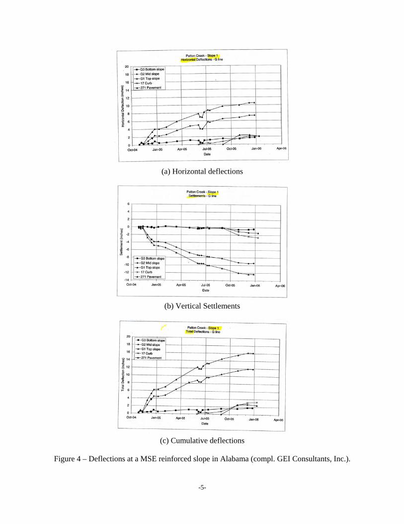
2.4 Piezometers – There are many different types of piezometers and they all basically measure
the change in pore water pressure (around the device itself) in a saturated soil mass. In regard to
MSE walls, berms and slopes they are appropriate within saturated fine-grained foundation soils
beneath the structure. A common type, which is quite reliable, is the vibrating wire piezometer
as shown in Figure 7. Piezometers are best utilized when placed before construction begins
under the future highest loaded portion of the wall, berm or slope, but have also been used post-
construction in the foundation soil in front of the toe of such structures. Readings measuring
pore water pressure over time and percent changes from previous readings are indicative of
effective stress changes. Decreases in excess pore water pressure indicate soil strength gains and
should be anticipated. Increases indicate improper drainage and are obviously causes of concern.

-8-
(a) Inclinometer system (after Slope (b) Principal of inclinometer operation Indicator Co., Seattle, WA)
(c) Typical plots of inclinometer data: (a) “change” plot and (b) “cumulative change” plot
(after Slope Indicator Company, Seattle, WA)
Figure 6 – Equipment concept and photo of slope indicators (after Dunnicliff, 1988).
-9-
(a) Pneumatic piezometer (after (b) Vibrating wire piezometer (after Thor International, Inc. Seattle, WA) Telemac, Asnières, France)
(c) Schematic of vibrating wire piezometer installed in a borehole
Figure 7 – Details of vibrating wire piezometers for pore water pressure monitoring (after Dunnicliff, 1988).

-10-
3.0 Instrumentation for MSE Walls and Slopes
Not only is a wealth of instrumentation available for monitoring MSE walls, berms and
slopes, the timing and location of their placement are also of importance. This section of the
white paper is separated into instrumentation deployment before and after construction.
3.1 Instrumentation Before Construction – Inasmuch as MSE structures are considered to be
flexible by their very nature, instrumentation might be considered at the outset for critical and/or
design challenging situations, e.g., extremely high structures, high surcharge loads, seismic or
dynamic loads, soft foundation soil, etc. By monitoring before construction one can quantify
any, and all, movements. Such measurements will serve to separate out movements during and
after construction. Without such base line or benchmark data it is almost impossible to tell if
movements are immediate or long-term.*
In this regard, the authors feel that surveying of the structure’s toe of slope should always
be performed. Monuments for elevations and lateral position should be offset by 1 to 2 m (3 to 6
ft.) from the toe of slope and set at distances 15-30 m (50-100 ft) apart. See Figure 8 in this
regard. A slope indicator(s) at the toe of the slope would also be appropriate particularly in front
of the highest section of the proposed wall, berm or slope location. If borings show saturated
foundation soil zones or layers, they should be the location of piezometer installations. Their
location should be beneath the areas which have the highest fill height. Deformation monitoring
along the foundation’s surface should also be considered and it can be installed by itself or along
with the first layer of reinforcing geosynthetic; recall Figure 5.
*Some acceptable movement should be anticipated during construction and NCMA suggests a two degree outward rotation from the intended facing batter is not unusual.

-11-
•
Legend
Surveying locations
Slope inclinometers
Deflection monitors
Piezometers
•
Geogrid Reinforcement
(a) Recommended layout for MSE walls and berms
•
(b) Recommended layout for MSE slopes
Figure 8 – Recommended layout of instrumentation to monitor potential movements before construction.
Proposed Footing
Proposed MSE Wall
Proposed Toe of Slope Proposed
MSE Slope
Deformation monitors

-12-
3.2 Instrumentation During and After Construction – Of course, surveying monuments can be
installed at any time during and after construction, but the later they are installed the more
potential construction induced movement will be lost. That said, “better late, than never” is
somewhat applicable. Clearly, the facing at midheight and the top of the wall or slope should
have survey monuments installed as soon as possible after final build-out; see Figure 9. As a
companion to the toe monuments, these higher monuments should be installed at 15 to 30 m (50
to 100 ft.) separation distances.
During construction, deformation monitoring can be installed at different wall or slope
heights, perhaps at the middle or quarter heights at the minimum as shown in Figure 5b.
Concern in this regard is over unintentional disturbance, thus the monuments must be carefully
considered and placed accordingly.
During or after the structure is completed to its full height, a slope indicator(s) should be
installed from the top, through the layers of reinforcement, and into the foundation soil; see
Figure 9. Note that drilling through the reinforcement layers is somewhat disconcerting and
precut holes may be considered, however, vertical alignment of holes is difficult to achieve.
Slope indicators can also be placed in front of the structure for foundation movement and/or
behind the reinforced soil zone to avoid the reinforcement but then they only capture movements
of the retained soil.
It might be noted that if deformation monitoring has not been installed during
construction, horizontal extensometers can be installed from the face of the wall or slope.
Dunnicliff (1988) gives examples of the different types of extensometers.
-13-
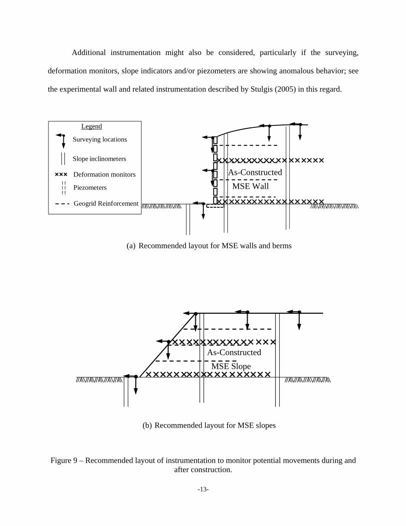
Additional instrumentation might also be considered, particularly if the surveying,
deformation monitors, slope indicators and/or piezometers are showing anomalous behavior; see
the experimental wall and related instrumentation described by Stulgis (2005) in this regard.
•
•
•• •Legend
Surveying locations
Slope inclinometers
Deflection monitors
Piezometers
•
Geogrid Reinforcement
(a) Recommended layout for MSE walls and berms
•
•
• • •
(b) Recommended layout for MSE slopes
Figure 9 – Recommended layout of instrumentation to monitor potential movements during and after construction.
As-Constructed
MSE Wall
As-Constructed
MSE Slope
Deformation monitors

-14-
Summary and Conclusion
In the Koerner and Koerner (2009) report of 82-failures (all were walls), twenty-three
(28%) of them were cases of excessive deformation. It is suggested that all of these deformation
cases should have had instrumentation monitoring of the type suggested herein as soon as the
initial anomalous feature(s) was observed. It is also suggested that such features are readily
observable, e.g., bulges at the toe of the structure, tension cracks at the end of the reinforcement,
separation of curb and pavement at the top of the structure, surface water drainage anomalies at
the top surface of the structure, leaning light posts, signage, and guard posts, etc. Without the
quantification provided by instrumentation monitoring the discussions entered into by the parties
involved after visual distortion is observed are extremely difficult due to their lack of
quantification. The situation can quickly become contentious in this regard.
In an attempt to mitigate such issues and come to a suggested course of action this white
paper has been prepared. In it, only select instrumentation devices and strategies are described.
There are many others which might be considered. Also, an indication of where the suggested
instruments should be located is offered. Here there are also many possible options.
One closing comment is that instrumentation should be considered before MSE wall,
berm or slope construction begins. Any feature considered atypical (very high systems, heavy
surcharge loads, seismic areas, adjacent water courses, etc.) or challenging (soft foundation soils,
poor quality backfill, limited construction oversight, drainage and other piping systems located
within the reinforced soil zone, etc.) should bring out the possibility, or necessity, of monitoring
instrumentation. Whenever an MSE wall, berm or slope is considered “critical”, the parties
involved should have such discussions as early in the process as possible and even before the
structure is constructed.

-15-
References
Bachus, R. and Griffin, L. M. (2010), “A Perspective on Mechanically Stabilized Earth Walls – Pushing the Limits or Pulling Us Down,” Proc. Earth Retention Conf. (ER 2010), ASCE, Seattle, WA, 13 pgs. Berg, R. R., Anderson, R. P., Rose, R. J. and Chouery-Curtis, V. E. (1990), “Reinforced Soil Highway Slopes,” Proc. 69th TRB Meeting, Washington, DC. Dunnicliff, J. (1988), Geotechnical Instrumentation for Monitoring Field Performance, J. Wiley & Sons, New York, 577 pgs. Elias, V., Christopher, B. R. and Berg, R. R. (2001), “Mechanically Stabilized Earth Walls and Reinforced Soil Slopes Design and Construction Guidelines,” FHWA-NHI-00-043, Washington, DC, 395 pgs. Koerner, R. M. and Koerner, G. R. (2009), “A Data Base of Analysis of Geosynthetic Reinforced Wall Failures,” GRI Report #38, Geosynthetic Institute, Folsom, PA, 195 pgs. Koerner, R. M. and Soong, T.-Y. (2001), “Geosynthetic Reinforced Segmental Retaining Walls,” Jour. Geotextiles and Geomembranes, Vol. 19, No. 6, pp. 359-386. Lostumbo, J. M. and Artieres, O. (2011), “Geosynthetic Enabled with Fiber Optic Sensors for MSE Bridge Abutment Supporting Shallow Bridge Abutment,” Proc. of Geo-Frontiers 2011, ASCE, Dallas, Texas, pp. 3497-3504. Luettich, S. (2010), Design and Construction of MSE Berms for Landfill Applications, Geosynthetic Report to Waste Management Inc., Acton, MA, October ~ 40 pgs. McKelvey, J. A. (2011), “Lessons Learned from Failures: The Wall of Shame,” Proc. of Geo-Frontiers 2011, ASCE, Dallas, Texas, pp. 3235-3244. National Concrete Masonry Association (NCMA), Design Manual for Segmental Retaining Walls, 3rd Edition (2009), Herndon, VA, 282 pgs. Schneider-Glöetzl, et al. (2010), “Geotechnical Monitoring of Construction Activities by Distributed Fiber Optic Sensors Embedded in Geotextiles,” Proc. European Workshop on Structural Health Monitoring, Sorrento, Italy, 8 pgs. Stulgis, R. P. (2005), “Full-Scale MSE Test Walls,” Proc. GRI-19 Conference, Las Vegas, NV, GEI Publ., Folsom, PA, pp. 166-171. Wu, J. T. H., Lee, K. Z. Z., Helwany, S. B. and Ketchart, K. (2006), “Design and Construction Guidelines for Geosynthetic Reinforced Soil Bridge Abutments with a Flexible Facing,” NCHRP Report 556, Washington, DC, 141 pgs.

-16-
Appendix – Possible Instruments for Monitoring Reinforced Soil Structures (after Elias, Christopher and Berg, 2001)
PARAMETERS POSSIBLE INSTRUMENTS Horizontal movements of face Visual observation
Surveying methods Horizontal control stations Tiltmeters
Vertical movements of overall structure Visual observation Surveying methods Benchmarks Tiltmeters
Local movements or deterioration of facing elements
Visual observation Crack gauges
Drainage behavior of backfill Visual observation at outflow points Open standpipe piezometers
Horizontal movements within overall structure Survey methods (e.g., transit) Horizontal control stations Probe extensometers Fixed embankment extensometers Inclinometers Tiltmeters
Vertical movements within overall structure Survey methods Benchmarks Probe extensometers Horizontal inclinometers Liquid level gauges
Performance of structure supported by reinforced soil
Numerous possible instruments (depends on details of structure)
Lateral earth pressure at the back of facing elements
Earth pressure cells Strain gauges at connections Load cells at connections
Stress distribution at base of structure Earth pressure cells

-17-
PARAMTERS (cont.) POSSIBLE INSTRUMENTS (cont.) Stress reinforcement Resistance strain gauges
Induction coil gauges Hydraulic strain gauges Vibrating wire strain gauges Multiple telltales
Stress distribution in reinforcement due to surcharge loads
Same instruments as for stress in reinforcement
Relationship between settlement and stress-strain distribution
Same instruments as for: vertical movements of surface of overall
structure vertical movements within mass of overall
structure stress in reinforcement Earth pressure cells
Stress relaxation in reinforcement Same instruments as for stress in reinforcement
Total stress within backfill and at back of reinforced wall section
Earth pressure cells
Pore pressure response below structures Open standpipe piezometers Pneumatic piezometers Vibrating wire piezometers
Temperature Ambient temperature record Thermocouples Thermistors Resistance temperature devices Frost gauges
Rainfall Rainfall gauges
Barometric pressure Barometric pressure gauges