reconstructing core transmission networks … core transmission networks using ... switches and...
TRANSCRIPT
Reconstructing Core TransmissionNetworks Using ATM and DWDM
05-57bRev: 09/00

Table of Contents
1. Executive Summary 2
2. The Evolving Transmission Infrastructure 3
3. Today’s Reliable SONET/SDH TDM Networks 5
3.1 How SONET/SDH Works 5
3.2 Provisioning Private-line Services on the SONET/SDH TDM Network 6
3.3 Accommodating Data Services on the SONET/SDH TDM Network 7
3.3.1 The Traditional Overlay Data Network Approach 7
3.3.2 Private-line Services for Data 8
3.3.3 Access Solutions for Offloading Data Services from the Voice Network 9
4. Meeting the Data-centric Service Demands of Tomorrow with Multiservice Networks 10
5. ATM—The New Approach to Multiservice Networking 11
5.1 The Major Carriers’ ATM Infrastructure Plans 115.2 Advantages of an ATM Infrastructure Approach 12
6. The Lucent Solution 14
6.1 The Lucent GX 550 Multiservice WAN Switch 15
6.1.1 Integrating the DCS Functions 15
6.1.2 Integrating SONET/SDH ADM Functions 16
6.1.3 Integrating End-to-End Provisioning and Maintenance Functions 16
6.2 TDM-to-ATM Circuit Adaptation 16
6.3 A New Transmission Network 17
6.4 A Next-generation Network 18
7. Provisioning and Maintenance Cost Model—Five-Node Network 197.1 Service Provisioning Cost Savings – Private Line and Data 20
7.2 Equipment Maintenance Cost Savings 20
7.3 Other Cost Savings 21
Appendix A: Five-Node Cost Model—Service Provisioning and Maintenance 21
Network Assumptions 22
Service Assumptions 22
Appendix B: Packet Switching vs. Circuit Switching 25
1
Executive SummarySparked by advances in technology and the worldwide explosion of data applications, innovativecompetitive carriers are now implementing the next major transmission network construction—the incorporation of Multiservice Wide Area Network (WAN) switches and Dense Wave DivisionMultiplexing (DWDM) facilities into the network.
The Lucent Multiservice WAN solutions include the GX 550, CBX 500™ and B-STDX 9000™Multiservice WAN switches, IP Navigator™ MPLS, and NavisCore™ and NavisXtend™ networkmanagement control software that provides end-to-end network management. IP NavigatorMPLS allows service providers to manage and provision IP services on the ATM backbone,which adds IP Layer 3 routing to the Lucent WAN switches and “Absolute” QoS. This multiser-vice system allows service providers to deliver and manage all services—ATM, frame relay andIP—from a single ATM core network and provides a manageable, scalable, carrier-class networkinfrastructure specifically designed for service providers.
This new transmission network design has all the reliability, manageability, vendor interoper-ability and capacity of leading-edge Synchronous Optical Network/Synchronous DigitalHierarchy (SONET/SDH) Time Division Multiplexed (TDM) networks—with the efficiency andmultiservice capability of ATM technology.
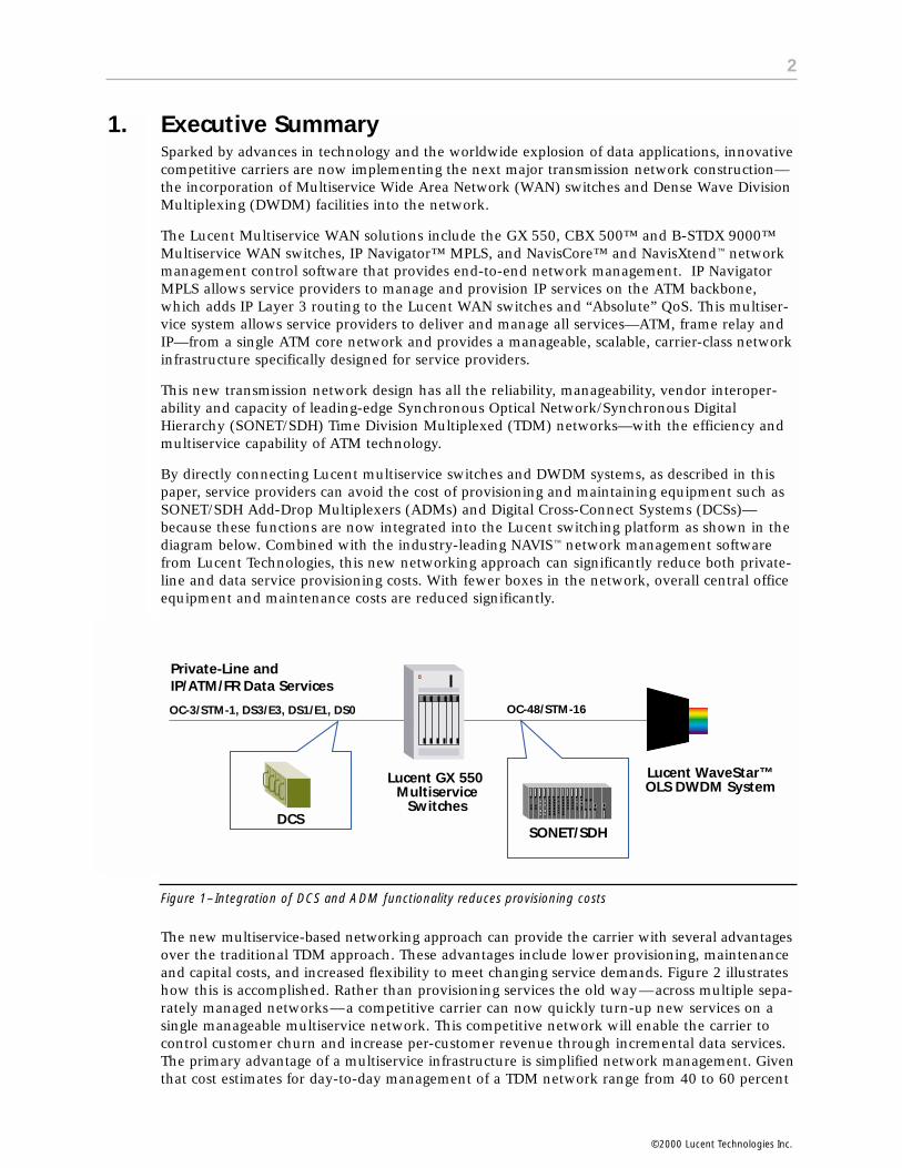
By directly connecting Lucent multiservice switches and DWDM systems, as described in thispaper, service providers can avoid the cost of provisioning and maintaining equipment such asSONET/SDH Add-Drop Multiplexers (ADMs) and Digital Cross-Connect Systems (DCSs)—because these functions are now integrated into the Lucent switching platform as shown in thediagram below. Combined with the industry-leading NAVIS™ network management softwarefrom Lucent Technologies, this new networking approach can significantly reduce both private-line and data service provisioning costs. With fewer boxes in the network, overall central officeequipment and maintenance costs are reduced significantly.
Figure 1– Integration of DCS and ADM functionality reduces provisioning costs
The new multiservice-based networking approach can provide the carrier with several advantagesover the traditional TDM approach. These advantages include lower provisioning, maintenanceand capital costs, and increased flexibility to meet changing service demands. Figure 2 illustrateshow this is accomplished. Rather than provisioning services the old way—across multiple sepa-rately managed networks—a competitive carrier can now quickly turn-up new services on asingle manageable multiservice network. This competitive network will enable the carrier tocontrol customer churn and increase per-customer revenue through incremental data services.The primary advantage of a multiservice infrastructure is simplified network management. Giventhat cost estimates for day-to-day management of a TDM network range from 40 to 60 percent
2
DCSSONET/SDH
Lucent GX 550 Multiservice
Switches
Lucent WaveStar™OLS DWDM System
Private-Line andIP/ATM/FR Data Services
OC-3/STM-1, DS3/E3, DS1/E1, DS0 OC-48/STM-16
1.
©2000 Lucent Technologies Inc.

of overall service delivery cost, and that today’s network elements have overlapping networkfunctions, there is considerable opportunity for cost savings.
This paper concludes with a five-node network model used to quantify the service provisioningand maintenance cost savings made possible by this new multiservice network. The networkcost model presented supports recent carrier claims that the multiservice network approach can achieve significant cost savings over traditional networks. The model concludes that provi-sioning intervals can be ten times faster and that 80 percent maintenance costs savings can berealized using this new integrated approach.
Figure 2–Traditional Networks vs. New ATM-Approach
The justifications for reconstructing core transmission networks with ATM and DWDM include:
• Equipment Cost: Reduced cost of the transmission infrastructure, including capital equipment costs as well as operations and maintenance costs.
• Ease of Provisioning: Reduced cost and increased speed and flexibility of multiservice provisioning.
• Capacity: Traditional transmission and switching networks built for voice services cannot continue to accommodate exponential data services growth. However, new ATM-based transmission infrastructures can provide the scalable capacity required for tomorrow’s data service demands as well as traditional private-line services.
• Reliability: Advances in ATM-based transmission infrastructures make them equally as reliable as today’s TDM-based telephone network. Lucent ATM switches have SONET/SDH-compliant automatic protection switching (APS) capabilities, and the entire ATM network has inherent intelligent traffic re-routing capability.
• Competition: Competitive carriers are building new multiservice transmission infrastructures based on ATM and DWDM. These new carriers are changing the rules of the game by offering high-speed data services at consistently lower costs than incumbent legacy network operators
The Evolving Transmission InfrastructureHistory shows that transmission networks have been reconstructed on a regular basis. Over thepast 80 years, transmission networks have steadily evolved to become higher in capacity, moreaffordable, standards-based, more reliable, and easier to operate, maintain, and provision. Figure 3shows the major milestones in transmission network development and their associated improvements.
2.
3
©2000 Lucent Technologies Inc.

Figure 3–Transmission Evolution Timeline
In 1915, the first transcontinental phone call was made from New York to San Francisco over anall-analog network of copper cables, amplifiers and switchboards. Since then, breakthroughs intransmission media technology have served as the primary compelling events for major network re-builds. In 1936, the public switched telephone network’s (PSTN’s) first coaxial cable route (NewYork to Philadelphia) allowed multiplexing of many analog voice signals on a single cable, usingthe L-Carrier Hierarchy. In 1947, the first microwave route allowed a cheaper alternative to longcoaxial cable routes. In 1962, the first telecommunications satellite links proved cheaper thanundersea cable routes. And in the early 1980s, fiber-optic cables introduced the extra bandwidthnecessary to support the first major reconstruction—from analog to digital transmission networks.
Transmission networks have grown up around voice services. The early L-Carrier Hierarchyprotocol, consisting of multiplexed analog voice signals over coaxial cable, was eventuallyreplaced by the Plesiochronous Digital Hierarchy (PDH) protocol made up of TDM digitizedvoice signals (i.e. DS1, E1, DS3, E3, etc.). These digital signals were transmitted over copper and coaxial cables until the introduction of fiber-optic cables. The range and reliability of digitalfiber-optic transmission systems forced the complete reconstruction of analog transmission net-works, where carriers replaced all analog coaxial and microwave routes with point-to-pointdigital fiber-optic facilities that are still used today. With the advent of reliable digital facilitiescame frame relay, which was adopted as a faster alternative to the leading X.25 data communi-cations protocol and designed to take advantage of reliable digital transmission networks.
Following frame relay, innovative proprietary PDH Add/Drop ring functionality was added tothe digital fiber networks, increasing reliability, topology options and provisioning ease. In1990, the SONET/SDH standard sparked the next reconstruction of transmission networks,replacing the proprietary PDH self-healing networks with standard SONET/SDH infrastructures.SONET/SDH networks, with their 50 milliseconds self-healing capability, have since remainedthe most reliable networks available. Today, fiber-optic transmission facilities and the reliabilityof SONET/SDH topologies are the mainstay of transmission networks. These technologies havemet the industry’s long-sought objectives of standard, high-capacity, easy-to-provision andultra-reliable (99.999 percent) transmission for voice and private (or leased) line services. Thisreport focuses on the next reconstruction of transmission networks—the integration of ATMtechnology into the infrastructure—that is currently underway.
4
First transcontinental phone call over analog/copper network
1915
Reconstruction on #1Analog L-Carrier shift toDigital Hierarchy
Reconstruction on #3Integration of ATM into transmissionand switching networks
Reconstruction #2Proprietary digital PDH fiber networksreplaced by Standard SONET/SDH
First coaxial cable route in service from NY to DC
First microwave routes in service
First telecommunications satellites
Beginning acceptance ofSONET/SDH standards
Proprietary PDH Fiber Optic Networks
Beginning of Fiber Optic Cable Deployments
New carrier networksbased on ATM,DWDM, and IP
1936 1947 1962 1980 1990 TODAY 2000+
©2000 Lucent Technologies Inc.

Today’s Reliable SONET/SDH TDM NetworksAs part of the ongoing network evolution, SONET/SDH networks have replaced proprietary PDH fiber-optic networks. This reconstruction is attributed to factors including: (1) internationalacceptance of the SONET/SDH standard, (2) the promise of vendor interoperability and lowerequipment costs, (3) the self-healing capability of SONET/SDH, (4) the high capacity interfacesof SONET/SDH and (5) the capability for SONET/SDH overhead channels to support enhancedoperations, administration, maintenance and provisioning (OAM&P) functions. With these features, the SONET/SDH networks of today, comprising nearly 100 percent of local andinterexchange carrier transmission facilities1, have become the new benchmark for fiber-optic network quality.
As shown in Figure 4 below, SONET/SDH networks are primarily used to provision dedicatedDS1, E1, DS3, E3, OC-3, STM-1, OC-12 and STM-4 circuits with each circuit having a redun-dant path across the network. This enables all other traditional transmission and switchingequipment to connect to the SONET/SDH network for reliable transport.
Figure 4–Today’s Advanced SONET/SDH Infrastructure
3.1 How SONET/SDH Works
The SONET/SDH standard is essentially a framing format and a series of interface specificationsthat answer the question, “What to put on optical wavelengths?” While SONET/SDH does notprovide switching or routing, it does provide an ultra-reliable means for provisioning point-to-point digital bandwidth pipes. Unlike PDH frames, the SONET/SDH frame structure has plentyof overhead bytes. This overhead is used primarily for maintenance, provisioning and advancedself-healing network functions. When SONET/SDH network elements are connected in a net-work, the overhead channels can be extended throughout the carrier infrastructure across network elements to allow end-to-end provisioning and maintenance of circuits. In the mostadvanced deployments, provisioning and maintenance information is communicated betweenSONET/SDH network elements by means of the 512 Kbps digital control channel (DCC), whichis part of the overhead. The SONET/SDH standards dictate how each overhead byte must beused to support advanced networking functions such as ring protection and multi-vendor mid-span meets. The SONET/SDH software performs these functions.
3.
POTS to Home
Central Office #1Lucent DACS II
DCS56/64 Kbps
Non-SwitchedData Service
DS1/3, E1/3
Lucent 4/5ESSVoice Switch
ISDN or 56/64 Kbpsto Home or Business
Lucent SONET/SDH Network Element Managers
SONET IOFTransport
OC-48/192,STM-16/64
RingDS3, E3,OC-3/12,STM-1/4Circuits
SONETAccess
OC-3/12STM-1/4
Ring
SONET AccessOC-3/12, STM-1/4 Ring
DS3, E3, OC-3/12, STM-1/4Private-Line Circuits
Lucent FT-2000& WaveStar™
SONET/SDH ADM
Lucent DDM-2000& WaveStar™
SONET/SDH ADM Lucent FT-2000& WaveStar™
SONET/SDH ADM
Lucent "DACS"Family DCS
NGDLC
Frame RelayATM, xDSLVoice-ISDNDS1/E1
IXC
CentralOffice #2
CentralOffice #3
5
1 Goralski, Walter J., SONET/SDH—A Guide to Synchronous Optical Networks, 1997©2000 Lucent Technologies Inc.
3.2 Provisioning Private-line Services on the SONET/SDH TDM Network
As shown in Figure 4, today’s SONET/SDH facilities are well integrated into the PSTN. MostCentral Office equipment now comes equipped with SONET/SDH interfaces that allow the inte-gration of voice switching, Inter-Office Facilities (IOF) and access transmission networks. Asdepicted, advanced Digital Cross-Connect Systems (DCS) now have SONET/SDH ring interfacesallowing direct connection to Next-Generation Digital Loop Carrier (NGDLC) systems,SONET/SDH transport and access rings. These SONET/SDH interconnections allow switching,transmission and NGDLCs to operate as one integrated network, where voice circuits and Private-line data circuits can be provisioned and monitored from end-to-end. This networkintegration has streamlined the maintenance and provisioning of these services—meaning significant cost savings for carriers.
Using this integrated SONET/SDH network, private-line services are easy to provision. The easiest to provision is a non-switched 56/64 Kbps circuit between two points. These 56/64 Kbpscircuits are provisioned within the SONET/SDH infrastructure using any combination of copperaccess loops, 3/1/0 DCS and Class 4/5 switches with “nailed-up” connections. Another commonprivate-line service is a dedicated T1/E1, requiring any combination of copper (or fiber) accessloops, SONET/SDH access and transport ADMs, Digital Subscriber Line (DSL) multi-plexers and the 3/1 DCS. Finally, dedicated T3/E3 private-line services are also offered on the SONET/SDH TDM network, requiring fiber access loops, an OC-3/STM-1 access node at the customerpremises, as well as SONET/SDH transport and 3/1 DCS resources in the Central Office.
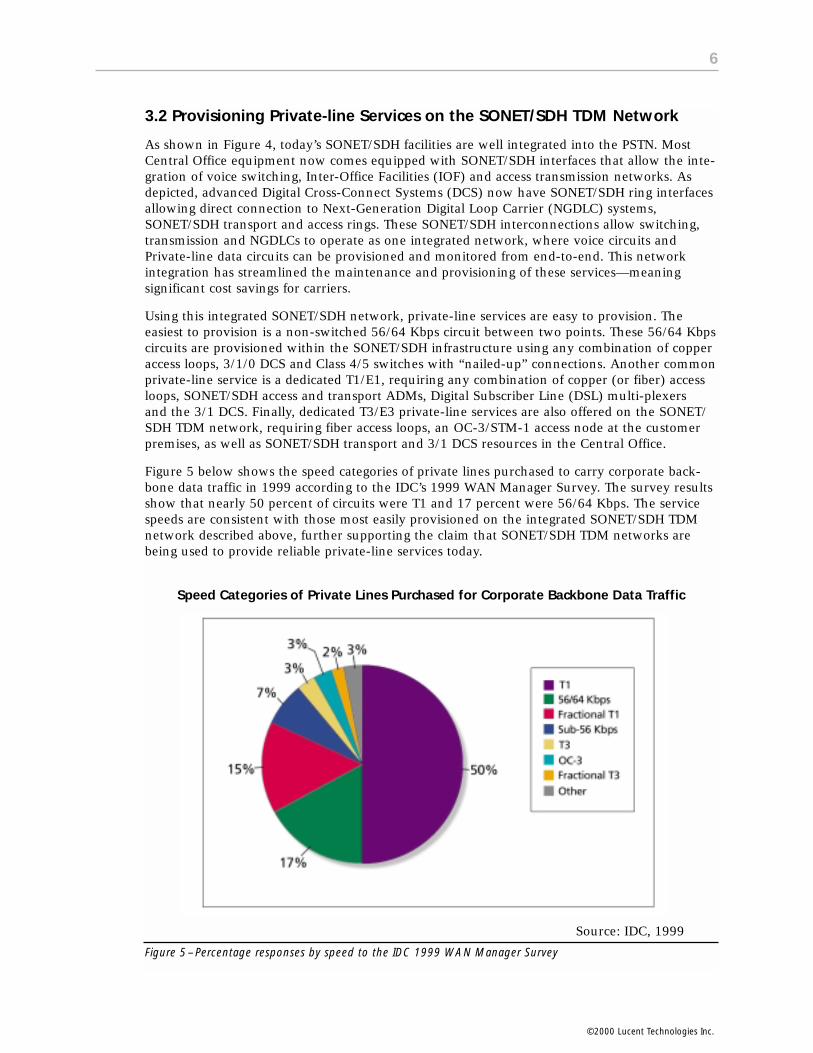
Figure 5 below shows the speed categories of private lines purchased to carry corporate back-bone data traffic in 1999 according to the IDC’s 1999 WAN Manager Survey. The survey resultsshow that nearly 50 percent of circuits were T1 and 17 percent were 56/64 Kbps. The servicespeeds are consistent with those most easily provisioned on the integrated SONET/SDH TDMnetwork described above, further supporting the claim that SONET/SDH TDM networks arebeing used to provide reliable private-line services today.
Source: IDC, 1999
Figure 5–Percentage responses by speed to the IDC 1999 WAN Manager Survey
Speed Categories of Private Lines Purchased for Corporate Backbone Data Traffic
6
©2000 Lucent Technologies Inc.
3.3 Accommodating Data Services on the SONET/SDH TDM Network
The traditional approach for constructing transmission networks was developed and refinedwhen voice was the predominant form of traffic. In order to transport the growing amount ofdata, data traffic was made to look like voice traffic and to fit within the existing networkmodel.
Several popular solutions for accommodating data services on today’s SONET/SDH TDM net-works are described below. These solutions illustrate how the current combination of TDM pri-vate-line circuits and overlay packet data networks are used to accommodate today’s WAN dataservice demands.
3.3.1 The Traditional Overlay Data Network Approach
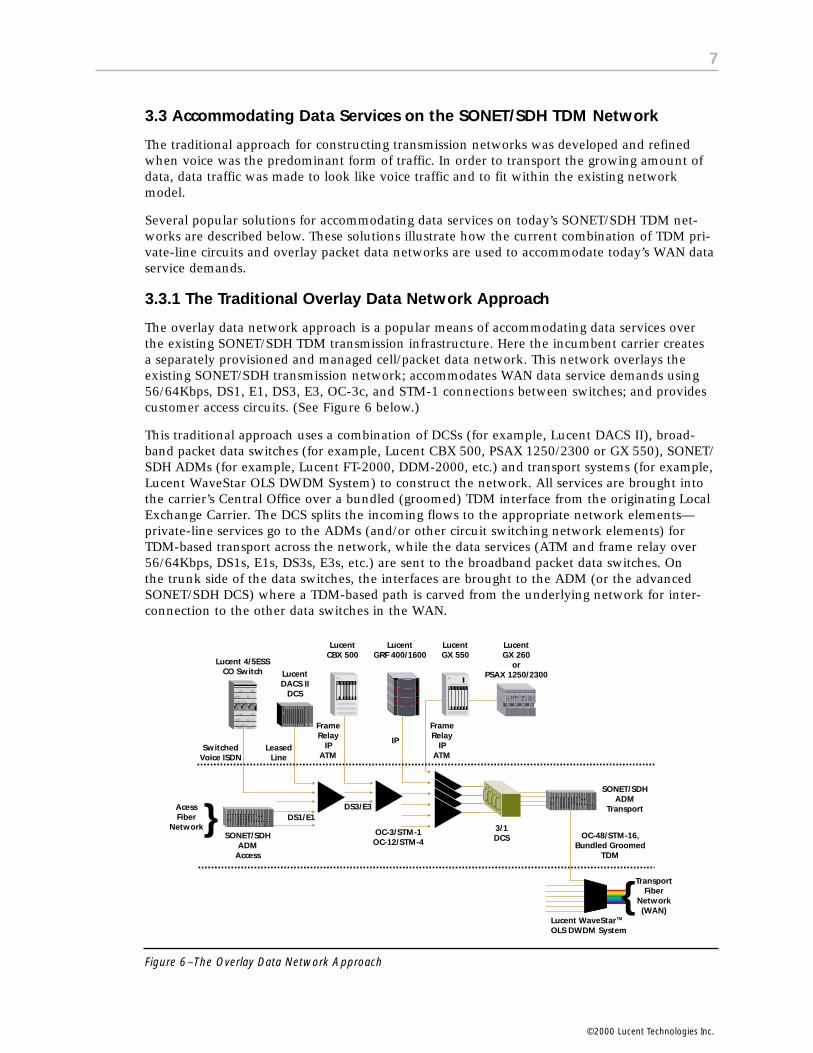
The overlay data network approach is a popular means of accommodating data services overthe existing SONET/SDH TDM transmission infrastructure. Here the incumbent carrier creates a separately provisioned and managed cell/packet data network. This network overlays theexisting SONET/SDH transmission network; accommodates WAN data service demands using56/64Kbps, DS1, E1, DS3, E3, OC-3c, and STM-1 connections between switches; and providescustomer access circuits. (See Figure 6 below.)
This traditional approach uses a combination of DCSs (for example, Lucent DACS II), broad-band packet data switches (for example, Lucent CBX 500, PSAX 1250/2300 or GX 550), SONET/SDH ADMs (for example, Lucent FT-2000, DDM-2000, etc.) and transport systems (for example,Lucent WaveStar OLS DWDM System) to construct the network. All services are brought intothe carrier’s Central Office over a bundled (groomed) TDM interface from the originating LocalExchange Carrier. The DCS splits the incoming flows to the appropriate network elements—private-line services go to the ADMs (and/or other circuit switching network elements) forTDM-based transport across the network, while the data services (ATM and frame relay over56/64Kbps, DS1s, E1s, DS3s, E3s, etc.) are sent to the broadband packet data switches. On the trunk side of the data switches, the interfaces are brought to the ADM (or the advancedSONET/SDH DCS) where a TDM-based path is carved from the underlying network for inter-connection to the other data switches in the WAN.
Figure 6–The Overlay Data Network Approach
LeasedLine
SwitchedVoice ISDN
{Transport
FiberNetwork(WAN)
DS1/E1{AcessFiber
Network
FrameRelay
IPATM
LucentDACS II
DCS
Lucent 4/5ESSCO Switch
LucentCBX 500
LucentGRF 400/1600
LucentGX 550
LucentGX 260
orPSAX 1250/2300
FrameRelay
IPATM
IP
DS3/E3
OC-3/STM-1OC-12/STM-4
3/1DCS
SONET/SDHADM
Transport
OC-48/STM-16,Bundled Groomed
TDM
Lucent WaveStarOLS DWDM System
TM
SONET/SDHADM
Access
7
©2000 Lucent Technologies Inc.

While this overlay data network solution offers all the benefits of an end-to-end packet-switched network (see Appendix B), it must be managed separately, and it must use availableTDM transmission facilities that connect at the pre-determined rates of 56/64 Kbps, DS1, E1,DS3, E3, OC-3 and STM-1.
3.3.2 Private-line Services for Data
As shown below, a significant portion of the respondents to the 1999 IDC WAN Manager Surveycontinue to use private-line (TDM non-packetized) services for corporate backbone data traffic.
Source: IDC 1999
Figure 7–Mean percentages of corporate backbone data traffic by service type
Solutions 1 and 2 below are pure adaptations of the voice-centric TDM network used to accommodate business’s private-line connectivity needs. Although both are viable solutions that satisfy service needs today, they are quickly using up spare voice network capacity—each private “line” occupies a dedicated 64 Kbps or T1/E1 circuit 24 hours per day, 365 days per year. Additionally, once these services are provisioned, the carrier has limited flexibility to change the service offering upon customer request.
SOLUTION 1: Using both NGDLC and Class 5 voice switches to provision non-switched private-line services. All Class 5 switches and NGDLC systems are capable of provisioning 56/64 Kbps “special services” (non-POTS services) in this manner. Depending on the capability of the NGDLC to groom special services off of the digital switching network, this solution may require nailed-up connections through the voice switch—an inefficient use of voice switch capacity.
SOLUTION 2: Using the Central Office 3/1/0 DCS to provision non-switched private-line services without using the Class 4/5 switches at all. In this solution, each Central Office DCS is connected directly to the copper and SONET/SDH fiber-optic access networks as well as to SONET/SDH Inter-Office Facilities (IOF), thus allowing end-to-end provisioning of dedicated private-line 64 Kbps and DS1/E1circuits between business locations.
8
PrivateLines
FrameRelay
ISDN IP-basedVPN
ATM X.25 VSAT SMDS Other
©2000 Lucent Technologies Inc.

3.3.3 Access Solutions for Offloading Data Services from the Voice Network
Dial-up data applications are used heavily around the world for residential and business appli-cations. The most noticeable evidence of this fact is the “all circuits are busy” message heardduring peak hours of dial-up data network use. Two emerging solutions for offloading dial-updata calls from the switched voice network are described below.
SOLUTION 1: Using advanced dial-up data “access concentrator” solutions that replace the Class 5 voice switch function for all dial-up data calls. In this solution,the advanced data access concentrators connect to the PSTN via inter-machine trunks (IMTs) and SS7 signaling “a-links,” thus creating a lower-cost, data-centric alternative for terminating the increasing long-hold-time, dial-up data traffic. These advanced access concentrators convert the PSTN traffic to a pure data communica-tions format, compatible with data-centric networks of tomorrow (see “The CLEC Opportunity in Managed Ports Services,” Lucent White Paper, 1998).
SOLUTION 2: Converting access lines from POTS and ISDN to xDSL. This solution creates an access network that does not terminate directly onto Class 5 Central Office switches but terminates onto advanced data-centric ATM switches that can connect various voice/data services to appropriate transmission or switching facilities.
Data Demand—Strong Continued Growth
The growth of the Internet continues at an unprecedented rate. According to a survey byCommerceNet/Nielsen Media Research, nearly one in every four adults in the United Statesand Canada is online. A number of sources have cited that this number has reached one inevery three Americans. International Data Corporation estimates that there were 160 millionWeb users worldwide at the end of 1998. Killen & Associates projects that almost 400 millionusers will have access to the Internet by the year 2002. While estimates vary among researchfirms, one forecast is quite consistent—the forecast for strong continued growth of the Internetand data services.
Source: DataQuest 1999
Figure 8 –The Overlay Data Network Approach
0
100
200
300
400
500
1997 1998 1999 2000 2001 2002
Rel
ativ
e C
apac
ity
(Mill
ion
s o
f C
han
nel
s)
YearVoice Data
9
©2000 Lucent Technologies Inc.

Data Services Growth – Outpacing Voice Services
While voice communications is a big business, it is a relatively static one. Lack of differentiatedservices force carriers to compete with each other by cutting prices and/or adding extra servicessuch as voice mail at no charge. As shown in Figure 8, DataQuest predicts that data traffic willsurpass voice in the year 2000. Gasman Research conservatively estimates that data serviceswill surpass voice services within the next six or seven years in the local access market andbecome a $100B dollar market in ten years. The message is clear—the WAN market is headedtoward a data-centric service mix.
Meeting the Data-centric Service Demands of Tomorrow with Multiservice NetworksWhile today’s SONET/SDH TDM networks can accommodate data and private-line services, these networks may soon realize their limitations when faced with competition from data-centric multiservice networks. Multiservice networks, which are scalable and optimized fordata, will have the ability to handle tomorrow’s data-centric service mix including private-lineservices (voice and video). On the other hand, legacy TDM networks will be challenged toaccommodate increasing data service demands through their legacy approach. Figure 9 belowillustrates the trend toward meeting future service demands with multiservice networks.
Figure 9– Meeting Future Service Demands with Multiservice Networks
The passage of the Telecommunications Act of 1996, combined with explosive growth of theInternet and related data services, has created a new competitive market requiring efficientmultiservice carrier networks. Now, more than ever, carriers are searching for better ways toaccommodate data and private-line services on a common network infrastructure.
Just as frame relay technology has allowed carriers to offer T1/E1 data-connectivity service at one-third the cost of private-line T1/E1 service (see “New Data Carrier,” TeleChoice, 1997), thecarriers who succeed in building new multiservice transmission infrastructures will change therules of the game by offering higher-speed services consistently below competitors’ prices.
0
50
100
150
200
250
ConvergedData OnlyVoice Only
1991 1993 1995 1997 1999 2001 2003 2005 2007 2009
Year
$ in
Bill
ion
s
4.
Source: NPRG Research March 1998
10
Total Revenues from Convergent Voice and Data Markets
©2000 Lucent Technologies Inc.

As the worldwide demand for high-speed data services continues to climb and data becomesincreasingly critical to everyday business operations, incumbent carriers risk losing loyal busi-ness customers whose pent-up demand for high-speed data services cannot be met by legacytransmission infrastructures. These previously loyal business customers will switch to serviceproviders who can satisfy their need for high-speed, low-cost data service. In this environment,competitive carriers must play by the new rules, offering cost-competitive data, voice and videoservices on multiservice networks.
ATM—The New Approach to Multiservice NetworkingSince data traffic is inherently variable, transporting this type of traffic over an underlying TDMnetwork is inefficient. And, as the amount of data traffic continues to grow exponentially comparedto voice/private-line-based services, the inefficiencies of a TDM infrastructure are exacerbated.
A new approach, based on an ATM infrastructure that can take advantage of the statistical nature ofdata traffic as well as the constant rate of private-line traffic, provides a more bandwidth-efficientsolution. Additionally, the service provider can use the sophisticated networking features of ATM-based switches as a new source of premium, carrier-differentiating service offerings.
Just as SONET/SDH is a worldwide-ratified standard for “what to put on optical wavelengths,”ATM is a worldwide-ratified standard for “what to put into SONET/SDH frames” when buildingreliable multiservice networks. The advanced ATM switches deployed today are equipped withSONET/SDH interfaces ranging from OC-3/STM-1 to OC-48/STM-16 and support Quality ofService (QoS) levels up to the highest ATM QoS option—“TDM circuit emulation (CE)” ser-vices. And, the advent of ATM technology’s high-speed interfaces introduces the opportunityfor tighter integration of the core data-switching function into the transmission access andtransport networks.
5.1 The Major Carriers’ ATM Infrastructure Plans
With new data service demands changing the rules of the game, today’s network planners realizethat any new equipment installations must be capable of handling both voice and data services.This new planning rule has gained popularity for many reasons including the following:
• Although data service growth is outpacing that of voice services, incumbent carriers as well as new competitive carriers realize that voice and private-line services still account for the majority of revenues and network bandwidth consumption today.
• Today’s users are accustomed to 99.999 percent voice network reliability, and any network “improvements” must maintain this performance.
• Working within the constraints of their existing networks, incumbent carriers are quickly using up voice network capacity to meet the growing demand for data services.
• Incumbent carriers are watching closely as start-up competitive carriers build new networks that are better suited to meet tomorrow’s data service demand.
Although several technologies have the promise of handling tomorrow’s data-centric service mix,robust ATM switching infrastructures, backed by ATM standards, have become the solution ofchoice for multiservice backbone networks. Thus far, all incumbent and most competitive carri-ers have invested in core ATM infrastructures. Using these infrastructures, carriers plan to offerboth traditional voice services and emerging data services on one efficient infrastructure that iseasy to provision and manage. Some examples of new ATM networks are: Williams Communications’New Public Network based on ATM and DWDM, Bell Atlantic’s Long Distance Data Network,the top-rated SAVIS’s ATM Internet Backbone and Digital Broadcast Networks’ ATM infrastruc-ture. And, carriers in both Europe and Asia are building new networks of this type today.
5.
11
©2000 Lucent Technologies Inc.

5.2 Advantages of an ATM Infrastructure Approach
As attested by network deployments from leading carriers, ATM-based transmission infrastruc-tures meet the requirements for current and future networks by preserving today’s networkreliability while supporting tomorrow’s data-centric service mix in a standard, scalable networkinfrastructure. Forward-looking carriers realize the benefits of provisioning multiple servicesusing a single integrated ATM network.
The primary advantage of an ATM infrastructure is simplified network management and provi-sioning. With cost estimates for day-to-day management of a network ranging from 40 to 60percent of overall service delivery cost, streamlined network management offers the potentialfor considerable operational cost savings. From the perspective of capital equipment costs, thereis less equipment to buy. And from a revenue perspective, ATM switches provide a rich set ofsoftware-based networking features that allow the service provider to offer services that have not been possible before, enabling a whole new stream of revenue.
Brief descriptions of the capabilities and advantages of an ATM-based infrastructure follow.
• Lowered Operational and Capital Costs
Basically, with an ATM infrastructure there are less “boxes” to buy and manage. This offers considerable savings in sparing, support and training for a decreased amount of network-based equipment. And, there are other operational savings that are realized as a result of the features supported by ATM switches, such as automatic provisioning and reconfiguration, built-in test capabilities, etc. (These features are described below.) Finally, by providing more efficient bandwidth management, an ATM-based infrastructure minimizes the actual amount of wide-area bandwidth.
• Effective Bandwidth Management
In a TDM-based approach, time slots are dedicated for connections regardless of whether information is actually being sent. In fact, for a multiservice network, the underlying net-work is physically subdivided into multiple networks, one for each service (for example, voice, private line, data, etc.). An ATM-based infrastructure enables a much more efficient use of the transmission network. Statistical multiplexing of data traffic can occur side-by-side with the transport of delay- and loss-sensitive traffic. Within the network, bandwidth can be subdivided with hard boundaries, soft boundaries or no boundaries. And, as the ATM switchesare non-work-conserving, bandwidth is never wasted and data is always sent.
For applications such as DS3/E3 video private-line transport, additional bandwidth savings are possible by recognizing the presence/absence of video information. If there is no video information to be sent, rather than consuming ATM bandwidth by sending a null signal, no data is sent—freeing up bandwidth for other applications. Future voice applications will employ similar efficiencies by not sending idle conversation segments and by using voice compression—again, freeing up additional bandwidth for other applications.
• Ease of Provisioning
Provisioning across the ATM infrastructure is also simplified considerably. For initial network service, the network operator selects the ingress and egress points of the network, and the ATMswitches find the best path across the network, automatically provisioning any necessary interworking functionality. This is referred to as “Point, Click, Done.” As the amount of connections grow, the provisioning of connections across the network can be automated by connecting ordering systems directly to a provisioning server through a standards-based Applications Programming Interface (API).
12
©2000 Lucent Technologies Inc.

In traditional TDM networks, complex procedures are required for adding or changing services, and each provisioned circuit requires endless documentation. With an ATM-based transmission infrastructure, circuit provisioning, bandwidth changes and monitoring are simplified through the use of standard packet network management methods.
• High Availability
Network resiliency is achieved through a combination of ATM-switch capabilities. These capabilities include loss-less fabric switchover for hardware failures, Automatic Protection Switching (APS) for protection against physical line card and fiber failures, and VC re-routing at a rate of thousands of connections per second if facility recovery does not occur. And, reconfiguration is automatic because the switches can intelligently determine the new path based on current network conditions — an intelligent DCS function.
• Sophisticated Test Capabilities
ATM switches provide an extensive set of testing capabilities for verifying and sectionalizing troubles. For example, external testers are not needed because PRBS generators are built into the line cards. Additionally, the ATM switches provide monitoring and testing capabilities at all layers (Layer 1, Layer 2, Layer 3, etc.). For example, at the physical layer, SONET/SDH performance monitoring is supported. At the ATM level, Network Traffic Management, as well as Network Data Collection, provides the network operator with real-time statistics on congestion level and per-port and circuit measurements. Finally, the inherent multicast capability of an ATM switching system allows a connection to be copied and split off to an egress point for further examination/analysis by testing equipment.
• Premium Service Offerings
ATM switches provide a rich set of networking features that are not possible with TDM-basedequipment. Using these capabilities, a carrier can demonstrate differentiation as well as offer premium services. Examples of these services include guaranteed performance, Virtual PrivateNetworks, prioritized re-routing, adjustable statistical multiplexing levels, security screening, closed user groups, user circuit reconfiguration, customizable traffic reports and customer network management, among others.
Today, ATM supports voice, video, cellular, IP, frame relay, private line and more. In the future, all data services, as well as many voice and video service offerings will be based on IP,and the ATM network’s guaranteed QoS capability will support the various QoS needs of these future services. For example, an extensive voice-over-IP (VoIP) service offering (or broadcast video application) that would not perform well under “best effort” conditions will have guaranteed quality if provisioned over an ATM-based infrastructure.
• Support of Legacy Networks
With the variety of interfaces available on ATM equipment today, all legacy data and voice/video services can be supported. Advanced ATM switches have DS1, E1, DS3 and E3 interfaces as well as standard data communications interfaces such as 10/100 Mbps Ethernet, IP, frame relay and X.25.
• Lower Installation and Maintenance Costs
Placing the ATM switch at the core of the multiservice network will notably reduce the amount of equipment required in the Central Office. This enables lower equipment instal-lation costs, fewer physical connections to maintain, and integrated network management and provisioning capabilities across the network. And, by reducing the amount of equipment, overhead expenses like floor space, power, etc., are reduced. All of these improvements will result in infrastructure cost savings.
13
©2000 Lucent Technologies Inc.

The Lucent SolutionIn response to the exponential growth of data service demand, particularly IP traffic demand,service providers can now build data switching networks that rival the speed, reliability andmultiservice capability of legacy TDM transmission networks. Rather than using the traditionallayered architecture approach of a switching, transmission and optical network where multiplenetworks are managed and provisioned separately (as shown in Figure 10 below), serviceproviders can now leverage advances in multiservice ATM switching technology where thefunctionality of legacy transmission equipment (SONET/SDH ADMs and DCSs) resides directlyin the switching network.
Figure 10–The Traditional Layered Network Architecture
The integrated switching/transmission network (shown in Figure 11 below) offers all the reliability and functionality of the traditional network architectures at a fraction of the cost.This enables service providers to benefit from a simpler network architecture that supports simplified provisioning and maintenance of tomorrow’s high-speed data services as well as today’s voice and private-line services. The simpler, more integrated network architectureimproves overall network reliability and service provisioning intervals with fewer network elements to deploy, manage and provision.
Figure 11–The New Integrated Multiservice Network
6.
Service Provider Core Networks Today
Integrated Multiservice Networks
14
©2000 Lucent Technologies Inc.

6.1 The Lucent GX 550 Multiservice WAN Switch
With the latest Lucent network solutions, traditional transmission network functions such asmultiplexing, grooming, and protection, are now provided on the ATM switching network.Service providers can now use Lucent multiservice switches (Lucent GX 550, PSAX 1250/2300and CBX 500) for IP, frame relay and ATM data service delivery as well as for the underlyingtransmission network for private-line, voice and video services. Capabilities necessary to pro-vide ADM functionality in the switching network, complete DCS functionality and direct fiberinterfaces to leading DWDM equipment (field proven in carrier networks) are now available inthe GX 550 and PSAX 1250/2300 switches.
The GX 550 Multiservice WAN switch includes optical packet interfaces to deliver InternetProtocol (IP) services supporting standards-based multiprotocol label switching (MPLS), frame relay and enhanced quality of service (QoS). New optical packet interfaces for the GX 550 include:
• OC-3/STM-1 Packet and Frame over SONET/SDN• OC-12/STM-4 Packet and Frame over SONET/SDH• Gigabit Ethernet/IP/MPLS• IP Server
Lucent Multiservice WAN solutions include the GX 550, CBX 500 and B-STDX 9000 MultiserviceWAN switches, IP Navigator MPLS, and NavisCore and NavisXtend network management con-trol software that provides end-to-end network management. IP Navigator MPLS allows serviceproviders to manage and provision IP services on the ATM backbone, which adds IP Layer 3routing to the Lucent WAN switches and “Absolute” QoS. This multiservice system allows serviceproviders to deliver and manage all services—ATM, frame relay and IP—from a single ATM corenetwork and provides a manageable, scalable, carrier-class network infrastructure specificallydesigned for service providers. (See Figure 12.)
Figure 12– Integrating Transmission Functions into GX 550 or PSAX 1250/2300 Multiservice Switches
6.1.1 Integrating the DCS Functions
In this integrated transmission network, traditional DCS grooming and multiplexing of DS0,DS1, E1, DS3 and E3 TDM circuits are now performed by Lucent GX 550 and PSAX 1250/2300
After
Before
DCSSONET/SDH
Lucent GX 550 Multiservice
Switch
LucentPSAX 1250/2300
Multiservice Switch
Lucent WaveStarOLS DWDM System
Lucent WaveStarOLS DWDM System
DCS
Multiservice Switch
SONET/SDHADM Terminal
15
©2000 Lucent Technologies Inc.
ATM switches that have the ability to dynamically cross-connect TDM circuits based on trafficconditions. Here the ATM switch operates as an intelligent DCS with dynamic restoration andgrooming capabilities that are not available in the traditional TDM DCS.
6.1.2 Integrating SONET/SDH ADM Functions
Since the ATM switch is connected directly to DWDM transmission facilities at OC-48/STM-16and OC-12/STM-4 rates, the ATM switch and the DWDM equipment now perform the circuitand path restoration functions of traditional SONET/SDH ADMs. For example, the Lucent 550ATM switch has redundant OC-48/STM-16 physical interfaces that connect to the DWDM system and perform 50-millisecond protection switching functions in the event of transmissionfacility failure. Additionally, the ATM switch network has the inherent ability to add/drop virtual circuits at any port on any node across the entire network.
6.1.3 Integrating End-to-End Provisioning and Maintenance Functions
This new networking approach revolutionizes traditional end-to-end circuit provisioning andmaintenance. The new transmission network, consisting of many connected ATM switches, can be used to provision and monitor multiple types of circuits with significantly minimizedprovisioning intervals (see the cost model in Section 7). Traditional TDM circuits (DS0, DS1, E1, DS3 and E3) as well as high-speed IP connections can be provisioned quickly and easily. As all information on the network is in packets, it is easier to monitor and maintain the net-work using standard data network management protocols. Comparable to provisioning andmonitoring “sections” of end-to-end “paths” on a SONET/SDH network, the new ATM-basedtransmission network performs similar provisioning and maintenance functions on virtual circuits (VCs) within virtual paths (VPs) on the ATM network.
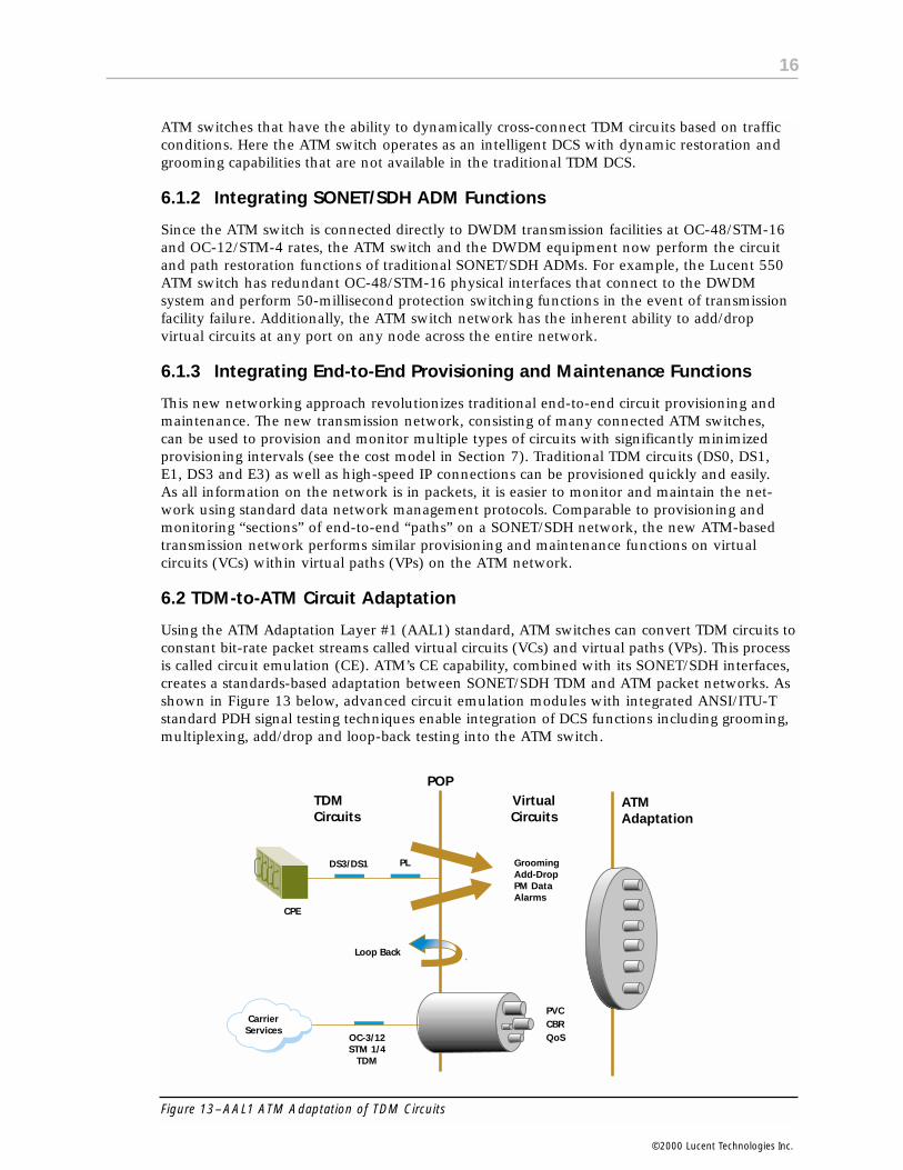
6.2 TDM-to-ATM Circuit Adaptation
Using the ATM Adaptation Layer #1 (AAL1) standard, ATM switches can convert TDM circuits toconstant bit-rate packet streams called virtual circuits (VCs) and virtual paths (VPs). This processis called circuit emulation (CE). ATM’s CE capability, combined with its SONET/SDH interfaces,creates a standards-based adaptation between SONET/SDH TDM and ATM packet networks. Asshown in Figure 13 below, advanced circuit emulation modules with integrated ANSI/ITU-Tstandard PDH signal testing techniques enable integration of DCS functions including grooming,multiplexing, add/drop and loop-back testing into the ATM switch.
Figure 13–AAL1 ATM Adaptation of TDM Circuits
ATM Adaptation
VirtualCircuits
POPTDMCircuits
GroomingAdd-DropPM DataAlarms
PVCCBRQoSOC-3/12
STM 1/4TDM
CarrierServices
Loop Back
CPE
DS3/DS1 PL
16
©2000 Lucent Technologies Inc.

TDM-to-ATM circuit emulation interfaces that have the capacity and testing capability of a traditional DCS are currently available on the Lucent PSAX 1250/2300 ATM MultiserviceSwitches. This interface functionality, combined with the multiservice switching capability ofthese Lucent ATM switches, creates the basis of a new transmission network that is ideal forprovisioning tomorrow’s mix of data-centric services.
Figure 14–The TDM to ATM Circuit Adaptation Function
As shown in Figure 14, these interfaces can convert traditional TDM circuits to ATM cells whileperforming ANSI/ITU standard testing and monitoring functions. With this functionality, TDMtraffic including DS0s, DS1s, E1s, DS3s, E3s, OC-3s, STM-1s, OC-12s and STM-4s can be trans-mitted across Lucent ATM switch networks (GX 550 and PSAX 1250/2300).
6.3 A New Transmission Network
This section examines the transmission network of the future—built around Lucent GX 550and PSAX 1250/2300 Multiservice ATM Switches that connect directly to DWDM facilities. Thisnew transmission network design delivers all the reliability, manageability, vendor interoper-ability and capacity of leading-edge SONET/SDH TDM networks, combined with the efficiencyand multiservice capability of ATM technology.
Now, the industry-leading Lucent GX 550 Multiservice ATM Switch, combined with the advancedcircuit emulation (CE) functionality of the PSAX 1250/2300 ATM Multiservice Switches, allowscarriers to build new transmission networks that will support tomorrow’s data-centric servicedemands as well as all legacy TDM network interfaces and functions. The network example inFigure 15 shows the full range of legacy TDM circuits and enhanced IP data services (such as IPMulti-Cast and VoIP) that can be provisioned over the network. Together, the ATM switches actas a multiservice transmission cloud, where TDM circuits and high-speed IP data services areprovisioned from end-to-end using virtual paths across the cloud.
Lucent GX 550 Multiservice
Switch
Lucent WaveStarOLS DWDM System
LucentPSAX 1250/2300
Multiservice Switches
Test Access
TDM to ATMCE Interface
Intra-OfficeFiber Optics
OC-12c/STM-4OC-3c/STM-1
OC-48/STM-16OC-12/STM-4
DS3/E3DS1/E1
DS0
17
©2000 Lucent Technologies Inc.
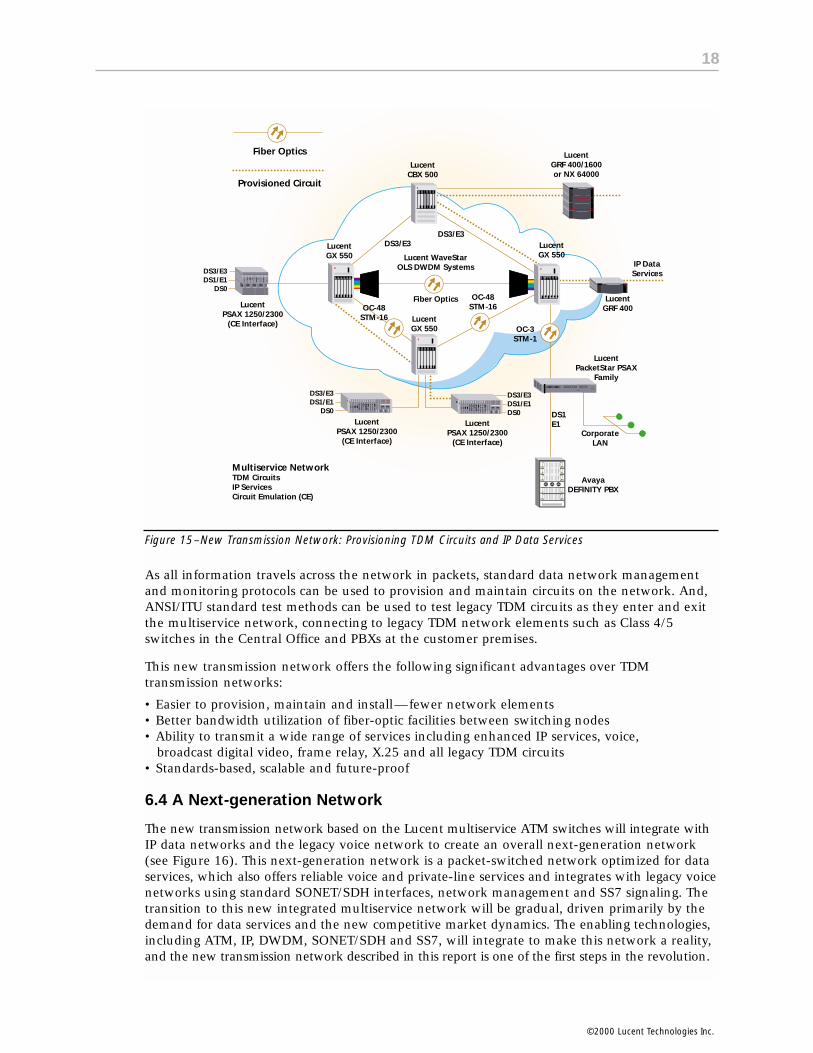
Figure 15–New Transmission Network: Provisioning TDM Circuits and IP Data Services
As all information travels across the network in packets, standard data network management and monitoring protocols can be used to provision and maintain circuits on the network. And,ANSI/ITU standard test methods can be used to test legacy TDM circuits as they enter and exitthe multiservice network, connecting to legacy TDM network elements such as Class 4/5switches in the Central Office and PBXs at the customer premises.
This new transmission network offers the following significant advantages over TDM transmission networks:
• Easier to provision, maintain and install—fewer network elements• Better bandwidth utilization of fiber-optic facilities between switching nodes• Ability to transmit a wide range of services including enhanced IP services, voice,
broadcast digital video, frame relay, X.25 and all legacy TDM circuits• Standards-based, scalable and future-proof
6.4 A Next-generation Network
The new transmission network based on the Lucent multiservice ATM switches will integrate withIP data networks and the legacy voice network to create an overall next-generation network(see Figure 16). This next-generation network is a packet-switched network optimized for dataservices, which also offers reliable voice and private-line services and integrates with legacy voicenetworks using standard SONET/SDH interfaces, network management and SS7 signaling. Thetransition to this new integrated multiservice network will be gradual, driven primarily by thedemand for data services and the new competitive market dynamics. The enabling technologies,including ATM, IP, DWDM, SONET/SDH and SS7, will integrate to make this network a reality,and the new transmission network described in this report is one of the first steps in the revolution.
DS3/E3DS1/E1
DS0
DS3/E3DS1/E1DS0
DS3/E3DS1/E1
DS0
Fiber Optics
Provisioned Circuit
LucentCBX 500
LucentGRF 400/1600or NX 64000
LucentGX 550
LucentGX 550
LucentGX 550
OC-48STM-16
OC-48STM-16
Fiber Optics
Lucent WaveStarOLS DWDM Systems
DS3/E3DS3/E3
IP DataServices
LucentGRF 400Lucent
PSAX 1250/2300(CE Interface)
LucentPSAX 1250/2300
(CE Interface)
AvayaDEFINITY PBX
LucentPSAX 1250/2300
(CE Interface)
OC-3STM-1
DS1E1
CorporateLAN
LucentPacketStar PSAX
Family
Multiservice NetworkTDM CircuitsIP ServicesCircuit Emulation (CE)
18
©2000 Lucent Technologies Inc.

Figure 16–The next-generation network is a true multiservice network, supporting legacy voice and private-lineservices as well as tomorrow’s high-speed, data-centric services, using standard technologies including ATM,DWDM, SONET/SDH, xDSL, SS7 Signaling and IP. The resulting carrier benefit is a competitive scalable networkinfrastructure that profitably supports provisioning of leading-edge information services.
Provisioning and Maintenance Cost Model—Five-Node NetworkWith the new ATM transmission network approach, competitive carriers now have the opportunityto cut costs associated with purchasing 2, installing, provisioning and maintaining transmissionequipment required to support private-line and data service offerings. Appendix A uses a five-node network example to demonstrate the magnitude of operational cost savings made possibleby constructing transmission networks using Lucent multiservice ATM switches with integratedOC-48/STM-16 SONET/SDH transport, DCS functionality and advanced Navis provisioning software.
This network model is a five-node linear OC-48/STM-16 network that can add/drop DS3/E3private-line traffic as well as various types of high-speed data traffic at every node. To make aconservative comparison, the SONET/SDH TDM network model is based on leading-edge SONET/SDH ADM and DCS equipment, where the DCS has OC-12/STM-4 and OC-3/STM-1 interfacecapability. The model does not consider the provisioning or maintenance of access circuits.
OC-3STM-1
LucentGX 550
LucentGX 550
ISDN56/64 Kbps
Dial-upData
Lucent MAX TNT
SS7 Signaling Network
IP Telephony& FaxLucent
Softswitch
Internetor Private
IP Network
LucentGRF 400/1600or NX 64000
IP
Lucent MAX TNT
Legacy PSTN
Lucent PacketStar PSAX
Family
DS1/E1Corporate
LAN
AvayaDEFINITY PBX
Fiber Optics
Lucent WaveStarOLS DWDM Systems
MultiserviceTransmission
End-to-EndProvisioning
Navis
LucentWaveStar™ FamilySONET/SDH ADM
OC-12/STM-4
OC-3/STM-1
LucentDACS FamilyDCS
DS1/E1DS3/E3
OC-3/STM-1
POTS Lucent 4/5ESSVoice Switch
DS1/E1DS3/E3OC-3/STM-1
LucentSoftswitch
Fiber Optics
Copper/Coxial Cable
Signaling
7.
19
2 Although Appendix A does not compare the capitol equipment cost of each network approach, it is anticipated that signifi-cant equipment cost savings can be achieved with the ATM transmission network built on Lucent multiservice switches as described in this report. Independant cost comparisons performed by Lucent customers including Williams Communications, Inc. predict an overall cost savings of up to 70 percent using the ATM multiservice network approach. For more information, service providers can ask their Lucent sales representative about a customized cost comparison for their particular network.
©2000 Lucent Technologies Inc.
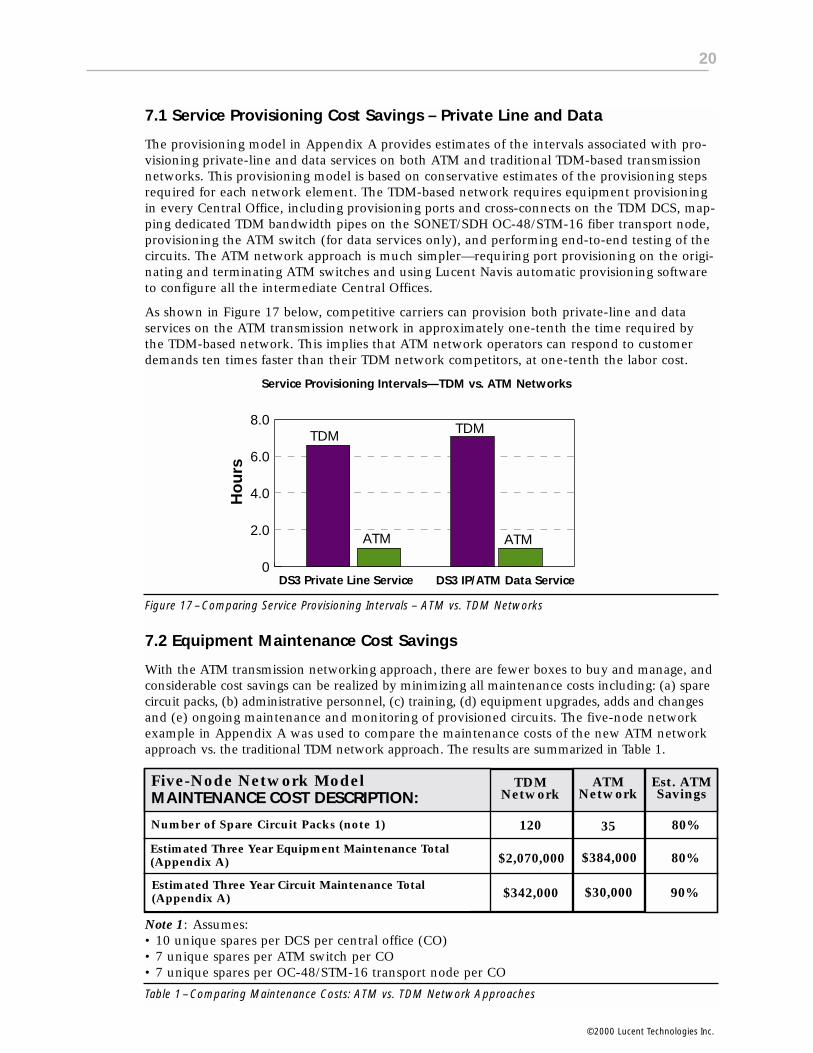
7.1 Service Provisioning Cost Savings – Private Line and Data
The provisioning model in Appendix A provides estimates of the intervals associated with pro-visioning private-line and data services on both ATM and traditional TDM-based transmissionnetworks. This provisioning model is based on conservative estimates of the provisioning stepsrequired for each network element. The TDM-based network requires equipment provisioningin every Central Office, including provisioning ports and cross-connects on the TDM DCS, map-ping dedicated TDM bandwidth pipes on the SONET/SDH OC-48/STM-16 fiber transport node,provisioning the ATM switch (for data services only), and performing end-to-end testing of thecircuits. The ATM network approach is much simpler—requiring port provisioning on the origi-nating and terminating ATM switches and using Lucent Navis automatic provisioning softwareto configure all the intermediate Central Offices.
As shown in Figure 17 below, competitive carriers can provision both private-line and data services on the ATM transmission network in approximately one-tenth the time required bythe TDM-based network. This implies that ATM network operators can respond to customerdemands ten times faster than their TDM network competitors, at one-tenth the labor cost.
Figure 17–Comparing Service Provisioning Intervals – ATM vs. TDM Networks
7.2 Equipment Maintenance Cost Savings
With the ATM transmission networking approach, there are fewer boxes to buy and manage, andconsiderable cost savings can be realized by minimizing all maintenance costs including: (a) sparecircuit packs, (b) administrative personnel, (c) training, (d) equipment upgrades, adds and changesand (e) ongoing maintenance and monitoring of provisioned circuits. The five-node networkexample in Appendix A was used to compare the maintenance costs of the new ATM networkapproach vs. the traditional TDM network approach. The results are summarized in Table 1.
Note 1: Assumes: • 10 unique spares per DCS per central office (CO)• 7 unique spares per ATM switch per CO• 7 unique spares per OC-48/STM-16 transport node per CO
Table 1–Comparing Maintenance Costs: ATM vs. TDM Network Approaches
0
2.0
4.0
6.0
8.0TDM TDM
ATM ATM
DS3 Private Line Service DS3 IP/ATM Data Service
Ho
urs
Service Provisioning Intervals—TDM vs. ATM Networks
Five-Node Network ModelMAINTENANCE COST DESCRIPTION:
Number of Spare Circuit Packs (note 1)
Estimated Three Year Equipment Maintenance Total (Appendix A)
Estimated Three Year Circuit Maintenance Total (Appendix A)
TDMNetwork
ATMNetwork
Est. ATMSavings
120 35 80%
$2,070,000 $384,000 80%
$342,000 $30,000 90%
20
©2000 Lucent Technologies Inc.

Looking at the Appendix A network example, it is evident that maintaining the traditional TDMnetwork is more costly than the new ATM network approach. The TDM network approach willrequire an estimated four times the number of spare circuit packs in the five-node networkexample. Likewise, overall equipment maintenance (administrative personnel and training) forthe TDM network is estimated as five times more costly than the ATM network.
The advanced features supported by Lucent multiservice ATM switches, such as automatic pro-visioning and reconfiguration, built-in test capabilities and customer network management gateways,help to minimize the ongoing cost of maintaining provisioned customer circuits. As shown inTable 1, ongoing circuit maintenance including service upgrades, changes and performancemonitoring are an estimated ten times less expensive using the ATM network approach.
7.3 Other Cost Savings
Although not quantified in the Appendix A network example, all the advantages of an ATMtransmission infrastructure approach (described earlier in section 5.2) represent either a costsavings or a competitive advantage for the ATM network operator. For example, while theeffective bandwidth management capability of the ATM networking approach is not quantifiedin Appendix A, it is very significant. This capability can cut the carrier’s overall cost of servicesignificantly by allowing the carrier to oversubscribe expensive WAN facilities and derive morerevenue from less bandwidth.
Another advantage of the ATM infrastructure approach discussed earlier but not shown in theAppendix A analysis, is the ability to support premium service offerings such as higher-speedservices (DS3/E3 and greater), varied quality of service offerings, bandwidth on demand, andtime-of-day service options. As all of these premium services are more difficult and costly toprovision on traditional TDM-based networks, they will likely become a significant competitiveadvantage for emerging ATM network operators.
This five-node network example compares the service provisioning and maintenance costs forproviding “DS3/E3 private line” and “DS3/E3 IP/ATM data service” using two transmission networking approaches.
(1) The traditional SONET/SDH TDM network approach:
DESCRIPTION: The traditional TDM approach includes an ATM switch, DCS and OC-48/STM-16 transport nodes at each Central Office. The SONET/SDH DCS is configured optimally, interfacing the ATM switch at the DS3/E3 and OC-3/STM-1 rates, and interfacing the OC-48/STM-16 transport at the OC-12/STM-4 rate. Both the DCS and the ATM switch can interface access circuits (ingress traffic) asrequired at the DS1/E1, DS3/E3 and OC-3/STM-1 rates.
ATM
DCS
DWDM
OC48
STM16
ATM
DCS
DWDM
OC48
STM16
CO #2, #3, #4
FR, ATM, IPDataServiceand Private-line Services
FR, ATM, IPDataServiceand Private-line Services
Central Office #1 Central Office #5
NOTE : OC48/STM16 box represents an OC-48/STM-16 transport
21
Appendix A: Five-Node Cost Model—Service Provisioning and Maintenance
©2000 Lucent Technologies Inc.

(2) The new ATM-based network approach:
DESCRIPTION: The new ATM approach includes a multiservice ATM switch equipped with OC-48/STM-16transport interfaces, OC-3/STM-1 ATM interfaces and DS1/DS3 (E1//E3) circuit emulation interfaces ateach Central Office. The ATM switch connects to access circuits (ingress traffic) as required at the DS1/E1,DS3/E3 and OC-3/STM-1 rates.
Network Assumptions
• The five-node OC-48/STM-16 network can add/drop DS3/E3 private-line traffic, as well as various types of high-speed data traffic, at every node.
• The SONET/SDH TDM network is based on leading-edge SONET/SDH ADM and DCS equip-ment, where the DCS has OC-12/STM-4 and OC-3/STM-1 interface capability.
• DCS connects to the OC-48/STM-16 transport at the OC-12/STM-4 rate or equivalent—all interconnections (trunks) between network elements are already made during initial installation.
Service Assumptions
• Demand for a multiservice mix including private-line (DS1/DS3 or E1/E3) and data services (IP, ATM, FR).
• Model assumes “DS3/E3 Private Line” and ”DS3/E3 IP/ATM Data Service.”
Notes
• The provisioning costs of the various access network alternatives are not included in the model.
DWDM
DWDM
CO #2, #3, #4
Central Office #1 Central Office #5
Private-lineandFR, ATM, IPData Services
ATM
CE or IPInterface
Private-lineandFR, ATM, IPData Services
ATM
CE or IPInterface
ATM
DCS
DWDM
OC48
STM16
ATM
DCS
DWDM
OC48
STM16
CO #2, #3, #4DS3/E3or
DS1/E3Private
Line
DS3/E3orDS1/E1PrivateLineCentral Office #1 Central Office #5
Provisioning DS3/E3 and DS1/E1 Private Lines on the traditional TDM Network
PROVISIONINGSTEP #
1, 2 3 4,567
PROVISIONINGSTEP #
Traditional SONET/SDH-based TDM Network Approach—Five-Node Networking Provisioning Model
Step #1: Provision physical DS3/E3 or DS1/E1 ingress interface on DCS in CO #1 0.3Step #2: Provision DCS to cross-connect to OC-12/STM-4 interface in CO #1 0.3Step #3: Provision DS3 mapping on OC-48/STM-16 transport node at CO #1 0.5Step #4: Provision physical DS3/E3 or DS1/E1 ingress interface on DCS in CO #5 0.3Step #5: Provision DCS to cross-connect to an OC-12/STM-4 interface in CO #5 0.3Step #6: Provision DS3 mapping on OC-48/STM-16 transport node at CO #5 0.5Step #7: Provision a dedicated DS3/E3 or DS1/E1 circuit across the TDM Network 3.3
requiring the same TDM equipment configuration steps perintermediate Central Office node. (.3 + .3 + .5= 1.1 hours per CO) 5.5 Total Hours
Est. Hours
22
©2000 Lucent Technologies Inc.

ATM
DCS
DWDM
OC48
STM16
ATM
DCS
DWDM
OC48
STM16
CO #2, #3, #4DS3/E3IP/ATM
DataService
DS3/E3IP/ATMDataService
Central Office #1 Central Office #5
Provisioning DS3/E3 IP Connectivity Service on the traditional TDM Network
PROVISIONINGSTEP #
1, 2 3 4,567
PROVISIONINGSTEP #
DWDM
DWDM
CO #2, #3, #4
Central Office #1 Central Office #5
ATM
CE or IPInterface
ATM
CE or IPInterface
DS3/E3 orDS1/E1Private
Line
DS3/E3 orDS1/E1PrivateLine
1 2 345
Provision physical DS3/E3 Ingress Interface on DCS at CO #1 0.3Provision DCS to cross-connect ingress DS3/E3 to ATM Switch in CO #1 0.3Provision DS3/E3 interface on ATM Switch at CO #1 0.1Provision DS3/E3 logical port parameters on ATM Switch in CO #1 0.1Provision DS3/E3 circuit mapping on OC-48/STM-16 transport at CO #1 0.5Provision physical DS3/E3 ingress interface on DCS at CO # 5 0.3Provision DCS to cross-connect ingress DS3/E3 to ATM Switch in CO #1 0.3Provision DS3/E3 interface on ATM Switch at CO #5 0.1Provision logical DS3/E3 port parameters on ATM Switch in CO #5 0.1Provision DS3/E3 circuit mapping on OC-48/STM-16 transport at CO #5 0.5Provision a dedicated OC-3/STM-1 circuit across the TDM Network 3.3requiring the same TDM equipment configuration steps perintermediate Central Office node. (.3 + .3 +.5= 1.1 hours per CO) 5.9 Total Hours
Est. HoursStep #1:
Step #1a:Step # 2:
Step # 2a:Step # 3:Step # 4:
Step # 4a:Step # 5:
Step # 5a:Step # 6:
Step # 6a:
The ATM-Switch-based Network Approach—Five-Node Network Provisioning Model
Configure physical DS3/E3 or DS1/E1 CE interface port at CO #1 0.1Configure logical port parameters in ATM Switch at CO #1 0.1Configure physical DS3/E3 or DS1/E1 CE interface port at CO #5 0.1Configure logical port parameters in ATM Switch at CO #5 0.1Use Navis Xtend Provisioning Server and SNMP to set up 0.1virtual circuit across the entire ATM network, between ports.
0.5 Total Hours
Est. HoursStep #1:Step #2:
Step # 3:Step # 4:Step # 5:
Provisioning DS3/E3 and DS1/E1 Private Lines on the ATM Network
23
©2000 Lucent Technologies Inc.
ATM NETWORK PROVISIONING (5 CENTRAL OFFICES)

PROVISIONINGSTEP #
DWDM
DWDM
CO #2, #3, #4
Central Office #1 Central Office #5
ATM
IP/ATMInterface
ATM
IP/ATMInterface
DS3/E3 orOC-3/
STM-1 IPService
DS3/E3 orOC-3/STM-1 IPService
2 1 435
Circuit Provisioning Labor Cost per Hour $100On-Going Circuit Maintenance Factor 20%
Service Provisioning Costs
# of Circuits Prov. Hours
Total Prov. Cost
500500
0.50.5
$25,000$25,000
Five Node Network Maintenance
DCS Maintenance
# of Net. Admins.
Central Offices
Loaded***Net Admin.Salary/Yr
0 0 $64,000
OC-48/STM-16 Transport Node Maintenance
ATM Switch Maintenance
0 0 $64,000
1 2 $64,000
InitialCost
Cost SubTotals $128,000 $128,000 $128,000
Annual Maintenance CostsYear 1 Year 2 Year 3
$ - $5,000 $5,000 $5,000$ - $5,000 $5,000 $5,000
Cost SubTotals $10,000 $10,000 $10,000
$ - $0 $0 $0
$ - $0 $0 $0
$ - $128,000 $128,000 $128,000
* Total Three Year Equipment Maintenance Cost $384,000
** Total Three Year Circuit Maintenance Cost $30,000
Total: $414,000
DS3/E3 Private-line ServiceDS3/E3 IP/ATM Data Service
Configure physical DS3/E3 or OC-3/STM-1port on ATM Switch at CO #1 0.1Configure logical port & IP Service Parameters on CO #1 0.1Configure physical DS3/E3 or OC-3/STM-1 port ATM Switch at CO #5 0.1Configure logical port & IP Service Parameters at CO #5 0.1Use IP Navigator and Navis Xtend to provision an IP stream 0.1across the entire ATM network—with desired QoS parameters.
0.5 Total Hours
Est. HoursStep #1:Step #2:
Step # 3:Step # 4:Step # 5:
Provisioning DS3/E3 or OC-3/STM-1 IP/ATM Service on the ATM Network
ATM-based Transmission Network—Maintenance Labor Cost Model
Circuit Provisioning Labor Cost per Hour $100On-Going Circuit Maintenance Factor 20%
Service Provisioning Costs
DS3/E3 Private-line ServiceDS3/E3 IP/ATM Data Service
# of Circuits Prov. Hours
Total Prov. Cost
500500
5.55.9
$275,000$295,000
Five Node Network Administration
DCS Maintenance
# of Net. Admins.
Central Offices
Loaded***Net Admin.Salary/Yr
1 5 $64,000
OC-48/STM-16 Transport Node Maintenance
ATM Switch Maintenance
1 2 $64,000
1 2 $64,000
InitialCost
Cost SubTotals $576,000 $576,000 $576,000
Annual Maintenance CostsYear 1 Year 2 Year 3
$ - $55,000 $55,000 $55,000$ - $59,000 $59,000 $59,000
Cost SubTotals $114,000 $114,000 $114,000
$ - $320,000 $320,000 $320,000
$ - $128,000 $128,000 $128,000
$ - $128,000 $128,000 $128,000
* Total Three Year Equipment Maintenance Cost $1,728,000
** Total Three Year Circuit Maintenance Cost $342,000
Total: $2,070,000
TDM-based Transmission Network—Maintenance Labor Cost Model
* NOTE: Includes equipment upgrades, repair & maintenance.
** NOTE: Includes circuit monitoring & test, service changes, etc.
*** NOTE: Loaded Network Administrator salary cost includes training.
Configuration Summary % of TotalDS3/E3 Private Line Circuits 500 50%DS3/E3 IP/ATM Data Circuits 500 50%
Network Maintenance Comparison TDM ATM
Equipment Maintenance: $1,728,000 $384,000Circuit Maintenance: $342,000 $30,000
$2,070,000 $414,000
24
©2000 Lucent Technologies Inc.

Many incumbent service providers designed and built their network infrastructure decades ago.The primary technology at that time was Time Division Multiplexing (TDM) and the primaryapplication was voice. With TDM, a fixed-sized “channel” or “time slot” is allocated for the durationof the call. Voice traffic works best when it has a fixed, dedicated amount of bandwidth withvery little delay; therefore, the technology perfectly fits the application.
By the late 1980s, data communications was becoming an increasing requirement. Corporatecustomers with private leased lines were terminating those lines with TDM multiplexers andallocating fixed channels to voice and data traffic. Carriers began to realize that they were los-ing revenue and needed to support data traffic for their customers (generate new revenuestreams). The first public data networks were created using X.25 packet technology over the TDMinfrastructure. The migration to faster frame relay networks occurred in the early to mid-1990s.These data networks continue to be an “overlay” on top of the existing TDM infrastructure.
To increase the capacity of this TDM infrastructure, carriers have deployed high-speed opticalbackbones using SONET/SDH technology that allows big digital bandwidth “pipes” to be provi-sioned across fiber networks. SONET/SDH provides a high-speed, reliable infrastructure thathas been proven over the last decade. Currently, the fastest SONET/SDH rate available is OC-192, the equivalent of 10 Gbps. Most of the SONET/SDH networks deployed today are OC-48/STM-16 (2.4 Gbps), OC-12/STM-4 (622 Mbps) and OC-3/STM-1 (155 Mbps). No mat-ter how big the SONET/SDH “pipes” are, if the pipes are channelized using TDM technology,they are very inefficient for carrying bursty, inherently variable, data traffic. Figure B-1 depictsthe differences in running data over a circuit network versus a packet network. Note the emptyspace in the circuit-switched pipe; this signifies wasted bandwidth.
Figure B-1
The main issue with sending bursty data traffic over fixed physical circuits is that network man-agers must provision the physical layer for peak bandwidth requirements. Given the bursty,unpredictable nature of data traffic, the application may need peak bandwidth rates only 10percent of the time. The rest of the time, much of the bandwidth goes unused. This is like usinga shuttle bus to provide taxi service from an airport. Most of the time you will have one or twopassengers, and once in a while you may get a full busload.
Packet Switched Network
Circuit Switched Voice Network
Information Packet
Address Header
25
Appendix B: Packet Switching vs. Circuit Switching
©2000 Lucent Technologies Inc.