recovery from control plane failures in the rsvp-te ...jingwu/publications/journal/recovery...
TRANSCRIPT
Computer Communications 34 (2011) 1956–1967
Contents lists available at ScienceDirect
Computer Communications
journal homepage: www.elsevier .com/ locate/comcom
Recovery from control plane failures in the RSVP-TE signaling protocol
Jing Wu ⇑, Michel SavoieCommunications Research Centre Canada, 3701 Carling Avenue, Ottawa, Ontario, Canada K2H 8S2
a r t i c l e i n f o a b s t r a c t
Article history:Received 23 July 2009Received in revised form 31 May 2011Accepted 1 June 2011Available online 17 June 2011
Keywords:GMPLS control planeSignaling protocolRSVP-TEControl plane failure recoveryGraceful Restart
0140-3664/$ - see front matter Crown Copyright � 2doi:10.1016/j.comcom.2011.06.001
⇑ Corresponding author. Tel.: +1 613 9982474; fax:E-mail addresses: [email protected] (J. Wu), michel
The Resource Reservation Protocol for Traffic Engineering (RSVP-TE) must recover its state after a controlplane failure so that the established connections in the data plane continue to be provided full services,are not disrupted by new connection setup requests, and survive any data plane failures. We outline theRSVP-TE Graceful Restart (GR) mechanism defined by the IETF. In this paper, we provide a comprehensivesurvey of the information that may be carried by RSVP-TE signaling messages when a connection is to beestablished and the state information that is stored in an RSVP-TE signaling module. We then propose anenhancement for RSVP-TE GR to alleviate the requirement of local recovery of the data plane state. Ourproposal includes a two-step RSVP-TE state recovery, which uses a fast recovery to recover the RSVP-TEstate in which labels were idle before a control plane failure and a detailed recovery to recover all of theRSVP-TE state. The fast RSVP-TE state recovery is realized as an extension to the RSVP-TE Hello mecha-nism, allowing a restarting node to process new connection setup requests as quickly as possible withoutinterfering with existing connections. The detailed RSVP-TE state recovery generally follows RSVP-TE GRwith minor modifications that can be performed in the background in parallel with normal RSVP-TE oper-ations for connection setup and removal. Our performance evaluations show that our proposal shortensthe waiting time for new connection setups being processed by a restarting node.
Crown Copyright � 2011 Published by Elsevier B.V. All rights reserved.
1. Introduction
Control plane reliability is critical for efficient operation of next-generation networks [1]. New-generation Multi-Protocol LabelSwitching (MPLS) switches/routers are able to maintain labelswitching states in the data plane following control plane failuresor during their maintenance [2]. In a Generalized Multi-ProtocolLabel Switching (GMPLS) network, failures in the control and dataplanes occur more or less independently when they are physicallyseparate [3–7]. In planned control plane maintenance or accidentalcontrol plane failures, methods are required to minimize serviceinterruptions to data plane connections.
The Resource Reservation Protocol for Traffic Engineering(RSVP-TE) is a signaling protocol for MPLS and GMPLS networks.IETF defines traffic engineering extensions to the RSVP so that con-nections can be established, maintained and removed in an MPLSnetwork [8]. The RSVP-TE is also the preferred signaling protocolfor GMPLS-controlled circuit-switched networks [9–11]. Betweentwo neighbors, an RSVP-TE session is used to exchange RSVP-TEmessages and control the corresponding data plane links.
The RSVP-TE Graceful Restart (GR) mechanism enables arestarting node to recover its lost RSVP-TE state. An RSVP-TE ses-sion terminates when its two end nodes cannot communicate for
011 Published by Elsevier B.V. All
+1 613 [email protected] (M. Savoie).
a certain period or when either of the two nodes fails. A failed nodemay lose its RSVP-TE state completely or lose the synchronizationof its RSVP-TE state with its neighbors on restart. RSVP-TE GR re-quires that all the states of an RSVP-TE session should be redun-dantly stored in the upstream and downstream neighbors of thesession [10,12]. A restarting node can then recover its RSVP-TEstate from its neighbors. RSVP-TE GR may recover the RSVP-TEstate in any single-point failure.
RSVP-TE GR requires a restarting node to locally recover or re-trieve its related data plane state. As a subset of the RSVP-TE state,the data plane state reflects the state of the resources that are vis-ible to neighbors, such as incoming or outgoing ports. The dataplane state is modified using RSVP-TE as connections are set upor removed. The key data plane state is defined by forwarding ta-bles in MPLS networks or cross-connection tables in GMPLS net-works. An MPLS forwarding table maintains key informationspecifying the appropriate incoming and outgoing label/port map-ping [13]; a GMPLS cross-connection table maintains incoming andoutgoing timeslot/wavelength-channel/port mapping.
RSVP-TE GR cannot operate properly if a restarting node doesnot recover its data plane state first. RSVP-TE GR processes connec-tion setup requests while the RSVP-TE state is being recovered.New connection setups and the RSVP-TE state recovery are con-ducted independently and in parallel. Without the data plane re-source state being recovered, there is a potential risk that a newconnection setup may accidentally disrupt an existing connection
rights reserved.
J. Wu, M. Savoie / Computer Communications 34 (2011) 1956–1967 1957
by using resources allocated to it. RSVP-TE GR verifies the recov-ered RSVP-TE state by comparing it with the locally recovered dataplane state (Section 4.5.2.2 of [12]).
The local recovery or retrieval of the data plane state may beimpossible or unfavorable for switching elements. Local recoverywithout information exchange with neighbors is a challenge andmay not be accomplished by all switching elements. First, a nodefailure may lose or damage the data plane state, even though thehardware in the switching elements keeps existing connectionsoperating. Second, not all switching elements are able to providethe preserved MPLS forwarding tables or GMPLS cross-connectiontables to their restarting RSVP-TE module.
Our design goal is to extend the RSVP-TE GR so that the require-ment of local recovery of the data plane state is not mandatory. Inour proposed enhanced RSVP-TE GR, this requirement becomes op-tional. If the data plane state is successfully locally recovered, it canbe used to assist the RSVP-TE state recovery, for example, for theverification of recovered information from an RSVP-TE neighboror to speed up recovery. However, our design solely relies on infor-mation from neighbors. This is the key contribution of this paper.
We provide an informational clarification and performanceevaluation of the procedural process of connection removal re-quests during the recovery. Because a restarting node may receiveconnection removal requests during its recovery, it must coordi-nate the processing of the requests and its recovery. This has notbeen clearly defined by the IETF and is the second contributionof this paper.
In this paper, we provide a comprehensive survey of the infor-mation that may be carried by RSVP-TE signaling messages whena connection is to be established and the state information thatis stored in an RSVP-TE signaling module. Over the past 15 years,RSVP and RSVP-TE have been continuously developed and ex-tended. The extensions are scattered in many IETF standards. Weprovide a survey of the information carried by RSVP-TE signalingmessages and an outline of the related RSVP-TE state informationso that the scale of RSVP-TE state recovery discussed in this papercan be assessed. This is the third contribution of this paper.
This paper is organized as follow. In Section 2, we discuss recov-ery time requirements of the GMPLS protocols. In Section 3, wepresent an overview of the RSVP-TE GR and outline the RSVP-TEoperations for GMPLS-controlled optical networks. We propose atwo-step RSVP-TE state recovery in Section 4, followed by perfor-mance evaluation results in Section 5. We conclude the paper inSection 6. A complete view of the state related to RSVP-TE sessionsand Path and Resv messages is given in the Appendix A.
2. Recovery time requirements of the GMPLS protocols
GMPLS protocols play important roles in data plane failure res-toration and shared protection. The biggest value of building a sep-arate GMPLS control plane is to save data plane resources used forprotection. Compared with 1 + 1 or 1:1 protection, significant sav-ings may be achieved by using restoration and shared protection[14]. However, these approaches need signaling protocols for rapidfault notification and data plane connection setup or switchover.The target time is 200–300 ms and 100–200 ms to restore a faileddata plane connection and complete a shared protection, respec-tively [15].
The failure recovery time of the GMPLS protocols varies. Thesignaling protocol availability directly impacts the survivabilityof data plane connections. With an increase of the out-of-servicetime of signaling protocols due to a control plane failure, there isan increased risk of data plane connections not being protectedor restored in time. In this sense, the signaling protocol recoveryis service impacting, and data plane connections are affected. In
contrast, the only rule of the Link Management Protocol (LMP) ina failure recovery is fault isolation, which is a maintenance actionand does not have a strict time requirement [4]. A restoration of afailed data plane connection must search for an alternative route inthe Traffic Engineering Database (TED), which is populated byrouting protocols [16,17]. Before routing protocols recover from acontrol plane failure, their link state advertisements are postponed,resulting in the TED not being updated. However, a connection set-up tolerates the inaccuracy of the TED even in the normal state be-cause the TED is often out-of-date due to its distributed updatingprocess. Consequently, the time requirement of the routing proto-col recovery is not critical.
3. Overview of the RSVP-TE GR mechanism
3.1. Overview of the RSVP-TE operations for GMPLS controlled opticalnetworks
In this paper, our major focus is the RSVP-TE operations forGMPLS-controlled optical networks. RSVP-TE has been chosen asthe preferred GMPLS signaling protocol [11]. The original RSVPwas proposed to support resource reservation and Quality of Ser-vice (QoS) in packet networks [18,19]. Since then, many enhance-ments have been proposed and standardized. For the latestprogress, refer to work in the two IETF working groups: commoncontrol and measurement plane [20] and MPLS [21]. Our discus-sions apply to the RSVP-TE extensions for establishing, maintainingand removing point-to-point unidirectional connections (i.e., light-paths) in GMPLS-controlled optical networks. Other applicationsmay need modifications, but the proposed concept and frameworkremain largely valid. We assume the control plane is secured andcontrol nodes trust each other; no RSVP-TE security feature to pre-vent intrusions is considered.
RSVP-TE uses Path and Resv messages to establish connections.Path messages are sent downstream from the head (i.e., ingress) tothe tail (i.e., egress) of a connection, following a computed route[19]. Resv messages are sent upstream, following the same routebut in the opposite direction. The ingress creates an entry in itsstate base and then sends out a Path message. Upon receipt of aPath message, an intermediate control node creates an entry inits state base and then generates another Path message to senddownstream. The same process repeats until a Path message ar-rives at the egress. The egress makes necessary resource reserva-tions, updates its corresponding state entry, and generates a Resvmessage to send upstream. Upon receipt of a Resv message, anintermediate control node makes resource reservations and neces-sary cross-connections, updates its corresponding state entry, andgenerates a Resv message to send upstream. The same process re-peats until a Resv message arrives at the ingress. To establish con-nections in GMPLS-controlled optical networks, Path and Resvmessages carry additional information, such as generalized labelobjects [10]. A complete list of the up-to-date defined objects inPath and Resv messages by the IETF is shown in Table 1. The de-tailed RSVP-TE state is given in the Appendix A.
The entry for a given connection in a state base is identified by theconnection’s source and destination nodes, and if necessary, a con-nection ID. The ‘‘Session’’ object carries the destination node (i.e.,egress) in all Path and Resv messages. The ‘‘Sender template’’ objectcarries the source node (i.e., ingress) in all Path messages, while the‘‘Filter spec’’ object carries the source node in all Resv messages.When there are multiple connections between the same ingress-egress pair, a connection ID (i.e., Label Switched Path – LSP ID)may be added in the ‘‘Sender template’’ or ‘‘Filter spec’’ objects [8].
In this paper, our discussions are not limited to any particularinformation model of the RSVP-TE state. The information model
Table 1Objects in Path and Resv messages.
Objects Descriptions Mandatory oroptional inPath messages
Mandatory oroptional inResv messages
ReferenceIETF RFCs
Common header Message type, total length of this RSVP message, etc. Mandatory Mandatory [19]Session An RSVP session’s destination (i.e., egress) IP address and port, IP
protocol IDMandatory Mandatory [19,8]
RSVP hop The IP address and data plane interface of the node that sent thismessage. It is a ‘‘previous hop’’ object for a downstream messageor a ‘‘next hop’’ object for an upstream message.
Mandatory Mandatory [19]
Time values The time period that the sender uses to refresh this message Mandatory Mandatory [19]Label request Request a label to establish an LSP tunnel Mandatory [8,10]Sender template An RSVP session’s source (i.e., ingress) IP address and optional
information, such as the ingress’s port, LSP IDMandatory [19,8]
Sender TSPEC The traffic characteristics of a data flow Mandatory [19,22,23]Filter spec Identical to the ‘‘sender template’’ Mandatory [19,8]Flowspec A desired QoS Mandatory [19,22,23]Style Reservation style Mandatory [19]RSVP label Label allocated for this connection Mandatory [8,10]Integrity Cryptographic data to authenticate the originating node and
verify the contents of this messageOptional Optional [19]
Message ID; Message ID ACK/NACK;Message ID list
Support acknowledgments and reliable RSVP message delivery,summary refresh extension
Optional Optional [24]
Notify request; Alarm spec Identify where event notifications are to be sent, and what alarminformation should be sent
Optional Optional [10,25]
Session of interest Support RSVP session aggregation Optional Optional [26]Diffserv Support differentiated services Optional [27]Admin status Administrative state of a particular LSP Optional Optional [10]Policy data Information for a local policy module to decide whether the
associated reservation is administratively permittedOptional Optional [19]
Record route Record a route to collect detailed path information Optional Optional [8]Explicit route; Exclude route A particular path that is described as a group of nodes that must
or must not be traversedOptional [8,28]
Label set; Suggested label The set of labels that downstream nodes can choose from, or theupstream node’s label preference
Optional [9,10]
Session attribute; LSP attributes; LSPrequired attributes
Attributes required to support an LSP, such as setup and holdingpriorities, resource affinities, local protection, and fast re-reroutefunctionality
Optional [8,29,30]
ADSPEC Enable nodes in the path to advertise their service capabilities,resource availability, and transmission characteristics
Optional [19]
Recovery label Support the RSVP Graceful Restart by providing the label incorresponding Resv messages
Optional [10]
Upstream label Support bidirectional LSP setup Optional [10]Protection; Association; Primary path route;
Detour; Fast reroute; Secondary recordroute; Secondary explicit route
Support protection of an LSP, for example, associating a recoveryLSP with the LSP it is protecting, indicating the branch and mergenodes of recovery LSPs, etc.
Optional [10,31,32,29]
Resv confirm The IP address of the receiver that requested a confirmation Optional [19]Scope Senders towards which this message is to be forwarded Optional [19]
1958 J. Wu, M. Savoie / Computer Communications 34 (2011) 1956–1967
that a node uses to store its RSVP-TE state varies in different imple-mentations. In general, the RSVP-TE state is stored in path and res-ervation state blocks, as well as in other state storage modules. Arelational information model was used to present an algorithmicdescription of the RSVP message processing rules in [33]. A rela-tional style search was used to find state blocks in [33], althoughthe state blocks were not required to be stored in a relational data-base. Objects are used to present the processing rules on the basisof object relationships between state blocks in a prototype RSVPimplementation [34–36]. The state information was representedas relations, and their functional dependencies were identified.The relationships between objects were explicitly stored. The ob-ject relationships are generally more expressive and efficient thanfinding state blocks on the basis of relational rules.
Additional RSVP-TE messages are defined for confirmation, con-nection removal, error report and notification. These messages areoptional in some RSVP-TE operation modes, but using them im-proves the RSVP-TE performance. For example, PathTear and Resv-Tear messages remove state promptly [19]. PathErr and ResvErrmessages report errors in Path and Resv messages, such as param-eter errors [19]. A ResvConfirm message explicitly confirms the suc-cess of processing a Resv message [19]. A node may send a Notify
message to another node, targeting either its immediate neighboror a non-adjacent node [10].
Although RSVP-TE supports a soft-state approach, an increasingtrend is to operate RSVP-TE in a hard-state manner for GMPLS-con-trolled optical networks. When RSVP-TE operates in a soft-statemanner, it requires sending periodic refresh Path and Resv mes-sages. Failure to receive a certain number of consecutive refreshPath or Resv messages normally results in a timeout and removalof the corresponding state [19]. In GMPLS-controlled optical net-works, the removal of established connections due to control planefailures should be prevented [6,7]. A solution is operating RSVP-TEin a hard-state manner by disabling the state timeout mechanism.However, this solution should only be used with the reliable deliv-ery of trigger messages. Otherwise, if a trigger message is lost, theconnection may never be established or removed [37]. Reliabledelivery of messages can be achieved by using ACK messages andproper re-transmission of lost messages [24].
3.2. Standard RSVP-TE GR mechanism
RSVP-TE GR enhances two aspects of RSVP-TE: the Hello mech-anism and the restarting and recovery behaviors. In addition to
J. Wu, M. Savoie / Computer Communications 34 (2011) 1956–1967 1959
detecting the reachability of a neighbor control node [8], the Hellomechanism is extended to diagnose the failure type (a controlchannel or node failure) [10] and announce the GR capability andassociated parameters [10,12]. The extended restarting and recov-ery behaviors are specified for two cases: a restarting downstreamnode assisted by its upstream neighbor and a restarting upstreamnode assisted by its downstream neighbor [10,12]. RSVP-TE GR hastwo phases: restart and recovery. The restart phase is between afailure’s occurrence and the completion of a new Hello establish-ment; the recovery phase ends when the RSVP-TE state is recov-ered or the recovery times out.
RSVP-TE GR extends the Hello mechanism to diagnose the fail-ure type: a control node failure that results in a control node restartor a control channel failure that does not result in a control node re-start [10]. Two nodes exchange Hello messages, in which a senderputs the instance numbers of itself and of the neighbor, namely,the source and destination instance numbers. A node diagnoses afailure type by monitoring changes of the neighbor’s instance num-ber or the neighbor’s reflection of this node’s instance number.More details on how the Hello mechanism is extended to detectand diagnose an RSVP-TE failure are given in Chapter 9 of [2].
The Hello mechanism is extended to announce RSVP-TE GR capa-bility and associated parameters. A node that supports RSVP-TE GRmust announce two parameters – restart time and recovery time –in all of its Hello messages [10]. A node’s restart time is the total timeof its RSVP-TE restart and Hello establishment with a given neigh-bor. Its recovery time is the maximum time spent recovering itsRSVP-TE state from the neighbor. In RSVP-TE GR, a special techniqueis defined to recover the RSVP-TE state from a downstream neighbor[12]. If a node needs its downstream neighbor’s help or if it wants tohelp its upstream neighbor, it must announce its desire or capabilityto do so in its Hello messages to the neighbor.
RSVP-TE GR defines the restarting behaviors of a restarting nodeand its neighbor [10]. A node detects a failure when the number ofcontinuously missing Hello messages that should arrive reaches aset threshold. The node assumes the worst failure case (i.e., theneighbor restarts) and waits for a period equal to the restart timethat the restarting neighbor declared before the failure. The nodesuspends the RSVP-TE state, refreshing to the restarting neighbor,but maintains the established data plane connections. Any incom-plete connection establishment associated with the restartingneighbor is removed. If no Hello message arrives within the restarttime, the node stops RSVP-TE GR, releases data plane connectionsand cleans up the state associated with the restarting neighbor. IfRSVP-TE GR does not complete within the recovery time, the unre-covered state is cleaned up, and the corresponding data plane con-nections are released.
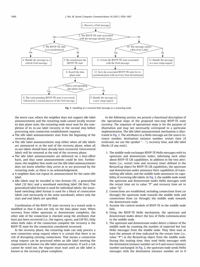
When a downstream node restarts, it recovers its RSVP-TE statefrom its upstream neighbor by receiving the Path messages carry-ing the Recovery Label to provide the most recently received labelvalue in the corresponding Resv messages. Handling of a receivedPath message is defined in Section 9.5.2 in [10] and is modifiedin Section 4.5.2 in [12]. The modification is made to synchronizethe recovery of the RSVP-TE state in a transit node (i.e., a node thatis neither a non-ingress nor non-egress node), where the recoveryfrom upstream and downstream neighbors must be co-ordinated.The RSVP-TE state in a transit node is considered ‘‘re-synchro-nized’’ when its recovery from both upstream and downstreamneighbors is completed as defined in Section 4.5.2 of [12]. The han-dling procedure is illustrated in Fig. 1. Note that new connectionsetup requests could potentially be processed during recovery,for example, in steps 9 or 13 in Fig. 1.
When an upstream node restarts, it recovers its RSVP-TE statefrom its downstream neighbor by receiving RecoveryPath and re-transmitted Resv messages. The RecoveryPath messages copy backthe Path messages (excluding message ID and a few other objects)
that were previously sent out from the restarting node. Beforeusing RecoveryPath messages, the restarting node and its down-stream neighbor must mutually agree upon their use in the Hellomechanism [12]. The restarting node re-synchronizes its RSVP-TEstate related to a data plane connection after it receives the Pathmessage with the Recovery Label from its upstream neighbor withrespect to the connection and corresponding RecoveryPath messagefrom its downstream neighbor. Upon synchronization, the restart-ing node must send a triggered Path message to its downstreamneighbor, which in turn triggers a re-transmitted Resv messagefrom its downstream neighbor. After receiving the re-transmittedResv message, the restarting node recovers its state that representsthe cross-connect for the connection.
3.3. Related work on control plane failure recovery in the GMPLScontrol plane
Control plane failure recovery has been studied architecturally,analytically, and experimentally for different protocols in theGMPLS control plane. GR has been applied to GMPLS routing andsignaling protocols [2]. The details of the architectures and specifi-cations of the GR for different protocols are defined by the IETF(see, for example, [20,21]). An overview of RSVP-TE GR was givenin [37]. The performance of RSVP-TE GR was evaluated using ana-lytical models and simulations [38–40]. The performance of gen-eral RSVP or RSVP-TE was evaluated with a focus on messageloss [41,42], processing and bandwidth requirements [42,43], sca-lability [36,44], and connection setup time [45]. We presented theconcept of RSVP-TE GR enhancement in [46]. Our previous work onthe enhancements of a signaling protocol (the Constraint-basedRouting Label Distribution Protocol (CR-LDP)) was presented in[47,48].
4. Proposal of a two-step RSVP-TE state recovery
4.1. Description of a two-step RSVP-TE state recovery
In standard RSVP-TE GR, requests for connection setup and re-moval are processed as soon as the restart phase completes. Inthe recovery phase, RSVP-TE state recovery messages are mixedwith messages for connection setup and removal. In this way,the delay for connection setup and removal is reduced. However,if the data plane state cannot be recovered first, new connectionscould accidentally take in-use resources and disrupt existingconnections.
We propose to recover the RSVP-TE state in two steps, wherethe first step is to recover the RSVP-TE state in which labels wereidle before a control plane failure, and the second step is to recoverthe complete RSVP-TE state. The first step is realized as an exten-sion to the RSVP-TE Hello mechanism, where a neighbor an-nounces the idle labels to the restarting node with respect to theRSVP session. The second step follows RSVP-TE GR, except that ver-ification with the locally recovered data plane state becomesoptional.
Our extensions to the RSVP-TE Hello mechanism for idle labelannouncement are as follows:
� The capability of transmitting and receiving idle labelannouncements should be carried by the capability object (i.e.,the RestartCap object) in Hello messages. The restarting nodemust tell its neighbor of its desire to receive idle labelannouncements or not. If the restarting node can locally recoverits data plane state, it should tell its neighbor that it does notwant to receive idle label announcements. A neighbor must tellthe restarting node whether it is able to provide idle labels. In
1. Receive a Path message
2. The RSVP-TE state associatedwith the message already exists
Yes
11. Create the RSVP-TE state associatedwith the Path message
No
10. The message carriesa Recovery Label
Yes No
4. Handle the message as a refresh Path message
3. The RSVP-TE stateis re-synchronized
Yes No
5. Re-synchronize the RSVP-TE state
13. Handle the message as a new setup request
8. The corresponding RSVP-TE state is recovered, followed by a normal process of the Path message
7. Find a correspondingdata plane state
Yes
9. Handle the message as a new setup request
No
6. Search the data plane state
12. Save the associated RSVP-TE state for re-synchronization with recovery from downstream
Fig. 1. Handling of a received Path message at a restarting node.
1960 J. Wu, M. Savoie / Computer Communications 34 (2011) 1956–1967
the worst case, where the neighbor does not support idle labelannouncements and the restarting node cannot locally recoverits date plane state, the restarting node must wait for the com-pletion of its in-use label recovery in the second step beforeprocessing new connection establishment requests.� The idle label announcements start from the beginning of the
recovery phase.� The idle label announcements stop either when all idle labels
are announced or at the end of the recovery phase, when allin-use labels should have already been recovered. Unrecoveredlabels will be removed at the end of the recovery phase.� The idle label announcements are delivered on a best-effort
basis, and thus some announcements could be lost. Further-more, the neighbor that sends out the idle label announcementsdoes not know whether they arrive at or are processed by therestarting node, as there is no acknowledgement.� A neighbor does not repeat its announcement for the same idle
label.� Idle labels may be encoded in two formats [9]: a generalized
label (32 bits) and a waveband switching label (96 bits). Thegeneralized label format is used for individual labels; the wave-band switching label format is used for a block of consecutivelabels (not necessarily in the same waveband), where only thestart and end labels are specified.
Coordination of the RSVP-TE state recovery in a transit node ismodified so that it does not rely on the data plane state. Whenrecovery from either upstream or downstream completes, theother side of the connection is checked using the attributes thathave just been recovered (i.e., the ingress, egress, and LSP ID). Onlywhen both sides of the connection complete the recovery is theRSVP-TE state for the connection considered recovered.
In the recovery phase, the restarting node can only process anew connection setup request when it is certain that there is norisk of disrupting existing connections. That means a connectionsetup request can be processed when an idle label meeting therequirement is known via idle label announcements. If such a riskcannot be ruled out, the request must wait until an idle label isknown or the recovery phase completes.
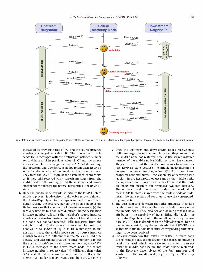
In the following section, we present a functional description ofthe operational steps of the proposed two-step RSVP-TE staterecovery. The sequence of operational steps is for the purpose ofillustration and may not necessarily correspond to a particularimplementation. The idle label announcement mechanism is illus-trated in Fig. 2. The attributes in a Hello message are the source in-stance number, destination instance number, restart time (ifirrelevant, we use the symbol ‘‘. . .’’), recovery time, and idle labelblocks (if any exist).
1. The middle node exchanges RSVP-TE Hello messages with itsupstream and downstream nodes, informing each otherabout RSVP-TE GR capabilities. In addition to the two attri-butes (i.e., restart time and recovery time) defined in theRestartCap object for RSVP-TE GR capabilities, the upstreamand downstream nodes announce their capabilities of trans-mitting idle labels, and the middle node announces its capa-bility of receiving idle labels. In Fig. 2, the middle node sendsthe upstream and downstream nodes Hello messages withthe restart time set to value ‘‘P’’ and recovery time set tovalue ‘‘Q’’.
2. Connections are established, including connections from (orthrough) the upstream node towards the middle node andconnections from (or through) the middle node towardsthe downstream node.
3. Assume the control module of RSVP-TE in the middle nodefails.
4. Using the RSVP-TE Hello mechanism, the upstream anddownstream nodes detect the loss of Hello communicationto the middle node.
5. The upstream and downstream nodes detect a failure of themiddle node by counting the number of expected but lostHello messages from the middle node. They then wait atleast the amount of time indicated by the restart time (i.e.,value ‘‘P’’) in the RestartCap object from the middle node.During this waiting time, they send Hello messages withthe destination instance number set to 0 and source instancenumber unchanged. In Fig. 2, the upstream node sends Hellomessages with the destination instance number set to 0
Upstream Neighbour
Failed/Restarting Node
Downstream Neighbour
Hello (A,B,P,Q) Hello (G,F,P,Q)
Hello (B,A,...,...)Hello (F,G,...,...)
Hello (B,0,...,…)
Hello Tim
eout Interval
Restart Period
Hello (F,0,...,…)
Hello (B,0,...,…)Hello (F,0,...,…)
Hello (C≠A,B,P,Q≠0)
Hello (B,C,...,…, Idle Label Block 1)
Hello (H≠G,F,P,Q≠0)
Node fails
Restart completes
Resv
Path (Recovery Label=X)
Hello (B,C,...,…, Idle Label Block 2)
RecoveryPath (Label=Y)
Resv
Path (Label=Y)
Hello (F,H,...,…,Idle Label Block 1)
Hello (F,H,...,…,Idle Label Block 2)
Time to C
omplete R
ecovery
Recovery completes
Recovery Period
Hello communication resumes
Fig. 2. Idle label announcements in the proposed RSVP-TE Hello mechanism. The timeline starts from the top and progresses towards the bottom. The timeline is not to scale.
J. Wu, M. Savoie / Computer Communications 34 (2011) 1956–1967 1961
instead of its previous value of ‘‘A’’ and the source instancenumber unchanged as value ‘‘B’’. The downstream nodesends Hello messages with the destination instance numberset to 0 instead of its previous value of ‘‘G’’ and the sourceinstance number unchanged as value ‘‘F’’. While waiting,the upstream and downstream nodes retain their RSVP-TEstate for the established connections that traverse them.They treat the RSVP-TE state of the established connectionsas if they still received RSVP refresh messages from themiddle node. In the waiting period, the upstream and down-stream nodes suppress the normal refreshing of the RSVP-TEstate.
6. Once the middle node restarts, it initiates the RSVP-TE staterecovery process. It advertises its allowable recovery time inthe RestartCap object to the upstream and downstreamnodes. During the recovery period, the middle node sendsHello messages that contain the following elements: (i) therecovery time set to a non-zero duration; (ii) the destinationinstance number reflecting the neighbor’s source instancenumber or destination instance number set to 0 if the mid-dle node has not yet received Hello messages from theneighbor; and (iii) the source instance number set to anew value. As shown in Fig. 2, in Hello messages to theupstream node, the middle node sets its source instancenumber to value ‘‘C’’ (different than the ‘‘A’’ value used pre-viously) and uses the destination instance number to reflectthe upstream node’s source instance number (i.e., value ‘‘B’’).In Hello messages to the downstream node, the sourceinstance number is set to value ‘‘H’’ (different than value‘‘G’’), and the destination instance number reflects thedownstream node’s source instance number (i.e., value ‘‘F’’).
7. Once the upstream and downstream nodes receive newHello messages from the middle node, they know thatthe middle node has restarted because the source instancenumber of the middle node’s Hello messages has changed.They also know that the middle node wants to recover itslost RSVP-TE state because the middle node indicates anon-zero recovery time (i.e., value ‘‘Q’’). From one of ourproposed new attributes – the capability of receiving idlelabels – in the RestartCap object sent by the middle node,the upstream and downstream nodes know that the mid-dle node can facilitate our proposed two-step recovery.The upstream and downstream nodes then mark all oftheir RSVP-TE states shared with the middle node as stale,retain the stale state, and continue to use the correspond-ing connections.
8. The upstream and downstream nodes announce their idlelabels shared with the middle node in Hello messages tothe middle node. They also set one of our proposed newattributes – the capability of transmitting idle labels – inthe RestartCap object sent to the middle node. They the ini-tiate RSVP-TE GR as described in the following steps. Duringthe recovery period, they do not refresh their RSVP-TE stateshared with the middle node until corresponding Path mes-sages have been received.
9. For each connection that travels from the upstream nodeto the middle node, the upstream node places its outgoinglabel (the label which was received in a Resv messagefrom the middle node before the middle node restarted)in the Recovery Label object of the Path message andsends it to the middle node, e.g., in Fig. 2, ‘‘RecoveryLabel = X’’.
1962 J. Wu, M. Savoie / Computer Communications 34 (2011) 1956–1967
10. In our example, the downstream node does not send a Pathmessage to the middle node because no connection travelsfrom the downstream node to the middle node. The down-stream node waits until it has received a Path message fromthe middle node to refresh the corresponding RSVP-TE statein the downstream node.
11. The middle node processes the received Path messageaccording to the procedure illustrated in Fig. 1. Assume themiddle node does not find the RSVP-TE state correspondingto the received Path message. The middle node therefore cre-ates an RSVP-TE state and waits for re-synchronization withthe downstream node for the created RSVP-TE state. Themiddle node sends a Resv message to the upstream nodeso that the upstream node can clear its stale flag for thelabel.
12. For each connection that travels from the middle node to thedownstream node, the downstream node places its incom-ing label (the label assigned by the downstream node andsent to the middle node in a Resv message before the middlenode restarted) in a RecoveryPath message and sends it tothe middle node, e.g., in Fig. 2, ‘‘Label = Y’’.
13. The middle node re-synchronizes its RSVP-TE state by asso-ciating its incoming and outgoing labels together for pass-through connections. Then, the middle node sends thedownstream node a Path message, e.g., in Fig. 2, ‘‘Label = Y’’.The downstream node clears its stale flag for the label.
14. The recovery period expires. The upstream node sends Path-Tear messages to the middle node for all stale labels. Thedownstream node sends ResvTear messages to the middlenode for all stale labels. The recovery is completed.
4.2. Processing of connection removal requests during the RSVP-TEstate recovery
In the recovery phase, the processing of connection removal re-quests must be coordinated with recovery of the related RSVP-TEstate. We present a generic scenario in which a restarting node isan intermediate node of the connection to be removed. The restart-ing node always releases the resources used by the connection
Table 2Process procedure of received connection removal messages at a restarting node.
The RSVP-TE messagearrived at therestarting node
Is the recovery with theupstream neighbor completedfor the connection?
Is the recovery with thedownstream neighborcompleted for the connect
PathTear Yes YesPathTear Yes No
PathTear No Yes
PathTear No No
ResvTear Yes YesResvTear Yes No
ResvTear No Yes
ResvTear No No
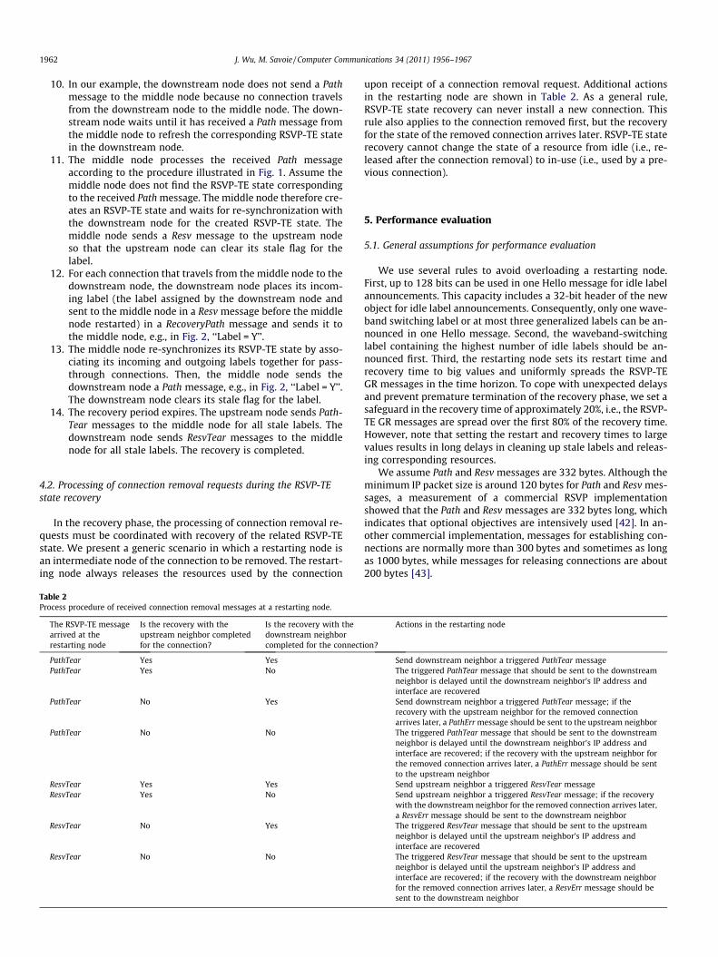
upon receipt of a connection removal request. Additional actionsin the restarting node are shown in Table 2. As a general rule,RSVP-TE state recovery can never install a new connection. Thisrule also applies to the connection removed first, but the recoveryfor the state of the removed connection arrives later. RSVP-TE staterecovery cannot change the state of a resource from idle (i.e., re-leased after the connection removal) to in-use (i.e., used by a pre-vious connection).
5. Performance evaluation
5.1. General assumptions for performance evaluation
We use several rules to avoid overloading a restarting node.First, up to 128 bits can be used in one Hello message for idle labelannouncements. This capacity includes a 32-bit header of the newobject for idle label announcements. Consequently, only one wave-band switching label or at most three generalized labels can be an-nounced in one Hello message. Second, the waveband-switchinglabel containing the highest number of idle labels should be an-nounced first. Third, the restarting node sets its restart time andrecovery time to big values and uniformly spreads the RSVP-TEGR messages in the time horizon. To cope with unexpected delaysand prevent premature termination of the recovery phase, we set asafeguard in the recovery time of approximately 20%, i.e., the RSVP-TE GR messages are spread over the first 80% of the recovery time.However, note that setting the restart and recovery times to largevalues results in long delays in cleaning up stale labels and releas-ing corresponding resources.
We assume Path and Resv messages are 332 bytes. Although theminimum IP packet size is around 120 bytes for Path and Resv mes-sages, a measurement of a commercial RSVP implementationshowed that the Path and Resv messages are 332 bytes long, whichindicates that optional objectives are intensively used [42]. In an-other commercial implementation, messages for establishing con-nections are normally more than 300 bytes and sometimes as longas 1000 bytes, while messages for releasing connections are about200 bytes [43].
ion?
Actions in the restarting node
Send downstream neighbor a triggered PathTear messageThe triggered PathTear message that should be sent to the downstreamneighbor is delayed until the downstream neighbor’s IP address andinterface are recoveredSend downstream neighbor a triggered PathTear message; if therecovery with the upstream neighbor for the removed connectionarrives later, a PathErr message should be sent to the upstream neighborThe triggered PathTear message that should be sent to the downstreamneighbor is delayed until the downstream neighbor’s IP address andinterface are recovered; if the recovery with the upstream neighbor forthe removed connection arrives later, a PathErr message should be sentto the upstream neighborSend upstream neighbor a triggered ResvTear messageSend upstream neighbor a triggered ResvTear message; if the recoverywith the downstream neighbor for the removed connection arrives later,a ResvErr message should be sent to the downstream neighborThe triggered ResvTear message that should be sent to the upstreamneighbor is delayed until the upstream neighbor’s IP address andinterface are recoveredThe triggered ResvTear message that should be sent to the upstreamneighbor is delayed until the upstream neighbor’s IP address andinterface are recovered; if the recovery with the downstream neighborfor the removed connection arrives later, a ResvErr message should besent to the downstream neighbor
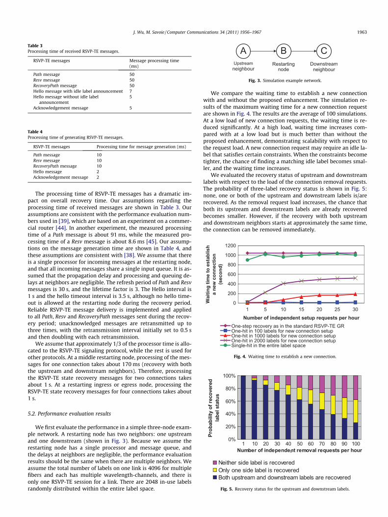
Fig. 5. Recovery status for the upstream and downstream labels.
Fig. 4. Waiting time to establish a new connection.
Fig. 3. Simulation example network.
Table 3Processing time of received RSVP-TE messages.
RSVP-TE messages Message processing time(ms)
Path message 50Resv message 50RecoveryPath message 50Hello message with idle label announcement 7Hello message without idle label
announcement5
Acknowledgement message 5
Table 4Processing time of generating RSVP-TE messages.
RSVP-TE messages Processing time for message generation (ms)
Path message 10Resv message 10RecoveryPath message 10Hello message 2Acknowledgement message 2
J. Wu, M. Savoie / Computer Communications 34 (2011) 1956–1967 1963
The processing time of RSVP-TE messages has a dramatic im-pact on overall recovery time. Our assumptions regarding theprocessing time of received messages are shown in Table 3. Ourassumptions are consistent with the performance evaluation num-bers used in [39], which are based on an experiment on a commer-cial router [44]. In another experiment, the measured processingtime of a Path message is about 91 ms, while the measured pro-cessing time of a Resv message is about 8.6 ms [45]. Our assump-tions on the message generation time are shown in Table 4, andthese assumptions are consistent with [38]. We assume that thereis a single processor for incoming messages at the restarting node,and that all incoming messages share a single input queue. It is as-sumed that the propagation delay and processing and queuing de-lays at neighbors are negligible. The refresh period of Path and Resvmessages is 30 s, and the lifetime factor is 3. The Hello interval is1 s and the hello timeout interval is 3.5 s, although no hello time-out is allowed at the restarting node during the recovery period.Reliable RSVP-TE message delivery is implemented and appliedto all Path, Resv and RecoveryPath messages sent during the recov-ery period; unacknowledged messages are retransmitted up tothree times, with the retransmission interval initially set to 0.5 sand then doubling with each retransmission.
We assume that approximately 1/3 of the processor time is allo-cated to the RSVP-TE signaling protocol, while the rest is used forother protocols. At a middle restarting node, processing of the mes-sages for one connection takes about 170 ms (recovery with boththe upstream and downstream neighbors). Therefore, processingthe RSVP-TE state recovery messages for two connections takesabout 1 s. At a restarting ingress or egress node, processing theRSVP-TE state recovery messages for four connections takes about1 s.
5.2. Performance evaluation results
We first evaluate the performance in a simple three-node exam-ple network. A restarting node has two neighbors: one upstreamand one downstream (shown in Fig. 3). Because we assume therestarting node has a single processor and message queue, andthe delays at neighbors are negligible, the performance evaluationresults should be the same when there are multiple neighbors. Weassume the total number of labels on one link is 4096 for multiplefibers and each has multiple wavelength-channels, and there isonly one RSVP-TE session for a link. There are 2048 in-use labelsrandomly distributed within the entire label space.
We compare the waiting time to establish a new connectionwith and without the proposed enhancement. The simulation re-sults of the maximum waiting time for a new connection requestare shown in Fig. 4. The results are the average of 100 simulations.At a low load of new connection requests, the waiting time is re-duced significantly. At a high load, waiting time increases com-pared with at a low load but is much better than without theproposed enhancement, demonstrating scalability with respect tothe request load. A new connection request may require an idle la-bel that satisfies certain constraints. When the constraints becometighter, the chance of finding a matching idle label becomes smal-ler, and the waiting time increases.
We evaluated the recovery status of upstream and downstreamlabels with respect to the load of the connection removal requests.The probability of three-label recovery status is shown in Fig. 5:none, one or both of the upstream and downstream labels is/arerecovered. As the removal request load increases, the chance thatboth its upstream and downstream labels are already recoveredbecomes smaller. However, if the recovery with both upstreamand downstream neighbors starts at approximately the same time,the connection can be removed immediately.
0 100 200 3000
0.2
0.4
0.6
0.8
1
Request Completion Time (Second)
Cum
ulat
ive
Dis
tribu
tion
Func
tion
Standard RSVP-TE GRWith our proposal (single suitable label)With our proposal (1-in-10 suitable label)
0 100 200 300 400 5000
0.2
0.4
0.6
0.8
1
Request Completion Time (Second)
Cum
ulat
ive
Dis
tribu
tion
Func
tion
Standard RSVP-TE GRWith our proposal (single suitable label)With our proposal (1-in-10 suitable label)
A
B
Fig. 7. Cumulative distribution function of the request completion time (nomessage loss), (a) NSFNET; (b) Pan-European network.
13
2
11
9
8
10
76
5
41
0121
0
2
34
5
6
8
910
11
12
13
1415
1617
1819
20
73
139
8
54
0
12
1
2
3
4
5
6
7
8
9
10
111213
14
151617
18
19
2023
25
21
24
2731
34
30
2926 28
33
32
017
18
2
3
1
6
7
11
1516
1410
1922
20 21
22
23
24
25
26
27 36
3537
38
39 40 41
42
43 4544
5049
48
47
46
58
5756
55
54
53
52
51
5960
B
A
Fig. 6. Example networks, (a) NSFNET with 14 nodes and 21 links; (b) Pan-European network with 28 nodes and 61 links.
1964 J. Wu, M. Savoie / Computer Communications 34 (2011) 1956–1967
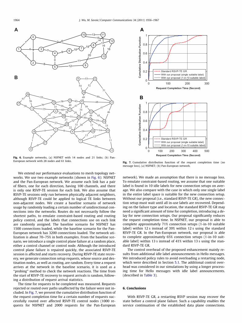
We extend our performance evaluations to mesh topology net-works. We use two example networks (shown in Fig. 6): NSFNETand the Pan-European network. We assume each link has a pairof fibers, one for each direction, having 100 channels, and thereis only one RSVP-TE session for each link. We also assume thatRSVP-TE sessions only run between physically adjacent neighbors,although RSVP-TE could be applied to logical TE links betweennon-adjacent nodes. We create a baseline scenario of networkusage by randomly loading a certain number of unidirectional con-nections into the networks. Routes do not necessarily follow theshortest paths, to emulate constraint-based routing and routingpolicy control, and the labels that connections use on each linkare randomly assigned. The baseline scenario for NSFNET has1500 connections loaded, while the baseline scenario for the Pan-European network has 3200 connections loaded. The network uti-lization is about 70–75% in both examples. From the baseline sce-nario, we introduce a single control plane failure at a random place,either a control channel or control node. Although the introducedcontrol plane failure is repaired quickly, the associated RSVP-TEsession is affected and starts recovery. During RSVP-TE state recov-ery, we generate connection setup requests, whose source and des-tination nodes, as well as routing, are random. Every time a requestarrives at the network in the baseline scenario, it is used as a‘‘probing’’ method to check the network reactions. The time fromthe start of RSVP-TE recovery to request arrivals is random, follow-ing a distribution of request arrival statistics.
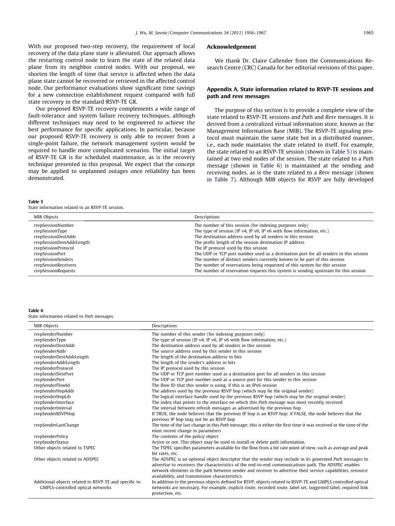
The time for requests to be completed was measured. Requestsrejected or routed over paths unaffected by the failure were not in-cluded. In Fig. 7, we present the cumulative distribution function ofthe request completion time for a certain number of requests suc-cessfully routed over affected RSVP-TE control nodes (1000 re-quests for NSFNET and 2000 requests for the Pan-European
network). We made an assumption that there is no message loss.To emulate constraint-based routing, we assume that one suitablelabel is found in 10 idle labels for new connection setups on aver-age. We also compare with the case in which only one single labelin the entire label space is suitable for the new connection setup.Without our proposal (i.e., standard RSVP-TE GR), the new connec-tion setup must wait until all in-use labels are recovered. Depend-ing on the failure type and location, the standard RSVP-TE GR mayneed a significant amount of time for completion, introducing a de-lay for new connection setups. Our proposal significantly reducesthe request completion time. In NSFNET, our proposal is able tocomplete approximately 71% connection setups (1-in-10 suitablelabel) within 12 s instead of 39% within 12 s using the standardRSVP-TE GR. In the Pan-European network, our proposal is ableto complete approximately 65% connection setups (1-in-10 suit-able label) within 13 s instead of 41% within 13 s using the stan-dard RSVP-TE GR.
The control overhead of the proposed enhancement mainly re-sults from additional idle label announcements in Hello messages.We introduced policy rules to avoid overloading a restarting node,which were described in Section 5.1. The additional control over-head was considered in our simulations by using a longer process-ing time for Hello messages with idle label announcements.(described in Table 3).
6. Conclusions
With RSVP-TE GR, a restarting RSVP session may recover thestate before a control plane failure. Such a capability enables theservice continuation of the established data plane connections.
J. Wu, M. Savoie / Computer Communications 34 (2011) 1956–1967 1965
With our proposed two-step recovery, the requirement of localrecovery of the data plane state is alleviated. Our approach allowsthe restarting control node to learn the state of the related dataplane from its neighbor control nodes. With our proposal, weshorten the length of time that service is affected when the dataplane state cannot be recovered or retrieved in the affected controlnode. Our performance evaluations show significant time savingsfor a new connection establishment request compared with fullstate recovery in the standard RSVP-TE GR.
Our proposed RSVP-TE recovery complements a wide range offault-tolerance and system failure recovery techniques, althoughdifferent techniques may need to be engineered to achieve thebest performance for specific applications. In particular, becauseour proposed RSVP-TE recovery is only able to recover from asingle-point failure, the network management system would berequired to handle more complicated scenarios. The initial targetof RSVP-TE GR is for scheduled maintenance, as is the recoverytechnique presented in this proposal. We expect that the conceptmay be applied to unplanned outages once reliability has beendemonstrated.
Table 6State information related to Path messages.
MIB Objects Descriptions
rsvpSenderNumber The number of this senderrsvpSenderType The type of session (IP v4,rsvpSenderDestAddr The destination address usrsvpSenderAddr The source address used brsvpSenderDestAddrLength The length of the destinatirsvpSenderAddrLength The length of the sender’srsvpSenderProtocol The IP protocol used by thrsvpSenderDestPort The UDP or TCP port numbrsvpSenderPort The UDP or TCP port numbrsvpSenderFlowId The flow ID that this sendersvpSenderHopAddr The address used by the prrsvpSenderHopLih The logical interface handlrsvpSenderInterface The index that points to thrsvpSenderInterval The interval between refrersvpSenderRSVPHop If TRUE, the node believes
previous IP hop may not brsvpSenderLastChange The time of the last change
most recent change in pararsvpSenderPolicy The contents of the policyrsvpSenderStatus Active or not. This object mOther objects related to TSPEC The TSPEC specifies parame
bit rates, etc.Other objects related to ADSPEC The ADSPEC is an optional
advertise to receivers the cnetwork elements in the pavailability, and transmissi
Additional objects related to RSVP-TE and specific toGMPLS-controlled optical networks
In addition to the previousnetworks are necessary. Foprotection, etc.
Table 5State information related to an RSVP-TE session.
MIB Objects Descr
rsvpSessionNumber The nrsvpSessionType The tyrsvpSessionDestAddr The drsvpSessionDestAddrLength The prsvpSessionProtocol The IPrsvpSessionPort The UrsvpSessionSenders The nrsvpSessionReceivers The nrsvpSessionRequests The n
Acknowledgement
We thank Dr. Claire Callender from the Communications Re-search Centre (CRC) Canada for her editorial revisions of this paper.
Appendix A. State information related to RSVP-TE sessions andpath and resv messages
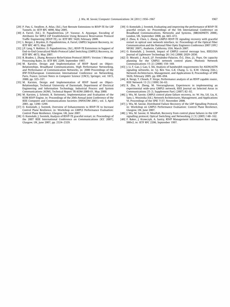
The purpose of this section is to provide a complete view of thestate related to RSVP-TE sessions and Path and Resv messages. It isderived from a centralized virtual information store, known as theManagement Information Base (MIB). The RSVP-TE signaling pro-tocol must maintain the same state but in a distributed manner,i.e., each node maintains the state related to itself. For example,the state related to an RSVP-TE session (shown in Table 5) is main-tained at two end nodes of the session. The state related to a Pathmessage (shown in Table 6) is maintained at the sending andreceiving nodes, as is the state related to a Resv message (shownin Table 7). Although MIB objects for RSVP are fully developed
(for indexing purposes only)IP v6, IP v6 with flow information, etc.)ed by all senders in this sessiony this sender in this sessionon address in bitsaddress in bitsis sessioner used as a destination port for all senders in this sessioner used as a source port for this sender in this sessionr is using, if this is an IPv6 sessionevious RSVP hop (which may be the original sender)
e used by the previous RSVP hop (which may be the original sender)e interface on which this Path message was most recently receivedsh messages as advertised by the previous hopthat the previous IP hop is an RSVP hop; if FALSE, the node believes that thee an RSVP hopin this Path message; this is either the first time it was received or the time of themeters
objectay be used to install or delete path information.ters available for the flow from a bit rate point of view, such as average and peak
object descriptor that the sender may include in its generated Path messages toharacteristics of the end-to-end communications path. The ADSPEC enablesath between sender and receiver to advertise their service capabilities, resourceon characteristics.objects defined for RSVP, objects related to RSVP-TE and GMPLS controlled opticalr example, explicit route, recorded route, label set, suggested label, required link
iptions
umber of this session (for indexing purposes only)pe of session (IP v4, IP v6, IP v6 with flow information, etc.)
estination address used by all senders in this sessionrefix length of the session destination IP address
protocol used by this sessionDP or TCP port number used as a destination port for all senders in this sessionumber of distinct senders currently known to be part of this sessionumber of reservations being requested of this system for this sessionumber of reservation requests this system is sending upstream for this session
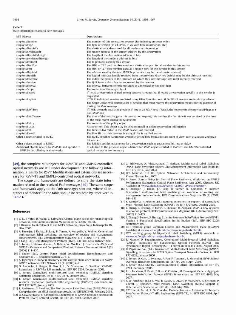
Table 7State information related to Resv messages.
MIB Objects Descriptions
rsvpResvNumber The number of this reservation request (for indexing purposes only)rsvpResvType The type of session (IP v4, IP v6, IP v6 with flow information, etc.)rsvpResvDestAddr The destination address used by all senders in this sessionrsvpResvSenderAddr The source address of the sender selected by this reservationrsvpResvDestAddrLength The length of the destination address in bitsrsvpResvSenderAddrLength The length of the sender’s address in bitsrsvpResvProtocol The IP protocol used by this sessionrsvpResvDestPort The UDP or TCP port number used as a destination port for all senders in this sessionrsvpResvPort The UDP or TCP port number used as a source port for this sender in this sessionrsvpResvHopAddr The address used by the next RSVP hop (which may be the ultimate receiver)rsvpResvHopLih The logical interface handle received from the previous RSVP hop (which may be the ultimate receiver)rsvpResvInterface The index that points to the interface on which this Resv message was most recently receivedrsvpResvService The QoS Service classification requested by the receiverrsvpResvInterval The interval between refresh messages as advertised by the next hoprsvpResvScope The contents of the scope objectrsvpResvShared If TRUE, a reservation shared among senders is requested; if FALSE, a reservation specific to this sender is
requestedrsvpResvExplicit If TRUE, individual senders are listed using Filter Specifications; if FALSE, all senders are implicitly selected.
The Scope Object will contain a list of senders that must receive this reservation request for the purpose ofrouting the Resv message
rsvpResvRSVPHop If TRUE, the node treats the previous IP hop as an RSVP hop; if FALSE, the node treats the previous IP hop as anon-RSVP hop
rsvpResvLastChange The time of the last change in this reservation request; this is either the first time it was received or the timeof the most recent change in parameters
rsvpResvPolicy The contents of the policy objectrsvpResvStatus Active or not. This object may be used to install or delete reservation informationrsvpResvTTL The time-to-live value in the RSVP header last receivedrsvpResvFlowId The flow ID that this receiver is using if this is an IPv6 sessionOther objects related to TSPEC The TSPEC specifies parameters available for the flow from a bit rate point of view, such as average and peak
bit rate, etc.Other objects related to RSPEC The RSPEC specifies parameters for a reservation, such as guaranteed bit rate or delayAdditional objects related to RSVP-TE and specific to
GMPLS-controlled optical networksIn addition to the previous objects defined for RSVP, objects related to RSVP-TE and GMPLS-controlledoptical networks are necessary
1966 J. Wu, M. Savoie / Computer Communications 34 (2011) 1956–1967
[49], the complete MIB objects for RSVP-TE and GMPLS-controlledoptical networks are still under development. The following infor-mation is mainly for RSVP. Modifications and extensions are neces-sary for RSVP-TE and GMPLS-controlled optical networks.
The scope and framework are defined to store the state infor-mation related to the received Path messages [49]. The same scopeand framework apply to the Path messages sent out, where all in-stances of ‘‘sender’’ in the table should be replaced by ‘‘receiver’’ inTable 6.
References
[1] G. Li, J. Yates, D. Wang, C. Kalmanek, Control plane design for reliable opticalnetworks, IEEE Communications Magazine 40 (2) (2002) 90–96.
[2] I. Hussain, Fault-Tolerant IP and MPLS Networks, Cisco Press, Indianapolis, IN,USA, 2005.
[3] A. Banerjee, J. Drake, J.P. Lang, B. Turner, K. Kompella, Y. Rekhter, Generalizedmultiprotocol label switching: an overview of routing and managementenhancements, IEEE Communications Magazine 39 (1) (2001) 144–150.
[4] J. Lang (Ed.), Link Management Protocol (LMP), IETF RFC 4204, October 2005.[5] S. Tomic, B. Statovci-Halimi, A. Halimi, W. Muellner, J. Fruehwirth, ASON and
GMPLS – Overview and Comparison, Photonic Network Communications 7 (2)(2004) 111–130.
[6] J. Sadler (Ed.), Control Plane Initial Establishment, Reconfiguration andRecovery, ITU-T Recommendation G.7716.
[7] A. Jajszczyk, P. Rozycki, Recovery of the control plane after failures in ASON/GMPLS networks, IEEE Network 20 (1) (2006) 4–7.
[8] D. Awduche, L. Berger, D. Gan, T. Li, V. Srinivasan, G. Swallow, RSVP-TE:Extensions to RSVP for LSP tunnels, in: IETF RFC 3209, December 2001.
[9] L. Berger, Generalized multi-protocol label switching (GMPLS) signalingfunctional description, in: IETF RFC 3471, January 2003.
[10] L. Berger, Generalized multi-protocol label switching (GMPLS) signalingresource reservation protocol-traffic engineering (RSVP-TE) extensions, in:IETF RFC 3473, January 2003.
[11] L. Andersson, G. Swallow, The Multiprotocol Label Switching (MPLS) WorkingGroup decision on MPLS signaling protocols, in: IETF RFC 3468, February 2003.
[12] A. Satyanarayana, R. Rahman (Ed.), Extensions to GMPLS Resource ReservationProtocol (RSVP) Graceful Restart, in: IETF RFC 5063, October 2007.
[13] C. Srinivasan, A. Viswanathan, T. Nadeau, Multiprotocol Label Switching(MPLS) Label Switching Router (LSR) Management Information Base (MIB), in:IETF RFC 3813, June 2004.
[14] H.T. Mouftah, P.H. Ho, Optical Networks: Architecture and Survivability,Kluwer Boston, Inc., 2002.
[15] A. Farrel, Standardising for Control Plane Resilience, Workshop on GMPLSPerformance Evaluation: Control Plane Resilience, June 2007, Glasgow, UK.Available at <www.olddog.co.uk/Farrel-ICC2007-CPResilience.ppt>.
[16] A. Banerjee, J. Drake, J.P. Lang, B. Turner, K. Kompella, Y. Rekhter,Generalized multiprotocol label switching: an overview of routing andmanagement enhancements, IEEE Communications Magazine 39 (1) (2001)144–150.
[17] K. Kompella, Y. Rekhter (Ed.), Routing Extensions in Support of GeneralizedMulti-Protocol Label Switching (GMPLS), in: IETF RFC 4202, October 2005.
[18] L. Zhang, S. Deering, D. Estrin, S. Shenker, D. Zappala, RSVP: a new resourcereservation protocol, IEEE Communications Magazine 40 (5, Anniversary Part)(2002) 116–127.
[19] L. Zhang, S. Berson, S. Herzog, S. Jamin, Resource ReSerVation Protocol (RSVP):Version 1 Functional Specification, in: R. Braden (Ed.), IETF RFC 2205,September 1997.
[20] IETF working group Common Control and Measurement Plane (CCAMP).Available at <www.ietf.org/html.charters/ccamp-charter.html>.
[21] IETF working group Multiprotocol Label Switching (MPLS). Available at<www.ietf.org/html.charters/mpls-charter.html>.
[22] E. Mannie, D. Papadimitriou, Generalized Multi-Protocol Label Switching(GMPLS) Extensions for Synchronous Optical Network (SONET) andSynchronous Digital Hierarchy (SDH) Control, in: IETF RFC 4606, August 2006.
[23] D. Papadimitriou, (Ed.), Generalized Multi-Protocol Label Switching (GMPLS)Signalling Extensions for G.709 Optical Transport Networks Control, in: IETFRFC 4328, January 2006.
[24] L. Berger, D. Gan, G. Swallow, P. Pan, F. Tommasi, S. Molendini, RSVP RefreshOverhead Reduction Extensions, in: IETF RFC 2961, April 2001.
[25] L. Berger, (Ed.), GMPLS - Communication of Alarm Information, in: IETF RFC4783, December 2006.
[26] F. Le Faucheur, B. Davie, P. Bose, C. Christou, M. Davenport, Generic AggregateResource ReSerVation Protocol (RSVP) Reservations, in: IETF RFC 4860, May2007.
[27] F. Le Faucheur, (Ed.), L. Wu, B. Davie, S. Davari, P. Vaananen, R. Krishnan, P.Cheval, J. Heinanen, Multi-Protocol Label Switching (MPLS) Support ofDifferentiated Services, in: IETF RFC 3270, May 2002.
[28] C.Y. Lee, A. Farrel, S. De Cnodder, Exclude Routes – Extension to ResourceReserVation Protocol-Traffic Engineering (RSVP-TE), in: IETF RFC 4874, April2007.
J. Wu, M. Savoie / Computer Communications 34 (2011) 1956–1967 1967
[29] P. Pan, G. Swallow, A. Atlas, (Ed.), Fast Reroute Extensions to RSVP-TE for LSPTunnels, in: IETF RFC 4090, May 2005.
[30] A. Farrel, (Ed.), D. Papadimitriou, J.P. Vasseur, A. Ayyangar, Encoding ofAttributes for MPLS LSP Establishment Using Resource Reservation ProtocolTraffic Engineering (RSVP-TE), in: IETF RFC 5420, February 2009.
[31] L. Berger, I. Bryskin, D. Papadimitriou, A. Farrel, GMPLS Segment Recovery, in:IETF RFC 4873, May 2007.
[32] J.P. Lang, Y. Rekhter, D. Papadimitriou, (Ed.), RSVP-TE Extensions in Support ofEnd-to-End Generalized Multi-Protocol Label Switching (GMPLS) Recovery, in:IETF RFC 4872, May 2007.
[33] R. Braden, L. Zhang, Resource ReSerVation Protocol (RSVP): Version 1 MessageProcessing Rules, in: IETF RFC 2209, September 1997.
[34] M. Karsten, Design and Implementation of RSVP Based on Object-Relationships, Broadband Communications, High Performance Networking,and Performance of Communication Networks, in: 2000 Proceedings of theIFIP-TC6/European Commission International Conference on Networking,Paris, France, Lecture Notes in Computer Science (LNCS), Springer, vol. 1815,2000, pp. 325–337.
[35] M. Karsten, Design and Implementation of RSVP based on Object-Relationships, Technical University of Darmstadt, Department of ElectricalEngineering and Information Technology, Industrial Process and SystemCommunications (KOM), Technical Report TR-KOM-2000-01, May 2000.
[36] M. Karsten, J. Schmitt, R. Steinmetz, Implementation and Evaluation of theKOM RSVP Engine, in: Proceedings of the 20th Annual Joint Conference of theIEEE Computer and Communications Societies (INFOCOM 2001), vol. 3, April2001, pp. 1290–1299.
[37] O. Komolafe, J. Sventek, Overview of Enhancements to RSVP-TE to IncreaseControl Plane Resilience, in: Workshop on GMPLS Performance Evaluation:Control Plane Resilience, Glasgow, UK, June 2007.
[38] O. Komolafe, J. Sventek, Analysis of RSVP-TE graceful restart, in: Proceedings ofthe 2007 IEEE International Conference on Communications (ICC 2007),Glasgow, UK, June 2007, pp. 2324–2329.
[39] O. Komolafe, J. Sventek, Evaluating and improving the performance of RSVP-TEgraceful restart, in: Proceedings of the 5th International Conference onBroadband Communications, Networks and Systems, (BROADNETS 2008),London, UK, September 2008, pp. 665–672.
[40] Z. Zhou, K. Chen, L. Zheng, GMPLS RSVP-TE signaling recovery with gracefulrestart in optical user network interface, in: Proceedings of the Optical FiberCommunication and the National Fiber Optic Engineers Conference 2007 (OFC/NFOEC 2007), Anaheim, California, USA, March 2007.
[41] O. Komolafe, J. Sventek, Impact of GMPLS control message loss, IEEE/OSAJournal of Lightwave Technology 26 (14) (2008) 2029–2036.
[42] D. Morató, J. Aracil, J.P. Fernández-Palacios, Ó.G. Dios, J.L. Poyo, On capacityplanning for the GMPLS network control plane, Photonic NetworkCommunications 15 (2) (2008) 159–169.
[43] J. Li, F. Gao, J. Gao, S. Shi, Analysis of bandwidth requirements for ASON/ASTNsignaling networks, in: S.J. Ben Yoo, G.K. Chang, G. Li, K.W. Cheung (Eds.),Network Architectures, Management, and Applications II, Proceedings of SPIE5626, February 2005, pp. 690–694.
[44] A. Neogi, T. Chiueh, P. Stirpe, Performance analysis of an RSVP capable router,IEEE Network 13 (5) (1999) 56–63.
[45] X. Zhu, X. Zheng, M. Veeraraghavan, Experiences in implementing anexperimental wide-area GMPLS network, IEEE Journal on Selected Areas inCommunications 25 (3, Supplement Part) (2007) 82–92.
[46] J. Wu, M. Savoie, GMPLS control plane failure recovery, in: W. Hu, S.K. Liu, K.Sato, L. Wosinska (Ed.), Network Architectures, Management, and ApplicationsVI, Proceedings of the SPIE 7137, November 2008.
[47] J. Wu, M. Savoie, Distributed Failure Recovery of the LDP Signalling Protocol,in: Workshop on GMPLS Performance Evaluation: Control Plane Resilience,Glasgow, UK, June 2007.
[48] J. Wu, M. Savoie, H. Mouftah, Recovery from control plane failures in the LDPsignalling protocol, Optical Switching and Networking 2 (3) (2005) 148–162.
[49] F. Baker, J. Krawczyk, A. Sastry, RSVP Management Information Base usingSMIv2, in: IETF RFC 2206, September 1997.