redox potential measurements
TRANSCRIPT

8/8/2019 Redox Potential Measurements
http://slidepdf.com/reader/full/redox-potential-measurements 1/17
Redox Potential MeasurementsM.J. Vepraskas, J.L. Cox,
and Students of the Soil Science Dept.
NC State University
December 2002
Redox potential is an electrical measurement that shows the tendency of a soil
solution to transfer electrons to or from a reference electrode. From this
measurement we can estimate whether the soil is aerobic, anaerobic, and whether
chemical compounds such as Fe oxides or nitrate have been chemically reduced orare present in their oxidized forms (Vepraskas and Faulkner, 2001).
Making these measurements requires three basic pieces of equipment:
1. Platinum electrode
2. Voltmeter
3. Reference electrode
The basic set-up is shown below:
Pt wire
Referenceelectrode
Voltmeter
Soilsurface
Fig. 1. The Pt wire is buried into the soil to be in contact with the soilsolution. The reference electrode must also be in contact with the soil
solution. It has a ceramic tip which can be placed in the soil, or theelectrode can be placed in a salt bridge which is itself placed in the soil.Wires from both the Pt electrode and reference electrode are connected tothe voltmeter.

8/8/2019 Redox Potential Measurements
http://slidepdf.com/reader/full/redox-potential-measurements 2/17
Pt Electrodes
Platinum electrodes consist of a small piece of platinum wire that is soldered or fused towire made another metal. Platinum conducts electrons from the soil solution to the wireto which it is attached.
Platinum is used because it is assumed to be an inert metal. This means it does not giveup its own electrons (does not oxidize) to the wire or soil solution. Iron containingmaterials such as steel will oxidize themselves and send their own electrons to thevoltmeter. As a result the voltage we measure will not result solely from electrons beingtransferred to or from the soil.
Metals such as copper and aluminum will oxidize and also cannot be used for redoxpotential measurements. Stainless steel also may oxidize, but to a small extent, andshould not be used.
Reference Electrodes
Reference electrodes provide a standard redox reaction that will accept or give upelectrons to the soil solution. Two types of reference electrodes are in use: Ag/AgCl andCalomel.
Wire to voltmeter
Plastic case
Silver wire
AgCl salt
KCl solution
Ions in soil solution

8/8/2019 Redox Potential Measurements
http://slidepdf.com/reader/full/redox-potential-measurements 3/17
The Ag/AgCl electrode consists of a Ag metal wire and a AgCl salt. The basic reaction
is:
Ag Ag+ + e-
When the reaction goes to the right (Ag is oxidized) the electron is sent to the voltmeterand could be transmitted to the Pt wire to reduce chemicals in the soil solution if thevoltmeter were not present. If the reaction goes to the left then an electron comes fromthe voltmeter into the electrode.
The Ag and Ag+ are surrounded by a solution of KCl which maintains electricalneutrality. When the reaction above goes to the right, then a K+ is released to the soil
through the ceramic tip of the electrode. When the reaction goes to the left then a Cl-
anion is released through the ceramic tip.
Another type of reference electrode in common use is the calomel which contains Hg.The basic reaction is:
Hg Hg+ + e-
This electrode works the same as the Ag/AgCl.
Correction Factors
While both kinds of reference electrodes give reliable data, the voltages measured witheach electrode are interpreted slightly differently. It is for this reason that users mustknow which electrode they have.
The voltage measured in the field must be corrected to what would have been obtainedwith a different reference electrode, called the standard hydrogen reference electrode.This electrode cannot be used in the field, but our interpretations of redox potentialmeasurements are based on values determined with it. Therefore, all voltages measuredin the field with either the Ag/AgCl or calomel reference electrode have to be adjusted tothe value that would have been obtained had a standard hydrogen electrode been used.
The basic correction factors are:
Reference Electrode Correction Factor (mv)
Ag/AgCl in saturated KCl solution +200
Calomel +250
These correction factors are temperature dependent, but in most instances the effect of temperature is must less than the variability in the data for a given time. Therefore, in myopinion a temperature correction is not necessary unless very precise measurements arerequired.

8/8/2019 Redox Potential Measurements
http://slidepdf.com/reader/full/redox-potential-measurements 4/17
Formula for Converting Field Data to Redox Potential:
Field Voltage + Correction Factor = Redox Potential (Eh)
The symbol Eh or EH is used to indicate a voltage that has been corrected to what wouldhave been obtained with a standard hydrogen electrode.
Voltmeters
Voltmeters measure the amount of voltage needed to stop electrons from flowingbetween the Pt electrode and the reference electrodes. These meters should not let
electrons flow, otherwise stable readings will not be obtained.
Voltages produced by oxidation-reduction reactions are small, and range from +1 to –1volts (+1000 to –1000 mv). The voltmeter selected must be capable of measuring thesesmall voltages.
Two basic kinds of voltmeters are available: 1) laboratory grade Eh-pH meters and 2)commercial voltmeters. The lab grade meters are probably the most accurate of the twoto use. They can be expensive (>$300) and are preferred for research use.
Commercial voltmeters that measure millivolts seem to be adequate for routine use.
These are available for <$100.Sources of Equipment
The following supplies provide equipment. We have used all with good results or knowof others who have used these with good results.
Voltmeters
• Fisher Scientific Equipment Company
• Radio Shack
Reference Electrodes
• Fisher Scientific Equipment Company
• Jensen Instruments (2021 7th St., Tacoma, WA 98045; phone: 253-572-2659)
Platinum Electrodes
• Constructed in-house using one of the procedures shown below.
• Jensen Instruments: have constructed excellent electrodes in the past, but there
may be a delay in delivery of up to 9 months.

8/8/2019 Redox Potential Measurements
http://slidepdf.com/reader/full/redox-potential-measurements 5/17
• Louisiana State University: contact Dr. Wayne Hudnall. We have not used
electrodes from this laboratory but they have a good reputation.

8/8/2019 Redox Potential Measurements
http://slidepdf.com/reader/full/redox-potential-measurements 6/17
Brass Brazing
Rod
Any
desired
len th
1 mm
3.18mm (1/8 in.)
3 mm
Platinum Electrode Construction
For Redox Potential Measurements
Over the last 10 years, graduate students and technicians in the Soil Science
Department have constructed their own Pt electrodes using the proceduresdescribed below. The methods have evolved over time, and we expect will continue
to evolve. Two methods are described below. Method A uses epoxy to insulate and
seal the brass rod from the environment. Method B uses a rigid heat-shrink tubing
in place of the epoxy. Method A has been tested for a number of years and found to
be reliable. The epoxy is messy and therefore, Method B is easier to use. However,
our experience with Method B is limited and while we use it now, it is still being
evaluated.
Materials:
Method A: Insulate with Epoxy
1/8” diameter brass brazing rod (available at many welding supply companies)
18 gauge platinum wire (available from Fisher Scientific. Phone # 1-800-766-7000)
Batterns flux (available at many welding supply stores)
1/4” and 3/16” initial diameter adhesive-lined polyolefin heat-shrink tubing (available from McMaster-Carr
Supply @ www.mcmaster.com)
Marine-Tex brand waterproof epoxy (available from most hardware stores)
Propane torch with adjustable flame attachment (available from most hardware stores)
Heat-shrink hot air gun (available from McMaster-Carr Supply @ www.mcmaster.com)
18 gauge multi-stranded wire (order different colors for differentdepths etc. Also available from McMaster-Carr Supply. )
Latex gloves and a pair of heat resistant gloves for handling propanetorch.
Needle nose pliers
Sandpaper: 70 grain and 150 grain, 1 pack of each.
Soldering iron and solder.
Method B: Insulate with Rigid, Heat-Shrink Tubing*
Rigid Heat Shrink Tubing (available from McMaster-Carr Supply @www.mcmaster.com part # 72675K51)
*All other materials are the same as for Method A.
Fig. A (steps 1-3)
8/8/2019 Redox Potential Measurements
http://slidepdf.com/reader/full/redox-potential-measurements 7/17
18 gauge
Pt wire
inserted 1
mm into
brass rod
Heat with
torch until
melted
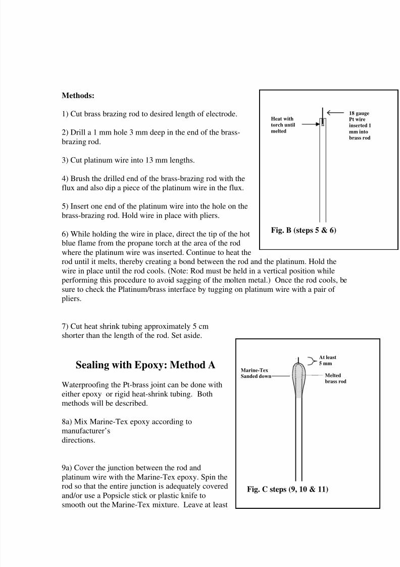
Methods:
1) Cut brass brazing rod to desired length of electrode.
2) Drill a 1 mm hole 3 mm deep in the end of the brass-brazing rod.
3) Cut platinum wire into 13 mm lengths.
4) Brush the drilled end of the brass-brazing rod with theflux and also dip a piece of the platinum wire in the flux.
5) Insert one end of the platinum wire into the hole on thebrass-brazing rod. Hold wire in place with pliers.
6) While holding the wire in place, direct the tip of the hotblue flame from the propane torch at the area of the rodwhere the platinum wire was inserted. Continue to heat therod until it melts, thereby creating a bond between the rod and the platinum. Hold thewire in place until the rod cools. (Note: Rod must be held in a vertical position whileperforming this procedure to avoid sagging of the molten metal.) Once the rod cools, besure to check the Platinum/brass interface by tugging on platinum wire with a pair of
pliers.
7) Cut heat shrink tubing approximately 5 cmshorter than the length of the rod. Set aside.
Sealing with Epoxy: Method A
Waterproofing the Pt-brass joint can be done with
either epoxy or rigid heat-shrink tubing. Bothmethods will be described.
8a) Mix Marine-Tex epoxy according tomanufacturer’sdirections.
9a) Cover the junction between the rod andplatinum wire with the Marine-Tex epoxy. Spin therod so that the entire junction is adequately covered
and/or use a Popsicle stick or plastic knife tosmooth out the Marine-Tex mixture. Leave at least
Marine-TexSanded down
At least
5 mm
Meltedbrass rod
Fig. C steps (9, 10 & 11)
Fig. B (steps 5 & 6)

8/8/2019 Redox Potential Measurements
http://slidepdf.com/reader/full/redox-potential-measurements 8/17
5 mm of the tip of the wire uncovered.
10a) Let the Marine-Tex set up until the Marine-Tex can be touched with a latex glovewithout adhering to the glove. Smooth the Marine-Tex with gloved fingers. Work theMarine-Tex down the rod until at least 5 mm of the Marine-Tex is thin enough for theheat shrink tubing to slide over. Leave excess Marine-Tex above this thinned area.
11a) After enough time has passed to allow the Marine-Tex epoxy to harden (24 hrs.) You must sand down theepoxied tip to smooth out any rough spots in the epoxy.Starting with a 60 or 70-grain sandpaper, smooth out thelarger bumps in the epoxy. Once the larger bumps havebeen smoothed use the 150-grain sandpaper to give theepoxy a smooth finish. Be sure to leave enough epoxy toallow for a watertight seal around the platinum wire.
12a) Slide a pre-cut piece of heat shrink tubing on the rodfrom the end without the platinum wire. Shove the tubingover at least 5 mm of the Marine-Tex.Starting with the end of the tubing that is in the Marine-Tex, shrink approximately 5 cm of the tubing.Slowly continue heating the rest of the tubing.Let harden.
Fig. D steps (12 & 13)
Heat Shrink tubing.First layer 4.76mm(3/16 in.) initialdiameter.
A second layer of 6.35mm (1/4in.)tubing will also beadded.
Leave 3-4cm of brass rod exposedfor attachment of mV leads.

8/8/2019 Redox Potential Measurements
http://slidepdf.com/reader/full/redox-potential-measurements 9/17
Sealing with Rigid Heat Shrink Tubing: Method B
8b) Next, slide a terminal insulator over the brass-Platinum interface, being careful to leave enough of the platinum exposed for proper contact with the soil.Then, using the heating gun, heat the insulator untilthe adhesive lining becomes liquefied and the insulatorshrinks around over the platinum. Allow insulator to cool.
9b) Slide a pre-cut piece of heat shrink tubing on the rodfrom the end without the platinum wire. Shove the tubingover at least 5 mm of the terminal insulator. Starting withthe platinum end of the tubing, shrink approximately5 cm of the tubing. Slowly continue heating the rest of the tubing. Let harden.
10b) Finish shrinking the rest of the tubing on the rod.
11) If needed, trim tubing from end of rod to leave enoughroom (approx. 5 cm) for the attachment of mV leads(18 gauge copper wire). For electrodes to be installedbetween 30 and 60 cm cut off approximately 6 feet of thecopper wire (use more copper wire for electrodes to beinstalled at deeper depths). Set aside.
12) With a knife or pair of electricians pliers strip about4 cm off the end of the wire. Wrap the 4 cm of exposedcopper wire around the exposed 5 cm of the brass rodand hold in place. Apply a liberal coat of solder all alongwhere the copper wire and brass rod meet and let cool.To check the soldered connection once the solder hascooled, tug on the copper wire gently. Apply a secondlayer of heat shrink tubing, making sure to cover the
soldered area where the m V leads were attached to thebrass rod and extend it approximately 15 cm up the
At least5 mm
Meltedbrass rod
Fig. E (step 8b)
Heat Shrink tubing.First layer 4.76mm(3/16 in.) initialdiameter.
A second layer of 6.35mm (1/4in.)tubing will also beadded.
Leave 3-4cm of brass rod exposedfor attachment of mV leads.
Heated insulator
Figure F. (steps 9, 10, 11)

8/8/2019 Redox Potential Measurements
http://slidepdf.com/reader/full/redox-potential-measurements 10/17
copper wire. You may apply a third layer of tubing
at the point where the brass rod and copper wire meetfor added protection and stability.
Be sure tocoverbrass/wireconnectionwith heatshrink tubing
18 gauge copperwire
Wrapexposed wirearound brassrod thensolder inplace.
Seal with
heat-shrink tubing
Fig. g (step 12)

8/8/2019 Redox Potential Measurements
http://slidepdf.com/reader/full/redox-potential-measurements 11/17
Procedure for Making Ferrous-Ferric solution (Light’s Solution) for
Oxidation-Reduction Potential Measurements and testing of electrodes.
Once constructed the electrodes have to be checked for accuracy. This is first done usinga solution of known and stable redox potential. The solution we have used was describedby Light (1972) and is prepared from scratch. The ingredients are shown below.
Composition: Concentration:
Ferrous ammonium sulfate39.21 g/l Fe (NH4)2 (SO4)2
. 6H200.100M
Ferric ammonium sulfate48.22 g/l FeNH4 (SO4)2
. 12H20 0.100M
Sulfuric Acid56.2 ml/l concentrated H2SO4
1.00 M
To test an electrode for accuracy:
First, scratch the platinum tips of each electrode with steel wool. Second, fill a beakerhalfway with the Light’s solution you have made. Fill a second beaker with tap water.Using a redox potential meter outfitted with a Ag, AgCl reference electrode you will takean mV reading of each electrode individually in both the buffer solution and in tap water.The buffer solution should read at +476mV (+/- 20 mV). The tap water reading will varyfrom the buffer reading but should not vary by more than 100 to 150 mV from otherelectrodes. If an electrode is varying more than 150 mV, there may be something wrongwith that electrode. Problems with electrode readout include; electrode not being watertight, platinum not having a good connection to brass rod, and copper wire not beingsoldered on correctly.

8/8/2019 Redox Potential Measurements
http://slidepdf.com/reader/full/redox-potential-measurements 12/17
Sample Results of Redox Electrode Test
Electrode#Light-soln
reading
DeionizedH20
reading
DeionizedH20
reading #2 Electrode#Light-soln
reading
DeionizedH20reading
DeionizedH20
reading #2
1 482 420 431 47 476 375 3862 480 383 387 48 444 410 4133 471 290 294 49 482 280 2834 478 250 254 50 478 370 3735 470 303 307 51 476 440 443
6 472 270 274 52 482 410 4137 465 360 364 53 480 350 3538 482 383 387 54 480 250 2539 482 441 445 55 481 360 36310 482 312 316 56 481 410 41311 482 367 371 57 482 260 26312 482 457 461 58 480 350 353
Installation of Redox Electrodes
• PVC braces (2-3) were constructed for each plot (see figures F&G).
• The stand was installed in a 10 cm diameter hole at approximately 45 cm depth.
• The braces were arrayed around the stand on three sides at approximately onemeter from the stand base. The braces were installed with a push probe so that thecross brace was about 15 cm above and parallel to the soil surface.
• The platinum-tipped electrodes were installed with a push probe at various depths.In a bucket, soil from the push-probed holes was mixed with water to form aslurry. The slurry was used to backfill the hole. The electrode platinum tip wasscraped before insertion into the soil and was then inserted through the slurry andinto undisturbed soil. The probes were secured to the brace with plastic cable ties.

8/8/2019 Redox Potential Measurements
http://slidepdf.com/reader/full/redox-potential-measurements 13/17

8/8/2019 Redox Potential Measurements
http://slidepdf.com/reader/full/redox-potential-measurements 14/17
Salt Bridge Construction
• Salt bridges, one per brace, were constructed and installed to aid redox potentialreadings.
• The salt bridges were constructed using 1-inch PVC, Potassium Chloride andAgar.
• The salt bridge is composed of:
(1) 25 – 30 g Agar and…(2) 250 mL of saturated KCL solution mixed with…
(3) 1L of boiling deionized water.
• These ingredients are allowed to cool until a pour able gel forms. This gel is thenpoured into the 1-inch PVC tubes until they are full and then allowed to cool. Thesalt bridges were installed using a 1-inch auger. A hole about 60 cm deep wasdrilled between the stand and the nearest brace. The hole was 30 to 50 cm fromthe brace and placed approximately in line with is center. 2 holes were drilledinto the PVC approximately 10 cm from the bottom of the pipe to allow the agarto come into contact with the soil. Then the salt bridge was installed into the pre-drilled hole.
1in. diameterPVC
Soil surface
Drilled holes in PVC
Salt Bridge Diagram
Bottom of PVC iscapped
Agar filled PVC pipe
10cm to holes

8/8/2019 Redox Potential Measurements
http://slidepdf.com/reader/full/redox-potential-measurements 15/17
APPENDIX B
Procedure for Making Thermocouples to
Measure Soil Temperature

8/8/2019 Redox Potential Measurements
http://slidepdf.com/reader/full/redox-potential-measurements 16/17
Procedure For Making Thermocouples To
Measure Soil Temperature
Materials
♦ Thermocouple Wire - Omega EXPP-T-20 (copper/constantan)
♦ Electrical Solder - 40% tin 60% lead (rosin core)
♦ 3/4” Schedule 40 PVC pipe
♦ 3/4” Schedule 40 PVC couple
♦ 3/4” Schedule 40 PVC end cap
♦ #3 rubber stopper♦ 50-80 grit sandpaper
♦ 20 gauge stainless steel wire
♦ Marine-Tex brand epoxy (white)
♦ Sand
Methods
Wire:♦ Cut a pair of wires to 25” and 37” for each PVC pipe.
♦ On one end of each wire, strip outer and inner insulation back 1”.
♦ Twist copper and constantan wires together.
♦ Solder the twisted wires together.
♦ Trim soldered wire to 1cm.
♦ On the other end of each wire, strip outer insulation back 1”-2” and strip innerinsulation of both the copper and constantan back 1cm.
♦ Tie a knot in the short wire of each pair near the non-soldered end (this allows for thedifferentiation of the shallow and deep thermocouples in the field).
♦ Test each pair of wires against a mercury thermometer at OoC (ice water) and at roomtemperature to verify that each wire is within established tolerance range.
PVC:
♦ Cut PVC pipe to 36” lengths.
♦ Make a mark 14” down from the top end of pipe (this represents the soil surface).
♦ From this mark measure down 6” and 20” and make a mark (this will be the depths of temperature measurement).
Drill a 3/8” hole in the side of the

8/8/2019 Redox Potential Measurements
http://slidepdf.com/reader/full/redox-potential-measurements 17/17
References
Lights, T.S. 1972. Standard solution for redox potential measurements.Analytical Chemistry 44 (6): 1038-1039.
Vepraskas, M. J. and S. P. Faulkner. 2001. Redox chemistry of hydric soils.p. 85 to 105. In J.L. Richardson and M.J. Vepraskas (eds.) Wetland soilsCRC Press, Boca Raton, FL.