reduced bore flanged ball valves to din 3202 · reduced bore flanged ball valves to din 3202. 2...
TRANSCRIPT

Worcester 53/54 SeriesReduced Bore Flanged Ball Valves to DIN 3202

2
Stem sealing is achieved through the use of graphite packingsalthough other stem builds are available to satisfy other applicationrequirements, while through-leakage is prevented by secondary metalseating in contact with the ball.
Secondary metal body seals ensure overall integrity in the event of a fire.
NOTE: The use of a fail-safe Norbro 40R spring-return actuator in critical applications will open/close the valve in the event of loss ofelectrical/pneumatic supply.
SeatsA range of seat materials is available to suit a wide variety of pressure and temperature requirements.
Materials of ConstructionIn addition to the low temperature carbon steel and stainless steelbody other materials are available, including Duplex™, Hastelloy™,Monel, etc. Valve trim components can be supplied in a wide rangeof materials.
All pressure bearing materials are impact tested at the lowest operation temperature (27 joules/min).
Special Application Variations
Enviro-SafeThe Enviro-Safe range of valves are specifically designed for use ontoxic media (e.g. phosgene, chlorine) and/or high cycling duties. It features Worcester’s unique dual sealing stem design enablingmonitoring of primary seal integrity whilst maintaining overall containment of the media.The Enviro-Safe range comprises the E53/54 and all Worcesterflanged valves, three piece and multi-way valves.
Series 18/19 Multi-WayTo complement the 53/54, Worcester produce a multi-ported flangedvalve enabling 3, 4 or 5 port options and a variety of ball portdesigns to facilitate various flow diversion requirements. This valvecan simplify process systems by replacing, in some cases, two, threeor even four standard valves and their associated control equipment.
Since its introduction to industry, the Series 53/54 ball valve hasbecome a major force in the world of fluid control. Its modulardesign, integrity and cost effectiveness have rendered almost allother valve types obsolete on a wide range of services.
Flowserve Worcester Controls, a world leader in the manufacture ofindustrial ball valves and actuators, has adopted a policy of continuous development in technology, expertise and service and hasproduced a range of reliable products which perform in virtually anyfluid control service throughout the world.
The Series 53/54 is Worcester’s range of metric, integrally flangedvalves conforming to DIN 3202. The valves are designed to BS 5159and are supplied as F53/54 anti-static and fire rated. Other standardvariants can be supplied, some of which are described later.
This product is suitable for sole isolation purposes as per PED. All pressure bearing components are manufactured from approvedmaterials, are traceable and comply in all respects with the PED.
QualityValves are designed and manufactured in accordance with thePressure Equipment Regulation 1999 and BS EN ISO 9001.
FlangesIntegral to the body and fully machined to DIN 2543/4/5, PN16/25/40. Alternatively, metric flanges are available to BS 4504(PN16/40).
Face to face lengths are to DIN3202, F4/F5 (53 Series), Fl (54Series).
Sizes / Body DesignSeries 53-PN 16/25/40 one-piece valve (15-50 mm)Series 53-PN 16/25/40 two-piece valve (65-250 mm)Series 54-PN 16/25/40 one-piece valve (15-50mm)Series 54-PN 16/25/40 two-piece valve (65-100 mm)
Fire-tested DesignThe Series 53/54 is certified to BS 6755 Part 1 (production test) andPart 2 (fire type test which also equates to ISO 10497 and API607/6FA).
Features include the use of spring-loaded stem plungers which provide the stem assembly with full mechanical anti-static capabilityfor greater safety when handling flammable media.
The stem is assembled to the valve from inside the body providingblow-out proof safety.
General Description

Manual gearbox or pneumatic or electric actuators.
Vacuum build.
NACE sour gas specification MR.01.75.
Spring return handle.
A wide range of different seat materials including PEEK, UHMWPE, Fluorofill and metal
The following optional features can be supplied on request:-
Locking devices.
Steam jacket.
Lagging extensions.
Micro-switches.
Characterised or round seats with matched ball and stem for modulation (15-5O mm).
Optional Features
3
• Simple one and two-piece designs • Ease of on-site maintenance
• Extensive range of seat variants • To handle extremes in pressure/temperature
• Range of body and trim materials • Optimises compatibility of service
• Graphite seals • Gives long sealing life and fire integrity
• Precision machined mounting platform • Ease of actuation
• Large diameter stems • Increased safety and reliability
• Size range (15-250 mm) • Suitable for a variety of pipe sizes and flow rates
• TA Luft approved • European endorsement of stem integrity
15mm Series 53 with spring return handle V-Flow control valve assembly comprising 25mm Series 53, Norbro 40R actuator and positioner
Features Benefits
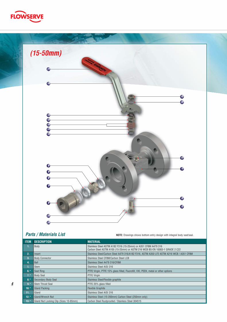
(15-50mm)
21
19
13
12
15
11
10
7
6
4
6
23
24
2
12
22
9
5
17
1
4
Parts / Materials List NOTE: Drawings shows bottom entry design with integral body seat/seal.
ITEM DESCRIPTION MATERIAL1. Body Stainless Steel ASTM A182 F316 (15-25mm) or A351 CF8M A479 316
Carbon Steel ASTM A105 (15-25mm) or ASTM 216 WCB BS-EN 10083-1 GRADE 2 C22
2. Insert Stainless Steel/Carbon Steel A479 316/A182 F316, ASTM A350 LF2 ASTM A216 WCB / A351 CF8M
3. Body Connector Stainless Steel CF8M/Carbon Steel LCB
4. Ball Stainless Steel A479 316/CF8M
5. Stem Stainless Steel AISI 316
6.* Seat Ring PTFE Virgin, PTFE 15% glass filled, Fluorofill, VXI, PEEK, metal or other options
7.* Body Seal PTFE Virgin
8.* Secondary Body Seal Stainless Steel/Flexible graphite
9.* Stem Thrust Seal PTFE 25% glass filled
10.* Gland Packing Flexible Graphite
11. Gland Stainless Steel AISI 316
12.* Gland/Wrench Nut Stainless Steel (15-200mm) Carbon Steel (250mm only)
13.* Gland Nut Locking Clip (Sizes 15-65mm) Carbon Steel Rustproofed / Stainless Steel 304515

(65-250mm)
19
7
8
6
4
6
3
25
12
11
14
23
24
10
16
20
18
9
5
26
1
5
Parts / Materials List NOTE: Drawings shows bottom entry design with integral body seat/seal.
ITEM DESCRIPTION MATERIAL14. Stem Location Washer Stainless Steel
15.* Disc Spring Stainless Steel
16.** Stop Indicator Stainless Steel/Carbon Steel Rustproofed
17. Stop Pin Stainless Steel/Carbon Steel
18.** Wrench Head Malleable Iron
19.** Wrench Stainless Steel (15-50mm Stainless Steel valves) Carbon Steel (all other valves)
20.** Wrench Fixing Bolt Stainless Steel
21.* Wrench Sleeve Vinyl Plastisol
22. Spring Washer Stainless Steel
23. Anti-static Plunger (Note 5 back page) Stainless Steel
24. Anti-static Spring (Note 5 back page) Stainless Steel
25. Body Connector Screw Stainless Steel
26. Identification Plate Stainless Steel* Items marked thus denote component supplied in repair kit. ** Wrench assembly not fitted on size 250mm.

53/54 (15-50mm)
6
Valve Dimensions (mm) - Series 53 (15-250mm)
Valve Port A C D E G H M N Q R S T U X WeightSize (mm) Dia. Max. (kg)
15 11.1 115.0 20.65 11.1 46.0 38.1 90.0 5.54 3/8 U.N.F. - 31.8 152.0 M6 9.2 15.0 2.0
20 14.3 120.0 23.01 11.1 49.3 40.5 92.5 5.54 3/8 U.N.F. - 31.8 152.0 M6 9.2 20.0 3.0
25 20.6 125.0 30.95 15.9 57.2 55.7 113.5 7.54 7/16 U.N.F. - 41.3 165.0 M8 9.7 25.0 3.6
40 31.8 140.0 42.1 19.1 62.3 73.1 117.5 8.71 9/16 U.N.F. - 44.5 190.5 M8 9.7 40.0 6.9
50 38.1 150.0 46.8 19.1 67.8 77.8 122.2 8.71 9/16 U.N.F. - 44.5 190.5 M8 9.7 50.0 9.8
65 50.8 170.0 74.2 17.1 68.0 116.0 143.0 14.0 M20 32.0 70.0 254.0 M8 14.0 63.5 12.6
80 63.5 180.0 98.4 16.7 77.8 145.3 185.3 15.87 23.0 44.5 85.7 350.0 M10 11.1 80.0 18.5
100 82.6 190.0 113.9 16.7 84.1 161.1 201.1 15.87 23.0 44.5 85.7 558.0 M10 11.1 100.0 24.8
150 111.1 350.0 157.2 26.2 120.6 226.2 283.5 23.8 35.3 76.2 101.6 850.0 M12 14.3 150.0 59.0
200 144.5 400.0 184.9 26.2 136.5 254.0 311.3 23.8 35.3 76.2 101.6 850.0 M12 15.9 200.0 86.5
250 203.2 450.0 260.4 30.9 228.6 343.0 475.0 30.3 2-6UN 31.8 209.6 - M16 28.6 255.6 -

53 (65-250mm) & 54 (65-100mm)
7
Valve Dimensions (mm) - Series 54 (15-100mm)
Valve Port A C D E G H M N Q R S T U X WeightSize (mm) Dia. Max. (kg)
15 11.1 130.0 20.65 11.1 46.0 38.1 89.0 5.54 3/8 U.N.F. - 31.8 152.0 M6 9.2 15.0 2.2
20 14.3 150.0 23.01 11.1 49.3 40.5 91.3 5.54 3/8 U.N.F. - 31.8 152.0 M6 9.2 20.0 3.3
25 20.6 160.0 30.95 15.9 57.2 55.6 111.1 7.54 7/16 U.N.F. - 41.3 165.0 M8 9.7 25.0 4.5
32 25.4 180.0 35.72 15.9 60.4 60.4 115.9 7.54 7/16 U.N.F. - 41.3 165.0 M8 9.7 32.0 6.6
40 31.8 200.0 42.1 19.1 62.3 73.1 117.5 8.71 9/16 U.N.F. - 44.5 190.5 M8 9.7 40.0 7.3
50 38.1 230.0 46.8 19.1 67.8 77.8 122.2 8.71 9/16 U.N.F. - 44.5 190.5 M8 9.7 50.0 10.3
65 50.8 290.0 74.2 17.1 68.0 116.0 143.0 14.0 M20 32.0 70.0 254.0 M8 14.0 63.5 15.1
80 63.5 310.0 98.4 16.7 77.8 145.3 185.3 15.87 23.0 44.5 85.7 350.0 M10 11.1 80.0 21.7
100 82.6 350.0 113.9 16.7 84.1 161.1 201.1 15.87 23.0 44.5 85.7 558.0 M10 11.1 100.0 30.3
Due to continuous development of our product range, we reserve the right to alter the dimensions and information contained in this leaflet as required

Flowserve Flow Control A Division of Flowserve GB LtdWorcester ControlsBurrell Road, Haywards HeathWest Sussex RH16 1TLUnited KingdomTelephone: +44 (0)1444 314400Telefax: +44 (0)1444 314401Email: [email protected]
FCD WCEBR0005-01 Printed in Germany. (Replaces PB02 Rev 10/03)
Due to continuous development of our product range, we reserve the right to alter the dimensions andinformation contained in this leaflet as required. Information given in this leaflet is made in good faith andbased upon specific testing but does not, however, constitute a guarantee.
1. Stainless steel valves sizes 15-50mm have stainless steel wrenchesas standard. Other sizes are carbon steel.
3. When wrench not fitted, flats on stem when parallel to pipeline axis,denote ball open position.
4. Installation, Operating and Maintenance instructions are availableon request.
5. For valve sizes 15-50mm only one anti-static spring and plunger is fitted.
Flow Coefficients
45
40
35
30
25
20
15
10
5
580
435
290
145
PN
40 STA
INLE
SS STEEL
PN16 STAINLESS STEEL
45
40
35
30
25
20
15
10
5
580
435
290
145
PN
40 STA
INLE
SS STEEL
PN16 STAINLESS STEEL
PN40 CARBON STEEL
VIR
GIN
PTFE
15%
GL
AS
S F
ILL
ED
VIR
GIN
PT
FE
PN16 CARBON STEEL
VIRGIN/RE-INFORCED PTFE
PN40 CARBON STEEL
80 - 1
50m
m
25 - 5
0m
m
PN16 CARBON STEEL
FLUOROFILL
Standards of Compliance
Pressure Temperature Ratings
Design Specification Generally in accordance with BS 5159(Face to Face as shown below)
Flanges DIN 2543 PN16 DIN 2544 PN25DIN 2545 PN40
Face to Face Length DIN 3202Series 53 15-100mm Col F4Series 53 150-250mm Col F5Series 54 15-100mm Col F1
Pressure Test Specification BS 6755 Pt.1
Firesafe Specification BS 6755 ISO 10497/API 6FABS 5146
Third Party Approvals TA Luft
Notes
How to order Worcester Valves and other Worcester products
Please order Worcester Valves and other products by description, notby part number. We need a precise description of the valve you require.We will then translate this information into our own coding for orderprocessing and production. Please state the despatch address anddesired date of delivery.
Valve Size Limiting Stem Input Torquemm in Nm Lbf in15 ½ 13.2 11720 ¾ 13.2 11725 1 24.4 21640 1½ 48.6 43050 2 48.6 43065 2½ 192 170080 3 385 3400100 4 385 3400150 6 1570 13900200 8 1570 13900250 10 2640 23400
Limiting Stem Input Torque
Valve Size Flow Coefficientsmm in Cv Kv15 ½ 6 720 ¾ 8.7 1025 1 26 3040 1½ 77 8950 2 112.5 13065 2½ 230 26780 3 303 350100 4 623 720150 6 882 1020200 8 1557 1800250 10 2560 2970
Cv - Flow in US GPM Pressure - psi
Kv - Flow in M³/hr Pressure - bar