reduced vertical separation minimum (rvsm)€¦ · · 2017-04-01edition: 1.0 03-02-99 page ii...
TRANSCRIPT

EUROPEAN ORGANISATION FOR THE SAFETY OFAIR NAVIGATION
EUROCONTROL
EUROPEAN AIR TRAFFIC CONTROL HARMONISATIONAND INTEGRATION PROGRAMME
ATC Manual for a
Reduced Vertical SeparationMinimum (RVSM)
in Europe
ASM.ET1.ST13.5000
Edition : 1.0Edition Date : 03-02-99Status : ReleasedClass : EATCHIP

Edition: 1.003-02-99
Page ii
DOCUMENT IDENTIFICATION SHEET
DOCUMENT DESCRIPTION
Document Title
ATC Manual for a Reduced Vertical Separation Minimum(RVSM) in Europe
EWP DELIVERABLE REFERENCE NUMBER: ASM.ET1.ST13.5000
PROGRAMME REFERENCE INDEX EDITION : Approved ANT/18
EDITIONDATE :
03-02-99
Abstract
This manual represents an operational reference document intended for the use of ATS personnelinvolved in the planning, implementation and application of a Reduced Vertical Separation Minimum(RVSM) in Europe.
KeywordsRVSMReduced Vertical Separation MinimumECAC
CONTACT PERSON : E. Sermijn TEL : 3473 DIVISION : DED.4
DOCUMENT STATUS AND TYPE
STATUS CATEGORY CLASSIFICATION
Working Draft ! Executive Task ! General Public "Draft ! Specialist Task ! EATCHIP !Proposed Issue ! Lower Layer Task " Restricted !Released Issue "
ELECTRONIC BACKUP
INTERNAL REFERENCE NAME : N:\Matthieh\RVSM\RVSMMANUAL\MANANT1
HOST SYSTEM MEDIA SOFTWARE(S)Microsoft Windows Type : Hard disk
Media Identification :

ATC Manual for RVSM in Europe
Edition: 1.003-02-99
Page iii
DOCUMENT APPROVAL
The following table identifies all management authorities who have successively approvedthe present issue of this document.
AUTHORITY NAME AND SIGNATURE DATE
Chairman,
ATM ProceduresDevelopment
Sub-Group (APDSG) E. SERMIJN
Chairman,
Airspace andNavigation Team (ANT)
A. HENDRIKS
Programme Manager,
EUROCONTROLRVSM Programme
J. SULTANA
Chairman,
RVSM ProgrammeManagement Board
(PMB) A. HENDRIKS
Senior Director,
EATMP
W. PHILIPP

ATC Manual for RVSM in Europe
Edition: 1.003-02-99
Page iv
DOCUMENT CHANGE RECORD
The following table records the complete history of the successive editions of the presentdocument.
EDITION DATE REASON FOR CHANGESECTIONS
PAGESAFFECTED
Ed. 0.A 06-03-98 Working Draft Document - APDSG/16 ALL
Ed. 0.B 01-05-98 Working Draft Document - APDSG/DraftingGroup
ALL
Ed. 0.C 01-06-98 Working Draft Document - APDSG/17 ALL
Ed. 0.D 15-09-98 Working Draft Document - circulated to APDSGMembers
ALL
Ed. 0.E 15-10-98 Working Draft Document - circulated to ANTMembers
ALL
Ed.Proposed
15-01-99 Submitted to ANT/18 for approval ALL
Ed. 1.0ApprovedANT/18
03-02-99 Approved by ANT/18
----Intentionally Left Blank----

ATC Manual for RVSM in Europe
Edition: 1.003-02-99
Page v
AMENDMENT SUMMARY
Note: This document was developed by EUROCONTROL, DED.4 and will be amended as required.
AmendmentNR/Year
Publicationdate
Dateinserted
Effectivedate
Inserted by
---Intentionally Left Blank---

ATC Manual for RVSM in Europe
Edition: 1.003-02-99
Page vi
CHECKLIST OF PAGES
(Released Edition)
Page Dated Page Dated Page Dated Page Dated
iv 03-02-99 5-3 03-02-99 7-2 03-02-99 D-2 03-02-99
v 03-02-99 5-4 03-02-99 7-3 03-02-99 D-3 03-02-99
vi 03-02-99 5-5 03-02-99 7-4 03-02-99 E-1 03-02-99
vii 03-02-99 5-6 03-02-99 7-5 03-02-99 E-2 03-02-99
vii 03-02-99 5-7 03-02-99 7-6 03-02-99 E-3 03-02-99
viii 03-02-99 5-8 03-02-99 7-7 03-02-99 E-4 03-02-99
ix 03-02-99 5-9 03-02-99 8-1 03-02-99 E-5 03-02-99
x 03-02-99 5-10 03-02-99 8-2 03-02-99 F-1 03-02-99
xi 03-02-99 5-11 03-02-99 8-3 03-02-99 F-2 03-02-99
xii 03-02-99 5-12 03-02-99 8-4 03-02-99 F-3 03-02-99
xiii 03-02-99 5-13 03-02-99 8-5 03-02-99 F-4 03-02-99
xiv 03-02-99 5-14 03-02-99 8-6 03-02-99 F-5 03-02-99
1-1 03-02-99 5-15 03-02-99 8-7 03-02-99 F-6 03-02-99
1-2 03-02-99 5-16 03-02-99 8-8 03-02-99 F-7 03-02-99
1-3 03-02-99 5-17 03-02-99 8-9 03-02-99 G-1 03-02-99
1-4 03-02-99 5-18 03-02-99 8-10 03-02-99 G-2 03-02-99
1-5 03-02-99 5-19 03-02-99 8-11 03-02-99 G-3 03-02-99
1-6 03-02-99 5-20 03-02-99 8-12 03-02-99 G-4 03-02-99
1-7 03-02-99 5-21 03-02-99 9-1 03-02-99 G-5 03-02-99
1-8 03-02-99 5-22 03-02-99 9-2 03-02-99 G-6 03-02-99
2-1 03-02-99 5-23 03-02-99 9-3 03-02-99 G-7 03-02-99
2-2 03-02-99 5-24 03-02-99 9-4 03-02-99 G-8 03-02-99
2-3 03-02-99 5-25 03-02-99 10-1 03-02-99 G-9 03-02-99
3-1 03-02-99 5-26 03-02-99 10-2 03-02-99 G-10 03-02-99
3-2 03-02-99 5-27 03-02-99 A-1 03-02-99 G-11 03-02-99
4-1 03-02-99 5-28 03-02-99 B-1 03-02-99 G-12 03-02-99
5-1 03-02-99 6-1 03-02-99 C-1 03-02-99 G13 03-02-99
5-2 03-02-99 7-1 03-02-99 D-1 03-02-99 H-1 03-02-99

ATC Manual for RVSM in Europe
Edition: 1.003-02-99Page vii
TABLE OF CONTENTS
DOCUMENT IDENTIFICATION SHEET................................................................................ ii
DOCUMENT APPROVAL .................................................................................................... iii
DOCUMENT CHANGE RECORD ........................................................................................ iv
AMENDMENT SUMMARY.....................................................................................................v
CHECKLIST OF PAGES......................................................................................................VI
TABLE OF CONTENTS.......................................................................................................vii
ABBREVIATIONS .......................................................................................................... ......x
DEFINITIONS........................................................................................................................xi
EXECUTIVE SUMMARY.....................................................................................................xiii
1. INTRODUCTION 1-1
1.1 Background 1-1
1.2 The Need for RVSM 1-2
1.3 History 1-4
1.4 The EATCHIP RVSM Implementation Programme 1-6
1.5 Supporting Documentation 1-7
2. DESCRIPTION OF THE EUROPEAN RVSM AIRSPACE 2-1
2.1 The European RVSM airspace 2-1
2.2 The European RVSM Transition airspace 2-1
2.3 Table of Cruising Levels applicable to the European RVSM Airspace 2-3
3. PROVISION OF SERVICE TO NON-RVSM APPROVED STATE AIRCRAFT 3-1
4. FLIGHT OPERATIONS WITHIN THE EUROPEAN RVSM AIRSPACE 4-1
5. PROCEDURES 5-1
5.1 General Procedures 5-1
ATC Manual for RVSM in Europe
Edition: 1.003-02-99Page viii
5.2 Procedures for State Aircraft operating as Operational Air Traffic (OAT), Crossing ATSRoutes, within the RVSM Airspace 5-4
5.3 Flight Planning 5-5
5.4 Inter-Centre Co-ordination 5-9
5.5 Contingency Procedures 5-11
5.6 Transition Procedures 5-19
5.7 Phraseology 5-24
6. VERTICAL SPACING FROM TSAs, PROHIBITED, RESTRICTED AND DANGERAREAS 6-1
7. COMMUNICATIONS FAILURE IN FLIGHT 7-1
7.1 TRANSITION AIRSPACE 7-1
7.2 OTHER RVSM AIRSPACE 7-7
8. ATS SYSTEMS SUPPORT 8-1
8.1 General 8-1
8.2 Flight Data Processing Systems 8-1
8.3 Radar Display Systems 8-4
8.4 Flight Strips (Paper or Electronic) 8-6
8.5 OLDI 8-8
8.6 ATS Systems Overview 8-9
8.7 STCA/MTCD 8-11
9. ATC CONSIDERATIONS 9-1
9.1 Inter-Centre Letters of Agreement 9-1
9.2 Flight Level Allocation Schemes 9-2
9.3 Sectorisation 9-2
9.4 Optimisation of the ATS Route Structure 9-3
10. ACAS 10-1
ATC Manual for RVSM in Europe
Edition: 1.003-02-99
Page ix
APPENDIX A - RVSM TABLE OF CRUISING LEVELS
APPENDIX B - RVSM/NON-RVSM TRANSITION
APPENDIX C - FEET - METRIC TRANSITION
APPENDIX D - AIRWORTHINESS
APPENDIX E - STATE APPROVAL OF AIRCRAFT FOR RVSM OPERATIONS
APPENDIX F - FLIGHT CREW TRAINING PROGRAMMES AND OPERATINGPRACTICES AND PROCEDURES
APPENDIX G - SYSTEM PERFORMANCE MONITORING
APPENDIX H - LIST OF CONTACTS
----Intentionally Left Blank---
ATC Manual for RVSM in Europe
Edition: 1.003-02-99
Page x
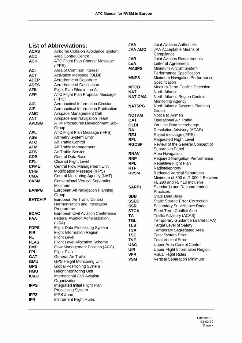
List of Abbreviations:ACAS Airborne Collision Avoidance SystemACC Area Control CentreACH ATC Flight Plan Change Message
(IFPS)ACI Area of Common InterestACT Activation Message (OLDI)ADEP Aerodrome of DepartureADES Aerodrome of DestinationAFIL Flight Plan Filed in the AirAFP ATC Flight Plan Proposal Message
(IFPS)AIC Aeronautical Information CircularAIP Aeronautical Information PublicationAMC Airspace Management CellANT Airspace and Navigation TeamAPDSG ATM Procedures Development Sub-
GroupAPL ATC Flight Plan Message (IFPS)ASE Altimetry System ErrorATC Air Traffic ControlATM Air Traffic ManagementATS Air Traffic ServiceCDB Central Data BaseCFL Cleared Flight LevelCFMU Central Flow Management UnitCHGCMA
Modification Message (IFPS)Central Monitoring Agency (NAT)
CVSM Conventional Vertical SeparationMinimum
EANPG European Air Navigation PlanningGroup
EATCHIP European Air Traffic ControlHarmonisation and IntegrationProgramme
ECAC European Civil Aviation ConferenceFAA Federal Aviation Administration
(USA)FDPS Flight Data Processing SystemFIR Flight Information RegionFL Flight LevelFLAS Flight Level Allocation SchemeFMP Flow Management Position (ACC)FPL Flight PlanGAT General Air TrafficGMU GPS Height Monitoring UnitGPS Global Positioning SystemHMU Height Monitoring UnitICAO International Civil Aviation
OrganizationIFPS Integrated Initial Flight Plan
Processing SystemIFPZ IFPS ZoneIFR Instrument Flight Rules
JAA Joint Aviation AuthoritiesJAA AMC JAA Acceptable Means of
ComplianceJAR Joint Aviation RequirementsLoA Letter of AgreementMASPS Minimum Aircraft System
Performance SpecificationMNPS Minimum Navigation Performance
SpecificationMTCD Medium Term Conflict DetectionNAT North AtlanticNAT CMA North Atlantic Region Central
Monitoring AgencyNATSPG North Atlantic Systems Planning
GroupNOTAM Notice to AirmenOAT Operational Air TrafficOLDI On-Line Data InterchangeRA Resolution Advisory (ACAS)REJ Reject message (IFPS)RFL Requested Flight LevelRGCSP Review of the General Concept of
Separation PanelRNAV Area NavigationRNP Required Navigation PerformanceRPL Repetitive Flight PlanRTF RadiotelephonyRVSM Reduced Vertical Separation
Minimum of 300 m /1 000 ft BetweenFL 290 and FL 410 Inclusive
SARPs Standards and RecommendedPractices
SDB State Data BaseSSEC Static Source Error CorrectionSSR Secondary Surveillance RadarSTCA Short Term Conflict AlertTA Traffic Advisory (ACAS)TGL Temporary Guidance Leaflet (JAA)TLS Target Level of SafetyTSA Temporary Segregated AreaTSE Total System ErrorTVE Total Vertical ErrorUAC Upper Area Control CentreUIR Upper Flight Information RegionVFR Visual Flight RulesVSM Vertical Separation Minimum

ATC Manual for RVSM in Europe________________________________________________________________________________________
Edition: 1.003-02-99
Page xi
DEFINITIONS
Flight Level Allocation Scheme (FLAS):
The scheme whereby specific flight levels may be assigned to specific
route segments within the route network.
General Air Traffic (GAT)
Flights conducted in accordance with the rules and provisions of ICAO.
Operational Air Traffic (OAT)
Flights which do not comply with the provisions stated for GAT and for
which rules and procedures have been specified by appropriate authorities.
RVSM Approval:
The approval that is issued by the appropriate authority of the State in
which the Operator is based or of the State in which the aircraft is
registered. To obtain such RVSM approval, Operators shall satisfy the said
State:
1) that aircraft for which the RVSM Approval is sought have the
vertical navigation performance capability required for RVSM
operations through compliance with the criteria of the RVSM
Minimum Aircraft Systems Performance Specification (MASPS).
2) that they have instituted procedures in respect of continued
airworthiness (maintenance and repair) practices and
programmes.
3) that they have instituted flight crew procedures for operations in
the EUR RVSM airspace.
Note: For the purposes of the application of RVSM, the term: “RVSM APPROVED” shall
be used to indicate that an aircraft has been granted RVSM Approval.

ATC Manual for RVSM in Europe
Edition: 1.003-02-99Page xii
RVSM Entry Point
The first reporting point over which an aircraft passes or is expected to
pass immediately before, upon, or immediately after initial entry into
European RVSM airspace, normally the first reference point for applying a
reduced vertical separation minimum.
RVSM Exit Point
The last reporting point over which an aircraft passes or is expected to pass
immediately before, upon, or immediately after leaving European RVSM
airspace, normally the last reference point for applying a reduced vertical
separation minimum.
State Aircraft
Aircraft used in military, customs and police services shall be deemed to be
State aircraft.
Ref: ICAO, Convention on International Civil Aviation, Article 3 (b.
Strategic Flight Level:
A flight level which is flight-plannable in accordance with the Table of
Cruising Levels of ICAO Annex 2, Appendix 3 and the FLAS, as specified in
the relevant Aeronautical Information Publications (AIPs).
Tactical Flight Level:
A flight level which is not flight-plannable and which is reserved for tactical
use by ATC.

ATC Manual for RVSM in Europe
Edition: 1.003-02-99Page xiii
EXECUTIVE SUMMARY
The application of a reduced vertical separation minimum in the airspace of the European
Civil Aviation Conference (ECAC) Member States and other States participating in the
European RVSM Programme, represents a change of major significance to the
operational environments of those ACCs/UACs involved. Careful planning in advance of
the implementation of RVSM will ensure that benefits in terms of capacity and operating
efficiency are optimised, and that controllers will be able to successfully cope with the
magnitude of the change to their operational environments, thereby ensuring continued
levels of safety.
Text within this manual, highlighted through the use of a shaded box, describe ATC
procedures and system support requirements as dictated by identified operational
requirements and as endorsed by the EATCHIP Airspace and Navigation Team. In
support of these ATC procedures and system support requirements, the manual serves as
a guidance and reference document for those operational and management ATS
personnel involved with the planning for the implementation of RVSM. As well, it will serve
as a reference document for those personnel involved with the continuing ATC operations
of ACCs/UACs in an RVSM environment.
The manual will address those elements of the European ATM system which are impacted
directly by, or have an impact on, RVSM implementation and application.
While the document describes the European RVSM airspace, ATC procedures, ATC
phraseologies and relevant flight crew procedures associated with the application of
RVSM, it does not supersede the relevant ICAO and national documents.
Throughout this document the use of the term: “European RVSM airspace” has been
incorporated to reflect the application of RVSM within the airspace not only of Member
States of ECAC, but also within certain States adjacent to ECAC, which have decided to
participate in the RVSM Programme. Although originally intended for implementation only
within the ECAC Member States as a capacity enhancing element of the European Air
Traffic Control Harmonisation and Integration Programme (EATCHIP), additional States
bordering the ECAC area will as well implement RVSM in their airspace, in order to

ATC Manual for RVSM in Europe
Edition: 1.003-02-99Page xiv
achieve a homogeneous European RVSM airspace and to share in the expected benefits
of RVSM.
----Intentionally Left Blank----

ATC Manual for RVSM in Europe_______________________________________________________________________________________
Edition: 1.003-02-99Page 1-1
1. INTRODUCTION
1.1 Background
The implementation of a reduced vertical separation minimum represents a major capacity
enhancing objective of the European Air Traffic Control Harmonisation and Integration
Programme (EATCHIP) Work Programme. Effectively, the introduction of RVSM will
permit the application of a 1 000 ft vertical separation minimum (VSM) between suitably
equipped aircraft in the level band FL 290-FL 410 inclusive, thereby making available six
additional usable flight levels. The purpose of the implementation of RVSM is to increase
capacity, through the provision of these six additional flight levels, to reduce controller
workload, while maintaining, or improving upon, current levels of safety, and to provide the
airspace user community with an improved operating environment for optimising flight
profiles.
The making available of these additional levels is one of the means which will enable
controllers:
• to efficiently handle both the current and future levels of traffic within their areas of
responsibility,
• to de-conflict strategically traffic over the major crossing points of the European ATS
route network more effectively, and
• to accommodate pilot requests for optimal cruising levels.
As described below, and as a pre-requisite to the introduction of RVSM in the ECAC
airspace, implementation of RVSM requires that levels of safety of operations within the
European RVSM airspace, when compared to current levels of safety, be either
maintained or improved. Work undertaken by EUROCONTROL in the form of real-time
simulations and safety studies have confirmed the feasibility of implementing RVSM, both
technically and operationally, within required levels of safety. Experience gained through
the application of RVSM within the ICAO North Atlantic (NAT) Region has been used in
the development of the relevant associated aspects of the implementation of RVSM in the
European airspace. In this way, consistency in flight operations across the two operational
ATC environments was maintained to the maximum extent possible. Furthermore, the

ATC Manual for RVSM in Europe
Edition: 1.003-02-99Page 1-2
EATCHIP RVSM Programme has been undertaken in close co-ordination with the
European Air Navigation Planning Group (EANPG) of ICAO. The material developed as a
result of the EATCHIP RVSM Programme is in accordance with all relevant ICAO
Standards and Recommended Practices (SARPs) and associated ICAO Guidance
Material on both RVSM and ATS. Thus, the implementation of RVSM in the European
airspace is undertaken with due consideration for consistency with applications of the
concept, both existing and planned, in other regions.
1.2 The Need for RVSM
Over the last five years, improvements brought about by EATCHIP have contributed to
containing the duration, and frequency of occurrence, of ATC delays despite annual
increases of between 3 to 10%. However, current forecasts indicate that air traffic
movements will continue to rise, and will more than double by the year 2015 compared to
1996 figures. The anticipated trends are illustrated at Figure 1.
2000
4000
6000
8000
10000
12000
19
86
19
88
19
90
19
92
19
94
19
96
19
98
20
00
20
02
20
04
20
06
20
08
20
10
20
12
20
14
An
nu
al N
um
ber
of
IFR
Flig
hts
(in
th
ou
san
ds)
Actual
Low
Base
High
Trends
Figure 1. Traffic Statistics and Forecasts
It is accepted that major changes to the ATM systems will be necessary in order to cope
with this continued traffic growth. Of the various measures under consideration, the

ATC Manual for RVSM in Europe
Edition: 1.003-02-99Page 1-3
implementation of RVSM is considered to be the most cost effective means of meeting
this need through the provision of six additional flight levels for use in the highly congested
airspace from FL 290 to FL 410 inclusive. The RVSM Programme will result in the
following benefits:
• Optimum Route Profiles.
The availability of the additional flight levels in the busiest level band, will allow
operators to plan for, and operate at or closer to, the optimum vertical route profile
for the particular aircraft type. This will provide fuel economies in terms of both the
fuel carried, and the fuel burn, for the flight. The economies are estimated at
between 0.5% and 1% of the total fuel burn which has been translated to overall
savings of 155 million ECU over the 20 year period following RVSM
implementation1.
• Increased ATC Capacity
A series of ATC Real Time Simulations carried out at the EUROCONTROL
Experimental Centre (EEC) at Bretigny, France, have provided evidence that
RVSM can reduce controller workload. The simulations demonstrated that the
capacity of those sectors simulated could be increased by approximately 20%
when compared to a conventional vertical separation minimum (CVSM)
environment2. There is also potential for further growth, through a revised airspace
structure including, for example, resectorisation and/or the introduction of
additional sectors.
However, the presence of non-RVSM approved State aircraft, which have been
exempted3 from having to meet the RVSM Minimum Aircraft System Performance
Specification (MASPS) requirements for operations in European RVSM airspace
(see Part 3), and which are required to operate regularly as GAT along the ATS
route network, will decrease the expected capacity gains. Evidence from the
continuing operation of RVSM in the NAT region indicates that a large proportion of
1 PA Consulting Group: Cost Benefit Assessment of RVSM Implementation2 3rd Continental RVSM Real-Time Simulation, S08, (Conclusions)3 certain military tactical aircraft cannot, due to physical limitations, be adapted to meet RVSMMASPS

ATC Manual for RVSM in Europe
Edition: 1.003-02-99Page 1-4
State aircraft operating as GAT are nevertheless RVSM approved. This trend is
expected to continue.
1.3 History
In the late 1950s it was recognised that, as a result of the reduction in accuracy of
pressure-sensing of barometric altimeters with increasing altitude, there was a need
above a certain flight level to increase the prescribed vertical separation minimum (VSM)
of 1 000 ft. In 1960, an increased VSM of 2 000 ft was established for use between aircraft
operating above FL 290 except where, on the basis of regional air navigation agreement,
a lower flight level was prescribed for the increase. The selection of FL 290 was not so
much an empirically-based decision but rather a function of the operational ceiling of
aircraft at that time. In 1966, this change-over level was established at FL 290 on a global
basis. At the same time, it was considered that the application of a reduced VSM above
FL 290, on a regional basis and in carefully prescribed circumstances, was a distinct
possibility in the not too distant future. Accordingly, ICAO provisions stated that such a
reduced VSM could be applied under specified conditions within designated portions of
airspace on the basis of regional air navigation agreements.
In the late 1970s, faced with rising fuel costs and growing demands for a more efficient
utilisation of the available airspace, ICAO initiated a comprehensive programme of studies
to examine the feasibility of reducing the 2 000 ft VSM applied above FL 290, to the same
1 000 ft VSM which is applied below FL 290. Throughout the 1980s, various studies were
conducted, under the auspices of ICAO and in Europe, Canada, Japan, and the United
States. The underlying approach of the programmes was to:
• determine the height keeping accuracy of the altimetry systems of the then
current aircraft population.
• establish the causes of observed height keeping errors.
• determine the required safety levels for the implementation and use of a
Reduced Vertical Separation Minimum (RVSM) of 1 000 ft in the level band
FL 290 - FL 410 inclusive.
• define a MASPS, for aircraft altimetry and associated height keeping
equipment, which would improve height keeping accuracy to a standard
compatible with the agreed safety requirements for RVSM.
• determine whether the global implementation and use of RVSM was :

ATC Manual for RVSM in Europe
Edition: 1.003-02-99Page 1-5
1. technically feasible, subject to the over-riding need to satisfy the agreed
safety standards, and
2. cost beneficial.
The results of these exhaustive studies demonstrated that the reduction of vertical
separation was safe, cost beneficial and feasible, - without the imposition of unduly
demanding technical requirements.
The studies also showed that the types of aircraft and the essentially unidirectional flow of
traffic in the North Atlantic Minimum Navigation Performance Specifications (MNPS)
airspace, made the NAT Region an ideal candidate for the first implementation of RVSM.
Planning for RVSM in the NAT Region commenced in 1990. The first stage of the
Operational Evaluation phase, using the 1 000 ft RVSM, began on the 27th March 1997 in
the level band FL 330 and FL 370 inclusive. The application of RVSM was extended in a
second stage to encompass FL 310, FL 320, FL 380 and FL 390 in October 1998.
From the outset it was clear that the complex nature of the European ATS route structure,
the wide variety of aircraft types, high traffic density and the high percentage of climbing
and descending aircraft, would be a more complex ATM environment than the North
Atlantic Region for the implementation of RVSM. Thus, safety considerations were given a
high priority in the initial ECAC RVSM feasibility studies which were conducted under the
auspices of the EUROCONTROL Airspace and Navigation Team (ANT). These studies
indicated that, subject to aircraft meeting the altimetry MASPS, RVSM could be introduced
into the European Region without compromising required safety levels, and also that it
would provide a positive benefit to cost ratio over a wide range of assumptions regarding
future developments within the European aviation environment.

ATC Manual for RVSM in Europe
Edition: 1.003-02-99Page 1-6
1.4 The EATCHIP RVSM Implementation Programme
The Programme consists of a series of co-ordinated activities, performed within the
EUROCONTROL Agency, ICAO, Joint Aviation Authorities (JAA), Participating States and
User Organisations.
The programme has followed the general strategy set out in the ICAO Doc. 9574 (First
Edition) - “Manual on Implementation of a 300 m (1 000 ft) Vertical Separation Minimum
Between FL 290 and FL 410 Inclusive” which proposed a multi-step approach within four
distinct phases :
Phase 1: Initial Planning
• Step 1: Assessment of Operational System Safety
• Step 2: Assessment of Costs and Benefits from RVSM
• Step 3: Elaboration of programme plans and production of technicalspecifications.
This phase was completed in June 1997. The EATCHIP Project Board reviewed the
progress made on the RVSM Programme and recommended that work should continue so
that full implementation can be achieved on the target date of November 2001. This
programme was endorsed by the ICAO European Air Navigation Planning Group
(EANPG) in December 1997.
Phase 2: Advanced Planning and Preparation
In this phase the emphasis of the work programme moved from the theory and initial
design of the total system to the practical application and introduction of the system
requirements. The objectives of this phase were:
1. to prepare the aircraft for RVSM operations
2. to prepare a monitoring environment to allow confirmation of the technical
performance of aircraft
3. to commence the preparation of the ATS environment for RVSM operation.

ATC Manual for RVSM in Europe
Edition: 1.003-02-99Page 1-7
Note: Points 1 and 2 will allow Phase 3 to start, point 3 is pre-requisite to Phase 4.
Phase 3 : Verification of Aircraft Performance
The purpose of the Verification Phase, is to confirm, in a 2 000 ft vertical separation
environment:
• the effectiveness of the RVSM approval process;
• the effectiveness of the MASPS, by measuring the height keeping performance
accuracy of the maximum possible number of aircraft which have obtained
RVSM airworthiness approval;
• that the safety levels of the proposed RVSM system will remain at, or be better
than, those established by the Target Level of Safety (TLS).
This phase will continue until all aspects of the work programme necessary to the
successful completion of the verification process have been completed. This is expected
to take approximately one year.
Phase 4 : Introduction of RVSM
The introduction of RVSM does not mark the end to the Programme. This phase of the
programme will be used to confirm that:
• all elements of the total system are operating satisfactorily,
• the level of “vertical risk” in the system is below that tolerated by the TLS.
This phase will support the resolution of any operational issues which might be revealed
following the implementation of 1 000 ft VSM.
Phase 4 will continue until it is possible to confirm that the long term safety of 1 000 VSM
can be assured without further monitoring.
1.5 Supporting Documentation

ATC Manual for RVSM in Europe
Edition: 1.003-02-99Page 1-8
The following reference documents will be amended to incorporate the changes
necessitated by the introduction of RVSM in European airspace:
• ICAO Doc. 7030 - European (EUR) Regional Supplementary Procedures
• ICAO Doc. 9574 - Manual on Implementation of a 300 m (1 000 ft) Vertical
Separation Minimum between FL 290 and FL 410 Inclusive.
The following documents are in the course of preparation and will provide the detailed
procedures and requirements necessary for the implementation of RVSM in the European
RVSM airspace:
• ICAO Guidance Material on the Implementation and Application of a 300 m
(1 000ft) Vertical Separation Minimum in the European RVSM Airspace.
• JAA Temporary Guidance Leaflet on Approval of Aircraft and Operators for
Flight in RVSM Airspace - TGL No.6.
• National AICs and/or. AIPs
----Intentionally Left Blank---

ATC Manual for RVSM in Europe_______________________________________________________________________________________
Edition: 1.003-02-99Page 2-1
2. DESCRIPTION OF THE EUROPEAN RVSM AIRSPACE
2.1 The European RVSM airspace
2.1.1 RVSM shall be applicable in that volume of airspace between FL 290 and FL 410
inclusive in the following FIRs/UIRs:
Amsterdam, Ankara, Athinai, Barcelona, Beograd, Berlin, Bodo, Bratislava,
Bremen, Brindisi, Brussels, Bucuresti, Budapest, Canaries (ICAO AFI Region),
Dusseldorf, France, Frankfurt, Hannover, Istanbul, Kaliningrad, Kobenhavn,
Kishinev, Lisboa, Ljubljana, London, Madrid, Malmo, Malta, Milano, Munchen,
Nicosia, Oslo, Praha, Rhein, Riga. Roma, Rovaniemi, Sarajevo, Scottish,
Shannon, Skopje, Sofia, Stavanger, Stockholm, Sundsvall, Switzerland, Tallinn,
Tampere, Tirana, Trondheim, Varna, Vilnius, Warszawa, Wien, Zagreb.
RVSM shall as well be applicable, between FL 290 and FL 410 inclusive, in all, or
part of, the following FIRs/UIRs:
Casablanca, Simferopol, Odesa, L’viv
2.2 The European RVSM Transition airspace
Transition tasks, associated with the application of RVSM within the European
RVSM airspace, shall be carried out in the following peripheral FIRs/UIRs:
Ankara, Athinai, Barcelona, Bodo, Canaries (ICAO AFI Region), Casablanca,
France, L'viv, Madrid, Malta, Nicosia, Odesa, Riga, Roma, Rovaniemi, Simferopol,
Tallinn, Tampere, Vilnius, Warszawa

ATC Manual for RVSM in Europe_______________________________________________________________________________________
Edition: 1.003-02-99Page 2-2
Figure 2: Depiction of European and NAT RVSM areas with list of 39 States participating inthe European RVSM Programme.
Albania LuxembourgAustria MaltaBelgium MoldovaBosnia and Herzegovina MonacoBulgaria MoroccoCroatia The NetherlandsCyprus NorwayCzech Republic PolandDenmark PortugalEstonia RomaniaFederal Republic of YugoslaviaSlovak RepublicFinland SloveniaFrance SpainGermany SwedenGreece SwitzerlandHungary The Former Yugoslav Republic of MacedoniaIreland TurkeyItaly UkraineLatvia United KingdomLithuania

ATC Manual for RVSM in Europe_______________________________________________________________________________________
Edition: 1.003-02-99Page 2-3
2.3 Table of Cruising Levels applicable to the European RVSM Airspace
Flight levels within the European RVSM airspace will be organised on the basis of
their intended use in regards to direction of flight, in accordance with ICAO Annex
2, Appendix 3, para. a), Table of Cruising Levels. Graphically, such an organisation
is described as follows:
FL430*
FL410 FL400 FL390 FL380 FL370 FL360 FL350 FL340 FL330 FL320 FL310 FL300 FL290 FL280*
* non-RVSM level
Tracks 000° - 179° (or 090° - 269° in the FIRs/UIRs of Italy,France, Portugal and Spain)
Tracks 180° - 359° (or 270° - 089° in the FIRs/UIRs of Italy,
France, Portugal and Spain)
It is to be noted from the above that the application of RVSM, has the effect of
reversing the assignment of FLs 310, 350 and 390 with respect to their use in
regards to direction of flight, as compared to airspace where RVSM is not applied.
----Intentionally Left Blank---


ATC Manual for RVSM in Europe_______________________________________________________________________________________
Edition: 1.003-02-99Page 3-1
3. PROVISION OF SERVICE TO NON-RVSM APPROVED STATE AIRCRAFT
3.1 In consideration of the physical inability (due to limitations in aircraft design) of
adapting the large majority of military tactical aircraft to the defined RVSM
MASPS, discussions took place within the relevant EATCHIP Working Groups
which included the means by which the requirements of military flight operations,
within RVSM airspace, could be met. As an outcome of the discussions, State
aircraft were exempted from having to meet the RVSM MASPS. However,
EUROCONTROL has urged States to adapt their State aircraft, operating as GAT
along ATS routes, to the RVSM MASPS, to the maximum extent possible.
Nonetheless, certain types of State aircraft cannot feasibly be adapted to the point
where they would be RVSM MASPS compliant. These aircraft will nevertheless be
permitted to operate as either OAT or GAT in the RVSM airspace.
When operating in the European RVSM airspace, such non-RVSM approved State
aircraft operating as GAT, will be provided with a minimum vertical separation of
2 000 ft from all other IFR aircraft. Although the number of non-RVSM approved
State aircraft operating as GAT within the RVSM airspace is expected to be very
small, the impact which the handling of such flights will have on controller workload
is not to be underestimated.
3.2 The requirement for ATC to accommodate non-RVSM approved State aircraft
within the RVSM airspace imposes operational considerations of a very high order.
Several real time simulations carried out by EUROCONTROL in support of the
RVSM Work Programme have confirmed that significant increases in controller
workload result from the requirement of having to selectively apply two distinct
vertical separation minima (VSM) within the same volume of airspace, namely:
1 000 ft: between any two aircraft operating as GAT where both aircraft are
RVSM approved, or
2 000 ft: between any two aircraft operating as GAT where either:
• one of the aircraft involved is non-RVSM approved, or
• both of the aircraft involved are non-RVSM approved

ATC Manual for RVSM in Europe
Edition: 1.003-02-99Page 3-2
3.3 Of prime operational importance, therefore, is the requirement that controllers be
continually aware of the RVSM approval status of all aircraft operating within or in
close proximity to RVSM airspace situated within the ACC’s/UAC’s areas of
responsibility. To support this requirement, operational system requirements and
ATC procedures have been developed.
3.4 Specific ATC and flight planning procedures in this regard are described in Part 5
while the automated systems adaptations necessary to support the requirements
mentioned above, are detailed in Part 8.
note: see para. 5.6 in regards to the provision of service to non-RVSM approved civil aircraft within the RVSMtransition airspace
----Intentionally Left Blank---

ATC Manual for RVSM in Europe_______________________________________________________________________________________
Edition: 1.003-02-99Page 4-1
4. FLIGHT OPERATIONS WITHIN THE EUROPEAN RVSM AIRSPACE
4.1 Except for State aircraft and as provided for in para. 5.6 (Transition Procedures)
only RVSM approved aircraft shall be permitted to operate within the RVSM
airspace.
4.2 Except for State aircraft operating as OAT, only flight operations conducted under
IFR shall be permitted in the RVSM airspace.
Reference ICAO Annex 2, Chapter 4, Para. 4.5:
“Authorization for VFR flights to operate above FL 290 shall not be granted in
areas where a vertical separation minimum of 300 m (1 000 ft) is applied above FL
290.”
Note: The provisions of ICAO Annex 2 described above, also preclude VFR flight operations
above FL 410, in areas where RVSM is implemented between FL 290 and FL 410 inclusive.
4.3 The organisation of flight levels within the RVSM airspace, as described in para.
2.3, does not preclude the establishment of uni-directional ATS Routes where
deemed necessary.
Furthermore, it is noteworthy, that the assigning of a particular level, by ATC to a
particular aircraft within the RVSM airspace, is not a function of that aircraft’s
RVSM approval status. All levels are therefore equally assignable to either RVSM
approved or non-RVSM approved aircraft, provided that the applicable VSM is
applied.

ATC Manual for RVSM in Europe_______________________________________________________________________________________
Edition: 1.003-02-99Page 5-1
5. PROCEDURES
Note: Text within shaded areas represent approved ATC procedures.
The ATC procedures related to RVSM include the following:
• General Procedures
• Procedures for non-RVSM approved State aircraft operating as General Air
Traffic (GAT) within the RVSM airspace
• Procedures for State aircraft operating as Operational Air Traffic (OAT),
Crossing ATS Routes, within the RVSM Airspace
• Flight planning procedures
• Inter-centre co-ordination procedures
• Contingency procedures
• Transition procedures
• Phraseology
5.1 General Procedures
5.1.1 ATC shall only clear RVSM approved aircraft into the RVSM airspace, except for
State aircraft and except as provided for in para. 5.6 (transition procedures).
Except for State aircraft, operations within the RVSM airspace are restricted to
RVSM approved aircraft. Flight planning provisions in relation to RVSM will make
possible the display of the RVSM related flight plan information to enable
controllers to be systematically aware of any particular aircraft’s RVSM approval
status.
5.1.2 ATC shall provide a minimum of 1 000 ft vertical separation between RVSM
approved aircraft operating within the RVSM airspace.
Within the RVSM airspace, a reduced vertical separation minimum of 1 000 ft may
only be applied between two aircraft where both aircraft are RVSM approved.
ATC Manual for RVSM in Europe
Edition: 1.003-02-99Page 5-2
Within the RVSM transition airspace (see para. 2.2), and supplemental to the
conditions specified in para. 5.1.1 above, non-RVSM approved civil aircraft
proceeding from non-RVSM airspace to RVSM airspace will be accommodated, for
the purpose of clearing such aircraft to levels appropriate to adjacent FIRs/UIRs
situated within the lateral limits of the RVSM airspace. Such aircraft shall be
provided with a VSM of 2 000 ft from all other aircraft while operating within RVSM
airspace where transition tasks are carried out.
5.1.3 ATC shall provide a minimum of 2 000 ft vertical separation between any non-
RVSM approved State aircraft and any other aircraft operating within the RVSM
airspace.
See 5.1.4 below.
5.1.4 In airspace where transition tasks are carried out (see para. 2.2), ATC shall
provide a minimum of 2 000 ft vertical separation between any non-RVSM
approved aircraft (Civil or State) and any other aircraft.
For all cases where an aircraft operating within the RVSM airspace is non-RVSM
approved, it shall be provided with a minimum vertical separation of 2 000 ft.
5.1.5 Except as provided for in para. 5.6 (Transition Procedures), ATC shall withhold
clearance into the RVSM airspace to all formation flights of civil aircraft.
ICAO Annex 2, Ch. 3, provides that aircraft participating in formation flights are
permitted to operate within 100 ft above or below the flight leader. Consequently,
the operation of the formation as a whole, could compound the allowable variation
for total vertical error (Appendix E refers) for the flight leader within RVSM
airspace, and as such the formation would not comply with the required RVSM
MASPS. Formation flights shall therefore be considered as being non-RVSM
approved. Nonetheless, such formation flights of civil aircraft will be permitted to
operate within RVSM airspace where transition tasks are carried out, as described
in para. 5.6.

ATC Manual for RVSM in Europe
Edition: 1.003-02-99Page 5-3
Definition (ICAO): “Total Vertical Error” (TVE): Vertical geometric difference
between the actual pressure altitude flown by an aircraft and
its assigned pressure altitude (flight level).
5.1.6 ATC shall provide a minimum of 2 000 ft vertical separation between all formation
flights of State aircraft and any other aircraft operating within the RVSM airspace.
For the reasons discussed in Para. 5.1.5 above, formation flights of State aircraft
shall be considered as being non-RVSM approved, regardless of the RVSM
approval status of the individual aircraft concerned. Inasmuch as State aircraft
have been exempted from having to meet the requirements of the RVSM MASPS
for the RVSM airspace, such formation flights of State aircraft will be
accommodated within the RVSM airspace and shall be provided with a
minimum vertical separation of 2 000 ft from any other aircraft.
5.1.7 ATC shall assign flight levels to non-RVSM approved aircraft, other than State
aircraft, in accordance with the table below:
ADES within lateral limits
of RVSM airspace
ADES outside lateral limits
of RVSM airspace
ADEP within lateral
limits of RVSM
airspace
Assign level below
RVSM airspace
Assign level below RVSM
airspace
ADEP outside lateral
limits of RVSM
airspace
Assign level below
RVSM airspace
Assign level below or
above RVSM airspace
Note: Controllers should review the description of the RVSM airspace in Para. 2 in regards to the
lateral limits of the RVSM airspace.
Non-RVSM approved aircraft, departing from and landing at an aerodrome situated
outside the lateral limits of the RVSM airspace, could operate at flight levels above
the RVSM airspace, since ATC would, as a consequence, not be required to
subsequently descend such aircraft through the RVSM airspace.

ATC Manual for RVSM in Europe
Edition: 1.003-02-99Page 5-4
5.2 Procedures for State Aircraft operating as Operational Air Traffic(OAT), Crossing ATS Routes, within the RVSM Airspace
5.2.1 The majority of State aircraft operating as OAT will be non-RVSM MASPS
compliant. Therefore, as a basic principle, and unless otherwise notified, State
aircraft operating as OAT shall be considered as being non-RVSM approved.
As previously mentioned, it is not possible, for physical reasons resulting from
limitations in design, to adapt the large majority of tactical military aircraft to
meeting the RVSM MASPS defined for the RVSM airspace.
5.2.2 The minimum vertical separation required between (a) State aircraft operating as
OAT, crossing ATS routes, and (an) aircraft operating as GAT, where both are
operating within the RVSM airspace, shall be 2 000 ft.
5.2.2.1 However, in an airspace environment where both the civil and military ATC units
are fully aware as to the RVSM approval status of all traffic involved, a reduced
vertical separation of 1 000 ft may be applied between an RVSM approved State
aircraft operating as OAT, and RVSM approved GAT.
Provision is made for the application of a reduced vertical separation minimum of
1 000 ft between OAT and GAT aircraft where either advanced civil-military co-
ordination systems, which systematically display the RVSM approval status of all
aircraft involved to the respective controllers, are in use or where verbal co-
ordination, including RVSM approval information of the individual aircraft, is
accomplished.
---Intentionally Left Blank---

ATC Manual for RVSM in Europe
Edition: 1.003-02-99Page 5-5
5.3 Flight Planning
5.3.1 The flight plan submitted for a flight intending to operate across the lateral limits of
the RVSM airspace shall include:
• the entry point at the lateral limits of the RVSM airspace and the specific
requested flight level (RFL) for that portion of the route commencing
immediately after the entry point;
• the exit point at the lateral limits of the RVSM airspace and the specific
requested flight level (RFL) for that portion of the route commencing
immediately after the exit point.
Note: See defintions, RVSM Entry/Exit Points
For all ATS routes crossing the lateral limits of the RVSM airspace, compulsory
reporting points will be established on/near the boundaries with the non-RVSM
airspace. Communication failure procedures require the description of these points
for the purpose of defining the beginning of the time parameter specified in ICAO
communication failure procedures. Specifically, operations extending across the
lateral limits of the RVSM airspace require that precise information regarding the
aircraft’s requested flight level (RFL) for that portion of flight before, within and
after, as applicable, the lateral limits of the RVSM airspace be available to support
the requirements of ICAO communication failure procedures. Due to the
incompatibility of flight levels in RVSM airspace with those flight levels in non-
RVSM airspace, with regard to their intended use in relation to direction of flight
(para. 2.3 refers), ATC will require precise information as to the RFL for those
portions of flight immediately after entry and/or exit to/from RVSM airspace.
Information regarding the specific RFL of an aircraft for that portion of flight
before/after the compulsory reporting point, will ensure the eventual operation of
the aircraft at a level appropriate to the operating environment of the accepting
ACC/UAC, in the event of a communication failure in flight.
See para. 7, Communications Failure in Flight.

ATC Manual for RVSM in Europe
Edition: 1.003-02-99Page 5-6
5.3.2 All operators of RVSM approved aircraft, shall insert the letter “W” in Item 10 of the
ICAO Flight Plan, regardless of the requested flight level.
The letter “W” has been adopted to indicate RVSM approval status. It is consistent
with flight planning provisions for the ICAO North Atlantic Region (NAT). Operators
are required to indicate their RVSM approval status regardless of RFL, since ATC
must additionally be aware of an aircraft’s RVSM approval status when operating
in close vertical proximity to the RVSM airspace. ATC shall have an unambiguos
indication of an aircraft’s RVSM approval status when intending to clear an aircraft
into the RVSM airspace. In absence of such an indication, the controller shall
solicit such information.
Note: See para. 5.7.1.1 and 5.7.1.2 for relevant RTF Phraseology.
See Definitions: RVSM Approval.
5.3.3 All operators of non-RVSM approved State aircraft with a requested flight level
(RFL) of FL 290 or above, shall insert the phrase “STS/NONRVSM” in Item 18 of
the ICAO Flight Plan.
“STS/NONRVSM” will indicate the request for “special handling” by ATS, namely,
a requirement for ATC to provide a minimum vertical separation of 2 000 ft
between such flights and other aircraft operating within the RVSM airspace. Non-
RVSM approved State aircraft, even though filing an RFL above FL410, a level at
which no special handling would be required in terms of providing the minimum
vertical separation, will nevertheless be required to indicate this request, since
special handling by ATC will be required for that portion of the flight consisting of
the vertical transit through the RVSM airspace.
5.3.4 In addition to operators of military aircraft, operators of customs or police aircraft
shall insert the letter “M” in Item 8 of the ICAO Flight Plan if non-RVSM approved
and intending to operate within the RVSM airspace.
Aircraft used in military, customs, or police service are deemed to be State aircraft.
ICAO flight planning provisions currently only permit the identification of those
flights in military service (ICAO Flight Plan Item 8) through the use of the letter
ATC Manual for RVSM in Europe
Edition: 1.003-02-99Page 5-7
“M”. The application of this letter has been expanded to permit the identification of
flights in customs or police services as State aircraft to ATC. The Initial Integrated
Flight Planning System (IFPS) shall disseminate this information to the flight data
processing systems (FDPS) concerned for the purpose of providing ATC with the
required clear indication that such non-RVSM approved flights, are in fact “State
aircraft” and as such are permitted to operate within the RVSM airspace.
5.3.5 All operators filing Repetitive Flight Plans (RPLs) shall include in Item Q of the RPL
equipment information in regards to the RVSM approval status in the format
“EQPT/W”, for flights operated by RVSM approved aircraft and “EQPT/ ”, for
flights operated by non-RVSM approved aircraft, with operational service ceilings
corresponding to FL 280 or above, regardless of the requested flight level.
ICAO flight planning provisions in regards to the filing of RPLs do not provide for
the ability to indicate ICAO Flight Plan Item 10 information (e.g.: RVSM approved,
Letter “W”) as an element of an RPL. Nevertheless, ATC must be in possession of
this information for each individual flight on day of operation. For this reason, ICAO
European regional flight planning provisions will require the relevant ICAO Flight
Plan Item 10 information, in regards to a flight’s RVSM approval status, to be filed
as an element of RPLs in the above-mentioned format. For each individual flight on
day of operation, IFPS shall generate and distribute flight plans, from stored RPL
information, containing the relevant RVSM approval status.
(Ref.: CFMU Handbook, “IFPS Users Manual”, Ed. 4.0, Para. 9.5)
5.3.6 If a change of aircraft operated in accordance with a repetitive flight plan results in
a modification of the RVSM approval status as stated in Item Q, a modification
message (CHG) shall be submitted by the operator.
5.3.7 Operators of non-RVSM approved State aircraft, filing RPLs including an RFL of
FL 290 or above, shall include “STS/NONRVSM” in Item Q.
see para. 5.3.3 above.
5.3.8 Regardless of the RVSM approval status of the individual aircraft concerned, the
letter “W” shall never be inserted in Item 10 of flight plans related to formation
flights of State aircraft.

ATC Manual for RVSM in Europe
Edition: 1.003-02-99Page 5-8
See para. 5.1.6 above.
5.3.9 Operators of formation flights of State aircraft intending to operate as GAT in
RVSM airspace shall include “STS/NONRVSM” in Item 18 of the ICAO Flight
Plan.
Formation flights of State aircraft will be accommodated within the RVSM airspace
and will be considered as being non-RVSM approved, regardless of the RVSM
approval status of the individual aircraft involved. As such, they shall request
special handling by ATC and be provided with a minimum vertical separation of
2 000 ft from all other aircraft operating within the RVSM airspace.
----Intentionally Left Blank----

ATC Manual for RVSM in Europe
Edition: 1.003-02-99Page 5-9
RVSM approved?
State Aircraft?
RFL at or above
FL290?
Insert STS/NONRVSM
in Item 18
Insert M
in Item 8
Avoid RVSM Airspace
Insert W
in Item 10
Y
N
N
NY
Y
No extra indication
Formation Flight?
Y
N
Figure 3 : Overview of RVSM Flight Planning Requirements for Operators
5.4 Inter-Centre Co-ordination
5.4.1 Computer-assisted co-ordination of estimate messages:
The On-Line Data Interchange (OLDI) System should support the co-ordination of
requests for special handling (i.e.: STS) as filed in Item 18 of the ICAO Flight Plan.
Since the Activation (ACT) Message replaces the verbal estimate message, and
notwithstanding the fact that the information should be contained within the local
FDPS, a clear indication as to an aircraft’s non-RVSM approval status and its
request for special handling, should be included as an integral part of the
automated estimate message:
• as confirmation of the data filed in the flight plan, as it is very safety critical

ATC Manual for RVSM in Europe
Edition: 1.003-02-99
Page 5-10
• to cover the case where degradation of capability in the performance of flight
planning systems has occurred for a particular flight, and
• to cover the case where, for whatever reason, the accepting unit has not
received the flight plan.
5.4.1.1 In the case of automated messages not containing the information provided in Item
18 of the flight plan relating to RVSM operations, the sending air traffic control unit
shall inform the receiving air traffic control unit of that information by
supplementing the ACT message verbally.
The term “NEGATIVE RVSM” or “NEGATIVE RVSM STATE AIRCRAFT”, as
applicable, shall be used to verbally supplement such automated estimate
messages.
5.4.2 Verbal Co-ordination of Estimate Messages
When a verbal co-ordination process is being used, the sending air traffic control
unit shall include the information filed in Item 18 of the ICAO flight plan, relevant to
RVSM operations, at the end of the verbal estimate message.
The term “NEGATIVE RVSM” or “NEGATIVE RVSM STATE AIRCRAFT”, as
applicable, shall be included at the end of the verbal estimate message.
5.4.3 For the case of a single aircraft experiencing an in flight contingency, the
associated co-ordination messages shall be supplemented verbally by a
description of the cause of the contingency.
The associated co-ordination messages shall incorporate either the term:
• UNABLE RVSM DUE EQUIPMENT, or
• UNABLE RVSM DUE TURBULENCE, as appropriate.

ATC Manual for RVSM in Europe
Edition: 1.003-02-99
Page 5-11
5.5 Contingency Procedures
Note: Para. 5.7 below contains the phraseologies associated with contingency
events.
In respect to RVSM operations, a contingency event refers to a set of unforeseen
circumstances, which directly impact on the ability of a single aircraft, or a group of
aircraft, to operate in accordance with the height keeping requirements of the
RVSM airspace. ATC, once advised of the occurrence of such an event, shall
provide the concerned aircraft with a Vertical Separation Minimum (VSM) of
2 000 ft. from all other aircraft operating in the RVSM airspace while the concerned
aircraft operates in RVSM airspace.
Such contingency events relate to either:
• degradation of aircraft equipment associated with height keeping or
• occurrence of weather phenomenon resulting in turbulent atmospheric
conditions which directly affect the ability of aircraft to maintain their CFLs,
and are further discussed below.
Para. 5.7.1 describes precise pilot RTF Phraseology which shall be used to convey
to ATC the precise nature of the contingency. Pilots shall inform ATC, on a timely
basis, of circumstances which prevent them from maintaining CFL within
tolerances required for RVSM airspace.
Controllers must react to these contingency events, but their actions cannot be
specified as they will be dynamically affected by the real-time situation.
5.5.1 Procedures applicable to individual aircraft, equipment related:
The RVSM MASPS required for operation within the RVSM airspace require, as a
minimum, that aircraft be equipped with, at the least:
• two fully serviceable independent primary altitude measurement systems
• one automatic altitude-control system

ATC Manual for RVSM in Europe
Edition: 1.003-02-99
Page 5-12
• one altitude-alerting device
• one Mode C SSR Transponder, where so prescribed by the appropriate ATS
Authority for the airspace of intended operation.
Failure in flight, of any component of the above minimum equipment fit required for
RVSM operations, shall render the aircraft non-RVSM approved. Pilots
experiencing such in-flight failures shall report this contingency event as soon as
practicable to ATC. Additionally, pilots shall inform ATC of other equipment failures
which affect the aircraft’s ability to maintain the CFL.
5.5.1.1 Where an aircraft’s Mode C displayed level differs from the CFL by 300 ft or more,
the controller shall inform the pilot accordingly and the pilot shall be requested to
both check the pressure setting and confirm the aircraft’s level.
If after confirmation of the aircraft’s level, the Mode C readout continues to differ
from the CFL by 300 ft or more, ATC will follow the existing ICAO procedures
prescribed for the failure of Mode C in flight.
The allowable tolerance for Mode C readout of 300 ft remains applicable within
RVSM airspace. Such 300 ft parameter relates solely to SSR transponder
operation. It does not relate to the height keeping accuracy required by the RVSM
MASPS.
5.5.1.2 When informed by the pilot that the aircraft’s equipment has degraded to below
RVSM MASPS compliance levels while operating within the RVSM airspace, the
controller shall either provide for a minimum vertical separation of 2 000 ft or an
appropriate horizontal separation. Controllers shall normally clear the aircraft below
FL 290 (or, alternatively, above FL 410 if the destination aerodrome is outside the
lateral limits of the RVSM airspace) before the next inter-centre transfer of control
point, unless otherwise co-ordinated.
Such aircraft shall be considered as being non-RVSM approved and, as a
consequence, require a minimum 2 000 ft vertical separation. ATC shall
immediately upon receipt of information indicating an equipment related
contingency event which causes the aircraft to become non-RVSM approved, take

ATC Manual for RVSM in Europe
Edition: 1.003-02-99
Page 5-13
action to ensure the application of either a minimum 2 000 ft vertical separation or
an appropriate horizontal separation from other aircraft operating as GAT in the
RVSM airspace. ATC shall subsequently, to the extent the radar display system
makes possible, manually manipulate the display of the concerned aircraft’s
associated radar label and/or radar position symbol, for the purpose of clearly
distinguishing such radar label and/or radar position symbols in accordance with
established local radar display features applicable to non-RVSM approved aircraft.
Note: See also para. 8.4, Radar Display Systems
Although actual circumstances will dictate the relative priority which ATC can
assign to the task of clearing the aircraft in question out of the RVSM airspace, the
continued operation of aircraft, rendered non-RVSM approved as a result of an
equipment related contingency event, within the RVSM airspace is highly
discouraged. The ability to accurately distinguish such aircraft in accordance with
locally established procedures regarding automated systems, in contradiction to
the RVSM approval information originally filed by the operator in the flight plan,
may render the practice unsafe.
ATC shall normally clear RVSM approved State aircraft experiencing a similar
equipment related contingency resulting in non-MASPS compliance, to a level
outside the RVSM airspace as soon as practicable.
Although non-RVSM approved State aircraft, are under normal circumstances
permitted to operate within the RVSM airspace, the ability to accurately co-ordinate
the non-RVSM approval status, contrary to information which had originally been
disseminated by IFPS and/or OLDI, would be compromised and render inadvisable
the continued operation of such aircraft in the RVSM airspace.
It is imperative that ATC accurately co-ordinate the specifics related to the
contingency event through the use of the appropriate associated co-ordination
messages:
“UNABLE RVSM DUE EQUIPMENT” or “UNABLE RVSM DUE TURBULENCE”,
(as applicable)

ATC Manual for RVSM in Europe
Edition: 1.003-02-99
Page 5-14
Pilots will inform ATC as soon as practicable of any eventual restoration of the
proper functioning of those equipment related elements required for operation in
RVSM airspace. ATC will as a result, be in a position to consider clearing the
aircraft into the RVSM airspace applying a 1 000 ft vertical separation minimum. As
well, ATC would manually remove the application of the locally adapted
distinguishing feature, associated with such aircraft, from the radar display.
5.5.2 Procedures applicable to individual aircraft, weather related:
5.5.2.1 For the case of an individual aircraft reporting severe turbulence preventing the
aircraft from maintaining its CFL, the controller shall establish either an appropriate
horizontal separation, or an increased minimum vertical separation.
The specific actions to be taken by ATC will be dictated by the actual weather-
related circumstances and the traffic situation existing at the time. ATC is expected
to use best judgement to safeguard separation between aircraft in these
circumstances and to accommodate, to the extent possible, pilot requests for level
changes.
ATC shall co-ordinate the circumstances of the weather related contingency by
verbally supplementing the estimate message with: “UNABLE RVSM DUE
TURBULENCE”.
ATC shall manually apply the distinguishing feature of the radar label to such
aircraft until such time as the pilot reports to be in a position to resume operations
in accordance with RVSM.
Aircraft experiencing severe turbulence need not be cleared out of the RVSM
airspace. Such flights continue to be RVSM approved and as such, comply with
the basic requirements for operation within the RVSM airspace.

ATC Manual for RVSM in Europe
Edition: 1.003-02-99
Page 5-15
5.5.2.2 If informed of the existence of severe turbulence, the controller shall solicit other
relevant turbulence reports to determine, in co-ordination with the Supervisor,
whether RVSM operations should be suspended entirely or within a specific level
band and/or area.
----Intentionally Left Blank---

ATC Manual for RVSM in Europe
Edition: 1.003-02-99
Page 5-16
5.5.3 Procedures for multiple aircraft, weather related, non-predicted:
5.5.3.1 For the case of immediate requirements where a controller has received no
advance warning of impending meteorological conditions that could create severe
turbulence, the controller shall provide for an increased minimum vertical
separation or an appropriate horizontal separation, and the following action(s),
although not exhaustive, should be considered:
• since each real time situation will demand very specific, distinct actions, the
controller should use his/her best judgement to ensure the safety of the
aircraft under his/her responsibility.
• the controller should pass traffic information to the extent possible
• the controller will co-ordinate with the Supervisor for the purpose of
determining whether RVSM operations will be suspended entirely or within
a specific level band and/or area.
• if a reversion to a 2 000 ft vertical separation minimum is deemed
necessary, co-ordination with adjacent ACCs/UACs shall be accomplished
to ensure an orderly progression to the transfer of traffic using a 2 000 ft
vertical separation as the minimum
• Supervisors may co-ordinate, to the extent deemed necessary, a request
for the deactivation of any airspace restrictions and/or reservations required
to provide additional radar vectoring airspace necessary to facilitate the
transition to a 2 000 ft vertical separation minimum
• the Supervisor should co-ordinate with the parent Flight Management
Position (FMP) to adjust the applicable sector capacities

ATC Manual for RVSM in Europe
Edition: 1.003-02-99
Page 5-17
5.5.4 Procedures for multiple aircraft, weather related, predicted
For the case of meteorological conditions causing severe turbulence, predicted by
Meteorological Services, the procedures required will of consequence be of a
strategic nature. A meteorological forecast, predicting severe turbulence, received
by an ACC, will demand of the ACC/UAC Supervisor a decision as to whether
RVSM operations are to be interrupted, for what period of time, and for what
specific level(s) and/or area. Should an increased vertical separation be
necessary, the Supervisor will co-ordinate with the adjacent ACCs/UACs
concerned as to the flight levels appropriate for the transfer of traffic, unless a
contingency flight level allocation scheme (FLAS) has been determined in the
Letter of Agreement. The Supervisor should co-ordinate with the parent Flight
Management Position (FMP) to establish the applicable sector capacities. The
issuance of a NOTAM should be considered as circumstances require.
Consideration should be given to the development of contingency FLASs to
supplement existing FLASs between ACCs/UACs. Such contingency FLASs
should be described in Letters of Agreement for the purpose of being applied, after
the necessary inter-centre co-ordination, during times of weather related
contingency events, be they predicted or non-predicted. The development of such
contingency FLASs would greatly facilitate the transition to a 2 000 ft vertical
separation minimum within the RVSM airspace
The application of a contingency FLAS will be facilitated through the designation of
levels within the contingency FLAS that are consistent with their designations in
the corresponding normal RVSM FLAS, with regard to their intended use for
direction of flight.

ATC Manual for RVSM in Europe
Edition: 1.003-02-99
Page 5-18
Centre A
Centre B
Centre C
Bi-directional
Uni-directional
FL300
FL320
FL330
FL290
FL350
FL360
FL370
FL380
FL390
FL410
FL310
FL340
FL300
FL320
FL330
FL290
FL350
FL360
FL370
FL380
FL390
FL410
FL310
FL340
FL400 FL400
Figure 4 - Example description of a Contingency FLAS
In regards to facilitating the co-ordination and establishment of new capacity
figures for the ACC/UAC, during contingency events requiring the reversion to a
2,000 ft VSM within the RVSM airspace, ACCs/UACs should consider
predetermining such capacity figures for the purpose of permitting rapid co-
ordination with the local FMP.
The importance of obtaining timely accurate forecasts of severe turbulence should
be stressed within agreements with the appropriate meteorological services office
responsible for the dissemination of such information for the area concerned.
ContingencyFLAS,VSM=2 000 ft
Normal RVSMFLAS,VSM=1 000 ft
The application of the contingency FLAS, when required, is facilitated by virtue of the fact that the use ofthe levels within the “Contingency FLAS” is consistent with their use in the “Normal RVSM FLAS”.
Example: When informed by Centre A that the Contingency FLAS is to be applied, Centre C wouldbe required to discontinue the use of FL 360 for traffic to be transferred to Centre A, however Centre Bwould not be required to alter the use of FL 320. In this way, the operational impact upon Centre B ismitigated and Centre B’s ability to establish aircraft at levels appropriate for Centre A is greatly facilitated.
ATC Manual for RVSM in Europe
Edition: 1.003-02-99
Page 5-19
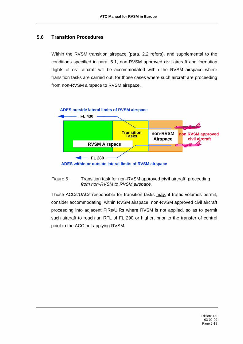
5.6 Transition Procedures
Within the RVSM transition airspace (para. 2.2 refers), and supplemental to the
conditions specified in para. 5.1, non-RVSM approved civil aircraft and formation
flights of civil aircraft will be accommodated within the RVSM airspace where
transition tasks are carried out, for those cases where such aircraft are proceeding
from non-RVSM airspace to RVSM airspace.
RVSM Airspace
TransitionTasks
ADES outside lateral limits of RVSM airspace
ADES within or outside lateral limits of RVSM airspace
non RVSM approved civil aircraft
FL 280
non-RVSMAirspace
FL 430
Figure 5 : Transition task for non-RVSM approved civil aircraft, proceedingfrom non-RVSM to RVSM airspace.
Those ACCs/UACs responsible for transition tasks may, if traffic volumes permit,
consider accommodating, within RVSM airspace, non-RVSM approved civil aircraft
proceeding into adjacent FIRs/UIRs where RVSM is not applied, so as to permit
such aircraft to reach an RFL of FL 290 or higher, prior to the transfer of control
point to the ACC not applying RVSM.

ATC Manual for RVSM in Europe
Edition: 1.003-02-99
Page 5-20
RVSM Airspace
TransitionTasks
non-RVSM approved civil aircraft
CFL: FL 270RFL: FL 330
non-RVSMAirspace
CFL: FL 330
Figure 6 : Transition task for non-RVSM approved civil aircraft, proceedingfrom RVSM to non-RVSM airspace.
5.6.1 For aircraft to be transferred from RVSM airspace to non-RVSM airspace, the last
ACC/UAC providing air traffic control service to such aircraft within the RVSM
airspace shall establish a minimum of 2 000 ft vertical separation before the
aircraft passes the transfer of control point to the adjacent non-RVSM ACC
established at a flight level
• in accordance with the ICAO Table of Cruising Levels as published in ICAO
Annex 2, Appendix 3, table b), and/or
• in accordance with the FLAS, if applicable, and/or
• as specified in the inter-centre Letter of Agreement.
ICAO Annex 2, Appendix 3, table b), describes the assignment of flight levels
according to direction of flight for a non-RVSM environment.
----Intentionally Left Blank---

ATC Manual for RVSM in Europe
Edition: 1.003-02-99
Page 5-21
RVSM Airspace west of non-RVSM Airspace:
RVSM Airspace TransitionTasks
non-RVSM Airspace
FL 350
FL 310FL 330
FL 370
RVSM approvedcivil aircraft and
State aircraft
RVSM Airspace east of non-RVSM Airspace:
RVSM approvedcivil aircraft and
State aircraft
FL 360
FL 320
FL 350
FL 310
TransitionTasksnon-RVSM
Airspace
RVSM Airspace
Figure 7 : Example Transition Task, from RVSM to non-RVSM airspace
5.6.2 For aircraft transferred from non-RVSM airspace to RVSM airspace, the first ACC
providing air traffic control service to such aircraft within the RVSM airspace shall
ensure that RVSM approved aircraft and non-RVSM approved State aircraft are
cleared so as to be established at a flight level
• in accordance with the ICAO Table of Cruising Levels as published in ICAO
Annex 2, Appendix 3, table a), and/or
• in accordance with the FLAS, if applicable and/or
• as specified in the inter-centre Letter of Agreement,
before the aircraft passes the transfer of control point to the adjacent ACC.
ICAO Annex 2, Appendix 3, table a), describes the assignment of flight levels
according to direction of flight for an RVSM environment.

ATC Manual for RVSM in Europe
Edition: 1.003-02-99
Page 5-22
RVSM Airspace west of non-RVSM Airspace:
RVSM Airspace TransitionTasks
FL 360
FL 300 FL 310
FL 350
non-RVSM Airspace
RVSM approvedcivil aircraft and
State aircraft
RVSM Airspace east of non-RVSM Airspace:
TransitionTasks
FL 330
FL 370
FL 330
FL 370
RVSM approvedcivil aircraft and
State aircraft
non-RVSM Airspace
RVSM Airspace
Figure 8 : Transition Tasks, from non-RVSM to RVSM airspace
----Intentionally Left Blank---

ATC Manual for RVSM in Europe
Edition: 1.003-02-99
Page 5-23
5.6.3 For aircraft landing at an aerodrome within the lateral limits of the RVSM airspace,
the first ACC providing air traffic control service within RVSM airspace to aircraft
transferred from non-RVSM airspace to RVSM airspace shall ensure that non-
RVSM approved aircraft, except State aircraft, are cleared so as to be established
at a flight level below FL 290
• in accordance with the FLAS, if applicable and/or
• as specified in the inter-centre Letter of Agreement,
before the aircraft passes the transfer of control point to the adjacent ACC within
the lateral limits of the RVSM airspace.
RVSM Airspace TransitionTasks
FL 360
FL 280
FL 310
FL 350
non-RVSM Airspace
RVSM approvedcivil aircraft and
State aircraft
non-RVSM approvedcivil aircraft
Figure 9: Transition Task, from non-RVSM airspace to RVSM airspace
5.6.4 For aircraft landing at an aerodrome outside, and transiting the lateral limits of, the
RVSM airspace, the first ACC providing air traffic control service to aircraft within
the RVSM airspace, transferred from non-RVSM airspace to RVSM airspace, shall
ensure that non-RVSM approved aircraft, except State aircraft, are cleared so as to
be established at a flight level below FL 290 or above FL 410 before the aircraft
passes the transfer of control point to the adjacent ACC
• in accordance with the FLAS, if applicable, and/or
• as specified in the inter-centre Letter of Agreement.
RVSM AirspaceTransition
Tasks
ADES outside lateral limits of RVSM airspace
non RVSM approved civil aircraft
FL 300
non-RVSMAirspace
FL 430
RVSM approvedcivil aircraft and
State aircraft
FL 390
FL 310
Figure 10: Transition Task, from non-RVSM to RVSM airspace

ATC Manual for RVSM in Europe
Edition: 1.003-02-99
Page 5-24
5.7 Phraseology
5.7.1 Controller-pilot RTF Phraseology:
(* indicates a pilot transmission)
Para Message Phraseology5.7.1.1 To ascertain the RVSM
approval status of a flight: (callsign) CONFIRM RVSM APPROVED
5.7.1.2 Pilot indication of non-RVSMapproval status:
To be stated:I. in the initial call on any
frequency within theRVSM airspace(controllers shallprovide a readbackwith this samephrase), and
II. in all requests for flightlevel changespertaining to flightlevels within the RVSMairspace
III. in all readbacks toflight level clearancespertaining to flightlevels within the RVSMairspace
As well, pilots of aircraft, otherthan State aircraft, shall
respond to level clearancesinvolving the vertical transit
through either FL 290 orFL 410 with this phrase.
See examples below.
Pilot indication of RVSMapproval status:
NEGATIVE RVSM *
AFFIRM RVSM*
5.7.1.3 State aircraft, non-RVSMapproved, shall indicate their
status as being that of a Stateaircraft, in conjunction with a
negative response to the RTF

ATC Manual for RVSM in Europe
Edition: 1.003-02-99
Page 5-25
indicated in Para. 5.7.1.1, withthe phrase: NEGATIVE RVSM STATE AIRCRAFT*
5.7.1.4 Denial of clearance into theRVSM airspace: (callsign) UNABLE CLEARANCE INTO
RVSM AIRSPACE, MAINTAIN [orDESCEND TO, or CLIMB TO] FLIGHTLEVEL (number)
5.7.1.5 For the case of an individualaircraft reporting severe
turbulence or other severeweather related phenomenon,the pilot phraseology shall be: UNABLE RVSM DUE TURBULENCE*
5.7.1.6 The phraseology required of apilot to communicate thosecircumstances which would
cause an aircraft’s equipmentto degrade to below altimetry
MASPS compliance levelsshall be:
The phrase is to be used toconvey both the initial
indication of the non-altimetryMASPS compliance and,
henceforth, on initial contacton all frequencies within the
lateral limits of the RVSMairspace until such time as the
problem ceases to exist.
UNABLE RVSM DUE EQUIPMENT*
5.7.1.7 The pilot shall communicatehis/her ability to resume
operation within the RVSMairspace after an equipment
related contingency, or his/herability to resume RVSM
operations after a weatherrelated contingency with the
phrase: READY TO RESUME RVSM*
5.7.1.8 Controllers wishing to solicitthis information shall use the
phrase: REPORT ABLE TO RESUME RVSM

ATC Manual for RVSM in Europe
Edition: 1.003-02-99
Page 5-26
Example 1: A non-RVSM approved State aircraft operating as GAT, maintaining
FL 260, subsequently requests a climb to FL 320.
Pilot RTF: (callsign) REQUEST FL 320, NEGATIVE RVSM
Controller RTF:(callsign) CLIMB TO FL 320
Pilot RTF: (callsign) CLIMB TO FL 320, NEGATIVE RVSM
Example 2: A non-RVSM approved State aircraft operating as GAT, maintaining
FL 260, subsequently requests a climb to FL 430.
Pilot RTF: (callsign) REQUEST FL430, NEGATIVE RVSM
Controller RTF:(callsign) CLIMB TO FL 430
Pilot RTF: (callsign) CLIMB TO FL 430, NEGATIVE RVSM
Example 3: A non-RVSM approved State aircraft operating as GAT, maintaining
FL 360, subsequently requests a climb to FL 380.
Pilot RTF: (callsign) REQUEST FL 380, NEGATIVE RVSM
Controller RTF:(callsign) CLIMB TO FL 380
Pilot RTF: (callsign) CLIMB TO FL 380, NEGATIVE RVSM
Example 4: A non-RVSM approved civil aircraft maintaining FL 280
subsequently requests a climb to FL 320.
Pilot RTF: (callsign) REQUEST FL 320, NEGATIVE RVSM
Controller RTF:(callsign) UNABLE CLEARANCE INTO RVSM
AIRSPACE, MAINTAIN FL 280

ATC Manual for RVSM in Europe
Edition: 1.003-02-99
Page 5-27
5.7.2 Co-ordination between ATS units:
Para Message Phraseology5.7.2.1 To verbally supplement an
automated estimate messageexchange which does not
automatically transfer Item 18information: NEGATIVE RVSM or
NEGATIVE RVSM STATE AIRCRAFT[as applicable]
5.7.2.2 To verbally supplementestimate messages of non-
RVSM approved aircraft: NEGATIVE RVSM orNEGATIVE RVSM STATE AIRCRAFT[as applicable]
5.7.2.3 To communicate the cause ofa single aircraft contingency: UNABLE RVSM DUE TURBULENCE [or
EQUIPMENT, as applicable]


ATC Manual for RVSM in Europe_______________________________________________________________________________________
Edition: 1.003-02-99Page 6-1
6. VERTICAL SPACING FROM TSAs, PROHIBITED, RESTRICTED ANDDANGER AREAS
All activities occurring within airspace restrictions and/or reservations are to be
considered as being non-RVSM approved.
Consequently, the minimum vertical spacing required between the vertical limits of
the activities contained within such airspace restrictions and/or reservations and
non-participating aircraft operating within the RVSM airspace is:
• 2 000 ft, above the upper limit of such activities, for upper limits of FL
290 or above, and
• 2 000 ft, below the lower limit of such activities, for lower limits of FL 300
or above.
Therefore, the application of RVSM will continue to require that the same minimum
vertical spacing be applied between activities occurring within airspace restrictions
and/or reservations and non-participating aircraft, as were being applied prior to
RVSM implementation.
States will, as stipulated in the ASM Handbook, promulgate the first usable flight
levels above/below airspace restrictions and/or reservations, in the definition of the
associated ATS routes. Depending on the methodology used to delineate and
promulgate such airspace restrictions and/or reservations, the first usable flight
levels will be situated either 1 000 ft or 2 000 ft above/below the published vertical
limits of the airspace restrictions and/or reservations. Nevertheless, operation by
non-participating aircraft at such first usable flight levels, defined as a function of
one of the two delineation methodologies, will guarantee the application of the
required minimum 2 000 ft vertical spacing from the activities occurring within
airspace restrictions and/or reservations.
However, in an airspace environment where the responsible ATS units are fully
aware as to the RVSM approval status of all traffic involved, a reduced vertical
separation of 1 000 ft may be applied between RVSM approved aircraft.


ATC Manual for RVSM in Europe_______________________________________________________________________________________
Edition: 1.003-02-99Page 7-1
7. COMMUNICATIONS FAILURE IN FLIGHT
7.1 TRANSITION AIRSPACE
The existing ICAO Communication Failure Procedures do not lend themselves
satisfactorily to application in that European RVSM airspace where transition tasks
are carried out. Specifically, the length of time to elapse (twenty minutes) before an
aircraft will adjust level and speed in accordance with the filed flight plan, could be
excessive for those instances where the aircraft is flight planned to cross the lateral
limits of the RVSM airspace. Such aircraft could operate over large distances at a
flight level inappropriate to an adjacent RVSM or non-RVSM operating
environment.
Consequently, the application by aircraft of the ICAO provisions regarding aircraft
experiencing communications failure in flight could cause operational problems
both to those ACCs/UACs controlling RVSM airspace and to those ACCs/UACs
controlling adjacent non-RVSM airspace.
7.1.2 A requirement that aircraft report over a compulsory reporting point in the vicinity of
the boundary between RVSM and non-RVSM FIRs/UIRs is recognised, since such
reports would provide the means of establishing for both the pilot and the controller
that a communication failure exists, and thus to determine the time from which the
period of 20 minutes starts.
7.1.3 It is recalled that the filed flight plan will contain the specific entry point for RVSM
airspace and the requested flight level for operating within RVSM airspace, as well
as the specific exit point from RVSM airspace and the requested flight level for the
subsequent non-RVSM airspace (reference para. 5.3.1).
7.1.4 Two scenarios are representative of the operational issues associated with
communications failure in the transition airspace, namely where RVSM airspace is
west of non-RVSM airspace and where RVSM airspace is east of non-RVSM
airspace4.
4 or north and south where predominate traffic flows prescribe the use of flight levels, with regard todirection of flight, on this basis.

ATC Manual for RVSM in Europe
Edition: 1.003-02-99Page 7-2
RVSM Airspace Transition Airspace non-RVSM Airspace
FL 410
FL 400
FL 390
FL 380
FL 370
FL 360
FL 350
FL 340
FL 330
FL 320
FL 310
FL 300
FL 290
FL 410
FL 390
FL 370
FL 350
FL 330
FL 310
FL 290
OppositeDirection
OppositeDirection
OppositeDirection
Figure 11: Scenario where RVSM airspace is west5 of non-RVSM airspace.
RVSM Airspace
FL 410
FL 400
FL 390
FL 380
FL 370
FL 360
FL 350
FL 340
FL 330
FL 320
FL 310
FL 300
FL 290
non-RVSM Airspace
FL 410
FL 390
FL 370
FL 350
FL 330
FL 310
FL 290
Transition Airspace
Figure 12: Scenario where RVSM airspace is east6 of non-RVSM airspace 5 or north, where predominate traffic flows prescribe the use of flight levels, with regard to direction of flight, ona north/south basis.
6 or south, where predominate traffic flows prescribe the use of flight levels, with regard to direction of flight,on a north/south basis.

ATC Manual for RVSM in Europe
Edition: 1.003-02-99Page 7-3
7.1.4 As is apparent from the two scenarios described above, there is a significant
difference regarding the impact of a communication failure, depending on whether
the RVSM airspace is located to the west or to the east of the non-RVSM airspace,
namely:
7.1.4.1 West
• In Figure 11, the RVSM airspace is located to the west of the non-RVSM
airspace. FLs 290, 330, 370 and 410 are “same-direction” flight levels
(eastbound) in both RVSM and non-RVSM airspace.
• Aircraft at FLs 310, 350 and 390 are however “opposite-direction” flight
levels. Therefore, specific revised communication failure procedures need
to be developed for this case.
7.1.4.2 East
• In Figure 12, the RVSM airspace is located to the east of the non-RVSM
airspace. FLs 290, 330, 370 and 410 are “same-direction” flight levels
(eastbound) in both RVSM and non-RVSM airspace.
• There are no flight levels which would have aircraft as opposite traffic if
operating on the same ATS route, thus, no specific revised communication
failure procedures need to be developed for this case.
7.1.5 The ICAO Communication Failure procedures do not, therefore, lend themselves
for application in that European RVSM transition airspace where RVSM airspace is
situated west of the non-RVSM airspace unless a process of adaptation of route
structures and/or the adaptation of ATS local/regional agreements were to be
undertaken, that would mitigate the impact of opposite-direction traffic operating at
the same flight levels on the same ATS routes described above.

ATC Manual for RVSM in Europe
Edition: 1.003-02-99Page 7-4
7.1.5.1 Adaptation of Route Structures
7.1.5.1.1 Implementation, unless an already existing unidirectional route structure
makes it unnecessary, of unidirectional laterally spaced parallel routes, as
described in Figure 13 below, would resolve the separation of opposite-
direction aircraft operating at the same flight levels.
7.1.5.1.2 Introduction of compulsory reporting points prior to leaving and prior to
entering RVSM airspace, as follows:
Figure 13: Unidirectional laterally spaced parallel routes
7.1.5.1.3 RVSM Outbound
a. The aircraft will report to the applicable RVSM ATS unit passing
compulsory “A”. The ATS unit will issue a clearance to an appropriate non-
RVSM flight level, to cross the RVSM exit point maintaining that level.
b. If radio contact cannot be established with the applicable ATS unit
passing compulsory “A”, the pilot will continue to attempt to establish radio
contact. If these attempts fail, the pilot can be expected to commence the
adjustment of level to the non-RVSM flight level, as filed in the flight plan, at
a point twenty (20) minutes after passing compulsory “A”.
7.1.5.1.4 RVSM Inbound
compulsory “B”
RVSM non-RVSM
OUTBOUND
RVSM entry point
RVSM exit point
FIR/UIR boundary
INBOUND
compulsory “A”(situated 20 minutesflying time west ofFIR/UIR Boundary)

ATC Manual for RVSM in Europe
Edition: 1.003-02-99Page 7-5
a. The pilot will report compulsory “B” to the applicable non-RVSM ATS
unit.
b. If radio contact cannot be established with the applicable non-RVSM
ATS unit, the pilot will continue to attempt to establish radio contact. If
these attempts fail, the aircraft will commence the adjustment of level to the
RVSM flight level, as filed in the flight plan, at a point twenty (20) minutes
after passing compulsory “B”. This means that the level adjustment will
take place well within RVSM airspace.
7.1.5.1.5 Airspace Requirements Observations:
The introduction of the above described laterally spaced routing at all
entry and exit points could require extensive re-structuring of the ATS route
network in adjoining non-RVSM FIRs/UIRs and in the RVSM FIRs/UIRs in
whose airspace transition tasks are carried out, as well as, possibly, in
adjacent RVSM FIRs/UIRs, when the first RVSM FIR/UIR is of insufficient
width.
The magnitude of this task would increase when, after RVSM
implementation, non-RVSM airspace is added to the European RVSM area.
7.1.5.2 Adaptation of ATS Local/Regional Agreements
7.1.5.2.1 Apart from the above described route structure method, there exists a
possible ‘in-house’ solution where RVSM airspace is located west of non-
RVSM airspace:
7.1.5.2.2 The last RVSM ACC/UAC ensures that the flight levels where an opposite
traffic situation exists with traffic coming from non-RVSM airspace, i.e. FL
310, FL 350, and FL 390 will not be used in a defined RVSM “<buffer>”
airspace immediately adjoining non-RVSM airspace.
7.1.5.2.3 This would require the issuance of ACC/UAC-internal directives to ensure
that these three flight levels will not be used within a given distance, i.e. the
“<buffer>“ (in time or units of distance) from the boundary with non-RVSM
airspace, and/or the publication of a relevant FLAS.

ATC Manual for RVSM in Europe
Edition: 1.003-02-99Page 7-6
RVSM Non RVSM< Buffer >
FIR/UIR Boundary
FL 310FL 350FL 390forEastboundtraffic
All non-RVSMlevelsavailable
All RVSMlevelsavailable
Figure 14: Adaptation of ATS Local/Regional Agreements to create a “buffer zone”.
7.1.5.2.4 It may require that certain Letters of Agreement between adjacent RVSM
FIRs/UIRs be adjusted to reflect this requirement where flight
distances/times to non-RVSM airspace so dictate.
7.1.5.2.5 The loss of use of three flight levels within a given distance from non-RVSM
airspace should not cause a significant hardship since transition tasks
require, in any event, that aircraft outbound from RVSM airspace be
established at a non-RVSM flight level prior to the boundary with non-
RVSM airspace. Thus, it would mean only that this particular transition task
would be carried out well in advance of the traffic entering non-RVSM
airspace.
7.1.5.3 Combination
The foregoing method in para. 7.1.5.1 of laterally spaced routes and the
“in-house” solution in para. 7.1.5.2 could as well be combined in certain
airspace where traffic volumes warrant. This would, in addition, assist in
the transition related tasks.
7.1.5.4 General
7.1.5.4.1 In all cases, the existing requirement in Doc 4444, Note to para. 8.3.1.1
remains intact, namely:

ATC Manual for RVSM in Europe
Edition: 1.003-02-99Page 7-7
“Transponder equipped aircraft experiencing radio-communication failure
will operate the transponder on Mode A Code 7600.”
7.1.5.4.2 Also intact remains the direction to controllers in Doc 4444, Part VI:
“8.3.1.1 If two-way communication is lost with an aircraft, the radar
controller should determine whether or not the aircraft’s receiver is
functioning by instructing the aircraft on the frequency so far used to
acknowledge by making a specified manoeuvre and by observing the
aircraft’s track, or by instructing the aircraft to operate IDENT or to make
code changes.” and
“8.3.1.2 If the action prescribed in 8.3.1.1 is unsuccessful, it shall be
repeated on any other available frequency on which it is believed that the
aircraft may be listening.”
7.1.5.5 Those ACCs/UACs which will undertake the tasks associated with
RVSM/non-RVSM transition, within the framework of the flight level
organisation depicted in figure 11 above, should undertake early planning
to determine the optimal means by which operational issues associated
both with aircraft experiencng communications failure in flight and with
RVSM/non-RVSM transition can be mitigated.
7.2 OTHER RVSM AIRSPACE
No specific provisions for aircraft experiencing communications failure in flight
within the remaining European RVSM airspace have been developed. The existing
ICAO provisions are therefore fully applicable.


ATC Manual for RVSM in Europe_______________________________________________________________________________________
Edition: 1.003-02-99Page 8-1
8. ATS SYSTEMS SUPPORT
Text in shaded boxes describe specific systems requirements.
8.1 General
8.1.1 Given the requirement for ATC to accommodate non-RVSM approved State
aircraft as GAT within the European RVSM airspace, it is essential that ATC be
systematically aware as to the RVSM approval status of all flights operating, not
only within the RVSM airspace, but also outside and in close proximity to the
RVSM airspace. The ATS systems adaptations described in this section have been
developed to support this safety critical operational requirement.
8.1.2 Also significant is the operational requirement for ATC to be aware of a flight’s
status as being that of a State aircraft where such a flight is requesting operation
within the RVSM airspace and has not indicated that it is RVSM approved.
8.1.3 The requirement for ATC to selectively apply two vertical separation minima within
the same volume of airspace, as a result of the requirement to accommodate non-
RVSM approved State aircraft, within the RVSM airspace, renders flight-planning
provisions, associated with the application of RVSM, safety critical.
8.1.4 The ATS systems adaptations will be applied as a function of the RVSM related
flight plan information filed.
8.2 Flight Data Processing Systems
8.2.1 Given the safety essential nature of ensuring the application of a reduced vertical
separation minimum to RVSM approved aircraft only, it is critical that ACCs/UACs
receive the support of IFPS for the purpose of:
• rejecting, those flight plans, filed with a ADEP within the IFPS Zone (IFPZ),
which do not qualify for operation within the RVSM airspace on the basis of the
information filed, and

ATC Manual for RVSM in Europe
Edition: 1.003-02-99Page 8-2
• annotating, those flight plans, filed with a ADEP outside the IFPS Zone (IFPZ),
which do not qualify for operation within the RVSM airspace on the basis of the
information filed,and
• ensuring the timely and accurate distribution of the relevant RVSM associated
flight plan information.
8.2.2 IFPS will reject or distribute flight plans submitted by operators on the basis of the
following decision scheme:
Operator files FPL
Operationswithin RVSM
airspace?
RVSMapproved?
StateAircraft?
Distribute FPLReject FPL
No
Yes
Yes
No
No
Yes
ADEP withinIFPZ?
Yes
Distribute FPL andannotateIFP/NONRVSM
No
8.2.3 In support of these requirements, IFPS will distribute all relevant flight plan
information, including the RVSM approval status (ICAO Flight Plan Items 10 or
Item Q of the RPL format), filed in accordance with the ATC procedures described
in Part 5, to the Flight Data Processing Systems (FDPS) of those ACCs/UACs,
situated within the IFPZ, concerned for a particular flight.

ATC Manual for RVSM in Europe
Edition: 1.003-02-99Page 8-3
8.2.4 Controllers, having received an estimate message for which no flight plan was
available, shall be aware as to the high likelihood of no flight plan being available in
adjacent ACCs/UACs. As a consequence, the sending controller shall use a
verbal co-ordination as a means of ensuring that the receiving controller is aware
of the aircraft’s non-RVSM approval status.
8.2.5 AFIL - Flight Plan Filed In the Air:
In support of flight plans filed in the air (AFILs), all ATC Flight Plan Proposals (AFP)
forwarded to IFPS, should include the relevant ICAO Item 8, 10 and 18 information
(all currently optional) to the extent possible. ATC Flight Plans (APL) or ATC Flight
Plan Change Messages (ACH) distributed by IFPS on the basis of AFPs for which
no relevant RVSM information was forwarded (Item 10), shall contain the indicator:
“IFP/RVSMUNKNOWN”. For all flight plans so annotated, controllers shall ensure
that the relevant RVSM approval information is forwarded to the adjacent control
sectors concerned.
8.2.6 States situated within the IFPZ, extracting their own RPLs, shall ensure that the
flight plan (FPL) created by their local FDPS, is in conformance with the provisions
associated with the filing of RPLs, in regards to RVSM, within IFPS.
8.2.7 Controllers are reminded that for flight plans filed with a ADEP located outside the
IFPS Zone, IFPS cannot reject the flight plan. Consequently, such FPLs generated
by IFPS, which would have been rejected on the basis of the RVSM flight plan
information filed, shall contain the indicator “IFP/NONRVSM”.
8.2.8 FDPSs shall be able to process and make available for display all flight levels in
RVSM airspace.

ATC Manual for RVSM in Europe
Edition: 1.003-02-99Page 8-4
8.3 Radar Display Systems
8.3.1 The specific approval requirements for operations within the RVSM airspace,
together with the requirement to simultaneously accommodate both RVSM
approved and non-RVSM approved aircraft, impose upon ATC operational
considerations of a very high order:
• the requirement for ATC to accommodate both RVSM approved and non-RVSM
approved aircraft in airspace where transition tasks are carried out with the
resultant requirement to selectively apply both a 1 000 ft and a 2 000 ft vertical
separation minimum;
• the operational requirement for ATC to exclude non-RVSM aircraft (other than
State aircraft and, as provided for in para. 5.6 in regards to non-RVSM
approved civil aircraft) from operations within the RVSM airspace;
• the requirement for ATC to selectively apply, in all RVSM airspace, both a
1 000 ft vertical separation minimum between aircraft RVSM approved and a
2 000 ft vertical separation minimum between non-RVSM approved State
aircraft and other traffic.
8.3.2 The operational requirements regarding radar display systems are applicable to
those radar display systems associated with ACCs/UACs whose areas of
responsibility include RVSM airspace.
8.3.3 Furthermore they shall apply, at a minimum, to the radar position symbols and/or
radar labels associated with GAT.
8.3.4 The operational requirements associated with radar display systems are essential
to ATC being able to maintain a continuous, systematic and unambiguous level of
awareness as to the RVSM approval status of all flights under its responsibility.
8.3.5 In a radar environment, the radar position symbols and/or radar labels associated
with aircraft operating within the RVSM airspace, shall provide a clear indication of
the current non-RVSM approval status.
ATC Manual for RVSM in Europe
Edition: 1.003-02-99Page 8-5
Note: Non-RVSM approved aircraft operating in RVSM airspace could include State aircraft
operating as GAT and/or civil aircraft operating within that RVSM airspace where transition
tasks are carried out.
Note: Controllers shall be aware that the RVSM approval status, as reflected in the current flight
plan, may be downgraded from RVSM approved to non-RVSM approved, based on
information received directly from the pilot.. Controllers shall be aware that only for those
circumstances associated with equipment related contingency events, may such RVSM
approval status be upgraded.
8.3.6 Where radar is used as the primary tool for applying separation, the radar position
symbols and/or radar labels should provide a clear indication of the current non-
RVSM approval status of flights operating within such level bands above and below
the RVSM airspace as defined by the local ATS authority.
Note: The vertical extent of the level bands will have been determined locally as a function of
specific local operational requirements in terms of sectorisation, etc.
8.3.7 The means by which the distinguishing feature is applied to the radar position
symbols and/or radar labels of the aircraft concerned shall be automatic.
Note: It is understood that, during the initial period of RVSM implementation, for certain radar
display systems, it may be required to accomplish the application of this distinguishing
feature manually, provided clear and validated procedures are in place to ensure that this
safety critical information is available to the relevant radar control positions.
8.3.8 The possibility for the manual manipulation of the radar position symbols and/or
radar labels of aircraft shall be available.
Note: This manual manipulation will be used as a means of updating the radar position symbols
and/or radar labels of aircraft experiencing in-flight equipment related contingencies which
result in the loss of RVSM approval status.

ATC Manual for RVSM in Europe
Edition: 1.003-02-99Page 8-6
SBN832330 46
EFS443280 44
MIL02340 48
GSW116360 45
BAW773380 46
EOB225370 46
DLH44430 47
D-ADSF260 40
Radar Position Symbols and Radar Labels, orange colour: non-RVSM approved
Radar Position Symbols and Radar Labels, white colour: RVSM approved
Figure 15: Example of Radar Display which uses colour to distinguish radar
labels of non-RVSM approved aircraft
8.4 Flight Strips (Paper or Electronic)
Note: If there are no paper or electronic strips, these requirements shall be applied to the
“extended label”.
8.4.1 These operational requirements are applicable to those flight progress strips
generated within ACCs/UACs whose areas of responsibility include RVSM
airspace.
8.4.2 Local FDPS shall indicate on all flight strips (paper, electronic or, in the absence of
either, extended label) associated with flights by non-RVSM approved aircraft, the

ATC Manual for RVSM in Europe
Edition: 1.003-02-99Page 8-7
information filed by operators in respect of both their RVSM approval status and
their status as that of a State aircraft (if applicable) as follows:
8.4.3 Information regarding a State or civil aircraft’s current non-RVSM approval status
shall be displayed on the flight strip. (Message example: NONRVSM).
8.4.4 Where applicable, the indication that a non-RVSM approved aircraft is a State
aircraft shall be displayed on the flight strip. (Message example: STATE
AIRCRAFT)
8.4.5 For all RVSM approved aircraft, no indication is required:
8.4.6 ACCs/UACs are also advised to consider the adoption of additional visual cues
that could support the requirement of remaining continually aware of the RVSM
approval status of all flights within its area of responsibility. Such methods might
include assigning a dedicated colour to strip holders for such flights where paper
PH-XXX 5713
STEEL82 5713
STEEL82 5713
IXILU
IXILU
IXILU
DANAR
DANAR
DANAR
EPL
EPL
EPL
DIK
DIK
DIK
UE
UE
UE
LR23 400 LIRP EBBR
BA46 380 LIRP EBBR
BA46 380 LIRP EBBR
27
27
27
R260
R260
R280
260
260
280
260
260
280
1558
1558
1558
1601
1601
1601
1603
1603
1603
1618
1618
1618
REIMS
REIMS
REIMS
133.22
133.22
133.22
NONRVSM
NONRVSM STATE
Relevant RVSMApprovalinformation Fields
Relevant RVSMApprovalinformation Fields
Relevant RVSMApprovalinformation Fields

ATC Manual for RVSM in Europe
Edition: 1.003-02-99Page 8-8
flight strips are used or to assigning a dedicated colour to the electronic strips
associated with such flights.
8.5 OLDI
8.5.1 OLDI should include the current RVSM approval status of a flight as well as the
information regarding an aircraft’s status as being a “State” aircraft, where
applicable.
Note: This will facilitate the current practice in some ACCs/UACs of complimenting missing or
erroneous flight plan date.
8.5.2 OLDI should support the systematic transfer of information related to requests for
“Special Handling” in the RVSM airspace, in Item 18 of the ICAO Flight Plan (Item
18 message: STS/NONRVSM).
Since the automated OLDI message replaces the verbal estimate message,
information regarding the request for special handling (STS/NONRVSM) as
indicated by Item 18 should be transmitted to emulate the information which would
have been passed as Item “e” at the end of the verbal estimate message.
8.5.3 The support of OLDI in the forwarding of RVSM related information will be
beneficial:
• as confirmation of the data filed in the flight plan, as it is very safety critical
• to cover the case where degradation of capability has occurred for a particular
flight
• to cover the case where, for whatever reason, the accepting unit does not have
the flight plan.
8.5.4 In consideration of the significant operational impact posed by the accommodation
of non-RVSM approved State aircraft within RVSM airspace, and where
automated co-ordination dialogue facilities are in use (SYSCO), such flights could
be the subject of a referral to the controller in the receiving unit for his/her explicit
acceptance, and as such, co-ordination procedures to this effect could be agreed
and included in inter-centre Letters of Agreement.

ATC Manual for RVSM in Europe
Edition: 1.003-02-99Page 8-9
8.6 ATS Systems Overview
The following matrix provides an overview of the automated systems adaptations
required to support the application of RVSM: (see next page)
Intentionally Left Blank
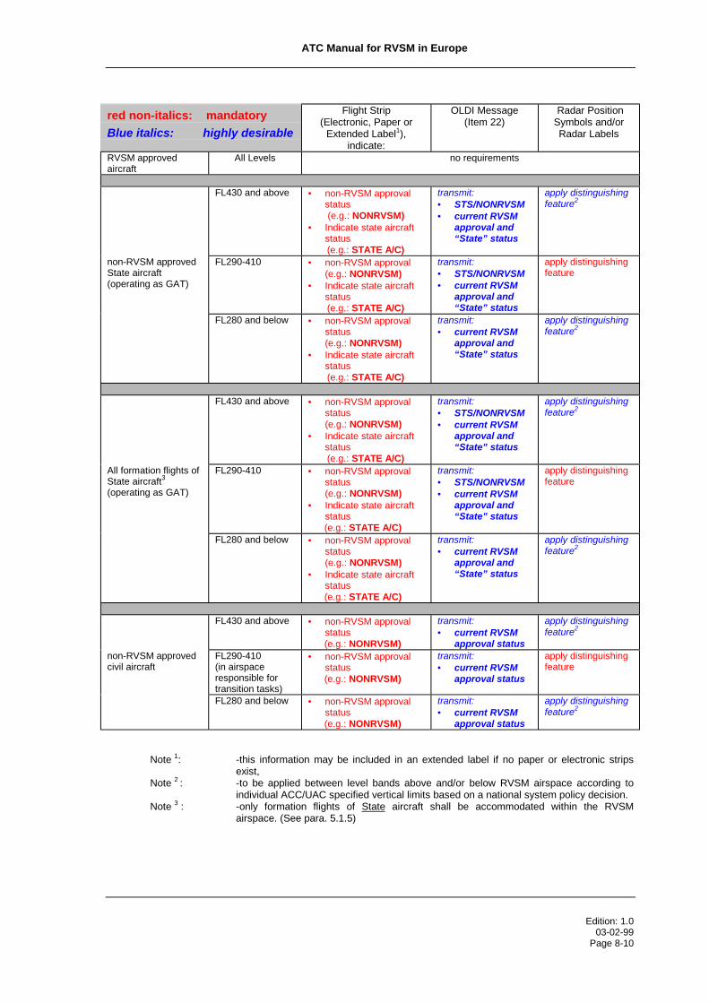
ATC Manual for RVSM in Europe
Edition: 1.003-02-99
Page 8-10
red non-italics: mandatory
Blue italics: highly desirable
Flight Strip(Electronic, Paper or
Extended Label1),indicate:
OLDI Message(Item 22)
Radar PositionSymbols and/orRadar Labels
RVSM approvedaircraft
All Levels no requirements
FL430 and above • non-RVSM approvalstatus
(e.g.: NONRVSM)• Indicate state aircraft
status (e.g.: STATE A/C)
transmit:• STS/NONRVSM• current RVSM
approval and“State” status
apply distinguishingfeature2
non-RVSM approvedState aircraft(operating as GAT)
FL290-410 • non-RVSM approval (e.g.: NONRVSM)• Indicate state aircraft
status (e.g.: STATE A/C)
transmit:• STS/NONRVSM• current RVSM
approval and“State” status
apply distinguishingfeature
FL280 and below • non-RVSM approvalstatus
(e.g.: NONRVSM)• Indicate state aircraft
status (e.g.: STATE A/C)
transmit:• current RVSM
approval and“State” status
apply distinguishingfeature2
FL430 and above • non-RVSM approvalstatus
(e.g.: NONRVSM)• Indicate state aircraft
status (e.g.: STATE A/C)
transmit:• STS/NONRVSM• current RVSM
approval and“State” status
apply distinguishingfeature2
All formation flights ofState aircraft3
(operating as GAT)
FL290-410 • non-RVSM approvalstatus
(e.g.: NONRVSM)• Indicate state aircraft
status (e.g.: STATE A/C)
transmit:• STS/NONRVSM• current RVSM
approval and“State” status
apply distinguishingfeature
FL280 and below • non-RVSM approvalstatus
(e.g.: NONRVSM)• Indicate state aircraft
status (e.g.: STATE A/C)
transmit:• current RVSM
approval and“State” status
apply distinguishingfeature2
FL430 and above • non-RVSM approvalstatus
(e.g.: NONRVSM)
transmit:• current RVSM
approval status
apply distinguishingfeature2
non-RVSM approvedcivil aircraft
FL290-410(in airspaceresponsible fortransition tasks)
• non-RVSM approvalstatus
(e.g.: NONRVSM)
transmit:• current RVSM
approval status
apply distinguishingfeature
FL280 and below • non-RVSM approvalstatus
(e.g.: NONRVSM)
transmit:• current RVSM
approval status
apply distinguishingfeature2
Note 1: -this information may be included in an extended label if no paper or electronic stripsexist,
Note 2 : -to be applied between level bands above and/or below RVSM airspace according toindividual ACC/UAC specified vertical limits based on a national system policy decision.
Note 3 : -only formation flights of State aircraft shall be accommodated within the RVSMairspace. (See para. 5.1.5)
ATC Manual for RVSM in Europe
Edition: 1.003-02-99
Page 8-11
8.7 STCA/MTCD
Short Term Conflict Alert - STCA
8.7.1 STCA systems of ACCs/UACs applying RVSM should be able to selectively
assess the applicable VSM of either 1 000 ft or 2 000 ft, as determined by the
current RVSM approval or non-approval status of the aircraft concerned, operating
in the level band FL 290 - FL 410 inclusive.
8.7.2 Where the STCA system of a ACC/UAC applying RVSM does not meet the
requirements of para. 4.1, it shall be able to assess a VSM of 1 000 ft up to and
including FL 410.
The serious disruptions to those operational environments applying RVSM, caused
by STCA systems generating alerts based on an assessment of a VSM of 2 000 ft
in the level band FL 290 - FL 410 inclusive, would be too numerous to be
sustainable.
ACCs/UACs will be aware, for those STCA systems not adapted to meet the
requirement described in para. 8.7.1 above, that alerts for those encounters
involving at least one non-RVSM approved aircraft, operating in the level band FL
290 - FL 410 inclusive, would be based on a VSM which would not be applicable to
the encounter in question. Nevertheless, in keeping with the concept of STCA as a
safety net, alerts would however be generated as a function of a VSM assessment
sufficient to assist in the prevention of collision avoidance.
Medium Term Conflict Detection - MTCD
8.7.3 MTCD systems of the ACCs/UACs applying RVSM shall be able to assess the
selective application of a VSM of either 1 000 ft or 2 000 ft, as determined by the
current RVSM approval or non-approval status of the aircraft concerned, operating
in the level band FL 290 - FL 410 inclusive.

ATC Manual for RVSM in Europe
Edition: 1.003-02-99
Page 8-12
8.7.4 Individual ACCs/UACs should undertake early planning to ensure that the
necessary software adaptations are accomplished within the defined timeframes
for the initial implementation of RVSM. Implementation of RVSM prior to the
completion of the necessary adaptations to STCA/MTCD systems would result in
nuisance alerts to be generated to an extent that severe operational disruptions
could result.
----Intentionally Left Blank---

ATC Manual for RVSM in Europe_______________________________________________________________________________________
Edition: 1.003-02-99Page 9-1
9. ATC CONSIDERATIONS
The introduction of RVSM will require that individual ACCs/UACs undertake a
critical evaluation of operating practises so as to identify areas where adjustments
or changes are required.
Individual ACCs/UACs may well wish to take the opportunity to maximise the
operational benefits to be gained from the introduction of RVSM by undertaking an
extensive critical operational analysis of the following:
9.1 Inter-Centre Letters of Agreement
9.1.1 The introduction of RVSM will require that individual ACCs/UACs re-evaluate their
existing letters of agreement for the purpose of optimising transfer of control
agreements through the stipulation of new optimal levels to be used for the
transfer of control of aircraft between ACCs/UACs (EUROCONTROL Common
Format Letter of Agreement, Annex D refers).
9.1.2 ACCs/UACs are advised to consider the incorporation into their letters of
agreement with adjacent ACCs/UACs descriptions of “contingency FLAS” which
could be applied during periods of meteorological conditions requiring a reversion
to a 2 000 ft vertical separation minimum. In this way, co-ordination of levels
appropriate to the transfer of traffic requiring a minimum 2 000 ft vertical
separation minimum from adjacent ACCs/UACs can be facilitated. (See para.
5.5.4, Contingency procedures)
9.1.3 Individual ACCs/UACs may consider the requirement for stipulating increased pre-
notification time parameters for the passing of estimate messages involving non-
RVSM approved aircraft intending to operate within the RVSM airspace, as a
means of facilitating planning for the integration of such traffic in accordance with a
2 000 ft VSM.
9.1.4 ACCs/UACs should consider stipulating precise co-ordination procedures related
to RVSM within their LoAs with those ACCs/UACs which do not receive flight plan
information from IFPS, so as to ensure that the individual RVSM approval status of
each individual flight is accurately communicated.

ATC Manual for RVSM in Europe
Edition: 1.003-02-99Page 9-2
9.2 Flight Level Allocation Schemes
The introduction of RVSM will permit an optimisation of existing agreed FLAS
through the designation of new flight levels for specified ATS route segments.
Strategic de-confliction of major crossing points will as well be facilitated through
the availability of additional flight levels available for use within newly defined
agreed FLAS. Also, FLAS for and adjacent to airspace where transition tasks are
carried out could be considered.
9.3 Sectorisation
9.3.1 The implementation of RVSM may require an analysis of the optimal levels to be
used for delineating the vertical limits of control sectors within ACCs/UACs.
Operational experts concerned should evaluate the requirement to re-define such
vertical limits as a function of adaptations to FLAS or predicted changes in the
vertical profiles of major traffic flows expected from the introduction of RVSM.
9.3.2 Consideration should as well be given to the impact on inter-sector co-ordination
workload resulting from the requirement for ATC to provide a 2 000 ft vertical
separation minimum to non-RVSM approved State aircraft operating as GAT within
the RVSM airspace at levels situated immediately above or below those vertical
sector boundaries defined by levels situated within the RVSM airspace. For this
situation, all sectors vertically adjacent will require continuous awareness of the
presence of such a flight through inter-sector co-ordination so as to ensure the
required vertical separation. As an example, consideration could be given to
adjusting the lower limit of a sector from FL 300 to FL 285 with the implementation
of RVSM, so as to mitigate the impact on co-ordination requirements for flights of
non-RVSM approved State aircraft operating within the RVSM airspace.
9.3.3 The implementation of RVSM will render those flight levels, in the level band
FL 290-FL 410 inclusive, which were designated as representing the vertical limits
of sectors prior to RVSM implementation, as usable flight levels. As a

ATC Manual for RVSM in Europe
Edition: 1.003-02-99Page 9-3
consequence ACCs/UACs will be required to designate vertical sector limits based
on 500 ft interval situated between two usable flight levels.
e.g.: Prior RVSM implementation, upper limit of sector: FL300
After RVSM implementation, upper limit of sector: FL295
9.3.4 ACCs/UACs may wish to consider the designation of FL 275 as a suitable division
flight level between two sectors. Such designation would make available, to the
sector responsible for RVSM airspace, a “non-RVSM level” (FL 280) for use by an
aircraft experiencing an equipment related contingency.
9.3.5 As a consequence of having defined new vertical sector limits in response to the
implementation of RVSM, Areas of Common Interest (ACIs) described in letters of
agreement must be amended.
9.4 Optimisation of the ATS Route Structure
9.4.1 It is expected that the optimisation of the existing route network, after the
implementation of RVSM, will be realised through a combination of FLAS,
sectorisation and to a lesser extent changes to the en-route structure. In general, it
is expected that after the implementation of RVSM there will be a vertical
redistribution of traffic with more flights reaching a Flight Level close to their
optimum. The redistribution of flights in the airspace above FL 290 may well
require changes to the boundaries of sectors to balance workload, particularly in
areas where there are a number of horizontal sector boundaries above FL 290. It
is also expected that the application of a FLAS at the confluence of major routes or
at heavily loaded crossing points could have a beneficial affect on capacity. For
optimal benefit, such FLASs will need to be coordinated on a Europe wide basis.
These changes will, by and large, be accommodated within the Version 3 route
network. However, there may be instances where due to traffic levels or specific
local demands, changes to the route network will be required.
9.4.2 On bi-directional routes, traffic climbing or descending to/from cruise will need to
cross more Flight Levels than is currently the case. Therefore, consideration
should be given to the potential benefit of extending the uni-directional route

ATC Manual for RVSM in Europe
Edition: 1.003-02-99Page 9-4
system. Local needs (e.g. availability of airspace, sectorisation, crossing points )
will dictate whether or not this is practicable but on those segments where the
majority of the traffic is in the evolutionary stages of flight, the creation of
specialised one way routes, ideally permitting climb/descent to/from cruise, could
decrease controller workload and maximise capacity.
9.4.3 States on the periphery of the proposed RVSM area are faced with different ATC
tasks to States within the RVSM core area. These States may wish to evaluate the
potential increase in controller workload on busy uni-directional routes that cross
the proposed RVSM/non-RVSM boundary. Controllers will need to adjust the Flight
Level on most aircraft entering and exiting the RVSM area. This task is
complicated by the disparity between the two VSMs (Conventional outside the
RVSM area and RVSM within) which results in the situation where traffic operating
at three FLs, FL 310, 350 and 390 will be in opposite direction, same level at the
eastern RVSM boundary. States may wish to consider the option of creating a uni-
directional route network at the RVSM/non-RVSM boundary if the traffic levels or
complexity of tasks are sufficiently high to warrant a structural solution. This could
be achieved either cross border after co-ordination with neighbouring non-RVSM
States or if necessary within the FIR of an individual State.

ATC Manual for RVSM in Europe_______________________________________________________________________________________
Edition: 1.003-02-99
Page 10-1
10. ACAS
The provisions of ICAO Doc. 7030, European (EUR) Regional Supplementary
Procedures, Chapter 16: “Use of Airborne Collision Avoidance System (ACAS)”,
will render mandatory the carriage and operation of ACAS II in the EUR Region
(including FIR Canarias) for specified aircraft from 01-January-2000.
It is relevant to note that the current state of ACAS operations, globally, is
represented, for the most part, by the operation of TCAS II, Version 6.04A, on an
either mandatory or voluntary basis. Equally relevant, is the fact that the
aforementioned Version 6.04A of TCAS II is not ICAO ACAS SARPs compliant.
The operation of such a version of a TCAS II system would not, therefore, satisfy
those EUR ACAS provisions described above.
The TCAS II Version 6.04A thresholds, for issuing Traffic Advisories (TAs) and
Resolution Advisories (RAs), were designed for an environment with standard
vertical separation, above FL 290, of 2 000 ft. Analysis of TCAS II Version 6.04A
performance has revealed that, in an RVSM environment, the system would be
operationally incompatible - this is not to suggest that it is unsafe. Operational
experience in the North Atlantic Region has confirmed that TCAS II Version 6.04A
poses some significant operational issues. The upgrade of TCAS II Version 6.04A
to Version 7 includes modifications to address operational issues and to improve
the compatibility in RVSM (other modifications are expected to improve TCAS II
operations in other respects).
The ECAC RVSM traffic environment will be more complex and dense than that on
the North Atlantic. Comprehensive work is underway to confirm TCAS II Version 7
performance in the ECAC RVSM environment. Initial analysis indicates that the
modifications introduced are effective, and it is considered important that
TCAS II Version 7 should be in widespread use before the ECAC RVSM system is
implemented.
The implementation of RVSM will not bring about changes to ATC procedures
relating to ACAS (PANS-RAC, Part II). Nevertheless, controllers are to be aware,

ATC Manual for RVSM in Europe
Edition: 1.003-02-99
Page 10-2
that notwithstanding the EUR ACAS provisions referred to above, there shall
remain a probability that a small population of aircraft may continue to operate in
the European RVSM airspace while operating either TCAS II, Version 6.04A or no
ACAS system, by virtue of the fact that they are not included in the aircraft
selection criteria of the EUR ACAS Provisions, i.e.: civil, fixed-wing turbine aircraft
of more than 15 000 kg or maximum passenger load of more than 30. Safety
studies initiated by EUROCONTROL are currently underway which will seek to
define, among other issues, the impact which aircraft so equipped will pose to the
RVSM operational environment. The implementation of RVSM is being undertaken
with due regard for the for the operational performance of ACAS II. As indicated in
the EUR ACAS Provisions, the mandatory use of ACAS II in Europe precedes the
implementation of RVSM in Europe.
---END---

ATC Manual for RVSM in Europe_______________________________________________________________________________________
Edition: 1.003-02-99Page A-1
Appendix ARVSM Table of Cruising Levels
(Reference: ICAO Annex 2, Appendix 3, Paragraph a))
IFR VFR
FL430
FL410
FL400
FL390
FL380
FL370
FL360
FL350
FL340
FL330
FL320
FL310
FL300
FL290FL285
FL280FL275
IFR Cruising Level for Tracks 000° - 179° (or 090° - 269°in theFIRs/UIRs of Italy, France, Portugal and Spain)
IFR Cruising Level for Tracks 180° - 359° (or 270° - 089° in theFIRs/UIRs of Italy, France, Portugal and Spain)
VFR Cruising Level for Tracks 000° - 179° (or 090° - 269° inthe FIRs/UIRs of Italy, France, Portugal and Spain)
VFR Cruising Level for Tracks 180° - 359° (or 270° - 089° inthe FIRs/UIRs of Italy, France, Portugal and Spain)
note: The provisions of ICAO Annex 2 preclude VFR flight aboveFL 290. Accordingly, attention is drawn to the absence of VFRcruising levels above FL410, where the VSM reverts to2 000 ft.

ATC Manual for RVSM in Europe_______________________________________________________________________________________
Edition: 1.003-02-99Page B-1
Appendix BRVSM/non-RVSM Transition
non-RVSM RVSM non-RVSM
FL430 FL430
FL410 FL410 FL410
FL400
FL390 FL390 ¤ FL390
FL380
FL370 FL370 FL370
FL360
FL350 FL350 ¤ FL350
FL340
FL330 FL330 FL330
FL320
FL310 FL310 ¤ FL310
FL300
FL290 FL290 FL290
FL280 FL280 FL280
¤ conflict to be resolved during transition
Tracks 000° - 179° (or 090° - 269° in the FIRs/UIRs ofItaly, France, Portugal and Spain)
Tracks 180° - 359° (or 270° - 089° in the FIRs/UIRs ofItaly, France, Portugal and Spain)

ATC Manual for RVSM in Europe
Edition: 1.003-02-99Page C-1
Appendix C
Feet - Metric Transition
Metric*Area
RVSMArea
Metric*Area
13,100 m(42,978 ft)
FL430 13,100 m(42,978 ft)
������������������������������������������������������������������������������������ FL410
������������������������������������������������������������������������
12,100 m(39,698 ft)
������������������������������������������������������������������������������������
FL400
������������������������������������������������������������������������
12,100 m(39,698 ft)���������������������
���������������������������������������������������������������
FL390
������������������������������������������������������������������������
11,600 m(38,057 ft)
��������������������������������������������������������������� FL380
������������������������������������������������������ 11,600 m
(38,057 ft)11,100 m(36,417 ft)
������������������������������������������������������������������������������������ FL370
������������������������������������������������������������������������ 11,100 m
(36,417 ft)������������������������������������������������������������������������������������
FL360
������������������������������������������������������������������������
10,600 m(34,776 ft)
������������������������������������������������������������������������������������
FL350
������������������������������������������������������������������������
10,600 m(34,776 ft)���������������������
������������������������������������������ FL340������������������������������������������������������
10,100 m(33,136 ft)
������������������������������������������������������������������������������������ FL330
������������������������������������������������������������������������ 10,100 m
(33,136 ft)
9,600 m
������������������������������������������������������������������������������������
FL320
������������������������������������������������������������������������ 9,600 m
(31,496 ft)
������������������������������������������������������������������������������������
FL310
������������������������������������������������������������������������
(31,496 ft)
9,100 m(29,855 ft)
������������������������������������������������������������������������������������
FL300������������������������������������������������������������������������
9,100 m(29,855 ft)������������������������������������������
��������������������� FL290������������������������������������������������������
8,600 m(28,214 ft)
FL280 8,600 m(28,214 ft)
* system of metric cruising levels as applied, for instance, in theRussian Federation
Tracks 000° - 179° (or 090° - 269° in the FIRs/UIRs of Italy,France, Portugal and Spain)
Tracks 180° - 359° (or 270° - 089° in the FIRs/UIRs of Italy,France, Portugal and Spain)
Airspace where Transition Tasks are carried out
Appendix D

ATC Manual for RVSM in Europe
Edition: 1.003-02-99
Page D-2
Following is an extract of the relevant section (Part 3) of the ICAO Document “Guidance
Material on the Implementation of a 300m (1000ft) Vertical Separation Minimum in the
European RVSM Airspace”: Airworthiness
It is intended as a means of providing background material of sufficient detail to allow
operational ATC personnel to gain an appreciation of the subject. The contents of this
appendix, therefore should not be considered as authoritative.
AIRWORTHINESS
Introduction
This material has been prepared in conjunction with the Joint Airworthiness Authority (JAA) and
it provides an overview of the development, and content, of JAA Temporary Guidance Leaflet
(TGL) No.6. which is the authoritative document on all issues relating to the European MASPS
and on the approval of aircraft and operators for flight in designated RVSM airspace.
Background
1 The initial MASPS, for the height keeping accuracy necessary for RVSM operations,
was established by the ICAO RGCSP. It was further refined by the NAT SPG by means
of a group of technical specialists from State authorities, aircraft and avionics
manufacturers, and airline and pilot associations. This group developed material which
was then published by the Federal Aviation Administration (FAA) as FAA Document 91
- RVSM : Interim Guidance for Approval of Operators/Aircraft for RVSM Operations,
and by the JAA as Information Leaflet No. 23 (I.L.No. 23). These documents detailed
the airworthiness, continuing airworthiness, and operations programmes necessary to
approve operators and aircraft for RVSM operations in the NAT RVSM airspace.
2 JAA TGL No.6

ATC Manual for RVSM in Europe
Edition: 1.003-02-99PageD-3
2.1 JAA TGL No.6 was published in mid 1998. It extends the area of applicability of the
requirements of I.L. No. 23, to any region in which RVSM operations are introduced.
Regional differences ( e.g. ATC Procedures) are addressed in separate Annexes to the
main body of TGL No.6, which will ultimately be re-issued as a JAA Acceptable Means
of Compliance (AMC) with Joint Aviation Requirements (JAR Ops 1 Subpart L). The
requirements detailed in the main body of TGL No.6 are unchanged from those set out
in IL No. 23. which were developed in accordance with the conclusions of the
RGCSP/6 Meeting (Doc 9536).
TGL No.6 provides detailed guidance on :
• the process for the approval of Aircraft and Operators, for RVSM operations.
• RVSM performance requirements
• Aircraft System requirements
• Airworthiness Approval
• Continued Airworthiness (Maintenance Requirements)
• Operational Approval (ATC and Flight Crew) aspects.
together with the following Appendices :
Appendix 1 - Explanation of W/δ
Appendix 2 - Altimetry System Error (ASE) Components
Appendix 3 - Establishing and Monitoring Static Source Errors
Appendix 4 - Training Programmes and Operating Practices and Procedures
Appendix 5 - Review of ICAO Doc.9574 - Height Keeping Errors
Appendix 6 - Specific Procedures [ATC] for European RVSM Airspace
Appendix 7 - Specific Procedures for the North Atlantic Airspace
TGL No.6 Para 8 details the following minimum equipment fit for aircraft seeking
airworthiness approval for RVSM operations :
a) Two independent altitude measurement systems. Each system will need to be
composed of the following elements:
• Cross-coupled static source/system, provided with ice protection if located in
areas subject to ice accretion;

ATC Manual for RVSM in Europe
Edition: 1.003-02-99
Page D-4
• Equipment for measuring static pressure sensed by the static source,
converting it to pressure altitude and displaying the pressure altitude to the
flight crew:
• Equipment for providing a digitally coded signal corresponding to the
displayed pressure altitude, for automatic altitude reporting purposes;
• Static source error correction (SSEC), if needed to meet the performance
criteria.
• Signals referenced to a pilot selected altitude for automatic control and
alerting. These signals should be derived from an altitude measurement
system meeting the criteria of this document [TGL No. 6], and, in all cases,
enabling the criteria relating to Altitude Control Output and Altitude Alerting to
be met.
b) One Secondary Surveillance Radar (SSR) transponder with an altitude
reporting system that can be connected to the altitude measurement system
in use for altitude for height keeping.
c) An altitude alerting system
d) An automatic altitude control system.

ATC Manual for RVSM in Europe
Edition: 1.003-02-99Page E-1
Appendix E
Following is an extract of the relevant section (Part 4), State Approval of Aircraft for RVSM
Operations, of the ICAO Document: “Guidance Material on the Implementation of a 300m
(1000ft) Vertical Separation Minimum in the European RVSM Airspace”.
It is intended as a means of providing background material, of sufficient detail, to allow
operational ATC personnel to gain an appreciation of the subject. The contents of this
appendix, therefore should not be considered as authoritative.
STATE APPROVAL OF AIRCRAFT FOR RVSM OPERATIONS
1 The State Approval Process
1.1. With effect from the agreed date of the implementation of RVSM in European airspace,
Operators intending to conduct flights within the notified RVSM airspace shall require
an RVSM Approval either from the State in which the aircraft is registered, or from
the State in which the Operator is based. Whilst the primary responsibility for gaining
the necessary approval must rest with the aircraft operator, State aviation authorities
will be expected to initiate such procedures as necessary to publicise the requirement
for, and the means of obtaining, such approvals. In addition, State aviation authorities
should maintain regular checks and records of the approvals which they have granted,
and ensure that the relevant data is passed to the designated central data base.
2 RVSM Approvals. An RVSM approval will encompass the following elements:
2.1 Airworthiness Requirements (including continuous airworthiness)
2.1.1 The European RVSM Airworthiness requirements are detailed in the JAA TGL No 6.
Para. 9. This provides guidance for the approval of newly built aircraft and for aircraft
that have already in service. Aircraft may be granted an airworthiness approval against
these requirements, or those of equivalent State documentation.

ATC Manual for RVSM in Europe
Edition: 1.003-02-99Page E-2
2.1.2 State Airworthiness authorities should also confirm that aircraft altimetry and height-
keeping equipment will be maintained in accordance with approved procedures and
servicing schedules as detailed in TGL No 6 Para 10.
2.1.3 Whilst meeting the airworthiness requirements of an RVSM approval is, by itself, not
sufficient to authorise flight in RVSM airspace, it will qualify the aircraft to enter the
Airspace User Preparation & Performance Verification Phase (P1) of the monitoring
programme. It is important therefore that the appropriate State Authority should advise
the designated monitoring cell accordingly.
2.2 Operational Requirements
2.2.1 To meet the operational requirements of an RVSM approval, the operator will need to
satisfy the appropriate authority that that they have instituted flight crew procedures
for operations in the European RVSM airspace.
3. Content of Operator RVSM Application
3.1 The required content of an Operator’s application for RVSM approval is detailed in TGL
No.6 Para 11.3, and summarised below. The application should be submitted in
sufficient time to permit evaluation before the intended start of RVSM operations and
should include :
• Airworthiness Documents - to show that the aircraft holds an RVSM airworthiness
approval
• Description of Aircraft Equipment - appropriate to RVSM operations
• Training Programmes and Operating Practices and Procedures - holders of Air
Operators Certificates (AOC) should submit training syllabi and other appropriate
material to the responsible authority to show that the operating practices, procedures
and training items related to RVSM operations are incorporated in initial, and where
appropriate, recurrent training programmes. Other operators will need to comply with
local procedures to satisfy the responsible authority that their knowledge of RVSM

ATC Manual for RVSM in Europe
Edition: 1.003-02-99Page E-3
operating procedures and practices is equivalent to that set for AOC Holders,
sufficient to hold approval to conduct RVSM operations. Guidance on the content of
Flight Crew training programmes and operating practices and procedures is given in
Section 5 of this document. This material is identical to Appendix 4 of TGL No.6. The
European RVSM ATC Procedures which are set out in Section 6 of this document
are copied in Appendix 6 to TGL No.6.
• Operations Manuals and Checklists - the appropriate manuals and checklists should
be revised to include information/guidance on standard operating procedures for
RVSM operations.
• Past Performance - relevant operating history, where available, should be included in
the application. The applicant should show that changes needed in training, operating
or maintenance practices to improve poor height keeping performance, have been
made.
• Minimum Equipment List (MEL) - where applicable, an MEL, adapted from the Master
Minimum Equipment List (MMEL) and relevant operational regulations, should
include items pertinent to operating in RVSM airspace.
• Maintenance - when application is made for operational approval, the operator should
establish a maintenance programme acceptable to the responsible authority.
• Plan for participation in the Performance Verification/Monitoring Programmes - this
plan will need to include, as a minimum, a check on a sample of the operators fleet
by an independent height monitoring system.
3 The application of the RVSM approval process and the monitoring programmes may
be sufficient to verify the height keeping performance of an aircraft. However, the
final step of the approval process may require a demonstration flight. The
responsible authority may appoint an inspector for a flight in RVSM airspace to verify
that all procedures are applied effectively. If the performance is satisfactory, the
operator will be eligible for RVSM approval.
4 Issue of RVSM Approval.

ATC Manual for RVSM in Europe
Edition: 1.003-02-99Page E-4
• For AOC Holders - approvals will be issued by the appropriate authority in
accordance with Joint Airworthiness Requirements (JAR OPS 1). Each aircraft group
for which the operator is granted approval will be listed in the Approval.
• For Non AOC Holders - these operators will be issued with an Approval as required
by national regulations or with JAR OPS 2 when this is published. These approvals
will be valid for a period specified in National Regulations, typically 2 years, and may
require renewal.
5 Suspension or Revocation of Approval for RVSM Operations.
5.1 The incidence of height keeping errors that can be tolerated in an RVSM environment
is small. Thus Operators will be expected to take immediate action to rectify the
conditions which cause an error. The operator should report an occurrence involving
poor height keeping to the responsible authority within 72 hours. The report should
include an initial analysis of causal factors and measures taken to prevent any
reoccurrence. The need for follow up reports will be determined by the responsible
authority.
5.2 Occurrences that should be reported and investigated are height keeping errors
which display a :
• TVE equal to or greater than 300 ft (90m)
• ASE equal to or greater than 245 ft (75m)
• AAD equal to or greater than 300 ft (90m)
5.3 An Operator that consistently experiences height keeping errors, whether they are due
to technical or operational causes, will have approval for RVSM operations revoked. If a
problem is related to one specific aircraft type, then RVSM operational approval may be
revoked for that specific type within the Operator’s fleet. If an Operator’s response to a
notification of an height keeping error is not timely or effective, then the relevant
authority may consider suspending or revoking RVSM approval.
6 Provision for the monitoring of aircraft:
ATC Manual for RVSM in Europe
Edition: 1.003-02-99Page E-5
6.1 A programme to monitor or verify aircraft height-keeping performance is considered a
necessary element of European RVSM implementation. Verification and monitoring
programmes have the basic objective of observing and evaluating the height-keeping
performance of MASPS equipped aircraft to :
a) confirm the efficacy of the RVSM MASPS
b) monitor the effectiveness of the approval process.
c) confirm that required safety levels will be achieved when RVSM is implemented.
7 Data base of State approvals
7.1 State aviation authorities will be expected to maintain a State Data Base (SDB) of all
approvals which they have granted for operations in RVSM airspace. The details of the
compilation and formatting of the data and the system operating parameters are under
development. Ideally, the SDBs will provide data to one or more Central Data Bases
(CDBs), including the NAT Central Monitoring Agency (CMA). This would facilitate the
tactical monitoring of the approval status of those aircraft which have flight planned to
operate in RVSM airspace, should such monitoring be considered necessary.

ATC Manual for RVSM in Europe
Edition: 1.003-02-99Page F-1
Appendix F
Following is an extract of the relevant section (Parts 5) of the ICAO Document “Guidance
Material on the Implementation of a 300m (1000ft) Vertical Separation Minimum in the
European RVSM Airspace”: Flight Crew Training Programmes and Operating Practices and
Procedures
It is intended as a means of providing background material of sufficient detail to allow
operational ATC personnel to gain an appreciation of the subject. The contents of this
appendix, therefore should not be considered as authoritative.
FLIGHT CREW TRAINING PROGRAMMES AND OPERATING PRACTICES AND
PROCEDURES
1. Introduction
1.1 Flight crews will need to have an awareness of the criteria for operating in RVSM
airspace and be trained accordingly. The items detailed in paragraphs 2 to 6 should
be standardised and incorporated into training programmes and operating practices
and procedures. Certain items may already be adequately standardised in existing
procedures. New technology may also remove the need for certain actions required
of the flight crew. If this is so, then the intent of this guidance can be considered to be
met.
Note: This guidance material has been developed for all users of RVSM airspace,
and as such is designed to present all required actions. It is recognised that
some material may not be necessary for larger public transport operators.
2. Flight Planning
2.1 During flight planning the flight crew should pay particular attention to conditions that
may affect operation in RVSM airspace.

ATC Manual for RVSM in Europe
Edition: 1.003-02-99Page F-2
2.1.1 These include, but may not be limited to:
• verifying that the airframe is approved for RVSM operations;
• reported and forecast weather on the route of flight;
• minimum equipment requirements pertaining to height keeping and alerting
systems; and
• any airframe or operating restriction related to RVSM approval.
3. Pre-flight procedures at the aircraft for each flight
3.1 The following actions should be accomplished during the pre-flight procedure:
• review technical logs and forms to determine the condition of equipment required
for flight in the RVSM airspace. Ensure that maintenance action has been taken to
correct defects to required equipment;
• during the external inspection of aircraft, particular attention should be paid to the
condition of static sources and the condition of the fuselage skin near each static
source and any other component that affects altimetry system accuracy. This
check may be accomplished by a qualified and authorised person other than the
pilot (e.g. a flight engineer or ground engineer);
• before takeoff, the aircraft altimeters should be set to the QNH of the airfield and
should display a known altitude, within the limits specified in the aircraft operating
manuals. The two primary altimeters should also agree within limits specified by
the aircraft operating manual. An alternative procedure using QFE may also be
used. Any required functioning checks of altitude indicating systems should be
performed.
• Note. The maximum value for these checks cited in operating manuals should not
exceed 23m (75 ft).
• before take-off, equipment required for flight in RVSM airspace should be
operative, and any indications of malfunction should be resolved.
4. Procedures prior to RVSM airspace entry
4.1 The following equipment should be operating normally at entry into RVSM airspace:
• Two primary altitude measurement systems.
• One automatic altitude-control system.
• One altitude-alerting device.

ATC Manual for RVSM in Europe
Edition: 1.003-02-99Page F-3
Note: Dual equipment requirements for altitude-control systems will be established
by regional agreement after an evaluation of criteria such as mean time
between failures, length of flight segments and availability of direct pilot-
controller communications and radar surveillance.
• Operating Transponder. An operating transponder may not be required for entry
into all designated RVSM airspace. The operator should determine the
requirement for an operational transponder in each RVSM area where operations
are intended. The operator should also determine the transponder requirements
for transition areas next to RVSM airspace.
Note: Should any of the required equipment fail prior to the aircraft entering
RVSM airspace, the pilot should request a new clearance to avoid
entering this airspace;
5 In-Flight Procedures
5.1 The following practices should be incorporated into flight crew training and
procedures:
• Flight crews will need to comply with any aircraft operating restrictions, if
required for the specific aircraft group, e.g. limits on indicated Mach number,
given in the RVSM airworthiness approval.
• Emphasis should be placed on promptly setting the sub-scale on all primary
and standby altimeters to 1013.2 (hPa) /29.92 in. Hg when passing the
transition altitude, and rechecking for proper altimeter setting when reaching
the initial cleared flight level;
• In level cruise it is essential that the aircraft is flown at the cleared flight level.
This requires that particular care is taken to ensure that ATC clearances are
fully understood and followed. The aircraft should not intentionally depart from
cleared flight level without a positive clearance from ATC unless the crew are
conducting contingency or emergency manoeuvres;

ATC Manual for RVSM in Europe
Edition: 1.003-02-99Page F-4
• When changing levels, the aircraft should not be allowed to overshoot or
undershoot the cleared flight level by more than 45 m (150 ft);
Note: It is recommended that the level off be accomplished using the altitude
capture feature of the automatic altitude-control system, if installed.
• An automatic altitude-control system should be operative and engaged during
level cruise, except when circumstances such as the need to re-trim the
aircraft or turbulence require disengagement. In any event, adherence to
cruise altitude should be done by reference to one of the two primary
altimeters. Following loss of the automatic height keeping function, any
consequential restrictions will need to be observed.
• Ensure that the altitude-alerting system is operative;
• At intervals of approximately one hour, cross-checks between the primary
altimeters should be made. A minimum of two must agree within ±200 ft
(±60 m). Failure to meet this condition will require that the altimetry system be
reported as defective and notified to ATC;
the usual scan of flight deck instruments should suffice for altimeter cross-
checking on most flights.
• In normal operations, the altimetry system being used to control the aircraft
should be selected for the input to the altitude reporting transponder
transmitting information to ATC.
• If the pilot is advised in real time that the aircraft has been identified by a
height-monitoring system as exhibiting a TVE greater than ±300 ft (±90 m)
and/or an ASE greater than ±245 ft (±75 m) then the pilot should follow
established regional procedures to protect the safe operation of the aircraft.
This assumes that the monitoring system will identify the TVE or ASE within
the set limits for accuracy.

ATC Manual for RVSM in Europe
Edition: 1.003-02-99Page F-5
• If the pilot is notified by ATC of an assigned altitude deviation of 300 ft (90 m)
or more then the pilot should take action to return to cleared flight level as
quickly as possible.
5.2 Contingency procedures after entering RVSM airspace are:
5.2.1 The pilot should notify ATC of contingencies (equipment failures, weather) which
affect the ability to maintain the cleared flight level, and co-ordinate an appropriate
plan of action.
5.2.2 Examples of equipment failures which should lead to notification to ATC:
• failure of all automatic altitude-control systems aboard the aircraft;
• loss of redundancy of altimetry systems,
• loss of thrust on an engine necessitating descent; or
• any other equipment failure affecting the ability to maintain cleared flight level
5.2.3 The pilot should notify ATC when encountering greater than moderate turbulence.
5.2.4 If unable to notify ATC and obtain an ATC clearance prior to deviating from the
assigned cleared flight level, the pilot should follow the established contingency
procedures and obtain ATC clearance as soon as possible.
6. Post Flight
6.1 In making technical log entries against malfunctions in height keeping systems, the
pilot should provide sufficient detail to enable maintenance to effectively troubleshoot
and repair the system. The pilot should detail the actual defect and the crew action
taken to try to isolate and rectify the fault.
6.2 The following information should be recorded when appropriate:

ATC Manual for RVSM in Europe
Edition: 1.003-02-99Page F-6
• Primary and standby altimeter readings.
• Altitude selector setting.
• Sub-scale setting on altimeter.
• Auto-pilot used to control the aeroplane and any differences when an
alternative auto-pilot system was selected.
• Differences in altimeter readings, if alternate static ports selected.
• Use of air data computer selector for fault diagnosis procedure.
• The transponder selected to provide altitude information to ATC and any
difference noted when an alternative transponder was selected.
7 Special Emphasis Items: Flight Crew Training
7.1 The following items should also be included in flight crew training programmes:
• knowledge and understanding of standard ATC phraseology used in each
area of operations;
• importance of crew members cross checking to ensure that ATC clearances
are promptly and correctly complied with;
• use and limitations in terms of accuracy of standby altimeters in
contingencies. Where applicable, the pilot should review the application of
static source error correction/ position error correction through the use of
correction cards;
Note: Such correction data will need to be readily available on the flight
deck.

ATC Manual for RVSM in Europe
Edition: 1.003-02-99Page F-7
• problems of visual perception of other aircraft at 300m (1,000 ft) planned
separation during darkness, when encountering local phenomena such as
northern lights, for opposite and same direction traffic, and during turns; and
• characteristics of aircraft altitude capture systems which may lead to
overshoots.
• relationship between the aircraft's altimetry, automatic altitude control and
transponder systems in normal and abnormal conditions.
• any airframe operating restrictions, if required for the specific aircraft group,
related to RVSM airworthiness approval.

ATC Manual for RVSM in Europe
Edition: 1.003-02-99
Page G-1
Appendix G
Following is an extract of the relevant section (Parts 7) of the ICAO Document “Guidance
Material on the Implementation of a 300m (1000ft) Vertical Separation Minimum in the
European RVSM Airspace”: System Performance Monitoring
It is intended as a means of providing background material of sufficient detail to allow
operational ATC personnel to gain an appreciation of the subject. The contents of this
appendix, therefore should not be considered as authoritative.
SYSTEM PERFORMANCE MONITORING
1 Introduction
1.1 This Part provides guidance on the monitoring of operations in European RVSM
airspace. The objectives of the monitoring programme are to ensure that the level of
collision risk does not exceed the TLS and to assess the compliance of aircraft with
the global height keeping performance specification (paragraph 2.2 refers). This
information will be taken into account by decision makers in judging whether overall
safety goals applicable to the European RVSM airspace are being achieved.
1.2 The overall criterion for safety in the European RVSM area is that the TLS of 5 x 10⁻⁹
fatal accidents per flight hour (representing the risk due solely to the loss of vertical
separation from any cause) is not exceeded. The agreed method of assessing actual
collision risk is by the use of a variant of the Reich collision risk model (CRM) suitable
to the area.
1.3 The height-keeping errors which will contribute to collision risk in the European
RVSM area can be divided into two categories; technical errors and operational
errors. Technical errors, i.e. Altimetry System Errors (ASE) are caused by
inaccuracies in the height-keeping equipment of aircraft, whereas, operational errors,
i.e. Assigned Altitude Deviation (AAD), are caused by mistakes, by ATC or Flight
Crew, which result in aircraft being flown at incorrect flight levels. ASE and AAD are
ATC Manual for RVSM in Europe
Edition: 1.003-02-99
Page G-2
the main constituents of Total Vertical Error (TVE). As aircraft operations in the
European area are, for the larger part, conducted under tactical radar control
together with some procedural separation, the frequency of occurrence, size and
duration of operational errors can be greatly reduced. Nevertheless, operational
errors can, and do, occur and may make a significant contribution to the overall
collision risk. The TLS has been chosen to take account of the risk from both
technical errors and operational errors.
1.4 In order to ensure that the TLS is not being exceeded, it is necessary to monitor both
the occurrence of vertical errors and the CRM parameter values on a continuing
basis. Many of the parameter values used in the CRM are based on a planning
horizon of approximately 10 years and require periodic monitoring.
1.5 The CRM parameters fall into two groups from the stand-point of monitoring
requirements. The first group consists of two important parameters which are critical
for safety assessment, in the sense that the actual risk in the airspace changes in
proportion to changes in their values. The first of these parameters is an estimate of
the proportion of flight time spent by aircraft, nominally separated by 1 000 ft, in
vertical overlap. This parameter is a function of the height-keeping performance of
the overall aircraft population. It is termed the "vertical overlap probability" and
denoted by the term “Pz(1000)”. The second of these parameters is an estimate of the
number of aircraft plan overlap events per aircraft flight hour.
1.6 The second group of CRM parameters is less demanding either because the CRM is
relatively insensitive to their values, or because they are not expected to change
substantially over the planning horizon of this document. They should be re-assessed
periodically to ensure that their values reflect the current European RVSM airspace
system.
1.7 It must be emphasised that the monitoring requirements, in particular the
measurement of TVE, have been established at a stringent level appropriate to the
first application of RVSM in a complex, high density continental airspace. As a result
of initial work done in the NAT, and the additional data and operational experience
which will be gained in Europe, it may be possible in the future to relax some of the
monitoring requirements in the European area and in other regions where the RVSM
is introduced as a part of the global implementation process.

ATC Manual for RVSM in Europe
Edition: 1.003-02-99
Page G-3
1.8 All of the measures which combine to constitute, or to verify, the height-keeping
performance of an aircraft play a part in the concept of monitoring which is expected
to make a significant contribution to risk reduction. The measures include:
• the requirement for aircraft to carry and use the equipment defined in the
MASPS;
• the initial installation procedures, tests and, where necessary, flight checks of
aircraft altimetry equipment;
• the compliance with State airworthiness approval procedures;
• the compliance with continued airworthiness requirements;
• the adherence to ATC procedures; and
• the completion of in-flight operating drills by crews.
1.9 All of the foregoing measures are addressed in the relevant parts of this guidance
material. However, these measures do not give a direct indication that the overall
criterion for safety is met. This can be achieved only through independent system
performance monitoring.
2 The Collision Risk Model
2.1 The risk of a mid-air collision due to a loss of vertical separation, from any cause, will
be estimated using a CRM which is currently being adapted to meet the specific
requirements of European airspace. The model brings together factors of the
operational system, through probabilistic and deterministic elements, to produce an
estimate of the long-term average system risk of aircraft collision.
2.2 The TLS for the European RVSM airspace, of 5 x10⁻⁹ fatal accidents per flight hour,
embodies the collision risk due to the loss of vertical separation from all causes. This
represents the upper limit for the value of Naz which results when the collision risk
equation is evaluated. That is, the Naz can not be larger than the TLS.

ATC Manual for RVSM in Europe
Edition: 1.003-02-99
Page G-4
3 Monitoring the Parameters of the CRM specification
In order to ensure that the collision risk with European RVSM operations does not
exceed the TLS, the parameters of the CRM must be monitored and assessed on a
continuing basis.
3.1 MONITORING OF PZ(1 000)
3.1.1 Monitoring of height keeping performance in the European RVSM airspace
3.1.1.1 The agreed TLS of 5 x 10⁻⁹ fatal accidents per flight hour requires that an
assessment of total system vertical overlap probability (Pz(1000)) be performed.
This requires that the duration of all large errors in the vertical plane be reported and
assessed. Thus, in addition to errors detected through the height monitoring system,
all operational errors which occur in European RVSM airspace and which result in
aircraft flying at or close to a flight level other than the one to which they were
assigned, or were assigned to in error, must be reported.
3.1.1.2 The contribution of operational errors to the overall risk is not yet known but could be
high in the European area. However, because the majority of aircraft in the region are
controlled tactically using radar surveillance, it is anticipated that controller
intervention will limit or reduce the size and duration of operational errors.
Nonetheless, it is vital that reports of all operational errors should be sent by provider
States to the designated monitoring agency.
3.1.1.3 System risk is directly proportional to the amount of total flight time spent by aircraft
at an incorrect flight level. The estimates of such times will be one of the key
elements to be used in determining whether or not the system is in compliance with
the TLS, using appropriate mathematical and statistical methods.
3.1.1.4 Data sources for estimating time spent by aircraft at incorrect flight levels will include
reports to the designated monitoring agency by ATC authorities and airlines, as well
as the results of special data gathering exercises using HMUs and other suitable
systems.

ATC Manual for RVSM in Europe
Edition: 1.003-02-99
Page G-5
3.1.2 Monitoring of Compliance with the Global System Performance Specification
3.1.2.1 In addition to the requirement that total system performance meets the overall TLS,
the monitoring process will be used to ensure that the fleet of aircraft flying in the
European RVSM airspace meets the global system performance specification from
which the RVSM MASPS was derived (paragraph 2.2.3 above also refers).
3.1.2.2 Because the global system performance specification, and in particular the Pz(1000)
of 1.7 x 10⁻⁸, was used to derive aircraft height keeping performance specifications,
only errors resulting from incorrectly operating equipment are included in this aspect
of the monitoring programme.
3.1.2.3 An assessment of TVE is critical to an assessment of Pz(1 000). As a result, the
accuracy with which TVE can be measured is an important concern. TVE can be
measured by comparing the geometric height of an aircraft, as measured by an
HMU, or any other suitable system, to the geometric height of its assigned flight level.
The accuracy of the measurement should be such that the mean error is 0 ft and the
SD of the error does not exceed 50 ft.
3.1.2.4 These measured TVE data are fundamental to the monitoring process. Large
amounts of such TVE data are needed to draw inference from the monitoring process
with a high level of confidence.
3.1.2.5 Given a measured TVE and a simultaneous difference between automatically
reported Mode C altitude and assigned flight level (i.e. the AAD), it is possible to
estimate the aircraft's ASE, i.e., the difference between its TVE and AAD. Thus it is
important to obtain as much measured TVE data as possible, in order to calculate
typical ASE values for airframes and for aircraft types, before and during initial
applications of the RVSM, to determine whether these ASE values are constant and
repeatable. If this can be shown it will become possible to estimate an aircraft’s TVE
from a knowledge of the Mode C (or Mode S or ADS) altitude.
3.2 MONITORING AIRCRAFT PASSING EVENTS INVOLVING PLAN OVERLAP
3.2.1 In addition to an upper bound for Pz(1000), the original form of the global system
performance specification provided upper bounds for aircraft passing frequency and

ATC Manual for RVSM in Europe
Edition: 1.003-02-99
Page G-6
the probability of lateral overlap. These values were derived for opposite direction
traffic.
3.2.2 However, because the majority of traffic in European RVSM airspace will fly on
crossing routes and because a growing proportion of traffic is expected to be flying
direct routes in the future, the global system performance specification has been
reformulated in terms of passing events involving plan overlap.
3.2.3 The aircraft passing frequency involving plan overlap in the European area will be
assessed on a monthly basis by the designated monitoring agency using traffic data
supplied by the ATC authorities. It is anticipated that the level of this parameter may
be close to that used to derive the aircraft height-keeping performance in the global
system performance specification.
3.3 MONITORING OTHER CRM PARAMETERS
3.3.1 The remaining CRM parameters are average aircraft speed, relative speed between
aircraft, and the average length, width and height of the aircraft operating in the
European airspace. As stated previously, the risk of a mid-air collision is either
relatively insensitive to these parameter values, or the values are not expected to
change substantially over the planning horizon of this document. Intensive monitoring
of the values of these parameters should not be necessary. The designated
monitoring agency should be aware of the relative importance of these parameters in
the overall process of ensuring that system safety is maintained, and should assess
their likely values, on a periodic basis, using whatever means are deemed
appropriate.
4 Assessment of the safety of European RVSM operations
4.1 The airspace parameters which are derived from the monitoring procedures outlined
above allow the collision risk, in the vertical plane, in the airspace system to be
assessed against the TLS. The height-keeping performance of aircraft can also be
assessed and compared to the requirements of the global height-keeping performance
specification outlined in paragraph 2.2.2 above.

ATC Manual for RVSM in Europe
Edition: 1.003-02-99
Page G-7
4.2 Prior to implementation of RVSM in the European area, mathematical and statistical
techniques will be used to provide detailed information on the forecast performance of
the system in terms of collision risk and aircraft height-keeping performance. After
implementation of RVSM the monitoring of the CRM parameters and the assessment
of the system performance will continue so that any adverse trends may be quickly
identified and corrected.
4.3 During the performance verification programme, and after implementation of RVSM,
periodic reports will be issued to provide an analysis of the information obtained from
routine monitoring procedures (HMU and GMU), mandatory occurrence reports, air-
miss data, near mid-air collision reports or any other similar source of information on
aircraft height-keeping performance. The appropriate European body should take
action as necessary to ensure that the level of collision risk is maintained below the
TLS.
5 Responsibilities of the designated monitoring agency
5.1 The designated monitoring agency will be responsible for the efficient and effective
performance of the above monitoring tasks. To this end it will be necessary to :
• ensure the availability of all data required for the monitoring system,
• ensure the availability of monitoring system output,
• process the monitoring system output,
• take follow-up action after the detection of large height deviations,
• perform safety assessment.
• make recommendations to improve height keeping performance.
• issue periodic reports
6 Objectives of the Height Monitoring System
6.1 In order to recommend a monitoring system, it was necessary first to define overall
monitoring targets. Following a review of information and data collected in the vertical
studies programme and the monitoring activities in the NAT Region, it was assumed
that ASE for individual airframes would be stable for a period of two years. Two
important objectives of the Performance Verification programme (P1) were therefore

ATC Manual for RVSM in Europe
Edition: 1.003-02-99
Page G-8
to establish the ASE performance of the airframes which will operate the European
RVSM airspace and to confirm the assumptions concerning the stability of ASE.
6.2 On the basis of the above assumption, it was possible to establish the objectives of
the monitoring programme and to consider how these objectives could be met.
Firstly, the ultimate objective was to carry out a complete census of airframes. The
monitoring system should therefore be designed to be capable, in principle, of
performing such a census over a period of one year. Because a complete census
may prove to be an impractical target during the performance verification
programme, the minimum targets, listed below, were agreed. These should enable
the monitoring cell to collect sufficient information on the height keeping performance
of aircraft operating in the European Region:
6.2.1 Monitoring Targets
6.2.1.1 Monitoring targets for the Performance Verification programme for those aircraft
considered to be members of an Aircraft Group.1
6.2.1.1.1A minimum target of 60%* of the airworthiness approved airframes of each aircraft
group from each operator is required in order to generate sufficient monitoring data
to confirm whether a particular group is compliant with the MASPS.
* Note :Alternatively, this percentage may be reduced (to a minimum of 10% or 2
aircraft whichever is greater) if it can be shown, based on the ASE results,
that a sufficient number of aircraft of the same group have been sampled to
satisfy the requirement that the aircraft group meets the MASPS with a high
level of confidence.
6.2.1.1.2The method to determine whether a group1 is compliant with the MASPS, and the
organisational aspects of the application of that method, will have to be defined,
taking into account the need for a strong coherence with NAT practices.
6.2.1.1.3Any airworthiness approved group aircraft failing individual requirements (i.e. the
absolute value of ASE > 245ft ) would be deemed non-compliant. In making this
decision allowance would have to be made for the measurement error of the height
monitoring system.

ATC Manual for RVSM in Europe
Edition: 1.003-02-99
Page G-9
6.2.1.2 Monitoring targets for the Performance Verification programme for aircraft which do
not qualify as members of an aircraft group2.
6.2.1.2.1All airworthiness approved aircraft need to be monitored on an individual basis
unless flight test evidence can be provided to show that each airframe is compliant
with ASE targets.
6.2.1.2.2Any airworthiness approved aircraft failing individual requirements (i.e., the
absolute value of ASE > 200ft ) would be deemed non-compliant. In making this
decision allowance would have to be made for the measurement error of the height
monitoring system.
6.2.1.3 Use of NAT experience - After consideration of the data and experience gained in the
monitoring of the NAT RVSM operations, the following principles were adopted for
the European Region : :
• the European RVSM monitoring programme will not be part of the European
RVSM approval process for airframes. The monitoring output will only be used to
determine the go-ahead for the introduction of RVSM (P2.6).
• the number of aircraft of a particular operator which were monitored in the NAT
programme should be taken into account in determining how many aircraft of that
operator should be monitored in the European monitoring programme;
• in general, any operator-group pairings, or non-group aircraft, already satisfying
the monitoring requirements through participation in the NAT RVSM programme
would not require any further monitoring; and
• those aircraft groups, for which the reduced “10% or minimum of 2” rule is applied
in the NAT monitoring programme, will satisfy the European RVSM monitoring
requirements with that same rule.
6.2.1.4 Conclusion of Performance Verification programme - Subject to a satisfactory
collision risk assessment and other operational considerations, the introduction of
RVSM could be made provided that 90% of the flights in the area of interest would be
made by operator-aircraft group pairings or non-group aircraft that have satisfied the
monitoring requirements during the verification programme.

ATC Manual for RVSM in Europe
Edition: 1.003-02-99
Page G-10
Notes :
(1) Group aircraft are those of nominally identical design and build with respect to
all details that could influence the accuracy of height keeping performance. A
detailed explanation is given in JAA TGL No.6 Para 9.3.1.
(2) Non group aircraft are those aircraft not falling under the definition of group
aircraft.
6.3 These targets are considered to be the minimum necessary to ensure that a
representative sample of MASPS approved aircraft will be obtained. The data
obtained from a monitoring programme that meets these targets will be sufficient to
provide:
• further evidence of the stability of ASE;
• guidance on the efficacy of the MASPS and on the effectiveness of altimetry
system modifications; and
• confidence that the TLS will be met.
6.4 It is important to note that these minimum targets have been agreed on the
assumption that the observed aircraft height keeping performance would meet the
global requirements and consequently that the collision risk due to technical errors
would be less than the technical aspect of the TLS. If the observed performance
proved to be significantly worse than the global height keeping requirements, then
the minimum sampling requirements might have to be increased to determine both
the cause of the errors and whether or not the regional TLS would be threatened.
7 Description of the Height Monitoring System
1 Currently there are two accepted methods of measuring aircraft height keeping
performance. These are :
• Height Monitoring Unit (HMU). This is a fixed ground based system which employs a
network of a Master and 4 Slave Stations to receive aircraft SSR Mode A/C signals to
establish the three dimensional position of the aircraft. The geometric height of the

ATC Manual for RVSM in Europe
Edition: 1.003-02-99
Page G-11
aircraft is measured to an accuracy of 50 ft (1 Standard Deviation (SD)). This is
compared, in near real time, with meteorological input data on the geometric height
of the assigned Flight (Pressure) Level to obtain a measurement of the Total Vertical
Error (TVE) of the target aircraft. The aircraft SSR Mode C data is also recorded to
determine the extent of any Assigned Altitude Deviation (AAD) and for subsequent
aircraft identification, when the SSR Mode S response is not available.
• GPS Monitoring Unit (GMU). A GMU is a portable “box” (contained in a carry case
approximately 45 x 40 x 30 cm3) which contains a GPS receiver, a device for
recording and storing the GPS three dimensional position data, and two separate
GPS receiver antenna’s which need to be attached to aircraft windows using suction
pads. The GMU is positioned on board the candidate aircraft and, being battery
powered, functions independently of the aircraft systems. Following the flight the
recorded GPS data are sent back to a central site where, using differential post
processing, aircraft geometric height is determined. A network of not more than 25
GMUs will make up the GPS Monitoring System (GMS).
2 It is intended that the European Height Monitoring System should be a hybrid system
of HMUs and GMUs which makes optimum use of the advantages offered by each.
Thus the strategic and inflexible characteristics of the HMUs, which can provide a
large and predictable rate of collection of high quality data at relatively high
installation and low maintenance/ongoing operating costs, can be blended with the
tactical flexibility of the GMU which permits the targeting of specific aircraft at a low
initial purchase price, but with relatively high operating costs in both manpower and
logistics. The resultant system will be capable of acquiring a representative sample of
the height keeping performance of the aircraft population by operator, type or
airframe. or if required, a complete census of RVSM approved aircraft.
3 Over a period of time the HMUs will provide repeat samples of the height keeping
performance of individual aircraft. These data will establish the typical ASE range for
a variety of aircraft types and will be the basis of the studies to determine whether
the assumptions regarding the stability and repeatability of ASE are valid.
4 Those aircraft which normally operate on routes which do not pass within the
effective range of one of HMUs will be candidates for monitoring by the GMS. The

ATC Manual for RVSM in Europe
Edition: 1.003-02-99
Page G-12
GMS can also be used to obtain repeat measurements of airframes and aircraft types
which have been shown to be poor performers.
4 A combination of HMUs and a GMS is expected to provide the most efficient means
of achieving the verification and monitoring objectives. Furthermore, because of the
complementary nature of the systems, both elements (HMU/GMS) are equally critical
to the composition of the hybrid system.
5 It is currently planned that the height monitoring system for the European RVSM
airspace will consist of four HMUs, of which one (Strumble, United Kingdom) also
belongs to the NAT height monitoring system. The other three HMUs with an
extended coverage area, will be placed near Nattenheim (Germany), Geneva
(Switzerland) and Linz or Sollenau (Austria). The GMS will consist of not more than
25 GMUs, together with GPS reference stations, post-flight processing facilities and
adequate logistic support.

ATC Manual for RVSM in Europe
Edition: 1.003-02-99Page H-1
Appendix H
List of Contacts
EUROCONTROL RVSM Programme Support Office:
EUROCONTROL HQ, Brussels:
Telephone: +32 2 729 4628Fax: +32 2 729 4629
e-mail: [email protected]
EUROCONTROLrue de la Fusée, 96
B-1230 BrusselsBelgium
Name Area ofResponsibility
Tel Fax E-mail
Mr. J. SULTANA RVSM ProgrammeManager
+32 2 729 3382 +32 2 729 9003 [email protected]
Mr. J. LAMBERT Airspace Issues +32 2 729 3386 +32 2 729 9003 [email protected]
Mr. R.RAWLINGS
Airspace UserPreparation andPerformanceVerification
+32 2 729 3335 +32 2 729 9003 [email protected]
Mr. E. SERMIJN ATM Preparation +32 2 729 3473 +32 2 729 9003 [email protected]