reference 705s - soundstream · 1 reference 705s 5/3 channel power amplifier owners manual and...
TRANSCRIPT
1
REFERENCE 705s
5/3 Channel
Power Amplifier
OWNERS MANUAL AND INSTALLATION GUIDE

2
CONGRATULATIONS! You now own the REFERENCE705s Amplifier, the product of an uncompromising design and engineering philosophy. Your Soundstream REFERENCE amplifier will outperform any other amplifier in the world. To maximize the performance of your system, we recommend that you thoroughly acquaint yourself with its capabilities and features. Please retain this manual and your sales and installation receipts for future reference. Soundstream amplifiers are the result of American craftsmanship and the highest quality control standards, and when properly installed, will provide you with many years of listening pleasure. Should your amplifier ever need service or replacement due to theft, please record the following information, which will help protect your investment.
Serial # _____________________________________________ Dealer’s Name _______________________________________ Date of Purchase _____________________________________ Installation Shop ______________________________________ Installation Date ______________________________________
CAUTION! Prolonged listening at high levels may result in hearing loss. Even though your new Soundstream Reference705s sounds better than
anything you’ve ever heard, exercise caution to prevent hearing damage.

3
TABLE OF CONTENTS Features .............................................................................................................. 4 - 5 REFERENCE705s Diagram ................................................................................ 6 - 7 REFERENCE Power Supply Design ........................................................................ 8 Setting High Power/High Current ............................................................................. 9 Selecting Crossover Modes .................................................................................... 10 Selecting Input Modes ............................................................................................ 11 Setting Coherent Stereo/Bridged Mono .................................................................. 12 Wiring (with Diagram) ...................................................................................... 12 - 13 Installation and Mounting ....................................................................................... 14 Level Setting ........................................................................................................... 15 Crossover Adjustments ........................................................................................... 16 AIRBASS™ ............................................................................................................ 16 LSE.Q Subwoofer Equalization Circuitry ................................................................ 17 Sample Systems .............................................................................................. 18 - 21 Protection Circuitry & Troubleshooting ................................................................... 22 Service .................................................................................................................... 23 Specifications ......................................................................................................... 23

4
DESIGN FEATURES • Uncompromising Design and Construction including mil-spec glass epoxy circuit boards
and high current custom gold-plated solid brass connections that will accept up to 4 gauge power/ground wire.
• High Power/High Current Capability (subwoofer channel only) - Soundstream’s exclusive circuitry permits customization of your amplifier to its particular application—High Current, for ultra-low impedance loads (multiple subwoofers, less than 1 ohm) or High Power, for higher impedance loads (1 ohm and up).
• ChassisinkTM Darlington Power Array - Soundstream’s “overbuilding” of the output section incorporates multiple output transistors instead of a few for faster, stronger power delivery. The transistors are directly sandwiched between the circuit board and the heatsink in a design called ChassisinkTM to ensure cool, efficient amplifier operation.
• Staggered Asymmetrical Electronic Crossover - Continuously variable 2 or 3-way crossovers with 12 dB/octave high pass and 24 dB/octave subwoofer low pass. In 3-way mode, bandpass can be selected for midrange or midbass.
• Rear Channel De-emphasis - A circuit based on theater surround technology in which rear fill information is rolled off at 6 dB/octave with a -3 dB point at 7,000 Hz to provide a more realistic listening experience (in 5 channel mode only).
• PowerGrid Power Supply Design - All power supply components are located near one another, for the shortest possible current path and are connected by thick, wide PCB traces, which ensures rapid, high current delivery. The entire power supply is isolated on one side of the circuit board while the audio stage is located opposite it, guaranteeing minimal noise.
• Ultra-Low ESR Capacitance Bank - 24 miniature “stiffening” capacitors ensure rapid power delivery for dynamic peaks. Multiple small input power capacitors are used to provide a lower ESR (Equivalent Series Resistance), which means more power, faster.
• Smart Thermal Rollback - Most amplifiers shut off when they get too hot. In the unlikely event the Reference705s reaches 85° C, it will gradually roll back its average power (without affecting the dynamics). Once the amplifier has cooled off, it returns to full power output. If overheating should continue, a second thermal sensing protection circuit will shut off the amplifier if the heatsink reaches 95° C.
• Unregulated Power Supply - 4 ohm power ratings are measured at 12 volts, which means substantially greater output in the real world when the vehicle is running, where voltages range from 13.6 to 14.4 volts. Dynamic capability of the unregulated power supply is vastly greater than that of a tightly regulated power supply.
• Fault Monitor LED on the front panel notifies you of a blown power supply fuse.
• 1/2 Ohm Subwoofer Drive Ability - The Reference705s' subwoofer channel is designed to
5
be stable into any impedance, down to 1/2 ohm.
• Six Dual Discrete Class A Drive Stages - Over six times the drive current of most amps, which guarantees maximum performance into any load.
• Drive DelayTM Muted Turn-on/off Circuit - A unique circuit which completely eliminates amplifier-related turn-on/off noises.
• Flexible Input Sensitivity accepts voltages from 200 mV (80 mV on the subwoofer channel) to 5.0 V, which permits maximum output from the amplifier with virtually any source unit.
• Balanced Input Design for added immunity to noise caused by component and vehicle electrical system interaction.
• AIRBASS™ Upgradable - This feature allows RF wireless remote control level adjustment of
6
Reference705s
7
Key to Callouts
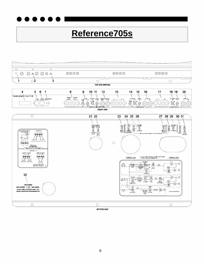
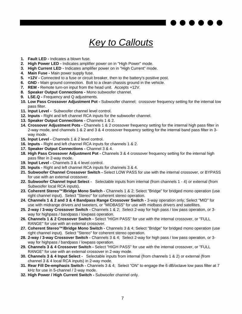
1. Fault LED - Indicates a blown fuse. 2. High Power LED - Indicates amplifier power on in "High Power" mode. 3. High Current LED - Indicates amplifier power on in "High Current" mode. 4. Main Fuse - Main power supply fuse. 5. +12V - Connected to a fuse or circuit breaker, then to the battery's positive post. 6. GND - Main ground connection. Bolt to a clean chassis ground in the vehicle. 7. REM - Remote turn-on input from the head unit. Accepts +12V. 8. Speaker Output Connections - Mono subwoofer channel. 9. LSE.Q - Frequency and Q adjustments. 10. Low Pass Crossover Adjustment Pot - Subwoofer channel; crossover frequency setting for the internal low
pass filter. 11. Input Level - Subwoofer channel level control. 12. Inputs - Right and left channel RCA inputs for the subwoofer channel. 13. Speaker Output Connections - Channels 1 & 2. 14. Crossover Adjustment Pots - Channels 1 & 2 crossover frequency setting for the internal high pass filter in
2-way mode, and channels 1 & 2 and 3 & 4 crossover frequency setting for the internal band pass filter in 3-way mode.
15. Input Level - Channels 1 & 2 level control. 16. Inputs - Right and left channel RCA inputs for channels 1 & 2. 17. Speaker Output Connections - Channel 3 & 4. 18. High Pass Crossover Adjustment Pot - Channels 3 & 4 crossover frequency setting for the internal high
pass filter in 2-way mode. 19. Input Level - Channels 3 & 4 level control. 20. Inputs - Right and left channel RCA inputs for channels 3 & 4. 21. Subwoofer Channel Crossover Switch - Select LOW PASS for use with the internal crossover, or BYPASS
for use with an external crossover. 22. Subwoofer Channel Input Select - Selectable inputs from internal (from channels 1 - 4) or external (from
Subwoofer local RCA inputs). 23. Coherent Stereo™/Bridge Mono Switch - Channels 1 & 2; Select "Bridge" for bridged mono operation (use
right channel input). Select "Stereo" for coherent stereo operation. 24. Channels 1 & 2 and 3 & 4 Bandpass Range Crossover Switch - 3-way operation only; Select "MID" for
use with midrange drivers and tweeters, or "MIDBASS" for use with midbass drivers and satellites. 25. 2-way / 3-way Crossover Switch - Channels 1 & 2; Select 2-way for high pass / low pass operation, or 3-
way for highpass / bandpass / lowpass operation. 26. Channels 1 & 2 Crossover Switch - Select "HIGH PASS" for use with the internal crossover, or "FULL
RANGE" for use with an external crossover. 27. Coherent Stereo™/Bridge Mono Switch - Channels 3 & 4; Select "Bridge" for bridged mono operation (use
right channel input). Select "Stereo" for coherent stereo operation. 28. 2-way / 3-way Crossover Switch - Channels 3 & 4; Select 2-way for high pass / low pass operation, or 3-
way for highpass / bandpass / lowpass operation. 29. Channels 3 & 4 Crossover Switch - Select "HIGH PASS" for use with the internal crossover, or "FULL
RANGE" for use with an external crossover in 2-way mode. 30. Channels 3 & 4 Input Select - Selectable inputs from internal (from channels 1 & 2) or external (from
channel 3 & 4 local RCA inputs) in 2-way mode. 31. Rear Fill De-emphasis Switch - Channels 3 & 4; Select "ON" to engage the 6 dB/octave low pass filter at 7
kHz for use in 5-channel / 2-way mode. 32. High Power / High Current Switch - Subwoofer channel only.
8
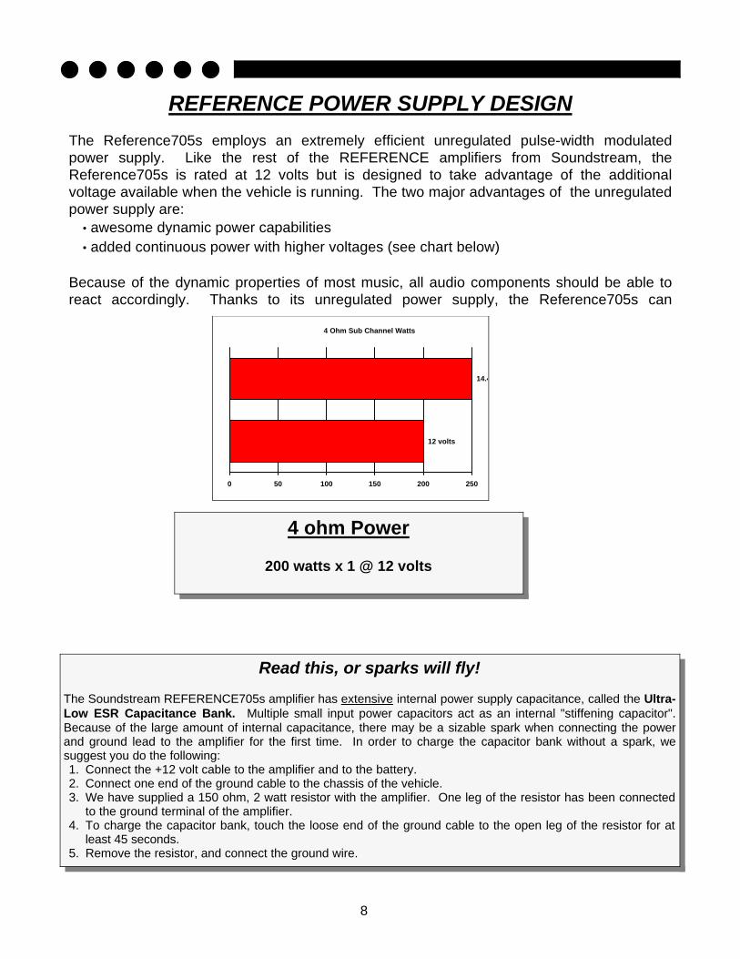
4 Ohm Sub Channel Watts
12 volts
14.4 volts
0 50 100 150 200 250
REFERENCE POWER SUPPLY DESIGN The Reference705s employs an extremely efficient unregulated pulse-width modulated power supply. Like the rest of the REFERENCE amplifiers from Soundstream, the Reference705s is rated at 12 volts but is designed to take advantage of the additional voltage available when the vehicle is running. The two major advantages of the unregulated power supply are:
• awesome dynamic power capabilities • added continuous power with higher voltages (see chart below)
Because of the dynamic properties of most music, all audio components should be able to react accordingly. Thanks to its unregulated power supply, the Reference705s can
4 ohm Power
200 watts x 1 @ 12 volts
Read this, or sparks will fly!
The Soundstream REFERENCE705s amplifier has extensive internal power supply capacitance, called the Ultra-Low ESR Capacitance Bank. Multiple small input power capacitors act as an internal "stiffening capacitor". Because of the large amount of internal capacitance, there may be a sizable spark when connecting the power and ground lead to the amplifier for the first time. In order to charge the capacitor bank without a spark, we suggest you do the following: 1. Connect the +12 volt cable to the amplifier and to the battery. 2. Connect one end of the ground cable to the chassis of the vehicle. 3. We have supplied a 150 ohm, 2 watt resistor with the amplifier. One leg of the resistor has been connected
to the ground terminal of the amplifier. 4. To charge the capacitor bank, touch the loose end of the ground cable to the open leg of the resistor for at
least 45 seconds. 5. Remove the resistor, and connect the ground wire.

9
INSTALLATION STEP 1
SETTING THE HIGH POWER/HIGH CURRENT SWITCH
(applies to subwoofer channel only)
The Reference705s’ subwoofer channel can be switched between “High Power” and “High Current” modes. This allows the Reference705s to maximize power and efficiency at impedances ≥1 Ohm in “High Power” mode, or down to 1/2 Ohm in “High Current” mode. The circuit operates by selecting a set of power supply voltage rails best suited to your particular application. One is a higher voltage “tap” optimized for high impedance applications while the other is lower voltage designed to provide more current. Unlike other amplifiers, Soundstream’s REFERENCE amplifiers can be configured to drive virtually any impedance and make maximum power!
To determine the setting for your application, follow the chart below:
4 Ω 12 Volts
2 ΩΩ 14.4 Volts
1 Ω 14.4 Volts
1/2 Ω 14.4 Volts
High Power Watts
200
300 400 n/a
High Current Watts
100 200 300 400
OTHER COMMENTS: If you blow fuses with your Reference705s, switch to the High Current mode. If the problem persists, it is likely that the amplifier is seeing a dead short, either in the speaker wire or in the speaker itself. Rectify

10
SELECTING THE CROSSOVER MODES The Reference705s incorporates a sophisticated, fully adjustable electronic crossover for each of its two pairs of channels and subwoofer channel. The Reference705s can drive a full system without need of an outboard electronic crossover. Before installing the amplifier, make certain the switches on the bottom are set to the correct positions. After setting the switches, be sure to install the hole plugs included with the amplifier.
LOW PASS The subwoofer channel is designed to operate in low pass or full range. The low pass is a continuously variable 24 dB/octave electronic crossover with a range of 30 - 120 Hz.
2-WAY
HIGH PASS The high pass crossover is used for sending only midrange and high frequency information to particular speakers. Activate the high pass crossover to drive satellite or coaxial speakers in the system along with subwoofers. You can later adjust the exact frequency from the front of the amplifier. The high pass frequency can be adjusted separately for either pair of channels of the amplifier.
REAR FILL DE-EMPHASIS The Reference705s features an innovative rear fill de-emphasis circuit which places more emphasis on the front stage when used in the five channel mode. The circuit removes frequencies above 7,000 Hz at the rate of 6 dB/octave. By removing upper frequency information from the rear fill, a more natural sounding rear fill effect is created.
3-WAY
MIDBASS/MIDRANGE BAND PASS The Reference705s can be operated in midrange or midbass “band pass” configuration. In the 3-way mode, you can tri-amplify with “active” midbass or midrange to maximize control over individual drivers. The bandpass includes a low pass and a high pass filter, which work independently of one another, to drive the midrange or midbass speakers. In 3-way crossover mode, channels 1 & 2 become HIGH PASS, and channels 3 & 4 become BANDPASS. (NOTE: In 3-way mode, channels 3 & 4 inputs are not used.)
INSTALLATION STEP 2
11
SELECTING INPUT MODES
The Reference705s can be driven with either one, two, or three pairs of stereo inputs. If your source unit has front and rear outputs, you can take advantage of its fading capability by driving the Reference705s in 5 channel mode with two pairs of inputs. When operated in the 5 channel mode with 2 pairs of inputs, the lowpass subwoofer channel will operate in a non-fading mode—it derives its signal from the front and rear inputs. After setting the input mode switches, be sure to install the hole plugs included with the amplifier. 5 CHANNEL OPERATION WITH 4 CHANNELS OF INPUT • Front input to Channels 1 & 2 and set stereo switch to either “Coherent Stereo” or “Mixed-Mono” • Rear input to Channels 3 & 4 and set input switch to “3 & 4”; stereo switch to either “Coherent
Stereo” or “Mixed-Mono” • Subwoofer input switch set to “CH 1 - 4” 5 CHANNEL OPERATION WITH 2 CHANNELS OF INPUT • Input to Channels 1 & 2; set stereo switch to either “Coherent Stereo” or “Mixed-Mono” • Channels 3 & 4: set input switch to “Internal From Ch 1 & 2”; stereo switch to either “Coherent
Stereo” or “Mixed-Mono” • Subwoofer input switch set to “CH 1 - 4” 3 CHANNEL OPERATION WITH 2 CHANNELS OF INPUT • Input to Channels 1 & 2: set stereo switch to “Mono” • Input to Channels 3 & 4: set input switch to “3 & 4”; stereo switch to “Mono” • Subwoofer input switch set to “CH 1 - 4”
INSTALLATION STEP 3
12
INSTALLATION STEP 5 WIRING
POWER AND GROUND To assure maximum output from the Reference705s, use high quality, low-loss power and ground cables. The Reference705s will accept up to 4 gauge power and ground cables, which is the only size recommended.
For system examples and
diagrams, see pages 18 - 21.
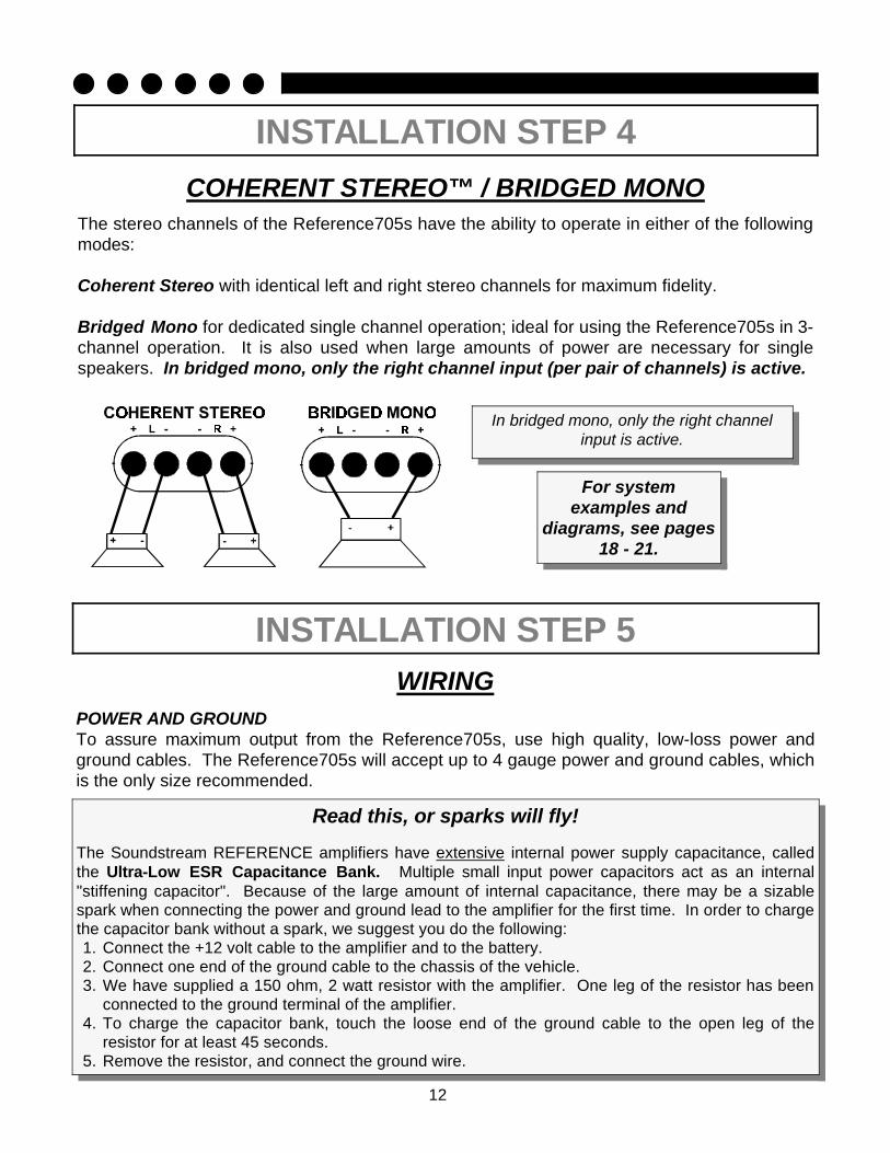
COHERENT STEREO™ / BRIDGED MONO
The stereo channels of the Reference705s have the ability to operate in either of the following modes: Coherent Stereo with identical left and right stereo channels for maximum fidelity. Bridged Mono for dedicated single channel operation; ideal for using the Reference705s in 3-channel operation. It is also used when large amounts of power are necessary for single speakers. In bridged mono, only the right channel input (per pair of channels) is active.
INSTALLATION STEP 4
In bridged mono, only the right channel input is active.
Read this, or sparks will fly!
The Soundstream REFERENCE amplifiers have extensive internal power supply capacitance, called the Ultra-Low ESR Capacitance Bank. Multiple small input power capacitors act as an internal "stiffening capacitor". Because of the large amount of internal capacitance, there may be a sizable spark when connecting the power and ground lead to the amplifier for the first time. In order to charge the capacitor bank without a spark, we suggest you do the following: 1. Connect the +12 volt cable to the amplifier and to the battery. 2. Connect one end of the ground cable to the chassis of the vehicle. 3. We have supplied a 150 ohm, 2 watt resistor with the amplifier. One leg of the resistor has been
connected to the ground terminal of the amplifier. 4. To charge the capacitor bank, touch the loose end of the ground cable to the open leg of the
resistor for at least 45 seconds. 5. Remove the resistor, and connect the ground wire.

13
WIRING DIAGRAM
WIRING (continued) CIRCUIT BREAKERS/FUSES
EXTERNAL Like all car audio amplifiers, the Reference705s must be protected with a fuse or circuit breaker located within 18” of the battery. This will prevent a fire in the event of a shorted cable. The value of the circuit breaker or fuse should be between 60 and 80 amps.
INTERNAL The Reference705s is fused on its front panel with a 40 amp Maxi-fuse. In the event of a blown power supply fuse, the “Fault” indicator on the front panel will light. Never replace the fuse with a higher value than what is supplied. This may result in amplifier damage and will void the warranty!
REMOTE TURN-ON Connect the turn-on lead from the source unit to the “Remote” input on the amplifier. When +12 volts is received, the amplifier will turn on.
SIGNAL CABLE Depending on your application, you may use one to three pairs of signal cables to drive your Reference705s. Use a high-quality cable that will be easy to install and has minimal signal loss to guarantee optimum performance.
SPEAKER CABLE The Reference705s will accept up to 8 gauge speaker cable. Use a high quality, flexible, multi-strand cable for best performance and longevity. Soundstream Speaker120 (12 gauge)

14
INSTALLATION AND MOUNTING
1. AMPLIFIER LOCATION The Reference705s employs highly efficient circuitry and Soundstream's unique ChassisinkTM design to maintain lower operating temperatures. Additional cooling may be required if the amplifier is located in an area with poor air flow, or when driving especially low impedance loads at extremely high levels.
When mounting the amplifier, it should be securely mounted to either a panel in the vehicle or an amp board or rack that is securely mounted to the vehicle. The mounting location should be either in the passenger compartment or in the trunk of the vehicle, away from moisture, stray or moving objects, and major electrical components. To provide adequate ventilation, mount the amplifier so that there are at least two inches of freely circulating air above and to the sides of it.
2. MODE SWITCHES Set High Power/High Current, Input Switches, and Crossover switches to the appropriate positions (see pages 9 - 11 and 18 - 21). These switches determine the design of the system!
3. MOUNTING THE AMPLIFIER a. Using the amplifier as a template, mark the mounting surface. b. Remove the amplifier and drill the holes. c. Mount the amplifier to the surface using the provided hardware.
4. WIRING a. Run and connect the audio signal and remote turn-on cables to the amplifier from the source
unit. b. Carefully run the positive cable from the amplifier to a fuse or circuit breaker within 18” of
the battery. c. Then connect the fuse or circuit breaker to the battery. Leave the circuit breaker off or the fuse
out until everything is bolted down. d. Secure the ground cable to a solid chassis ground on the vehicle. It may be necessary to sand
paint down to raw metal for a good connection.
e. Double check each and every connection! f. Re-connect the fuse or circuit breaker.
5. POWER UP Power up the system and look at the top of the amplifier. Depending on the subwoofer
INSTALLATION STEP 6
Your Reference705s is provided with #8 sheet metal screws which use a 1/8” drill hole.
NOTE: There may be a sizable spark when connecting the power and ground lead to the amplifier for the first time. Please see the comment on the previous page for information about connecting power and ground wires to your amplifier. Please see the comment on page 12.
15
INSTALLATION STEP 7
LEVEL SETTING The input levels are adjusted by means of the input level controls located on the front of the amplifier. This is a unique dual-stage circuit that adjusts both level and gain. This topology maintains better Signal to Noise ratios even with low output sources. In the ideal situation, all components in the audio system reach maximum undistorted output at the same time. The reason is because an amplifier will only make what comes into it bigger. So, if you send it a distorted signal from the head unit, it is going to amplify distorted information. The same thing holds true if an outboard processor or crossover begins to distort before you have maximum output from the amplifier. By setting all components to reach clipping at the same time, you can maximize the output of your system. For the Reference705s, follow the below procedure for the quickest, easiest means of setting the levels.
1. Turn the amplifier's input levels to minimum position (fully counter-clockwise).
2. Set source unit volume to approximately 3/4 of full volume. 3. While playing dynamic source material, slowly increase the amplifier’s input level until a
near maximum undistorted level is heard in the system.
NOTE: Your best combination of output and Signal to Noise ratio will be achieved when the input levels are set between 500 mV and 5.0 V.
16
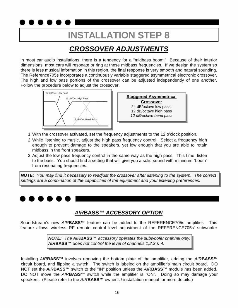
CROSSOVER ADJUSTMENTS In most car audio installations, there is a tendency for a “midbass boom.” Because of their interior dimensions, most cars will resonate or ring at these midbass frequencies. If we design the system so there is less musical information in this region, the final response is very smooth and natural sounding. The Reference705s incorporates a continuously variable staggered asymmetrical electronic crossover. The high and low pass portions of the crossover can be adjusted independently of one another. Follow the procedure below to adjust the crossover.
Staggered Asymmetrical Crossover
24 dB/octave low pass, 12 dB/octave high pass 12 dB/octave band pass
NOTE: You may find it necessary to readjust the crossover after listening to the system. The correct settings are a combination of the capabilities of the equipment and your listening preferences.
INSTALLATION STEP 8
1.With the crossover activated, set the frequency adjustments to the 12 o’clock position. 2.While listening to music, adjust the high pass frequency control. Select a frequency high
enough to prevent damage to the speakers, yet low enough that you are able to retain midbass in the front speakers.
3.Adjust the low pass frequency control in the same way as the high pass. This time, listen to the bass. You should find a setting that will give you a solid sound with minimum “boom” from resonating frequencies.
24 dB/Oct. Low Pass
12 dB/Oct. High Pass
12 dB/Oct. Band Pass
AIRBASS™ ACCESSORY OPTION Soundstream's new AIRBASS™ feature can be added to the REFERENCE705s amplifier. This feature allows wireless RF remote control level adjustment of the REFERENCE705s' subwoofer
NOTE: The AIRBASS™ accessory operates the subwoofer channel only. AIRBASS™ does not control the level of channels 1,2,3 & 4.
Installing AIRBASS™ involves removing the bottom plate of the amplifier, adding the AIRBASS™ circuit board, and flipping a switch. The switch is labeled on the amplifier's main circuit board. DO NOT set the AIRBASS™ switch to the "IN" position unless the AIRBASS™ module has been added. DO NOT move the AIRBASS™ switch while the amplifier is "ON". Doing so may damage your speakers. (Please refer to the AIRBASS™ owner's / installation manual for more details.)

17
INSTALLATION STEP 9
LSE.Q THEORY AND USE
LSE.Q is a proprietary subwoofer control circuit included with the Reference705s amplifier. It is capable of both removing subsonic energy in program material and providing a variable boost at low frequencies. The circuit consists of two controls. One adjusts the frequency of operation, and the other adjusts the range of boost. With both controls adjusted fully counter-clockwise, no boost is applied and the amplifier is flat in response down to 20 Hz.
The frequency control (Hz) adjusts the starting point of the subsonic filter. This high pass filter can be adjusted from 20 Hz up to a maximum of 60 Hz. This control is useful for setting the lowest frequency that your subwoofer will see. (See figure 1)
The Q control adjusts the amount of boost applied at the set frequency. This is adjustable from .707 (flat) to 2.8 (+9 dB). (See figure 2)
When the Q is set to .707 (Butterworth), LSE.Q acts as a sub-sonic filter only. (See figure 3)
The simple act of removing the signal below the vented tuning frequency can improve system output by as much as 3 dB. With Q values greater than .707, boost is added in addition to the sub-sonic filter. (see figure 4)
Application
Woofers in vented enclosures have good power handling characteristics above the tuning frequency, but below the tuning frequency, power handling drops off considerably. This is due to the loss of any appreciable resistive air mass. At frequencies below resonance, the
woofer starts to behave as if it were mounted in “free-air”. If we wish to improve the performance of a vented system, we should remove these unwanted signals from our system. These can be removed by adding the subsonic filter. Figure 5 shows the effectiveness of LSE.Q on woofer excursion. Woofer travel is 7.5 mm at 10 Hz, with LSE.Q properly adjusted, this excursion can be reduced to less than 1 mm. This is of great benefit to lowering woofer distortion and increasing output.
Adjustment An easy method of optimizing your existing subwoofer enclosure with LSE.Q's “Hz” control is as follows.
1. Adjust frequency and boost control to full CCW position.
2. While listening to music with strong bass content at a moderate level, slowly adjust frequency control clockwise. Listen for a reduction of bass response. Now, rotate frequency control slightly backwards. This serves the purpose of removing the “subsonic” bass energy.
Soundstream’s LSE.Q contains the same type of circuit with the added benefit of infinite adjustability. Our “Q” and “Hz” control can provide virtually any combination of boost and cut to suit your designs. So, LSE.Q can
dB
Frequency (Hz)
-20
-3010
-25
-15
-10
5
0
-5
10
50 100 200
FIG. 2 Variable “Q”
Q=2.8
Q=0.707
dB
Frequency (Hz)
-20
-3010
-25
-15
-10
5
0
-5
10
50 100 200
FIG. 4 Variable “Q”
FIG. 1 LSE.Q
-10
Frequency (Hz)10-30
-25
-15
-20
-5dB
0
5
10
50 100 200
FIG. 3 Variable High Pass
FIG. 5 Limited Excursion
10 Frequency (Hz) 50 100 200
Xd(mM)
8.0
7.0
6.0
5.0
4.0
3.0
2.0
1.0
0.0

18
SAMPLE SYSTEM #1 2-way front to rear fade with constant bass
4 channels of input 4 channels of 2-way high pass, sub channel in low pass
19
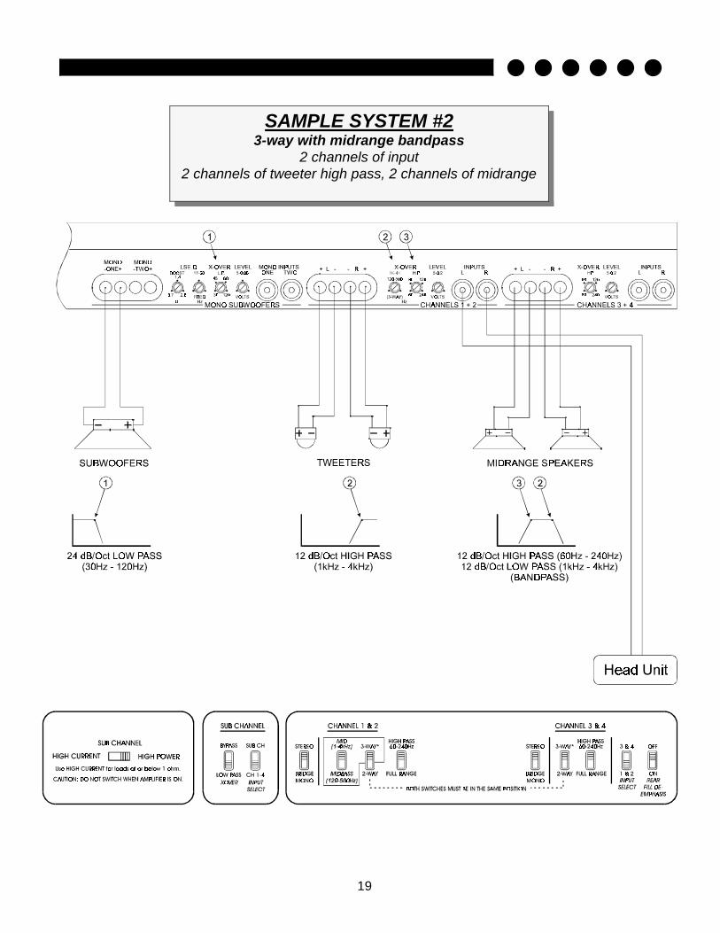
SAMPLE SYSTEM #2 3-way with midrange bandpass
2 channels of input 2 channels of tweeter high pass, 2 channels of midrange
20
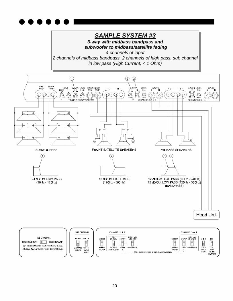
SAMPLE SYSTEM #3 3-way with midbass bandpass and
subwoofer to midbass/satellite fading 4 channels of input
2 channels of midbass bandpass, 2 channels of high pass, sub channel in low pass (High Current; < 1 Ohm)
21
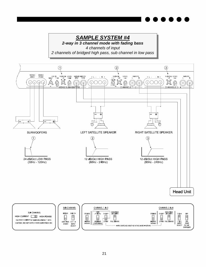
SAMPLE SYSTEM #4 2-way in 3 channel mode with fading bass
4 channels of input 2 channels of bridged high pass, sub channel in low pass

22
PROTECTION CIRCUITRY Your Reference705s is protected against both overheating and short circuits by means of the following circuits: • Main power supply fuses (Maxi-fuse at 40 amps) • Smart Power Supply Thermal Rollback activating at 85°C. • A fail-safe thermal protection circuit activating at 95°C. • Self-resetting circuit breakers on channels 1,2,3 & 4 to protect against short circuits. Your amplifier also incorporates an innovative Fault Diagnosis system that identifies a blown power supply fuse. NOTE: If you experience blown main power supply fuse, DO NOT increase value beyond the 40 amp maxi-fuse! Doing so will void your warranty and may damage your amplifier.
TROUBLESHOOTING
PROBLEM CAUSE
No sound and LED's are not lit • no power or ground at amp • no remote turn-on signal • blown fuse near battery
Fault LED is lit • amp power supply fuse is blown or missing
Repeatedly blown amp fuse, frequent activa-tion of Smart Power Supply Circuit
• check speaker configuration, amp may be in “High Power” mode, put amp into “High Current” mode if subwoofer load is less than 1 ohm (see p.8, “Setting High Power/High Current Switch”)
• speaker or leads may be shorted • verify adequate amplifier ventilation
no sound from channels 3 & 4 with 2 chan-nels of input
• check input settings on bottom of amplifier—switch should be set to inputs “1 & 2”
Channel 1, 2, 3 or 4 experience intermittent output
• circuit breakers on these channels are activat-ing. Check for a possible short in the speaker wire or in the speaker itself
• Verify the impedance of the load is at or above the rated minimum impedance for these chan-nels

23
SPECIFICATIONS
POWER OUTPUT
CROSSOVER SPECIFICATIONS (all continuously variable): 2-way
High Pass: 12 dB/octave, 60 - 240 Hz Low Pass: 24 dB/octave, 30 - 120 Hz
3-way Tweeter High Pass/Midrange Low Pass: 12 dB/octave, 1 K - 4 KHz Midrange or Midbass High Pass: 12 dB/octave, 60 - 240 Hz Mid High Pass/Midbass Low Pass: 12 dB/octave, 240 - 960 Hz
Subwoofer Low Pass: 24 dB/octave, 30 - 120 Hz DIMENSIONS: 19.0” W x 9.8” D x 2.25” H
SERVICE The Reference705s is protected by a limited warranty. Please read the enclosed warranty card.
THD < 0.1%
Signal to Noise > 100 dB
Frequency Response 20 Hz to 20 kHz +/- 0.5 dB
Bandwidth 15 Hz to 50 kHz
Stereo Separation > 90 dB
Damping > 200
Input Sensitivity 100 mV - 2.5 V
Input Impedance 12 k ohms
4 Ω Stereo (8 Ω Bridged)
12 Volts
2 ΩΩ Stereo (4 Ω(4 Ω
Bridged)
Watts 50 w x 4 (100 w x 2)
100 w x 4 (200 w x 2)
SATELLITE CHANNELS SUBWOOFER CHANNEL
4 Ω 12
Volts
2 ΩΩ 14.4 Volts
1 Ω 14.4 Volts
1/2 Ω 14.4 Volts
High 200 w 300 w 400 w n/a
High Cur- 100 w 200 w 300 w 400 w

24
SOUNDSTREAM TECHNOLOGIES 120 Blue Ravine Road Folsom Ca lifornia 95630
USA