reference and equivalent methods used to measure national
TRANSCRIPT

Reference and Equivalent Methods Used to Measure National Ambient Air Quality Standards (NAAQS) Criteria Air Pollutants - Volume I
Authors: Joseph H. Gilliam (EPA/ORD) and Eric S. Hall (EPA/ORD)
PRESORTED STANDARDPOSTAGE & FEES PAID
EPAPERMIT NO.G-35
Office of Research and Development (8101R)Washington, DC 20460
Official BusinessPenalty for Private Use$300
Recycled/Recyclable Printed on paper that contains a minimum of 50% post-consumer fiber content processed chlorine free
EPA/600/R-16/139 | June 2016 | www.epa.gov
Office of Research and DevelopmentNational Exposure Research Laboratory


Reference and Equivalent Methods Used to Measure National Ambient Air Quality Standards (NAAQS) Criteria Air Pollutants - Volume I Authors: Joseph H. Gilliam (EPA/ORD) and Eric S. Hall (EPA/ORD)
EPA/600/R-16/139 | June 2016 | www.epa.gov
Office of Research and DevelopmentNational Exposure Research Laboratory


iii
Executive Summary
There are a number of Federal Reference Method (FRM) and Federal Equivalent Method (FEM) systems used to monitor the six criteria air pollutants (Lead [Pb], Carbon Monoxide [CO], Sulfur Dioxide [SO2], Nitrogen Dioxide [NO2], Ozone [O3], Particulate Matter [PM]) to determine if an area is compliant with the National Ambient Air Quality Standards (NAAQS) for these air pollutants. EPA publishes the list of active FRMs and FEMs on a semi-annual basis, but the list is not a comprehensive one, and anyone wishing to find information for all of the FRMs and FEMs must consult a large number of resources, since the information is not located in a single document. This report is the first attempt to list all of the available FRMs and FEMs in a single document.
As new FRMs and FEMs are approved, they will be listed in subsequent volumes of this document. This document is a resource for researchers needing to understand the operation of the monitors/samplers/analyzers used for criteria air pollutants that may be the focus of health studies. It is also a resource for regulatory personnel who need to know which air pollution monitoring systems are available (e.g., active and valid) for use in measurement and calibration studies. The document is a planning tool for scientists who validate and approve new air pollution monitoring systems, allowing them to assess which systems need to be upgraded during the NAAQS reviews for each criteria air pollutant.

v
Table of Contents
1.0 Federal Reference Methods (FRM) and Federal Equivalent Methods (FEMs):Particulate Matter (PM10). .. . .. . .. . .. . .. . .. 1Federal Reference Method (FRM): In-Stack Particulate Filtration (CFR 40, Part 50, App. J).. . .. . .. . .. . .. . .. . .. . .. . .. . .. 1Federal Equivalent Method (FEM): Beta-Attenuation Monitoring. .. . .. . .. . .. . .. . .. . .. . .. . .. . .. . .. . .. . .. . .. . .. . .. . .. . .. 7Federal Equivalent Method (FEM): Tapered Element Oscillating Microbalance (TEOM®). .. . .. . .. . .. . .. . .. . .. . .. . .. . .10Federal Equivalent Method (FEM): Dichotomous Air Sampler .. . .. . .. . .. . .. . .. . .. . .. . .. . .. . .. . .. . .. . .. . .. . .. . .. . .. . .12
2.0 Federal Reference Methods (FRM) and Federal Equivalent Methods (FEMs):Particulate Matter (PM2.5) .. . .. . .. . .. . .. . .13Federal Reference Method (FRM): In-stack Particulate Filtration (CFR 40, Part 50, App. L).. . .. . .. . .. . .. . .. . .. . .. . .. . .13Federal Equivalent Method (FEM): Beta-Attenuation Monitoring. .. . .. . .. . .. . .. . .. . .. . .. . .. . .. . .. . .. . .. . .. . .. . .. . .. . .17Federal Equivalent Method (FEM): Very Sharp Cut Cyclone (VSCC) .. . .. . .. . .. . .. . .. . .. . .. . .. . .. . .. . .. . .. . .. . .. . .. . .20Federal Equivalent Method (FEM): Tapered Element Oscillating Microbalance (TEOM®). .. . .. . .. . .. . .. . .. . .. . .. . .. . .24Federal Equivalent Method (FEM): Dichotomous Air Sampler .. . .. . .. . .. . .. . .. . .. . .. . .. . .. . .. . .. . .. . .. . .. . .. . .. . .. . .26Federal Equivalent Method (FEM): Laser Aerosol Spectrometry . .. . .. . .. . .. . .. . .. . .. . .. . .. . .. . .. . .. . .. . .. . .. . .. . .. . .28Federal Reference Method (FRM): In-Stack Particulate Filtration (CFR 40, Part 50, App. L) . . .. . .. . .. . .. . .. . .. . .. . .. . .29
3.0 Federal Reference Methods (FRM) and Federal Equivalent Methods (FEMs): Particulate Matter – Coarse: (PM10-2.5) or (PMc) .. . .. . .. . .. . .. . .. . .. . .. . .. . .. . .. . .. . .. . .. . .. . .. . .. . .. . .. . .. . .. . .. . .. . .29Federal Equivalent Method (FEM): Beta-Attenuation Monitoring. .. . .. . .. . .. . .. . .. . .. . .. . .. . .. . .. . .. . .. . .. . .. . .. . .. . .31Federal Equivalent Method (FEM): Tapered Element Oscillating Microbalance (TEOM®). .. . .. . .. . .. . .. . .. . .. . .. . .. . .32Federal Equivalent Method (FEM): Dichotomous Air Sampler .. . .. . .. . .. . .. . .. . .. . .. . .. . .. . .. . .. . .. . .. . .. . .. . .. . .. . .33
4.0 Federal Reference Methods (FRM) and Federal Equivalent Methods (FEMs):Sulfur Dioxide (SO2). . .. . .. . .. . .. . .. . .. . .35Federal Reference Method (FRM): Pararosaniline Method (CFR 40, Part 50, App. A).. . .. . .. . .. . .. . .. . .. . .. . .. . .. . .. . .35Federal Equivalent Method (FEM): U.V. Fluorescence . . .. . .. . .. . .. . .. . .. . .. . .. . .. . .. . .. . .. . .. . .. . .. . .. . .. . .. . .. . .. . .35
5.0 Federal Reference Methods (FRM) and Federal Equivalent Methods (FEMs):Ozone (O3) . . .. . .. . .. . .. . .. . .. . .. . .. . .. . .43Federal Reference Method (FRM): Ethylene Chemiluminescence (CFR 40, Part 50, App. D) . .. . .. . .. . .. . .. . .. . .. . .. . .43Federal Equivalent Method (FEM): U.V. Photometry .. . .. . .. . .. . .. . .. . .. . .. . .. . .. . .. . .. . .. . .. . .. . .. . .. . .. . .. . .. . .. . .45Federal Equivalent Method (FEM): Differential Optical Absorption Spectroscopy (DOAS) .. . .. . .. . .. . .. . .. . .. . .. . .. . .54
6.0 Federal Reference Methods (FRM) and Federal Equivalent Methods (FEMs):Carbon Monoxide (CO) . . .. . .. . .. . .. . .. . .57Federal Reference Method (FRM): Non-Dispersive Infrared Photometry (CFR 40, Part 50, App. C) . .. . .. . .. . .. . .. . .. . .57Federal Equivalent Method (FEM): U.V. Photometry .. . .. . .. . .. . .. . .. . .. . .. . .. . .. . .. . .. . .. . .. . .. . .. . .. . .. . .. . .. . .. . .64Federal Reference Method (FRM): Gas Phase Chemiluminescence (CFR 40, Part. 50, App. F) .. . .. . .. . .. . .. . .. . .. . .. . .65
7.0 Federal Reference Methods (FRM) and Federal Equivalent Methods (FEMs):Nitrogen Dioxide (NO2) – a component of Oxides of Nitrogen (NOx).. . .. . .. . .. . .. . .. . .. . .. . .. . .. . .. . .. . .. . .. . .. . .. . .. . .. . .. . .. . .. . .. . .. . .. . .. . .. . .. . .. . .. . .. . .65Federal Equivalence Method (FEM): Sodium Arsenite (SA) Method for NO2 . .. . .. . .. . .. . .. . .. . .. . .. . .. . .. . .. . .. . .. . .73Federal Equivalence Method (FEM): TGS-ANSA .. . .. . .. . .. . .. . .. . .. . .. . .. . .. . .. . .. . .. . .. . .. . .. . .. . .. . .. . .. . .. . .. . .73Federal Equivalence Method (FEM): Differential Optical Absorption Spectrometry (DOAS) . . .. . .. . .. . .. . .. . .. . .. . .. . .73Federal Equivalent Method (FEM): U.V. Photolytic Conversion . . .. . .. . .. . .. . .. . .. . .. . .. . .. . .. . .. . .. . .. . .. . .. . .. . .. . .75Federal Equivalent Method (FEM): Cavity Attenuated Phase Shift Spectroscopy (CAPS) . . .. . .. . .. . .. . .. . .. . .. . .. . .. . .76
8.0 Federal Reference Methods (FRM) and Federal Equivalent Methods (FEMs):Lead (Pb) .. . .. . .. . .. . .. . .. . .. . .. . .. . .. . .77Federal Reference Method (FRM): Reference Method for the Determination of Lead (Pb) in Total Suspended Particulate (TSP) Matter {Collected from Ambient Air Using a High-Volume Sampler} (CFR 40, Part 50, Appendix G) . .. . .. . .. . .77Federal Equivalent Method (FEM): X-Ray Fluorescence Spectrometry . .. . .. . .. . .. . .. . .. . .. . .. . .. . .. . .. . .. . .. . .. . .. . .77Federal Reference Method (FRM): Flame/Flameless Atomic Absorption Spectroscopy . .. . .. . .. . .. . .. . .. . .. . .. . .. . .. . .78Federal Reference Method (FRM): Inductively Coupled Plasma-Optical Emission Spectrometry . .. . .. . .. . .. . .. . .. . .. . .78Federal Reference Method (FRM): Inductively Coupled Plasma-Mass Spectrometry (ICP-MS).. . .. . .. . .. . .. . .. . .. . .. . .80
9.0 References EPA Reference and Equivalent Methods . . .. . .. . .. . .. . .. . .. . .. . .. . .. . .. . .. . .. . .. . .. . .. . .. . .. . .. . .. . .. . .. . .83Appendix A Information Requests for FRMs and FEMs.. . .. . .. . .. . .. . .. . .. . .. . .. . .. . .. . .. . .. . .. . .. . .. . .. . .. . .. . .. . .. . .. .A-1

vi
List of Figures
Figure 1 Andersen Model RAAS10-100 PM10 Single Channel PM10 Sampler (RFPS-0699-130) . . . . . . . . . . . . . . .1
Figure 2 Andersen Model RAAS10-200 PM10 Single Channel PM10 Audit Sampler (RFPS-0699-131) . . . . . . . . . . . .2
Figure 3 Andersen Model RAAS10-300 PM10 Multi Channel PM10 Sampler (RFPS-0699-132). . . . . . . . . . . . . . . .2
Figure 4 BGI Incorporated Model PQ100 Air Sampler (RFPS-1298-124) . . . . . . . . . . . . . . . . . . . . . . . . . . .2
Figure 5 BGI Incorporated Model PQ200 Air Sampler (RFPS-1298-125) . . . . . . . . . . . . . . . . . . . . . . . . . . .3
Figure 6 Ecotech Model 3000 PM10 High Volume Air Sampler (RFPS-0706-162) . . . . . . . . . . . . . . . . . . . . . . .3
Figure 7 Graseby Andersen/GMW Model 1200 High-Volume Air Sampler (RFPS-1287-063) . . . . . . . . . . . . . . . .3
Figure 8 Graseby Andersen/GMW Model 321-B High-Volume Air Sampler (RFPS-1287-064) . . . . . . . . . . . . . . . .4
Figure 9 Thermo Scientific or Rupprecht & Patashnick Partisol® Model 2000 Air Sampler (RFPS-0694-098) . . . . . . . .5
Figure 10 Thermo Scientific Partisol® 2000-FRM PM10 Air Sampler or Thermo Fisher Scientific Partisol® 2000i PM10 Air Sampler or Rupprecht and Patashnick Partisol®-FRM 2000 PM10 Air Sampler (RFPS-1298-126) . . . .5
Figure 11 Thermo Scientific Partisol®-Plus 2025 PM10 Sequential Air Sampler or Thermo Fisher Scientific Partisol® 2025i PM10 Sequential Air Sampler or Rupprecht and Patashnick Partisol®-Plus 2025 PM10 Sequential Air Sampler (RFPS-1298-127) . . . . . . . . . . . . . . . . . . . . . . . . . . . . . . . . . . . . . . . . . . . .5
Figure 12. Tisch Environmental Model TE-6070 PM10 High-Volume Air Sampler or New Star Environmental Model NS-6070 PM10 High-Volume Air Sampler (RFPS-0202-141) . . . . . . . . . . . . . . . . . . . . . . . . . . . . . . . . . .6
Figure 13 Tisch Environmental Model TE-Wilbur10 Particulate Sampler – PM10 (RFPS-0714-216) . . . . . . . . . . . . . .6
Figure 14 DKK-TOA Models FPM-222/222C, FPM223/223C, and DUB-222(S)/223(S) PM10 Monitor (EQPM-0905-156) . . . . . . . . . . . . . . . . . . . . . . . . . . . . . . . . . . . . . . . . . . . . . . . . . . .7
Figure 16 Met One or Sibata Models BAM/GBAM 1020, BAM/GBAM 1020-1, Horiba APDA-371, or Ecotech Spirant BAM1000 (EQPM-0798-122) . . . . . . . . . . . . . . . . . . . . . . . . . . . . . . . . . . . . . . . . . . . . .8
Figure 15 Environnement S.A. Model MP101M PM10 Monitor (EQPM-0404-151). . . . . . . . . . . . . . . . . . . . . . .8
Figure 17 Opsis Model SM200 PM10 Monitor (EQPM-0810-193) . . . . . . . . . . . . . . . . . . . . . . . . . . . . . . . .9
Figure 18 Teledyne Model 602 BetaPLUS Particle Measurement System or SWAM 5a Dual Channel Monitor (EQPM-0912-205) . . . . . . . . . . . . . . . . . . . . . . . . . . . . . . . . . . . . . . . . . . . . . . . . . . .9
Figure 19 Thermo Andersen Series FH 62 C14 Continuous PM10 Monitor Thermo Scientific Model 5014i Beta (5014i Beta), Continuous Ambient Particulate Monitor (EQPM-1102-150) . . . . . . . . . . . . . . . . . . . . .9
Figure 20. Thermo Scientific TEOM® 1400AB/TEOM® 1405 Ambient Particulate Monitor or Rupprecht & Patashnick TEOM® Series 1400/1400a PM10 Monitors (EQPM-1090-079) . . . . . . . . . . . . . . . . . . . . . . . . . . 10
Figure 21 Thermo Scientific TEOM® 1405-DF Dichotomous Ambient Particulate Monitor with FDMS® (EQPM-1013-208) . . . . . . . . . . . . . . . . . . . . . . . . . . . . . . . . . . . . . . . . . . . . . . . . . . 11
Figure 22 Thermo Scientific Partisol® 2000-D Dichotomous Air Sampler or Thermo Fisher Scientific Partisol® 2000i-D Dichotomous Air Sampler (EQPS-0311-197) . . . . . . . . . . . . . . . . . . . . . . . . . . . . . . . . . . . . 12
Figure 23 Thermo Scientific Dichotomous Partisol®-Plus 2025-D Sequential Air Sampler or Thermo Fisher Scientific Dichotomous Partisol® 2025i-D Sequential Air Sampler (EQPS-0311-198) . . . . . . . . . . . . . . . . . . . . 12
Figure 24 Andersen Model RAAS2.5-200 PM2.5 Ambient Audit Air Sampler (RFPS-0299-128) . . . . . . . . . . . . . . . 13
Figure 25 BGI Inc. Models PQ200 or PQ200A PM2.5 Ambient Fine Particle Sampler (RFPS-0498-116) . . . . . . . . . . . 14
Figure 26 Graseby Andersen Model RAAS2.5-100 PM2.5 Ambient Air Sampler (RFPS-0598-119) . . . . . . . . . . . . . . 14
vii
Figure 27 Graseby Andersen Model RAAS2.5-300 PM2.5 Sequential Ambient Air Sampler (RFPS-0598-120) . . . . . . . . 14
Figure 28 Met One e-FRM– PM2.5 (RFPS-0315-221) . . . . . . . . . . . . . . . . . . . . . . . . . . . . . . . . . . . . . 15
Figure 29 Rupprecht & Patashnick Partisol®-FRM Model 2000 PM2.5 Air Sampler (RFPS-0498-117) . . . . . . . . . . . 15
Figure 30 Rupprecht & Patashnick Partisol® Model 2000 PM2.5 Audit Sampler (RFPS-0499-129) . . . . . . . . . . . . . . 15
Figure 31 Rupprecht & Patashnick Partisol®-Plus Model 2025 Sequential Air Sampler (RFPS-0498-118) . . . . . . . . . 16
Figure 32 Tisch Environmental Model TE-Wilbur2.5 Particulate Sampler – PM2.5 (RFPS-1014-219) . . . . . . . . . . . . 16
Figure 33 Environnement S.A. Model MP101M PM2.5 Monitor (EQPM-1013-211) . . . . . . . . . . . . . . . . . . . . . 17
Figure 34 Met One BAM-1020 Monitor – PM2.5 FEM Configuration, Horiba APDA-371– PM2.5 Configuration, or Ecotech Spirant BAM1100 (EQPM-0308-170) . . . . . . . . . . . . . . . . . . . . . . . . . . . . . . . . . . . . . . . . 18
Figure 35 Met One BAM-1022 Real Time Beta Attenuation Mass Monitor-Outdoor PM2.5 FEM Configuration (EQPM-1013-209) . . . . . . . . . . . . . . . . . . . . . . . . . . . . . . . . . . . . . . . . . . . . . . . . . . 18
Figure 36 Teledyne Model 602 BetaPLUS Particle Measurement System or SWAM 5a Dual Channel Monitor (EQPM-0912-204) . . . . . . . . . . . . . . . . . . . . . . . . . . . . . . . . . . . . . . . . . . . . . . . . . . 19
Figure 37 Thermo Scientific Model 5014i or Thermo Scientific FH62C14-DHS Continuous Ambient Particle Monitor (EQPM-0609-183) . . . . . . . . . . . . . . . . . . . . . . . . . . . . . . . . . . . . . . . . . . . . . . . . . . 19
Figure 38. Thermo Scientific Model 5030i SHARP Monitor or Model 5030 SHARP Monitor (EQPM-0609-184) . . . . . . 19
Figure 39 BGI Inc. Models PQ200-VSCC™ or PQ200A-VSCC™ PM2.5 Sampler (RFPS-0498-116 or EQPM-0202-142) . 20
Figure 40 Opsis SM200- Dust Monitor (EQPM-0812-203) . . . . . . . . . . . . . . . . . . . . . . . . . . . . . . . . . . 21
Figure 41 Thermo Scientific Partisol® 2000-FRM PM2.5 Air Sampler or Thermo Fisher Scientific Partisol® 2000i PM2.5 Air Sampler or Rupprecht & Patashnick Partisol®-FRM 2000 PM2.5 Air Sampler (RFPS-0498-117 or EQPM-0202-143) . . . . . . . . . . . . . . . . . . . . . . . . . . . . . . . . . . . . . . . 22
Figure 42 Thermo Scientific Partisol®-Plus 2025 Sequential PM2.5 Air Sampler or Thermo Fisher Scientific Partisol® 2025i Sequential PM2.5 Air Sampler or Rupprecht & Patashnick Partisol®-Plus 2025 PM2.5 Sequential Sampler (RFPS-0498-118 or EQPM-0202-145) . . . . . . . . . . . . . . . . . . . . . . . . . . . . . . . . . . . . . . . 22
Figure 43 Tisch Environmental Model TE-Wilbur2.5 Particulate Sampler – PM2.5 (EQPS-0415-223) . . . . . . . . . . . . 23
Figure 44 Thermo Scientific TEOM® 1400a Ambient Particulate Monitor with Series 8500C FDMS®; Thermo Scientific TEOM® 1405-F Ambient Particulate Monitor with FDMS® (EQPM-0609-181) . . . . . . . . . . . . . . . . . 24
Figure 45 Thermo Scientific TEOM® 1405-DF Dichotomous Ambient Particulate Monitor with FDMS® (EQPM-0609-182) . . . . . . . . . . . . . . . . . . . . . . . . . . . . . . . . . . . . . . . . . . . . . . . . . . 25
Figure 46 Thermo Scientific Partisol® 2000-D Dichotomous Air Sampler or Thermo Fisher Scientific Partisol® 2000i-D Dichotomous Air Sampler (EQPS-0509-177) . . . . . . . . . . . . . . . . . . . . . . . . . . . . . . . . . . . . 26
Figure 47 Thermo Scientific Partisol®-Plus 2025-D Dichotomous Sequential Air Sampler or Thermo Fisher Scientific Partisol® 2025i-D Dichotomous Sequential Air Sampler (EQPS-0509-179) . . . . . . . . . . . . . . . . . . . . 27
Figure 48 Grimm Model EDM 180 PM2.5 Monitor (EQPM-0311-195) . . . . . . . . . . . . . . . . . . . . . . . . . . . . 28
Figure 49 BGI Incorporated Model PQ200 Sampler Pair (RFPS-1208-173) . . . . . . . . . . . . . . . . . . . . . . . . . 29
Figure 50 Thermo Scientific Partisol®-Plus 2025 Sequential PM10-2.5 Air Sampler Pair or Thermo Fisher Scientific Partisol® 2025i Sequential PM10-2.5 Air Sampler Pair (RFPS-0509-176) . . . . . . . . . . . . . . . . . . . . . . . . . . . 30
Figure 51 Tisch Environmental Model TE-Wilbur Low-Volume Air Particulate Sampler Pair (RFPS-1014-220) . . . . . . 30
Figure 52 Teledyne Model 602 BetaPLUS Particle Measurement System or SWAM 5a Dual Channel Monitor (EQPM -0912-206) . . . . . . . . . . . . . . . . . . . . . . . . . . . . . . . . . . . . . . . . . . . . . . . . . . . . . . . . . 31
Figure 53 Thermo Scientific TEOM® 1405-DF Dichotomous Ambient Particulate Monitor with FDMS® (EQPM-1013-207) . . . . . . . . . . . . . . . . . . . . . . . . . . . . . . . . . . . . . . . . . . . . . . . . . 32
Figure 54 Met One Instruments BAM-1020 PM10-2.5 Measurement System (EQPM-0709-185) . . . . . . . . . . . . . . . 33
viii
Figure 55 Thermo Scientific Partisol® 2000-D Dichotomous Air Sampler or Thermo Fisher Scientific Partisol® 2000i-D Dichotomous Air Sampler (EQPS-0509-178) . . . . . . . . . . . . . . . . . . . . . . . . . . . . . . . . . . . . 34
Figure 56 Thermo Scientific Partisol®-Plus 2025-D Dichotomous Sequential Air Sampler or Thermo Fisher Scientific Partisol® 2025iD Dichotomous Sequential Air Sampler (EQPS-0509-180) . . . . . . . . . . . . . . . 34
Figure 57 Dasibi Model 4108 U.V. Fluorescence SO2 Analyzer (EQSA-1086-061) . . . . . . . . . . . . . . . . . . . . . . 36
Figure 58 DKK-TOA Corp. Model GFS-312E Ambient SO2 Analyzer (EQSA-1107-168) . . . . . . . . . . . . . . . . . . 36
Figure 59. Ecotech Serinus 50 Sulfur Dioxide Analyzer or Opsis AB OPS50 Sulfur Dioxide Analyzer or Teledyne Analytical Instruments 6400E Sulfur Dioxide Analyzer or Tisch Environmental TE 2.0 Sulfur Dioxide Analyzer (EQSA-0809-188) . . . . . . . . . . . . . . . . . . . . . . . . . . . . . . . . . . . . . 37
Figure 60. Environnement S.A. Model AF21M SO2 Analyzer (EQSA-0292-084) . . . . . . . . . . . . . . . . . . . . . . . 37
Figure 61. Environnement S.A. Model AF22M SO2 Analyzer (EQSA-0802-149) . . . . . . . . . . . . . . . . . . . . . . . 37
Figure 63 Horiba Model APSA-370 Ambient SO2 Monitor (EQSA-0506-159) . . . . . . . . . . . . . . . . . . . . . . . . 38
Figure 62 Horiba Models APSA-360, APSA-360-CE, or APSA-360A-CE SO2 Monitors (EQSA-0197-114) . . . . . . . . 38
Figure 64 SERES Model SF 2000 G Sulfur Dioxide Analyzer (EQSA-0810-194) . . . . . . . . . . . . . . . . . . . . . . 39
Figure 65 SIR S.A. Model S-5001 U.V. Fluorescence SO2 Analyzer (EQSA-0507-166) . . . . . . . . . . . . . . . . . . . 39
Figure 66 Teledyne Advanced Pollution Instrumentation, Models 100A, 100AS, 100E, 100EU, T100, T100U; Teledyne Analytical Instruments Model 6400A; or Teledyne Monitor Labs sensor-e™ Model TML-50 SO2 Analyzers; or recordum airpointer® system module 801-001000 (EQSA-0495-100) . . . . . . . . . . . . . 40
Figure 67 Teledyne Monitor Labs/Casella/Ecotech Model ML9850/CM2050/EC9850/EC9850T; Teledyne Monitor Labs/Casella/ Ecotech/Model ML9850B/CM2050B/EC9850B; or Wedding & Associates Model 1040 SO2 Analyzers (EQSA-0193-092) . . . . . . . . . . . . . . . . . . . . . . . . . . . . . . . . . . . . . . . . . . . . . . . . . . 41
Figure 68 Thermo Electron Model 43 SO2 Analyzer (EQSA-0276-009) . . . . . . . . . . . . . . . . . . . . . . . . . . . . 41
Figure 69 Thermo Environmental Instruments, Inc./Thermo Electron Models 43A, 43B, 43C, 43C-TLE, 43i, 43i-TLE SO2 Analyzers (EQSA-0486-060) . . . . . . . . . . . . . . . . . . . . . . . . . . . . . . . . . . . . . 42
Figure 72 2B Technologies Model 106-L or 106-OEM-L Ozone Monitor (EQOA-0914-218) . . . . . . . . . . . . . . . . 46
Figure 73 Dasibi Models 1003-AH, 1003-PC, or 1003-RS Ozone Analyzers (EQOA-0577-019). . . . . . . . . . . . . . . 46
Figure 71 2B Technologies Model 211 Ozone Monitor (EQOA-0514-215) . . . . . . . . . . . . . . . . . . . . . . . . . . 46
Figure 74 Dasibi Models 1008-AH, 1008-PC, or 1008-RS Ozone Analyzers (EQOA-0383-056). . . . . . . . . . . . . . . 47
Figure 75 DKK-TOA Corp. Model GUX-313E Ambient O3 Analyzer (EQOA-1107-169) . . . . . . . . . . . . . . . . . . 47
Figure 76 Ecotech Serinus 10 Ozone Analyzer or Opsis AB OPS10 Ozone Analyzer or Tisch Environmental TE 1.0 Ozone Analyzer (EQOA-0809-187) . . . . . . . . . . . . . . . . . . . . . . . . . . . . . . . . . . . . . . . 47
Figure 78 Environnement S.A. Model O3 42e UV Ozone Analyzer (EQOA-0515-225) . . . . . . . . . . . . . . . . . . . . 48
Figure 79 Horiba Instruments Models APOA-360 or APOA-360-CE Ozone Monitor (EQOA-0196-112) . . . . . . . . . . 48
Figure 77 Environics Series 300 Ozone Analyzer (EQOA-0990-078) . . . . . . . . . . . . . . . . . . . . . . . . . . . . . 48
Figure 80 Horiba Instruments Model APOA-370 Ozone Monitor (EQOA-0506-160) . . . . . . . . . . . . . . . . . . . . 49
Figure 81 SIR S.A. Model S-5014 O3 Analyzer (EQOA-0207-164) . . . . . . . . . . . . . . . . . . . . . . . . . . . . . . 50
Figure 82 Teledyne Advanced Pollution Instrumentation, Model 400E or T400; Advanced Pollution Instrumentation, Model 400/400A; Teledyne Monitor Labs sensor-e™ Model TML-10 Ozone Analyzers; or recordum airpointer® system module 801-004000; (EQOA-0992-087) . . . . . . . . . . . . . . . . . . . . . . . . . . . . . . . . . . 51
Figure 84 Teledyne Monitor Labs/Casella/Ecotech Models ML9810/CM2010/EC9810, -11, or -12, Teledyne Monitor Labs/Casella/Ecotech Model ML9810B/CM2010B/EC9810B, or Wedding & Associates Model 1010 Ozone Analyzers (EQOA-0193-091) . . . . . . . . . . . . . . . . . . . . . . . . . . . . . . . . . . . . . 52
Figure 83 Teledyne Advanced Pollution Instrumentation, Model T204 Analyzer (EQOA-0514-214) . . . . . . . . . . . . 52
Figure 85 Environnement S.A. SANOA Multigas Longpath Monitoring System (EQOA-0400-137) . . . . . . . . . . . . 54

ix
Figure 86 Opsis Model AR 500 and System 300 Open Path Ambient Air Monitoring Systems for Ozone (EQOA-0495-103) . . . . . . . . . . . . . . . . . . . . . . . . . . . . . . . . . . . . . . . . . . . . . . . . . . 55
Figure 87 Dasibi Model 3008 CO Analyzer (RFCA-0488-067) . . . . . . . . . . . . . . . . . . . . . . . . . . . . . . . . 58
Figure 88 DKK-TOA Corporation Model GFC-311E Ambient CO Analyzer (RFCA-0907-167) . . . . . . . . . . . . . . 58
Figure 89 Ecotech Serinus 30 Carbon Monoxide Analyzer or OPSIS AB OPS 30 Carbon Monoxide Analyzer or Teledyne Analytical Instruments GFC7001E Carbon Monoxide Analyzer or Tisch Environmental TE 3.0 Carbon Monoxide Analyzer (RFCA-0509-174) . . . . . . . . . . . . . . . . . . . . . . . . . . . . . . . . . . . . . . . . . . . . . 58
Figure 90 Environnement S.A. Model CO11M CO Analyzer (RFCA-0995-108) . . . . . . . . . . . . . . . . . . . . . . . 59
Figure 91 Environnement S.A. Model CO12M CO Analyzer (RFCA-0206-147) . . . . . . . . . . . . . . . . . . . . . . . 59
Figure 92 Horiba Models APMA-360 or APMA-360-CE CO Monitor (RFCA-0895-106) . . . . . . . . . . . . . . . . . . 59
Figure 93 Horiba Model APMA-370 CO Monitor (RFCA-0506-158) . . . . . . . . . . . . . . . . . . . . . . . . . . . . 60
Figure 94 SIR S.A. Model S-5006 CO Analyzer (RFCA-0708-172) . . . . . . . . . . . . . . . . . . . . . . . . . . . . . 61
Figure 95 Teledyne Advanced Pollution Instrumentation Models 300, 300E, 300EU, T300, T300U or Teledyne Monitor Labs sensor-e™ Model TML-30 CO Analyzer; or recordum airpointer® system module 801-003000 (RFCA-1093-093) . . . . . . . . . . . . . . . . . . . . . . . . . . . . . . . . . . . . . . . . . . . 61
Figure 96 Teledyne Monitor Labs/Casella/Ecotech Model ML9830/CM2030/EC9830/EC9830T . . . . . . . . . . . . . . 62
Figure 97 Thermo Electron/Thermo Environmental Instruments Models 48, 48C, 48CTLE, 48i, 48iTLE (RFCA-0981-054) . . . . . . . . . . . . . . . . . . . . . . . . . . . . . . . . . . . . . . . . . . . . . . . . . . 63
Figure 98 Peak Laboratories, Model 910-170 Carbon Monoxide Analyzer (EQCA-0814-217) . . . . . . . . . . . . . . . 64
Figure 99 Advanced Pollution Instrumentation, Inc. Model 200 NO2 Analyzer (RFNA-0691-082) . . . . . . . . . . . . . 65
Figure 100 Dasibi Model 2108 Oxides of Nitrogen Analyzer (RFNA-1192-089) . . . . . . . . . . . . . . . . . . . . . . . 66
Figure 101 DKK-TOA Corporation Model GLN-314E Nitrogen Oxides Analyzer (RFNA-0508-171) . . . . . . . . . . . . 67
Figure 103 Environnement S. A. Model AC31M NO2 Analyzer (RFNA-0795-104) . . . . . . . . . . . . . . . . . . . . . . 67
Figure 102 Ecotech Serinus 40 Oxides of Nitrogen Analyzer or Opsis AB OPS40 Oxides of Nitrogen Analyzer or Teledyne Analytical Instruments 9110E Oxides of Nitrogen Analyzer or Tisch Environmental TE 4.0 Oxides of Nitrogen Analyzer (RFNA-0809-186) . . . . . . . . . . . . . . . . . . . . . . . . . . . . . . . . . . . . . . . . . . . . . 67
Figure 105 Horiba Instruments Models APNA-360 or APNA-360-CE NO-NO2-NOX Monitor (RFNA-0196-111) . . . . . . 68
Figure 106 Horiba Instruments Model APNA-370 NO2 Monitor (RFNA-0506-157) . . . . . . . . . . . . . . . . . . . . . 68
Figure 104 Environnement S. A. Model AC32M NO2 Analyzer (RFNA-0202-146) . . . . . . . . . . . . . . . . . . . . . . 68
Figure 107 Seres Model NOx 2000 G Nitrogen Dioxide Analyzer (RFNA-0706-163) . . . . . . . . . . . . . . . . . . . . . 69
Figure 109 Teledyne Advanced Pollution Instrumentation Models 200A, 200AU, 200E, 200EU, T200, T200U, T204; Teledyne Analytical Instruments Model 9110A; or Teledyne Monitor Labs sensor-e™ Model TML-41 NO2 Analyzers; or recordum airpointer® System, Module 801-002000 (RFNA-1194-099) . . . . . . . . . . . . . . . . . . . . . . 70
Figure 108 SIR S.A. Model S-5012 Nitrogen Oxides Analyzer (RFNA-0804-152) . . . . . . . . . . . . . . . . . . . . . . 70
Figure 110 Teledyne Monitor Labs/Casella/Ecotech Models ML9841/CM2041, ML9841A/CM2041A/EC9841A/EC9841T, Teledyne Monitor Labs/Casella/Ecotech Model ML9841B/CM2041B/EC9841B, or Wedding & Associates Model 1030 NO2 Analyzers (RFNA-1292-090) . . . . . . . . . . . . . . . . . . . . . . . . . . . . . . . . . . . . . . . 71
Figure 111Thermo Environmental Instruments Models 42, 42C, 42i NO/NO2/NOx Analyzer (RFNA-1289-074) . . . . . . 72
Figure 112 Environnement S.A. SANOA Multigas Longpath Monitoring System (EQNA-0400-139) . . . . . . . . . . . . 73
Figure 113 Opsis Model AR 500 and System 300 Open Path Ambient Air Monitoring Systems for NO2 (EQNA-0495-102) 74
Figure 114 Teledyne Advanced Pollution Instrumentation Model 200EUP or T200UP Chemiluminescence Nitrogen Oxides Analyzer (EQNA-0512-200) . . . . . . . . . . . . . . . . . . . . . . . . . . . . . . . . . . . . . . . . . . . . 75
Figure 115 Teledyne Advanced Pollution Instrumentation, Model T500U CAPS Nitrogen Dioxide Analyzer (EQNA-0514-212) . . . . . . . . . . . . . . . . . . . . . . . . . . . . . . . . . . . . . . . . . . . . . . . . . . 76

x
List of Tables
Table 1 . . . . . . . . . . . . . . . . . . . . . . . . . . . . . . . . . . . . . . . . . . . . . . . . . . . . . . . . . . . A-1
1
Particulate Matter (PM10):Criteria Pollutant: Particulate Matter (PM10)
Federal Reference Method (FRM): In-Stack Particulate Filtration (CFR 40, Part 50, App. J)Theory of Operation:The in-stack particulate filtration technique relies on the method of measurement described in Appendix J of 40 CFR, Part 50: “An air sampler draws ambient air at a constant flow rate into a specially shaped inlet where the suspended particulate matter is inertially separated into one or more size fractions within the PM10 size range. Each size fraction in the PM10 size range is then collected on a separate filter over the specified sampling period. The particle size discrimination characteristics (sampling effectiveness and 50 percent cutpoint) of the sampler inlet are prescribed as performance specifications in Part 53 of this chapter. Each filter is weighed (after moisture equilibration) before and after use to determine the net weight (mass) gain due to collected PM10. The total volume of air sampled, corrected to EPA reference conditions (250 C, 101.3 kPa) is determined based on the measured flow rate and the sampling time. The mass concentration of PM10 in the ambient air is computed as the total mass of collected particles in the PM10 size range divided by the volume of air sampled and is expressed in micrograms per standard cubic meter.”
Interferences: Since filtration determines concentration by weight, any moisture that accumulates in the filter will cause errors in the measurement. Therefore, this moisture must be removed as shown in the filter equilibration procedure in Section 9.0 of Appendix J in 40 CFR, Part 50.
Advantages: This method is typically less expensive than some of its equivalent counterparts. Still, when calibration is performed to the manufacturer’s specifications, it can be a very accurate method for measuring PM10 concentrations.
Method Status: Currently, in-stack particulate filtration is the most common method for the determination of PM10. Its reliability, cost, and ease of use make it the preferred method for PM10 concentration measurement.
1.0 Federal Reference Methods (FRM) and Federal Equivalent Methods (FEMs):Particulate Matter (PM10)
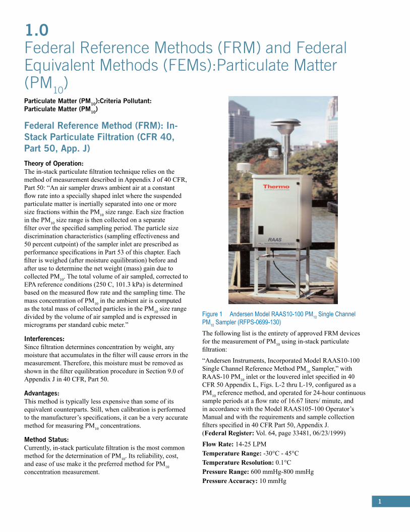
Figure 1 Andersen Model RAAS10-100 PM10 Single Channel PM10 Sampler (RFPS-0699-130) The following list is the entirety of approved FRM devices for the measurement of PM10 using in-stack particulate filtration:
“Andersen Instruments, Incorporated Model RAAS10-100 Single Channel Reference Method PM10 Sampler,” with RAAS-10 PM10 inlet or the louvered inlet specified in 40 CFR 50 Appendix L, Figs. L-2 thru L-19, configured as a PM10 reference method, and operated for 24-hour continuous sample periods at a flow rate of 16.67 liters/ minute, and in accordance with the Model RAAS105-100 Operator’s Manual and with the requirements and sample collection filters specified in 40 CFR Part 50, Appendix J. (Federal Register: Vol. 64, page 33481, 06/23/1999)
Flow Rate: 14-25 LPMTemperature Range: -30°C - 45°CTemperature Resolution: 0.1°CPressure Range: 600 mmHg-800 mmHgPressure Accuracy: 10 mmHg
2
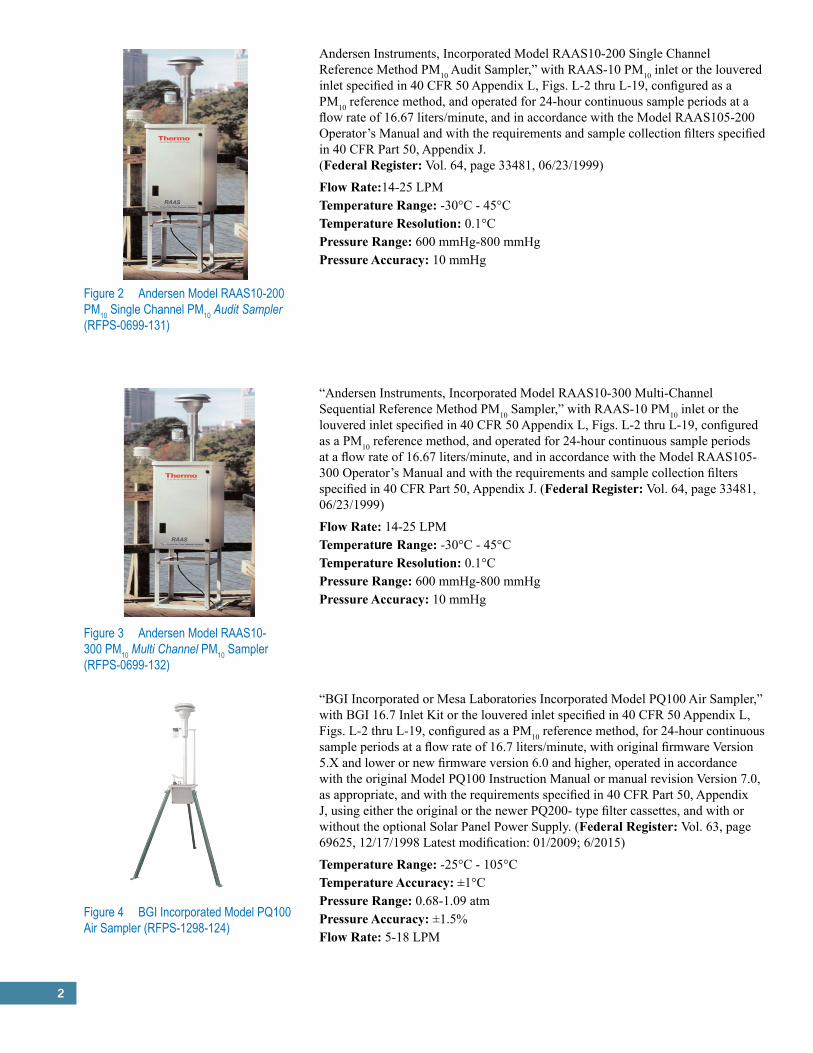
Andersen Instruments, Incorporated Model RAAS10-200 Single Channel Reference Method PM10 Audit Sampler,” with RAAS-10 PM10 inlet or the louvered inlet specified in 40 CFR 50 Appendix L, Figs. L-2 thru L-19, configured as a PM10 reference method, and operated for 24-hour continuous sample periods at a flow rate of 16.67 liters/minute, and in accordance with the Model RAAS105-200 Operator’s Manual and with the requirements and sample collection filters specified in 40 CFR Part 50, Appendix J. (Federal Register: Vol. 64, page 33481, 06/23/1999)
Flow Rate:14-25 LPMTemperature Range: -30°C - 45°CTemperature Resolution: 0.1°CPressure Range: 600 mmHg-800 mmHgPressure Accuracy: 10 mmHg
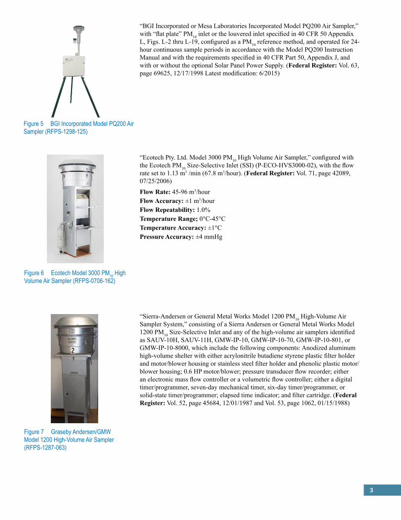
“Andersen Instruments, Incorporated Model RAAS10-300 Multi-Channel Sequential Reference Method PM10 Sampler,” with RAAS-10 PM10 inlet or the louvered inlet specified in 40 CFR 50 Appendix L, Figs. L-2 thru L-19, configured as a PM10 reference method, and operated for 24-hour continuous sample periods at a flow rate of 16.67 liters/minute, and in accordance with the Model RAAS105-300 Operator’s Manual and with the requirements and sample collection filters specified in 40 CFR Part 50, Appendix J. (Federal Register: Vol. 64, page 33481, 06/23/1999)
Flow Rate: 14-25 LPMTemperature Range: -30°C - 45°CTemperature Resolution: 0.1°CPressure Range: 600 mmHg-800 mmHgPressure Accuracy: 10 mmHg
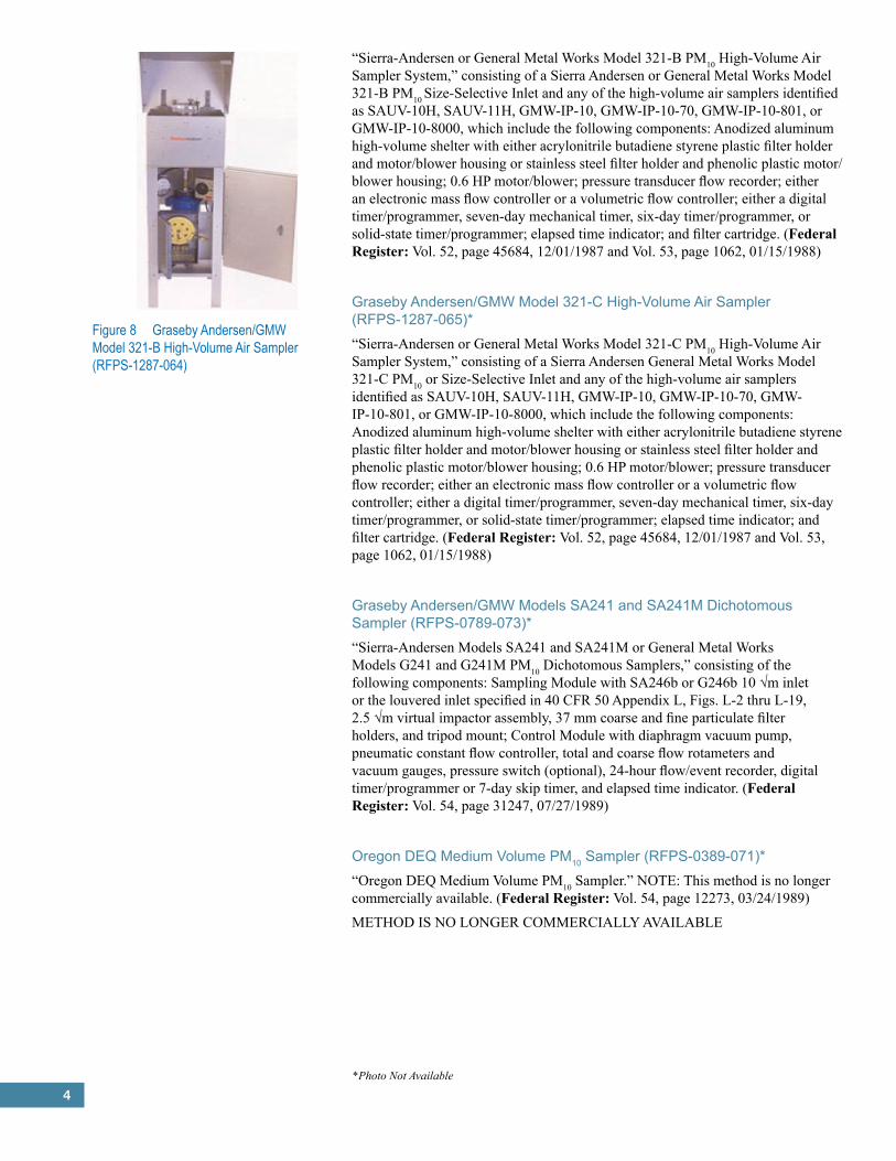
“BGI Incorporated or Mesa Laboratories Incorporated Model PQ100 Air Sampler,” with BGI 16.7 Inlet Kit or the louvered inlet specified in 40 CFR 50 Appendix L, Figs. L-2 thru L-19, configured as a PM10 reference method, for 24-hour continuous sample periods at a flow rate of 16.7 liters/minute, with original firmware Version 5.X and lower or new firmware version 6.0 and higher, operated in accordance with the original Model PQ100 Instruction Manual or manual revision Version 7.0, as appropriate, and with the requirements specified in 40 CFR Part 50, Appendix J, using either the original or the newer PQ200- type filter cassettes, and with or without the optional Solar Panel Power Supply. (Federal Register: Vol. 63, page 69625, 12/17/1998 Latest modification: 01/2009; 6/2015)
Temperature Range: -25°C - 105°CTemperature Accuracy: ±1°CPressure Range: 0.68-1.09 atmPressure Accuracy: ±1.5%Flow Rate: 5-18 LPM
Figure 2 Andersen Model RAAS10-200 PM10 Single Channel PM10 Audit Sampler (RFPS-0699-131)
Figure 3 Andersen Model RAAS10-300 PM10 Multi Channel PM10 Sampler (RFPS-0699-132)
Figure 4 BGI Incorporated Model PQ100 Air Sampler (RFPS-1298-124)
3
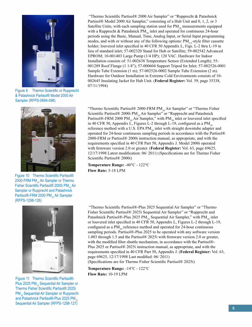
“BGI Incorporated or Mesa Laboratories Incorporated Model PQ200 Air Sampler,” with “flat plate” PM10 inlet or the louvered inlet specified in 40 CFR 50 Appendix L, Figs. L-2 thru L-19, configured as a PM10 reference method, and operated for 24- hour continuous sample periods in accordance with the Model PQ200 Instruction Manual and with the requirements specified in 40 CFR Part 50, Appendix J, and with or without the optional Solar Panel Power Supply. (Federal Register: Vol. 63, page 69625, 12/17/1998 Latest modification: 6/2015)
Figure 5 BGI Incorporated Model PQ200 Air Sampler (RFPS-1298-125)
“Ecotech Pty. Ltd. Model 3000 PM10 High Volume Air Sampler,” configured with the Ecotech PM10 Size-Selective Inlet (SSI) (P-ECO-HVS3000-02), with the flow rate set to 1.13 m3 /min (67.8 m3/hour). (Federal Register: Vol. 71, page 42089, 07/25/2006)
Flow Rate: 45-96 m3/hourFlow Accuracy: ±1 m3/hourFlow Repeatability: 1.0%Temperature Range;� 0°C-45°CTemperature Accuracy: ±1°CPressure Accuracy: ±4 mmHg
“Sierra-Andersen or General Metal Works Model 1200 PM10 High-Volume Air Sampler System,” consisting of a Sierra Andersen or General Metal Works Model 1200 PM10 Size-Selective Inlet and any of the high-volume air samplers identified as SAUV-10H, SAUV-11H, GMW-IP-10, GMW-IP-10-70, GMW-IP-10-801, or GMW-IP-10-8000, which include the following components: Anodized aluminum high-volume shelter with either acrylonitrile butadiene styrene plastic filter holder and motor/blower housing or stainless steel filter holder and phenolic plastic motor/blower housing; 0.6 HP motor/blower; pressure transducer flow recorder; either an electronic mass flow controller or a volumetric flow controller; either a digital timer/programmer, seven-day mechanical timer, six-day timer/programmer, or solid-state timer/programmer; elapsed time indicator; and filter cartridge. (Federal Register: Vol. 52, page 45684, 12/01/1987 and Vol. 53, page 1062, 01/15/1988)
Figure 6 Ecotech Model 3000 PM10 High Volume Air Sampler (RFPS-0706-162)
Figure 7 Graseby Andersen/GMW Model 1200 High-Volume Air Sampler (RFPS-1287-063)
4
“Sierra-Andersen or General Metal Works Model 321-B PM10 High-Volume Air Sampler System,” consisting of a Sierra Andersen or General Metal Works Model 321-B PM10 Size-Selective Inlet and any of the high-volume air samplers identified as SAUV-10H, SAUV-11H, GMW-IP-10, GMW-IP-10-70, GMW-IP-10-801, or GMW-IP-10-8000, which include the following components: Anodized aluminum high-volume shelter with either acrylonitrile butadiene styrene plastic filter holder and motor/blower housing or stainless steel filter holder and phenolic plastic motor/blower housing; 0.6 HP motor/blower; pressure transducer flow recorder; either an electronic mass flow controller or a volumetric flow controller; either a digital timer/programmer, seven-day mechanical timer, six-day timer/programmer, or solid-state timer/programmer; elapsed time indicator; and filter cartridge. (Federal Register: Vol. 52, page 45684, 12/01/1987 and Vol. 53, page 1062, 01/15/1988)
Graseby Andersen/GMW Model 321-C High-Volume Air Sampler (RFPS-1287-065)*“Sierra-Andersen or General Metal Works Model 321-C PM10 High-Volume Air Sampler System,” consisting of a Sierra Andersen General Metal Works Model 321-C PM10 or Size-Selective Inlet and any of the high-volume air samplers identified as SAUV-10H, SAUV-11H, GMW-IP-10, GMW-IP-10-70, GMW-IP-10-801, or GMW-IP-10-8000, which include the following components: Anodized aluminum high-volume shelter with either acrylonitrile butadiene styrene plastic filter holder and motor/blower housing or stainless steel filter holder and phenolic plastic motor/blower housing; 0.6 HP motor/blower; pressure transducer flow recorder; either an electronic mass flow controller or a volumetric flow controller; either a digital timer/programmer, seven-day mechanical timer, six-day timer/programmer, or solid-state timer/programmer; elapsed time indicator; and filter cartridge. (Federal Register: Vol. 52, page 45684, 12/01/1987 and Vol. 53, page 1062, 01/15/1988)
Graseby Andersen/GMW Models SA241 and SA241M Dichotomous Sampler (RFPS-0789-073)*“Sierra-Andersen Models SA241 and SA241M or General Metal Works Models G241 and G241M PM10 Dichotomous Samplers,” consisting of the following components: Sampling Module with SA246b or G246b 10 √m inlet or the louvered inlet specified in 40 CFR 50 Appendix L, Figs. L-2 thru L-19, 2.5 √m virtual impactor assembly, 37 mm coarse and fine particulate filter holders, and tripod mount; Control Module with diaphragm vacuum pump, pneumatic constant flow controller, total and coarse flow rotameters and vacuum gauges, pressure switch (optional), 24-hour flow/event recorder, digital timer/programmer or 7-day skip timer, and elapsed time indicator. (Federal Register: Vol. 54, page 31247, 07/27/1989)
Oregon DEQ Medium Volume PM10 Sampler (RFPS-0389-071)*“Oregon DEQ Medium Volume PM10 Sampler.” NOTE: This method is no longer commercially available. (Federal Register: Vol. 54, page 12273, 03/24/1989)
METHOD IS NO LONGER COMMERCIALLY AVAILABLE
Figure 8 Graseby Andersen/GMW Model 321-B High-Volume Air Sampler (RFPS-1287-064)
*Photo Not Available
5
Figure 9 Thermo Scientific or Rupprecht & Patashnick Partisol® Model 2000 Air Sampler (RFPS-0694-098)
“Thermo Scientific Partisol® 2000 Air Sampler” or “Rupprecht & Patashnick Partisol® Model 2000 Air Sampler,” consisting of a Hub Unit and 0, 1, 2, or 3 Satellite Units, with each sampling station used for PM10 measurements equipped with a Rupprecht & Patashnick PM10 inlet and operated for continuous 24-hour periods using the Basic, Manual, Time, Analog Input, or Serial Input programming modes, and with or without any of the following options: PM2.5-style filter cassette holder; louvered inlet specified in 40 CFR 50 Appendix L, Figs. L-2 thru L-19 in lieu of standard inlet; 57-002320 Stand for Hub or Satellite; 59-002542 Advanced EPROM; 10-001403 Large Pump (1/4 HP); 120 VAC. Hardware for Indoor Installation consists of: 51-002638 Temperature Sensor (Extended Length); 55-001289 Roof Flange (1 1/4”); 57-000604 Support Tripod for Inlet; 57-002526-0001 Sample Tube Extension (1 m); 57-002526-0002 Sample Tube Extension (2 m). Hardware for Outdoor Installation in Extreme Cold Environments consists of 10-002645 Insulating Jacket for Hub Unit. (Federal Register: Vol. 59, page 35338, 07/11/1994)
Figure 10 Thermo Scientific Partisol® 2000-FRM PM10 Air Sampler or Thermo Fisher Scientific Partisol® 2000i PM10 Air Sampler or Rupprecht and Patashnick Partisol®-FRM 2000 PM10 Air Sampler (RFPS-1298-126)
“Thermo Scientific Partisol® 2000-FRM PM10 Air Sampler” or “Thermo Fisher Scientific Partisol® 2000i PM10 Air Sampler” or “Rupprecht and Patashnick Partisol®-FRM 2000 PM10 Air Sampler,” with PM10 inlet or louvered inlet specified in 40 CFR 50, Appendix L, Figures L-2 through L-19, configured as a PM10 reference method with a U.S. EPA PM10 inlet with straight downtube adapter and operated for 24-hour continuous sampling periods in accordance with the Partisol® 2000-FRM or Partisol® 2000i instruction manual, as appropriate, and with the requirements specified in 40 CFR Part 50, Appendix J. Model 2000i operated with firmware version 2.0 or greater. (Federal Register: Vol. 63, page 69625, 12/17/1998 Latest modification: 06/ 2011) (Specifications are for Thermo Fisher Scientific Partisol® 2000i)
Temperature Range: -40°C - 122°CFlow Rate: 5-18 LPM
“Thermo Scientific Partisol®-Plus 2025 Sequential Air Sampler” or “Thermo Fisher Scientific Partisol® 2025i Sequential Air Sampler” or “Rupprecht and Patashnick Partisol®-Plus 2025 PM10 Sequential Air Sampler,” with PM10 inlet or louvered inlet specified in 40 CFR 50, Appendix L, Figures L-2 through L-19, configured as a PM10 reference method and operated for 24-hour continuous sampling periods. Partisol®-Plus 2025 to be operated with any software version 1.003 through 1.5 and the Partisol® 2025i with firmware version 2.0 or greater, with the modified filter shuttle mechanism, in accordance with the Partisol®-Plus 2025 or Partisol® 2025i instruction manual, as appropriate, and with the requirements specified in 40 CFR Part 50, Appendix J. (Federal Register: Vol. 63, page 69625, 12/17/1998 Last modified: 06/ 2011) (Specifications are for Thermo Fisher Scientific Partisol® 2025i)
Temperature Range: -14°C - 122°CFlow Rate: 10-19 LPM
Figure 11 Thermo Scientific Partisol®-Plus 2025 PM10 Sequential Air Sampler or Thermo Fisher Scientific Partisol® 2025i PM10 Sequential Air Sampler or Rupprecht and Patashnick Partisol®-Plus 2025 PM10 Sequential Air Sampler (RFPS-1298-127)
6
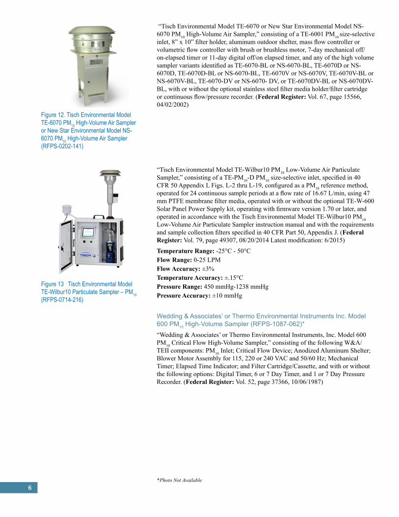
Figure 12. Tisch Environmental Model TE-6070 PM10 High-Volume Air Sampler or New Star Environmental Model NS-6070 PM10 High-Volume Air Sampler (RFPS-0202-141)
“Tisch Environmental Model TE-6070 or New Star Environmental Model NS-6070 PM10 High-Volume Air Sampler,” consisting of a TE-6001 PM10 size-selective inlet, 8” x 10” filter holder, aluminum outdoor shelter, mass flow controller or volumetric flow controller with brush or brushless motor, 7-day mechanical off/on-elapsed timer or 11-day digital off/on elapsed timer, and any of the high volume sampler variants identified as TE-6070-BL or NS-6070-BL, TE-6070D or NS- 6070D, TE-6070D-BL or NS-6070-BL, TE-6070V or NS-6070V, TE-6070V-BL or NS-6070V-BL, TE-6070-DV or NS-6070- DV, or TE-6070DV-BL or NS-6070DV-BL, with or without the optional stainless steel filter media holder/filter cartridge or continuous flow/pressure recorder. (Federal Register: Vol. 67, page 15566, 04/02/2002)
Figure 13 Tisch Environmental Model TE-Wilbur10 Particulate Sampler – PM10 (RFPS-0714-216)
“Tisch Environmental Model TE-Wilbur10 PM10 Low-Volume Air Particulate Sampler,” consisting of a TE-PM10-D PM10 size-selective inlet, specified in 40 CFR 50 Appendix L Figs. L-2 thru L-19, configured as a PM10 reference method, operated for 24 continuous sample periods at a flow rate of 16.67 L/min, using 47 mm PTFE membrane filter media, operated with or without the optional TE-W-600 Solar Panel Power Supply kit, operating with firmware version 1.70 or later, and operated in accordance with the Tisch Environmental Model TE-Wilbur10 PM10 Low-Volume Air Particulate Sampler instruction manual and with the requirements and sample collection filters specified in 40 CFR Part 50, Appendix J. (Federal Register: Vol. 79, page 49307, 08/20/2014 Latest modification: 6/2015)
Temperature Range: -25°C - 50°CFlow Range: 0-25 LPMFlow Accuracy: ±3%Temperature Accuracy: ±.15°CPressure Range: 450 mmHg-1238 mmHgPressure Accuracy: ±10 mmHg
Wedding & Associates’ or Thermo Environmental Instruments Inc. Model 600 PM10 High-Volume Sampler (RFPS-1087-062)*“Wedding & Associates’ or Thermo Environmental Instruments, Inc. Model 600 PM10 Critical Flow High-Volume Sampler,” consisting of the following W&A/TEII components: PM10 Inlet; Critical Flow Device; Anodized Aluminum Shelter; Blower Motor Assembly for 115, 220 or 240 VAC and 50/60 Hz; Mechanical Timer; Elapsed Time Indicator; and Filter Cartridge/Cassette, and with or without the following options: Digital Timer, 6 or 7 Day Timer, and 1 or 7 Day Pressure Recorder. (Federal Register: Vol. 52, page 37366, 10/06/1987)
*Photo Not Available
7
Federal Equivalent Method (FEM): Beta-Attenuation MonitoringTheory of Operation:In a beta-attenuation monitor, a constant source of air is drawn into the monitor through a ribbon filter, which allows particles to collect on the surface. The ribbon is then passed through a detector, in which beta radiation from a source of radiation pass through the particles. The attenuation of the flow of beta radiation is exponentially proportional to the mass of the particles the beta radiation encounters. When calibration is performed to the manufacturer’s specifications, the detector can then determine the intensity of the beta rays that pass through relative to a control sample. From this information, the mass of particles can then be deduced.
Interferences:The beta-attenuation process can be affected by several environmental factors. Moisture in the air, in particular, can affect readings of radiation. Calibration performed to the manufacturer’s specifications must be implemented to guarantee factors such as humidity, temperature, and pressure does not cause error.
Advantages:Unlike filter-based measurement of particulate matter, beta attenuation monitoring is a continuous process with measurements being performed and data collected on an hourly basis. Instrument precision is also much better than that which is observed in filter-based (FRM) methods.
Method Status:Beta attenuation monitors are the second most common type of system used in PM10 monitoring networks after FRM (filter-based) systems. It is a reliable and proved method of particle measurement, with a variety of configurations and options that can be used. The following is the list of approved FEM devices used to measure PM10 based on the beta attenuation method:
The following list is the entirety of approved FEM devices for the measurement of PM10 using beta-attenuation:
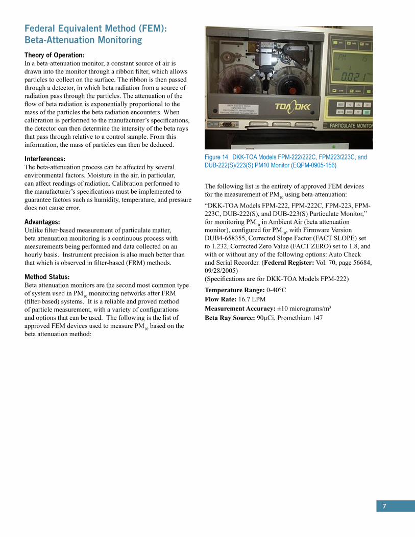
“DKK-TOA Models FPM-222, FPM-222C, FPM-223, FPM-223C, DUB-222(S), and DUB-223(S) Particulate Monitor,” for monitoring PM10 in Ambient Air (beta attenuation monitor), configured for PM10, with Firmware Version DUB4-658355, Corrected Slope Factor (FACT SLOPE) set to 1.232, Corrected Zero Value (FACT ZERO) set to 1.8, and with or without any of the following options: Auto Check and Serial Recorder. (Federal Register: Vol. 70, page 56684, 09/28/2005) (Specifications are for DKK-TOA Models FPM-222)
Temperature Range: 0-40°CFlow Rate: 16.7 LPMMeasurement Accuracy: ±10 micrograms/m3
Beta Ray Source: 90µCi, Promethium 147
Figure 14 DKK-TOA Models FPM-222/222C, FPM223/223C, and DUB-222(S)/223(S) PM10 Monitor (EQPM-0905-156)

8
“Environnement S. A. Model MP101M PM10 Beta Gauge Monitor,” configured with the louvered PM10 inlet specified in 40 CFR 50 Appendix L or its flat-topped predecessor version and one of the three optional temperature-regulated sampling tubes (RST), and operated with a full scale measurement range of 0 - 0.500 mg/m3 (0 - 500 :g/m3 ), with the sample flow rate set to 1.00 m3 /h and flow regulation set to yes, the “norms selection” set to m3 (actual volume), the “cycle” set to 24 hours, the “period” set to none, and the “counting time” set to 200 seconds.2 (Federal Register: Vol. 69, page 18569, 4/8/2004)
Lower Detectable Limit: 0.5 µg/m3
Beta Ray Source: Carbon 14Sampling Flow Rate: 1 m3/hourTemperature Range: 10°C-40°CMeasurement Accuracy: ±5%
Graseby Andersen/GMW Model FH621-N Beta Monitor (EQPM-0990-076)*“Andersen Instruments Model FH62I-N PM10 Beta Attenuation Monitor,” consisting of the following components: FH101 Vacuum Pump Assembly; FH102 Accessory Kit; FH107 Roof Flange Kit; FH125 Zero and Span PM10 Mass Foil Calibration Kit; FH62I Beta Attenuation 19-inch Control Module; SA246b PM10 Inlet (16.7 liter/min) or the louvered inlet specified in 40 CFR 50 Appendix L, Figs. L-2 thru L-19; operated for 24-hour average measurements, with an observing time of 60 minutes, the calibration factor set to 2400, a glass fiber filter tape, an automatic filter advance after each 24-hour sample period, and with or without either of the following options: FH0P1 Indoor Cabinet; FH0P2 Outdoor Shelter Assembly. (Federal Register: Vol. 55, page 38387, 09/18/1990)
“Met One Instruments or Sibata Scientific Technology Models BAM 1020, GBAM 1020, BAM 1020-1, GBAM 1020-1, Horiba APDA-371 PM10 Beta Attenuation Monitor, or Ecotech Spirant BAM1000” including the BX-802 EPA PM10 inlet (or alternative louvered PM10 inlet meeting 40 CFR 50 Appendix L specifications), operated for 24-hour average measurements, with a filter change frequency of one hour, with glass fiber filter tape, and with or without any of the following options: BX- 823, tube extension; BX-825, heater kit; BX-826, 230 VAC heater kit; BX-827 “Smart Heater” set for maintaining moisture between 35% and 45% and no ΔT control; BX-828, roof tripod; BX-902, exterior enclosure; BX-903, exterior enclosure with temperature control; BX-961, mass flow controller; BX-967, internal calibration device, BX-970 touch-screen display with USB interface. For software (firmware) versions V3.0 or higher, a user-selectable measurement time (COUNT TIME) of 4, 6, 8 or 10 minutes selected, along with appropriate sample time (BAM SAMPLE) setting of 50, 46, 42 or 38 minutes, respectively, to maintain a 60-minute measurement cycle. For software (firmware) versions V3.5 or higher, user-selectable option to sample under actual conditions (Flow Type: ACTUAL) and report under standard conditions (Reporting: STD), which requires the use of P/N BX-592 external temperature sensor or P/N BX-596 external temperature/barometric pressure sensor. The user may also sample under standard conditions (Flow Type: STD) and report under standard conditions (Reporting: STD) with any software/firmware 2.0 or higher. Instrument must be operated in accordance with the appropriate instrument manual. (Federal Register: Vol. 63, page 41253, 08/03/1998 Latest modifications: 06/2009; 07/2010; 8/2010; 8/2012) (Specifications are for Met One BAM-1020)
Temperature Range: 0°C - 50°CFlow Rate: 16.7 LPMLower Detectable Limit: <4.8 µg/m3 (hourly), <1.0 µg/m3 (24 hours)Beta Ray Source: Carbon 14
Figure 15 Environnement S.A. Model MP101M PM10 Monitor (EQPM-0404-151)
Figure 16 Met One or Sibata Models BAM/GBAM 1020, BAM/GBAM 1020-1, Horiba APDA-371, or Ecotech Spirant BAM1000 (EQPM-0798-122)
*Photo Not Available

9
“Opsis Model SM200 Monitor,” beta gauge semi-continuous ambient particulate monitor operated for 24 hours at a flow rate of 16.67 LPM between 5° and 40°C using 47 mm PTFE membrane filter media, in the mass measurement range of 0 to 60 mg, configured with a BGI Model SSI25 PM10 inlet meeting criteria specified in 40 CFR 50 Appendix L, with a roof mounting kit, and with or without an inlet tube heater (as recommended based on site RH conditions), according to the SM200 User’s Guide. (Federal Register: Vol. 75, page 51039, 08/18/2010)
Flow Rate: 8-25 LPMFlow Rate Accuracy: ±2%Beta Ray Source: Carbon 14Temperature Range: 5°C-35°C
Figure 17 Opsis Model SM200 PM10 Monitor (EQPM-0810-193)
Figure 18 Teledyne Model 602 BetaPLUS Particle Measurement System or SWAM 5a Dual Channel Monitor (EQPM-0912-205)
“Teledyne Model 602 BetaPLUS Particle Measurement System” or “SWAM 5a Dual Channel Monitor” configured for 1-hour measurements of PM10 by beta attenuation on a single sampling line (Line A or B, but not both together), with the standard, louvered US EPA PM10 size selective inlet specified in 40 CFR 50 Appendix L, using 47 mm glass fiber filters, at a sample flow set to 16.67 liters/min and software version 05-02.07.63 or later. Operated in accordance with the Teledyne Model 602 BetaPLUS Particle Measurement System Operation Manual. (Federal Register: Vol. 77, page 60985, 10/5/2012) (Specifications are for Teledyne Model 602 BetaPLUS)
Flow Rate: 0.8-2.5 m3/hourFlow Rate Accuracy: ±1%Lower Detectable Limit: 3.0 µg/m3 (hour)Precision: ±1.0 µg/m3
Temperature Range: 0°C-50°C
Figure 19 Thermo Andersen Series FH 62 C14 Continuous PM10 Monitor Thermo Scientific Model 5014i Beta (5014i Beta), Continuous Ambient Particulate Monitor (EQPM-1102-150)
“Thermo Andersen Series FH 62 C14 Continuous PM10 Ambient Particulate Monitor and Thermo Scientific Model 5014i Beta (5014i Beta), Continuous Ambient Particulate Monitor,” operated for 24-hour average measurements, with the specified 10- micron EPA PM10 inlet (or alternative louvered PM10 inlet meeting 40 CFR 50 Appendix L specifications), inlet connector, sample tube with heater, roof flange kit, mass foil kit, pump kit, sample filter tape; with operational settings of 1000 L/h (16.67 L/min) sample flow rate, daily filter change, auto filter change at volumetric flow 1500 micrograms, and factory default calculation mode settings operated with software version 1.07. Operated, calibrated and serviced according to the appropriate Operator Manual. (Federal Register: Vol. 67, page 76174, 12/11/2002 Latest modifications: 07/2009; 12/2012) (Specifications are for Thermo Scientific Model 5014i Beta)
Measurement Accuracy: ±5%Flow Rate: 16.7 LPMMeasurement Precision: ±2.0 µg/m2
Temperature Range: -30°C - 50°C
Wedding & Associates’ or Thermo Environmental Instruments Inc. Model 650 PM10 Beta Gauge (EQPM-0391-081)*“Wedding & Associates’ or Thermo Environmental Instruments, Inc. Model 650 PM10 Beta Gauge Automated Particle Sampler,” consisting of the following W&A/TEII components: Particle Sampling Module, PM10 Inlet (18.9 liter/min), Inlet Tube and Support Ring, Vacuum Pump (115, 220 or 240 VAC and 50/60 Hz); and operated for 24-hour average measurements with glass fiber filter tape. (Federal Register: Vol. 56, page 9216, 03/05/1991)*Photo Not Available
10
Federal Equivalent Method (FEM): Tapered Element Oscillating Microbalance (TEOM®)Theory of Operation:An air sample is pulled into the TEOM® monitor through a filter, which removes potential interferences. The filtered air then passes to the microbalance, where molecules collect on the tapered oscillating element. This collection of mass changes the frequency of oscillation, and, based on the correlation between mass and frequency, particle mass can be calculated.
Interferences:Since TEOM® monitors rely on the frequency of a sensitive oscillating element; mechanical noise may interfere with calculation. Additionally, dramatic temperature fluctuations can also cause errors from the microbalance.
Advantages:As a continuous method, TEOM® provides regular real-time measurements of PM10 concentrations. In addition, under ideal conditions (e.g., temperature, relative humidity, mass flow rate, etc.), the method is just as accurate as the reference method.
Method Status:There are only two approved monitors using the TEOM® method. While under the correct conditions this method is reliable, it sensitivity presents complications in urban environments, where PM10 concentrations are of the most concern.
The following list is the entirety of approved FEM devices for the measurement of PM10 using TEOM®:
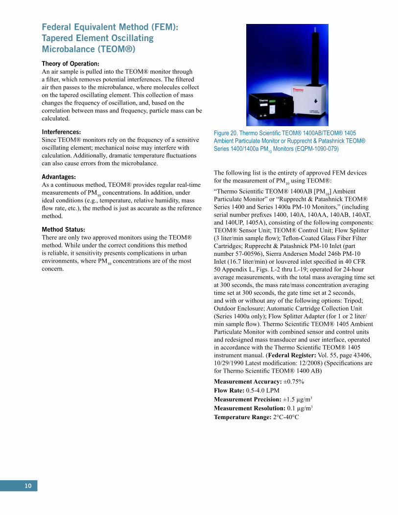
“Thermo Scientific TEOM® 1400AB [PM10] Ambient Particulate Monitor” or “Rupprecht & Patashnick TEOM® Series 1400 and Series 1400a PM-10 Monitors,” (including serial number prefixes 1400, 140A, 140AA, 140AB, 140AT, and 140UP, 1405A), consisting of the following components: TEOM® Sensor Unit; TEOM® Control Unit; Flow Splitter (3 liter/min sample flow); Teflon-Coated Glass Fiber Filter Cartridges; Rupprecht & Patashnick PM-10 Inlet (part number 57-00596), Sierra Andersen Model 246b PM-10 Inlet (16.7 liter/min) or louvered inlet specified in 40 CFR 50 Appendix L, Figs. L-2 thru L-19; operated for 24-hour average measurements, with the total mass averaging time set at 300 seconds, the mass rate/mass concentration averaging time set at 300 seconds, the gate time set at 2 seconds, and with or without any of the following options: Tripod; Outdoor Enclosure; Automatic Cartridge Collection Unit (Series 1400a only); Flow Splitter Adapter (for 1 or 2 liter/min sample flow). Thermo Scientific TEOM® 1405 Ambient Particulate Monitor with combined sensor and control units and redesigned mass transducer and user interface, operated in accordance with the Thermo Scientific TEOM® 1405 instrument manual. (Federal Register: Vol. 55, page 43406, 10/29/1990 Latest modification: 12/2008) (Specifications are for Thermo Scientific TEOM® 1400 AB)
Measurement Accuracy: ±0.75%Flow Rate: 0.5-4.0 LPMMeasurement Precision: ±1.5 µg/m3
Measurement Resolution: 0.1 µg/m3
Temperature Range: 2°C-40°C
Figure 20. Thermo Scientific TEOM® 1400AB/TEOM® 1405 Ambient Particulate Monitor or Rupprecht & Patashnick TEOM® Series 1400/1400a PM10 Monitors (EQPM-1090-079)

11
Figure 21 Thermo Scientific TEOM® 1405-DF Dichotomous Ambient Particulate Monitor with FDMS® (EQPM-1013-208)
“Thermo Scientific TEOM® 1405-DF Dichotomous Ambient Particulate Monitor with FDMS®,” configured for dual filter sampling of fine (PM2.5) and coarse particles using the US EPA PM10 inlet specified in 40 CFR 50 Appendix L, Figs. L-2 thru L-19 and a virtual impactor, with a total flow rate of 16.67 L/min, fine sample flow of 3 L/min, and coarse sample flow rate of 1.67 L/min, and operating with firmware version 1.70 and later, operated with or without external enclosures, and operated in accordance with the Thermo Scientific TEOM® 1405-DF Dichotomous Ambient Particulate Monitor Instruction Manual. This designation applies to PM10 measurements only. (Federal Register: Vol. 78, page 67360, 11/12/2013)
Measurement Accuracy: ±0.75%Flow Rate: 12 LPMMeasurement Precision: ±2 µg/m3 (hour), ±1 µg/m3 (24 hours)Measurement Resolution: 0.1 µg/m3
Temperature Range: 8°C-25°C

12
Federal Equivalent Method (FEM): Dichotomous Air SamplerTheory of Operation:In a dichotomous air sampler, air is drawn into an inlet and separated by size. Particles then collect on a Teflon® filter. The filter is then analyzed with either neutron activation analysis or X-ray fluorescence spectroscopy.
Interferences:Assuming that the method is operated with calibration performed to the manufacturer’s specifications, potential interferences are negligible.
Advantages:Beta attenuation monitors are the second most common type of system used in PM10 monitoring networks after FRM (filter-based) systems. It is a reliable and proved method of particle measurement, with a variety of configurations and options that can be used. The following is the list of approved FEM devices used to measure PM10 based on the beta attenuation method:
Method Status:There are currently two dichotomous air samplers approved by the EPA. These devices are accurate and easy to use, and can cover a wide range of particles that need monitoring.
“Thermo Scientific Dichotomous Partisol®-Plus 2025-D Sequential Air Sampler” or “Thermo Fisher Scientific Dichotomous Partisol® 2025i-D Sequential Air Sampler,” configured for dual-filter sampling of fine (PM2.5) and coarse (PM10-2.5) particles, with a U.S. EPA PM10 inlet and using a virtual impactor to separate the fine and coarse PM into two samples for collection on two separate filter membranes, and operated with the modified filter shuttle mechanism implemented May 31, 2008, and firmware version 1.500 or greater for the Partisol®-Plus 2025-D and version 2.0 or greater for the Partisol® 2025i-D, for 24-hour continuous sampling periods, in accordance with the Partisol®-Plus 2025-D or Partisol® 2025i-D instruction manual, as appropriate. (Federal Register: Vol. 76, page 15975, 03/22/2011 Latest modification: 06/ 2011) (Specifications are for Thermo Fisher Scientific Dichotomous Partisol® 2025i-D)
Flow Rate: 10-19 LPMTemperature Range: -40°C-50°C
Figure 23 Thermo Scientific Dichotomous Partisol®-Plus 2025-D Sequential Air Sampler or Thermo Fisher Scientific Dichotomous Partisol® 2025i-D Sequential Air Sampler (EQPS-0311-198)
Figure 22 Thermo Scientific Partisol® 2000-D Dichotomous Air Sampler or Thermo Fisher Scientific Partisol® 2000i-D Dichotomous Air Sampler (EQPS-0311-197)
The following list is the entirety of approved FEM dichotomous air sampling devices for the measurement of PM10:
“Thermo Scientific Partisol® 2000-D Dichotomous Air Sampler” or “Thermo Fisher Scientific Partisol® 2000i-D Dichotomous Air Sampler,” configured for dual-filter, single-event sampling of fine (PM2.5) and coarse (PM10-2.5) particles, operated with a U.S. EPA PM10 inlet and using a virtual impactor to separate fine and coarse PM into two samples for collection on two separate filter membranes, for a 24-hour sampling period and in accordance with the Partisol® 2000-D or Partisol® 2000i-D instruction manual, as appropriate. Partisol® 2000i-D operated with firmware version 2.0 or greater. (Federal Register: Vol. 76, page 15974, 03/22/2011 Latest modification: 06/2011) (Specifications are for Thermo Fisher Scientific Partisol® 2000i-D)
Temperature Range: -40°C - 50°C
13
2.0 Federal Reference Methods (FRM) and Federal Equivalent Methods (FEMs):Particulate Matter (PM2.5)Particulate Matter (PM2.5):Criteria Pollutant: Particulate Matter (PM2.5)
Federal Reference Method (FRM): In-stack Particulate Filtration (CFR 40, Part 50, App. L)Theory of Operation:The volumetric flow rate must be controlled automatically as specified in Section 7.1 (a) of Appendix L in 40 CFR, Part 50. The volumetric flow rate measurement requirements/capabilities are specified in Section 7.4 (and subsequent subsections) of Appendix L in 40 CFR, Part 50. The in-stack particulate filtration technique relies on the method of measurement described in Appendix L of 40 CFR, Part 50 “An electrically powered air sampler draws ambient air at a constant volumetric flow rate into a specially shaped inlet and through an inertial particle size separator (impactor) where the suspended particulate matter in the PM2.5 size range is separated for collection on a polytetrafluoroethylene (PTFE) filter over the specified sampling period. Each filter is weighed (after moisture and temperature conditioning) before and after sample collection to determine the net gain due to collected PM2.5. The total volume of air sampled is determined by the sampler from the measured flow rate at actual ambient temperature and pressure and the sampling time. The mass concentration of PM2.5 in the ambient air is computed as the total mass of collected particles in the PM2.5 size range divided by the actual volume of air sampled, and is expressed in micrograms per cubic meter of air.”
Interferences:Moisture will often collect in the filter, which will cause errors in the measurement of collected particulate mass. Therefore, all of this moisture must be removed to provide an accurate measurement.
Advantages:In-stack particulate filtration is a less expensive method for measurement of particulate matter. Still, it provides accurate and understandable measurements for concentrations of PM2.5.
Method Status:Currently, in-stack particulate filtration is the most common method for the determination of PM2.5 concentrations. It reliability, cost, and ease of use make it the preferred method for PM2.5 concentration measurement.
The following list is the entirety of approved FRM devices for the measurement of PM2.5 using in-stack particulate filtration:
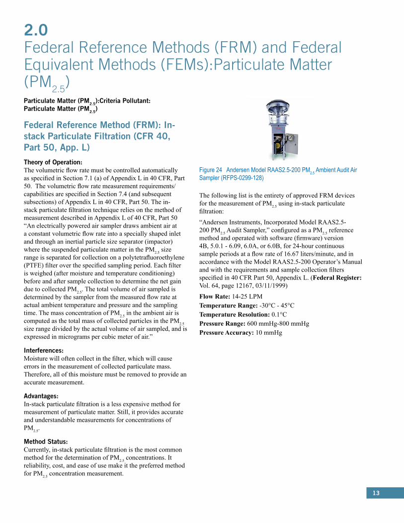
“Andersen Instruments, Incorporated Model RAAS2.5-200 PM2.5 Audit Sampler,” configured as a PM2.5 reference method and operated with software (firmware) version 4B, 5.0.1 - 6.09, 6.0A, or 6.0B, for 24-hour continuous sample periods at a flow rate of 16.67 liters/minute, and in accordance with the Model RAAS2.5-200 Operator’s Manual and with the requirements and sample collection filters specified in 40 CFR Part 50, Appendix L. (Federal Register: Vol. 64, page 12167, 03/11/1999)
Flow Rate: 14-25 LPMTemperature Range: -30°C - 45°CTemperature Resolution: 0.1°CPressure Range: 600 mmHg-800 mmHgPressure Accuracy: 10 mmHg
Figure 24 Andersen Model RAAS2.5-200 PM2.5 Ambient Audit Air Sampler (RFPS-0299-128)

14
Figure 25 BGI Inc. Models PQ200 or PQ200A PM2.5 Ambient Fine Particle Sampler (RFPS-0498-116)
“BGI Incorporated or Mesa Laboratories Incorporated Models PQ200 and PQ200A PM2.5 Ambient Fine Particle Sampler,” operated with firmware version 3.88 or 3.89R, for 24-hour continuous sample periods, in accordance with the Model PQ200/PQ200A Instruction Manual and with the requirements and sample collection filters specified in 40 CFR Part 50, Appendix L, and with or without the optional Solar Power Supply or the optional dual-filter cassette (P/N F-21/6) and associated lower impactor housing (P/N B2027), where the upper filter is used for PM2.5. The Model PQ200A is described as a portable audit sampler and includes a set of three carrying cases. (Federal Register: Vol. 63, page 18911, 04/16/1998 Latest modification: 6/2015)
Flow Rate: 14-25 LPMTemperature Range: -30°C - 45°CTemperature Resolution: 0.1°CPressure Range: 600 mmHg-800 mmHgPressure Accuracy: 10 mmHg
Figure 26 Graseby Andersen Model RAAS2.5-100 PM2.5 Ambient Air Sampler (RFPS-0598-119)
“Graseby Andersen Model RAAS2.5-100 PM2.5 Ambient Air Sampler,” operated with software version 4B, 5.0.1 - 6.09, 6.0A, or 6.0B, configured for “Single 2.5” operation, for 24-hour continuous sample periods at a flow rate of 16.67 liters/minute, and in accordance with the Model RAAS2.5-100 Operator’s Manual and with the requirements and sample collection filters specified in 40 CFR Part 50, Appendix L. (Federal Register: Vol. 63, page 31991, 06/11/1998)
Flow Rate: 14-25 LPMTemperature Range: -30°C-45°CTemperature Resolution: 0.1°CPressure Range: 600 mmHg-800 mmHgPressure Accuracy: 10 mmHg
Figure 27 Graseby Andersen Model RAAS2.5-300 PM2.5 Sequential Ambient Air Sampler (RFPS-0598-120)
“Graseby Andersen Model RAAS2.5-300 PM2.5 Sequential Ambient Air Sampler,” operated with software version 4B, 5.0.1 - 6.09, 6.0A, or 6.0B, configured for “Multi 2.5” operation, for 24-hour continuous sample periods at a flow rate of 16.67 liters/minute, and in accordance with the Model RAAS2.5-300 Operator’s Manual and with the requirements and sample collection filters specified in 40 CFR Part 50, Appendix L. (Federal Register: Vol. 63, page 31991, 06/11/1998)

15
“Met One Instruments, Inc. e-FRM ,” configured for filter sampling of ambient particles using the US EPA PM10 inlet specified in 40 CFR 50 Appendix L, Figs. L-2 thru L-19, equipped with either a BGI VSCCTM cyclone or WINS PM2.5 fractionator, with a flow rate of 16.67 L/min, using 47 mm PTFE membrane filter media, and operating with firmware version R1.1.0 and later, and operated in accordance with the Met One e-FRM PM2.5 operating manual. (Federal Register: Vol. 80, page 32114, 6/05/2015)
Figure 28 Met One e-FRM– PM2.5 (RFPS-0315-221)
Figure 29 Rupprecht & Patashnick Partisol®-FRM Model 2000 PM2.5 Air Sampler (RFPS-0498-117)
“Rupprecht & Patashnick Company, Incorporated Partisol®-FRM Model 2000 PM2.5 Air Sampler,” operated with software versions 1.102 - 1.202, with either R&P-specified machined or molded filter cassettes, with or without the optional insulating jacket for cold weather operation, for 24-hour continuous sample periods, in accordance with the Model 2000 Instruction Manual and with the requirements and sample collection filters specified in 40 CFR Part 50, Appendix L. (Federal Register: Vol. 63, page 18911, 04/16/1998)
Figure 30 Rupprecht & Patashnick Partisol® Model 2000 PM2.5 Audit Sampler (RFPS-0499-129)
“Rupprecht & Patashnick Company, Inc. Partisol ® Model 2000 PM2.5 Audit Sampler,” configured as a PM2.5 reference method and operated with software (firmware) version 1.2 - 1.202, for 24-hour continuous sample periods at a flow rate of 16.67 liters/minute, in accordance with the Partisol® Model 2000 Operating Manual and with the requirements and sample collection filters specified in 40 CFR Part 50, Appendix L. (Federal Register: Vol. 64, page 19153, 04/19/1999)

16
Figure 31 Rupprecht & Patashnick Partisol®-Plus Model 2025 Sequential Air Sampler (RFPS-0498-118)
“Rupprecht & Patashnick Company, Incorporated Partisol®-Plus Model 2025 PM2.5 Sequential Air Sampler,” operated with any software version 1.003 through 1.4.16, with either R&P-specified machined or molded filter cassettes, for 24-hour continuous sample periods, in accordance with the Model 2025 Instruction Manual and with the requirements and sample collection filters specified in 40 CFR Part 50, Appendix L. (Federal Register: Vol. 63, page 18911, 04/16/1998)
“Tisch Environmental Model TE-Wilbur2.5 PM2.5 Low-Volume Air Particulate Sampler,” configured as a PM2.5 reference method, with firmware version 1.70 or later and a TE-PM10-D PM10 size-selective inlet as specified in 40 CFR 50 Appendix L Figs. L-2 thru L-19, with either a BGI VSCC™ Very Sharp Cut Cyclone particle size separator or WINS impactor, and operated for 24 sample periods at a flow rate of 16.67 L/min, using 47 mm PTFE membrane filter media, operated with or without the optional TE-W-600 Solar Panel Power Supply kit, and in accordance with the Tisch Environmental Model TEWilbur2.5 PM2.5 Low-Volume Air Particulate Sampler instruction manual and with the requirements and sample collection filters as specified in 40 CFR Part 50, Appendix L. (Federal Register: Vol. 79, page 65392, 11/04/2014 Latest modification: 6/2015)
Temperature Range: -25°C - 50°CFlow Range: 0-25 LPMFlow Accuracy: ±3%Temperature Accuracy: ±.15°CPressure Range: 450 mmHg-1238 mmHgPressure Accuracy: ±10 mmHg
URG-MASS100 Single PM2.5 FRM Sampler (RFPS-0400-135)* “URG-MASS100 Single PM2.5 FRM Sampler,” operated with software (firmware) version 4B or 5.0.1, configured for “Single 2.5” operation, for 24-hour continuous sample periods at a flow rate of 16.67 liters/minute, and in accordance with the URGMASS100 Operator’s Manual and with the requirements and sample collection filters specified in 40 CFR Part 50, Appendix L. (Federal Register: Vol. 65, page 26603, 05/08/2000)
URG-MASS300 Sequential PM2.5 FRM Sampler (RFPS-0400-136)* “URG-MASS300 Sequential PM2.5 FRM Sampler,” operated with software (firmware) version 4B or 5.0.1, configured for “Multi 2.5” operation, for 24-hour continuous sample periods at a flow rate of 16.67 liters/minute, and in accordance with the URG-MASS300 Operator’s Manual and with the requirements and sample collection filters specified in 40 CFR Part 50, Appendix L. (Federal Register: Vol. 65, page 26603, 05/08/2000)
Figure 32 Tisch Environmental Model TE-Wilbur2.5 Particulate Sampler – PM2.5 (RFPS-1014-219)
Thermo Environmental Instruments, Incorporated Model 605 “CAPS” Sampler (RFPS-1098-123)*“Thermo Environmental Instruments, Incorporated Model 605 “CAPS” Computer Assisted Particle Sampler,” configured as a PM2.5 reference method and operated with software version 1.02A, for 24-hour continuous sample periods, in accordance with the Model 605 Instruction Manual and with the requirements and sample collection filters specified in 40 CFR Part 50, Appendix L. (Federal Register: Vol. 63, page 58036, 10/29/1998)
*Photo Not Available
17
Federal Equivalent Method (FEM): Beta-Attenuation MonitoringTheory of Operation:In a beta-attenuation monitor, a constant source of air is drawn into the monitor through a ribbon filter, which allows particles to collect on the surface. The ribbon is then passed through a detector, in which beta rays from a source of radiation pass through the particles. When calibration is performed to the manufacturer’s specifications, the detector can then determine the intensity of the beta rays that pass through relative to a control sample. From this information, the mass of particles can then be deduced.
Interferences:The beta-attenuation process can be affected by several environmental factors. Moisture in the air, in particular, can affect readings of radiation. Proper calibration must be put in place to guarantee factors such as humidity, temperature, and pressure do not cause error.
Advantages:Unlike in-stack filtration, the process for beta-attenuation is a continuous process, with filters only needing to be changed every 24 hours. Precision is also much better than what is seen in its FRM counterpart.
Method Status:Beta-attenuation is the second most common method for measurement for PM2.5. It is a reliable, proven method of measurement, and there are a variety of options available using this method.
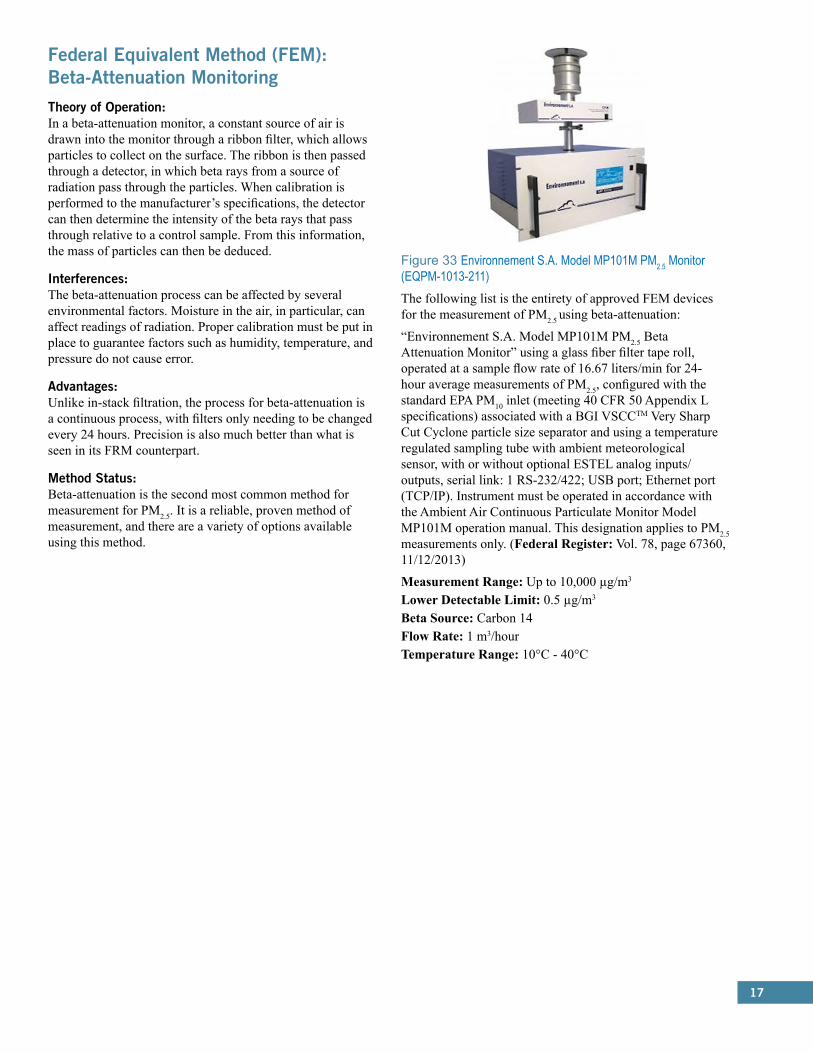
Figure 33 Environnement S.A. Model MP101M PM2.5 Monitor (EQPM-1013-211) The following list is the entirety of approved FEM devices for the measurement of PM2.5 using beta-attenuation:
“Environnement S.A. Model MP101M PM2.5 Beta Attenuation Monitor” using a glass fiber filter tape roll, operated at a sample flow rate of 16.67 liters/min for 24-hour average measurements of PM2.5, configured with the standard EPA PM10 inlet (meeting 40 CFR 50 Appendix L specifications) associated with a BGI VSCCTM Very Sharp Cut Cyclone particle size separator and using a temperature regulated sampling tube with ambient meteorological sensor, with or without optional ESTEL analog inputs/outputs, serial link: 1 RS-232/422; USB port; Ethernet port (TCP/IP). Instrument must be operated in accordance with the Ambient Air Continuous Particulate Monitor Model MP101M operation manual. This designation applies to PM2.5 measurements only. (Federal Register: Vol. 78, page 67360, 11/12/2013)
Measurement Range: Up to 10,000 µg/m3
Lower Detectable Limit: 0.5 µg/m3
Beta Source: Carbon 14Flow Rate: 1 m3/hourTemperature Range: 10°C - 40°C
18
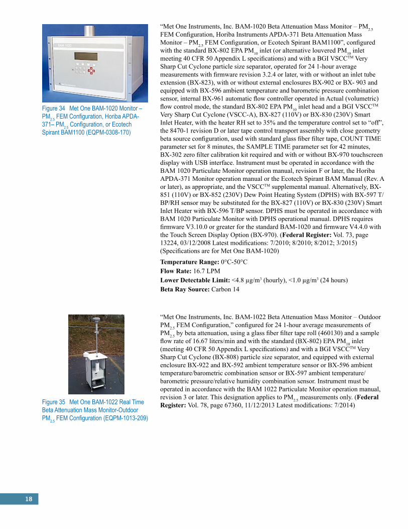
Figure 34 Met One BAM-1020 Monitor – PM2.5 FEM Configuration, Horiba APDA-371– PM2.5 Configuration, or Ecotech Spirant BAM1100 (EQPM-0308-170)
“Met One Instruments, Inc. BAM-1020 Beta Attenuation Mass Monitor – PM2.5 FEM Configuration, Horiba Instruments APDA-371 Beta Attenuation Mass Monitor – PM2.5 FEM Configuration, or Ecotech Spirant BAM1100”, configured with the standard BX-802 EPA PM10 inlet (or alternative louvered PM10 inlet meeting 40 CFR 50 Appendix L specifications) and with a BGI VSCCTM Very Sharp Cut Cyclone particle size separator, operated for 24 1-hour average measurements with firmware revision 3.2.4 or later, with or without an inlet tube extension (BX-823), with or without external enclosures BX-902 or BX- 903 and equipped with BX-596 ambient temperature and barometric pressure combination sensor, internal BX-961 automatic flow controller operated in Actual (volumetric) flow control mode, the standard BX-802 EPA PM10 inlet head and a BGI VSCCTM Very Sharp Cut Cyclone (VSCC-A), BX-827 (110V) or BX-830 (230V) Smart Inlet Heater, with the heater RH set to 35% and the temperature control set to “off”, the 8470-1 revision D or later tape control transport assembly with close geometry beta source configuration, used with standard glass fiber filter tape, COUNT TIME parameter set for 8 minutes, the SAMPLE TIME parameter set for 42 minutes, BX-302 zero filter calibration kit required and with or without BX-970 touchscreen display with USB interface. Instrument must be operated in accordance with the BAM 1020 Particulate Monitor operation manual, revision F or later, the Horiba APDA-371 Monitor operation manual or the Ecotech Spirant BAM Manual (Rev. A or later), as appropriate, and the VSCCTM supplemental manual. Alternatively, BX-851 (110V) or BX-852 (230V) Dew Point Heating System (DPHS) with BX-597 T/BP/RH sensor may be substituted for the BX-827 (110V) or BX-830 (230V) Smart Inlet Heater with BX-596 T/BP sensor. DPHS must be operated in accordance with BAM 1020 Particulate Monitor with DPHS operational manual. DPHS requires firmware V3.10.0 or greater for the standard BAM-1020 and firmware V4.4.0 with the Touch Screen Display Option (BX-970). (Federal Register: Vol. 73, page 13224, 03/12/2008 Latest modifications: 7/2010; 8/2010; 8/2012; 3/2015) (Specifications are for Met One BAM-1020)
Temperature Range: 0°C-50°CFlow Rate: 16.7 LPMLower Detectable Limit: <4.8 µg/m3 (hourly), <1.0 µg/m3 (24 hours)Beta Ray Source: Carbon 14
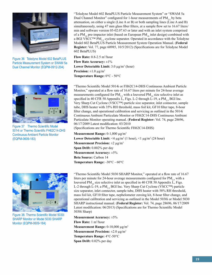
Figure 35 Met One BAM-1022 Real Time Beta Attenuation Mass Monitor-Outdoor PM2.5 FEM Configuration (EQPM-1013-209)
“Met One Instruments, Inc. BAM-1022 Beta Attenuation Mass Monitor – Outdoor PM2.5 FEM Configuration,” configured for 24 1-hour average measurements of PM2.5 by beta attenuation, using a glass fiber filter tape roll (460130) and a sample flow rate of 16.67 liters/min and with the standard (BX-802) EPA PM10 inlet (meeting 40 CFR 50 Appendix L specifications) and with a BGI VSCCTM Very Sharp Cut Cyclone (BX-808) particle size separator, and equipped with external enclosure BX-922 and BX-592 ambient temperature sensor or BX-596 ambient temperature/barometric combination sensor or BX-597 ambient temperature/barometric pressure/relative humidity combination sensor. Instrument must be operated in accordance with the BAM 1022 Particulate Monitor operation manual, revision 3 or later. This designation applies to PM2.5 measurements only. (Federal Register: Vol. 78, page 67360, 11/12/2013 Latest modifications: 7/2014)
19
Figure 36 Teledyne Model 602 BetaPLUS Particle Measurement System or SWAM 5a Dual Channel Monitor (EQPM-0912-204)
“Teledyne Model 602 BetaPLUS Particle Measurement System” or “SWAM 5a Dual Channel Monitor” configured for 1-hour measurements of PM2.5 by beta attenuation, on either a single (Line A or B) or both sampling lines (Line A and B) simultaneously, using 47 mm glass fiber filters, at a sample flow set to 16.67 liters/min and software version 05-02.07.63 or later and with an inlet system comprised of a PM10 pre-impactor inlet (based on European PM10 inlet design) combined with a BGI VSCC™ PM2.5 cyclone separator. Operated in accordance with the Teledyne Model 602 BetaPLUS Particle Measurement System Operation Manual. (Federal Register: Vol. 77, page 60985, 10/5/2012) (Specifications are for Teledyne Model 602 BetaPLUS)
Flow Rate: 0.8-2.5 m3/hourFlow Rate Accuracy: ±1%Lower Detectable Limit: 3.0 µg/m3 (hour)Precision: ±1.0 µg/m3
Temperature Range: 0°C - 50°C
Figure 37 Thermo Scientific Model 5014i or Thermo Scientific FH62C14-DHS Continuous Ambient Particle Monitor (EQPM-0609-183)
“Thermo Scientific Model 5014i or FH62C14-DHS Continuous Ambient Particle Monitor,” operated at a flow rate of 16.67 liters per minute for 24-hour average measurements configured for PM2.5 with a louvered PM10 size selective inlet as specified in 40 CFR 50 Appendix L, Figs. L-2 through L-19, a PM2.5 BGI Inc. Very Sharp Cut Cyclone (VSCC™) particle size separator, inlet connector, sample tube, DHS heater with 35% RH threshold, mass foil kit, GF10 filter tape, 8-hour filter change, and operational calibration and servicing as outlined in the 5014i Continuous Ambient Particulate Monitor or FH62C14-DHS Continuous Ambient Particulate Monitor operating manual. (Federal Register: Vol. 74, page 28696, 06/17/2009 Latest modification: 03/2010 (Specifications are for Thermo Scientific FH62C14-DHS)
Measurement Range: 0-1,000 µg/m3
Lower Detectable Limit: <4 µg/m3 (1 hour), <1 µg/m3 (24 hour)Measurement Precision: ±2 µg/m3
Span Drift: 0.002% per dayMeasurement Accuracy: ±5%Beta Source: Carbon 14Temperature Range: -30°C - 60°C
Figure 38. Thermo Scientific Model 5030i SHARP Monitor or Model 5030 SHARP Monitor (EQPM-0609-184)
“Thermo Scientific Model 5030 SHARP Monitor,” operated at a flow rate of 16.67 liters per minute for 24-hour average measurements configured for PM2.5 with a louvered PM10 size selective inlet as specified in 40 CFR 50 Appendix L, Figs. L-2 through L-19, a PM2.5 BGI Inc. Very Sharp Cut Cyclone (VSCC™) particle size separator, inlet connector, sample tube, DHS heater with 58% RH threshold, mass foil kit, GF10 filter tape, nephelometer zeroing kit, 8-hour filter change, and operational calibration and servicing as outlined in the Model 5030i or Model 5030 SHARP instructional manual. (Federal Register: Vol. 74, page 28696, 06/17/2009 Latest modification: 06/2013) (Specifications are for Thermo Scientific Model 5030i Sharp)
Measurement Accuracy: ±5%Flow Rate: 1 m3/hourMeasurement Range: 0-10,000 µg/m3
Measurement Precision: ±2.0 µg/m3
Temperature Range: 4°C-50°CSpan Drift: 0.02% per day
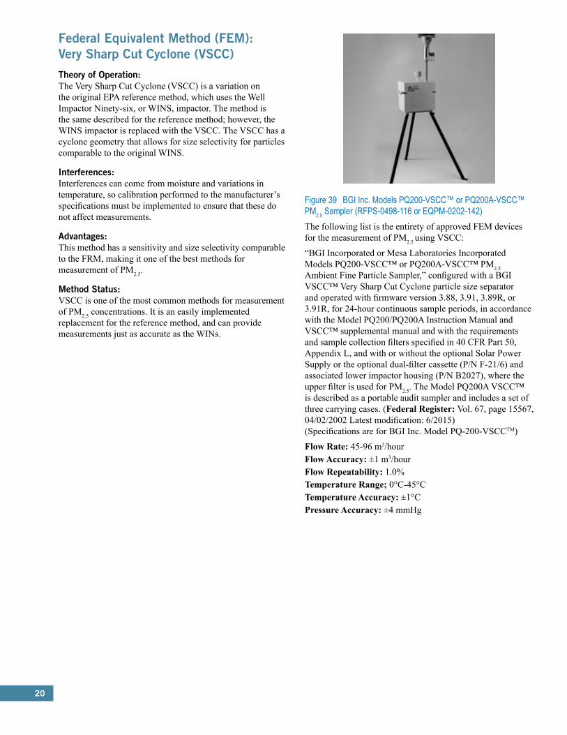
20
Federal Equivalent Method (FEM): Very Sharp Cut Cyclone (VSCC)Theory of Operation:The Very Sharp Cut Cyclone (VSCC) is a variation on the original EPA reference method, which uses the Well Impactor Ninety-six, or WINS, impactor. The method is the same described for the reference method; however, the WINS impactor is replaced with the VSCC. The VSCC has a cyclone geometry that allows for size selectivity for particles comparable to the original WINS.
Interferences:Interferences can come from moisture and variations in temperature, so calibration performed to the manufacturer’s specifications must be implemented to ensure that these do not affect measurements.
Advantages:This method has a sensitivity and size selectivity comparable to the FRM, making it one of the best methods for measurement of PM2.5.
Method Status:VSCC is one of the most common methods for measurement of PM2.5 concentrations. It is an easily implemented replacement for the reference method, and can provide measurements just as accurate as the WINs.
Figure 39 BGI Inc. Models PQ200-VSCC™ or PQ200A-VSCC™ PM2.5 Sampler (RFPS-0498-116 or EQPM-0202-142)The following list is the entirety of approved FEM devices for the measurement of PM2.5 using VSCC:
“BGI Incorporated or Mesa Laboratories Incorporated Models PQ200-VSCC™ or PQ200A-VSCC™ PM2.5 Ambient Fine Particle Sampler,” configured with a BGI VSCC™ Very Sharp Cut Cyclone particle size separator and operated with firmware version 3.88, 3.91, 3.89R, or 3.91R, for 24-hour continuous sample periods, in accordance with the Model PQ200/PQ200A Instruction Manual and VSCC™ supplemental manual and with the requirements and sample collection filters specified in 40 CFR Part 50, Appendix L, and with or without the optional Solar Power Supply or the optional dual-filter cassette (P/N F-21/6) and associated lower impactor housing (P/N B2027), where the upper filter is used for PM2.5. The Model PQ200A VSCC™ is described as a portable audit sampler and includes a set of three carrying cases. (Federal Register: Vol. 67, page 15567, 04/02/2002 Latest modification: 6/2015) (Specifications are for BGI Inc. Model PQ-200-VSCCTM)
Flow Rate: 45-96 m3/hourFlow Accuracy: ±1 m3/hourFlow Repeatability: 1.0%Temperature Range;� 0°C-45°CTemperature Accuracy: ±1°CPressure Accuracy: ±4 mmHg

21
Figure 40 Opsis SM200- Dust Monitor (EQPM-0812-203)
“Opsis SM200- Dust Monitor” configured for PM2.5 with the US EPA PM10 inlet specified in 40 CFR 50 Appendix L, followed by a BGI Inc. Very Sharp Cut Cyclone (VSCC™) particle size separator, operated for a 24-hour continuous sample period at a total actual flow rate of 16.67 L/min. using 47mm PTFE membrane filters, a TS200 temperature stabilizer and software version 1.04.16 or later, in accordance with the Opsis SM200 Dust Monitor Operation and Instruction Guide. (Federal Register: Vol. 77, page 55832, 09/11/2012)
Flow Rate: 8-25 LPMFlow Rate Accuracy: ±2%Beta Ray Source: Carbon 14Temperature Range: 5°C - 35°C
Rupprecht & Patashnick Partisol® Model 2000 PM2.5 FEM Audit Sampler (RFPS-0499-129 or EQPM-0202-144)*“Rupprecht & Patashnick Co., Inc. Partisol® Model 2000 PM2.5 FEM Audit Sampler,” configured with a BGI VSCC™ Very Sharp Cut Cyclone particle size separator, and operated with software (firmware) version 1.2 - 1.202, for 24-hour continuous sample periods at a flow rate of 16.67 liters/minute, in accordance with the Partisol® Model 2000 Operating Manual and VSCC™ supplemental manual and with the requirements and sample collection filters specified in 40 CFR Part 50, Appendix L. (Federal Register: Vol. 67, page 15567, 04/02/2002)
Thermo Electron Model RAAS2.5-100 FEM PM2.5 Ambient Air Sampler (RFPS-0598-119 or EQPM-0804-153)*“Thermo Electron Corporation Model RAAS2.5-100 FEM PM2.5 Ambient Air Sampler,” configured with a BGI VSCC™ Very Sharp Cut Cyclone particle size separator and operated with software version 06.0B.00 configured for “Single 2.5” operation, for 24-hour continuous sample periods at a flow rate of 16.67 liters/minute, in accordance with the Model RAAS2.5-100 FEM Operator’s Manual and VSCC™ supplemental manual, and in accordance with the requirements and sample collection filters specified in 40 CFR Part 50, Appendix L. (Federal Register: Vol. 69, page 47924, 08/06/2004)
Thermo Electron Model RAAS2.5-200 FEM PM2.5 Audit Air Sampler (RFPS-0299-128 or EQPM-0804-154)*“Thermo Electron Corporation Model RAAS2.5-200 FEM PM2.5 Audit Air Sampler,” configured with a BGI VSCC™ Very Sharp Cut Cyclone particle size separator and operated with software version 06.0B.00, for 24-hour continuous sample periods at a flow rate of 16.67 liters/minute, in accordance with the Model RAAS2.5-200 FEM Operator’s Manual and VSCC™ supplemental manual, and in accordance with the requirements and sample collection filters specified in 40 CFR Part 50, Appendix L. (Federal Register: Vol. 69, page 47924, 08/06/2004)
Flow Rate: 14-25 LPMTemperature Range: -30°C - 45°CTemperature Resolution: 0.1°CPressure Range: 600 mmHg-800 mmHgPressure Accuracy: 10 mmHg
*Photo Not Available
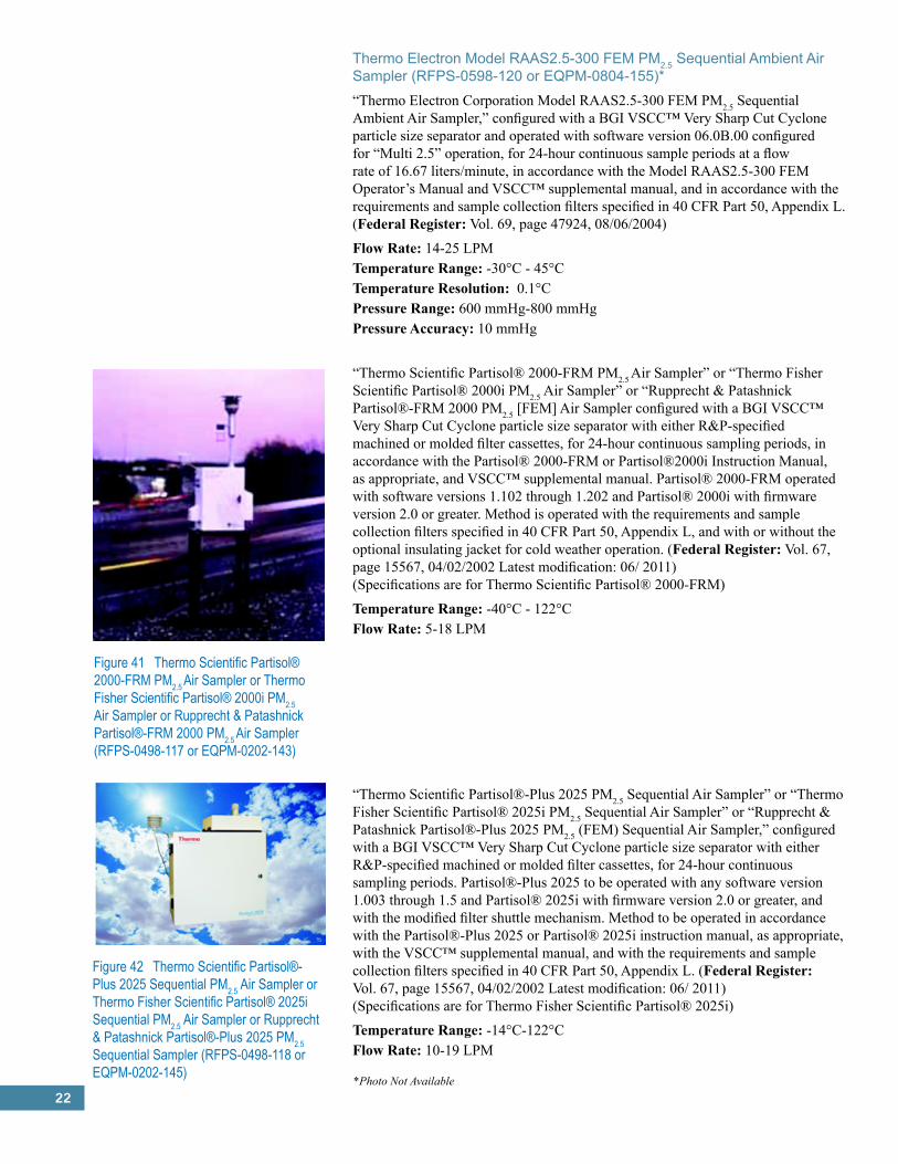
22
Thermo Electron Model RAAS2.5-300 FEM PM2.5 Sequential Ambient Air Sampler (RFPS-0598-120 or EQPM-0804-155)*“Thermo Electron Corporation Model RAAS2.5-300 FEM PM2.5 Sequential Ambient Air Sampler,” configured with a BGI VSCC™ Very Sharp Cut Cyclone particle size separator and operated with software version 06.0B.00 configured for “Multi 2.5” operation, for 24-hour continuous sample periods at a flow rate of 16.67 liters/minute, in accordance with the Model RAAS2.5-300 FEM Operator’s Manual and VSCC™ supplemental manual, and in accordance with the requirements and sample collection filters specified in 40 CFR Part 50, Appendix L. (Federal Register: Vol. 69, page 47924, 08/06/2004)
Flow Rate: 14-25 LPMTemperature Range: -30°C - 45°CTemperature Resolution: 0.1°CPressure Range: 600 mmHg-800 mmHgPressure Accuracy: 10 mmHg
“Thermo Scientific Partisol® 2000-FRM PM2.5 Air Sampler” or “Thermo Fisher Scientific Partisol® 2000i PM2.5 Air Sampler” or “Rupprecht & Patashnick Partisol®-FRM 2000 PM2.5 [FEM] Air Sampler configured with a BGI VSCC™ Very Sharp Cut Cyclone particle size separator with either R&P-specified machined or molded filter cassettes, for 24-hour continuous sampling periods, in accordance with the Partisol® 2000-FRM or Partisol®2000i Instruction Manual, as appropriate, and VSCC™ supplemental manual. Partisol® 2000-FRM operated with software versions 1.102 through 1.202 and Partisol® 2000i with firmware version 2.0 or greater. Method is operated with the requirements and sample collection filters specified in 40 CFR Part 50, Appendix L, and with or without the optional insulating jacket for cold weather operation. (Federal Register: Vol. 67, page 15567, 04/02/2002 Latest modification: 06/ 2011) (Specifications are for Thermo Scientific Partisol® 2000-FRM)
Temperature Range: -40°C - 122°CFlow Rate: 5-18 LPM
Figure 41 Thermo Scientific Partisol® 2000-FRM PM2.5 Air Sampler or Thermo Fisher Scientific Partisol® 2000i PM2.5 Air Sampler or Rupprecht & Patashnick Partisol®-FRM 2000 PM2.5 Air Sampler (RFPS-0498-117 or EQPM-0202-143)
Figure 42 Thermo Scientific Partisol®-Plus 2025 Sequential PM2.5 Air Sampler or Thermo Fisher Scientific Partisol® 2025i Sequential PM2.5 Air Sampler or Rupprecht & Patashnick Partisol®-Plus 2025 PM2.5 Sequential Sampler (RFPS-0498-118 or EQPM-0202-145)
“Thermo Scientific Partisol®-Plus 2025 PM2.5 Sequential Air Sampler” or “Thermo Fisher Scientific Partisol® 2025i PM2.5 Sequential Air Sampler” or “Rupprecht & Patashnick Partisol®-Plus 2025 PM2.5 (FEM) Sequential Air Sampler,” configured with a BGI VSCC™ Very Sharp Cut Cyclone particle size separator with either R&P-specified machined or molded filter cassettes, for 24-hour continuous sampling periods. Partisol®-Plus 2025 to be operated with any software version 1.003 through 1.5 and Partisol® 2025i with firmware version 2.0 or greater, and with the modified filter shuttle mechanism. Method to be operated in accordance with the Partisol®-Plus 2025 or Partisol® 2025i instruction manual, as appropriate, with the VSCC™ supplemental manual, and with the requirements and sample collection filters specified in 40 CFR Part 50, Appendix L. (Federal Register: Vol. 67, page 15567, 04/02/2002 Latest modification: 06/ 2011) (Specifications are for Thermo Fisher Scientific Partisol® 2025i)
Temperature Range: -14°C-122°CFlow Rate: 10-19 LPM
*Photo Not Available
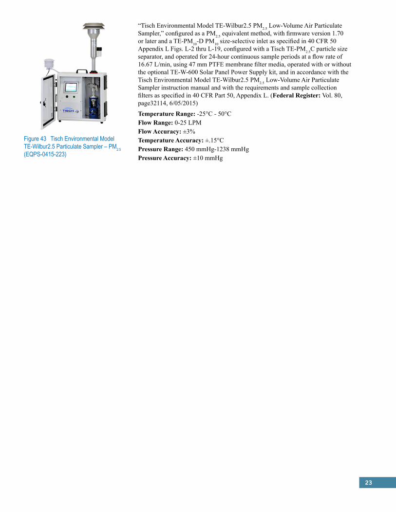
23
Figure 43 Tisch Environmental Model TE-Wilbur2.5 Particulate Sampler – PM2.5 (EQPS-0415-223)
“Tisch Environmental Model TE-Wilbur2.5 PM2.5 Low-Volume Air Particulate Sampler,” configured as a PM2.5 equivalent method, with firmware version 1.70 or later and a TE-PM10-D PM10 size-selective inlet as specified in 40 CFR 50 Appendix L Figs. L-2 thru L-19, configured with a Tisch TE-PM2.5C particle size separator, and operated for 24-hour continuous sample periods at a flow rate of 16.67 L/min, using 47 mm PTFE membrane filter media, operated with or without the optional TE-W-600 Solar Panel Power Supply kit, and in accordance with the Tisch Environmental Model TE-Wilbur2.5 PM2.5 Low-Volume Air Particulate Sampler instruction manual and with the requirements and sample collection filters as specified in 40 CFR Part 50, Appendix L. (Federal Register: Vol. 80, page32114, 6/05/2015)
Temperature Range: -25°C - 50°CFlow Range: 0-25 LPMFlow Accuracy: ±3%Temperature Accuracy: ±.15°CPressure Range: 450 mmHg-1238 mmHgPressure Accuracy: ±10 mmHg
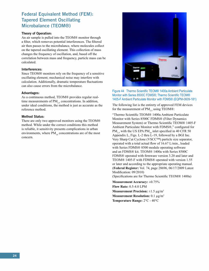
24
Federal Equivalent Method (FEM): Tapered Element Oscillating Microbalance (TEOM®)Theory of Operation:An air sample is pulled into the TEOM® monitor through a filter, which removes potential interferences. The filtered air then passes to the microbalance, where molecules collect on the tapered oscillating element. This collection of mass changes the frequency of oscillation, and, based off the correlation between mass and frequency, particle mass can be calculated.
Interferences:Since TEOM® monitors rely on the frequency of a sensitive oscillating element; mechanical noise may interfere with calculation. Additionally, dramatic temperature fluctuations can also cause errors from the microbalance.
Advantages:As a continuous method, TEOM® provides regular real-time measurements of PM2.5 concentrations. In addition, under ideal conditions, the method is just as accurate as the reference method.
Method Status:There are only two approved monitors using the TEOM® method. While under the correct conditions this method is reliable, it sensitivity presents complications in urban environments, where PM10 concentrations are of the most concern.
Figure 44 Thermo Scientific TEOM® 1400a Ambient Particulate Monitor with Series 8500C FDMS®; Thermo Scientific TEOM® 1405-F Ambient Particulate Monitor with FDMS® (EQPM-0609-181) The following list is the entirety of approved FEM devices for the measurement of PM2.5 using TEOM®:
“Thermo Scientific TEOM® 1400a Ambient Particulate Monitor with Series 8500C FDMS® (Filter Dynamics Measurement System) or Thermo Scientific TEOM® 1405-F Ambient Particulate Monitor with FDMS®,” configured for PM2.5 with the US EPA PM10 inlet specified in 40 CFR 50 Appendix L, Figs. L-2 thru L-19, followed by a BGI Inc. Very Sharp Cut Cyclone (VSCC™) particle size separator, operated with a total actual flow of 16.67 L/min., loaded with Series FDMS® 8500 module operating software and an FDMS® kit. TEOM® 1400a with Series 8500C FDMS® operated with firmware version 3.20 and later and TEOM® 1405-F with FDMS® operated with version 1.55 or later and according to the appropriate operating manual. (Federal Register: Vol. 74, page 28696, 06/17/2009 Latest Modification: 09/2010) (Specifications are for Thermo Scientific TEOM® 1400a)
Measurement Accuracy: ±0.75%Flow Rate: 0.5-4.0 LPMMeasurement Precision: ±1.5 µg/m3
Measurement Resolution: 0.1 µg/m3
Temperature Range: 2°C - 40°C
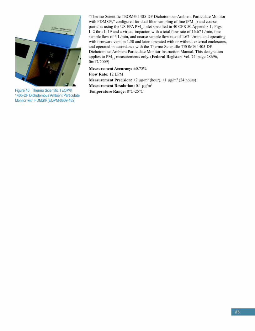
25
Figure 45 Thermo Scientific TEOM® 1405-DF Dichotomous Ambient Particulate Monitor with FDMS® (EQPM-0609-182)
“Thermo Scientific TEOM® 1405-DF Dichotomous Ambient Particulate Monitor with FDMS®,” configured for dual filter sampling of fine (PM2.5) and coarse particles using the US EPA PM10 inlet specified in 40 CFR 50 Appendix L, Figs. L-2 thru L-19 and a virtual impactor, with a total flow rate of 16.67 L/min, fine sample flow of 3 L/min, and coarse sample flow rate of 1.67 L/min, and operating with firmware version 1.50 and later, operated with or without external enclosures, and operated in accordance with the Thermo Scientific TEOM® 1405-DF Dichotomous Ambient Particulate Monitor Instruction Manual. This designation applies to PM2.5 measurements only. (Federal Register: Vol. 74, page 28696, 06/17/2009)
Measurement Accuracy: ±0.75%Flow Rate: 12 LPMMeasurement Precision: ±2 µg/m3 (hour), ±1 µg/m3 (24 hours)Measurement Resolution: 0.1 µg/m3
Temperature Range: 8°C-25°C
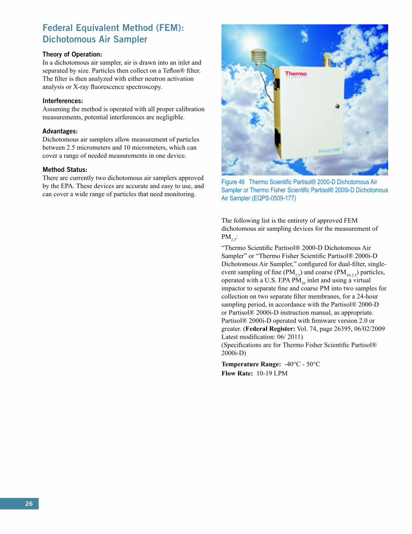
26
Federal Equivalent Method (FEM): Dichotomous Air SamplerTheory of Operation:In a dichotomous air sampler, air is drawn into an inlet and separated by size. Particles then collect on a Teflon® filter. The filter is then analyzed with either neutron activation analysis or X-ray fluorescence spectroscopy.
Interferences:Assuming the method is operated with all proper calibration measurements, potential interferences are negligible.
Advantages:Dichotomous air samplers allow measurement of particles between 2.5 micrometers and 10 micrometers, which can cover a range of needed measurements in one device.
Method Status:There are currently two dichotomous air samplers approved by the EPA. These devices are accurate and easy to use, and can cover a wide range of particles that need monitoring.
Figure 46 Thermo Scientific Partisol® 2000-D Dichotomous Air Sampler or Thermo Fisher Scientific Partisol® 2000i-D Dichotomous Air Sampler (EQPS-0509-177)
The following list is the entirety of approved FEM dichotomous air sampling devices for the measurement of PM2.5:
“Thermo Scientific Partisol® 2000-D Dichotomous Air Sampler” or “Thermo Fisher Scientific Partisol® 2000i-D Dichotomous Air Sampler,” configured for dual-filter, single-event sampling of fine (PM2.5) and coarse (PM10-2.5) particles, operated with a U.S. EPA PM10 inlet and using a virtual impactor to separate fine and coarse PM into two samples for collection on two separate filter membranes, for a 24-hour sampling period, in accordance with the Partisol® 2000-D or Partisol® 2000i-D instruction manual, as appropriate. Partisol® 2000i-D operated with firmware version 2.0 or greater. (Federal Register: Vol. 74, page 26395, 06/02/2009 Latest modification: 06/ 2011) (Specifications are for Thermo Fisher Scientific Partisol® 2000i-D)
Temperature Range: -40°C - 50°CFlow Rate: 10-19 LPM
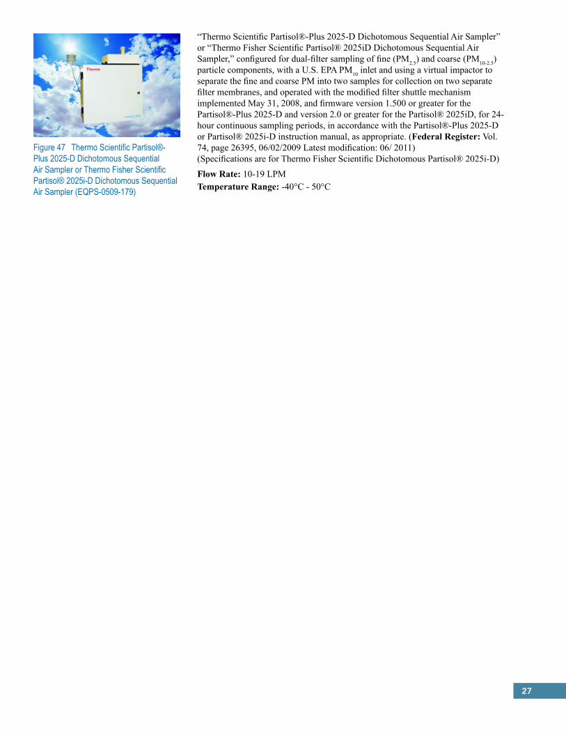
27
Figure 47 Thermo Scientific Partisol®-Plus 2025-D Dichotomous Sequential Air Sampler or Thermo Fisher Scientific Partisol® 2025i-D Dichotomous Sequential Air Sampler (EQPS-0509-179)
“Thermo Scientific Partisol®-Plus 2025-D Dichotomous Sequential Air Sampler” or “Thermo Fisher Scientific Partisol® 2025iD Dichotomous Sequential Air Sampler,” configured for dual-filter sampling of fine (PM2.5) and coarse (PM10-2.5) particle components, with a U.S. EPA PM10 inlet and using a virtual impactor to separate the fine and coarse PM into two samples for collection on two separate filter membranes, and operated with the modified filter shuttle mechanism implemented May 31, 2008, and firmware version 1.500 or greater for the Partisol®-Plus 2025-D and version 2.0 or greater for the Partisol® 2025iD, for 24-hour continuous sampling periods, in accordance with the Partisol®-Plus 2025-D or Partisol® 2025i-D instruction manual, as appropriate. (Federal Register: Vol. 74, page 26395, 06/02/2009 Latest modification: 06/ 2011) (Specifications are for Thermo Fisher Scientific Dichotomous Partisol® 2025i-D)
Flow Rate: 10-19 LPMTemperature Range: -40°C - 50°C
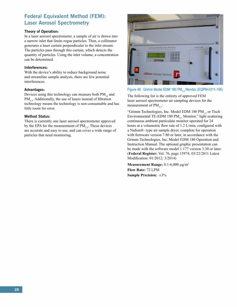
28
Federal Equivalent Method (FEM): Laser Aerosol SpectrometryTheory of Operation:In a laser aerosol spectrometer, a sample of air is drawn into a narrow inlet that limits rogue particles. Then, a collimator generates a laser curtain perpendicular to the inlet stream. The particles pass through this curtain, which detects the quantity of particles. Using the inlet volume, a concentration can be determined.
Interferences:With the device’s ability to reduce background noise and streamline sample analysis, there are few potential interferences.
Advantages:Devices using this technology can measure both PM10 and PM2.5. Additionally, the use of lasers instead of filtration technology means the technology is non-consumable and has little room for error.
Method Status:There is currently one laser aerosol spectrometer approved by the EPA for the measurement of PM2.5. These devices are accurate and easy to use, and can cover a wide range of particles that need monitoring.
Figure 48 Grimm Model EDM 180 PM2.5 Monitor (EQPM-0311-195)The following list is the entirety of approved FEM laser aerosol spectrometer air sampling devices for the measurement of PM2.5:
“Grimm Technologies, Inc. Model EDM 180 PM2.5 or Tisch Environmental TE-EDM 180 PM2.5 Monitor,” light scattering continuous ambient particulate monitor operated for 24 hours at a volumetric flow rate of 1.2 L/min, configured with a Nafion®- type air sample dryer, complete for operation with firmware version 7.80 or later, in accordance with the Grimm Technologies, Inc. Model EDM 180 Operation and Instruction Manual. The optional graphic presentation can be made with the software model 1.177 version 3.30 or later. (Federal Register: Vol. 76, page 15974, 03/22/2011 Latest Modification: 01/2012; 3/2014)
Measurement Range: 0.1-6,000 µg/m3
Flow Rate: 72 LPMSample Precision: ±3%
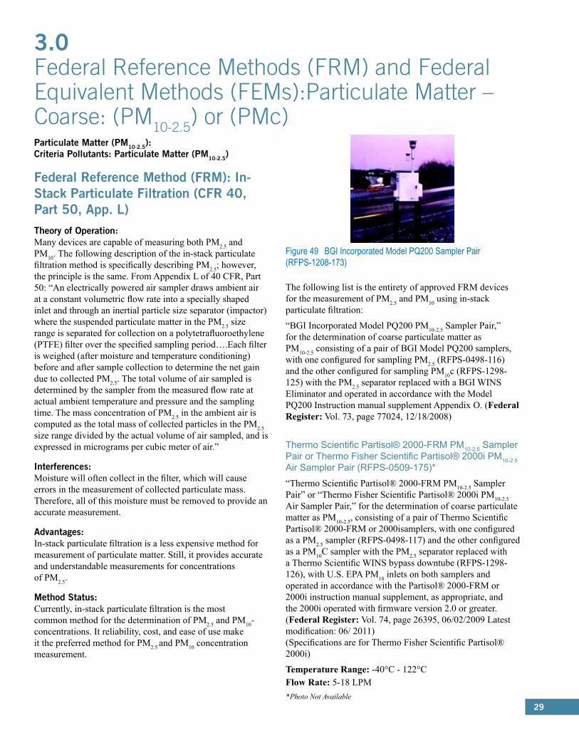
29
Particulate Matter (PM10-2.5): Criteria Pollutants: Particulate Matter (PM10-2.5)
Federal Reference Method (FRM): In-Stack Particulate Filtration (CFR 40, Part 50, App. L)Theory of Operation:Many devices are capable of measuring both PM2.5 and PM10. The following description of the in-stack particulate filtration method is specifically describing PM2.5; however, the principle is the same. From Appendix L of 40 CFR, Part 50: “An electrically powered air sampler draws ambient air at a constant volumetric flow rate into a specially shaped inlet and through an inertial particle size separator (impactor) where the suspended particulate matter in the PM2.5 size range is separated for collection on a polytetrafluoroethylene (PTFE) filter over the specified sampling period….Each filter is weighed (after moisture and temperature conditioning) before and after sample collection to determine the net gain due to collected PM2.5. The total volume of air sampled is determined by the sampler from the measured flow rate at actual ambient temperature and pressure and the sampling time. The mass concentration of PM2.5 in the ambient air is computed as the total mass of collected particles in the PM2.5 size range divided by the actual volume of air sampled, and is expressed in micrograms per cubic meter of air.”
Interferences:Moisture will often collect in the filter, which will cause errors in the measurement of collected particulate mass. Therefore, all of this moisture must be removed to provide an accurate measurement.
Advantages:In-stack particulate filtration is a less expensive method for measurement of particulate matter. Still, it provides accurate and understandable measurements for concentrations of PM2.5.
Method Status:Currently, in-stack particulate filtration is the most common method for the determination of PM2.5 and PM10- concentrations. It reliability, cost, and ease of use make it the preferred method for PM2.5 and PM10 concentration measurement.
3.0 Federal Reference Methods (FRM) and Federal Equivalent Methods (FEMs):Particulate Matter – Coarse: (PM10-2.5) or (PMc)
Figure 49 BGI Incorporated Model PQ200 Sampler Pair (RFPS-1208-173)
The following list is the entirety of approved FRM devices for the measurement of PM2.5 and PM10 using in-stack particulate filtration:
“BGI Incorporated Model PQ200 PM10-2.5 Sampler Pair,” for the determination of coarse particulate matter as PM10-2.5 consisting of a pair of BGI Model PQ200 samplers, with one configured for sampling PM2.5 (RFPS-0498-116) and the other configured for sampling PM10c (RFPS-1298-125) with the PM2.5 separator replaced with a BGI WINS Eliminator and operated in accordance with the Model PQ200 Instruction manual supplement Appendix O. (Federal Register: Vol. 73, page 77024, 12/18/2008)
Thermo Scientific Partisol® 2000-FRM PM10-2.5 Sampler Pair or Thermo Fisher Scientific Partisol® 2000i PM10-2.5 Air Sampler Pair (RFPS-0509-175)*“Thermo Scientific Partisol® 2000-FRM PM10-2.5 Sampler Pair” or “Thermo Fisher Scientific Partisol® 2000i PM10-2.5 Air Sampler Pair,” for the determination of coarse particulate matter as PM10-2.5, consisting of a pair of Thermo Scientific Partisol® 2000-FRM or 2000isamplers, with one configured as a PM2.5 sampler (RFPS-0498-117) and the other configured as a PM10C sampler with the PM2.5 separator replaced with a Thermo Scientific WINS bypass downtube (RFPS-1298-126), with U.S. EPA PM10 inlets on both samplers and operated in accordance with the Partisol® 2000-FRM or 2000i instruction manual supplement, as appropriate, and the 2000i operated with firmware version 2.0 or greater. (Federal Register: Vol. 74, page 26395, 06/02/2009 Latest modification: 06/ 2011) (Specifications are for Thermo Fisher Scientific Partisol® 2000i)
Temperature Range: -40°C - 122°CFlow Rate: 5-18 LPM*Photo Not Available

30
Figure 50 Thermo Scientific Partisol®-Plus 2025 Sequential PM10-2.5 Air Sampler Pair or Thermo Fisher Scientific Partisol® 2025i Sequential PM10-2.5 Air Sampler Pair (RFPS-0509-176)
“Thermo Scientific Partisol®-Plus 2025 Sequential PM10-2.5 Air Sampler Pair” or “Thermo Fisher Scientific Partisol® 2025i Sequential PM10-2.5 Air Sampler Pair,” for the determination of coarse particulate matter as PM10-2.5, consisting of a pair of Thermo Scientific Partisol®-Plus 2025 sequential samplers or a pair of Thermo Fisher Scientific Partisol® 2025i sequential samplers, with one configured as a PM2.5 sampler (RFPS-0498-118) and the other configured as a PM10c sampler with the PM2.5 separator replaced with a Thermo Scientific Partisol® 2025 downtube (RFPS-1298-127). Partisol®-Plus 2025 to be operated with any software version 1.003 through 1.5 and Partisol® 2025i with firmware version 2.0 or greater, with the modified filter shuttle mechanism. Method to be operated in accordance with the Partisol®-Plus 2025 or Partisol® 2025i instruction manual supplement, as appropriate. (Federal Register: Vol. 74, page 26395, 06/02/2009 Latest modification: 06/ 2011) (Specifications are for Thermo Fisher Scientific Partisol® 2025i)
Temperature Range: -14°C - 122°CFlow Rate: 10-19 LPM
Figure 51 Tisch Environmental Model TE-Wilbur Low-Volume Air Particulate Sampler Pair (RFPS-1014-220)
“Tisch Environmental Model TE-Wilbur Low-Volume Air Particulate Sampler Pair” for the determination of coarse particulate matter as PM10-2.5, consisting of a pair of Tisch Environmental Model TE-Wilbur samplers, with one being the TE-Wilbur2.5 PM2.5 sampler (RFPS-1014-219) and the other being a TE-Wilbur10 PM10 sampler (RFPS-0714-216), and operated in accordance with the associated TE-Wilbur instruction manual. This designation applies to PM10-2.5 measurements only. (Federal Register: Vol. 79, page 65392, 11/04/2014)
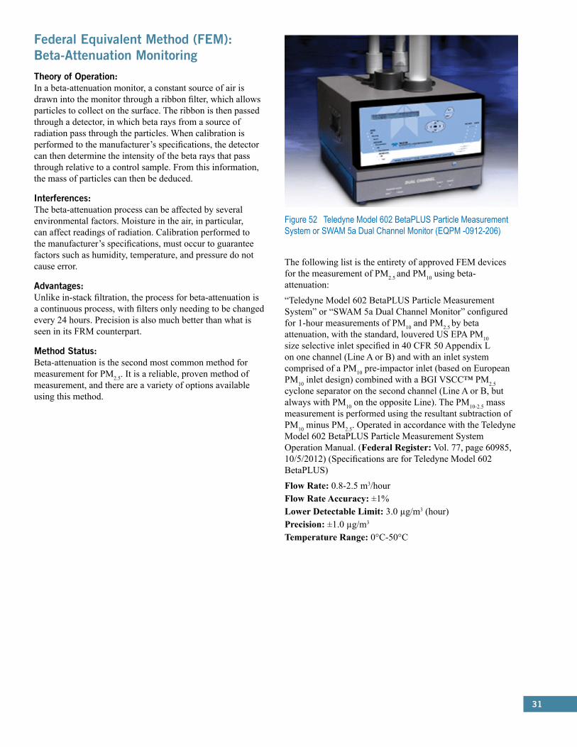
31
Federal Equivalent Method (FEM): Beta-Attenuation MonitoringTheory of Operation:In a beta-attenuation monitor, a constant source of air is drawn into the monitor through a ribbon filter, which allows particles to collect on the surface. The ribbon is then passed through a detector, in which beta rays from a source of radiation pass through the particles. When calibration is performed to the manufacturer’s specifications, the detector can then determine the intensity of the beta rays that pass through relative to a control sample. From this information, the mass of particles can then be deduced.
Interferences:The beta-attenuation process can be affected by several environmental factors. Moisture in the air, in particular, can affect readings of radiation. Calibration performed to the manufacturer’s specifications, must occur to guarantee factors such as humidity, temperature, and pressure do not cause error.
Advantages:Unlike in-stack filtration, the process for beta-attenuation is a continuous process, with filters only needing to be changed every 24 hours. Precision is also much better than what is seen in its FRM counterpart.
Method Status:Beta-attenuation is the second most common method for measurement for PM2.5. It is a reliable, proven method of measurement, and there are a variety of options available using this method.
Figure 52 Teledyne Model 602 BetaPLUS Particle Measurement System or SWAM 5a Dual Channel Monitor (EQPM -0912-206)
The following list is the entirety of approved FEM devices for the measurement of PM2.5 and PM10 using beta-attenuation:
“Teledyne Model 602 BetaPLUS Particle Measurement System” or “SWAM 5a Dual Channel Monitor” configured for 1-hour measurements of PM10 and PM2.5 by beta attenuation, with the standard, louvered US EPA PM10 size selective inlet specified in 40 CFR 50 Appendix L on one channel (Line A or B) and with an inlet system comprised of a PM10 pre-impactor inlet (based on European PM10 inlet design) combined with a BGI VSCC™ PM2.5 cyclone separator on the second channel (Line A or B, but always with PM10 on the opposite Line). The PM10-2.5 mass measurement is performed using the resultant subtraction of PM10 minus PM2.5. Operated in accordance with the Teledyne Model 602 BetaPLUS Particle Measurement System Operation Manual. (Federal Register: Vol. 77, page 60985, 10/5/2012) (Specifications are for Teledyne Model 602 BetaPLUS)
Flow Rate: 0.8-2.5 m3/hourFlow Rate Accuracy: ±1%Lower Detectable Limit: 3.0 µg/m3 (hour)Precision: ±1.0 µg/m3
Temperature Range: 0°C-50°C

32
Federal Equivalent Method (FEM): Tapered Element Oscillating Microbalance (TEOM®)Theory of Operation:An air sample is pulled into the TEOM® monitor through a filter, which removes potential interferences. The filtered air then passes to the microbalance, where molecules collect on the tapered oscillating element. This collection of mass changes the frequency of oscillation, and, based off the correlation between mass and frequency, particle mass can be calculated.
Interferences:Since TEOM® monitors rely on the frequency of a sensitive oscillating element; mechanical noise may interfere with calculation. Additionally, dramatic temperature fluctuations can also cause errors from the microbalance.
Advantages:As a continuous method, TEOM® provides regular real-time measurements of PM10 concentrations. In addition, under ideal conditions, the method is just as accurate as the reference method.
Method Status:There are only two approved monitors using the TEOM® method. While under the correct conditions this method is reliable, it sensitivity presents complications in urban environments, where PM10 concentrations are of the most concern.
Figure 53 Thermo Scientific TEOM® 1405-DF Dichotomous Ambient Particulate Monitor with FDMS® (EQPM-1013-207)
The following list is the entirety of approved FEM devices for the measurement of PM2.5 and PM10 using TEOM®:
“Thermo Scientific TEOM® 1405-DF Dichotomous Ambient Particulate Monitor with FDMS®,” configured for dual filter sampling of fine (PM2.5) and coarse particles using the US EPA PM10 inlet specified in 40 CFR 50 Appendix L, Figs. L-2 thru L-19 and a virtual impactor, with a total flow rate of 16.67 L/min, fine sample flow of 3 L/min, and coarse sample flow rate of 1.67 L/min, and operating with firmware version 1.70 and later, operated with or without external enclosures, and operated in accordance with the Thermo Scientific TEOM® 1405-DF Dichotomous Ambient Particulate Monitor Instruction Manual. This designation applies to PM10-2.5 measurements only. (Federal Register: Vol. 78, page 67360, 11/12/2013)
Measurement Accuracy:: ±0.75%Flow Rate:: 12 LPMMeasurement Precision:: ±2 µg/m3 (hour), ±1 µg/m3 (24 hours)Measurement Resolution:: 0.1 µg/m3
Temperature Range:: 8°C - 25°C
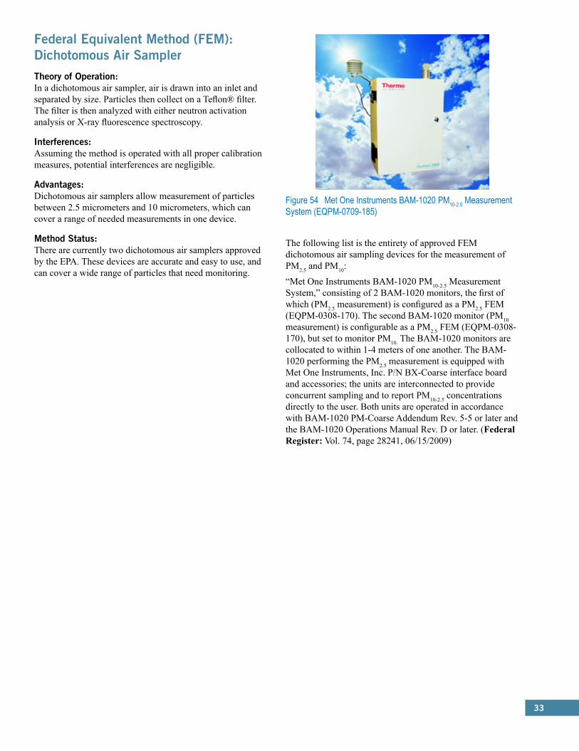
33
Federal Equivalent Method (FEM): Dichotomous Air SamplerTheory of Operation:In a dichotomous air sampler, air is drawn into an inlet and separated by size. Particles then collect on a Teflon® filter. The filter is then analyzed with either neutron activation analysis or X-ray fluorescence spectroscopy.
Interferences:Assuming the method is operated with all proper calibration measures, potential interferences are negligible.
Advantages:Dichotomous air samplers allow measurement of particles between 2.5 micrometers and 10 micrometers, which can cover a range of needed measurements in one device.
Method Status:There are currently two dichotomous air samplers approved by the EPA. These devices are accurate and easy to use, and can cover a wide range of particles that need monitoring.
Figure 54 Met One Instruments BAM-1020 PM10-2.5 Measurement System (EQPM-0709-185)
The following list is the entirety of approved FEM dichotomous air sampling devices for the measurement of PM2.5 and PM10:
“Met One Instruments BAM-1020 PM10-2.5 Measurement System,” consisting of 2 BAM-1020 monitors, the first of which (PM2.5 measurement) is configured as a PM2.5 FEM (EQPM-0308-170). The second BAM-1020 monitor (PM10 measurement) is configurable as a PM2.5 FEM (EQPM-0308-170), but set to monitor PM10. The BAM-1020 monitors are collocated to within 1-4 meters of one another. The BAM-1020 performing the PM2.5 measurement is equipped with Met One Instruments, Inc. P/N BX-Coarse interface board and accessories; the units are interconnected to provide concurrent sampling and to report PM10-2.5 concentrations directly to the user. Both units are operated in accordance with BAM-1020 PM-Coarse Addendum Rev. 5-5 or later and the BAM-1020 Operations Manual Rev. D or later. (Federal Register: Vol. 74, page 28241, 06/15/2009)
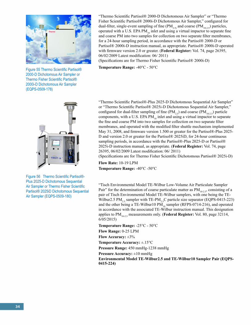
34
Figure 55 Thermo Scientific Partisol® 2000-D Dichotomous Air Sampler or Thermo Fisher Scientific Partisol® 2000i-D Dichotomous Air Sampler (EQPS-0509-178)
“Thermo Scientific Partisol® 2000-D Dichotomous Air Sampler” or “Thermo Fisher Scientific Partisol® 2000i-D Dichotomous Air Sampler,” configured for dual-filter, single-event sampling of fine (PM2.5) and coarse (PM10-2.5) particles, operated with a U.S. EPA PM10 inlet and using a virtual impactor to separate fine and coarse PM into two samples for collection on two separate filter membranes, for a 24-hour sampling period, in accordance with the Partisol® 2000-D or Partisol® 2000i-D instruction manual, as appropriate. Partisol® 2000i-D operated with firmware version 2.0 or greater. (Federal Register: Vol. 74, page 26395, 06/02/2009 Latest modification: 06/ 2011) (Specifications are for Thermo Fisher Scientific Partisol® 2000i-D)
Temperature Range: -40°C - 50°C
Figure 56 Thermo Scientific Partisol®-Plus 2025-D Dichotomous Sequential Air Sampler or Thermo Fisher Scientific Partisol® 2025iD Dichotomous Sequential Air Sampler (EQPS-0509-180)
“Thermo Scientific Partisol®-Plus 2025-D Dichotomous Sequential Air Sampler” or “Thermo Scientific Partisol® 2025i-D Dichotomous Sequential Air Sampler,” configured for dual-filter sampling of fine (PM2.5) and coarse (PM10-2.5) particle components, with a U.S. EPA PM10 inlet and using a virtual impactor to separate the fine and coarse PM into two samples for collection on two separate filter membranes, and operated with the modified filter shuttle mechanism implemented May 31, 2008, and firmware version 1.500 or greater for the Partisol®-Plus 2025-D and version 2.0 or greater for the Partisol® 2025iD, for 24-hour continuous sampling periods, in accordance with the Partisol®-Plus 2025-D or Partisol® 2025i-D instruction manual, as appropriate. (Federal Register: Vol. 74, page 26395, 06/02/2009 Latest modification: 06/ 2011) (Specifications are for Thermo Fisher Scientific Dichotomous Partisol® 2025i-D)
Flow Rate: 10-19 LPMTemperature Range: -40°C -50°C
“Tisch Environmental Model TE-Wilbur Low-Volume Air Particulate Sampler Pair” for the determination of coarse particulate matter as PM10-2.5, consisting of a pair of Tisch Environmental Model TE-Wilbur samplers, with one being the TE-Wilbur2.5 PM2.5 sampler with TE-PM2.5C particle size separator (EQPS-0415-223) and the other being a TE-Wilbur10 PM10 sampler (RFPS-0714-216), and operated in accordance with the associated TE-Wilbur instruction manual. This designation applies to PM10-2.5 measurements only. (Federal Register: Vol. 80, page 32114, 6/05/2015)Temperature Range: -25°C - 50°CFlow Range: 0-25 LPMFlow Accuracy: ±3%Temperature Accuracy: ±.15°CPressure Range: 450 mmHg-1238 mmHgPressure Accuracy: ±10 mmHgEnvironmental Model TE-Wilbur2.5 and TE-Wilbur10 Sampler Pair (EQPS-0415-224)
35
4.0 Federal Reference Methods (FRM) and Federal Equivalent Methods (FEMs):Sulfur Dioxide (SO2)
Criteria Pollutant: Sulfur Dioxide (SO2)
Federal Reference Method (FRM): Pararosaniline Method (CFR 40, Part 50, App. A)Theory of Operation:The pararosaniline method relies on the method of measurement described in Appendix A of 40 CFR, Part 50: “A measured volume of air is bubbled through a solution of 0.04 M potassium tetrachloromercurate (TCM). The SO2 present in the air stream reacts with the TCM solution to form a stable monochlorosulfonatomercurate complex. Once formed, this complex resists air oxidation and is stable in the presence of strong oxidants such as ozone and oxides of nitrogen. During subsequent analysis, the complex is reacted with acid-bleached pararosaniline dye and formaldehyde to form an intensely colored pararosaniline methyl sulfonic acid. The optical density of this species is determined spectrophotometrically at 548 nm and is directly related to the amount of SO2 collected. The total volume of air sampled, corrected to EPA reference conditions (25 C, 760 mmHg [101 kPa]), is determined from the measured flow rate and the sampling time. The concentration of SO2 in the ambient air is computed and expressed in micrograms per standard cubic meter.”
Interferences:Potential interferences such as nitrogen oxides and heavy metals are eliminated by the addition of sulfamic acid and EDTA/phosphoric acid, respectively. Also, ozone interference is prevented by the time delay.
Advantages;When calibration is performed to the manufacturer’s specifications, the Pararosaniline Method produces very accurate results for the measurement of SO2. Additionally, it is a relatively inexpensive and simple procedure, making it a preferred method in certain parts of the world.
Method Status:While the Pararosaniline Method is the current reference method for SO2 measurement, it is not widely used because it is a ‘wet chemistry’ method requiring an extensive and expensive analytical chemistry procedure using skilled personnel to analyze the results. Most SO2 monitoring networks are moving to the ultraviolet fluorescence (UVF) Federal Equivalent Method (FEM), which is a gas-reaction method that does not require ‘wet chemistry’ procedures.
Federal Equivalent Method (FEM): U.V. FluorescenceTheory of Operation:Sulfur dioxide releases a characteristic fluorescence when it is irradiated by ultraviolet light of 190-230 nm. The molecule absorbs this region of light, while most other pollutants in air do not. Therefore, in devices using U.V. fluorescence, a beam of radiation is passed through a sample. The decay radiation is passed through a filter and photomultiplier tube, which allows a concentration to be measured.
Interferences:Water vapor and oxygen can interfere with this characteristic fluorescence of sulfur dioxide at certain wavelengths. Water vapor must be removed by a dryer or by selecting particular wavelengths to limit error. Diluting an air sample with nitrogen can reduce the oxygen concentration, reducing error in this regard, as well.
Advantages:U.V. Fluorescence is one of the most sensitive methods for measuring concentrations. The method is capable of measuring very particular samples, and with the help of additional U.V. lasers, any interferences or potential overlapping can be eliminated.
Method Status:U.V. Fluorescence is the most widely used method for determination of SO2 concentrations. Many of the earliest devices depended on this method, and it is still widely used today. Its cost effectiveness and ease of use make U.V. Fluorescence one of the best processes for accurate measurement.
The following list is the entirety of approved FEM devices for the measurement of SO2 using U.V. Fluorescence:
Advanced Pollution Instrumentation, Inc. Model 100 SO2 Analyzer (EQSA-0990-077)*“Advanced Pollution Instrumentation, Inc. Model 100 Fluorescent SO2 Analyzer,” operated on the 0-0.1 ppm , the 0-0.2 ppm , the 0-0.5 ppm, or the 0-1.0 ppm range with a 5-micron TFE filter element installed in the rear-panel filter assembly, either a user- or vendor-supplied vacuum pump

36
capable of providing 20 inches of mercury vacuum at 2.5 L/min, with or without any of the following options: Internal Zero/Span; Pump Pack; Rack Mount With Slides; RS-232 Interface; Status Output; TFE Zero/Span Valves; Zero Air Scrubber; Dual Range.2 (Federal Register: Vol. 55, page 38149, 09/17/1990)
Beckman Model 953 Fluorescent Ambient SO2 Analyzer (EQSA-0678-029)*“Beckman Model 953 Fluorescent Ambient SO2 Analyzer,” operated on a range of either 0-0.5ppm or 0-1.0 ppm, with a time constant setting of 2, 2.5, or 3 minutes, a 5 to 10 micron membrane filter element installed in the rear-panel filter assembly, with or without any of the following options: Remote Operation Kit, Catalog No. 641984; Digital Panel Meter, Catalog No. 641710; Rack Mount Kit, Catalog No. 641709; Panel Mount Kit, Catalog No. 641708. (Federal Register: Vol. 43, page 35995, 08/14/1978)
“Dasibi Model 4108 U.V. Fluorescence SO2 Analyzer,” operated with a range of 0-100 ppb , 0-200 ppb , 0-500 ppb, or 0-1000 ppb, with a Teflon-coated particulate filter and continuous hydrocarbon removal system, with or without any of the following options: Rack Mounting Brackets and Slides; RS-232-C Interface; Temperature Correction. (Federal Register: Vol. 51, page 32244, 09/10/1986)
“DKK-TOA Corporation Model GFS-32 Ambient Air SO2 Ultraviolet Fluorescent Analyzer,” operated within the 0.000 to 0.500 ppm range in the temperature range of 20°C to 30°C. (Federal Register: Vol. 62, page 44007, 08/18/1997)
“DKK-TOA Corporation Models GFS-112E and GFS-112E-1 U.V. Fluorescence SO2 Analyzer,” operated at any temperature ranging from 15ºC to 35ºC, on any of the following measurement ranges: 0-0.05 ppm, 0-0.100 ppm, 0-0.200 ppm, 0-0.5 ppm, or 0-1.000 ppm, and with or without the optional internal zero air supply and permeation tube oven. (Federal Register: Vol. 65, page 2610, 01/18/2000)
“DKK-TOA Corporation Model GFS-312E Ambient SO2 Analyzer,” operated at any environmental temperature in the range of 20oC to 30oC on any of the following measurement ranges: 0-0.1 ppm, 0-0.2 ppm and 0-0.5 ppm. (Federal Register: Vol. 72, page 63176, 11/08/2007)
Lower Detectable Limit: 0.2 ppbZero Drift: ±0.5 ppb (24 hours)Span Drift: ±1% (24 hours)Temperature Range: 0°C-40°CFigure 59. Ecotech Serinus 50 Sulfur Dioxide Analyzer or Opsis AB OPS50 Sulfur Dioxide Analyzer or Teledyne Analytical Instruments 6400E Sulfur Dioxide Analyzer or Tisch Environmental TE 2.0 Sulfur Dioxide Analyzer (EQSA-0809-188)“Ecotech Serinus 50 Sulfur Dioxide Analyzer” or “Opsis AB OPS50 Sulfur Dioxide Analyzer” or “Teledyne Analytical Instruments 6400E Sulfur Dioxide Analyzer” or “Tisch Environmental TE 2.0 Sulfur Dioxide Analyzer,” operated in the range of 0–0.5 ppm, with a five-micron Teflon® filter element installed, and with the following selected: Background-Enabled, Control Loop-Enabled, Diagnostic Mode-Operate, Pres/Temp/Flow Compensation-Enabled, Span Compensation-Disabled, with concentration automatically corrected for temperature and pressure
Figure 57 Dasibi Model 4108 U.V. Fluorescence SO2 Analyzer (EQSA-1086-061)
Figure 58 DKK-TOA Corp. Model GFS-312E Ambient SO2 Analyzer (EQSA-1107-168)
*Photo Not Available

37
changes, and operated according to the Serinus 50 Sulfur Dioxide Analyzer User Manual or the Opsis OPS50 Sulfur Dioxide Analyzer User Manual or the Teledyne Analytical Instruments 6400E Sulfur Dioxide Analyzer Instruction Manual or the Tisch
Environmental TE 2.0 Sulfur Dioxide Analyzer Instruction Manual, as appropriate. (Federal Register: Vol. 74, page 38184, 07/31/2009 Latest Modifications: 05/2010, 05/2011, 05/2012, 8/2014) (Specifications are for Ecotech Serinus 50)
Measurement Range: 0-20 ppmLower Detectable Limit: Greater of <0.15 ppb or 0.2% of measurementLinearity: <1% of full scaleZero Drift: <0.5 ppb (24 hours, 7 days)Span Drift: <0.5% of readingTemperature Range: 0°C - 40°C
“Environnement S.A Model AF21M Sulfur Dioxide Analyzer,” operated on a range of 0-0.5 ppm with a response time coefficient setting of 01, a Teflon filter installed in the rear-panel filter assembly, and with or without any of the following options: Rack Mount/Slides, RS-232-C Interface. (Federal Register: Vol. 57, page 5444, 02/14/1992)
“Environnement S.A Model AF22M UV Fluorescence Sulfur Dioxide Analyzer,” operated with a full scale range of 0 - 500 ppb, at any temperature in the range of 10°C to 35°C, with a 5-micron PTFE sample particulate filter, with a response time setting of 11 (Automatic response time), with the automatic “ZERO-REF” cycle ON and set for activation every 24 hours, and with or without either of the following options: Permeation oven, Rack mount slides.2 (Federal Register: Vol. 67, page 57811, 09/12/2002)
Measurement Range: 0-10.00 ppmLower Detectable Limit: 0.001 ppmResponse Time: 20-120 seconds to 90%
Figure 60. Environnement S.A. Model AF21M SO2 Analyzer (EQSA-0292-084)
Figure 61. Environnement S.A. Model AF22M SO2 Analyzer (EQSA-0802-149)
Zero Drift: <1 ppb (24 hours)Span Drift: <1% (24 hours)Linearity: ±1%Sample Flow Rate: 415 cc/minWorking Temperature: 10°C-35°CFigure 62 Horiba Models APSA-360, APSA-360-CE, or APSA-360A-CE SO2 Monitors (EQSA-0197-114)“Horiba Instruments, Inc. Models APSA-360, APSA-360-CE or APSA-360A-CE Ambient Sulfur Dioxide Monitor,” operated with a full scale range of 0 - 0.50 ppm, at any temperature in the range of 5°C to 40°C, with a Line Setting of “MEASURE,” an Analog Output Setting of “MOMENTARY VALUE”, and with or without any of the following options:2 1) Rack Mounting Plate and Side Rails, 2) RS-232 Communications Port, and 3) Internal zero gas and span gas generator. “Horiba Instruments, Inc. Model APSA-360A-CE Ambient Sulfur Dioxide Monitor,” operated with one of the following measurement ranges: 0-0.05 ppm, 0-0.1 ppm, 0-0.2 ppm, 0-0.5 ppm or 0-1.0 ppm; with selectable time constants from

38
10 to 300 seconds; at any temperature in the range of 5°C to 40°C; and with or without the optional internal zero
gas and span gas generator. (Federal Register: Vol. 62, page 6968, 02/14/97; Vol. 63, page 31992, 06/11/1998) (Specifications are for APSA-360)
Measurement Range: 0-0.5 ppmLower Detectable Limit: 0.5 ppbRepeatability: ±1.0% of full scaleLinearity: 1.0% of full scaleZero Drift: Greater of ±1.0 ppb or ±1.0% of full scale (24 hours)Span Drift: ±1.0% full scale (24 hours), ±2.0% of full scale (7 days)Response Time: <180 secondsInterference: ±3.0 ppb
“Horiba Instruments Incorporated Model APSA-370 Ambient SO2 Monitor,” operated with a full scale fixed measurement range of 0 - 0.50 ppm, with the automatic range switching off, at any environmental temperature in the range of 20°C to 30°C.2 (Federal Register: Vol. 71, page 25587, 05/01/2006)
Measurement Range: 0-0.5 ppmRepeatability: ±1.0% of full scaleLinearity: ±1.0% of full scaleFlow Rate: 0.7 LPM
Meloy Model SA 700 Fluorescence Sulfur Dioxide Analyzer (EQSA-0580-046)*“Meloy Model SA 700 Fluorescence Sulfur Dioxide Analyzer,” operated on the 0-250 ppb, the 0-500 ppb, or the 0-1000 ppb range with a time constant switch position of either 2 or 3. The analyzer may be operated at temperatures between 20°C and 30°C and at line voltages between 105 and 130 volts, with or without any of the following options: FS-1 Current Output; FS-2 Rack Mount Conversion; FS-2A Rack Mount Conversion; FS-2B Rack Mount Conversion; FS-3 Front Panel Mounted Digital Meter; FS-5 Auto/Manual Zero/Span With Status; FS-6 Remote/Manual Zero/Span With Status; FS-7 Auto Zero Adjust. (Federal Register: Vol. 45, page 31488, 05/13/1980)
Monitor Labs/Lear Siegler Model 8850 SO2 Analyzer (EQSA-0779-039)*“Monitor Labs or Lear Siegler Model 8850 Fluorescent SO2 Analyzer,” operated on a range of either 0-0.5 or 0-1.0 ppm, with an internal time constant setting of 55 seconds, a TFE sample filter installed on the sample inlet line, with or without any of the following options: 03A Rack; 03B Slides; 05A Valves Zero/Span; 06A IZS Internal Zero/Span Source; 06B,C,D NIST Traceable Permeation Tubes; 08A Pump; 09A Rack Mount For Option 08A; 010 Status Output W/Connector; 013 Recorder Output Options; 014 DAS Output Options; 017 Low Flow Option; 018 Kicker. (Federal Register: Vol. 44, page 44616, 07/30/1979)
Figure 63 Horiba Model APSA-370 Ambient SO2 Monitor (EQSA-0506-159)
*Photo Not Available
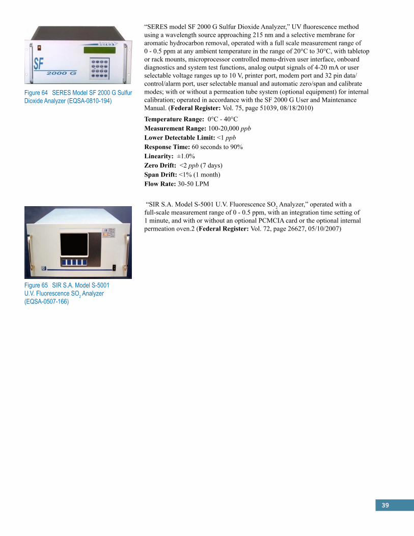
39
Figure 64 SERES Model SF 2000 G Sulfur Dioxide Analyzer (EQSA-0810-194)
“SERES model SF 2000 G Sulfur Dioxide Analyzer,” UV fluorescence method using a wavelength source approaching 215 nm and a selective membrane for aromatic hydrocarbon removal, operated with a full scale measurement range of 0 - 0.5 ppm at any ambient temperature in the range of 20°C to 30°C, with tabletop or rack mounts, microprocessor controlled menu-driven user interface, onboard diagnostics and system test functions, analog output signals of 4-20 mA or user selectable voltage ranges up to 10 V, printer port, modem port and 32 pin data/control/alarm port, user selectable manual and automatic zero/span and calibrate modes; with or without a permeation tube system (optional equipment) for internal calibration; operated in accordance with the SF 2000 G User and Maintenance Manual. (Federal Register: Vol. 75, page 51039, 08/18/2010)
Temperature Range: 0°C - 40°CMeasurement Range: 100-20,000 ppbLower Detectable Limit: <1 ppbResponse Time: 60 seconds to 90%Linearity: ±1.0%Zero Drift: <2 ppb (7 days)Span Drift: <1% (1 month)Flow Rate: 30-50 LPM
“SIR S.A. Model S-5001 U.V. Fluorescence SO2 Analyzer,” operated with a full-scale measurement range of 0 - 0.5 ppm, with an integration time setting of 1 minute, and with or without an optional PCMCIA card or the optional internal permeation oven.2 (Federal Register: Vol. 72, page 26627, 05/10/2007)
Figure 65 SIR S.A. Model S-5001 U.V. Fluorescence SO2 Analyzer (EQSA-0507-166)

40
Figure 66 Teledyne Advanced Pollution Instrumentation, Models 100A, 100AS, 100E, 100EU, T100, T100U; Teledyne Analytical Instruments Model 6400A; or Teledyne Monitor Labs sensor-e™ Model TML-50 SO2 Analyzers; or recordum airpointer® system module 801-001000 (EQSA-0495-100)
‘Teledyne Advanced Pollution Instrumentation Models 100A, 100AS, 100E, 100EU, T100 or T100U; Teledyne Analytical Instruments Model 6400A; or Teledyne Monitor Labs, Inc. sensor-e™ Model TML-50 UV Fluorescent Sulfur Dioxide Analyzer; operated on any full scale range between 0-50 ppb and 0-1000 ppb, at any temperature in the range of 5 to 40 degrees C, with a TFE filter element or a Kynar® DFU installed in the filter assembly, with either the vendor-supplied internal pump or a user- or vender-supplied external vacuum pump capable of maintaining an absolute pressure of 35 cm (14 inches) of mercury (or less) at 1.0 standard liter per minute flow rate, with the following software settings: Dynamic zero: OFF or ON; Dynamic span: OFF; AutoCal: ON or OFF; Dual range: ON or OFF; Autorange: ON or OFF; Temp/pressure compensation: ON; dilution factor: OFF or 1.0; and with or without any of the following options (if available for the various models):2 Rack mount with or without chassis slides; Fluorocarbon zero/span valves; Internal zero/span (IZS); Three-point internal zero/span (IZS, option 51C); 4-20 mA, isolated analog outputs; analog input option; External pump; Status outputs; Control inputs; Rack mount for external pump with tray; RS-232 output; Ethernet output; Zero air scrubber; Combustion Filter; SO2 Permeation tube, certified or uncertified, 0.4 ppm @ 0.7 L/min; SO2 Permeation tube, certified or uncertified, 0.8 ppm @ 0.7 L/min. Airpointer® module 801-001000 only: operated on any full scale range between 0-0.05 ppm and 0-1.0 ppm, with a PTFE filter element installed in the internal filter assembly, with the software setting: FRM/FEM conform mode; at any temperature in the range of 10°C to 45°C, with either a user- or vendor-supplied vacuum pump capable of providing an absolute pressure of 16 inches mercury or less at 2.5 sLpm; installed in the compact. thermally controlled (-40°C to + 45°C) and weather proof airpointer base unit with integrated data acquisition and management system mounted on a frame, pole, or wall; with or without wireless telemetry; with or without internal span option as module supplement consisting of permeation oven and permeation tube; with or without modules for other criteria pollutants; with or without analyzer for particulate matter; with or without additional 3rd party sensors for e.g. meteorology, noise, or traffic counting. Operated with the appropriate instrument manual. Note 2 applies to the following Teledyne Advanced Pollution Instrumentation, Models 100E, 100EU, T100, T100U, and Teledyne Monitor Labs, Inc. Sensor-eTM Model TML-50. (Federal Register: Vol. 60, page 17061, 04/04/1995 Latest Modification: 08/2010; 05/2013; 07/2014) (Specifications are for Teledyne T100)
Measurement Range: 0-20,000 ppbZero Drift: <0.5 ppb (24 hours)Span Drift: <0.5% of full scale (24 hours)Response Time: 20 secondsLinearity: 1% of full scalePrecision: 0.5% of readingFlow Rate: 650 cm3/minTemperature Range: 5°C - 40°C
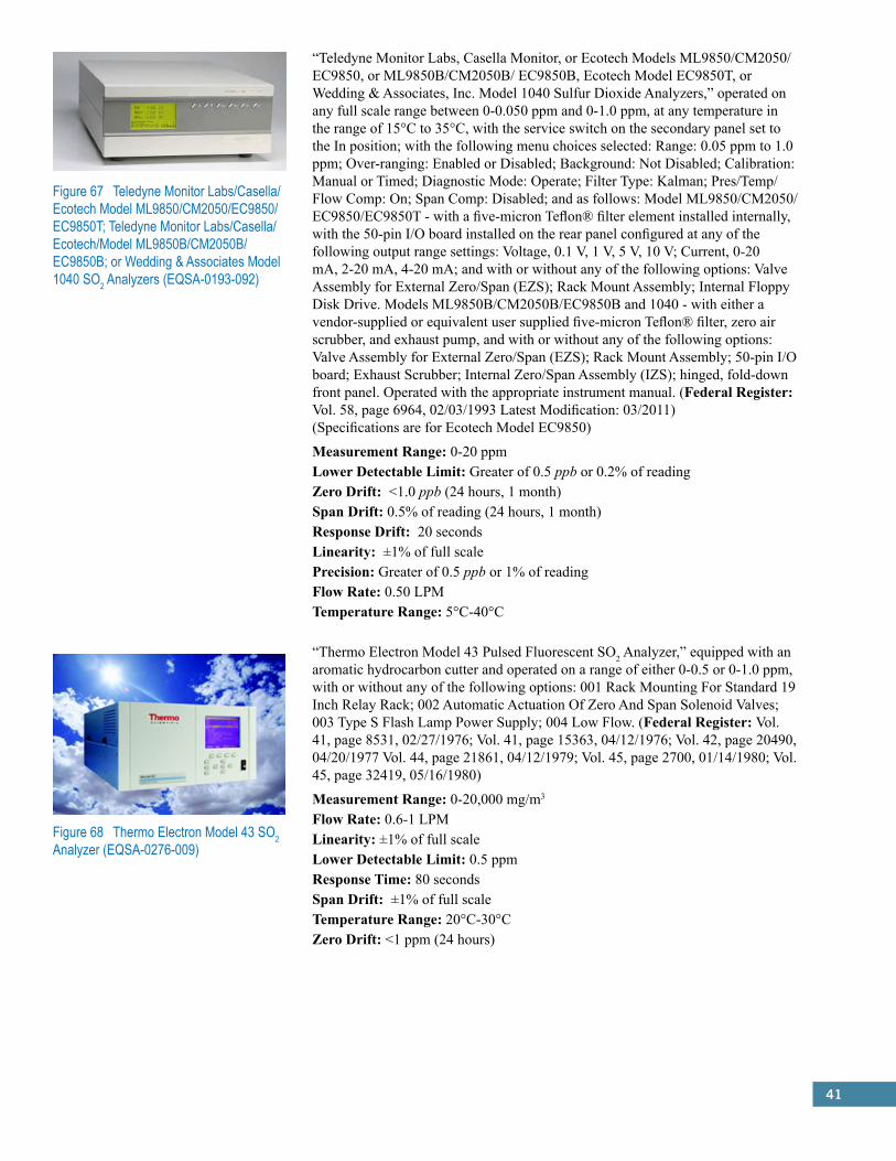
41
Figure 67 Teledyne Monitor Labs/Casella/Ecotech Model ML9850/CM2050/EC9850/EC9850T; Teledyne Monitor Labs/Casella/ Ecotech/Model ML9850B/CM2050B/EC9850B; or Wedding & Associates Model 1040 SO2 Analyzers (EQSA-0193-092)
“Teledyne Monitor Labs, Casella Monitor, or Ecotech Models ML9850/CM2050/EC9850, or ML9850B/CM2050B/ EC9850B, Ecotech Model EC9850T, or Wedding & Associates, Inc. Model 1040 Sulfur Dioxide Analyzers,” operated on any full scale range between 0-0.050 ppm and 0-1.0 ppm, at any temperature in the range of 15°C to 35°C, with the service switch on the secondary panel set to the In position; with the following menu choices selected: Range: 0.05 ppm to 1.0 ppm; Over-ranging: Enabled or Disabled; Background: Not Disabled; Calibration: Manual or Timed; Diagnostic Mode: Operate; Filter Type: Kalman; Pres/Temp/Flow Comp: On; Span Comp: Disabled; and as follows: Model ML9850/CM2050/ EC9850/EC9850T - with a five-micron Teflon® filter element installed internally, with the 50-pin I/O board installed on the rear panel configured at any of the following output range settings: Voltage, 0.1 V, 1 V, 5 V, 10 V; Current, 0-20 mA, 2-20 mA, 4-20 mA; and with or without any of the following options: Valve Assembly for External Zero/Span (EZS); Rack Mount Assembly; Internal Floppy Disk Drive. Models ML9850B/CM2050B/EC9850B and 1040 - with either a vendor-supplied or equivalent user supplied five-micron Teflon® filter, zero air scrubber, and exhaust pump, and with or without any of the following options: Valve Assembly for External Zero/Span (EZS); Rack Mount Assembly; 50-pin I/O board; Exhaust Scrubber; Internal Zero/Span Assembly (IZS); hinged, fold-down front panel. Operated with the appropriate instrument manual. (Federal Register: Vol. 58, page 6964, 02/03/1993 Latest Modification: 03/2011) (Specifications are for Ecotech Model EC9850)
Measurement Range: 0-20 ppmLower Detectable Limit: Greater of 0.5 ppb or 0.2% of readingZero Drift: <1.0 ppb (24 hours, 1 month)Span Drift: 0.5% of reading (24 hours, 1 month)Response Drift: 20 secondsLinearity: ±1% of full scalePrecision: Greater of 0.5 ppb or 1% of readingFlow Rate: 0.50 LPMTemperature Range: 5°C-40°C
“Thermo Electron Model 43 Pulsed Fluorescent SO2 Analyzer,” equipped with an aromatic hydrocarbon cutter and operated on a range of either 0-0.5 or 0-1.0 ppm, with or without any of the following options: 001 Rack Mounting For Standard 19 Inch Relay Rack; 002 Automatic Actuation Of Zero And Span Solenoid Valves; 003 Type S Flash Lamp Power Supply; 004 Low Flow. (Federal Register: Vol. 41, page 8531, 02/27/1976; Vol. 41, page 15363, 04/12/1976; Vol. 42, page 20490, 04/20/1977 Vol. 44, page 21861, 04/12/1979; Vol. 45, page 2700, 01/14/1980; Vol. 45, page 32419, 05/16/1980)
Measurement Range: 0-20,000 mg/m3
Flow Rate: 0.6-1 LPMLinearity: ±1% of full scaleLower Detectable Limit: 0.5 ppmResponse Time: 80 secondsSpan Drift: ±1% of full scaleTemperature Range: 20°C-30°CZero Drift: <1 ppm (24 hours)
Figure 68 Thermo Electron Model 43 SO2 Analyzer (EQSA-0276-009)
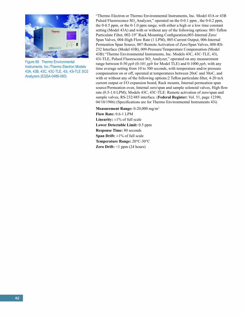
42
Figure 69 Thermo Environmental Instruments, Inc./Thermo Electron Models 43A, 43B, 43C, 43C-TLE, 43i, 43i-TLE SO2 Analyzers (EQSA-0486-060)
“Thermo Electron or Thermo Environmental Instruments, Inc. Model 43A or 43B Pulsed Fluorescence SO2 Analyzer,” operated on the 0-0.1 ppm , the 0-0.2 ppm, the 0-0.5 ppm, or the 0-1.0 ppm range, with either a high or a low time constant setting (Model 43A) and with or without any of the following options: 001-Teflon Particulate Filter, 002-19” Rack Mounting Configuration,003-Internal Zero/Span Valves, 004-High Flow Rate (1 LPM), 005-Current Output, 006-Internal Permeation Span Source, 007-Remote Activation of Zero/Span Valves, 008-RS-232 Interface (Model 43B), 009-Pressure/Temperature Compensation (Model 43B).“Thermo Environmental Instruments, Inc. Models 43C, 43C-TLE, 43i, 43i-TLE, Pulsed Fluorescence SO2 Analyzer,” operated on any measurement range between 0-50 ppb (0-101 ppb for Model TLE) and 0-1000 ppb, with any time average setting from 10 to 300 seconds, with temperature and/or pressure compensation on or off, operated at temperatures between 20oC and 30oC, and with or without any of the following options:2 Teflon particulate filter, 4-20 mA current output or I/O expansion board, Rack mounts, Internal permeation span source/Permeation oven, Internal zero/span and sample solenoid valves, High flow rate (0.5-1.0 LPM); Models 43C, 43C-TLE: Remote activation of zero/span and sample valves, RS-232/485 interface. (Federal Register: Vol. 51, page 12390, 04/10/1986) (Specifications are for Thermo Environmental Instruments 43i)
Measurement Range: 0-20,000 mg/m3
Flow Rate: 0.6-1 LPMLinearity: ±1% of full scaleLower Detectable Limit: 0.5 ppmResponse Time: 80 secondsSpan Drift: ±1% of full scaleTemperature Range: 20°C-30°CZero Drift: <1 ppm (24 hours)

43
5.0 Federal Reference Methods (FRM) and Federal Equivalent Methods (FEMs):Ozone (O3)
Criteria Pollutant: Ozone (O3)
Federal Reference Method (FRM): Ethylene Chemiluminescence (CFR 40, Part 50, App. D)Theory of Operation:Theory relies on the method of measurement described in Appendix D of 40 CFR, Part 50: “Ambient air and ethylene are delivered simultaneously to a mixing zone where the ozone in the air reacts with the ethylene to emit light, which is detected by a photomultiplier tube. The resulting photocurrent is amplified and is either read directly or displayed on a recorder.”
Interferences:Water vapor is one of the most common interferences in the chemiluminescence process. Calibration performed to the manufacturer’s specifications, must occur to reduce error from this interference.
Advantages:Interferences are rarely an issue with chemiluminescence, as water vapor is the only potential complication. With proper adjustments, error from interferences can be reduced greatly.
Method Status:While chemiluminescence was the method of choice for older devices, newer devices rely on it less and less. Still, it is a reliable and valid method of measurement of O3. METHOD IS NO LONGER COMMERCIALLY AVAILABLE. Note: The Nitrous Oxide (NO) Federal Equivalent Method for ozone was recommended by the U.S. Environmental Protection Agency’s Clean Air Scientific Advisory Committee’s (CASAC) Air Monitoring and Methods Subcommittee (AMMS) as a second FRM for ozone during June and July 2014.
The following list is the entirety of approved FRM devices for the measurement of O3 using Gas Phase Chemiluminescence:
Beckman Model 950A Ozone Analyzer (RFOA-0577-020)*“Beckman Model 950A Ozone Analyzer,” operated on a range of 0-0.5 ppm and with the “SLOW” (60-second) response time, with or without any of the following options: Internal Ozone Generator; Computer Adaptor Kit; Pure Ethylene Accessory. (Federal Register: Vol. 42, page 28571, 06/03/1977)
Bendix or Combustion Engineering Model 8002 Ozone Analyzer (RFOA-0176-007)*“Bendix or Combustion Engineering Model 8002 Ozone Analyzer,” operated on the 0-0.5 ppm range, with a 40-second time constant, with or without any of the following options: Rack Mounting with Chassis Slides; Rack Mounting without Chassis Slides; Zero and Span Timer, Ethylene/CO2 Blend Reactant Gas. (Federal Register: Vol. 41, page 5145, 02/04/1976 and Vol. 45, page 18474, 03/21/1980)
Columbia Scientific Industries Model 2000 Ozone Meter (RFOA-0279-036)*“Columbia Scientific Industries Model 2000 Ozone Meter,” when operated on the 0-0.5 ppm range with either AC or battery power: The BCA 952 battery charger/AC adapter M952-0002 (115V) or M952-0003 (230V) is required for AC operation; an internal battery M952-0006 or 12 volt external battery is required for portable non-AC powered operation. (Federal Register: Vol. 44, page 10429, 02/20/1979)
McMillan (MEC) Models 1100-1, 1100-2, and 1100-3 Ozone Meters: “MEC Model 1100-1 Ozone Meter,” (RFOA-1076-014), “MEC Model 1100-2 Ozone Meter,” (RFOA-1076-015), “MEC Model 1100-3 Ozone Meter,’ (RFOA-1076-016)*Operated on a 0-0.5 ppm range, with or without any of the following options: 0011 Rack Mounting Ears; 0026 Alarm Set Feature; 0012 Instrument Bail; 0033 Local-Remote Sample; Zero, Span Kit Blend Feature; 0016 Chassis Slide Kit; 0040 Ethylene/CO2. (Federal Register: Vol. 41, page 46647, 10/22/1976 and Vol. 42, page 30235, 06/13/1977)
*Photo Not Available
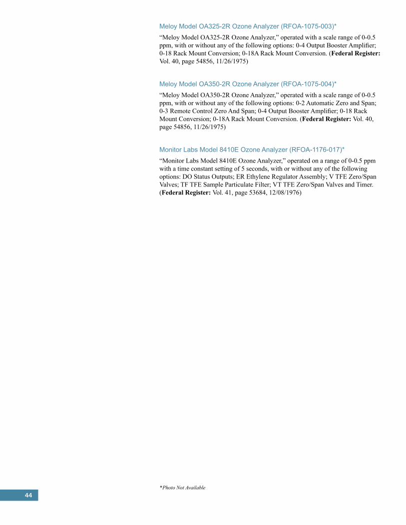
44
Meloy Model OA325-2R Ozone Analyzer (RFOA-1075-003)*“Meloy Model OA325-2R Ozone Analyzer,” operated with a scale range of 0-0.5 ppm, with or without any of the following options: 0-4 Output Booster Amplifier; 0-18 Rack Mount Conversion; 0-18A Rack Mount Conversion. (Federal Register: Vol. 40, page 54856, 11/26/1975)
Meloy Model OA350-2R Ozone Analyzer (RFOA-1075-004)*“Meloy Model OA350-2R Ozone Analyzer,” operated with a scale range of 0-0.5 ppm, with or without any of the following options: 0-2 Automatic Zero and Span; 0-3 Remote Control Zero And Span; 0-4 Output Booster Amplifier; 0-18 Rack Mount Conversion; 0-18A Rack Mount Conversion. (Federal Register: Vol. 40, page 54856, 11/26/1975)
Monitor Labs Model 8410E Ozone Analyzer (RFOA-1176-017)*“Monitor Labs Model 8410E Ozone Analyzer,” operated on a range of 0-0.5 ppm with a time constant setting of 5 seconds, with or without any of the following options: DO Status Outputs; ER Ethylene Regulator Assembly; V TFE Zero/Span Valves; TF TFE Sample Particulate Filter; VT TFE Zero/Span Valves and Timer. (Federal Register: Vol. 41, page 53684, 12/08/1976)
*Photo Not Available
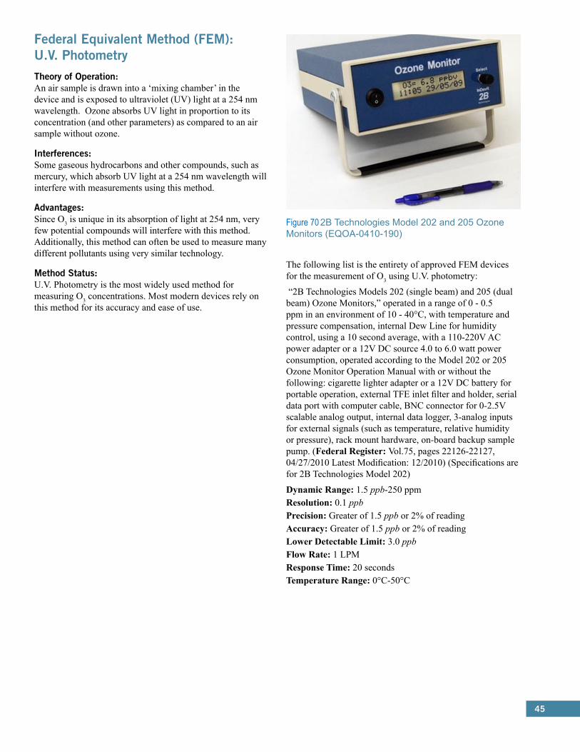
45
Federal Equivalent Method (FEM): U.V. PhotometryTheory of Operation:An air sample is drawn into a ‘mixing chamber’ in the device and is exposed to ultraviolet (UV) light at a 254 nm wavelength. Ozone absorbs UV light in proportion to its concentration (and other parameters) as compared to an air sample without ozone.
Interferences:Some gaseous hydrocarbons and other compounds, such as mercury, which absorb UV light at a 254 nm wavelength will interfere with measurements using this method.
Advantages:Since O3 is unique in its absorption of light at 254 nm, very few potential compounds will interfere with this method. Additionally, this method can often be used to measure many different pollutants using very similar technology.
Method Status:U.V. Photometry is the most widely used method for measuring O3 concentrations. Most modern devices rely on this method for its accuracy and ease of use.
The following list is the entirety of approved FEM devices for the measurement of O3 using U.V. photometry:
“2B Technologies Models 202 (single beam) and 205 (dual beam) Ozone Monitors,” operated in a range of 0 - 0.5 ppm in an environment of 10 - 40°C, with temperature and pressure compensation, internal Dew Line for humidity control, using a 10 second average, with a 110-220V AC power adapter or a 12V DC source 4.0 to 6.0 watt power consumption, operated according to the Model 202 or 205 Ozone Monitor Operation Manual with or without the following: cigarette lighter adapter or a 12V DC battery for portable operation, external TFE inlet filter and holder, serial data port with computer cable, BNC connector for 0-2.5V scalable analog output, internal data logger, 3-analog inputs for external signals (such as temperature, relative humidity or pressure), rack mount hardware, on-board backup sample pump. (Federal Register: Vol.75, pages 22126-22127, 04/27/2010 Latest Modification: 12/2010) (Specifications are for 2B Technologies Model 202)
Dynamic Range: 1.5 ppb-250 ppmResolution: 0.1 ppbPrecision: Greater of 1.5 ppb or 2% of readingAccuracy: Greater of 1.5 ppb or 2% of readingLower Detectable Limit: 3.0 ppbFlow Rate: 1 LPMResponse Time: 20 secondsTemperature Range: 0°C-50°C
Figure 70 2B Technologies Model 202 and 205 Ozone Monitors (EQOA-0410-190)
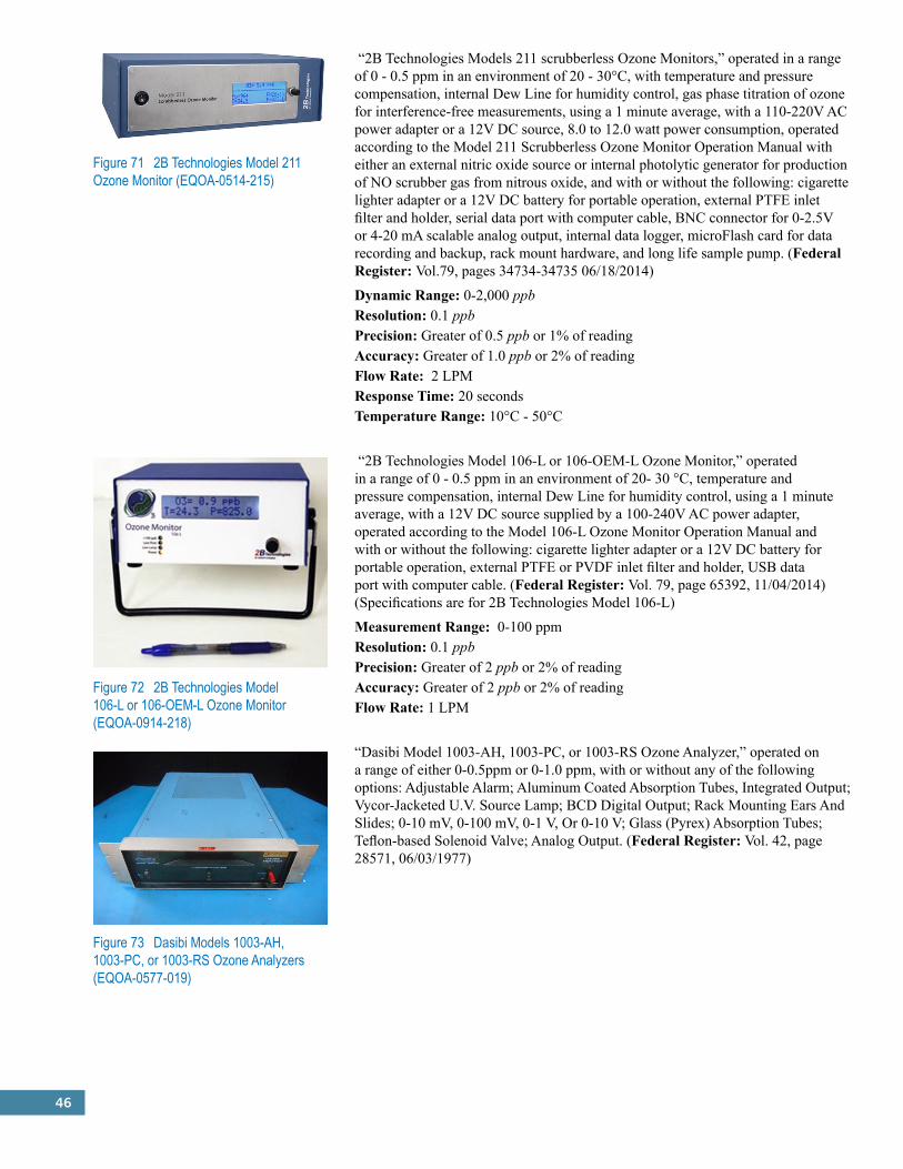
46
Figure 71 2B Technologies Model 211 Ozone Monitor (EQOA-0514-215)
“2B Technologies Models 211 scrubberless Ozone Monitors,” operated in a range of 0 - 0.5 ppm in an environment of 20 - 30°C, with temperature and pressure compensation, internal Dew Line for humidity control, gas phase titration of ozone for interference-free measurements, using a 1 minute average, with a 110-220V AC power adapter or a 12V DC source, 8.0 to 12.0 watt power consumption, operated according to the Model 211 Scrubberless Ozone Monitor Operation Manual with either an external nitric oxide source or internal photolytic generator for production of NO scrubber gas from nitrous oxide, and with or without the following: cigarette lighter adapter or a 12V DC battery for portable operation, external PTFE inlet filter and holder, serial data port with computer cable, BNC connector for 0-2.5V or 4-20 mA scalable analog output, internal data logger, microFlash card for data recording and backup, rack mount hardware, and long life sample pump. (Federal Register: Vol.79, pages 34734-34735 06/18/2014)
Dynamic Range: 0-2,000 ppbResolution: 0.1 ppbPrecision: Greater of 0.5 ppb or 1% of readingAccuracy: Greater of 1.0 ppb or 2% of readingFlow Rate: 2 LPMResponse Time: 20 secondsTemperature Range: 10°C - 50°C
“2B Technologies Model 106-L or 106-OEM-L Ozone Monitor,” operated in a range of 0 - 0.5 ppm in an environment of 20- 30 °C, temperature and pressure compensation, internal Dew Line for humidity control, using a 1 minute average, with a 12V DC source supplied by a 100-240V AC power adapter, operated according to the Model 106-L Ozone Monitor Operation Manual and with or without the following: cigarette lighter adapter or a 12V DC battery for portable operation, external PTFE or PVDF inlet filter and holder, USB data port with computer cable. (Federal Register: Vol. 79, page 65392, 11/04/2014)(Specifications are for 2B Technologies Model 106-L)
Measurement Range: 0-100 ppmResolution: 0.1 ppbPrecision: Greater of 2 ppb or 2% of readingAccuracy: Greater of 2 ppb or 2% of readingFlow Rate: 1 LPM
“Dasibi Model 1003-AH, 1003-PC, or 1003-RS Ozone Analyzer,” operated on a range of either 0-0.5ppm or 0-1.0 ppm, with or without any of the following options: Adjustable Alarm; Aluminum Coated Absorption Tubes, Integrated Output; Vycor-Jacketed U.V. Source Lamp; BCD Digital Output; Rack Mounting Ears And Slides; 0-10 mV, 0-100 mV, 0-1 V, Or 0-10 V; Glass (Pyrex) Absorption Tubes; Teflon-based Solenoid Valve; Analog Output. (Federal Register: Vol. 42, page 28571, 06/03/1977)
Figure 72 2B Technologies Model 106-L or 106-OEM-L Ozone Monitor (EQOA-0914-218)
Figure 73 Dasibi Models 1003-AH, 1003-PC, or 1003-RS Ozone Analyzers (EQOA-0577-019)

47
“Dasibi Model 1008-AH, 1008-PC, or 1008-RS Ozone Analyzer,” operated on a range of either 0-0.5 ppm or 0-1.0 ppm, with or without any of the following options: Aluminum Coated Absorption Tubes; BCD Digital Output; RS232 Interface; Glass (Pyrex) Absorption Tubes; Vycor-Jacketed U.V. Source Lamp; Ozone Generator; Teflon-based Solenoid Valve; Photometer Flow Restrictor (2 LPM); 4-20 mA, Isolated, Or Dual Analog Outputs; Rack Mounting Brackets Or Slides; 20 Second Update Software. (Federal Register: Vol. 48, page 10126, 03/10/1983) (Specifications are for all three models)
Measurement Range: 0-1.0 ppmFlow Rate: 2 LPMPrecision: 0.001 ppmTemperature Range: 0°C-45°CZero Drift: 0.5% of readingSpan Drift: ±0% of readingResponse Time: 50 seconds
DKK-TOA Corp. Model GUX-113E Ozone Analyzer (EQOA-0200-134)*“DKK-TOA Corporation Models GUX-113E and GUX-113E-1 Ozone Analyzer,” operated at any temperature in the range of 15oC to 35oC, on any of the following measurement ranges: 0-0.100 ppm, 0-0.200 ppm, 0-0.5 ppm, or 0-1.000 ppm, and with or without the optional Internal Ozone Generator. (Federal Register: Vol. 65, page 11308, 03/02/2000)
“DKK-TOA Corporation Model GUX-313E Ambient O3 Analyzer,” operated at any environmental temperature in the range of 20oC to 30oC on any of the following measurement ranges: 0-0.1 ppm, 0-0.2 ppm and 0-0.5 ppm. (Federal Register: Vol. 72, page 63176, 11/08/2007)
Lower Detectable Limit: 0.5 ppbZero Drift: ±1 ppb (24 hours)Span Drift: ±1% (24 hours0Temperature Range: 0°C-40°C
“Ecotech Serinus 10 Ozone Analyzer” or “Opsis AB OPS10 Ozone Analyzer” or “Tisch Environmental TE 1.0 Ozone Analyzer,” operated in the range of 0–0.5 ppm, with a five-micron Teflon® filter element installed, and with the following selected: Control Loop-Enabled, Diagnostic Mode-Operate, Pres/Temp/Flow Compensation-Enabled, Span Compensation-Disabled, with concentration automatically corrected for temperature and pressure changes, and operated according to the Serinus 10 Ozone Analyzer User Manual, or the Opsis AB OPS10 Ozone Analyzer User Manual, or the Tisch Environmental TE 1.0 Ozone Analyzer Instruction Manual, as appropriate. (Federal Register: Vol. 74, page 38184, 07/31/2009 Latest Modifications: 05/2010, 05/2012, 8/2014) (Specifications are for Ecotech Serinus 10)
Measurement Range: 0-20 ppmPrecision: Greater of 0.5 ppb or 0.2% of readingLinearity: <1% of full scaleResponse Time: 30 secondsFlow Rate: 0.5 LPMZero Drift: <0.3 ppb (24 hours, 7 days)Span Drift: 0.5% of reading (7 days)
Figure 74 Dasibi Models 1008-AH, 1008-PC, or 1008-RS Ozone Analyzers (EQOA-0383-056)
Figure 75 DKK-TOA Corp. Model GUX-313E Ambient O3 Analyzer (EQOA-1107-169)
Figure 76 Ecotech Serinus 10 Ozone Analyzer or Opsis AB OPS10 Ozone Analyzer or Tisch Environmental TE 1.0 Ozone Analyzer (EQOA-0809-187)
*Photo Not Available
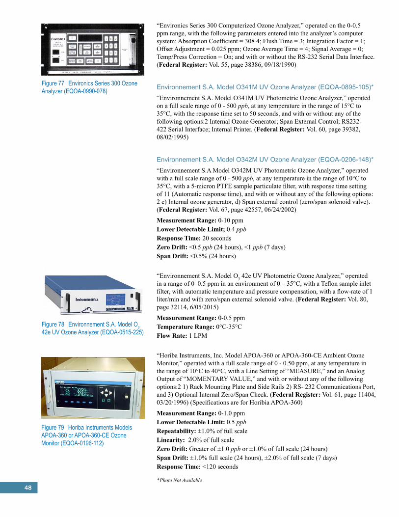
48
Figure 77 Environics Series 300 Ozone Analyzer (EQOA-0990-078)
“Environics Series 300 Computerized Ozone Analyzer,” operated on the 0-0.5 ppm range, with the following parameters entered into the analyzer’s computer system: Absorption Coefficient = 308 4; Flush Time = 3; Integration Factor = 1; Offset Adjustment = 0.025 ppm; Ozone Average Time = 4; Signal Average = 0; Temp/Press Correction = On; and with or without the RS-232 Serial Data Interface. (Federal Register: Vol. 55, page 38386, 09/18/1990)
Environnement S.A. Model O341M UV Ozone Analyzer (EQOA-0895-105)*“Environnement S.A. Model O341M UV Photometric Ozone Analyzer,” operated on a full scale range of 0 - 500 ppb, at any temperature in the range of 15°C to 35°C, with the response time set to 50 seconds, and with or without any of the following options:2 Internal Ozone Generator; Span External Control; RS232-422 Serial Interface; Internal Printer. (Federal Register: Vol. 60, page 39382, 08/02/1995)
Environnement S.A. Model O342M UV Ozone Analyzer (EQOA-0206-148)*“Environnement S.A Model O342M UV Photometric Ozone Analyzer,” operated with a full scale range of 0 - 500 ppb, at any temperature in the range of 10°C to 35°C, with a 5-micron PTFE sample particulate filter, with response time setting of 11 (Automatic response time), and with or without any of the following options: 2 c) Internal ozone generator, d) Span external control (zero/span solenoid valve). (Federal Register: Vol. 67, page 42557, 06/24/2002)
Measurement Range: 0-10 ppmLower Detectable Limit;� 0.4 ppbResponse Time: 20 secondsZero Drift: <0.5 ppb (24 hours), <1 ppb (7 days)Span Drift: <0.5% (24 hours)
“Environnement S.A. Model O3 42e UV Photometric Ozone Analyzer,” operated in a range of 0–0.5 ppm in an environment of 0 – 35°C, with a Teflon sample inlet filter, with automatic temperature and pressure compensation, with a flow-rate of 1 liter/min and with zero/span external solenoid valve. (Federal Register: Vol. 80, page 32114, 6/05/2015)
Measurement Range: 0-0.5 ppmTemperature Range: 0°C-35°CFlow Rate: 1 LPM
“Horiba Instruments, Inc. Model APOA-360 or APOA-360-CE Ambient Ozone Monitor,” operated with a full scale range of 0 - 0.50 ppm, at any temperature in the range of 10°C to 40°C, with a Line Setting of “MEASURE,” and an Analog Output of “MOMENTARY VALUE,” and with or without any of the following options:2 1) Rack Mounting Plate and Side Rails 2) RS- 232 Communications Port, and 3) Optional Internal Zero/Span Check. (Federal Register: Vol. 61, page 11404, 03/20/1996) (Specifications are for Horibia APOA-360)
Measurement Range: 0-1.0 ppmLower Detectable Limit: 0.5 ppbRepeatability: ±1.0% of full scaleLinearity: 2.0% of full scaleZero Drift: Greater of ±1.0 ppb or ±1.0% of full scale (24 hours)Span Drift: ±1.0% full scale (24 hours), ±2.0% of full scale (7 days)Response Time: <120 seconds
Figure 78 Environnement S.A. Model O3 42e UV Ozone Analyzer (EQOA-0515-225)
Figure 79 Horiba Instruments Models APOA-360 or APOA-360-CE Ozone Monitor (EQOA-0196-112)
*Photo Not Available
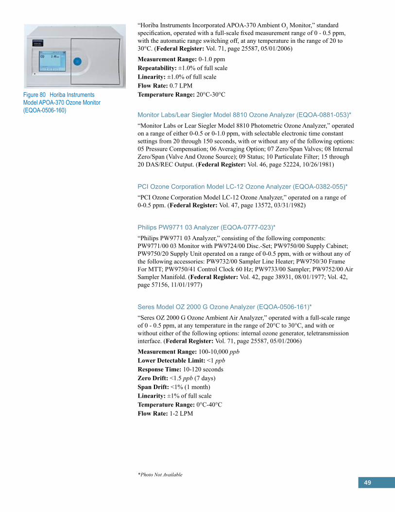
49
Figure 80 Horiba Instruments Model APOA-370 Ozone Monitor (EQOA-0506-160)
“Horiba Instruments Incorporated APOA-370 Ambient O3 Monitor,” standard specification, operated with a full-scale fixed measurement range of 0 - 0.5 ppm, with the automatic range switching off, at any temperature in the range of 20 to 30°C. (Federal Register: Vol. 71, page 25587, 05/01/2006)
Measurement Range: 0-1.0 ppmRepeatability: ±1.0% of full scaleLinearity: ±1.0% of full scaleFlow Rate: 0.7 LPMTemperature Range: 20°C-30°C
Monitor Labs/Lear Siegler Model 8810 Ozone Analyzer (EQOA-0881-053)*“Monitor Labs or Lear Siegler Model 8810 Photometric Ozone Analyzer,” operated on a range of either 0-0.5 or 0-1.0 ppm, with selectable electronic time constant settings from 20 through 150 seconds, with or without any of the following options: 05 Pressure Compensation; 06 Averaging Option; 07 Zero/Span Valves; 08 Internal Zero/Span (Valve And Ozone Source); 09 Status; 10 Particulate Filter; 15 through 20 DAS/REC Output. (Federal Register: Vol. 46, page 52224, 10/26/1981)
PCI Ozone Corporation Model LC-12 Ozone Analyzer (EQOA-0382-055)*“PCI Ozone Corporation Model LC-12 Ozone Analyzer,” operated on a range of 0-0.5 ppm. (Federal Register: Vol. 47, page 13572, 03/31/1982)
Philips PW9771 03 Analyzer (EQOA-0777-023)*“Philips PW9771 03 Analyzer,” consisting of the following components: PW9771/00 03 Monitor with PW9724/00 Disc.-Set; PW9750/00 Supply Cabinet; PW9750/20 Supply Unit operated on a range of 0-0.5 ppm, with or without any of the following accessories: PW9732/00 Sampler Line Heater; PW9750/30 Frame For MTT; PW9750/41 Control Clock 60 Hz; PW9733/00 Sampler; PW9752/00 Air Sampler Manifold. (Federal Register: Vol. 42, page 38931, 08/01/1977; Vol. 42, page 57156, 11/01/1977)
Seres Model OZ 2000 G Ozone Analyzer (EQOA-0506-161)*“Seres OZ 2000 G Ozone Ambient Air Analyzer,” operated with a full-scale range of 0 - 0.5 ppm, at any temperature in the range of 20°C to 30°C, and with or without either of the following options: internal ozone generator, teletransmission interface. (Federal Register: Vol. 71, page 25587, 05/01/2006)
Measurement Range: 100-10,000 ppbLower Detectable Limit: <1 ppbResponse Time: 10-120 secondsZero Drift: <1.5 ppb (7 days)Span Drift: <1% (1 month)Linearity: ±1% of full scaleTemperature Range: 0°C-40°CFlow Rate: 1-2 LPM
*Photo Not Available

50
“SIR S.A. Model S-5014 Photometric O3 Analyzer,” operated on the 0 - 500 ppb measurement range, within an ambient temperature range of 20°C to 30°C, with a sample inlet particulate filter, and with or without an optional PCMCIA card. (Federal Register: Vol. 72, page 8985, 02/28/2007)
Measurement Ranges: 0-1,000 ppbLower Detectable Limit: 0.6 ppbZero Drift: <0.5 ppb (1 month)Span Drift: <0.5 ppb (1 month)Response Time: 15 secondsPrecision: 1 ppbLinearity: ±1%Temperature Range: 5°C-40°CFlow Rate: 1.5 LPM
Sutron Corporation Model 6030 O3 Analyzer (EQOA-0415-222)* “Sutron Model 6030 Ozone Analyzer,” operated at any of the following measurement ranges: 0-0.05 ppm, 0-0.5 ppm and 0- 1.0 ppm, at any ambient temperature in the range of 5°C -45 °C, with an averaging time of 1 to 99 analyzer cycles (0 to 396 seconds), with sample flow rate of 0.5 to 1 Lpm and in accordance with the Model 6030 Ozone Analyzer Operation Manual and with or without the following options: internal ozone generator, zero/span ports for external calibration. (Federal Register: Vol. 80, page 32114, 6/05/2015)
Measurement Range: 0-500 ppbLower Detectable Limit: 1 ppbZero Drift: <1.0 ppb (24 hours), <2.0 ppb (7 days)Span Drift: <1% (1 month)Response Time: 20 secondsLinearity: ±1% of full scaleFlow Rate: 1 LPMOperating Temperature: 5°C-45°C
Tanabyte Models 722, 723, 724, 725, or 726 Ambient Ozone Analyzer (EQOA-0407-165)*“Tanabyte Models 722,723, 724, 725, or 726 Ambient Ozone Analyzer,” enclosed in either a Dual-Bay Chassis or a Single-Bay Chassis and operated on either the 0 - 0.5 ppm or 0 - 1.0 ppm measurement range, within an ambient temperature range of 20 to 30°C, and with a sample inlet particulate filter installed in the sample filter holder. (Federal Register: Vol. 72, page 20846, 04/26/2007)
Figure 81 SIR S.A. Model S-5014 O3 Analyzer (EQOA-0207-164)
*Photo Not Available
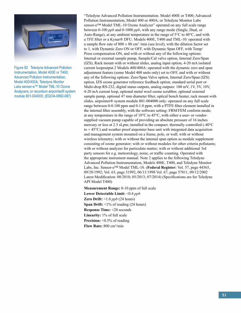
51
“Teledyne Advanced Pollution Instrumentation. Model 400E or T400; Advanced Pollution Instrumentation, Model 400 or 400A; or Teledyne Monitor Labs sensor-e™ Model TML-10 Ozone Analyzer” operated on any full scale range between 0-100 ppb and 0-1000 ppb, with any range mode (Single, Dual, or Auto-Range), at any ambient temperature in the range of 5°C to 40°C, and with a TFE filter or a Kynar® DFU. Models 400E, T400 and TML-10: operated with a sample flow rate of 800 ± 80 cm3 /min (sea level), with the dilution factor set to 1, with Dynamic Zero ON or OFF, with Dynamic Span OFF, with Temp/Press compensation ON, and with or without any of the following options: Internal or external sample pump, Sample/Cal valve option, Internal Zero/Span (IZS), Rack mount with or without slides, analog input option, 4-20 mA isolated current loopoutput.2 Models 400/400A: operated with the dynamic zero and span adjustment feature (some Model 400 units only) set to OFF, and with or without any of the following options: Zero/Span Valve option, Internal Zero/Span (IZS) option, IZS ozone generator reference feedback option, standard serial port or Multi-drop RS-232, digital status outputs, analog outputs: 100 mV, 1V, 5V, 10V, 4-20 mA current loop, optional metal wool ozone scrubber, optional external sample pump, optional 47 mm diameter filter, optical bench heater, rack mount with slides. airpointer® system module 801-004000 only: operated on any full scale range between 0-0.100 ppm and 0-1.0 ppm, with a PTFE filter element installed in the internal filter assembly, with the software setting: FRM/FEM conform mode; at any temperature in the range of 10°C to 45°C, with either a user- or vendor-supplied vacuum pump capable of providing an absolute pressure of 16 inches mercury or less at 2.5 sLpm; installed in the compact. thermally controlled (-40°C to + 45°C) and weather proof airpointer base unit with integrated data acquisition and management system mounted on a frame, pole, or wall; with or without wireless telemetry; with or without the internal span option as module supplement consisting of ozone generator; with or without modules for other criteria pollutants; with or without analyzer for particulate matter; with or without additional 3rd party sensors for e.g. meteorology, noise, or traffic counting. Operated with the appropriate instrument manual. Note 2 applies to the following Teledyne Advanced Pollution Instrumentation, Models 400E, T400, and Teledyne Monitor Labs, Inc. Sensor-e™ Model TML-10. (Federal Register: Vol. 57, page 44565, 09/28/1992; Vol. 63, page 31992, 06/11/1998 Vol. 67, page 57811, 09/12/2002 Latest Modification: 08/2010; 05/2013; 07/2014) (Specifications are for Teledyne API Model T400)
Measurement Range: 0-10 ppm of full scaleLower Detectable Limit: <0.4 ppbZero Drift: <1.0 ppb (24 hours)Span Drift: <1% of reading (24 hours)Response Time: <20 secondsLinearity: 1% of full scalePrecision: <0.5% of readingFlow Rate: 800 cm3/min
Figure 82 Teledyne Advanced Pollution Instrumentation, Model 400E or T400; Advanced Pollution Instrumentation, Model 400/400A; Teledyne Monitor Labs sensor-e™ Model TML-10 Ozone Analyzers; or recordum airpointer® system module 801-004000; (EQOA-0992-087)
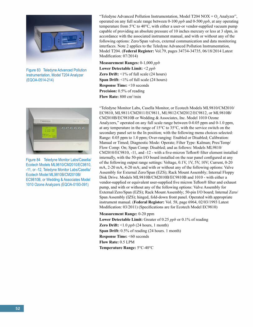
52
Figure 83 Teledyne Advanced Pollution Instrumentation, Model T204 Analyzer (EQOA-0514-214)
“Teledyne Advanced Pollution Instrumentation, Model T204 NOX + O3 Analyzer”, operated on any full scale range between 0-100 ppb and 0-500 ppb, at any operating temperature from 5°C to 40°C, with either a user-or vendor-supplied vacuum pump capable of providing an absolute pressure of 10 inches mercury or less at 3 slpm, in accordance with the associated instrument manual, and with or without any of the following options: Zero/Span valves, external communication and data monitoring interfaces. Note 2 applies to the Teledyne Advanced Pollution Instrumentation, Model T204. (Federal Register: Vol.79, pages 34734-34735, 06/18/2014 Latest Modification: 07/2014)
Measurement Ranges: 0-1,000 ppbLower Detectable Limit: <2 ppbZero Drift: <1% of full scale (24 hours)Span Drift: <1% of full scale (24 hours)Response Time: <10 secondsPrecision: 0.5% of readingFlow Rate: 800 cm3/min
“Teledyne Monitor Labs, Casella Monitor, or Ecotech Models ML9810/CM2010/EC9810, ML9811/CM2011/EC9811, ML9812/CM2012/EC9812, or ML9810B/CM2010B/EC9810B or Wedding & Associates, Inc. Model 1010 Ozone Analyzers,” operated on any full scale range between 0-0.05 ppm and 0-1.0 ppm, at any temperature in the range of 15°C to 35°C, with the service switch on the secondary panel set to the In position; with the following menu choices selected: Range: 0.05 ppm to 1.0 ppm; Over-ranging: Enabled or Disabled; Calibration: Manual or Timed; Diagnostic Mode: Operate; Filter Type: Kalman; Pres/Temp/Flow Comp: On; Span Comp: Disabled; and as follows: Models ML9810/CM2010/EC9810, -11, and -12 - with a five-micron Teflon® filter element installed internally, with the 50-pin I/O board installed on the rear panel configured at any of the following output range settings: Voltage, 0.1V, 1V, 5V, 10V; Current, 0-20 mA, 2-20 mA, 4-20 mA; and with or without any of the following options: Valve Assembly for External Zero/Span (EZS); Rack Mount Assembly; Internal Floppy Disk Drive. Models ML9810B/CM2010B/EC9810B and 1010 - with either a vendor-supplied or equivalent user-supplied five micron Teflon® filter and exhaust pump, and with or without any of the following options: Valve Assembly for External/Zero/Span (EZS); Rack Mount Assembly; 50-pin I/O board; Internal Zero/Span Assembly (IZS); hinged, fold-down front panel. Operated with appropriate instrument manual. (Federal Register: Vol. 58, page 6964, 02/03/1993 Latest Modification: 03/2011) (Specifications are for Ecotech Model EC9810)
Measurement Range: 0-20 ppmLower Detectable Limit: Greater of 0.25 ppb or 0.1% of readingZero Drift: <1.0 ppb (24 hours, 1 month)Span Drift: 0.5% of reading (24 hours. 1 month)Response Time: <60 secondsFlow Rate: 0.5 LPMTemperature Range: 5°C-40°C
Figure 84 Teledyne Monitor Labs/Casella/Ecotech Models ML9810/CM2010/EC9810, -11, or -12, Teledyne Monitor Labs/Casella/Ecotech Model ML9810B/CM2010B/EC9810B, or Wedding & Associates Model 1010 Ozone Analyzers (EQOA-0193-091)
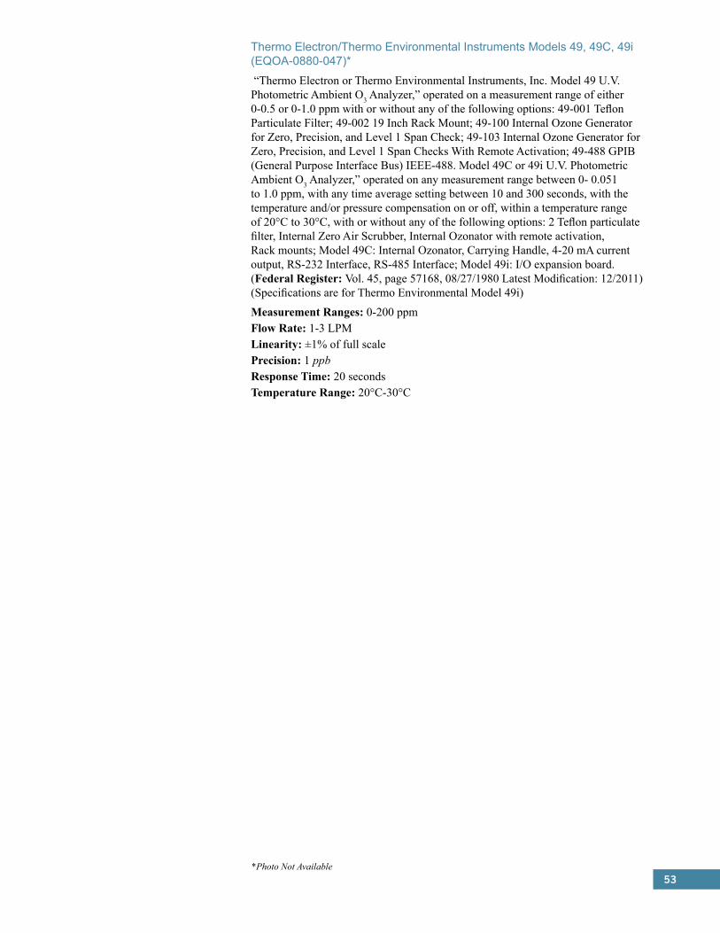
53
Thermo Electron/Thermo Environmental Instruments Models 49, 49C, 49i (EQOA-0880-047)* “Thermo Electron or Thermo Environmental Instruments, Inc. Model 49 U.V. Photometric Ambient O3 Analyzer,” operated on a measurement range of either 0-0.5 or 0-1.0 ppm with or without any of the following options: 49-001 Teflon Particulate Filter; 49-002 19 Inch Rack Mount; 49-100 Internal Ozone Generator for Zero, Precision, and Level 1 Span Check; 49-103 Internal Ozone Generator for Zero, Precision, and Level 1 Span Checks With Remote Activation; 49-488 GPIB (General Purpose Interface Bus) IEEE-488. Model 49C or 49i U.V. Photometric Ambient O3 Analyzer,” operated on any measurement range between 0- 0.051 to 1.0 ppm, with any time average setting between 10 and 300 seconds, with the temperature and/or pressure compensation on or off, within a temperature range of 20°C to 30°C, with or without any of the following options: 2 Teflon particulate filter, Internal Zero Air Scrubber, Internal Ozonator with remote activation, Rack mounts; Model 49C: Internal Ozonator, Carrying Handle, 4-20 mA current output, RS-232 Interface, RS-485 Interface; Model 49i: I/O expansion board. (Federal Register: Vol. 45, page 57168, 08/27/1980 Latest Modification: 12/2011) (Specifications are for Thermo Environmental Model 49i)
Measurement Ranges: 0-200 ppmFlow Rate: 1-3 LPMLinearity: ±1% of full scalePrecision: 1 ppbResponse Time: 20 secondsTemperature Range: 20°C-30°C
*Photo Not Available
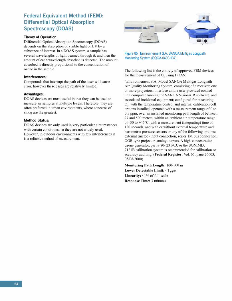
54
Federal Equivalent Method (FEM): Differential Optical Absorption Spectroscopy (DOAS)Theory of Operation:Differential Optical Absorption Spectroscopy (DOAS) depends on the absorption of visible light or UV by a substance of interest. In a DOAS system, a sample has several wavelengths of light beamed through it, and then the amount of each wavelength absorbed is detected. The amount absorbed is directly proportional to the concentration of ozone in the sample.
Interferences:Compounds that interrupt the path of the laser will cause error, however these cases are relatively limited.
Advantages:DOAS devices are most useful in that they can be used to measure air samples at multiple levels. Therefore, they are often preferred in urban environments, where concerns of smog are the greatest.
Method Status:DOAS devices are only used in very particular circumstances with certain conditions, so they are not widely used. However, in outdoor environments with few interferences it is a reliable method of measurement.
Figure 85 Environnement S.A. SANOA Multigas Longpath Monitoring System (EQOA-0400-137)
The following list is the entirety of approved FEM devices for the measurement of O3 using DOAS:
“Environnement S.A. Model SANOA Multigas Longpath Air Quality Monitoring System, consisting of a receiver, one or more projectors, interface unit, a user-provided control unit computer running the SANOA VisionAIR software, and associated incidental equipment; configured for measuring O3, with the temperature control and internal calibration cell options installed, operated with a measurement range of 0 to 0.5 ppm, over an installed monitoring path length of between 27 and 500 meters, within an ambient air temperature range of -30 to +45°C, with a measurement (integrating) time of 180 seconds, and with or without external temperature and barometric pressure sensors or any of the following options: external (meteo) input connection, series 1M bus connection, OGR type projector, analog outputs. A high-concentration ozone generator, part # 80- 231-03, or the SONIMIX 7121B calibration system is recommended for calibration or accuracy auditing. (Federal Register: Vol. 65, page 26603, 05/08/2000)
Monitoring Path Length: 100-500 mLower Detectable Limit: <1 ppbLinearity: <1% of full scaleResponse Time: 3 minutes
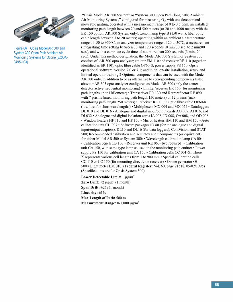
55
Figure 86 Opsis Model AR 500 and System 300 Open Path Ambient Air Monitoring Systems for Ozone (EQOA-0495-103)
“Opsis Model AR 500 System” or “System 300 Open Path (long path) Ambient Air Monitoring Systems,” configured for measuring O3, with one detector and moveable grating, operated with a measurement range of 0 to 0.5 ppm, an installed monitoring path length between 20 and 500 meters (or 20 and 1000 meters with the ER 150 option, AR 500 System only), xenon lamp type B (150 watt), fiber optic cable length between 3 to 20 meters; operating within an ambient air temperature range of -50 to +50°C, an analyzer temperature range of 20 to 30°C, a measurement (integrating) time setting between 30 and 120 seconds (0 min:30 sec. to 2 min:00 sec.), and with a complete cycle time of not more than 200 seconds (3 min, 20 sec.). Under this method designation, the Model AR 500 System or System 300 consists of: AR 500 opto-analyser; emitter EM 110 and receiver RE 110 (together identified as ER 110); optic fibre cable OF60-S; power supply PS 150, Opsis operational software, version 7.0 or 7.1; and initial on-site installation, setup, and limited operator training.2 Optional components that can be used with the Model AR 500 only, in addition to or as alternative to corresponding components listed above: • AR 503 opto-analyzer configured as Model AR 500 (only the center detector active, sequential monitoring) • Emitter/receiver ER 150 (for monitoring path lengths up to1 kilometer) • Transceiver ER 130 and Retroreflector RE 090 with 7 prisms (max. monitoring path length 150 meters) or 12 prisms (max. monitoring path length 250 meters) • Receiver RE 130 • Optic fibre cable OF60-R (low-loss for short wavelengths) • Multiplexers MX 004 and MX 024 • Dataloggers DL 010 and DL 016 • Analogue and digital input/output cards AO 008, AI 016, and DI 032 • Analogue and digital isolation cards IA 008, ID 008, OA 008, and OD 008 • Window heaters HF 110 and HF 150 • Mirror heaters HM 110 and HM 150 • Auto calibration unit CU 007 • Software packages IO 80 (for the analogue and digital input/output adapters), DL10 and DL16 (for data loggers), ComVision, and STAT 500; Recommended calibration and accuracy audit components (or equivalent) for either Model AR 500 or System 300: • Wavelength calibration lamp CA 004 • Calibration bench CB 100 • Receiver unit RE 060 (two required) • Calibration unit CA 150, with same type lamp as used in the monitoring path emitter • Power supply PS 150 for calibration unit CA 150 • Calibration cells CC 001-X, where X represents various cell lengths from 1 to 900 mm • Special calibration cells CC 110 or CC 150 (for mounting directly on receiver) • Ozone generator OC 500 • Light meter LM 010. (Federal Register: Vol. 60, page 21518, 05/02/1995) (Specifications are for Opsis System 300)
Lower Detectable Limit: 1 µg/m3
Zero Drift: ±2 µg/m3 (1 month)Span Drift: ±2% (1 month)Linearity: ±1%Max Length of Path: 500 mMeasurement Range: 0-1,000 µg/m3

57
6.0 Federal Reference Methods (FRM) and Federal Equivalent Methods (FEMs):Carbon Monoxide (CO)Carbon Monoxide (CO):Criteria Pollutant: Carbon Monoxide (CO)
Federal Reference Method (FRM): Non-Dispersive Infrared Photometry (CFR 40, Part 50, App. C)Theory of Operation:Non-dispersive infrared photometry (NDIR) monitors rely on the method of measurement described in Appendix C of 40 CFR, Part 50: “Measurements are based on the absorption of infrared radiation by carbon monoxide (CO) in a non-dispersive photometer. Infrared energy from a source is passed through a cell containing the gas sample to be analyzed, and the quantitative absorption of energy by CO in the sample cell is measured by a suitable detector. The photometer is sensitized to CO by employing CO gas either in the detector or in a filter cell in the optical path, thereby limiting the measured absorption to one or more of the characteristic wavelengths at which CO strongly absorbs. Optical filters or other means may also be used to limit sensitivity of the photometer to a narrow band of interest. Various schemes may be used to provide a suitable zero reference for the photometer. The measured absorption is converted to an electrical output signal, which is related to the concentration of CO in the measurement cell.”
Interferences:Potential interferences may come from other gases that absorb infrared radiation similarly to CO, such as water and carbon dioxide. Major interferences can be eliminated with use of an interference cell, in which large concentrations of potential interferents are used to absorb the overlapping IR radiation.
Advantages:There are many advantages to using NDIR devices for the measurement of carbon monoxide. NDIR monitors are relatively simple to use and may be operated by even nontechnical personnel. These devices are also not sensitive to flow rate, and they do not require a ‘wet chemical’ reaction to operate. Additionally, these devices can cover a wide range of concentrations, and compared with many devices they have very short response times.
Method Status:Currently, NDIR is the most widely used method for determining carbon monoxide concentrations. All but one of the EPA designated devices for measurement of carbon monoxide use NDIR. The method’s ease of use and accuracy makes it a reliable technique for measuring CO concentrations.
The following list is the entirety of approved FRM devices for the measurement of carbon monoxide using NDIR:
Beckman Model 866 CO Monitoring System (RFCA-0876-012)*“Beckman Model 866 Ambient CO Monitoring System,” consisting of the following components: Pump/Sample-Handling Module; Gas Control Panel; Model 865-17 Analyzer Unit; Automatic Zero/Span Standardizer; operated with a 0-50 ppm range, a 13 second electronic response time, with or without any of the following options: Current Output Feature; Bench Mounting Kit; Linearizer Circuit. (Federal Register: Vol. 41, page 36245, 08/27/1976)
Bendix/Combustion Engineering Model 8501-5CA CO Analyzer (RFCA-0276-008)*“Bendix or Combustion Engineering Model 8501-5CA Infrared CO Analyzer,” operated on the 0-50 ppm range and with a time constant setting between 5 and 16 seconds, with or without any of the following options: Rack Mounting with Chassis Slides; Rack Mounting without Chassis Slides; External Sample Pump. (Federal Register: Vol. 46, page 20773, 02/18/1976)
Dasibi Model 3003 CO Analyzer (RFCA-0381-051)*“Dasibi Model 3003 Gas Filter Correlation Dasibi Environmental CO Analyzer,” operated on the 0-50 ppm range, with a sample particulate filter installed on the sample inlet line, with or without any of the following options: 3-001 Rack Mount; 3-002 Remote Zero and Span; 3-003 BCD Digital Output; 3-004 4-20 Milliamp Output; 3-007 Zero/Span Module Panel. (Federal Register: Vol. 46, page 20773, 04/07/1981)
*Photo Not Available
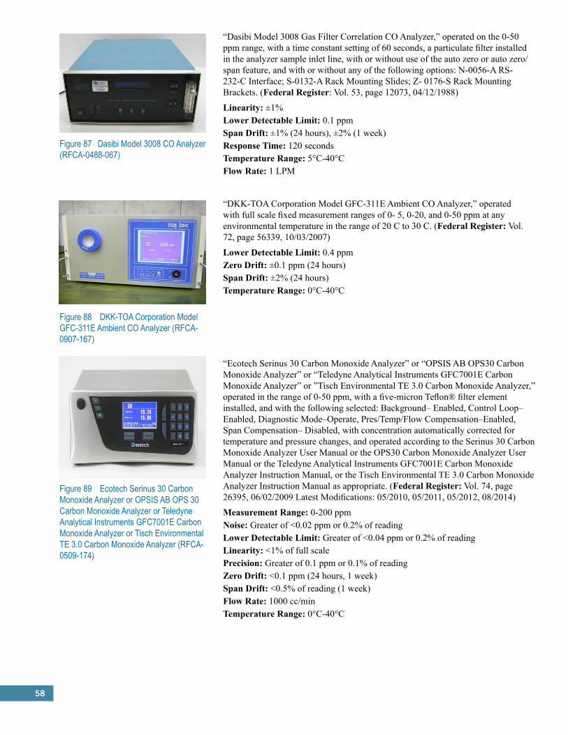
58
Figure 87 Dasibi Model 3008 CO Analyzer (RFCA-0488-067)
“Dasibi Model 3008 Gas Filter Correlation CO Analyzer,” operated on the 0-50 ppm range, with a time constant setting of 60 seconds, a particulate filter installed in the analyzer sample inlet line, with or without use of the auto zero or auto zero/span feature, and with or without any of the following options: N-0056-A RS-232-C Interface; S-0132-A Rack Mounting Slides; Z- 0176-S Rack Mounting Brackets. (Federal Register: Vol. 53, page 12073, 04/12/1988)
Linearity: ±1%Lower Detectable Limit: 0.1 ppmSpan Drift: ±1% (24 hours), ±2% (1 week)Response Time: 120 secondsTemperature Range: 5°C-40°CFlow Rate: 1 LPM
“DKK-TOA Corporation Model GFC-311E Ambient CO Analyzer,” operated with full scale fixed measurement ranges of 0- 5, 0-20, and 0-50 ppm at any environmental temperature in the range of 20 C to 30 C. (Federal Register: Vol. 72, page 56339, 10/03/2007)
Lower Detectable Limit: 0.4 ppmZero Drift: ±0.1 ppm (24 hours)Span Drift: ±2% (24 hours)Temperature Range: 0°C-40°C
Figure 88 DKK-TOA Corporation Model GFC-311E Ambient CO Analyzer (RFCA-0907-167)
Figure 89 Ecotech Serinus 30 Carbon Monoxide Analyzer or OPSIS AB OPS 30 Carbon Monoxide Analyzer or Teledyne Analytical Instruments GFC7001E Carbon Monoxide Analyzer or Tisch Environmental TE 3.0 Carbon Monoxide Analyzer (RFCA-0509-174)
“Ecotech Serinus 30 Carbon Monoxide Analyzer” or “OPSIS AB OPS30 Carbon Monoxide Analyzer” or “Teledyne Analytical Instruments GFC7001E Carbon Monoxide Analyzer” or ”Tisch Environmental TE 3.0 Carbon Monoxide Analyzer,” operated in the range of 0-50 ppm, with a five-micron Teflon® filter element installed, and with the following selected: Background– Enabled, Control Loop–Enabled, Diagnostic Mode–Operate, Pres/Temp/Flow Compensation–Enabled, Span Compensation– Disabled, with concentration automatically corrected for temperature and pressure changes, and operated according to the Serinus 30 Carbon Monoxide Analyzer User Manual or the OPS30 Carbon Monoxide Analyzer User Manual or the Teledyne Analytical Instruments GFC7001E Carbon Monoxide Analyzer Instruction Manual, or the Tisch Environmental TE 3.0 Carbon Monoxide Analyzer Instruction Manual as appropriate. (Federal Register: Vol. 74, page 26395, 06/02/2009 Latest Modifications: 05/2010, 05/2011, 05/2012, 08/2014)
Measurement Range: 0-200 ppmNoise: Greater of <0.02 ppm or 0.2% of readingLower Detectable Limit: Greater of <0.04 ppm or 0.2% of readingLinearity: <1% of full scalePrecision: Greater of 0.1 ppm or 0.1% of readingZero Drift: <0.1 ppm (24 hours, 1 week)Span Drift: <0.5% of reading (1 week)Flow Rate: 1000 cc/minTemperature Range: 0°C-40°C
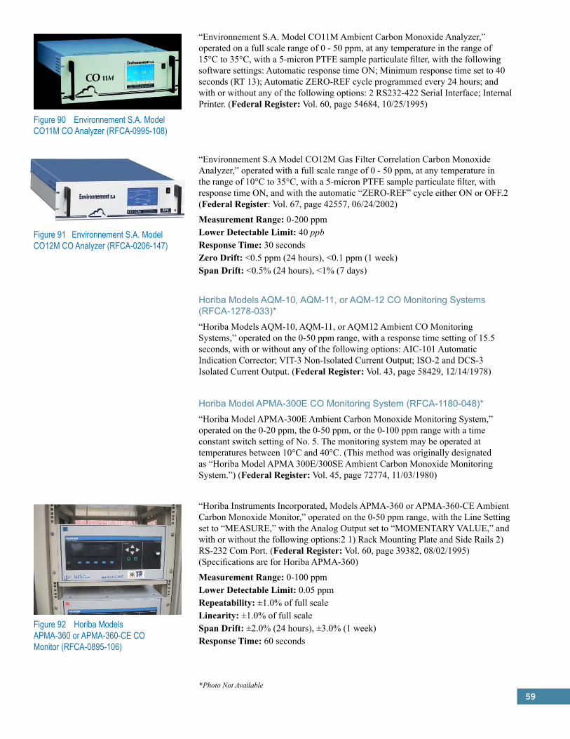
59
Figure 90 Environnement S.A. Model CO11M CO Analyzer (RFCA-0995-108)
“Environnement S.A. Model CO11M Ambient Carbon Monoxide Analyzer,” operated on a full scale range of 0 - 50 ppm, at any temperature in the range of 15°C to 35°C, with a 5-micron PTFE sample particulate filter, with the following software settings: Automatic response time ON; Minimum response time set to 40 seconds (RT 13); Automatic ZERO-REF cycle programmed every 24 hours; and with or without any of the following options: 2 RS232-422 Serial Interface; Internal Printer. (Federal Register: Vol. 60, page 54684, 10/25/1995)
Figure 91 Environnement S.A. Model CO12M CO Analyzer (RFCA-0206-147)
“Environnement S.A Model CO12M Gas Filter Correlation Carbon Monoxide Analyzer,” operated with a full scale range of 0 - 50 ppm, at any temperature in the range of 10°C to 35°C, with a 5-micron PTFE sample particulate filter, with response time ON, and with the automatic “ZERO-REF” cycle either ON or OFF.2 (Federal Register: Vol. 67, page 42557, 06/24/2002)
Measurement Range: 0-200 ppmLower Detectable Limit: 40 ppbResponse Time: 30 secondsZero Drift: <0.5 ppm (24 hours), <0.1 ppm (1 week)Span Drift: <0.5% (24 hours), <1% (7 days)
Horiba Models AQM-10, AQM-11, or AQM-12 CO Monitoring Systems (RFCA-1278-033)*“Horiba Models AQM-10, AQM-11, or AQM12 Ambient CO Monitoring Systems,” operated on the 0-50 ppm range, with a response time setting of 15.5 seconds, with or without any of the following options: AIC-101 Automatic Indication Corrector; VIT-3 Non-Isolated Current Output; ISO-2 and DCS-3 Isolated Current Output. (Federal Register: Vol. 43, page 58429, 12/14/1978)
Horiba Model APMA-300E CO Monitoring System (RFCA-1180-048)*“Horiba Model APMA-300E Ambient Carbon Monoxide Monitoring System,” operated on the 0-20 ppm, the 0-50 ppm, or the 0-100 ppm range with a time constant switch setting of No. 5. The monitoring system may be operated at temperatures between 10°C and 40°C. (This method was originally designated as “Horiba Model APMA 300E/300SE Ambient Carbon Monoxide Monitoring System.”) (Federal Register: Vol. 45, page 72774, 11/03/1980)
“Horiba Instruments Incorporated, Models APMA-360 or APMA-360-CE Ambient Carbon Monoxide Monitor,” operated on the 0-50 ppm range, with the Line Setting set to “MEASURE,” with the Analog Output set to “MOMENTARY VALUE,” and with or without the following options:2 1) Rack Mounting Plate and Side Rails 2) RS-232 Com Port. (Federal Register: Vol. 60, page 39382, 08/02/1995) (Specifications are for Horiba APMA-360)
Measurement Range: 0-100 ppmLower Detectable Limit: 0.05 ppmRepeatability: ±1.0% of full scaleLinearity: ±1.0% of full scaleSpan Drift: ±2.0% (24 hours), ±3.0% (1 week)Response Time: 60 seconds
Figure 92 Horiba Models APMA-360 or APMA-360-CE CO Monitor (RFCA-0895-106)
*Photo Not Available

60
Figure 93 Horiba Model APMA-370 CO Monitor (RFCA-0506-158)
“Horiba Instruments Incorporated Model APMA-370 Ambient CO Monitor,” operated with a full scale fixed measurement range of 0 - 50 ppm, with the automatic range switching off, at any environmental temperature in the range of 20°C to 30°C.2 (Federal Register: Vol. 71, page 25587, 05/01/2006)
Repeatability: ±1.0% of full scaleLinearity: ±1.0% of full scaleFlow Rate: 1.5 LPMMeasurement Range: 0-100 ppm
MASS-CO, Model 1 CO Analyzer (RFCA-1280-050)*“MASS-CO, Model 1 Carbon Monoxide Analyzer,” operated on a range of 0-50 ppm, with automatic zero and span adjustments at time intervals not to exceed 4 hours, with or without the 100 millivolt and 5 volt output options. The method consists of the following components: (1) Infra-2 (Uras 2) Infrared Analyzer Model 5611-200-35, (2) Automatic Calibrator Model 5869-111, (3) Electric Gas Cooler Model 7865-222 or equivalent with pre-humidifier, (4) Diaphragm Pump Model 5861-214 or equivalent, (5) Membrane Filter Model 5862-111 or equivalent, (6) Flow Meter Model SK 1171-U or equivalent, (7) Recorder Model Mini Comp DN 1/192 or equivalent. NOTE: This method is not now commercially available. (Federal Register: Vol. 45, page 81650, 12/11/1980)
Monitor Labs Model 8310 CO Analyzer (RFCA-0979-041)*“Monitor Labs Model 8310 CO Analyzer,” operated on the 0-50 ppm range, with a sample inlet filter, with or without any of the following options: 02A Zero/Span Valves, 03A Floor stand, 04A Pump (60 Hz), 04B Pump (50 Hz), 05A CO Regulator, 06A CO Cylinder, 07A Zero/Span Valve Power Supply, 08A Calibration Valves, 09A, B, C, D Input Power Transformer. (Federal Register: Vol. 44, page 54545, 09/20/1979 and Vol. 45, page 2700, 01/14/1980)
Monitor Labs/Lear Siegler Model 8830 CO Analyzer (RFCA-0388-066)*“Monitor Labs or Lear Siegler Model 8830 CO Analyzer,” operated on the 0-50 ppm range, with a five micron Teflon filter element installed in the rear-panel filter assembly, with or without any of the following options: 2 - Zero/Span Valve Assembly; 3 - Rack Assembly; 4 - Slide Assembly; 7 - 230 VAC, 50/60 Hz. (Federal Register: Vol. 53, page 7233, 03/07/1988)
MSA/LIRA Model 202S CO Analyzer System (RFCA-0177-018)*“LIRA Model 202S Air Quality Carbon Monoxide Analyzer System,” consisting of a LIRA Model 202S optical bench (P/N 459839), a regenerative dryer (P/N 464084), and rack-mounted sampling system; operated on a 0-50 ppm range, with the slow response amplifier, with or without any of the following options: Remote Meter; Remote Zero And Span Controls; 0-1, 5, 20, Or 50 mA Output; 1-5, 4-20, Or 10-50 mA Output; 0-10 Or 100 mV Output; 0-1, 5, Or 10 Volt Output. (Federal Register: Vol. 42, page 5748, 01/31/1977)
*Photo Not Available

61
Figure 94 SIR S.A. Model S-5006 CO Analyzer (RFCA-0708-172)
“SIR S.A. Model S-5006 CO Analyzer” operated with full-scale fixed measurement ranges 0-50 ppm at any environment temperature in the range of 20-30 C (Federal Register: Vol. 73, page 40866, 07/16/2008)
Measurement Range: 0-200 ppmNoise: 0.02 ppmLower Detectable Limit: 0.04 ppmZero Drift: 0.01 ppm (24 hours)Span Drift: 0.5% of full scaleResponse Time: 60 secondsPrecision: ±0.1 ppmLinearity: ±1.0%Temperature Range: 5°C-40°CFlow Rate: 1 LPM
“Teledyne Advanced Pollution Instrumentation Models 300, 300E, 300EU, T300, T300U or Teledyne Monitor Labs, Inc. sensor-e™ Model TML-30, Gas Filter Correlation Carbon Monoxide Analyzer,” operated on any full scale range between 0- 10 ppm and 0-50 ppm (0 - 0.1 ppm for Models 300EU and T300U), at any temperature in the range of 15°C to 35°C for Model 300 or 10°C to 40°C for Models 300E, 300 EU, T300, T300U and TML-30, with a 5-micron TFE filter element or a Kynar® DFU installed in the sample filter assembly, with the dynamic zero and span adjustment set to Off for Model 300, and with or without any of the following options: 2 Option 50, Zero/Span Valves with pressurized span gas and shutoff valve; Option 51, Zero/Span Valves with pressurized span gas and shutoff valve and Internal Zero Air Generator; Option 52, Zero/Span Valves; Option 53, Zero/Span Valves with Internal Zero Air Generator; Rack Mount with slides; RS-232 serial port with status outputs; analog input option; and (for Models 300E, 300EU, T300, T300U and TML-30) 4-20 mA isolated outputs. airpointer® model 801-003000 only: operated on any full scale range between 0-10 ppm and 0-50 ppm, with a PTFE filter element installed in the internal filter assembly, with the software setting: FRM/FEM conform mode; at any temperature in the range of 10°C to 45°C, with either a user- or vendor-supplied vacuum pump capable of providing an absolute pressure of 16 inches mercury or less at 2.5 sLpm; installed in the compact. thermally controlled (-40°C to + 45°C) and weather proof airpointer® base unit with CO List of Designated Reference and Equivalent Methods, June 18, 2015 Page 36 integrated data acquisition and management system mounted on a frame, pole, or wall; with or without wireless telemetry;; with or without internal dilution system with internal span gas bottle; with or without modules for other criteria pollutants; with or without analyzer for particulate matter; with or without additional 3rd party sensors for e.g. meteorology, noise, or traffic counting. Operated with the appropriate instrument manual. Note 2 applies to the following Teledyne Advanced Pollution Instrumentation Models 300E, 300EU, T300, T300U, and Teledyne Monitor Labs, Inc. Sensor-e™ Model TML-30. (Federal Register: Vol. 58, page 58166, 10/29/1993 Latest Modification: 08/2010; 05/2013; 07/2014 (Specifications are for Teledyne Model T300)
Measurement Ranges: 0-1000 ppmZero Noise: <0.02 ppmSpan Noise: <0.5% of readingResponse Time: <60 secondsLinearity: 1.0% of full scalePrecision: 0.5% of readingFlow Rate: 800 cm3/min
Figure 95 Teledyne Advanced Pollution Instrumentation Models 300, 300E, 300EU, T300, T300U or Teledyne Monitor Labs sensor-e™ Model TML-30 CO Analyzer; or recordum airpointer® system module 801-003000 (RFCA-1093-093)
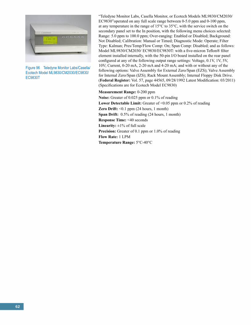
62
Figure 96 Teledyne Monitor Labs/Casella/Ecotech Model ML9830/CM2030/EC9830/EC9830T
“Teledyne Monitor Labs, Casella Monitor, or Ecotech Models ML9830/CM2030/EC9830”operated on any full scale range between 0-5.0 ppm and 0-100 ppm, at any temperature in the range of 15°C to 35°C, with the service switch on the secondary panel set to the In position, with the following menu choices selected: Range: 5.0 ppm to 100.0 ppm; Over-ranging: Enabled or Disabled; Background: Not Disabled; Calibration: Manual or Timed; Diagnostic Mode: Operate; Filter Type: Kalman; Pres/Temp/Flow Comp: On; Span Comp: Disabled; and as follows: Model ML9830/CM2030/ EC9830/EC9830T: with a five-micron Teflon® filter element installed internally, with the 50-pin I/O board installed on the rear panel configured at any of the following output range settings: Voltage, 0.1V, 1V, 5V, 10V; Current, 0-20 mA, 2-20 mA and 4-20 mA; and with or without any of the following options: Valve Assembly for External Zero/Span (EZS); Valve Assembly for Internal Zero/Span (IZS); Rack Mount Assembly; Internal Floppy Disk Drive. (Federal Register: Vol. 57, page 44565, 09/28/1992 Latest Modification: 03/2011) (Specifications are for Ecotech Model EC9830)
Measurement Range: 0-200 ppmNoise: Greater of 0.025 ppm or 0.1% of readingLower Detectable Limit: Greater of <0.05 ppm or 0.2% of readingZero Drift: <0.1 ppm (24 hours, 1 month)Span Drift: 0.5% of reading (24 hours, 1 month)Response Time: <40 secondsLinearity: ±1% of full scalePrecision: Greater of 0.1 ppm or 1.0% of readingFlow Rate: 1 LPMTemperature Range: 5°C-40°C
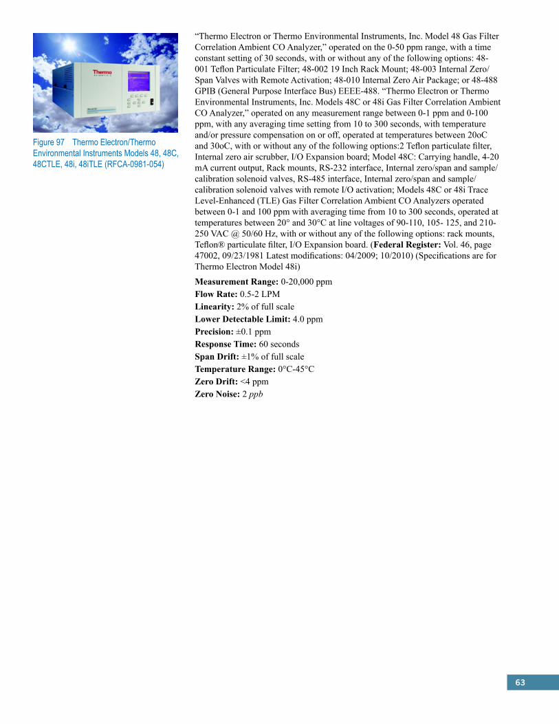
63
Figure 97 Thermo Electron/Thermo Environmental Instruments Models 48, 48C, 48CTLE, 48i, 48iTLE (RFCA-0981-054)
“Thermo Electron or Thermo Environmental Instruments, Inc. Model 48 Gas Filter Correlation Ambient CO Analyzer,” operated on the 0-50 ppm range, with a time constant setting of 30 seconds, with or without any of the following options: 48-001 Teflon Particulate Filter; 48-002 19 Inch Rack Mount; 48-003 Internal Zero/Span Valves with Remote Activation; 48-010 Internal Zero Air Package; or 48-488 GPIB (General Purpose Interface Bus) EEEE-488. “Thermo Electron or Thermo Environmental Instruments, Inc. Models 48C or 48i Gas Filter Correlation Ambient CO Analyzer,” operated on any measurement range between 0-1 ppm and 0-100 ppm, with any averaging time setting from 10 to 300 seconds, with temperature and/or pressure compensation on or off, operated at temperatures between 20oC and 30oC, with or without any of the following options:2 Teflon particulate filter, Internal zero air scrubber, I/O Expansion board; Model 48C: Carrying handle, 4-20 mA current output, Rack mounts, RS-232 interface, Internal zero/span and sample/calibration solenoid valves, RS-485 interface, Internal zero/span and sample/calibration solenoid valves with remote I/O activation; Models 48C or 48i Trace Level-Enhanced (TLE) Gas Filter Correlation Ambient CO Analyzers operated between 0-1 and 100 ppm with averaging time from 10 to 300 seconds, operated at temperatures between 20° and 30°C at line voltages of 90-110, 105- 125, and 210-250 VAC @ 50/60 Hz, with or without any of the following options: rack mounts, Teflon® particulate filter, I/O Expansion board. (Federal Register: Vol. 46, page 47002, 09/23/1981 Latest modifications: 04/2009; 10/2010) (Specifications are for Thermo Electron Model 48i)
Measurement Range: 0-20,000 ppmFlow Rate: 0.5-2 LPMLinearity: 2% of full scaleLower Detectable Limit: 4.0 ppmPrecision: ±0.1 ppmResponse Time: 60 secondsSpan Drift: ±1% of full scaleTemperature Range: 0°C-45°CZero Drift: <4 ppmZero Noise: 2 ppb
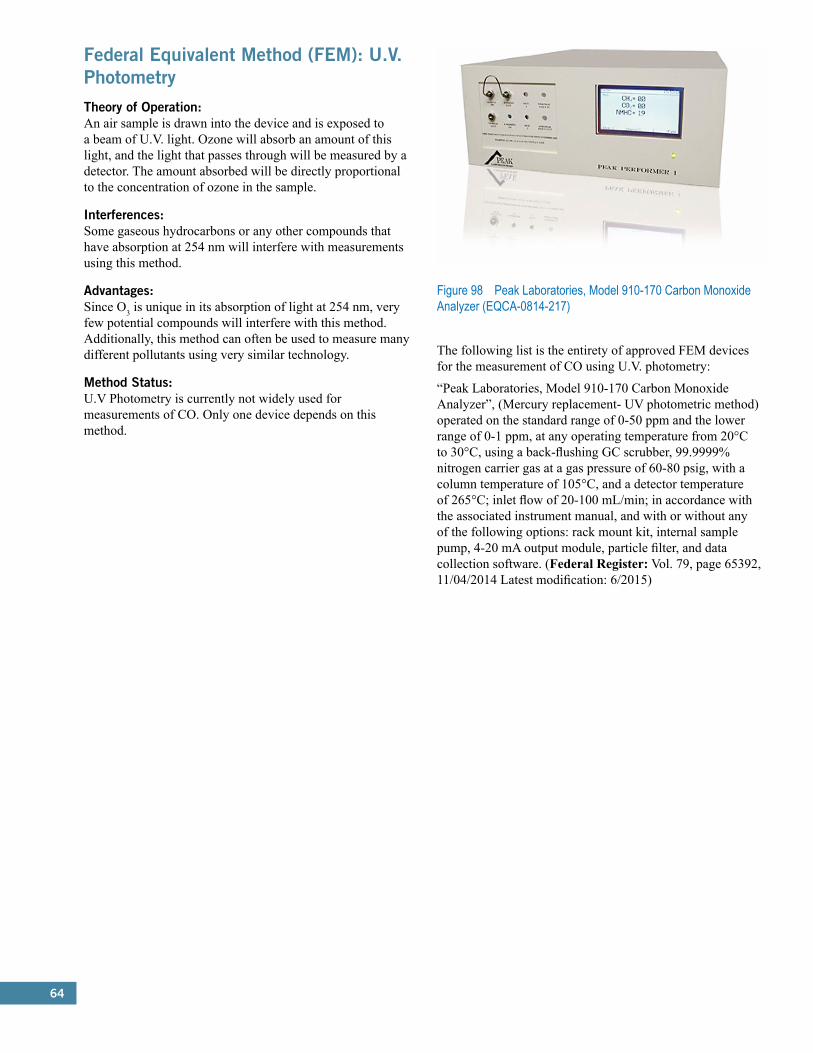
64
Federal Equivalent Method (FEM): U.V. PhotometryTheory of Operation:An air sample is drawn into the device and is exposed to a beam of U.V. light. Ozone will absorb an amount of this light, and the light that passes through will be measured by a detector. The amount absorbed will be directly proportional to the concentration of ozone in the sample.
Interferences:Some gaseous hydrocarbons or any other compounds that have absorption at 254 nm will interfere with measurements using this method.
Advantages:Since O3 is unique in its absorption of light at 254 nm, very few potential compounds will interfere with this method. Additionally, this method can often be used to measure many different pollutants using very similar technology.
Method Status:U.V Photometry is currently not widely used for measurements of CO. Only one device depends on this method.
Figure 98 Peak Laboratories, Model 910-170 Carbon Monoxide Analyzer (EQCA-0814-217)
The following list is the entirety of approved FEM devices for the measurement of CO using U.V. photometry:
“Peak Laboratories, Model 910-170 Carbon Monoxide Analyzer”, (Mercury replacement- UV photometric method) operated on the standard range of 0-50 ppm and the lower range of 0-1 ppm, at any operating temperature from 20°C to 30°C, using a back-flushing GC scrubber, 99.9999% nitrogen carrier gas at a gas pressure of 60-80 psig, with a column temperature of 105°C, and a detector temperature of 265°C; inlet flow of 20-100 mL/min; in accordance with the associated instrument manual, and with or without any of the following options: rack mount kit, internal sample pump, 4-20 mA output module, particle filter, and data collection software. (Federal Register: Vol. 79, page 65392, 11/04/2014 Latest modification: 6/2015)
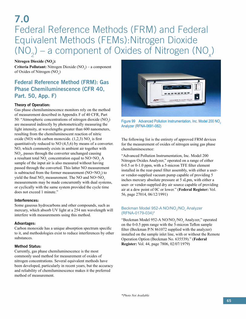
65
Nitrogen Dioxide (NO2):Criteria Pollutant: Nitrogen Dioxide (NO2) – a component of Oxides of Nitrogen (NOx)
Federal Reference Method (FRM): Gas Phase Chemiluminescence (CFR 40, Part. 50, App. F)Theory of Operation:Gas phase chemiluminescence monitors rely on the method of measurement described in Appendix F of 40 CFR, Part 50: “Atmospheric concentrations of nitrogen dioxide (NO2) are measured indirectly by photometrically measuring the light intensity, at wavelengths greater than 600 nanometers, resulting from the chemiluminescent reaction of nitric oxide (NO) with carbon monoxide. (1,2,3) NO2 is first quantitatively reduced to NO (4,5,6) by means of a converter. NO, which commonly exists in ambient air together with NO2, passes through the converter unchanged causing a resultant total NOx concentration equal to NO+NO2. A sample of the input air is also measured without having passed through the converted. This latter NO measurement is subtracted from the former measurement (NO+NO2) to yield the final NO2 measurement. The NO and NO+NO2 measurements may be made concurrently with dual systems, or cyclically with the same system provided the cycle time does not exceed 1 minute.”
Interferences:Some gaseous hydrocarbons and other compounds, such as mercury, which absorb UV light at a 254 nm wavelength will interfere with measurements using this method.
Advantages:Carbon monoxide has a unique absorption spectrum specific to it, and methodologies exist to reduce interferences by other substances.
Method Status:Currently, gas phase chemiluminescence is the most commonly used method for measurement of oxides of nitrogen concentrations. Several equivalent methods have been developed, particularly in recent years, but the accuracy and reliability of chemiluminescence makes it the preferred method of measurement.
Figure 99 Advanced Pollution Instrumentation, Inc. Model 200 NO2 Analyzer (RFNA-0691-082)
The following list is the entirety of approved FRM devices for the measurement of oxides of nitrogen using gas phase chemiluminescence:
“Advanced Pollution Instrumentation, Inc. Model 200 Nitrogen Oxides Analyzer,” operated on a range of either 0-0.5 or 0-1.0 ppm, with a 5-micron TFE filter element installed in the rear-panel filter assembly, with either a user- or vendor-supplied vacuum pump capable of providing 5 inches mercury absolute pressure at 5 sLpm, with either a user- or vendor-supplied dry air source capable of providing air at a dew point of 0C or lower.” (Federal Register: Vol. 56, page 27014, 06/12/1991)
Beckman Model 952-A NO/NO2/NOx Analyzer (RFNA-0179-034)*“Beckman Model 952-A NO/NO2/NOx Analyzer,” operated on the 0-0.5 ppm range with the 5-micron Teflon sample filter (Beckman P/N 861072 supplied with the analyzer) installed on the sample inlet line, with or without the Remote Operation Option (Beckman No. 635539).” (Federal Register: Vol. 44, page 7806, 02/07/1979)
7.0 Federal Reference Methods (FRM) and Federal Equivalent Methods (FEMs):Nitrogen Dioxide (NO2) – a component of Oxides of Nitrogen (NOx)
*Photo Not Available
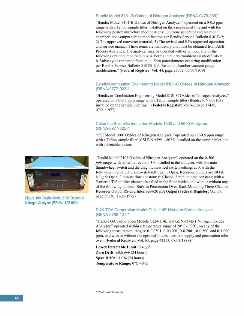
66
Bendix Model 8101-B Oxides of Nitrogen Analyzer (RFNA-0479-038)*“Bendix Model 8101-B Oxides of Nitrogen Analyzer,” operated on a 0-0.5 ppm range with a Teflon sample filter installed on the sample inlet line and with the following post-manufacture modifications: 1) Ozone generator and reaction chamber input-output tubing modification per Bendix Service Bulletin 8101B-2; 2) The approved converter material; 3) The revised and EPA approved operation and service manual. These items are mandatory and must be obtained from ABB Process Analytics. The analyzer may be operated with or without any of the following optional modifications: a. Perma Pure dryer/ambient air modification; b. Valve cycle time modification; c. Zero potentiometer centering modification per Bendix Service Bulletin 8101B-1; d. Reaction chamber vacuum gauge modification.” (Federal Register: Vol. 44, page 26792, 05/07/1979)
Bendix/Combustion Engineering Model 8101-C Oxides of Nitrogen Analyzer (RFNA-0777-022)*“Bendix or Combustion Engineering Model 8101-C Oxides of Nitrogen Analyzer,” operated on a 0-0.5 ppm range with a Teflon sample filter (Bendix P/N 007163) installed on the sample inlet line.” (Federal Register: Vol. 42, page 37435, 07/21/1977)
Columbia Scientific Industries Models 1600 and 5600 Analyzers (RFNA-0977-025)*“CSI Model 1600 Oxides of Nitrogen Analyzer,” operated on a 0-0.5 ppm range with a Teflon sample filter (CSI P/N M951- 8023) installed on the sample inlet line, with selectable options.
“Dasibi Model 2108 Oxides of Nitrogen Analyzer,” operated on the 0-500 ppb range, with software revision 3.6 installed in the analyzer, with the auto thumbwheel switch and the diag thumbwheel switch settings at 0, with the following internal CPU dipswitch settings: 1: Open, Recorder outputs are NO & NO2; 5: Open, 3 minute time constant; 6: Closed, 3 minute time constant; with a 5-micron Teflon filter element installed in the filter holder, and with or without any of the following options: Built-in Permeation Oven Rack Mounting Three-Channel Recorder Output RS-232 Interface4-20 mA Output (Federal Register: Vol. 57, page 55530, 11/25/1992)
DKK-TOA Corporation Model GLN-114E Nitrogen Oxides Analyzer (RFNA-0798-121)*“DKK-TOA Corporation Models GLN-114E and GLN-114E-1 Nitrogen Oxides Analyzer,” operated within a temperature range of 20°C - 30°C, on any of the following measurement ranges: 0-0.0501, 0-0.1001, 0-0.2001, 0-0.500, and 0-1.000 ppm, and with or without the optional Internal zero air supply and permeation tube oven. (Federal Register: Vol. 63, page 41253, 08/03/1998)
Lower Detectable Limit: 0.4 ppbZero Drift: ±0.6 ppb (24 hours)Span Drift: ±1.0% (24 hours)Temperature Range: 0°C-40°C
Figure 100 Dasibi Model 2108 Oxides of Nitrogen Analyzer (RFNA-1192-089)
*Photo Not Available
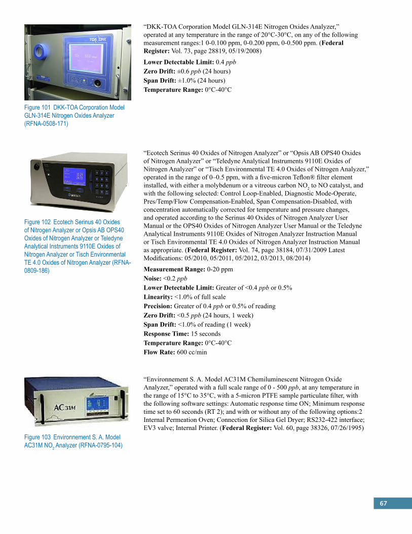
67
Figure 101 DKK-TOA Corporation Model GLN-314E Nitrogen Oxides Analyzer (RFNA-0508-171)
“DKK-TOA Corporation Model GLN-314E Nitrogen Oxides Analyzer,” operated at any temperature in the range of 20°C-30°C, on any of the following measurement ranges:1 0-0.100 ppm, 0-0.200 ppm, 0-0.500 ppm. (Federal Register: Vol. 73, page 28819, 05/19/2008)
Lower Detectable Limit: 0.4 ppbZero Drift: ±0.6 ppb (24 hours)Span Drift: ±1.0% (24 hours)Temperature Range: 0°C-40°C
Figure 102 Ecotech Serinus 40 Oxides of Nitrogen Analyzer or Opsis AB OPS40 Oxides of Nitrogen Analyzer or Teledyne Analytical Instruments 9110E Oxides of Nitrogen Analyzer or Tisch Environmental TE 4.0 Oxides of Nitrogen Analyzer (RFNA-0809-186)
“Ecotech Serinus 40 Oxides of Nitrogen Analyzer” or “Opsis AB OPS40 Oxides of Nitrogen Analyzer” or “Teledyne Analytical Instruments 9110E Oxides of Nitrogen Analyzer” or “Tisch Environmental TE 4.0 Oxides of Nitrogen Analyzer,” operated in the range of 0–0.5 ppm, with a five-micron Teflon® filter element installed, with either a molybdenum or a vitreous carbon NO2 to NO catalyst, and with the following selected: Control Loop-Enabled, Diagnostic Mode-Operate, Pres/Temp/Flow Compensation-Enabled, Span Compensation-Disabled, with concentration automatically corrected for temperature and pressure changes, and operated according to the Serinus 40 Oxides of Nitrogen Analyzer User Manual or the OPS40 Oxides of Nitrogen Analyzer User Manual or the Teledyne Analytical Instruments 9110E Oxides of Nitrogen Analyzer Instruction Manual or Tisch Environmental TE 4.0 Oxides of Nitrogen Analyzer Instruction Manual as appropriate. (Federal Register: Vol. 74, page 38184, 07/31/2009 Latest Modifications: 05/2010, 05/2011, 05/2012, 03/2013, 08/2014)
Measurement Range: 0-20 ppmNoise: <0.2 ppbLower Detectable Limit: Greater of <0.4 ppb or 0.5%Linearity: <1.0% of full scalePrecision: Greater of 0.4 ppb or 0.5% of readingZero Drift: <0.5 ppb (24 hours, 1 week)Span Drift: <1.0% of reading (1 week)Response Time: 15 secondsTemperature Range: 0°C-40°CFlow Rate: 600 cc/min
Figure 103 Environnement S. A. Model AC31M NO2 Analyzer (RFNA-0795-104)
“Environnement S. A. Model AC31M Chemiluminescent Nitrogen Oxide Analyzer,” operated with a full scale range of 0 - 500 ppb, at any temperature in the range of 15°C to 35°C, with a 5-micron PTFE sample particulate filter, with the following software settings: Automatic response time ON; Minimum response time set to 60 seconds (RT 2); and with or without any of the following options:2 Internal Permeation Oven; Connection for Silica Gel Dryer; RS232-422 interface; EV3 valve; Internal Printer. (Federal Register: Vol. 60, page 38326, 07/26/1995)
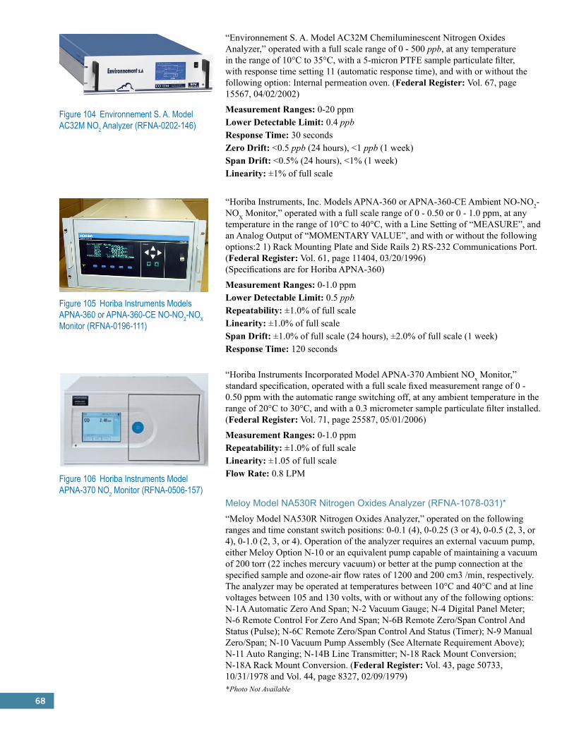
68
Figure 104 Environnement S. A. Model AC32M NO2 Analyzer (RFNA-0202-146)
“Environnement S. A. Model AC32M Chemiluminescent Nitrogen Oxides Analyzer,” operated with a full scale range of 0 - 500 ppb, at any temperature in the range of 10°C to 35°C, with a 5-micron PTFE sample particulate filter, with response time setting 11 (automatic response time), and with or without the following option: Internal permeation oven. (Federal Register: Vol. 67, page 15567, 04/02/2002)
Measurement Ranges: 0-20 ppmLower Detectable Limit: 0.4 ppbResponse Time: 30 secondsZero Drift: <0.5 ppb (24 hours), <1 ppb (1 week)Span Drift: <0.5% (24 hours), <1% (1 week)Linearity: ±1% of full scale
“Horiba Instruments, Inc. Models APNA-360 or APNA-360-CE Ambient NO-NO2-NOX Monitor,” operated with a full scale range of 0 - 0.50 or 0 - 1.0 ppm, at any temperature in the range of 10°C to 40°C, with a Line Setting of “MEASURE”, and an Analog Output of “MOMENTARY VALUE”, and with or without the following options:2 1) Rack Mounting Plate and Side Rails 2) RS-232 Communications Port. (Federal Register: Vol. 61, page 11404, 03/20/1996) (Specifications are for Horiba APNA-360)
Measurement Ranges: 0-1.0 ppmLower Detectable Limit: 0.5 ppbRepeatability: ±1.0% of full scaleLinearity: ±1.0% of full scaleSpan Drift: ±1.0% of full scale (24 hours), ±2.0% of full scale (1 week)Response Time: 120 seconds
“Horiba Instruments Incorporated Model APNA-370 Ambient NOx Monitor,” standard specification, operated with a full scale fixed measurement range of 0 - 0.50 ppm with the automatic range switching off, at any ambient temperature in the range of 20°C to 30°C, and with a 0.3 micrometer sample particulate filter installed. (Federal Register: Vol. 71, page 25587, 05/01/2006)
Measurement Ranges: 0-1.0 ppmRepeatability: ±1.0% of full scaleLinearity: ±1.05 of full scaleFlow Rate: 0.8 LPM
Meloy Model NA530R Nitrogen Oxides Analyzer (RFNA-1078-031)*“Meloy Model NA530R Nitrogen Oxides Analyzer,” operated on the following ranges and time constant switch positions: 0-0.1 (4), 0-0.25 (3 or 4), 0-0.5 (2, 3, or 4), 0-1.0 (2, 3, or 4). Operation of the analyzer requires an external vacuum pump, either Meloy Option N-10 or an equivalent pump capable of maintaining a vacuum of 200 torr (22 inches mercury vacuum) or better at the pump connection at the specified sample and ozone-air flow rates of 1200 and 200 cm3 /min, respectively. The analyzer may be operated at temperatures between 10°C and 40°C and at line voltages between 105 and 130 volts, with or without any of the following options: N-1A Automatic Zero And Span; N-2 Vacuum Gauge; N-4 Digital Panel Meter; N-6 Remote Control For Zero And Span; N-6B Remote Zero/Span Control And Status (Pulse); N-6C Remote Zero/Span Control And Status (Timer); N-9 Manual Zero/Span; N-10 Vacuum Pump Assembly (See Alternate Requirement Above); N-11 Auto Ranging; N-14B Line Transmitter; N-18 Rack Mount Conversion; N-18A Rack Mount Conversion. (Federal Register: Vol. 43, page 50733, 10/31/1978 and Vol. 44, page 8327, 02/09/1979)
Figure 105 Horiba Instruments Models APNA-360 or APNA-360-CE NO-NO2-NOX Monitor (RFNA-0196-111)
Figure 106 Horiba Instruments Model APNA-370 NO2 Monitor (RFNA-0506-157)
*Photo Not Available

69
Monitor Labs Model 8440E Nitrogen Oxides Analyzer (RFNA-0677-021)*“Monitor Labs Model 8440E Nitrogen Oxides Analyzer,” operated on a 0-0.5 ppm range (position 2 of range switch) with a time constant setting of 20 seconds, with or without any of the following options: TF- Sample Particulate Filter, DO- Status Outputs, 018A- Ozone Dry Air, O18B- Ozone Dry Air - No Drierite, R- Rack Mount, V- Zero/Span Valves, FM- Flow meters. (Federal Register: Vol. 42, page 37434, 07/21/1977; Vol. 42, page 46575, 09/16/1977; Vol. 46, page 29986, 06/04/1981)
Monitor Labs/Lear Siegler Model 8840 Nitrogen Oxides Analyzer (RFNA-0280-042)*“Monitor Labs or Lear Siegler Model 8840 Nitrogen Oxides Analyzer,” operated on a range of either 0-0.5 or 0-1.0 ppm, with an internal time constant setting of 60 seconds, a TFE sample filter installed on the sample inlet line, with or without any of the following options: 02 Flowmeter, 08A Pump Pac Assembly with 09A (115 VAC), 011A Recorder Output 1 Volt 03A Rack Ears, 08B Pump Pac Assembly with 09B (100 VAC), 011B Recorder Output 100 mV 03B Slides, 08C Pump Pac Assembly with 09C (220/240 VAC), 011C Recorder Output 10 mV, 05A Zero/Span Valves, 08D Rack Mount Panel Assembly, 012A DAS Output 1 Volt, 05B Valve/Relay, 09A Pump 115 VAC 50/60 Hz, 012B DAS Output 100 mV, 06 Status, 09B Pump 100 VAC 50/60 Hz 012C DAS Output 10 mV, 07A Input Power Transformer 100 VAC, 50/60 Hz 09C Pump 220/240 VAC 50 Hz, 013A Ozone Dry Air, 07B Input Power Transformer 220/240 VAC 50 Hz, 013B Ozone Dry Air - No Drierite. (Federal Register: Vol. 45, page 9100, 02/11/1980 and Vol. 46, page 29986, 06/04/1981)
Monitor Labs/Lear Siegler Model 8841 Nitrogen Oxides Analyzer (RFNA-0991-083)*“Monitor Labs or Lear Siegler Model 8841 Nitrogen Oxides Analyzer,” operated on the 0-0.05 ppm, 1 0-0.1 ppm, 1 0-0.2 ppm, 1 0 - 0.5 ppm, or 0-1.0 ppm range, with manufacturer-supplied vacuum pump or alternative user-supplied vacuum pump capable of providing 200 torr or better absolute vacuum while operating with the analyzer. (Federal Register: Vol. 56, page 47473, 09/19/1991)
Philips Model PW9762/02 NO/NO2/NOx Analyzer (RFNA-0879-040)*“Philips Model PW9762/02 NO/NO2/NOx Analyzer,” consisting of the following components: PW9762/02 Basic Analyzer; PW9729/00 Converter Cartridge; PW9731/00 Sampler or PW9731/20 Dust Filter; operated on a range of 0-0.5 ppm, with or without any of the following accessories: PW9752/00 Air Sampler Manifold; PW9732/00 Sample Line Heater; PW9011/00 Remote Control Set. (Federal Register: Vol. 44, page 51683, 09/04/1979)
“Seres Model NOx 2000 G Nitrogen Dioxide Ambient Air Analyzer,” operated with a full-scale measurement range of 1 - 0.50 ppm, at any ambient temperature in the range of 20°C-30°C. (Federal Register: Vol. 71, page 42089, 07/25/2006)
Figure 107 Seres Model NOx 2000 G Nitrogen Dioxide Analyzer (RFNA-0706-163)
*Photo Not Available
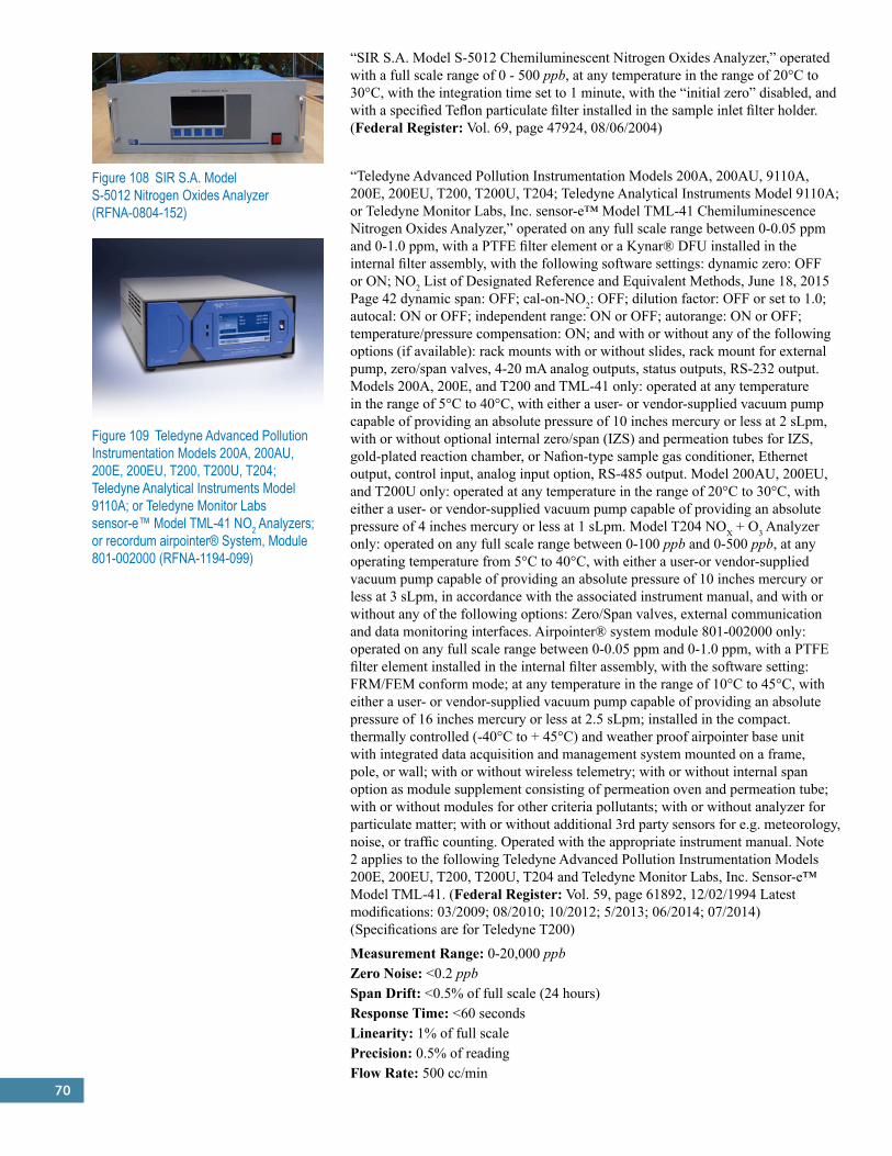
70
Figure 108 SIR S.A. Model S-5012 Nitrogen Oxides Analyzer (RFNA-0804-152)
“SIR S.A. Model S-5012 Chemiluminescent Nitrogen Oxides Analyzer,” operated with a full scale range of 0 - 500 ppb, at any temperature in the range of 20°C to 30°C, with the integration time set to 1 minute, with the “initial zero” disabled, and with a specified Teflon particulate filter installed in the sample inlet filter holder. (Federal Register: Vol. 69, page 47924, 08/06/2004)
“Teledyne Advanced Pollution Instrumentation Models 200A, 200AU, 9110A, 200E, 200EU, T200, T200U, T204; Teledyne Analytical Instruments Model 9110A; or Teledyne Monitor Labs, Inc. sensor-e™ Model TML-41 Chemiluminescence Nitrogen Oxides Analyzer,” operated on any full scale range between 0-0.05 ppm and 0-1.0 ppm, with a PTFE filter element or a Kynar® DFU installed in the internal filter assembly, with the following software settings: dynamic zero: OFF or ON; NO2 List of Designated Reference and Equivalent Methods, June 18, 2015 Page 42 dynamic span: OFF; cal-on-NO2: OFF; dilution factor: OFF or set to 1.0; autocal: ON or OFF; independent range: ON or OFF; autorange: ON or OFF; temperature/pressure compensation: ON; and with or without any of the following options (if available): rack mounts with or without slides, rack mount for external pump, zero/span valves, 4-20 mA analog outputs, status outputs, RS-232 output. Models 200A, 200E, and T200 and TML-41 only: operated at any temperature in the range of 5°C to 40°C, with either a user- or vendor-supplied vacuum pump capable of providing an absolute pressure of 10 inches mercury or less at 2 sLpm, with or without optional internal zero/span (IZS) and permeation tubes for IZS, gold-plated reaction chamber, or Nafion-type sample gas conditioner, Ethernet output, control input, analog input option, RS-485 output. Model 200AU, 200EU, and T200U only: operated at any temperature in the range of 20°C to 30°C, with either a user- or vendor-supplied vacuum pump capable of providing an absolute pressure of 4 inches mercury or less at 1 sLpm. Model T204 NOX + O3 Analyzer only: operated on any full scale range between 0-100 ppb and 0-500 ppb, at any operating temperature from 5°C to 40°C, with either a user-or vendor-supplied vacuum pump capable of providing an absolute pressure of 10 inches mercury or less at 3 sLpm, in accordance with the associated instrument manual, and with or without any of the following options: Zero/Span valves, external communication and data monitoring interfaces. Airpointer® system module 801-002000 only: operated on any full scale range between 0-0.05 ppm and 0-1.0 ppm, with a PTFE filter element installed in the internal filter assembly, with the software setting: FRM/FEM conform mode; at any temperature in the range of 10°C to 45°C, with either a user- or vendor-supplied vacuum pump capable of providing an absolute pressure of 16 inches mercury or less at 2.5 sLpm; installed in the compact. thermally controlled (-40°C to + 45°C) and weather proof airpointer base unit with integrated data acquisition and management system mounted on a frame, pole, or wall; with or without wireless telemetry; with or without internal span option as module supplement consisting of permeation oven and permeation tube; with or without modules for other criteria pollutants; with or without analyzer for particulate matter; with or without additional 3rd party sensors for e.g. meteorology, noise, or traffic counting. Operated with the appropriate instrument manual. Note 2 applies to the following Teledyne Advanced Pollution Instrumentation Models 200E, 200EU, T200, T200U, T204 and Teledyne Monitor Labs, Inc. Sensor-e™ Model TML-41. (Federal Register: Vol. 59, page 61892, 12/02/1994 Latest modifications: 03/2009; 08/2010; 10/2012; 5/2013; 06/2014; 07/2014) (Specifications are for Teledyne T200)
Measurement Range: 0-20,000 ppbZero Noise: <0.2 ppbSpan Drift: <0.5% of full scale (24 hours)Response Time: <60 secondsLinearity: 1% of full scalePrecision: 0.5% of readingFlow Rate: 500 cc/min
Figure 109 Teledyne Advanced Pollution Instrumentation Models 200A, 200AU, 200E, 200EU, T200, T200U, T204; Teledyne Analytical Instruments Model 9110A; or Teledyne Monitor Labs sensor-e™ Model TML-41 NO2 Analyzers; or recordum airpointer® System, Module 801-002000 (RFNA-1194-099)
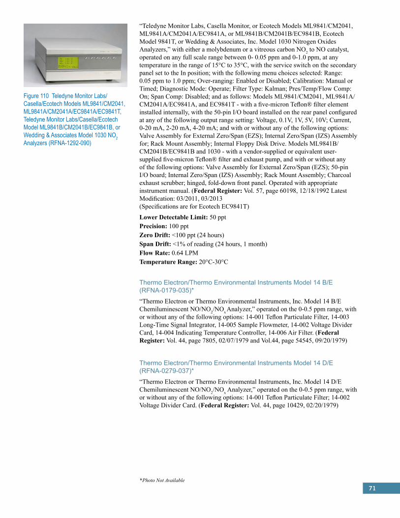
71
“Teledyne Monitor Labs, Casella Monitor, or Ecotech Models ML9841/CM2041, ML9841A/CM2041A/EC9841A, or ML9841B/CM2041B/EC9841B, Ecotech Model 9841T, or Wedding & Associates, Inc. Model 1030 Nitrogen Oxides Analyzers,” with either a molybdenum or a vitreous carbon NO2 to NO catalyst, operated on any full scale range between 0- 0.05 ppm and 0-1.0 ppm, at any temperature in the range of 15°C to 35°C, with the service switch on the secondary panel set to the In position; with the following menu choices selected: Range: 0.05 ppm to 1.0 ppm; Over-ranging: Enabled or Disabled; Calibration: Manual or Timed; Diagnostic Mode: Operate; Filter Type: Kalman; Pres/Temp/Flow Comp: On; Span Comp: Disabled; and as follows: Models ML9841/CM2041, ML9841A/CM2041A/EC9841A, and EC9841T - with a five-micron Teflon® filter element installed internally, with the 50-pin I/O board installed on the rear panel configured at any of the following output range setting: Voltage, 0.1V, 1V, 5V, 10V; Current, 0-20 mA, 2-20 mA, 4-20 mA; and with or without any of the following options: Valve Assembly for External Zero/Span (EZS); Internal Zero/Span (IZS) Assembly for; Rack Mount Assembly; Internal Floppy Disk Drive. Models ML9841B/CM2041B/EC9841B and 1030 - with a vendor-supplied or equivalent user-supplied five-micron Teflon® filter and exhaust pump, and with or without any of the following options: Valve Assembly for External Zero/Span (EZS); 50-pin I/O board; Internal Zero/Span (IZS) Assembly; Rack Mount Assembly; Charcoal exhaust scrubber; hinged, fold-down front panel. Operated with appropriate instrument manual. (Federal Register: Vol. 57, page 60198, 12/18/1992 Latest Modification: 03/2011, 03/2013 (Specifications are for Ecotech EC9841T)
Lower Detectable Limit: 50 pptPrecision: 100 pptZero Drift: <100 ppt (24 hours)Span Drift: <1% of reading (24 hours, 1 month)Flow Rate: 0.64 LPMTemperature Range: 20°C-30°C
Thermo Electron/Thermo Environmental Instruments Model 14 B/E (RFNA-0179-035)*“Thermo Electron or Thermo Environmental Instruments, Inc. Model 14 B/E Chemiluminescent NO/NO2/NOx Analyzer,” operated on the 0-0.5 ppm range, with or without any of the following options: 14-001 Teflon Particulate Filter, 14-003 Long-Time Signal Integrator, 14-005 Sample Flowmeter, 14-002 Voltage Divider Card, 14-004 Indicating Temperature Controller, 14-006 Air Filter. (Federal Register: Vol. 44, page 7805, 02/07/1979 and Vol.44, page 54545, 09/20/1979)
Thermo Electron/Thermo Environmental Instruments Model 14 D/E (RFNA-0279-037)*“Thermo Electron or Thermo Environmental Instruments, Inc. Model 14 D/E Chemiluminescent NO/NO2/NOx Analyzer,” operated on the 0-0.5 ppm range, with or without any of the following options: 14-001 Teflon Particulate Filter; 14-002 Voltage Divider Card. (Federal Register: Vol. 44, page 10429, 02/20/1979)
Figure 110 Teledyne Monitor Labs/Casella/Ecotech Models ML9841/CM2041, ML9841A/CM2041A/EC9841A/EC9841T, Teledyne Monitor Labs/Casella/Ecotech Model ML9841B/CM2041B/EC9841B, or Wedding & Associates Model 1030 NO2 Analyzers (RFNA-1292-090)
*Photo Not Available
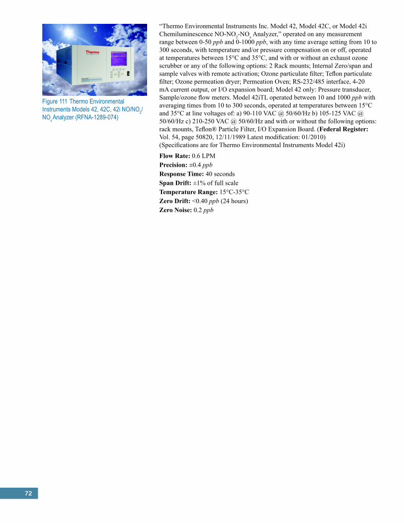
72
Figure 111 Thermo Environmental Instruments Models 42, 42C, 42i NO/NO2/NOx Analyzer (RFNA-1289-074)
“Thermo Environmental Instruments Inc. Model 42, Model 42C, or Model 42i Chemiluminescence NO-NO2-NOx Analyzer,” operated on any measurement range between 0-50 ppb and 0-1000 ppb, with any time average setting from 10 to 300 seconds, with temperature and/or pressure compensation on or off, operated at temperatures between 15°C and 35°C, and with or without an exhaust ozone scrubber or any of the following options: 2 Rack mounts; Internal Zero/span and sample valves with remote activation; Ozone particulate filter; Teflon particulate filter; Ozone permeation dryer; Permeation Oven; RS-232/485 interface, 4-20 mA current output, or I/O expansion board; Model 42 only: Pressure transducer, Sample/ozone flow meters. Model 42iTL operated between 10 and 1000 ppb with averaging times from 10 to 300 seconds, operated at temperatures between 15°C and 35°C at line voltages of: a) 90-110 VAC @ 50/60/Hz b) 105-125 VAC @ 50/60/Hz c) 210-250 VAC @ 50/60/Hz and with or without the following options: rack mounts, Teflon® Particle Filter, I/O Expansion Board. (Federal Register: Vol. 54, page 50820, 12/11/1989 Latest modification: 01/2010) (Specifications are for Thermo Environmental Instruments Model 42i)
Flow Rate: 0.6 LPMPrecision: ±0.4 ppbResponse Time: 40 secondsSpan Drift: ±1% of full scaleTemperature Range: 15°C-35°CZero Drift: <0.40 ppb (24 hours)Zero Noise: 0.2 ppb
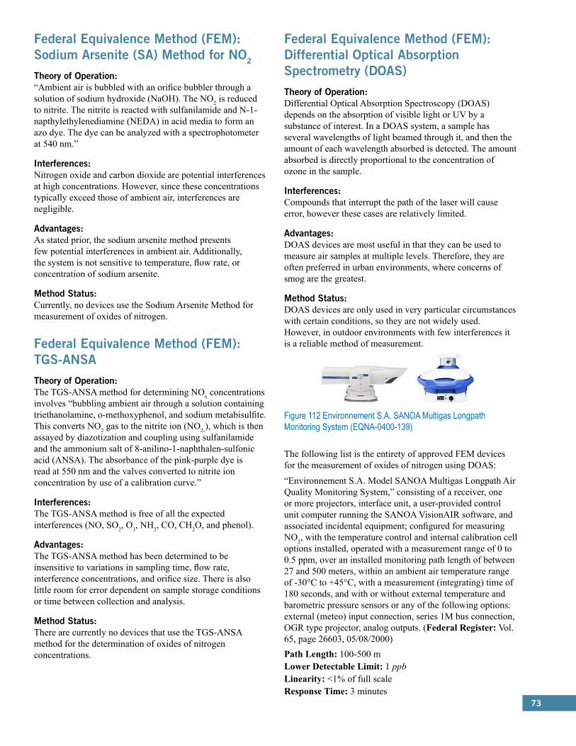
73
Federal Equivalence Method (FEM): Sodium Arsenite (SA) Method for NO2
Theory of Operation:“Ambient air is bubbled with an orifice bubbler through a solution of sodium hydroxide (NaOH). The NO2 is reduced to nitrite. The nitrite is reacted with sulfanilamide and N-1- napthylethylenediamine (NEDA) in acid media to form an azo dye. The dye can be analyzed with a spectrophotometer at 540 nm.”
Interferences:Nitrogen oxide and carbon dioxide are potential interferences at high concentrations. However, since these concentrations typically exceed those of ambient air, interferences are negligible.
Advantages:As stated prior, the sodium arsenite method presents few potential interferences in ambient air. Additionally, the system is not sensitive to temperature, flow rate, or concentration of sodium arsenite.
Method Status:Currently, no devices use the Sodium Arsenite Method for measurement of oxides of nitrogen.
Federal Equivalence Method (FEM): TGS-ANSATheory of Operation:The TGS-ANSA method for determining NOx concentrations involves “bubbling ambient air through a solution containing triethanolamine, o-methoxyphenol, and sodium metabisulfite. This converts NO2 gas to the nitrite ion (NO2-), which is then assayed by diazotization and coupling using sulfanilamide and the ammonium salt of 8-anilino-1-naphthalen-sulfonic acid (ANSA). The absorbance of the pink-purple dye is read at 550 nm and the valves converted to nitrite ion concentration by use of a calibration curve.”
Interferences:The TGS-ANSA method is free of all the expected interferences (NO, SO2, O3, NH3, CO, CH2O, and phenol).
Advantages:The TGS-ANSA method has been determined to be insensitive to variations in sampling time, flow rate, interference concentrations, and orifice size. There is also little room for error dependent on sample storage conditions or time between collection and analysis.
Method Status:There are currently no devices that use the TGS-ANSA method for the determination of oxides of nitrogen concentrations.
Federal Equivalence Method (FEM): Differential Optical Absorption Spectrometry (DOAS)Theory of Operation:Differential Optical Absorption Spectroscopy (DOAS) depends on the absorption of visible light or UV by a substance of interest. In a DOAS system, a sample has several wavelengths of light beamed through it, and then the amount of each wavelength absorbed is detected. The amount absorbed is directly proportional to the concentration of ozone in the sample.
Interferences:Compounds that interrupt the path of the laser will cause error, however these cases are relatively limited.
Advantages:DOAS devices are most useful in that they can be used to measure air samples at multiple levels. Therefore, they are often preferred in urban environments, where concerns of smog are the greatest.
Method Status:DOAS devices are only used in very particular circumstances with certain conditions, so they are not widely used. However, in outdoor environments with few interferences it is a reliable method of measurement.
Figure 112 Environnement S.A. SANOA Multigas Longpath Monitoring System (EQNA-0400-139)
The following list is the entirety of approved FEM devices for the measurement of oxides of nitrogen using DOAS:
“Environnement S.A. Model SANOA Multigas Longpath Air Quality Monitoring System,” consisting of a receiver, one or more projectors, interface unit, a user-provided control unit computer running the SANOA VisionAIR software, and associated incidental equipment; configured for measuring NO2, with the temperature control and internal calibration cell options installed, operated with a measurement range of 0 to 0.5 ppm, over an installed monitoring path length of between 27 and 500 meters, within an ambient air temperature range of -30°C to +45°C, with a measurement (integrating) time of 180 seconds, and with or without external temperature and barometric pressure sensors or any of the following options: external (meteo) input connection, series 1M bus connection, OGR type projector, analog outputs. (Federal Register: Vol. 65, page 26603, 05/08/2000)Path Length: 100-500 mLower Detectable Limit: 1 ppbLinearity: <1% of full scaleResponse Time: 3 minutes

74
“Opsis Model AR 500 System” or “System 300 Open Path (long path) Ambient Air Monitoring Systems,” configured for measuring NO2, with one detector and movable grating, operated with a measurement range of 0 to 0.5 ppm, an installed monitoring path length between 50 and 500 meters (or 50 and 1000 meters with the ER 150 option, AR 500 System only), xenon lamp type B (150 watt), fiber optic cable length between 3 and 20 meters; operating within an ambient air temperature range of -50 to +50°C, an analyzer temperature range of 20 to 30°C, a measurement (integrating) time setting between 30 and 120 seconds (0 min:30 sec. to 2 min:00 sec.), and with a complete cycle time of not more than 200 seconds (3 min, 20 sec.). Under this method designation, the Model AR 500 System or System 300 consists of: AR 500 opto-analyser; emitter EM 110 and receiver RE 110 (together identified as ER 110); optic fibre cable OF60-S; power supply PS 150; Opsis operational software, version 7.0 or 7.1; and initial on-site installation, setup, and limited operator training.2 Optional components that can be used with the Model AR 500 only, in addition to or as alternative to corresponding components listed above: • AR 503 opto-analyzer configured as Model AR 500 (only the center detector active, sequential monitoring) • Emitter/receiver ER 150 (for monitoring path lengths up to 1 kilometer) • Transceiver ER 130 and Retroreflector RE 090 with 7 prisms (max. monitoring path length 150 meters) or 12 prisms (max. monitoring path length 250 meters) • Receiver RE 130 • Xenon lamp type A (higher short-wavelength UV output) • Optic fibre cable OF60-R (low-loss for short wavelengths) • Multiplexers MX 004 and MX 024 • Dataloggers DL 010 and DL 016 • Analogue and digital input/output cards AO 008, AI 016, and DI 032 • Analogue and digital isolation cards IA 008, ID 008, OA 008, and OD 008 • Window heaters HF 110 and HF 150 • Mirror heaters HM 110 and HM 150 • Auto calibration unit CU 007 • Software packages IO 80 (for the analogue and digital input/output adapters), DL10 and DL16 (for data loggers), ComVision, and STAT 500. Recommended calibration and accuracy audit components (or equivalent) for either Model AR 500 or System 300: • Wavelength calibration lamp CA 004 • Calibration bench CB 100 • Receiver unit RE 060 (two required) • Calibration unit CA 150, with same type lamp as used in the monitoring path emitter • Power supply PS 150 for calibration unit CA 150 • Calibration cells CC 001-X, where X represents various cell lengths from 1 to 900 mm • Filter GG 400 • Special calibration cells CC 110 or CC 150 (for mounting directly on receiver) • Light meter LM 010 (Federal Register: Vol. 60, page 21518, 05/02/1995) (Specifications are for Opsis System 300)
Measurement Range: 0-1000 µg/m3
Lower Detectable Limit: 1 µg/m3
Zero Drift: ±2 µg/m3Span Drift: ±2% (1 month), ±4% (1 year)Linearity: ±1%Max Length: 20 m
Figure 113 Opsis Model AR 500 and System 300 Open Path Ambient Air Monitoring Systems for NO2 (EQNA-0495-102)

75
Federal Equivalent Method (FEM): U.V. Photolytic ConversionTheory of Operation:“In the photolytic process the sample gas passes through a cell where it is exposed to light at a specific wavelength from an LED array. This causes the NO2 to be selectively converted to NO with negligible interference from other gases.”
Interferences:Because this method depends on the decomposition of NO2 to NO, very few interferences will affect measurement.
Advantages:This method has negligible interferences from outside sources. Additionally, it provides very sensitive, real-time measurements of NOx concentrations.
Method Status:Currently, only one device uses U.V. Photolytic Conversion for measurement of oxides of nitrogen.
Figure 114 Teledyne Advanced Pollution Instrumentation Model 200EUP or T200UP Chemiluminescence Nitrogen Oxides Analyzer (EQNA-0512-200)
The following list is the entirety of approved FEM devices for the measurement of NOx using U.V. Photolytic Conversion:
“Teledyne Advanced Pollution Instrumentation Model 200EUP or T200UP Chemiluminescence Nitrogen Oxides Analyzer,” operated on any full scale range between 0-50 ppb and 0-1000 ppb, with any range mode (Single, Independent, or AutoRange), at any ambient temperature in the range of 20°C to 30°C, with software Temperature and Pressure compensation ON, in accordance with the associated instrument manual; and with or without any of the following options: Zero/Span Valves, standard serial port (RS232/RS485) or Multi-drop RS-232, Ethernet port, USB COM port, analog inputs, digital status outputs, analog outputs: 100 mV, 1V, 5V, 10V, 4-20 mA current loop outputs. Note 2 applies to the following Teledyne Advanced Pollution Instrumentation, Models 200EUP and T200UP. (Federal Register: Vol 77, page 32632, 06/01/2012 Latest Modification: 10/2012; 07/2014) (Specifications are for Teledyne API Model T200UP)
Measurement Range: 0-2,000 ppbZero Noise: <25 pptSpan Noise: <0.5% of readingZero Drift: <0.1 ppb (24 hours)Span Drift: <0.5% of readingResponse Time: <50 secondsLinearity: 1% of full scalePrecision: 0.5% of readingFlow Rate: 1100 cc/min
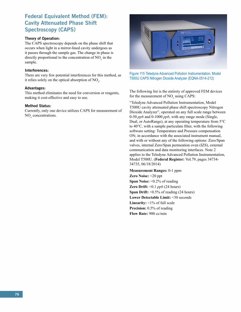
76
Federal Equivalent Method (FEM): Cavity Attenuated Phase Shift Spectroscopy (CAPS)Theory of Operation:The CAPS spectroscopy depends on the phase shift that occurs when light in a mirror-lined cavity undergoes as it passes through the sample gas. The change in phase is directly proportional to the concentration of NOx in the sample.
Interferences:There are very few potential interferences for this method, as it relies solely on the optical absorption of NO2.
Advantages:This method eliminates the need for conversion or reagents, making it cost-effective and easy to use.
Method Status:Currently, only one device utilizes CAPS for measurement of NOx concentrations.
Figure 115 Teledyne Advanced Pollution Instrumentation, Model T500U CAPS Nitrogen Dioxide Analyzer (EQNA-0514-212)
The following list is the entirety of approved FEM devices for the measurement of NOx using CAPS:
“Teledyne Advanced Pollution Instrumentation, Model T500U cavity attenuated phase shift spectroscopy Nitrogen Dioxide Analyzer”, operated on any full scale range between 0-50 ppb and 0-1000 ppb, with any range mode (Single, Dual, or AutoRange), at any operating temperature from 5°C to 40°C, with a sample particulate filter, with the following software setting: Temperature and Pressure compensation ON; in accordance with the associated instrument manual, and with or without any of the following options: Zero/Span valves, internal Zero/Span permeation oven (IZS), external communication and data monitoring interfaces. Note 2 applies to the Teledyne Advanced Pollution Instrumentation, Model T500U. (Federal Register: Vol.79, pages 34734-34735, 06/18/2014)
Measurement Ranges: 0-1 ppmZero Noise: <20 pptSpan Noise: <0.2% of readingZero Drift: <0.1 ppb (24 hours)Span Drift: <0.5% of reading (24 hours)Lower Detectable Limit: <30 secondsLinearity: <1% of full scalePrecision: 0.5% of readingFlow Rate: 900 cc/min

77
8.0 Federal Reference Methods (FRM) and Federal Equivalent Methods (FEMs):Lead (Pb)
Lead (Pb):Criteria Pollutant: Lead (Pb)
Federal Reference Method (FRM): Reference Method for the Determination of Lead (Pb) in Total Suspended Particulate (TSP) Matter {Collected from Ambient Air Using a High-Volume Sampler} (CFR 40, Part 50, Appendix G)Theory of Operation:ICP-MS monitors rely on the method of measurement described in Appendix G of 40 CFR, Part 50: “Ambient air suspended particulate matter is collected on a glass-fiber filter for 24 hours using a high volume air sampler. The analysis of the 24-hour samples may be performed for either individual samples or composites of the samples collected over a calendar month or quarter…. Lead in the particulate matter is solubilized by extraction with nitric acid (HNO3) facilitated by heat or by a mixture of HNO3 and hydrochloric acid (HCl) facilitated by ultrasonication. The lead content of the sample is analyzed by atomic absorption spectrometry using an air-acetylene flame, the 283.3 or 217.0 nm lead absorption line, and the optimum instrumental conditions recommended by the manufacturer.”
Interferences:There are very few potential chemical interferences with this method, however light scattering can lead to measurement errors at the 217.0 nm line. However, this can be corrected by using a dual beam device.
Advantages:This method has essentially no chemical interferences, making it a reliably accurate measurement method.
Method Status:There is currently one approved FRM device for the measurement of lead, the Inductively-Coupled Plasma Mass Spectroscopy (ICP-MS) system:”
Inductively Coupled Plasma Mass Spectroscopy (ICP-MS) (40 CFR Part 50, Appendix G: RFLA-0813-813)
Reference Method for the Determination of Lead in Suspended Particulate Matter Collected from Ambient Air. Federal Register: Vol. 78, page 40000, 7/03/2013
Federal Equivalent Method (FEM): X-Ray Fluorescence SpectrometryTheory of Operation:With X-ray fluorescence spectrometry, X-ray radiation is passed through a sample. This excites atoms in the specimen, causing the particle to emit a fluorescence that is unique to the chemical composition of the specimen. This fluorescence can be measured for intensity, and that intensity is directly proportional to the concentration.
Interferences:Since the resulting fluorescence is unique to lead, interferences can be assumed to be negligible.
Advantages:The method can be used to measure a large range of compounds, if needed. Additionally, the method is safe, being free of the use of any chemicals, and provides fast measurement.
Method Status:The following list is the entirety of approved FRM devices for the measurement of lead using Inductively Coupled Plasma Mass Spectrometry:”
Energy-Dispersive X-Ray Fluorescence Spectrometry (TNRCC) (EQL-0783-058)*“Determination of Lead Concentration in Ambient Particulate Matter by Energy-Dispersive X-Ray Fluorescence Spectrometry (Texas Natural Resource Conservation Commission),” Texas Natural Resource Conservation Commission, P.O. Box 13087, Austin, TX 78711-3087. (Federal Register: Vol. 48, page 29742, 06/28/1983)
Energy-Dispersive X-Ray Fluorescence Spectrometry (NEA, Inc.) (EQL-0589-072)*“Determination of Lead Concentration in Ambient Particulate Matter by Energy-Dispersive X-Ray Fluorescence Spectrometry (NEA, Inc.),” Nuclear Environmental Analysis, Inc., Suite 260, 10950 SW 5th Street, Beaverton, OR 97005. (Federal Register: Vol. 54, page 20193, 05/10/1989)
*Photo Not Available

78
Wavelength Dispersive X-Ray Fluorescence Spectrometry (CA) (EQL-0581-052)*“Determination of Lead Concentration in Ambient Particulate Matter by Wavelength Dispersive X-Ray Fluorescence Spectrometry,” California Department of Health Services, Air & Industrial Hygiene Laboratory, 2151 Berkeley Way, Berkeley, CA 94704. (Federal Register: Vol. 46, page 29986, 06/04/1981)
Federal Reference Method (FRM): Flame/Flameless Atomic Absorption SpectroscopyTheory of Operation:In both flame and flameless atomic absorption spectroscopy, a liquid sample solution is introduced to a flame or furnace, causing molecules to become gaseous atoms. Then, this gaseous sample is analyzed with a source of light, and the concentration can be determined using Beer’s Law.
Interferences:Any particle that is excited by the same wavelength can interfere, however these cases are very limited and unlikely to cause error.
Advantages:Both of these methods are reliable, tested methods for measurement of Lead. They are also largely free of errors and interferences. Additionally, this method is typically the least expensive of any of its counterparts.
Method Status:The following list is the entirety of approved FRM devices for the measurement of lead using Flame/Flameless Atomic Absorption Spectroscopy:”
Flame Atomic Absorption Spectroscopy (FAAS) (EQLA-0813-803)*Equivalent Method for the Determination of Lead in Suspended Particulate Matter Collected from Ambient Air. (Federal Register: Vol. 78, page 40000, 7/03/2013)
Flame Atomic Absorption Spectrometry (EQL-0380-043)*“Determination of Lead Concentration in Ambient Particulate Matter by Flame Atomic Absorption Spectrometry Following Ultrasonic Extraction with Heated HNO3-HCl” (Federal Register: Vol. 45, page 14648, 03/06/1980)
Flameless Atomic Absorption Spectrometry (EPA/RTP, N.C.) (EQL-0380-044)*“Determination of Lead Concentration in Ambient Particulate Matter by Flameless Atomic Absorption Spectrometry (EPA/RTP, NC)” (Federal Register: Vol. 45, page 14648, 03/06/1980)
Flameless (Graphite Furnace) Atomic Absorption (Houston, Texas) (EQL-0895-107)*“Determination of Lead Concentration in Ambient Particulate Matter by Flameless (Graphite Furnace) Atomic Absorption (City of Houston, Texas),” Health and Human Services Department, Environmental Chemistry Service, 1115 S. Braeswood, Houston, TX 77030. (Federal Register: Vol. 60, page 39383, 08/02/1995)
Flameless Atomic Absorption Spectrometry (Omaha) (EQL-0785-059)*“Determination of Lead Concentration in Ambient Particulate Matter by Flameless Atomic Absorption Spectrometry (Omaha-Douglas County Health Department),” Omaha-Douglas County Health Department, 1819 Farnam Street, Omaha, NE 68183. (Federal Register: Vol. 50, page 37909, 09/18/1985)
Federal Reference Method (FRM): Inductively Coupled Plasma-Optical Emission SpectrometryTheory of Operation:In an ICP-OES system, an electrode and a sample generate an electric spark, causing vaporized atoms to be brought to a high-energy plasma state. These atoms create an emission spectrum that is unique to the compound. The intensity of the spectrum created is directly proportional to the concentration of the compound.
Interferences:Due to the high temperature this method operates at, interferences are negligible.
Advantages:ICP-OES devices typically have the least interferences of any other method for measurement of lead. Additionally, this method can typically measure multiple compounds at once, if needed.
Method Status:The following list is the entirety of approved FRM devices for the measurement of Lead using Inductively-Coupled Plasma Optical Emission:”
*Photo Not Available*Photo Not Available

79
Inductively Coupled Argon Plasma-Optical Emission Spectrometry (Doe Run) (EQL-0196-113)*“Determination of Lead Concentration in Ambient Particulate Matter by Inductively Coupled Argon Plasma-Optical Emission Spectrometry (Doe Run Co.),” Doe Run Company, Smelting Division, 881 Main Street Herculaneum, MO 63048. (Federal Register: Vol. 61, page 11404, 03/20/1996)
Inductively Coupled Argon Plasma-Optical Emission Spectrometry (EPA/RTP) (EQL-0380-045)*“Determination of Lead Concentration in Ambient Particulate Matter by Inductively Coupled Argon Plasma-Optical Emission Spectrometry (EPA/RTP, NC)” (Federal Register: Vol. 45, page 14648, 03/06/1980)
Inductively Coupled Argon Plasma-Optical Emission Spectrometry (IL) (EQL-1193-094)*“Determination of Lead Concentration in Ambient Particulate Matter by Inductively Coupled Argon Plasma-Optical Emission Spectrometry (State of Illinois),” State of Illinois, Environmental Protection Agency, Champaign Inorganic Laboratory, 2120 South First Street, Champaign, IL 61820 (Federal Register: Vol. 58, page 61902, 11/23/1993)
Inductively Coupled Argon Plasma-Optical Emission Spectrometry (Kansas) (EQL-0592-085)*“Determination of Lead Concentration in Ambient Particulate Matter by Inductively Coupled Argon Plasma-Optical Emission Spectrometry (State of Kansas),” State of Kansas, Department of Health and Environment, Forbes Field, Building 740, Topeka, KS 66620-0001. (Federal Register: Vol. 57, page 20823, 05/15/1992)
Inductively Coupled Argon Plasma-Optical Emission Spectrometry (Montana) (EQL-0483-057)*“Determination of Lead Concentration in Ambient Particulate Matter by Inductively Coupled Argon Plasma-Optical Emission Spectrometry (State of Montana),” State of Montana, Department of Health and Environmental Sciences, Cogswell Building, Helena, MT 59620. (Federal Register: Vol. 48, page 14748, 04/05/1983)
Inductively Coupled Argon Plasma-Optical Emission Spectrometry (NETI) (EQL-1188-069)*“Determination of Lead Concentration in Ambient Particulate Matter by Inductively Coupled Argon Plasma-Optical Emission Spectrometry (Northern Engineering and Testing, Inc.),” Northern Engineering and Testing, Inc., P.O. Box 30615, Billings, MT 59107. (Federal Register: Vol. 53, page 44947, 11/07/1988)
Inductively Coupled Argon Plasma-Optical Emission Spectrometry (NH) (EQL-1290-080)*“Determination of Lead Concentration in Ambient Particulate Matter by Inductively Coupled Argon Plasma-Optical Emission Spectrometry (State of New Hampshire),” State of New Hampshire, Department of Environmental Services, Laboratory Service Unit, 6 Hazen Drive (P.O. Box 95) Concord, NH 03302-0095. (Federal Register: Vol. 55, page 49119, 11/26/1990)
Inductively Coupled Argon Plasma-Optical Emission Spectrometry (PA) (EQL-0592-086)*“Determination of Lead Concentration in Ambient Particulate Matter by Inductively Coupled Argon Plasma-Optical Emission Spectrometry (Commonwealth of Pennsylvania),” Commonwealth of Pennsylvania, Department of Environmental Resources, P.O. Box 2357, Harrisburg, PA 17105-2357. (Federal Register: Vol. 57, page 20823, 05/15/1992)
Inductively Coupled Argon Plasma-Optical Emission Spectrometry (Pima, AZ) (EQL-0995-109)*“Determination of Lead Concentration in Ambient Particulate Matter by Inductively Coupled Argon Plasma-Optical Emission Spectrometry (Pima County, Arizona),” Pima County, Wastewater Management Department, 201 North Stone Avenue, Tucson, Arizona 85701-1207. (Federal Register: Vol. 60, page 54684, 10/25/1995)
Inductively Coupled Argon Plasma-Optical Emission Spectrometry (RI) (EQL-0888-068)*“Determination of Lead Concentration in Ambient Particulate Matter by Inductively Coupled Argon Plasma-Optical Emission Spectrometry (State of Rhode Island),” State of Rhode Island Department of Health, Air Pollution Laboratory, 50 Orms Street, Providence, RI 02904 (Federal Register: Vol. 53, page 30866, 08/16/1988)
*Photo Not Available*Photo Not Available
80
Inductively Coupled Argon Plasma-Optical Emission Spectrometry (Silver Valley) (EQL-1288-070)*“Determination of Lead Concentration in Ambient Particulate Matter by Inductively Coupled Argon Plasma-Optical Emission Spectrometry (Silver Valley Laboratories),” Silver Valley Laboratories, Inc., P.O. Box 929, Kellogg, ID 83837. (Federal Register: Vol. 53, page 48974, 12/05/1988)
Inductively Coupled Argon Plasma-Optical Emission Spectrometry (WV) (EQL-0694-096)*“Determination of Lead Concentration in Ambient Particulate Matter by Inductively Coupled Argon Plasma-Optical Emission Spectrometry (State of West Virginia),” State of West Virginia, Department of Commerce, Labor and Environmental Resources, Division of Environmental Protection, 1558 Washington Street East, Charleston, WV 25311-2599 (Federal Register: Vol. 59, page 29429, 06/07/1994)
Inductively Coupled Plasma-Atomic Emission Spectroscopy (US EPA/OAQPS) (EQL-0311-196)*“Heated Ultrasonic Nitric and Hydrochloric Acid Digestion and ICP/AES Analysis for Lead (Pb) on TSP High-Volume Filters.” A sample of total suspended particulate matter (TSP) is collected on a glass fiber filter, using the sampler and procedure of the EPA Reference Method for the Determination of Suspended Particulate Matter in the Atmosphere (High-Volume Method) (40 CFR 50, Appendix B). The TSP sample is extracted with a solution of nitric and hydrochloric acid, heated in an ultrasonic bath to 80ºC for one hour, and brought to a final volume of 40 mL. The lead content of the sample extract is analyzed by Inductively Coupled Plasma-Atomic Emission Spectrometry (ICP-AES), based on EPA SW-846 Method 6010C. (Federal Register: Vol. 76, page 15974, 03/22/2011)
Federal Reference Method (FRM): Inductively Coupled Plasma-Mass Spectrometry (ICP-MS)Theory of Operation:Similar to ICP-OES systems, ICP-MS systems rely on the conversion of a liquid sample to an aerosol, which is then injected through a high-energy plasma to separate individual atoms. These atoms are then passed through a mass spectrometer, where concentration can be determined.
Interferences:Any ion having similar mass to the substance of interest will interfere. However, these cases are very limited for lead, so interferences can be assumed to be negligible.
Advantages:ICP devices provide the greatest available accuracy for measurement of lead. ICP devices are free from most interferences and they are a reliable method of measurement.
Method Status:The following list is the entirety of approved FRM devices for the measurement of Lead using Inductively-Coupled Plasma Optical Emission:
Inductively Coupled Argon Plasma-Mass Spectrometry (Pima Co., AZ) (EQL-0995-110)*“Determination of Lead Concentration in Ambient Particulate Matter by Inductively Coupled Plasma-Mass Spectrometry (Pima County, Arizona),” Pima County, Wastewater Management Department, 201 North Stone Avenue, Tucson, Arizona 85701-1207. (Federal Register: Vol. 60, page 54684, 10/25/1995)
Inductively Coupled Plasma - Mass Spectrometry (Inter-Mountain Labs, Inc.) (EQL-0310-189)*“Procedure for Determination of Lead in Ambient TSP by Hot Plate Acid Extraction and ICP-MS Analysis,” where total suspended particulate matter (TSP ) is collected according to 40 CFR Appendix B to part 50, EPA Reference Method for the Determination of Suspended Particulate Matter in the Atmosphere (High-Volume Method), extracted on a hot plate with 3M HNO3 according to 40 CFR Appendix G to part 50, EPA Reference Method for the Determination of Lead in Suspended Particulate Matter Collected from Ambient Air, and analyzed by Inductively Coupled Plasma-Mass Spectrometry (ICP-MS) based on EPA SW-846 Method 6020A. (Federal Register: Vol. 75, page 9894, 03/04/2010)
Inductively Coupled Plasma - Mass Spectrometry (US EPA/OAQPS) (EQL-0510-191)*“Determination of Lead Concentration in TSP by Inductively Coupled Plasma Mass Spectrometry (ICP-MS) with Heated Ultrasonic Nitric and Hydrochloric Acid Filter Extraction,” where total suspended particulate matter (TSP) is collected according to 40 CFR Appendix B to part 50, EPA Reference Method for the Determination of Suspended Particulate Matter in the Atmosphere (High-Volume Method), extracted with a solution of nitric and hydrochloric acids, heated to 80° C and sonicated for one hour, brought to a final volume of 40mL, and analyzed by Inductively Coupled Plasma-Mass Spectrometry (ICP-MS) based on EPA SW-846 Method 6020A. (Federal Register: Vol.75, page 30022, 05/28/2010)
*Photo Not Available*Photo Not Available
81
Inductively Coupled Plasma - Mass Spectrometry (US EPA/Region 9) (EQL-0710-192)*‘‘Heated Nitric Acid Hot Block Digestion and ICP/MS Analysis for Lead (Pb) on TSP High-Volume Filters.” In this method, total suspended particulate matter (TSP) is collected on glass fiber filters according to 40 CFR Appendix B to part 50, EPA Reference Method for the Determination of Suspended Particulate Matter in the Atmosphere (High-Volume Method), extracted with a solution of nitric acid, heated on a hot block to 95°C for one hour, and brought to a final volume of 50 ml. The lead content of the sample extract is analyzed by Inductively Coupled Plasma-Mass Spectrometry (ICP–MS) based on EPA Method 200.8 and SW–846 Method 6020A. (Federal Register: Vol.75, page 45627, 08/03/2010)
Inductively Coupled Plasma- Mass Spectrometry (Eastern Research Group, Inc.) (EQL–0512–201)*“Determination of Lead in TSP by Inductively Coupled Plasma Mass Spectrometry (ICP-MS) with Hot Block Dilute Acid and Hydrogen Peroxide Filter Extraction.” In this method, total suspended particulate matter (TSP) is collected on glass fiber filters according to 40 CFR Appendix G to Part 50, “EPA Reference Method for the Determination of Lead in Suspended Particulate Matter Collected From Ambient Air”. The filter samples are extracted in a hot block at 95°C with a solution of dilute hydrochloric acid and nitric acid and two aliquots of hydrogen peroxide, for a total of two and a half hours extraction time. The samples are brought to a final volume of 50 mL and the lead content of the sample extract is analyzed by Inductively Coupled Plasma-Mass Spectrometry (ICP-MS) based on EPA Compendium Method IO-3.5 and SW-846 Method 6020A. (Federal Register: Vol. 77, page 32632, 06/01/2012)
Inductively Coupled Plasma- Mass Spectrometry (Eastern Research Group, Inc.) (EQL–0512–202)*“Determination of Lead in PM10 by Inductively Coupled Plasma Mass Spectrometry (ICP-MS) with Hot Block Dilute Acid and Hydrogen Peroxide Filter Extraction.” In this method, PM10 particulate matter is collected on Teflon® membrane filters according to 40 CFR Appendix Q to part 50, EPA Reference Method for the Determination of Lead in Particulate Matter as PM10 Collected From Ambient Air. The filter samples are extracted in a hot block at 95°C with a solution of hydrochloric acid, nitric acid, and hydrofluoric acid and an aliquot of hydrogen peroxide for a total of two and a half hours extraction time. Samples are brought to a final volume of 50 mL and analyzed by Inductively Coupled Plasma-Mass Spectrometry (ICP-MS) based on EPA Compendium Method IO-3.5 and SW-846 Method 6020A. Federal Register: Vol. 77, page 32632, 06/01/2012
Inductively Coupled Plasma- Mass Spectrometry (South Coast Air Quality Management District Laboratory) (EQL-0514-213)*“Determination of Lead (PB) on TSP Hi-Volume Filters by Microwave Assisted Digestion and Time of Flight Inductively Coupled Plasma Mass Spectrometry (TOF ICP-MS).” A sample of total suspended particulate matter (TSP) is collected on a glass fiber filter, using the sampler and procedure of the EPA Reference Method for the Determination of Suspended Particulate Matter in the Atmosphere (High-Volume Method) (40 CFR 50, Appendix B). The TSP sample is extracted with a solution of nitric and digested in a microwave digestion system at 175º C for 15 minutes, centrifuged for 30 minutes at 2000 rpm, and brought to a final acid concentration of 2-3%. The lead content of the sample extract is analyzed by Time of Flight Inductively Coupled Plasma Mass Spectrometry (TOF ICP-MS), based on EPA SW-846 Method 6010C. (Federal Register: Vol.79, pages 34734-34735 06/18/2014)
*Photo Not Available*Photo Not Available

83
9.0 References: EPA Reference and Equivalent Methods
1. Code of Federal Regulations, Vol. 40, Part 50 (Explanations for all reference methods)
PM10
2. RAAS FRM PM2.5/PM10 Sampler Series Product Specifications (http://o.b5z.net/i/u/10004484/i/brochures/Particulate Monitoring/Thermo_High_Volume_Sampler_Brochure.pdf)
3. BGI Incorporated PQ100 Brochure (http://bgi.mesalabs.com/wp-content/uploads/sites/35/2014/10/PQ100.04MAY2015.pdf)
4. Ecotech HiVol 3000 High Volume Air Sampler Brochure (http://ecotech.com/wp-content/uploads/2015/02/HiVol-3000.pdf)
5. Thermo Scientific Partisol 2000i Air Sampler Specifications (http://www.thermoscientific.com/en/product/partisol-2000i-air-sampler.html)
6. Thermo Scientific Partisol 2025i Sequential Air Sampler Specifications (http://www.thermoscientific.com/en/product/partisol-2025i-sequential-air-sampler.html)
7. Tisch Environmental TE-Wilbur10 Particulate Sampler Manual (http://tisch-env.com/wp-content/uploads/2015/06/TE-Wilbur-Product-Manual-Complete-REV2.15.pdf)
8. Explanation of Beta Attenuation Principle (http://www.metone.com/docs/bam1020_whitepaper_2008a485awma.pdf) (https://www.horizons.govt.nz/assets/publications/managing-our-environment/air-quality/Beta-Attenuation-Monitor.pdf)
9. DKK-TOA FPM 222/223 PM10 Monitor Specification Sheet (http://static1.1.sqspcdn.com/static/f/1216070/16103926/1326907149060/fpm.pdf?token=AgaE52abzmmTDoHcHlWPO%2BeEhf0%3D)
10. Environnement S.A. MP101M Real Time Particulate Monitor Specifications (http://www.environnement-sa.com/products-page/en/air-quality-monitoring-en/mp101m-with-cpm-option/)
11. Met One BAM-1020 Continuous Particulate Monitor Datasheet (http://www.metone.com/docs/bam1020_datasheet.pdf)
12. OPSIS Model SM200 PM10 Monitor Product Datasheet (http://www.et.co.uk/docs/A17%20SM200%20Product%20Datasheet.pdf)
13. Teledyne API Model 602 BetaPLUS Datasheet (http://www.teledyne-api.com/pdfs/602_Literature_RevB.pdf)
14. Thermo Scientific Model 5014i Beta Continuous Ambient Monitor Specifications (http://www.thermoscientific.com/en/product/5014i-beta-continuous-ambient-particulate-monitor.html)
15. TEOM Principle Explanation (https://www.qld.gov.au/environment/pollution/monitoring/air-pollution/oscillating-microbalance/)
16. Thermo Scientific TEOM 1400 AB Continuous Ambient Particulate Monitor Specifications (http://www.thermoscientific.com/en/product/continuous-ambient-particulate-teom-monitor-series-1400ab.html)
17. Thermo Scientific 1405 DF TEOM Continuous Dichotomous Ambient Particulate Monitor Specifications (http://www.thermoscientific.com/en/product/1405-df-teom-continuous-dichotomous-ambient-air-monitor.html)
18. Thermo Scientific Partisol 2000i-D Dichotomous Air Monitor Specifications (http://www.thermoscientific.com/en/product/partisol-2000i-d-dichotomous-air-sampler.html)
19. Thermo Scientific Partisol 2025i-D Dichotomous Sequential Air Sampler Specifications (http://www.thermoscientific.com/en/product/partisol-2025i-d-dichotomous-sequential-air-sampler.html)
PM2.5
20. RAAS FRM PM2.5/PM10 Sampler Series Product Specifications (http://o.b5z.net/i/u/10004484/i/brochures/Particulate%20Monitoring/Thermo_High_Volume_Sampler_Brochure.pdf)
21. BGI PQ200 Ambient Air Particulate Sampler Brochure (http://bgi.mesalabs.com/wp-content/uploads/sites/35/2014/10/PQ200.20FEB2015.pdf)
22. Tisch Environmental TE-Wilbur2.5 Particulate Sampler Manual (http://tisch-env.com/wp-content/uploads/2015/06/TE-Wilbur-Product-Manual-Complete-REV2.15.pdf)
23. Environnement S.A. MP101M Real Time Particulate Monitor Specifications (http://www.environnement-sa.com/products-page/en/air-quality-monitoring-en/mp101m-with-cpm-option/)
24. Met One BAM-1020 Continuous Particulate Monitor Datasheet (http://www.metone.com/docs/bam1020_datasheet.pdf)
25. Teledyne API Model 602 BetaPLUS Datasheet (http://www.teledyne-api.com/pdfs/602_Literature_RevB.pdf)
84
26. Thermo Scientific Model 5014i Beta Continuous Ambient Monitor Specifications (http://www.thermoscientific.com/en/product/5014i-beta-continuous-ambient-particulate-monitor.html)
27. Thermo Scientific Model 5030i SHARP Monitor Specifications (http://www.thermoscientific.com/en/product/model-5030i-sharp-monitor.html)
28. VSCC Principle Explanation (http://bgi.mesalabs.com/wp-content/uploads/sites/35/2015/02/vsccref6-2.946.pdf)
29. BGI Incorporated Model PQ-200 VSCC Manual (http://bgi.mesalabs.com/wp-content/uploads/sites/35/2015/02/vsccref6-2.946.pdf)
30. OPSIS Model SM200 PM2.5 Monitor Product Datasheet (http://www.et.co.uk/docs/A17%20SM200%20Product%20Datasheet.pdf)
31. Thermo Electron Model RAAS2.5 FEM PM2/5 Air Sampler Series Specifications (http://o.b5z.net/i/u/10004484/i/brochures/Particulate%20Monitoring/Thermo_High_Volume_Sampler_Brochure.pdf)
32. Thermo Scientific Partisol 2000i Air Sampler Specifications (http://www.thermoscientific.com/en/product/partisol-2000i-air-sampler.html)
33. Thermo Scientific Partisol 2025i Sequential Air Sampler Specifications (http://www.thermoscientific.com/en/product/partisol-2025i-sequential-air-sampler.html)
34. Tisch Environmental TE-Wilbur2.5 Particulate Sampler Manual (http://tisch-env.com/wp-content/uploads/2015/06/TE-Wilbur-Product-Manual-Complete-REV2.15.pdf)
35. Thermo Scientific TEOM Model 1400a Ambient Particulate Monitor Specifications (http://www.thermoscientific.com/en/product/continuous-ambient-particulate-teom-monitor-series-1400ab.html)
36. Thermo Scientific 1405 DF TEOM Continuous Dichotomous Ambient Particulate Monitor Specifications (http://www.thermoscientific.com/en/product/1405-df-teom-continuous-dichotomous-ambient-air-monitor.html)
37. Thermo Scientific Partisol 2000i-D Dichotomous Air Monitor Specifications (http://www.thermoscientific.com/en/product/partisol-2000i-d-dichotomous-air-sampler.html)
38. Thermo Scientific Partisol 2025i-D Dichotomous Sequential Air Sampler Specifications (http://www.thermoscientific.com/en/product/partisol-2025i-d-dichotomous-sequential-air-sampler.html)
39. Laser Aerosol Spectroscopy Principle Explanation (http://www.intecconinc.com/pdf/presentation/grimm_inteccon.pdf)
PM2.5-10
40. Grimm Model EDM 180 Monitor Manual (http://www.laftech.com.au/products/dust-monitoring/fixed-dust-monitoring-stations/grimm-edm180#specifications)
41. Thermo Scientific Partisol 2000i PM2.5-10 Air Sampler Specifications (http://www.thermoscientific.com/en/product/partisol-2000i-air-sampler.html)
42. Thermo Scientific Partisol 2025i PM2.5-10 Sequential Air Sampler Specifications (http://www.thermoscientific.com/en/product/partisol-2025i-sequential-air-sampler.html)
43. Teledyne API Model 602 BetaPLUS Datasheet (http://www.teledyne-api.com/pdfs/602_Literature_RevB.pdf)
44. Thermo Scientific 1405 DF TEOM Continuous Dichotomous Ambient Particulate Monitor Specifications (http://www.thermoscientific.com/en/product/1405-df-teom-continuous-dichotomous-ambient-air-monitor.html)
45. Thermo Scientific Partisol 2000i-D Dichotomous Air Monitor Specifications (http://www.thermoscientific.com/en/product/partisol-2000i-d-dichotomous-air-sampler.html)
46. Thermo Scientific Partisol 2025i Sequential Air Sampler Specifications (http://www.thermoscientific.com/en/product/partisol-2025i-sequential-air-sampler.html)
47. Tisch Environmental TE-Wilbur2.5 and TE-Wilbur10 Sampler Pair Manual (http://tisch-env.com/wp-content/uploads/2015/06/TE-Wilbur-Product-Manual-Complete-REV2.15.pdf)
SO2
48. SO2 U.V. Fluorescence Principle Explanation (https://dec.alaska.gov/air/am/SO2_SOP_13feb12.pdf)
49. DKK-TOA Corp. Model GFS-112E U.V. Fluorescent SO2 Analyzer Specifications (http://static1.1.sqspcdn.com/static/f/1216070/16103887/1326907039650/so2_analyser.pdf?token=izt%2BGaFbPm5q9n0NkV4ZGfPT6R0%3D)
50. Ecotech Serinus 50 SO2 Analyzer (http://ecotech.com/wp-content/uploads/2015/01/Serinus-50.pdf)
51. Environnement S.A. AF22M Sulfur Dioxide Analyzer (http://www.environnement-sa.com/products-page/en/air-quality-monitoring-en/af22m-sulfur-dioxide-analyzer-so2/)
52. Horiba Models APSA-360 SO2 Monitors Technical Report (http://www.horiba.com/uploads/media/RE01-06-029.pdf)
53. Horiba Model APSA-370 SO2 Monitors Specifications (http://www.horiba.com/process-environmental/products/ambient/details/apsa-370-ambient-sulfur-dioxide-monitor-272/)
85
54. SERES Model SF 2000 G SO2 Analyzer Brochure (http://www.seres-france.com/wp-content/uploads/2014/07/Sf2000g_Brochure_UK_120327.pdf)
55. Teledyne API Model T100 U.V. Fluorescent SO2 Analyzer Specifications (http://www.teledyne-api.com/pdfs/T100_Literature_RevC.pdf)
56. Ecotech Model EC9850 Series SO2 Analyzer User Manual (http://ecotech.com/wp-content/uploads/2015/03/EC9850-Operation-Manual.pdf)
57. Thermo Electron Model 43 SO2 Analyzer Specifications (http://www.thermoscientific.com/en/product/model-43-i-i-i-so-sub-2-sub-analyzer.html)
58. Thermo Electron Model 43i SO2 Analyzer Specifications (http://www.thermoscientific.com/en/product/model-43-i-i-i-so-sub-2-sub-analyzer.html)
O3
59. O3 U.V. Photometry Principle Explanation (http://mattson.creighton.edu/Ozone/OzoneEPAMethod.pdf)
60. 2B Technologies Model 202 Ozone Monitor Specifications (http://www.twobtech.com/model_202.htm)
61. 2B Technologies Model 211 Ozone Monitor Specifications (http://www.twobtech.com/model_211.htm)
62. 2B Technologies Model 106-L Ozone Monitor Specifications (http://www.twobtech.com/model_106.htm)
63. Dasibi Models 1008-AH Ozone Analyzer Manual (http://www.scribd.com/doc/7238918/DasibiOzoneMonitorManual-1008#scribd)
64. DKK-TOA Model GUX-313E Ambient O3 Analyzer Specification Sheet (http://static1.1.sqspcdn.com/static/f/1216070/16103858/1326906928990/o3_analyser.pdf?token=T%2BONY6Nucv7ydjZevEomG3jhY8E%3D)
65. Ecotech Serinus 10 Ozone Analyzer Specification Sheets (http://ecotech.com/wp-content/uploads/2015/01/Serinus-101.pdf)
66. Environnement O342M Ozone Analyzer Specifications (http://www.environnement-sa.com/products-page/en/air-quality-monitoring-en/o342m-ozone-analyzer/)
67. Environnement S.A. Model O3 42e UV Ozone Analyzer Specifications (http://www.environnement-sa.com/products-page/en/air-quality-monitoring-en/o342m-ozone-analyzer/)
68. Horiba Instruments Model APOA-360 Ozone Monitor Manual (http://www.horiba.com/uploads/media/RE01-06-029.pdf)
69. Horiba Instruments Model APOA-370 Ozone Monitor Specifications (http://www.horiba.com/us/en/process-environmental/products/ambient/details/apoa-370-ambient-ozone-monitor-276/)
70. SERES OZ 2000G Ozone Analyzer Specifications (http://www.seres-france.com/product-list/oz-2000g-2/)
71. SIR SA Model S-5014 UV Absorption O3 Analyzer Manual (http://www.jusun.com.tw/en-S-5014%20OZONE%20ANALYZER.pdf)
72. Sutron Corporation Model 6030 O3 Analyzer Specifications (http://www.sutron.com/aq/documents/2030-ozone-transfer-standard-model-datasheet.pdf)
73. Teledyne API Model T400 Ozone Analyzer Specification Sheet (http://www.teledyne-api.com/pdfs/T400_Literature.pdf)
74. Teledyne API Model T204 Analyzer Specification Sheet (http://www.teledyne-api.com/products/T204.asp)
75. Ecotech Model EC 9810 Ozone Analyzer Manual (http://ecotech.com/wp-content/uploads/2015/03/EC9810-Operation-Manual.pdf)
76. Thermo Electron Models 49i Specifications (http://www.thermoscientific.com/en/product/model-49-i-i-i-ozone-analyzer.html)
77. Environnement S.A. SANOA Multigas Longpath Monitoring System (http://www.environnement-sa.com/products-page/en/air-quality-monitoring-en/sanoa-2/)
78. Opsis Model System 300 Open Path Ambient Air Monitoring Systems Specifications Brochure (http://ecotech.com/wp-content/uploads/2015/03/Opsis-BRO-B03_System300_Eng.pdf)
CO79. Dasibi Model 3008 CO Analyzer Manual (http://www.
scribd.com/doc/7238904/DasibiCO3008MonitorManual#scribd)
80. DKK-TOA Model GFC-311E Ambient CO Analyzer Specification Sheet (http://static1.1.sqspcdn.com/static/f/1216070/16103959/1326907230750/co_analyser.pdf?token=QnwaF0tRdEh%2FFPUjMBeq%2BHB%2FDeA%3D)
81. Ecotech Serinus 30 CO Analyzer Specifications (http://ecotech.com/wp-content/uploads/2015/01/Serinus-30.pdf)
82. Environnement SA CO12M CO Monitor Specifications (http://www.environnement-sa.com/products-page/en/air-quality-monitoring-en/co12m-carbon-monoxide-analyzer/)
83. Horiba APMA-360 CO Monitor Manual (http://www.horiba.com/uploads/media/RE01-06-029.pdf)
84. Horiba APMA-370 CO Monitor Specifications (http://www.horiba.com/process-environmental/products/ambient/details/apma-370-ambient-carbon-monoxide-monitor-270/)
85. SIR SA Model S-5006 CO Analyzer Manual (http://www.euritmicgrup.ro/UserFiles/File/PDF-uri%20produse/241_en_SIR%20-%20CO%20Analizer.pdf)

86
86. Teledyne API T300 CO Analyzer Manual (http://www.teledyne-api.com/pdfs/T300_Literature_RevC.pdf)
87. Ecotech Model EC9830 CO Analyzer Manual (http://ecotech.com/wp-content/uploads/2015/01/EC9830-Operation-Manual.pdf)
88. Thermo Electron 48i CO Analyzer Specifications (http://www.thermoscientific.com/en/product/model-48-i-i-i-co-analyzer.html)
NOx
89. DKK-TOA Model GLN-314E NOx Analyzer Specification Sheet (http://static1.1.sqspcdn.com/static/f/1216070/16103835/1326906830950/nox_analyser.pdf?token=u%2Foe1qOx6FRFmimilFRMpAcEwR8%3D)
90. Ecotech Serinus 40 NOx Analyzer Specifications (http://ecotech.com/wp-content/uploads/2015/01/Serinus-40.pdf)
91. Environnement S.A. Model AC32M NOx Analyzer Specifications (http://www.environnement-sa.com/products-page/en/air-quality-monitoring-en/ac32m-analyzer-oxides-nitrogen-no-nox-no2-2/)
92. Horiba APNA-360 NOx Analyzer Manual (http://www.horiba.com/uploads/media/RE01-06-029.pdf)
93. Horiba APNA-370 NOx Monitor Specifications (http://www.horiba.com/us/en/process-environmental/products/ambient/details/apna-370-ambient-nox-monitor-274/)
94. Teledyne API Model T200 NOx Analyzer Specifications (http://www.teledyne-api.com/products/T200.asp)
95. Ecotech EC9841T NOx Monitor Brochure (http://ecotech.com/wp-content/uploads/2015/03/EC9841T-NO_NO2_NOX-Trace-Analyser-Brochure.pdf)
96. Thermo Environmental Model 42i NOx Monitor Specifications (http://www.thermoscientific.com/en/product/model-42-em-i-em-no-no-sub-2-sub-no-sub-x-sub-analyzer.html)
97. Sodium Arsenite Method for NOx Principle Explanation (http://www.tandfonline.com/doi/pdf/10.1080/00022470.1977.10470455)
98. TGS-ANSA Method Principle Explanation (http://nepis.epa.gov/Exe/ZyNET.exe/9101EPX1.TXT?ZyActionD=ZyDocument&Client=EPA&Index=Prior+to+1976&Docs=&Query=&Time=&EndTime=&SearchMethod=1&TocRestrict=n&Toc=&TocEntry=&QField=&QFieldYear=&QFieldMonth=&QFieldDay=&IntQFieldOp=0&ExtQFieldOp=0&XmlQuery=&File=D%3A%5Czyfiles%5CIndex%20Data%5C70thru75%5CTxt%5C00000021%5C9101EPX1.txt&User=ANONYMOUS&Password=anonymous&SortMethod=h%7C-&MaximumDocuments=1&FuzzyDegree=0&ImageQuality=r75g8/r75g8/x150y150g16/i425&Display=p%7Cf&DefSeekPage=x&SearchBack=ZyActionL&Back=ZyActionS&BackDesc=Results%20page&MaximumPages=1&ZyEntry=1&SeekPage=x&ZyPURL)
99. Environnement S.A. SANOA Multigas Longpath Monitoring System (http://www.environnement-sa.com/products-page/en/air-quality-monitoring-en/sanoa-2/)
100. Opsis Model System 300 Open Path Ambient Air Monitoring Systems Specifications Brochure (http://ecotech.com/wp-content/uploads/2015/03/Opsis-BRO-B03_System300_Eng.pdf)
101. U.V. Photolytic Conversion Principle Explanation (http://www.teledyne-api.com/products/T200UP.asp)
102. Teledyne API Model T200UP Specification Sheet (http://www.teledyne-api.com/pdfs/T200UP_Literature_RevB.pdf)
103. Cavity Attenuated Phase Shift Spectroscopy Method Principle Explanation (http://www.teledyne-api.com/pdfs/T500U_Brochure.pdf)
104. Teledyne API Model T500UP CAPS NOx Monitor Brochure (http://www.teledyne-api.com/pdfs/T500U_Brochure.pdf)
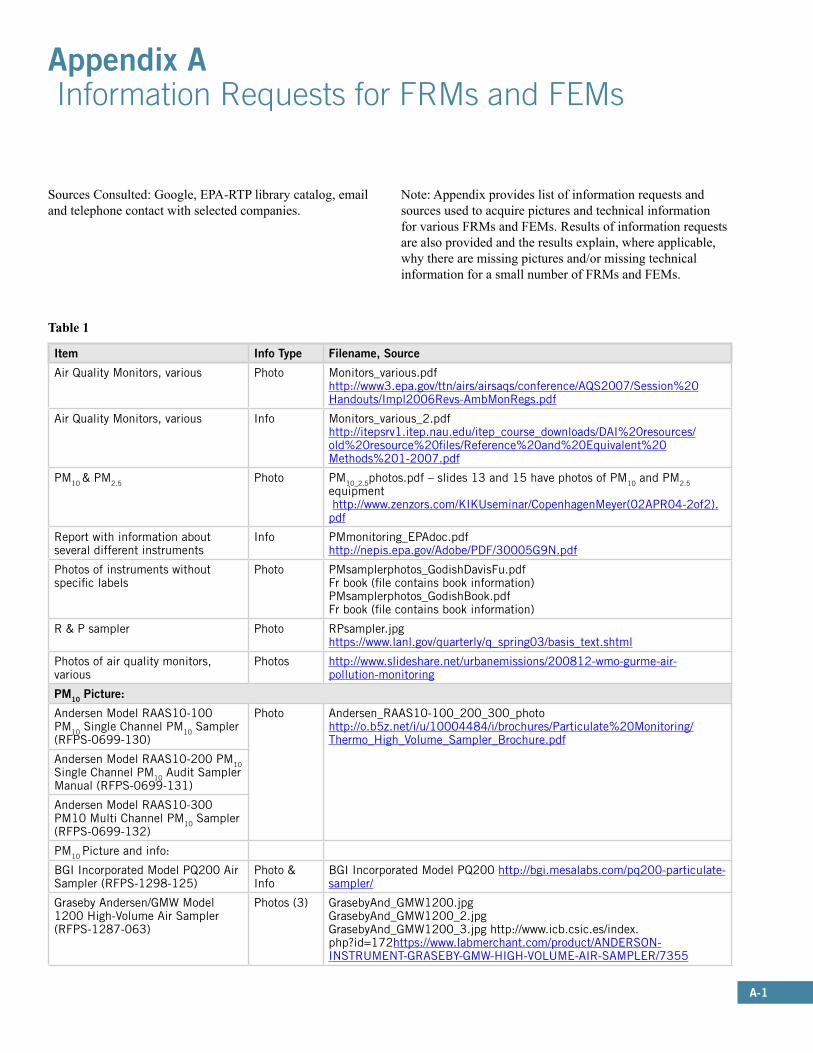
A-1
Appendix A Information Requests for FRMs and FEMs
Item Info Type Filename, Source
Air Quality Monitors, various Photo Monitors_various.pdfhttp://www3.epa.gov/ttn/airs/airsaqs/conference/AQS2007/Session%20Handouts/Impl2006Revs-AmbMonRegs.pdf
Air Quality Monitors, various Info Monitors_various_2.pdfhttp://itepsrv1.itep.nau.edu/itep_course_downloads/DAI%20resources/old%20resource%20files/Reference%20and%20Equivalent%20Methods%201-2007.pdf
PM10 & PM2.5 Photo PM10_2.5photos.pdf – slides 13 and 15 have photos of PM10 and PM2.5 equipment http://www.zenzors.com/KIKUseminar/CopenhagenMeyer(02APR04-2of2).pdf
Report with information about several different instruments
Info PMmonitoring_EPAdoc.pdfhttp://nepis.epa.gov/Adobe/PDF/30005G9N.pdf
Photos of instruments without specific labels
Photo PMsamplerphotos_GodishDavisFu.pdfFr book (file contains book information)PMsamplerphotos_GodishBook.pdfFr book (file contains book information)
R & P sampler Photo RPsampler.jpghttps://www.lanl.gov/quarterly/q_spring03/basis_text.shtml
Photos of air quality monitors, various
Photos http://www.slideshare.net/urbanemissions/200812-wmo-gurme-air-pollution-monitoring
PM10 Picture:
Andersen Model RAAS10-100 PM10 Single Channel PM10 Sampler (RFPS-0699-130)
Photo Andersen_RAAS10-100_200_300_photohttp://o.b5z.net/i/u/10004484/i/brochures/Particulate%20Monitoring/Thermo_High_Volume_Sampler_Brochure.pdf
Andersen Model RAAS10-200 PM10 Single Channel PM10 Audit Sampler Manual (RFPS-0699-131)
Andersen Model RAAS10-300 PM10 Multi Channel PM10 Sampler (RFPS-0699-132)
PM10 Picture and info:
BGI Incorporated Model PQ200 Air Sampler (RFPS-1298-125)
Photo & Info
BGI Incorporated Model PQ200 http://bgi.mesalabs.com/pq200-particulate-sampler/
Graseby Andersen/GMW Model 1200 High-Volume Air Sampler (RFPS-1287-063)
Photos (3) GrasebyAnd_GMW1200.jpgGrasebyAnd_GMW1200_2.jpgGrasebyAnd_GMW1200_3.jpg http://www.icb.csic.es/index.php?id=172https://www.labmerchant.com/product/ANDERSON-INSTRUMENT-GRASEBY-GMW-HIGH-VOLUME-AIR-SAMPLER/7355
Sources Consulted: Google, EPA-RTP library catalog, email and telephone contact with selected companies.
Note: Appendix provides list of information requests and sources used to acquire pictures and technical information for various FRMs and FEMs. Results of information requests are also provided and the results explain, where applicable, why there are missing pictures and/or missing technical information for a small number of FRMs and FEMs.
Table 1

A-2
PM10 Picture (continued)
Graseby Andersen/GMW Model 321-B High-Volume Air Sampler (RFPS-1287-064)
Info Graseby 321-B_321-Cinfo.pdf
Graseby Andersen/GMW Model 321-C High-Volume Air Sampler (RFPS-1287-065)
Graseby Andersen/GMW Models SA241 and SA241M Dichotomous Sampler (RFPS-0789-073)
Emailed company for information, no information provided
Graseby Andersen: photo, model not specified
Photo (model not specified)
GrasebyAndersenTSP.jpghttp://websites.labx.com/osi/detail.cfm?autonumber=51739
Graseby Andersen: PUF sampler Photo GrasebyAndersenPUF.jpghttp://websites.labx.com/osi/detail.cfm?autonumber=51742
Thermo Scientific or Rupprecht & Patashnick Partisol® Model 2000 Air Sampler (RFPS-0694-098)
Info & Photo
RP2000Partisol_Specifications.pdfhttp://o.b5z.net/i/u/10004484/i/brochures/Particulate%20Monitoring/Partisol_Manual_Specifications.pdfRP2000Partisol_quickstart_Photo.pdfhttp://www.atmospheric-research.com/WebSOPs/FRM%20(2025)%20Manuals/FRM%20Operating%20Manual.pdfFrom Thermo Electron Brand:ThermoElectronPartisol.pdfhttp://www.thermo.com.cn/Resources/200802/productPDF_27107.pdf
Tisch Environmental Model TE-6070 PM10 High-Volume Air Sampler or New Star Environmental Model NS-6070 PM10 High-Volume Air Sampler (RFPS-0202-141)
Photo & Info
TischEnvironmental.pdfhttps://tisch-env.com/high-volume-air-sampler/pm10TischTE6070-PM10Specs.pdfhttp://eco-rentalsolutions.com/pm-10-high-volume-air-sampler
Wedding & Associates’ or Thermo Environmental Instruments Inc. Model 600 PM10 High-Volume Sampler (RFPS-1087-062)Thermo Environmental Instruments is now Thermo Fisher Scientific, the air quality monitor division of Thermo Fisher Scientific is called ThermoScientific
Emailed company for info, no information obtained
Graseby Andersen/GMW Model FH621-N Beta Monitor (EQPM-0990-076)
Information http://dd.eionet.europa.eu/vocabularyconcept/aq/measurementequipment/andersenFH621N/view
Wedding & Associates’ or Thermo Environmental Instruments Inc. Model 650 PM10 Beta Gauge (EQPM-0391-081)
Emailed company for info, no information obtained
PM2.5 Picture only:
Andersen Model RAAS2.5-200 PM2.5 Ambient Audit Air Sampler (RFPS-0299-128)
Photo AndersenRAAS2.5calibration.pdf http://bgi.mesalabs.com/wp-content/uploads/sites/35/2014/12/andersen.pdf
Graseby Andersen Model RAAS2.5-100 PM2.5 Ambient Air Sampler (RFPS-0598-119)
Emailed company for info, no information provided
Thermo Electron Model RAAS2.5-200 FEM PM2.5 Audit Air Sampler (RFPS-0299-128 or EQPM-0804-154)
Emailed company for info, no information provided
Thermo Electron Model RAAS2.5-300 FEM PM2.5 Sequential Ambient Air Sampler (RFPS-0598-120 or EQPM-0804-155)
RAAS2.5300.pdfhttps://etd.ohiolink.edu/!etd.send_file?accession=ohiou1187123906&disposition=inline

A-3
Picture and info:
Graseby Andersen Model RAAS2.5-300 PM2.5 Sequential Ambient Air Sampler (RFPS-0598-120)
Information AndersenRAAS2.5-300.pdf http://arb.ca.gov/aaqm/qa/pqao/repository/district_sops/south_coast/pm/south_coast_anderson_pm2point5_sampler_sop.pdf
Met One e-FRM– PM2.5 (RFPS-0315-221)
Photo MetOne_e-RFM.jpghttp://themetoneinstrumentsmonitor.blogspot.com/2015/03/new-product-release-efrm.htmlEmailed MetOne for specifications, no information obtained
Rupprecht & Patashnick Partisol®-FRM Model 2000 PM2.5 Air Sampler (RFPS-0498-117)
Photo & info
RP FRM2.5photo.jpghttp://www.techstuff.com/rpco.htmRP Partisol -FRM2000 PM2.5manual.pdfhttp://itepsrv1.itep.nau.edu/itep_course_downloads/Glenns_FTP%20folder/Michael/2000FRM.pdf
Rupprecht & Patashnick Partisol® Model 2000 PM2.5 Audit Sampler (RFPS-0499-129)
Emailed company for info, no information obtained
Rupprecht & Patashnick Partisol®-Plus Model 2025 Sequential Air Sampler (RFPS-0498-118)
Photo & Info
RP PartisolPlus2025.jpg fromhttp://www.ebay.com/itm/RUPPRECHT-PATASHNICK-PARTISOL-PLUS-2025-AIR-SAMPLER-/331447964059RP PartisolPlus2025_2.jpghttp://www.ebay.com/itm/Rupprecht-Patashnick-Thermo-Scientific-Partisol-Plus-Model-2025-SEE-VIDEO-/252090402301?hash=item3ab1c245fdRP2025PartisolPlus_Manual.pdfFrom http://www.atmospheric-research.com/WebSOPs/FRM%20(2025)%20Manuals/FRM%20Operating%20Manual.pdfRP 2025Manual.pdfhttp://daq.state.nc.us/monitor/QAPlans/pm25/pm25_OPERATOR.pdf
Thermo Environmental Instruments, Incorporated Model 605 “CAPS” Sampler (RFPS-1098-123)
Emailed company for info, no information provided
URG-MASS100 Single PM2.5 FRM Sampler (RFPS-0400-135)
No information found
URG-MASS300 Sequential PM2.5 FRM Sampler (RFPS-0400-136)
No information found
Met One BAM-1022 Real Time Beta Attenuation Mass Monitor-Outdoor PM2.5 FEM Configuration (EQPM-1013-209)
Photo & Info
MetOneBAM1022.jpg (photo) From website below that has a little information.http://s15.a2zinc.net/clients/Corcoran/AGU2014/Public/eBooth.aspx?BoothID=113293Slide presentation with photos and info at this website: http://slideplayer.com/slide/4666485/File download requires social media promotion of product
Rupprecht & Patashnick Partisol® Model 2000 PM2.5 FEM Audit Sampler (RFPS-0499-129 or EQPM-0202-144)
Emailed company for info, no information obtained
Thermo Electron Model RAAS2.5-100 FEM PM2.5 Ambient Air Sampler (RFPS-0598-119 or EQPM-0804-153)
Information ThermoElectronRAAS2.5-100.pdf (specifications on p. 72)https://www.massport.com/media/3108/Final_Quality_Assurance_ProjPlanActMonitoring.pdf

A-4
PM 2.5-10 Picture and info:
BGI Incorporated Model PQ200 Sampler Pair (RFPS-1208-173)
Photo & Info
bgipq200.png http://bgi.mesalabs.com/pq200-particulate-sampler/Website contains links to specifications and other information
Tisch Environmental Model TE-Wilbur Low-Volume Air Particulate Sampler Pair (RFPS-1014-220)
Photo & Info
TE-Wilbur Spec Sheet.pdfhttps://tisch-env.com/low-volume-air-sampler/TE-Wilbur-manual.pdfhttps://tisch-env.com/wp-content/uploads/2015/06/TE-Wilbur-Product-Manual-Complete-REV2.15.pdfTE-wilburphoto.pnghttps://tisch-env.com/resources/product-manualsThe following link has a photo and various specification documents: https://tisch-env.com/low-volume-air-sampler/
Met One Instruments BAM-1020 PM10-2.5 Measurement System (EQPM-0709-185)
Photo & Info
MetOnebam1020_datasheet.pdf From http://www.metone.com/docs/bam1020_datasheet.pdf
Information about multiple monitors for gases or monitors that are not clearly identified
Air Analyzers, Beckman Photo http://pubs.acs.org/doi/pdf/10.1021/es60153a903
Air Analyzers, Dasibi Info Dasibi_multiple gases.pdf(p. 7 contains a little info about several products) https://www.lcghd.org/documents/2012AirPollutionAnnualReport.pdfDasibi_ozone_CO.pdfP. 79- some description of CO 3003 p. 148 some description of 1003-AHfile:///F:/User/UNC/ADVANCED%20REFERENCE/Searches/Hall,%20Eric%20S/airmonitoring/Dasibi_ozone_CO.pdf
Air Analyzers, various Limited info Appendix B contains info on several analyzers - Monitors_various_3.pdfhttp://arb.ca.gov/research/apr/past/arb-5-1032_2app.pdf
Air Analyzers, various Information Monitors_various_4.pdfhttp://nepis.epa.gov/Exe/ZyPDF.cgi/20015SNN.PDF?Dockey=20015SNN.PDF
Environment, S.A., various Limited info Environnement_S.A.pdfStarting on p. A5http://uk-air.defra.gov.uk/assets/documents/reports/empire/lsoman/Appendix_A_Environnement_1M_Series.pdf
SO2
Sulfur dioxide monitor, no information on brand or model
SulfDiox_1978photo.pdfhttp://nepis.epa.gov/Exe/ZyPDF.cgi?Dockey=91017WAK.PDF
Picture and info:
Advanced Pollution Instrumentation, Inc. Model 100 SO2 Analyzer (EQSA-0990-077)
Photo and information
Called Teledyne Advanced Pollution Instrumentation (bought by Teledyne in 2001) - they sent the following manual for model 100A –API_M100A Manual_02164.pdf
Beckman Model 953 Fluorescent Ambient SO2 Analyzer (EQSA-0678-029)
Information http://www.google.com/patents/US4272248
Dasibi Model 4108 U.V. Fluorescence SO2 Analyzer (EQSA-1086-061)
Photo Dasibi 1003H.png http://www.ebay.com/itm/4108-UV-Flourescence-SO2-Analyzer-Dasibi-Environmental-Corp-/231593579869Dasibi4108_v2.pdf http://www.bonanza.com/listings/4108-UV-Flourescence-SO2-Analyzer-Dasibi-Environmental-Corp/277277919
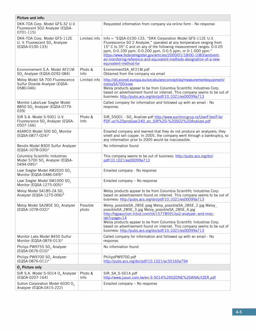
A-5
Picture and info:
DKK-TOA Corp. Model GFS-32 U.V. Fluorescent SO2 Analyzer (EQSA-0701-115)
Requested information from company via online form - No response
DKK-TOA Corp. Model GFS-112E U. V. Fluorescent SO2 Analyzer (EQSA-0100-133)
Limited info Info = “EQSA-0100-133, “DKK Corporation Model GFS-112E U.V. Fluorescence SO 2 Analyzer,” operated at any temperature ranging from 15° C to 35° C and on any of the following measurement ranges: 0-0.05 ppm, 0-0.100 ppm, 0-0.200 ppm, 0-0.5 ppm, or 0-1.000 ppm.”https://www.federalregister.gov/articles/2000/01/18/00-1083/ambient-air-monitoring-reference-and-equivalent-methods-designation-of-a-new-equivalent-method-for
Environnement S.A. Model AF21M SO2 Analyzer (EQSA-0292-084)
Photo & Info
EnvironmentSA_AF21M.pdfObtained from the company via email
Meloy Model SA 700 Fluorescence Sulfur Dioxide Analyzer (EQSA-0580-046)
Limited info http://dd.eionet.europa.eu/vocabularyconcept/aq/measurementequipment/meloySA700/viewMeloy products appear to be from Columbia Scientific Industries Corp. based on advertisement found on internet. This company seems to be out of business: http://pubs.acs.org/doi/pdf/10.1021/es00099a713
Monitor Labs/Lear Siegler Model 8850 SO2 Analyzer (EQSA-0779-039)
Called company for information and followed up with an email - No response.
SIR S.A. Model S-5001 U.V. Fluorescence SO2 Analyzer (EQSA-0507-166)
Photo & Info
SIR_S5001 - SO2 Analizer.pdf http://www.euritmicgrup.ro/UserFiles/File/PDF-uri%20produse/240_en_SIR%20-%20SO2%20Analizer.pdf
ASARCO Model 500 SO2 Monitor (EQSA-0877-024)*
Emailed company and learned that they do not produce air analyzers; they smelt and sell copper. In 2005, the company went through a bankruptcy, so any information prior to 2005 would be inaccessible.
Bendix Model 8303 Sulfur Analyzer (EQSA-1078-030)*
No information found
Columbia Scientific Industries Model 5700 SO2 Analyzer (EQSA-0494-095)*
This company seems to be out of business: http://pubs.acs.org/doi/pdf/10.1021/es00099a713
Lear Siegler Model AM2020 SO2 Monitor (EQSA-0486-049)*
Emailed company - No response
Lear Siegler Model SM1000 SO2 Monitor (EQSA-1275-005)*
Emailed company – No response
Meloy Model SA185-2A SO2 Analyzer (EQSA-1275-006)*
Meloy products appear to be from Columbia Scientific Industries Corp. based on advertisement found on internet. This company seems to be out of business: http://pubs.acs.org/doi/pdf/10.1021/es00099a713
Meloy Model SA285E SO2 Analyzer (EQSA-1078-032)*
Possible photo
Meloy_possibleSA_285E.jpeg Meloy_possibleSA_285E_2.jpg Meloy_possibleSA_285E_3.jpg Meloy_possibleSA_285E_4.jpghttp://hgpauction.hibid.com/lot/15778591/so2-analyzer--and-misc-lab?cpage=14Meloy products appear to be from Columbia Scientific Industries Corp. based on advertisement found on internet. This company seems to be out of business: http://pubs.acs.org/doi/pdf/10.1021/es00099a713
Monitor Labs Model 8450 Sulfur Monitor (EQSA-0876-013)*
Called company for information and followed up with an email - No response.
Philips PW9755 SO2 Analyzer (EQSA-0676-010)*
No information found
Philips PW9700 SO2 Analyzer (EQSA-0876-011)*
PhilipsPW9700.pdfhttp://pubs.acs.org/doi/pdf/10.1021/ac50160a794
O3 Picture only
SIR S.A. Model S-5014 O3 Analyzer (EQOA-0207-164)
Photo & Info
SIR_SA_S-5014.pdfhttp://www.jusun.com.tw/en-S-5014%20OZONE%20ANALYZER.pdf
Sutron Corporation Model 6030 O3 Analyzer (EQOA-0415-222)
Emailed company – No response

A-6
Picture and info:
Beckman Model 950A Ozone Analyzer (RFOA-0577-020)
No information found
Bendix or Combustion Engineering Model 8002 Ozone Analyzer (RFOA-0176-007)
Limited info Slide 5 in Bendix8002_ozone.pdfhttp://www.twobtech.com/linked_files/EPA_FRM_Presentation_Jan_14_2015.pdf“. The ozone level is carefully monitored and an ozone analyzer 30 (such as the Bendix Model 8002). The Bendix Model 8002 ozone analyzer 30 uses a photometrix method detecting the chemiluminescence reaction of ozone and ethylene which is supplied from a tank 32.”https://www.google.com/patents/US4262541https://archive.org/stream/airmonitoringins1979robb/airmonitoringins1979robb_djvu.txt
Columbia Scientific Industries Model 2000 Ozone Meter (RFOA-0279-036)
This company seems to be out of business: http://pubs.acs.org/doi/pdf/10.1021/es00099a713
McMillan (MEC) Models 1100-1, 1100-2, and 1100-3 Ozone Meters: “MEC Model 1100-1 Ozone Meter,” (RFOA-1076-014), “MEC Model 1100-2 Ozone Meter,” (RFOA-1076-015), “MEC Model 1100-3 Ozone Meter,’ (RFOA-1076-016)
McMillan is a subsidiary of Columbia Scientific Industries, which is out of businessO3_McMillan.pdfVery limited information on p. 32http://www.esrl.noaa.gov/gmd/publications/summary_reports/summary_report_4.pdf
Meloy Model OA325-2R Ozone Analyzer (RFOA-1075-003)
Meloy products appear to be from Columbia Scientific Industries Corp. based on advertisement found on internet. This company seems to be out of business: http://pubs.acs.org/doi/pdf/10.1021/es00099a713
Meloy Model OA350-2R Ozone Analyzer (RFOA-1075-004)
Meloy products appear to be from Columbia Scientific Industries Corp. based on advertisement found on internet. This company seems to be out of business: http://pubs.acs.org/doi/pdf/10.1021/es00099a713
Monitor Labs Model 8410E Ozone Analyzer (RFOA-1176-017)
Called company for information and followed up with an email - No response.
Dasibi Models 1003-AH, 1003-PC, or 1003-RS Ozone Analyzers (EQOA-0577-019)
Photo & information
Ozone_Dasibi_GodishBook.pdf (from book, file includes book information)Dasibi 1003H.pnghttp://www.ebay.com/itm/Ozone-analyzer-1003-PC-Dasibi-Environmental-Corp-/231593573485Dasibi1003-AH.jpgDasibi1003-AH_pic2.jpg Dasibi1003-AH_pic3.jpg Dasibi1003-AH_pic4.jpg Dasibi1003-AH_pic5.jpghttp://www.ebay.com/itm/Ozone-analyzer-1003-AH-Dasibi-Environmental-Corp-/261913038702?hash=item3cfb3bcf6eDasibi1003AH_SOP.pdfhttp://www.arb.ca.gov/airwebmanual/aqsbdocs1/v2apxa.pdf
DKK-TOA Corp. Model GUX-113E Ozone Analyzer (EQOA-0200-134)
Requested information from company via online form - No response
Environics Series 300 Ozone Analyzer (EQOA-0990-078)
Photo & Info
EnvironicsS300specs.pdfEnvironicsS300specs_photo.pdfBoth documents obtained from company via email
Environnement S.A. Model O341M UV Ozone Analyzer (EQOA-0895-105)
Photo & Info
EnvironmentSA_O341M.pdfObtained from email correspondence with the company
Monitor Labs/Lear Siegler Model 8810 Ozone Analyzer (EQOA-0881-053)
Called company for information and followed up with an email - No response.
PCI Ozone Corporation Model LC-12 Ozone Analyzer (EQOA-0382-055)
No information found
Philips PW9771 03 Analyzer (EQOA-0777-023)
No information found
Tanabyte Models 722, 723, 724, 725, or 726 Ambient Ozone Analyzer (EQOA-0407-165)
Photo & Info
Model 722 http://www.jiranatee.com/15108404/model-722 http://www.aerosol.com.tw/product_cg50260.htmlModel 723 http://www.tanabyte.com/T723%20Module.htmlModel 724 http://www.tanabyte.com/T724%20Module.htmlModel 725 http://www.tanabyte.com/T725%20Module.htmlModel 726 http://www.tanabyte.com/T726%20Module.html
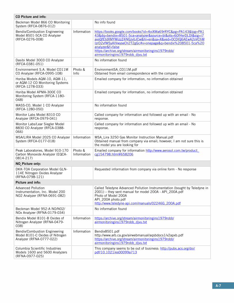
A-7
CO Picture and info:
Beckman Model 866 CO Monitoring System (RFCA-0876-012)
No info found
Bendix/Combustion Engineering Model 8501-5CA CO Analyzer (RFCA-0276-008)
Information https://books.google.com/books?id=4oiXMa69rRYC&pg=PA143&lpg=PA143&dq=bendix+8501-5ca+analyzer&source=bl&ots=60fHxrDLDl&sig=i7avsQfEtdXMYMizzZ4NGzvbJCw&hl=en&sa=X&ved=0CDIQ6AEwA2oVChMIzrD2vfWSyAIVwyseCh2T2gGc#v=onepage&q=bendix%208501-5ca%20analyzer&f=falsehttps://archive.org/stream/airmonitoringins1979robb/airmonitoringins1979robb_djvu.txt
Dasibi Model 3003 CO Analyzer (RFCA-0381-051)
No information found
Environnement S.A. Model CO11M CO Analyzer (RFCA-0995-108)
Photo & Info
EnvironmentSA_CO11M.pdfObtained from email correspondence with the company
Horiba Models AQM-10, AQM-11, or AQM-12 CO Monitoring Systems (RFCA-1278-033)
Emailed company for information, no information obtained
Horiba Model APMA-300E CO Monitoring System (RFCA-1180-048)
Emailed company for information, no information obtained
MASS-CO, Model 1 CO Analyzer (RFCA-1280-050)
No information found
Monitor Labs Model 8310 CO Analyzer (RFCA-0979-041)
Called company for information and followed up with an email - No response.
Monitor Labs/Lear Siegler Model 8830 CO Analyzer (RFCA-0388-066)
Called company for information and followed up with an email - No response.
MSA/LIRA Model 202S CO Analyzer System (RFCA-0177-018)
Information MSA_Lira 3250 Gas Monitor Instruction Manual.pdfObtained manual from company via email; however, I am not sure this is the model you are looking for
Peak Laboratories, Model 910-170 Carbon Monoxide Analyzer (EQCA-0814-217)
Photo & Information
Emailed company for information http://www.aerosol.com.tw/product_cg154798.html#658206
NOx Picture only:
DKK-TOA Corporation Model GLN-114E Nitrogen Oxides Analyzer (RFNA-0798-121)
Requested information from company via online form - No response
Picture and info:
Advanced Pollution Instrumentation, Inc. Model 200 NO2 Analyzer (RFNA-0691-082)
Called Teledyne Advanced Pollution Instrumentation (bought by Teledyne in 2001) – they sent manual for model 200A - API_200A.pdfPhoto of Model 200AAPI_200A photo.pdfhttp://www.teledyne-api.com/manuals/02246G_200A.pdf
Beckman Model 952-A NO/NO2/NOx Analyzer (RFNA-0179-034)
No information found
Bendix Model 8101-B Oxides of Nitrogen Analyzer (RFNA-0479-038)
Information https://archive.org/stream/airmonitoringins1979robb/airmonitoringins1979robb_djvu.txt
Bendix/Combustion Engineering Model 8101-C Oxides of Nitrogen Analyzer (RFNA-0777-022)
Information Bendix8501.pdfhttp://www.arb.ca.gov/airwebmanual/aqsbdocs1/v2apxb.pdfhttps://archive.org/stream/airmonitoringins1979robb/airmonitoringins1979robb_djvu.txt
Columbia Scientific Industries Models 1600 and 5600 Analyzers (RFNA-0977-025)
This company seems to be out of business: http://pubs.acs.org/doi/pdf/10.1021/es00099a713
A-8
Picture and info: (continued)
Dasibi Model 2108 Oxides of Nitrogen Analyzer (RFNA-1192-089)
Photo & Limited Information
Dasibi2108.jpghttp://www.ebay.com/itm/Dasibi-Environmental-NOx-Analyzer-2108-with-Ozone-Generator-/271727314519?nma=true&si=2IDYNYqWi8Eu%252BiKneTEdEJhCI8A%253D&orig_cvip=true&rt=nc&_trksid=p2047675.l2557p. 155, limited informationhttps://books.google.com/books?id=ZNvqCAAAQBAJ&pg=PA155&lpg=PA155&dq=Dasibi+2108&source=bl&ots=rwj9CvSKtW&sig=N2cnki9qzya8TtQSW2f9juyWbBw&hl=en&sa=X&ved=0CBwQ6AEwADgKahUKEwjXsvbCrYvIAhXGrD4KHcTBDzk#v=onepage&q=Dasibi%202108&f=false
Environnement S. A. Model AC31M NO2 Analyzer (RFNA-0795-104)
Photo & Info
EnvironmentSA_AC31M.pdf Obtained from company via email
Meloy Model NA530R Nitrogen Oxides Analyzer (RFNA-1078-031)
Limited Meloy_NA530R.pdf p. 203http://pubs.rsc.org/en/content/articlepdf/1980/ap/ap9801700200Meloy products appear to be from Columbia Scientific Industries Corp. based on advertisement found on internet. This company seems to be out of business: http://pubs.acs.org/doi/pdf/10.1021/es00099a713
Monitor Labs Model 8440E Nitrogen Oxides Analyzer (RFNA-0677-021)
Called company for information and followed up with an email - No response.
Monitor Labs/Lear Siegler Model 8840 Nitrogen Oxides Analyzer (RFNA-0280-042)
Called company for information and followed up with an email - No response.
Monitor Labs/Lear Siegler Model 8841 Nitrogen Oxides Analyzer (RFNA-0991-083)
Called company for information and followed up with an email - No response.
Philips Model PW9762/02 NO/NO2/NOx Analyzer (RFNA-0879-040)
No information found
Seres Model NOx 2000 G Nitrogen Dioxide Analyzer (RFNA-0706-163)
Photo & Info
SeresNox2000g_Brochure.pdf http://www.seres-france.com/wp-content/uploads/2014/07/Nox2000g_Brochure_UK_120327.pdf
SIR S.A. Model S-5012 Nitrogen Oxides Analyzer (RFNA-0804-152)
Photo & Info
SIR_SA_S-5012 NOX Analyzer.pdfhttp://www.jusun.com.tw/en-S-5012%20NOX%20Analyzer.pdf
Thermo Electron/Thermo Environmental Instruments Model 14 B/E (RFNA-0179-035)
Information ThermoElectron14B.pdfhttp://www.arb.ca.gov/airwebmanual/aqsbdocs1/v2apxd.pdf
Thermo Electron/Thermo Environmental Instruments Model 14 D/E (RFNA-0279-037)
Emailed company for information, no information obtained


Reference and Equivalent Methods Used to Measure National Ambient Air Quality Standards (NAAQS) Criteria Air Pollutants - Volume I
Authors: Joseph H. Gilliam (EPA/ORD) and Eric S. Hall (EPA/ORD)
PRESORTED STANDARDPOSTAGE & FEES PAID
EPAPERMIT NO.G-35
Office of Research and Development (8101R)Washington, DC 20460
Official BusinessPenalty for Private Use$300
Recycled/Recyclable Printed on paper that contains a minimum of 50% post-consumer fiber content processed chlorine free
EPA/600/R-16/139 | June 2016 | www.epa.gov
Office of Research and DevelopmentNational Exposure Research Laboratory