reference no. · iso/iec 17025 fcc id \ sdoc 1 canada ic id \ voc 2 japan mic-t \ mic-r - europe...
TRANSCRIPT


Reference No.: WTS19S02008892E Page 2 of 23
Waltek Services (Shenzhen) Co.,Ltd.
http://www.waltek.com.cn
1 Laboratories Introduction
Waltek Services (Shenzhen) Co., Ltd is a professional third-party testing and certification laboratory with
multi-year product testing and certification experience, established strictly in accordance with ISO/IEC 17025
requirements, and accredited by ILAC (International Laboratory Accreditation Cooperation) member. A2LA
(American Association for Laboratory Accreditation, the certification number is 4243.01) of USA, CNAS
(China National Accreditation Service for Conformity Assessment, the registration number is L3110) of China.
Meanwhile, Waltek has got recognition as registration and accreditation laboratory from EMSD (Electrical and
Mechanical Services Department), and American Energy star, FCC (The Federal Communications
Commission), CEC (California energy efficiency), ISED (Innovation, Science and Economic Development
Canada). It’s the strategic partner and data recognition laboratory of international authoritative organizations,
such as Intertek (ETL-SEMKO), TÜV Rheinland, TÜV SÜD, etc.
Waltek Services (Shenzhen) Co., Ltd is one of the largest and the most comprehensive third party testing
laboratory in China. Our test capability covered four large fields: safety test. Electro Magnetic Compatibility
(EMC), and energy performance, wireless radio. As a professional, comprehensive, justice international test
organization, we still keep the scientific and rigorous work attitude to help each client satisfy the international
standards and assist their product enter into globe market smoothly.

Reference No.: WTS19S02008892E Page 3 of 23
Waltek Services (Shenzhen) Co.,Ltd.
http://www.waltek.com.cn
1.1 Test Facility
A. Accreditations for Conformity Assessment (International)
Country/Region Scope Covered By Scope Note
USA
ISO/IEC 17025
FCC ID \ SDOC 1
Canada IC ID \ VOC 2
Japan MIC-T \ MIC-R -
Europe EMCD \ RED -
Taiwan NCC -
Hong Kong OFCA -
Australia RCM -
India WPC -
Thailand NTC -
Singapore IDA -
Note:
1. FCC Designation No.: CN1201. Test Firm Registration No.: 523476.
2. ISED CAB identifier: CN0013
B.TCBs and Notify Bodies Recognized Testing Laboratory.
Recognized Testing Laboratory of … Notify body number
TUV Rheinland
Optional. Intertek
TUV SUD
SGS
Phoenix Testlab GmbH 0700
Element Materials Technology Warwick Ltd 0891
Timco Engineering, Inc. 1177
Eurofins Product Service GmbH 0681

Reference No.: WTS19S02008892E Page 4 of 23
Waltek Services (Shenzhen) Co.,Ltd.
http://www.waltek.com.cn
2 Contents Page
COVER PAGE ················································································································· 1
1 LABORATORIES INTRODUCTION ................................................................................................................... 2
1.1 TEST FACILITY ............................................................................................................................................ 3
2 CONTENTS ............................................................................................................................................................ 4
3 REVISION HISTORY ............................................................................................................................................. 5
4 GENERAL INFORMATION .................................................................................................................................. 6
4.1 GENERAL DESCRIPTION OF E.U.T. ........................................................................................................... 6 4.2 DETAILS OF E.U.T. ..................................................................................................................................... 6 4.3 SUBCONTRACTED ....................................................................................................................................... 6 4.4 ABNORMALITIES FROM STANDARD CONDITIONS ....................................................................................... 6
5 TEST SUMMARY .................................................................................................................................................. 7
6 EQUIPMENT USED DURING TEST................................................................................................................... 8
6.1 EQUIPMENT LIST ........................................................................................................................................ 8 6.2 DESCRIPTION OF SUPPORT UNITS ............................................................................................................ 8 6.3 MEASUREMENT UNCERTAINTY .................................................................................................................. 8 6.4 TEST EQUIPMENT CALIBRATION ................................................................................................................ 9 6.5 TEST MODE ................................................................................................................................................ 9
7 EMISSION TEST RESULTS .............................................................................................................................. 10
7.1 RADIATION EMISSION, 30MHZ TO 1000MHZ ......................................................................................... 10 7.2 RADIATION EMISSION, ABOVE 1000MHZ ................................................................................................ 13
8 PHOTOGRAPHS – TEST SETUP .................................................................................................................... 16
8.1 PHOTOGRAPH – RADIATED EMISSION TEST SETUP FOR 30MHZ-1000MHZ ........................................ 16 8.2 PHOTOGRAPH – RADIATED EMISSION TEST SETUP FOR ABOVE 1GHZ ................................................ 16
9 PHOTOGRAPHS – CONSTRUCTIONAL DETAILS ...................................................................................... 17
9.1 EUT – APPEARANCE VIEW ...................................................................................................................... 17

Reference No.: WTS19S02008892E Page 5 of 23
Waltek Services (Shenzhen) Co.,Ltd.
http://www.waltek.com.cn
3 Revision History
Test report No.
Date of
Receipt
sample
Date of
Test
Date of
Issue Purpose Comment Approved
WTS19S02008892E 2019-02-25
2019-02-25
to
2019-02-26
2019-03-20 Original - Valid


Reference No.: WTS19S02008892E Page 7 of 23
Waltek Services (Shenzhen) Co.,Ltd.
http://www.waltek.com.cn
5 Test Summary
Test Item Test Requirement Test Result
AC Power Line Conducted Emission
(150kHz to 30MHz) FCC PART 15, SUBPART B N/A
Disturbance voltage at the antenna
terminals (30MHz to 2150MHz) FCC PART 15, SUBPART B N/A
Radiated Emission
(30MHz to 1GHz) FCC PART 15, SUBPART B Pass
Radiated Emission
(Above 1GHz) FCC PART 15, SUBPART B Pass
Remark:
Pass Test item meets the requirement
Fail Test item does not meet the requirement
N/A Test case does not apply to the test object

Reference No.: WTS19S02008892E Page 8 of 23
Waltek Services (Shenzhen) Co.,Ltd.
http://www.waltek.com.cn
6 Equipment Used during Test
6.1 Equipment List
3m Semi-anechoic Chamber for Radiation(TDK)
Item Equipment Manufacturer Model No. Serial No
Last
Calibration
Date
Calibration
Due Date
1 Test Receiver R&S ESCI 101296 2018.04.06 2019.04.05
2 Trilog Broadband
Antenna SCHWARZBECK VULB9160 9160-3325 2018.04.07 2019.04.06
3 Amplifier ANRITSU MH648A M43381 2018.04.07 2019.04.06
4 Cable HUBER+SUHNER CBL2 525178 2018.04.07 2019.04.06
5 Active Loop
Antenna Beijing Dazhi ZN30900A 0703 2018.10.14 2019.10.13
3m Semi-anechoic Chamber for Radiation, Above 1GHz
Item Equipment Manufacturer Model No. Serial No.
Last
Calibration
Date
Calibration
Due Date
1 Spectrum Analyzer R&S FSP 100091 2018.04.06 2019.04.05
2 Broad-band Horn
Antenna SCHWARZBECK
BBHA 9120
D 667 2018.04.07 2019.04.06
3 Broadband
Preamplifier
COMPLIANCE
DIRECTION PAP-1G18 2004 2018.04.07 2019.04.06
4 Coaxial Cable
(above 1GHz) Top 1GHz-18GHz EW02014-7 2018.04.07 2019.04.06
6.2 Description of Support Units
Equipment Manufacturer Model No. Series No.
/ / / /
6.3 Measurement Uncertainty
Parameter Uncertainty (Note 1)
Temperature ±1°C
Humidity ±5%
DC and low frequency voltages ±3%
Conducted Emission (150kHz-30MHz) 3.64dB
Radiated Emission(30MHz~1GHz) 5.03dB
Radiated Emission(1GHz~18GHz) 5.47dB
Note 1: This uncertainty represents an expanded uncertainty expressed at approximately the 95%
confidence level using a coverage factor of k=2.
Reference No.: WTS19S02008892E Page 9 of 23
Waltek Services (Shenzhen) Co.,Ltd.
http://www.waltek.com.cn
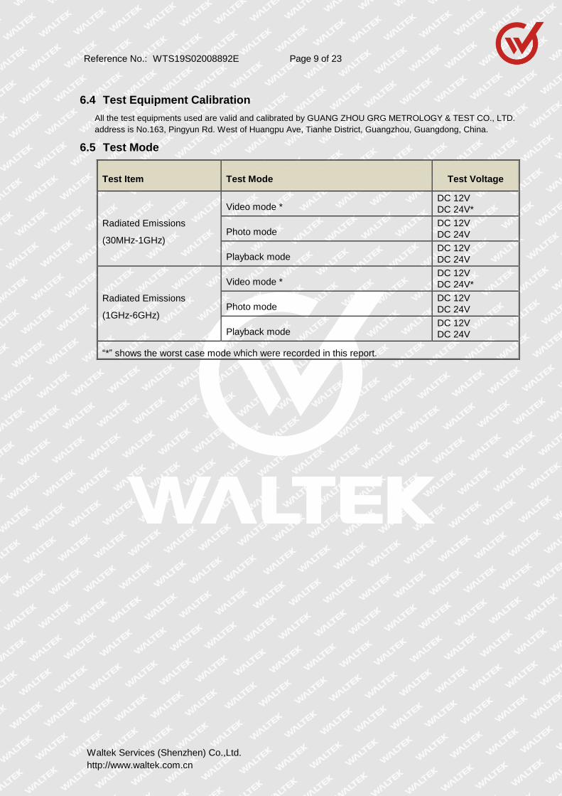
6.4 Test Equipment Calibration
All the test equipments used are valid and calibrated by GUANG ZHOU GRG METROLOGY & TEST CO., LTD.
address is No.163, Pingyun Rd. West of Huangpu Ave, Tianhe District, Guangzhou, Guangdong, China.
6.5 Test Mode
Test Item Test Mode Test Voltage
Radiated Emissions
(30MHz-1GHz)
Video mode * DC 12V
DC 24V*
Photo mode DC 12V
DC 24V
Playback mode DC 12V
DC 24V
Radiated Emissions
(1GHz-6GHz)
Video mode * DC 12V
DC 24V*
Photo mode DC 12V
DC 24V
Playback mode DC 12V
DC 24V
“*” shows the worst case mode which were recorded in this report.

Reference No.: WTS19S02008892E Page 10 of 23
Waltek Services (Shenzhen) Co.,Ltd.
http://www.waltek.com.cn
7 Emission Test Results
7.1 Radiation Emission, 30MHz to 1000MHz
Test Requirement ................ : FCC PART 15, SUBPART B
Test Method ........................ : ANSI C63.4
Test Result .......................... : Pass
Frequency Range ................ : 30MHz to 1000MHz
Class. : Class B
Limit ....................................... :
Frequency (MHz) Distance
(Meter)
Limit (dBμV/m)
Quasi-peak
30 to 88 3 40
88 to 216 3 43.5
216 to 960 3 46
960 to 1000 3 54
7.1.1 E.U.T. Operation
Operating Environment:
Temperature ....................... : 22.5C
Humidity .............................. : 52.6%RH
Atmospheric Pressure ........ : 101.8kPa
EUT Operation .................... : Refer to section 6.5.
7.1.2 Block Diagram of Test Setup
The radiated emission tests were performed in the 3m Semi- Anechoic Chamber test site, using
the setup accordance with the ANSI C63.4.
3m
0.8m
Semi-anechoic 3m Chamber
EUT
Spectrum
Analyzer
PC
System
AMP Combining
Network
Turn Table
Antenna Elevation Varies From 1 to 4 m
Turn Table From 0°to 360°

Reference No.: WTS19S02008892E Page 11 of 23
Waltek Services (Shenzhen) Co.,Ltd.
http://www.waltek.com.cn
7.1.3 Measurement Data
The maximised peak emissions from the EUT was scanned and measured for both the Antenna Vertical Polarization and Antenna Horizontal Polarization. Quasi-peak measurements were performed if peak emissions were within 6dB of the Quasi-peak limit line.
7.1.4 Radiated Emission Test Data, 30MHz to 1000MHz
Antenna Polarization: Vertical

Reference No.: WTS19S02008892E Page 12 of 23
Waltek Services (Shenzhen) Co.,Ltd.
http://www.waltek.com.cn
Antenna Polarization: Horizontal

Reference No.: WTS19S02008892E Page 13 of 23
Waltek Services (Shenzhen) Co.,Ltd.
http://www.waltek.com.cn
7.2 Radiation Emission, Above 1000MHz
Test Requirement ............... : FCC PART 15, SUBPART B
Test Method ........................ : ANSI C63.4
Test Result .......................... : Pass
Frequency Range ................ : Above 1GHz
Class. : Class B
Limit. .................................. :
Frequency Range (MHz)
Distance (Meter)
Average Limit dB(uV/m)
Peak Limit (dBuV/m)
Above 1GHz 3 54 74
7.2.1 E.U.T. Operation
Operating Environment:
Temperature ....................... : 22.5C
Humidity .............................. : 52.6%RH
Atmospheric Pressure ........ : 101.8kPa
EUT Operation .................... : Refer to section 6.5.
7.2.2 Block Diagram of Test Setup
The radiated emission tests were performed in the 3m Semi- Anechoic Chamber test site, using
the setup accordance with the ANSI C63.4.
7.2.3 Measurement Data
The maximised peak emissions from the EUT was scanned and measured for both the Antenna Vertical Polarization and Antenna Horizontal Polarization. Average measurements were performed if peak emissions were within 6dB of the average limit line
3m
0.8m
Semi-anechoic 3m Chamber
EUT
Antenna Elevation Varies From 1 to 4 m
Turn Table From 0°to 360°
Spectrum
Analyzer
PC
System
AMP Combining
Network
Turn Table

Reference No.: WTS19S02008892E Page 14 of 23
Waltek Services (Shenzhen) Co.,Ltd.
http://www.waltek.com.cn
7.2.4 Radiated Emission test data, Above 1000MHz
Antenna Polarization: Vertical

Reference No.: WTS19S02008892E Page 15 of 23
Waltek Services (Shenzhen) Co.,Ltd.
http://www.waltek.com.cn
Antenna Polarization: Horizontal

Reference No.: WTS19S02008892E Page 16 of 23
Waltek Services (Shenzhen) Co.,Ltd.
http://www.waltek.com.cn
8 Photographs – Test Setup
8.1 Photograph – Radiated Emission Test Setup For 30MHz-1000MHz
8.2 Photograph – Radiated Emission Test Setup For Above 1GHz

Reference No.: WTS19S02008892E Page 17 of 23
Waltek Services (Shenzhen) Co.,Ltd.
http://www.waltek.com.cn
9 Photographs – Constructional Details
9.1 EUT – Appearance View

Reference No.: WTS19S02008892E Page 18 of 23
Waltek Services (Shenzhen) Co.,Ltd.
http://www.waltek.com.cn

Reference No.: WTS19S02008892E Page 19 of 23
Waltek Services (Shenzhen) Co.,Ltd.
http://www.waltek.com.cn

Reference No.: WTS19S02008892E Page 20 of 23
Waltek Services (Shenzhen) Co.,Ltd.
http://www.waltek.com.cn

Reference No.: WTS19S02008892E Page 21 of 23
Waltek Services (Shenzhen) Co.,Ltd.
http://www.waltek.com.cn

Reference No.: WTS19S02008892E Page 22 of 23
Waltek Services (Shenzhen) Co.,Ltd.
http://www.waltek.com.cn

Reference No.: WTS19S02008892E Page 23 of 23
Waltek Services (Shenzhen) Co.,Ltd.
http://www.waltek.com.cn
======End of Report======