references tesys circuit-breakers - elektrykasklep.pl227960,katalog43.pdf · 3/31 schneider...
TRANSCRIPT
3/31
Schneider Electric
3
3.1
TeSys circuit-breakers
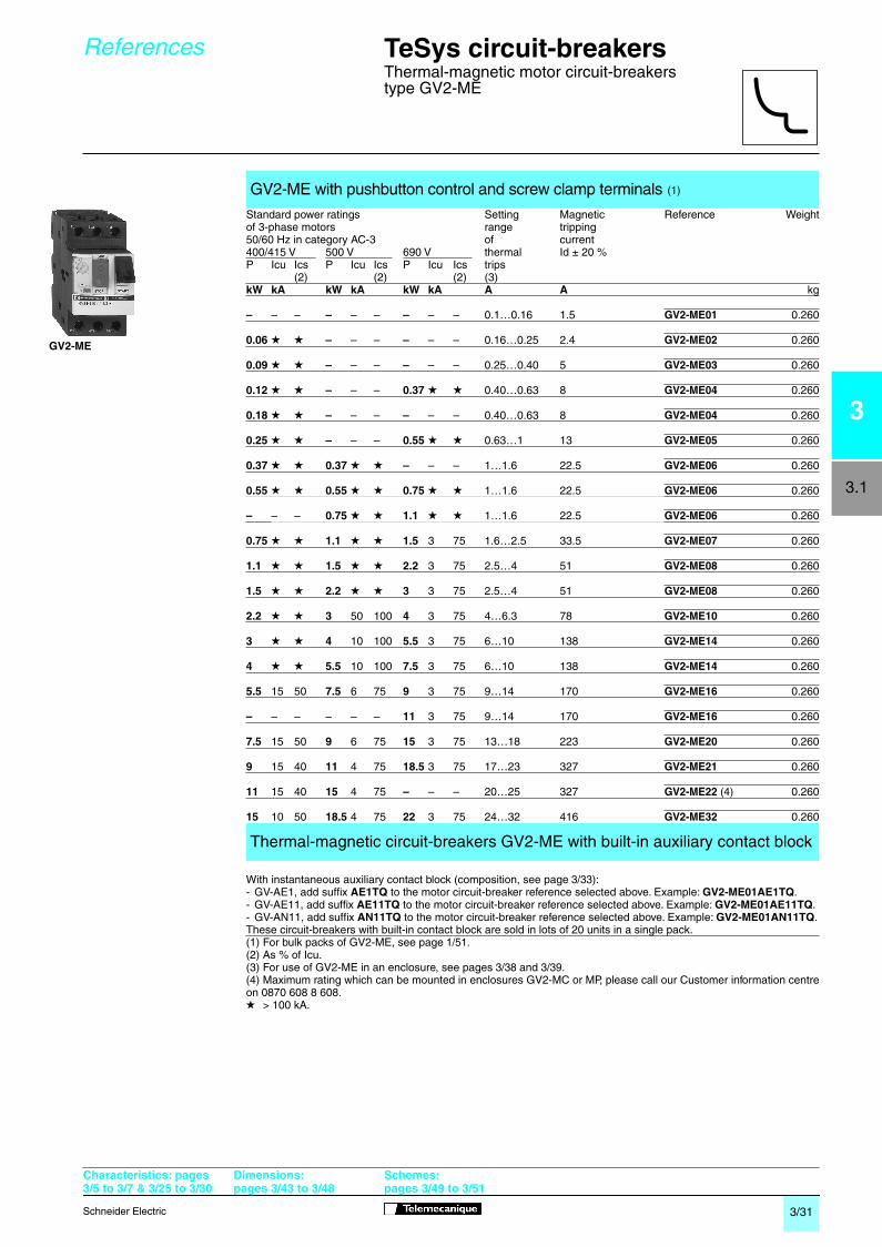
Thermal-magnetic motor circuit-breakers type GV2-ME
With instantaneous auxiliary contact block (composition, see page
3/33
):- GV-AE1, add suffix
AE1TQ
to the motor circuit-breaker reference selected above. Example:
GV2-ME01AE1TQ
.- GV-AE11, add suffix
AE11TQ
to the motor circuit-breaker reference selected above. Example:
GV2-ME01AE11TQ
.- GV-AN11, add suffix
AN11TQ
to the motor circuit-breaker reference selected above. Example:
GV2-ME01AN11TQ
.
These circuit-breakers with built-in contact block are sold in lots of 20 units in a single pack.(1) For bulk packs of GV2-ME, see page
1/51.
(2) As % of Icu.(3) For use of GV2-ME in an enclosure, see pages
3/38
and
3/39.
(4) Maximum rating which can be mounted in enclosures GV2-MC or MP, please call our Customer information centreon 0870 608 8 608.
GV2-ME with pushbutton control and screw clamp terminals
(1)
Standard power ratings Setting Magnetic Reference Weightof 3-phase motors range tripping50/60 Hz in category AC-3 of current400/415 V 500 V 690 V thermal Id ± 20 %P Icu Ics P Icu Ics P Icu Ics trips
(2) (2) (2) (3)
kW kA kW kA kW kA A A
kg
–
– –
–
– –
–
– – 0.1…0.16 1.5
GV2-ME01
0.260
0.06
g g
–
– –
–
– – 0.16…0.25 2.4
GV2-ME02
0.260
0.09
g g
–
– –
–
– – 0.25…0.40 5
GV2-ME03
0.260
0.12
g g
–
– –
0.37
g g
0.40…0.63 8
GV2-ME04
0.260
0.18
g g
–
– –
–
– – 0.40…0.63 8
GV2-ME04
0.260
0.25
g g
–
– –
0.55
g g
0.63…1 13
GV2-ME05
0.260
0.37
g g
0.37
g g
–
– – 1…1.6 22.5
GV2-ME06
0.260
0.55
g g
0.55
g g
0.75
g g
1…1.6 22.5
GV2-ME06
0.260
–
– –
0.75
g g
1.1
g g
1…1.6 22.5
GV2-ME06
0.260
0.75
g g
1.1
g g
1.5
3 75 1.6…2.5 33.5
GV2-ME07
0.260
1.1
g g
1.5
g g
2.2
3 75 2.5…4 51
GV2-ME08
0.260
1.5
g g
2.2
g g
3
3 75 2.5…4 51
GV2-ME08
0.260
2.2
g g
3
50 100
4
3 75 4…6.3 78
GV2-ME10
0.260
3
g g
4
10 100
5.5
3 75 6…10 138
GV2-ME14
0.260
4
g g
5.5
10 100
7.5
3 75 6…10 138
GV2-ME14
0.260
5.5
15 50
7.5
6 75
9
3 75 9…14 170
GV2-ME16
0.260
–
– – – – –
11
3 75 9…14 170
GV2-ME16
0.260
7.5
15 50
9
6 75
15
3 75 13…18 223
GV2-ME20
0.260
9
15 40
11
4 75
18.5
3 75 17…23 327
GV2-ME21
0.260
11
15 40
15
4 75
–
– – 20…25 327
GV2-ME22
(4)
0.260
15
10 50
18.5
4 75
22
3 75 24…32 416
GV2-ME32
0.260
Thermal-magnetic circuit-breakers GV2-ME with built-in auxiliary contact block
g
> 100 kA.
References
GV2-ME
Characteristics: pages3/5 to 3/7 & 3/25 to 3/30
Dimensions:pages 3/43 to 3/48
Schemes:pages 3/49 to 3/51
3/31-32 Page 31 Monday, October 29, 2001 3:17 PM
3/32
Schneider Electric
3
3.1
References
TeSys circuit-breakers
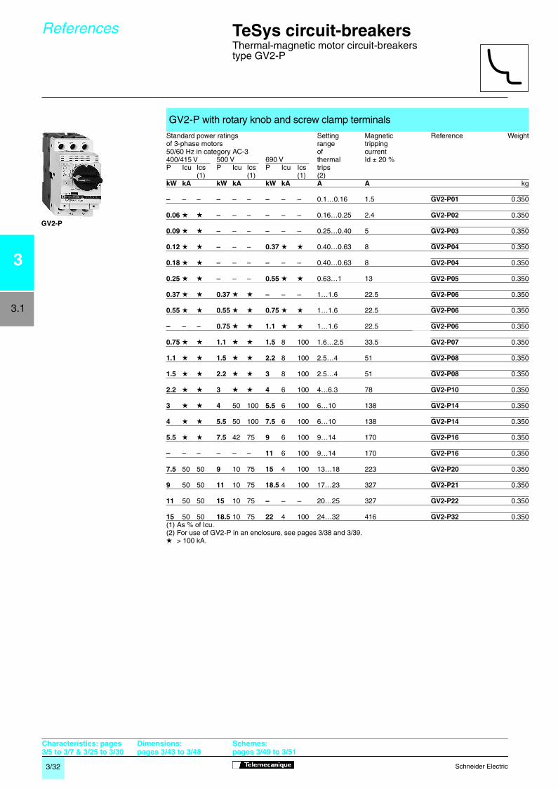
Thermal-magnetic motor circuit-breakers type GV2-P
(1) As % of Icu.(2) For use of GV2-P in an enclosure, see pages
3/38
and
3/39.
GV2-P with rotary knob and screw clamp terminals
Standard power ratings Setting Magnetic Reference Weightof 3-phase motors range tripping50/60 Hz in category AC-3 of current400/415 V 500 V 690 V thermal Id ± 20 %P Icu Ics P Icu Ics P Icu Ics trips
(1) (1) (1) (2)
kW kA kW kA kW kA A A
kg
–
– –
–
– –
–
– – 0.1…0.16 1.5
GV2-P01
0.350
0.06
g g
–
– –
–
– – 0.16…0.25 2.4
GV2-P02
0.350
0.09
g g
–
– –
–
– – 0.25…0.40 5
GV2-P03
0.350
0.12
g g
–
– –
0.37
g g
0.40…0.63 8
GV2-P04
0.350
0.18
g g
–
– –
–
– – 0.40…0.63 8
GV2-P04
0.350
0.25
g g
–
– –
0.55
g g
0.63…1 13
GV2-P05
0.350
0.37
g g
0.37
g g
–
– – 1…1.6 22.5
GV2-P06
0.350
0.55
g g
0.55
g g
0.75
g g
1…1.6 22.5
GV2-P06
0.350
–
– –
0.75
g g
1.1
g g
1…1.6 22.5
GV2-P06
0.350
0.75
g g
1.1
g g
1.5
8 100 1.6…2.5 33.5
GV2-P07
0.350
1.1
g g
1.5
g g
2.2
8 100 2.5…4 51
GV2-P08
0.350
1.5
g g
2.2
g g
3
8 100 2.5…4 51
GV2-P08
0.350
2.2
g g
3
g g
4
6 100 4…6.3 78
GV2-P10
0.350
3
g g
4
50 100
5.5
6 100 6…10 138
GV2-P14
0.350
4
g g
5.5
50 100
7.5
6 100 6…10 138
GV2-P14
0.350
5.5
g g
7.5
42 75
9
6 100 9…14 170
GV2-P16
0.350
–
– – – – –
11
6 100 9…14 170
GV2-P16
0.350
7.5
50 50
9
10 75
15
4 100 13…18 223
GV2-P20
0.350
9
50 50
11
10 75
18.5
4 100 17…23 327
GV2-P21
0.350
11
50 50
15
10 75
–
– – 20…25 327
GV2-P22
0.350
15
50 50
18.5
10 75
22
4 100 24…32 416
GV2-P32
0.350
g
> 100 kA.
Characteristics: pages3/5 to 3/7 & 3/25 to 3/30
Dimensions:pages 3/43 to 3/48
Schemes:pages 3/49 to 3/51
GV2-P
3
3/31-32 Page 32 Monday, October 29, 2001 3:18 PM

3/33
Schneider Electric
3
3.1
TeSys circuit-breakers
Thermal-magnetic motor circuit-breakers type GV2-ME
Pushbutton control
(1) For connection of conductors from 1 to 1.5 mm
2
the use of a cable end reducer LA9-D99 is recommended.
Thermal-magnetic circuit-breakers GV2-ME with spring terminal connections
(1)
Standard power ratings Setting Magnetic Reference Weightof 3-phase motors range of tripping50/60 Hz in category AC-3 thermal current400/415 V 500 V trips Id ± 20 %P Icu Ics (2) P Icu Ics (2)
kW kA kW kA A A
kg
–
– –
–
– – 0.1…0.16 1.5
GV2-ME013
0.280
0.06
g g
–
– – 0.16…0.25 2.4
GV2-ME023
0.280
0.09
g g
–
– – 0.25…0.40 5
GV2-ME033
0.280
0.12
g g
–
– – 0.40…0.63 8
GV2-ME043
0.280
0.18
g g
0.25
g g
0.37
g g
0.63…1 13
GV2-ME053
0.280
0.37
g g
0.37
g g
0.37
g g
1…1.6 22.5
GV2-ME063
0.280
0.55
g g
0.55
g g
0.75
g g
0.75
g g
1.1
g g
1.6…2.5 33.5
GV2-ME073
0.280
1.1
g g
1.5
g g
2.5…4 51
GV2-ME083
0.280
1.5
g g
2.2
g g
2.2
g g
3
50 100 4…6.3 78
GV2-ME103
0.280
3
g g
4
10 100 6…10 138
GV2-ME143
0.280
4
g g
5.5
10 100
5.5
15 50
7.5
6 75 9…14 170
GV2-ME163
0.280
7.5
15 50
9
6 75 13…18 223
GV2-ME203
0.280
9
15 40
11
4 75 17…23 327
GV2-ME213
0.260
11
15 40
11
15 40
15
4 75 20…25 327
GV2-ME223
0.260
Contact blocks
Description Mounting Max. Type of contacts
Sold in
Unit Weightnumber
lots of
reference kg
Instantaneous
Front 1 N/O + N/C
10
GV-AE113
0.030
auxiliary
N/O + N/O
10
GV-AE203
0.030
contacts
LH 2 N/O + N/C
1
GV-AN113
0.060side N/O + N/O
1
GV-AN203
0.060
Accessory
Description Application
Sold in
Unit Weight
lots of
reference kg
Cable end
For connection of
20
LA9-D99
–
reducer
(3) conductors from 1 to 1.5 mm
2
(2) As % of Icu.
g
> 100 kA(3) 22 supplied with each circuit-breaker as standard.
References
GV2-ME
pppppppp
3
LA9-D99
Characteristics: pages3/5 to 3/7 & 3/25 to 3/30
Dimensions:pages 3/43 to 3/48
Schemes:pages 3/49 to 3/51
3/33 Page 33 Monday, October 29, 2001 10:54 AM
3/34
Schneider Electric
3
3.1
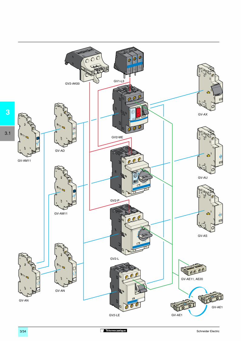
GV2-AK00GV1-L3
GV-AD
GV-AM11
GV-AM11
GV-AN
GV-AN
GV2-P
GV2-ME
GV-AX
GV-AU
GV-AS
GV-AE1
GV-AE1
GV-AE11, AE20
GV2-L
GV2-LE
3/34-35 Page 34 Monday, October 29, 2001 10:55 AM

3/35
Schneider Electric
3
3.1
TeSys circuit-breakers
Thermal-magnetic and magnetic motor circuit-breakers type GV2 with screw clamp terminalsAccessories
Undervoltage trip, INRS
(can only be mounted on GV2-ME)
Safety device for dangerous machines,
conforming to INRS and VDE 0113
(1) Mounting of a
GV-AE
contact block or a
GV2-AK00
visible isolation block on
GV2-P
and
GV2-L
.(2) Choice of N/C or N/O contact operation, depending on which way round the reversible block is mounted.(3) The
GV-AD
is always mounted next to the circuit-breaker.(4) To order an undervoltage trip: replace the dot (
p
) in the reference with a
U
, example:
GV-AU025
. To order a shunttrip: replace the dot (
p
) in the reference with an
S
, example:
GV-AS025
.(5) Visible isolation of the 3 poles upstream of circuit-breaker
GV2-P
and
GV2-L
.
Contact blocks with screw clamp terminals
Description Mounting Maximum Type of contacts
Sold in
Unit Weightnumber
lots of
reference kg
Instantaneous
Front (1) 1 N/O or N/C (2)
10
GV-AE1
0.015
auxiliary
N/O + N/C
10
GV-AE11
0.020
contacts
N/O + N/O
10
GV-AE20
0.020Side 2 N/O + N/C
1
GV-AN11
0.050(LH) N/O + N/O
1
GV-AN20
0.050
Fault signalling
Side (3) 1 N/O + N/O
1
GV-AD1010
0.055
contact +
(LH) (fault) + N/C
1
GV-AD1001
0.055
instantaneous
N/C + N/O
1
GV-AD0110
0.055
auxiliary contact
(fault) + N/C
1
GV-AD0101
0.055
Short-circuitsignalling
Side 1 C/O
1
GV-AM11
0.045
contact
(LH) common point
Electric trips with screw clamp terminals
Mounting Voltage Reference Weightkg
Undervoltage or shunt trips
(4)
Side
24 V 50 Hz
GV-A
pppp
025
0.105(1 block on RH side 60 Hz
GV-A
pppp
026
0.105of circuit-breaker) 48 V 50 Hz
GV-A
pppp
055
0.10560 Hz
GV-A
pppp
056
0.105100 V 50 Hz
GV-A
pppp
107
0.105100…110 V 60 Hz
GV-A
pppp
107
0.105110…115 V 50 Hz
GV-A
pppp
115
0.10560 Hz
GV-A
pppp
116
0.105120…127 V 50 Hz
GV-A
pppp
125
0.105127 V 60 Hz
GV-A
pppp
115
0.105200 V 50 Hz
GV-A
pppp
207
0.105200 V…220 V 60 Hz
GV-A
pppp
207
0.105220 V…240 V 50 Hz
GV-A
pppp
225
0.10560 Hz
GV-A
pppp
226
0.105380 V…400 V 50 Hz
GV-A
pppp
385
0.10560 Hz
GV-A
pppp
386
0.105415 V…440 V 50 Hz
GV-A
pppp
415
0.105415 V 60 Hz
GV-A
pppp
416
0.105440 V 60 Hz
GV-A
pppp
385
0.105480 V 60 Hz
GV-A
pppp
415
0.105500 V 50 Hz
GV-A
pppp
505
0.105600 V 60 Hz
GV-A
pppp
505
0.105
Side
110…115 V 50 Hz
GV-AX115
0.110(1 block on RH side 60 Hz
GV-AX116
0.110of circuit-breaker 127 V 60 Hz
GV-AX115
0.110GV2-ME) 220…240 V 50 Hz
GV-AX225
0.11060 Hz
GV-AX226
0.110380…400 V 50 Hz
GV-AX385
0.11060 Hz
GV-AX386
0.110415…440 V 50 Hz
GV-AX415
0.110440 V 60 Hz
GV-AX385
0.110
Add-on contact blocks with screw clamp terminals
Description Mounting Maximum Reference Weightnumber kg
Visible isolation
Front (1) 1
GV2-AK00
0.150
block
(5)
Limiters
At top 1
GV1-L3
0.130(
GV2-ME
and
GV2-P
)
Independent 1
LA9-LB920
0.320
References
Characteristics: pages3/5 to 3/7 & 3/25 to 3/30
Dimensions:pages 3/43 to 3/48
Schemes:pages 3/49 to 3/51
LA9-LB920
3/34-35 Page 35 Monday, October 29, 2001 10:55 AM

3/36
Schneider Electric
3
3.1
GV1-G09
GV2-G05
LA9-E07
GV2-AF3 GV2-AF4
LAD-31GV2-G454
GV2-AF01
GV2-AP0 2
LAD-31
O
TRIP.TRIP.
RESET RESET
GV2-GA01
GV2-G454GV2-G254 GV2-G254
GV1-G10
GV1-G02
GK2-AF01
GV2-V03
GV2-AF02
3/36-37 Page 36 Monday, October 29, 2001 10:56 AM

3/37
Schneider Electric
3
3.1
TeSys circuit-breakers
Thermal-magnetic and magnetic motor circuit-breakers type GV2 with screw clamp terminalsAccessories
(1) Check with requirements of local Isolation standards before use.
Accessories
Description Application
Sold in
Unit Weight
lots of reference
kg
Adapter plate
For mounting a GV2-ME
10
GV2-AF02
0.021or GV2-LE by screw fixingFor mounting a GV2-ME or
10
LAD-31
0.040GV2-P and contactor LC1-D09 toD38 with front faces aligned
Height compensation plate
7.5 mm
10
GV1-F03
0.003
Combination block
Between GV2 and contactor
10
GV2-AF01
0.020LC1-K or LP1-K Between GV2 and contactor
10
GV2-AF3
0.016LC1-D09…D38Between GV2 mounted
10
GV2-AF4
0.016on LAD-31 andcontactor LC1-D09…D38
Motor starter
With 3-pole connection
1
GK2-AF01
0.120
adapter plate
for mounting a GV2 andan LC1-D09 to D25 contactor
Description Application Pitch
Reference
Weight
mm
kg
Sets of 3-pole
2 tap-offs 45
GV2-G245
0.036
63 A busbars
54
GV2-G254
0.03872
GV2-G272
0.0423 tap-offs 45
GV2-G345
0.05854
GV2-G354
0.0604 tap-offs 45
GV2-G445
0.07754
GV2-G454
0.08572
GV2-G472
0.0945 tap-offs 54
GV2-G554
0.100Description Application
Sold in Unit
Weight
lots of reference
kg
Protective end cover
(1) For unused busbar outlets
5
GV1-G10
0.005
Terminal blocks
for Connection from the top
1
GV1-G09
0.040supply to one or more Can be fitted with current limiter
1
GV2-G05
0.115GV2-G
busbar sets GV1-L3 (GV2-ME and GV2-P)
Cover for terminal block
For mounting in
10
LA9-E07
0.005modular panels
Flexible 3-pole connection
Centre distance between
10
GV1-G02
0.013for connecting a GV2 mounting rails: 100…120 mmto an LC1-D09…D25contactor
Set of connections
For connecting GV2-ME
10
GV2-GA01
0.045upstream/downstream to a printed circuit board
Clip-in marker holders
For GV2-P, GV2-L, GV2-LE
100
LA9-D92 (1)
0.001(supplied with each and GV2-RT (8 x 22 mm)circuit-breaker)
Padlockable external operator
Description
Reference Weightkg
For GV2-P and GV2-L Padlocking in “On” and “Off” position
GV2-AP01
0.200(150 to 290 mm) Black handle, blue legend plate, IP 54
Padlocking in “Off” position
GV2-AP02
0.200Red handle, yellow legend plate, IP 54
For GV2-LE Padlocking in “On” and “Off” position
GV2-AP03
0.280Black handle, blue legend plate, IP 54
Padlocking device
For all GV2 devices For use with up to 6 padlocks (not supplied),
GV2-V03
0.130Ø 6 mm shank max.
References
Dimensions:pages 3/43 to 3/48
3/36-37 Page 37 Monday, October 29, 2001 10:56 AM

3/38
Schneider Electric
3
3.1
GV2-MC
GV2-SN
GV2-E01
GV2-K011
GV2-V01
GV2-MP
GV2-CP
GV2-K04
3/38-39 Page 38 Monday, October 29, 2001 10:59 AM

3/39
Schneider Electric
3
3.1
TeSys circuit-breakers
Enclosed thermal-magnetic motor circuit-breakerstype GV2-ME and accessories, assembled by user
Thermal-magnetic motor circuit-breakers and accessories: see pages
3/31
and
3/33
.
The motor starter comprising an enclosed motor circuit-breaker GV2-ME conforms to IEC/EN 60947-4-1.
Ithe
(1) The GV2-MCK04 enclosure has a GV2-K04 mushroom head Stop pushbutton fitted as standard.(2) Supplied with IP 55 sealing kit. For use with GV2-M
p
01.(3) Padlockable in “Off” position using Ø 4 to 8 mm shank padlocks.
Enclosed thermal-magnetic motor circuit-breakers GV2-ME
GV2- ME01 ME02 ME03 ME04 ME05 ME06 ME07 ME08 ME10 ME14 ME16 ME20 ME21 ME22
(A) 0.16 0.25 0.4 0.63 1 1.6 2.5 4 6.3 9 13 17 21 23
Enclosures for thermal-magnetic motor circuit-breakers GV2-ME
Type Degree of protection Possible attachments Reference Weighton side of GV2-MELeft Right kg
Surface
IP 41 1 1
GV2-MC01
0.290mounting Double,insulated with IP 55 1 1
GV2-MC02
0.300protective or
GV2-MCK04
(1)
0.420conductor.Sealable IP 55 for 1 1
GV2-MC03
0.300cover temperature < + 5 ˚C
Flush
, IP 41 (front face) 1 1
GV2-MP01
0.115
mounting
IP 41 (reduced flush mounting) – 1
GV2-MP03
0.115with protective IP 55 (front face) 1 1
GV2-MP02
0.130conductor IP 55 (reduced flush mounting) – 1
GV2-MP04
0.130
Front plate
For direct control,
through a panel IP 55
GV2-CP21
0.800of a chassis-mounted GV2-ME
Accessories common to all enclosures
(to be ordered separately)
Description
Sold in Unit
Weight
lots of reference
kg
Padlocking device
(2) 1 to 3 padlocks
1
GV2-V01
0.075for GV2-ME operator (padlocking is only Ø 4 to 8 mmpossible in “O” position)
Mushroom
Spring return (2)
1
GV2-K011
0.052
head “Stop”
Latching (2) Key release
1
GV2-K021
0.160
pushbutton
IP 55 key n˚ 455Ø
40 mm,red
Turn to
1
GV2-K031
0.115release
1
GV2-K04
(3)
0.120
Sealing kit
For enclosures IP 55
10
GV2-E01
0.012and front plate IP 55
for
θ
< + 5 ˚C
10
GV2-E02
0.012
Neutral terminal
100
AB1-VV635UBL
0.015
Partition
50
AB1-AC6BL
0.003Description Voltage Colour
Sold in Unit
Weight
V
lots of reference
kg
Neon
110 Green
10
GV2-SN13
0.019
indicator
Red
10
GV2-SN14
0.019
light
Orange
10
GV2-SN15
0.019Clear
10
GV2-SN17
0.019220/240 Green
10
GV2-SN23
0.019Red
10
GV2-SN24
0,019Orange
10
GV2-SN25
0,019Clear
10
GV2-SN27
0,019380/440 Green
10
GV2-SN33
0.019Red
10
GV2-SN34
0.019Orange
10
GV2-SN35
0.019Clear
10
GV2-SN37
0.019
References
3/38-39 Page 39 Monday, October 29, 2001 10:59 AM
3/40
Schneider Electric
3
3.1
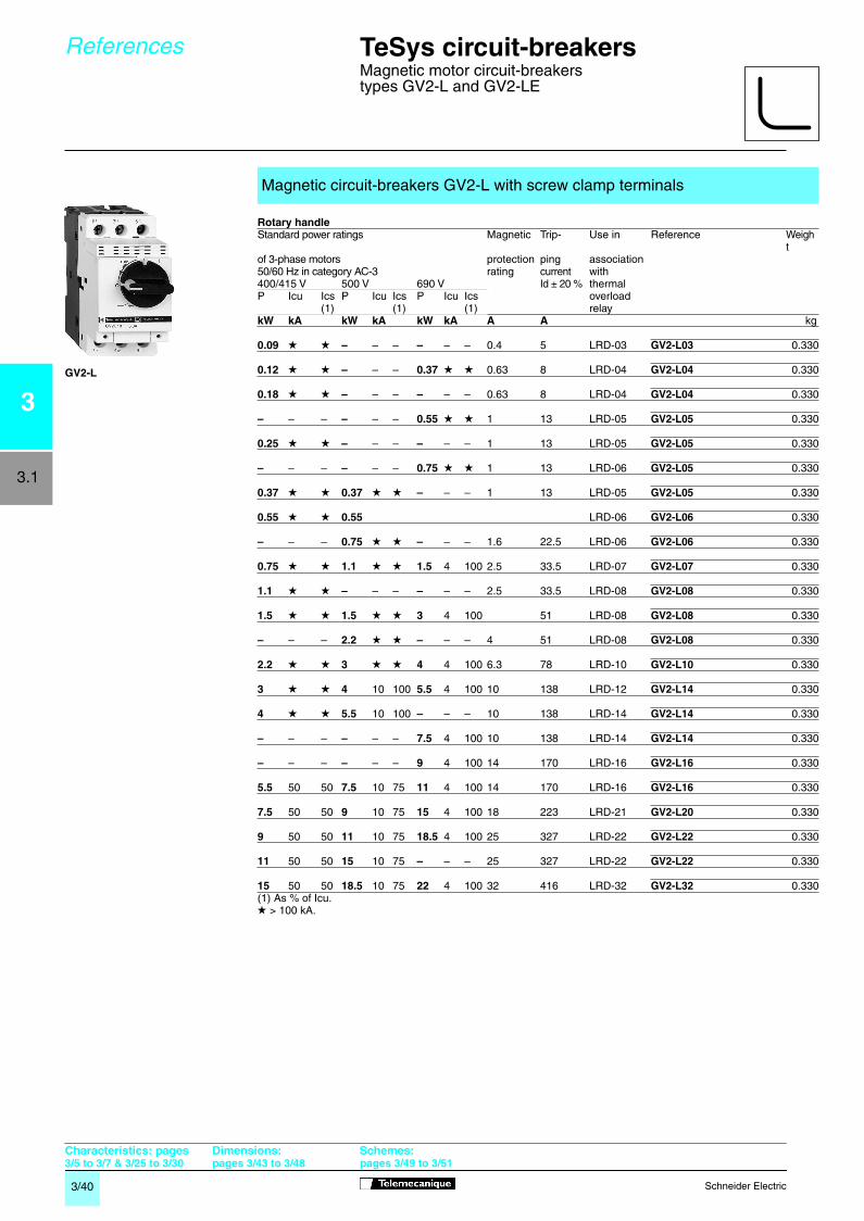
(1) As % of Icu.
Magnetic circuit-breakers GV2-L with screw clamp terminals
Rotary handle
Standard power ratings Magnetic Trip- Use in Reference
Weight
of 3-phase motors protection ping association50/60 Hz in category AC-3 rating
current
with 400/415 V 500 V 690 V
Id ± 20 %
thermalP Icu Ics P Icu Ics P Icu Ics overload
(1) (1) (1) relay
kW kA kW kA kW kA A A
kg
0.09
g g
–
– –
–
– – 0.4 5 LRD-03
GV2-L03
0.330
0.12
g g
–
– –
0.37
g g
0.63 8 LRD-04
GV2-L04
0.330
0.18
g g
–
– –
–
– – 0.63 8 LRD-04
GV2-L04
0.330
–
– –
–
– –
0.55
g g
1 13 LRD-05
GV2-L05
0.330
0.25
g g
–
– –
–
– – 1 13 LRD-05
GV2-L05
0.330
–
– –
–
– –
0.75
g g
1 13 LRD-06
GV2-L05
0.330
0.37
g g
0.37
g g
–
– – 1 13 LRD-05
GV2-L05
0.330
0.55
g g
0.55
LRD-06
GV2-L06
0.330
–
– –
0.75
g g
–
– – 1.6 22.5 LRD-06
GV2-L06
0.330
0.75
g g
1.1
g g
1.5
4 100 2.5 33.5 LRD-07
GV2-L07
0.330
1.1
g g
–
– –
–
– – 2.5 33.5 LRD-08
GV2-L08
0.330
1.5
g g
1.5
g g
3
4 100 51 LRD-08
GV2-L08
0.330
–
– –
2.2
g g
–
– – 4 51 LRD-08
GV2-L08
0.330
2.2
g g
3
g g
4
4 100 6.3 78 LRD-10
GV2-L10
0.330
3
g g
4
10 100
5.5
4 100 10 138 LRD-12
GV2-L14
0.330
4
g g
5.5
10 100
–
– – 10 138 LRD-14
GV2-L14
0.330
–
– –
–
– –
7.5
4 100 10 138 LRD-14
GV2-L14
0.330
–
– –
–
– –
9
4 100 14 170 LRD-16
GV2-L16
0.330
5.5
50 50
7.5
10 75
11
4 100 14 170 LRD-16
GV2-L16
0.330
7.5
50 50
9
10 75
15
4 100 18 223 LRD-21
GV2-L20
0.330
9
50 50
11
10 75
18.5
4 100 25 327 LRD-22
GV2-L22
0.330
11
50 50
15
10 75
–
– – 25 327 LRD-22
GV2-L22
0.330
15
50 50
18.5
10 75
22
4 100 32 416 LRD-32
GV2-L32
0.330
g
> 100 kA.
References
TeSys circuit-breakers
Magnetic motor circuit-breakerstypes GV2-L and GV2-LE
Characteristics: pages 3/5 to 3/7 & 3/25 to 3/30
Dimensions:pages 3/43 to 3/48
Schemes:pages 3/49 to 3/51
GV2-L
3/40-41 Page 40 Monday, October 29, 2001 11:00 AM

3/41
Schneider Electric
3
3.1
(1) As % of Icu. TeSys protection components
Magnetic circuit-breakers GV2-LE with screw clamp terminals
Rocker lever
Standard power ratings Magnetic Trip- Use in Reference
Weight
of 3-phase motors protection ping association50/60 Hz in category AC-3 rating
current
with 400/415 V 500 V 690 V
Id ± 20 %
thermalP Icu Ics P Icu Ics P Icu Ics overload
(1) (1) (1) relay
kW kA kW kA kW kA A A
kg
0.06
g g
–
– –
–
– – 0.4 5 LR2-K0302
GV2-LE03
0.330
0.09
g g
–
– –
–
– – 0.4 5 LR2-K0304
GV2-LE03
0.330
0.12
g g
–
– –
0.37
g g
0.63 8 LR2-K0304
GV2-LE04
0.330
0.18
g g
–
– –
–
– – 0.63 8 LR2-K0305
GV2-LE04
0.330
–
– –
–
– –
0.55
g g
1 13 LR2-K0305
GV2-LE05
0.330
0.25
g g
–
– –
–
– – 1 13 LR2-K0306
GV2-LE05
0.330
–
– –
–
– –
0.75
g g
1 13 LR2-K0306
GV2-LE05
0.330
0.37
g g
0.37
g g
–
– – 1 13 LR2-K0306
GV2-LE05
0.330
0.55
g g
0.55
g g
1.1
g g
1.6 22.5 LR2-K0307
GV2-LE06
0.330
–
– –
0.75
g g
–
– – 1.6 22.5 LR2-K0307
GV2-LE06
0.330
0.75
g g
1.1
g g
1.5
3 75 2.5 33.5 LR2-K0308
GV2-LE07
0.330
1.1
g g
–
– –
–
– – 2.5 33.5 LR2-K0308
GV2-LE08
0.330
1.5
g g
1.5
g g
3
3 75 4 51 LR2-K0310
GV2-LE08
0.330
–
– –
2.2
g g
–
– – 4 51 LR2-K0312
GV2-LE08
0.330
2.2
g g
3
50 100
4
3 75 6.3 78 LR2-K0312
GV2-LE10
0.330
3
g g
4
10 100
5.5
3 75 10 138 LR2-K0314
GV2-LE14
0.330
4
g g
5.5
10 100
–
– – 10 138 LR2-K0316
GV2-LE14
0.330
–
– –
–
– –
7.5
3 75 10 138 LRD-14
GV2-LE14
0.330
–
– –
–
– –
9
3 75 14 170 LRD-16
GV2-LE16
0.330
5.5
15 50
7.5
6 75
11
3 75 14 170 LR2-K0321
GV2-LE16
0.330
7.5
15 50
9
6 75
15
3 75 18 223 LRD-21
GV2-LE20
0.330
9
15 40
11
4 75
18.5
3 75 25 327 LRD-22
GV2-LE22
0.330
11
15 40
15
4 75
–
– – 25 327 LRD-22
GV2-LE22
0.330
15
10 50
18.5
4 75
22
3 75 32 416 LRD-32
GV2-LE32
0.330
g
> 100 kA.
TeSys circuit-breakers
Magnetic motor circuit-breakerstypes GV2-L and GV2-LE
References
Characteristics: pages 3/5 to 3/7 & 3/25 to 3/30
Dimensions:pages 3/43 to 3/48
Schemes:pages 3/49 to 3/51
GV2-LE
3/40-41 Page 41 Monday, October 29, 2001 11:01 AM

3/42
Schneider Electric
3
3.1
TeSys circuit-breakers
Thermal magnetic circuit-breakerstype GV2-RT
(1)
Control by rocker lever
Control by rocker lever
(1) Characteristics of GV2-RT identical to those of GV2-ME except for tripping current (id).(2) Other accessories such as mounting, cabling and marking accessories are identical to those used for GV2-MEmotor circuit-breakers, see page
3/39
.
For motors with high current peak on starting
Standard power ratings Setting Magnetic Reference Weightof 3-phase motors range of tripping50/60 Hz in category AC-3 thermal current220 400 trips Id ± 20 %230 V 415 V 440 V 500 V 690 V
kW kW kW kW kW A A
kg
0.06 0.09 0.09 – – 0.25…0.40 8
GV2-RT03
0.3500.12
0.12– 0.18 0.18 – 0.37 0.40…0.63 13
GV2-RT04
0.3500.09 0.25 0.250.12 0.37 0.37 0.37 0.55 0.63…1 22
GV2-RT05
0.3500.18 0.37 0.37 0.37 0.750.25 0.55 0.55 0.55 1.1 1…1.6 33
GV2-RT06
0.3500.75
0.750.37 0.75 1.1 1.1 1.5 1.6…2.5 51
GV2-RT07
0.3500.55 1.1 1.5 2.20.75 1.5 1.5 2.2 3 2.5…4 78
GV2-RT08
0.3502.2
1.1 2.2 3 3 4 4…6.3 138
GV2-RT10
0.3501.5 3 4 5.52.2 4 4 5.5 7.5 6…10 200
GV2-RT14
0.3502.2 5.5 93 5.5 7.5 7.5 11 9…14 280
GV2-RT16
0.3507.5
4 7.5 9 9 15 13…18 400
GV2-RT20
0.3509
5.5 11 11 11 18.5 17…23 400
GV2-RT21
0.350
For primaries of 3-phase transformers
Standard power ratings Setting range Magnetic Reference Weight230 400 of thermal tripping current240 V 415 V 440 V 500 V 690 V trips Id ± 20 %
kVA kVA kVA kVA kVA A A
kg
– – – – – 0.25…0.40 8
GV2-RT03
0.350
– – – – – 0.40…0.63 13
GV2-RT04
0.350
– – 0.63 0.63 1 0.63…1 22
GV2-RT05
0.350
0.4 0.63 1 1 – 1…1.6 33
GV2-RT06
0.3501.6
0.63 1 – 1.6 2 1.6…2.5 51
GV2-RT07
0.3501.6 1.6 2
1 2 2 2.5 2.5 2.5…4 78
GV2-RT08
0.3501.6 2.5 42 2.5 4 4 5 4…6.3 138
GV2-RT10
0.3506.3
4 52.5 5 5 6.3 – 6…10 200
GV2-RT14
0.35010
4 6.3 6.3 – 12.5 9…14 280
GV2-RT16
0.3505 106.3 10 10 12.5 10 13…18 400
GV2-RT20
0.350
Accessory
(2)
Description Reference Weightkg
Padlockable external operator
(IP 54),
GV2-AP03
0.280black handle, blue legend plate
References
GV2-RT
Characteristics: pages 3/5 to 3/7 & 3/25 to 3/30
Dimensions:pages 3/43 to 3/48
Schemes:pages 3/49 to 3/51
3/42 Page 42 Monday, October 29, 2001 11:02 AM