refinery citation
DESCRIPTION
oilTRANSCRIPT

TATIPAKA REFINERYONGC, RAJAHMUNDRY ASSET
BY K.GIRIDHAR RAO
I/C. TATIPAKA REFINERY
INTRODUCTIONTatipaka mini refinery is the first step towards downstream business
taken by ONGC in the line with its vision to become an integrated Energy Major. This is to utilize the marginal fields discovered by ONGC major. Tatipaka refinery located at Tatipaka, East Godavari District, Andhra Pradesh, is the first re-locatable skid mounted refinery in Asia commissioned on 3rd of September 2001.
Before the existence of the refinery, the crude and condensate of Rajahmundry asset was transported to HPCL refinery at Vishakhapatnam. Any interruption in transportation of crude/condensate affected production of gas from the wells and subsequently the consumers of the gas. After HPCL fire accident in 1995-96, the crude supply had to be discontinued for safety reasons and there was no alternative at the time except to transport the crude oil all the way to Narimanam refinery in Pondicherry 1200km from Rajahmundry.
Soon the need for refinery was felt to ensure smooth and uninterrupted production from the wells. Other advantages of Tatipaka refinery:
Avoid huge crude handling charges, wharfage at loading & unloading points, Insurance, transit loss and to cairn energy.
One of the four value added products, HSD is utilized for meeting the requirement of the drilling rigs and installations of Rajahmundry asset, Cauvery asset. Also HFHSD is produced specially to meet offshore stipulated requirements and is supplied through Kakinada offshore base.
Huge energy saving for the country on account of saving on transportation of crude to Narimanam.
Minimize safety hazards in long distance transportation of crude oil. The value added product meets the needs of local customers.
Salient features:
Project cost: Rs 26 cr. Refinery capacity normal: 1500bpd (max: 2000bpd). Basic engineering and design: IOGPT Mumbai.
Product yield: Naphtha : 35% SKO : 13%
HSD : 28% RCO : 24%
Tatipaka Mini Refinery is Asia’s first skid mounted re-locatable mini refinery. The process control is done by a highly automated and sophisticated system of DCS (Distributed Control System) - CS1000 which has been provided by Yokagawa.
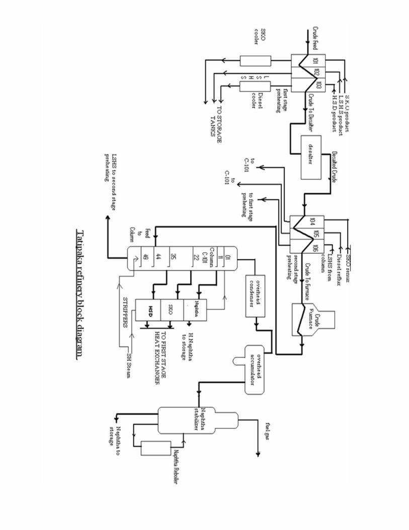
PROCESS DESCRIPTIONCRUDE AND CONDENSATE STORAGE
Crude received from nearby fields is stored in SR1 crude storage tank. Condensate received from Tatipaka GCS and other installations is stored in SR2A and SR2B condensate storage tanks. Crude and condensate are blended in the ratio of 75:25 and fed to the first stage preheating by Crude feed pumps P-101 A/B at a discharge pressure of 10 kg/cm².
FIRST STAGE PREHEATING
Crude is preheated by kerosene heat exchanger, RCO heat exchanger and diesel heat exchanger namely E-101, E-102, E-103 A/B.
In E-101 the heating medium is kerosene product at 165°C which is coming out from kerosene stripper and crude is heated from 35°C up to 72°C.
Similarly, In E-102 the heating medium is RCO at 210°C coming out of E-106 and crude is further heated up to 108°C.
Finally, In E-103 the heating medium is HSD at 240°C coming out of secondary diesel heat exchanger E-105 and crude is further heated up to 135°C.
DESALTER
The desalter is a process vessel that removes salt from the crude by dissolving the salts in the wash water and then removing the brine water (water with dissolved salt) from the crude. Water is added to crude before entering desatler and mixed properly by a mixing valve. As a result, the temperature of crude reduces from 135°C to 125°C.
Desatler operates at temperature of 125°C at a pressure of 14.7 kg/cm² A.
De-emulsifying chemicals are also added at this stage to break down emulsion in crude.
A high emf of 22 KV is applied in the desalter to provide the electrostatic field. which will separate water by gravity.
Part of the salts in crude oil, particularly MgCl, is hydrolysable at temperature of 120°C. Upon hydrolysis, chloride gets converted into HCL which will find its way to distillation columns. This will corrode the overhead condensers. Hence the desalter is essential in the refining operation.
Desalter reduces the salt content of the crude to 0.5ppb max (at the outlet) from 50ppb at the inlet resulting in above 90% removal. The Basic Sediments and Water content (BS&W) is 0.2% w/w.
CRUDE PREHEATING SECOND STAGE
Desalted crude coming from desalter passes through E-104 A/B (crude/kerosene CR heat exchanger) is heated up to 165°C by kerosene circulation reflux from 22nd tray of atmospheric crude column.
After passing through E-104 A/B, Crude passes through crude-diesel CR heat exchanger E-105 A/B where crude is further heated up to 185°C by diesel circulation which is taken from 35th tray of atmospheric crude column.
Then crude is again heated up to 215 °C by hot RCO product coming from atmospheric column bottom in Crude-hot RCO exchanger E-106.
CRUDE FURNACE
The Crude Furnace is a vertical cylindrical Heater with Radiant and Convection sections. It is designed for an absorbed Heat Duty of 1.91MMKcal/ Hr for the Crude service and 0.0046 MM K cal / Hr for Steam Super Heater service. Crude Feed enters the top of the Convection Section at 211 0C. After getting heated with the Flue Gases, passes into Radiant Section where it is further heated up to 350 0C.
Radiant Section has 28 Nos. of 4” dia. Sch. 40, ASTM-A-335 Gr. P5 bare tubes, which are arranged vertically in a single pass, with a total Radiant Heat transfer area of 55.52 m2. There are 12 Nos. of 3” dia., Sch. 40, ASTM-A-335 Gr. P5 bare tubes in 3 rows and 20 Nos. Finned Tubes in 4 rows, 3” dia., Sch. 40, ASTM-A-335 Grade P5. A single row of 11/2 “ dia. Sch. 80, ASTM - a 106, gr. B bare tubes for Steam Super Heating were also provided over the top of the Crude Feed coils.
The furnace is equipped with 3 Low NOX Natural Draft Gas burners with Pilots having ignition facility for heating. Burners are located at the furnace floor. Fuel gas with a heating value of 9200 Kcal/kg enters the burners at a pressure of 0.5 kg/cm² g. An excess 20% of combustion air is taken from the Natural Draft burners. Flue gas at a temperature of 350°C escapes to the atmosphere through furnace stack. Stack is provided with a Damper control, and is actuated manually by winch and cable system from grade level. Furnace Fire Box is provided with Snuffing steam connections for the Radiant Section and Convection Section for snuffing out the combustibles.
Along with crude/condensate mixture feed, de-mineralized water from the boilers in the form of saturated steam is also superheated in the furnace for routing it to the crude column and also the strippers.
ATMOSPHERIC CRUDE COLUMN
The atmospheric crude column is the unit wherein, by heat transfer and mass transfer (distillation) operations, fractionates present in the crude oil are extracted. It is equipped with 49Nos, SS 410 valve type trays and shell internals. Top section is cladded with Monel up to 4th tray.

The column is having an ID of 1067 mm X 34309 mm T/T. It is designed for 4 Kg/cm2 A at 1750C (top section), 350°C (mid section), 400°C (bottom section). The crude column operates at near atmospheric pressure (0.8 kg/cm²) and fractionates the crude oil into Naphtha, Superior Kerosene Oil (kerosene), High Speed Diesel (diesel) and Low Sulphur Heavy Stock products. This column is provided with 49 trays. Partially vaporized crude (15% liquid, 85 % vapour) from the furnace enters the column on tray number 44. The region between 43rd and 44th tray is flashing zone. The significance of flashing zone is that it is the zone (of length 2.5m) wherein the partially vaporized (85% vapor and 15% liquid) crude feed (entering the column at pressure of 2.5kg/cm2) by difference in pressure of column (0.8kg/cm2) separates into vapor and liquid components. The liquid component drops down (as L.S.H.S) 6 trays onto tray #49. The vaporized component moves upward to tray#1. Super heated steam at 6 Kg/cm2is used for the stripping steam. Steam Stripping is done to remove lighter constituents from the Reduced Crude.
The vapors are allowed to move out from the top portion of the column to overhead condensers. Here the vapor gets condensed into light naphtha (containing lighter hydro-carbons i.e. derivatives of propane group and butyl group) and is fully taken back as reflux to the crude column. With the use of naphtha reflux, the subsequent refluxes-diesel (as circulating reflux) are extracted (using centrifugal pump). After the required quantities of refluxes (naphtha, kerosene & diesel) are achieved, the vapors are allowed to exchange heat as well as transfer MASS with the suitable.
Coming to the tray design, the trays used in the column are valve trays (known as Tweetle trays). The upper extended surface of the tray is known as Weir. The lower extended surface of the tray is the Downcomer. The inter tray distance are approximately 0.7m (except flashing zone trays). The trays are so designed that the level of weir of one tray lies higher than that of the preceding trays downcomer, in order to restrict the super heated steam flow through the gap between the weir and downcomer of the tray and the column wall, by creating liquid seal which, otherwise, would hamper the vapor-liquid contact time in the preceding tray thereby reducing the intended heat and mass transfer efficiency and subsequent distillation. The maximum pressure drop per tray is 6 mm of Hg. The design load is 75 of the load corresponding to flooding.
Coming back to the distillation part, after the necessary reflux requirements are met, the distillation process starts, at the respective trays(where reflux enters), by virtue of contact between the vapor and the respective reflux, there occurs heat and mass transfer. The reflux being at lower temperature than the respective vapor, condensation of vapor occurs. The condensed liquid level starts rising on the respective tray and thereby flooding occurs and liquid pours on the trays below.
Nozzles are designed for drawing out the respective products. The nozzles are connected to flow and pressure control valves. After achieving the
requisite liquid quantity (level), the nozzle connected to respective stripper is activated and thereby liquid draw occur (heavy naphtha tray#11, kerosene tray#22 and diesel tray#35). Heavy naphtha tray is maintained at 108-111°C, kerosene draw 178-181°C, diesel draw 265-271°C, bottoms 325-344°C, atmospheric column top 108-111°C.
SIDE STRIPPERS
Stripper columns are used to remove Low boiling point or gaseous components from a liquid stream. The principle of operation is based on Avagadro’s Principle and Dalton’s Law of Partial Pressures. Dalton’s Law states that the pressure exerted by a mixture of gases is equal to the sum of the separate pressures, which each gas would exert if it alone occupied the volume. Avagadro’s Principle states that equal volume of gas at the same condition of temperature and pressure will contain the same number of molecules regardless of type or weight.
This partial pressure effect is used in striping out light hydrocarbons from the side stream of the fractionating columns. Strippers are also used to remove gases like Oxygen, Nitrogen or H2S from liquid streams.The strippers are basically packed towers with structured packing. The side streams Heavy Naphtha, SKO, and HSD taken from the column are fed into the side strippers at the top through a liquid distributor. Superheated steam enters the stripper from the bottom through a vapour distributor. The overhead vapours are taken back to the atmospheric crude column and the bottom products are taken to the product coolers. The maximum pressure drop across the packing is 0.45 inch of H2O per ft. of packing. The tower operates at a load corresponding to 75% flooding.
CIRCULATING REFLUXES
In order to maximize the heat recovery and balance the tower loading, heat is removed by way of circulating refluxes from kerosene and diesel sections. Refluxes (light naphtha reflux at tray#9, kerosene circulating reflux at tray#19 & diesel circulating reflux at tray#32).
OVER HEAD SECTION
The overhead vapor from the crude column at 114°C is withdrawn under pressure control and is condensed and cooled in overhead condenser to 55°C. The condenser utilizes cooling water as the cooling medium. This condensed overhead product separates out as hydrocarbons and water in the overhead accumulator. Water is withdrawn from the boot under level control and sent to the effluent plant for treatment. Naphtha from overhead condensed is pumped to naphtha stabilizer and part to atmospheric column under level cascade control. Crude column top temperature & reflux controller sets reflux demand.
A split range pressure maintains the overhead pressure by controlling fuel gas makeup and vapor to flare.
NAPHTHA STABILISER
The unstabilized naphtha from overhead naphtha accumulator of the crude column is stabilized by the removal of light ends in naphtha stabilizer column. The light ends are recovered as fuel gas and stabilized naphtha at 168°C is obtained from the bottom of column under level control. The necessary heat to vertical reboiler is provided by diesel circulating reflux under temperature control of the naphtha stabilizer bottom. The stabilized naphtha is further cooled in using cooling water and sent to storage tanks.
The stabilizer is provided with a stab-in exchanger to condense the overheated vapor. Water is used as cooling medium and water flow is controlled by column top temperature control. The off gas from the top of column is sent to fuel gas system. Column pressure is controlled by a pressure control provided on fuel gas line.
The stabilizer is a packed tower with structured packing. The top diameter is 305 mm and the bottom diameter is 460 mm with total height of 20.974 m. The total packing volume is 1.59 m³. The maximum pressure drop across the packing is 0.45 inch of H2O per ft. of packing. The tower operates at a load corresponding to 75% flooding.
HEAVY NAPHTHA SECTION
Heavy naphtha is withdrawn as side product from tray#11 of the crude column at a temperature of 144°C under level control of side stripper bottom. Light ends in heavy naphtha steam are stripped in heavy naphtha side-stripper using super heated steam. Stripper vapors routed back to tray#9 of crude column. The bottom product, heavy naphtha pumped by gear pumps and cooled in the heavy naphtha cooler using cooling water. Part of this stream is blended with final diesel product and the rest is mixed stabilized naphtha in naphtha storage tanks.
KEROSENE SECTION
Kerosene is withdrawn as side product from chimney tray, which receives liquid from tray#22 of the crude column at a temperature of 186.7°C under level control of side stripper bottom. Light ends in the kerosene stream are sent back to tray#19 of the crude column. The hot bottom product of kerosene stripper is pumped by gear pump under flow control to crude/ kerosene exchanger. Kerosene product is further cooled in kerosene product cooler to 40°C and is stored in kerosene storage tanks.
DIESEL SECTIONDiesel is withdrawn as side product from tray#35 of crude column at a
temperature of 290°C under level control of side stripper bottom. Lighter ends
are sent back to tray#32 of crude column from diesel stripper. Hot bottom product diesel from stripper is pumped to stage1 preheating of crude followed by cooling the diesel product in cooler and sent to diesel storage tank for storage.LOW SULPHUR HEAVY STOCK SECTION
Stripped RCO at a temperature of 330°C is withdrawn from the bottom of crude column under level control cascaded with flow control. R.C.O is pumped to crude preheat train and the cooled product is sent to storage.
STORAGE TANKS AND LOADING BAY
All the products are cooled to ambient conditions (40°C) before storage, except the bottom product LSHS which gets congealed at lower temperatures. Therefore it is stored in a steam traced and insulated storage tank. The Naphtha product is stored in a floating roof tank while the remaining products are stored in fixed roof tanks. The details of the product storage tanks are given below.Sl. No
Product Stored
TypeCapacity
(m³)Diamete
r (m)Height
(m)Temperatur
e (°C)
1 NaphthaFloating
Roof700 9.95 9.00 40
2 SKO Fixed Roof 443 8.50 7.80 403 HSD Fixed Roof 509 9.00 8.00 404 LSHS Fixed Roof 401 8.25 7.50 95
The products from the storage tanks are pumped to the loading bay for loading into the tankers. Product loading pumps with a pump rate of 60 m³/hr are used for this purpose. These products are loaded into the tankers by loading arms in the loading deck at the loading bay. The loading bay has a fire water sprinkler system for any fire emergency situations.


STEAM GENERATION SYSTEMThe steam generation system consists of a water treatment plant and a
boiler system. The raw water from the raw water reservoir is first treated in treatment plant to remove the impurities and dissolved salts and then fed into the boiler system to produce steam.
Water Treatment Plant
In the water treatment plant, the treatment is done at Primary treatment section and De-Mineralized water plant section.
Primary Treatment Section
Raw water is stored in the raw water reservoir of capacity 1500 m³. In the primary treatment section, raw water is pumped into the lamella clarifier where it is mixed with Alum and flocculent (Magnafloc). The clarified water then enters a multimedia vertical pressure sand filter, which has a capacity of 10 m³/hr and operating at 2.6 kg/cm² where the smaller particles get filtered from the water. This water is then pumped to the DM plant using raw water pumps.
De-Mineralized Water Plant
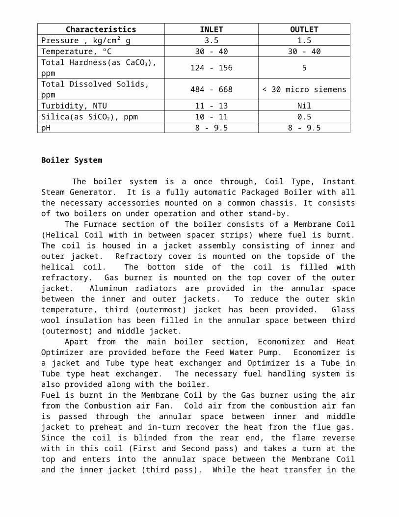
De-Mineralized water plant has a capacity of 2 m³/hr. It consists of a dual media filter, a cation exchanger and an anion exchanger. Water entering the dual media filter undergoes micro filtration to remove micro particles. Dual media filet operates at a pressure of 3.5 kg/cm² g and the filter mediums are LDPE powder and rings. Water then goes through the Ion exchange process in two Ion exchangers namely cation exchanger for the removal of Magnesium, Calcium ions and anion exchanger for the removal of Sulphates, chlorides etc. Both exchangers consists of Ion exchanger resins which should be regenerated with due course of time. Cation exchange resin is regenerated using Hydrochloric Acid and anion exchange resin using Sodium Hydroxide. Regeneration cycle time is approximately 2.45 hours in which 33 litres of HCl (33 %) and 12 kg of NaOH(100%) is used. The inlet and the outlet raw water characteristics are given below.
Characteristics INLET OUTLETPressure , kg/cm² g 3.5 1.5Temperature, ºC 30 - 40 30 - 40Total Hardness(as CaCO3), ppm
124 - 156 5
Total Dissolved Solids, ppm 484 - 668 < 30 micro siemensTurbidity, NTU 11 - 13 NilSilica(as SiCO2), ppm 10 - 11 0.5pH 8 - 9.5 8 - 9.5
Boiler System

The boiler system is a once through, Coil Type, Instant Steam Generator. It is a fully automatic Packaged Boiler with all the necessary accessories mounted on a common chassis. It consists of two boilers on under operation and other stand-by.
The Furnace section of the boiler consists of a Membrane Coil (Helical Coil with in between spacer strips) where fuel is burnt. The coil is housed in a jacket assembly consisting of inner and outer jacket. Refractory cover is mounted on the topside of the helical coil. The bottom side of the coil is filled with refractory. Gas burner is mounted on the top cover of the outer jacket. Aluminum radiators are provided in the annular space between the inner and outer jackets. To reduce the outer skin temperature, third (outermost) jacket has been provided. Glass wool insulation has been filled in the annular space between third (outermost) and middle jacket.
Apart from the main boiler section, Economizer and Heat Optimizer are provided before the Feed Water Pump. Economizer is a jacket and Tube type heat exchanger and Optimizer is a Tube in Tube type heat exchanger. The necessary fuel handling system is also provided along with the boiler.Fuel is burnt in the Membrane Coil by the Gas burner using the air from the Combustion air Fan. Cold air from the combustion air fan is passed through the annular space between inner and middle jacket to preheat and in-turn recover the heat from the flue gas. Since the coil is blinded from the rear end, the flame reverse with in this coil (First and Second pass) and takes a turn at the top and enters into the annular space between the Membrane Coil and the inner jacket (third pass). While the heat transfer in the membrane coil is by radiation, the heat transfer in the third pass is by convection. At the outlet of the boiler, the flue gas is exhausted through the Economizer to recover heat from the flue gases.
Water from the Feed Tank enters the Economizer through the Optimizer before entering the feed water pump. The economizer outlet is again connected to the Optimizer. This water circuit maintains the temperature of the water entering the feed water pump maintained below 80°C, which is the maximum temperature the reciprocating pump can withstand.The steam output from the boiler is 680 kg/hr and the steam pressure is 7.0 kg/cm² at 175°C.
Steam from the boiler is sent to
Crude furnace as snuffing steam and also to produce supersaturated steam for use in Naphtha, Kerosene and Diesel strippers and Crude column bottom.
Desalter Closed Blow down Drum LSHS storage tanks to maintain the temperature of LSHS.
COOLING WATER SYSTEM
Cooling water is used to cool the products and other liquids within the system by taking away the heat. In the refinery, cooling water is mainly used in product coolers E-107 A/B (for HSD), E-108 (for kerosene), E-110 (for heavy naphtha), E-113 (for naphtha), overhead condenser E-109 A/B, stabilizer condenser E-111 and in Closed Blow down Drum. The water from the coolers and condensers are cooled in cooling tower and pumped back using cooling water pumps. Make up water is added for evaporation losses. A number of chemicals like ammonia for pH control, Dispersant, Antiscalant, Biocide to prevent the activities of micro-organisms like bacteria, are added into the cooling water. The list of chemicals added to the cooling water is given below.
Sl. No
Chemical Qty. LevelMix with
Total per day Kgs/Day
Remarks
1 Liquid Ammonia 7%
pH > 7 Water 150 LPD
2 Antiscalant (Maxtreat-2521)
30 Ppm for 4.5 m3/hr
Water 6
3 Dispersant (Maxtreat 7200D)
15 Ppm for 17.5 m3
Water 2
4 Biocide (Maxtreat 606)
100 Ppm for 17.5 m3
Water1(Shock Treating)
Once in 2 weeks
5 Biocide (Maxtreat – 608)
100 Ppm for 17.5 m3
Water1 (Shock Treating)
Once in 2 weeks
Cooling Tower
Cooling tower cools the water coming from product coolers and condensers. There are 2 cooling towers of Induced Draft Cross flow type in the refinery. Tower dimensions are 2.4m x 5.71m x 3.22m. Each has a capacity of 300 m³ of water per hour. The Inlet water temperature is 40°C and after cooling, the outlet is at 30°C. Design heat duty is 2.04 MM Kcal/hr.
CORROSION CONTROL
Corrosion is one of the many environmental factors that can reduce the life of a distillation column. Crude oil contains many corrosive agents; Chlorides, Organic Acids, Water and Sulfur compounds. Chlorides (especially Calcium and Magnesium Chlorides) will hydrolyze above 120°C to form Hydrochloric Acid, HCl. H2S is formed in the heater by thermal decomposition of Sulfur compounds in the crude.
The corrosion attack of Hydrogen Chloride appears in the Overhead system at a point where water begins to condense. The Calcium and Magnesium Chloride content of the crude determine the HCl concentration in the condensed water, the removal efficiency of the desalter, and the quantity of Stripping Steam used. HCl corrosion can affect the Overhead piping,

condensers, the Reflux drum, pump, and water line. The corrosion attack of HCl is accelerated in the presence of Hydrogen Sulfide, H2S.
Close control of the condensate pH is important to minimize the HCl corrosion potential. If pH decreases much below 5.0, system corrosion increases rapidly. Above a pH of 6.0 the amount of H2S that dissociates to H+ and HS- ions increases. A significant concentration of Bisulfide ion in the water phase will also increase system corrosivity.
COOROSION CONTROL CHEMICALS
Filming Amine
An Amine filming corrosion Inhibitor is added to the Overhead line. The amine chemical adheres to the metal walls of the Overhead system to provide a very tenacious film against aqueous corrosion. The Amine chemical is effective over a wide range and is completely soluble in hydrocarbons.Chemical used: COROMAX ML 5872. At the rate of 10 ppm for every 10,000 kg of Overhead vapor.
Neutralizer
An aqueous Ammonium Hydroxide Solution is added separately but in conjunction with the Filming Amine. This Neutralizer reduces acidity by promoting a uniform pH in the condensing steam. The reaction of neutralizer with HCl and H2S acids produces Ammonium Chloride salt that can deposit in the Overhead condenser and cause severe corrosion.
CHEMICAL STORAGE TANKS
In refining operations, many chemicals are involved foe example Corrosion inhibitor, Ammonia as neutraliser, Demuslifier, Acid etc. These chemicals are stored in specific tanks and are pumped into process streams in required amounts. The details of the chemical storage tanks are given below
Sl. No Chemical StoredCapacity
(m³)Temperature
(°C)
1 Corrosion Inhibitor 3.50 40
2 Demulsifier 0.79 40
3 Ammonia Solution 3.50 40
ADDITION OF NEW PRODUCTS
With the in house expertise, two new products were added to the refinery viz. High Flash High Speed Diesel (HF HSD) and Mineral Turpentine Oil (MTO).
HFHSD PRODUCTION
In 2005, with the start of ONGC’s East Coast operations at Kakinada, calls for a huge requirement of HFHSD (HSD with flash point > 66 ºC) for the offshore rigs and supply vessels. Tatipaka refinery until then was producing HSD (FP> 35 ºC) for onshore applications of Rajahmundry and Cauvery Assets. The possibility of producing HSD with a higher flash point of above 66 0C was explored by team refinery.
Design data suggested that the production of HSD with Flash Point > 80 oC was possible with existing column without any modifications. So the operating parameters like steam flow rate, coil outlet temperature from furnace and pump around flow rates of HSD and SKO were calculated and tried. However, the desired specifications for the HF HSD could not be met. The samples were failing either in Flash Point or Pour Point criterion. Upon careful analysis of the lab reports of samples, the poor separation of HSD and SKO cuts was found out to be the root cause for samples failure. Using theoretical calculations and analysis the average cut point temperature for HSD of 275oC was calculated and using the TBP curve of feedstock it was estimated that the yield of HSD would also increase to about 22% for this cut point.
To cope with increased HF HSD production, the exchangers E-107 (HSD cooler) was found to be inadequate to accommodate the additional heat duty. So additional heat exchanger E-107-B, parallel to existing exchanger was designed and installed with due consideration to hydraulic requirements. Further, it was found that the steam flow rates through the strippers and column are regulated manually by isolation valves and the required rate of steam in a controlled manner were not being supplied. So for precise control of superheated steam into strippers, flow control valves in the steam inlet lines were installed and desired steam flow rates could be achieved. Subsequent to these modifications, the HSD samples tested met the specifications of HFHSD. Since then Tatipaka Refinery started supplying HF HSD to offshore rigs.
MINERAL TURPENTINE OIL
The refinery is run by frequent change of feed mix of crude & condensate by monitoring ullage of Naphtha and LSHS Storage Tanks. Also, discounts were offered on Naphtha & LSHS due to marketing problem. Due to this, Refinery margins were affected. There was a drastic change in market dynamics due to supply of Reliance Gas. Hence, the in-house crew of the came up with idea of diversifying the products by converting SKO to Mineral Turpentine Oil (MTO).
The production of SKO of 13-14% can be replaced by MTO to improve refinery profit margins. Mineral Turpentine Oil (MTO) is an intermediate product between Naphtha and SKO. It is a low odor solvent. It has fast setting power and high solvency power. It is widely used in paint and solvent industries, which give it a huge market demand.Applications of MTO
Adhesive industries Paint and resin industries Thinner industries Agro-chemicals, households' insecticides, fungicides industries. Paint catalysts, driers, coating and industries Textiles, cloth, paper, printing-processing industries

Degreasing and cleaning purpose in machineries, machine spares manufacturing industries
Experimentation was done for production of MTO in place of SKO in July, 2010. This was done by process modification in the plant with in house expertise without any Capital expenditure and additional manpower. The operating parameters were modified and feed mix was controlled. Lab tests were successful at M/s ONGC & M/s HPCL and the quality parameters also endorsed by IOGPT. If Need arises, the product MTO can be interchanged with SKO as per market demand without any changes in the plant. This diversification could generate additional revenue of Rs17 Crore per annum after considering the SKO subsidiary and Rs2 Crore with SKO subsidiary. The project obtained the approval of competent authority and MTO production started from 01.4.2011.
The project received CMD innovation group award for the team in 2011.UTILITIES The plant runs on un-interrupted power supplied by gas generators of 380KVA and 500KVA capacity. The fuel gas used here is the low pressure gas generated in GCS which other wise would have been flared, resulting in global warming. The pneumatic control of all the control valves needs air, which is provided by an air compressor. The Effluent generated is treated in the Effluent Treatment Plant located in the adjoining plant of GCS.The power supply to the control system has been provided by uninterrupted power supply (UPS).The product dispatch is done through loading bay. All the activities are recorded in an ERP package called SAP on a daily basis, which can then be viewed across ONGC. The plant is equipped with gas detection and fire detection systems. The MCC room is equipped with smoke detector as well. The plant is equipped with latest fire detection and suppression system which confirms to OISD standards. Different system safety interlocks has been provided in the DCS control system to initiate actions that prevents any damage to plant, equipment and personnel.
LIST OF AWARDS FOR TATIPAKA REFINERY
WON THE GROUP AWARD FROM DIRECTOR (ON-SHORE) FOR SUCCESSFUL COMMISSIONING OF REFINERY IN 2002.GREENTECH ENVIRONMENT EXCELLENCE SILVER AWARD FOR 2003-04

GREENTECH ENVIRONMENT EXCELLENCE SILVER AWARD FOR 2004-05GREENTECH SAFETY SILVER AWARD FOR 2003-04.GREENTECH SAFETY SILVER AWARD FOR 2004-05GREENTECH ENVIRONMENT EXCELLENCE GOLD AWARD FOR 2006.GREENTECH ENVIRONMENT EXCELLENCE GOLD AWARD FOR 2011.CERTIFICATE OF APPRECIATION FROM NATIONAL SAFETY COUNCIL, AP CHAPTER IN RECOGNITION OF THE EFFORTS TOWARDS OHSAS-18001 SERIES in 2005.C&MD INNOVATION GROUP AWARD IN 2011 FOR TEAM REFINERY FOR INTRODUCTION OF NEW PRODUCT MTO.WON THE HIGH TECHNICAL AUDIT RATED AWARD FROM DIRECTOR (T&FS) DURING THE YEAR IN 2008-09