refractory installation quality control ballot inspection...
TRANSCRIPT
This document is under review as revision to an API Standard; it is under consideration within an API technical committee but has not received all approvals required for publication. This document shall not be reproduced or circulated or quoted, in whole or in part, outside of API committee activities except with the approval of the Chairman of the committee having jurisdiction and staff of the API Standards Dept. Copyright API. All rights reserved.
1
Refractory Installation Quality Control—Inspection and Testing AES/RCF Fiber Linings and Materials
API STANDARD 976 Proposed FIRST EDITION Ballot Draft
NW: Copy the SCI for comments.
BALLOT DRAFT. FOR REVIEW AND COMMENT ONLY.
This document is under review as revision to an API Standard; it is under consideration within an API technical committee but has not received all approvals required for publication. This document shall not be reproduced or circulated or quoted, in whole or in part, outside of API committee activities except with the approval of the Chairman of the committee having jurisdiction and staff of the API Standards Dept. Copyright API. All rights reserved.
2
Important Information Concerning Use of Asbestos or Alternative Materials Asbestos is specified or referenced for certain components of the equipment described in some API standards. It
has been of extreme usefulness in minimizing fire hazards associated with petroleum processing. It has also been
a universal sealing material, compatible with most refining fluid services.
Certain serious adverse health effects are associated with asbestos, among them the serious and often fatal
diseases of lung cancer, asbestosis, and mesothelioma (a cancer of the chest and abdominal linings). The degree
of exposure to asbestos varies with the product and the work practices involved.
Consult the most recent edition of the Occupational Safety and Health Administration (OSHA), U.S. Department of
Labor, Occupational Safety and Health Standard for Asbestos, Tremolite, Anthophyllite, and Actinolite, 29 Code of
Federal Regulations Section 1910.1001; the U.S. Environmental Protection Agency, National Emission Standard for
Asbestos, 40 Code of Federal Regulations Sections 61.140 through 61.156; and the U.S. Environmental Protection
Agency (EPA) rule on labeling requirements and phased banning of asbestos products (Sections 763.160-179).
There are currently in use and under development a number of substitute materials to replace asbestos in certain
applications. Manufacturers and users are encouraged to develop and use effective substitute materials that can
meet the specifications for, and operating requirements of, the equipment to which they would apply.
SAFETY AND HEALTH INFORMATION WITH RESPECT TO PARTICULAR PRODUCTS OR MATERIALS CAN
BE OBTAINED FROM THE EMPLOYER, THE MANUFACTURER OR SUPPLIER OF THAT PRODUCT OR
MATERIAL, OR THE MATERIAL SAFETY DATASHEET.
BALLOT DRAFT. FOR REVIEW AND COMMENT ONLY.
This document is under review as revision to an API Standard; it is under consideration within an API technical committee but has not received all approvals required for publication. This document shall not be reproduced or circulated or quoted, in whole or in part, outside of API committee activities except with the approval of the Chairman of the committee having jurisdiction and staff of the API Standards Dept. Copyright API. All rights reserved.
3
Table of Contents
API Staff NOTE: Page numbers will be included in the final page proof.
1 Scope
2 Normative References
3 Terms and Definitions
4 Responsibilities
4.1 Owner/EM
4.2 Installer
4.3 Inspector
4.4 Refractory Manufacturer
5 Inspector Qualifications
6 Materials
6.1 Physical Property Requirements
6.2 Shipping and Storage
6.3 Packaging
6.4 Marking
6.5 Weather Protection
6.6 Shelf Life
6.7 Discarding Criteria
7 Lining Design
8 Rigidized and Surface Treated Fiber
9 Refractory QA/QC, Examination and Testing
10 Preparation for Shipment
11 Packaging/Storage/Shelf Life
11.1 Anchor Inspection and Testing
11.2 Fiber Lining Inspection and Testing
11.3 Installation workmanship for fiber linings
BALLOT DRAFT. FOR REVIEW AND COMMENT ONLY.

This document is under review as revision to an API Standard; it is under consideration within an API technical committee but has not received all approvals required for publication. This document shall not be reproduced or circulated or quoted, in whole or in part, outside of API committee activities except with the approval of the Chairman of the committee having jurisdiction and staff of the API Standards Dept. Copyright API. All rights reserved.
4
Contents (continued)
Annex A (normative) Refractory Compliance Datasheet
Annex B (informative) Suggested Minimum Inspector Competencies
Figures
Figure 7.1—Typical Stud Layout for Overlap Blanket Systems Figure 7.2—Typical Layered Fiber Lining Anchoring Systems Figure 7.3—Examples of Modular Fiber Systems Figure 7.4—Hardware Span Required for Overhead Section Modules Figure 7.5—Typical Module Orientations Figure 7.6—Typical Blanket Lining Repair of Hot-Face Layer Figure 7.7—Typical Blanket Lining Repair of Multiple Layers Figure 7.8—Typical Repair of Modular Fiber Linings Figure 7.9—Typical Repair of Modular Fiber Linings Figure A.1—Manufacturer’s Product Compliance Data Sheet: Fiber Materials
Tables
Table 6.1—Documentation Required for Fiber per ASTM C892 Table 6.2—Maximum Temperature of Anchor Tips Table 9.1—Minimum Hammer/Bend Test Frequency Table A.1—Test Methods to Determine RCF/AES Properties Table B.1—Suggested Minimum Inspector Competencies
BALLOT DRAFT. FOR REVIEW AND COMMENT ONLY.

This document is under review as revision to an API Standard; it is under consideration within an API technical committee but has not received all approvals required for publication. This document shall not be reproduced or circulated or quoted, in whole or in part, outside of API committee activities except with the approval of the Chairman of the committee having jurisdiction and staff of the API Standards Dept. Copyright API. All rights reserved.
API 976
5
Refractory Installation Quality Control—Inspection and Testing AES/RCF Fiber Linings
1 Scope
This standard provides installation quality control procedures for AES/RCF fiber linings and may be used to supplement owner specifications. Materials, equipment, and personnel are qualified by the methods described, and applied refractory quality is closely monitored, based on defined procedures and acceptance criteria. The responsibilities of inspection personnel who monitor and direct the quality control process are also defined.
2 Normative References
The following referenced documents are indispensable for the application of this document. For dated references, only the edition cited applies. For undated references, the latest edition of the referenced document (including any amendments) applies.
API Standard 560, Fired Heaters for General Refinery Service
API Standard 936, Refractory Installation Quality Control – Inspection and Testing of Monolithics
ASTM C177 1 , Standard Test Method for Steady-State Heat Flux Measurements and Thermal Transmission Properties by Means of the Guarded-Hot-Plate Apparatus ASTM E1172: Standard Practice for Describing and Specifying a Wavelength-Dispersive X-Ray Spectrometer
ASTM C201, Standard Test Method for Thermal Conductivity of Refractories
ASTM C612, Standard Specification for Mineral Fiber Block and Board Thermal Insulation
ASTM C892, Standard Specification for High-Temperature Fiber Blanket Thermal Insulation
ASTM C1113, Standard Test Method for Thermal Conductivity of Refractories by Hot Wire (Platinum Resistance Thermometer Technique)
ASTM C892-10, Standard Specification for High-Temperature Fiber Blanket Thermal Insulation
SSPC-SP 32, Power Tool Cleaning
SSPC-SP 7/NACE No. 4, Brush-Off Blast Cleaning
1 ASTM International, 100 Barr Harbor Drive, West Conshohocken, Pennsylvania 19428, www.astm.org
2 The Society for Protective Coatings, 40 24th Street, 6th Floor, Pittsburgh, Pennsylvania 15222, www.sspc.org.
BALLOT DRAFT. FOR REVIEW AND COMMENT ONLY.
This document is under review as revision to an API Standard; it is under consideration within an API technical committee but has not received all approvals required for publication. This document shall not be reproduced or circulated or quoted, in whole or in part, outside of API committee activities except with the approval of the Chairman of the committee having jurisdiction and staff of the API Standards Dept. Copyright API. All rights reserved.
API 976
6
3 Terms and Definitions For the purposes of this document, the following definitions apply.
3.1 alkaline earth silicate fiber AES Manmade vitreous fiber (MMVF) composed of at least 18% alkali earth oxides developed to meet the fiber exemption requirements spelled out in 97/69/EC of the Dangerous Substances Initiative in the European Union EU. These fibers are exonerated from the EU carcinogen classification on the basis of their low bio-persistence. They also may be known as bio-fiber, bio-soluble or low bio-persistence fiber.
3.2 anchor Metallic or refractory device that holds the refractory or insulation in place.
3.3
ash3 The noncombustible residue that remains after burning a fuel or other combustible material. This residue is considered to be a foulant that can foul the exterior of heater tubes.
NOTE Ash may be corrosive to steel or the refractory lining, depending on the composition and metals content of the fuel.
3.4 batten strip A single or folded layer of fiber blanket placed and compressed between courses of fiber modules.
3.5 bull nose4 A rounded convex edge, corner, or projection such as at the flue gas inlet to a convection section.
3.6 casing3 Metal plate used to enclose the fired heater.
3.7 ceramic fiber Fibrous refractory insulation that can be in the form of refractory ceramic fiber or manmade vitreous fiber (MMVF).
NOTE Applicable forms include bulk, blanket, board, modules, paper, coatings, pumpables, cements, moldables, and vacuum-formed shapes.
3.8
classification temperature The temperature at which the product has a linear shrinkage not exceeding 4% (for blanket, paper) and 2% (for vacuum form, boards) after 24-hour heat treatment and in a neutral atmosphere.
NOTE In the field, the continuous application temperature is typically 100 °C to 150 °C (210 °F to 302 °F) below the classification temperature. Above that temperature, crystallization can occur and shrinkage increases. Polycrystalline PCW fiber can generally be used at up to classification temperature.
3 American Concrete Institute, 38800 Country Club Drive, Farmington Hills, Michigan 48332, www.aci-int.org.
4 API 560
BALLOT DRAFT. FOR REVIEW AND COMMENT ONLY.
This document is under review as revision to an API Standard; it is under consideration within an API technical committee but has not received all approvals required for publication. This document shall not be reproduced or circulated or quoted, in whole or in part, outside of API committee activities except with the approval of the Chairman of the committee having jurisdiction and staff of the API Standards Dept. Copyright API. All rights reserved.
API 976
7
Fiber materials are available in three grades (classification temperature):
— Alkaline Earth Silicate (AES) Fiber up to 1200 °C (2192 °F),
— Refractory Ceramic (RCF) Fiber up to 1300 °C (2372 °F),
— Polycrystalline (PCW) Fiber > 1300 °C (2372 °F).
3.9 cold-face3 The surface of a refractory lining against the metal casing surface.
3.10
compliance datasheet5 A list of mechanical and chemical properties for a specified refractory material that are warranted by the manufacturer to be met if and when the product is tested by the listed procedure.
3.11 construction joint A joint formed in a lining to mechanically decouple refractory components without expansion allowance.
3.12 design temperature (refractory) The maximum continuous use temperature of the hot face or interface, plus a design margin of 165 °C (300 °F). NOTE The refractory design temperature is used to select refractory material.
3.13 dual layer3 Refractory construction comprised of two refractory materials wherein each material performs a separate function (e.g., a dense monolithic over insulating monolithic.
3.14 EM Original Equipment Manufacturer or Equipment Supplier with overall responsibility for design, fabrication, and delivery of a finished product.
3.15 expansion joint3 A non-bonded joint in a lining system with a gap designed to accommodate thermal expansion of adjoining materials, commonly packed with a temperature resistant compressible material such as fiber.
3.16 fabricator (refractory installation) Company responsible for the overall fabrication of the fired equipment in which refractory is installed.
3.17 fiber component fabricator A third party separate from the refractory manufacturer and the installation contractor engaged in a business of purchasing fiber and anchor materials that are fabricated into modular lining components. These components are then purchased and installed by the installation contractor.
5 API 936
BALLOT DRAFT. FOR REVIEW AND COMMENT ONLY.
This document is under review as revision to an API Standard; it is under consideration within an API technical committee but has not received all approvals required for publication. This document shall not be reproduced or circulated or quoted, in whole or in part, outside of API committee activities except with the approval of the Chairman of the committee having jurisdiction and staff of the API Standards Dept. Copyright API. All rights reserved.
API 976
8
3.18 form3 1. Shaped—Sold as finished units, installed as building blocks.
2. Monolithic (Unshaped)—Final shape formed upon application.
3. MMVF/AES/RCF Fiber.
3.19 fuels fired3 The type of fuels fired in the heater. Corrosive ash and impurities in the fuel (e.g. sulfur, alkali and heavy metals) will guide selection of the type or form of refractory and the method of construction for refractory linings.
3.20 header box3 Internally insulated compartment, separated from the flue gas stream, which is used to enclose a number of headers or manifolds.
NOTE Access is afforded by means of hinged doors or removable panels.
3.21 high-temperature insulation fiber An accumulation of fibers of different lengths and diameters, produced synthetically from mineral raw materials. This group of fibers includes alkaline earth silicate (AES) and aluminum-silicate as well as polycrystalline (PCW) with a classification temperatures >1000 °C (1830 °F).
3.22 hot-face layer3 Refractory layer exposed to the highest temperatures in a multilayer or multicomponent lining.
3.23 hot-face temperature3 Temperature of the refractory surface in contact with the flue gas or heated combustion air. This is the temperature used for thermal calculations for operating cold-face temperature and heat loss.
3.24 Installer3 Company or individual responsible for installing the refractory lining.
3.25 interface temperature3 Calculated temperature between any two adjacent layers of a multi-layer or multicomponent refractory construction.
3.26 low bio-persistence3 Materials having solubility in body fluids and designed to be cleared from the lungs very quickly if they are inhaled. Clearance occurs through the body’s natural defense mechanisms.
3.27 manmade vitreous fiber MMVF A class of insulating materials made primarily from glass, rock, slag or clay. The four general categories included as MMVF are fiberglass, mineral wool, alkaline earth silicate fiber and refractory ceramic fiber.
NOTE MMVF is also referred to as synthetic vitreous fibers (SVF).
BALLOT DRAFT. FOR REVIEW AND COMMENT ONLY.
This document is under review as revision to an API Standard; it is under consideration within an API technical committee but has not received all approvals required for publication. This document shall not be reproduced or circulated or quoted, in whole or in part, outside of API committee activities except with the approval of the Chairman of the committee having jurisdiction and staff of the API Standards Dept. Copyright API. All rights reserved.
API 976
9
3.28 maximum continuous use temperature3 Maximum temperature to which a refractory may be continuously exposed without excessive shrinkage or mechanical breakdown. It is also sometimes referred to as the “recommended use limit” or “continuous-use temperature.”
NOTE This may not be the same as the “Maximum Service Temperature” quoted on the manufacturer’s product data sheet.
3.29 Module3 Construction of fibrous refractory insulation in stacked/folded blankets or monolithic form, commonly with an integrated attachment system.
3.30 Mineral Wool Block Block insulation composed of mineral wool fiber and an organic binder.
3.31 multicomponent lining3 Refractory system consisting of two or more layers of different refractory types.
NOTE Examples of refractory types are castable, insulating firebrick, firebrick, block, board, and ceramic fiber.
3.32 multilayer lining3 Refractory system consisting of two or more layers of the same refractory type.
3.33 needled3
A knitted structure of fibers to enhance handling and mechanical strength.
3.34 Owner The proprietor of the lined equipment who has engaged one or more parties to install or repair refractory.
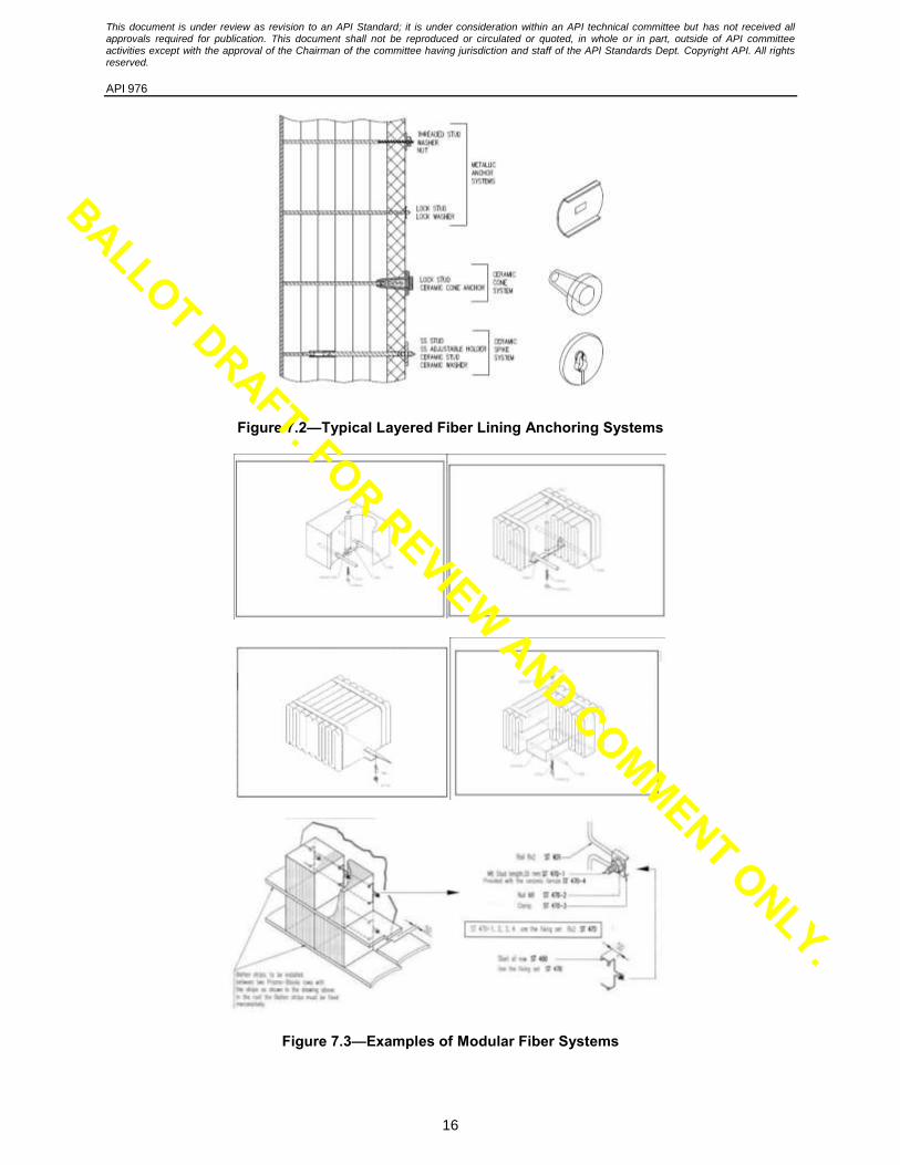
3.35 Parquet A module lining design where module support anchoring is aligned perpendicular for each adjacent module (see Figure 7.3).
3.36 permanent linear change4 A measure of a refractory’s physical property that defines the change in dimensions as a result of initial heating to a specific temperature.
3.37 Polycrystalline (PCW) Fiber Fibers containing greater than 70% Al2O3 that are produced by a “sol-gel method” from aqueous spinning solutions. Generally used at application temperatures greater than 1300 °C (2370 °F) and in critical chemical and physical application conditions.
3.38 protective coating3 Corrosion-resistant material applied to a metal surface.
EXAMPLE Coating on casing plates behind porous refractory materials to protect against sulfur in the flue gases.
BALLOT DRAFT. FOR REVIEW AND COMMENT ONLY.
This document is under review as revision to an API Standard; it is under consideration within an API technical committee but has not received all approvals required for publication. This document shall not be reproduced or circulated or quoted, in whole or in part, outside of API committee activities except with the approval of the Chairman of the committee having jurisdiction and staff of the API Standards Dept. Copyright API. All rights reserved.
API 976
10
3.39 qualification test3 Pre-installation evaluation of materials and/or applicators to verify that materials purchased and equipment/personnel that will be installing the refractory material/s are capable of meeting specified quality standards.
3.40 refractory ceramic fibers3 RCF MMVF whose chemical constituents are predominantly alumina and silica.
3.41 rigidizer3 A liquid applied to AES/RCF which produces a rigid lining surface when dried.
3.42 Shot Un-fiberized, more spherical shaped material in AES fibers that does not contribute the insulating capability of fibrous insulation. Fine shot size distribution is not acceptable.
Soldier course A module lining design where module support anchoring is aligned (parallel) similarly for all modules in a row (see Figure 7.5).
3.43 sprayable/pumpable fibers3 Mixture of bulk fiber and wet binder suitable for pumping or spraying.
3.44 staples Anchor hooks to secure the batten strip to the module (mandatory in arches)
3.45 temperature allowance3 Number of degrees Fahrenheit (Celsius) to be added to the process fluid temperature to account for flow maldistribution and operating unknowns.
NOTE The temperature allowance is added to the calculated maximum tube-metal temperature or the equivalent tube-metal temperature to obtain the design metal temperature.
3.46 thermal resistance3 Ability of an insulation to resist heat flow from the hot-face to the cold face. A wide range of thermal resistances are possible by the selection of refractories with different thermal conductivities and/or lining thicknesses.
3.47 tie-backs3 Mechanical fastening devices used to hold a refractory lining structure in position while permitting the lining to thermally expand and contract.
3.48 vacuum formed3 A manufacturing process combining fibers and binder components and using vacuum to form a rigid, densified shape when dried.
3.49 vapor barrier3 Metallic foil placed between layers of refractory as a barrier to flue gas flow. This barrier protects the steel shell from corrosion of condensing acids.
BALLOT DRAFT. FOR REVIEW AND COMMENT ONLY.
This document is under review as revision to an API Standard; it is under consideration within an API technical committee but has not received all approvals required for publication. This document shall not be reproduced or circulated or quoted, in whole or in part, outside of API committee activities except with the approval of the Chairman of the committee having jurisdiction and staff of the API Standards Dept. Copyright API. All rights reserved.
API 976
11
3.50 wet blanket3 (refractory) Flexible, formable, RCF blanket saturated with wet binder that sets on heat exposure forming a rigid durable structure.
4 Responsibilities 4.1 Owner/EM
4.1.1 The Owner/EM shall provide a detailed specification based on manufacturer design technology. The specification shall include the following design details.
a) Lining products, construction, thickness, method of application, and extent of coverage.
b) Anchor materials, geometry, layout and weld details.
c) EM shall provide a plan for stiffening and protecting installed linings during handling and transport of pre-lined components subject to the Owner’s approval.
4.1.2 The Owner/EM shall approve the engineering drawings and project execution plan prior to any installation activity. The engineering design is unique for each manufacturer.
4.1.3 The Owner/EM shall provide an inspector(s) for the refractory installation work who has minimum competencies that are appropriate for the required work scope.
NOTE Annex B lists suggested refractory inspector minimum competencies.
4.1.4 The Owner/EM shall resolve the following:
a) Exceptions, substitutions, and deviations to the requirements of any execution plan, this standard, and other referenced documents.
b) Work deficiencies discovered and submitted by the inspector.
4.2 Installer
4.2.1 The installer shall prepare a detailed execution plan in accordance with this standard and the requirements of the Owner/EM specification and quality standard. The execution plan shall be submitted for the Owner/EM approval, and agreed to in full before work starts. Execution details shall include:
a) Designation of responsible parties.
b) Designation of inspection hold points and the required advance notification to be given to the inspector.
c) Surface preparation, anchor layout and welding procedures.
d) Procedures for material storage, installation and quality control
e) Provisions for evaluating fiber damage due to wetting before or after installation.
f) Field records documenting design/procedures with the actual layout drawing shown in the execution plan.
4.2.2 The installer shall set demonstrate (mock-up) step by step procedures for installing the fiber lining components.
4.2.3 Submission clearly identifying to the Owner/EM all exceptions, substitutions, and deviations to the requirements of the execution plan, this standard and other referenced documents. Owner/EM approval shall be secured before implementation of the changes.
4.2.4 Scheduling and execution of work to qualify all equipment and personnel required to complete installation work, including documentation and verification by the inspector.
4.2.5 Advance notification to the Owner/EM of all times and locations where work will take place so that this information can be passed on to the inspector.
4.2.6 Execution of installation work.
BALLOT DRAFT. FOR REVIEW AND COMMENT ONLY.
This document is under review as revision to an API Standard; it is under consideration within an API technical committee but has not received all approvals required for publication. This document shall not be reproduced or circulated or quoted, in whole or in part, outside of API committee activities except with the approval of the Chairman of the committee having jurisdiction and staff of the API Standards Dept. Copyright API. All rights reserved.
API 976
12
4.2.7 Provide inspector verified documentation of installation records, including:
a) Product(s) being applied.
b) Pallet code numbers and location where applied.
c) Installation crew members.
d) Weather conditions and any other unusual conditions or occurrences.
4.2.8 Accountability for installed refractories meeting specified standards.
4.3 Inspector
4.3.1 Monitor production work to ensure compliance with job specifications and agreed-to quality practices.
4.3.2 Notify the Owner/EM and the contractor of any work deficiencies. Notification shall be made according to the job specific requirements outlined in the procedures. Notification shall take place as soon as possible, and shall occur within one working day after the discovery of the deficiency. Notify the Owner/EM in writing.
4.3.3 Verify style, layout and composition of anchors are installed in accordance with the project requirements
4.3.4 Make no engineering decisions unless approved by Owner/EM. Conflicts between the specified execution plan and the actual installation procedures shall be submitted to the Owner/EM for resolution.
4.3.5 Inspect and test anchors, dimensions, layout and welds.
4.3.6 Check and verify that accurate installation records are being documented by the contractor.
4.4 Refractory Manufacturer
4.4.1 Provide compliance data sheets to the purchaser upon request.
4.4.2 Provide material(s) that meets the approved compliance datasheet.
4.4.3 The manufacturer shall provide recommended guidelines for weather protection and storage of products.
4.5 Component Fabricator
The component fabricator shall provide details of component construction to the Owner/EM.
5 Inspector Qualifications 5.1 The inspector shall have no commercial affiliations with the contractor or manufacturer(s).
5.2 The inspector(s) monitoring the refractory installation work shall have minimum competencies that are appropriate for the required work scope.
NOTE Annex B lists suggested refractory inspector minimum competencies.
5.3 The inspector shall possess this standard, owner specifications, the project execution plan, the inspection and test plan, and other job-specific requirements outlined by the owner, contractor, and/or manufacturer. The inspector shall have working knowledge of these documents.
6 Materials 6.1 Physical Property Requirements 6.1.1 Refractory
Refractory materials shall be selected based on physical properties specified by the purchaser as defined in Table 6.1.
BALLOT DRAFT. FOR REVIEW AND COMMENT ONLY.
This document is under review as revision to an API Standard; it is under consideration within an API technical committee but has not received all approvals required for publication. This document shall not be reproduced or circulated or quoted, in whole or in part, outside of API committee activities except with the approval of the Chairman of the committee having jurisdiction and staff of the API Standards Dept. Copyright API. All rights reserved.
API 976
13
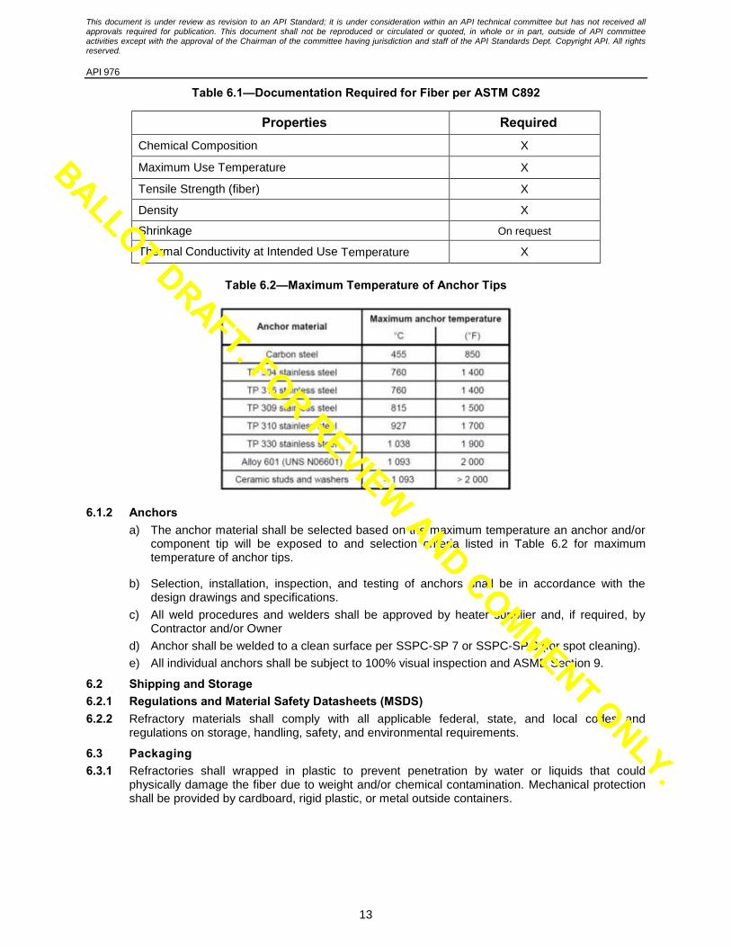
Table 6.1—Documentation Required for Fiber per ASTM C892
Properties Required Chemical Composition X
Maximum Use Temperature X
Tensile Strength (fiber) X
Density X
Shrinkage On request
Thermal Conductivity at Intended Use Temperature X
Table 6.2—Maximum Temperature of Anchor Tips
6.1.2 Anchors a) The anchor material shall be selected based on the maximum temperature an anchor and/or
component tip will be exposed to and selection criteria listed in Table 6.2 for maximum temperature of anchor tips.
b) Selection, installation, inspection, and testing of anchors shall be in accordance with the design drawings and specifications.
c) All weld procedures and welders shall be approved by heater supplier and, if required, by Contractor and/or Owner
d) Anchor shall be welded to a clean surface per SSPC-SP 7 or SSPC-SP 3 (for spot cleaning).
e) All individual anchors shall be subject to 100% visual inspection and ASME Section 9.
6.2 Shipping and Storage 6.2.1 Regulations and Material Safety Datasheets (MSDS) 6.2.2 Refractory materials shall comply with all applicable federal, state, and local codes and
regulations on storage, handling, safety, and environmental requirements.
6.3 Packaging 6.3.1 Refractories shall wrapped in plastic to prevent penetration by water or liquids that could
physically damage the fiber due to weight and/or chemical contamination. Mechanical protection shall be provided by cardboard, rigid plastic, or metal outside containers.
BALLOT DRAFT. FOR REVIEW AND COMMENT ONLY.
This document is under review as revision to an API Standard; it is under consideration within an API technical committee but has not received all approvals required for publication. This document shall not be reproduced or circulated or quoted, in whole or in part, outside of API committee activities except with the approval of the Chairman of the committee having jurisdiction and staff of the API Standards Dept. Copyright API. All rights reserved.
API 976
14
6.3.2 Each alloy anchor shall be stamped or laser etched or supplied in sealed traceable packaging to identify alloy and forming manufacturer. Anchors from open packaging not stamped/etched or being installed from a freshly opened package shall be confirmed by 100% PMI before installation.
6.3.3 The classification of all welding consumables shall be identified on the package and/or spool or welding rod.
6.4 Marking 6.4.1 Refractory bags or containers shall be marked with the product name, batch number, hazards
identification label, and date of manufacture.
6.4.2 Packages or containers shall be marked with form, density and temperature rating of the fiber product contained within.
6.4.3 Packaging for anchors shall be marked for alloy composition and the physical dimensions of the anchors contained.
6.4.4 At least one visible surface of blanket, board or module of 1425 °C (2600 °F) grade fiber shall be marked to differentiate it from standard 1260 °C (2300 °F) grade fiber products.
6.5 Weather Protection Refractory materials shall be stored in a weather protected area. The storage facility shall prevent moisture contact with the refractory. Storage shall be on an elevated, ventilated platform. Moisture shall be directed away from the refractory.
6.6 Shelf Life The fiber manufacturer’s shelf life restrictions shall apply.
6.7 Discarding Criteria Packages of refractory with broken seals or that have become damp or wet shall be subject to discard. The concerned manufacturer shall be involved to assess and gauge the usability of the material for reevaluation after expiry of shelf life.
7 Lining Design 7.1 Ceramic fiber shall not be used as the hot face layer if the design hot-face temperature exceeds
700 °C (1300 °F) when the fuel’s combined sodium and vanadium content exceed 100 parts per million (weight basis) in the fuel being fired.
7.2 In layered construction, hot-face layer shall be needled blanket with a 25 mm (1 in.) thickness and 128 kg/m
3 (8 lb/ft
3) density. Fiberboard, if applied as a hot-face layer, shall not be less than 38
mm (1.5 in.) thick, nor have a density less than 240 kg/m3 (15 lb/ft
3). Backup layer(s) of fiber
blanket shall be needled material with a minimum density of 96 kg/m3 (6 lb/ft
3). Blanket shall have
a maximum width of 600 mm (24 in.) and be applied using an approved anchoring system.
7.3 Maximum dimensions for fiberboard used on the hot-face shall be:
a) 600 mm x 600 mm (24 in. x 24 in.), maximum, if the design hot-face temperature is below 1100 °C (2000 °F) on sidewalls.
b) 450 mm x 450 mm (18 in. x 18 in.), maximum, if the design hot-face temperature exceeds 1100 °C (2000 °F), or if used on the roof at any temperature.
7.4 The hot face blanket layer shall be overlap design [typically 100 mm (4 in.)], as shown in Figure 7.1, and shall only use a fiber blanket size of 610 mm (24 in.) wide x 25 mm (1 in.) thick]. Anchor retaining clips (Figure 7.2) shall be installed with 12 mm to 25 mm (½ in. to 1 in.) compression.
7.5 Back-up blanket layers shall be butt joint design.
7.6 Anchor spacing shall be as follows:
a) Vertical Walls—Spacing across the blanket width shall be on 254 mm (10 in.) centers. Spacing along the blanket length shall be 254 mm to 305 mm (10 in. to 12 in.). In more
BALLOT DRAFT. FOR REVIEW AND COMMENT ONLY.

This document is under review as revision to an API Standard; it is under consideration within an API technical committee but has not received all approvals required for publication. This document shall not be reproduced or circulated or quoted, in whole or in part, outside of API committee activities except with the approval of the Chairman of the committee having jurisdiction and staff of the API Standards Dept. Copyright API. All rights reserved.
API 976
15
extreme conditions (vibration or other), tighter centers of less than 254 mm (10 in.) are acceptable and advisable.
b) Overhead (arch, hip roof, etc.)—Spacing across the blanket width shall be on 254 mm (10 in.) centers. Spacing along the blanket length shall be 225 mm to 250 mm (9 in. to 10 in.). In more extreme conditions (vibration or other), tighter centers of less than 225 mm (9 in.) are acceptable and advisable.
7.7 Fiber blanket shall not be used as the hot-face layer when gas velocities are in excess of 12 m/s (40 ft/s). Wet blanket, fiberboard, or modules shall not be used as hot-face layers when velocities are greater than 30 m/s (100 ft/s).
7.8 Fiber blanket shall be installed with its longest dimension in the direction of gas flow. The hot-face layer of blanket shall be constructed with all joints overlapped. Overlaps shall be in the direction of gas flow. Hot-face layers of fiberboard shall be constructed with tight butt joints.
7.9 Fiber blanket used in backup layers shall be installed with butt joints with at least 13 mm (½ in.) compression on the joints. All joints in successive layers of blanket shall be staggered.
7.10 Module systems (Figure 7.3) shall be installed so that joints at each edge are compressed to avoid gaps due to shrinkage.
Figure 7.1—Typical Stud Layout for Overlap Blanket Systems
BALLOT DRAFT. FOR REVIEW AND COMMENT ONLY.
This document is under review as revision to an API Standard; it is under consideration within an API technical committee but has not received all approvals required for publication. This document shall not be reproduced or circulated or quoted, in whole or in part, outside of API committee activities except with the approval of the Chairman of the committee having jurisdiction and staff of the API Standards Dept. Copyright API. All rights reserved.
API 976
16
Figure 7.2—Typical Layered Fiber Lining Anchoring Systems
Figure 7.3—Examples of Modular Fiber Systems
BALLOT DRAFT. FOR REVIEW AND COMMENT ONLY.

This document is under review as revision to an API Standard; it is under consideration within an API technical committee but has not received all approvals required for publication. This document shall not be reproduced or circulated or quoted, in whole or in part, outside of API committee activities except with the approval of the Chairman of the committee having jurisdiction and staff of the API Standards Dept. Copyright API. All rights reserved.
API 976
17
7.11 Modules shall be designed so that support hardware spans over at least 80% of the module width (Figure 7.4).
7.12 Modules shall be installed in soldier-course with batten strips. A parquet pattern is only acceptable on flat arches and typically does not require batten strips. See Figure 7.5 for an example of each. Figure 7.6 shows a typical batten strip design showing offset cut through the lining thickness and possible max length.
7.13 Anchors shall be attached to the casing before modules are installed.
7.14 Internal hardware and anchors shall comply with the maximum tip temperature defined for studs in Table 6.2 based on the highest calculated temperature for each of the components.
7.15 Full thickness fiber linings shall not be used for the lining of floors where maintenance traffic and scaffolding construction are anticipated.
7.16 Fiber shall not be used in convection sections where soot blowers, steam lances or water wash facilities are used.
7.17 Anchors shall be installed before applying protective coatings to the casing. The coating shall cover the attachment studs and anchors so that uncoated parts are above the acid dew-point temperature.
7.18 For fuels having a sulfur content exceeding 200 mg/kg (200 ppm by mass), the casing and carbon steel anchor components that will be operating below acid dew-point temperature shall be coated to prevent corrosion. The protective coating shall have a maximum continuous use temperature of 175 °C (350 °F) or greater and it shall be applied after the anchors are welded to the casing.
7.19 For fuels having a sulfur content exceeding 500 mg/kg (500 ppm by mass), a 2 mil (50 micron) vapor barrier of austenitic stainless steel foil shall be provided in addition to coating. The vapor barrier shall be installed in soldier course and located so that the exposed temperature is at least 55 °C (100 °F) above the calculated acid dew point for all operating cases. Vapor barrier edges shall be overlapped by at least 175 mm (7 in.). Edges and punctures shall be overlapped and sealed with sodium silicate or colloidal silica.
7.20 Mineral wool block shall not be used against the casing.
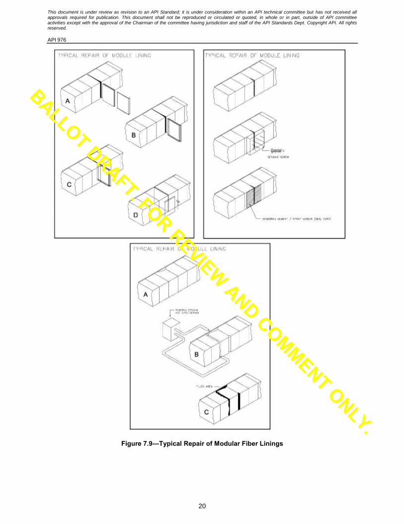
7.21 Typical patch repairs [e.g. less than 0.465 m2 (5 ft
2)] are shown in Figure 7.7 and Figure 7.8 for
blanket lining systems and Figure 7.9 for a modular system.
Staple
staple installation
Figure 7.4—Hardware Span Required for Overhead Section Modules and Typical Staples to Secure Batten Strip to Module in Overhead Installations
BALLOT DRAFT. FOR REVIEW AND COMMENT ONLY.

This document is under review as revision to an API Standard; it is under consideration within an API technical committee but has not received all approvals required for publication. This document shall not be reproduced or circulated or quoted, in whole or in part, outside of API committee activities except with the approval of the Chairman of the committee having jurisdiction and staff of the API Standards Dept. Copyright API. All rights reserved.
API 976
18
Figure 7.5—Typical Module Orientations
Figure 6: Typical joint details for single batten strips.
1" Compressed to ½”
Shiplap JointZ Joint
3"
Figure 7.6—Typical Joint Details for Single Batten Strips
BALLOT DRAFT. FOR REVIEW AND COMMENT ONLY.

This document is under review as revision to an API Standard; it is under consideration within an API technical committee but has not received all approvals required for publication. This document shall not be reproduced or circulated or quoted, in whole or in part, outside of API committee activities except with the approval of the Chairman of the committee having jurisdiction and staff of the API Standards Dept. Copyright API. All rights reserved.
API 976
19
Figure 7.7—Typical Blanket Lining Repair of Hot-face Layer
Figure 7.8—Typical Blanket Lining Repair of Multiple Layers
BALLOT DRAFT. FOR REVIEW AND COMMENT ONLY.
This document is under review as revision to an API Standard; it is under consideration within an API technical committee but has not received all approvals required for publication. This document shall not be reproduced or circulated or quoted, in whole or in part, outside of API committee activities except with the approval of the Chairman of the committee having jurisdiction and staff of the API Standards Dept. Copyright API. All rights reserved.
API 976
20
Figure 7.9—Typical Repair of Modular Fiber Linings
BALLOT DRAFT. FOR REVIEW AND COMMENT ONLY.
This document is under review as revision to an API Standard; it is under consideration within an API technical committee but has not received all approvals required for publication. This document shall not be reproduced or circulated or quoted, in whole or in part, outside of API committee activities except with the approval of the Chairman of the committee having jurisdiction and staff of the API Standards Dept. Copyright API. All rights reserved.
API 976
21
8 Rigidized and Surface Treated Fiber 8.1 Rigidized and surface treated fiber shall be colloidial silica/alumina based. Sodium silicate or
potassium silica shall not be used. Others shall be subject to Owner/EM approval.
8.2 Rigidizer shall be applied per manufacturer’s recommended coverage ratio.
8.3 Rigidizer hall not be exposed to water prior to heating.
9 QA/QC, Examination and Testing 9.1 Anchor Inspection and Testing
a) Each alloy anchor shall be stamped or laser etched or supplied in sealed traceable packaging to identify alloy and forming manufacturer. Anchors from open packaging not stamped/etched or being installed from a freshly opened package shall be confirmed by 100% PMI before installation.
b) The classification of all welding consumables shall be identified on the package and/or spool or welding rod.
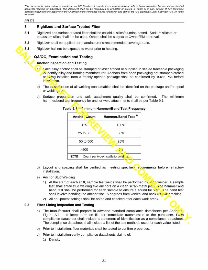
c) Surface preparation and weld attachment quality shall be confirmed. The minimum hammer/bend test frequency for anchor weld attachments shall be per Table 9.1.
Table 9.1—Minimum Hammer/Bend Test Frequency
Anchor Count Hammer/Bend Test 12
<25 100%
25 to 50 50%
50 to 500 25%
>500 5%
NOTE Count per type/installation/welder.
d) Layout and spacing shall be verified as meeting specified requirements before refractory installation.
e) Anchor Stud Welding
1) At the start of each shift, sample test welds shall be performed by each welder. A sample test shall entail stud welding five anchors on a clean scrap metal plate. The hammer and bend test shall be performed for each sample to ensure a sound full weld. The bend test shall involve bending the anchor tine 15 degrees from vertical and back without cracking.
2) All equipment settings shall be noted and checked after each work break.
9.2 Fiber Lining Inspection and Testing
a) The manufacturer shall prepare in advance standard compliance datasheets per Annex A, Figure A.1, and keep them on file for immediate transmission to the purchaser. Each compliance datasheet shall include a statement of identification as a compliance datasheet. The compliance datasheet shall include a list of the test methods used for each value listed.
b) Prior to installation, fiber materials shall be tested to confirm properties.
c) Prior to installation verify compliance datasheets claims of:
1) Density
BALLOT DRAFT. FOR REVIEW AND COMMENT ONLY.
This document is under review as revision to an API Standard; it is under consideration within an API technical committee but has not received all approvals required for publication. This document shall not be reproduced or circulated or quoted, in whole or in part, outside of API committee activities except with the approval of the Chairman of the committee having jurisdiction and staff of the API Standards Dept. Copyright API. All rights reserved.
API 976
22
2) Chemical composition
3) Check blanket/module dimensions
d) Sample/testing frequency per material to be installed shall be:
1) Three (3) samples for greater than 1000 pieces (e.g, module or blanket roll).
2) One (1) sample for less than 1000 pieces.
3) For AES fiber, the manufacturer shall provide evidence that the fiber is exempt from carcinogenic classification per Note Q of EU Commission Directive 97/69/EC.
9.3 Installation Workmanship for Fiber Linings
a) Installation drawings and procedures shall be available at the job site and reviewed by installation personnel prior to work start.
b) Anchors, hardware and materials shall be dimensionally checked and material composition verified to confirm compliance with the work specification.
c) Layout of anchors and hardware shall be plumb, level, and compliant with specification tolerances.
d) Special geometries; such as corners, burner blocks, view ports, penetrations through the lining, and terminations with other refractory systems; shall be confirmed to be constructed according to specification.
e) The anchor or stud pattern layout should account for the hot-face layer anchor requirements. Independent anchor patterns for backup layers may be needed.
f) In a layered blanket system, joints shall be tight or overlapped, as specified.
g) Prior to shell coating application, the surface shall be prepared per specification. Coating application shall be expedited to avoid flash rusting.
h) Prior to shell coating application, anchors and anchor threads shall be protected from overspray.
i) Blankets shall not be stretched.
j) Butt joints between blankets shall have specified compression.
k) Hot face blanket layers shall be installed in lengths no less than 1219 mm (4 ft), and no greater than 3810 mm (12.5 ft).
l) In board and blanket systems, the hot-face board shall be tight against the underlying blanket with 12 mm to 25 mm (½ in. to 1 in.) compression in the blanket.
m) Anchor retaining washers are installed and locked. When specified, the washers shall be protected with wrapped blanket covers.
n) Hot-face layers of board shall be installed with tight butt joints.
o) Modules are tightly installed per specification before the banding is removed (if applicable).
p) Modules are tamped-out per manufacturer’s specification with no gaps at the joints.
q) Module batten strips may be cut in single layer or folded as per manufactured design.
r) Module orientation is correct per specification/drawings (parquet versus soldier course).
s) Only specified cements and rigidizers shall be used.
t) Small and irregular openings shall be filled with blanket or pumpable AES/RCF fiber.
BALLOT DRAFT. FOR REVIEW AND COMMENT ONLY.
This document is under review as revision to an API Standard; it is under consideration within an API technical committee but has not received all approvals required for publication. This document shall not be reproduced or circulated or quoted, in whole or in part, outside of API committee activities except with the approval of the Chairman of the committee having jurisdiction and staff of the API Standards Dept. Copyright API. All rights reserved.
API 976
23
10 Preparation for Shipment 10.1 For shop and field-applied linings, packaging shall prevent damage to lining due to physical
abuse, rain, and wind effects during transportation and storage.
10.2 For shop-lined fiber refractory sections, shrink wrapping of lined sections is required.
10.3 The vendor shall identify on the drawings the maximum number of shop-lined sections that can be stacked and orientation of sections for shipping and storage purposes.
10.4 The installer (refractory) shall be responsible for all repairs of refractory linings which are damaged while within their control.
BALLOT DRAFT. FOR REVIEW AND COMMENT ONLY.
This document is under review as revision to an API Standard; it is under consideration within an API technical committee but has not received all approvals required for publication. This document shall not be reproduced or circulated or quoted, in whole or in part, outside of API committee activities except with the approval of the Chairman of the committee having jurisdiction and staff of the API Standards Dept. Copyright API. All rights reserved.
API 976
24
Annex A (normative)
Refractory Compliance Data Sheet
A.1 Scope
This Annex describes the contents of and the requirements for compliance data sheets produced by refractory manufacturers.
A.2 Definition
Compliance datasheet—lists physical and chemical properties for a specified refractory material that are
warranted by the manufacturer to be met if and when the product is tested by the listed procedure.
A.3 Application
Compliance data sheets are applicable to certification and qualification testing of refractory materials. They may also be used as a part of laboratory and technician qualification procedures.
A.4 Requirements
A.4.1 Compliance data sheets shall be developed for any refractory material commonly used in or marketed to the refining and petrochemical Industry. They may be developed for any refractory material. Each compliance data sheet shall include a statement of identification as a compliance data sheet.
A.4.3 Standard compliance data sheets shall include values as defined in Table A.1 for fiber refractories.
BALLOT DRAFT. FOR REVIEW AND COMMENT ONLY.
This document is under review as revision to an API Standard; it is under consideration within an API technical committee but has not received all approvals required for publication. This document shall not be reproduced or circulated or quoted, in whole or in part, outside of API committee activities except with the approval of the Chairman of the committee having jurisdiction and staff of the API Standards Dept. Copyright API. All rights reserved.
API 976
25
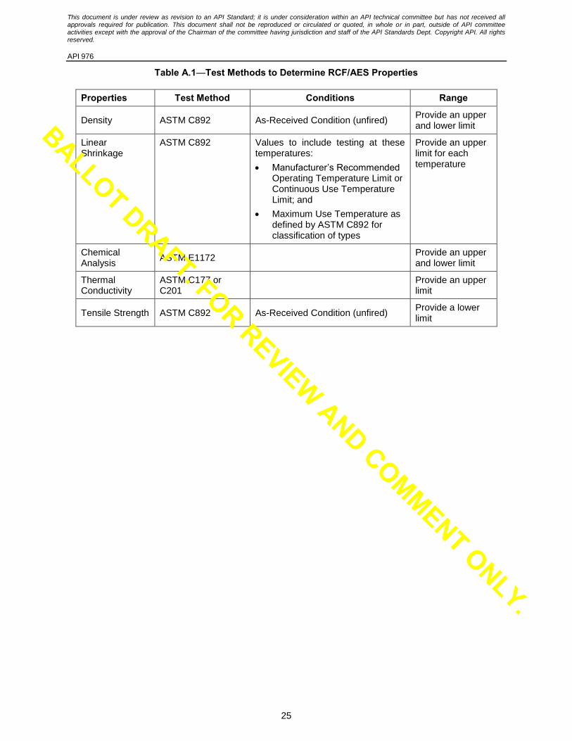
Table A.1—Test Methods to Determine RCF/AES Properties
Properties Test Method Conditions Range
Density ASTM C892 As-Received Condition (unfired) Provide an upper and lower limit
Linear Shrinkage
ASTM C892 Values to include testing at these temperatures:
Manufacturer’s Recommended Operating Temperature Limit or Continuous Use Temperature Limit; and
Maximum Use Temperature as defined by ASTM C892 for classification of types
Provide an upper limit for each temperature
Chemical Analysis
ASTM E1172 Provide an upper and lower limit
Thermal Conductivity
ASTM C177 or C201
Provide an upper limit
Tensile Strength ASTM C892 As-Received Condition (unfired) Provide a lower limit
BALLOT DRAFT. FOR REVIEW AND COMMENT ONLY.
This document is under review as revision to an API Standard; it is under consideration within an API technical committee but has not received all approvals required for publication. This document shall not be reproduced or circulated or quoted, in whole or in part, outside of API committee activities except with the approval of the Chairman of the committee having jurisdiction and staff of the API Standards Dept. Copyright API. All rights reserved.
API 976
26
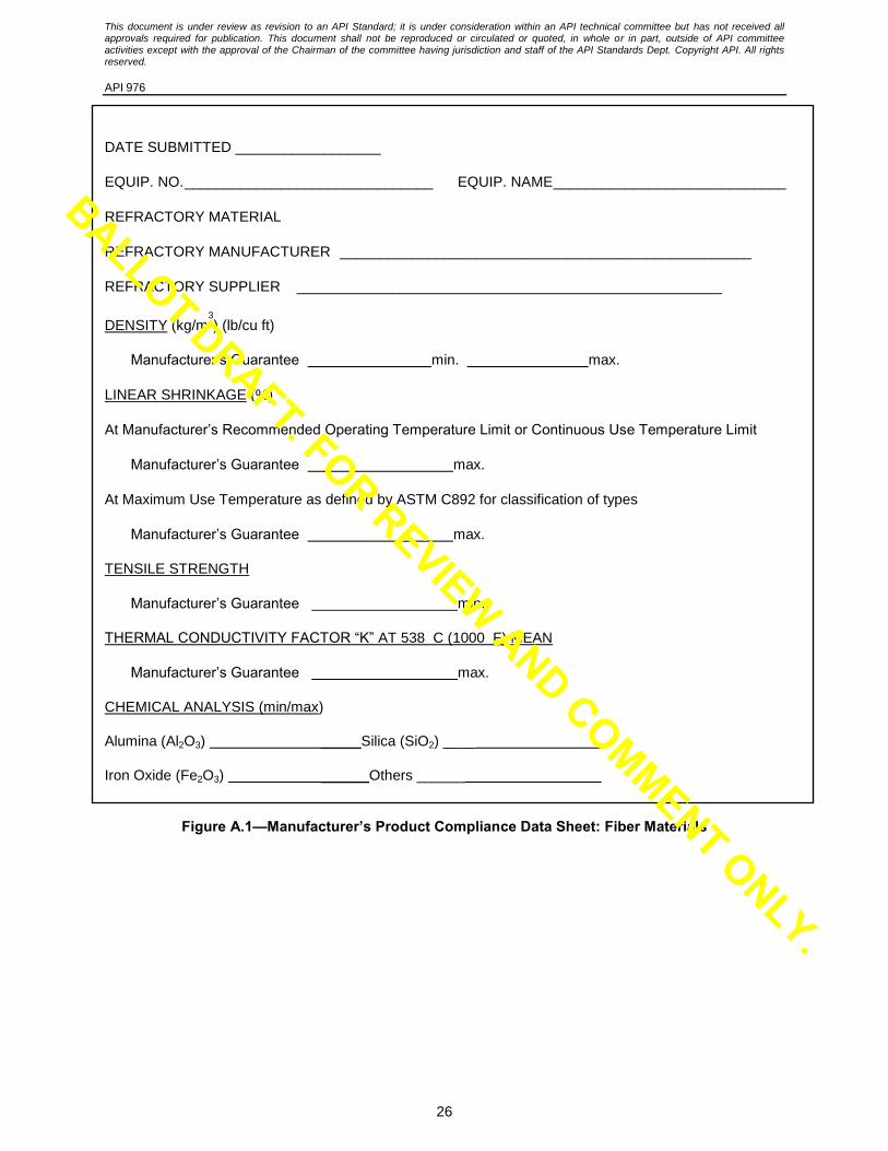
DATE SUBMITTED __________________
EQUIP. NO. _______________________________ EQUIP. NAME _____________________________
REFRACTORY MATERIAL
REFRACTORY MANUFACTURER ___________________________________________________
REFRACTORY SUPPLIER _____________________________________________________
DENSITY (kg/m3
) (lb/cu ft)
Manufacturer’s Guarantee min. max.
LINEAR SHRINKAGE (%)
At Manufacturer’s Recommended Operating Temperature Limit or Continuous Use Temperature Limit
Manufacturer’s Guarantee max.
At Maximum Use Temperature as defined by ASTM C892 for classification of types
Manufacturer’s Guarantee max.
TENSILE STRENGTH
Manufacturer’s Guarantee min.
THERMAL CONDUCTIVITY FACTOR “K” AT 538 C (1000 F) MEAN
Manufacturer’s Guarantee max.
CHEMICAL ANALYSIS (min/max)
Alumina (Al2O3) _____Silica (SiO2) ____
Iron Oxide (Fe2O3) ______Others ______
Figure A.1—Manufacturer’s Product Compliance Data Sheet: Fiber Materials
BALLOT DRAFT. FOR REVIEW AND COMMENT ONLY.
This document is under review as revision to an API Standard; it is under consideration within an API technical committee but has not received all approvals required for publication. This document shall not be reproduced or circulated or quoted, in whole or in part, outside of API committee activities except with the approval of the Chairman of the committee having jurisdiction and staff of the API Standards Dept. Copyright API. All rights reserved.
API 976
27
Annex B (informative)
Suggested Refractory Inspector Minimum Competency Requirements
B1 Suggested Refractory Inspector Minimum Competencies
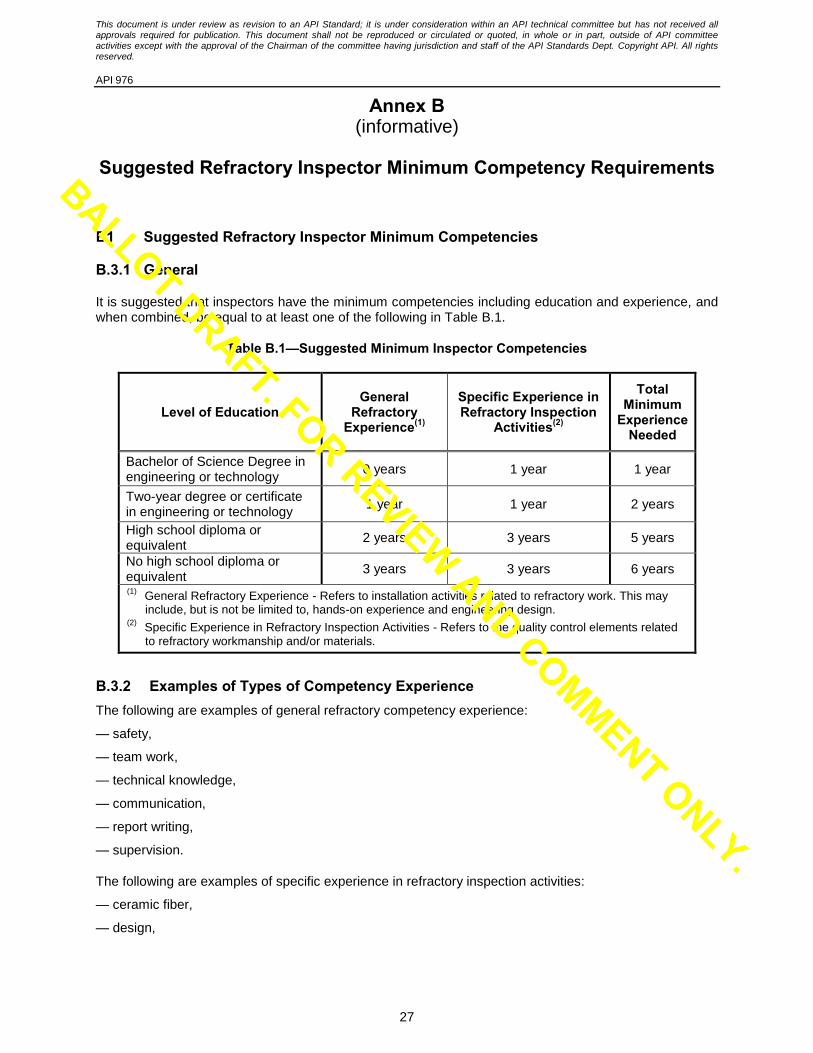
B.3.1 General
It is suggested that inspectors have the minimum competencies including education and experience, and when combined, be equal to at least one of the following in Table B.1.
Table B.1—Suggested Minimum Inspector Competencies
Level of Education General
Refractory Experience(1)
Specific Experience in Refractory Inspection
Activities(2)
Total Minimum
Experience Needed
Bachelor of Science Degree in engineering or technology
0 years 1 year 1 year
Two-year degree or certificate in engineering or technology
1 year 1 year 2 years
High school diploma or equivalent
2 years 3 years 5 years
No high school diploma or equivalent
3 years 3 years 6 years
(1) General Refractory Experience - Refers to installation activities related to refractory work. This may
include, but is not be limited to, hands-on experience and engineering design. (2)
Specific Experience in Refractory Inspection Activities - Refers to the quality control elements related to refractory workmanship and/or materials.
B.3.2 Examples of Types of Competency Experience
The following are examples of general refractory competency experience:
— safety,
— team work,
— technical knowledge,
— communication,
— report writing,
— supervision.
The following are examples of specific experience in refractory inspection activities:
— ceramic fiber,
— design,
BALLOT DRAFT. FOR REVIEW AND COMMENT ONLY.
This document is under review as revision to an API Standard; it is under consideration within an API technical committee but has not received all approvals required for publication. This document shall not be reproduced or circulated or quoted, in whole or in part, outside of API committee activities except with the approval of the Chairman of the committee having jurisdiction and staff of the API Standards Dept. Copyright API. All rights reserved.
API 976
28
— brick,
— gunite,
— laboratory experience,
— shotcrete,
— ramming,
— vibratory casting,
— pump casting,
— self-leveling castables.
BALLOT DRAFT. FOR REVIEW AND COMMENT ONLY.