regression verification for programmable logic controller
TRANSCRIPT

Karlsruhe Reports in Informatics 2015,6 Edited by Karlsruhe Institute of Technology, Faculty of Informatics
ISSN 2190-4782
Regression Verification for
Programmable Logic Controller Software
Bernhard Beckert, Mattias Ulbrich, Birgit Vogel-Heuser, Alexander Weigl
2015
KIT – University of the State of Baden-Wuerttemberg and National
Research Center of the Helmholtz Association

Please note: This Report has been published on the Internet under the following Creative Commons License: http://creativecommons.org/licenses/by-nc-nd/3.0/de.

Regression Verification forProgrammable Logic Controller Software
Bernhard Beckert1, Mattias Ulbrich1,Birgit Vogel-Heuser2, and Alexander Weigl1
1 Karlsruhe Institute of Technology, [email protected], [email protected], [email protected]
2 Technische Universitat Munchen, [email protected]
Abstract. Automated production systems are usually driven by Pro-grammable Logic Controllers (PLCs). These systems are long-living – yethave to adapt to changing requirements over time. This paper presents anovel method for regression verification of PLC code, which allows one toprove that a new revision of the plant’s software does not break existingintended behavior.Our main contribution is the design, implementation, and evaluation ofa regression verification method for PLC code. We also clarify and definethe notion of program equivalence for reactive PLC code. Core elementsof our method are a translation of PLC code into the SMV input languagefor model checkers, the adaptation of the coupling invariants concept toreactive systems, and the implementation of a toolchain using a modelchecker supporting invariant generation.We have successfully evaluated our approach using the Pick-and-PlaceUnit benchmark case study.
Keywords: regression verification, symbolic model checking, automa-ted production systems, programmable logic controllers (PLC)
1 Introduction
Motivation and Topic. Automated production systems [34], such as industrialplants and assembly lines, are usually driven by Programmable Logic Controllers(PLCs). These computing devices are specially tailored to controlling automatedproduction systems in safety-critical realtime environments. A malfunction maycause severe damage to the system itself or to the payload, or even harm personswithin the reach of the system.
The topic of this paper is how to formally verify correctness of the softwarepart of such systems, i.e., the PLC. To be precise, we focus on regression ver-ification of PLC code – as opposed to proving that the PLC code satisfies afunctional specification or to proving that the whole production system workscorrectly. That is, we verify that a version of PLC code after an evolution stepshows the same reactive input/output behavior as the old one – allowing onlydesired deviations that are formally specified. The aim of regression verifica-tion is to formally prove that existing (good) behavior is retained during systemevolution. The old version serves as specification for the new one.
Our approach and contribution. This work contributes to the field of formalPLC verification by defining a notion of reactive conditional and reactive rela-tional equivalence together with a proof methodology, also in the presence of

2 B. Beckert, M. Ulbrich, B. Vogel-Heuser, A. Weigl
environment models. Our main contribution is the design, implementation, andevaluation of a regression verification method for PLC code.
A core element of our verification method is a translation of PLC code intothe SMV input language for model checkers. Using this translation on both theold and the new software revision, we can construct a formula expressing thatintended behavior is retained. We target PLC code written in the two languagesStructured Text (ST) and Sequential Function Chart (SFC), which are part ofIEC 61131, the industry standard for PLC software [19]; an adaptation to otherlanguages is easily possible.
A further core element is the use of a model checker supporting invariantgeneration. It is an important insight that this allows the automatic generationof coupling invariants, which are a useful tool for efficient regression verification.Accordingly, we have adapted the concept of coupling invariants to the world ofreactive systems. And we have implemented our approach in a toolchain usingthe model checker nuXmv [9]. It supports techniques for predicate abstractionand invariant generation by interpolant inspection [7, 24].
As full equivalence of PLC code revisions is not the goal in many cases, wehave defined and implemented extensions where the behavior of the new coderevision may deviate under certain specified conditions and in specified ways.
We have successfully evaluated our approach using the Pick-and-Place Unit,a benchmark case study for the evolution of automated production systems withseveral evolution scenarios [35]. We were able to demonstrate our method’s feasi-bility for practical evolution scenarios and its ability to uncover regression bugs.
PLCs execute their software in cycles with fixed cycle time. Consequently,PLC code can only cause timing problems if its execution time exceeds the cycletime. Otherwise, the code’s exact execution time is irrelevant. Thus, we assumethat the cycle time constraint is ensured by other techniques, and we do notconsider exact execution time in our method.
Advantages of regression verification for PLC code. The main advantage of re-gression verification is that no functional or behavioral specification is needed(besides the old code version). In addition, regression verification is particularlywell suited for the application area of software in automated production systemsfor the following reasons.
Automated production systems are designed for long deployment phases,often spanning several decades. But the requirements on production systemschange over time. New types of products are to be manufactured. Systems areupgraded to increase throughput or to keep up with technological development.Moreover, flaws in the controlling software or the hardware design may have to befixed. Production systems therefore frequently evolve during their lifetime. Thus,methods and means to safely update their hardware and software – includingtheir PLCs – are of great importance. One has to ensure that a revision doesnot break existing intended behavior.
As opposed to (regression) testing, regression verification provides an equiv-alence proof for all possible inputs and not just for individual test cases. Also,while regression testing of PLC software requires either a hardware testbed oran executable hardware model, this is not needed for regression verification. Itsuffices to provide a formal description of how the hardware has changed duringthe evolution step (if the hardware has changed at all).
PLC systems can grow rather large, making a (non-regression) correctnessverification challenging for fully automatic verification and bisimuation checkers.
Regression Verification for PLC Software 3
ToMagazine
Lift := FALSE
Turn := left
Pickup
Lift := TRUE
Turn := stop
ToConveyor
Turn := right
Finish
Lift := FALSE
Turn := stop
I ToMagazine
A
TRUE
B
TRUE
ToMagazine
Lift := FALSE
Turn := left
metallic := M
Pickup
Lift := TRUE
Turn := stop
ToConveyor
Turn := right
ToStamp
Turn := left
Stamping
Lift := FALSE
Turn := stop
metallic := FALSE
Finish
Lift := FALSE
Turn := stop
I Pickup
A
¬metallic metallic
B C
I ToMagazine
stampedTRUE
(a) (b)
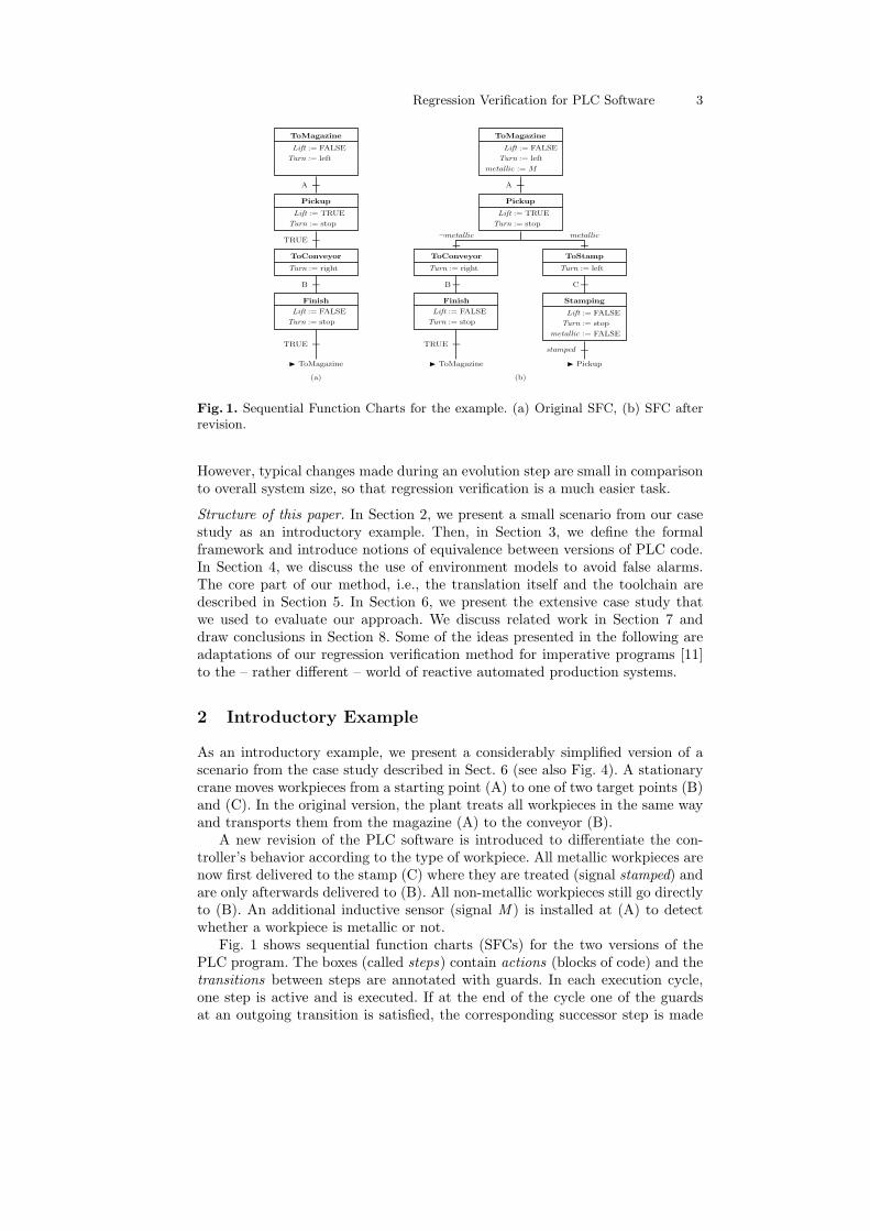
Fig. 1. Sequential Function Charts for the example. (a) Original SFC, (b) SFC afterrevision.
However, typical changes made during an evolution step are small in comparisonto overall system size, so that regression verification is a much easier task.
Structure of this paper. In Section 2, we present a small scenario from our casestudy as an introductory example. Then, in Section 3, we define the formalframework and introduce notions of equivalence between versions of PLC code.In Section 4, we discuss the use of environment models to avoid false alarms.The core part of our method, i.e., the translation itself and the toolchain aredescribed in Section 5. In Section 6, we present the extensive case study thatwe used to evaluate our approach. We discuss related work in Section 7 anddraw conclusions in Section 8. Some of the ideas presented in the following areadaptations of our regression verification method for imperative programs [11]to the – rather different – world of reactive automated production systems.
2 Introductory Example
As an introductory example, we present a considerably simplified version of ascenario from the case study described in Sect. 6 (see also Fig. 4). A stationarycrane moves workpieces from a starting point (A) to one of two target points (B)and (C). In the original version, the plant treats all workpieces in the same wayand transports them from the magazine (A) to the conveyor (B).
A new revision of the PLC software is introduced to differentiate the con-troller’s behavior according to the type of workpiece. All metallic workpieces arenow first delivered to the stamp (C) where they are treated (signal stamped) andare only afterwards delivered to (B). All non-metallic workpieces still go directlyto (B). An additional inductive sensor (signal M ) is installed at (A) to detectwhether a workpiece is metallic or not.
Fig. 1 shows sequential function charts (SFCs) for the two versions of thePLC program. The boxes (called steps) contain actions (blocks of code) and thetransitions between steps are annotated with guards. In each execution cycle,one step is active and is executed. If at the end of the cycle one of the guardsat an outgoing transition is satisfied, the corresponding successor step is made

4 B. Beckert, M. Ulbrich, B. Vogel-Heuser, A. Weigl
the active step. Otherwise the current step remains active and is repeated in thenext cycle. In the example, the actions assign values to output (Turn,Lift) andinternal variables (metallic, stamped). The guard conditions are Boolean inputvariables corresponding to sensor input (A,B,C represent input from sensors forcrane position) and Boolean internal variables (metallic). In the original SFC,the steps correspond to the actions of moving the crane to the magazine, pickingup the workpiece, moving the crane to the conveyor, and putting down theworkpiece. In the revised SFC, there is a case distinction on metallic, and twonew steps have been added to move metallic pieces to the stamp and droppingthem there. After the workpiece has been stamped, the internal variable metallicis set to FALSE, and then the step Pickup becomes active, i.e., from there onthe SFC continues in the same way as if a non-metallic workpiece has just beenpicked up at (A).
Note that this is a simple example. In general, actions and guards can beconsiderably more complex and contain conditional statements and loops.
In case there are metallic workpieces, the behavior of the PLC is obviouslydifferent. But in case that only non-metallic workpieces are ever detected bysensor (M), the new software version should do the same as the old version. Sothis is a scenario for using regression verification to prove conditional equivalencefor the unchanged case.
3 Formalizing Equivalence of PLC Programs
We define a formal framework for the behavior of reactive PLC software togetherwith adequate notions of equivalence between them.
There are various possibilities for defining system boundaries when model-ing an automated production system. One can model the whole system or onlyindividual components. Even when focusing on the PLC, one could still includemodels of peripheral hardware components like connecting data buses. However,our method concentrates on the software that runs on the controller and disre-gards all effects outside the software for now. Sect. 4 discusses measures to takethe environment into consideration.
PLCs are reactive systems with a cyclic data processing behavior, repeatingthe same control procedure indefinitely. A PLC cycle typically consists of thefollowing steps: (1) read input values, (2) execute task(s), (3) write output values,(4) wait. As reactive systems, PLCs require a notion of equivalence that involvestraces, which means that if the old and the new revision are presented with thesame sequence of input sensor readings, they must produce the same sequenceof actuator output stimuli.
We call the piece of code that is executed cyclically on the controller a PLCprogram. A PLC program P consists of the instructions Π to be executed anda set of declarations ∆ of input, output and state variables. In the introductoryexample in Sect. 2, the declarations of the program contain the Boolean input(sensor) variables A,B,C and M ; Lift and Turn are output (actuator) variables(the declarations are not shown in Fig. 1).
The internal state of a PLC program consists of an assignment of valuesto its state variables (in the example, the Boolean variable metallic). There isalways an implicit state variable active step storing which of the steps in theSFC program is active. The declarations ∆ induce an input value space I, anoutput value space O, and state space S, each as the Cartesian product of

Regression Verification for PLC Software 5
the value ranges of the corresponding program variables. In the example, I isbool × bool × bool × bool . We assume the initial values of state variables to bedetermined by their declarations (using default values in case no initial value isgiven), i.e., the initial state s0 ∈ S is fixed by ∆.
Definition 1 (Semantics of PLC programs). The semantics ρ(P ) of a PLCprogram P is a state transition function ρ(P ) : S × I → S ×O.
The semantics ρ(P ) depends on the instructions in Π. These may read from thestate and the input variables (in S and I) and write to the state variables andto the output variables (in S and O).
To be able to consider the effects of a PLC program over time, the abovedefinition needs to be extended to sequences of inputs and outputs. We denoteinfinite sequences of elements in I (ω-words) with i ∈ Iω; their components areaccessed using subscript indices, i.e., i = 〈i1, i2, . . .〉. The PLC program as astateful system needs an initial state s0 from which it is launched. As mentionedabove, s0 is determined by the variable declarations ∆.
Definition 2 (Trace Semantics of PLC Programs). The behavior b(P ) ofa PLC program P with initial state s0 ∈ S is the function b(P ) : Iω → Oω
defined by b(P )(〈i1, i2, . . .〉) = 〈o1, o2, . . .〉 where (sn, on) = ρ(P )((sn−1, in)
)for
all n ∈ N≥1.
This definition says that starting from the initial state s0, the PLC program isexecuted repeatedly, applying in each cycle ρ(P ) to its current state sn−1 andthe input tuple in ∈ I to produce the output tuple on ∈ O and the new state sn.
Trace semantics use the internal state in the definition, but when taking anoutside look at the semantics, it defines input/output behavior and does notmake statements about the internal state space. This is relevant for our initialdefinition of equivalence where it is required that two programs produce identicaltraces.
Definition 3 (Trace Equivalent PLC Programs). Two PLC programs P,Qwith the same declarations ∆P = ∆Q are called perfectly equivalent if theyproduce the same output sequence when presented with the same input sequence,i.e., b(P )(i) = b(Q)(i) for all i ∈ Iω.
They are called conditionally equivalent modulo the condition ϕ : Iω → boolif they produce the same result for all input sequences that satisfy condition ϕ,i.e., if ϕ(i) then b(P )(i) = b(Q)(i) for all i ∈ Iω.
It is intuitively evident that replacing a PLC with a new revision whose pro-gram is trace equivalent to the original program does not change the observablebehavior of the plant, provided everything else remains unchanged and timingeffects are left aside.
Conditional equivalence relaxes the strict notion of perfect equivalence byrequiring the same output sequence only if a condition ϕ holds. Intuitively thismeans that replacing a PLC with a new revision whose program is conditionallyequivalent to the original program modulo ϕ does not change the plant’s behaviorat least for those traces where all sensor signal readings satisfy ϕ.
The example given in Sect. 2 is an example of conditional equivalence: Themodified controller software (Fig. 1) is conditionally equivalent to the origi-nal version modulo the condition that every encountered workpiece is non-metallic. This condition can be expressed in Linear Temporal Logic (LTL [26])

6 B. Beckert, M. Ulbrich, B. Vogel-Heuser, A. Weigl
as ϕnon−metallic(i) = G¬M recalling that M is the signal from the inductivemetal detection sensor.
Perfect and conditional equivalence use equality to compare input and outputtraces. There are many cases, however, where full equality is not required or notappropriate. Equality of outputs may not be required for outputs relating tonon-critical components of the system. And equality may not be the appropriaterelation if the sensors and/or actuators of the plant have been modified, and thusthe input/output spaces of the program revisions are different. It is thereforenecessary to generalize the equivalence notion. To this end, we introduce binaryrelations ∼in and ∼out .
Definition 4 (Relational Equivalence of Controllers). Two PLC programsP,Q with declarations ∆P resp. ∆Q are called relationally equivalent modulo re-lations ∼in⊆ IωP ×IωQ and ∼out : OωP ×OωQ if they produce related output sequenceswhen presented with related input sequences, i.e.,
if i ∼in i′ then b(P )(i) ∼out b(Q)(i′) for all i ∈ IωP , i′ ∈ IωQ.
Note that conditional equivalence can be expressed as relational equivalence(if IP = IQ and OP = OQ) by choosing i = i′ ∧ ϕ(i) for the input relation ∼in
and o = o′ for the output relation ∼out .If a revision adds or removes existing variables from the declarations, the
canonical relations to be considered are the conjoined equalities between all sig-nals shared by both revisions (i.e., the variables in ∆P ∩ ∆Q). This is calledprojected equivalence. The introductory example in Sect. 2 is a projected equiv-alence if the metallic detector is assumed absent in the first version and onlyintroduced in the second. Another example of relational equivalence is shown inthe case study in Sect. 6.
4 Environment Models to Increase Precision
False alarms can occur if the two revisions of a PLC program behave differentlyon inputs that cannot actually occur in the application. For example, the cranefrom Sect. 2 can never be in more than one of the positions A,B,C at the sametime. Assuming correct working of the sensors, not more than one of the Booleaninput variables A,B,C can be true at the same time. Thus, it would be irrelevantif the two program revisions were to react differently in case A and B weresignaled simultaneously but would still be equivalent for all feasible inputs. Itis therefore sensible to add such knowledge on the possible sensor inputs asassumptions to the process and perform a conditional regression verification. Inthe example, it is possible to encode the assumption in form of the LTL conditionG(¬(A ∧B) ∧ ¬(B ∧ C) ∧ ¬(A ∧ C)).
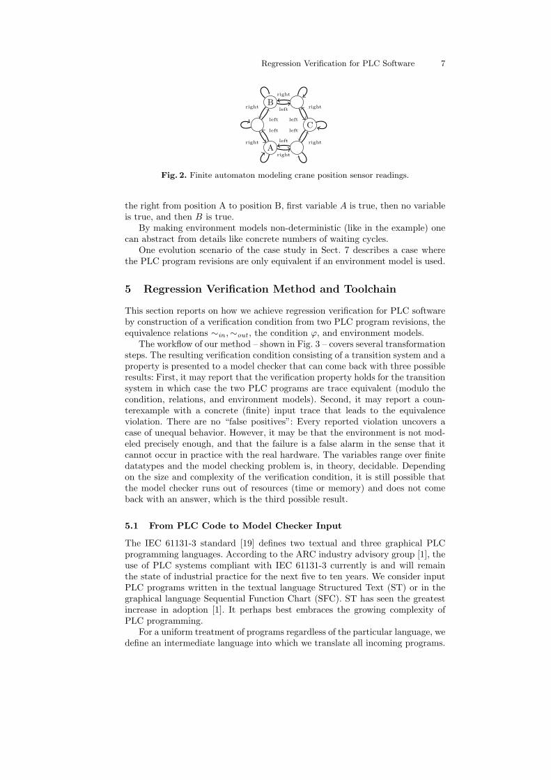
But in more involved cases, it is difficult or error-prone to express propertiesof the physical system correctly in form of conditions on the PLC inputs. Then itis better to use a model of the environment which uses output of PLC program asinput. This restricts the search space, increases precision of regression verificationand avoids false alarms. Fig. 2 depicts a model of the crane restricting the inputspace for the variables corresponding to the crane’s position. Besides the threestates for positions A, B, C in which only the corresponding PLC input variableis true, there are three intermediate states between the positions where none ofvariables is true. The crane behavior model shows that when the crane turns to
Regression Verification for PLC Software 7
A
B
Cleft
right
left
right left
right
left
right
left
rightleft
right
Fig. 2. Finite automaton modeling crane position sensor readings.
the right from position A to position B, first variable A is true, then no variableis true, and then B is true.
By making environment models non-deterministic (like in the example) onecan abstract from details like concrete numbers of waiting cycles.
One evolution scenario of the case study in Sect. 7 describes a case wherethe PLC program revisions are only equivalent if an environment model is used.
5 Regression Verification Method and Toolchain
This section reports on how we achieve regression verification for PLC softwareby construction of a verification condition from two PLC program revisions, theequivalence relations ∼in ,∼out , the condition ϕ, and environment models.
The workflow of our method – shown in Fig. 3 – covers several transformationsteps. The resulting verification condition consisting of a transition system and aproperty is presented to a model checker that can come back with three possibleresults: First, it may report that the verification property holds for the transitionsystem in which case the two PLC programs are trace equivalent (modulo thecondition, relations, and environment models). Second, it may report a coun-terexample with a concrete (finite) input trace that leads to the equivalenceviolation. There are no “false positives”: Every reported violation uncovers acase of unequal behavior. However, it may be that the environment is not mod-eled precisely enough, and that the failure is a false alarm in the sense that itcannot occur in practice with the real hardware. The variables range over finitedatatypes and the model checking problem is, in theory, decidable. Dependingon the size and complexity of the verification condition, it is still possible thatthe model checker runs out of resources (time or memory) and does not comeback with an answer, which is the third possible result.
5.1 From PLC Code to Model Checker Input
The IEC 61131-3 standard [19] defines two textual and three graphical PLCprogramming languages. According to the ARC industry advisory group [1], theuse of PLC systems compliant with IEC 61131-3 currently is and will remainthe state of industrial practice for the next five to ten years. We consider inputPLC programs written in the textual language Structured Text (ST) or in thegraphical language Sequential Function Chart (SFC). ST has seen the greatestincrease in adoption [1]. It perhaps best embraces the growing complexity ofPLC programming.
For a uniform treatment of programs regardless of the particular language, wedefine an intermediate language into which we translate all incoming programs.

8 B. Beckert, M. Ulbrich, B. Vogel-Heuser, A. Weigl
VerificationModel
Generation
SMV
Model Checker
Formalizationof equality
Environmentmodels
SMV
SymbolicExecution
ST0
Normalization
PLC code
SMV
SymbolicExecution
ST0
Normalization
PLC code
3� 7
Revision A Revision B
Fig. 3. Overview over the regression verification method.
This language is a sublanguage of ST called ST0. Despite their notational differ-ences, programs in all 61131-3 programming languages can be represented in ST0
(provided they do not have unbounded loops). PLC programs are time-critical,and they are required to finish within their cycle time. It is therefore reasonableto assume that programs do not contain loops with an unbounded number ofiterations.
The language ST0 is essentially the loop- and call-free fragment of ST re-duced to fewer, more basic datatypes. The only types of statements in ST0 areassignments and if-then-else conditionals. During normalization to ST0, loopsare fully unwound and function block invocation are inlined. We require that forall loops a bound for the number of iterations can be statically computed fromthe code, so that this unwinding is always possible. Inlining is also feasible sincerecursion is not featured in the IEC 61131-3 framework.
To demonstrate our method, we implemented such translations to ST0 forST and SFC. The translation from SFC to ST0 is problematic since the standardleaves many semantical issues unanswered. We resolved this issue by followingthe formal semantics for SFCs given in [4] when translating SFC to ST0.
The normalized code in ST0 is symbolically executed to derive a state transi-tion system as model checker input. Naıve implementations of symbolic executionor other verification condition generation algorithms like weakest preconditioncalculus may produce program representations whose size is exponential in thatof the original program. This is due to an explicit enumeration of all possiblepaths through the program. Since ST0 programs that result from translating SFCcode involve many consecutive and nested if-statements to encode the originalstate machine, the number of paths through the program is huge and explicitlyenumerating them is infeasible. For example, the last scenario (Ev14) of our

Regression Verification for PLC Software 9
case study (Sect. 6) yields some 13 billion paths, such that the resulting proofobligation would not fit into the available memory.
Instead we produce a smaller program representation by not explicitly enu-merating all paths but following the concept of Φ-nodes (known from staticsingle assignment [10]) to merge the effects of the branches of an if-statement.This approach is also similar to the weakest-precondition-calculus optimizationpresented in [12].
During symbolic execution, a symbolic variable map V : Vars∆ → Terms∆is modified, which assigns to all declared variables their current symbolic value(a term). Stmt∆ denotes the set of all ST0-statements, and tV is the symbolicevaluation of an expression t in the symbolic variable assignment V.
Definition 5 (Symbolic Execution). Symbolic execution of ST0 code is theoperator se : (Vars∆ → Terms∆)× Stmt∆ → (Vars∆ → Terms∆) with
se(V, v := t) := V[v := tV ]se(V, S;T ) := se(se(V, S), T )
se(V, if c then S else T ) := Φ(cV , se(V, S), se(V, T ))
where the map Φ(c,V1,V2) : Vars∆ → Terms∆ is, for all v ∈ Vars∆, defined by:
Φ(c,V1,V2)(v) :=
{V1(v) if V1(v) = V2(v)if c then V1(v) else V2(v) otherwise
Essentially, this transformation moves the conditions of if-then-else statementsinto the variable assignment in form of if-then-else expressions. While this proce-dure cannot guarantee that the result is not exponentially larger than the input,our experiences show that the results are acceptable in practice.
The state transition system for a program P is computed as follows: Theoperator se is applied to the instructions Π of P with the identity mapping id∆as the starting point, resulting in the symbolic variable map se(Π, id∆). Thesymbolic assignments in this map provide the state transition definitions for thestate variables and the output terms for the output variables.
5.2 Encoding Regression Verification
The proof obligation handed to the symbolic model checker consists of a statetransition system and a property that is to be proved an invariant for it. Thestate transition system is a composition of the two systems that result fromtranslating the two PLC program revisions P and Q and the models for theenvironment as introduced in Sect. 4.
All variables of the input spaces IP and IQ make up the input variables ofthe combined model. If ∆P and ∆Q share common input variables, these canalso be shared in the combined model, thus reducing the input state space sizefor model checking.
If the sensor readings are constrained by an environment model, the inputsignals of that model are input signals of the entire state transition system whileinput signals of the PLC programs corresponding to sensor readings are takenfrom the outputs of the environment model. In the example environment modelfor the crane positions (Fig. 2), the PLC program takes the three inputs A,B,Cfrom position sensors, while the composed verification model merely takes as

10 B. Beckert, M. Ulbrich, B. Vogel-Heuser, A. Weigl
input the indeterministic choice whether to remain in the current model stateor whether to move on a step. This has two effects: (1) The input space size isreduced and (2) the modeling is more precise.
The condition ϕ from Def. 3 and the input and output relations ∼in ,∼out
from Def. 4 make up the invariant that is part of the model checking proofobligation. In the current version of our toolchain, we require that the condition ϕcan be expressed in LTL by a formula of the form Gψ, where ψ is a propositionalformula over the input variables in IP without modal operators. That is, it mustbe possible to express the desired condition on the input sequence as a propertyof individual inputs. Correspondingly, we require that the relations ∼in ,∼out
can be expressed by LTL formulas ∼in = G τin resp. ∼out = G τout , where τinand τout are propositional formulas over the variables in IP ∪ IQ resp. OP ∪OQ.We then employ a fresh internal state variable pre : bool to model the temporalcondition within the invariant as follows:
init(pre) := true (1)next(pre) := pre ∧ ψ ∧ τin (2)invariant pre → τout (3)
The variable pre is initialized to true (1) and is invalidated (2) as soon as inputvalues violate either the condition (ψ) or the input relation (τin). If the guardedinvariant (3) holds for the transition system, then the equivalence of the twoprograms is guaranteed. What in fact is proved using the auxiliary variable preis the LTL property (¬ψ∨¬τin) R τout stating that the output relation τout musthold at least as long as neither the condition ψ nor the relation τin have beenviolated (R is the “release” operator of LTL). This entails relational equivalencebetween P and Q.
All relations and conditions occurring in our case study fall into the restrictedcategory of specifications described above. Although this is not implemented atthe moment, other classes of LTL constraints can be used in our method byencoding them as invariants along the lines of [27].
5.3 Coupling Invariants
Modern model checkers allow the application of state abstraction methods (likeIC3) to find proofs for safety properties more efficiently. Regression verificationusing symbolic model checkers with such abstractions is particularly promising,since the two software revisions are closely related if the newer one results fromthe adaptation of the older one to a new application scenario. In such cases, itis likely that the old and the new version of the program have a similar – yetnot necessary equal – encoding of their state spaces.
The upcoming abstraction theorem allows us to reason about safety proper-ties of two PLC programs P and Q using an invariant Inv : SP × SQ → boolover their state spaces SP and SQ. Such a predicate, building a bridge betweenthe state spaces, is called a coupling predicate.
Theorem 1 (Coupling Invariant Abstraction). We consider two PLC pro-grams P and Q with common input space I, common output space O, and statespaces SP and SQ. Let s0 ∈ SP and s′0 ∈ SQ be the initial states.
Then, P and Q are (perfectly) trace equivalent if and only if there exists acoupling predicate Inv : SP × SQ → bool such that, for all states s ∈ SP , s′ ∈ SQand inputs i ∈ I,

Regression Verification for PLC Software 11
1. Inv(s0, s′0) holds,2. Inv(s, s′) implies Inv(t, t′),3. Inv(s, s′) implies o = o′,
where (t, o) = ρ(P )(s, i) and (t′, o′) = ρ(Q)(s′, i).
Similar theorems can be formulated for PLC programs that are relationallyequivalent.
The more similar the state space encodings of the old and the new programversion are, the closer the coupling predicate is to equality on the state spaces.This becomes evident when a PLC program P is verified against itself. In thiscase, the equality relation itself can be used as coupling predicate and satisfiesthe conditions in Theorem 1 regardless of what P computes.
Development of PLC programs is often an incremental process, i.e., the newrevision results from a modification of the code in the old version. Often, partsof the state are not affected by the changes (and behave like in the old revision)whereas other parts are affected. An inductive invariant implying equivalencethen comprises equality between the unmodified state variables, and a moregeneral coupling invariant must be generated only for the affected variables.
The regression verification method using invariants is complete, but the userof the verification tool would have to find and formalize all coupling invariantswhich can be large and unintuitive. Instead, we rely upon the capabilities of state-of-the-art symbolic model checkers to automatically infer inductive invariants.In our case, the required system invariant (3) (which usually is not inductiveitself) is used as a starting point for an interpolant-based search for a strongerinductive invariant that implies the one given in the problem specification.
We show in our case study that even with large state spaces, this stateabstraction mechanism allows us to prove equivalence of non-trivial programs.The model checker nuXmv is capable of coming up with the required couplingpredicates using Incremental Construction of Inductive Clauses for IndubitableCorrectness (IC3) [7,24]. If this invariant generation mechanism is switched off,the tool relies on more traditional symbolic model checking techniques. Then,even the smaller ones of the problems in the case study could not be solved.
In cases where the search for an inductive invariant takes too long, parts ofthe coupling invariant can be specified manually (within (3)) – the workload forthe invariant generation can thus be shared between user and model checker.
6 Case Study
We have evaluated our approach by applying it to the benchmark evolutionscenarios of the Pick-and-Place Unit (PPU), which is illustrated in Fig. 4. ThePPU is an open case study for the machine manufacturing domain [35]. Despitebeing a bench-scale, academic demonstration case, the PPU is complex enoughto demonstrate selected challenges that arise during engineering of automatedproduction systems. To explore evolution in this context, sixteen scenarios (i.e.,variants of the PPU) covering different aspects of evolution have been defined [22,36]. There are both pure software changes as well as changes that incorporateadaptations to the mechanics and automation hardware of the PPU.
For all of the scenarios developed for the PPU, both the structure and thebehavior of the PPU are documented using the Systems Modeling Language
12 B. Beckert, M. Ulbrich, B. Vogel-Heuser, A. Weigl
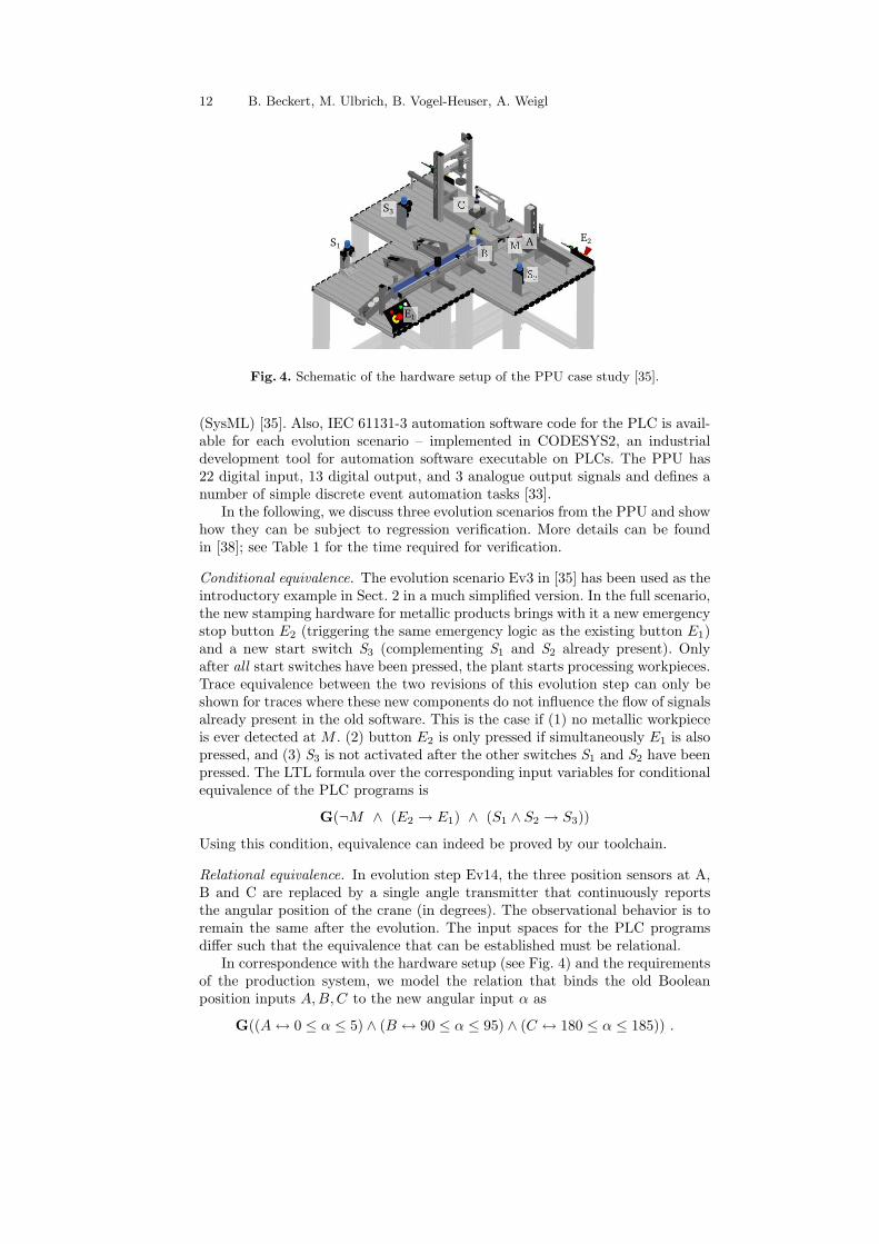
Fig. 4. Schematic of the hardware setup of the PPU case study [35].
(SysML) [35]. Also, IEC 61131-3 automation software code for the PLC is avail-able for each evolution scenario – implemented in CODESYS2, an industrialdevelopment tool for automation software executable on PLCs. The PPU has22 digital input, 13 digital output, and 3 analogue output signals and defines anumber of simple discrete event automation tasks [33].
In the following, we discuss three evolution scenarios from the PPU and showhow they can be subject to regression verification. More details can be foundin [38]; see Table 1 for the time required for verification.
Conditional equivalence. The evolution scenario Ev3 in [35] has been used as theintroductory example in Sect. 2 in a much simplified version. In the full scenario,the new stamping hardware for metallic products brings with it a new emergencystop button E2 (triggering the same emergency logic as the existing button E1)and a new start switch S3 (complementing S1 and S2 already present). Onlyafter all start switches have been pressed, the plant starts processing workpieces.Trace equivalence between the two revisions of this evolution step can only beshown for traces where these new components do not influence the flow of signalsalready present in the old software. This is the case if (1) no metallic workpieceis ever detected at M . (2) button E2 is only pressed if simultaneously E1 is alsopressed, and (3) S3 is not activated after the other switches S1 and S2 have beenpressed. The LTL formula over the corresponding input variables for conditionalequivalence of the PLC programs is
G(¬M ∧ (E2 → E1) ∧ (S1 ∧ S2 → S3))
Using this condition, equivalence can indeed be proved by our toolchain.
Relational equivalence. In evolution step Ev14, the three position sensors at A,B and C are replaced by a single angle transmitter that continuously reportsthe angular position of the crane (in degrees). The observational behavior is toremain the same after the evolution. The input spaces for the PLC programsdiffer such that the equivalence that can be established must be relational.
In correspondence with the hardware setup (see Fig. 4) and the requirementsof the production system, we model the relation that binds the old Booleanposition inputs A,B,C to the new angular input α as
G((A↔ 0 ≤ α ≤ 5) ∧ (B ↔ 90 ≤ α ≤ 95) ∧ (C ↔ 180 ≤ α ≤ 185)) .

Regression Verification for PLC Software 13
In the thus defined input relation ∼in each position switch corresponds to a5◦ interval in the angular input space. This also shows that relations in ourapproach can be more complex than just a biunique mapping between values.
Using an environment model. In evolution scenario Ev6, the hardware remainsunmodified, but the software is changed to optimize the handling of non-metallicworkpieces (see [35] for details). The PLC programs before and after the opti-mization should be equivalent for traces where only metallic or only non-metallicworkpieces are detected, but the programs are not equivalent. An inspection ofthe code reveals that a condition within an SFC has been reformulated. As afirst guess one could assume that the two conditions are equivalent and use thisas condition for the conditional equivalence proof. Indeed, the equivalence proofsucceeds using that assumption (Ev6+A for both cases, Ev6+Am for metallicand Ev6+Anm for non-metallic pieces only). However, using an ad-hoc assump-tion about the input state is not satisfactory even if it could be justified by amanual inspection. Instead, a more intuitive and convincing item, an environ-ment model of the crane (essentially the one shown in Fig. 2) can be added,using which the PLC programs are proven equivalent with (Ev6+AEM) andeven without the assumption (Ev6+EM).
Results. Using our method and toolchain, automatic regression verification wassuccessful for all scenarios from the PPU case study.
Table 1 shows statistics for our experiments with the PPU. The evolutionscenarios were verified using nuXmv version 1.0.1 on an Intel Dual-Core with2.7 GHz and 4 GB RAM running OpenSUSE 12.2.
Not all evolution scenarios include a modification of the software. The sce-narios for which the equivalence verification is trivial have been omitted fromthe table. The verification times for the same problem on the same machine mayvary considerably in multiple runs due to random choices in the symbolic modelchecker which have a great impact on the verification time.
The regression verification method can not only be used for verifying equiva-lence of PLC programs up to intended differences, but unintentional differencesbetween programs can also be found using our approach. The evaluation of ourapproach revealed a few unintentional regressions in the PPU. In four cases, newintermediate code blocks are added into SFCs that cause a regression by delay-ing the system answer one cycle for each workpiece. Since the cycle time is veryshort in the PPU (4 ms), the discrepancy between the programs was not foundby testing. Moreover, regression verification discovered that a fix for a safetyviolation was not applied to an earlier version in the PPU evolution sequence.It is possible that the crane tries to grab a workpiece while it is still in motionwhich might under very unfortunate circumstances cause damages.
7 Related Work
The verification of PLC programs w.r.t. temporal logic specifications (for safety,liveness, and time properties) has been subject of a number of publications al-ready. The paper [40] gives an overview of the field, and the survey [21] discussestransformation processes for program languages to verifiable models. Varioustranslations from IEC 6113-3 languages into the input languages of model check-ers have been presented: Brinksma et al. [8] present a translation of SFCs into

14 B. Beckert, M. Ulbrich, B. Vogel-Heuser, A. Weigl
Table 1. Results of the experiments. scenario is the name of the evolution scenarioin [35], in is the size of the sensor input space in bits, state the size of the state spacein bits, min/max show the minimum and maximum time needed for verification usingnuXmv in seconds (s), minutes (m) or hours (h). +EM indicates that an environmentmodel has been used.
scenario in state min max scenario in state min max
Ev1 10 140 4 s 8 s Ev6+EM 11 299 2 m 21 mEv1+EM 12 146 7 s 12 s Ev8 20 289 13.7 m 20.9 mEv2 11 141 4 s 8 s Ev9 20 305 50.5 m 1.3 hEv3 19 246 9 s 17 s Ev10 23 365 13 s 24 sEv6+A 19 284 15.1 m 155.4 h Ev11 28 576 3.5 h 6.3 hEv6+Am 19 284 8.9 m 9.1 h Ev12 34 860 22.2 h 56.4 hEv6+Anm 19 284 18.1 m 13 h Ev13 34 1225 21.9 h 21.9 hEv6+AEM 11 299 25.7 m 104.1 h Ev14 47 1663 22.1 h 22.1 h
Promela input for the SPIN model checker [17]; De Smet et al. [28] translateall languages within IEC 61131-3 into input for the symbolic model checker Ca-dence-SMV [25]; and Bauer et al. [3] translate SFCs into timed automata to beused with UPPAAL [5]. This model checker is also used to verify properties ofcontinuous function charts (CFC) in [37]. In [4, 6] a unifying semantics for SFCis given where the ambiguities of the standard are addressed in a formal fashion.
Suflow and Drechsler [30] present a framework to verify that the same pro-gram behaves equivalently on different PLC platforms; a scenario closely relatedto ours. The authors employ a SAT solver to verify the arising proof conditions.
Strichman and Godlin [13–15,29] coined the term regression verification andpresented a verification methodology based on replacing function calls by unin-terpreted function symbols within a bounded software model checking frameworkfor C programs. In [13] they define “reactive equivalence,” which is closely re-lated to our notion of perfect trace equivalence. In earlier work [11], we presentedan automated approach to regression verification based on invariant generationusing Horn clauses. Many other approaches [2, 16, 31, 32, 39] exist to regressionverification for imperative programming languages.
Equivalence checking is an established issue for the verification of hardwarecircuits. In sequential equivalence checking the perfect trace equivalence betweenclocked circuits is analysed; see [18] or [20] for an overview. Lu and Cheng [23]present an approach based on inferred invariants, conditional or relational equiv-alence are not considered.
8 Conclusion and Future Work
We have presented a method and toolchain for the automatic regression verifica-tion of PLC software by means of a symbolic model checker. In this process, theold software revision serves as specification for the new one. Conditions can bespecified under which systems must behave equivalently, relations can be speci-fied how the equivalence is to be understood, and models of environment can beadded to make the process more precise.
Evaluation proved our method to be applicable to non-trivial PPC software.Automatic regression verification was successful for all scenarios from the PPUcase study. The evaluation also showed that the use of Φ-nodes in the translationfrom PPU code to model checking input as well as the automatic generation ofcoupling invariants is indispensable for non-trivial programs.

Regression Verification for PLC Software 15
Currently, our toolchain supports notions that compare PLC behavior cycleby cycle. Future work will allow for conditions and relations to relate variables ofdifferent cycles. Another interesting path of investigation is the use of abstrac-tions to factor out parts of PLCs that have not been touched by evolution andneed not be proved equivalent.
Acknowledgement. The authors thank Alberto Griggio for his valuable inputon the effective use of nuXmv and Vladimir Klebanov for his feedback on anearlier version of this paper.
This work was supported by the DFG (German Research Foundation) in Pri-ority Programme SPP1593: Design For Future – Managed Software Evolution.
References
1. ARC Advisory Group. PLC & PLC-based PAC worldwide outlook: Five yearmarket analysis and technology forecast through 2016, 2011.
2. G. Barthe, J. M. Crespo, and C. Kunz. Relational verification using productprograms. In Proc., Int. Symp. on Formal Methods (FM), LNCS. Springer, 2011.
3. N. Bauer, S. Engell, R. Huuck, S. Lohmann, B. Lukoschus, M. Remelhe, andO. Stursberg. Verification of PLC programs given as sequential function charts. InIntegration of Software Specification Techniques for Applications in Engineering,LNCS 3147, pages 517–540. Springer, 2004.
4. N. Bauer, R. Huuck, B. Lukoschus, and S. Engell. A unifying semantics for se-quential function charts. In Integration of Software Specification Techniques forApplications in Engineering, LNCS 3147, pages 400–418. Springer, 2004.
5. G. Behrmann, K. Larsen, O. Moller, A. David, P. Pettersson, and W. Yi. Uppaal:Present and future. In Decision and Control, 2001. Proc. of the IEEE Conf., 2001.
6. S. Bornot, R. Huuck, and B. Lukoschus. Verification of sequential function chartsusing SMV. In H. R. Arabnia, editor, PDPTA. CSREA Press, 2000.
7. A. R. Bradley. SAT-based model checking without unrolling. In Verification, ModelChecking, and Abstract Interpretation, LNCS 6538, pages 70–87. Springer, 2011.
8. E. Brinksma, A. Mader, and A. Fehnker. Verification and Optimization of a PLCControl Schedule. Software Tools for Technology Transfer, 4(1):21–33, 2002.
9. R. Cavada, A. Cimatti, M. Dorigatti, A. Griggio, A. Mariotti, A. Micheli, S. Mover,M. Roveri, and S. Tonetta. The nuXmv symbolic model checker. In CAV, LNCS8559. Springer, 2014.
10. R. Cytron, J. Ferrante, B. K. Rosen, M. N. Wegman, and F. K. Zadeck. Anefficient method of computing static single assignment form. In Proc. ACM Symp.on Principles of Programming Languages, POPL ’89. ACM, 1989.
11. D. Felsing, S. Grebing, V. Klebanov, P. Rummer, and M. Ulbrich. Automatingregression verification. In Proceedings of the 29th ACM/IEEE International Con-ference on Automated Software Engineering, ASE ’14. ACM, 2014.
12. C. Flanagan and J. B. Saxe. Avoiding exponential explosion: Generating compactverification conditions. In Principles of Programming Languages. ACM, 2001.
13. B. Godlin and O. Strichman. Inference rules for proving the equivalence of recursiveprocedures. Acta Informatica, 45(6):403–439, 2008.
14. B. Godlin and O. Strichman. Regression verification. In Proc., 46th Annual DesignAutomation Conference. ACM, 2009.
15. B. Godlin and O. Strichman. Regression verification: Proving the equivalence ofsimilar programs. Software Testing, Verification and Reliability, 23(3):241–258,2013.
16. C. Hawblitzel, M. Kawaguchi, S. K. Lahiri, and H. Rebelo. Towards modularlycomparing programs using automated theorem provers. In Proc., Int. Conf. onAutomated Deduction, LNCS 7898. Springer, 2013.

16 B. Beckert, M. Ulbrich, B. Vogel-Heuser, A. Weigl
17. G. J. Holzmann. The model checker SPIN. IEEE Transactions on software engi-neering, 23(5):279–295, 1997.
18. S.-Y. Huang and K.-T. Cheng. Formal Equivalence Checking and Design DeBug-ging. Kluwer Academic Publishers, Norwell, MA, USA, 1998.
19. International Electrotechnical Commission. IEC 61131-3: Programmable LogicControllers – Part 3: Programming Languages, 2009.
20. A. Kuehlmann and C. van Eijk. Combinational and sequential equivalence check-ing. In Logic Synthesis and Verification. Springer, 2002.
21. S. Lamperiere-Couffin, O. Rossi, J.-M. Roussel, and J.-J. Lesage. Formal validationof PLC programs: a survey. In European Control Conference, 1999.
22. C. Legat, J. Folmer, and B. Vogel-Heuser. Evolution in industrial plant automation:A case study. In Industrial Electronics Society, IECON. IEEE, 2013.
23. F. Lu and K.-T. Cheng. SEChecker: A sequential equivalence checking frameworkbased on k-th invariants. IEEE Transactions on Very Large Scale Integration(VLSI) Systems, 7(6):733–746, 2009.
24. K. McMillan. Interpolation and SAT-based model checking. In Computer AidedVerification, LNCS 2725. Springer, 2003.
25. K. L. McMillan. Symbolic model checking. Kluwer, 1993.26. A. Pnueli. The temporal logic of programs. In Foundations of Computer Science,
1977., 18th Annual Symposium on, pages 46–57, Oct 1977.27. V. Schuppan and A. Biere. Efficient reduction of finite state model checking to
reachability analysis. STTT, 5(2-3):185–204, 2004.28. O. D. Smet, S. Couffin, O. Rossi, G. Canet, J.-J. Lesage, P. Schnoebelen, and
H. Papini. Safe programming of PLC using formal verification methods. In 4thInt. PLCopen conference on Industrial Control Programming, 2000.
29. O. Strichman. Regression verification: Proving the equivalence of similar programs.In Computer Aided Verification, LNCS 5643. Springer, 2009.
30. A. Suflow and R. Drechsler. Verification of PLC programs using formal prooftechniques. In FORMS/FORMAT, 2008.
31. S. Verdoolaege, G. Janssens, and M. Bruynooghe. Equivalence checking of staticaffine programs using widening to handle recurrences. ACM Trans. Program. Lang.Syst., 34(3):11:1–11:35, 2012.
32. S. Verdoolaege, M. Palkovic, M. Bruynooghe, G. Janssens, and F. Catthoor. Expe-rience with widening based equivalence checking in realistic multimedia systems.J. Electronic Testing, 26(2):279–292, 2010.
33. B. Vogel-Heuser. Usability experiments to evaluate uml/sysml-based model drivensoftware engineering notations for logic control in manufacturing automation. Jour-nal of Software Engineering and Applications, 7(11):943–973, 2014.
34. B. Vogel-Heuser, C. Diedrich, A. Fay, S. Jeschke, S. Kowalewski, M. Wollschlaeger,and P. Gohner. Challenges for software engineering in automation. Journal ofSoftware Engineering and Applications, 7(5), May 2014.
35. B. Vogel-Heuser, C. Legat, J. Folmer, and S. Feldmann. Researching evolution inindustrial plant automation: Scenarios and documentation of the pick and placeunit. Technical Report TUM-AIS-TR-01-14-02, TUM, 2014.
36. B. Vogel-Heuser, C. Legat, J. Folmer, and S. Rosch. Challenges of parallel evo-lution in production automation focusing on requirements specification and faulthandling. Automatisierungstechnik, pages 758–770, 2014.
37. A. Wardana, J. Folmer, and B. Vogel-Heuser. Automatic program verification ofcontinuous function chart based on model checking. In Industrial Electronics, 2009.IECON ’09. 35th Annual Conference of IEEE, pages 2422–2427, Nov 2009.
38. A. Weigl. Regression verification of programmable logic controller software. Mas-ter’s thesis, Karlsruhe Institut of Technology, January 2015.
39. Y. Welsch and A. Poetzsch-Heffter. Verifying backwards compatibility of object-oriented libraries using Boogie. In Proceedings of the 14th Workshop on FormalTechniques for Java-like Programs, FTfJP ’12, pages 35–41. ACM, 2012.
40. M. B. Younis and G. Frey. Formalization of existing PLC programs: A survey. InProceedings of CESA, 2003.