regulatory guide 1 - oak ridge associated universities library/library/nrc/reguide/01-203.pdf ·...
TRANSCRIPT
1 Regulatory Guide 1.157, “Best-Estimate Calculations of Emergency Core Cooling System Performance,” describesacceptable models, correlations, data, model evaluation procedures, and methods for meeting the specific requirementsfor a realistic or best-estimate calculation of ECCS performance during a loss-of-coolant accident.
The U.S. Nuclear Regulatory Commission (NRC) issues regulatory guides to describe and make available to the public methods that the NRC staff considers acceptablefor use in implementing specific parts of the agency’s regulations, techniques that the staff uses in evaluating specific problems or postulated accidents, and data that thestaff need in reviewing applications for permits and licenses. Regulatory guides are not substitutes for regulations, and compliance with them is not required. Methods andsolutions that differ from those set forth in regulatory guides will be deemed acceptable if they provide a basis for the findings required for the issuance or continuance ofa permit or license by the Commission.
This guide was issued after consideration of comments received from the public. The NRC staff encourages and welcomes comments and suggestions in connection withimprovements to published regulatory guides, as well as items for inclusion in regulatory guides that are currently being developed. The NRC staff will revise existing guides,as appropriate, to accommodate comments and to reflect new information or experience. Written comments may be submitted to the Rules and Directives Branch,Office of Administration, U.S. Nuclear Regulatory Commission, Washington, DC 20555-0001.
Regulatory guides are issued in 10 broad divisions: 1, Power Reactors; 2, Research and Test Reactors; 3, Fuels and Materials Facilities; 4, Environmental and Siting;5, Materials and Plant Protection; 6, Products; 7, Transportation; 8, Occupational Health; 9, Antitrust and Financial Review; and 10, General.
Requests for single copies of draft or active regulatory guides (which may be reproduced) should be made to the U.S. Nuclear Regulatory Commission, Washington, DC20555, Attention: Reproduction and Distribution Services Section, or by fax to (301) 415-2289; or by email to [email protected]. Electronic copies of this guide and otherrecently issued guides are available through the NRC’s public Web site under the Regulatory Guides document collection of the NRC’s Electronic Reading Roomat http://www.nrc.gov/reading-rm/doc-collections/ and through the NRC’s Agencywide Documents Access and Management System (ADAMS)at http://www.nrc.gov/reading-rm/adams.html, under Accession No. ML053500170.
U.S. NUCLEAR REGULATORY COMMISSION December 2005
REGULATORY GUIDEOFFICE OF NUCLEAR REGULATORY RESEARCH
REGULATORY GUIDE 1.203(Drafts were issued as DG-1096, dated December 2000, and DG-1120, dated December 2002)
TRANSIENT AND ACCIDENT ANALYSIS METHODS
A. INTRODUCTION
In Title 10, Part 50, of the Code of Federal Regulations (10 CFR Part 50), “Domestic Licensing ofProduction and Utilization Facilities,” Section 50.34, “Contents of Applications; Technical Information” (10 CFR 50.34),specifies the following requirements regarding applications for construction permits and/or licenses to operatea facility:
(1) Safety analysis reports must analyze the design and performance of structures, systems, and components,and their adequacy for the prevention of accidents and mitigation of the consequences of accidents.
(2) Analysis and evaluation of emergency core cooling system (ECCS) cooling performance followingpostulated loss-of-coolant accidents (LOCAs) must be performed in accordance with the requirementsof 10 CFR 50.46.
(3) The technical specifications for the facility must be based on the safety analysis and preparedin accordance with the requirements of 10 CFR 50.36.
This regulatory guide describes a process that the staff of the U.S. Nuclear Regulatory Commission (NRC)considers acceptable for use in developing and assessing evaluation models that may be used to analyze transientand accident behavior that is within the design basis of a nuclear power plant. Evaluation models that the NRChas previously approved will remain acceptable and need not be revised to conform with the guidance given in thisregulatory guide.1
RG 1.203, Page 2
Chapter 15 of the NRC’s “Standard Review Plan (SRP) for the Review of Safety AnalysisReports for Nuclear Power Plants” (NUREG-0800, Ref. 1) and the “Standard Format and Content of SafetyAnalysis Reports for Nuclear Power Plants” (Regulatory Guide 1.70, Ref. 2) describe a subset of thetransient and accident events that must be considered in the safety analyses required by 10 CFR 50.34. Sections 15.1 through 15.6 of the SRP also discuss many of these events.
This regulatory guide is intended to provide guidance for use in developing and assessingevaluation models for accident and transient analyses. An additional benefit is that evaluation modelsthat are developed using these guidelines will provide a more reliable framework for risk-informedregulation and a basis for estimating the uncertainty in understanding transient and accident behavior.
Toward that end, the Discussion section of this guide addresses the fundamental featuresof transient and accident analysis methods. Next, the Regulatory Position section describes a multi-stepprocess for developing and assessing evaluation models, and provides guidance on related subjects,such as quality assurance, documentation, general purpose codes, and a graded approach to the process. The Implementation section then specifies the target audience for whom this guide is intended, as well asthe extent to which this guide applies, and the Regulatory Analysis section presents the staff’s relatedrationale and conclusion. For convenience, this guide also includes definitions of terms that are usedherein. Finally, Appendix A provides additional information important to ECCS analysis, and Appendix Bpresents an example of the graded application of the evaluation model development and assessment process(EMDAP) for different analysis modification scenarios.
Section 15.0.2 of the SRP (Ref. 1) provides guidance to NRC reviewers of transient and accidentanalysis methods. This regulatory guide and SRP Section 15.0.2 cover the same subject material and areintended to be complementary, with Section 15.0.2 providing guidance to reviewers and this guide providingpractices and principles for the benefit of method developers. Chapter 15 of the SRP recommends usingapproved evaluation models or codes for the analysis of most identified events. The SRP also suggeststhat evaluation model reviews should be initiated whenever an approved model does not exist for a specifiedplant event. If the applicant or licensee proposes to use an unapproved model, an evaluation model reviewshould be initiated.
The NRC staff has consulted with the agency’s Advisory Committee on Reactor Safeguards (ACRS)concerning this guide, and the Committee has concurred with the staff’s regulatory position as stated herein.
The NRC issues regulatory guides to describe to the public methods that the staff considersacceptable for use in implementing specific parts of the agency’s regulations, to explain techniquesthat the staff uses in evaluating specific problems or postulated accidents, and to provide guidanceto applicants. Regulatory guides are not substitutes for regulations, and compliance with regulatory guidesis not required.
This regulatory guide contains information collections that are covered by the requirementsof 10 CFR Part 50 which the Office of Management and Budget (OMB) approved under OMB controlnumber 3150-0011. The NRC may neither conduct nor sponsor, and a person is not required to respond to,an information collection request or requirement unless the requesting document displays a currently validOMB control number.
RG 1.203, Page 3
B. DISCUSSION
The two fundamental features of transient and accident analysis methods are (1) the evaluationmodel concept, and (2) the basic principles important for the development, assessment, and reviewof those methods.
Evaluation Model Concept
The evaluation model concept establishes the basis for methods used to analyze a particular eventor class of events. This concept is described in 10 CFR 50.46 for LOCA analysis, but can be generalizedto all analyzed events described in the SRP.
An evaluation model (EM) is the calculational framework for evaluating the behavior of the reactor systemduring a postulated transient or design-basis accident. As such, the EM may include one or morecomputer programs, special models, and all other information needed to apply the calculational frameworkto a specific event, as illustrated by the following examples:
(1) procedures for treating the input and output information (particularly the code input arising fromthe plant geometry and the assumed plant state at transient initiation)
(2) specification of those portions of the analysis not included in the computer programs for whichalternative approaches are used
(3) all other information needed to specify the calculational procedure
The entirety of an EM ultimately determines whether the results are in compliance with applicableregulations. Therefore, the development, assessment, and review processes must consider the entire EM.
The reader should note that this regulatory guide also uses the term “model,” which should bedistinguished from the evaluation model or EM. In contrast to the EM as defined here, “model” (withoutthe “evaluation” modifier) is used in the more traditional sense to describe a representation of a particularphysical phenomenon within a computer code or procedure.
Most EMs used to analyze the events in Chapter 15 of the SRP (Ref. 1) rely on a systems codethat describes the transport of fluid mass, momentum, and energy throughout the reactor coolant systems. The extent and complexity of the physical models needed in the systems code are strongly dependenton the reactor design and the transient being analyzed. For a particular transient, a subsidiary devicelike a subchannel analysis code may actually be more complex than the systems code. Regardless ofits complexity, the systems code plays a key role in organizing and controlling other aspects ofthe transient analysis. In this guide, each computer code, analytical tool, or calculational procedurethat comprises the EM is referred to as a “calculational device.” In addition, the term “computer code”is not limited to executables of traditional compiled languages such as FORTRAN. Rather, “computer code”can also include calculations performed in spreadsheets or other mathematical analysis tools such asMathCAD and Mathematica, because such tools are often used in a manner that is indistinguishable fromclassical compiled programs.
In some cases, as many as seven or eight calculational devices may be used to define an EMfor a particular event, although the trend today is to integrate many of those components into a smaller set ofcomputer codes, usually within the framework of the systems code.
RG 1.203, Page 4
Sometimes, a general purpose systems code may be developed to address similar phenomenologicalaspects of several diverse classes of transients. This presents unique challenges in the definition,development, assessment, and review of those codes as they apply to a particular transient EM. This guide devotes a separate section of the Regulatory Position to the issues involved with general purposecomputer codes.
Basic Principles of Evaluation Model Development and Assessment
Recent reviews have shown the need to provide applicants and licensees with guidance regardingtransient and accident analysis methods. Providing such guidance should streamline the review processby reducing the frequency and extent of iterations between the method developers and NRC staff reviewers. To produce a viable product, certain principles should be addressed during the model developmentand assessment processes. Specifically, the following six basic principles have been identified asimportant to follow in the process of developing and assessing and EM:(1) Determine requirements for the evaluation model. The purpose of this principle is to provide
focus throughout the evaluation model development and assessment process (EMDAP). An important outcome should be the identification of mathematical modeling methods, components,phenomena, physical processes, and parameters needed to evaluate the event behavior relative tothe figures of merit described in the SRP and derived from the general design criteria (GDC)in Appendix A to 10 CFR Part 50. The phenomena assessment process is central to ensuringthat the EM can appropriately analyze the particular event and that the validation processaddresses key phenomena for that event.
(2) Develop an assessment base consistent with the determined requirements. Since an EMcan only approximate physical behavior for postulated events, it is important to validatethe calculational devices, individually and collectively, using an appropriate assessment base. The database may consist of already existing experiments, or new experiments may be requiredfor model assessment, depending on the results of the requirements determination.
(3) Develop the evaluation model. The calculational devices needed to analyze the eventsin accordance with the requirements determined in the first principle should be selected or developed. To define an EM for a particular plant and event, it is also necessary to select proper code options,boundary conditions, and temporal and spatial relationships among the component devices.
(4) Assess the adequacy of the evaluation model. Based on the application of the first principle,especially the phenomena importance determination, an assessment should be made regardingthe inherent capability of the EM to achieve the desired results relative to the figures of meritderived from the GDC. Some of this assessment is best made during the early phase of codedevelopment to minimize the need for later corrective actions. A key feature of the adequacyassessment is the ability of the EM or its component devices to predict appropriate experimentalbehavior. Once again, the focus should be on the ability to predict key phenomena, as describedin the first principle. To a large degree, the calculational devices use collections of modelsand correlations that are empirical in nature. Therefore, it is important to ensure that they are usedwithin the range of their assessment.
(5) Follow an appropriate quality assurance protocol during the EMDAP. Quality assurancestandards, as required in Appendix B to 10 CFR Part 50, are a key feature of the developmentand assessment processes. When complex computer codes are involved, peer reviewby independent experts should be an integral part of the quality assurance process.
(6) Provide comprehensive, accurate, up-to-date documentation. This is an obvious requirementfor a credible NRC review. It is also clearly needed for the peer review described in the fifth principle. Since the development and assessment process may lead to changes in the importance determination,it is most important that documentation of this activity be developed early and kept current.
RG 1.203, Page 5
The principles of an EMDAP were developed and applied in a study on quantifying reactor safetymargins (NUREG/CR-5249, Ref. 3), which applied the code scaling, applicability, and uncertainty (CSAU)evaluation methodology to a large-break LOCA. The purpose of that study was to demonstrate a methodthat could be used to quantify uncertainties as required by the best-estimate option described in the NRC’s1988 revision to the ECCS Rule (10 CFR 50.46). While the goal related to code uncertainty evaluation,the principles derived to achieve that goal involved the entire process of evaluation model developmentand assessment. Thus, many of the same principles would apply even if a formal uncertainty evaluationwas not the specific goal. Since the publication of Reference 3 in December 1989, the CSAU processhas been applied in several instances, with modifications to fit each particular circumstance(see References 4 through 12).
In References 4 and 5, a process was developed using an integrated structure and scalingmethodology for severe accident technical issue resolution (ISTIR), which defined separate componentsfor experimentation and code development. Although ISTIR includes a code development component,the ISTIR demonstration did not include that component. An important feature of Reference 4 is the useof hierarchical system decomposition methods to analyze complex systems. In the ISTIR demonstration,the methods were used to investigate experimental scaling, but they are also well-suited to providestructure in the identification of EM fundamentals.
Reference 6 was an adequacy evaluation of RELAP5 for simulating AP600 small-break LOCAs(SBLOCAs). Most of that effort focused on demonstrating the applicability and assessment ofa developed code for a new application.
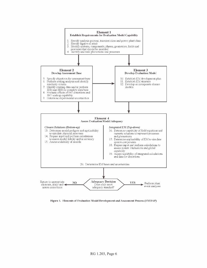
The subjects addressed in References 3 through 6 are complex, and the structures used to addressthose subjects are very detailed. The EMDAP described in this guide is also detailed, so that it can beapplied to the complex events described in SRP Chapter 15. This is particularly true if either the applicationor the proposed methods are new. The complexity of the problem should determine the level of detailneeded to develop and assess an EM. For simpler events, many of the steps in the process may only needto be briefly addressed. Also, if a new EM only involves an incremental change to an existing EM,the process may be shortened as long as the effect of the change is thoroughly addressed. These instancesdescribe a graded approach to the EMDAP, which is discussed in detail in Section 5 of the RegulatoryPosition. Figure 1 augments that discussion by providing an overall diagram of the EMDAP processand the relationships among its elements.
RG 1.203, Page 6
RG 1.203, Page 7
C. REGULATORY POSITION
This section discusses the NRC staff’s regulatory position, which provides guidance concerningmethods for calculating transient and accident behavior. Toward that end, this section describesthe following five related aspects of evaluation model development and assessment:
(1) the four elements and included steps in the EMDAP, based on the first four principles previouslydescribed in the Discussion section and illustrated in Figure 1
(2) the relationship of this process to accepted quality assurance practices, and the incorporationof peer review as described in the fifth principle
(3) items that should be included in EM documentation to be consistent with the sixth principle
(4) unique aspects of general purpose computer programs
(5) a graded approach to application of the EMDAP
Appendix A provides additional information important to ECCS analysis, and Appendix Bpresents an example of the graded application of the EMDAP for different analysis modification scenarios.
1. Evaluation Model Development and Assessment Process (EMDAP)
The basic elements developed to describe an EMDAP directly address the first four principlesdescribed in the Discussion section and illustrated in Figure 1. This regulatory position addressesthe four elements and the adequacy decision shown in Figure 1. Adherence to an EMDAP for newapplications or a completely new EM could involve significant iterations within the process. However,the same process applies even if the new EM is the result of relatively simple modifications to an existing EM. “Feedback” loops are not shown; rather, they are addressed in the adequacy decision described inRegulatory Position 1.5.
1.1 Element 1: Establish Requirements for Evaluation Model Capability
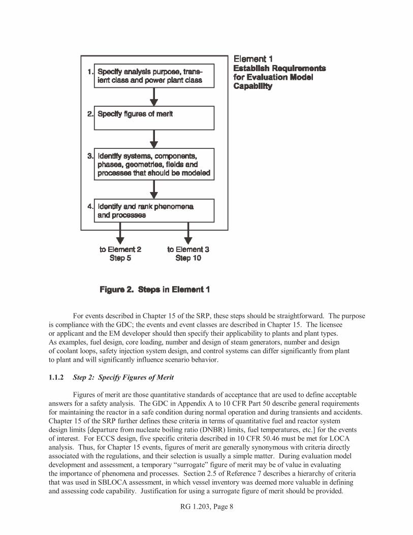
It is very important to determine, at the beginning, the exact application envelope for the EM,and to identify and agree upon the importance of constituent phenomena, processes, and key parameterswithin that envelope. Figure 2 illustrates the steps within this element, as described in the followingsubsections.
1.1.1 Step 1: Specify Analysis Purpose, Transient Class, and Power Plant Class
The first step in establishing EM requirements and capabilities is specifying the analysis purposeand identifying the transient class and plant class to be analyzed. Specifying the purpose is importantbecause any given transient may be analyzed for different reasons. For instance, an SBLOCA may beanalyzed to assess the potential for pressurized thermal shock (PTS) or compliance with10 CFR 50.46. The statement of purpose influences the entire process of development, assessment, and analysis. Evaluation model applicability is scenario-dependent because the dominant processes, safety parameters,and acceptance criteria change from one scenario to another. The transient scenario, therefore, dictatesthe processes that must be addressed. A complete scenario definition is plant-class-specific or sometimeseven plant-specific because the dominant phenomena and their interactions differ in varying degreeswith the reactor design or a plant-specific configuration such as a specific fuel type or core loading.
RG 1.203, Page 8
For events described in Chapter 15 of the SRP, these steps should be straightforward. The purposeis compliance with the GDC; the events and event classes are described in Chapter 15. The licenseeor applicant and the EM developer should then specify their applicability to plants and plant types. As examples, fuel design, core loading, number and design of steam generators, number and designof coolant loops, safety injection system design, and control systems can differ significantly from plantto plant and will significantly influence scenario behavior.
1.1.2 Step 2: Specify Figures of Merit
Figures of merit are those quantitative standards of acceptance that are used to define acceptableanswers for a safety analysis. The GDC in Appendix A to 10 CFR Part 50 describe general requirementsfor maintaining the reactor in a safe condition during normal operation and during transients and accidents. Chapter 15 of the SRP further defines these criteria in terms of quantitative fuel and reactor systemdesign limits [departure from nucleate boiling ratio (DNBR) limits, fuel temperatures, etc.] for the eventsof interest. For ECCS design, five specific criteria described in 10 CFR 50.46 must be met for LOCAanalysis. Thus, for Chapter 15 events, figures of merit are generally synonymous with criteria directlyassociated with the regulations, and their selection is usually a simple matter. During evaluation modeldevelopment and assessment, a temporary “surrogate” figure of merit may be of value in evaluatingthe importance of phenomena and processes. Section 2.5 of Reference 7 describes a hierarchy of criteriathat was used in SBLOCA assessment, in which vessel inventory was deemed more valuable in definingand assessing code capability. Justification for using a surrogate figure of merit should be provided.

RG 1.203, Page 9
In line with the surrogate figure of merit, it is also important to consider other relatedperformance measures in conjunction with the principle objectives. Because compensating errorsin the code can unintentionally lead to correct answers, additional performance measures serve asphysical tracking points and additional proof of accuracy. While the code may calculate the correctpeak cladding temperature (PCT), for example, incorrect or physically impossible parameter valuescould evolve in other areas of the calculation.
1.1.3 Step 3: Identify Systems, Components, Phases, Geometries, Fields, and ProcessesThat Must Be Modeled
The purpose of this step is to identify the EM characteristics. In References 4 and 5, hierarchicalsystem decomposition methods were used to investigate scaling in complex systems. These methods canalso be valuable in identifying EM characteristics. In order from top to bottom, References 4 and 5describe the following ingredients at each hierarchical level:
(1) System: The entire system that must be analyzed for the proposed application.
(2) Subsystems: Major components that must be considered in the analysis. For some applications,these may include the primary system, secondary system, and containment. For other applications,only the primary system would need to be considered.
(3) Modules: Physical components within the subsystem (i.e., reactor vessel, steam generator,pressurizer, piping run, etc.)
(4) Constituents: Chemical form of substance (e.g., water, nitrogen, air, boron, etc.)
(5) Phases: Solid, liquid, or vapor.
(6) Geometrical Configurations (phase topology or flow regime): The geometrical shapedefined for a given transfer process (e.g., pool, drop, bubble, film, etc.)
(7) Fields: The properties that are being transported (i.e., mass, momentum, and energy).
(8) Transport Processes: Mechanisms that determine the transport of and interactions betweenconstituent phases throughout the system.
Ingredients at each hierarchical level can be decomposed into the ingredients at the next level down. In References 4 and 5, this process is described as follows:
(1) Each system can be divided into interacting subsystems.
(2) Each subsystem can be divided into interacting modules.
(3) Each module can be divided into interacting constituents.
(4) Each constituent can be divided into interacting phases.
(5) Each phase can be characterized by one or more geometrical configurations (phase topologyor flow regime).
(6) Each phase can be described by field equations (e.g., conservation equations for mass, energy,and momentum).
(7) The evolution of each field can be affected by several transport processes.
By carefully defining the number and type of each ingredient at each level, the evaluation modeldeveloper should be able to establish the basic characteristics of the EM. An important principle to noteis that if a deficiency exists at a higher level, it is usually not possible to resolve it by fixing ingredientsat lower levels. For relatively simple transients, the decomposition process should also be simple.
RG 1.203, Page 10
1.1.4 Step 4: Identify and Rank Key Phenomena and Processes
Process identification is the last step in the decomposition described above and provides the logicalbeginning to this step. Plant behavior is not equally influenced by all processes and phenomena that occurduring a transient. An optimum analysis reduces candidate phenomena to a manageable set by identifyingand ranking the phenomena with respect to their influence on figures of merit. Each phase of the transientscenario and system components are separately investigated. The processes and phenomena associatedwith each component are examined. Cause and effect are differentiated. After the processes and phenomenahave been identified, their importance should be determined with respect to their effect on the relevantfigures of merit.
The importance determination should also be applied to high-level system processes, which maybe missed if the focus is solely on components. High-level system processes, such as depressurizationand inventory reduction, are often very closely related to figures of merit. Focus on such processescan also help to identify the importance of individual component behaviors.
As noted in Step 2, it may be possible to show that a figure of merit other than the applicableacceptance criterion is more appropriate as a standard for identifying and ranking phenomena. This isacceptable as long as it can be shown that, for all scenarios being considered for the specific rankingand identification activity, the alternative figure of merit is consistent with plant safety.
The principal product of the process outlined above is a phenomena identification and ranking table(PIRT) (see References 3, 6, 7, 9, and 12). Evaluation model development and assessment should bebased on a credible and scrutable PIRT. The PIRT should be used to determine the requirements forphysical model development, scalability, validation, and sensitivities studies. Ultimately, the PIRT is usedto guide any uncertainty analysis or in the assessment of overall EM adequacy. The PIRT is not an endin itself; rather it is a tool to provide guidance for the subsequent steps.
The processes and phenomena that EMs should simulate are found by examining experimental data,experience, and code simulations related to the specific scenario. Independent techniques to accomplishthe ranking include expert opinion, selected calculations, and decision-making methods, such asthe Analytical Hierarchical Process (AHP). Reference 12 provides examples of expert opinionand selected calculations, while Reference 13 provides an example of decision-making methods. Comparing the results of these techniques provides assurance of the accuracy and sufficiency of the process.
The initial phases of the PIRT process described in this step can rely heavily on expert opinion,which can be subjective. Therefore, it is important to validate the PIRT using experimentation and analysis. Although the experience is limited, development of other less-subjective initial importance determinationmethods is encouraged.
Sensitivity studies can help determine the relative influence of phenomena identified early inthe PIRT development and for final validation of the PIRT as the EMDAP is iterated. References 3, 6, 9,11, and 12 provide examples of sensitivity studies used for this purpose.
The identification of processes and phenomena proceeds as follows:
(1) The scenario is divided into operationally characteristic time periods in which the dominantprocesses and phenomena remain essentially constant.
(2) For each time period, processes and phenomena are identified for each component,following a closed circuit throughout the system, to differentiate cause from effect.

RG 1.203, Page 11
(3) Starting with the first time period, the activities continue, component by component, until allpotentially significant processes have been identified.
(4) The procedure is repeated sequentially, from time period to time period, until the end of the scenario.
When the identification has been completed, the ranking process begins. The reason tonumerically rank the processes and phenomena is based on the need to provide a systematic and consistentapproach to all subsequent EMDAP activities.
Sufficient documentation should accompany the PIRT to adequately guide the entire EMDAP. Development and assessment activities may be revisited during the process, including the identificationand ranking. In the end, however, the EM, PIRT, and all documentation should be “frozen” to providethe basis for a proper review. With well-defined ranking of important processes, EM capabilities,and calculated results, further modeling improvements can more easily be prioritized. An important principleis the recognition that the more highly ranked phenomena and processes require greater modeling fidelity. References 6 and 7 describe the role of the PIRT process in experiments, code development, and codeapplications associated with reactor safety analysis.
1.2 Element 2: Develop Assessment Base
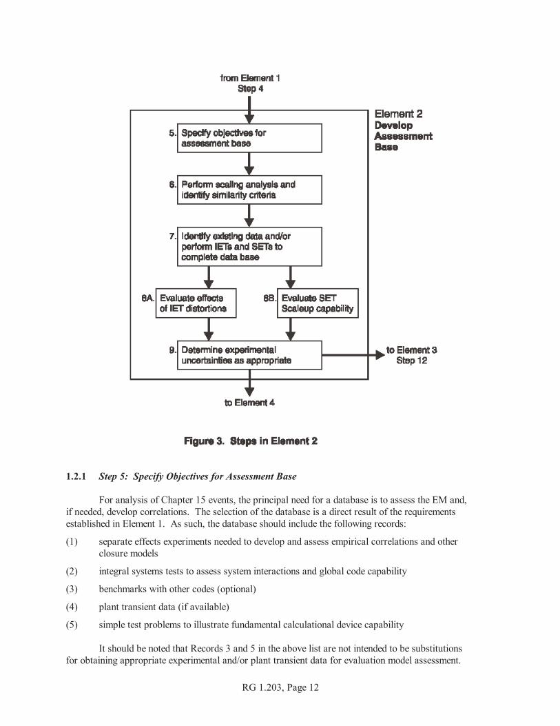
The second component of ISTIR (Refs. 4 and 5) is a scaling methodology that includes acquiringappropriate experimental data relevant to the scenario being considered and ensuring the suitabilityof experimental scaling. References 4 and 5 show the relationship of the severe accident scaling methodology(SASM) component to code development, although that relationship was not emphasized in the SASMdemonstration. For the EMDAP, the purpose is to provide the basis for development and assessmentas previously depicted in Figure 1. Figure 3 shows the steps and their relationships for Element 2. The reader should also note that for simple transients or transients where the scaling issues and assessmentare well-characterized, the implementation of this element should also be simple. The numbering of stepsin this and subsequent elements continues from each previous element.
RG 1.203, Page 12
1.2.1 Step 5: Specify Objectives for Assessment Base
For analysis of Chapter 15 events, the principal need for a database is to assess the EM and,if needed, develop correlations. The selection of the database is a direct result of the requirementsestablished in Element 1. As such, the database should include the following records:
(1) separate effects experiments needed to develop and assess empirical correlations and otherclosure models
(2) integral systems tests to assess system interactions and global code capability
(3) benchmarks with other codes (optional)
(4) plant transient data (if available)
(5) simple test problems to illustrate fundamental calculational device capability
It should be noted that Records 3 and 5 in the above list are not intended to be substitutionsfor obtaining appropriate experimental and/or plant transient data for evaluation model assessment.
RG 1.203, Page 13
1.2.2 Step 6: Perform Scaling Analysis and Identify Similarity Criteria
All experiments are compromises with full-scale plant systems. Even nominally full-scaleexperiments do not include complete similitude. Scaling analyses should be conducted to ensure that the data,and the models based on those data, will be applicable to the full-scale analysis of the plant transient. Scaling compromises identified here should ultimately be addressed in the bias and uncertainty evaluationin Element 4. Scaling analyses are employed to demonstrate the relevancy and sufficiency of the collectiveexperimental database for representing the behavior expected during the postulated transient and to investigatethe scalability of the EM and its component codes for representing the important phenomena. The scopeof these analyses is much broader than for the scalability evaluations described in Element 4 relatingindividual models and correlations or scaling-related findings from the code assessments. Here, the needis to demonstrate that the experimental database is sufficiently diverse that the expected plant-specificresponse is bounded and the EM calculations are comparable to the corresponding tests in non-dimensionalspace. This demonstration allows extending the conclusions related to code capabilities, drawn fromassessments comparing calculated and measured test data (Element 4), to the prediction of plant-specifictransient behavior.
The scaling analyses employ both top-down and bottom-up approaches. The top-down scalingapproach evaluates the global system behavior and systems interactions from integral test facilitiesthat can be shown to represent the plant-specific design under consideration. A top-down scalingmethodology is developed and applied to achieve the following purposes:
(1) Derive the non-dimensional groups governing similitude between facilities.
(2) Show that these groups scale the results among the experimental facilities.
(3) Determine whether the ranges of group values provided by the experiment set encompassthe corresponding plant- and transient-specific values.
The bottom-up scaling analyses address issues raised in the plant- and transient-specific PIRTrelated to localized behavior. These analyses are used to explain differences among tests in differentexperimental facilities and to use these explanations to infer the expected plant behavior and determinewhether the experiments provide adequate plant-specific representation. Section 5.3 of Reference 6describes the application of this scaling process.
In most applications, especially those with a large number of processes and parameters, it is difficult,if not impossible, to design test facilities that preserve total similitude between the experiment and the plant. Therefore, based on the important phenomena and processes identified in Step 4 and the scaling analysisdescribed above, the optimum similarity criteria should be identified, and the associated scaling rationalesdeveloped for selecting existing data or designing and operating experimental facilities.
1.2.3 Step 7: Identify Existing Data and/or Perform Integral Effects Tests (IETs)and Separate Effects Tests (SETs) To Complete the Database
Based on the results of the previous steps in this element, it should be possible to completethe database by selection and experimentation. To complete the assessment matrix, the PIRT developedin Step 4 is used to select experiments and data that best address the important phenomena and components. In selecting experiments, a range of tests should be employed to demonstrate that the calculational deviceor phenomenological model has not been tuned to a single test. A correlation derived from a particulardata set may be identified for inclusion in the EM. In such cases, an effort should be made to obtainadditional data sets that may be used to assess the correlation. Ideally, both the data that will be usedto develop the correlation and the data that will be used to assess the correlation should be identifiedbefore developing the correlation. This would help to ensure that the correlation is not tuned to a particular
RG 1.203, Page 14
data set, and that the data used to assess the correlation have not been deliberately selected to makethe correlation appear to be more accurate than it truly is. The data used for development and assessmentshould cover the full range of conditions for which the correlation will be used. For integral behaviorassessment, counterpart tests (similar scenarios and transient conditions) in different experimentalfacilities at different scales should be selected. Assessments using such tests lead to informationconcerning scale effects on the models used for a particular calculational device.
1.2.4 Step 8: Evaluate Effects of IET Distortions and SET Scaleup Capability
(a) IET Distortions. Distortions in the integral effects test (IET) database may arise from scalingcompromises (missing or atypical phenomena) in sub-scale facilities or atypical initial andboundary conditions in all facilities. The effects of the distortions should be evaluated in thecontext of the experimental objectives determined in Step 5. If the effects are important, a returnto Step 7 is probably needed.
(b) SET Scaleup. As noted in Step 7, correlations should be based on separate effects tests (SETs)at various scales. In the case of poor scaleup capability, it may be necessary to return to Step 6. Appendix C of Reference 3 describes the rationale and techniques associated with evaluatingscaleup capabilities of computer codes and their supporting experimental databases.
1.2.7 Step 9: Determine Experimental Uncertainties as Appropriate
It is important to know the uncertainties in the database. These uncertainties arise frommeasurement errors, experimental distortions, and other aspects of experimentation. If the quantifiedexperimental uncertainties are too large compared to the requirements for evaluation model assessment,the particular data set or correlation should be rejected.
1.3 Element 3: Develop Evaluation Model
As previously discussed, an EM is a collection of calculational devices (codes and procedures)developed and organized to meet the requirements established in Element 1. Figure 4 depicts the stepsfor developing the desired EM.

RG 1.203, Page 15
1.3.1 Step 10: Establish an Evaluation Model Development Plan
Based on the requirements established in Element 1, an EM development plan should be devised.Such a plan should include development standards and procedures that will apply throughoutthe development activity, and should address the following specific areas of focus:
(1) design specifications for the calculational device(2) documentation requirements (see Regulatory Position 3 of this guide)(3) programming standards and procedures(4) transportability requirements(5) quality assurance procedures (see Regulatory Position 2 of this guide)(6) configuration control procedures
1.3.2 Step 11: Establish Evaluation Model Structure
The EM structure includes the structure of the individual component calculational devices,as well as the structure that combines the devices into the overall EM. This structure should be based onthe principles of Element 1 (especially Step 3), as well as the requirements established in Element 1and Step 10. The structure for an individual device or code consists of the following six ingredients:
(1) Systems and components: The EM structure should be able to analyze the behavior of all systemsand components that play a role in the targeted application.
(2) Constituents and phases: The code structure should be able to analyze the behavior of allconstituents and phases relevant to the targeted application.
(3) Field equations: Field equations are solved to determine the transport of the quantities ofinterest (usually mass, energy, and momentum).
RG 1.203, Page 16
(4) Closure relations: Closure relations are correlations and equations that help to model the termsin the field equations by providing code capability to model and scale particular processes.
(5) Numerics: Numerics provide code capability to perform efficient and reliable calculations.
(6) Additional features: These address code capability to model boundary conditions and controlsystems.
Because of the importance of selecting proper closure relationships for the governing equations,these models are treated separately in Step 12. The six ingredients described above should be successfullyintegrated and optimized if a completed code is to meet the objectives determined in Step 10.
The special concerns related to integrating the component calculational devices into a complete EMare frequently referred to collectively as the EM methodology. The way in which the devices are connectedspatially and temporally should be described. How close the coupling needs to be would be determined,in part, by the results of the analysis done in Step 3, but would also be determined by the magnitudeand direction of transfer processes between devices. The hierarchical decomposition described inReferences 4 and 5 would apply to how transfer processes between devices are analyzed. Since mostdevices include user options, all selections made should be justified as appropriate for the EM.
1.3.3 Step 12: Develop or Incorporate Closure Models
Models or closure relationships that describe a specific process are developed using SET data. This includes models that can be used in a standalone mode or correlations that can be incorporated ina calculational device (usually a computer code). On rare occasions, sufficient experimental detailmay be available to develop correlations from IET experiments. The scalability and range ofapplicability of a correlation may not be known (a priori) the first time it is developed or selected for usein this step. An iteration of scaleup evaluation (Step 8) and adequacy assessment (Element 4) may beneeded to ensure correlation applicability. (Note that Figure 1 shows a path from Element 2 to this step,because correlations may be selected from the existing database literature.)
Models developed here are key to successful EM development. The basis, range of applicability,and accuracy of incorporated phenomenological models should be known and traceable. Justificationshould be provided for extension of any models beyond their original bases.
1.4 Element 4: Assess Evaluation Model Adequacy
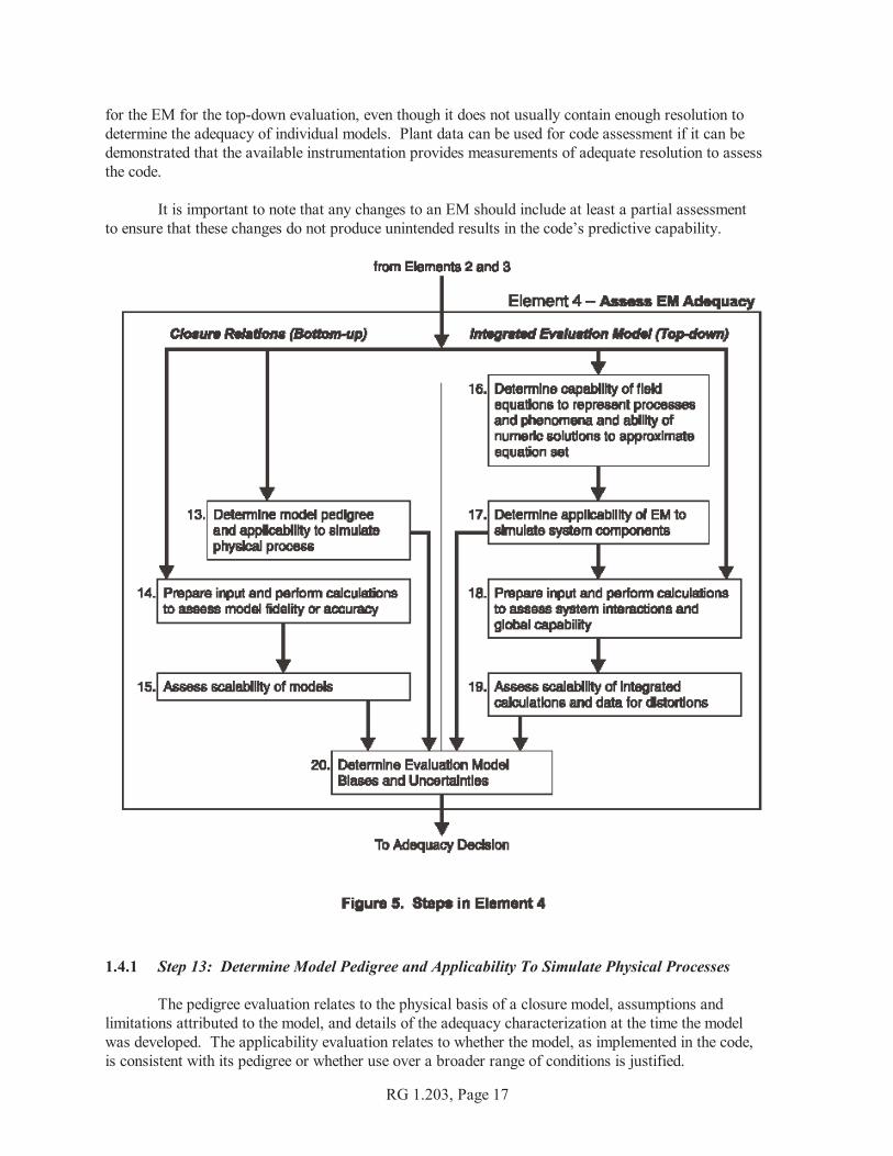
Evaluation model adequacy can be assessed after the previous elements have been establishedand the EM capability has been documented. Figure 5 is a diagram of Element 4.
The EM assessment is divided into two parts as shown in Figure 5. The first part (Steps 13–15)pertains to the bottom-up evaluation of the closure relations for each code. In the first part, importantclosure models and correlations are examined by considering their pedigree, applicability, fidelity toappropriate fundamental or SET data, and scalability. The term bottom-up is used because the reviewfocuses on the fundamental building blocks of the code.
The second part (Steps 16–19) pertains to the top-down evaluations of code-governing equations,numerics, the integrated performance of each code, and the integrated performance of the overall EM. In the second part of the assessment, the EM is evaluated by examining the field equations, numerics,applicability, fidelity to component or integral effects data and scalability. This part of the assessmentis called the top-down review because it focuses on capabilities and performance of the EM. Calculations of actual plant transients or accidents can be useful as confirmatory supporting assessments
RG 1.203, Page 17
for the EM for the top-down evaluation, even though it does not usually contain enough resolution todetermine the adequacy of individual models. Plant data can be used for code assessment if it can bedemonstrated that the available instrumentation provides measurements of adequate resolution to assessthe code.
It is important to note that any changes to an EM should include at least a partial assessmentto ensure that these changes do not produce unintended results in the code’s predictive capability.
1.4.1 Step 13: Determine Model Pedigree and Applicability To Simulate Physical Processes
The pedigree evaluation relates to the physical basis of a closure model, assumptions andlimitations attributed to the model, and details of the adequacy characterization at the time the modelwas developed. The applicability evaluation relates to whether the model, as implemented in the code,is consistent with its pedigree or whether use over a broader range of conditions is justified.
RG 1.203, Page 18
1.4.2 Step 14: Prepare Input and Perform Calculations To Assess Model Fidelity or Accuracy
The fidelity evaluation relates to the existence and completeness of validation efforts (throughcomparison to data), benchmarking efforts (through comparison to other standards, such as a closed-formsolution or results obtained with another code), or some combination of these comparisons.
SET input for component devices used in model assessment (usually computer codes) should beprepared to represent the phenomena and test facility being modeled, as well as the characteristics ofthe nuclear power plant design. In particular, nodalization and option selection should be consistentbetween the experimental facility and similar components in the nuclear power plant. Nodalizationconvergence studies should be performed to the extent practicable in both the test facility and plant models. Some models are essentially lumped parameter models and, in those cases, a nodalization convergencestudy cannot be performed. In such cases, care should be taken to ensure that the model is applicableto both the test facility and the plant. When the calculations of the SETs are completed, the differencesbetween calculated results and experimental data for important phenomena should be quantified for biasand deviation.
1.4.3 Step 15: Assess Scalability of Models
The scalability evaluation is limited to whether the specific model or correlation is appropriatefor application to the configuration and conditions of the plant and transient under evaluation. References 5 and 14–17 document recent approaches to scaling, ranging from theoretical methodsto specific applications that are of particular interest here.
1.4.4 Step 16: Determine Capability of Field Equations To Represent Processes and Phenomenaand the Ability of Numeric Solutions To Approximate Equation Set
The field equation evaluation considers the acceptability of the governing equations in eachcomponent code. The objective of this evaluation is to characterize the relevance of the equationsfor the chosen application. Toward that end, this evaluation should consider the pedigree, key concepts,and processes culminating in the equation set solved by each component code.
The numeric solution evaluation considers convergence, property conservation, and stabilityof code calculations to solve the original equations when applied to the target application. The objectiveof this evaluation is to summarize information regarding the domain of applicability of the numericaltechniques and user options that may impact the accuracy, stability, and convergence features of eachcomponent code.
A complete assessment within this step can only be performed after completing a sufficientfoundation of assessment analyses. Section 3 and Appendix A to Reference 6 provide an examplefor application of this step.
1.4.5 Step 17: Determine Applicability of Evaluation Model To Simulate System Components
This applicability evaluation considers whether the integrated code is capable of modelingthe plant systems and components. Before performing integrated analyses, the various EM options,special models, and inputs should be determined to have the inherent capability to model the majorsystems and subsystems required for the particular application.
RG 1.203, Page 19
1.4.6 Step 18: Prepare Input and Perform Calculations To Assess System Interactionsand Global Capability
This fidelity evaluation considers the comparison of EM-calculated and measured test datafrom component and integral tests and, where possible, plant transient data. For these calculations,the entire EM or its major components should be exercised in comparing data against the integral databaseselected in Element 2.
As in the SET assessments for Step 14, the EM input for IETs should best represent the facilitiesand characteristics of the nuclear power plant design. Nodalization and option selection should also beconsistent between the experiment and nuclear power plant. In addition, nodalization convergencestudies should be performed to the extent practicable in both the test facility and plant models. Somemodels are essentially lumped parameter models and, in such cases, a nodalization convergence studycannot be performed and care must be taken to ensure that the model is applicable to both the test facilityand the plant. Once the IET simulations have been completed, the differences between calculated resultsand experimental data for important processes and phenomena should be quantified for bias and deviation. The ability of the EM to model system interactions should also be evaluated in this step, and plant inputdecks should be prepared for the target applications. Sufficient analyses should be performed to determineparameter ranges expected in the nuclear power plant. These input decks also provide the groundworkfor analyses performed in Step 20. Section 5 of Reference 6 provides a sample application of this step.
1.4.7 Step 19: Assess Scalability of Integrated Calculations and Data for Distortions
This scalability evaluation is limited to whether the assessment calculations and experimentsexhibit otherwise unexplainable differences among facilities, or between calculated and measured datafor the same facility, which may indicate experimental or code scaling distortions.
1.4.8 Step 20: Determine Evaluation Model Biases and Uncertainties
The purpose of the analysis (established in Step 1) and complexity of the transient determinethe substance of this step. For best-estimate LOCA analysis, References 3 and 18 describe the uncertaintydetermination and provide related guidance, augmented by Appendix A to this guide. In these examples,the uncertainty analyses have the ultimate objective of providing a singular statement of uncertainty,with respect to the acceptance criteria set forth in 10 CFR 50.46, when using the best-estimate optionin that rule. This singular uncertainty statement is accomplished when the individual uncertaintycontributions are determined (see Regulatory Guide 1.157, Ref. 18).
Other SRP events do not require a complete uncertainty analysis. However, in most cases,the SRP guidance is to use “suitably conservative” input parameters. This suitability determinationmay involve a limited assessment of biases and uncertainties, and closely relates to the analyses in Step 16because what constitutes “suitably conservative” input depends on the set of field equations chosen forthe EM. Based on the results of Step 4, individual device models can be chosen from those obtainedin Step 9. The individual uncertainty (in terms of range and distribution) of each key contributoris determined from the experimental data (Step 11), input to the nuclear power plant model, and the effecton appropriate figures of merit evaluated by performing separate nuclear power plant calculations. The figures of merit and devices chosen should be consistent. In most cases, this analysis should involvethe entire EM. The last part of this step is to determine whether the degree of overall conservatismor analytical uncertainty is appropriate for the entire EM. This is done in the context of the purposeof the analysis (established in Step 1) and the regulatory requirements.
RG 1.203, Page 20
As an alternative to using “suitably conservative” input parameters, the EM may choose to perform anuncertainty analysis of the safety limit with an evaluation at the nominal technical specificationsand setpoints being considered as the base case. The safety limit can then be analyzed with uncertaintiesin both phenomena and setpoints evaluated in a probabilistic manner similar to the way the 2200 EF limitis evaluated in a best-estimate LOCA analysis, as described in Regulatory Guide 1.157 (Ref. 18). A hybrid methodology (where some parameters are treated in a bounding manner, and other are treatedin a probabilistic manner) may also be acceptable.
1.5 Adequacy Decision
The decision regarding the adequacy of the EM is the culmination of the EMDAP describedin Regulatory Positions 1.1 through 1.4. Throughout the EMDAP, questions concerning the adequacyof the EM should be asked. At the end of the process, the adequacy should be questioned again to ensurethat all the earlier answers are satisfactory and that intervening activities have not invalidated previousacceptable responses. If unacceptable responses indicate significant EM inadequacies, the code deficiencyshould be corrected and the appropriate steps in the EMDAP should be repeated to evaluate the correction. The process continues until the ultimate question regarding EM adequacy is answered in the affirmative. Of course, the documentation described in Regulatory Position 3 should be updated as code improvementsand assessment are accomplished throughout the process. Analysis, assessment, and sensitivity studiescan also lead to reassessment of the phenomena identification and ranking. Therefore, that documentationshould also be revised as appropriate. It is helpful to develop a list of questions to be asked duringthe process and again at the end. To answer these questions, standards should be established by whichthe capabilities of the EM and its composite codes and models can be assessed. Section 2.2.2of Reference 6 provides an example of the development of such standards.
2. Quality Assurance
Much of what is described throughout this regulatory guide relates to good quality assurancepractices. For that reason, it is important to establish appropriate quality assurance protocol, and to do soearly in the development and assessment process. Moreover, the development, assessment, and applicationof an EM are three activities that relate to the requirements of Appendix B to 10 CFR Part 50. Section IIIof that Appendix specifies a key requirement for these activities, in that design control measures mustbe applied to reactor physics, thermal-hydraulic, and accident analyses. Specifically, Section III statesthat “The design control measures shall provide for verifying or checking the adequacy of design, such asby the performance of design reviews, by the use of alternate or simplified calculational methods, or bythe performance of a suitable testing program.” In addition, Section III states that design changes shouldbe subject to appropriate design control measures.
It is important to note that other parts of Appendix B are also relevant. In particular, these includeSection V, which requires documented instructions (e.g., user guidance); Section XVI, corrective actions(e.g., error control, identification, and correction); and Sections VI and XVII, which address documentcontrol and records retention.
To capture the spirit and intent of Appendix B, independent peer review should be performedat key steps in the process, such as at the end of a major pass through an element. For that reason,the NRC staff recommends that a review team should be convened in the early stages of EM development,to review the EM requirements developed in Element 1. Peer review should also be employedduring the later stages for major inquiries associated with the adequacy decision.
RG 1.203, Page 21
In addition to programmers, developers, and end users, the staff further recommends thatthe peer review team should include independent members with recognized expertise in relevant scienceand engineering disciplines, code numerics, and computer programming. Expert review team memberswho were not directly involved in developing and assessing the EM can enhance its robustness, and canbe of value in identifying deficiencies that are common to large system analysis codes.
Throughout the development process, configuration control practices should be adopted to protectprogram integrity and allow traceability of the development of both the code version and the plant inputdeck used to instruct the code in how to represent the facility or nuclear power plant. Configurationcontrol of the code version and plant input deck are separate but related elements of evaluation modeldevelopment and require the same degree of quality assurance. Responsibility for these functions shouldbe clearly established. At the end of the process, only the approved, identified code version and plantinput deck should be used for licensing calculations.
3. Documentation
Proper documentation allows appraisal of the EM application to the postulated scenario. The EM documentation should cover all elements of the EMDAP process, and should includethe following information:
(1) EM requirements(2) EM methodology(3) code description manuals(4) user manuals and user guidelines(5) scaling reports(6) assessment reports(7) uncertainty analysis reports
3.1 Requirements
The requirements determined in Element 1 should be documented so that the EM can be assessedagainst known guidelines. In particular, a documented, current PIRT is important in deciding whethera particular EM feature should be modified before the EM can be applied with confidence.
3.2 Methodology
Methodology documentation should include the interrelationship of all computational devicesused for the plant transient being analyzed, including the description of input and output. This shouldalso include a complete description and specification of those portions of the EM that are not includedin the computer programs, as well as a description of all other information necessary to specifythe calculational procedure. A very useful part of this description would be a diagram to illustratehow the various programs and procedures are related, both in time and in function. This methodologydescription is needed to know exactly how the transient will be analyzed in its entirety.
RG 1.203, Page 22
3.3 Computational Device Description Manuals
A description manual is needed for each computational device that is contained in the EM. There are several important components to the manual. One component is a description of the modelingtheory and associated numerical schemes and solution models, including a description of the architecture,hydrodynamics, heat structure, heat transfer models, trip systems, control systems, reactor kinetics models,and fuel behavior models.
Another component of the documentation is a “models and correlations quality evaluation”(MC/QE) report, which provides a basis for traceability of the models and detailed information regardingthe closure relations. Information on model and correlation sources, databases, accuracy, scale-up capability,and applicability to specific plant and transient conditions should also be documented in the MC/QE report. Thus, the MC/QE report represents a quality evaluation document that provides a blueprint as to what isin the computational device, how it got there, and where it came from. As such, the MC/QE reporthas three objectives:
(1) Provide information regarding the sources and quality of closure relations (that is, modelsand correlations or other criteria used).
(2) Describe how these closure relations are coded in the device, and ensure that the descriptionsin the manual conform to the coding, and that the coding conforms to the source from whichthe closure relations were derived.
(3) Provide a technical rationale and justification for using these closure relations [that is, to confirmthat the dominant parameters (pressure, temperature, etc.) represented by the modelsand correlations reflect the ranges expected in the plant and transient of interest].
Consequently, for models, correlations, and criteria used, the MC/QE report should achievethe following purposes:
(1) Provide information regarding the original source, supporting database, accuracy,and applicability to the plant-specific transient conditions.
(2) Assess the effects of using the models, correlations, and criteria outside the supporting database,and describe and justify the extrapolation method. For certain applications, the MC/QE reportmay recommend using options other than the defaults. In such cases, the report should provideinstructions to ensure that appropriate validation is performed for the nonstandard options.
(3) Describe the implementation in the device (i.e., actual coding structure).
(4) Describe any modifications required to overcome computational difficulties.
(5) Assess the effects caused by implementation (item 3) or modifications (item 4) on the overallapplicability and accuracy of the code.
Reference 19 is an example of MC/QE documents generated to meet the above requirements.

RG 1.203, Page 23
3.4 Users Manual and User Guidelines
The users manual should completely describe how to prepare all required and optional inputs,while the user guidelines should describe recommended practices for preparing all relevant input. To minimize the risk of inappropriate program use, the guidelines should include the followinginformation:
(1) proper use of the program for the particular plant-specific transient or accident being considered
(2) range of applicability for the transient or accident being analyzed
(3) code limitations for such transients and accidents
(4) recommended modeling options for the transient being considered, equipment required, andchoice of nodalization schemes (plant nodalization should be consistent with nodalization usedin assessment cases)
3.5 Scaling Reports
Reports should be provided for all scaling analyses used to support the viability of the experimentaldatabase, scalability of models and correlations, and scalability of the complete EM. Section 5.3of Reference 6 provides an example and references to scaling analyses done to support adequacy evaluations.
3.6 Assessment Reports
Assessment reports are generally of three types:
(1) Developmental assessment(2) Component assessment(3) Integral effects test assessment
Most developmental assessment (DA) reports should comprise a set of code analyses that focuson a limited set of ranked phenomena. That is, the code or other device should analyze experimentsor plant data that demonstrate (in a separate effects manner) the capability to calculate individual phenomenaand processes determined (by the PIRT) to be important for the specific scenario and plant type.
A code or other device may model certain equipment in a special way; assessment calculationsshould be performed for these components.
Integral effects tests (IETs) should show the EM’s integral capability by comparison to relevantintegral effects experiments or plant data. Some IET assessments may be general in nature, but for EMconsideration, the IET assessments should include a variety of scaled facilities applicable to the plantdesign and transient.
For some plants and transients, code-to-code comparisons can be very helpful. In particular,if a new code or device is intended to have a limited application, the results may be compared to calculationsusing a previous code. However, the previous code should be well-assessed to integral or plant datafor the plant type and transient being considered for the new device. Differences in key input (such assystem nodalization) should be explained so that favorable comparisons provide the right answersfor the right reasons. Such benchmark calculations would not replace assessment of the new code.
RG 1.203, Page 24
A significant amount of evaluation model assessment may be performed before selectingthe plant-specific transient to be analyzed. In other cases, the assessment may be done outside the contextof the plant- and transient-specific EM. In still other cases, the assessment may be done by organizationsother than those responsible for the plant-specific analysis. If it is desired to credit these assessmentsto the plant and transient under consideration, great care should be taken to thoroughly evaluateand document the applicability of those assessments to the present case.
To gain confidence in the predictive capability of an EM when applied to a plant-specific event,it is important for assessment reports to achieve the following purposes:(1) Assess calculational device capability and quantify accuracy to calculate various parameters
of interest (in particular, those described in the PIRT).(2) Determine whether the calculated results are attributable to compensating errors by performing
appropriate scaling and sensitivity analyses.(3) Assess whether the calculated results are self-consistent and present a cohesive set of information
that is technically rational and acceptable.(4) Assess whether the timing of events calculated by the EM agrees with the experimental data.(5) Assess the capability of the EM to scale to the prototypical nuclear plant. (Almost without
exception, such assessments also address the experimental database used in developingor validating the EM.)
(6) Explain any unexpected or (at first glance) strange results calculated by the EM or componentdevices. (This is particularly important when experimental measurements are not availableto give credence to the calculated results. In such cases, rational technical explanationsgreatly support credibility and confidence in the EM.)
Whenever the calculated results disagree with experimental data, assessment reports must alsoachieve the following purposes:(7) Identify and explain the cause for the discrepancy; that is, identify and discuss the deficiency
in the device (or, if necessary, discuss the inaccuracy of experimental measurements).(8) Address how important the deficiency is to the overall results (that is, to parameters and issues
of interest).(9) Explain why a deficiency may not have an important effect on a particular scenario.
With respect to a calculational device input model and the related sensitivity studies, assessmentreports must achieve the following additional purposes:(10) Provide a nodalization diagram, along with a discussion of the nodalization rationale.(11) Specify and discuss the boundary and initial conditions, as well as the operational conditions
for the calculations.(12) Present and discuss the results of sensitivity studies (if performed) on closure relations or other
parameters.(13) Discuss modifications to the input model (nodalization, boundary, initial or operational conditions)
resulting from sensitivity studies (if performed).(14) Document the numerical solution convergence studies, including the basis for the time steps used
and the chosen convergence criteria.(15) Provide guidelines for performing similar analyses.
RG 1.203, Page 25
3.7 Uncertainty Analysis Reports
Documentation should be provided for any uncertainty analyses performed as part of Step 20of the EMDAP.
4. General Purpose Computer Programs
Very often, a general purpose transient analysis computer program (such as RELAP5, TRAC,or RETRAN) is developed to analyze a number of different events for a wide variety of plants. Thesecodes can constitute the major portion of an EM for a particular plant and event. Generic reviews areoften performed for these codes to minimize the amount of work required for plant- and event-specificreviews. These reviews, which are limited in terms of the applications and parameter ranges considered,establish the technical foundation for justifying the applicability of the codes in plant- or event-specificanalyses conducted by licensees. A certain amount of generic assessment may be performed for suchcodes as part of the generic code development. Applying portions of the EMDAP process to an existinggeneral purpose transient analysis computer program is useful in determining its suitability for use asthe basis for an EM and can identify deficiencies in models and assessment that should be addressedbefore the code is submitted for NRC review.
The EMDAP starts with identification of the plant, event, and directly related phenomena. When applied to an EM that uses an existing general purpose transient analysis computer program,this process may indicate that the generic assessment does not include all of the appropriate geometry,phenomena, or necessary range of variables to demonstrate code adequacy for some of the proposedplant-specific event analyses. Evidence of this is the fact that safety evaluations for generic code reviewsoften contain a large number of qualifications on use of the code. To avoid such problems, it is importantto identify the intended range of applicability of the generic code, including its models and correlations. The “generic” assessment that accompanies the code must support its intended range of applicability. Use of the EMDAP before submitting the general purpose transient analysis computer program for reviewcan ensure that the code models and assessment support the use of the code over its intended rangeof applicability. Application of the EMDAP should be considered as a prerequisite before submittinga general purpose transient analysis computer program for review as the basis for EMs that may be usedfor a variety of plant and accident types. Evaluation models that use an approved general purposetransient analysis computer program that has been scrutinized or developed using the EMDAP processcan efficiently identify the models and assessment that support the analysis of the specific plantand accident types for which the EM will be used.
5. Graded Approach to Applying the EMDAP Process
Application of the full EMDAP described in this regulatory guide may not be needed for all EMssubmitted for review by the staff. Some EMs submitted for review are relatively minor modificationsto existing EMs. Thus, the scope and depth of applying the development process to the EM can be based ona graded approach. The following four attributes of the EM should be considered when determiningthe extent to which the full model development process may be reduced for a specific application,as described in the following subsections:(1) novelty of the revised EM compared to the currently acceptable model(2) complexity of the event being analyzed(3) degree of conservatism in the EM(4) extent of any plant design or operational changes that would require reanalysis
RG 1.203, Page 26
5.1 Novelty of the Revised EM Compared to the Currently Acceptable Model
The level of effort involved in applying the development and assessment process should becommensurate with the extent of the changes made to an EM. Small changes to a robust, time-tested EMcomponent, such as a change to a simple heat transfer or drag correlation (possibly required by an errorcorrection), may not require full application of the EMDAP to the entire EM. In this case, scaling wouldonly have to be considered within the context of how well the new model scales to full plant analysisif the model is developed from a reduced-scale test program. Consideration would also have to be givento how well the assessment cases for the model represent full-scale plant conditions. Implementationtesting needs to be performed to show that the new model has been correctly implemented. A smallsubset of the entire code assessment matrix may be adequate to test the phenomena that are affectedby the revised model. Another subset of the code test cases may need to be performed to ensure that otherparts of the model are not inadvertently impacted by the changes. The impact of any changes attributableto an error correction would have to be evaluated for the current license analysis of record. A large modelchange may require application of the EMDAP on a much larger scale. Changing from an equilibrium,drift flux model to a two fluid, non-equilibrium model would be an example of a significant changethat would require an extensive development and assessment process for the new EM.
5.2 Complexity of the Event
The level of effort involved in applying the development process should be commensurate withthe complexity of the EM. At first glance, the EMDAP may seem too burdensome to apply to simple events. However, application of the EMDAP to a simple event will automatically result in a simplified process. In simple events, the number of key physical phenomena should also be small, and the code assessmentonly needs to cover the important phenomena even though the underlying general purpose transient analysiscomputer program may have models that cover a much wider range of conditions. An example of thisis the system evaluation of a pressurized-water reactor pump trip analysis in which the important phenomenamay be limited to a few quantities, such as single-phase liquid wall drag and heat transfer, and pump inertia. In this case, very little assessment would need to be performed, and there may be adequate full-scaleplant data for the code assessment so there would be no need for a scaling analysis. The other extremeis an EM for a large-break LOCA, where the physical phenomena and the mathematical models are complexand cover a wide range of conditions. An extensive code development process and assessment would berequired in this case.
5.3 Degree of Conservatism
The intended results of an analysis can be conservative due to a combination of code input and modelingassumptions. The amount of assessment required for a change to an EM may be significantly reducedif the documented degree of conservatism is large or if the new model can be shown to give moreconservative results than the previous model. However, conservatism in just one aspect of the EM;that is, a heat transfer correlation cannot be used to justify conservatism in the EM as a whole, becauseother aspects of the model may be non-conservative and cause the overall model to be non-conservative. The degree of conservatism in the overall EM must be quantified and documented for the particularapplication in order to justify a reduction in assessment requirements using this argument. Showingthe degree of conservatism in an EM for a simple transient may be accomplished by a relatively simpleuncertainty analysis, even if the underlying computer code is a large multipurpose code. The keyto simplifying the uncertainty analysis is identifying the small number of parameters and physicalphenomena that are important in determining the behavior of the accident.

RG 1.203, Page 27
5.4 Extent of Plant Design or Operational Changes That Require Reanalysis
The level of effort required to apply the process should be commensurate with the extent of changesmade to the plant design or operation. Most changes to plant equipment or operations do not causethe plant to operate outside the range of validity of the EM. In such cases, no additional developmentand assessment needs to be performed. However, this may not be the case for all changes. Examplesof changes that may require additional assessment of the EM are fuel bundle design changes (includinggrid spacer and intermediate flow mixer design changes), increases in the peak linear heat generation rate,or operational changes that may cause reliance on a different safety grade trip which requires accurateprediction of a quantity not required in the previous analysis. In such cases, a limited applicationof the EMDAP (similar to that described in Section 5.1) should be sufficient.
RG 1.203, Page 28
D. IMPLEMENTATION
The purpose of this section is to provide information to applicants and licensees regardingthe NRC staff’s plans for using this regulatory guide. No backfitting is intended or approved in connectionwith the issuance of this guide. Licensees and applicants may propose means other than those specifiedby the Regulatory Positions expressed in this guide for meeting applicable regulations. The NRC staffhas approved this guide for use as an acceptable means of complying with the Commission’s regulationsand for evaluating submittals in the following categories:
(1) Construction permit applications that must meet the design-basis description requirementsof 10 CFR 50.34 and the relationship of the design bases to the principal design criteria describedin Appendix A to 10 CFR Part 50. Chapter 15 of the SRP (Ref. 1) describes the transientsand accidents that the NRC staff reviews as part of the application, and the criteria of Appendix Athat specifically apply to each class of transient and accident. Chapter 15 also states thatacceptable EMs should be used to analyze these transients and accidents.
(2) Operating license applications that must meet the design-basis description requirementsof 10 CFR 50.34 and the relationship of the design bases to the principal design criteria describedin Appendix A to 10 CFR Part 50.
(3) New or modified EMs proposed by vendors or operating reactor licensees that, in accordancewith 10 CFR 50.59, require NRC staff review and approval. In such instances, a graded application ofthe principles of this regulatory guide can be undertaken, based on the nature and extentof the new model or proposed changes. When this graded approach is applied in proposingchanges to existing EMs, the principles of this regulatory guide need only apply to the changes. The owner of the model does not need to backfit the entire model to comply with the principlesof this regulatory guide. The question of whether the changes require a licensing amendmentis beyond the scope of this regulatory guide. That question is addressed in 10 CFR 50.59,and its answer has no bearing on the EM development process.
REGULATORY ANALYSIS
Experience with recent model reviews has demonstrated the need for guidance in the areaof transient and accident analysis methods. There is, however, a perception that new costs will be incurredas a result of new “startup” activities brought on by such guidance. After considering the meritsof providing the guidance or taking no action, the staff concludes that guidance in the form of good principlesof transient and accident code development and assessment outweighs the relatively small initial costof startup activities and documentation.
RG 1.203, Page 29
GLOSSARY
These following definitions are provided in the context of this regulatory guide and may not applyto other uses.
AHP Analytical Hierarchical Process: A software-based analytical methodologyused to combine experimental data with expert judgment to efficiently rankthe relative importance of phenomena and processes to the responseof an NPP to an accident or other transient in a consistent and traceablemanner.
AP600 A 600-MWe advanced passive pressurized-water reactor designed byWestinghouse Electric Company.
Bottom-up An approach to a safety-related analysis similar to top-down (see below),but in which the key feature is to treat all phenomena and processes,including those associated with the analysis tools for modeling,as equally important to the facility’s response to an accident or transient. Therefore, the phenomena and processes are quantified in depth.
Calculational Computer codes or other calculational procedures that comprisea device’s evaluation model.
Chapter 15 events In this regulatory guide, Chapter 15 events refer to the transientsand accidents that are defined in Chapter 15 of the SRP (Ref. 1) to beanalyzed to meet the requirements of the General Design Criteria (GDC)of Appendix A to 10 CFR Part 50, except for the fuel assemblymisloading event and all radiological consequence analyses.
CFR Code of Federal Regulations.
Closure relations Equations and correlations required to supplement the field equationsthat are solved to obtain the required results. This includes physicalproperty definitions and correlations of transport phenomena.
Constituents Chemical form of any material being transported (e.g., water, air, boron).
CSAU Code scaling, applicability, and uncertainty: A process to determinethe applicability, scalability, and uncertainty of a computer codein simulating an accident or other transient. A PIRT process is normallyembedded within a CSAU process. See Reference 3.
DA Developmental Assessment: Calculations performed using the entireevaluation model or its individual calculational devices to validateits capability for the target application.
RG 1.203, Page 30
DNBR Departure from nucleate boiling ratio.
EMDAP Evaluation model development and assessment process.
ECCS Emergency core cooling system.
Evaluation model (EM) Calculational framework for evaluating the behavior of the reactor systemduring a postulated Chapter 15 event, which includes one or morecomputer programs and all other information needed for usein the target application.
Fields The properties that are being transported (mass, momentum, energy).
Field equations Equations that are solved to determine the transport of mass, energy,and momentum throughout the system.
Frozen The condition whereby the analytical tools and associated facility inputdecks remain unchanged (and under configuration control) throughouta safety analysis, thereby ensuring traceability of and consistencyin the final results.
GDC General Design Criteria: Design criteria described in Appendix Ato 10 CFR Part 50.
Geometrical configurations The geometrical shape that is defined for a transfer process(e.g., pool, drop, bubble, film).
H2TS Hierarchical two-tiered scaling: Methodology that uses hierarchicalsystems analysis methods to evaluate experimental scaling. Described in References 4 and 5.
IET Integral Effects Test: An experiment in which the primary focus is onthe global system behavior and the interactions between parametersand processes.
ISTIR Integrated Structure for Technical Issue Resolution: Methodologyderived for severe accident issue resolution. Described in References 4and 5.
LBLOCA Large-break loss-of-coolant accident.
LOCA Loss-of-coolant accident.
LWR Light-water reactor.
MC/QE Models and correlations quality evaluation: A report documentingwhat is in a computer code, the sources used to develop the code,and the conditions under which the original source of informationwas developed.
RG 1.203, Page 31
Model [Without “evaluation” modifier] Equation or set of equationsthat represents a particular physical phenomenon within a calculationaldevice.
Modules Physical components within the subsystem (e.g., reactor vessel,steam generator, pressurizer, piping run).
MYISA Maine Yankee Independent Safety Assessment.
NPP Nuclear power plant.
PCT Peak cladding temperature.
Phase State of matter involved in the transport process, usually liquid or gas. A notable exception is heat conduction through solids.
PIRT Phenomena Identification and Ranking Table: May refer to a tableor process, depending on the context. The process relates to determiningthe relative importance of phenomena (or physical processes)to the behavior of an NPP following the initiation of an accidentor other transient. A PIRT table lists the results of applying the process.
Processes Mechanisms that move properties through the system.
QA Quality Assurance.
SASM Severe accident scaling methodology.
SBLOCA Small-break loss-of-coolant accident.
Scalability (scaling) The process in which the results from a subscale facility (relative toan NPP) or the modeling features of a calculational device are evaluated todetermine the degree to which they represent an NPP.
Scenario Description and time sequence of events.
Sensitivity studies The term is generic to several types of analyses; however, the definition ofgreatest interest here relates to those studies associated with the PIRTprocess and used to determine the relative importance of phenomenaor processes. This may also involve analysis of experimental datathat are a source of information used in the PIRT process.
SET Separate Effects Test: An experiment in which the primary focusis on a single physical phenomena or process.
SRP Standard Review Plan: The acceptable plan for NRC reviewers,as defined in NUREG-0800, “Standard Review Plan for the Reviewof Safety Analysis Reports for Nuclear Power Plants.”
System The entire system that must be analyzed for the proposed application.

RG 1.203, Page 32
Systems code The principal computer code of an evaluation model that describesthe transport of mass, momentum, and energy throughout the reactorcoolant systems.
Subsystems The major components that must be considered in the analysis. For someapplications, this would include the primary system, secondary system,and containment. For other applications, only the primary systemwould need to be considered.
Target application The safety analysis for which a specific purpose, transient type, and NPPtype have been specified.
Top-down The approach to a safety-related analysis in which one sequentiallydetermines (1) the exact objective of the analysis (regulatory action,licensing action, desired product, etc.), (2) the analysis envelope(facility or NPP, transients, analysis codes, facility-imposed geometricand operational boundary conditions, etc.), (3) all plausible phenomenaor processes that have some influence on the facility or plant behavior,(4) a PIRT process, (5) applicability and scalability of the analysis tools,and (6) the influence of various uncertainties embedded in the analysison the end product. A key feature of the top-down approach is to addressthose parts of the safety analysis associated with items 5 and 6in a graduated manner based on the relative importance determinedin item 4. Items 1 through 4 are independent of the analysis tools. Items 5 and 6 are dependent on the chosen analysis tools.
Uncertainty There are three separate but related definitions of primary interest: (1) the inaccuracy in experimentally derived data typically generatedby the inaccuracy of measurement systems, (2) the inaccuracyof calculating primary safety criteria or related figures of merittypically originating in the experimental data or assumptionsused to develop the analytical tools, or (3) the analytical inaccuraciesrelated to approximations and uncertainties.

2 Electronic copies are posted on the NRC’s public Web site, http://www.nrc.gov, through Rulemaking, and from theNRC’s Reproduction and Distribution Services Section, Public Document Room, and Public Electronic ReadingRoom. See footnotes below.
3 Single copies of regulatory guides, both active and draft, and draft NUREG documents may be obtained free of chargeby writing the Reproduction and Distribution Services Section, OCIO, USNRC, Washington, DC 20555-0001, or byfax to (301)415-2289, or by email to [email protected]. Active guides may also be purchased from theNational Technical Information Service (NTIS)on a standing order basis. Details on this service may be obtained bycontacting NTIS at 5285 Port Royal Road, Springfield, Virginia 22161, online at http://www.ntis.gov, or by telephoneat (703) 487-4650. Copies are also available for inspection or copying for a fee from the NRC’s Public DocumentRoom (PDR), which is located at 11555 Rockville Pike, Rockville, Maryland; the PDR’s mailing address is USNRCPDR, Washington, DC 20555-0001. The PDR can also be reached by telephone at (301) 415-4737 or (800) 397-4205,by fax at (301) 415-3548, and by email to [email protected]. Copies of certain guides and many other NRC documentsare available electronically through the Public Electronic Reading Room on the NRC’s public Web site,http://www.nrc.gov, and through the NRC’s Agencywide Documents Access and Management System (ADAMS)at the same Web site.
4 Copies are available at current rates from the U.S. Government Printing Office, P.O. Box 37082, Washington, DC20402-9328 [telephone (202) 512-1800], or from the National Technical Information Service (NTIS), 5285 Port RoyalRoad, Springfield, Virginia 22161 [http://www.ntis.gov, telephone (703) 487-4650]. Copies are available forinspection or copying for a fee from the NRC’s Public Document Room (PDR), which is located at 11555 RockvillePike, Rockville, Maryland; the PDR’s mailing address is USNRC PDR, Washington, DC 20555-0001. The PDR canalso be reached by telephone at (301) 415-4737 or (800) 397-4205, by fax at (301) 415-3548, and by emailto [email protected].
5 Nuclear Engineering and Design is available for electronic download (by free subscription) through Science Direct,a service of the Reed Elsevier Group, athttp://www.sciencedirect.com/science?_ob=JournalURL&_cdi=5756&_auth=y&_acct=C000050221&_version=1&_urlVersion=0&_userid=10&md5=5bc1bb0de40acc1a7b0e4129b21d809f.
RG 1.203, Page 33
REFERENCES
(1) Draft Section 15.0.2, “Review of Analytical Computer Codes,” of NUREG-0800, “StandardReview Plan for the Review of Safety Analysis Reports for Nuclear Power Plants,” USNRC,updated by section, December 2000.2
(2) Regulatory Guide 1.70, “Standard Format and Content of Safety Analysis Reports for NuclearPower Plants (LWR Edition),” Revision 3, USNRC, November 1978.3
(3) B. Boyack et al., “Quantifying Reactor Safety Margins, Application of Code, Scaling,Applicability, and Uncertainty Evaluation Methodology to a Large Break, Loss-of- CoolantAccident,” NUREG/CR-5249, USNRC, December 1989.4
(4) B. Boyack et al., “An Integrated Structure and Scaling Methodology for Severe AccidentTechnical Issue Resolution,” Draft NUREG/CR-5809, USNRC, November 1991.2
(5) N. Zuber et al., “An Integrated Structure and Scaling Methodology for Severe Accident TechnicalIssue Resolution: Development of Methodology,” Nuclear Engineering and Design, 186(pp. 1–21), 1998.5
6 Electronic copies are available through the Public Electronic Reading Room on the NRC’s public Web site,http://www.nrc.gov, and through the NRC’s Agencywide Documents Access and Management System (ADAMS)under Accession #ML003769921.
7 Electronic copies are available through the Public Electronic Reading Room on the NRC’s public Web site,http://www.nrc.gov, and through the NRC’s Agencywide Documents Access and Management System (ADAMS)under Accession #ML003769914.
8 Electronic copies are available through the Public Electronic Reading Room on the NRC’s public Web site,http://www.nrc.gov, and through the NRC’s Agencywide Documents Access and Management System (ADAMS)under Accession #ML003769902.
RG 1.203, Page 34
(6) C.D. Fletcher et al., “Adequacy Evaluation of RELAP5/MOD3, Version 3.2.1.2 for SimulatingAP600 Small Break Loss-of-Coolant Accidents,” INEL-96/0400 (nonproprietary version),April 1997.6
(7) G.E. Wilson and B.E. Boyack, “The Role of the PIRT Process in Experiments, Code Developmentand Code Applications Associated with Reactor Safety Analysis,” Nuclear Engineeringand Design, 186 (pp. 23–37), 1998.4
(8) H. Holmstrom et al., “Status of Code Uncertainty Evaluation Methodologies,” in Proceedingsof the International Conference on New Trends in Nuclear System Thermohydraulics,Dipartimento di Costruzioni Meccaniche Nucleari, Pisa, Italy, 1994.7
(9) M.G. Ortiz and L.S. Ghan, “Uncertainty Analysis of Minimum Vessel Liquid Inventory Duringa Small-Break LOCA in a Babcock and Wilcox Plant,” NUREG/CR-5818, USNRC,December 1992.3
(10) W. Wulff et al., “Uncertainty Analysis of Suppression Pool Heating During an ATWSin a BWR-5 Plant,” NUREG/CR-6200, USNRC, March 1994.3
(11) G.E. Wilson et al., “Phenomena-Based Thermal Hydraulic Modeling Requirements for SystemsAnalysis of a Modular High Temperature Gas-Cooled Reactor,” Nuclear Engineering andDesign, 136 (pp. 319–333), 1992.4
(12) R.A. Shaw et al., “Development of a Phenomena Identification and Ranking Table (PIRT) forThermal-Hydraulic Phenomena During a PWR Large-Break LOCA,” NUREG/CR-5074,USNRC, August 1988.3
(13) J.C. Watkins and L.S. Ghan, “AHP Version 5.1, Users Manual,” EGG-ERTP-10585,Idaho National Engineering Laboratory, October 1992.8
(14) J. Reyes and L. Hochreiter, “Scaling Analysis for the OSU AP600 Test Facility (APEX),”Nuclear Engineering and Design, 186 (pp. 53–109), November 1, 1998.4
(15) S. Banerjee et al., “Scaling in the Safety of Next Generation Reactors,” Nuclear Engineeringand Design, 186 (pp. 111–133), November 1, 1998.4
(16) V. Ransom, W. Wang, M. Ishii, “Use of an Ideal Scaled Model for Scaling Evaluation,”Nuclear Engineering and Design, 186 (pp. 135–148), November 1, 1998.4

RG 1.203, Page 35
(17) M. Ishii et al., “The Three-Level Scaling Approach with Application to the Purdue UniversityMulti-Dimensional Integral Test Assembly (PUMA),” Nuclear Engineering and Design,186 (pp. 177–211), November 1, 1998.4
(18) Regulatory Guide 1.157, “Best-Estimate Calculations of Emergency Core Cooling SystemPerformance,” USNRC, May 1989.2
(19) “RELAP5/MOD3 Code Manual, Models and Correlations,” NUREG/CR-5535, Volume 4,USNRC, August 1995.3
Appendix A to RG 1.203, Page A-1
APPENDIX A
ADDITIONAL CONSIDERATIONS IN THE USE OF THIS REGULATORY GUIDE
FOR ECCS ANALYSIS
A.1 Background
As it existed prior to September 1988, 10 CFR 50.46 provided the requirements for domesticlicensing of production and utilization facilities using conservative analysis methods. The acceptancecriteria for peak clad temperature, cladding oxidation, hydrogen generation, and long-term decay heatremoval were specified in 10 CFR 50.46(b), while Appendix K to 10 CFR Part 50 provided specificrequirements related to ECCS evaluation models. The requirements of 10 CFR 50.46 were in addition tothe requirements of General Design Criterion (GDC) 35 in Appendix A to 10 CFR Part 50, which statedrequirements for electric power and equipment redundancy for ECCS systems. In addition, Section 15.6.5of NUREG-0800, the NRC’s Standard Review Plan, describes for reviewers the scope of review,acceptance criteria, review procedures, and findings relevant to ECCS analyses submitted by licensees,while Section 15.0.2 of NUREG-0800 is the companion SRP section to this regulatory guide.
In September 1988, the NRC amended the requirements of 10 CFR 50.46 and Appendix K so thatthe regulations reflected the improved understanding of ECCS performance during reactor transients,which was obtained through extensive research performed since the NRC published the originalrequirements in January 1974. Examples of that body of research can be found in Reference A-1. The NRC subsequently provided further guidance to licensees or applicants in May 1989 by publishingRegulatory Guide 1.157, “Best-Estimate Calculations of Emergency Core Cooling System Performance.” The amendment to 10 CFR Part 50 and Regulatory Guide 1.157 now permit licensees or applicants to useeither the conservative analysis methods defined in Appendix K or a realistic EM (commonly referred toas best-estimate plus uncertainty analysis methods). That is, the uncertainty in the best-estimate analysismust be quantified and considered when comparing the results of the calculations with the applicable limitsin 10 CFR 50.46(b) so that there is a high probability that the criteria will not be exceeded. It shouldbe noted, however, that the acceptance criteria for peak cladding temperature, cladding oxidation,hydrogen generation, and long-term decay heat removal did not change with the September 1988amendment.
A.2 Need for Regulatory Guidance Update for ECCS Analysis
The regulatory structure described above was strongly founded on the supporting workdocumented in Reference A-2. Therefore, it is important to update the regulatory structure to reflectthe past 11 years of advancement in best-estimate plus uncertainty analysis methods. Examplesof the extension of evolving best-estimate plus uncertainty analysis methods to both the old and newadvanced reactor designs can be found in References A-3 through A-9 of this appendix.
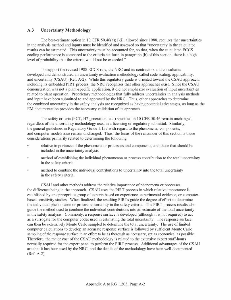
Appendix A to RG 1.203, Page A-2
A.3 Uncertainty Methodology
The best-estimate option in 10 CFR 50.46(a)(1)(i), allowed since 1988, requires that uncertaintiesin the analysis method and inputs must be identified and assessed so that “uncertainty in the calculatedresults can be estimated. This uncertainty must be accounted for, so that, when the calculated ECCScooling performance is compared to the criteria set forth in paragraph (b) of this section, there is a highlevel of probability that the criteria would not be exceeded.”
To support the revised 1988 ECCS rule, the NRC and its contractors and consultantsdeveloped and demonstrated an uncertainty evaluation methodology called code scaling, applicability,and uncertainty (CSAU) (Ref. A-2). While this regulatory guide is oriented toward the CSAU approach,including its embedded PIRT process, the NRC recognizes that other approaches exist. Since the CSAUdemonstration was not a plant-specific application, it did not emphasize evaluation of input uncertaintiesrelated to plant operation. Proprietary methodologies that fully address uncertainties in analysis methodsand input have been submitted to and approved by the NRC. Thus, other approaches to determinethe combined uncertainty in the safety analysis are recognized as having potential advantages, as long as theEM documentation provides the necessary validation of its approach.
The safety criteria (PCT, H2 generation, etc.) specified in 10 CFR 50.46 remain unchanged,regardless of the uncertainty methodology used in a licensing or regulatory submittal. Similarly,the general guidelines in Regulatory Guide 1.157 with regard to the phenomena, components,and computer models also remain unchanged. Thus, the focus of the remainder of this section is thoseconsiderations primarily related to determining the following:
• relative importance of the phenomena or processes and components, and those that should beincluded in the uncertainty analysis
• method of establishing the individual phenomenon or process contribution to the total uncertaintyin the safety criteria
• method to combine the individual contributions to uncertainty into the total uncertaintyin the safety criteria.
CSAU and other methods address the relative importance of phenomena or processes,the difference being in the approach. CSAU uses the PIRT process in which relative importance isestablished by an appropriate group of experts based on experience, experimental evidence, or computer-based sensitivity studies. When finalized, the resulting PIRTs guide the degree of effort to determinethe individual phenomenon or process uncertainty in the safety criteria. The PIRT process results alsoguide the method used to combine the individual contributions into an estimate of the total uncertaintyin the safety analysis. Commonly, a response surface is developed (although it is not required) to actas a surrogate for the computer codes used in estimating the total uncertainty. The response surfacecan then be extensively Monte Carlo sampled to determine the total uncertainty. The use of limitedcomputer calculations to develop an accurate response surface is followed by sufficient Monte Carlosampling of the response surface in an effort to be as thorough as necessary, yet as economical as possible. Therefore, the major cost of the CSAU methodology is related to the extensive expert staff-hoursnormally required for the expert panel to perform the PIRT process. Additional advantages of the CSAUare that it has been used by the NRC, and the details of the methodology have been well-documented(Ref. A-2).

Appendix A to RG 1.203, Page A-3
A potential disadvantage relates to the dependency of the number of computer simulationson the number of phenomena or processes determined in the PIRT that may be needed to estimatethe total uncertainty. That is, at least two “single parameter change” runs must be made for each requiredphenomenon or process. In addition, cross-product runs must be made when several of the phenomenaor processes have significant covariance. The cross-product runs may involve change runs of two, three,or four parameters to adequately determine the effect of nonindependent phenomena or processes.
Methods other than the CSAU methodology may also be used for uncertainty analysis. Examples of other uncertainty methodologies that might be used are described in Reference A-7. Obviously, such submittals would require validation of the methodology (including any statisticalassumptions used in the methodology) to show that it is applicable for determining the uncertaintyof the parameter of interest.
An uncertainty methodology is not required for the original conservative Appendix K optionin 10 CFR 50.46. Rather, the features required by Appendix K provide sufficient conservatismwithout the need for an uncertainty analysis. It should be noted that Section II.4 of Appendix Krequires that “To the extent practicable, predictions of the EM, or portions thereof, shall be comparedwith applicable experimental information.”
Thus, Appendix K requires comparisons to data similar to those required for the best-estimateoption, but without the need for an uncertainty analysis. However, poor comparisons with applicable datamay prevent NRC acceptance of the Appendix K model.
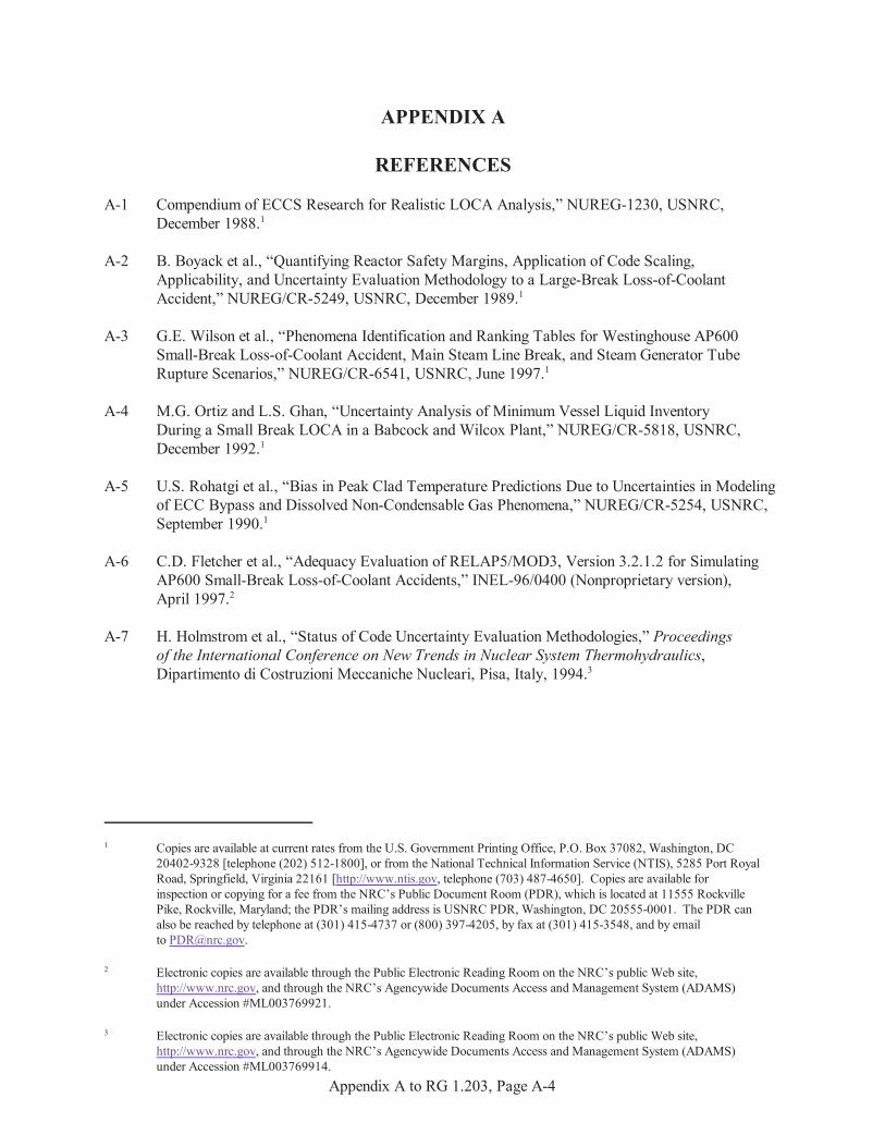
1 Copies are available at current rates from the U.S. Government Printing Office, P.O. Box 37082, Washington, DC20402-9328 [telephone (202) 512-1800], or from the National Technical Information Service (NTIS), 5285 Port RoyalRoad, Springfield, Virginia 22161 [http://www.ntis.gov, telephone (703) 487-4650]. Copies are available forinspection or copying for a fee from the NRC’s Public Document Room (PDR), which is located at 11555 RockvillePike, Rockville, Maryland; the PDR’s mailing address is USNRC PDR, Washington, DC 20555-0001. The PDR canalso be reached by telephone at (301) 415-4737 or (800) 397-4205, by fax at (301) 415-3548, and by emailto [email protected].
2 Electronic copies are available through the Public Electronic Reading Room on the NRC’s public Web site,http://www.nrc.gov, and through the NRC’s Agencywide Documents Access and Management System (ADAMS)under Accession #ML003769921.
3 Electronic copies are available through the Public Electronic Reading Room on the NRC’s public Web site,http://www.nrc.gov, and through the NRC’s Agencywide Documents Access and Management System (ADAMS)under Accession #ML003769914.
Appendix A to RG 1.203, Page A-4
APPENDIX A
REFERENCES
A-1 Compendium of ECCS Research for Realistic LOCA Analysis,” NUREG-1230, USNRC,December 1988.1
A-2 B. Boyack et al., “Quantifying Reactor Safety Margins, Application of Code Scaling,Applicability, and Uncertainty Evaluation Methodology to a Large-Break Loss-of-CoolantAccident,” NUREG/CR-5249, USNRC, December 1989.1
A-3 G.E. Wilson et al., “Phenomena Identification and Ranking Tables for Westinghouse AP600Small-Break Loss-of-Coolant Accident, Main Steam Line Break, and Steam Generator TubeRupture Scenarios,” NUREG/CR-6541, USNRC, June 1997.1
A-4 M.G. Ortiz and L.S. Ghan, “Uncertainty Analysis of Minimum Vessel Liquid InventoryDuring a Small Break LOCA in a Babcock and Wilcox Plant,” NUREG/CR-5818, USNRC,December 1992.1
A-5 U.S. Rohatgi et al., “Bias in Peak Clad Temperature Predictions Due to Uncertainties in Modelingof ECC Bypass and Dissolved Non-Condensable Gas Phenomena,” NUREG/CR-5254, USNRC,September 1990.1
A-6 C.D. Fletcher et al., “Adequacy Evaluation of RELAP5/MOD3, Version 3.2.1.2 for SimulatingAP600 Small-Break Loss-of-Coolant Accidents,” INEL-96/0400 (Nonproprietary version),April 1997.2
A-7 H. Holmstrom et al., “Status of Code Uncertainty Evaluation Methodologies,” Proceedingsof the International Conference on New Trends in Nuclear System Thermohydraulics,Dipartimento di Costruzioni Meccaniche Nucleari, Pisa, Italy, 1994.3

4 Nuclear Engineering and Design is available for electronic download (by free subscription) through Science Direct,a service of the Reed Elsevier Group, athttp://www.sciencedirect.com/science?_ob=JournalURL&_cdi=5756&_auth=y&_acct=C000050221&_version=1&_urlVersion=0&_userid=10&md5=5bc1bb0de40acc1a7b0e4129b21d809f.
Appendix A to RG 1.203, Page A-5
A-8 G.E. Wilson and B.E. Boyack, “The Role of the PIRT Process in Experiments, Code Developmentand Code Applications Associated with Reactor Safety Analysis,” Nuclear Engineeringand Design, 186 (pp. 23–37), 1998.4
A-9 “RELAP5/MOD3 Code Manual, Models and Correlations,” NUREG/CR-5535, Volume 4,USNRC, August 1995.1
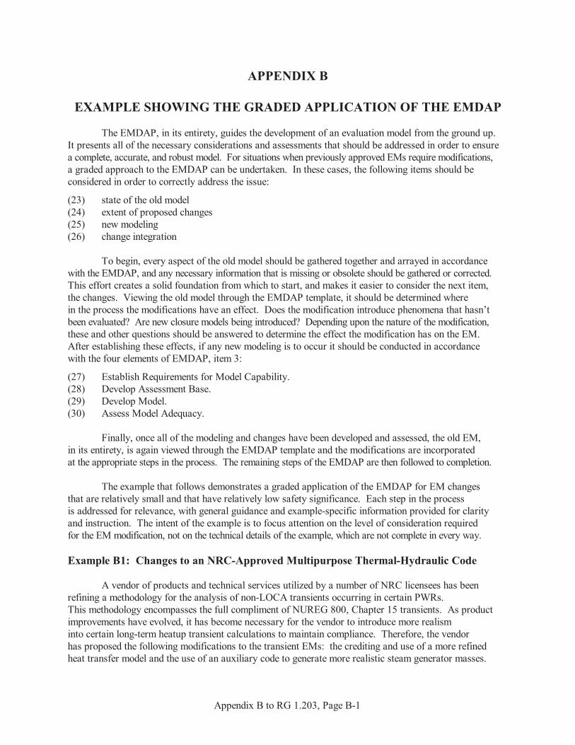
Appendix B to RG 1.203, Page B-1
APPENDIX B
EXAMPLE SHOWING THE GRADED APPLICATION OF THE EMDAP
The EMDAP, in its entirety, guides the development of an evaluation model from the ground up. It presents all of the necessary considerations and assessments that should be addressed in order to ensurea complete, accurate, and robust model. For situations when previously approved EMs require modifications,a graded approach to the EMDAP can be undertaken. In these cases, the following items should beconsidered in order to correctly address the issue:
(23) state of the old model(24) extent of proposed changes(25) new modeling(26) change integration
To begin, every aspect of the old model should be gathered together and arrayed in accordancewith the EMDAP, and any necessary information that is missing or obsolete should be gathered or corrected. This effort creates a solid foundation from which to start, and makes it easier to consider the next item,the changes. Viewing the old model through the EMDAP template, it should be determined wherein the process the modifications have an effect. Does the modification introduce phenomena that hasn’tbeen evaluated? Are new closure models being introduced? Depending upon the nature of the modification,these and other questions should be answered to determine the effect the modification has on the EM. After establishing these effects, if any new modeling is to occur it should be conducted in accordancewith the four elements of EMDAP, item 3:
(27) Establish Requirements for Model Capability.(28) Develop Assessment Base.(29) Develop Model.(30) Assess Model Adequacy.
Finally, once all of the modeling and changes have been developed and assessed, the old EM,in its entirety, is again viewed through the EMDAP template and the modifications are incorporatedat the appropriate steps in the process. The remaining steps of the EMDAP are then followed to completion.
The example that follows demonstrates a graded application of the EMDAP for EM changesthat are relatively small and that have relatively low safety significance. Each step in the processis addressed for relevance, with general guidance and example-specific information provided for clarityand instruction. The intent of the example is to focus attention on the level of consideration requiredfor the EM modification, not on the technical details of the example, which are not complete in every way.
Example B1: Changes to an NRC-Approved Multipurpose Thermal-Hydraulic Code
A vendor of products and technical services utilized by a number of NRC licensees has beenrefining a methodology for the analysis of non-LOCA transients occurring in certain PWRs. This methodology encompasses the full compliment of NUREG 800, Chapter 15 transients. As productimprovements have evolved, it has become necessary for the vendor to introduce more realisminto certain long-term heatup transient calculations to maintain compliance. Therefore, the vendorhas proposed the following modifications to the transient EMs: the crediting and use of a more refinedheat transfer model and the use of an auxiliary code to generate more realistic steam generator masses.
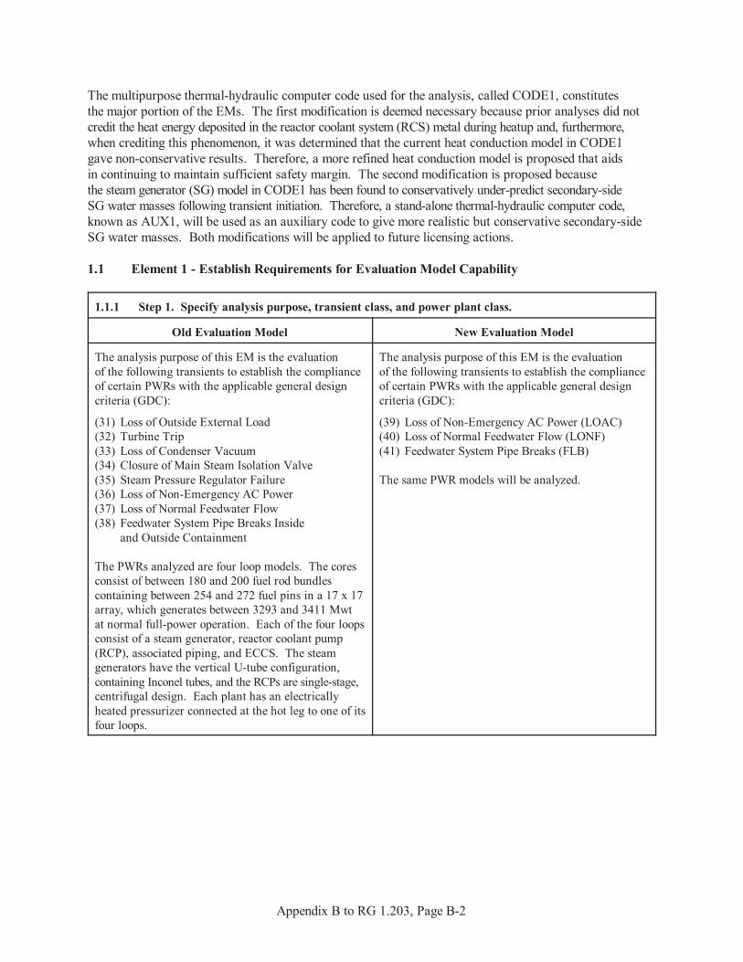
Appendix B to RG 1.203, Page B-2
The multipurpose thermal-hydraulic computer code used for the analysis, called CODE1, constitutesthe major portion of the EMs. The first modification is deemed necessary because prior analyses did notcredit the heat energy deposited in the reactor coolant system (RCS) metal during heatup and, furthermore,when crediting this phenomenon, it was determined that the current heat conduction model in CODE1gave non-conservative results. Therefore, a more refined heat conduction model is proposed that aidsin continuing to maintain sufficient safety margin. The second modification is proposed becausethe steam generator (SG) model in CODE1 has been found to conservatively under-predict secondary-sideSG water masses following transient initiation. Therefore, a stand-alone thermal-hydraulic computer code,known as AUX1, will be used as an auxiliary code to give more realistic but conservative secondary-sideSG water masses. Both modifications will be applied to future licensing actions.
1.1 Element 1 - Establish Requirements for Evaluation Model Capability
1.1.1 Step 1. Specify analysis purpose, transient class, and power plant class.
Old Evaluation Model New Evaluation Model
The analysis purpose of this EM is the evaluationof the following transients to establish the complianceof certain PWRs with the applicable general designcriteria (GDC):
(31) Loss of Outside External Load(32) Turbine Trip(33) Loss of Condenser Vacuum(34) Closure of Main Steam Isolation Valve(35) Steam Pressure Regulator Failure(36) Loss of Non-Emergency AC Power (37) Loss of Normal Feedwater Flow(38) Feedwater System Pipe Breaks Inside
and Outside Containment
The PWRs analyzed are four loop models. The coresconsist of between 180 and 200 fuel rod bundlescontaining between 254 and 272 fuel pins in a 17 x 17array, which generates between 3293 and 3411 Mwtat normal full-power operation. Each of the four loopsconsist of a steam generator, reactor coolant pump(RCP), associated piping, and ECCS. The steamgenerators have the vertical U-tube configuration,containing Inconel tubes, and the RCPs are single-stage,centrifugal design. Each plant has an electricallyheated pressurizer connected at the hot leg to one of itsfour loops.
The analysis purpose of this EM is the evaluationof the following transients to establish the complianceof certain PWRs with the applicable general designcriteria (GDC):
(39) Loss of Non-Emergency AC Power (LOAC)(40) Loss of Normal Feedwater Flow (LONF)(41) Feedwater System Pipe Breaks (FLB)
The same PWR models will be analyzed.
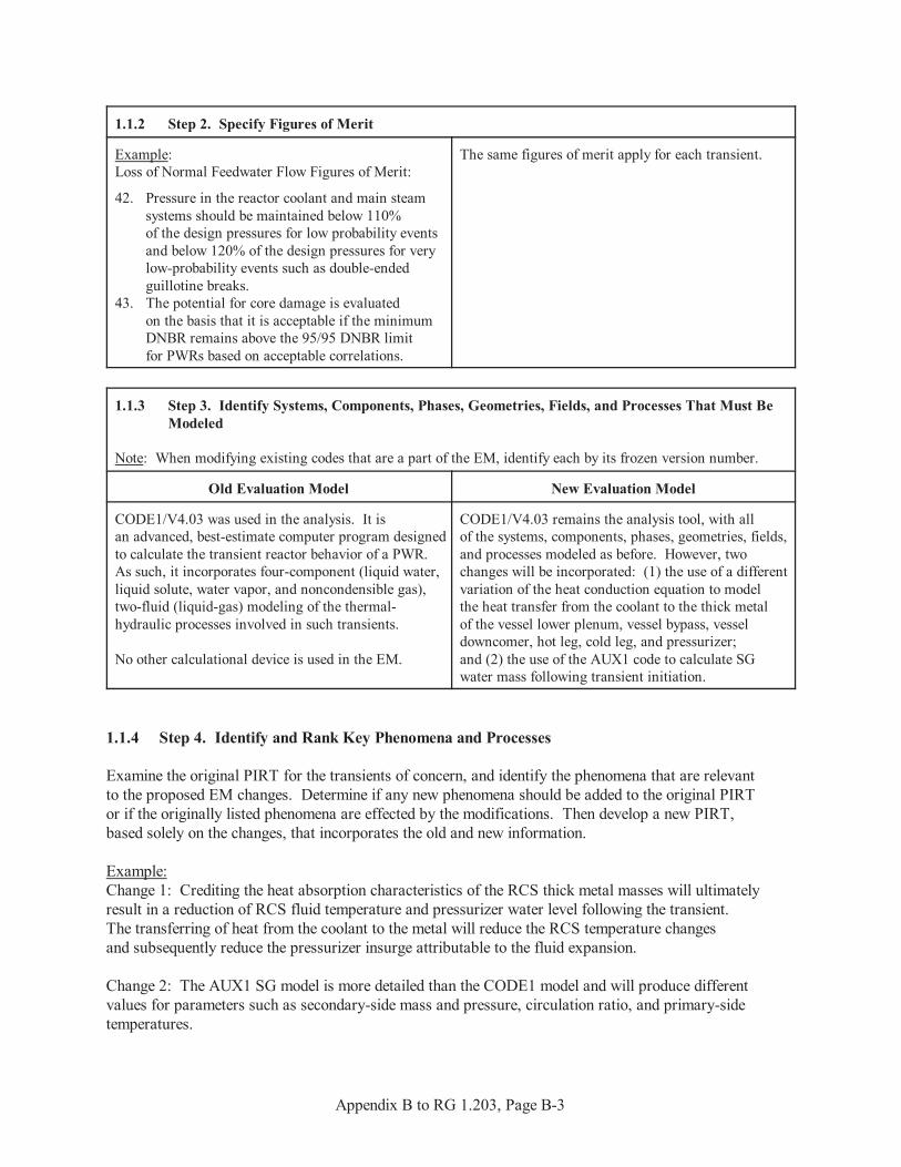
Appendix B to RG 1.203, Page B-3
1.1.2 Step 2. Specify Figures of Merit
Example:Loss of Normal Feedwater Flow Figures of Merit:
42. Pressure in the reactor coolant and main steamsystems should be maintained below 110%of the design pressures for low probability eventsand below 120% of the design pressures for verylow-probability events such as double-endedguillotine breaks.
43. The potential for core damage is evaluatedon the basis that it is acceptable if the minimumDNBR remains above the 95/95 DNBR limitfor PWRs based on acceptable correlations.
The same figures of merit apply for each transient.
1.1.3 Step 3. Identify Systems, Components, Phases, Geometries, Fields, and Processes That Must BeModeled
Note: When modifying existing codes that are a part of the EM, identify each by its frozen version number.
Old Evaluation Model New Evaluation Model
CODE1/V4.03 was used in the analysis. It isan advanced, best-estimate computer program designedto calculate the transient reactor behavior of a PWR. As such, it incorporates four-component (liquid water,liquid solute, water vapor, and noncondensible gas),two-fluid (liquid-gas) modeling of the thermal-hydraulic processes involved in such transients.
No other calculational device is used in the EM.
CODE1/V4.03 remains the analysis tool, with allof the systems, components, phases, geometries, fields,and processes modeled as before. However, twochanges will be incorporated: (1) the use of a differentvariation of the heat conduction equation to modelthe heat transfer from the coolant to the thick metalof the vessel lower plenum, vessel bypass, vesseldowncomer, hot leg, cold leg, and pressurizer;and (2) the use of the AUX1 code to calculate SGwater mass following transient initiation.
1.1.4 Step 4. Identify and Rank Key Phenomena and Processes
Examine the original PIRT for the transients of concern, and identify the phenomena that are relevantto the proposed EM changes. Determine if any new phenomena should be added to the original PIRTor if the originally listed phenomena are effected by the modifications. Then develop a new PIRT,based solely on the changes, that incorporates the old and new information.
Example:Change 1: Crediting the heat absorption characteristics of the RCS thick metal masses will ultimatelyresult in a reduction of RCS fluid temperature and pressurizer water level following the transient. The transferring of heat from the coolant to the metal will reduce the RCS temperature changesand subsequently reduce the pressurizer insurge attributable to the fluid expansion.
Change 2: The AUX1 SG model is more detailed than the CODE1 model and will produce differentvalues for parameters such as secondary-side mass and pressure, circulation ratio, and primary-sidetemperatures.
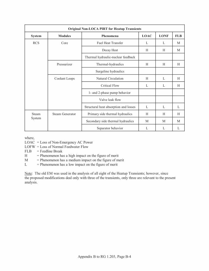
Appendix B to RG 1.203, Page B-4
Original Non-LOCA PIRT for Heatup Transients
System Modules Phenomena LOAC LONF FLB
RCS Core Fuel Heat Transfer L L M
Decay Heat H H M
Thermal hydraulic-nuclear feedback
Pressurizer Thermal-hydraulics H H H
Surgeline hydraulics
Coolant Loops Natural Circulation H L H
Critical Flow L L H
1- and 2-phase pump behavior
Valve leak flow
Structural heat absorption and losses L L L
SteamSystem
Steam Generator Primary side thermal hydraulics H H H
Secondary side thermal hydraulics M M M
Separator behavior L L L
where,LOAC = Loss of Non-Emergency AC PowerLOFW = Loss of Normal Feedwater FlowFLB = Feedline BreakH = Phenomenon has a high impact on the figure of meritM = Phenomenon has a medium impact on the figure of meritL = Phenomenon has a low impact on the figure of merit
Note: The old EM was used in the analysis of all eight of the Heatup Transients; however, sincethe proposed modifications deal only with three of the transients, only three are relevant to the presentanalysis.
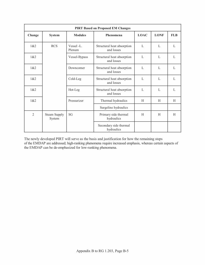
Appendix B to RG 1.203, Page B-5
PIRT Based on Proposed EM Changes
Change System Modules Phenomena LOAC LONF FLB
1&2 RCS Vessel -L.Plenum
Structural heat absorptionand losses
L L L
1&2 Vessel-Bypass Structural heat absorptionand losses
L L L
1&2 Downcomer Structural heat absorptionand losses
L L L
1&2 Cold-Leg Structural heat absorptionand losses
L L L
1&2 Hot-Leg Structural heat absorptionand losses
L L L
1&2 Pressurizer Thermal hydraulics H H H
Surgeline hydraulics
2 Steam SupplySystem
SG Primary side thermalhydraulics
H H H
Secondary side thermalhydraulics
The newly developed PIRT will serve as the basis and justification for how the remaining stepsof the EMDAP are addressed; high-ranking phenomena require increased emphasis, whereas certain aspects ofthe EMDAP can be de-emphasized for low-ranking phenomena.
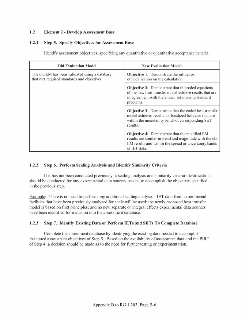
Appendix B to RG 1.203, Page B-6
1.2 Element 2 - Develop Assessment Base
1.2.1 Step 5. Specify Objectives for Assessment Base
Identify assessment objectives, specifying any quantitative or quantitative acceptance criteria.
Old Evaluation Model New Evaluation Model
The old EM has been validated using a databasethat met required standards and objectives
Objective 1: Demonstrate the influenceof nodalization on the calculation.
Objective 2: Demonstrate that the coded equationsof the new heat transfer model achieve results that arein agreement with the known solutions to standardproblems.
Objective 3: Demonstrate that the coded heat transfermodel achieves results for localized behavior that arewithin the uncertainty bands of corresponding SETresults.
Objective 4: Demonstrate that the modified EMresults are similar in trend and magnitude with the oldEM results and within the spread or uncertainty bandsof IET data.
1.2.2 Step 6. Perform Scaling Analysis and Identify Similarity Criteria
If it has not been conducted previously, a scaling analysis and similarity criteria identificationshould be conducted for any experimental data sources needed to accomplish the objectives specifiedin the previous step.
Example: There is no need to perform any additional scaling analyses. IET data from experimentalfacilities that have been previously analyzed for scale will be used; the newly proposed heat transfermodel is based on first principles; and no new separate or integral effects experimental data sourceshave been identified for inclusion into the assessment database.
1.2.3 Step 7. Identify Existing Data or Perform IETs and SETs To Complete Database
Complete the assessment database by identifying the existing data needed to accomplishthe stated assessment objectives of Step 5. Based on the availability of assessment data and the PIRTof Step 4, a decision should be made as to the need for further testing or experimentation.
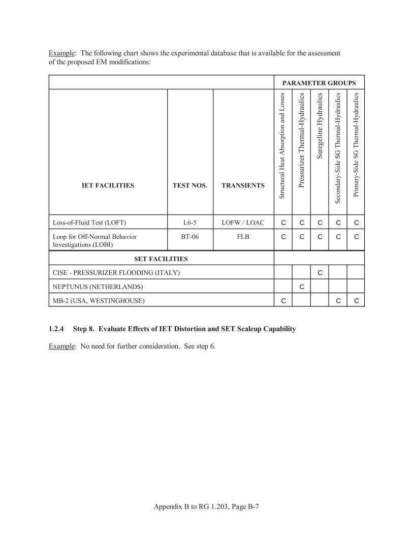
Appendix B to RG 1.203, Page B-7
Example: The following chart shows the experimental database that is available for the assessmentof the proposed EM modifications:
PARAMETER GROUPS
IET FACILITIES TEST NOS. TRANSIENTS
Stru
ctur
al H
eat A
bsor
ptio
n an
d Lo
sses
Pres
suriz
er T
herm
al-H
ydra
ulic
s
Sure
gelin
e H
ydra
ulic
s
Seco
ndar
y-Si
de S
G T
herm
al-H
ydra
ulic
s
Prim
ary-
Side
SG
The
rmal
-Hyd
raul
ics
Loss-of-Fluid Test (LOFT) L6-5 LOFW / LOAC C C C C C
Loop for Off-Normal BehaviorInvestigations (LOBI)
BT-06 FLB C C C C C
SET FACILITIES
CISE - PRESSURIZER FLOODING (ITALY) C
NEPTUNUS (NETHERLANDS) C
MB-2 (USA, WESTINGHOUSE) C C C
1.2.4 Step 8. Evaluate Effects of IET Distortion and SET Scaleup Capability
Example: No need for further consideration. See step 6.
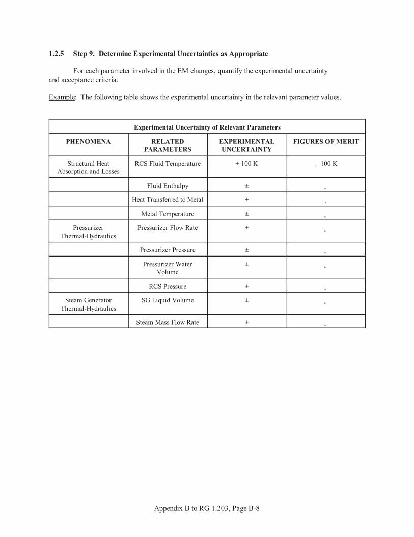
Appendix B to RG 1.203, Page B-8
1.2.5 Step 9. Determine Experimental Uncertainties as Appropriate
For each parameter involved in the EM changes, quantify the experimental uncertaintyand acceptance criteria.
Example: The following table shows the experimental uncertainty in the relevant parameter values.
Experimental Uncertainty of Relevant Parameters
PHENOMENA RELATEDPARAMETERS
EXPERIMENTALUNCERTAINTY
FIGURES OF MERIT
Structural HeatAbsorption and Losses
RCS Fluid Temperature ± 100 K ˜ 100 K
Fluid Enthalpy ± ˜
Heat Transferred to Metal ± ˜
Metal Temperature ± ˜
PressurizerThermal-Hydraulics
Pressurizer Flow Rate ± ˜
Pressurizer Pressure ± ˜
Pressurizer WaterVolume
± ˜
RCS Pressure ± ˜
Steam GeneratorThermal-Hydraulics
SG Liquid Volume ± ˜
Steam Mass Flow Rate ± ˜
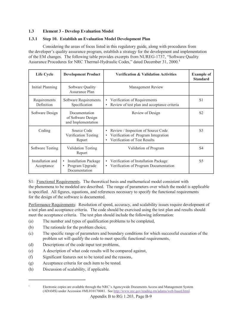
1 Electronic copies are available through the NRC’s Agencywide Documents Access and Management System(ADAMS) under Accession #ML010170081. See http://www.nrc.gov/reading-rm/adams/web-based.html.
Appendix B to RG 1.203, Page B-9
1.3 Element 3 - Develop Evaluation Model
1.3.1 Step 10. Establish an Evaluation Model Development Plan
Considering the areas of focus listed in this regulatory guide, along with procedures fromthe developer’s quality assurance program, establish a strategy for the development and implementationof the EM changes. The following table provides excerpts from NUREG-1737, “Software QualityAssurance Procedures for NRC Thermal-Hydraulic Codes,” dated December 31, 2000.1
Life Cycle Development Product Verification & Validation Activities Example ofStandard
Initial Planning Software QualityAssurance Plan
Management Review
RequirementsDefinition
Software RequirementsSpecification
• Verification of Requirements• Review of test plan and acceptance criteria
S1
Software Design Documentationof Software Designand Implementation
Review of Design S2
Coding Source CodeVerification Testing
Report
• Review / Inspection of Source Code• Verification of Program Integration • Verification of Test Results
S3
Software Testing Validation TestingReport
Validation of Program S4
Installation andAcceptance
• Installation Package• Program Upgrade
Documentation
• Verification of Installation Package• Verification of Program Documentation
S5
S1: Functional Requirements. The theoretical basis and mathematical model consistent withthe phenomena to be modeled are described. The range of parameters over which the model is applicableis specified. All figures, equations, and references necessary to specify the functional requirementsfor the design of the software is documented.
Performance Requirements: Resolution of speed, accuracy, and scalability issues require development ofa test plan and acceptance criteria. The code should be exercised using the test plan and results shouldmeet the acceptance criteria. The test plan should include the following information:(a) The number and types of qualification problems to be completed,(b) The rationale for the problem choice,(c) The specific range of parameters and boundary conditions for which successful execution of the
problem set will qualify the code to meet specific functional requirements,(d) Descriptions of the code input test problems,(e) A description of what code results will be compared against,(f) Significant features not to be tested and the reasons,(g) Acceptance criteria for each item to be tested.(h) Discussion of scalability, if applicable.

Appendix B to RG 1.203, Page B-10
Validation Requirements:
“Excellent Agreement” applies when the code exhibits no deficiencies in modeling a given behavior. Major and minor phenomena and trends are correctly predicted. The calculated results are judgedto agree closely with data.
“Reasonable Agreement” applies when the code exhibits minor deficiencies. Overall, the code providesan acceptable prediction. All major trends and phenomena are predicted correctly. Differences betweencalculated values and data are greater than are deemed necessary for excellent agreement.
“Minimal Agreement” applies when the code exhibits significant deficiencies. Overall, the code providesa prediction that is not acceptable. Some major trends or phenomena are not predicted correctly,and some calculated values lie considerably outside the specified or inferred uncertainty bands of the data.
“Insufficient Agreement” applies when the code exhibits major deficiencies. The code providesan unacceptable prediction of the test data because major trends are not predicted correctly. Most calculated values lie outside the specified or inferred uncertainty bands of the data.
For PIRT high-ranked phenomena, the minimum standard for acceptability with respect to fidelityis generally “reasonable agreement.”
S2: The software design and implementation documentation shall describe the logical structure,information flow, data structures, the subroutine and function calling hierarchy, variable definitions,identification of inputs and outputs, and other relevant parameters. It shall include a tree showingthe relationship among the modules and a database describing each module, array, variables, and otherparameters used among code modules.
S3: The source code listing or update listing shall be reviewed for the following attributes. There will besufficient explanations in the listing which will permit review of these attributes:(a) Traceability between the source code and the corresponding design specification:
Analyze coding for correctness, consistency, completeness, and accuracy.(b) Functionality: Evaluate coding for correctness, consistency, completeness, accuracy, and testability.
Also, evaluate design specifications for compliance with established standards, practices,and conventions. Assess source code quality.
(c) Interfaces: Evaluate coding with hardware, operator, and software interface design documentation forcorrectness, consistency, and accuracy. At a minimum, analyze data items at each interface.
S4: All testing activities shall be documented and shall include information on the date of the test,code version tested, test executed, discussion of the test results, and whether the software meetsthe acceptance test criteria.
S5:Installation Package: The program installation package shall consist of program installation procedures,files of the program, selected test cases for use in verifying installation, and expected output fromthe test cases.
Upgrading Program Documentation: The existing program documentation shall be revised and enhancedto provide a complete description of the program. Code manuals will be produced and upgradedconcurrently with the code development process. The set of code manuals will cover the followingsubjects: Theory, Models & Correlations Manual; User’s Manual; Programmer’s Manual;and Developmental Assessment Manual.

Appendix B to RG 1.203, Page B-11
1.3.2 Step 11. Establish Evaluation Model Structure
In accordance with the plan outlined in the previous step and this regulatory guide, describethe structure of the new methodologies. Describe how each is integrated into the EM (ie., written intothe source code, input as a user defined function, etc.).
Example:Change 1: The new heat transfer model will be written in FORTRAN and input using the User-DefinedSubroutine option available in CODE1. The subroutine will only be used for the specific metal structuresidentified for the modification.
Change 2: CODE1 and AUX1 will receive the same input parameters and boundary conditions,and each code will run until a steady state is reached. From this point, AUX1 will be restartedfor transient initiation and allowed to run to completion. The steam generator mass outputs from AUX1will then be input as a tabular function at the restart of the CODE1 calculation. CODE1 will then rununtil completion of the transient.
In both cases, the requirements for the design of the software will be done in accordance withthe plan described in the previous step. At a minimum, they will include the nodalization, defenseof the chosen parameters, any needed sensitivity studies, and justification of the conservative natureof the input parameters.
1.3.3 Step 12. Develop or Incorporate Closure Models
Example:In the strictest sense, the newly proposed heat transfer equation is not a closure model,
but a variation of the heat conduction field equation currently used in the EM. However, because itsapplication is based on particular geometries, the separate effects of the phenomenon must be assessedin the same manner as closure models.
At this point in the EMDAP, the proposed EM modifications are incorporated into the old EM,creating a newly revised EM. From this point forward, the EMDAP will be followed to assess the newlyrevised EM as a whole.
1.4 Element 4 - Assess Evaluation Model Adequacy
1.4.1 Step 13. Determine Model Pedigree and Applicability To Simulate Physical Processes
Example:The information for the determination of model pedigree and applicability is given in accordance withthe model development plan. For the change in the heat conduction equation, the assumption ofa uniform temperature distribution within the metal must be justified. This allows for the use ofthe proposed heat transfer solution technique. For the model pedigree determination, informationis provided showing that the internal resistance of the metal is negligible in comparison with the externalresistance at its surface and that the Biot number is less than 0.1. In determining applicability,a consistency evaluation is conducted on the discretized heat equation. By expanding the equation usinga Taylor series and rounding off the truncation error, the discretized equation is shown to be consistentwith the analytical equation. The determination of model pedigree and applicability was conductedin the initial assessment of AUX1. The assessment of its incorporation into the EM will begin in Step 16.

Appendix B to RG 1.203, Page B-12
1.4.2 Step 14. Prepare Input and Perform Calculations To Assess Model Fidelity or Accuracy
Perform as directed.
1.4.3 Step 15. Assess Scalability of Models
Example:The scaling issue was resolved in Step 6.
1.4.4 Step 16. Determine Capability of Field Equations to Represent Processes and Phenomenaand the Ability of Numeric Solutions to Approximate Equation Set
Example:In the heat transfer modification, the coupling of the fuel/structural heat transfer to the thermal-hydraulicfluid behavior has not been altered, so there’s no need to evaluate the remaining field equations whichhave been reviewed previously. It is determined that there are no restrictions on the solution’s rangeof applicability and that no additional constitutive relations are needed. Also, the new solution techniqueis in no way related to any restrictions placed on the usage of CODE1 in the codes original safety evaluationreport (SER). In the numeric solution evaluation, the key focus is the accuracy, stability, and convergenceof code calculations to a solution of the original equations. In this review, the solution techniqueis shown to be accurate and numerically stable for any time step; errors approach zero as the thicknessand time step approach zero, and errors due to finite thicknesses and large time steps always occurin the direction to minimize heat transfer. For Change 2, the field equations and numerics ofthe AUX1 code were validated in the initial assessment; therefore, no further consideration is required.
1.4.5 Step 17. Determine Applicability of Evaluation Model to Simulate Systems and Components
Example:The applicability of the EM to simulate systems and components was determined and documentedin the initial assessment of the old EM and AUX1. The applicability of the new heat conduction equationwas determined in Step 13.
1.4.6 Step 18. Prepare Input and Perform Calculations to assess System Interactionsand Global Capability
Perform as directed.
1.4.7 Step 19. Assess Scalability of Integral Calculations and Data for Distortions
Example:Evaluate the code results according to the specified acceptance criteria. If distortions are present,assess the scalability of the integral calculation.
1.4.8 Step 20. Determine Evaluation Model Biases and Uncertainties
Due to the relatively small nature of the changes, no uncertainty analysis is warranted. Therefore, provide a qualitative statement on the degree of conservatism embedded in the EM,describing assumptions or input values that ensure conservatism in the analysis.
1.5 Adequacy Decision
Based on the comparisons made in Step 18, the model change is judged adequate or not.