reidbar™ reinforcing connection systems
TRANSCRIPT
ReidBar™ ReinforcingConnection SystemsProduct and Specification Guide
Engineered full strength
reinforcing connections
systems
reids.co.nz | 0800 88 22 12
August | 2021
BRANZ-CM-1024

Genuine ReidBar™ is a continuously threaded, hot rolled Grade 500E reinforcing bar manufactured in New Zealand in accordance to AS/NZS4671:2019.
Genuine ReidBar™ Connection Systems deliver Optimised Reinforcing Connection solutions designed to increase structural system integrity, simplify complex connections and reduce cost in place. All ReidBarTM Bar and ReidBar™ Connection Systems are manufactured within quality-controlled tolerances (ISO:9001) and tested In-Concrete with 3rd Party verification ensuring performance as a Genuine matched system.
| ReidBar™ Product and Specification Guide
Applic
ations Column-to-Beam
Connections
Column/ Pile Caps
Stitch Joints
Wall-to-Slab Connections
Genuine ReidBar™
BRANZ-CM-1024
CodeMark’s Scheme Mark of Conformity
2 spec & install guide | reidbar™ components
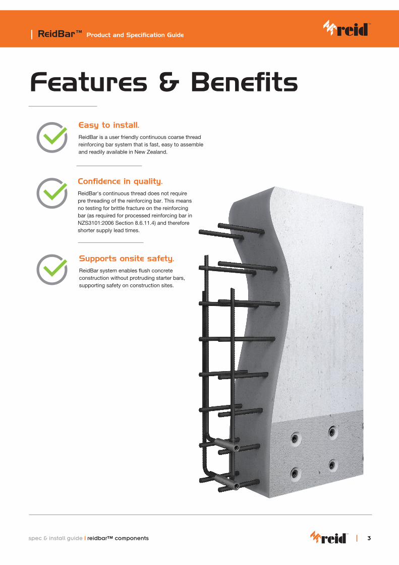
Features & BenefitsEasy to install.ReidBar is a user friendly continuous coarse thread reinforcing bar system that is fast, easy to assemble and readily available in New Zealand.
Confidence in quality.ReidBar's continuous thread does not require pre threading of the reinforcing bar. This means no testing for brittle fracture on the reinforcing bar (as required for processed reinforcing bar in NZS3101:2006 Section 8.6.11.4) and therefore shorter supply lead times.
Supports onsite safety.ReidBar system enables flush concrete construction without protruding starter bars, supporting safety on construction sites.
| ReidBar™ Product and Specification Guide
33spec & install guide | reidbar™ components
CodeMark
ReidBar™ Reinforcing Connection Systems hold a CodeMark certificate (Certificate Number BRANZ-CM-1024). This provides a deemed to comply assessment for the system, to the NZBC, when used within the scope of CodeMark Certificate Number BRANZ-CM-1024.
What is CodeMark? CodeMark is a product certification scheme for building methods and products.
What does CodeMark do? CodeMark certification provides assurance that a product is ‘deemed to comply’ with the New Zealand Building Code.
Benefits of CodeMark certification of ReidBar™ Reinforcing Connection Systems?• Provides assurance that ReidBar™ Reinforcing Connection Systems are ‘deemed to comply’ with the
clauses of the NZBC stated on CodeMark Certificate Number BRANZ-CM-1024 (refer to the Compliance section for a listing of the NZBC clauses this system is compliant to and the CodeMark certificate link).
• ReidBar™ Reinforcing Connection System’ CodeMark certification is reviewed by BRANZ annually
Where can I find the CodeMark certificate?The ReidBar™ Reinforcing Connection System CodeMark certificate is available on the JAS-ANZ website, located by entering the certificate number. https://www.jas-anz.org/our-directory/codemark-certified-organisations
Finding more information about the ReidBar™ Reinforcing Connection System?• Please refer to supporting literature available from www.reids.co.nz
How do I ensure compliance to the CodeMark conditions?The ReidBar™ Reinforcing Connection System is an engineered system.
Substitution, omission and/or modification of components is not permitted by and will void the CodeMark certification of the system.
For more information refer to the CodeMark certificate located by using the link above and the Compliance, System Components and Specification Toolkit sections of this publication.
Want to know more about the ReidBar™ Reinforcing Connection Systems and CodeMark certification? Contact the Reid team for advice.
customer serviceReid™ New Zealand Customer Service CentreTel: 0800 88 22 12 Email: [email protected]: www.reids.co.nz
BRANZ-CM-1024
| ReidBar™ Product and Specification Guide
4 spec & install guide | reidbar™ components

| ReidBar™ Product and Specification Guide
55
Typical specification on drawings: “RB__CS/CSG + Ramset EPCON C8 Xtrem”
ReidBar Steel Coupler
Part No. Description Body Diameter (A) (mm)
Length (B) (mm)
Hex A/F (C) (mm)
Min Threaded Depth (mm)
RB12CS 12mm ReidBar Steel Coupler 32 130 26 50
RBA16CS 16mm ReidBar Steel Coupler 32 136 26 54
RB20CS 20mm ReidBar Steel Coupler 35 148 32 60
RB25CS 25mm ReidBar Steel Coupler 42 193 38 80
RB32CS 32mm ReidBar Steel Coupler 60 242 52 102
RB12CSG* 12mm ReidBar Steel Coupler Galvanised 32 130 26 50
RBA16CSG* 16mm ReidBar Steel Coupler Galvanised 32 136 26 54
RB20CSG* 20mm ReidBar Steel Coupler Galvanised 35 148 32 60
RB25CSG* 25mm ReidBar Steel Coupler Galvanised 42 193 38 80
RB32CSG* 32mm ReidBar Steel Coupler Galvanised 60 242 52 102
Installation
*Additional lead times apply for HDG products
Part No. No of Injections (each side)* Approx. Fittings/cartridge**
RB12CS/CSG 3 15
RBA16CS/CSG 3 15
RB20CS/CSG 4 11
RB25CS/CSG 6 7
RB32CS/CSG 8 5
Recommended amount of EPCONTM C8 XtremTM injections
*recommendations are based on the use of mixing nozzle type “ISNE”. Quantities based on full pumps. **Based on 90 pumps per EPCONTM C8 XtremTM cartridge.
Product Specs
B
A
C
ReidBarTM Steel Couplers are to be Installed utilising RamsetTM EPCONTM C8 XtremTM
BRANZ-CM-1024
spec & install guide | reidbar™ components
| ReidBar™ Product and Specification Guide
6
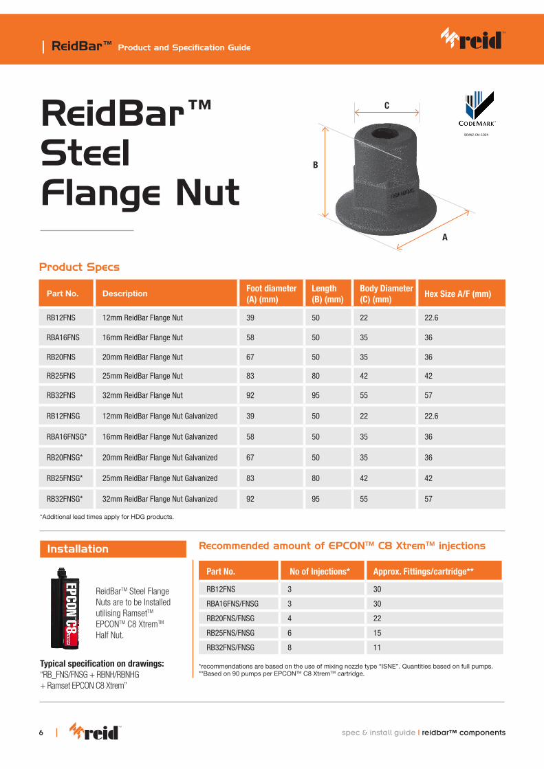
ReidBar™ Steel Flange Nut
Typical specification on drawings: “RB_FNS/FNSG + RBNH/RBNHG + Ramset EPCON C8 Xtrem”
Part No. Description Foot diameter (A) (mm)
Length (B) (mm)
Body Diameter (C) (mm)
Hex Size A/F (mm)
RB12FNS 12mm ReidBar Flange Nut 39 50 22 22.6
RBA16FNS 16mm ReidBar Flange Nut 58 50 35 36
RB20FNS 20mm ReidBar Flange Nut 67 50 35 36
RB25FNS 25mm ReidBar Flange Nut 83 80 42 42
RB32FNS 32mm ReidBar Flange Nut 92 95 55 57
RB12FNSG 12mm ReidBar Flange Nut Galvanized 39 50 22 22.6
RBA16FNSG* 16mm ReidBar Flange Nut Galvanized 58 50 35 36
RB20FNSG* 20mm ReidBar Flange Nut Galvanized 67 50 35 36
RB25FNSG* 25mm ReidBar Flange Nut Galvanized 83 80 42 42
RB32FNSG* 32mm ReidBar Flange Nut Galvanized 92 95 55 57
Installation
*Additional lead times apply for HDG products.
Part No. No of Injections* Approx. Fittings/cartridge**
RB12FNS 3 30
RBA16FNS/FNSG 3 30
RB20FNS/FNSG 4 22
RB25FNS/FNSG 6 15
RB32FNS/FNSG 8 11
Recommended amount of EPCONTM C8 XtremTM injections
*recommendations are based on the use of mixing nozzle type “ISNE”. Quantities based on full pumps. **Based on 90 pumps per EPCONTM C8 XtremTM cartridge.
Product Specs
A
B
C
ReidBarTM Steel Flange Nuts are to be Installed utilising RamsetTM EPCONTM C8 XtremTM Half Nut.
BRANZ-CM-1024
spec & install guide | reidbar™ components

| ReidBar™ Product and Specification Guide
77
ReidBar™ Steel Threaded Insert
Typical specification on drawings: “RB__TIS/TISG + Ramset EPCON C8 Xtrem”
Part No. Description Foot Minor Diameter (A) (mm)
Foot Major Diameter (B) (mm)
Length (C) (mm)
Body Diameter (D) (mm)
Min Threaded Depth (mm)
RB12TIS12mm ReidBar Steel Threaded Insert
37 39 101 22 53
RBA16TIS16mm ReidBar Steel Threaded Insert
53 55 118 30 58
RB20TIS20mm ReidBar Steel Threaded Insert
68 73 149 35 64
RB12TISG*12mm ReidBar Steel Threaded Insert Galvanised
37 39 101 22 53
RBA-16TISG*
16mm ReidBar Steel Threaded Insert Galvanised
53 55 118 30 58
RB20TISG*20mm ReidBar Steel Threaded Insert Galvan-ised
68 73 149 35 64
Installation
*Additional lead times apply for HDG products.
Part No. No of Injections* Approx. Fittings/cartridge**
RB12TIS/TISG 4 22
RBA16TIS/TISG 4 22
RB20TIS 5 18
Recommended amount of EPCONTM C8 XtremTM injections
*recommendations are based on the use of mixing nozzle type “ISNE”. Quantities based on full pumps. **Based on 90 pumps per EPCONTM C8 XtremTM cartridge. Start from the bottom of the thread and draw the nozzle out from the component in a rotating motion as the filler is being injected.
Product Specs
C
D
A
B
ReidBarTM Steel Threaded Inserts are to be Installed utilising RamsetTM EPCONTM C8 XtremTM
BRANZ-CM-1024
spec & install guide | reidbar™ components

| ReidBar™ Product and Specification Guide
spec & install guide | reidbar™ components 8
ReidBar™ Ductile Cast Iron Threaded Inserts
Typical specification on drawings: “RB_TI/TIG + Ramset EPCON C8 Xtrem”
Part No. Description Foot Diameter (A) (mm)
Length (B)(mm)
Body Diameter (C) (mm)
Min Threaded Depth (mm)
RB12TI 12mm ReidBar Threaded Insert 38 99 22 55
RBA16TI 16mm ReidBar Threaded Insert 50 118 30 50
RB20TI 20mm ReidBar Threaded Insert 64 149 35 64
RB12TIG*12mm ReidBar Threaded Insert Galvanised
38 99 22 55
RBA16TIG*16mm ReidBar Threaded Insert Galvanised
50 118 30 50
RB20TIG* 20mm ReidBar Threaded Insert Galvanised 64 149 35 64
Installation
*Additional lead times apply for HDG products.
Part No. No of Injections* Approx. Fittings/cartridge**
RB12TI/TIG 4 22
RBA16TI/TIG 5 20
RB20TI 6 16
Recommended amount of EPCONTM C8 XtremTM injections
*recommendations are based on the use of mixing nozzle type “ISNE”. Quantities based on full pumps. **Based on 90 pumps per EPCONTM C8 XtremTM cartridge. Start from the bottom of the thread and draw the nozzle out from the component in a rotating motion as the filler is being injected.
Product Specs
B
C
A
ReidBarTM Threaded Inserts are to be Installed utilising RamsetTM EPCONTM C8 XtremTM.
BRANZ-CM-1024
spec & install guide | reidbar™ components
| ReidBar™ Product and Specification Guide
99
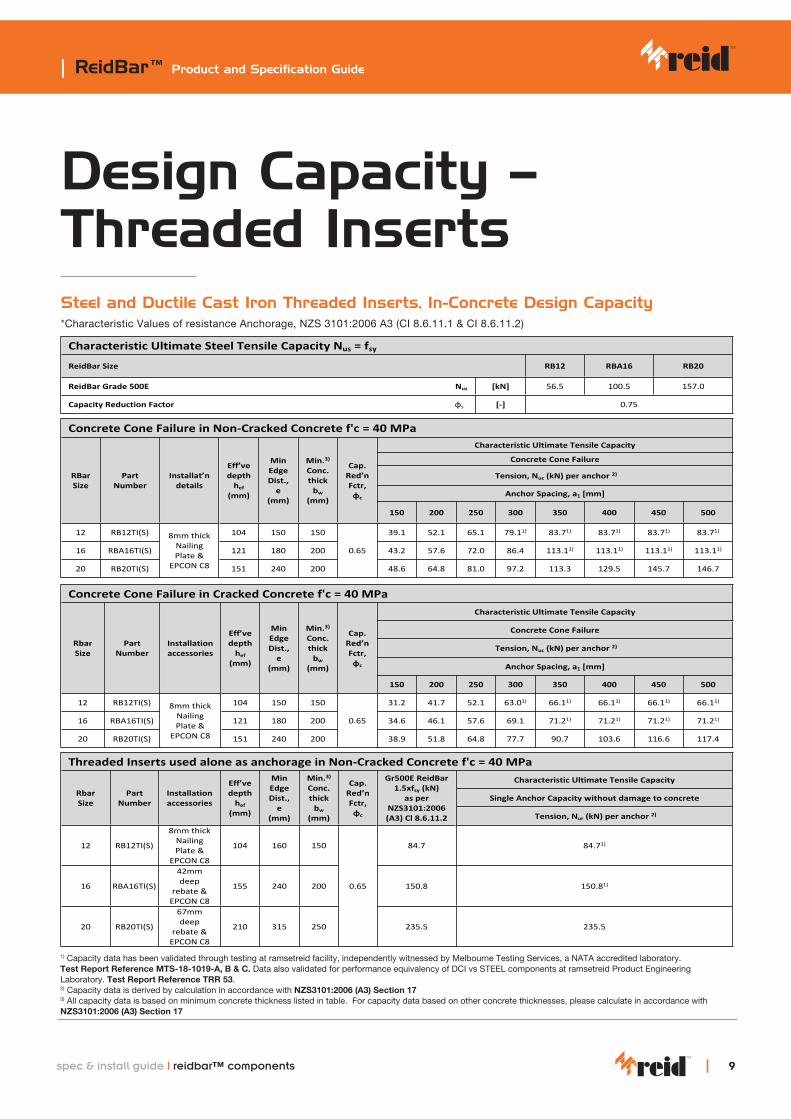
Design Capacity – Threaded InsertsSteel and Ductile Cast Iron Threaded Inserts, In-Concrete Design Capacity *Characteristic Values of resistance Anchorage, NZS 3101:2006 A3 (CI 8.6.11.1 & CI 8.6.11.2)
Table C3: Characteristic values of resistance Anchorage: Cl 8.6.11.1 & Cl 8.6.11.2 - NZS 3101:2006 A3
Characteristic Ultimate Steel Tensile Capacity Nus = fsy
ReidBar Size RB12 RBA16 RB20
ReidBar Grade 500E Nus [kN] 56.5 100.5 157.0
Capacity Reduction Factor φs [-] 0.75
Concrete Cone Failure in Non-Cracked Concrete f'c = 40 MPaCharacteristic Ultimate Tensile Capacity
Concrete Cone Failure
Tension, Nuc (kN) per anchor 2)
Anchor Spacing, a1 [mm]
RBar Size
Part Number
Installat’n details
Eff’ve depth
hef (mm)
Min Edge Dist.,
e (mm)
Min.3)
Conc.thick
bw (mm)
Cap. Red’n Fctr, φc
150 200 250 300 350 400 450 500
12 RB12TI(S) 104 150 150 39.1 52.1 65.1 79.11) 83.71) 83.71) 83.71) 83.71)
16 RBA16TI(S) 121 180 200 43.2 57.6 72.0 86.4 113.11) 113.11) 113.11) 113.11)
20 RB20TI(S)
8mm thick Nailing Plate &
EPCON C8 151 240 200
0.65
48.6 64.8 81.0 97.2 113.3 129.5 145.7 146.7
Concrete Cone Failure in Cracked Concrete f'c = 40 MPaCharacteristic Ultimate Tensile Capacity
Concrete Cone Failure
Tension, Nuc (kN) per anchor 2)
Anchor Spacing, a1 [mm]
Rbar Size
Part Number
Installation accessories
Eff’ve depth
hef (mm)
Min Edge Dist.,
e (mm)
Min.3)
Conc. thick
bw (mm)
Cap. Red’n Fctr, φc
150 200 250 300 350 400 450 500
12 RB12TI(S) 104 150 150 31.2 41.7 52.1 63.01) 66.11) 66.11) 66.11) 66.11)
16 RBA16TI(S) 121 180 200 34.6 46.1 57.6 69.1 71.21) 71.21) 71.21) 71.21)
20 RB20TI(S)
8mm thick Nailing Plate &
EPCON C8 151 240 200
0.65
38.9 51.8 64.8 77.7 90.7 103.6 116.6 117.4
Threaded Inserts used alone as anchorage in Non-Cracked Concrete f'c = 40 MPaCharacteristic Ultimate Tensile Capacity
Single Anchor Capacity without damage to concrete Rbar Size
Part Number
Installation accessories
Eff’ve depth
hef (mm)
Min Edge Dist.,
e (mm)
Min.3)
Conc. thick
bw (mm)
Cap. Red’n Fctr, φc
Gr500E ReidBar 1.5xfsy (kN)
as per NZS3101:2006 (A3) Cl 8.6.11.2 Tension, Nur (kN) per anchor 2)
12 RB12TI(S)
8mm thick Nailing Plate &
EPCON C8
104 160 150 84.7 84.71)
16 RBA16TI(S)
42mm deep
rebate & EPCON C8
155 240 200 150.8 150.81)
20 RB20TI(S)
67mm deep
rebate & EPCON C8
210 315 250
0.65
235.5 235.5
1) Capacity data has been validated through testing at ramsetreid facility, independently witnessed by Melbourne Testing Services, a NATA accreditedlaboratory. Test Report Reference MTS-18-1019-A, B & C.
Data also validated for performance equivalency of DCI vs STEEL components at ramsetreid Product Engineering Laboratory. Test Report Reference TRR 53.2) Capacity data is derived by calculation in accordance with NZS3101:2006 (A3) Section 173) All capacity data is based on minimum concrete thickness listed in table. For capacity data based on other concrete thicknesses, please calculate in
accordance with NZS3101:2006 (A3) Section 17
ReidBar Reinforcing Bar SystemPerformances: AnchorageAccording to NZS3101:2006 A3 & AS/NZS 4671
Annex C3
Page 10 of 13 RTA-21/0011 issued on 21/05/2021Table C3: Characteristic values of resistance Anchorage: Cl 8.6.11.1 & Cl 8.6.11.2 - NZS 3101:2006 A3
Characteristic Ultimate Steel Tensile Capacity Nus = fsy
ReidBar Size RB12 RBA16 RB20
ReidBar Grade 500E Nus [kN] 56.5 100.5 157.0
Capacity Reduction Factor φs [-] 0.75
Concrete Cone Failure in Non-Cracked Concrete f'c = 40 MPaCharacteristic Ultimate Tensile Capacity
Concrete Cone Failure
Tension, Nuc (kN) per anchor 2)
Anchor Spacing, a1 [mm]
RBar Size
Part Number
Installat’n details
Eff’ve depth
hef (mm)
Min Edge Dist.,
e (mm)
Min.3)
Conc.thick
bw (mm)
Cap. Red’n Fctr, φc
150 200 250 300 350 400 450 500
12 RB12TI(S) 104 150 150 39.1 52.1 65.1 79.11) 83.71) 83.71) 83.71) 83.71)
16 RBA16TI(S) 121 180 200 43.2 57.6 72.0 86.4 113.11) 113.11) 113.11) 113.11)
20 RB20TI(S)
8mm thick Nailing Plate &
EPCON C8 151 240 200
0.65
48.6 64.8 81.0 97.2 113.3 129.5 145.7 146.7
Concrete Cone Failure in Cracked Concrete f'c = 40 MPaCharacteristic Ultimate Tensile Capacity
Concrete Cone Failure
Tension, Nuc (kN) per anchor 2)
Anchor Spacing, a1 [mm]
Rbar Size
Part Number
Installation accessories
Eff’ve depth
hef (mm)
Min Edge Dist.,
e (mm)
Min.3)
Conc. thick
bw (mm)
Cap. Red’n Fctr, φc
150 200 250 300 350 400 450 500
12 RB12TI(S) 104 150 150 31.2 41.7 52.1 63.01) 66.11) 66.11) 66.11) 66.11)
16 RBA16TI(S) 121 180 200 34.6 46.1 57.6 69.1 71.21) 71.21) 71.21) 71.21)
20 RB20TI(S)
8mm thick Nailing Plate &
EPCON C8 151 240 200
0.65
38.9 51.8 64.8 77.7 90.7 103.6 116.6 117.4
Threaded Inserts used alone as anchorage in Non-Cracked Concrete f'c = 40 MPaCharacteristic Ultimate Tensile Capacity
Single Anchor Capacity without damage to concrete Rbar Size
Part Number
Installation accessories
Eff’ve depth
hef (mm)
Min Edge Dist.,
e (mm)
Min.3)
Conc. thick
bw (mm)
Cap. Red’n Fctr, φc
Gr500E ReidBar 1.5xfsy (kN)
as per NZS3101:2006 (A3) Cl 8.6.11.2 Tension, Nur (kN) per anchor 2)
12 RB12TI(S)
8mm thick Nailing Plate &
EPCON C8
104 160 150 84.7 84.71)
16 RBA16TI(S)
42mm deep
rebate & EPCON C8
155 240 200 150.8 150.81)
20 RB20TI(S)
67mm deep
rebate & EPCON C8
210 315 250
0.65
235.5 235.5
1) Capacity data has been validated through testing at ramsetreid facility, independently witnessed by Melbourne Testing Services, a NATA accreditedlaboratory. Test Report Reference MTS-18-1019-A, B & C.
Data also validated for performance equivalency of DCI vs STEEL components at ramsetreid Product Engineering Laboratory. Test Report Reference TRR 53.2) Capacity data is derived by calculation in accordance with NZS3101:2006 (A3) Section 173) All capacity data is based on minimum concrete thickness listed in table. For capacity data based on other concrete thicknesses, please calculate in
accordance with NZS3101:2006 (A3) Section 17
ReidBar Reinforcing Bar SystemPerformances: AnchorageAccording to NZS3101:2006 A3 & AS/NZS 4671
Annex C3
Page 10 of 13 RTA-21/0011 issued on 21/05/2021
1) Capacity data has been validated through testing at ramsetreid facility, independently witnessed by Melbourne Testing Services, a NATA accredited laboratory. Test Report Reference MTS-18-1019-A, B & C. Data also validated for performance equivalency of DCI vs STEEL components at ramsetreid Product Engineering Laboratory. Test Report Reference TRR 53. 2) Capacity data is derived by calculation in accordance with NZS3101:2006 (A3) Section 17 3) All capacity data is based on minimum concrete thickness listed in table. For capacity data based on other concrete thicknesses, please calculate in accordance with NZS3101:2006 (A3) Section 17
| ReidBar™ Product and Specification Guide
10
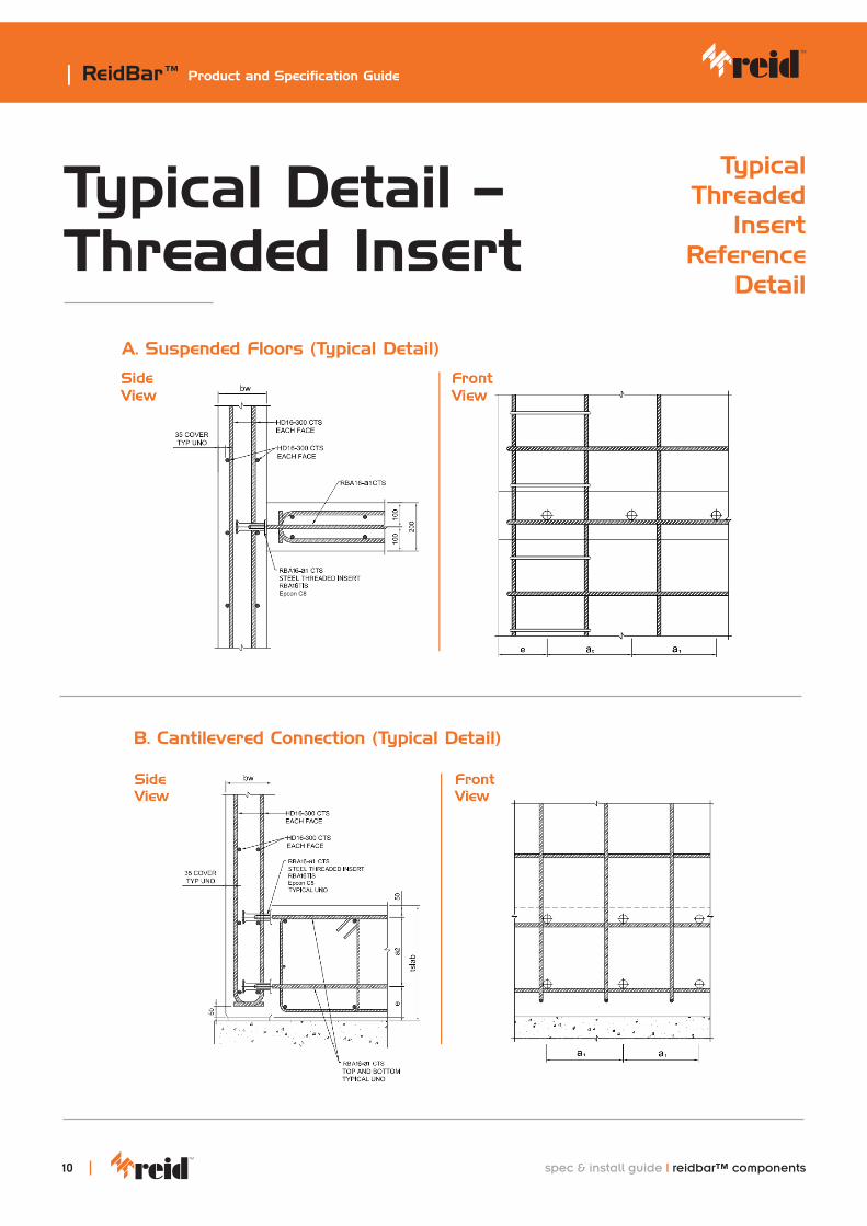
Typical Detail – Threaded Insert
A. Suspended Floors (Typical Detail)
B. Cantilevered Connection (Typical Detail)
Typical Threaded
Insert Reference
Detail
spec & install guide | reidbar™ components

| ReidBar™ Product and Specification Guide
1111
Inject the recommended number of pumps of EPCON C8 into the other side of the Steel Coupler.
Screw in the second ReidBar into the Steel Coupler, and tighten the bar using a wrench to ensure that the ReidBar is hard against the stop.
Wipe excess filler with cloth/fabric/carton.
4 5 6
INSTALLATION: ReidBar™ Steel Coupler
Steps
Inject the recommended number of pumps of EPCON C8 into one side of the Steel Coupler. Start from the bottom of the thread and draw the nozzle out from the component in a rotating motion as the filler is being injected.
Screw the Steel Coupler onto the first ReidBar, and tighten the coupler using a wrench to ensure that the ReidBar is hard against the stop.
Wipe excess filler with cloth/fabric/carton.
1 2 3
ReidBar Steel Coupler Installation Guidelines below:
Recommended filler injection quantity pg 5.
Ensure EPCON C8 is visible at the end of Coupler.
Ensure EPCON C8 is visible at the end of Coupler.
Recommended filler injection quantity pg 5.
Coupler end excess filler removed.
Coupler end excess filler removed.
Ensure the appropriate PPE is worn when working with RamsetTM EPCONTM C8 XtremTM. Refer to www.ramset.co.nz for EPCONTM C8 XtremTM MSDS Sheet.
Start from the bottom of the thread and draw the nozzle out from the component in a rotating motion as the filler is being injected.
spec & install guide | reidbar™ components
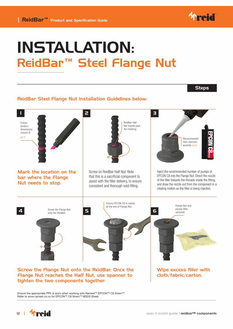
Screw the Flange Nut onto the ReidBar. Once the Flange Nut reaches the Half Nut, use spanner to tighten the two components together.
Wipe excess filler with cloth/fabric/carton.
4 6
INSTALLATION: ReidBar™ Steel Flange Nut
Steps
Mark the location on the bar where the Flange Nut needs to stop.
Screw on ReidBar Half Nut. Note that this is a sacrificial component to assist with the filler delivery, to ensure consistent and thorough void-filling.
Inject the recommended number of pumps of EPCON C8 into the Flange Nut. Direct the nozzle of the filler towards the threads inside the fitting, and draw the nozzle out from the component in a rotating motion as the filler is being injected.
1 2 3
ReidBar Steel Flange Nut Installation Guidelines below:
5
Recommended filler injection quantity pg 6.
Ensure EPCON C8 is visible at the end of Flange Nut.
ReidBar Half Nut travels past the marking.
Follow product dimensions column B
pg 6
Flange Nut end excess filler removed.
Ensure the appropriate PPE is worn when working with RamsetTM EPCONTM C8 XtremTM. Refer to www.ramset.co.nz for EPCONTM C8 XtremTM MSDS Sheet.
Screw the Flange Nut onto the ReidBar.
| ReidBar™ Product and Specification Guide
12 spec & install guide | reidbar™ components
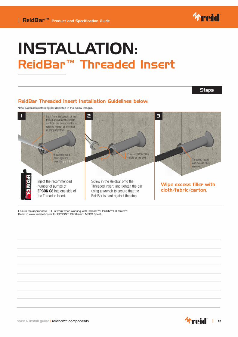
Threaded Insert end excess filler removed.
INSTALLATION: ReidBar™ Threaded Insert
Steps
ReidBar Threaded Insert Installation Guidelines below:
Inject the recommended number of pumps of EPCON C8 into one side of the Threaded Insert.
Wipe excess filler with cloth/fabric/carton.
1 2 3
Recommended filler injection quantity pg 7 & 8.
Ensure EPCON C8 is visible at the end.
Ensure the appropriate PPE is worn when working with RamsetTM EPCONTM C8 XtremTM. Refer to www.ramset.co.nz for EPCONTM C8 XtremTM MSDS Sheet.
Screw in the ReidBar onto the Threaded Insert, and tighten the bar using a wrench to ensure that the ReidBar is hard against the stop.
Note: Detailed reinforcing not depicted in the below images.
Start from the bottom of the thread and draw the nozzle out from the component in a rotating motion as the filler is being injected.
| ReidBar™ Product and Specification Guide
1313spec & install guide | reidbar™ components

NOTES
| ReidBar™ Product and Specification Guide
14 spec & install guide | reidbar™ components


Reid™ Construction Systems (RCS) 1 Ramset Drive, Chirnside Park 3116 Information in this document is correct at the time of printing. Readers should contact RCS or consult RCS detailed technical information to ensure product is suitable for intended use prior to purchase. ITW Australia Pty Ltd ABN 63 004 235 063 trading as RCS© copyright 2021. ™ Trademarks of Cetram Pty. Ltd. Used under license by RCS
Reid™ New Zealand Customer Service CentreTel: 0800 88 22 12 Email: [email protected]: www.reids.co.nz
customer service
Important Disclaimer: Any engineering information or advice (“Information”) provided by RCS in this document is issued in accordance with a prescribed standard, published performance data or design software. It is the responsibility of the user to obtain its own independent engineering (or other) advice to assess the suitability of the Information for its own requirements. To the extent permitted by law, RCS will not be liable to the recipient or any third party for any direct or indirect loss or liability arising out of, or in connection with, the Information.