reidbar steel components - reid nz | home
TRANSCRIPT
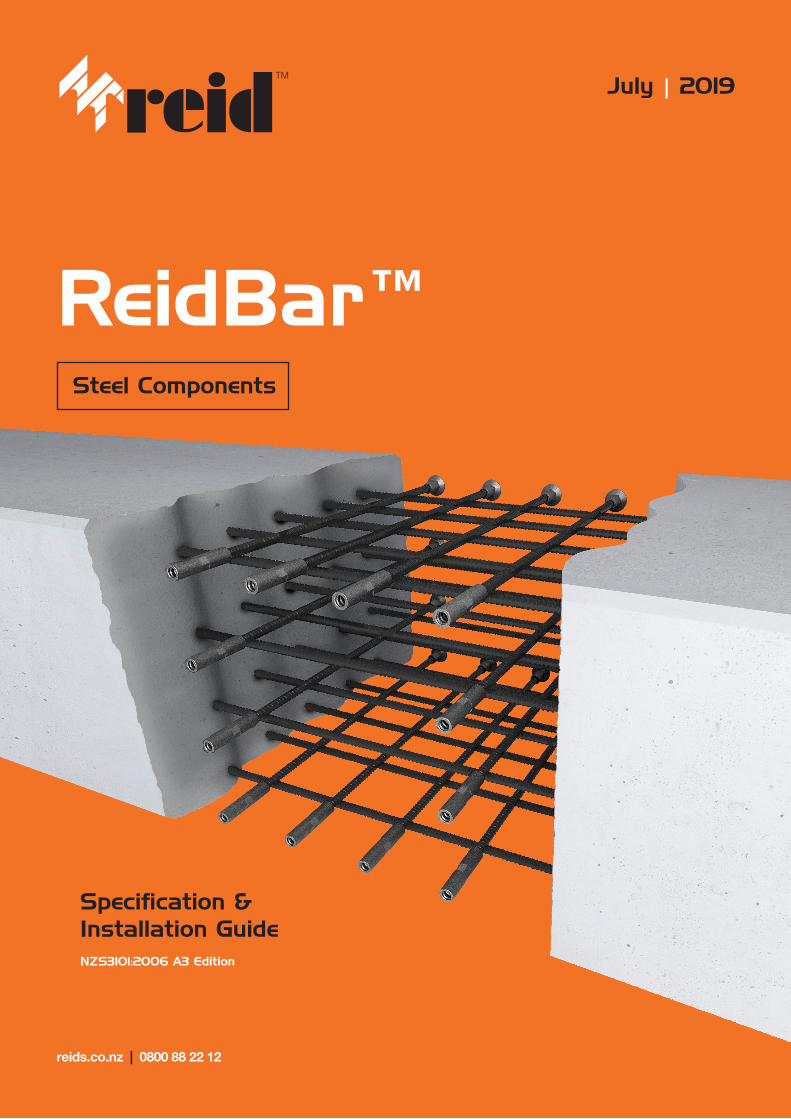
ReidBar™Steel Components
Specification & Installation Guide NZS3101:2006 A3 Edition
reids.co.nz | 0800 88 22 12
July | 2019
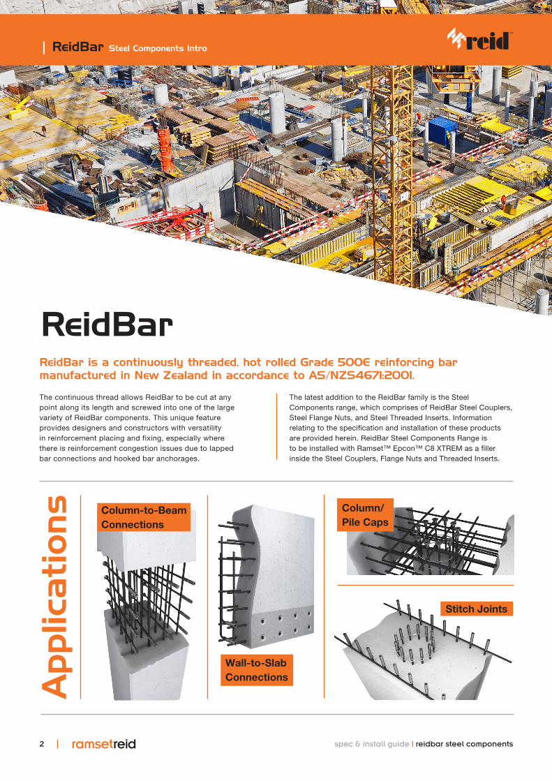
ReidBar is a continuously threaded, hot rolled Grade 500E reinforcing bar manufactured in New Zealand in accordance to AS/NZS4671:2001.
The continuous thread allows ReidBar to be cut at any point along its length and screwed into one of the large variety of ReidBar components. This unique feature provides designers and constructors with versatility in reinforcement placing and fixing, especially where there is reinforcement congestion issues due to lapped bar connections and hooked bar anchorages.
The latest addition to the ReidBar family is the Steel Components range, which comprises of ReidBar Steel Couplers, Steel Flange Nuts, and Steel Threaded Inserts. Information relating to the specification and installation of these products are provided herein. ReidBar Steel Components Range is to be installed with Ramset™ Epcon™ C8 XTREM as a filler inside the Steel Couplers, Flange Nuts and Threaded Inserts.
| ReidBar Steel Components Intro
Applic
ations Column-to-Beam
Connections
Column/ Pile Caps
Stitch Joints
Wall-to-Slab Connections
ReidBar
2 spec & install guide | reidbar steel components

Features & BenefitsEasy to install.ReidBar is a user friendly continuous coarse thread reinforcing bar system that is fast, easy to assemble and readily available in New Zealand.
Confidence in quality.ReidBar's continuous thread does not require pre threading of the reinforcing bar. This means no testing on the reinforcing bar (as referenced in NZS3101:2006 Section 8.6.11.4) for embrittlement failure and shorter supply lead times.
Supports onsite safety.ReidBar system enables flush concrete construction without protruding starter bars, supporting safety on construction sites.
spec & install guide | reidbar steel components 33
| ReidBar Features & Benefits / Compliance Information
Product Compliance Information
NZS3101:2006 A3 Clause
Criteria Compliant Products
Section 8.7.5.2(b)“Mechanical connections shall: ....... (b) when tested in tension or compression, as appropriate, to the application, exhibit a change in length at a stress of 0.7fy in the bar, measured over the length of the coupler, of less than twice that of an equal length of unspliced bar.”1
ReidBar Steel Coupler: 12mm, 16mm, 20mm, 25mm, 32mm
ReidBar Steel Flange Nut: 12mm, 16mm, 20mm, 25mm, 32mm
ReidBar Steel Threaded Insert: 12mm, 16mm, 20mm
Section 8.9.1.3(a) - Couplers Only*
“For welded splices or mechanical connections to be used in members that are subjected to seismic forces, such splices shall comply with 8.7.4.1 or 8.7.5.2. In addition to the requirements of 8.7.5.2, mechanical splices and anchorages shall satisfy the cyclic load performance require-ments specified by ISO 15835-1 and ISO 15835-2 as follows: (a) When tested in accordance with 5.6.2 of ISO 15835-2, the residual elongations after 4 cycles, u4,shall be less than 0.3 mm, and after 8 cycles u8 shall be less than 0.6 mm.”1
ReidBar Steel Coupler:12mm, 16mm, 20mm, 25mm, 32mm
Section 8.6.11.4**
“Mechanical anchors for the anchorage of reinforcing steel shall be proven by an appropriate test method to possess resistance to brittle fracture at the service temperatures at which they are intended for use. Where the mechanical anchors and ends of the bars are threaded as the means of achieving the connection between components, and/or the end of the bar is enlarged by cold forging prior to threading, appropriate testing of the processed bar end shall be applied to ensure that the potential for brittle fracture is avoided. Anchors manufactured from cast iron shall not be used.”1
ReidBar Steel Coupler:12mm, 16mm, 20mm, 25mm, 32mm
ReidBar Steel Flange Nut:12mm, 16mm, 20mm, 25mm, 32mm
ReidBar Steel Threaded Insert:12mm, 16mm, 20mm
*ISO 15835-1 and ISO 15835-2 do not provide guidance for testing of anchorage system.**Compliance with Section 8.6.11.4 was demonstrated via. Charpy V Notch Testing to AS1544.2:2003.1 Reference: NZS3101:2006 Amendment 3 2018
Note: Tensile Strength of ReidBar Steel Coupler, Steel Flange Nut and Steel Threaded Inserts exceeds upper bound breaking strength of the 500E ReidBar = 750MPa.

Typical specification on drawings: “RB__CS/CSG + Ramset Epcon C8 XTREM”
| ReidBar Steel Coupler Specs
ReidBar Steel Coupler
Part No. Description Body Diameter (A) (mm)
Length (B) (mm)
Hex A/F (C) (mm)
Min Threaded Depth (mm)
RB12CS 12mm ReidBar Steel Coupler 32 130 26 50
RBA16CS 16mm ReidBar Steel Coupler 32 136 26 54
RB20CS 20mm ReidBar Steel Coupler 35 148 32 60
RB25CS 25mm ReidBar Steel Coupler 42 193 38 80
RB32CS 32mm ReidBar Steel Coupler 60 242 52 102
RB12CSG* 12mm ReidBar Steel Coupler Galvanised 32 130 26 50
RBA16CSG* 16mm ReidBar Steel Coupler Galvanised 32 136 26 54
RB20CSG* 20mm ReidBar Steel Coupler Galvanised 35 148 32 60
RB25CSG* 25mm ReidBar Steel Coupler Galvanised 42 193 38 80
RB32CSG* 32mm ReidBar Steel Coupler Galvanised 60 242 52 102
Installation
*Additional lead time apply for HDG products
Part No. No of Injections (each side)* Approx. Fittings/cartridge**
RB12CS/CSG 3 15
RBA16CS/CSG 3 15
RB20CS/CSG 4 11
RB25CS/CSG 6 7
RB32CS/CSG 8 5
Recommended amount of Epcon C8 XTREM injections
*recommendations are based on the use of mixing nozzle type “ISNE”. Quantities based on full pumps. **Based on 90 pumps per Epcon C8 XTREM cartridge.
4
Product Specs
B
A
C
ReidBar Steel Couplers, Flange Nut and Threaded Inserts are to be installed utilising Ramset Epcon C8 XTREM.
spec & install guide | reidbar steel components
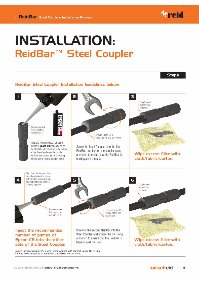
Inject the recommended number of pumps of Epcon C8 into the other side of the Steel Coupler.
Screw in the second ReidBar into the Steel Coupler, and tighten the bar using a wrench to ensure that the ReidBar is hard against the stop.
Wipe excess filler with cloth/fabric/carton.
4 5 6
| ReidBar Steel Couplers Installation Process
INSTALLATION: ReidBar™ Steel Coupler
Steps
Inject the recommended number of pumps of Epcon C8 into one side of the Steel Coupler. Start from the bottom of the thread and draw the nozzle out from the component in a rotating motion as the filler is being injected.
Screw the Steel Coupler onto the first ReidBar, and tighten the coupler using a wrench to ensure that the ReidBar is hard against the stop.
Wipe excess filler with cloth/fabric/carton.
1 2 3
ReidBar Steel Coupler Installation Guidelines below:
55
Recommended filler injection quantity pg 4.
Ensure Epcon C8 is visible at the end of Coupler.
Ensure Epcon C8 is visible at the end of Coupler.
Recommended filler injection quantity pg 4.
Coupler end excess filler removed.
Coupler end excess filler removed.
Ensure the appropriate PPE is worn when working with Ramset Epcon C8 XTREM. Refer to www.ramset.co.nz for Epcon C8 XTREM MSDS Sheet.
spec & install guide | reidbar steel components
Start from the bottom of the thread and draw the nozzle out from the component in a rotating motion as the filler is being injected.

| ReidBar™ Steel Flange Nut Specs
ReidBar™ Steel Flange Nut
6
Typical specification on drawings: “RB__FNS/FNSG + Ramset Epcon C8 XTREM”
Part No. Description Foot diameter (A) (mm)
Length (B) (mm)
Body Diameter (C) (mm)
RB12FNS 12mm ReidBar Steel Flange Nut 39 50 22
RBA16FNS 16mm ReidBar Steel Flange Nut 58 50 35
RB20FNS 20mm ReidBar Steel Flange Nut 67 50 35
RB25FNS 25mm ReidBar Steel Flange Nut 83 80 42
RB32FNS 32mm ReidBar Steel Flange Nut 92 95 55
RBA16FNSG* 16mm ReidBar Steel Flange Nut Galvanised 58 50 35
RB20FNSG* 20mm ReidBar Steel Flange Nut Galvanised 67 50 35
RB25FNSG* 25mm ReidBar Steel Flange Nut Galvanised 83 80 42
RB32FNSG* 32mm ReidBar Steel Flange Nut Galvanised 92 95 55
Installation
*Additional lead time apply for HDG products
Part No. No of Injections* Approx. Fittings/cartridge**
RB12FNS 3 30
RBA16FNS/FNSG 3 30
RB20FNS/FNSG 4 22
RB25FNS/FNSG 6 15
RB32FNS/FNSG 8 11
Recommended amount of Epcon C8 XTREM injections
*recommendations are based on the use of mixing nozzle type “ISNE”. Quantities based on full pumps. **Based on 90 pumps per Epcon C8 XTREM cartridge.
Product Specs
A
B
C
ReidBar Steel Couplers, Flange Nut and Threaded Inserts are to be installed utilising Ramset Epcon C8 XTREM.
spec & install guide | reidbar steel components
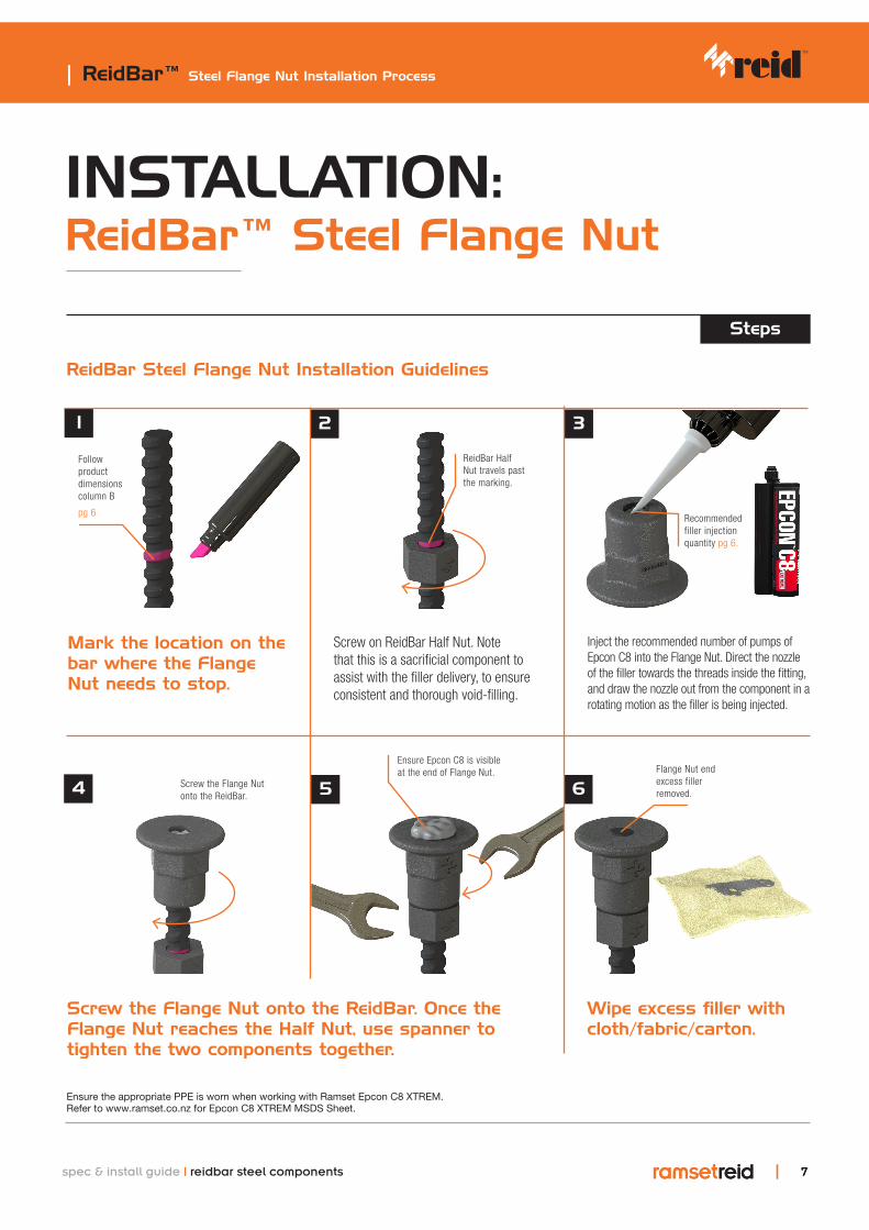
Screw the Flange Nut onto the ReidBar. Once the Flange Nut reaches the Half Nut, use spanner to tighten the two components together.
Wipe excess filler with cloth/fabric/carton.
4 6
| ReidBar™ Steel Flange Nut Installation Process
INSTALLATION: ReidBar™ Steel Flange Nut
Steps
Mark the location on the bar where the Flange Nut needs to stop.
Screw on ReidBar Half Nut. Note that this is a sacrificial component to assist with the filler delivery, to ensure consistent and thorough void-filling.
Inject the recommended number of pumps of Epcon C8 into the Flange Nut. Direct the nozzle of the filler towards the threads inside the fitting, and draw the nozzle out from the component in a rotating motion as the filler is being injected.
1 2 3
ReidBar Steel Flange Nut Installation Guidelines
77
5
Recommended filler injection quantity pg 6.
Ensure Epcon C8 is visible at the end of Flange Nut.
ReidBar Half Nut travels past the marking.
Follow product dimensions column B
pg 6
Flange Nut end excess filler removed.
Ensure the appropriate PPE is worn when working with Ramset Epcon C8 XTREM. Refer to www.ramset.co.nz for Epcon C8 XTREM MSDS Sheet.
Screw the Flange Nut onto the ReidBar.
spec & install guide | reidbar steel components
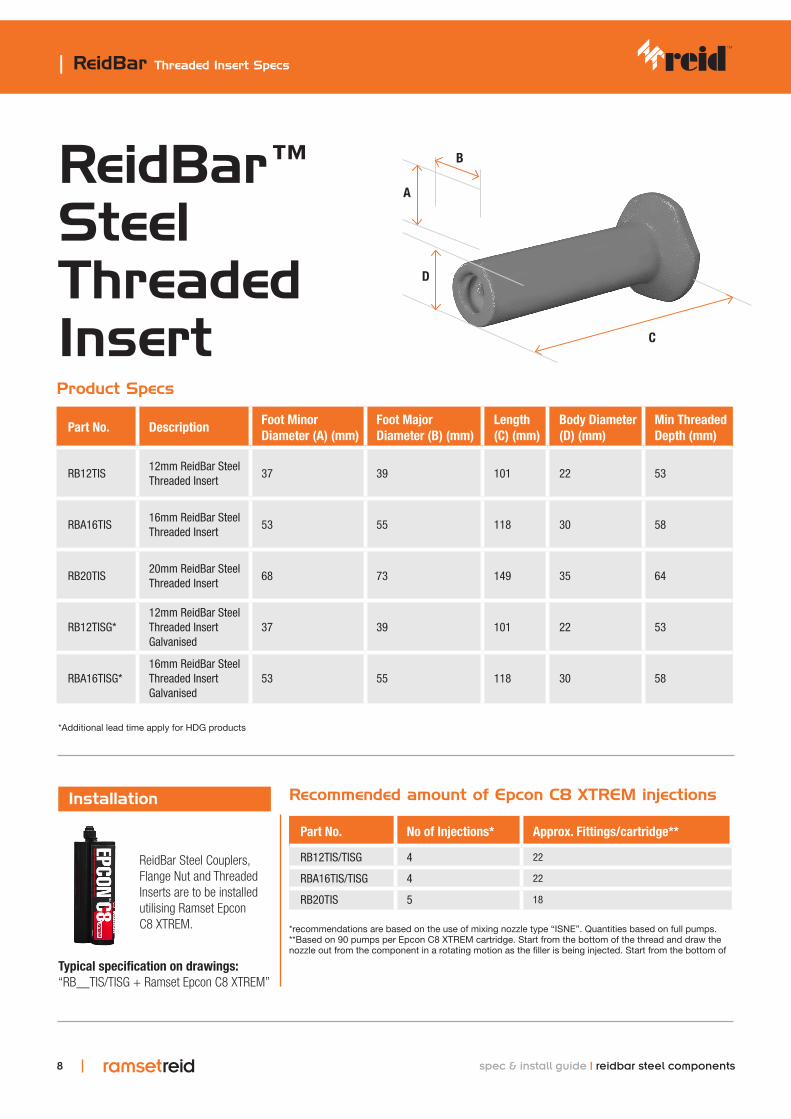
| ReidBar Threaded Insert Specs
ReidBar™ Steel Threaded Insert
8
Typical specification on drawings: “RB__TIS/TISG + Ramset Epcon C8 XTREM”
Part No. Description Foot Minor Diameter (A) (mm)
Foot Major Diameter (B) (mm)
Length (C) (mm)
Body Diameter (D) (mm)
Min Threaded Depth (mm)
RB12TIS12mm ReidBar Steel Threaded Insert
37 39 101 22 53
RBA16TIS16mm ReidBar Steel Threaded Insert
53 55 118 30 58
RB20TIS20mm ReidBar Steel Threaded Insert
68 73 149 35 64
RB12TISG*12mm ReidBar Steel Threaded Insert Galvanised
37 39 101 22 53
RBA16TISG*16mm ReidBar Steel Threaded Insert Galvanised
53 55 118 30 58
Installation
*Additional lead time apply for HDG products
Part No. No of Injections* Approx. Fittings/cartridge**
RB12TIS/TISG 4 22
RBA16TIS/TISG 4 22
RB20TIS 5 18
Recommended amount of Epcon C8 XTREM injections
*recommendations are based on the use of mixing nozzle type “ISNE”. Quantities based on full pumps. **Based on 90 pumps per Epcon C8 XTREM cartridge. Start from the bottom of the thread and draw the nozzle out from the component in a rotating motion as the filler is being injected. Start from the bottom of
Product Specs
C
D
A
B
ReidBar Steel Couplers, Flange Nut and Threaded Inserts are to be installed utilising Ramset Epcon C8 XTREM.
spec & install guide | reidbar steel components
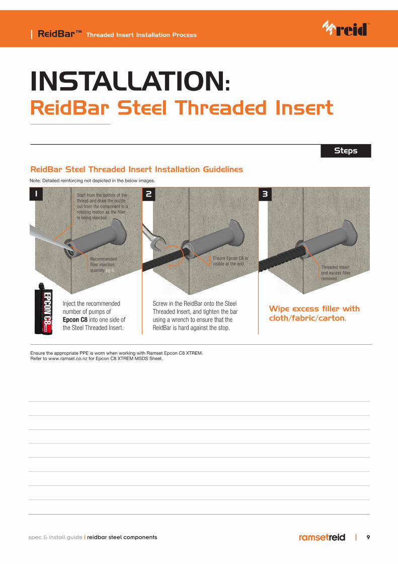
Threaded Insert end excess filler removed.
| ReidBar™ Threaded Insert Installation Process
INSTALLATION: ReidBar Steel Threaded Insert
Steps
ReidBar Steel Threaded Insert Installation Guidelines
99
Inject the recommended number of pumps of Epcon C8 into one side of the Steel Threaded Insert.
Wipe excess filler with cloth/fabric/carton.
1 2 3
Recommended filler injection quantity pg 8.
Ensure Epcon C8 is visible at the end.
Ensure the appropriate PPE is worn when working with Ramset Epcon C8 XTREM. Refer to www.ramset.co.nz for Epcon C8 XTREM MSDS Sheet.
Screw in the ReidBar onto the Steel Threaded Insert, and tighten the bar using a wrench to ensure that the ReidBar is hard against the stop.
Note: Detailed reinforcing not depicted in the below images.
spec & install guide | reidbar steel components
Start from the bottom of the thread and draw the nozzle out from the component in a rotating motion as the filler is being injected.
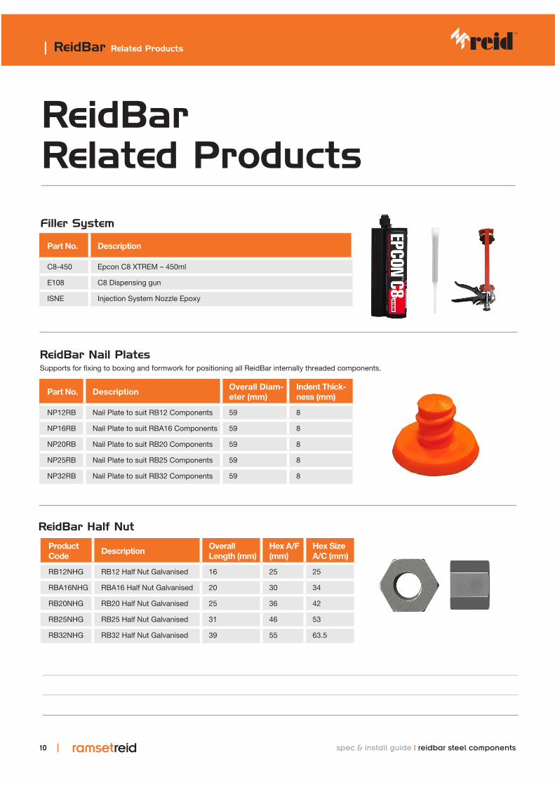
Product Code
DescriptionOverallLength (mm)
Hex A/F (mm)
Hex Size A/C (mm)
RB12NHG RB12 Half Nut Galvanised 16 25 25
RBA16NHG RBA16 Half Nut Galvanised 20 30 34
RB20NHG RB20 Half Nut Galvanised 25 36 42
RB25NHG RB25 Half Nut Galvanised 31 46 53
RB32NHG RB32 Half Nut Galvanised 39 55 63.5
Part No. Description
C8-450 Epcon C8 XTREM – 450ml
E108 C8 Dispensing gun
ISNE Injection System Nozzle Epoxy
| ReidBar Related Products
ReidBar Related Products
Part No. DescriptionOverall Diam-eter (mm)
Indent Thick-ness (mm)
NP12RB Nail Plate to suit RB12 Components 59 8
NP16RB Nail Plate to suit RBA16 Components 59 8
NP20RB Nail Plate to suit RB20 Components 59 8
NP25RB Nail Plate to suit RB25 Components 59 8
NP32RB Nail Plate to suit RB32 Components 59 8
ReidBar Nail PlatesSupports for fixing to boxing and formwork for positioning all ReidBar internally threaded components.
Filler System
ReidBar Half Nut
10 spec & install guide | reidbar steel components


customer serviceReid™ New Zealand Customer Service CentreTel: 0800 88 22 12 Email: [email protected]: www.reids.co.nz
ramsetreid™ 23-29 Poland Road, Glenfield, Auckland 0627 New ZealandIn the interests of product improvement, ramsetreid™ reserves the right to alter product specifications as required. Information included in this document is stated as at July 2019. Readers should contact ramsetreid™ or consult ramsetreid™ detailed technical information to ensure product is suitable for intended use prior to purchase. ramsetreid™, a division of ITW New Zealand © copyright 2019.™ Trademarks of Cetram Pty. Ltd. Used under license by ramsetreid™.