reinforced thermoset plastic corrosion-resistant equipment
TRANSCRIPT

ReinforcedThermoset Plastic Corrosion-Resistant Equipment
A N A M E R I C A N N A T I O N A L S T A N D A R D
ASME RTP-1–2017(Revision of ASME RTP-1–2015)

ASME RTP-1–2017(Revision of ASME RTP-1–2015)
ReinforcedThermoset PlasticCorrosion-ResistantEquipment
A N A M E R I C A N N A T I O N A L S T A N D A R D
Two Park Avenue • New York, NY • 10016 USA
Get more FREE standards from Standard Sharing Group and our chats

Date of Issuance: November 27, 2017
The next edition of this Standard is scheduled for publication in 2019. This Standard will becomeeffective 6 months after the Date of Issuance.
ASME issues written replies to inquiries concerning interpretations of technical aspects ofthis Standard. Periodically certain actions of the ASME RTP Committee may be published as Cases.Cases and interpretations are published on the ASME Web site under the Committee Pages athttp://cstools.asme.org/ as they are issued.
Errata to codes and standards may be posted on the ASME Web site under the Committee Pages toprovide corrections to incorrectly published items, or to correct typographical or grammatical errorsin codes and standards. Such errata shall be used on the date posted.
The Committee Pages can be found at http://cstools.asme.org/. There is an option available toautomatically receive an e-mail notification when errata are posted to a particular code or standard.This option can be found on the appropriate Committee Page after selecting “Errata” in the “PublicationInformation” section.
ASME is the registered trademark of The American Society of Mechanical Engineers.
This code or standard was developed under procedures accredited as meeting the criteria for American NationalStandards. The Standards Committee that approved the code or standard was balanced to assure that individuals fromcompetent and concerned interests have had an opportunity to participate. The proposed code or standard was madeavailable for public review and comment that provides an opportunity for additional public input from industry, academia,regulatory agencies, and the public-at-large.
ASME does not “approve,” “rate,” or “endorse” any item, construction, proprietary device, or activity.ASME does not take any position with respect to the validity of any patent rights asserted in connection with any
items mentioned in this document, and does not undertake to insure anyone utilizing a standard against liability forinfringement of any applicable letters patent, nor assume any such liability. Users of a code or standard are expresslyadvised that determination of the validity of any such patent rights, and the risk of infringement of such rights, isentirely their own responsibility.
Participation by federal agency representative(s) or person(s) affiliated with industry is not to be interpreted asgovernment or industry endorsement of this code or standard.
ASME accepts responsibility for only those interpretations of this document issued in accordance with the establishedASME procedures and policies, which precludes the issuance of interpretations by individuals.
No part of this document may be reproduced in any form,in an electronic retrieval system or otherwise,
without the prior written permission of the publisher.
The American Society of Mechanical EngineersTwo Park Avenue, New York, NY 10016-5990
Copyright © 2017 byTHE AMERICAN SOCIETY OF MECHANICAL ENGINEERS
All rights reservedPrinted in U.S.A.

CONTENTS
Foreword . . . . . . . . . . . . . . . . . . . . . . . . . . . . . . . . . . . . . . . . . . . . . . . . . . . . . . . . . . . . . . . . . . . . . . . . . . . . . . xStatement of Policy on the Use of Certification Marks and Code Authorization
in Advertising . . . . . . . . . . . . . . . . . . . . . . . . . . . . . . . . . . . . . . . . . . . . . . . . . . . . . . . . . . . . . . . . . . . . . . . xiStatement of Policy on the Use of ASME Marking to Identify Manufactured Items . . . . . . . xiCommittee Roster . . . . . . . . . . . . . . . . . . . . . . . . . . . . . . . . . . . . . . . . . . . . . . . . . . . . . . . . . . . . . . . . . . . . . xiiIntroduction . . . . . . . . . . . . . . . . . . . . . . . . . . . . . . . . . . . . . . . . . . . . . . . . . . . . . . . . . . . . . . . . . . . . . . . . . . . xivSummary of Changes . . . . . . . . . . . . . . . . . . . . . . . . . . . . . . . . . . . . . . . . . . . . . . . . . . . . . . . . . . . . . . . . . . xv
Part 1 General Requirements . . . . . . . . . . . . . . . . . . . . . . . . . . . . . . . . . . . . . . . . . . . . . . . . . . . . . 11-100 Introduction . . . . . . . . . . . . . . . . . . . . . . . . . . . . . . . . . . . . . . . . . . . . . . . . . . . . . . . . . . . . . . 11-200 User’s Basic Requirements Specification . . . . . . . . . . . . . . . . . . . . . . . . . . . . . . . . . . . 21-300 Fabricator’s Design Report . . . . . . . . . . . . . . . . . . . . . . . . . . . . . . . . . . . . . . . . . . . . . . . . 71-400 Inspection . . . . . . . . . . . . . . . . . . . . . . . . . . . . . . . . . . . . . . . . . . . . . . . . . . . . . . . . . . . . . . . . 71-500 Fabricator’s Quality Control Program . . . . . . . . . . . . . . . . . . . . . . . . . . . . . . . . . . . . . 8
Part 2 Materials. . . . . . . . . . . . . . . . . . . . . . . . . . . . . . . . . . . . . . . . . . . . . . . . . . . . . . . . . . . . . . . . . . 122-100 Scope . . . . . . . . . . . . . . . . . . . . . . . . . . . . . . . . . . . . . . . . . . . . . . . . . . . . . . . . . . . . . . . . . . . . 122-200 Laminate Compositions . . . . . . . . . . . . . . . . . . . . . . . . . . . . . . . . . . . . . . . . . . . . . . . . . . 122-300 Materials . . . . . . . . . . . . . . . . . . . . . . . . . . . . . . . . . . . . . . . . . . . . . . . . . . . . . . . . . . . . . . . . . 12Subpart 2A Requirements for Representative Flat Laminates . . . . . . . . . . . . . . . . . . . . . . . . . . . 132A-100 Introduction . . . . . . . . . . . . . . . . . . . . . . . . . . . . . . . . . . . . . . . . . . . . . . . . . . . . . . . . . . . . . . 132A-200 Laminate Requirements . . . . . . . . . . . . . . . . . . . . . . . . . . . . . . . . . . . . . . . . . . . . . . . . . . 132A-300 Requirements for Physical and Mechanical Properties . . . . . . . . . . . . . . . . . . . . . 162A-400 Test Methods . . . . . . . . . . . . . . . . . . . . . . . . . . . . . . . . . . . . . . . . . . . . . . . . . . . . . . . . . . . . . 172A-500 Records . . . . . . . . . . . . . . . . . . . . . . . . . . . . . . . . . . . . . . . . . . . . . . . . . . . . . . . . . . . . . . . . . . 172A-600 Additional Standard Laminate Compositions for Subpart 2A . . . . . . . . . . . . . . 17Subpart 2B Requirements for Laminates Developed Using the Lamination Analysis
Method (Type X) . . . . . . . . . . . . . . . . . . . . . . . . . . . . . . . . . . . . . . . . . . . . . . . . . . . . . . . 172B-100 Laminate Composition . . . . . . . . . . . . . . . . . . . . . . . . . . . . . . . . . . . . . . . . . . . . . . . . . . . 172B-200 Requirements for Physical and Mechanical Properties . . . . . . . . . . . . . . . . . . . . . 182B-300 Test Methods . . . . . . . . . . . . . . . . . . . . . . . . . . . . . . . . . . . . . . . . . . . . . . . . . . . . . . . . . . . . . 182B-400 Records . . . . . . . . . . . . . . . . . . . . . . . . . . . . . . . . . . . . . . . . . . . . . . . . . . . . . . . . . . . . . . . . . . 18Subpart 2C Permissible Tolerances for Laminate Thickness Variation . . . . . . . . . . . . . . . . . . 182C-100 Tolerance for Average Spot Thickness . . . . . . . . . . . . . . . . . . . . . . . . . . . . . . . . . . . . . 182C-200 Tolerance for Average Thickness of a Major Part . . . . . . . . . . . . . . . . . . . . . . . . . . 182C-300 Exceptions and Adjustments . . . . . . . . . . . . . . . . . . . . . . . . . . . . . . . . . . . . . . . . . . . . . . 18
Part 3 Design . . . . . . . . . . . . . . . . . . . . . . . . . . . . . . . . . . . . . . . . . . . . . . . . . . . . . . . . . . . . . . . . . . . . 193-100 Scope . . . . . . . . . . . . . . . . . . . . . . . . . . . . . . . . . . . . . . . . . . . . . . . . . . . . . . . . . . . . . . . . . . . . 193-200 General . . . . . . . . . . . . . . . . . . . . . . . . . . . . . . . . . . . . . . . . . . . . . . . . . . . . . . . . . . . . . . . . . . 193-300 Definitions . . . . . . . . . . . . . . . . . . . . . . . . . . . . . . . . . . . . . . . . . . . . . . . . . . . . . . . . . . . . . . . 19Subpart 3A Design by Rules . . . . . . . . . . . . . . . . . . . . . . . . . . . . . . . . . . . . . . . . . . . . . . . . . . . . . . . . . . 203A-100 Loadings . . . . . . . . . . . . . . . . . . . . . . . . . . . . . . . . . . . . . . . . . . . . . . . . . . . . . . . . . . . . . . . . . 203A-200 Design for Total Internal Pressure . . . . . . . . . . . . . . . . . . . . . . . . . . . . . . . . . . . . . . . . . 213A-300 Design for External Pressure . . . . . . . . . . . . . . . . . . . . . . . . . . . . . . . . . . . . . . . . . . . . . . 243A-400 Seismic, Wind, and Snow Loadings . . . . . . . . . . . . . . . . . . . . . . . . . . . . . . . . . . . . . . . 273A-500 Large Diameter RTP Equipment Body Flanges . . . . . . . . . . . . . . . . . . . . . . . . . . . . 283A-600 Vessels Supported by Shell Attachments . . . . . . . . . . . . . . . . . . . . . . . . . . . . . . . . . . 283A-700 Reinforcement of Circular Openings . . . . . . . . . . . . . . . . . . . . . . . . . . . . . . . . . . . . . . 283A-800 Secondary Bond Shear Stress . . . . . . . . . . . . . . . . . . . . . . . . . . . . . . . . . . . . . . . . . . . . . 29
iii
Get more FREE standards from Standard Sharing Group and our chats

Subpart 3B Design by Stress Analysis . . . . . . . . . . . . . . . . . . . . . . . . . . . . . . . . . . . . . . . . . . . . . . . . 293B-100 Introduction . . . . . . . . . . . . . . . . . . . . . . . . . . . . . . . . . . . . . . . . . . . . . . . . . . . . . . . . . . . . . . 293B-200 Design Acceptability . . . . . . . . . . . . . . . . . . . . . . . . . . . . . . . . . . . . . . . . . . . . . . . . . . . . . 303B-300 Loading . . . . . . . . . . . . . . . . . . . . . . . . . . . . . . . . . . . . . . . . . . . . . . . . . . . . . . . . . . . . . . . . . . 313B-400 Design . . . . . . . . . . . . . . . . . . . . . . . . . . . . . . . . . . . . . . . . . . . . . . . . . . . . . . . . . . . . . . . . . . . 313B-500 Stress Criteria . . . . . . . . . . . . . . . . . . . . . . . . . . . . . . . . . . . . . . . . . . . . . . . . . . . . . . . . . . . . 313B-600 External Pressure . . . . . . . . . . . . . . . . . . . . . . . . . . . . . . . . . . . . . . . . . . . . . . . . . . . . . . . . . 323B-700 Attachments . . . . . . . . . . . . . . . . . . . . . . . . . . . . . . . . . . . . . . . . . . . . . . . . . . . . . . . . . . . . . 32
Part 4 Fabrication . . . . . . . . . . . . . . . . . . . . . . . . . . . . . . . . . . . . . . . . . . . . . . . . . . . . . . . . . . . . . . . . 334-100 Scope . . . . . . . . . . . . . . . . . . . . . . . . . . . . . . . . . . . . . . . . . . . . . . . . . . . . . . . . . . . . . . . . . . . . 334-200 Large Diameter Body Flanges . . . . . . . . . . . . . . . . . . . . . . . . . . . . . . . . . . . . . . . . . . . . . 334-300 Shell Joints . . . . . . . . . . . . . . . . . . . . . . . . . . . . . . . . . . . . . . . . . . . . . . . . . . . . . . . . . . . . . . . 334-400 Flanged Nozzles . . . . . . . . . . . . . . . . . . . . . . . . . . . . . . . . . . . . . . . . . . . . . . . . . . . . . . . . . 344-500 Manways . . . . . . . . . . . . . . . . . . . . . . . . . . . . . . . . . . . . . . . . . . . . . . . . . . . . . . . . . . . . . . . . 354-600 Reinforcement of Cutouts . . . . . . . . . . . . . . . . . . . . . . . . . . . . . . . . . . . . . . . . . . . . . . . . . 354-700 Tolerances . . . . . . . . . . . . . . . . . . . . . . . . . . . . . . . . . . . . . . . . . . . . . . . . . . . . . . . . . . . . . . . 354-800 Balsa Wood Cored Plates . . . . . . . . . . . . . . . . . . . . . . . . . . . . . . . . . . . . . . . . . . . . . . . . . 35
Part 5 Overpressure Protection. . . . . . . . . . . . . . . . . . . . . . . . . . . . . . . . . . . . . . . . . . . . . . . . . . . . 525-100 Basis for Design . . . . . . . . . . . . . . . . . . . . . . . . . . . . . . . . . . . . . . . . . . . . . . . . . . . . . . . . . . 525-200 Protection Against Overpressure . . . . . . . . . . . . . . . . . . . . . . . . . . . . . . . . . . . . . . . . . . 525-300 Type of Overpressure Protection . . . . . . . . . . . . . . . . . . . . . . . . . . . . . . . . . . . . . . . . . . 525-400 Location of Overpressure Protection Devices . . . . . . . . . . . . . . . . . . . . . . . . . . . . . . 525-500 Installation Practices . . . . . . . . . . . . . . . . . . . . . . . . . . . . . . . . . . . . . . . . . . . . . . . . . . . . . 525-600 Overpressure Device Set Pressure . . . . . . . . . . . . . . . . . . . . . . . . . . . . . . . . . . . . . . . . . 525-700 Relief Device Sizing . . . . . . . . . . . . . . . . . . . . . . . . . . . . . . . . . . . . . . . . . . . . . . . . . . . . . . 525-800 Discharge Lines From Pressure Relief Devices . . . . . . . . . . . . . . . . . . . . . . . . . . . . . 525-900 Responsibility for Design and Selection . . . . . . . . . . . . . . . . . . . . . . . . . . . . . . . . . . . 53
Part 6 Inspection and Tests . . . . . . . . . . . . . . . . . . . . . . . . . . . . . . . . . . . . . . . . . . . . . . . . . . . . . . . 546-100 Scope . . . . . . . . . . . . . . . . . . . . . . . . . . . . . . . . . . . . . . . . . . . . . . . . . . . . . . . . . . . . . . . . . . . . 546-200 Inspector . . . . . . . . . . . . . . . . . . . . . . . . . . . . . . . . . . . . . . . . . . . . . . . . . . . . . . . . . . . . . . . . . 546-300 Inspection and Responsibility . . . . . . . . . . . . . . . . . . . . . . . . . . . . . . . . . . . . . . . . . . . . . 546-400 Conditions for Inspection . . . . . . . . . . . . . . . . . . . . . . . . . . . . . . . . . . . . . . . . . . . . . . . . . 546-500 Equipment Design . . . . . . . . . . . . . . . . . . . . . . . . . . . . . . . . . . . . . . . . . . . . . . . . . . . . . . . 556-600 Materials . . . . . . . . . . . . . . . . . . . . . . . . . . . . . . . . . . . . . . . . . . . . . . . . . . . . . . . . . . . . . . . . . 556-700 Fabrication . . . . . . . . . . . . . . . . . . . . . . . . . . . . . . . . . . . . . . . . . . . . . . . . . . . . . . . . . . . . . . . 556-800 Fabricator’s Quality Assurance Program . . . . . . . . . . . . . . . . . . . . . . . . . . . . . . . . . . 556-900 Final Inspection . . . . . . . . . . . . . . . . . . . . . . . . . . . . . . . . . . . . . . . . . . . . . . . . . . . . . . . . . . 55
Part 7 Shop Qualification . . . . . . . . . . . . . . . . . . . . . . . . . . . . . . . . . . . . . . . . . . . . . . . . . . . . . . . . . 647-100 Scope . . . . . . . . . . . . . . . . . . . . . . . . . . . . . . . . . . . . . . . . . . . . . . . . . . . . . . . . . . . . . . . . . . . . 647-200 General . . . . . . . . . . . . . . . . . . . . . . . . . . . . . . . . . . . . . . . . . . . . . . . . . . . . . . . . . . . . . . . . . . 647-300 Fabricator’s Facilities and Equipment . . . . . . . . . . . . . . . . . . . . . . . . . . . . . . . . . . . . . 647-400 Personnel . . . . . . . . . . . . . . . . . . . . . . . . . . . . . . . . . . . . . . . . . . . . . . . . . . . . . . . . . . . . . . . . 647-500 Quality Control Program, Document Handling, and Record System . . . . . . . . 647-600 Demonstration of Capability (Demonstration Laminates) . . . . . . . . . . . . . . . . . . 647-700 Minimum Test Values From Demonstration Laminates . . . . . . . . . . . . . . . . . . . . 677-800 Demonstration Vessel . . . . . . . . . . . . . . . . . . . . . . . . . . . . . . . . . . . . . . . . . . . . . . . . . . . . 677-900 Identifying Demonstration Laminates . . . . . . . . . . . . . . . . . . . . . . . . . . . . . . . . . . . . . 687-1000 Laboratory Test and Test Report Requirements for Demonstration
Laminates . . . . . . . . . . . . . . . . . . . . . . . . . . . . . . . . . . . . . . . . . . . . . . . . . . . . . . . . . . . . . 68
iv

Part 8 Certification . . . . . . . . . . . . . . . . . . . . . . . . . . . . . . . . . . . . . . . . . . . . . . . . . . . . . . . . . . . . . . . 708-100 Scope . . . . . . . . . . . . . . . . . . . . . . . . . . . . . . . . . . . . . . . . . . . . . . . . . . . . . . . . . . . . . . . . . . . . 708-200 General . . . . . . . . . . . . . . . . . . . . . . . . . . . . . . . . . . . . . . . . . . . . . . . . . . . . . . . . . . . . . . . . . . 708-300 Certification Process . . . . . . . . . . . . . . . . . . . . . . . . . . . . . . . . . . . . . . . . . . . . . . . . . . . . . . 708-400 ASME RTP-1 Certificate of Authorization Holder . . . . . . . . . . . . . . . . . . . . . . . . . . 708-500 Issuance of Certification . . . . . . . . . . . . . . . . . . . . . . . . . . . . . . . . . . . . . . . . . . . . . . . . . . 708-600 Designated Oversight . . . . . . . . . . . . . . . . . . . . . . . . . . . . . . . . . . . . . . . . . . . . . . . . . . . . 718-700 Data Reports . . . . . . . . . . . . . . . . . . . . . . . . . . . . . . . . . . . . . . . . . . . . . . . . . . . . . . . . . . . . . 718-800 ASME RTP Certified Mark and Certified Designator . . . . . . . . . . . . . . . . . . . . . . 71
Figures3-1 Toriconical Head Dimensions . . . . . . . . . . . . . . . . . . . . . . . . . . . . . . . . . . . . . . . . . . . . . 233-2 Toriconical Head Dimensions for External Pressure . . . . . . . . . . . . . . . . . . . . . . . . 274-1 Torispherical Heads . . . . . . . . . . . . . . . . . . . . . . . . . . . . . . . . . . . . . . . . . . . . . . . . . . . . . . 364-2 Flat-Bottom Tank Knuckle Detail . . . . . . . . . . . . . . . . . . . . . . . . . . . . . . . . . . . . . . . . . . 374-3 Joint Arrangement . . . . . . . . . . . . . . . . . . . . . . . . . . . . . . . . . . . . . . . . . . . . . . . . . . . . . . . . 394-4 Flush Nozzle Installation . . . . . . . . . . . . . . . . . . . . . . . . . . . . . . . . . . . . . . . . . . . . . . . . . 404-5 Penetrating Nozzle Installation . . . . . . . . . . . . . . . . . . . . . . . . . . . . . . . . . . . . . . . . . . . 414-6 Bottom Drain Detail . . . . . . . . . . . . . . . . . . . . . . . . . . . . . . . . . . . . . . . . . . . . . . . . . . . . . . 424-7 Stiffener Details for Half-Round, Trapezoidal, and Filament Wound Band
Configurations . . . . . . . . . . . . . . . . . . . . . . . . . . . . . . . . . . . . . . . . . . . . . . . . . . . . . . . . . 434-8 Support Skirt Attachment Detail . . . . . . . . . . . . . . . . . . . . . . . . . . . . . . . . . . . . . . . . . . 444-9 Fabrication Tolerances . . . . . . . . . . . . . . . . . . . . . . . . . . . . . . . . . . . . . . . . . . . . . . . . . . . . 454-10 Nozzle Flange Dimensions for Class 150 Bolting . . . . . . . . . . . . . . . . . . . . . . . . . . 464-11 Flanged Nozzle Lay-Up Method . . . . . . . . . . . . . . . . . . . . . . . . . . . . . . . . . . . . . . . . . . 474-12 Nozzle Installation and Cutout Reinforcement Location Alternate . . . . . . . . . 484-13 Nozzle Gussets . . . . . . . . . . . . . . . . . . . . . . . . . . . . . . . . . . . . . . . . . . . . . . . . . . . . . . . . . . . 494-14 Flange Tolerances . . . . . . . . . . . . . . . . . . . . . . . . . . . . . . . . . . . . . . . . . . . . . . . . . . . . . . . . 504-15 Flat Cored Bottom Knuckle Detail . . . . . . . . . . . . . . . . . . . . . . . . . . . . . . . . . . . . . . . . 507-1 Dimensions for Tensile Test Specimen . . . . . . . . . . . . . . . . . . . . . . . . . . . . . . . . . . . . . 698-1 Official ASME Certification Mark With RTP Designator . . . . . . . . . . . . . . . . . . . 71
Tables1-1 User’s Basic Requirements Specification (UBRS) . . . . . . . . . . . . . . . . . . . . . . . . . . . 31-2 Fabricator’s Data Report . . . . . . . . . . . . . . . . . . . . . . . . . . . . . . . . . . . . . . . . . . . . . . . . . . 91-3 Fabricator’s Partial Data Report . . . . . . . . . . . . . . . . . . . . . . . . . . . . . . . . . . . . . . . . . . . 112A-1 Standard Laminate Composition Type I . . . . . . . . . . . . . . . . . . . . . . . . . . . . . . . . . . . 142A-2 Standard Laminate Composition Type II . . . . . . . . . . . . . . . . . . . . . . . . . . . . . . . . . . 152A-3 Minimum Values of Flat Laminates . . . . . . . . . . . . . . . . . . . . . . . . . . . . . . . . . . . . . . . 164-1 Flange Flatness Tolerance . . . . . . . . . . . . . . . . . . . . . . . . . . . . . . . . . . . . . . . . . . . . . . . . . 514-2 Typical Dimensions of Manways . . . . . . . . . . . . . . . . . . . . . . . . . . . . . . . . . . . . . . . . . . 514-3 Shear Bond Length . . . . . . . . . . . . . . . . . . . . . . . . . . . . . . . . . . . . . . . . . . . . . . . . . . . . . . . 516-1 RTP Visual Inspection Acceptance Criteria . . . . . . . . . . . . . . . . . . . . . . . . . . . . . . . . 597-1 Required Resins and Acceptable Fabrication Processes for Demonstration
Laminates . . . . . . . . . . . . . . . . . . . . . . . . . . . . . . . . . . . . . . . . . . . . . . . . . . . . . . . . . . . . . 657-2 Dimensional Requirements for Hand Lay-Up and Spray-Up Demonstration
Laminates . . . . . . . . . . . . . . . . . . . . . . . . . . . . . . . . . . . . . . . . . . . . . . . . . . . . . . . . . . . . . 667-3 Reinforcement Requirements for Hand Lay-Up and Spray-Up
Demonstration Laminates . . . . . . . . . . . . . . . . . . . . . . . . . . . . . . . . . . . . . . . . . . . . . . 66
Mandatory AppendicesM-1 Reinforcement Materials Receiving Procedures . . . . . . . . . . . . . . . . . . . . . . . . . . . . 73M-2 Matrix Materials Receiving Procedures . . . . . . . . . . . . . . . . . . . . . . . . . . . . . . . . . . . . 82M-3 Calculations Using the Classical Lamination Theory (CLT) Analysis
Method . . . . . . . . . . . . . . . . . . . . . . . . . . . . . . . . . . . . . . . . . . . . . . . . . . . . . . . . . . . . . . . . 89M-4 Quality Control Program . . . . . . . . . . . . . . . . . . . . . . . . . . . . . . . . . . . . . . . . . . . . . . . . . 112M-5 Qualification of Laminators and Secondary Bonders . . . . . . . . . . . . . . . . . . . . . . . 114M-6 Demonstration Vessel . . . . . . . . . . . . . . . . . . . . . . . . . . . . . . . . . . . . . . . . . . . . . . . . . . . . 121
v
Get more FREE standards from Standard Sharing Group and our chats

M-7 Repair Procedures . . . . . . . . . . . . . . . . . . . . . . . . . . . . . . . . . . . . . . . . . . . . . . . . . . . . . . . . 129M-8 Acoustic Emission Examination . . . . . . . . . . . . . . . . . . . . . . . . . . . . . . . . . . . . . . . . . . . 134M-9 Glossary . . . . . . . . . . . . . . . . . . . . . . . . . . . . . . . . . . . . . . . . . . . . . . . . . . . . . . . . . . . . . . . . . 136M-10 Reference Documents . . . . . . . . . . . . . . . . . . . . . . . . . . . . . . . . . . . . . . . . . . . . . . . . . . . . . 140M-11 Submittal of Technical Inquiries to the Reinforced Thermoset Plastic
Corrosion-Resistant Equipment Committee . . . . . . . . . . . . . . . . . . . . . . . . . . . . . 143M-12 Dual Laminate Vessels . . . . . . . . . . . . . . . . . . . . . . . . . . . . . . . . . . . . . . . . . . . . . . . . . . . 145M-13 Balsa Wood Receiving and Inspection Procedures . . . . . . . . . . . . . . . . . . . . . . . . . 182
FiguresM3-1 Moment Resultants . . . . . . . . . . . . . . . . . . . . . . . . . . . . . . . . . . . . . . . . . . . . . . . . . . . . . . . 91M3-2 Force Resultants . . . . . . . . . . . . . . . . . . . . . . . . . . . . . . . . . . . . . . . . . . . . . . . . . . . . . . . . . . 91M3-3 Geometry and Notation for an n-Layered Laminate . . . . . . . . . . . . . . . . . . . . . . . 91M3-4 Coordinate Systems . . . . . . . . . . . . . . . . . . . . . . . . . . . . . . . . . . . . . . . . . . . . . . . . . . . . . . 92M5-1 Pipe Test Piece . . . . . . . . . . . . . . . . . . . . . . . . . . . . . . . . . . . . . . . . . . . . . . . . . . . . . . . . . . . 117M5-2 Secondary Bond Test Assembly . . . . . . . . . . . . . . . . . . . . . . . . . . . . . . . . . . . . . . . . . . . 118M5-3 Secondary Bond Test Specimen . . . . . . . . . . . . . . . . . . . . . . . . . . . . . . . . . . . . . . . . . . . 119M6-1 ASME RTP-1 Demonstration Vessel . . . . . . . . . . . . . . . . . . . . . . . . . . . . . . . . . . . . . . . 126M6-2 Post-Test Sectioning of Vessel for Final Inspection and Display . . . . . . . . . . . . 127M6-3 Witness of Hydrotest of ASME RTP-1 Demonstration Vessel (Attachment
No. 3) . . . . . . . . . . . . . . . . . . . . . . . . . . . . . . . . . . . . . . . . . . . . . . . . . . . . . . . . . . . . . . . . . 128M12C-1 Support Ledges Showing Recommended Weld Locations Away From
Thermoformed Bends . . . . . . . . . . . . . . . . . . . . . . . . . . . . . . . . . . . . . . . . . . . . . . . . . . 159M12D-1 Maximum Offset Allowed for Joints Between Sheets With Different
Thicknesses . . . . . . . . . . . . . . . . . . . . . . . . . . . . . . . . . . . . . . . . . . . . . . . . . . . . . . . . . . . . 161M12D-2 Visual Features of Hot Gas Welds . . . . . . . . . . . . . . . . . . . . . . . . . . . . . . . . . . . . . . . . . 163M12D-3 Illustrations of Flow Lines . . . . . . . . . . . . . . . . . . . . . . . . . . . . . . . . . . . . . . . . . . . . . . . . 163M12D-4 Heat-Affected Zone Patterns . . . . . . . . . . . . . . . . . . . . . . . . . . . . . . . . . . . . . . . . . . . . . . 164M12D-5 Butt Fusion Welds Showing Melt Flow Lines . . . . . . . . . . . . . . . . . . . . . . . . . . . . . . 164M12D-6 Nozzle Construction for Penetrating Nozzle . . . . . . . . . . . . . . . . . . . . . . . . . . . . . . . 166M12D-7 Nozzle and Manway Constructions . . . . . . . . . . . . . . . . . . . . . . . . . . . . . . . . . . . . . . . 167M12D-8 Bottom Nozzle Constructions . . . . . . . . . . . . . . . . . . . . . . . . . . . . . . . . . . . . . . . . . . . . . 168M12G-1 Dual Laminate Demonstration Vessel . . . . . . . . . . . . . . . . . . . . . . . . . . . . . . . . . . . . . 173M12G-2 Post-Test Sectioning of Dual Laminate Demonstration Vessel for Final
Inspection and Display . . . . . . . . . . . . . . . . . . . . . . . . . . . . . . . . . . . . . . . . . . . . . . . . . 178
TablesM1A-1 Veil and Mat Reinforcement Log Sheet . . . . . . . . . . . . . . . . . . . . . . . . . . . . . . . . . . . . 74M1B-1 Roving Reinforcement Log Sheet . . . . . . . . . . . . . . . . . . . . . . . . . . . . . . . . . . . . . . . . . . 76M1C-1 Fabric Reinforcement Log Sheet . . . . . . . . . . . . . . . . . . . . . . . . . . . . . . . . . . . . . . . . . . . 78M1D-1 Milled Fiber Reinforcement Log Sheet . . . . . . . . . . . . . . . . . . . . . . . . . . . . . . . . . . . . . 81M2E-1 Resin Log Sheet . . . . . . . . . . . . . . . . . . . . . . . . . . . . . . . . . . . . . . . . . . . . . . . . . . . . . . . . . . 86M2E-2 Curing Agents Log Sheet . . . . . . . . . . . . . . . . . . . . . . . . . . . . . . . . . . . . . . . . . . . . . . . . . 87M2F-1 Common Additives Log Sheet . . . . . . . . . . . . . . . . . . . . . . . . . . . . . . . . . . . . . . . . . . . . 88M3-1 Properties for Materials in the Design Example . . . . . . . . . . . . . . . . . . . . . . . . . . . 106M3-2 Lamina Input for CLT Calculations . . . . . . . . . . . . . . . . . . . . . . . . . . . . . . . . . . . . . . . 107M3-3 Stresses, Strains, and Strength Ratios . . . . . . . . . . . . . . . . . . . . . . . . . . . . . . . . . . . . . . 109M3-4 Woven Roving Layer Modeled as a Balanced and Symmetric Three-Ply
Laminate . . . . . . . . . . . . . . . . . . . . . . . . . . . . . . . . . . . . . . . . . . . . . . . . . . . . . . . . . . . . . . 110M5-1 Laminator Qualification Report . . . . . . . . . . . . . . . . . . . . . . . . . . . . . . . . . . . . . . . . . . . 115M5-2 Secondary Bonder Qualification Report . . . . . . . . . . . . . . . . . . . . . . . . . . . . . . . . . . . 116M6-1 User’s Basic Requirements Specification (UBRS) . . . . . . . . . . . . . . . . . . . . . . . . . . . 122M8-1 Acceptance Criteria Per Channel . . . . . . . . . . . . . . . . . . . . . . . . . . . . . . . . . . . . . . . . . . 134M12B-1 ASTM Specifications for Thermoplastic Polymers . . . . . . . . . . . . . . . . . . . . . . . . . . 146M12B-2 Typical Thermoplastic Polymer Properties . . . . . . . . . . . . . . . . . . . . . . . . . . . . . . . . . 147M12B-3 Thermoplastic Sheet or Roll Receiving Log . . . . . . . . . . . . . . . . . . . . . . . . . . . . . . . . 149M12B-4 Thermoplastic Sheet Visual Inspection Acceptance Criteria . . . . . . . . . . . . . . . . 150M12B-5 Welding Material Receiving Log . . . . . . . . . . . . . . . . . . . . . . . . . . . . . . . . . . . . . . . . . . 152
vi
M12B-6 Bonding Resin Receiving Log . . . . . . . . . . . . . . . . . . . . . . . . . . . . . . . . . . . . . . . . . . . . . 153M12B-7 Conductive Material Receiving Log . . . . . . . . . . . . . . . . . . . . . . . . . . . . . . . . . . . . . . . 155M12B-8 Thermoplastic Shape Receiving Log . . . . . . . . . . . . . . . . . . . . . . . . . . . . . . . . . . . . . . 157M12D-1 Visual Weld Defects . . . . . . . . . . . . . . . . . . . . . . . . . . . . . . . . . . . . . . . . . . . . . . . . . . . . . . 162M12E-1 Lining Visual Inspection Acceptance Criteria . . . . . . . . . . . . . . . . . . . . . . . . . . . . . . 171M12G-1 User’s Basic Requirements Specification (UBRS) . . . . . . . . . . . . . . . . . . . . . . . . . . . 174M12H-1 Weld Strength Requirements . . . . . . . . . . . . . . . . . . . . . . . . . . . . . . . . . . . . . . . . . . . . . . 180M13-1 Balsa Wood Core Inspection Sheet . . . . . . . . . . . . . . . . . . . . . . . . . . . . . . . . . . . . . . . . 183
Nonmandatory AppendicesNM-1 Design Examples . . . . . . . . . . . . . . . . . . . . . . . . . . . . . . . . . . . . . . . . . . . . . . . . . . . . . . . . . 184NM-2 Design of Integral Body Flanges . . . . . . . . . . . . . . . . . . . . . . . . . . . . . . . . . . . . . . . . . . 203NM-3 Seismic, Wind, and Snow Loadings . . . . . . . . . . . . . . . . . . . . . . . . . . . . . . . . . . . . . . . 219NM-4 Hold-Down Lug Design . . . . . . . . . . . . . . . . . . . . . . . . . . . . . . . . . . . . . . . . . . . . . . . . . . 226NM-5 Ring Support of Vessels . . . . . . . . . . . . . . . . . . . . . . . . . . . . . . . . . . . . . . . . . . . . . . . . . . 236NM-6 Example of a Fabricator’s Quality Control Program . . . . . . . . . . . . . . . . . . . . . . . . 250NM-7 Acceptance Inspection by User’s Inspector . . . . . . . . . . . . . . . . . . . . . . . . . . . . . . . . 264NM-8 Handling and Shipping . . . . . . . . . . . . . . . . . . . . . . . . . . . . . . . . . . . . . . . . . . . . . . . . . . 271NM-9 Installation of RTP Vessels . . . . . . . . . . . . . . . . . . . . . . . . . . . . . . . . . . . . . . . . . . . . . . . . 273NM-10 Requirements and Responsibilities of User (or User’s Agent), Fabricator,
Inspector, and Certified Individual . . . . . . . . . . . . . . . . . . . . . . . . . . . . . . . . . . . . . . 276NM-11 Design for 250-lb Concentrated Load on a Torispherical Head . . . . . . . . . . . . . 280NM-12 FRP Flange Design . . . . . . . . . . . . . . . . . . . . . . . . . . . . . . . . . . . . . . . . . . . . . . . . . . . . . . . 282NM-13 Stress Analysis Methods . . . . . . . . . . . . . . . . . . . . . . . . . . . . . . . . . . . . . . . . . . . . . . . . . . 286NM-15 Flat Cored Plate Design . . . . . . . . . . . . . . . . . . . . . . . . . . . . . . . . . . . . . . . . . . . . . . . . . . 308NM-16 External Pressure Design Example for Cylindrical Shells . . . . . . . . . . . . . . . . . . . 311NM-17 Stiffener Design Calculations . . . . . . . . . . . . . . . . . . . . . . . . . . . . . . . . . . . . . . . . . . . . . 314
FiguresNM1-1 Toriconical Head . . . . . . . . . . . . . . . . . . . . . . . . . . . . . . . . . . . . . . . . . . . . . . . . . . . . . . . . . 185NM1-2 Stress Intensity in a Toriconical Head . . . . . . . . . . . . . . . . . . . . . . . . . . . . . . . . . . . . . 187NM1-3 Horizontal Tank . . . . . . . . . . . . . . . . . . . . . . . . . . . . . . . . . . . . . . . . . . . . . . . . . . . . . . . . . . 189NM1-4 Pressure Distribution . . . . . . . . . . . . . . . . . . . . . . . . . . . . . . . . . . . . . . . . . . . . . . . . . . . . . 190NM1-5 Saddle Reaction . . . . . . . . . . . . . . . . . . . . . . . . . . . . . . . . . . . . . . . . . . . . . . . . . . . . . . . . . . 191NM1-6 Stress Along Top Meridian, Initial Try . . . . . . . . . . . . . . . . . . . . . . . . . . . . . . . . . . . . 192NM1-7 Stress Along 45-deg Meridian, Initial Try . . . . . . . . . . . . . . . . . . . . . . . . . . . . . . . . . . 193NM1-8 Stress Along 90-deg Meridian, Initial Try . . . . . . . . . . . . . . . . . . . . . . . . . . . . . . . . . . 194NM1-9 Stress Along 135-deg Meridian, Initial Try . . . . . . . . . . . . . . . . . . . . . . . . . . . . . . . . . 195NM1-10 Stress Along Bottom Meridian, Initial Try . . . . . . . . . . . . . . . . . . . . . . . . . . . . . . . . . 196NM1-11 Stress Along Top Meridian, Final Try . . . . . . . . . . . . . . . . . . . . . . . . . . . . . . . . . . . . . 198NM1-12 Stress Along 45-deg Meridian, Final Try . . . . . . . . . . . . . . . . . . . . . . . . . . . . . . . . . . 199NM1-13 Stress Along 90-deg Meridian, Final Try . . . . . . . . . . . . . . . . . . . . . . . . . . . . . . . . . . 200NM1-14 Stress Along 135-deg Meridian, Final Try . . . . . . . . . . . . . . . . . . . . . . . . . . . . . . . . . 201NM1-15 Stress Along Bottom Meridian, Final Try . . . . . . . . . . . . . . . . . . . . . . . . . . . . . . . . . . 202NM2-1 Design of Flat-Face Integral Body Flanges With Full-Face Gaskets . . . . . . . . . . 207NM2-2 Values of F (Integral Flange Factors) . . . . . . . . . . . . . . . . . . . . . . . . . . . . . . . . . . . . . . 208NM2-3 Values of f (Hub Stress Correction Factors) . . . . . . . . . . . . . . . . . . . . . . . . . . . . . . . . 209NM2-4 Values of T, U, Y, and Z (Terms Involving K) . . . . . . . . . . . . . . . . . . . . . . . . . . . . . . 210NM2-5 Values of V (Integral Flange Factors) . . . . . . . . . . . . . . . . . . . . . . . . . . . . . . . . . . . . . . 212NM2-6 Design of Flat-Face Integral Body Flanges With Full-Face Gaskets
(Example Calculation — 72-in. Flange at 30 psi) . . . . . . . . . . . . . . . . . . . . . . . . 213NM4-1 Wound-On Hold-Down Lug . . . . . . . . . . . . . . . . . . . . . . . . . . . . . . . . . . . . . . . . . . . . . . 227NM4-2A Secondary Bonded Hold-Down Lug, Type A . . . . . . . . . . . . . . . . . . . . . . . . . . . . . . 228NM4-2B Secondary Bonded Hold-Down Lug, Type B . . . . . . . . . . . . . . . . . . . . . . . . . . . . . . 229NM4-3 Moment Coefficient, ML . . . . . . . . . . . . . . . . . . . . . . . . . . . . . . . . . . . . . . . . . . . . . . . . . . 230NM4-4 Uplift Coefficient, PG . . . . . . . . . . . . . . . . . . . . . . . . . . . . . . . . . . . . . . . . . . . . . . . . . . . . . 230NM4-5 Recommended Hold-Down Clip . . . . . . . . . . . . . . . . . . . . . . . . . . . . . . . . . . . . . . . . . . 232NM5-1 Lugs on Band . . . . . . . . . . . . . . . . . . . . . . . . . . . . . . . . . . . . . . . . . . . . . . . . . . . . . . . . . . . . 237
vii
Get more FREE standards from Standard Sharing Group and our chats

NM5-2 Moment Coefficient, ML . . . . . . . . . . . . . . . . . . . . . . . . . . . . . . . . . . . . . . . . . . . . . . . . . . 238NM5-3 Split-Ring Flange . . . . . . . . . . . . . . . . . . . . . . . . . . . . . . . . . . . . . . . . . . . . . . . . . . . . . . . . . 239NM5-4 Ring Support of Vessels . . . . . . . . . . . . . . . . . . . . . . . . . . . . . . . . . . . . . . . . . . . . . . . . . . 241NM5-5 Geometric Quantities . . . . . . . . . . . . . . . . . . . . . . . . . . . . . . . . . . . . . . . . . . . . . . . . . . . . . 242NM5-6 Ring Design Chart for Three Lugs . . . . . . . . . . . . . . . . . . . . . . . . . . . . . . . . . . . . . . . . 244NM5-7 Ring Design Chart for Four Lugs . . . . . . . . . . . . . . . . . . . . . . . . . . . . . . . . . . . . . . . . . 245NM5-8 Ring Design Chart for Eight Lugs . . . . . . . . . . . . . . . . . . . . . . . . . . . . . . . . . . . . . . . . . 246NM5-9 Example Cross Section . . . . . . . . . . . . . . . . . . . . . . . . . . . . . . . . . . . . . . . . . . . . . . . . . . . 248NM5-10 Lug . . . . . . . . . . . . . . . . . . . . . . . . . . . . . . . . . . . . . . . . . . . . . . . . . . . . . . . . . . . . . . . . . . . . . . 249NM6-1 Organization Chart . . . . . . . . . . . . . . . . . . . . . . . . . . . . . . . . . . . . . . . . . . . . . . . . . . . . . . . 252NM7-1 Recommended Fabrication Tolerances . . . . . . . . . . . . . . . . . . . . . . . . . . . . . . . . . . . . . 269NM8-1 Lifting Vessel With Spreader Bar . . . . . . . . . . . . . . . . . . . . . . . . . . . . . . . . . . . . . . . . . . 271NM8-2 Strongback for Lifting . . . . . . . . . . . . . . . . . . . . . . . . . . . . . . . . . . . . . . . . . . . . . . . . . . . . 271NM8-3 Use of Strongbacks . . . . . . . . . . . . . . . . . . . . . . . . . . . . . . . . . . . . . . . . . . . . . . . . . . . . . . . 272NM9-1 Flat-Face Valve Flange to Flat-Face RTP Nozzle Flange and Full-Face
Gasket . . . . . . . . . . . . . . . . . . . . . . . . . . . . . . . . . . . . . . . . . . . . . . . . . . . . . . . . . . . . . . . . . 273NM9-2 Raised-Face Valve Flange to Flat-Face RTP Nozzle Flange With Filler
Ring and Full-Face Gasket . . . . . . . . . . . . . . . . . . . . . . . . . . . . . . . . . . . . . . . . . . . . . 274NM9-3 Flange Bolt Tightening . . . . . . . . . . . . . . . . . . . . . . . . . . . . . . . . . . . . . . . . . . . . . . . . . . . 275NM10-1 RTP-1 Flowchart . . . . . . . . . . . . . . . . . . . . . . . . . . . . . . . . . . . . . . . . . . . . . . . . . . . . . . . . . 279NM11-1 Stress Function . . . . . . . . . . . . . . . . . . . . . . . . . . . . . . . . . . . . . . . . . . . . . . . . . . . . . . . . . . . 281NM12-1 Flange Dimensioning Details . . . . . . . . . . . . . . . . . . . . . . . . . . . . . . . . . . . . . . . . . . . . . 282NM12-2 Flange Loading Conditions . . . . . . . . . . . . . . . . . . . . . . . . . . . . . . . . . . . . . . . . . . . . . . . 283NM13A-1 Sign Conventions for Cylindrical Segments . . . . . . . . . . . . . . . . . . . . . . . . . . . . . . . . 304NM13B-1 Sign Conventions for Spherical Segments . . . . . . . . . . . . . . . . . . . . . . . . . . . . . . . . . 304NM13C-1 Sign Conventions for Flat Plates . . . . . . . . . . . . . . . . . . . . . . . . . . . . . . . . . . . . . . . . . . 305NM13C-2 Simply Supported Flat Plate . . . . . . . . . . . . . . . . . . . . . . . . . . . . . . . . . . . . . . . . . . . . . . 305NM13C-3 Edge Loads on Flat Plates . . . . . . . . . . . . . . . . . . . . . . . . . . . . . . . . . . . . . . . . . . . . . . . . 305NM13C-4 Flat Plate Vessel Head . . . . . . . . . . . . . . . . . . . . . . . . . . . . . . . . . . . . . . . . . . . . . . . . . . . . 305NM13C-5 Flat Plate to Cylinder Joint . . . . . . . . . . . . . . . . . . . . . . . . . . . . . . . . . . . . . . . . . . . . . . . 305NM13D-1 Example Pressure Vessel . . . . . . . . . . . . . . . . . . . . . . . . . . . . . . . . . . . . . . . . . . . . . . . . . 305NM13D-2 Forces and Moments in Pressure Vessel Example . . . . . . . . . . . . . . . . . . . . . . . . . . 306NM13D-3 Hemispherical Head . . . . . . . . . . . . . . . . . . . . . . . . . . . . . . . . . . . . . . . . . . . . . . . . . . . . . 306NM13D-4 Cylindrical Shell . . . . . . . . . . . . . . . . . . . . . . . . . . . . . . . . . . . . . . . . . . . . . . . . . . . . . . . . . 306NM13D-5 Flat Plate Head . . . . . . . . . . . . . . . . . . . . . . . . . . . . . . . . . . . . . . . . . . . . . . . . . . . . . . . . . . 306NM15-1 Equivalent Solid and Cored Plates . . . . . . . . . . . . . . . . . . . . . . . . . . . . . . . . . . . . . . . . 309NM17-1 Stiffener Moment of Inertia for a Half-Round . . . . . . . . . . . . . . . . . . . . . . . . . . . . . 314NM17-2 Stiffener Moment of Inertia for a Trapezoidal Stiffener . . . . . . . . . . . . . . . . . . . . . 316NM17-3 Stiffener Moment of Inertia for a Filament Wound Band . . . . . . . . . . . . . . . . . . . 318
TablesNM1-1 Example 1, Vessel With a Toriconical Lower Head . . . . . . . . . . . . . . . . . . . . . . . . . 188NM1-2 Wall Thickness in a Horizontal Tank . . . . . . . . . . . . . . . . . . . . . . . . . . . . . . . . . . . . . . 197NM2-1 Typical Body Flange Dimensions and Recommended Bolt Torque
Values for RTP Body Flanges . . . . . . . . . . . . . . . . . . . . . . . . . . . . . . . . . . . . . . . . . . . 204NM2-2 Body Flange Design Using Full-Face Gaskets, Maximum Stress Less
Than 3,000 psi — Type II Laminates . . . . . . . . . . . . . . . . . . . . . . . . . . . . . . . . . . . . 205NM2-3 Body Flange Design Using Full-Face Gaskets, Maximum Stress Less
Than 1,800 psi — Type I Laminates . . . . . . . . . . . . . . . . . . . . . . . . . . . . . . . . . . . . . 206NM2-4 Values of T, Z, Y, and U (Factors Involving K) . . . . . . . . . . . . . . . . . . . . . . . . . . . . . 215NM6-1 Mixing Data Sheet . . . . . . . . . . . . . . . . . . . . . . . . . . . . . . . . . . . . . . . . . . . . . . . . . . . . . . . 256NM6-2 Component Data Sheet . . . . . . . . . . . . . . . . . . . . . . . . . . . . . . . . . . . . . . . . . . . . . . . . . . . 257NM6-3 Document Control Sheet . . . . . . . . . . . . . . . . . . . . . . . . . . . . . . . . . . . . . . . . . . . . . . . . . . 258NM6-4 Document Distribution List . . . . . . . . . . . . . . . . . . . . . . . . . . . . . . . . . . . . . . . . . . . . . . . 259NM6-5 Document Preparation and Distribution Responsibility . . . . . . . . . . . . . . . . . . . . 260NM6-6 Nonconformity Correction Report . . . . . . . . . . . . . . . . . . . . . . . . . . . . . . . . . . . . . . . . 261NM6-7 QC Manual Master Revision List . . . . . . . . . . . . . . . . . . . . . . . . . . . . . . . . . . . . . . . . . 263
viii

NM7-1 RTP Equipment Inspection Requirements . . . . . . . . . . . . . . . . . . . . . . . . . . . . . . . . . 265NM7-2 Inspection Checklist for RTP Equipment . . . . . . . . . . . . . . . . . . . . . . . . . . . . . . . . . . 266NM13C-1 Multiplying Factors . . . . . . . . . . . . . . . . . . . . . . . . . . . . . . . . . . . . . . . . . . . . . . . . . . . . . . 293
SI Units . . . . . . . . . . . . . . . . . . . . . . . . . . . . . . . . . . . . . . . . . . . . . . . . . . . . . . . . . . . . . . . . . . . . . . . . . . . . . . . 320
ix
Get more FREE standards from Standard Sharing Group and our chats

FOREWORD
The function of the Reinforced Thermoset Plastic (RTP) Corrosion-Resistant EquipmentCommittee is to establish rules of safety governing the design, fabrication, and inspection duringconstruction of such equipment, and to interpret these rules when questions arise regardingtheir intent. In formulating the rules, the Committee considers the needs of users, materialmanufacturers, fabricators, and inspectors of this equipment. The objective of the rules is to affordprotection of life and property, and to provide a margin for deterioration in service so as to givea reasonably long safe period of usefulness. Advancements in design and material and theevidence of experience are recognized.
The rules established by the Committee are not to be interpreted as approving, recommending,or endorsing any proprietary or specific design or as limiting in any way the Fabricator’s freedomto choose any method of design or any form of construction that conforms to the rules of thisStandard.
This Standard contains mandatory requirements, specific prohibitions, and nonmandatoryguidance for materials, design, fabrication, examination, inspection, testing, certification, andpressure-relief activities. This Standard does not address all aspects of these activities, and thoseaspects that are not specifically addressed should not be considered prohibited. This Standardis not a design handbook and cannot replace education, experience, and the use of engineeringjudgment. The phrase engineering judgment refers to technical judgments made by knowledgeabledesigners experienced in the application of this Standard. Engineering judgments must be consist-ent with the philosophy of this Standard, and such judgments must never be used to overrulemandatory requirements or specific prohibitions of this Standard.
The Committee meets regularly to consider requests for interpretations and revisions of therules, and to develop new rules as dictated by technological development. Inquiries must beaddressed to the Secretary in writing and must give full particulars in order to receive consider-ation and a written interpretation. Proposed revisions to this Standard resulting from inquirieswill be presented to the Standards Committee for appropriate action.
Proposed revisions to this Standard approved by the Committee are submitted to the AmericanNational Standards Institute and published at http://cstools.asme.org/csconnect/PublicReviewPage.cfmto invite comments from all interested persons. After the allotted time for public review andfinal approval by ASME, revisions are published in updates to this Standard. They may be usedbeginning with the date of issuance. Revisions become mandatory as requirements 6 monthsafter such date of issuance.
The first edition of this Standard was issued on December 31, 1989. The 2017 edition of thisStandard contains revisions to the 2015 edition and was approved by the American NationalStandards Institute on August 3, 2017.
Requests for interpretations or suggestions for revision should be sent to the Secretary,RTP Standards Committee, The American Society of Mechanical Engineers, Two Park Avenue,New York, NY 10016-5990.
x

STATEMENT OF POLICY ON THE USE OFCERTIFICATION MARKS AND CODE AUTHORIZATION
IN ADVERTISINGASME has established procedures to authorize qualified organizations to perform various
activities in accordance with the requirements of the ASME Codes and Standards. It is the aimof the Society to provide recognition of organizations so authorized. An organization holdingauthorization to perform various activities in accordance with the requirements of the Codes andStandards may state this capability in its advertising literature.
Organizations that are authorized to use Certification Marks for making items or constructionsthat have been constructed and inspected in compliance with ASME Codes and Standards areissued Certificates of Authorization. It is the aim of the Society to maintain the standing of theCertification Marks for the benefit of the users, the enforcement jurisdictions, and the holders ofthe Certification Marks who comply with all requirements.
Based on these objectives, the following policy has been established on the usage in advertisingof facsimiles of the Certification Marks, Certificates of Authorization, and references to Codesor Standards construction. The American Society of Mechanical Engineers does not “approve,”“certify,” “rate,” or “endorse” any item, construction, or activity, and there shall be no statementsor implications that might so indicate. An organization holding a Certification Mark and/or aCertificate of Authorization may state in advertising literature that items, constructions, or activi-ties “are built (produced or performed) or activities conducted in accordance with the requirementsof the applicable ASME Code or Standard.” An ASME corporate logo shall not be used by anyorganization other than ASME.
The Certification Mark shall be used only for stamping and nameplates as specifically providedin the Code or Standard. However, facsimiles may be used for the purpose of fostering the useof such construction. Such usage may be by an association or a society, or by a holder of aCertification Mark who may also use the facsimile in advertising to show that clearly specifieditems will carry the Certification Mark. General usage is permitted only when all of a manufactur-er’s items are constructed under the rules of the applicable Code or Standard.
STATEMENT OF POLICY ON THE USE OF ASMEMARKING TO IDENTIFY MANUFACTURED ITEMS
The ASME Codes and Standards provide rules for the construction of various items. Theseinclude requirements for materials, design, fabrication, examination, inspection, and stamping.Items constructed in accordance with all of the applicable rules of ASME are identified with theofficial Certification Mark described in the governing Code or Standard.
Markings such as “ASME,” “ASME Standard,” or any other marking including “ASME” orthe Certification Mark shall not be used on any item that is not constructed in accordance withall of the applicable requirements of the Code or Standard.
Items shall not be described on ASME Data Report Forms nor on similar forms referring toASME that tend to imply that all requirements have been met when, in fact, they have not been.Data Report Forms covering items not fully complying with ASME requirements should not referto ASME or they should clearly identify all exceptions to the ASME requirements.
ASME’s certification related to products means that the capability by the supplier to fulfillrequirements in the applicable standard has been reviewed and accepted by ASME. The supplieris responsible for ensuring that products meet, and if applicable continue to meet, the requirementson which the certification is based. This shall be made clear on stampings, labels, or nameplatemarkings by inclusion of the words:
Certified by .(Manufacturer)
xi
Get more FREE standards from Standard Sharing Group and our chats

ASME RTP COMMITTEEReinforced Thermoset Plastic Corrosion-Resistant Equipment
(The following is the roster of the Committee at the time of approval of this Standard.)
STANDARDS COMMITTEE OFFICERS
B. Hebb, ChairP. D. Stumpf, Secretary
STANDARDS COMMITTEE PERSONNEL
M. W. Arthur, An-Cor Industrial Plastics, Inc.F. L. Brown, ConsultantJ. L. Bustillos, Bustillos & Associates, LLCB. R. Colley, Ashland, LLCT. W. Cowley, FRP Consulting, LLCL. J. Craigie, ConsultantR. A. Crawford, L & M Fiberglass, Inc.R. B. Davis, Ershigs, Inc.J. Eisenman, Maverick Applied Science, Inc.B. Hebb, RPS Composites, Inc.D. H. Hodgkinson, ConsultantW. F. Holtzclaw, Holtec, LLCB. L. Hutton, LubrizolL. Hutton, Plasticwelding, LLC
EXECUTIVE COMMITTEE
S. R. Linnemann, Chair, RL Industries, Inc.B. Hebb, Vice Chair, RPS Composites, Inc.F. L. Brown, ConsultantJ. L. Bustillos, Bustillos & Associates, LLCL. J. Craigie, Consultant
SUBCOMMITTEE ON DESIGN
J. L. Bustillos, Chair, Bustillos & Associates, LLCD. S. Preston, Vice Chair, Belco ManufacturingM. W. Arthur, An-Cor Industrial Plastics, Inc.A. L. Beckwith, Thorpe Plant Services, Inc.B. Hebb, RPS Composites, Inc.D. H. Hodgkinson, ConsultantD. Mikulec, Maverick Applied Science, Inc.G. L. Patrick, Sr., Belding Tank Technologies
SUBCOMMITTEE ON DUAL LAMINATES
B. L. Hutton, Chair, LubrizolT. Reeves, Jr., Vice Chair, B & D Plastics, LLCM. L. Krauss, Secretary, AGRU AmericaJ. K. Argasinski, ConsultantA. R. Blazejewski, Specialty Plastics, Inc.L. Hutton, Plasticwelding, LLCG. McCuaiag, Superior Dual Laminates, Inc.R. Moubarac, Experco Composites, Inc.
xii
D. Keeler, Dow Chemical Co.B. M. Linnemann, RL Industries, Inc.S. R. Linnemann, RL Industries, Inc.M. B. McCoy, TQS Inspections, Inc.J. R. Richter, Sentinel Consulting, LLCB. Shelley, AllSourcePPS (sponsored by Chemours)K. J. Spoo, Owens CorningP. D. Stumpf, The American Society of Mechanical EngineersG. A. Van Beek, Southern Company ServicesH. T. Wells, Albemarle Corp.C. R. Green, Contributing Member, Fluor, Inc.R. J. Lewandowski, Contributing Member, ConsultantO. W. Siebert, Honorary Member, Siebert Materials Engineering,
Inc.
B. L. Hutton, LubrizolD. Keeler, Dow Chemical Co.B. M. Linnemann, RL Industries, Inc.R. B. Davis, Ex-Officio Member, Ershigs, Inc.
K. V. Rathnam, ConsultantB. E. Riseborough, Replacom EngineeringB. Shelley, AllSourcePPS (sponsored by Chemours)Z. Siveski, Bechtel Infrastructure & PowerR. J. Vatovec, Southern Company ServicesC. R. Green, Contributing Member, Fluor, Inc.A. L. Newberry, Contributing Member, Femech EngineeringR. W. Newbold, Contributing Member, RL Industries, Inc.A. Springer, Contributing Member, Big West Oil
G. A. O’Brien, Simona-AmericaK. Raymond, Thorpe Plant Services, Inc.L. L. Rieger, Dow Chemical Co.T. C. Schoessel, Tri-Clor, Inc.J. A. Thomas, Tri-Clor, Inc.J. E. Vacek, Dow Chemical Co.P. R. Wilt, RPS Composites, Inc.C. Winningham, Augusta Fiberglass

SUBCOMMITTEE ON EDITORIAL
B. M. Linnemann, Chair, RL Industries, Inc.R. B. Davis, Ershigs, Inc.
SUBCOMMITTEE ON FABRICATION
D. Keeler, Chair, Dow Chemical Co.J. M. Puthoff, Vice Chair, Plas-Tanks Industries, Inc.R. A. Anderson, LF ManufacturingB. Batts, Diamond FiberglassJ. Criner, Thorpe Plant Services, Inc.W. Daugherty, Beetle Plastics, LLCJ. Eisenman, Maverick Applied Science, Inc.
SUBCOMMITTEE ON MATERIAL QUALITY ASSURANCE
S. Spahn, Chair, Composites One, LLCM. B. McCoy, Vice Chair, TQS InspectionsB. M. Linnemann, Secretary, RL Industries, Inc.M. Berens, Plas-Tanks Industries, Inc.D. S. Brown, Interplastic Corp.F. L. Brown, ConsultantB. R. Colley, Ashland LLCT. W. Cowley, ConsultantL. J. Craigie, ConsultantR. A. Crawford, L & M Fiberglass, Inc.R. B. Davis, Ershigs, Inc.D. Garcia, Xerxes Corp.M. E. Guenat, Belco Manufacturing
xiii
D. H. Hodgkinson, Consultant
M. J. Hendrix, Halliburton Energy Services, Inc.F. Z. Krmpotich, Sage EngineersD. H. McCauley, ChemoursE. M. Short, Justin Tanks, LLCS. L. Wagner, Finite Composites Consulting, LLCE. Wesson, AOC Resins
T. E. Haber, Maverick Applied Science, Inc.W. F. Holtzclaw, Holtec, LLCS. Hunt, Fibersurance, LLCM. Ivory, Diamond FiberglassD. L. Mitchell, TQS Inspections, Inc.J. Ness, AOC, LLCG. L. Nicholson, Tri-Clor, Inc.J. R. Richter, Sentinel Consulting, LLCK. J. Spoo, Owens CorningR. J. Stadelman, Reichhold, Inc.K. Staton, Thorpe Plant Services, Inc.G. A. Van Beek, Southern Company ServicesH. T. Wells, Albemarle Corp.
Get more FREE standards from Standard Sharing Group and our chats
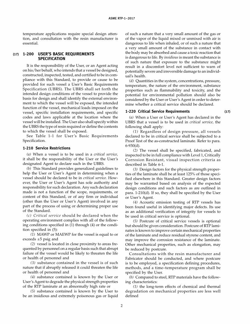
(17) INTRODUCTION
GENERAL
The use of reinforced thermoset plastic (RTP) vessels,with maximum allowable working pressure (MAWP)and maximum allowable external working pressure(MAEWP) not exceeding 15 psig external and/or 15 psiginternal above any hydrostatic head, that contain corro-sive and otherwise hazardous materials, dictates theneed for rules and/or stress analysis concerning materi-als of construction, design, fabrication, quality control,and inspection of such equipment. In developing rulesfor RTP, the Committee has adapted the principles ofrules included in Section VIII, Division 1 of the ASMEBoiler and Pressure Vessel Code, wherever they areapplicable.
Adaption of standard rules to RTP requires recogni-tion of differences that exist between metallic materialsand RTP. These differences are addressed in the remain-der of this Introduction.
MATERIALS AND ASSEMBLY
In the absence of ASTM standards, RTP laminate spec-ifications (Part 2) have been developed for use with thisASME Standard. These specifications include laminatecomposition and properties. Laminates (composites)manufactured by contact molding and by filament wind-ing are covered.
These materials of construction are not available incommerce as mill shapes such as sheet and plate forforming and joining by the Fabricator. They are pro-duced in situ on a mandrel or mold by the Fabricatorduring fabrication of RTP equipment components. EachFabricator, as part of his or her shop qualification tothis Standard, must demonstrate capability to producelaminates meeting the requirements of the laminatespecifications.
Assembly of components such as shells, heads, andnozzles requires joining by secondary bonding. This
xiv
operation involves fit-up, surface preparation, and over-wrapping with a laminate of composition equivalent tothe laminates being joined. Secondary Bonders mustbe qualified individually by the procedures detailed inMandatory Appendix M-5.
DESIGN
Design by formulas and by stress analysis are bothincluded in this Standard. Consideration is given bothto ultimate strength and to limiting strain. Time andtemperature dependence of RTP laminate properties arerecognized.
The ultimate stress consideration is required to ensuresafety against catastrophic failure over a reasonably longterm. The design factors of Subparts 3A and 3B includeconsideration of variability of quality in the labor-intensive fabricating operation. The strain considera-tions are required to ensure long-term operation undercyclic stress (fatigue) without cracking the resin matrixof the composite laminate, thus maintaining maximumcorrosion resistance. More than 20 years of successfulexperience, together with test data, have shown theseconsiderations to be valid.
INSPECTION
Reliance is placed on careful auditing of theFabricator’s Quality Control Program and close visualinspection of equipment during fabrication and of fin-ished equipment.
NONMANDATORY APPENDICES
Nonmandatory Appendices are provided in thisStandard for reference only. The content ofNonmandatory Appendices is not a requirement evenwhen referenced in mandatory parts of this Standard.
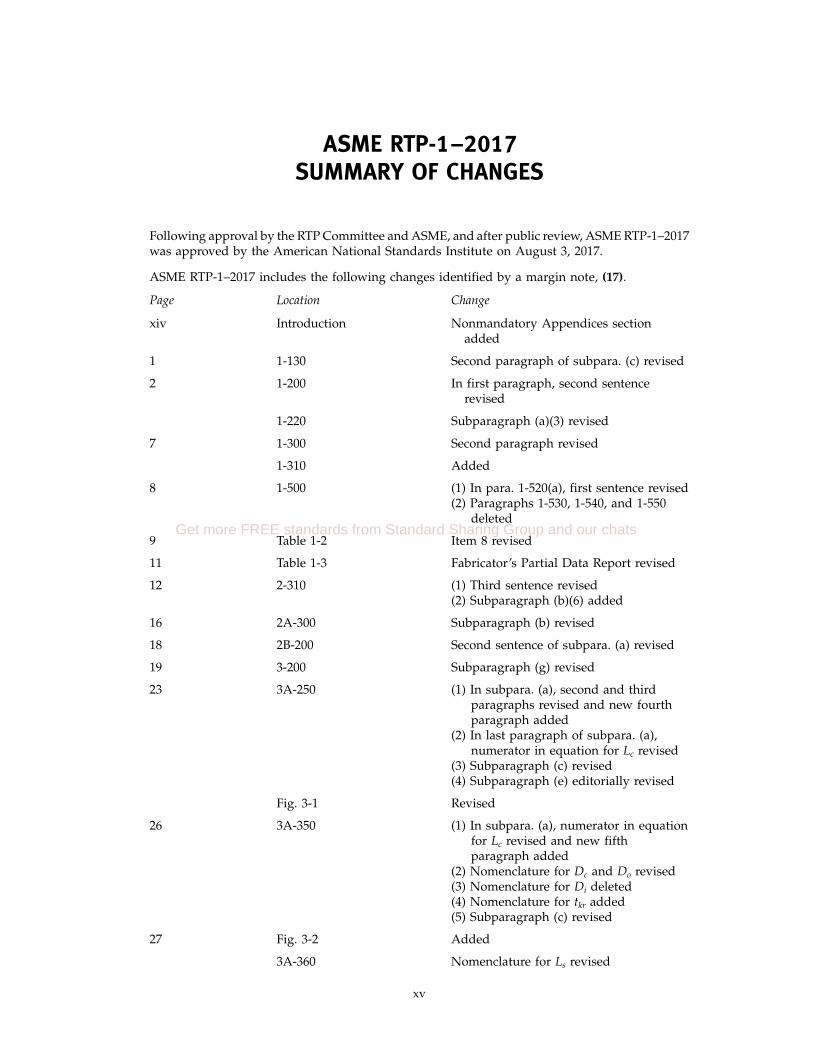
ASME RTP-1–2017SUMMARY OF CHANGES
Following approval by the RTP Committee and ASME, and after public review, ASME RTP-1–2017was approved by the American National Standards Institute on August 3, 2017.
ASME RTP-1–2017 includes the following changes identified by a margin note, (17).
Page Location Change
xiv Introduction Nonmandatory Appendices sectionadded
1 1-130 Second paragraph of subpara. (c) revised
2 1-200 In first paragraph, second sentencerevised
1-220 Subparagraph (a)(3) revised
7 1-300 Second paragraph revised
1-310 Added
8 1-500 (1) In para. 1-520(a), first sentence revised(2) Paragraphs 1-530, 1-540, and 1-550
deleted
9 Table 1-2 Item 8 revised
11 Table 1-3 Fabricator’s Partial Data Report revised
12 2-310 (1) Third sentence revised(2) Subparagraph (b)(6) added
16 2A-300 Subparagraph (b) revised
18 2B-200 Second sentence of subpara. (a) revised
19 3-200 Subparagraph (g) revised
23 3A-250 (1) In subpara. (a), second and thirdparagraphs revised and new fourthparagraph added
(2) In last paragraph of subpara. (a),numerator in equation for Lc revised
(3) Subparagraph (c) revised(4) Subparagraph (e) editorially revised
Fig. 3-1 Revised
26 3A-350 (1) In subpara. (a), numerator in equationfor Lc revised and new fifthparagraph added
(2) Nomenclature for Dc and Do revised(3) Nomenclature for Di deleted(4) Nomenclature for tkr added(5) Subparagraph (c) revised
27 Fig. 3-2 Added
3A-360 Nomenclature for Ls revised
xv
Get more FREE standards from Standard Sharing Group and our chats

Page Location Change
34 4-330 Subparagraphs (c) and (d) revised
39 Fig. 4-3 Third sentence of General Note deleted
57 6-930 First paragraph of subpara. (d) revised
58–63 6-950 Last paragraph of subpara. (c) revised
Table 6-1 On last page, Notes column for finalentry revised
64, 65 7-600 Subparagraphs (b)(2) and (d) revised
70–72 Part 8 (1) Revised in its entirety(2) Figure 1-1 relocated from Part 1 and
redesignated as Figure 8-1
112, 113 Mandatory Appendix M-4 Editorially revised; “must” revised to“shall” throughout
122 Table M6-1 Item 2 revised
129 M7-300 Last paragraph revised
134 Table M8-1 Title revised
140–142 Mandatory Appendix M-10 Updated
145 M12A-100 Subparagraphs (a), (c), and (e) revised
M12B-100 Revised
M12B-200 In first paragraph, sixth sentence revised
146–148 Table M12B-1 Revised in its entirety
M12B-400 Subparagraphs (a) and (b) revised
M12B-500 Revised in its entirety
M12B-600 Revised in its entirety
Table M12B-2 Revised in its entirety
M12B-611 Revised
M12B-612 Subparagraphs (a) and (c) revised
M12B-613 (1) Former M12B-613.1 deleted andformer M12B-613.2 throughM12B-613.5 redesignated asM12B-613.1 through M12B-613.4,respectively
(2) M12B-613.3 revised in its entirety(3) M12B-613.4 revised
M12B-614.1 Revised
M12B-614.2 Revised in its entirety
150 M12B-614.3 Revised in its entirety
M12B-614.4 First sentence of subpara. (a) revised
xvi

Page Location Change
151–154 M12B-632 Subparagraph (a) revised
M12B-634.1 Last sentence of subpara. (a) deleted
Table M12B-6 (1) Reference to “Shelf life” deleted(2) Column 5 for Shelf Life Expiration
Date deleted, and remaining columnsrenumbered
M12B-634.2 Revised
156 M12B-652 Subparagraphs (a) and (b) revised
M12B-654.1 Revised
M12B-654.2 Subparagraphs (a) and (b) revised
M12B-654.3 Revised in its entirety
M12B-654.4 Revised
172 M12G-510 Subparagraph (d) revised
M12G-520 Last sentence deleted
179, 180 M12H-300 Revised in its entirety
M12H-311 Revised in its entirety
M12H-312 Revised
M12H-313 Editorially revised; “will” replaced with“shall” throughout
M12H-400 Revised in its entirety
Table M12H-1 (1) Deleted(2) Former Table M12H-2 redesignated as
new Table M12H-1 and revised
M12H-500 Revised
M12H-600 Added
250 Nonmandatory Editorially revisedAppendix NM-6
273, 274 NM9-300 Subparagraphs (b), (g), (h), (i)(1), and(i)(5) revised
275 Fig. NM9-3 General Note (a) revised
307 Nonmandatory DeletedAppendix NM-14
SPECIAL NOTE:
The interpretations to ASME RTP-1 are no longer included in the edition. Interpretations can beaccessed on the ASME Web site under the Committee Pages at http://cstools.asme.org/.
xvii
Get more FREE standards from Standard Sharing Group and our chats

INTENTIONALLY LEFT BLANK
xviii

ASME RTP-1–2017
REINFORCED THERMOSET PLASTICCORROSION-RESISTANT EQUIPMENT
Part 1General Requirements
1-100 INTRODUCTION
Part 1 of this Standard defines the requirements thatare applicable to all reinforced thermoset plastic corro-sion resistant vessels fabricated to this Standard andshall be used in conjunction with the specific require-ments in other Parts and Mandatory Appendices of thisStandard.
1-110 Scope
(a) This Standard applies to stationary vessels usedfor the storage, accumulation, or processing of corrosiveor other substances at pressures not exceeding 15 psigexternal and/or 15 psig internal above any hydro-static head.
(b) In relation to the geometry of vessels, the scopeof this Standard shall include the following:
(1) where external piping is to be connected to thevessel
(-a) the first threaded joint for screwedconnections
(-b) the face of the first flange for boltedconnections
(-c) the vessel side sealing surface for proprietaryconnections or fittings
(2) the vessel attachment joint when an attachmentis made to either the external or internal surface of thevessel
(3) covers for vessel openings, such as manhole andhandhole covers
(4) the vessel side sealing surface for proprietaryfittings, such as gages and instruments, for which rulesare not provided by this Standard
1-120 Exclusions
The following types of reinforced thermoset plasticequipment are excluded from the rules of this Standard:
(a) vessels with MAWP or MAEWP in excess of15 psig
(b) hoods, ducts, and stacks(c) fans and blowers
1
(d) vessel internals such as entrainment separators,chevron blades, packing support plates, and liquid dis-tribution plates
(e) pumps(f) pipe or piping (see ASME B31.3)(g) fully buried underground closed vessels
1-130 Application Limitations
Vessels specified, designed, fabricated, and certifiedby the Fabricator as conforming to this Standard shallbe limited to the following pressure and temperaturelimits:
(a) Maximum Internal Pressure1
(1) With Proof Test of As-Constructed Laminate. TheMAWP, measured at the top of the vessel, shall not begreater than 15 psig.
(2) Without Proof Test of As-Constructed Laminate.The MAWP shall not be greater than 2 psig.
(b) Maximum External Pressure1
(1) With Proof Test of As-Constructed Laminate. TheMAEWP shall not be greater than 15 psig.
(2) Without Proof Test of As-Constructed Laminate.The MAEWP shall not be greater than 2 psig.
(c) Temperature Limits. The design temperature shallbe limited to a value for which mechanical propertieshave been determined by the procedures inparas. 2A-300(b) and 2B-200(a), and the chemical resist-ance has been established by the material selection pro-cess identified in Table 1-1, item 3.
Operating temperatures to 180°F maximum are com-monly encountered and a large body of mechanicalproperty and chemical resistance data exists to facilitatedesign. The design temperature shall not be less thanthe maximum operating temperature. See para. 3-300.Applications above 180°F require that the designer rec-ognizes and accounts for possible reduced mechanicalproperties at the elevated temperature and possiblydecreasing mechanical properties with time as a conse-quence of thermal and chemical exposure. Such elevated
1 Refer to para. 6-930(d) for Proof Test requirements.
(17)
Get more FREE standards from Standard Sharing Group and our chats
(17)
ASME RTP-1–2017
temperature applications require special design atten-tion, and consultation with the resin manufacturer isessential.
1-200 USER’S BASIC REQUIREMENTSSPECIFICATION
It is the responsibility of the User, or an Agent actingon his/her behalf, who intends that a vessel be designed,constructed, inspected, tested, and certified to be in com-pliance with this Standard, to provide or cause to beprovided for such vessel a User’s Basic RequirementsSpecification (UBRS). The UBRS shall set forth theintended design conditions of the vessel to provide thebasis for design and shall identify the external environ-ment to which the vessel will be exposed, the intendedfunction of the vessel, mechanical loads imposed on thevessel, specific installation requirements, and specificcodes and laws applicable at the location where thevessel will be installed. The User also shall specify withinthe UBRS the type of resin required or define the contentsto which the vessel shall be exposed.
See Table 1-1 for User ’s Basic RequirementsSpecification.
1-210 Service Restrictions
(a) When a vessel is to be used in a critical service,it shall be the responsibility of the User or the User’sdesignated Agent to declare such in the UBRS.
(b) This Standard provides generalized guidelines tohelp the User or User’s Agent in determining when avessel should be declared to be in critical service. How-ever, the User or User’s Agent has sole authority andresponsibility for such declaration. Any such declarationmade is not a function of the scope, requirements, orcontent of this Standard, or of any firm or individual(other than the User or User’s Agent) involved in anypart of the process of using or determining proper useof the Standard.
(c) Critical service should be declared when theoperating environment complies with all of the follow-ing conditions specified in (1) through (4) or the condi-tion specified in (5):
(1) MAWP or MAEWP for the vessel is equal to orexceeds ±5 psig and
(2) vessel is located in close proximity to areas fre-quented by personnel on a regular basis such that abruptfailure of the vessel would be likely to threaten the lifeor health of personnel and
(3) substance contained in the vessel is of suchnature that if abruptly released it could threaten the lifeor health of personnel and
(4) substance contained is known by the User orUser’s Agent to degrade the physical strength propertiesof the RTP laminate at an abnormally high rate or
(5) substance contained is known by the User tobe an insidious and extremely poisonous gas or liquid
2
of such a nature that a very small amount of the gas orof the vapor of the liquid mixed or unmixed with air isdangerous to life when inhaled, or of such a nature thata very small amount of the substance in contact withthe body may be absorbed and cause a toxic reaction thatis dangerous to life. By insidious is meant the substance isof such nature that exposure to the substance mightresult in a discomfort level not sufficient to warn ofpotentially severe and irreversible damage to an individ-ual’s health.
(d) Quantities in the system, concentrations, pressure,temperature, the nature of the environment, substanceproperties such as flammability and toxicity, and thepotential for environmental pollution should also beconsidered by the User or User’s Agent in order to deter-mine whether a critical service should be declared.
1-220 Critical Service Requirements(a) When a User or User’s Agent has declared in the
UBRS that a vessel is to be used in critical service, thefollowing shall apply:
(1) Regardless of design pressure, all vesselsdeclared to be in critical service shall be subjected to aProof Test of the as-constructed laminate. Refer to para.6-930(d).
(2) The vessel shall be specified, fabricated, andinspected to be in full compliance with Level 1, CriticallyCorrosion Resistant, visual inspection criteria asdescribed in Table 6-1.
(3) Design factors for the physical strength proper-ties of the laminate shall be at least 125% of those speci-fied elsewhere in this Standard. Greater design factorsmay be warranted based on analysis of the expecteddesign conditions and such factors as are outlined inpara. 1-210(d). If so, they shall be specified by the Useror User’s Agent.
(4) Acoustic emission testing of RTP vessels hasbeen found useful in identifying major defects. Its useas an additional verification of integrity for vessels tobe used in critical service is optional.
(5) Postcure of critical service vessels is optionalbut should be given consideration. Postcure of RTP lami-nates is known to improve certain mechanical propertiesof the laminate and reduce residual styrene content, andmay improve the corrosion resistance of the laminate.Other mechanical properties, such as elongation, maybe reduced by postcure.
Consultations with the resin manufacturer andFabricator should be conducted, and where postcureis to be employed, a specification defining procedures,methods, and a time–temperature program shall bespecified by the User.
(b) Compared to steel, RTP materials have the follow-ing characteristics:
(1) the long-term effects of chemical and thermaldegradation on mechanical properties are less welldefined
(17)

ASME RTP-1–2017
Table 1-1 User’s Basic Requirements Specification (UBRS)(As Required by the Provisions of ASME RTP-1)
Page 1 of 4
RTP Edition No.
UBRS Revision No.
User firm name
User’s Agent firm name
Title of equipment
User’s designation no.
Installation location (name and address)
UBRS prepared by (User or User’s Agent):
Name Phone no. Date
Address
1. Equipment description (equipment sketch and nozzle schedule must be attached):
2. Additional Fabricator responsibilities:
[ ] Special requirements
[ ] Acoustic emission testing
[ ] Inspection or testing requirements not listed in the Standard
[ ]
[ ]
[ ] User waives visual inspection prior to application of final exterior coat: [ ] Yes [ ] No
[ ] Visual inspection acceptance level (refer to Table 6-1 of ASME RTP-1): [ ] Level 1 [ ] Level 2
Quantity limitations for gaseous air bubbles or blisters
3
Get more FREE standards from Standard Sharing Group and our chats

ASME RTP-1–2017
Table 1-1 User’s Basic Requirements Specification (UBRS) (Cont’d)(As Required by the Provisions of ASME RTP-1)
Page 2 of 4
RTP Edition No.
UBRS Revision No.
[ ] Additional inspection aids/methods [refer to para. 6-940(c) of ASME RTP-1]
3. Material selection
3.1 Material selection by:
[ ] Resin manufacturer (include data per section 4 of this document)
[ ] Fabricator (include data per section 4 of this document)
[ ] End User. Applicable User’s specifications/standards, codes, ordinances, FDA requirements, etc. (list and specify;
attach copies of local code/ordinance requirements)
[ ] Other
3.2 Material of construction:
Resin Catalyst/cure system
Veil Barcol hardness per para. 6-910(b)(4)
[ ] Lift lugs: [ ] RTP [ ] Carbon steel [ ] Other
[ ] Hold-down lugs: [ ] RTP [ ] Carbon steel [ ] Other
4. Chemical service data (shall be provided when Fabricator or resin manufacturer is making material selection)
4.1 Description of process function and process sequence:
4.2 Contents:
Concentration
Chemical Name Max. % Min. % Exposure Time
4.3 pH range: max. min.
5. Design
5.1 Design conditions:
Operating (for reference only) Design
Internal pressure
External pressure
Temperature
Specific gravity
Normal (used for seismic design only) Maximum
Liquid level
4
ASME RTP-1–2017
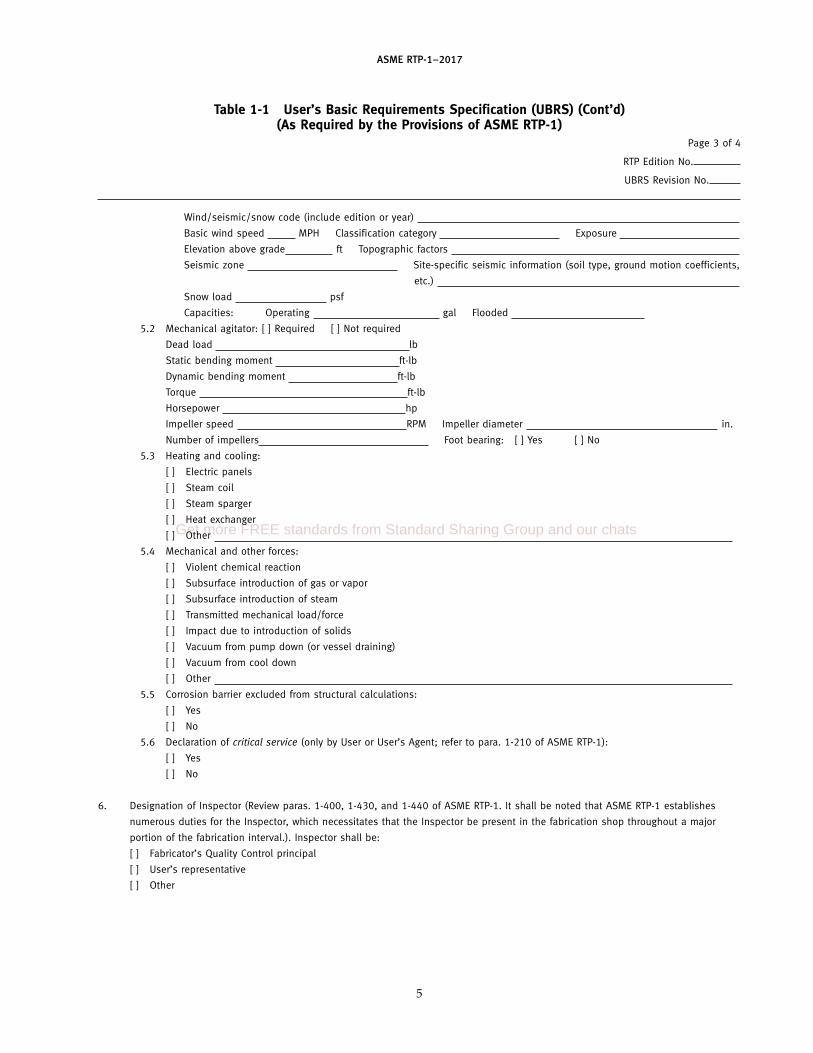
Table 1-1 User’s Basic Requirements Specification (UBRS) (Cont’d)(As Required by the Provisions of ASME RTP-1)
Page 3 of 4
RTP Edition No.
UBRS Revision No.
Wind/seismic/snow code (include edition or year)
Basic wind speed MPH Classification category Exposure
Elevation above grade ft Topographic factors
Seismic zone Site-specific seismic information (soil type, ground motion coefficients,
etc.)
Snow load psf
Capacities: Operating gal Flooded
5.2 Mechanical agitator: [ ] Required [ ] Not required
Dead load lb
Static bending moment ft-lb
Dynamic bending moment ft-lb
Torque ft-lb
Horsepower hp
Impeller speed RPM Impeller diameter in.
Number of impellers Foot bearing: [ ] Yes [ ] No
5.3 Heating and cooling:
[ ] Electric panels
[ ] Steam coil
[ ] Steam sparger
[ ] Heat exchanger
[ ] Other
5.4 Mechanical and other forces:
[ ] Violent chemical reaction
[ ] Subsurface introduction of gas or vapor
[ ] Subsurface introduction of steam
[ ] Transmitted mechanical load/force
[ ] Impact due to introduction of solids
[ ] Vacuum from pump down (or vessel draining)
[ ] Vacuum from cool down
[ ] Other
5.5 Corrosion barrier excluded from structural calculations:
[ ] Yes
[ ] No
5.6 Declaration of critical service (only by User or User’s Agent; refer to para. 1-210 of ASME RTP-1):
[ ] Yes
[ ] No
6. Designation of Inspector (Review paras. 1-400, 1-430, and 1-440 of ASME RTP-1. It shall be noted that ASME RTP-1 establishes
numerous duties for the Inspector, which necessitates that the Inspector be present in the fabrication shop throughout a major
portion of the fabrication interval.). Inspector shall be:
[ ] Fabricator’s Quality Control principal
[ ] User’s representative
[ ] Other
5
Get more FREE standards from Standard Sharing Group and our chats

ASME RTP-1–2017
Table 1-1 User’s Basic Requirements Specification (UBRS) (Cont’d)(As Required by the Provisions of ASME RTP-1)
Page 4 of 4
RTP Edition No.
UBRS Revision No.
Inspector’s name Telephone
Company
Address
7. Approval of UBRS
7.1 Authorized User’s representative:
Name Title
Signature Date
7.2 Authorized Fabricator’s representative:
Name Title
Signature Date
Additional requirements:
GENERAL NOTE: This form may be reproduced and used without written permission from ASME if used for purposes other than republication.
6
(17)
(17)
ASME RTP-1–2017
(2) flammability(3) limited impact resistance(4) low ductility that could lead to abrupt rupture
due to excess loading(5) the long-term effects of creep are less well
defined(c) On the basis of (b) above, the following additional
safeguards should be carefully considered:(1) location of vessels(2) guarding against physical damage and abuse(3) fire protection(4) prevention of excess loading imposed by attach-
ments or auxiliary equipment(5) periodic structural and material inspections
and tests
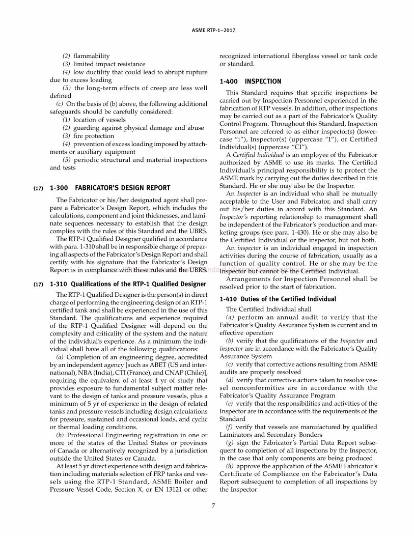
1-300 FABRICATOR’S DESIGN REPORT
The Fabricator or his/her designated agent shall pre-pare a Fabricator’s Design Report, which includes thecalculations, component and joint thicknesses, and lami-nate sequences necessary to establish that the designcomplies with the rules of this Standard and the UBRS.
The RTP-1 Qualified Designer qualified in accordancewith para. 1-310 shall be in responsible charge of prepar-ing all aspects of the Fabricator’s Design Report and shallcertify with his signature that the Fabricator’s DesignReport is in compliance with these rules and the UBRS.
1-310 Qualifications of the RTP-1 Qualified Designer
The RTP-1 Qualified Designer is the person(s) in directcharge of performing the engineering design of an RTP-1certified tank and shall be experienced in the use of thisStandard. The qualifications and experience requiredof the RTP-1 Qualified Designer will depend on thecomplexity and criticality of the system and the natureof the individual’s experience. As a minimum the indi-vidual shall have all of the following qualifications:
(a) Completion of an engineering degree, accreditedby an independent agency [such as ABET (US and inter-national), NBA (India), CTI (France), and CNAP (Chile)],requiring the equivalent of at least 4 yr of study thatprovides exposure to fundamental subject matter rele-vant to the design of tanks and pressure vessels, plus aminimum of 5 yr of experience in the design of relatedtanks and pressure vessels including design calculationsfor pressure, sustained and occasional loads, and cyclicor thermal loading conditions.
(b) Professional Engineering registration in one ormore of the states of the United States or provincesof Canada or alternatively recognized by a jurisdictionoutside the United States or Canada.
At least 5 yr direct experience with design and fabrica-tion including materials selection of FRP tanks and ves-sels using the RTP-1 Standard, ASME Boiler andPressure Vessel Code, Section X, or EN 13121 or other
7
recognized international fiberglass vessel or tank codeor standard.
1-400 INSPECTION
This Standard requires that specific inspections becarried out by Inspection Personnel experienced in thefabrication of RTP vessels. In addition, other inspectionsmay be carried out as a part of the Fabricator’s QualityControl Program. Throughout this Standard, InspectionPersonnel are referred to as either inspector(s) (lower-case “i”), Inspector(s) (uppercase “I”), or CertifiedIndividual(s) (uppercase “CI”).
A Certified Individual is an employee of the Fabricatorauthorized by ASME to use its marks. The CertifiedIndividual’s principal responsibility is to protect theASME mark by carrying out the duties described in thisStandard. He or she may also be the Inspector.
An Inspector is an individual who shall be mutuallyacceptable to the User and Fabricator, and shall carryout his/her duties in accord with this Standard. AnInspector’s reporting relationship to management shallbe independent of the Fabricator’s production and mar-keting groups (see para. 1-430). He or she may also bethe Certified Individual or the inspector, but not both.
An inspector is an individual engaged in inspectionactivities during the course of fabrication, usually as afunction of quality control. He or she may be theInspector but cannot be the Certified Individual.
Arrangements for Inspection Personnel shall beresolved prior to the start of fabrication.
1-410 Duties of the Certified Individual
The Certified Individual shall(a) perform an annual audit to verify that the
Fabricator’s Quality Assurance System is current and ineffective operation
(b) verify that the qualifications of the Inspector andinspector are in accordance with the Fabricator’s QualityAssurance System
(c) verify that corrective actions resulting from ASMEaudits are properly resolved
(d) verify that corrective actions taken to resolve ves-sel nonconformities are in accordance with theFabricator’s Quality Assurance Program
(e) verify that the responsibilities and activities of theInspector are in accordance with the requirements of theStandard
(f) verify that vessels are manufactured by qualifiedLaminators and Secondary Bonders
(g) sign the Fabricator’s Partial Data Report subse-quent to completion of all inspections by the Inspector,in the case that only components are being produced
(h) approve the application of the ASME Fabricator’sCertificate of Compliance on the Fabricator ’s DataReport subsequent to completion of all inspections bythe Inspector
Get more FREE standards from Standard Sharing Group and our chats

(17)
ASME RTP-1–2017
1-420 Qualifications of the Certified IndividualThe Certified Individual shall meet the following
qualifications:(a) education and experience (minimum of high
school diploma and 5 yr of experience in the RTP corro-sion resistance industry)
(b) demonstrated inspection ability to the Fabricatoremploying him/her
(c) satisfactory expertise and experience according tothe complexity of the assignment
(d) knowledge of ASME RTP-1(e) knowledge of Fabricator ’s Quality Assurance
Program and shop procedure(f) knowledge and ability to evaluate and monitor
procedures and performance(g) knowledge of keeping and maintaining records
1-430 Inspector’s DutyThe Inspector shall make all the inspections necessary
to verify that the requirements of this Standard and theFabricator’s Design Report have been met. The Inspectorof the vessel does not have the duty of determining thecompleteness or correctness of the design calculations;however, he/she does have the duty of establishing thatthe Fabricator of the vessel has the UBRS and theFabricator’s Design Report on file, and that the require-ments of para. 1-300 have been met.
1-440 Access for the InspectorThe Inspector shall be permitted free access, at all
times while work on the vessel is being performed, toall parts of the Fabricator’s shop that concern the fabrica-tion of the vessel and to the site of field fabrication orerection during the period of field fabrication, erection,and testing. The Fabricator shall keep the Inspectorinformed of the progress of the work and shall notifyhim/her in advance when the vessel or materials willbe ready for any required tests or inspection.
1-500 FABRICATOR’S QUALITY CONTROLPROGRAM
A written description of the Quality Control Program,that explains which documents and procedures the
8
Fabricator will use to produce equipment to thisStandard, shall be available for review. The QualityControl Program shall be in accordance with the require-ments of Mandatory Appendix M-4. See NonmandatoryAppendix NM-6 for an example of a Fabricator’s QualityControl Program.
1-510 Fabricator’s Demonstration of Capability
See Part 7.
1-520 Certification
(a) In order for any vessel to be marked with theASME Certification Mark with RTP Designator, theFabricator shall meet the requirements of ASME CA-1(refer to Part 8). The Fabricator has the responsibility ofcomplying with all the requirements of this Standardand the UBRS. The Fabricator also has the responsibilityto certify that any work done by others also complieswith all the requirements of this Standard. This responsi-bility includes providing the Inspector with all requiredinformation and assuring that the detailed examinationsand tests are performed at the stages of fabrication thatpermit them to be meaningful.
(b) The Certified Individual, subsequent to comple-tion of all inspections by the Inspector (see Part 6), shallcomplete and sign the Fabricator ’s Data Report orFabricator ’s Partial Data Report as applicable. SeeTables 1-2 and 1-3. An original document of such DataReports shall be sent or delivered to the User (or User’sAgent). Copies of such Data Reports shall be retainedin the Fabricator’s record system in accordance withMandatory Appendix M-4, para. M4-300(c).
(c) The Inspector shall sign the Inspector ’sCertification on the Fabricator’s Data Report (or PartialData Report) only when he/she is satisfied that allrequirements of this Standard have been met.
(d) Vessels may also be registered by filing theFabricator’s Data Report with the National Board ofBoiler and Pressure Vessel Inspectors, 1055 CrupperAvenue, Columbus, OH 43229.

ASME RTP-1–2017
(17)
(Nat'l Bd. no.)
(AE or other)
(1) (specify units)
(2) (specify units)
14. Supports: (describe: if legs how many and size, if skirt describe, if support ring mat'l. and type, if saddles mat'l. and type)
15. Material selection: Resin (specific nomenclature & cure system):
Resin manufacturer Fabricator
13. Vessel fabricated for storage of: (briefly describe chemicals to be contained or stored)
Declaration of critical service: ( yes or no )
11. Safety relief or atmospheric vent size and location:(identify location, item designation, type, and size)
12. Inspection openings:(describe size, quantity, and general location)
(top, bottom, ends) (structural only) (min. and max. measured) (ASME F&D, 2:1 elliptical, flat)
10. Heads: Type: (type I, type II, type X) (specify veil, sequence, or type of thermoplastic and thk.)
Location Nominal Thickness Barcol Hardness Shape
(type I, type II, type X) (structural only) (specify veil, sequence, or type of thermoplastic and thk.)
(specify units) (specify units) (min. and max. measured)
Maximum allowable working pressure (specify units):
Maximum allowable external working pressure (specify units):
NDE:
Dia.:
Quantity limitations for gaseous air bubbles or blisters:
(Table 6-1, Level 1 or 2)
9. Shell: Type:
7. Laminate proof tests performed per para. 1-130:(yes/no) (yes/no)
8. Fabricated for the following: Contents specific gravity:
5. Vessel fabricated in accordance with UBRS rev.: (rev. and date)
6. Vessel designed according to Part 3A or 3B:(indicate A or B or combination)
4. Type:(horiz. or vert. vessel) (mfr’s. serial) (dwg. no.)
2. Fabricated for: (name and address of Purchaser)
3. Location of installation:(name and address)
Table 1-2 Fabricator’s Data Report
(As Required by the Provisions of ASME RTP-1)
1. Fabricated and certified by: (name and address of Fabricator)
End User
Other (explain)
16. Fluid concentrations and temperatures as listed in the UBRS:
Vessel no.: Year built:
Remarks:
ASME RTP-1 edition:
Data pkg. and Design Report complete:
If yes, results reviewed and accepted: .
at maximum temp. (specify units):
at maximum temp. (specify units):
Struct. visual acceptance level: (Table 6-1, Level 1 or 2)
Liner visual acceptance level:
Liner:
Barcol hardness:
Nom. thk.:
Length:
Liner:
9
Get more FREE standards from Standard Sharing Group and our chats

ASME RTP-1–2017
F ABRIC AT OR ’S CERTIFIC AT E O F COMPLIANCE
We certify the information in this Data Report to be correct and that the vessel has been designed and fabricated in accordance with all requirements of ASME RTP-1 and the User’s Basic Requirements Specification .
ASME RTP-1– No.(Certificate of Authorization and expiration date)
Date (mont h / da y / year) (Fabricator’s name) (signature of Certified Individual)
(prin t o r typ e n ame)
(address of fabrication site)
INSPECTO R’ S C ERTIFICA TIO N
I, the undersigned, employed by of , (print company name) (city and state)
have inspected the vessel described in this Fabricator’s Data Report and believe that the Fabricator has constructed it in accordance with the requirements of ASME RTP-1. By signing this certificate, neither the Inspector nor his/her employer (if other than the Fabricator) makes an y w arranty, expressed or implied, concerning performance of the vessel.
Date (mont h / da y / year) (Inspector’s signature)
(prin t o r type name)
GENERAL NOTES : (a) The following documents, all updated to as-built status, are required attachments to this Data Report:
(1) User’s Basic Requirements Specification (UBRS) (2) Desig n R eport signed and stamped by the Professional Engineer (3) drawings (4) copies of all quality control forms used in the Fabricator’s Quality Control Program during the course of
fabrication .
(b) This form ma y b e reproduced and used withou t w ritten permission fro m A SM E i f used for purposes other than republication.
Table 1-2 Fabricator’s Data Report (Cont’d)
(As Required by the Provisions of ASME RTP-1)
17. Nozzles/fittings:
Purpose/Use
The above documents shall be part of the Fabricator’s and End User’s records. As an option, the data report may be submitted (without above documentation) to the National Board for vessel registration.
Quantity Size
10
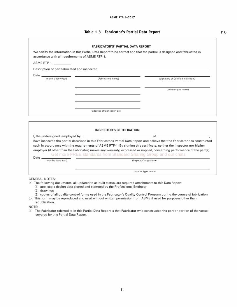
ASME RTP-1–2017
(17)Table 1-3 Fabricator’s Partial Data Report
GENERAL NOTES:(a) The following documents, all updated to as-built status, are required attachments to this Data Report: (1) applicable design data signed and stamped by the Professional Engineer (2) drawings (3) copies of all quality control forms used in the Fabricator’s Quality Control Program during the course of fabrication(b) This form may be reproduced and used without written permission from ASME if used for purposes other than republication.
NOTE:(1) The Fabricator referred to in this Partial Data Report is that Fabricator who constructed the part or portion of the vessel covered by this Partial Data Report.
(print or type name)
FABRICATOR’S1 PARTIAL DATA REPORT
We certify the information in this Partial Data Report to be correct and that the part(s) is designed and fabricated in
accordance with all requirements of ASME RTP-1.
ASME RTP-1–
Description of part fabricated and inspected
Date(month / day / year) (Fabricator’s name) (signature of Certified Individual)
(address of fabrication site)
INSPECTOR’S CERTIFICATION
I, the undersigned, employed by of ,
have inspected the part(s) described in this Fabricator’s Partial Data Report and believe that the Fabricator has constructed
such in accordance with the requirements of ASME RTP-1. By signing this certificate, neither the Inspector nor his/her
employer (if other than the Fabricator) makes any warranty, expressed or implied, concerning performance of the part(s).
(month / day / year) (Inspector’s signature)
(print or type name)
Date
11
Get more FREE standards from Standard Sharing Group and our chats

(17)
ASME RTP-1–2017
Part 2Materials
2-100 SCOPE
Part 2 defines the materials comprising the glass fiberreinforced thermoset polyester and vinyl ester resin lam-inates, and the types of laminates used to fabricate theRTP corrosion-resistant equipment. See MandatoryAppendix M-12 for thermoplastic lining materials usedin dual laminate vessels.
2-200 LAMINATE COMPOSITIONS
The composition of the allowable RTP laminates islimited to the specific materials in Part 2 and MandatoryAppendices M-1 and M-2. Subpart 2A covers predefinedstandard laminates as representative flat laminates.Subpart 2B covers laminates developed using theLamination Analysis Method, by which the modulusproperties of laminates are obtained. Subpart 2C coverspermissible tolerances for laminate thickness variation.
Construction and testing for properties of design basislaminates are required in Subpart 2A. Calculation oflaminate properties by the Lamination Analysis Method(Mandatory Appendix M-3) is addressed in Subpart 2B.
Minimum inspections and tests to be performed onreinforcements, prior to their use, are described inMandatory Appendix M-1.
Minimum inspections and tests to be performed onresins, curing agents, and common additives, prior totheir use, are described in Mandatory Appendix M-2.
2-210 Resin and Reinforcement Substitution
The Fabricator shall use the same resins and reinforce-ments during fabrication as used in the design basislaminates and Lamination Analysis Method, with theexception of the surfacing veil, which may be changedas required for corrosion resistance.
2-300 MATERIALS
2-310 Resin Matrix
The resin shall be that polyester or vinyl ester specifiedby the User’s Basic Requirements Specification. Onlyresins with a heat deflection temperature (HDT) of atleast 180°F (82°C) per ASTM D648 with a 264 psi loadingand a 1⁄8-in. specimen, as published by the resin manufac-turer, shall be used. Properties established through test-ing at ambient temperature are valid up to 180°F (82°C)or up to 35°F (19°C) below the resin’s HDT, whichever
12
is lower. When a maximum flame retardancy is specifiedby the UBRS, the flame spread rating shall be deter-mined by the resin manufacturer according to ASTM E84using all mat laminates greater than 0.1 in. thick. Verifi-cation of the flame spread rating is not required as apart of laminate qualification. Since flame spread canbe determined only on flat laminate panels, verificationis not required on fabricated equipment. Prior to use inlaminate fabrications, the resin shall be inspected, tested,and found acceptable by the inspections and tests speci-fied in Mandatory Appendix M-2.
(a) The catalyst/promoter/accelerator system shallbe as recommended by the resin manufacturer and speci-fied in the Fabricator’s written procedures.
(b) The resin shall not contain any pigment, dyes,colorants, or filler, except as follows:
(1) A thixotropic agent that does not interfere withvisual inspection of laminate quality, or with therequired corrosion resistance of the laminate, may beadded for viscosity control.
NOTE: The addition of a thixotropic agent may reduce the resist-ance of a laminate to some corrosive chemical environments. It isthe responsibility of the Fabricator to obtain approval from theselector of the resin prior to using a thixotropic agent in the innersurface (para. 2A-221) or the interior layer (para. 2A-222).
(2) Resin pastes used to fill crevices before overlayshall not be subject to these limitations.
(3) Pigments, dyes, or colorants may be added tothe exterior surface when specified by the UBRS.
NOTE: The addition of pigment, dyes, or colorants may interferewith visual inspection of laminate quality.
(4) Flame retardant synergists shall be used onlywhen required in the UBRS. If fire retardant synergistswere used to obtain the specified ASTM E84 flamespread rating, the same type and amount must be usedin the laminate.
NOTE: The addition of fire retardant synergists may interferewith visual inspection of laminate quality.
(5) Common additives, as described in MandatoryAppendix M-2, Article G, may be added without requali-fying the standard laminate.
(6) Fillers or additives for abrasion resistance, ther-mal shock resistance, and electrical conductivity areallowed. A requalification of the design basis laminateis required if these fillers or additives are added to thestructural laminate. All fillers or additives shall be

ASME RTP-1–2017
approved by the End User and the resin supplier forthe design chemical service.
Note that fillers may interfere with visual inspection ofthe laminate and could affect properties of the laminate.
2-320 Fiber Reinforcement
Fiber reinforcements shall be in compliance with thefollowing references for each material type:
(a) fiberglass surfacing veil, organic fiber surfacingveil, carbon fiber surfacing veil, and fiberglass choppedstrand mat — Mandatory Appendix M-1, Article A
(b) fiberglass spray-up roving and filament windingroving — Mandatory Appendix M-1, Article B
(c) fiberglass woven roving fabric, fiberglass unidirec-tional fabric, and fiberglass nonwoven multifabric —Mandatory Appendix M-1, Article C
(d) fiberglass milled fiber — MandatoryAppendix M-1, Article D
(e) with the exception of surfacing veils, all fiberglassreinforcement shall be type E
2-330 Balsa Wood Core
Balsa wood core materials shall be in compliance withMandatory Appendix M-13.
SUBPART 2AREQUIREMENTS FOR
REPRESENTATIVE FLAT LAMINATES
2A-100 INTRODUCTION
A representative flat laminate is one made with thelaminate sequence used in the design. Design basis lami-nates per para. 2A-300 are required.
2A-200 LAMINATE REQUIREMENTS
2A-210 Laminate Construction
Laminate construction shall be in accordance with thetabulated lay-up sequence for the specified type.
(a) Type I laminate structure is detailed in Table 2A-1.(b) Type II laminate structure is detailed in Table 2A-2.(c) Type X laminate structure is detailed in
Subpart 2B.
2A-220 Laminate Composition
Laminates shall consist of a corrosion-resistant barrier(comprised of an inner surface and interior layer) anda structural layer. The reinforcement content of the corro-sion barrier shall be 20% to 30% by weight.
2A-221 Inner Surface Corrosion-Resistant Barrier.The inner surface exposed to the contents shall be a resin-rich layer reinforced with a surfacing veil providing athickness of 0.01 in. to 0.02 in.
2A-222 Interior Layer Corrosion-Resistant Barrier.The inner surface layer, exposed to the contents, shall
13
be followed with an interior layer. This layer is composedof resin reinforced with noncontinuous glass fiberstrands (1.0 in. to 2.0 in. long), applied in a minimumof two plies totaling a minimum of 3 oz/ft2. These pliesshall be layers of chopped strand mat and/or choppedroving. Each ply of mat or pass of chopped roving shallbe well rolled to thoroughly wet out reinforcement andremove entrapped air prior to the application of addi-tional reinforcement. The combined thickness of theinner surface and interior layer shall not be less than0.10 in. The corrosion-resistant barrier is to exothermand cool before the structural layer is applied.
2A-223 Structural Layer(a) Application of the structural layer shall not alter
the corrosion-resistant barrier.(b) The first ply of the structural layer of the laminate
shall be one or more plies of noncontinuous glass fiberstotaling 11⁄2 oz/ft2, comprised of chopped strand matand/or chopped roving.
(c) Lay-up in the sequence of plies stated for the speci-fied laminate type.
(d) All edges of reinforcement material shall belapped a minimum of 1 in. Lapped edges of adjacentlayers shall be staggered.
(e) Upon interruption of the fabrication process toallow for an exotherm, instructions noted on the appro-priate table for the particular laminate type shall befollowed. The final ply of reinforcement before interrup-tion for gel and exotherm shall be 3⁄4 oz/ft2 minimum.The first ply of the ensuing lamination shall also be3⁄4 oz/ft2 minimum. Both the final and first plies shallbe comprised of layers of chopped strand mat and/orlayers of chopped roving.
2A-224 Outer Surface(a) The outer surface of the finished laminate shall be
a separately applied paraffinated resin coat that, whencured, passes the acetone test per ASTM C582,para. 9.2.2. This outer surface coat shall either be appliedover the final mat ply of the structural layer or over anadditional resin-rich layer when required by (b).
(b) When the UBRS indicates the outer surface willbe subjected to spillage or a corrosive environment, aresin-rich layer, in accordance with para. 2A-221, shallbe applied over the final mat ply of the structural layerprior to the application of the paraffinated resin coatin (a).
(c) The UBRS may include provisions to minimizeultraviolet degradation of the laminate. Methods includeuse of ultraviolet absorbers, screening agents, or resinsresistant to ultraviolet degradation, or incorporation ofpigment of sufficient opacity in the paraffinated resincoat. Since pigmentation makes laminate inspection dif-ficult, the resin-rich layer shall be applied only afterthe laminate has been inspected by the Inspector. Thisprovision may be waived by the User.
Get more FREE standards from Standard Sharing Group and our chats

ASME RTP-1–2017
Table 2A-1 Standard Laminate Composition Type I
NominalThickness,
in.Sequence of Plies[Notes Drafting
(1), (2)] 1 2 3 4 5 6 7 8 9 10 11 12 13 14 15 16 17 18 Symbols
0.18 V M M M M . . . . . . . . . . . . . . . . . . . . . . . . . . . . . . . . . . . . . . . V, 4M0.23 V M M M M M . . . . . . . . . . . . . . . . . . . . . . . . . . . . . . . . . . . . V, 5M0.27 V M M M M M M . . . . . . . . . . . . . . . . . . . . . . . . . . . . . . . . . V, 6M0.31 V M M M M M M M . . . . . . . . . . . . . . . . . . . . . . . . . . . . . . V, 7M0.35 V M M M M M M M M . . . . . . . . . . . . . . . . . . . . . . . . . . . V, 8M
0.40 V M M M M M M M M M . . . . . . . . . . . . . . . . . . . . . . . . V, 9M0.44 V M M M M M M M M M M . . . . . . . . . . . . . . . . . . . . . V, 10M0.48 V M M M M M M M M M M M . . . . . . . . . . . . . . . . . . V, 11M0.53 V M M M M M M M M M M M M . . . . . . . . . . . . . . . V, 12M0.57 V M M M M M M M M M M M M M . . . . . . . . . . . . V, 13M
0.61 V M M M M M M M M M M M M M M . . . . . . . . . V, 14M0.66 V M M M M M M M M M M M M M M M . . . . . . V, 15M0.70 V M M M M M M M M M M M M M M M M . . . V, 16M0.74 V M M M M M M M M M M M M M M M M M V, 17M
GENERAL NOTES:(a) Thicknesses above 0.74 in. nominal can be used by adding additional plies of mat.(b) Actual thickness and glass content of each sequence of plies shall be established by each Fabricator based on his or her design basis
laminate.(c) Corrosion barrier (plies 1, 2, and 3) shall gel and exotherm before structural plies are added.(d) Structural lay-up may be interrupted at intervals long enough to exotherm in accordance with Fabricator’s procedure.(e) A weight equivalent layer or layers of chopped strand glass or mat may be used in place of layers of 1.5 oz mat.
NOTES:(1) Nominal thickness is calculated as follows:
V p 10 mil surface mat (veil) − 0.010 in./plyM p 11⁄2 oz/ft2 mat − 0.043 in./ply
(2) This information is based on historical data and may not reflect all laminates made today. Laminates made today are often thinner andhave a higher glass content than noted in the Table. The Table should be used for establishing minimum glass plies per nominal lami-nate thickness. Ply thicknesses should be based on design basis laminates.
14

AS
ME
RTP-1–2017
Table 2A-2 Standard Laminate Composition Type II
NominalThickness,
in.Sequence of Plies[Notes
(1), (2)] 1 2 3 4 5 6 7 8 9 10 11 12 13 14 15 16 17 18 19 20 Drafting Symbols
0.22 V M M M R M . . . . . . . . . . . . . . . . . . . . . . . . . . . . . . . . . . . . . . . . . . V,2M,MRM0.29 V M M M R M R M . . . . . . . . . . . . . . . . . . . . . . . . . . . . . . . . . . . . V,2M,2(MR)M0.37 V M M M R M R M R M . . . . . . . . . . . . . . . . . . . . . . . . . . . . . . V,2M,3(MR)M
0.41 V M M M R M R M R M M . . . . . . . . . . . . . . . . . . . . . . . . . . . V,2M,3(MR)M,M0.49 V M M M R M R M R M M R M . . . . . . . . . . . . . . . . . . . . . V,2M,3(MR)M,MRM0.56 V M M M R M R M R M M R M R M . . . . . . . . . . . . . . . V,2M,3(MR)M,2(MR)M
0.64 V M M M R M R M R M M R M R M R M . . . . . . . . . V,2M,3(MR)M,3(MR)M0.68 V M M M R M R M R M M R M R M R M M . . . . . . V,2M,3(MR)M,3(MR)M,M0.76 V M M M R M R M R M M R M R M R M M R M V,2M,3(MR)M,3(MR)M,MRM
GENERAL NOTES:(a) Thicknesses above 0.76 in. nominal can be used following pattern established for 0.76 in. thick laminate.(b) Actual thickness and glass content of each sequence of plies shall be established by each Fabricator based on his or her design basis laminate.(c) Corrosion barrier (plies 1, 2, and 3) shall gel and exotherm before structural plies are added.(d) Structural lay-up may be interrupted long enough to exotherm between adjacent “MM” plies. If required by fabrication procedure, location of exotherm plies may be changed
by shifting plies 10 and 17 within the laminate body or by splitting an “M” ply into weight-equivalent layer(s).(e) A weight equivalent layer or layers of chopped strand glass or mat may be used in place of layers of 1.5 oz mat.
NOTES:(1) Nominal thickness is calculated as follows:
V p 10 mil surface mat (veil) − 0.010 in./plyM p 11⁄2 oz/ft2 mat − 0.043 in./plyR p 24 oz/yd2 woven roving − 0.033 in./ply
(2) This information is based on historical data and may not reflect all laminates made today. Laminates made today are often thinner and have a higher glass content thannoted in the Table. The Table should be used for establishing minimum glass plies per nominal laminate thickness. Ply thicknesses should be based on design basislaminates.
15 Get more FREE standards from Standard Sharing Group and our chats

(17)
ASME RTP-1–2017
Table 2A-3 Minimum Values of Flat Laminates
Ultimate Tensile Ultimate Flexural Flexural Modulus,Nominal Strength, psi Tensile Modulus, psi Strength, psi psi
Thickness, in. Type [Note (1)] [Note (1)] [Note (2)] [Note (2)]
All I 9.0 � 103 1.00 � 106 16.0 � 103 0.70 � 106
0.22 II 12.0 � 103 1.30 � 106 19.0 � 103 0.80 � 106
0.29 II 13.5 � 103 1.40 � 106 20.0 � 103 0.90 � 106
0.37 and above II 15.0 � 103 1.50 � 106 22.0 � 103 1.00 � 106
GENERAL NOTE: The tabulated values remain unchanged up to 180°F. Above that temperature, measured properties may decrease.
NOTES:(1) ASTM D638 at 73°F, ASTM D3039 at 77°F, or ASTM D5083 at 73°F.(2) ASTM D790 at 73°F.
(d) Where the final lay-up is exposed to air, full sur-face cure shall be obtained by applying to the final lay-up a coat of paraffinated resin that, when cured, passesthe acetone test. Other techniques such as sprayed,wrapped, or overlaid films are also acceptable methodsto attain surface cure, provided the surface resin underthe film passes the acetone test.
2A-300 REQUIREMENTS FOR PHYSICAL ANDMECHANICAL PROPERTIES
(a) The Fabricator shall prepare design basis lami-nates for each combination of resin and glass to deter-mine thickness and glass content. Straight line interpola-tion shall be used to determine values not tested directly.In addition, the Fabricator shall choose one of the follow-ing two options to establish his/her design tensilestrength and design tensile modulus:
(1) The Fabricator shall specify the minimum val-ues in Table 2A-3. This method shall not be used wherelaminates are fabricated for use above 180°F (82°C).
(2) The Fabricator shall obtain the tensile strength,tensile modulus, flexural strength, and flexural modulusof the design basis laminates in accordance withpara. 2A-400. Results shall be certified by the individualwho conducted or supervised the testing.
(-a) When the corrosion barrier is included in thedesign as a contributor to the structural strength of thelaminate, the following design basis laminates shallinclude the inner surface, interior layer, and structurallayer, but not the outer surface:
(-1) Type I, 0.18-in. nominal thickness(-2) Type I, 0.48-in. nominal thickness(-3) Type I, 0.74-in. nominal thickness(-4) Type II, 0.22-in. nominal thickness(-5) Type II, 0.49-in. nominal thickness(-6) Type II, 0.76-in. nominal thickness(-7) Type X, 0.25-in. nominal thickness(-8) Type X, 0.50-in. nominal thickness(-9) Type X, 0.75-in. nominal thickness
(-b) When the corrosion barrier is excluded fromthe design as a contributor to the structural strength
16
of the laminate per para. 6-930(d)(5)(-d), the followingdesign basis laminates shall include only the struc-tural layer:
(-1) Type I, 0.35-in. nominal thickness(-2) Type II, 0.37-in. nominal thickness(-3) Type X, 0.38-in. nominal thickness
(-c) Properties of Types I, II, and noncylindricalX laminates in subparas. (-a) and (-b) above shall beestablished on flat laminates prepared under shop con-ditions. For Type II laminates, the woven roving is laid-up in square array with warp rovings parallel layer tolayer, and test specimens are cut parallel to the warprovings.
(b) For design purposes, properties established at theapplicable ASTM test method temperature are valid upto 180°F (82°C) or up to 35°F (19°C) below the resin’sHDT, whichever is lower. Where laminates are fabri-cated for use at design temperatures above 180°F (82°C)or up to 35°F (19°C) below the HDT, certification ofstrength and modulus per paras. 2A-400(a) and (b) shallbe supplied at or above the specified temperature.
(c) The thickness and glass content of laminates shallbe based on the data obtained from the Fabricator’sdesign basis laminates. For laminate Types I, II, and X,thickness and glass content shall be determined fromlaminates described in (a)(2). Six thickness and glasscontent (weight percent) readings shall be taken on eachdesign basis laminate. They shall be taken at 1 in. to2 in. from each corner, except for two readings takenfrom the middle of the laminate. The highest thicknessand glass content (weight percent) reading taken (of thesix) shall be no more than 115% of the lowest readingtaken. The six readings shall be averaged to give thedesign basis laminate thickness and glass content foreach laminate tested. The average thickness value shallbe from 85% to 115% of the nominal thickness listed inTables 2A-1 and 2A-2.
(d) The laminate compositions and minimum proper-ties for Type I production laminates are given inTables 2A-1 and 2A-3.

ASME RTP-1–2017
(e) The laminate compositions and minimum proper-ties for Type II production laminates are given inTables 2A-2 and 2A-3.
NOTE: The laminate properties found in Table 2A-3 are conserva-tive and historically proven. They represent a compilation of dataon the most available laminating materials.
2A-400 TEST METHODS
(a) Tensile strength and tensile modulus of elasticityshall be determined by ASTM D638, ASTM D3039 at77°F, or ASTM D5083. The tensile modulus shall bedetermined using the data between 400 and 1,300microstrain unless another strain range better representsthe flat portion of the curve. Any strain range other than400 and 1,300 microstrain shall be reported with themodulus value. Specimens shall be in accordance withType III, Fig. 1 of ASTM D638, or in accordance withpara. 6.1.1 of ASTM D5083, except that actual laminatethickness shall be used.
(b) Flexural strength and flexural modulus of elastic-ity shall be determined by ASTM D790. The moldedsurface (corrosion barrier) shall be tested incompression.
(c) Glass content, weight percent, shall be determinedin accordance with ASTM D2584.
(d) When required, the residual undisturbed glassfiber plies from ASTM D2584 shall be separated carefullyand counted and/or weighed to confirm standard lay-up sequence.
(e) Thickness shall be measured with a micrometeror caliper. When the configuration of the part will notallow the use of these instruments, a digital magneticintensity instrument or an ultrasonic thickness gaugefound to be accurate when measuring vessel cutoutsshall be used.
(f) When required, thermal conductivity shall be mea-sured in accordance with ASTM C177.
(g) When required, thermal expansion shall be mea-sured in accordance with ASTM D696.
(h) For isotropic laminates, mechanical property test-ing in only one direction is required. For anisotropiclaminates, testing in both the principal x and y directionsis required.
2A-500 RECORDS
The results of all required tests shall be recorded andshall be available for review by the Inspector.
2A-600 ADDITIONAL STANDARD LAMINATECOMPOSITIONS FOR SUBPART 2A
Other standard laminates may be used only after theyhave been listed as acceptable in Subpart 2A. In orderfor the new laminate to receive proper consideration,
17
information and data are required to properly categorizethe laminate. In general, this information and datainclude, but are not necessarily limited to, the following:
(a) All materials of the laminate shall be identifiedand suggested specifications provided for any materialnot covered in Mandatory Appendices M-1 and M-2.
(b) The laminate information needed includes tensilestrength, tensile modulus, glass content, and thickness.The information shall be supplied in the form ofTable 2A-1 and/or Table 2A-2, plus data for minimumproperties of standard laminates, Table 2A-3. The datashall be generated from laminates made under typicalshop conditions and tested per para. 2A-400. The infor-mation shall include the heat deflection temperature ofthe resin used, which is required to be 180°F or greater.NOTE: The requester should consider supplying data on lami-nates made using two or more widely different specific gravityresins by three or more fabricators, together with the appropriateType I and/or Type II control laminate data.
Where the laminate is intended for special applica-tions, requires special handling, or has known limita-tions or susceptibility to failure in certain services,precautionary requirements and information should beincluded in the submittal. The data should be submittedon laminates intended for use in place of the designbasis laminates of Type I and/or Type II, as outlinedin para. 2A-300(a)(2). Examples of representative fieldexperiences should be submitted.NOTE: When the new laminate is a minor modification of anexisting standard laminate, the data required may be reduced withthe concurrence of the Committee. When the data supplied isinsufficient for an adequate evaluation, the Committee will requestadditional data.
SUBPART 2BREQUIREMENTS FOR
LAMINATES DEVELOPED USINGTHE LAMINATION ANALYSIS METHOD (TYPE X)
2B-100 LAMINATE COMPOSITION
Laminates developed under Subpart 2B are desig-nated as Type X laminates. Laminates developed underSubpart 2B are nonstandard laminates not defined inTables 2A-1, 2A-2, and 2A-3.
Laminates shall consist of a corrosion-resistant barrier(comprised of an inner surface and interior layer) anda structural layer.
2B-110 Inner Surface Corrosion-Resistant Barrier
See para. 2A-221.
2B-120 Interior Layer Corrosion-Resistant Barrier
See para. 2A-222.
2B-130 Structural Layer
(a) Application of the structural layer shall not alterthe corrosion-resistant barrier.
Get more FREE standards from Standard Sharing Group and our chats

(17)
ASME RTP-1–2017
(b) The first layer of the structural portion of the lami-nate shall be one or more plies of chopped strand mattotaling 3⁄4 oz/ft2 minimum or equivalent chopped rov-ing saturated with resin.
(c) The balance of the structural layer shall then beapplied in strict duplication of the laminate sequenceas designed per Mandatory Appendix M-3.
2B-140 Outer Surface
See para. 2A-224.
2B-200 REQUIREMENTS FOR PHYSICAL ANDMECHANICAL PROPERTIES
(a) The resin matrix tensile modulus and specificgravity are measured on a fully cured 0.125-in. thickneat resin casting. Tensile modulus and cured specificgravity properties provided by the resin manufacturermay be used for design temperatures up to 180°F.
(b) Standardized tensile modulus and specific gravityfor E glass shall be used for the Lamination AnalysisMethod (Mandatory Appendix M-3).
(c) Laminate properties shall be calculated using theLamination Analysis Method contained in MandatoryAppendix M-3.
(d) The Fabricator shall prepare design basis lami-nates and test per para. 2A-300.
(e) For cylindrical laminates, the following mechani-cal property tests are required: flexural strength andmodulus in the hoop and axial directions (corrosionbarrier in compression) and tensile strength and modu-lus in the axial direction.
2B-300 TEST METHODS
(a) Glass content, weight percent, shall be determinedin accordance with ASTM D2584.
(b) Matrix tensile modulus shall be determined inaccordance with ASTM D638.
(c) Matrix specific gravity shall be determined inaccordance with ASTM D792.
(d) Thickness of individual plies shall be determinedwith a microscope or other instrument having an accu-racy of 0.001 in.
2B-400 RECORDS
For each laminate in para. 2B-130, wind angles, num-ber of wind cycles, and supplemental reinforcementshall be recorded. The objective is to uniquely define
18
each laminate. Also, for each laminate, results of testingdone in paras. 2B-300(a) and (b) shall be recorded andmade available for review by the Inspector.
SUBPART 2CPERMISSIBLE TOLERANCES FOR
LAMINATE THICKNESS VARIATION
There are two types of laminate thickness tests. Thefirst, average spot thickness, is used to measure a smallarea or a small component [see para. 6-920(f)(2)]. Thesecond, average thickness of a major part, is used to measurea large area, such as a shell or head, where severalaverage spot thicknesses can be taken [seepara. 6-920(f)(2)].
2C-100 TOLERANCE FOR AVERAGE SPOTTHICKNESS
The thinnest value (of six) shall be equal to or greaterthan 90% of the design thickness of the laminate. Thethickest value (of six) shall be no more than 120% of thethinnest value. The average of six thickness values mustbe no less than 95% nor more than 125% of the designthickness of the laminate. See para. 2C-300 forexceptions.
2C-200 TOLERANCE FOR AVERAGE THICKNESS OFA MAJOR PART
The average thickness of a major part is the average offour average spot thickness values. The average thick-ness of a major part shall be not less than 95% nor morethan 120% of the design thickness of the laminate. Seepara. 2C-300 for exceptions.
2C-300 EXCEPTIONS AND ADJUSTMENTS
Fabricators may add additional material to achievethe design thickness. All such additions shall be in accor-dance with the full repeating sequence of structuralplies. The repeating construction of reinforced laminatemay result in an over-thickness, which is permissible.Corrosion-resistant barrier total thickness in excess ofthe design thickness may not be used as part of thedesign structural layer thickness. The design corrosion-resistant barrier thickness, design structural layer thick-ness, and design total thickness for each major part shalleach meet the tolerances of Subpart 2C.

(17)
ASME RTP-1–2017
Part 3Design
3-100 SCOPE
Part 3 sets forth design formulas and rules for the useof contact molded and filament wound RTP materialsfor the fabrication of corrosion-resistant vessels. It islimited to vessels with MAWP up to and including15 psig internal pressure as measured at the top of thevessel. The limit on MAEWP is 15 psig. The hydrostatichead resulting from the weight of internal contents andapplied pressure shall be additive.
(a) Part 3 contains two separate subparts.(1) Subpart 3A, Design by Rules(2) Subpart 3B, Design by Stress Analysis
(b) Subpart 3A or 3B methods may be used at thediscretion of the registered Professional Engineer for allor any part of RTP vessels.
(c) If specific rules of Subpart 3A do not apply,Subpart 3B design methods shall be used. Rules andlimitations in Subpart 3A only apply to Subpart 3A.
3-200 GENERAL
The following parameters are common to all RTPequipment:
(a) The heads of RTP vessels shall be fabricated bycontact molded laminates.
(b) The cylindrical shells of RTP equipment may befabricated by contact molding or filament winding.
(c) Contact molded or filament wound laminate thick-nesses are calculated for internal loadings and externalloadings in accordance with the rules and procedure inSubpart 3A or 3B.
(d) Laminates shall be selected so that imposedload(s) does not produce stresses or strains in excess ofthose specified in Subpart 3A or 3B, as applicable.
(e) Ultimate tensile strength and modulus values ofall types of laminates may require reduction when tem-peratures above 180°F are encountered. See para. 2A-300or 2B-200 for design temperatures above 180°F.
(f) The average thickness of any pressure-containingpart of a vessel shall not be less than 0.22 in. The proce-dure to determine the thickness of such a part is specifiedin para. 6-920(f)(2). The permissible thickness toleranceof such a part is specified in Subpart 2C.
(g) The minimum ultimate axial tensile strength shallbe 9,000 psi for all laminate construction, except externalshear ledges, external stiffening rings/ribs, and externalwound on lugs.
19
3-300 DEFINITIONS
atmospheric vessel: a vessel provided with both an over-flow and a free vent. An atmospheric vessel has a maxi-mum allowable working pressure of 0 psig and amaximum allowable external pressure of 0 psig.
design pressure: the maximum positive internal gage pres-sure anticipated at the top of the vessel. The designpressure is specified by the User on the UBRS as a basisfor design.
design temperature: the highest temperature anticipatedin major components of the vessel. The design tempera-ture is specified by the User as a basis for design.
external design pressure: the maximum pressure differen-tial by which the external pressure is anticipated toexceed the internal pressure in a vessel at the designatedmaximum design temperature. The external designpressure is specified by the User as a basis for design.
free vent: an opening above the maximum liquid leveland discharging freely to atmosphere.
intermittent loads: loads of short duration including, butnot limited to
(a) design wind load(b) loads due to seismic activity(c) design snow load(d) additional hydrostatic pressure under test(e) intermittent gravity loads on platforms and roofs(f) any other intermittent load specified in the UBRS(g) loads imposed by pressure relief(h) thermal loads due to brief temperature excursions
due to process upset(i) external flooding
Each of the above intermittent loads shall be consideredindependently in combination with the sustained loads.In addition, wind load shall be evaluated with the vesselempty of liquid contents. Also, temporary loadsoccurring during manufacture, shipping, and installa-tion shall be considered using intermittent load stresscriteria.
maximum allowable external working pressure (MAEWP):the maximum pressure differential by which the externalpressure may exceed the internal pressure in a vessel atthe designated maximum design temperature. It is thebasis for the setting of the vacuum relieving devicesprotecting the vessel. The maximum allowable externalworking pressure shall not exceed the external design
Get more FREE standards from Standard Sharing Group and our chats
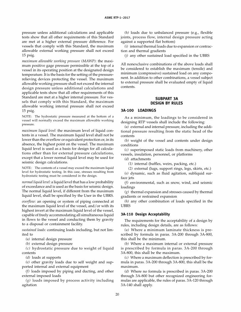
ASME RTP-1–2017
pressure unless additional calculations and applicabletests show that all other requirements of this Standardare met at a higher external pressure difference. Forvessels that comply with this Standard, the maximumallowable external working pressure shall not exceed15 psig.
maximum allowable working pressure (MAWP): the maxi-mum positive gage pressure permissible at the top of avessel in its operating position at the designated designtemperature. It is the basis for the setting of the pressure-relieving devices protecting the vessel. The maximumallowable working pressure shall not exceed the internaldesign pressure unless additional calculations andapplicable tests show that all other requirements of thisStandard are met at a higher internal pressure. For ves-sels that comply with this Standard, the maximumallowable working internal pressure shall not exceed15 psig.NOTE: The hydrostatic pressure measured at the bottom of avessel will normally exceed the maximum allowable workingpressure.
maximum liquid level: the maximum level of liquid con-tents in a vessel. The maximum liquid level shall not belower than the overflow or equivalent protection or, in itsabsence, the highest point on the vessel. The maximumliquid level is used as a basis for design for all calcula-tions other than for external pressure calculations,except that a lower normal liquid level may be used forseismic design calculations.NOTE: The contents of a vessel may exceed the maximum liquidlevel for hydrostatic testing. In this case, stresses resulting fromhydrostatic testing must be considered in the design.
normal liquid level: a liquid level that has a low probabilityof exceedance and is used as the basis for seismic design.The normal liquid level, if different from the maximumliquid level, shall be specified by the User in the UBRS.
overflow: an opening or system of piping connected atthe maximum liquid level of the vessel, and/or with itshighest invert at the maximum liquid level of the vessel,capable of freely accommodating all simultaneous liquidin flows to the vessel and conducting them by gravityto a disposal or containment facility.
sustained loads: continuing loads including, but not lim-ited to
(a) internal design pressure(b) external design pressure(c) hydrostatic pressure due to weight of liquid
contents(d) loads at supports(e) other gravity loads due to self weight and sup-
ported internal and external equipment(f) loads imposed by piping and ducting, and other
external imposed loads(g) loads imposed by process activity including
agitation
20
(h) loads due to unbalanced pressure (e.g., flexiblejoints, process flow, internal design pressure actingagainst a supported flat bottom)
(i) internal thermal loads due to expansion or contrac-tion and thermal gradients
(j) any other sustained load specified in the UBRS
All nonexclusive combinations of the above loads shallbe considered to establish the maximum (tensile) andminimum (compressive) sustained load on any compo-nent. In addition to other combinations, a vessel subjectto external pressure shall be evaluated empty of liquidcontents.
SUBPART 3ADESIGN BY RULES
3A-100 LOADINGS
As a minimum, the loadings to be considered indesigning RTP vessels shall include the following:
(a) external and internal pressure, including the addi-tional pressure resulting from the static head of thecontents
(b) weight of the vessel and contents under designconditions
(c) superimposed static loads from machinery, othervessels, insulation, personnel, or platforms
(d) attachments(1) internal (baffles, weirs, packing, etc.)(2) external (lugs, support rings, legs, skirts, etc.)
(e) dynamic, such as fluid agitation, subliquid sur-face jets
(f) environmental, such as snow, wind, and seismicloadings
(g) thermal expansion and stresses caused by thermalgradients or restrained expansion
(h) any other combination of loads specified in theUBRS
3A-110 Design Acceptability
The requirements for the acceptability of a design byrules, including design details, are as follows:
(a) Where a minimum laminate thickness is pre-scribed by formula in paras. 3A-200 through 3A-800,this shall be the minimum.
(b) Where a maximum internal or external pressureis prescribed by formula in paras. 3A-200 through3A-800, this shall be the maximum.
(c) Where a maximum deflection is prescribed by for-mula in paras. 3A-200 through 3A-800, this shall be themaximum.
(d) Where no formula is prescribed in paras. 3A-200through 3A-800 but other recognized engineering for-mulas are applicable, the rules of paras. 3A-120 through3A-140 shall apply.

ASME RTP-1–2017
3A-120 Other Formulas
Details of design and construction for which no rule isprovided in Subpart 3A, but for which other recognizedengineering formulas exist, may be accepted by compar-ing calculated laminate stress with ultimate laminatestrength to establish a minimum design factor.
3A-121 Laminate Types. Other recognized engi-neering formulas are applicable to Type I or II laminates,laminates in accordance with Subpart 2B, or combina-tions of Types I and II. Other combinations, e.g., Type IIwith laminates in accordance with Subpart 2B, requireadditional consideration. Laminate design strengths areapplicable to reinforcement patterns continuing in theplane of the membrane.
3A-122 Design Factors. The minimum design fac-tors applied to ultimate strength-based design shall be1⁄10 for sustained loads and combinations of sustainedloads, and 1⁄5 for intermittent (short-term) loads takenindividually and in combination with sustained loads.
3A-123 Loadings. Loadings to be consideredinclude those listed in para. 3A-100.
3A-124 Laminate Strengths. Laminate tensilestrength and flexural strength are as established inSubpart 2A. Ultimate secondary bond shear stress isconsidered to be 2,000 psi. Ultimate peel strength isconsidered to be 500 lb/in.
3A-125 Filament Wound Laminates. For design inaccordance with this section, the ultimate hoop tensilestrength of filament wound laminates wound at an angleof 54 deg or higher to the mandrel may be determinedby testing or taken to be 0.01 times the calculated hooptensile modulus. Axial tensile and flexural strength offilament wound laminates shall be established bytesting.
3A-126 Combined Stress. Combined flexural andmembrane stresses shall comply with the following rule:
�mc
St+
�fc
Sf≤
1F10
and
�mi
St+
�fi
Sf≤
1F5
whereF5 p design factor
p 5 for intermittent loadsF10 p design factor
p 10 for sustained loadsSf p ultimate flexural strengthSt p ultimate tensile strength
�fc p calculated maximum sustained flexural stress�fi p calculated maximum intermittent flexural
stress
21
�mc p calculated maximum sustained membranestress
�mi p calculated maximum intermittent membranestress
3A-127 Recognized Formulas. Other recognized for-mulas include stress calculations presented in varioussections of the ASME pressure vessel codes, formulasincluded in the nonmandatory appendices of thisStandard, and well-documented formulas presentedelsewhere.
3A-130 Maximum Corrosion-Resistant Barrier Strain
In addition to the stress criteria listed above, the ten-sile strain in the corrosion-resistant barrier shall be lim-ited to the following:
(a) for sustained loads: 0.0013 for resins for which thetensile elongation of the cast resin is at least 4%, and0.0010 for all other resins. Elongation of the resin shallbe determined in accordance with ASTM D638 at 77°F.
(b) for intermittent loads: 0.0020.
3A-140 Maximum Compressive Stress Stability
In addition to the stress criteria listed above, for allloading conditions and combinations (including exter-nal pressure) that result in compressive loads in a shell,the stress shall be limited to one-fifth of the criticalbuckling stress.
3A-150 Conservative Design
Where the application of para. 3A-110(d) indicates aless-conservative design than paras. 3A-110(a), (b), or(c), additional justification shall be provided beforeusing the less-conservative design.
3A-200 DESIGN FOR TOTAL INTERNAL PRESSURE
3A-210 Calculation of Minimum Thickness ofCylindrical Shells
(a) Contact molded construction is calculated asfollows:
Hoop Loading Axial Loading
th pPDi
2Sh /Fta p
Nax
Sa/F
whereDi p inside diameter, in.F p design factor p 10
Nax p axial force per circumferential inch of shell,lb/in.
P p total internal pressure, psig (internal pressureplus hydrostatic head)
Sa p ultimate axial tensile strength, psiSh p ultimate hoop tensile strength, psita p total wall thickness, in., for axial stressth p total wall thickness, in., for circumferential
stress
Get more FREE standards from Standard Sharing Group and our chats

ASME RTP-1–2017
The shell thickness shall be the greater of ta or th atthe point considered by the calculation.
(b) Filament wound construction is calculated asfollows:
Hoop Loading Axial Loading
th pPDi
2(0.001Eh)ta p
Nax
Sa/F
or
th pPDiF2Sh
ta pNaxF
Sa
NOTE: Corrosion-resistant barrier strain shall not exceed limitsin para. 3A-130.
whereEh p hoop tensile modulus
The shell thickness shall be the greater of ta or th atthe point considered by the calculation.
3A-220 Design of Cylindrical Shells Under CombinedAxial Loads
3A-221 Tensile Loads. The thickness of shells undercombined axial tensile loads shall be equal to the largestvalue for t as calculated below:
(a) Shells under internal pressure shall meet therequirements of para. 3A-210.
(b) For shells under combined axial tensile designloads, t shall be calculated as follows:
t pMA
�(D/2)2(Sa/F)+
FA
�D(Sa/F)+
PD4(Sa/F)
whereD p inside diameter, in.F p design factor p 10
FA p axial tensile force resulting from designloads, lb
MA p bending moment resulting from design loads,in.-lb
P p internal pressure, psiSa p ultimate axial tensile strength, psi
(c) For shells under combined axial tensile loadsresulting from design loads, including wind, snow, orseismic loads, t shall be calculated as follows:
t p�MA� + �MB�
�(D/2)2(Sa/F)+
FA + FB
�D(Sa/F)+
PD4(Sa/F)
whereF p design factor p 5
FB p axial tensile force resulting from wind, snow,or seismic loads, lb
MB p bending moment resulting from wind, snow,or seismic loads, in.-lb
22
3A-222 Compressive Loads. The thickness of shellsunder combined axial compressive loads shall be equalto the largest value for t as calculated below.
(a) Shells under external pressure shall meet therequirements of para. 3A-310.
(b) For shells under combined axial compressivedesign loads, t shall be the greater of t1 or t2 calculatedas follows:
t1 p�MA�
�(D/2)2(Sa/F1)+
�FA��D(Sa/F1)
+PeD
4(Sa/F1)
t2 p �� �MA�
�(D/2)2+�FA��D
+PeD
4 � F2(D/2)0.3Eeff �
0.5
whereD p inside diameter, in.
Eaf p axial flexural modulus, psiEeff p (EafEht)0.5
Eht p hoop tensile modulus, psiFA p axial compressive force resulting from design
loads, lbF1 p design factor p 10F2 p design factor p 5
MA p bending moment resulting from design loads,in.-lb
Pe p external pressure, psiSa p ultimate axial tensile strength, psi
(c) For shells under combined axial compressive loadsresulting from design loads and occasional loads, includ-ing wind, snow, or seismic loads, t shall be the greaterof t1 or t2 calculated as follows:
t1 p�MA� + �MB�
�(D/2)2(Sa/F1)+�FA� + �FB��D(Sa/F1)
+PeD
4(Sa/F1)
t2 p ���MA� + �MB�
�(D/2)2+�FA� + �FB�
�D+
PeD4 � F2(D/2)
0.3Eeff �0.5
whereFB p axial compressive force resulting from wind,
snow, or seismic loads, lbF1 p design factor p 5F2 p design factor p 5
MB p bending moment resulting from wind, snow,or seismic loads, in.-lb
3A-230 Minimum Thickness of Torispherical Heads
The minimum thickness, t, of torispherical heads shallbe calculated as follows:
t pMPRc
2(Su/F)
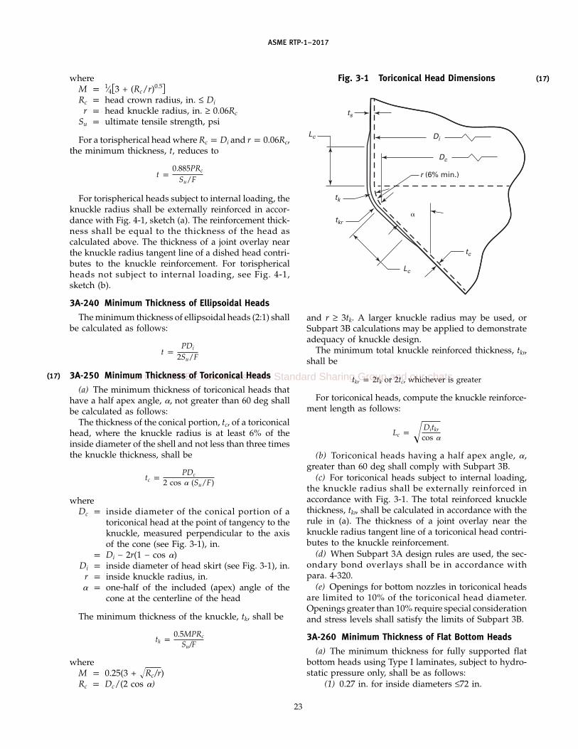
(17)
ASME RTP-1–2017
whereM p 1⁄4�3 + (Rc/r)0.5�Rc p head crown radius, in. ≤ Di
r p head knuckle radius, in. ≥ 0.06RcSu p ultimate tensile strength, psi
For a torispherical head where Rc p Di and r p 0.06Rc,the minimum thickness, t, reduces to
t p0.885PRc
Su/F
For torispherical heads subject to internal loading, theknuckle radius shall be externally reinforced in accor-dance with Fig. 4-1, sketch (a). The reinforcement thick-ness shall be equal to the thickness of the head ascalculated above. The thickness of a joint overlay nearthe knuckle radius tangent line of a dished head contri-butes to the knuckle reinforcement. For torisphericalheads not subject to internal loading, see Fig. 4-1,sketch (b).
3A-240 Minimum Thickness of Ellipsoidal Heads
The minimum thickness of ellipsoidal heads (2:1) shallbe calculated as follows:
t pPDi
2Su/F
3A-250 Minimum Thickness of Toriconical Heads
(a) The minimum thickness of toriconical heads thathave a half apex angle, �, not greater than 60 deg shallbe calculated as follows:
The thickness of the conical portion, tc, of a toriconicalhead, where the knuckle radius is at least 6% of theinside diameter of the shell and not less than three timesthe knuckle thickness, shall be
tc pPDc
2 cos � (Su/F)
whereDc p inside diameter of the conical portion of a
toriconical head at the point of tangency to theknuckle, measured perpendicular to the axisof the cone (see Fig. 3-1), in.
p Di − 2r(1 − cos �)Di p inside diameter of head skirt (see Fig. 3-1), in.
r p inside knuckle radius, in.� p one-half of the included (apex) angle of the
cone at the centerline of the head
The minimum thickness of the knuckle, tk, shall be
tk p0.5MPRc
Su/F
whereM p 0.25(3 + Rc/r)Rc p Dc/(2 cos �)
23
Fig. 3-1 Toriconical Head Dimensions
ts
Di
Dc
r (6% min.)
Lc
tk
tkr
Lc
tc
�
and r ≥ 3tk. A larger knuckle radius may be used, orSubpart 3B calculations may be applied to demonstrateadequacy of knuckle design.
The minimum total knuckle reinforced thickness, tkr,shall be
tkr p 2tk or 2tc, whichever is greater
For toriconical heads, compute the knuckle reinforce-ment length as follows:
Lc p Ditkr
cos �
(b) Toriconical heads having a half apex angle, �,greater than 60 deg shall comply with Subpart 3B.
(c) For toriconical heads subject to internal loading,the knuckle radius shall be externally reinforced inaccordance with Fig. 3-1. The total reinforced knucklethickness, tkr, shall be calculated in accordance with therule in (a). The thickness of a joint overlay near theknuckle radius tangent line of a toriconical head contri-butes to the knuckle reinforcement.
(d) When Subpart 3A design rules are used, the sec-ondary bond overlays shall be in accordance withpara. 4-320.
(e) Openings for bottom nozzles in toriconical headsare limited to 10% of the toriconical head diameter.Openings greater than 10% require special considerationand stress levels shall satisfy the limits of Subpart 3B.
3A-260 Minimum Thickness of Flat Bottom Heads
(a) The minimum thickness for fully supported flatbottom heads using Type I laminates, subject to hydro-static pressure only, shall be as follows:
(1) 0.27 in. for inside diameters ≤72 in.
(17)
Get more FREE standards from Standard Sharing Group and our chats

ASME RTP-1–2017
(2) 0.31 in. for inside diameters >72 in. to ≤96 in.(3) 0.40 in. for inside diameters >96 in. to
≤144 in.(4) See (c) for diameters over 144 in.
(b) The minimum thickness for fully supported flatbottom heads using Type II laminates, subject to hydro-static pressure only, shall be as follows:
(1) 0.22 in. for inside diameters ≤72 in.(2) 0.29 in. for inside diameters >72 in. to ≤96 in.(3) 0.37 in. for inside diameters >96 in. to
≤144 in.(4) See (c) for diameters over 144 in.
The thicknesses given in (1), (2), and (3) above haveproven adequate to prevent damage during normal con-ditions associated with fabrication, handling, shipping,and installation.
(c) For inside diameters that exceed 144 in., designanalysis shall be undertaken to establish a bottom thick-ness that will withstand the conditions in (b) abovewithout resultant damage.
(d) The radius of the bottom knuckle of a flat bottomvessel shall not be less than 1 in. if the diameter is 4 ftor less, and 11⁄2 in. for diameters exceeding 4 ft. Theminimum thickness of the radius section shall be equalto the combined thickness of the shell wall and the bot-tom. The reinforcement of the knuckle radius area shalltaper so that it is tangent with the flat bottom and shallnot extend beyond the tangent line onto the tank bottom.The knuckle reinforced area shall extend for a minimumdistance of 8 in. from the inside tank bottom up thevertical wall for tanks up to and including 4 ft in diame-ter, and 12 in. for tanks over 4 ft in diameter. The rein-forcement shall then taper into the side wall for anadditional length of 4 in. (see Fig. 4-2). The perimeterof the tank bottom shall be a flat plane, and the bottomshall not have any projections that exceed 1⁄4 in. and thatwill prevent uniform contact with a flat support surfacewhen the tank is filled with liquid. While Fig. 4-2,sketches (a) and (d), show a joint line, it is permissibleto fabricate the head integral with the shell (no jointrequired). This method of manufacture requires rein-forcement of the knuckle radius area as described above[see Fig. 4-2, sketch (c)].
(e) The design of flat heads that are unsupported bya foundation over their entire flat surface or are loadedby external pressure is not included in Subpart 3A. Suchdesigns may be carried out using Subpart 3B rules. SeeNonmandatory Appendix NM-13.
(f) The design of flat heads that are supported by afoundation over the entire flat surface and are loadedby internal pressure requires the use of hold-down lugsto prevent the vessel from lifting. The lugs and theknuckle shall be designed to withstand the momentsinduced because of uplift in addition to the other loads.The design factor for RTP components shall be 10 forpressure loading or 5 for pressure combined with wind,
24
seismic, and other temporary loads, whichever governs.The size and number of the anchor bolts are part of thehold-down design. The depth and attachment of theanchor bolts to the concrete foundation, as well as theintegrity of the foundation, are not considered part ofthe scope.
3A-261 Flat-Bottom Knuckle Design(a) The flat-bottom knuckle details displayed in
Fig. 4-2 are empirically based and suitable for shop fabri-cated tanks. These details may be used in lieu of acalculation-based design for tanks up to 16 ft indiameter.
(b) When the Fabricator elects to use a knuckle detailthat differs from Fig. 4-2, the knuckle must be designedby calculation.
(c) For tanks 16 ft in diameter and above, the bottomknuckle must be designed by calculation.
(d) Knuckle design calculations must account for liq-uid pressure, design pressure uplift, foundation contact,knuckle thickness and radius, and discontinuitiesresulting from the knuckle-to-shell connection. A calcu-lation method that may be used is axisymmetric finiteelement design with contact elements. The design crite-ria is strength-based for contact molded laminates andstrain-based for filament wound laminates. For continu-ous loading, the design factors shall be 10 and0.001 in./in. hoop direction, filament hoop laminates.For intermittent loading, the factors in para. 3A-440 shallbe used.
(e) The Professional Engineer is responsible for recog-nizing the limitations of Fig. 4-2 details and should givespecial consideration to tall tanks, high specific gravitycontents, high design pressure, and combinationsthereof.
3A-270 Minimum Thickness of Hemispherical Heads
For hemispherical heads under internal pressure,compute the minimum thickness, t, as follows:
t p PRs/2Sa
whereP p design internal pressure, psi
Rs p inside radius of head, in.Sa p allowable stress, psi
3A-300 DESIGN FOR EXTERNAL PRESSURE
3A-310 Cylindrical Shells
The maximum allowable external pressure betweenstiffening elements is computed by the following:
Pa pKD(0.853)�E3/4
hf E1/4at t5/2
(1 − �ah�ha)3/4L(Do/2)3/2FS

ASME RTP-1–2017
whereDo p outside diameter of shell, in.Eaf p axial flexural modulus, psiEat p axial tensile modulus, psiEhf p hoop flexural modulus, psiFS p design factor of safety p 5
KD p 0.84, a knockdown factorp 1.0 for Type I and Type II laminates
L p design length of a vessel section, in., taken asthe largest of the following:
(a) the distance between head-tangent linesplus one-third the depth of each formed head,if there are no stiffening rings (excluding coni-cal heads and sections)
(b) the distance between cone-to-cylinderjunctions for vessels with cone or conicalheads, if there are no stiffening rings
(c) the greatest center-to-center distancebetween any two adjacent stiffening rings
(d) the distance from the center of the firststiffening ring to the formed head tangent lineplus one-third the depth of the formed head(excluding conical heads and sections), allmeasured parallel to the axis of the vessel
(e) the distance from the first stiffening ringin the cylinder to the cone-to-cylinder junction
Pa p allowable external pressure, psit p wall thickness, in. (nominal)
Zp pE3/2
hf E1/2at
E2af
(1 − �ah�ha)1/2 L2
(Do/2)t
� p reduction factor developed to better correlatetheoretical predictions and test results
p 1 − 0.001Zp if Zp ≤ 100p 0.9 if Zp > 100
�ah p flexural Poisson’s ratio in the axial direction≈ −S54/S44, where S54 and S44 are terms in theinverted form of the laminate ABD stiffnessmatrix, Sij (see para. M3-520)
�ha p flexural Poisson’s ratio in the hoop direction≈ −S45/S55
NOTES:(1) For design without calculating the Poisson’s ratios, the follow-
ing apply:(a) Type I Laminates. For an all Type I laminate, the flexural
and in-plane Poisson’s ratios for axial and hoop are identical.Setting these to zero produces about a 9% reduction in allow-able pressure.
(b) Type II Laminates. For all Type II laminates with no liner,the flexural and in-plane Poisson’s ratios are slightly differentdue to the 5/4 weave. Setting these to zero produces about a5% reduction in allowable pressure. Setting the flexural andin-plane Poisson’s ratio equal to the in-plane Poisson’s ratiosproduces a <1% reduction in allowable pressure for standardType II laminates. Any number of chopped strand mat pliesmay be added to the Type II laminate, so in the limit of aninfinite number of Type I plies, the setting of the Poisson’s ratiosto zero produces the same result as the Type I laminates above.
25
(c) Type X Laminates. For Type X laminates, the Poisson’sratios need to be calculated per laminate analysis or deter-mined by testing.
(2) Nonmandatory Appendix NM-16 provides an example of theNASA SP-8007 solution for lateral and longitudinal pressure.
3A-320 Torispherical and Elliptical Heads
For torispherical heads, compute the allowable exter-nal pressure, Pa, as follows:
Pa p 0.36(Ef/F)(t/Ro)2
For torispherical heads, compute the minimum thick-ness, t, as follows:
t p Ro(FPd/0.36Ef)0.5
For elliptical heads, compute the allowable externalpressure, Pa, as follows:
Pa p 0.36(Ef/F)(t/KoDoh)2
For elliptical heads, compute the minimum thickness,t, as follows:
t p KoDoh(FPd/0.36Ef)0.5
whereDoh p outside diameter of head, in.
Ef p flexural modulus of elasticity for head, psiKo p factor depending on ellipsoidal head propor-
tions as follows:
Major to MinorAxis Ratio Ko
2.0 0.901.8 0.811.6 0.731.4 0.651.2 0.571.0 0.50
Pa p allowable external pressure, psiPd p design external pressure, psiRo p outside crown radius of head, in.
3A-330 Stiffening Rings
The required moment of inertia, Is, of a circumferentialstiffening ring, including the effective length of the shelland the added stiffener ring, for cylindrical shells underexternal pressure or internal vacuum shall not be lessthan that determined by the following formula:
Is p PLsD3oF/24Eh
whereDo p shell outside diameter, in.Eh p effective hoop modulus of shell and stiffener,
psi
Get more FREE standards from Standard Sharing Group and our chats

ASME RTP-1–2017
F p design factor p 5Ie p the calculated effective moment of inertia, in.4,
considering the different moduli of the shelland stiffener and the resulting shift in neutralaxis. Ie shall be greater than or equal to Is.
Is p moment of inertia, in.4, of stiffener and effectivelength of shell. The effective length of shellshall not be greater than the length of the shellunder the ring plus no more than the lengthof the bending boundary layer (BBL) in theshell where the stresses are 50% of the peakvalues on each side of the centroid of the ring.See Nonmandatory Appendix NM-17 for theBBL formulation. Portions of shell shall not beconsidered as contributing to more than onestiffening ring.
Ls p one-half of the distance from the centerline ofthe stiffening ring to the next line of supporton one side, plus one-half of the centerline dis-tance to the next line of support on the otherside of the stiffening ring, both measured paral-lel to the axis of the cylinder, in. A line ofsupport is
(a) a stiffening ring that meets the require-ments of this paragraph
(b) a circumferential line on a head at one-third the depth of the head from the head tan-gent line
(c) a cone-to-cylinder junctionP p actual external pressure, psi
See Fig. 4-7 for stiffener details and NonmandatoryAppendix NM-17 for example calculations. Other stif-fener profiles meeting the required moment of inertiamay be used.
3A-340 Top Head Loads
The top head, regardless of shape, shall be designedto support a 250 lb load on a 16 in.2 compact area withoutdamage and with a maximum deflection of 0.5% of theshell diameter, or 0.5 in., whichever is less. For torispher-ical heads, this requirement can be satisfied by using themethod presented in Nonmandatory Appendix NM-11.
3A-345 Fully Supported Flat-Bottom Heads Subjectto External Pressure. Flat-bottom heads shall bedesigned so that, when subject to the external pressure(s)
(a) calculated stresses in the head do not exceed(1) one-tenth of the ultimate strength(s) of the lami-
nates employed for sustained loads(2) one-fifth of the ultimate strength(s) of the lami-
nates employed for intermittent loads combined withsustained loads and
(b) upward deflection of the flat bottom resultingfrom the external load will not exceed 11⁄2% of the diame-ter of the head for all external loading conditions
26
Liquid contents of the vessel shall not be consideredto reduce stresses or deflection.
NOTE: Where rigid internal equipment is fitted on or close tothe bottom, a lower deflection limit may be required.
3A-350 Toriconical Heads
(a) For toriconical heads whose half apex angle, �,is ≤60 deg, the maximum allowable external pressurebetween stiffening elements is computed by thefollowing:
Pa pK(Erc/F)(Do/L)[(tc cos �)/Do]2.5
1 − 0.45[(tc cos �)/Do]0.5
Also check for stress in the cone, Sc, as follows:
Sc pPdDc
2tc cos �
The stress, Sc, must not exceed Su/F.For toriconical heads, compute the knuckle reinforce-
ment length as follows:
Lc p Ditkr
cos �
The thickness of the knuckle, tk, shall be
tk p0.5MPdRc
Su/F
The minimum total knuckle reinforced thickness, tkr,shall be
tkr p 2tk or 2tc, whichever is greater
whereDc p inside diameter of the conical portion of a
toriconical head at the point of tangency to theknuckle, measured perpendicular to the axisof the cone (see Fig. 3-1), in.
p Di − 2r(1 − cos �)Do p maximum outside diameter at the large end
of the conical segment between stiffening ele-ments (see Fig. 3-2), in.
Eac p axial tensile modulus for the cone, psiEhc p hoop tensile modulus for the cone, psiErc p resultant modulus for the cone, psi
p (EacEhc)0.5
F p design factor p 5K p 4 − 0.75(Erc/1,000,000)L p conical segment slant height (see Fig. 3-2), in.
M p 0.25(3 + Rc/r)Pa p allowable external pressure, psiPd p design external pressure, psiRc p Dc/(2 cos �)
r p inside knuckle radius (see Fig. 3-1), in.(6% minimum and at least three times theknuckle thickness)
(17)

(17)
ASME RTP-1–2017
Fig. 3-2 Toriconical Head Dimensions for External Pressure
Do
Ls
L�
Su p ultimate tensile strength, psitc p cone thickness (see Fig. 3-1), in.tk p knuckle thickness (see Fig. 3-1), in.
tkr p total reinforced knuckle thickness (seeFig. 3-1), in.
� p one-half the apex angle in toriconical headsand sections (see Fig. 3-1), deg
(b) When the half apex angle � exceeds 60 deg, thetoriconical head shall be designed in accordance withSubpart 3B.
(c) For toriconical heads subject to external pressure,the knuckle radius shall be externally reinforced inaccordance with Fig. 3-1. The total reinforced knucklethickness tkr shall be calculated in accordance with therule in (a). The thickness of a joint overlay near theknuckle radius tangent line of a toriconical head contri-butes to the knuckle reinforcement.
(d) When Subpart 3A design rules are used, the sec-ondary bond overlays shall be in accordance withpara. 4-320.
3A-360 Stiffening Rings
The required moment of inertia, Is, of a circumferentialstiffening ring for conical shells under external pressure
27
shall not be less than that determined by the followingformula:
Is pPdLs(Do/cos �)3F
24Ehs
whereEhs p hoop tensile modulus for the stiffening ring,
psiLs p one-half of the conical segment slant distance
from the centerline of the stiffening ring to thenext line of support on one side, plus one-halfof the conical segment slant distance from thecenterline of the stiffening ring to the next lineof support on the other side (see Fig. 3-2), in.A line of support is
(a) a stiffening ring that meets the require-ments of this paragraph
(b) a toriconical head-to-cylinder junction(c) apex of a toriconical head
3A-400 SEISMIC, WIND, AND SNOW LOADINGS
3A-410 Design Loadings
The loadings to be considered in designing vesselsshall include seismic loads, wind loads, and snow loads,
(17)
Get more FREE standards from Standard Sharing Group and our chats
ASME RTP-1–2017
determined by vessel installation, location, and cus-tomer specification as defined in the UBRS. The effectsof liquid sloshing in large vessels shall be considered.The design shall be certified by a qualified registeredProfessional Engineer experienced in the design of rein-forced plastics.
3A-420 Specifying Design Loadings
The magnitude and orientation of the forces enumer-ated in para. 3A-410 shall be as specified by the UBRS(see para. 1-200). Examples of codes and design calcula-tions are shown in Nonmandatory Appendix NM-3.
3A-430 Assumed Design Loadings
The vessel design shall be analyzed under the follow-ing loading combinations:
(a) sustained loads plus seismic load(b) sustained loads plus snow load(c) sustained loads plus wind load(d) wind loads on an empty vesselSeismic, wind, and snow loads are considered to act
separately. The forces are not cumulative.
3A-440 Stresses From Loadings
Stresses produced by seismic, wind, or snow loading,in conjunction with any appropriate working stresses,shall be less than Su/5, a design factor of 5 for contactmolded construction. For filament wound construction,the hoop strain shall be less than 0.002 in./in. and theaxial stress shall be less than Su/5.
3A-450 Loading Design Examples
Examples of wind and snow load design are given inNonmandatory Appendix NM-3. The wind load calcula-tions are for static loading only and do not consider theeffect of stress buildup due to resonant vibrations, whichmay be a factor in tall structures. These examples aregiven to illustrate the extent of analysis necessary toverify the resistance of equipment to these loads. Othermethods of analysis may be used, provided that all ofthe stresses induced by these loads are considered andsatisfy the requirements of Part 3.
3A-460 Hold-Down Lugs
3A-461 General. Concentrated loadings resultingfrom hold-down lugs shall be calculated. A designmethod for hold-down lugs is given in NonmandatoryAppendix NM-4. When hold-down lugs are attached inthe shop or in the field, the attachment of the hold-downlugs shall be performed by secondary bonders qualifiedin accordance with Mandatory Appendix M-5, and thevessel pressure test per para. 6-950 shall be performedafter the attachment of the lugs. Final inspection perpara. 6-900 shall be completed after the hold-down lugattachment and testing have been completed. The
28
Fabricator retains overall responsibility for all fieldwork, testing, and inspection.
The hold-down lug shall be parallel to and above thedatum plane for flat-bottom vessels as shown in Fig. 4-9.Nonmandatory Appendix NM-4 suggests a minimumdimension of 1⁄2 in. between the datum plane and thebottom of the hold-down lug.
3A-462 Containment Area Flood Loading on Hold-Down Lugs
(a) When flooding is designated in the UBRS, hold-down lugs shall be designed to withstand uplift forcesfrom flooding of the containment area.
(b) When the UBRS specifies that the bottom headand shell are not to be designed to withstand flooding ofthe containment area, the vessel nameplate or a separatelabel shall contain the following statement: “Bottomhead and shell not designed for flooding of the contain-ment area. Containment area flooding may result indamage and vessel leaks. Vessel must be inspectedbefore being returned to service if containment area isflooded.”
3A-500 LARGE DIAMETER RTP EQUIPMENT BODYFLANGES
A method for designing flanges with full-face gasketsis given in Nonmandatory Appendix NM-2. Dimensionsand allowable pressures for representative flanges withfull-face gaskets are given in Table NM2-1. The maxi-mum allowable design stress value shall be 3,000 psi forflanges constructed of Type II laminates and 1,800 psifor flanges constructed of Type I laminates.
3A-600 VESSELS SUPPORTED BY SHELLATTACHMENTS
Where the vessel is supported by attachments to theshell, the attachments and associated reinforcement shallbe designed to avoid exceeding allowable stresses bothin the attachments and the shell. Attachments may befabricated from RTP or metal as agreed upon by theUser and the Fabricator.
The use of support lugs for vertical cylindrical vesselsrequires consideration of the forces caused by eccentricloading of the lugs. In small vessels, these radial forcesmay be accommodated by reinforcement of the shell. Invessels larger than 3 ft inside diameter, some type ofa metallic ring–lug support should be used. A designmethod for metallic ring–lug supports is presented inNonmandatory Appendix NM-5.
3A-700 REINFORCEMENT OF CIRCULAR OPENINGS
(a) Openings cut in cylindrical shells and heads forinstallation of nozzles and manways shall be reinforcedby a circular area concentric with the cutout shown in

ASME RTP-1–2017
Figs. 4-4 and 4-5. Required patterns of reinforcementplacement are shown in Fig. 4-12.
(b) Only circular openings whose diameter does notexceed one-half of the vessel diameter are covered bythese rules. Openings of other geometries and openingswhose diameter exceeds one-half of the vessel diameterrequire special consideration and stress levels shall sat-isfy the limits of Subpart 3B.
(c) For circular nozzles, only openings with the largestdimension along one axis being no longer than twotimes the largest dimension along the axis 90 deg to thefirst axis are covered by these rules. These dimensionsshall be measured from one cut edge to the oppositecut edge (the chord is measured in the hoop direction).
(d) These rules only cover reinforcement of cylindersand dished, elliptical, or conical heads using the thick-ness equations shown in Subpart 3A.
3A-710 Wall Thickness Definitions
Ta p actual structural wall thickness, in.p wall thickness obtained after fabrication, not
including any sacrificial corrosion barrierTc p calculated structural wall thickness, in.
p wall thickness planned on being used to fabri-cate the vessel; calculated by summing the theo-retical thickness of each layer, not including anysacrificial corrosion barrier
Tt p theoretical structural wall thickness, in.p minimum wall thickness that will satisfy the
design conditions; does not include sacrificialcorrosion barrier if it is specified
EXAMPLE: The design calculations establish that the wall thick-ness shall be at least 0.242 in. (Tt). A 0.29-in. (Tc) wall thickness isspecified for fabrication. After fabrication, it is determined to be0.322 in. (Ta).
D p vessel inside diameter, in.d p nozzle’s largest hole dimension, in.K p 1 for nozzles ≥6 in.
p d/6 for nozzles <6 in.M p 1 for Type I or II laminates
p �/15,000 for Type X laminatesT p vessel wall thicknesst p nozzle wall thickness
tr p reinforcement thickness, in.V p 1 for internal pressure
p 1⁄2 for external pressure� p hoop tensile ultimate strength for cylinders, psi
p tensile ultimate strength for heads, psi
3A-720 Reinforcement Diameter
The outer diameter of the opening reinforcing lami-nate, dr, shall not be less than two times the opening’slargest dimension. For openings with largest dimensionless than 6 in., the minimum opening reinforcementdiameter, dr, shall be the largest dimension plus 6 in.
29
The reinforcing diameters, dr, of two openings shallnot overlap.
3A-730 Reinforcement Thickness
(a) Reinforcing materials shall always be Type II,except Type I reinforcing can be used on Type Ilaminates.
(b) Ta over and above Tc shall not be considered tohave reinforcing value.
(c) When tr < 0.129, no reinforcing is required.(d) tr p VMKTt − M(Tc − Tt).(e) Opening reinforcement thickness that must be
added to the wall may be applied to the outer or innersurfaces, or be divided between them as shown inFig. 4-12. Beyond the limits of dr, the added openingreinforcement thickness shall be tapered onto the shellat not less than 1:6.
3A-800 SECONDARY BOND SHEAR STRESS
The ultimate secondary bond shear stress is 2,000 psi.
SUBPART 3BDESIGN BY STRESS ANALYSIS
3B-100 INTRODUCTION
Either vessel or vessel part may be designed usingthe stress analysis methods listed in this subpart. TheSubpart 3B design process consists of two steps: (1) thebiaxial stress analysis shall be performed at points ofconcern as determined by the design ProfessionalEngineer, and (2) the stress analysis results of the vesselor vessel part shall fall within the limits established bypara. 3B-500.
Various methods may be used to determine the biaxialstress state in the laminate. These methods are
(a) the stress analysis methods of NonmandatoryAppendix NM-13 that are adapted from Section VIII,Division 2 of the ASME Boiler and Pressure Vessel Code
(b) the finite element method(c) closed form solutions that yield the complete biax-
ial state of stress(d) back calculation of the biaxial state of stress using
strain gage data(e) other mathematical and/or experimental tech-
niques, provided they are as accurate or as conservative,in the opinion of the design Professional Engineer, indetermining the biaxial state of stress as those listedabove
The stress criteria are different because of the brittlebehavior of RTP compared with steel and other ductilemetals, and because of the anisotropic behavior of fila-ment wound and other laminates containing continuousroving.
Get more FREE standards from Standard Sharing Group and our chats

ASME RTP-1–2017
3B-200 DESIGN ACCEPTABILITY
The requirements for the acceptability of a design are(a) the design shall be such that the stress shall not
exceed the limits described in the stress criteria inpara. 3B-500
(b) for configurations that involve external pressureor other loads defined in para. 3B-300, the load shallnot exceed one-fifth of the critical buckling load
3B-210 Basis for Determining Stresses
The equivalent stress ratio at any point in a vessel is thevalue of stress ratio deduced from the stress condition atthe point by means of a theory of failure. The theory offailure used in the rules of this subpart for combiningstresses is the quadratic interaction criterion. It is appli-cable to the most general combination of isotropic andanisotropic lamina allowed by this Standard. The stressanalysis and evaluation shall include the directionalproperties of the laminate and individual lamina andshall take into account the primary and secondarystresses caused by gross structural discontinuities.
3B-220 Terms Relating to Stress Analysis
Terms used in this subpart relating to stress analysisare defined as follows:
(a) Gross Structural Discontinuity. A gross structuraldiscontinuity is a source of stress or strain intensificationthat affects a relatively large portion of a structure andhas a significant effect on the overall stress or strainpattern or on the structure as a whole.
Examples of gross structural discontinuities are head-to-shell and body-flange-to-shell junctions, and junc-tions between shells of different diameters orthicknesses.
(b) Load Stress. A load stress is a stress that resultsfrom the application of a load, such as internal pressureor the effects of gravity, as distinguished from thermalstress.
(c) Local Primary Membrane Stress. Cases arise inwhich a membrane stress produced by pressure or othermechanical loading and associated with a primaryand/or a discontinuity effect would, if not limited, pro-duce excessive distortion in the transfer of load to otherportions of the structure. Such stresses are termed localprimary membrane stress.
An example of a local primary membrane stress is themembrane stress in the shell produced by external loadand moment at a permanent support.
(d) Membrane Stress. The membrane stress is definedas the component of normal stress which is uniformlydistributed and equal to the average value of stressacross the thickness of the section under consideration.
(e) Moment Resultant. The intersection of the refer-ence surface and the section under consideration definesan intersection line. The moment resultant is the momentof the normal stress about the intersection line. It is the
30
bending moment per unit length in the laminate. (SeeMandatory Appendix M-3, Fig. M3-1.) The location ofthe reference surface is chosen by the engineer. The refer-ence surface used to define the stress resultants shall bethe same as that used to compute stiffness coefficients.
(f) Normal Force Resultant. The normal force resultantis the resultant force of the normal stresses in all thelamina at the section under consideration.
(g) Normal Stress. The normal stress is the componentof stress normal to the plane of reference. Usually thedistribution of normal stress is not uniform through thethickness of a lamina. The stress is considered to bemade up of two components, one of which is uniformlydistributed and equal to the average value of the stressacross the lamina of the section under consideration,and the other of which varies with the location acrossthe lamina.
(h) Off-Axis Coordinates. The off-axis coordinates arecoordinates chosen by the engineer. They coincide withthe vessel coordinates (see Fig. M3-4).
(i) On-Axis Coordinates. The on-axis coordinates area collection of sets of axes, one for each lamina. Thex-axis of a set is aligned with the reinforcement, and they-axis is perpendicular to the x-axis and lies in the planeof the lamina. The x–y axes or on-axis systems are alsocalled the principal material axis systems (see Fig. M3-4).
(j) Primary Stress. A primary stress is a normal stressor a shear stress developed by the imposed loading. Itis necessary to satisfy the laws of equilibrium of externalor internal forces and moments.
The basic characteristic of a primary stress is that itis not self-limiting. Primary stresses that considerablyexceed the stress at onset of cracking will result in failureor at least in gross distortion. A thermal stress is notclassified as a primary stress.
Examples of primary stress are(1) the general membrane stress in a circular cylin-
drical or a spherical shell due to internal pressure ordistributed live loads
(2) the bending stress in the central portion of aflat head due to pressure
(k) Reference Surface. The reference surface is a surfacethat is parallel to the lowermost surface of the laminate.The distance from the lowermost surface is chosen bythe engineer. Common choices are the surface midwaybetween the outermost and innermost laminate surfacesor the neutral bending surface (see para. M3-200). In thecase of symmetric laminates, these choices coincide.
(l) Shear Force Resultant. The shear force resultant isthe resultant force of the shear stresses in all the laminaat the section under consideration. It is the shear forceper unit length in the plane of the laminate.
(m) Shear Stress. The shear stress is defined as thecomponent of stress tangent to the plane of reference.
(n) Secondary Stress. A secondary stress is a normalstress or a shear stress developed by the constraint of
ASME RTP-1–2017
adjacent parts or by self-constraint of a structure. Thebasic characteristic of a secondary stress is that it is self-limiting. Local inelastic deformation and minor distor-tions can satisfy the conditions which cause the stressto occur.
Examples of secondary stress are(1) general thermal stress(2) bending stress at a gross structural discontinuity
(o) Strength Ratio. The strength ratio is defined as thelowest value by which each component in the stressstate at a point could be multiplied so that the multipliedstress state would violate the failure criterion inpara. 3B-500.
(p) Thermal Stress. A thermal stress is a self-balancingstress produced by a nonuniform distribution of temper-ature or by adjoining parts with different thermal coeffi-cients of expansion. Thermal stress is developed in asolid body whenever a volume of material is preventedfrom assuming the size and shape that it normally wouldunder a change in temperature.
(q) Twisting Moment Resultant. At each point alongthe intersection of the reference surface and a sectionunder consideration, the twisting moment resultant isthe moment of the shear stress about the point (seeFig. M3-1).
(r) Closed Form Solution. A closed form solution is amathematically exact solution or series of equations thataccurately describes the state of stress without beingbased on empirical data.
3B-300 LOADING
All vessels shall be designed to resist the hydrostaticload. Top heads, or other surfaces where personnelmight walk, shall be designed to support a 250-lb loadon a 16-in.2 compact area without exceeding the stresscriteria of para. 3B-500, and with a deflection ≤ 0.5% ofthe vessel diameter or width.
Vessels shall also be designed to withstand the follow-ing load combinations without violating the criterion ofpara. 3B-500. The magnitude of each of the loads isdefined by the UBRS (see para. 1-200) as follows:
(a) internal pressure above the liquid contents, super-posed on the hydrostatic pressure.
(b) loads on support ring or lugs from the vesselweight, the contents weight, and imposed loads.
(c) external pressure.(d) seismic load, which shall be considered as acting
at the same time as the hydrostatic and pressure loads,but not simultaneous with maximum wind loads. Thevessel shall resist the seismic loads without exceedingthe criteria of para. 3B-500, as required by local codes.(See Nonmandatory Appendix NM-3.)
(e) loads from attachments, such as ladder clips, agita-tors, and lifting lugs.
31
(f) loads from internal parts, such as baffles and pack-ing supports.
(g) load on nozzles due to flow forces and pressure(as in the case of manways and other nozzles with blindflanges).
(h) loading that results from thermal expansion, andstresses caused by thermal gradients.
(i) snow loads, which shall be considered as actingat the same time as the hydrostatic and pressure loads,but not simultaneous with seismic or wind loads.
(j) wind load, which shall be considered as acting atthe same time as the hydrostatic and pressure loads, butnot simultaneous with seismic or snow loads.
(k) wind load on an empty vessel.(l) loadings due to the temporary oblation of circular
shell sections.(m) any other combination of loads specified in the
UBRS.
3B-400 DESIGN
The stress distribution, at all the critical points onthe vessel, shall be calculated for the specified loadingcombination, or other combinations of loads, that pro-duces the most severe stress condition.
The stress components from different types of loadsthat may be applied simultaneously are summedalgebraically.
The design factor is calculated at each critical pointon the vessel using the procedures of MandatoryAppendix M-3.
3B-500 STRESS CRITERIA
For all loading conditions specified in para. 3B-300,and load combinations, the following strength ratiosshall be used unless otherwise indicated in this Standardfor specific loading conditions. The strength ratio in theinner surface and interior layer shall be as follows:
(a) For all vessels that are designed using combina-tions of Subparts 3A and 3B, the minimum strength ratioshall be 10.
(b) For all vessels that are designed entirely bySubpart 3B, the minimum strength ratio shall be 9.
(c) For all vessels that are designed entirely bySubpart 3B and for which an acoustic emission examina-tion by Mandatory Appendix M-8 is performed, theminimum strength ratio shall be 8.
(d) For all vessels designated for critical service, theminimum strength ratios in (a) through (c) above shallbe multiplied by 1.25.
The minimum strength ratio in each layer in the restof the laminate for each combination of loads shall be1.6 for vessels not in critical service and 2 for vessels incritical service.
For wind and seismic loads, and for combinations ofwind and seismic loads with sustained loads, the
Get more FREE standards from Standard Sharing Group and our chats

ASME RTP-1–2017
strength ratios in (a), (b), (c), and in the preceding para-graph may be divided by 1.2.
Individual layers often have different elastic modulidue to the type and/or orientation of the reinforcement.At the same level of strain, the stress in these layerswill be different. The strength ratio used for design inSubpart 3B is calculated for each layer, whereas thedesign factor used in Subpart 3A is based on the ultimatestrength of the entire laminate.
If the strength ratio of any layer of the laminate isless than 1.6, then the designer must recognize andaccount for the possibility of reduced mechanical prop-erties in the laminate.
(e) For loadings due to temporary oblation, the designfactor shall be greater than or equal to 3.0, and thecriterion for strength ratios of the laminate layers shallbe as follows:
(1) The interior mat layers shall be greater than orequal to 3.0.
(2) The strength ratio of C-veil inner layers shallbe greater than or equal to 3.0.
(3) The strength ratio of synthetic veil inner layersshall be greater than or equal to 2.0 when the veil is intension and greater than or equal to 3.0 when the veilis in compression.
(4) The strength ratio of the structural layers shallbe greater than or equal to 1.5, with the exception of
32
axially oriented fiber layers that may be less than 1.0.Microcracking shall be permitted only in axially orientedfiber layers.
3B-600 EXTERNAL PRESSURE
The stress distribution resulting from external pres-sure shall satisfy the criteria of para. 3B-500. In addition,to ensure elastic stability, the calculated buckling pres-sure of the vessel shall be at least five times the designexternal pressure. For dished heads and cylindricalshells fabricated of Type I or II laminates, the rules ofpara. 3A-300 may be used to calculate the allowableexternal pressure, satisfying the requirement for elasticstability.
Many vessels are constructed with Type X laminateswhich may be anisotropic. Anisotropy can have a stronginfluence on elastic stability and must be taken intoaccount in design calculations.
3B-700 ATTACHMENTS
Attachments may be designed by stress analysis orby Subpart 3A rules. If they are designed by Subpart 3Arules, they shall satisfy the lower allowable stresses ofSubpart 3A.

ASME RTP-1–2017
Part 4Fabrication
4-100 SCOPE
Part 4 sets forth fabrication details that are used inconjunction with the design rules and procedures ofPart 3. Figures 4-1 through 4-6 are required only whenSubpart 3A design rules are used. Figure 4-7 is anoptional stiffener detail, and Fig. 4-8 is an optional skirtattachment detail. All other figures and tables in Part 4are required to be used in conjunction with the designrules of Subparts 3A and 3B. Where complete detailsare not given, it is intended that the Fabricator shallprovide details of design and construction that shall beas safe as those provided by the rules of this Standard.
4-110 Fabrication Requirements
All fabrication shall satisfy all requirements of theUser ’s Basic Requirements Specification and theFabricator’s Design Report using the fabrication proce-dures of Part 4 and drawings certified by the registeredProfessional Engineer prior to application of theASME Certification Mark with RTP Designator.
4-120 Large Diameter Fabrication Details
For vessels over 16 ft inside diameter, the fabricationdetails given in Part 4 may be modified as long as thedesign loadings and stresses meet the requirements ofPart 3B. The tolerances given in Part 4 shall be modifiedas follows: Maximum out-of-roundness shown inFig. 4-9 shall not exceed ±1% of the inner diameter fordiameters up to and including 16 ft. For diametersgreater than 16 ft, the maximum tolerance shall be ±1%of the radius. In no case shall the tolerance exceed 2 in.on the radius, unless agreed to by the purchaser in theUBRS. Offset joints shall be ground or filled with rein-forced resin putty and/or mat to a minimum taper of4:1. Maximum putty thickness shall not exceed 1⁄2 in.Joint width shall be increased by the width of the putty,if used. Oblated shell sections shall not contain anysecondary bonds except for minor repair areas for theinner surface and interior layer.
4-200 LARGE DIAMETER BODY FLANGES
Body flanges shall be flat and true to a required toler-ance given in Table 4-1. If machining of the flange faceis required, the machined surface shall have the originalcorrosion barrier restored and sealed with resin. All boltholes shall be back spot-faced for ASME B18.21.1 Type ANarrow washers. Bolt holes and spot facing shall be resin
33
coated. Overall machine facing of the back of flanges inlieu of spot facing is permitted, provided the hub is notundercut.
4-300 SHELL JOINTS
4-310 Shell-to-Shell Joints
Shell-to-shell joints shall be of either butt or bell-and-spigot construction as shown in Fig. 4-3. No longitudinalshell joints are permitted.
4-320 Type I and Type II Secondary Bond Overlays
Secondary bond overlays shall comply with (a)through (f) below.
(a) All cured laminate surfaces to be overlayed shallbe roughened with 36 grit size abrasive medium orcoarser for external surfaces and 60 to 80 grit size abra-sive medium for the final internal surface preparation.
(b) The thickness of the overlay shall be the thicknessrequired for an equivalent hand lay-up laminate regard-less of the type laminate being joined. A Type II laminatestructure, as shown in Table 2A-2, shall be used foroverlays of Type II laminates. Type I laminate overlays,as shown in Table 2A-1, shall be used when makingType I laminate joints.
(c) The joint overlay to Type I contact molded lami-nates shall consist of chopped strand mat plies only. Thenumber of plies shall be not less than the number ofstructural plies for the structural portion of the thickestlaminate being joined or 0.22 in. minimum. The first plyshall have a minimum width of 3 in. Each successiveply shall overlap the preceding ply by 5⁄16 in. minimumon each side.
(d) The joint overlay for Type II contact molded lami-nates and for filament wound laminates shall consist ofalternate plies of mat and woven roving equivalent tothe structural portion of the thickest Type II laminatebeing joined or 0.22 in. minimum. Minimum ply widthshall be 3 in. The woven roving shall not be greater inwidth than the layer of chopped strand mat it follows.Each successive mat ply shall extend 1⁄2 in. minimumbeyond each side of the preceding mat ply.
(e) The corrosion-resistant overlay shall consist of aminimum of three plies, each of 11⁄2 oz chopped strandglass mat, with a minimum of one ply of surfacing veilon the surface exposed to the process environment. Theminimum ply width shall be 3 in., with each successivelayer of mat extending 1⁄2 in. minimum beyond each
Get more FREE standards from Standard Sharing Group and our chats
(17)
ASME RTP-1–2017
side of the preceding ply, followed by the surfacing veilextending 1⁄2 in. minimum beyond each side of the lastply of 11⁄2 oz mat.
(f) Following gel and peak exotherm of the overlay,a paraffinated top coat of resin shall be applied over thesurfacing veil and the adjacent roughened surface.
(g) The overlay width and thickness that result fromusing (c) and (d) above apply only to the followingjoints: torispherical head to shell, ellipsoidal head toshell, the joints shown in Fig. 4-2, cylindrical shell tocylindrical shell, and joints in the flat portion of a fullysupported flat bottom. Nozzle installation overlays shallsatisfy all the requirements of para. 4-430. For otheroverlay joints, the width and thickness shall be as deter-mined by the design Professional Engineer, and the jointdesign shall be as safe as those provided by the rulesof this Standard.
4-330 Alternative Secondary Bond Overlays
(a) Joints shall be constructed by any qualified fabri-cation method.
(b) The overlay strength for the joint shall be basedon a design basis laminate.
(c) The structural layers may be included in the exte-rior overlay or the interior overlay. When structural lay-ers are included in the interior overlay, they are to becovered with a corrosion-resistant overlay perpara. 4-320(e). The minimum exterior structural jointoverlay thickness shall be 0.22 in.
CAUTION: The potential for chemical attack must be consid-ered by the designer when a portion of the structural overlaysare included in the interior overlay.
(d) The structural thickness of the joint shall satisfythe design conditions and shall be sufficient to withstandthe stresses incurred by the joint, including but not lim-ited to stresses from occasional loads such as wind,earthquake, or lifting and handling. Consideration shallbe given to the effect of the joint design on the stabilityof the shell.
(e) The minimum overlay width shall be 6-in. fullthickness plus 4:1 minimum tapers specified in Fig. 4-3.
(f) The width of the overlay shall be sufficient to pro-vide average secondary bond shear strength at leastequal to the axial tensile strength of the weaker part.
(g) Average secondary bond shear stress shall notexceed 200 psi.
(h) The minimum axial and hoop tensile strengths ofthe overlay shall be 9,000 psi.
(i) The layer adjacent to the bond surface shall be aminimum of 3⁄4-oz/ft2 mat or randomly chopped glass.
(j) Joint laminate sequencing, if interrupted, shall bestopped with an exothermic layer of mat or randomlychopped glass and must be resumed with mat or ran-domly chopped glass.
(k) The corrosion-resistant overlay shall satisfy all therequirements of paras. 4-320(e) and (f).
34
4-400 FLANGED NOZZLES
4-410 Fabricating Flanged Nozzles
All flanged nozzle necks may be fabricated by thehand lay-up or filament wound methods using Type I,II, or X laminates and in accordance with Figs. 4-10 and4-11 and installed per Figs. 4-4 through 4-6 and 4-12.The thickness of nozzle necks given in Fig. 4-10 shallbe the minimum thickness for all types of laminate con-struction used. In addition, if a filament wound laminateis used to fabricate the nozzle neck, the laminate proper-ties shall be at least equivalent to those of a Type II handlay-up laminate of equal thickness in both the hoop andaxial directions. Nozzle flanges shall only be fabricatedby the hand lay-up method using Type I or II laminatesand in accordance with Figs. 4-10 and 4-11. The nozzleshall extend 6 in. from the outside diameter of the shellto the nozzle–flange face unless otherwise specified.Nozzles up to and including 4 in. shall be gusseted perFig. 4-13.
Other gasket materials or flange dimensions thanthose given in Fig. 4-10 are permissible provided thefollowing are met:
(a) The neck thickness requirements of Fig. 4-10 aremet.
(b) The flange satisfies the requirements ofNonmandatory Appendix NM-2, NonmandatoryAppendix NM-12, or Subpart 3B.
(c) If the nozzle will be subjected to pressures greaterthan 50 psig, in addition to (b) above, the nozzle neckthickness shall be the greater of the thickness in Fig. 4-10or that resulting from design by Subpart 3B orNonmandatory Appendix NM-12.
4-420 Bolt Holes
All bolt holes shall be back spot-faced for washers inaccordance with Fig. 4-10. Bolt holes and spot facingshall be resin coated. Overall machine facing of the backof flanges in lieu of spot facing is permitted, providedthe hub is not undercut.
4-430 Installation of Nozzles
The laminates used to install a nozzle or manwayshall be made by the hand lay-up method using Type Ior II laminates in accordance with Figs. 4-4 through 4-6and 4-12 (see also Tables 4-2 and 4-3).
(a) If the vessel section is of filament wound construc-tion, the reinforcement laminate shall be of a Type IIconstruction.
(b) If the vessel section is of filament wound construc-tion, the attachment laminate shall be of a Type II con-struction for nozzles 6 in. and above in size. For nozzlesbelow 6 in. in size that are gusseted in accordance withFig. 4-13, the attachment laminate may be of Type I orII construction for any type of vessel section laminatewhere the nozzle is located.

ASME RTP-1–2017
(c) Where plate gussets are installed in accordancewith Fig. 4-13, all nozzle reinforcement and attachmentlaminates shall be installed before the installation of thegussets.
(d) Circular openings in shells and heads for the pur-pose of installing nozzles shall be cut within the follow-ing tolerances:
(1) maximum gap of 3⁄16 in. for nozzles 12 in. andsmaller
(2) maximum gap of 1⁄4 in. for nozzles greater than12 in. and smaller than 24 in.
(3) maximum gap of 3⁄8 in. for nozzles 24 in. andgreater
(e) Where necessary to meet the required tolerance,additional laminate shall be applied to the nozzle neckoutside diameter, prior to assembly.
(f) Corners in rectangular openings and exterior cor-ners of rectangular nozzles shall have a minimum radiusof three times the nozzle neck thickness.
(g) All openings shall be cut with a smooth profile toavoid stress concentrations (cuts, square corners, etc.) inthe perimeter of the opening.
4-500 MANWAYS4-510 Diameter
Manways shall have a minimum diameter of 20 in.Manway dimensional requirements are as shown inTable 4-2.
4-520 InstallationThe installation of a manway shall comply with the
requirements given for nozzles.
4-530 Bolt HolesAll manway flange bolt holes shall be back spot-faced
for ASME B18.21.1 Type A narrow washers. Bolt holesand spot facing shall be resin coated. Overall machiningof the back of manway flanges in lieu of spot facing ispermitted, provided the hub is not undercut.
4-600 REINFORCEMENT OF CUTOUTS
When reinforcing materials are cut to facilitate place-ment around an installed nozzle, joints in successive
35
reinforcing layers shall be staggered to avoid overlap-ping and, on cylindrical shells, shall not be placed sothat the joints are parallel to the axis of the cylinder.
4-700 TOLERANCES
Required fabrication tolerances are given in Figs. 4-3,4-9, and 4-14, sketches (a) through (c). Flange face draw-back and/or waviness shall not exceed the values listedin Table 4-1 as measured at or inside the bolt circle.Reverse drawback shall be limited to 1⁄64 in., measuredat the inside of the flange using the outside of the flangeas a reference point.
4-800 BALSA WOOD CORED PLATES
Balsa wood cored plates shall be limited to flat paneldesigns fabricated using Type I, II, or X laminate withbalsa wood that meets the requirements of MandatoryAppendix M-13. The following applies to fabricationwith balsa wood cored plates:
(a) Minimum laminate thickness per side of balsawood core laminate shall be 0.22 in.
(b) At least one layer of 11⁄2-oz/ft2 chopped strandmat shall be placed on each side, between the balsawood core and the structural laminate, to ensure properbond.
(c) Balsa wood core laminates shall use only end-grain core.
(d) Core thicknesses greater than 2 in. shall be layeredin up to 2-in. increments with at least one layer of11⁄2-oz/ft2 chopped strand mat between balsa wood lay-ers to ensure proper bond between layers, with the fol-lowing exception: For a tapered sloped bottom that isgreater than 2 in. thick, a single machined layer of full-thickness balsa may be used.
(e) A typical flat cored bottom knuckle detail is shownin Fig. 4-15.
(f) A design method for flat cored plates subject tointernal or external pressure is given in NonmandatoryAppendix NM-15.
Get more FREE standards from Standard Sharing Group and our chats
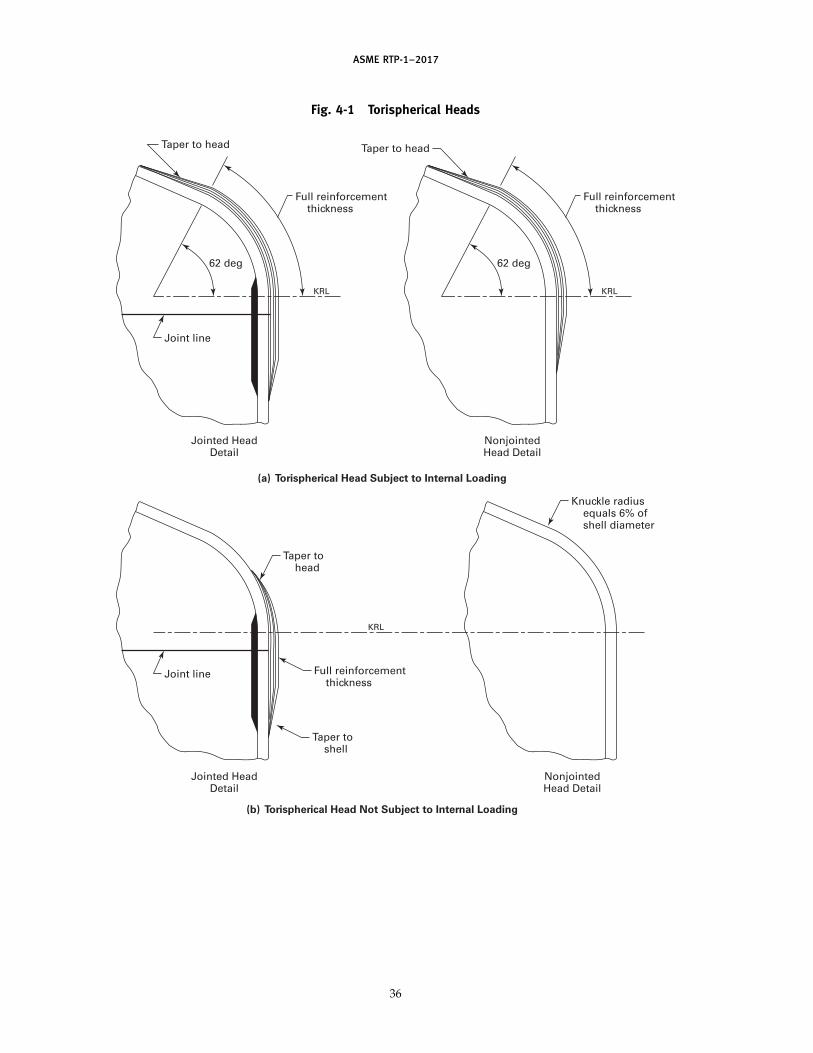
ASME RTP-1–2017
Fig. 4-1 Torispherical Heads
Full reinforcement thickness
Taper to head
NonjointedHead Detail
62 deg
KRL
Full reinforcement thickness
Full reinforcement thickness
Taper to head
Jointed HeadDetail
(a) Torispherical Head Subject to Internal Loading
(b) Torispherical Head Not Subject to Internal Loading
62 deg
Joint line
KRL
NonjointedHead Detail
Taper to head
Taper to shell
Jointed HeadDetail
Joint line
KRL
Knuckle radius equals 6% of shell diameter
36

AS
ME
RTP-1–2017
Fig. 4-2 Flat-Bottom Tank Knuckle Detail
Interior overlay [see para. 4-320 (e)]
Exterior overlay [see para. 4-320 (c) or (d)]
Joint line
t t
t
tb
tb tb
tr
M
L
M
LSF
R
Interior overlay [see para. 4-320 (e)]
Windings with 9,000 psi minimum axial strength
tr
Note (1)
(a) Joined Head to Filament-Wound Shell
tr
Note (1)
(b-1) Integral Head to Filament-Wound Shell (b-2) Integral Head to Filament-Wound Shell
VesselDiameter,
ft
4 ft and underOver 4 ft
R,min.,
in.
L,min.,
in.
111/2
812
M,min.,
in.
34
tb
2M
L
Interior overlay [see para. 4-320 (e)]
tr
R
Note (1)
The greater of tb or (1/2)tr
Exterior overlay[see para. 4-320(d)]
(1/2)tr
R
37 Get more FREE standards from Standard Sharing Group and our chats
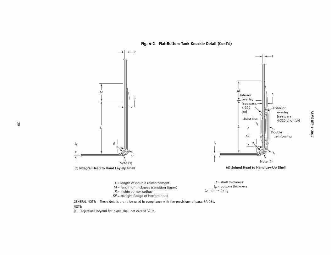
AS
ME
RTP-1–2017
Fig. 4-2 Flat-Bottom Tank Knuckle Detail (Cont’d)
Interior overlay [see para. 4-320 (e)]
Exterior overlay [see para. 4-320(c) or (d)]
Double reinforcing
Joint line
t
tr
tb
tr
M
L
SF
R
Note (1)
(d) Joined Head to Hand Lay-Up Shell
t
tr
tb
tr
M
L
R
Note (1)
(c) Integral Head to Hand Lay-Up Shell
R = inside corner radiusSF = straight flange of bottom head
t = shell thickness tb = bottom thicknesstr (min.) = t + tb
L = length of double reinforcement M = length of thickness transition (taper)
GENERAL NOTE: These details are to be used in compliance with the provisions of para. 3A-261.
NOTE:(1) Projections beyond flat plane shall not exceed 1⁄4 in.
38

ASME RTP-1–2017
Fig. 4-3 Joint Arrangement
First ply of mat
4:1 min. taper
Exterior overlay [see para. 4-320(c) or (d)]
3/8 in. max. gap
3/8 in. max. gap
Resin putty
Resin putty
Maximum offset between upper and lower sections of joint shall be 1/4 in. or 2t /3, whichever is less
t = thickness of thinner part being joined
t = thickness of thinner part being joined
(b) Tolerances for Butt Joints
(a) Tolerances for Bell and Spigot Joints
Bell thickness to be 1/4 in. min. or “t ” in. max.
11/2 in. min. 3 in. max.
4:1 min. taper
4:1 min. taper
Exterior overlay [see para. 4-320(c) or (d)]
Interior overlay [see para. 4-320(e)]
Taper to 1/4 in.
3/8 in. max. gap
Maximum offset 1/4 in. or 2t /3, whichever is less
GENERAL NOTE: The use of putty should be kept to a minimum and used only to fill gaps and offsets, and not be used to fill depressionson the shell. Use of putty may create excessive noise during acoustic emission testing. Taper of the structural portion may be desired tominimize structural discontinuities, such as the case of high axial loading applications.
39
(17)
Get more FREE standards from Standard Sharing Group and our chats

ASME RTP-1–2017
Fig. 4-4 Flush Nozzle Installation
Shell reinforcement Style A
Taper not less than 1:6
d = nozzle diameter dr = cutout reinforcement diameter, in., measured on the vessel surface (greater of 2d or d + 6; see para. 3A-720) hi = inside shear bond length (see Table 4-3)ho = outside shear bond length (see Table 4-3)hs = total shear bond length (see Table 4-3) = hi + ho r = fillet radius (3/8 in. min.) ti = inside installation laminate thickness = tw − to [minimum ti = 0.14 in. (3M, V)] tn = minimum nozzle stub thickness (see Fig. 4-10 and Table 4-2) to = outside installation laminate thickness = tw − ti [minimum to = 0.26 in. (6M)] tr = cutout reinforcement laminate thickness (see para. 3A-730) ts = shell thicknesstw = total installation laminate thickness (minimum tw = 0.40 in.) = greater of tr or 2tn for Style A = lesser of tr or 2tn for Style B tx = reinforcement base thickness = tr /2 (Style B reinforcement)
0.26 min.
Note (1)
hi
ho
ho
totr
to ti
hi
dr
r
d
Shell reinforcement Style B0.26
min.
ho
ho
toto
tr
tx
ts
tn
ti
hi
ti
r
GENERAL NOTE: The installation laminate and the reinforcement may be applied as a single unit.
NOTE:(1) Nozzle wall may also butt up against the shell or head exterior surface.
40

ASME RTP-1–2017
Fig. 4-5 Penetrating Nozzle Installation
Shell reinforcement Style A
Taper not less than 1:6
d = nozzle diameter dr = cutout reinforcement diameter, in., measured on the vessel surface (greater of 2d or d + 6; see para. 3A-720) hi = inside shear bond length (see Table 4-3)ho = outside shear bond length (see Table 4-3)hs = total shear bond length (see Table 4-3) = hi + ho le = penetration length (2 in. min.) r = fillet radius (3/8 in. min.) ti = inside installation laminate thickness = tw − to [minimum ti = 0.14 in. (3M, V)] tn = minimum nozzle stub thickness (see Fig. 4-10 and Table 4-2) to = outside installation laminate thickness = tw − ti [minimum to = 0.26 in. (6M)] tr = cutout reinforcement laminate thickness (see para. 3A-730) ts = shell thicknesstw = total installation laminate thickness (minimum tw = 0.40 in.) = greater of tr or 2tn for Style A = lesser of tr or 2tn for Style B tx = reinforcement base thickness = tr /2 (Style B reinforcement)
0.26 min.
le
ho
ho
tototr
tihi
hi
dr
r
d
Shell reinforcement Style B0.26
min.
ho
ho
toto
tr
tx
tsti
tn
r
GENERAL NOTE: The installation laminate and the reinforcement may be applied as a single unit.
41
Get more FREE standards from Standard Sharing Group and our chats

ASME RTP-1–2017
Fig. 4-6 Bottom Drain Detail
d or 3 in. min.
6:1 taper (typ.)
to
tod
Apply all joint reinforcement before installing nozzle
d
2hi
Plate gusset
Interior overlay [see para. 4-320(e)]
Exterior overlay [see para. 4-320(c) or (d)]
(a) Flush Drain
(b) Full Drain
Interior overlay [see para. 4-320(e)]
6:1 taper (typ.)
Apply all joint reinforcement before installing nozzle
Plate gusset
Exterior overlay [see para. 4-320(c) or (d)]
ti
ti
tr
tr
to
to
trho
ti
ti
hi
hi
trhi
ho
hi2hi
2ho
d or 3 in. min.
2ho
GENERAL NOTE: For flush drain and full drain, notch foundation to accommodate offset. Notch is to be minimized, as determined by aProfessional Engineer. Drawings are to show dimensions of notch. It is optional to fill notch with grout. Grouting requirements are to bedetermined by a Professional Engineer. (See Fig. 4-4 for definitions of nomenclature, such as ho, hi, to, etc.)
42

ASME RTP-1–2017
Fig. 4-7 Stiffener Details for Half-Round, Trapezoidal, and Filament Wound Band Configurations
Ro
R
t and E
R
Taper no steeper than 1:6 (not included in calculations)
A
C
DB
w
Taper no steeper than 1:6 (not included in calculations)
wes = 2BBL + 4R
ts and Es
t and Ets and Es
Taper no steeper than 1:6 (not included in calculations)
wes
wes = 2BBL + w
wes
ts and Es
t and E
(a) Half-Round Configuration
(b) Trapezoidal Configuration
(c) Filament Wound Band Configuration
GENERAL NOTES:(a) See Nonmandatory Appendix NM-17 for the calculation of the BBL and the stiffener effective moment of inertia for the above
configurations.(b) ts p stiffener thickness (in.) and is not limited to alternating layers of mat and woven roving with a final mat layer.
43
Get more FREE standards from Standard Sharing Group and our chats

ASME RTP-1–2017
Fig. 4-8 Support Skirt Attachment Detail
Interior overlay [see para. 4-320(e)]
Apply all joint and knuckle reinforcement before attaching skirt
Tangent line
3 in.
Fill with milled fiber resin putty tol
tsk
Optional 1/4 in. overlay [Note (1)]
tol p thickness of skirt-to-shell overlay bondtsk p thickness of skirt
GENERAL NOTES:(a) tol, length of bond, and type of laminate to be determined by a Professional Engineer [see para. 4-320(g)].(b) Skirt inside diameter shall be the same as vessel inside diameter.
NOTE:(1) If overlay is used, it may be applied after an acoustic emission test.
44
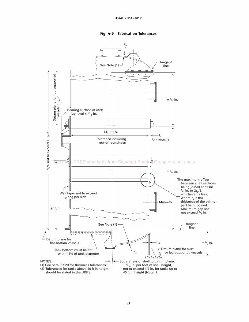
ASME RTP-1–2017
Fig. 4-9 Fabrication Tolerances
th
tb
tsk
ts
Tangent lineSee Note (1)
I.D. ± 1%
Tolerance including out-of-roundness
Manway
Tangent line
The maximum offset between shell sections being joined shall be 1/4 in. or 2ts /3, whichever is less, where ts is the thickness of the thinner part being joined. Maximum gap shall not exceed 3/8 in.
Datum plane for skirt or leg-supported vessels
Squareness of shell to datum plane: ± 1/64 in. per foot of shell height, not to exceed 1/2 in. for tanks up to 40 ft in height [Note (2)]
Datum plane for flat-bottom vessels
See Note (1)
Bearing surface of each lug level ± 1/16 in.
Dat
um
pla
ne
for
lug
-su
pp
ort
ed
ves
sels
± 1
/ 4 in
.
See Note (1)
Wall taper not to exceed 1/2 deg per side
± 1 /
2% n
ot
to e
xcee
d ±
1/ 2
in.
Tank bottom must be flat within 1% of tank diameter
NOTES:(1) See para. 6-920 for thickness tolerances.(2) Tolerances for tanks above 40 ft in height
should be stated in the UBRS.
± 1/4 in.
± 1/4 in.
± 1/2 in.
± 1/2 in.
45
Get more FREE standards from Standard Sharing Group and our chats

ASME RTP-1–2017
Fig. 4-10 Nozzle Flange Dimensions for Class 150 Bolting
FMin. radius 1/4 in.
T
t
hr
A+1/2 in.− 0 in.
C
B
LF
Flange face flatness per Table 4-1. At F, spot face for washers. See below.
ASME B18.21.1C, Min. T, Min. T, Min. Hub Type A Narrow
Size in. Type I Type II Reinforcement, Min. Min. No. Bolt Hole Bolt Washer Size BoltB, A, [Notes Laminates, Laminates, hr, t, L, of Diameter, Diameter, (O.D.), Torque,in. in. (1)–(3)] in. in. in. in. in. Bolts in. in. in. ft-lb
2 6 43⁄4 0.625 0.563 0.25 0.25 25⁄8 4 3⁄45⁄8 15⁄16 25
3 71⁄2 6 0.625 0.563 0.283 0.25 27⁄8 4 3⁄45⁄8 15⁄16 25
4 9 71⁄2 0.813 0.688 0.313 0.25 31⁄4 8 3⁄45⁄8 15⁄16 25
6 11 91⁄2 0.938 0.688 0.313 0.25 313⁄16 8 7⁄83⁄4 11⁄2 25
8 131⁄2 113⁄4 1.125 0.813 0.375 0.25 43⁄8 8 7⁄83⁄4 11⁄2 25
10 16 141⁄4 1.25 0.938 0.5 0.25 43⁄8 12 1 7⁄8 13⁄4 2512 19 17 1.438 1.063 0.625 0.25 415⁄16 12 1 7⁄8 13⁄4 2514 21 183⁄4 1.438 1.063 0.688 0.313 5 12 11⁄8 1 2 30
16 231⁄2 211⁄4 1.563 1.188 0.813 0.313 51⁄16 16 11⁄8 1 2 3018 25 223⁄4 1.625 1.25 0.75 0.375 51⁄2 16 11⁄4 11⁄8 21⁄4 3520 271⁄2 25 1.813 1.313 0.75 0.375 53⁄8 20 11⁄4 11⁄8 21⁄4 3524 32 291⁄2 2.125 1.5 0.813 0.438 53⁄8 20 13⁄8 11⁄4 23⁄8 40
GENERAL NOTES:(a) Gaskets shall be 1⁄8-in. thick full-face elastomeric material having a hardness of Shore A60 ±5.(b) Flange thicknesses are based on 1,800 psi design stress for Type I laminates and a 3,000 psi design stress for Type II laminates. A
design factor of 5:1 was used against ultimate tensile stress in both types of laminate construction.(c) The nozzle neck thicknesses given are based on a Type II or equivalent strength filament wound Type X laminate with a design factor
of 10:1 against ultimate tensile strength and are the minimum thicknesses that may be used in all types of laminate construction. IfType I hand lay-up laminates are utilized, the nozzle neck thicknesses shall be increased for nozzle sizes 10 in. and up.
(d) The rating of all nozzle necks and flanges for all sizes given in this Table is 50 psi.(e) Dimensions generally comparable to Class 150 welding-neck flanges.
NOTES:(1) ±0.06 in. (see ASME B16.5).(2) ±0.03 in. center to center of adjacent bolt holes (see ASME B16.5).(3) Eccentricity between bolt holes and center of nozzle: for size 2 in., ±0.03 in.; for size 3 in. and larger, ±0.06 in.
46

ASME RTP-1–2017
Fig. 4-11 Flanged Nozzle Lay-Up Method
Three full-face plies of mat plus one ply surface matT/2
[Note (1)]
Flange
(a) Flange on Pipe Type
CL
1/4 in. radius (min.)
L
T
t
T/2[Note (1)]
NOTE:(1) T/2 equals hub reinforcement.
Flange
(b) Integral Type
CL
1/4 in. radius (min.)
L
T
t
47
Get more FREE standards from Standard Sharing Group and our chats
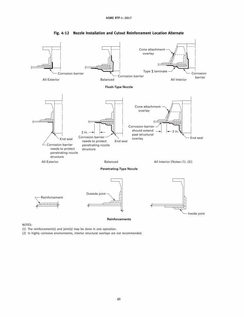
ASME RTP-1–2017
Fig. 4-12 Nozzle Installation and Cutout Reinforcement Location Alternate
Corrosion barrier
All ExteriorCorrosion barrier
Balanced
Flush-Type Nozzle
Penetrating-Type Nozzle
Reinforcements
Balanced
Outside joint
All Exterior
Reinforcement
Corrosion barrier
All Interior
Type T laminate
Cone attachment overlay
End seal
2 in.
All Interior [Notes (1), (2)]
Corrosion barrier should extend past structural overlayCorrosion barrier
needs to protect penetrating nozzle structure
Corrosion barrier needs to protect penetrating nozzle structure
Cone attachment overlay
End seal
Inside joint
2 in.
End seal
T
NOTES:(1) The reinforcement(s) and joint(s) may be done in one operation.(2) In highly corrosive environments, interior structural overlays are not recommended.
48
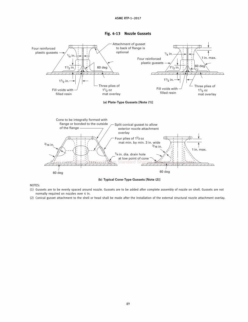
ASME RTP-1–2017
Fig. 4-13 Nozzle Gussets
Attachment of gusset to back of flange is optional
Fill voids with filled resin
1/4 in. dia. drain hole at low point of cone
Four plies of 11/2 oz mat min. by min. 3 in. wide
Split conical gusset to allow exterior nozzle attachment overlay
Cone to be integrally formed with flange or bonded to the outside of the flange
60 deg
Four reinforced plastic gussets
Three plies of 11/2 oz mat overlay
(a) Plate-Type Gussets [Note (1)]
(b) Typical Cone-Type Gussets [Note (2)]
11/2 in.
11/2 in.
1/4 in.
Fill voids with filled resin
60 deg
60 deg
Four reinforced plastic gussets
Three plies of 11/2 oz mat overlay
11/2 in.
1 in. max.
11/2 in.
1/4 in.
1 in. max.3/16 in.
60 deg
3/16 in.
NOTES:(1) Gussets are to be evenly spaced around nozzle. Gussets are to be added after complete assembly of nozzle on shell. Gussets are not
normally required on nozzles over 4 in.(2) Conical gusset attachment to the shell or head shall be made after the installation of the external structural nozzle attachment overlay.
49
Get more FREE standards from Standard Sharing Group and our chats

ASME RTP-1–2017
Fig. 4-14 Flange Tolerances
Reverse Drawback
(b)
Flange Drawback
(c)
Flange waviness(a)
See Table 4-1
50
Fig. 4-15 Flat Cored Bottom Knuckle Detail
R
Grain direction
45 deg
GENERAL NOTE: Refer to Fig. 4-2 for flat-bottom tank corner detail.

ASME RTP-1–2017
Table 4-1 Flange Flatness Tolerance
Flange Size, in. Tolerance, in.
2–84 +1⁄32
90–108 +1⁄16
114–144 +3⁄32
Table 4-2 Typical Dimensions of Manways
Minimum MinimumDiameter of Thickness of Min. Manway Diameter of Number Bolt Hole
Minimum Flange and Cover, Flange and Wall Bolt Circle, in. of Diameter,Size, in. in. Cover, in. Thickness, in. [Notes (1)–(3)] Bolts in.
Pressurized manway — up to 15 psig
20 271⁄2 1 3⁄8 25 20 3⁄422 30 1 3⁄8 27 20 3⁄424 32 11⁄4
3⁄8 291⁄2 20 3⁄4
Manway — atmospheric pressure, up to 0.5 psig
20 271⁄23⁄8
1⁄4 25 20 1⁄222 30 3⁄8
1⁄4 27 20 1⁄224 32 3⁄8
1⁄4 291⁄2 20 1⁄2
GENERAL NOTES:(a) Bolt size equals bolt hole diameter minus 1⁄8 in. (3 mm).(b) Gaskets shall be 1⁄8 in. thick full-face elastomeric material having a hardness of Shore A60 ±5.
NOTES:(1) ±0.06 in. (ASME B16.5).(2) ±0.03 in. center to center of adjacent bolt holes (ASME B16.5).(3) ±0.06 in. eccentricity between bolt circle and center of nozzle.
Table 4-3 Shear Bond Length
Minimum Nominal Overlay Minimum Shear Length,Thickness, in. hs, in. [Note (1)]
1⁄4 35⁄16 33⁄8 3
7⁄16 31⁄21⁄2 4
9⁄16 41⁄25⁄8 5
11⁄16 51⁄23⁄4 67⁄8 71 8
GENERAL NOTE: When internal overlay serves only as a corrosionbarrier, the total shear length shall be placed on the exterior overlay.
NOTE:(1) hs is total shear length (ho + hi). See Figs. 4-4 and 4-5.
51
Get more FREE standards from Standard Sharing Group and our chats

ASME RTP-1–2017
Part 5Overpressure Protection
5-100 BASIS FOR DESIGN
5-110 Atmospheric Tanks
(a) Atmospheric tanks shall be directly vented toatmosphere through an open top or through a minimumheight, permanently attached vent.
(b) Vents for atmospheric tanks shall have a cross-sectional area equal to or exceeding the combined areasof inlets or outlets, whichever is greater.
(c) Atmospheric tanks may not be equipped with aflanged vent or a removable vent.
(d) All atmospheric tanks shall be equipped with anoverflow at or below the top of the shell and the overflowmust have a cross-sectional area equal to or exceedingthe combined areas of inlets.
5-120 Excessive Pressure
In view of the relatively low mechanical propertiesof RTP compared with metals, careful considerationmust be given to excessive internal or external pressure.
5-130 Operating Characteristics
Operating conditions shall reflect both normal andabnormal operations relating to internal or external pres-sure, venting, vessel overflow location, and processupsets.
5-200 PROTECTION AGAINST OVERPRESSURE
All vessels within the scope of this Standard shall beprovided with protection against internal and/or exter-nal pressure exceeding maximum allowable pressures.This shall be the responsibility of the User.
The size and location of all nozzles used for overpres-sure protection set forth in para. 5-300 shall be shownin the equipment sketch and nozzle schedule attachedto the UBRS.
5-300 TYPE OF OVERPRESSURE PROTECTION
Protection against overpressure shall be accomplishedby one or a combination of the following devices:
(a) direct spring-loaded safety or safety relief valves(b) rupture disks(c) deadweight loaded pallet-type vent valves(d) free vents
52
5-400 LOCATION OF OVERPRESSURE PROTECTIONDEVICES
Devices listed in paras. 5-300(a) through (d) shall belocated in the top of the vessel above the maximumliquid level.
Overflows for vertical vessels shall be on or belowthe top head tangent line. Overflows for horizontal ves-sels shall be located in the head or shell below the topof the shell.
The User shall not use free vents as liquid overflows.
5-500 INSTALLATION PRACTICES
Unsecured (not locked or sealed open) block valvesshall not be installed between the vessel and any reliev-ing device.
5-600 OVERPRESSURE DEVICE SET PRESSURE
Relief devices shall be set no higher than the maxi-mum allowable working pressure.
5-700 RELIEF DEVICE SIZING
5-710 Sizing of Spring or Deadweight Loaded Valvesand Rupture Disks
Devices listed in paras. 5-300(a), (b), and (c) shall besized in accordance with the device manufacturer’s cata-log so that at its full flow capacity the relief pressureshall not exceed 110% of the vessel MAWP.
5-720 Sizing of Vents and Overflows
Vents and overflows that discharge freely into theatmosphere shall be sized sufficiently to handle the flowdisplacement of all combined inlet and outlet nozzleswithout creating any pressure above the vessel’s MAWPor any external pressure higher than the vessel’sMAEWP.
5-800 DISCHARGE LINES FROM PRESSURE RELIEFDEVICES
Discharge lines from pressure relief devices shall bedesigned to facilitate drainage or shall be fitted with an

ASME RTP-1–2017
open drain to prevent lodging in the discharge side ofthe safety device. Discharge lines shall lead to a safeplace of discharge. The size of the discharge lines shallbe such that any pressure that may exist or develop willnot reduce the relieving capacity of the relieving devicebelow that required to protect the vessel properly.
5-900 RESPONSIBILITY FOR DESIGN ANDSELECTION
The design and/or selection of pressure relief devices,the sizing of mounting nozzle, and the size, length, androuting of discharge piping shall be the responsibilityof the User and not that of the Fabricator or the Inspector.
53
Get more FREE standards from Standard Sharing Group and our chats
ASME RTP-1–2017
Part 6Inspection and Tests
6-100 SCOPE
This Part covers inspection and testing of RTP corro-sion resistant vessels. It is intended to ensure that avessel has been designed and fabricated in accordancewith the requirements of the latest revision of the design,the approved drawings, and this Standard.
This Part does not cover specifications, instructions,and inspections referred to in the User ’s BasicRequirements Specification (UBRS), which may be morerestrictive than the requirements of this Standard andmay require additional verification by the User’s inspec-tor. Nonmandatory Appendix NM-7 covers User ’sinspection.
6-200 INSPECTOR
See para. 1-400.
6-300 INSPECTION AND RESPONSIBILITY
(a) The Fabricator of a vessel has the responsibilityto comply with all the requirements of this Standard,the design, and the UBRS. The Fabricator is additionallyresponsible for assuring that any RTP subassembliesor components fabricated by a Subcontractor that willbecome a portion of the vessel and are part of the scopeof RTP-1 (see paras. 1-110 and 1-120) shall be fabricatedby an ASME RTP-1 certified shop and are to be in fullcompliance with all the requirements of RTP-1. PartialData Reports shall accompany any such subassemblyor component and shall be signed by the Subcontractor’sCertified Individual.
(b) Any subcontracted or outsourced subassembly orcomponent to be furnished with a vessel by a Fabricatorthat will become a portion of the vessel, or a load-bearingaccessory that will be attached to the vessel (i.e., a sup-port), shall also be inspected by the Fabricator’s inspec-tor. Procedures and general requirements for acceptanceor rejection shall be part of the Fabricator’s QualityControl Program.
(c) The Fabricator shall have a written Quality ControlManual, to include defined procedures and forms so asto control the process of fabrication. The Fabricator’sQuality Control Program shall be supervised by theFabricator and shall be in effective operation throughoutthe process of fabrication. See MandatoryAppendix M-4.
54
(d) A copy of the Fabricator’s Quality Control Manualshall be made available to the Inspector on request. TheFabricator’s Quality Control Manual may contain pro-prietary information and procedures. No copies of theFabricator’s Quality Control Manual shall be removedfrom the Fabricator’s premises without the Fabricator’spermission. This security protection, however, is not toapply to quality control forms and checklists which maybe a portion of the Quality Control Manual but are neces-sary to be used during fabrication to check and controlthe fabrication process.
(e) The Certified Individual’s responsibility is to ver-ify that the Fabricator’s Quality Control Program is ineffective operation via an annual audit as required inpara. 1-410(a) and to additionally make such specificinspections and tests as are required by this Standard.The Inspector shall provide a complete report includingall data as required in paras. 6-910 through 6-960.
(f) Prior to the start of fabrication, the Fabricator shallmake available to the Inspector such records pertainingto the vessel as required to permit the Inspector to per-form the inspections. These shall include drawings,material test results, the UBRS, the Fabricator’s DesignReport, and any other reports or records as required.The Fabricator shall provide for Inspector’s hold pointsand verifications of satisfactory completion. Fabricationshall not proceed beyond a hold point until specifiedinspections have been made.
(g) The Fabricator shall make his/her quality controlpersonnel available to the Inspector.
(h) The Fabricator shall make available to theInspector any and all necessary tools and test equipmentso the Inspector may conduct all inspections requiredby this Standard.
(i) Final acceptance of the vessel by the CertifiedIndividual shall be obtained by the Fabricator prior tothe application of the official ASME Certification Markwith RTP Designator. The Certified Individual shall signthe Fabricator ’s Certificate of Compliance on theFabricator ’s Data Report only when the CertifiedIndividual is satisfied that all requirements of thisStandard have been met [see paras. 6-900(d) and (e)].
6-400 CONDITIONS FOR INSPECTION
(a) The Fabricator shall ensure that the vessel is cleanand free of foreign materials to permit the Inspector toinspect all accessible surfaces.

ASME RTP-1–2017
(b) The Fabricator shall position and ensure that thevessel is in suitable condition to permit reasonable andsafe access for inspection.
(c) The Fabricator shall provide reasonable and safemeans, such as ladders and/or platforms, to permit theInspector to safely inspect accessible inner and outersurfaces of the vessel.
(d) The User’s inspector should be familiar with thepossible hazards and safety requirements associatedwith the use of all RTP materials and fabrication meth-ods. The User’s inspector should observe safety require-ments set up by the Fabricator and should be alert tofabricating shop hazards that might be associated withhydrostatic testing of equipment.
6-500 EQUIPMENT DESIGN
The Inspector shall examine the Fabricator’s designrecords and reports and verify that the vessel conformsto the latest revision of approved drawings and theUBRS, and that the Fabricator’s Design Report has beencertified by a registered Professional Engineer.
6-600 MATERIALS
The Inspector shall verify that materials used in fabri-cation of a vessel comply with the requirements of thisStandard and the UBRS.
6-700 FABRICATION
The Inspector shall establish hold points and makeperiodic inspections and measurements of the vessel asare required by this Standard to verify that fabricationis in accordance with the requirements of this Standardand the UBRS.
At the completion of each hold point inspection, theInspector shall report results on forms provided in theFabricator’s Quality Control Program, and highlight anydiscrepancies requiring corrective action.
6-800 FABRICATOR’S QUALITY ASSURANCEPROGRAM
The Inspector shall make such checks as are necessaryto verify that the Fabricator ’s Quality AssuranceProgram is in effective operation. In addition, theCertified Individual shall perform an annual audit ofthe Fabricator’s Quality Assurance Program.
Any discrepancies shall be promptly brought to theFabricator’s attention for discussion and resolution.
6-900 FINAL INSPECTION
(a) At the time of final inspection, the Fabricator shallprovide to the Inspector the final revision of all of thefollowing documents:
(1) design drawings
55
(2) UBRS(3) completed and signed copies of all forms from
the Fabricator’s Quality Control Manual that were usedduring fabrication to check and verify compliance withthis Standard and the design
(4) any copies of Fabricator’s Partial Data Reports,with signed Certificates of Compliance, applicable tothe finished fabrication (see Table 1-3)
(5) copies of all inspection reports made by anyinspector/Inspector during the course of fabrication
(6) completed original document of the Fabricator’sData Report, applicable to the vessel to be inspected,with the Certificate of Compliance signed and datedby the authorized representative of the Fabricator (seeTable 1-2)
(7) copy of the final revision of the Fabricator’sDesign Report
(8) the nameplate that is to be applied to the vessel,so that the Inspector may verify that the nameplatemeets the requirements of the UBRS and para. 1-540
(b) Design drawings shall show design thicknessesand the laminate reinforcing sequence for every sectionor member. If, during the course of fabrication, it wasnecessary to add repeatable units to the laminate [seepara. 6-920(f)(4)], this change shall be noted and high-lighted on the drawings provided to the Inspector.
(c) The Fabricator shall also make available to theInspector all nozzle and manway cutouts, each identifiedclearly as to its point of origin on the vessel.
(d) Upon completion of final inspection, the Inspectorshall prepare a brief report summarizing his/her inspec-tion activities and findings, and submit the report tothe Fabricator as an attachment to the Certificate ofCompliance.
(e) When the Inspector has completed the inspectionsand found the results to be within required tolerances,the Inspector shall present his/her inspection reportalong with any findings to the Certified Individual. TheCertified Individual shall sign and date the Certificateof Compliance prior to returning it to the Fabricatorwith the inspection report.
(f) Paragraphs 6-910 through 6-960 describe the mini-mum basic tests that shall be made, witnessed, or veri-fied by the Inspector prior to or at the time of finalinspection.
6-910 Resin Cure
(a) During the course of fabrication, the Fabricatorshall make all such checks necessary to ensure that resinadditives, promotion, catalyzation, dilution, and curingare controlled and are within the requirements of thisStandard. The Fabricator’s Quality Control Programshall include procedures and forms, to be used through-out fabrication, to control the ongoing process of resinhandling and curing so as to ensure that cure is withinrequired tolerance prior to the final inspection.
Get more FREE standards from Standard Sharing Group and our chats
ASME RTP-1–2017
(b) The Inspector shall verify that the resin has prop-erly cured by testing the internal (process exposed) sur-faces of major equipment components and joints, suchas heads, shell sections, head/shell and shell/shell junc-ture overlays, nozzle and manway necks 18 in. diameterand larger, and manway covers and blind flanges.
Additionally, the following external surfaces shall betested to verify proper resin cure: head/shell and shell/shell juncture overlays, and nozzle and manway junctureoverlays. Testing shall be as follows:
(1) Surface hardness shall be determined in accor-dance with ASTM D2583, except D2583 paras. 6.1, 8.1,8.2, and 10.1. Allowable surface temperature range shallbe 50°F to 90°F. Readings shall not be taken on pits,heavy mold release, or other irregularities that may affectthe readings. Only dense resin-rich surfaces shall betested. The Barcol reading will be the average of fiveimpressions taken at various points broadly distributedabout the component or joint so as to provide a represen-tative hardness.
(2) If low Barcol readings are encountered on waxtop-coated surfaces, retest after removing the wax bylight sanding or scraping.
(3) Barcol test data shall verify that the surfacehardness of laminates with glass surfacing veil or carbonsurfacing veil has reached at least 90% of the hardnessspecified by the resin manufacturer for a clear resincasting.
(4) Laminates with organic surfacing veil may havea Barcol reading lower than 90% of the hardness asspecified by the resin manufacturer for a clear resincasting. The minimum acceptable Barcol reading shallbe established between the User and Fabricator prior tofabrication.
(5) Barcol instruments shall be calibrated prior toand during use using the test discs and procedure recom-mended by the manufacturer of the Barcol instrument.
(6) The Inspector shall confirm that minimumBarcol hardness values have been established, the testvalues are within acceptable limits, and the Barcol instru-ment has been calibrated.
(7) The Inspector shall verify that all potential air-inhibited interior surfaces and overlays, and other sur-faces selected at the Inspector’s option, shall pass anacetone sensitivity test. For this test, a few drops ofacetone are applied to a 1-in.2 to 2-in.2 area, which isrubbed slightly until the acetone has evaporated. Tacki-ness or softness indicates unacceptable cure of the sur-face resin.
(c) Failure to meet the requirements of these tests shallbe considered a nonconformance and corrections shallbe made by the Fabricator in accordance withMandatory Appendix M-7.
(d) The Inspector shall include results and Barcol datafrom the above tests in the inspection report.
56
6-920 Dimensions and Laminate Thickness Checks
(a) During the course of fabrication, the Fabricatorshall make checks to ensure that dimensions and lami-nate thicknesses are within the requirements of thisStandard and the design. The Fabricator ’s QualityControl Program shall include procedures and forms, tobe used throughout fabrication, to control the ongoingprocess of checking all dimensions and laminate thick-nesses (to ensure that they are within required toler-ances) prior to the final inspection.
(b) Refer to Fig. 4-9 for mandatory dimensional toler-ances. The Inspector shall verify that all these dimen-sions are within tolerances.
(c) Refer to Figs. 4-1 through 4-5, Fig. 4-7, andFigs. 4-10 through 4-13 for details and tolerances onoverlay, flange, nozzle, and manway designs. TheInspector shall select and check several of these details.
(d) Overlays at head-to-shell and shell-to-shell jointsand at manways shall be closely inspected and shallconform to the requirements of Part 4.
(e) The Inspector shall select and check several lami-nate thicknesses critical to the safe performance of theequipment. Approved methods of measurement are out-lined in para. 2A-400(e).
(f) Laminate Thickness and Tolerances(1) The nature of existing practical RTP fabrication
methods leads to nonparallel and somewhat irregularsurfaces of a laminate. Consequently, a single thicknessmeasurement at one point is not sufficient to characterizea laminate thickness at that area of a laminate. Addition-ally, the thickness measurement of one small area oflaminate on a part of the equipment (such as a shellor head) is not sufficient to characterize the laminatethickness of that part. For purposes of characterizingthe thickness of laminates, this shall be referred to aslaminate thickness variation.
(2) The following procedures shall be used to deter-mine thickness:
(-a) Determining Average Spot Thickness of OneSmall Area or of a Small Component (Such as a 10-in. Flange).Lightly mark a continuous circle between 4 in. and 12 in.diameter on the component/area to be thicknesschecked (on a small component/area that will notaccommodate a 4 in. diameter circle, mark the circle aslarge as the small component/area will allow). Selectsix points to be measured for thickness so that all pointsare well distributed (not in a line) over the area of thecircle. (A hole may occupy a portion of the area of thecircle marked, such as on a flange face or at a point wherea nozzle will penetrate a vessel wall.) Avoid selection ofa spot to be measured that straddles an overlaid joint.
Average the six readings taken; this is the average spotthickness of the small area or small component. Recordall six measurements in the inspection report.
(-b) Determining the Average Thickness of a MajorPart of a Piece of Equipment [Such as a Head, Shell, Nozzle (or

(17)
ASME RTP-1–2017
Subassembly), or Manway Wall; Body or Manway Flange].Four average spot thickness measurements shall betaken, located at the discretion of the Inspector, so as tobe broadly distributed over a representative area of thepart. The Inspector shall locate one area to be measuredat what appears to be the thinnest portion of the partand a second area at what appears to be the thickestportion of the part. Avoid selection of spots falling overjoints (overlays).
The other two areas shall be located so as to achievea representative distribution over the area of the part.
Average the four average spot thicknesses; this is theaverage thickness of the major part. Record all measurementdata in the inspection report.
(-c) Special Measurement Practices. Cylindricalshells designed with tapered walls or stepped thicknesswalls require treatment as a multiplicity of parts, whereeach part to be measured shall represent a wall thicknesszone as designated in the design.
The measurement of nozzle or manway cutouts, eachto represent one average spot thickness, is a convenientmeans to arrive at the average thickness of a vessel heador shell.
(3) Refer to Subpart 2C for permissible toleranceson laminate thickness variation.
(4) Variations in thickness may be caused by factorssuch as resin viscosity, mat or chop density, wetout,fabrication technique, etc. Refer to MandatoryAppendix M-7, para. M7-640, for requirements and pro-cedures to compensate for these variations.
(g) The Inspector shall include results of dimensionaland laminate thickness tests in the inspection report.
(h) Balsa Wood Core Laminates. Balsa wood core lami-nates shall be subject to the same average spot thicknessrules as outlined in (f). Average thickness records shallbe taken on the interior and exterior laminate in accor-dance with (f).
6-930 Physical Property and Laminate ReinforcingContent Tests
(a) The Fabricator is responsible for producing lami-nates that will meet or exceed permissible mechanicalproperty values as used in the design and as are estab-lished as minimum within Subparts 2A and/or 2B. Lam-inates shall also be in accordance with the reinforcingsequence and minimum reinforcing content as estab-lished in Subparts 2A and/or 2B.
(b) During the course of fabrication, the Fabricatorshall ensure that laminate reinforcing and mechanicalproperties are controlled and are within the require-ments of this Standard and the design. The Fabricator’sQuality Control Program shall include procedures andforms, to be used throughout fabrication, to control theongoing process of checking laminate reinforcing andmechanical properties, and to ensure that they are withinrequired tolerances prior to the final inspection.
57
All such ongoing checks and/or tests done to ensurequality control, but not including Proof Tests asdescribed in (d), may be done by either the Fabricatoror an independent testing laboratory and require certifi-cation only by the individual who conducted or super-vised the testing.
(c) The Inspector shall visually inspect all nozzle andmanway cutouts. At least one such cutout from eachmajor component (or fabricated section if a componentis fabricated in more than one section) that has a cutoutshall be used to verify the reinforcing sequence in accor-dance with the design drawings. The Inspector shallnote the results in the inspection report. With certainlaminate reinforcing designs and some resins, it maynot be possible to verify reinforcing sequence throughvisual inspection. In such cases, the Inspector shallrequire the Fabricator to conduct sufficient laminateburnout tests, in accordance with ASTM D2584, usingsamples taken from the cutouts, to verify reinforcingsequence through count after the burnout test. For eachsuch test made, the reinforcing content weight percentshall also be determined and recorded in the inspectionreport.
(d) Laminate Proof Tests are mandatory for all vesselsbuilt to this Standard having a MAWP or MAEWP equalto or exceeding 2 psig. Additionally, Laminate ProofTests are required on all vessels that are field fabricatedand all vessels with an inside diameter equal to orgreater than 16 ft.
(1) Fabricators shall verify through Proof Tests thatthe laminate mechanical property data, the reinforcingsequence, and reinforcing content weight percent dataof the as-constructed head or cylindrical shell are inaccordance with
(-a) the requirements of Subparts 2A and/or 2B(-b) all tensile strength and tensile modulus val-
ues employed in the design calculations (Proof Test val-ues shall meet or exceed design values)
(-c) the laminate sequence as specified in thedesign drawings
(2) Proof Tests may be performed by an indepen-dent testing laboratory (contracted by the Fabricator) orby the Fabricator, provided proper test equipment isavailable. The test results shall be accepted providingthe laboratory maintains either ISO Certification thatincludes internal self audits and third party audits orthe laboratory is accredited to conduct the test by theAmerican Association for Laboratory Accreditation. Ifthe laboratory conducting the testing services is notaccredited or certified to conduct the tests, then the test-ing procedures shall be reviewed and witnessed. Theowner shall specify acceptable parties to review the writ-ten procedures and witness the testing. In either case, thetest results shall be reviewed by a registered ProfessionalEngineer to determine if they meet the designrequirements.
Get more FREE standards from Standard Sharing Group and our chats
ASME RTP-1–2017
(3) For vessel shells constructed of laminates essen-tially isotropic in the hoop and axial directions (e.g.,Type I or Type II laminates), at least one set of mechanicalproperty tests (ASTM D638, ASTM D3039, orASTM D5083) and one reinforcing content weight per-cent test (ASTM D2584) shall be carried out using lami-nate samples taken from nozzle, shell end trim, ormanway cutouts. Data obtained from the tests shall bethe tensile strength and tensile modulus of elasticity, thereinforcing content weight percent, and the reinforcingsequence.
(4) For cylindrical shells constructed of anisotropiclaminates (e.g., filament wound laminates), the follow-ing mechanical property tests are required: flexuralstrength and modulus in the hoop and axial directions(corrosion barrier in compression; ASTM D790), andtensile strength and modulus in the axial direction(ASTM D638). The reinforcing content weight percent(ASTM D2584) and the reinforcing sequence shall alsobe determined.
(5) Specimen requirements shall be as follows:(-a) Test specimens shall not be machined on the
inner or outer surface.(-b) Specimens prepared from cylinder cutouts
for isotropic laminates as defined above shall be cut inthe axial direction of the cylinder to minimize surfacecurvature.
(-c) Specimens prepared from flat laminates con-taining woven roving shall have their long axis parallelto the warp of the woven roving.
(-d) When the design requires that all or a portionof the corrosion barrier is to be excluded as a contributorto the structural strength of a laminate, then tests oflaminates as fabricated would not yield correct data. Insuch cases, that portion to be excluded as a contributor tostructural strength shall be removed from test specimensprior to testing. By so doing, tensile strength and tensilemodulus test data produced may be compared with theactual structural design values used and the thicknessesof structural portions of laminates that were specifiedin the design.
This may be conveniently accomplished by placing apiece of release film on (or within) the corrosion barrierduring lamination of the shell, at manway cutout loca-tion, or on an extended length of shell near the man-drel end.
CAUTION: Mark the release film location prominently! A fail-ure to completely remove material covering release film couldcause delamination during service.
Test samples shall then be prepared from materialtaken from the release film location.
(e) The Inspector shall include copies of all mechani-cal property and reinforcing content Proof Test reportsin the inspection report.
58
6-940 Laminate Imperfections — Visual Inspection
(a) During the course of fabrication, the Fabricatorshall make all such checks necessary to ensure that lami-nate imperfections (as defined in Table 6-1) are withinthe requirements of this Standard and the VisualInspection Acceptance Level as specified in the UBRS.The Fabricator’s Quality Control Program shall includeprocedures and forms to be used to control the ongoingprocess of laminate fabrication so as to ensure thatimperfections are within required tolerances prior to thefinal inspection.
(b) Prior to making a visual examination, theInspector shall review the UBRS to determine whichVisual Inspection Acceptance Level has been specified.
(c) The Inspector shall visually check interior andexterior surfaces. (Inspection may be made with the aidof a light placed behind the section to detect air voids,delamination, lack of fiber wetting, and other imperfec-tions as described in Table 6-1.)
(d) Visual inspection shall be made before an exteriorpigmented coating or insulation is applied to the shellor heads of a vessel. Where exterior pigmentation orinsulation has been specified, the Fabricator, User, andInspector must discuss and agree on visual inspectionmethods and arrange for closely timed and scheduledinspections.
(e) The Inspector shall record the results of the visualinspection in the inspection report.
(f) Balsa Wood Core Laminates(1) Visual inspection of the component shall be
required from the interior side of the laminate to checkfor delamination of the balsa wood core.
(2) Laminates that are to have a balsa wood coreapplied over them after resin saturation and prior tocuring shall be visually inspected prior to applying thebalsa wood core.
(3) The Fabricator shall take the appropriate mea-sures to ensure adhesion of the interior laminate to thebalsa wood core.
6-950 Pressure Tests and Acoustic Emission Tests
(a) A water fill hydrostatic test shall be performed onall vessels with MAWP above 0.5 psig. The test pressureat the top of the vessel shall be 110% to 120% of thedesign pressure.
(b) A vessel with MAWP at or below 0.5 psig shallbe filled with water to at least its full designated liquidcapacity, regardless of the specific gravity of the materialto be contained.
(c) Vessels with an inside diameter less than or equalto 16 ft and with MAEWP less than or equal to 6 in. ofwater, and vessels larger than 16-ft inside diameter withMAEWP less than or equal to 1 in. of water, are exemptfrom vacuum testing. All other vessels designed for vac-uum service shall be evacuated to the MAEWP.
(17)

AS
ME
RTP-1–2017
(17) Table 6-1 RTP Visual Inspection Acceptance Criteria
Maximum Size and Cumulative Sum of Imperfections Allowable[After Repair. See General Notes (a) and (b). Imperfections Subject to Cumulative Sum
Limitation are Highlighted With an Asterisk.]
Definition of Visual Inspection Levels (to be Interior LayerSpecified by User or User’s Agent): (~0.125 in. Thick) Structural Layer
Level ➀ p Critically Corrosion Resistant Inner Surface Mat or Chopped Balance of Laminate (IncludingLevel ➁ p Standard Corrosion Resistant Veil(s), Surfacing Mat Strand Spray Layers Outer Surface)
ImperfectionName Definition of Imperfection Level ➀ Level ➁ Level ➀ Level ➁ Level ➀ Level ➁ Notes
Burned areas Showing evidence of thermal None None None None None Never in more Discoloration only,decomposition through than one never delaminationdiscoloration or heavy dis- ply and not or decompositiontortion to exceed
16 in.2 inany vessel
Chips (surface) Small pieces broken off an *1⁄8 in. diam- *1⁄8 in. diam- . . . . . . *1⁄4 in. diame- *1⁄2 in. diame- . . .edge or surface eter max. eter max. ter or 1⁄2 in. ter or 1 in.
by 30% of by 50% of length max. length max.veil(s) veil(s) by 1⁄16 in. by 1⁄16 in.thickness thickness deep deepmax. max.
Cracks Actual ruptures or debond of None None None None None None Not to include areasportions of the structure to be covered by
joints
Crazing Fine cracks at the surface of None None . . . . . . Max. 1 in. Max. 2 in. . . .(surface) a laminate long by long by
1⁄64 in. 1⁄64 in.deep, max. deep, max.density 3 in density 5 inany square any squarefoot foot
Delamination Separation of the layers in a None None None None None *None in . . .(internal) laminate three plies
adjacent tointeriorlayer, nonelarger than1 in.2 totalarea
59 Get more FREE standards from Standard Sharing Group and our chats

AS
ME
RTP-1–2017
Table 6-1 RTP Visual Inspection Acceptance Criteria (Cont’d)
Maximum Size and Cumulative Sum of Imperfections Allowable[After Repair. See General Notes (a) and (b). Imperfections Subject to Cumulative Sum Limitation are
Highlighted With an Asterisk.]
Definition of Visual Inspection Levels (to be Interior LayerSpecified by User or User’s Agent): (~0.125 in. Thick) Structural Layer
Level ➀ p Critically Corrosion Resistant Inner Surface Mat or Chopped Balance of Laminate (Including OuterLevel ➁ p Standard Corrosion Resistant Veil(s), Surfacing Mat Strand Spray Layers Surface)
ImperfectionName Definition of Imperfection Level ➀ Level ➁ Level ➀ Level ➁ Level ➀ Level ➁ Notes
Dry spot Area of surface where the None None . . . . . . None None . . .(surface) reinforcement has not
been wetted with resin
Edge exposure Exposure of multiple layers None None . . . . . . None None Edges exposedof the reinforcing matrix to contentsto the vessel contents, shall be cov-usually as a result of ered withshaping or cutting a sec- same num-tion to be secondary ber of veilsbonded (interior of vessel as inneronly) surface
Foreign Particles included in a lami- *3⁄16 in. long *1⁄4 in. long *1⁄2 in. long *1⁄2 in. long *Dime size, *Nickel size, Shall be fullyinclusion nate that are foreign to its max. by max. by max. by max. by never to pene- never to pene- resin wetted
composition (not a minute dia. or dia. or dia. or dia. or trate lamina- trate lamina- and encap-speck of dust) thickness thickness thickness thickness tion to tion to sulated
not more not more not more not more lamination laminationthan 30% than 50% than 30% than 50%of veil(s) of veil(s) of interior of interiorthickness thickness layer layer
thickness thickness
Gaseous Air entrapment within, on, Max. diame- Max. diame- Max. diame- Max. diame- Max. diameter Max. diameter Shall not bebubbles or or between plies of ter 1⁄16 in. ter 1⁄16 in. ter 1⁄8 in. ter 1⁄8 in. 3⁄16 in. 1⁄4 in. breakableblisters reinforcement, 0.015 in. by 30% by 50% with a sharp
diameter and larger of veil(s) of veil(s) pointthickness thicknessdeep deep
←⎯⎯⎯⎯⎯⎯ Refer to User’s Specification for quantity limitations ⎯⎯⎯⎯⎯⎯→
Pimples Small, sharp, conical eleva- *Max. height *Max. height . . . . . . ←⎯⎯⎯⎯ No limit ⎯⎯⎯⎯→ Shall be fully(surface) tions on the surface of a or diame- or diame- resin filled
laminate ter 1⁄64 in. ter 1⁄32 in. and wetted;generally,capturedsanding dust
60

AS
ME
RTP-1–2017
Table 6-1 RTP Visual Inspection Acceptance Criteria (Cont’d)
Maximum Size and Cumulative Sum of Imperfections Allowable[After Repair. See General Notes (a) and (b). Imperfections Subject to Cumulative Sum Limitation
are Highlighted With an Asterisk.]
Definition of Visual Inspection Levels (to be Interior LayerSpecified by User or User’s Agent): (~0.125 in. Thick) Structural Layer
Level ➀ p Critically Corrosion Resistant Inner Surface Mat or Chopped Balance of Laminate (IncludingLevel ➁ p Standard Corrosion Resistant Veil(s), Surfacing Mat Strand Spray Layers Outer Surface)
ImperfectionName Definition of Imperfection Level ➀ Level ➁ Level ➀ Level ➁ Level ➀ Level ➁ Notes
Pit (surface) Small crater in the surface *1⁄8 in. diam- *1⁄8 in. diam- . . . . . . *1⁄4 in. diame- *1⁄4 in. diame- No fibers mayof a laminate eter max. eter max. ter max. � ter max. � be exposed
by 30% of by 50% of 1⁄16 in. deep 3⁄32 in.veil(s) veil(s) max. deep max.thickness thicknessmax. max.
Porosity Presence of numerous visi- None more None more . . . . . . None to fully penetrate the No fibers may(surface) ble tiny pits (pinholes), than 30% than 50% exterior gel coat or gel coated be exposed
approximate dimension of veil(s) of veil(s) exterior veil; no quantity limit0.005 in. (for example, 5 thickness thicknessin any square inch)
Scratches Shallow marks, grooves, fur- *None *None . . . . . . *None more *None more No fibers may(surface) rows, or channels caused than 6 in. than 12 in. be exposed
by improper handling long long
Wet blisters Rounded elevations of the *None over *None over . . . . . . Must be fully(surface) surface, somewhat resem- 3⁄16 in. 3⁄16 in. resin filled;
bling a blister on the diameter diameter not dripshuman skin; not rein- by 1⁄16 in. by 1⁄16 in. ←⎯⎯⎯⎯ No limit ⎯⎯⎯⎯→ loosely gluedforced in height in height to surface,
which are tobe removed
Wet-out Resin has failed to saturate None None None None Dry mat or prominent and dry Split tests oninadequate reinforcing (particularly woven roving pattern not cutouts may
woven roving) acceptable; discernible but be used tofully saturated woven pattern discernacceptable degree of satu-
ration on rein-forcing layers
61 Get more FREE standards from Standard Sharing Group and our chats
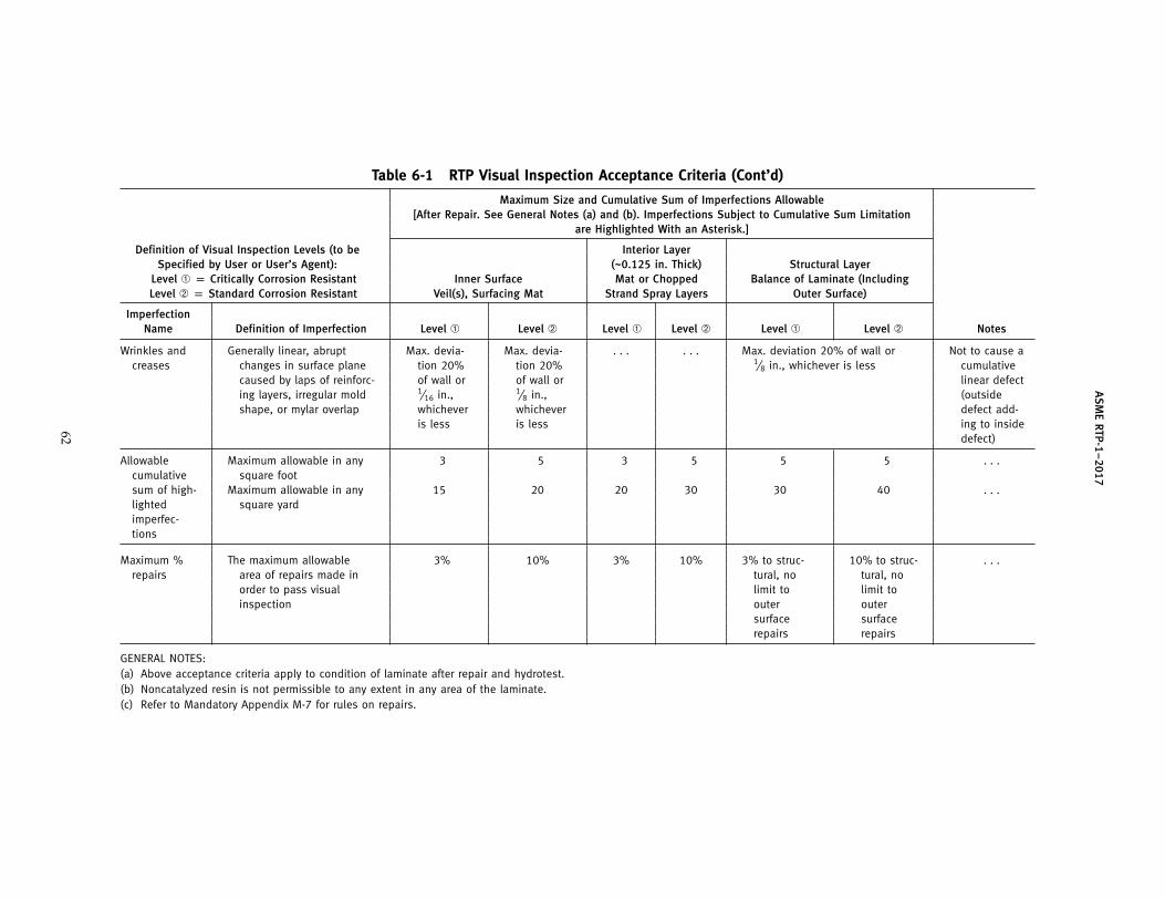
AS
ME
RTP-1–2017
Table 6-1 RTP Visual Inspection Acceptance Criteria (Cont’d)
Maximum Size and Cumulative Sum of Imperfections Allowable[After Repair. See General Notes (a) and (b). Imperfections Subject to Cumulative Sum Limitation
are Highlighted With an Asterisk.]
Definition of Visual Inspection Levels (to be Interior LayerSpecified by User or User’s Agent): (~0.125 in. Thick) Structural Layer
Level ➀ p Critically Corrosion Resistant Inner Surface Mat or Chopped Balance of Laminate (IncludingLevel ➁ p Standard Corrosion Resistant Veil(s), Surfacing Mat Strand Spray Layers Outer Surface)
ImperfectionName Definition of Imperfection Level ➀ Level ➁ Level ➀ Level ➁ Level ➀ Level ➁ Notes
Wrinkles and Generally linear, abrupt Max. devia- Max. devia- . . . . . . Max. deviation 20% of wall or Not to cause acreases changes in surface plane tion 20% tion 20% 1⁄8 in., whichever is less cumulative
caused by laps of reinforc- of wall or of wall or linear defecting layers, irregular mold 1⁄16 in., 1⁄8 in., (outsideshape, or mylar overlap whichever whichever defect add-
is less is less ing to insidedefect)
Allowable Maximum allowable in any 3 5 3 5 5 5 . . .cumulative square footsum of high- Maximum allowable in any 15 20 20 30 30 40 . . .lighted square yardimperfec-tions
Maximum % The maximum allowable 3% 10% 3% 10% 3% to struc- 10% to struc- . . .repairs area of repairs made in tural, no tural, no
order to pass visual limit to limit toinspection outer outer
surface surfacerepairs repairs
GENERAL NOTES:(a) Above acceptance criteria apply to condition of laminate after repair and hydrotest.(b) Noncatalyzed resin is not permissible to any extent in any area of the laminate.(c) Refer to Mandatory Appendix M-7 for rules on repairs.
62

ASME RTP-1–2017
WARNING: Suitable precautionary measures shall be taken toprotect personnel and property from a catastrophic implosionfailure during the test.
It should be noted that attainment of full vacuumis not practical. When the design vacuum cannot beachieved, the User or User’s Agent and the Fabricatorshall agree on the absolute internal pressure to beachieved during the test. Internal test pressure shall be12 psig or lower for vessels with a design vacuum thatexceeds 12 psig external pressure. Such agreement shallbe reached prior to the start of fabrication and shall bedocumented in the UBRS and pressure test inspectionreport.
(d) The Fabricator shall have written procedures forpressure testing. The test pressure shall be held for aminimum of 2 hr. No visible leakage is permissible dur-ing the 2-hr hold on an internal pressure test. Someleakage is permissible during a vacuum test, providedthe vacuum test pressure is held for the 2-hr minimum.(This may require continuous connection to the vacuumsource.) Subsequent to all pressure testing, the vesselshall pass a visual inspection per para. 6-940. Duringpressure testing, vessels shall be supported similar tothe way they will be supported in service (so that theloads imposed on the vessel and the supports are similarto those of the expected service loads). If the pressuretest generates an upward force, all anchor bolts shallbe secured. Vertical vessels may be hydrotested in thehorizontal position if agreed upon by the Owner and
63
Fabricator, and indicated in the UBRS. The pressure atthe highest point of the vessel in the test position shallbe equal to 110% to 120% of the total pressure (hydro-static plus design) at the lowest point in the designposition. The User is cautioned that the horizontal testof a vertical vessel will not simulate all of the loadingconditions of its final installed position.
(e) When it is not practical to conduct a pressure testuntil the equipment has been installed in service posi-tion, the test may be conducted at the installation site.
(f) The Inspector shall witness all pressure tests, ver-ify the test results, and record results of the test in theinspection report.
(g) If acoustic emission tests are required by the UBRSor are mandatory under design provisions of thisStandard [see para. 3B-500(c)], the Inspector shall wit-ness the tests and verify that the procedures used werein accordance with Mandatory Appendix M-8.
6-960 Procedures for Rectifying Nonconformities orImperfections
Mandatory Appendix M-7 describes approved proce-dures for rectifying nonconformities or imperfections.
Mandatory documentation requirements for rectify-ing nonconformities or imperfections are outlined inMandatory Appendix M-4, para. M4-400(e).
The Inspector shall include the documentation of non-conformity or imperfection rectification in the inspectionreport.
Get more FREE standards from Standard Sharing Group and our chats

ASME RTP-1–2017
Part 7Shop Qualification
7-100 SCOPE
This Part covers the requirements a Fabricator shallmeet in order to qualify capability in accordance withthis Standard. Included are the Fabricator’s facilities,personnel, Quality Control Program, and required dem-onstration of capability.
7-200 GENERAL
A Fabricator shall seek to fabricate vessels accordingto the rules of this Standard only in the general sizerange for which the shop has experience.
7-210 Shop Survey
Fabricators who desire a shop location to be certifiedaccording to the rules of this Standard shall be surveyedby an ASME survey team. The survey team shall verifythat all requirements of Parts 7 and 8 are met.
7-300 FABRICATOR’S FACILITIES AND EQUIPMENT
(a) The shop area and field site shall have designatedareas for
(1) storage of resin, catalyst, promoter, solvent, andother chemicals
(2) resin mixing and dispensing(3) bulk reinforcement and core material storage(4) tools and maintenance materials
(b) Head molds (other than cone shapes or flat covers)shall be as follows:
(1) ASME torispherical flanged and dished heads,a 2:1 semielliptical head, or a hemispherical head
(2) flanged flat head molds that will produce headsthat satisfy para. 3A-260 and Fig. 4-2
(c) Laboratory equipment shall be available for thequality control of bulk resin, reinforcing materials asreceived, and resin mixes as dispensed to fabricationpersonnel. Refer to Mandatory Appendices M-1 andM-2.
7-400 PERSONNEL
The Fabricator’s organization shall include specificpersonnel designated for each function listed below:
(a) Design and Drafting. As an alternative, this func-tion may be performed by outside qualified engineeringpersonnel. Design and drafting will be in accordancewith requirements in Parts 1, 3, 4, and 6 of this Standard.
64
(b) Quality Control. See Mandatory Appendix M-4.(c) Material Control and Issue. This will include mixing
and testing of resins, and inspection and cutting of rein-forcement. See Mandatory Appendices M-1 and M-2.
(d) Fabrication(e) Laminators and Secondary Bonders. Laminators and
Secondary Bonders shall be qualified in accordance withMandatory Appendix M-5.
7-500 QUALITY CONTROL PROGRAM, DOCUMENTHANDLING, AND RECORD SYSTEM
(a) The Fabricator shall establish and maintain aneffective Quality Control Program throughout all phasesof the fabricating process to ensure that all applicablerequirements of this Standard are met. Refer to Part 6,Mandatory Appendix M-4, and NonmandatoryAppendix NM-6.
(b) The Fabricator shall have a procedure that ensuresonly the most current revision of the latest and/or cor-rect drawings, specifications, purchase orders, and qual-ity control procedures are used for procurement,fabrication, and inspection purposes.
(c) A record keeping system satisfying the require-ments of this Standard shall be in use and available foraudit by the Certified Individual, the Inspector, and theUser’s representative.
7-600 DEMONSTRATION OF CAPABILITY(DEMONSTRATION LAMINATES)
(a) Each Fabricator’s shop shall demonstrate the abil-ity to fabricate laminates as required by the rules ofthis Standard. This initial demonstration qualifies theFabricator to produce laminates by those specific pro-cesses qualified for a maximum period of 5 yr.
(b) Each Fabricator’s shop must redemonstrate theability to fabricate laminates, as required by the rulesof this Standard, at no greater intervals than 5 yr. TheFabricator may redemonstrate the ability to fabricate alaminate using either of the following methods:
(1) produce acceptable demonstration laminates asrequired by the rules of this Standard for initialqualification
(2) provide acceptable Proof Tests for a specific typeof laminate and specific process per para. 6-930(d) [allrequirements of paras. 7-600 through 7-620 are met withthe completion of a successful Proof Test]
(17)

ASME RTP-1–2017
Table 7-1 Required Resins and Acceptable Fabrication Processes for Demonstration Laminates
Initial RedemonstrationDemonstration Laminate Min. Required Fabrication
Type Laminate Thickness, in. Resins Process[Note (1)] Thickness, in. [Note (2)] [Note (3)] [Note (4)] Qualification
Type I 0.48 0.25 1 polyester or 1, 2 All resins, all1 vinyl ester thicknesses
Type II 0.49 0.37 1 polyester or 1, 2 All resins, all1 vinyl ester thicknesses
Filament wound 0.37 min. 0.37 1 polyester or 3 All resins, all1 vinyl ester thicknesses
GENERAL NOTES:(a) A Fabricator must qualify all those fabrication processes planned to be used to construct vessels to this Standard.(b) For initial certification, see para. M6-200(b).
NOTES:(1) Designates laminate reinforcement type.(2) For redemonstration laminates, the fabrication process for Types I and II laminates may be 1 or 2.(3) Generic classes of resins required for qualification.(4) Process employed to produce the laminate:
1 — Hand lay-up.2 — Spray-up using a chopper gun device.3 — See para. 7-620(b).
(c) Subparts 2A and/or 2B provide specific rules gov-erning all laminates and refer to design basis laminatesthat a Fabricator is required to make in order to establishvalues for strength, thickness, and glass content. Thedemonstration laminates required by this Part are forthe purpose of qualifying the Fabricator and shop proce-dures. They may also be used to qualify Laminators (seeMandatory Appendix M-5). Demonstration laminatesand design basis laminates are not the same in purpose;hence requirements in terms of configuration, quantityto be produced, and tests may differ.
(d) Initial demonstration laminates and the redemon-stration of the Fabricator’s ability to fabricate laminatesare required for each type of laminate and each lami-nating process the Fabricator shall use on vessels fabri-cated to this Standard; refer to Table 7-1 [see (b)(2)].
(e) Each demonstration laminate shall be identifiedand labeled by the Fabricator in accordance withpara. 7-900.
(f) Demonstration laminates shall be tested in accor-dance with this Standard by an independent testinglaboratory. The independent testing laboratory shallreturn the remains of the demonstration laminate andspecimens with a certified written report. The reportshall state the results of the tests.
(g) A Fabricator’s shop is initially qualified to producea specific type of laminate by a specific process providedthe certified test report indicates that the demonstrationlaminate meets or exceeds the requirements of thisStandard (see para. 7-700).
65
(h) Upon the successful completion of aDemonstration Laminate Test Program, Fabricators shallcomplete a document of “Demonstration LaminateCertification.” This document is to be maintained withinthe Fabricator’s quality control files and a copy shall bemade available to a User, User’s Agent, or Inspector onrequest. In this document, the Fabricator shall certify,via the dated signature of his/her authorized agent, thefollowing:
(1) The demonstration laminate samples were con-structed according to all requirements of this Standard.
(2) Tests were conducted on the demonstrationlaminates according to all requirements of this Standard.
(3) The test data have been carefully examined bythe Fabricator, and the results are in accordance with allrequirements of this Standard.
(4) The next required date for demonstration ofcapability via demonstration laminates shall beindicated.
(5) Test reports from the independent testing labo-ratory are referenced by the specific date and/or refer-ence number within the certification document and acopy attached thereto.
7-610 Hand Lay-Up and Spray-Up DemonstrationLaminates
(a) All Fabricators shall produce and qualify handlay-up Types I and II laminates in accordance withrequirements in Tables 7-1 through 7-3.
Get more FREE standards from Standard Sharing Group and our chats
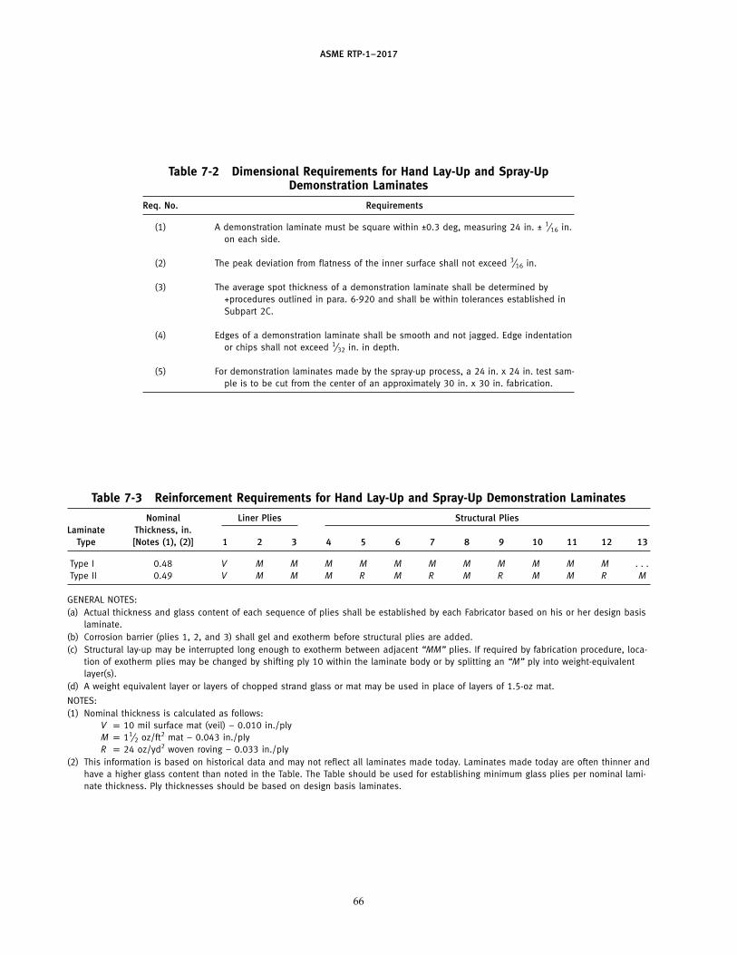
ASME RTP-1–2017
Table 7-2 Dimensional Requirements for Hand Lay-Up and Spray-UpDemonstration Laminates
Req. No. Requirements
(1) A demonstration laminate must be square within ±0.3 deg, measuring 24 in. ± 1⁄16 in.on each side.
(2) The peak deviation from flatness of the inner surface shall not exceed 3⁄16 in.
(3) The average spot thickness of a demonstration laminate shall be determined by+procedures outlined in para. 6-920 and shall be within tolerances established inSubpart 2C.
(4) Edges of a demonstration laminate shall be smooth and not jagged. Edge indentationor chips shall not exceed 1⁄32 in. in depth.
(5) For demonstration laminates made by the spray-up process, a 24 in. x 24 in. test sam-ple is to be cut from the center of an approximately 30 in. x 30 in. fabrication.
Table 7-3 Reinforcement Requirements for Hand Lay-Up and Spray-Up Demonstration Laminates
Nominal Liner Plies Structural PliesLaminate Thickness, in.
Type [Notes (1), (2)] 1 2 3 4 5 6 7 8 9 10 11 12 13
Type I 0.48 V M M M M M M M M M M M . . .Type II 0.49 V M M M R M R M R M M R M
GENERAL NOTES:(a) Actual thickness and glass content of each sequence of plies shall be established by each Fabricator based on his or her design basis
laminate.(b) Corrosion barrier (plies 1, 2, and 3) shall gel and exotherm before structural plies are added.(c) Structural lay-up may be interrupted long enough to exotherm between adjacent “MM” plies. If required by fabrication procedure, loca-
tion of exotherm plies may be changed by shifting ply 10 within the laminate body or by splitting an “M” ply into weight-equivalentlayer(s).
(d) A weight equivalent layer or layers of chopped strand glass or mat may be used in place of layers of 1.5-oz mat.
NOTES:(1) Nominal thickness is calculated as follows:
V p 10 mil surface mat (veil) − 0.010 in./plyM p 11⁄2 oz/ft2 mat − 0.043 in./plyR p 24 oz/yd2 woven roving − 0.033 in./ply
(2) This information is based on historical data and may not reflect all laminates made today. Laminates made today are often thinner andhave a higher glass content than noted in the Table. The Table should be used for establishing minimum glass plies per nominal lami-nate thickness. Ply thicknesses should be based on design basis laminates.
66

ASME RTP-1–2017
(b) Those Fabricators who plan to produce laminatesby the spray-up (chopper gun) process shall also pro-duce and qualify spray-up Types I and II laminates inaccordance with requirements in Tables 7-1 through 7-3.
(c) After fabrication, the Fabricator shall identify eachdemonstration laminate in accordance with the instruc-tions in para. 7-900.
(d) The quality control records shall contain a descrip-tion of the fabrication procedure used to produce eachdemonstration laminate.
(e) The mechanical properties of each demonstrationlaminate shall be determined in accordance withpara. 7-1000.
7-620 Filament Wound Demonstration Laminates
(a) Those Fabricators who plan to produce laminatesby the filament winding process shall produce and qual-ify filament wound laminates in accordance with therequirements in Table 7-1. Qualification for filamentwinding shall be in addition to qualification for Type Ior II laminates. Both qualifications are required forFabricators planning to construct filament woundvessels to this Standard, as Type I or II laminates arerequired for the fabrication of heads or when joiningthe subassemblies of vessels together.
(b) Since there are many process variations employedto produce filament wound laminates, each requiringdistinctly different tooling, controls, and skills, thisStandard requires that a Fabricator qualify all those pro-cess variations to be used in the construction of filamentwound vessels to this Standard.
Some examples of process variations, each requiringa demonstration laminate, are
(1) dry continuous filament winding(2) wet (bath) continuous filament winding(3) tape winding in conjunction with (b)(1) or (b)(2)(4) spray-up in conjunction with (b)(1) or (b)(2)
It is possible to qualify more than one of the abovevariables in a single demonstration laminate, so longas that resulting laminating process shall routinely beemployed to produce vessels to this Standard.
(c) Demonstration laminates shall have a Type I handlay-up or spray-up liner over which the structural fila-ment wound layer is applied. This liner shall exothermand cool before the structural filament wound layer isapplied.
(d) A minimum of one ply of 3⁄4-oz/ft2 chopped strandmat or an equivalent weight by the chopped spraymethod shall be applied over the liner immediatelybefore starting the filament wound structural layer.
(e) A filament wound demonstration laminate shallbe a 24 in. � 24 in. ±1⁄16 in. section cut from a hoop,wound on a mandrel with a minimum diameter of 8 ftto minimize the effects of curvature on sample testing.The width of the hoop shall be greater than 24 in. bya margin sufficient to avoid turnaround areas in the
67
24 in. � 24 in. cut section from which test samples shallbe taken.
(f) The thickness of the demonstration laminate shallbe 0.37 in. minimum, but may be increased up to 0.625 in.to allow for variations in winding or laminatingsequences that require thicknesses over 0.37 in. tocomplete.
(g) Filament wound demonstration laminates shall betested in accordance with para. 7-1000. Tensile strengthand tensile modulus per para. 7-1000(c) shall be obtainedin the axial direction only. Also, disregardpara. 7-1000(a)(2).
(h) Refer to para. 7-900(a)(4). Fabricators shall providea comprehensive description of the filament wound lam-inate sequence.
7-700 MINIMUM TEST VALUES FROMDEMONSTRATION LAMINATES
(a) Type I or II Demonstration Laminates(1) Dimensions shall be within tolerances outlined
in Table 7-2.(2) Barcol hardness readings shall show that 80%
of the readings meet or exceed 90% of the resin manufac-turer’s published casting hardness data.
(3) Tensile strength and tensile modulus valuesshall meet or exceed the values given in Table 2A-3.
(b) Filament Wound Demonstration Laminates(1) Dimensions shall be within tolerances outlined
in paras. 7-620(e) and (f).(2) Refer to (a)(2) for Barcol hardness requirements.(3) Axial tensile strength and tensile modulus val-
ues shall meet or exceed those values given for a Type Ilaminate in Table 2A-3.
7-800 DEMONSTRATION VESSEL
Fabricators shall design, fabricate, and satisfactorilytest a demonstration vessel in accordance with instruc-tions contained in Mandatory Appendix M-6.
The design and fabrication of the demonstration ves-sel requires a comprehensive understanding of thisStandard. It involves a full demonstration of theFabricator’s ability to design, execute drawings, qualifydemonstration laminates, establish design values fromdesign basis laminates, qualify Laminators andSecondary Bonders, and fabricate under effective over-view of the Fabricator’s Quality Control Program, all infull accordance with the requirements of this Standard.
No Fabricator shall claim qualification to fabricate tothis Standard until having satisfactorily completed andtested the demonstration vessel in accordance with theinstructions in Mandatory Appendix M-6.
Get more FREE standards from Standard Sharing Group and our chats
ASME RTP-1–2017
7-900 IDENTIFYING DEMONSTRATION LAMINATES
(a) Identification Report. A complete identificationreport shall accompany each demonstration laminate.This shall include the following:
(1) Fabricator’s shop name, address, phone number(2) identification of person fabricating the laminate(3) date the laminate was completed(4) fabrication process(5) description of fabrication materials used
(-a) resin manufacturer’s name and designationfor resin
(-b) generic class of resin(-1) polyester(-2) vinyl ester
(-c) reinforcement manufacturer’s name(s) anddesignation for reinforcement(s)
(b) Labeling. The Fabricator shall clearly label eachdemonstration laminate with the following:
(1) name of the Fabricator’s shop and identificationof person who fabricated the laminate
(2) date laminate was completed(3) type of laminate (Type I, Type II, filament
wound)(4) inner surface and outer surface shall be
identified(5) the two warp strand edges on Type II laminates,
and hoop and axial directions on filament wound lami-nates, shall be identified
(6) resin and reinforcement manufacturers andtheir Manufacturer’s Specific Product Identifications(MSPI)
7-1000 LABORATORY TEST AND TEST REPORTREQUIREMENTS FOR DEMONSTRATIONLAMINATES
The demonstration laminate specimen must be tested,and information recorded and reported, in accordancewith the following requirements:
(a) Dimensional Measurements of the DemonstrationLaminate
(1) The length and width of the demonstration lam-inate shall be measured and recorded.
(2) The flatness of the demonstration laminate shallbe determined by measuring the maximum possible gapunder a straightedge placed on the veil side and movedabout to achieve a maximum gap; this gap shall berecorded. (Disregard for filament wound laminates.)
(3) The average thickness of the demonstrationlaminate shall be determined using the procedures out-lined in para. 6-920(f)(2)(-a). All measurement data shallbe recorded. Measurements should be taken at theapproximate center of the demonstration laminate.
(4) The testing report shall summarize measure-ments taken and state compliance or nonconformance
68
with the requirements of this Standard. Reference ismade to Table 7-2, paras. 7-620(e) and (f ), andSubpart 2C.
(b) Barcol Hardness and Acetone Sensitivity Test(1) Barcol hardness shall be determined on the
demonstration laminate inner surface in accordancewith para. 6-910(b), and all Barcol readings shall berecorded.
(2) 80% of the Barcol hardness readings taken shallmeet or exceed 90% of the resin manufacturer’s pub-lished hardness data.
(3) An acetone sensitivity test shall be conductedin accordance with para. 6-910(b)(7).
(4) The testing report shall summarize the Barcolhardness measurements and the results of the acetonesensitivity test, and state compliance or nonconform-ance with the requirements of this Standard.
(c) Tensile Strength and Tensile Modulus of Elasticity(1) Tensile strength and tensile modulus of elastic-
ity shall be determined using the method given inASTM D638, ASTM D3039, or ASTM D5083.
(2) Test specimens shall be taken from equallyspaced areas on the demonstration laminate. Specimensmust be cut parallel to the edge of the laminate and theprocedure must not chip, tear, or degrade the specimens.Type II test specimens shall be cut parallel to the labeledwarp strand edge. The thickness of the specimens shallbe the full thickness of the laminate and must not bemachined on the inner or outer surfaces. Both hoop andaxial test coupons are required for anisotropic laminates.
(3) Test specimens shall be machined to the dimen-sions shown in Fig. 7-1.
(4) The testing report shall include the followingdata and shall state compliance or nonconformance withthe requirements of this Standard (see para. 7-700):
(-a) testing speed, in./min(-b) width and thickness of each specimen, in.(-c) peak load for each specimen, lb(-d) tensile strength of each specimen, psi(-e) tensile modulus of elasticity of each speci-
men, psi(-f) average tensile strength, psi(-g) average tensile modulus, psi
(d) Glass Content and Reinforcing Sequence(1) The glass content weight percent shall be deter-
mined by the method given in ASTM D2584.(2) A 1-in.-wide strip shall be cut from the demon-
stration laminate. This strip shall be cut into three 1-in.-long specimens.
(3) The testing report shall include the followingdata and shall state compliance or nonconformance withthe requirements of this Standard (see para. 7-700):
(-a) pyrolysis temperature.(-b) specimen weight before ignition, g.(-c) weight of specimen plus crucible, before igni-
tion and after ignition, g.
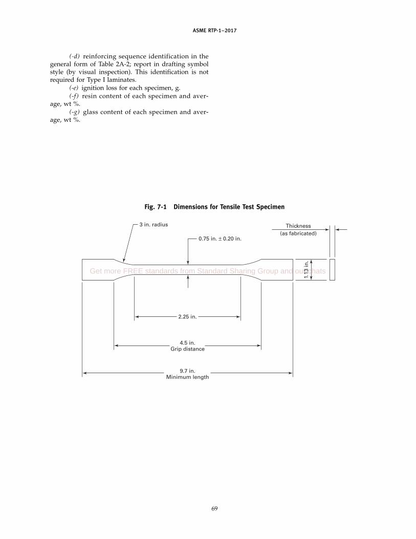
ASME RTP-1–2017
(-d) reinforcing sequence identification in thegeneral form of Table 2A-2; report in drafting symbolstyle (by visual inspection). This identification is notrequired for Type I laminates.
(-e) ignition loss for each specimen, g.(-f) resin content of each specimen and aver-
age, wt %.(-g) glass content of each specimen and aver-
age, wt %.
Fig. 7-1 Dimensions for Tensile Test Specimen
Thickness(as fabricated)
2.25 in.
1.13
in.
4.5 in.Grip distance
9.7 in.Minimum length
0.75 in. ± 0.20 in.
3 in. radius
69
Get more FREE standards from Standard Sharing Group and our chats

(17)
ASME RTP-1–2017
Part 8Certification
8-100 SCOPE
Part 8 provides rules for certification of Fabricatorsof RTP vessels.
8-200 GENERAL
A certified Fabricator is one who holds a validASME RTP-1 Certificate of Authorization. TheCertificate of Authorization permits the Fabricator tostamp the vessel with the ASME Certification Mark withRTP Designator, certifying that the vessel complies withall requirements of this Standard and ASME CA-1.
The responsibilities set forth herein relate only to com-pliance with this Standard and are not to be construedas involving contractual or legal liabilities.
8-300 CERTIFICATION PROCESS
8-310 Application
(a) Application for ASME RTP-1 Certification and theCertification Mark stamp shall be in accordance withASME CA-1, para. 2.1.
(b) When requested by the applicant on forms desig-nated by ASME, ASME will arrange for an evaluationof the applicant’s Quality Control Program and shopqualifications.
8-320 Quality Control Program
The Quality Control Program shall meet the require-ments of paras. 1-500, 8-325, and ASME CA-1, paras. 2.2and 2.3.
8-325 Changes to Quality Control Program. If theCertificate Holder wishes to make changes to the QualityControl Program, the Certificate Holder shall submit theproposed changes to ASME for approval, which shallaccept or reject them in writing.
8-330 Evaluation of Quality Control Program
Evaluation of the Quality Control Program shall meetthe requirements of ASME CA-1, paras. 2.2 and 2.3. Theacceptance by ASME of a Quality Control Program shallnot be interpreted to mean endorsement of technicalcapability to perform design work.
8-340 Evaluation of Shop Qualification
The evaluation shall be in accordance with Part 7.
70
8-350 Verification of Shop Qualification
An organization applying for a Certificate ofAuthorization shall have its shop(s) surveyed by anASME-approved survey team to ensure that all require-ments of the Standard are met.
8-400 ASME RTP-1 CERTIFICATE OFAUTHORIZATION HOLDER
A Fabricator shall obtain a valid Certificate ofAuthorization in accordance with para. 1-520 andASME CA-1, in order to stamp the vessel.
8-410 Additional Responsibilities of the ASME RTP-1Certificate Holder
Responsibilities include the following:(a) evaluation and approval of material manufactur-
ers, and suppliers of parts and subcontracted services,in accordance with Mandatory Appendix M-4
(b) establishing and maintaining a Quality ControlProgram in accordance with Mandatory Appendix M-4
(c) preparing and filing a Quality Control Programmanual per ASME CA-1, para. 2.3.4 and Table 1
(d) furnishing the User or User ’s Agent with theappropriate Fabricator’s Data Report(s)
(e) capability of testing per para. 6-950(f) ability to meet the requirements of ASME CA-1,
paras. 2.1, 5.2, and 5.3
8-420 Subcontracting
The Fabricator completing any vessel to be markedwith the ASME Certification Mark with RTP Designatorhas the responsibility of ensuring that any work doneby others complies with all the requirements of thisStandard and ASME CA-1.
8-500 ISSUANCE OF CERTIFICATION
The requirements of ASME CA-1, para. 2.4 shall apply.
8-550 Maintaining Certification
The requirements of ASME CA-1, para. 2.5 shall apply.
8-560 Renewal of Certification
The requirements of ASME CA-1, para. 2.6 shall apply.
8-570 Suspension of Certification
The requirements of ASME CA-1, para. 2.7 shall apply.
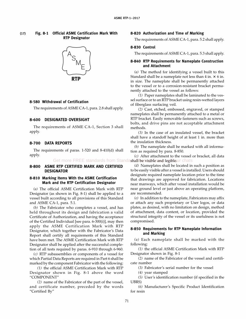
(17)
ASME RTP-1–2017
Fig. 8-1 Official ASME Certification Mark WithRTP Designator
RTP
8-580 Withdrawal of Certification
The requirements of ASME CA-1, para. 2.8 shall apply.
8-600 DESIGNATED OVERSIGHT
The requirements of ASME CA-1, Section 3 shallapply.
8-700 DATA REPORTS
The requirements of paras. 1-520 and 8-410(d) shallapply.
8-800 ASME RTP CERTIFIED MARK AND CERTIFIEDDESIGNATOR
8-810 Marking Items With the ASME CertificationMark and the RTP Certification Designator
(a) The official ASME Certification Mark with RTPDesignator (as shown in Fig. 8-1) shall be applied to avessel built according to all provisions of this Standardand ASME CA-1, para. 5.1.
(b) The Fabricator who completes a vessel, and hasheld throughout its design and fabrication a validCertificate of Authorization, and having the acceptanceof the Certified Individual [see para. 6-300(i)], may thenapply the ASME Certification Mark with RTPDesignator, which together with the Fabricator’s DataReport shall certify all requirements of this Standardhave been met. The ASME Certification Mark with RTPDesignator shall be applied after the successful comple-tion of all tests required by paras. 6-910 through 6-960.
(c) RTP subassemblies or components of a vessel forwhich Partial Data Reports are required in Part 6 shall bemarked by the component Fabricator with the following:
(1) the official ASME Certification Mark with RTPDesignator shown in Fig. 8-1 above the word“COMPONENT”
(2) name of the Fabricator of the part of the vessel,and certificate number, preceded by the words“Certified By”
71
8-820 Authorization and Time of Marking
The requirements of ASME CA-1, para. 5.2 shall apply.
8-830 Control
The requirements of ASME CA-1, para. 5.3 shall apply.
8-840 RTP Requirements for Nameplate Constructionand Attachment
(a) The method for identifying a vessel built to thisStandard shall be a nameplate not less than 4 in. � 6 in.in size. The nameplate shall be permanently attachedto the vessel or to a corrosion-resistant bracket perma-nently attached to the vessel as follows:
(1) Paper nameplates shall be laminated to the ves-sel surface or to an RTP bracket using resin-wetted layersof fiberglass surfacing veil.
(2) Cast, etched, embossed, engraved, or stampednameplates shall be permanently attached to a metal orRTP bracket. Easily removable fasteners such as screws,bolts, and drive pins are not acceptable attachmentmethods.
(3) In the case of an insulated vessel, the bracketshall have a standoff height of at least 1 in. more thanthe insulation thickness.
(b) The nameplate shall be marked with all informa-tion as required by para. 8-850.
(c) After attachment to the vessel or bracket, all datashall be visible and legible.
(d) Nameplates shall be located in such a position asto be easily visible after a vessel is installed. Users shoulddesignate required nameplate location prior to the timethat drawings are approved for fabrication. Locationsnear manways, which after vessel installation would benear ground level or just above an operating platform,are recommended.
(e) In addition to the nameplate, Fabricators may affixor attach any such proprietary or User logos, or dataplates, as desired, with no limitation on design, methodof attachment, data content, or location, provided thestructural integrity of the vessel or its usefulness is notcompromised.
8-850 Requirements for RTP Nameplate Informationand Marking
(a) Each nameplate shall be marked with thefollowing:
(1) the official ASME Certification Mark with RTPDesignator shown in Fig. 8-1
(2) name of the Fabricator of the vessel and certifi-cate number
(3) Fabricator’s serial number for the vessel(4) year stamped(5) User’s identification number (if specified in the
UBRS)(6) Manufacturer’s Specific Product Identification
for resin
Get more FREE standards from Standard Sharing Group and our chats
ASME RTP-1–2017
(7) appropriate Visual Inspection Level (Level 1 orLevel 2)
(8) for vessels defined as “Atmospheric” in theUBRS (see also para. 3-300), the words
(-a) “Design Pressure — Atmospheric”(-b) “Maximum Temperature”
(9) for other vessels(-a) “Maximum Allowable Working Pressure at
Maximum Temperature”(-b) “Maximum Allowable External Working
Pressure at Maximum Temperature”(10) design basis specific gravity of contents(11) the designation “Critical Service” if applicable
Specified pressures shall be gage pressures given inunits as specified in the UBRS. Temperatures shall bein units specified in the UBRS.
(b) If the vessel is optionally registered, the NationalBoard Mark and Registration Number shall be stampedon the nameplate. The legend “National Board Registra-tion Number” is optional.
(c) Letters and figures indicating specific vesseldesign data shall be at least 5⁄16 in. high. Preprintedlegend letters and figures shall be at least 1⁄8 in. high.
72
8-860 Requirements for RTP Nameplate Design
(a) Paper Nameplates(1) Paper shall be at least 0.004 in. thick and of high
quality, white bond or linen base.(2) All markings shall be black, highly visible and
readable, on a white background.(3) Markings, including the ASME Certification
Mark with RTP Designator, shall be made in indelibleink of such nature as not to be water or resin soluble.
(b) Cast, Etched, Embossed, Engraved, or StampedNameplates
(1) Material shall be 300 series stainless steel orother suitable corrosion-resistant material.
(2) Thickness shall be sufficient to resist distortiondue to the application of the marking, but in no caseshall be less than 0.020 in.
(3) Markings including the RTP Designator may beproduced by casting, etching, embossing, stamping, orengraving. The ASME Certification Mark shall bestamped. All stamps for applying the ASMECertification shall be obtained from ASME.
ASME RTP-1–2017
MANDATORY APPENDIX M-1REINFORCEMENT MATERIALS RECEIVING PROCEDURES
M1-100 INTRODUCTION
All inspections and tests specified in this Appendixare to be performed by Fabricator personnel or an inde-pendent testing laboratory.
ARTICLE AFIBERGLASS SURFACING VEIL,
ORGANIC FIBER SURFACING VEIL,CARBON FIBER VEIL, AND
FIBERGLASS CHOPPED STRAND MAT
M1A-100 INTRODUCTION
This Article specifies the minimum inspections andtests that shall be performed on the rolls of fiberglasssurfacing veil, organic fiber surfacing veil, and fiberglasschopped strand mat that shall be used to fabricate equip-ment to this Standard.
M1A-200 ACCEPTANCE INSPECTION
Acceptance inspection shall include inspection of allrolls for proper packaging and identification, and con-tamination. This acceptance inspection is to be con-ducted on the unopened roll. Acceptance requirementsand limits are as defined in para. M1A-410. Acceptanceinspection shall include inspection of selected rolls formeasurement of unit weight per ASQ Z1.4 criteria.Inspection for manufacturing imperfections shall be con-ducted during use of rolled goods. Acceptance require-ments and limits are as defined in paras. M1A-420 andM1A-430.
The form shown in Table M1A-1, or a similar formthat contains the provisions to record the results of theserequired inspections and certifications, if applicable,shall be used by the Fabricator and shall be retained inthe inspection records. A separate form shall be usedfor each mat manufacturer, mat nomenclature, mat treat-ment, and mat unit weight.
In lieu of performing the above manufacturing inspec-tions, measurements, and documentation, the Fabricatorshall provide the User or User’s Agent with a Certificateof Compliance from the material manufacturer. ThisCertificate shall ensure that materials were manufac-tured, inspected, and tested per the material supplier’sspecifications.
73
M1A-300 EQUIPMENT AND MEASURING TOOLSREQUIRED
M1A-310 Inspection Table and Lights
An inspection table and adequate overhead lightingthat are suitable for the inspection and testing of the matare required. The equipment used must not introducecontamination to the mat during inspection and testing.
M1A-320 Linear Measuring Tools
A standard linear measuring tool (longer than thewidth of the rolls) that measures the roll widths withminimum accuracy of ±1⁄8 in. is required. A 12 in. ±1⁄32 in.� 12 in. ±1⁄32 in. template is required.
M1A-330 Laboratory Balance
A laboratory balance that measures to 0.1 g is required.
M1A-400 PROCEDURES AND ACCEPTANCE LIMITS
M1A-410 Roll Identification and Package Inspection
The mat shall be packaged as shipped from the matmanufacturer’s factory. If repackaging is required, theFabricator shall ensure that a material Certificate ofCompliance traceable to the original material is pro-vided. The original labels can be modified in regards tonumber and width of rolls only. All other documentationshall remain unchanged. Verify and enter in the inspec-tion record that the mat rolls as identified by the matmanufacturer have the same nomenclature as the matspecified to produce the laminate by Subparts 2A and 2B,and examine the packaging of the mat for damage thatrenders the mat unusable. Indicate acceptable rolls byrecording the date and name of the person performingthe examination in Table M1A-1, column 4.
For packaged mats that are found to be acceptablefor further inspection and tests, enter the reinforcementproduction date and lot number in Table M1A-1,columns 2 and 3.
M1A-420 Visual Inspection of Mat
(a) As the mat is used during fabrication, it shall bevisually inspected for imperfections and contamination.Date and name of person performing visual inspectionshall be recorded in Table M1A-1, column 8.
(b) The mat shall be uniform in color, texture, andappearance. Imperfections and/or contaminants shallbe removed so as not to damage the mat or by making
Get more FREE standards from Standard Sharing Group and our chats

ASME RTP-1–2017
Table M1A-1 Veil and Mat Reinforcement Log Sheet
Fabricator’s name Mat manufacturer
Address Mat nomenclature
Mat treatment (if given) [Note (1)]
QC file no. Mat weight [Note (2)]
1 2 3 4 5 6 7 8
Roll Reinforcement Lot No. Packaging Width Weight of Property VisualNo. Production Date [Note (1)] Inspection sq ft Inspection Inspection
(if Given) Sample (Cols. 5 and 6)
By Date By Date By Date
1
2
3
4
5
6
7
8
Comments on visual and packaging inspection (indicate which roll):
GENERAL NOTE: This form may be reproduced and used without written permission from ASME if used for purposes other than republication.
NOTES:(1) Lot, batch, product code, or other label identification.(2) Manufacturer’s label weight.
74

ASME RTP-1–2017
two parallel cuts across the width of the mat and dis-carding the rectangular section of the mat containingthe defects. Contaminants do not include white or lightgray binder spots.
NOTE: Examples of imperfections are holes, cuts, thin spots, ordelaminations, i.e., separating into layers during unrolling. Exam-ples of contaminants are dirt, oil, grease, and foreign objects.
(c) Rolls having any of the following defects shall notbe used in laminates made to this Standard:
(1) wet spots(2) water contamination(3) bar marks(4) lengthwise wrinkles exceeding 5 ft in length
M1A-430 Weight per Square Foot of Mat
From the leading edge of each roll of mat that will betested as per para. M1A-200, cut a 1-ft2 (10-ft2 for surfac-ing veil) sample using the template specified inpara. M1A-320. If the roll is less than 12 in. wide, usethe full width of the roll, but adjust the length of thesample (use the linear measuring tool specified inpara. M1A-320). Any property measurement shall beconducted by unrolling only the quantity of materialrequired to conduct the test. Using the laboratory bal-ance required by para. M1A-330, weigh the sample ofmat to the nearest 0.1 g. Convert the grams to ounces,if needed, by multiplying grams by 0.0352. If the samplefrom a roll falls outside the mat manufacturer’s specifiedweight range, the roll of mat shall be rejected. Enter thevalues of weighed samples for acceptable and unaccept-able rolls in the inspection form in Table M1A-1, col-umn 6. Note the rejected rolls with the word “rejected”next to the recorded weight in column 6.
ARTICLE BFIBERGLASS SPRAY-UP ROVING
AND FILAMENT WINDING ROVING
M1B-100 INTRODUCTION
This Article specifies the minimum inspections andtests that are to be performed on fiberglass spray-uproving and filament winding roving that are to be usedto fabricate equipment to this Standard.
M1B-200 ACCEPTANCE INSPECTIONS
Acceptance inspections shall include inspection of theroving balls for proper packaging, identification, andcontamination. This acceptance inspection is to be con-ducted on the unopened roll. Acceptance requirementsand limits are as defined in para. M1B-410. Acceptanceinspection shall include inspection of selected rolls formeasurement of roving yield per ASQ Z1.4 criteria.
75
Inspection for manufacturing imperfections shall be con-ducted during use of roving balls. Acceptance require-ments and limits are as defined in paras. M1B-420 andM1B-430.
The form shown in Table M1B-1, or a similar formthat contains the provisions to record the results ofinspections, shall be used by the Fabricator and shall beretained in the inspection records. A separate form shallbe used for each roving manufacturer, roving nomencla-ture, and roving yield.
In lieu of performing the above inspections, measure-ments, and documentation, the Fabricator shall providethe User or User ’s Agent with a Certificate ofCompliance from the material manufacturer. ThisCertificate shall ensure that materials were manufac-tured, inspected, and tested per the material supplier’sspecifications.
M1B-300 EQUIPMENT AND MEASURING TOOLS
M1B-310 Wrap Reel
A device may be used that provides a minimum of a6 yd sample measured and cut under sufficient tensionto keep the strand taut. Equipment such as standard36-in. or 54-in. (1-yd or 1.5-yd) yarn reel with adjustabletransverse, four skein capacity is suggested.
M1B-320 Laboratory Balance
A laboratory balance that measures to 0.1 g is required.
M1B-400 PROCEDURES AND ACCEPTANCE LIMITS
M1B-410 Roving Identification and PackageInspection
The roving shall be packaged as shipped from themanufacturer’s factory. The roving shall not be repack-aged in the distribution of the material after the manu-facturer has shipped the roving. Verify that the rovingballs as identified by the manufacturer have the samenomenclature as the roving required by Part 2 and exam-ine the packaging of the roving for damage that rendersthe roving unusable. Indicate acceptable roving byrecording in Table M1B-1, column 4, the date and nameof the person performing the examination.
For packaged rovings that are found to be acceptablefor further inspection and tests, enter the reinforcementproduction date and lot number for each ball inTable M1B-1, columns 2 and 3.
M1B-420 Visual Inspection of Roving
(a) The roving ball shall be visually inspected forimperfections and contamination prior to use by theFabricator. Record the date and the inspector’s name inTable M1B-1, column 7. If any roving ball is rejected,record the reason in the comments section inTable M1B-1.
Get more FREE standards from Standard Sharing Group and our chats

ASME RTP-1–2017
Table M1B-1 Roving Reinforcement Log Sheet
Fabricator’s name Roving manufacturer
Address Roving nomenclature
Roving yield
QC file no.
1 2 3 4 5 6 7
Ball Reinforcement Lot No. Packaging Yield Property VisualNo. Production Date [Note (1)] Inspection Inspection Inspection
(if Given) (Column 5)
By Date By Date By Date
1
2
3
4
5
6
7
8
Comments on visual and packaging inspection (indicate which roll):
GENERAL NOTE: This form may be reproduced and used without written permission from ASME if used for purposes other than republication.
NOTE:(1) Lot, batch, product code, or other label identification.
76

ASME RTP-1–2017
(b) Roving balls having any of the following defectsshall not be used for laminates made to this Standard:
(1) any package that exhibits foreign matter suchas dirt, oil, grease, waste glass fiber, or beads of glasssuch that it would detract from the performance orappearance of the finished product
(2) balls that have been contaminated by water
M1B-430 Measurement of Roving Yield
From one roving ball per shipment, obtain a minimumof a 6 yd sample (length A) of roving as required bypara. M1B-310. Roving shall be pulled from the sameside of the package as used in the Fabricator’s process.If the roving is pulled from the outside of the package,sufficient material shall be removed and discarded sothat the sample will be taken from undisturbed material.Remove the sample from the wrap reel. Double the sam-ple several times and tie with a single knot. Using thebalance required by para. M1B-320, weigh the sampleto the nearest 0.1 g. Convert grams to ounces by multi-plying grams by 0.0352. Two specimens from each pack-age shall be measured and the average computed.Record as weight A.
Calculate the yield, yd/lb, using the followingformula:
yield, yd/lb p16 oz/lb � length A
weight A (oz)p
96weight A (oz)
Enter the yield of acceptable and unacceptable ballsof roving in Table M1B-1, column 5. If the yield of theball of roving is outside the manufacturer’s specification,the remaining balls in the shipment are to be inspectedper ASQ Z1.4 criteria, following the procedure specifiedin this paragraph. Balls whose yield is outside the manu-facturer’s specification shall not be used for laminatesmade to this Standard. Note the rejected roving ballswith the word “rejected” next to the yield in column 5.Also, record the date and name of the person performingthe yield measurement in column 6.
ARTICLE CFIBERGLASS WOVEN ROVING FABRIC,FIBERGLASS UNIDIRECTIONAL FABRIC,AND FIBERGLASS NONWOVEN BIAXIAL
FABRICM1C-100 INTRODUCTION
This Article specifies the minimum inspections andtests that are to be performed on the rolls of fiberglasswoven roving fabric, fiberglass unidirectional fabric, andfiberglass nonwoven biaxial fabric that are to be usedto fabricate equipment to this Standard.
M1C-200 ACCEPTANCE INSPECTIONS
Acceptance inspections shall include inspection of allfabric rolls for proper packaging and identification, and
77
contamination. This acceptance inspection is to be con-ducted on the unopened roll. Acceptance requirementsand limits are as defined in para. M1C-410. Acceptanceinspection shall include inspection of selected rolls formeasurement of unit weight and verification of construc-tion of fabric per ASQ Z1.4 criteria. Inspection for manu-facturing imperfections shall be conducted during useof rolled goods. Acceptance requirements and limits areas defined in paras. M1C-420 through M1C-450.
The form shown in Table M1C-1, or a similar formthat contains the provisions to record the results of theserequired inspections, shall be used by the Fabricator andshall be retained in the inspection records. A separateform shall be used for each fabric manufacturer, fabricnomenclature, fabric unit weight (oz/yd2), and fabricconstruction.
In lieu of performing the above inspections, measure-ments, and documentation, the Fabricator shall providethe User or User ’s Agent with a Certificate ofCompliance from the material manufacturer. ThisCertificate shall ensure that materials were manufac-tured, inspected, and tested per the material supplier’sspecifications.
M1C-300 EQUIPMENT AND MEASURING TOOLSREQUIRED
M1C-310 Inspection Table and Lights
An inspection table and adequate overhead lightingthat are suitable for the inspection and testing of thefabric are required. The equipment used shall not intro-duce contamination to the fabric during inspection andtesting.
M1C-320 Linear Measuring, Marking, and CuttingTools
(a) A standard linear measuring tool (longer thanwidth of roll) that measures the roll widths with mini-mum accuracy of ±1⁄8 in. is required.
(b) A 3 in. ± 1⁄32 in. square template is required.(c) A fine-point felt-tip pen and scissors are required.
M1C-330 Laboratory Balance
A laboratory balance that measures to 0.1 g is required.
M1C-400 PROCEDURES AND ACCEPTANCE LIMITS
M1C-410 Roll Identification and Package Inspection
The fabric shall be packaged as shipped from themanufacturer’s factory. The fabric shall not be repack-aged in the distribution of the material after the manu-facturer has shipped the fabric. Verify that the fabricrolls as identified by the manufacturer have the samenomenclature as the fabric required by Part 2, and exam-ine the packaging of the fabric for damage that rendersthe fabric unusable. Indicate acceptable rolls by
Get more FREE standards from Standard Sharing Group and our chats

ASME RTP-1–2017
Table M1C-1 Fabric Reinforcement Log Sheet
Fabricator’s name Fabric manufacturer
Address Fabric nomenclature
Fabric weight
QC file no. Fabric construction
1 2 3 4 5 6 7 8 9
Roll Reinforcement Lot No. Packaging Width Weight Construction Property VisualNo. Production [Note (1)] Inspection Inspection Inspection
Date (Cols. 5, 6,(if Given) and 7)
By Date By Date By Date
1
2
3
4
5
6
7
8
Comments on visual and packaging inspection (indicate which roll):
GENERAL NOTE: This form may be reproduced and used without written permission from ASME if used for purposes other than republication.
NOTE:(1) Lot, batch, product code, or other label identification.
78

ASME RTP-1–2017
recording the date and name of the person performingthe examination in Table M1C-1, column 4.
For packaged rolls that are found to be acceptable forfurther inspection and tests, enter the fabric productiondate and lot number in Table M1C-1, columns 2 and 3.
M1C-420 Visual Inspection of Fabric
(a) As fabric is used, it shall be visually inspectedfor imperfections and contaminations by the Fabricator.Record date and name of inspector in Table M1C-1,column 9. If a roll is rejected, record the reason underthe comments section in Table M1C-1.
(b) Fabric shall be uniform in color, texture, andappearance. The following imperfections and/or con-taminations shall be removed from fiberglass wovenroving and fiberglass nonwoven biaxial fabric by makingtwo parallel cuts across the width of the fabric anddiscarding the rectangular sections of fabric containingthe following defects:
(1) dirt spots (3⁄16 in. to 3⁄4 in. in diameter) in excessof one per 10 lineal feet (dirt spots are defined as allforeign matter, dirt, grease spots, etc.)
(2) missing ends for more than 2 consecutive feetin length
(3) fuzz clumps or loops greater than 1 in. in heightfrom the surface
(c) Fiberglass woven and fiberglass nonwoven biaxialfabric having any of the following defects shall not beused for laminates made to this Standard:
(1) dirt spots in excess of 3⁄4 in. in diameter (dirt spotsare defined as all foreign matter, dirt, grease spots, etc.)
(2) more than 11 missing ends, either individualpicks or any combination of individual and multiple(2, 3, 4, or 5) ends in any consecutive 100 lineal feet
(3) fuzz clumps or loops that prevent the properlay-down of the fabric and that cannot be easily removed
(4) rolls that have been contaminated by water(d) Fiberglass unidirectional fabric shall be uniform
in color, texture, and appearance. The following imper-fections and/or contaminations shall be removed fromthe fabric by making two parallel cuts across the widthof the fabric and discarding the rectangular sections offabric containing the following defects:
(1) dirt spots (3⁄16 in. to 3⁄4 in. in diameter) in excessof one per 10 lineal feet (dirt spots are defined as allforeign matter, dirt, grease spots, etc.).
(2) missing ends in any direction less than one perlineal foot.
(3) areas of the fabric less than 6 in. � 6 in. whererovings are disoriented or looped less than 1 in. in heightfrom the surface. The number of these areas shall notexceed two per 5 lineal yards of fabric. If so, the rollshall not be used for laminates made to this Standard.
(4) weft tails exceeding 1 in. or less than 1⁄8 in. inlength.
79
(5) bias exceeding ±10 deg from 0 deg/180 deg ina warp (machine direction) product or from90 deg/270 deg in a weft (fill direction) product.
(e) Fiberglass unidirectional fabric rolls having any ofthe following defects shall not be used for laminatesmade to this Standard:
(1) dirt spots in excess of 3⁄4 in. in diameter (dirt spotsare defined as all foreign matter, dirt, grease spots, etc.)
(2) missing ends in any direction more than oneper lineal foot of fabric
(3) areas of the fabric greater than 6 in. � 6 in.where rovings are disoriented or looped less than 1 in.in height from the surface
(4) areas of the fabric where rovings are disorientedor looped greater than 1 in. in height from the surface
(5) rolls that have been contaminated by water orother substances
M1C-430 Width Measure of Fabric
With the linear measuring tool given in para.M1C-320, measure the width of the fabric at least 1 ydfrom the beginning (leading) edge of the roll and attwo additional positions at least 6 in. apart. Follow themanufacturer’s definition for the width of the particularfabric (see note below). Measure to the nearest 1⁄8 in.Average the three measurements and enter the measuredwidth of acceptable and unacceptable rolls in the inspec-tion form shown in Table M1C-1. Note the rejected rollswith the word “rejected” next to the width in column5. Rolls with variations greater than ±1⁄2 in. shall not beused in laminates made to this Standard.
Record the date and name of the person performingthe width, weight, and construction measurements incolumn 8.
NOTE: Due to the methods of manufacturing fabrics, there aredifferent ways of describing widths of fabrics.
M1C-440 Weight per Square Yard of Fabric
Unroll the fabric on the inspection table and lay flat.Pull one fill pick from the sample or mark a line acrossthe width of the fabric. Measure from the pulled pickor line using a 36-in. rule meeting the accuracy require-ments of para. M1C-320. Pull another fill pick or markoff the 36-in. sample for cutting. Cut the 36-in.-longsample across the width of the fabric using scissors.Measure the width of the fabric according topara. M1C-430. Weigh the sample to the nearest 0.1 g.Convert grams to ounces by multiplying grams by0.0352. Calculate the weight per square yard in ouncesper square yard using the following formula:
weight, ozsquare yard
p36 in.
square yard�
sample weight, ozsample width, in.
Rolls whose weight per square yard are outside themanufacturer’s specification shall not be used for lami-nates made to this Standard. Enter the weight per square
Get more FREE standards from Standard Sharing Group and our chats
ASME RTP-1–2017
yard of acceptable and unacceptable rolls in the inspec-tion report shown in Table M1C-1. Note the rejectedrolls with the word “rejected” next to the weight incolumn 6.
M1C-450 Construction
Unroll the fabric on the inspection table and lay flat.Perform the verification of construction in an area atleast 1 yd from the beginning of the roll and one-tenthof the width from the edge of the fabric. For example,on 60 in. material start at least 6 in. from one edge and1 yd from the beginning of the fabric. Using the templaterequired by para. M1C-320, measure a 3-in. square andcount the number of warp strands (if applicable) to thenearest half strand in the section. Repeat this three timesdiagonally across the fabric. Add the total warp strandscounted in the three 3-in. squares and divide by nine.This will give picks per inch in the warp of the fabric.Repeat for the fill (weft) strands if applicable. Rollswhose picks per inch in either warp or fill are outsidethe manufacturer’s specification shall not be used forlaminates made to this Standard. Enter the picks perinch in the warp and fill of acceptable and unacceptablerolls to the nearest 0.1 picks in Table M1C-1, column 7.
ARTICLE DFIBERGLASS MILLED FIBERS
M1D-100 INTRODUCTION
This Article specifies the minimum inspections andtests that are to be performed on the packages of fiber-glass milled fiber that are to be used to fabricate equip-ment to this Standard.
M1D-200 ACCEPTANCE INSPECTIONS
Acceptance inspections shall include inspection of themilled fiber for proper packaging and identification, andvisual inspection for contamination. Acceptancerequirements and limits are defined in paras. M1D-410and M1D-420(a).
80
The form shown in Table M1D-1, or a similar formthat contains the provisions to record the results of theserequired inspections, shall be used by the Fabricator andshall be retained in the inspection records. A separateform shall be used for each milled fiber manufacturer,milled fiber nomenclature, and milled fiber length.
M1D-300 EQUIPMENT REQUIRED
An inspection table and adequate overhead lightingthat are suitable for the inspection of the milled fiberare required. The equipment used must not introducecontamination to the milled fiber during inspection.
M1D-400 PROCEDURES AND ACCEPTANCE LIMITS
M1D-410 Package Identification and Inspection
The milled fiber shall be packaged as shipped fromthe manufacturer’s factory. The milled fiber shall not berepackaged in the distribution of the material after themanufacturer has shipped the milled fiber. Verify thatthe milled fiber as identified by the manufacturer hasthe same nomenclature as the milled fiber required byPart 2, and examine each package of milled fiber fordamage that renders it unusable. Indicate acceptablemilled fibers by recording date and name of the personperforming the examination in Table M1D-1, column 4.
For packaged milled fiber that is found to be accept-able for further inspection, enter the reinforcement pro-duction date and lot number for each package of milledfibers used in Table M1D-1, columns 2 and 3.
M1D-420 Visual Inspection of Milled Fiber
(a) As milled fiber is used, it shall be visuallyinspected for contamination by the Fabricator. Recordthe date and the inspector ’s name in Table M1D-1,column 5.
(b) Packages having contamination of the milled fiberevident in the form of water, oil, grease, or clumpingtogether shall be rejected.
(c) Record the results of the visual inspection of eachpackage of milled fiber in the inspection report.

ASME RTP-1–2017
Table M1D-1 Milled Fiber Reinforcement Log Sheet
Fabricator’s name Fiber manufacturer
Address Fiber nomenclature
Fiber length
QC file no.
1 2 3 4 5
Package Reinforcement Production Date Lot No. Packaging VisualNo. (if Given) [Note (1)] Inspection Inspection
By Date By Date
1
2
3
4
5
6
7
8
Comments on visual and packaging inspection (indicate which package):
GENERAL NOTE: This form may be reproduced and used without written permission from ASME if used for purposes other than republication.
NOTE:(1) Lot, batch, product code, or other label identification.
81
Get more FREE standards from Standard Sharing Group and our chats

ASME RTP-1–2017
MANDATORY APPENDIX M-2MATRIX MATERIALS RECEIVING PROCEDURES
M2-100 INTRODUCTION
This Appendix’s Articles A (Visual InspectionRequirements), B (Specific Gravity), C (Viscosity,Brookfield Method), and D (Room Temperature GelTime) specify the minimum requirements for the inspec-tions and tests that shall be performed by the Fabricatoror an independent testing laboratory on resins and cur-ing agents (curing agents include accelerators, promot-ers, and peroxides as required for specific resinssystems).
The Fabricator may use a Certificate of Analysis pre-pared by the manufacturer as a means of satisfying therequirements of Mandatory Appendix M-2, M2-100 andArticles A through D in lieu of inspections and testsbeing performed by the Fabricator or an independenttesting laboratory on resins and curing agents, underthe following conditions:
(a) The product is accompanied by a manufacturer’sprepared Certificate of Analysis, which states the testmethods and procedures were followed to obtain theresults.
(b) The Fabricator accepts the Certificate of Analysis.(c) The Fabricator determines the products are the
ones that were ordered and they meet the labelingrequirements of Mandatory Appendix M-2, Article Awith the following exceptions:
(1) M2A-200(a)(3): the appearance (color, clarity,absence of solids, gels, and dirt) may be determined bythe manufacturer.
(2) M2A-200(a)(4): specific gravity, viscosity, androom temperature gel time may be determined bytest methods established and performed by themanufacturer.
(3) M2A-200(a)(5): results of specific tests need notbe recorded on the Resin Log Sheet (Table M2E-1), pro-vided the Certificate of Analysis is noted in the LogSheet by a traceable identification and is available forreview by concerned parties.
(4) M2A-200(b)(6): testing of proper curing activityneed not be performed on curing agents by theFabricator nor recorded on the Curing Agents Log Sheet(Table M2E-2), provided the Certificate of Analysis isnoted in the Log Sheet by traceable identification andis available for review by concerned parties.
If a Certificate of Analysis is not acceptable to theFabricator, then these inspections shall be performed onat least one random sample from each lot or batch of
82
material received from a supplier. If any containers orpackages are damaged, then the contents of each dam-aged container shall be inspected according to the proce-dures of this section. The requirements of this Appendixshall be completed prior to use of resins and curingagents for fabrication of equipment to this Standard.
M2-200 SAFETY
See Material Safety Data Sheets for materials to beused.
ARTICLE AVISUAL INSPECTION REQUIREMENTS
M2A-100 INTRODUCTION
This Article specifies the steps that shall be followedwhen inspecting resins and curing agents that are to beused to fabricate vessels to this Standard.
M2A-200 REQUIREMENTS
(a) Resins, before use, shall comply with thefollowing:
(1) They shall be checked to ensure they are theproducts ordered.
(2) They shall have proper labeling for the specifiedproduct, including the manufacturer’s product nameand identifying number.
(3) A sample shall be of normal color and clarityfor the specific resin, free from solid or gelled particlesand dirt as determined by visual examination.
(4) They shall be within the manufacturer’s specifi-cation limits for specific gravity, viscosity, and roomtemperature gel time as determined by the test methodsof Articles B through D, unless the Fabricator has devel-oped and implemented written test method proceduresdocumented in their Quality Control program thatdevelops the data required to be documented on theResin Log Sheet.
(5) Results of visual examinations and specific testsshall be recorded on the Resin Log Sheet, Table M2E-1.
(b) Curing agents, before use, shall comply with thefollowing:
(1) They shall be checked to ensure they are theproducts ordered.

ASME RTP-1–2017
(2) They shall have proper labeling for the specifiedproduct, including the manufacturer’s product nameand identifying number.
(3) They shall have no layering or separation intotwo or more phases.
CAUTION: Layering or separation presents potential hazard;contact supplier immediately at emergency telephone numbersshown on the Curing Agents Log Sheet for instructions if lay-ering is observed.
(4) In the case of liquids, they shall be free of sedi-ment or suspended solids.
(5) They shall have proper curing activity asdefined by the Fabricator’s process and/or manufactur-er’s specification, as determined by the room tempera-ture gel time test (see Article D).
(6) Results of visual examination and gel time test-ing shall be recorded on the Curing Agents Log Sheet,Table M2E-2.
M2A-300 ACCEPTANCE CRITERIA
Materials failing visual inspection criteria or failing tomeet the manufacturer’s specifications in any prescribedtest shall not be used unless
(a) in consultation with the manufacturer’s QC con-tact (shown on log sheet), corrective sampling proce-dures are undertaken that result in the material passingvisual examination
(b) test result differences are shown, by retest, to becaused by procedural differences in testing rather thanby differences in quality of materials
ARTICLE BSPECIFIC GRAVITY
M2B-100 INTRODUCTION
This Article specifies the procedure that shall be usedto determine the specific gravity. This is accomplishedby weighing a standard volume of liquid at a specifictemperature and converting this weight to specificgravity.
M2B-200 APPARATUS
The following apparatus is required:(a) laboratory balance (0.1 g sensitivity)(b) weight per gallon cup (water capacity 83.3 ml)
with lid (Gardner catalog No. CG 9652 or equivalent)(c) thermometer (ASTM No. 17C)
M2B-300 PROCEDURE
(a) Precondition the resin sample and weight per gal-lon cup for 20 min at 25°C ± 0.1°C. Insert the cup andthe resin sample separately in a large beaker. Place in a25°C water bath.
83
(b) Tare weigh the empty cup and lid to ±0.1 g.(c) Fill the cup to the brim with bubble-free resin.(d) Place the cover on the cup and force it down to
seat fully.(e) Wipe the cup clean on the outside.(f) Weigh the filled cup to ±0.1 g.
M2B-400 CALCULATIONS
weight, lb/gal pweight of full cup, g − tare weight, g
10
specific gravity pweight, lb/gal
8.33
M2B-500 REPORT
Record specific gravity on the Resin Log Sheet,Table M2E-1.
ARTICLE CVISCOSITY, BROOKFIELD METHOD
M2C-100 INTRODUCTION
The Brookfield method determines the viscosity andthixotropic index of a resin using a Brookfield viscome-ter. It is applicable for both thixotropic and nonthixotro-pic resins. However, close control of resin temperatureand careful maintenance of the Brookfield viscometerare required to obtain accurate viscosity values.
M2C-200 APPARATUS
The following apparatus is required:(a) viscometer suitable for measuring Brookfield vis-
cosity (calibrated via manufacturer’s directions)(b) 250 ml polypropylene beakers(c) constant temperature water bath at 25°C ± 0.5°C(d) thermometer (ASTM No. 17C)(e) stirring rod or spatula that will not absorb resin
or additives(f) timer, reading in 0.1 min
M2C-300 PROCEDURE FOR TEMPERATUREADJUSTMENT
(a) Fill beaker with material to be tested.(b) Immerse covered beaker in agitated 25°C water
bath and allow to come to temperature, 25°C ± 0.5°C.The temperature adjustment may be hastened by spatulaagitation of the sample (avoid air entrapment).
(c) Check temperature using ASTM No. 176thermometer.
M2C-400 PROCEDURE FOR THIXOTROPIC RESINS
(a) Vigorously agitate the resin with a spatula untilit is thoroughly mixed minimizing entrapment of air,
Get more FREE standards from Standard Sharing Group and our chats

ASME RTP-1–2017
replace cover on beaker, and return to water bath for aminimum of 5 min or until all visible entrapped airis gone.
(b) Level Brookfield viscometer, and attach spindleand guard as designated by resin manufacturer.
(c) Remove beaker from bath, place open beaker inposition under Brookfield viscometer, and center andimmerse spindle to middle of the notch.
(d) Set speed to 6 RPM, and start Brookfield viscome-ter and timer. After 1 min, increase speed to 60 RPM.At 2 min on timer, stop viscometer, and read. Reducespeed to 6 RPM, and take final reading 1 min afterrestarting. Record the 60 RPM and 6 RPM values.
(e) Repeat steps (a) through (d) above for second read-ing at each spindle speed.
M2C-500 PROCEDURE FOR NONTHIXOTROPICRESINS
(a) Level Brookfield viscometer, and attach spindleand guard as designated by resin manufacturer.
(b) Remove beaker from bath, place open beaker inposition under Brookfield viscometer, and center andimmerse spindle to middle of the notch.
(c) Run viscosity at 60 RPM for 1 min with a spindlechosen so that the Brookfield pointer falls approximatelyin the midrange of the recording dial. Alternatively, runat RPM and spindle recommended by resin manufac-turer. Record the value.
(d) Repeat steps (a) through (c) above for secondresult.
M2C-600 CALCULATIONS
(a) Determine viscosity by multiplying the valuesobtained in paras. M2C-400 and M2C-500 with theBrookfield constant for the particular spindle numberand RPM used to obtain the value.
(b) If the two results for a particular spindle and speeddo not agree within ±50 centipoise, repeat the test.
(c) Determine thixotropic index as viscosity at 6 RPMdivided by viscosity at 60 RPM.
M2C-700 REPORT
Report the following on the Resin Log Sheet,Table M2E-1:
(a) Brookfield viscometer spindle and speed(b) viscosity in centipoise at 25°C average of two trials
at both 6 RPM and 60 RPM
ARTICLE DROOM TEMPERATURE GEL TIME
M2D-100 INTRODUCTION
This Article specifies the procedure that shall be usedto determine the room temperature (25°C) gel time of
84
resins that have been properly mixed with correctly pro-portioned amounts of accelerator, promoter, and perox-ide curing agents.
M2D-200 APPARATUS
The following apparatus is required:(a) constant temperature water bath at 25°C ± 0.5°C(b) polypropylene graduated beaker, 250 ml,
minimum(c) stirring rods or spatulas that will not absorb resin
or additives(d) laboratory timer, calibrated in units of 0.1 min(e) laboratory balance (0.1 g sensitivity)(f) graduated syringes, delivery 0.1 ml to 3.0 ml(g) thermometer (ASTM No. 17C)
M2D-300 PROCEDURE
(a) Place 100 g of resin to be tested into a clean 250 mlpolypropylene beaker. Place charged beaker in the con-stant temperature bath previously set at 25°C ± 0.5°Cfor a minimum of 20 min until the resin in the beakeris stabilized throughout at 25°C ± 1.0°C.
(b) Add controlled promoters and/or acceleratorsindividually, stirring with the metal spatula betweeneach addition until they are thoroughly dispersed (1 minfor each addition). The quantities and precision ofamounts are to be as specified by the resin supplier.
NOTE: It is recommended that wooden tongue depressors notbe used, since they will absorb curing components and may alsoleach undesirable contaminants into the resin solution.
(c) After addition of the promoters and accelerators,allow the resin to rest in the control temperature bath.When enough of the entrapped air from stirring hasleft the sample to allow visual examination, check thesample for good dispersion, particularly of cobalt addi-tives. Any signs of striations or strings of the cobalt willrequire remixing.
(d) Add the required concentration of the peroxidecatalyst and mix vigorously with a clean metal spatulafor 1 min. Start the timer simultaneously with the startof mixing.
WARNING: Peroxides will react violently if placed in directcontact with metallic promoters or organic accelerators. Extremecare must be taken to avoid this. Refer carefully to peroxidemanufacturer’s instructions for safe handling of these materials.
(e) Return the polypropylene beaker with theremaining resin to the constant temperature bath. Peri-odically probe the resin solution with the spatula untilsuch time that the resin turns very thick and will “snap”or break evenly when the probe is lifted from the resin.When the snap occurs, stop the timer and record thetime lapse as “gel time.”

ASME RTP-1–2017
M2D-400 REPORT
Record the room temperature (25°C) gel time on theResin Log Sheet, Table M2E-1.
ARTICLE ERESIN AND CURING AGENTS LOG SHEETS
See Tables M2E-1 and M2E-2 for the Resin and CuringAgents Log Sheets.
ARTICLE FCOMMON ADDITIVES
M2F-100 INTRODUCTION
This Article specifies the minimum inspections by theFabricator that must be performed prior to the accept-ance and use of any of the common additives in the resin.
M2F-200 DEFINITION AND LIMITS
M2F-210 Thixotropic Agents
Thixotropic agents are flame-processed silicon diox-ides that are used to adjust the resin flow characteristics.The laminating resin shall contain not more than 1.5 partsper 100 parts resin by weight.
M2F-220 Flame Retardant Synergists
Flame retardant synergists are antimony oxides thatare added to halogenated resins to enhance their mea-sured flame retardant characteristics when measuredper ASTM E84. The laminating resin shall not containmore than 5 parts antimony oxide per 100 parts resinby weight. When predispersed concentrates are used,the laminating resin shall contain not more than 5 partsactive antimony oxide by weight. No more than 10 partsof the predispersed concentrate per 100 parts resin byweight is permissible.
M2F-230 Ultraviolet Light Absorbers
Ultraviolet light absorbers are organic compoundsthat, by converting photochemical energy to thermalenergy, effectively stabilize resin binders against thedeteriorating effects of ultraviolet light. Only the outer
85
surface resin-rich layer may contain the ultraviolet lightabsorber.
M2F-240 Pigments
Pigments are compounds that provide colorationand/or opacity. Only the outer surface resin-rich layermay contain pigment.
M2F-300 ACCEPTANCE INSPECTION
(a) The package for each of the common additivesshall be inspected at the time of delivery. Acceptancerequirements are defined in para. M2F-400.
(b) The form shown in Table M2F-1, or a similar formthat contains the provisions to record the results of theserequired inspections, shall be used by the Fabricator andshall be retained in the inspection records.
M2F-400 ACCEPTANCE CRITERIA
(a) The primary package shall be clearly labeled bythe additive manufacturer to identify the containedproduct by manufacturer, name, and lot number.
The primary container shall be free from damage(breakage, tear, or puncture). There shall be no visiblesign that any part of the primary container wall has atany time been saturated with a liquid such as water.
(b) For additives found to be acceptable, theFabricator must list the manufacturer’s name, productname, product lot number, and purpose of additive onthe inspection form. In the space next to “As Received,”the inspector will sign his/her name and record the date.
M2F-500 INSPECTION IN USE
At the time of use, additives shall be visuallyinspected for contamination. Solid contaminants maybe removed and discarded. Any portion of a productthat has been agglomerated by exposure to a liquidcontaminant must be removed and discarded before theremainder can be added to a resin.
When contamination is found, the Fabricator mustenter the date, describe the condition, and initial theentry on the original Common Additives Log Sheet (seeTable M2F-1).
Get more FREE standards from Standard Sharing Group and our chats

ASME RTP-1–2017
Table M2E-1 Resin Log Sheet
Manufacturer QC Contact
Resin Address
Spindle no. Telephone no.
Emergency telephone no.
Viscosity @ 25°CGel Time Specific(cps)@ 25°C Gravity Visual
Date Lot No. (Minutes) @ 60 rpm @ 6 rpm @ 25°C Examination
Manufacturer’s Specification:
GENERAL NOTE: This form may be reproduced and used without written permission from ASME if used for purposes other than republication.
86

ASME RTP-1–2017
Table M2E-2 Curing Agents Log Sheet
Manufacturer QC contact
Curing agent Address
Standard resin Telephone no.
Emergency telephone no.
Date Lot No. Gel Time @ 25°C (Minutes) Visual Examination
GENERAL NOTE: This form may be reproduced and used without written permission from ASME if used for purposes other than republication.
87
Get more FREE standards from Standard Sharing Group and our chats

ASME RTP-1–2017
Table M2F-1 Common Additives Log Sheet
Raw Materials Inspection Inspector Date
As ReceivedManufacturer
In Use Quality Problems
Product Name
Lot Number
Additive Purpose
As ReceivedManufacturer
In Use Quality Problems
Product Name
Lot Number
Additive Purpose
As ReceivedManufacturer
In Use Quality Problems
Product Name
Lot Number
Additive Purpose
As ReceivedManufacturer
In Use Quality Problems
Product Name
Lot Number
Additive Purpose
GENERAL NOTE: This form may be reproduced and used without written permission from ASME if used for purposes other than republication.
88

ASME RTP-1–2017
MANDATORY APPENDIX M-3CALCULATIONS USING THE CLASSICAL LAMINATION THEORY
(CLT) ANALYSIS METHOD
M3-100 SCOPE
This Appendix sets forth the micromechanics and classical lamination theory (CLT) analysis method to be usedto calculate the laminate properties needed for design and analysis in Subpart 3A and the stress, strain, and strengthanalysis for Subpart 3B. The geometric and lamina notations used are defined in Figs. M3-1 through M3-4.
The CLT method consists of integrating through the thickness of a laminate the physical and mechanical propertiesof each lamina of a laminate to determine the physical and mechanical properties of the total laminate. Theconstitutive equations thus formed (the ABD matrix) allow calculations of stresses and strains on a ply-per-plybasis for applied loads or applied deformations.
Direct calculation of laminate properties according to para. M3-400 is required for Subpart 3B design. However,the extensive calculations required for Subpart 3B are not necessary for Subpart 3A, and they would limit itsusefulness. For Subpart 3A design, the minimum properties in Table 2A-3 or the properties from demonstration/qualification testing may be used. Paragraphs M3-200 (physical properties), M3-300 (micromechanics theory), M3-310(unidirectional composites), and M3-320 (random-oriented fibers) present a shorter method for determining laminaelastic properties that may be used with Subpart 3A design rules instead of the equations in paras. M3-400 andM3-600.
The equations defining the theory of failure for use with Subpart 3B design are given in para. M3-500. They giverules for calculating the strength ratio, R, at a point from the stiffness coefficients and the resultant forces andmoments at that point.
The elastic properties of oriented and random glass-fiber-reinforced laminas have been calculated from the theoryof composite micromechanics. Per para. 2-320, only glass fibers are allowed for structural fiber reinforcement, andthus, the simplified micromechanics equations are based on isotropic fibers and isotropic resins. The micromechanicsequations presented for oriented fiber composites are based on the work of Z. Hashin as modified by R. M.Christiansen and are used in MIL-HDBK-17-3F. The equations attributed originally to Halpin–Tsai as presented inthe Delaware Composites Design Encyclopedia are also acceptable, as the results are nearly identical. The mechanicalproperties of randomly reinforced in-plane composites are computed by integrating the calculated oriented fiberproperties of a fictitious laminate with the same resin and fiber properties but at volume fraction of the randomlamina over all directions between 0 deg and 180 deg.
The properties of each lamina calculated as described above are used to assemble the CLT matrices and usedfor the subsequent laminate calculations.
A limitation of basic CLT is that all calculations are performed about the mid-thickness of the laminate, and thus,it is only valid for balanced (equal numbers of lamina of each orientation above and below the mid-thickness) andsymmetric (the laminate sequences are mirror images about the mid-thickness) laminates. In other words, theneutral axis of the laminate for bending in both in-plane directions must be at the mid-thickness of the laminate.This basic CLT does, however, predict the flexural properties correctly, as the results are independent of the planeabout which the calculations are performed. To calculate the tensile properties, it is needed to determine the neutralaxes in bending for the two structural directions. A simplified approach is shown in the design example in para.M3-610. Paragraph M3-620 demonstrates advanced laminate analysis techniques. The strain limits used for predictingstrength have not been changed from ASME RTP-1–2007.
M3-110 Notations Commonly Used in Laminate Analysis
In CLT analysis of plate structures, it is conventional to use 1 and 2 as the principal axes of the material (localaxes), defined as the fiber direction and transverse to the fiber direction, respectively, for an individual ply of thelaminate, and 3 is in the through-the-thickness direction. The in-plane shear properties that are in the 1-2 directionare commonly compacted to be called the 6 direction.
89
Get more FREE standards from Standard Sharing Group and our chats

ASME RTP-1–2017
The x and y directions (global or structural) are then the in-plane structural axes of the principal directions ofthe structure. Then, z is in the thickness direction. Laminate theory for a cylinder typically uses x as the axialdirection and y as the hoop direction.
The angle between the material principal axes and the structural axes of a unidirectional layer is commonlycalled theta, � (see Fig. M3-4), and the conventional notation is 0 deg for axial, and 90 deg for hoop.
A ply is a lamina of the total laminate lay-up. A cover is defined as a layer of a plus–minus laminate or onelayer of a hoop filament winding.
When CLT analysis is applied to thin wall shells, the usual notation for the structural directions are R (radial)for through the thickness, Z for the axial direction, and � for the angle between the axial direction of the shell andthe fiber direction. The 1, 2, and 6 conventions defined above are typically used for the laminas that comprise theshell laminate.
Figures M3-1 through M3-4 show the notation conventions. Note that Nxy p Nyx, and Mxy p Myx. Nxy is the in-plane shear resultant, and Mxy produces a saddle-type deformation with the diagonal corners moving equally upand down but in opposite directions. The in-plane force resultants have units of pounds per unit width, and themoment resultants have units of inch-pound per unit width, as is conventional in plate and shell theory.
M3-200 PRELIMINARY CALCULATIONS FOR THE CLT METHOD
Typically, the weight per area of the fiber reinforcement, density of the fiber, and density of the resin for acomposite lamina are known. The thickness is then the unknown variable that defines each lamina. If the laminatephysically exists, the layer thicknesses can be measured microscopically from the edge of a sample. If the laminatedoes not physically exist for testing purposes, then either the glass content or thickness is assumed for each laminaand the corresponding value calculated. The volume fraction of glass fiber or the thickness for each lamina of thelaminate are calculated using the micromechanics in the equations in para. M3-300.
All laminates designed on the basis of this initial assumption (thickness or volume fraction) must be checkedafter fabrication to confirm the assumed value is reasonable and based on testing or published data.
The equations in the following example can be used to calculate the preliminary physical and mechanical propertiesof each lamina or ply. The numerical material properties are for the resin and fibers used for the filament woundportion of the designs for the examples in paras. M3-610 and M3-620.
Thickness: t p 0.021167 in.
Weight per area of fiber reinforcement: W p 1.508 lb/ft2 for the entire laminate, where the weights for the componentsare as follows:
W p 0.09375 lb/ft2 for chopped strand mat (CSM)p 0.0069 lb/ft2 for c-veilp 0.1600 lb/ft2 for 250-yield glass roving at 10 strands per inchp 0.09259 lb/ft2 for 24-oz/yd2 woven roving with 5/4 construction in the warp direction, and p 0.07407 lb/ft2
in the fill direction
Specific gravity of resin: SGr p 1.2964
Density of resin: �m p SGr � 0.036127 p 0.0468 lb/in.3
Density of fiber: �f p 0.0943 lb/in.3
Fiber per square foot: �f pW�f
p 1.5082 in.3
Resin per square foot: �r p 144t − �f p 1.5399 in.3
Volume fraction fiber: Vf p�f
�f + �rp 0.4948
Weight fraction fiber: Wf pVf�f
Vf�f + (1 − Vf)�mp 0.6635
Density of composite: �c p �m(1 − Vf) + �fVf p 0.0703 lb/in.3
The material properties at the design temperature of the fiber and resin are generally known, and some typicalproperties are shown below.
Volume fraction fiber: Vf p 0.4948
90

ASME RTP-1–2017
Fig. M3-1 Moment Resultants
MyMxyMxy
Mx
y
x
GENERAL NOTE: Units are in.-lb/in.
Fig. M3-2 Force Resultants
y
xNx
Nxy
Nyx
Ny
GENERAL NOTE: Units are lb/in.
Fig. M3-3 Geometry and Notation of an n-Layered Laminate
tn − 2
hk
t2
tn
t1
h1h0
z
Reference planeNeutral axis
91
Get more FREE standards from Standard Sharing Group and our chats

ASME RTP-1–2017
Fig. M3-4 Coordinate Systems
12
y
x
�
Legend:x–y p vessel coordinates1–2 p material coordinates
Volume fraction matrix: Vm p 1 − Vf p 0.5052
Modulus of matrix: Em p 400,000 psi
Poisson’s ratio of matrix: �m p 0.35
Shear modulus of matrix (assumed isotropic): Gm pEm
2(1 + �m)p 1.481 � 105 psi
Modulus of fiber: Ef p 10.5 � 106 psi
Poisson’s ratio of fiber: �f p 0.22
Shear modulus of fiber (assumed isotropic): Gf pEf
2(1 + �f)p 4.3033 � 106 psi
The glass fiber volume fraction, orientation, and resin modulus at the operating temperature are then used todetermine the mechanical properties of each lamina or layer from the appropriate equations in paras. M3-310(unidirectional lamina) and M3-320 (random-oriented lamina). The effective properties, such as thermal expansionand moisture absorbance expansion, and transport properties, such as thermal conductivity, can also be determinedbut are considered out of the scope of this Standard.
M3-300 MICROMECHANICS EQUATIONS FOR A UNIDIRECTIONAL LAMINA
Notation is that used by MIL-HDBK-17-3F. The subscript f refers to fiber, and m refers to matrix. The subscript1 refers to the fiber direction, and subscript 2 refers to the transverse to the fiber direction. V refers to volumefraction, and � refers to Poisson’s ratio.
Plane strain bulk modulus for isotropic fibers:
Kf pEf
2(1 − �f − 2�f2)
Plane strain bulk modulus for isotropic matrix:
Km pEm
2(1 − �m − 2�m2)
92
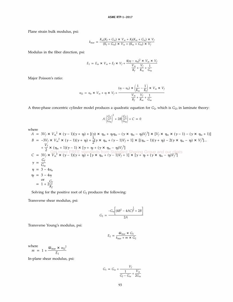
ASME RTP-1–2017
Plane strain bulk modulus, psi:
kstar pKm(Kf + Gm) � Vm + Kf(Km + Gm) � Vf
(Kf + Gm) � Vm + (Km + Gm) � Vf
Modulus in the fiber direction, psi:
E1 p Em � Vm + Ef � Vf +4(�f − �m)2 � Vm � Vf
Vm
Kf+
Vf
Km+
1Gm
Major Poisson’s ratio:
�12 p �m � Vm + �f � Vf +(�f − �m) � � 1
Km−
1Kf� � Vm � Vf
Vm
Kf+
Vf
Km+
1Gm
A three-phase concentric cylinder model produces a quadratic equation for G2, which is G23 in laminate theory:
A �G2
Gm�2
+ 2B�G2
Gm� + C p 0
whereA p 3Vf � Vm
2 � (� − 1)(� + �f) + [(�) � �m + �f�m − (� � �m − �f)Vf3] � [Vf � �m � (� − 1) − (� � �m + 1)]
B p −3Vf � Vm2 � (� − 1)(� + �f) +
12[� � �m + (� − 1)Vf + 1] � [(�m − 1)(� + �f) − 2(� � �m − �f) � Vf
3]...
+Vf
2� (�m + 1)(� − 1) � [� + �f + (� � �m − �f)Vf
3]
C p 3Vf � Vm2 � (� − 1)(� + �f) + [� � �m + (� − 1)Vf + 1] � [� + �f + (� � �m − �f)Vf
3]
� pGf
Gm
� p 3 − 4�m
�f p 3 − 4�f
orp 1 + 2
Gf
Kf
Solving for the positive root of G2 produces the following:
Transverse shear modulus, psi:
G2 p
−Gm�(4B2 − 4AC)12 + 2B�
2A
Transverse Young’s modulus, psi:
E2 p4kstar � G2
kstar + m � G2
wherem p 1 +
4kstar � �122
E1
In-plane shear modulus, psi:
G1 p Gm +Vf
1Gf − Gm
+Vm
2Gm
93
Get more FREE standards from Standard Sharing Group and our chats

ASME RTP-1–2017
Note that G1 is also referred to as G12 in laminate theory.
Transverse Poisson’s ratio:
�23 pkstar − m � G2
kstar + m � G2
Modulus of elasticity in normal direction, psi:
E33 p E22
Minor Poisson’s ratio:
�21 p E2 ��12
E1
M3-310 Micromechanics of Unidirectional Fiber Composites
The following example shows the application of the basic equations for the micromechanics of a unidirectionallamina with the properties of the fibers and resin shown in para. M3-200: The notation for kstar is used in theHalpin–Tsai equations, and KT is used in the MIL-HDBK-17-3F equations; they have identical values. The valuesfor Ef, Em, Gm, �f, and �m are from the equations in para. M3-200.
Plane strain bulk modulus for isotropic fibers:
Kf pEf
2(1 − �f − 2�f2)
p 7,684,426.230
Plane strain bulk modulus for isotropic matrix:
Km pEm
2(1 − �m − 2�m2)
p 4.938 � 105
Plane strain bulk modulus for the lamina, KT p kstar:
kstar pKm(Kf + Gm) � Vm + Kf(Km + Gm) � Vf
(Kf + Gm) � Vm + (Km + Gm) � Vfp 1,028,167 psi
KT p 1.0282 � 106 psi
Young’s modulus in the fiber direction:
E1 p Em � Vm + Ef � Vf +4(�f − �m)2 � Vm � Vf
Vm
Kf+
Vf
Km+
1Gm
p 5.3997 � 106 psi
Note that E1 is also referred to as E11 in laminate theory.
Poisson’s ratio for load in the fiber direction:
�12 p �m � Vm + �f � Vf +(�f − �m)� 1
Km−
1Kf� � Vm � Vf
Vm
Kf+
Vf
Km+
1Gm
p 0.2778
Transverse shear modulus:
G2 p
−Gm�(4B2 − 4AC)12 + 2B�
2Ap 3.943 � 105 psi
94

ASME RTP-1–2017
whereA p 3Vf � Vm
2 � (� − 1)(� + �f) + [(�) � �m + �f�m − (� � �m − �f) � Vf3] � [Vf�m(� − 1) − (� � �n + 1)]
B p 3Vf � Vm2 � (� − 1)(� + �f) +
12
[� � �m + (� − 1)Vf + 1] � [(�m − 1)(� + �f) − 2(� � �m − �f) � Vf3] ...
+Vf
2� (�m + 1)(� − 1) � [� + �f + (� � �m − �f)Vf
3]
C p 3Vf � Vm2 � (� − 1)(� + �f) + [� � �m + (� − 1)Vf + 1] � [� + �f + (� � �m − �f)Vf
3]
� pGf
Gm
�f p 3 − 4�f p 2.1200or
p 1 + 2Gf
Kfp 2.1200
�m p 3 − 4�m
Transverse to the fiber direction Young’s modulus:
E2 p4KT � G2
KT + mG2p 1.1216 � 106 psi
wherem p 1 +
4KT � �122
E1E1 p 5.3997 � 106
�12 p 0.2778
In-plane shear modulus:
G1 p Gm +Vf
1Gf − Gm
+Vm
2Gm
p 4.025 � 105 psi
Poisson’s ratios:
�21 p �12 �E2
E1p 0.0577
�23 pE2
2G2− 1 p 0.4225
or
pkstar − mG2
kstar + mG2p 0.4225
The properties of the lamina that involve through-the-thickness properties are not required for the CLT analysesbut are included for information only. Note that calculation of G23 is needed for calculating E2.
M3-320 Micromechanics of Randomly Distributed Fiber-Reinforced Composites
For random-reinforced lamina, the fictitious properties for a continuous, unidirectional lamina with the thicknessand weight of reinforcement are calculated as in para. M3-310, and the average properties are determined byintegrating over all directions from 0 deg to 180 deg. It is assumed that the lengths of the random strands exceedthe critical fiber length (approximately 0.40 in. with 400-ksi strength in the fiber) and exceed 200-psi shear strengthat the fiber–resin interface.
The average material properties of a random 1.5 oz/ft2 chopped strand mat (CSM) material can be defined asfollows:
Reduced stiffness matrix rotated:
QCSM p1�
0T -1QT-Td�
95
Get more FREE standards from Standard Sharing Group and our chats

ASME RTP-1–2017
Inverse transformation matrix:
rT−1 p �m2 n2 2mn
n2 m2 −2mn
−mn mn m2−n2 �Transpose of the inverse of the transformation matrix:
T−T p �m2 n2 −mn
n2 m2 mn
2mn −2mn m2 − n2�These matrix equations can be expanded to yield the following:
Q11CSM p1��
0 �q11 � cos (�)4 + 2(q12 + 2q66) � sin (�)2 � cos (�)2 + q22 � sin (�)4�d��Q12CSM p
1��
0 �(q11 + q22 − 4q66) � sin (�)2 � cos (�)2 + q12 � �sin (�)4 + cos (�)4��d��Q66CSM p
1��
0 �(q11 + q22 − 2q12) � sin (�)2 � cos (�)2 + q66 � �cos (�)2 − sin (�)2�2
�d��where the stiffnesses of the CSM are as follows:
q11 pE1
1 − �12 � �21
q12 p�12 � E2
1 − �12 � �21
q22 pE2
1 − �12 � �21
q66 p G12
These equations are integrated and reduce to the following:
Q11CSM p38
� q11 +14
� q12 +12
� q66 +38
� q22
Q12CSM p18
� q11 +18
� q22 −12
� q66 +34
� q12
Q66CSM p18
� q11 +18
� q22 −14
� q12 +12
� q66
By definition, the properties of an isotropic material (E, G, and �) are as follows:
Q11CSM pE
1 − �2
Q12CSM p�E
1 − �2
Q66CSM p G
96
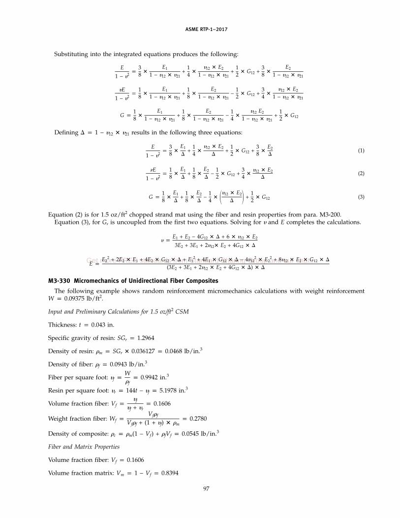
ASME RTP-1–2017
Substituting into the integrated equations produces the following:
E
1 − �2p
38
�E1
1 − �12 � �21+
14
��12 � E2
1 − �12 � �21+
12
� G12 +38
�E2
1 − �12 � �21
�E
1 − �2p
18
�E1
1 − �12 � �21+
18
�E2
1 − �12 � �21−
12
� G12 +34
��12 � E2
1 − �12 � �21
G p18
�E1
1 − �12 � �21+
18
�E2
1 − �12 � �21−
14
��12 E2
1 − �12 � �21+
12
� G12
Defining p 1 − �12 � �21 results in the following three equations:
E
1 − �2p
38
�E1
+
14
��12 � E2
+
12
� G12 +38
�E2
(1)
�E
1 − �2p
18
�E1
+
18
�E2
−
12
� G12 +34
��12 � E2
(2)
G p18
�E1
+
18
�E2
−
14
� ��12 � E2
� +12
� G12 (3)
Equation (2) is for 1.5 oz/ft2 chopped strand mat using the fiber and resin properties from para. M3-200.Equation (3), for G, is uncoupled from the first two equations. Solving for � and E completes the calculations.
� pE1 + E2 − 4G12 � + 6 � �12 � E2
3E2 + 3E1 + 2�12� E2 + 4G12 �
E pE2
2 + 2E2 � E1 + 4E2 � G12 � + E12 + 4E1 � G12 � − 4�12
2 � E22 + 8�12 � E2 � G12 �
(3E2 + 3E1 + 2�12 � E2 + 4G12 � ) �
M3-330 Micromechanics of Unidirectional Fiber Composites
The following example shows random reinforcement micromechanics calculations with weight reinforcementW p 0.09375 lb/ft2.
Input and Preliminary Calculations for 1.5 oz/ft2 CSM
Thickness: t p 0.043 in.
Specific gravity of resin: SGr p 1.2964
Density of resin: �m p SGr � 0.036127 p 0.0468 lb/in.3
Density of fiber: �f p 0.0943 lb/in.3
Fiber per square foot: �f pW�f
p 0.9942 in.3
Resin per square foot: �r p 144t − �f p 5.1978 in.3
Volume fraction fiber: Vf p�f
�f + �rp 0.1606
Weight fraction fiber: Wf pVf�f
Vf�f + (1 + �f) � �mp 0.2780
Density of composite: �c p �m(1 − Vf) + �fVf p 0.0545 lb/in.3
Fiber and Matrix Properties
Volume fraction fiber: Vf p 0.1606
Volume fraction matrix: Vm p 1 − Vf p 0.8394
97
Get more FREE standards from Standard Sharing Group and our chats

ASME RTP-1–2017
Modulus of matrix: Em p 400,000 psi
Modulus of fiber: Ef p 10.5 � 106 psi
Poisson’s ratio of fiber: �f p 0.22
Poisson’s ratio of matrix: �m p 0.35
Shear modulus of matrix (assumed isotropic): Gm pEm
2(1 + �m)p 1.481 � 105 psi
Shear modulus of fiber (assumed isotropic): Gf pEf
2(1 + �f)p 4.303 � 106 psi
Micromechanics for a unidirectional composite based on the random reinforcement properties given above areas follows:
Plane strain bulk modulus for isotropic fibers:
Kf pEf
2(1 − �f − 2�f2)
p 7,684,426.230
Plane strain bulk modulus for isotropic matrix:
Km pEm
2(1 − �m − 2�m2)
p 4.938 � 105
Plane strain bulk modulus for the lamina:
KT p kstar pKm(Kf + Gm) � Vm + Kf(Km + Gm) � Vf
(Kf + Gm)Vm + (Km + Gm)Vfp 604,811 psi
Young’s modulus in the fiber direction:
E1 p Em � Vm + Ef � Vf +4(�f − �m)2 � Vm � Vf
Vm
Kf+
Vf
Km+
1Gm
p 2.0229 � 106 psi
Poisson’s ratio for load in the fiber direction:
�12 p �m � Vm + �f � Vf +(�f − �m)� 1
Km−
1Kf� � Vm � Vf
Vm
Kf+
Vf
Km+
1Gm
p 0.3245
Transverse shear modulus:
G2 p
−Gm�(4B2 − 4AC)12 + 2B�
2Ap 1.922 � 105 psi
98

ASME RTP-1–2017
whereA p 3VfVm
2 � (� − 1)(� + �f) + [(�) � �m + �f�m − (� � �m − �f)Vf3] � [Vf�m � (� − 1) − (� � �m + 1)]
B p 3Vf � Vm2 � (� − 1)(� + �f) +
12
[� � �m + (� − 1) � Vf + 1] � [(�m − 1)(� + �f) − 2(� � �m − �f)
� Vf3] ... +
Vf
2� (�m + 1)(� − 1) � [� + �f + (� � �m − �f)Vf
3]
C p 3Vf � Vm2 � (� − 1)(� + �f) + [� � �m + (� − 1) � Vf + 1] � [� + �f + (� � �m − �f) � Vf
3]
� pGf
Gm
�f p 3 − 4�f p 2.1200or
p 1 + 2Gf
Kfp 2.1200
�m p 3 − 4�m
Transverse Young’s modulus:
E2 p4KT � G2
KT + mG2p 566,271 psi
wherem p 1 +
4KT � �122
E1E1 p 2.0229 � 106
�12 p 0.3245
Note that E2 is also referred to as E22 in laminate theory.
Plane strain bulk modulus for the lamina:
kstar p Km +Vf
1Kf − Km
+Vm
Km + Gm
p 604,811 psi
In-plane shear modulus:
G1 p Gm +Vf
1Gf − Gm
+Vm
2Gm
p 2.004 � 105 psi
Poisson’s ratios:
�21 p �12 �E2
E1p 0.0908
�23 pE2
2G2− 1 p 0.4729
or
pkstar − mG2
kstar + mG2p 0.4729
Micromechanics of random composites that are isotropic in-plane for the CSM material are as follows:
Young’s modulus:
E p
E112 + 4E11 � G12 � + 2E11 � E22 + 8�12 � E22
� G12 � − 4�122 � E22
2 + 4E22 � G12 � + E222
(3E11 + 2�12 � E22 + 3E22 + 4G12 � )p 1,025,263 psi
99
Get more FREE standards from Standard Sharing Group and our chats

ASME RTP-1–2017
whereE11 p E1E22 p E2G12 p G1
p 1 − �12 � �21 p 0.9705
In-plane shear modulus:
G pE11 − 2�12 � E22 + E22 + 4G12 �
8p 3.863 � 105 psi
In-plane Poisson’s ratio:
� pE11 + 6�12 � E22 + E22 − 4G12 �
3E11 + 2�12 � E22 + 3E22 + 4G12 � p 0.327 psi
The predicted properties of the lamina that involve through-the-thickness properties are not required for the CLTanalyses but are included for information only.
M3-400 THE CLT ANALYSIS PROCEDURE
The use of the CLT analysis equations do not require any sophisticated or complex mathematical calculations,but the enormity of the arithmetic for most laminates generally requires using a computer program for speed andaccuracy. There are a number of commercial programs available.
Other valid statements of lamination analysis may be used in place of the equations herein, but it is the responsibilityof the registered engineer to show that they are mathematically and physically consistent with the equations herein.
The basic constitutive equations for laminate theory are shown in the matrix below.
�Nx
Ny
Nxy
Mx
My
Mxy� p �
A11 A12 A16 B11 B12 B16
A21 A22 A26 B21 B22 B26
A61 A62 A66 B61 B62 B66
B11 B12 B16 D11 D12 D16
B21 B22 B26 D21 D22 D26
B61 B62 B66 D61 D62 D66� � �
�xo
�yo
�xyo
�x
�y
�xy�
Nx, N y, and Nxy are the force resultants (lb/in.). Mx, M y, and Mxy are the moment resultants (lb/in.). �xo, �yo, and�xyo are the midplane strains, and �x, � y, and �xy are the curvatures.
Explicit expansion of the above matrix:
�Nx
Ny
Nxy
Mx
My
Mxy� p�
A11 � �xo + A12 � �yo + A16 � �xyo + B11 � �x + B12 � �y + B16 � �xy
A21 � �xo + A22 � �yo + A26 � �xyo + B21 � �x + B22 � �y + B26 � �xy
A61 � �xo + A62 � �yo + A66 � �xyo + B61 � �x + B62 � �y + B66 � �xy
B11 � �xo + B12 � �yo + B16 � �xyo + D11 � �x + D12 � �y + D16 � �xy
B21 � �xo + B22 � �yo + B26 � �xyo + D21 � �x + D22 � �y + D26 � �xy
B61 � �xo + B62 � �yo + B66 � �xyo + D61 � �x + D62 � �y + D66 � �xy�
where
Aij p �n
kp1�Qbarijk
[(hk) − (hk − 1)]�100

ASME RTP-1–2017
Bij p12�
n
kp1�Qbarijk
[(hk)2 − (hk − 1)2]�
Dij p13 �
n
kp1�Qbarijk
[(hk)3 − (hk − 1)3]�hk p the vectorial distance from the geometric reference midplane of the laminate (defined as z p 0) to the
upper surface of the nth lamina. The neutral axes in the x and y directions may be different from themidplane, depending on the laminate sequence. Any dimension below the midplane is negative, and anydimension above the midplane is positive. h0 is then the distance from the midplane to the bottom of thelaminate and is negative (see Fig. M3-3).
i, j p 1, 2, 6n p total number of plies
The Qbar equations are as follows:
Qbar11 p Q11 � m4 + Q22 � n4 + 2(Q12 + 2Q66) � m2 � n2
Qbar22 p Q11 � n4 + Q22 � m4 + (Q12 + 2Q66) � 2m2 � n2
Qbar12 p (Q11 + Q22 − 4Q66) � m2 � n2 + Q12(m4 + n4)
Qbar16 p −m � n3 � Q22 + m3 � n � Q11 − mn(m2 − n2)(2Q66 + Q12)
Qbar26 p −m � n3 � Q11 + m3 � n � Q22 − mn(m2 − n2)(2Q66 + Q12)
Qbar66 p (Q11 + Q22 − 2Q12) � m2 � n2 + Q66(m2 − n2)2
wherem p cosinen p sine of the angle between material and structural axes per Fig. M3-4
Q11 pE1
Q12 p Q21 p
�12 � E2
p
�21 � E1
Q22 pE2
Q66 p G1
p 1 − �12 � �21
E1, E2, G12, and G21 are from test data or the micromechanics calculations performed above in para. M3-300.Typically, the force and moment resultants are known, and it is necessary to invert the 6 � 6 ABD matrix in the
first matrix to solve for the midplane strains and curvatures.The compliance equations are shown in the matrix below.
��xo
�yo
�xyo
�x
�y
�xy� p �
S11 S12 S13 S14 S15 S16
S21 S22 S23 S24 S25 S26
S31 S32 S33 S34 S35 S36
S41 S42 S43 S44 S45 S46
S51 S52 S53 S54 S55 S56
S61 S62 S63 S64 S65 S66� � �
Nx
Ny
Nxy
Mx
My
Mxy�
101
Get more FREE standards from Standard Sharing Group and our chats
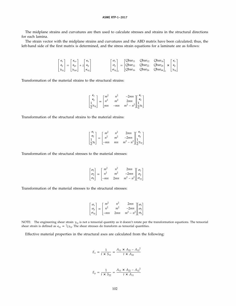
ASME RTP-1–2017
The midplane strains and curvatures are then used to calculate stresses and strains in the structural directionsfor each lamina.
The strain vector with the midplane strains and curvatures and the ABD matrix have been calculated; thus, theleft-hand side of the first matrix is determined, and the stress strain equations for a laminate are as follows:
��x
�y
�xy� p �
�xo
�yo
�xyo� + z�
�x
�y
�xy� �
x
y
xy�
k
p �Qbar11 Qbar12 Qbar16
Qbar12 Qbar22 Qbar26
Qbar16 Qbar26 Qbar66�
k
� ��x
�y
�xy�
Transformation of the material strains to the structural strains:
��x
�y
12�xy
� p �m2 n2 −2mnn2 m2 2mnmn −mn m2 − n2��
�1
�2
12�6�
Transformation of the structural strains to the material strains:
��1
�2
12�6� p �
m2 n2 2mnn2 m2 −2mn
−mn mn m2 − n2���x
�y
12�xy
�Transformation of the structural stresses to the material stresses:
� 1
2
6� p �
m2 n2 2mnn2 m2 −2mn
−mn 2mn m2 − n2�� x
y
xy�
Transformation of the material stresses to the structural stresses:
� x
y
xy� p �
m2 n2 2mnn2 m2 −2mn
−mn 2mn m2 − n2�� 1
2
6�
NOTE: The engineering shear strain �xy is not a tensorial quantity as it doesn’t rotate per the transformation equations. The tensorialshear strain is defined as �xy p 1⁄2�xy. The shear stresses do transform as tensorial quantities.
Effective material properties in the structural axes are calculated from the following:
Ex p1
t � S11p
A11 � A22 − A122
t � A22
Ey p1
t � S22p
A11 � A22 − A122
t � A11
102

ASME RTP-1–2017
Gxy p1
t � S66p
A66
t
�xy pS12
S22p
A12
A22
where the Sij terms are from the compliance matrix, the Aij terms are from the stiffness matrix, and t is the totalthickness of the laminate.
NOTE: These are only valid for balanced and symmetric laminates; all the Bij terms are 0, and there is no coupling of extensional andbending loads.
M3-500 THE QUADRATIC INTERACTION CRITERION
M3-510 Notation and Equations
In general, a plate lamina has five independent uniaxial ultimate strengths: tensile and compressive strengths inthe principal direction of greater strength, tensile and compressive strengths in the direction of lesser strength, andshear strength with respect to a pure shear stress in the principal directions. Type I laminates are treated as isotropicherein, so any direction can be considered as a principal direction. In Type II, laminates are modeled as twoorthogonal plies.
For Type X laminates, the principal direction of greater strength is aligned with continuous roving, and theprincipal direction of lesser strength is perpendicular to the roving. Further, the five strength values may be unequal.The quadratic interaction criterion defines the interactions between the five strengths in cases when more than onecomponent of stress is applied to the lamina, and it defines allowable stress states in terms of the strengths.
The criteria in para. 3B-500 are applied to each lamina separately, and if one or more lamina fail the criteria, thecorresponding load on the vessel is not allowed. The prediction of resin failure does not constitute failure as theremay be transverse fibers in that load direction to protect in any further deformation. Advanced techniques, suchas progressive failure analyses, are allowed if performed by the Professional Engineer with the caveat that anyresin failure in the corrosion barrier may likely lead to premature failure of the vessel.
The strength ratio is the ratio of the stress capacity to a calculated stress for a particular layer. The allowablestress ratios are given in para. 3B-500. This strength theory defines a failure envelope for combined stresses actingconcurrently. The Tsai–Wu version of stress ratios are calculated using the quadratic interaction equation shownbelow.
R2(Fxx � x2 + 2Fxy � x � y + Fyy � y
2 + Fss � s)2 + R(Fx � x + Fy � y) − 1 p 0
The strength ratio for each lamina is then given by the following:
R p−H ± �H2 + 4G
2G
whereG p Fxx � x
2 + 2Fxy � x � y + Fyy � y2 + Fss � s
2
H p Fx � x + Fy � y
The strength coefficients are calculated based on the tested strengths of each lamina or the strain limits givenbelow:
Fss p1
S2
Fx p1X
−1Xc
Fxx p1
X � Xc
103
Get more FREE standards from Standard Sharing Group and our chats

ASME RTP-1–2017
Fxy p12�Fxx � Fyy
Fy p1Y
−1Yc
Fyy p1
Y � Yc
NOTE: The Fxy term is a biaxial term and is assumed to be equal to the equation given above.
whereS p the ultimate in-plane shear strengthX p the ultimate tensile strength in the fiber direction
Xc p the ultimate compressive strength in the fiber directionY p the ultimate tensile strength transverse to the fiber direction
Yc p the ultimate compressive strength transverse to the fiber direction
The layer strengths may be determined from test data for each lamina or may be calculated from the strain limitsbelow.
S p �xy � Gxy
X p �xt � Ex
Xc p �xc � Ex
Y p �yt � Ey
Yc p �yc � Ey
where Ex in the fiber direction, Ey transverse to the fiber direction, and Gxy in-plane are the elastic moduli that aredetermined by testing or the micromechanics equations in para. M3-300. It is assumed that the tensile and compressivemoduli are equal.
The allowable strain limits can be measured from testing, or the following strain limits may be used (these areunchanged from ASME RTP-1–2007):
Layer Type Random Fiber Oriented Fiber
�xt 0.0150 0.0200�xc 0.0200 0.0120�yt 0.0150 0.0015�yc 0.0200 0.0080�xy 0.0268 0.0268
Caution should be used where the resin strain-to-failure properties at the worst-case design temperature are lessthan the strains listed above.
If the Fxy term is set to 0, which usually has a minimal effect on the results, the fiber- and matrix-dominatedstrengths become uncoupled and produce the following equations:
Fiber failure:
R2 � Fxx � x2 + R � Fx � x − 1 p 0
Matrix failure:
R2(Fyy � y2 + Fss � s2) + R � Fy � y − 1 p 0
This is referred to in the literature as the Hahn, Erikson, and Tsai failure theory.
M3-520 Calculation of Layer Strains and Stresses
The stresses and strains are calculated per the procedures in para. M3-400.
104
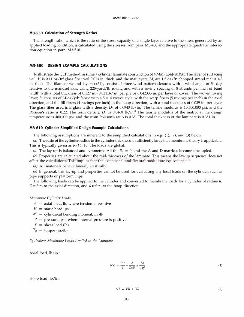
ASME RTP-1–2017
M3-530 Calculation of Strength Ratios
The strength ratio, which is the ratio of the stress capacity of a single layer relative to the stress generated by anapplied loading condition, is calculated using the stresses from para. M3-400 and the appropriate quadratic interac-tion equation in para. M3-510.
M3-600 DESIGN EXAMPLE CALCULATIONS
To illustrate the CLT method, assume a cylinder laminate construction of VMM (±54)3 MRM. The layer of surfacingveil, V, is 0.11 oz/ft2 glass fiber veil 0.013 in. thick, and the mat layers, M, are 1.5 oz/ft2 chopped strand mat 0.043in. thick. The filament wound layers (±54)3 consist of three wind pattern closures with a wind angle of 54 degrelative to the mandrel axis, using 225-yard/lb roving and with a roving spacing of 8 strands per inch of bandwidth with a total thickness of 0.127 in. (0.021167 in. per ply or 0.042333 in. per layer or cover). The woven rovinglayer, R, consists of 24-oz/yd2 fabric with a 5 � 4 weave style, with the warp fibers (5 rovings per inch) in the axialdirection, and the fill fibers (4 rovings per inch) in the hoop direction, with a total thickness of 0.039 in. per layer.The glass fiber used is E glass with a density, Df, of 0.0943 lb/in.3 The tensile modulus is 10,500,000 psi, and thePoisson’s ratio is 0.22. The resin density, Dr, is 0.0468 lb/in.3 The tensile modulus of the matrix at the designtemperature is 400,000 psi, and the resin Poisson’s ratio is 0.35. The total thickness of the laminate is 0.351 in.
M3-610 Cylinder Simplified Design Example Calculations
The following assumptions are inherent to the simplified calculations in eqs. (1), (2), and (3) below.(a) The ratio of the cylinder radius to the cylinder thickness is sufficiently large that membrane theory is applicable.
This is typically given as R/t > 10. The loads are global.(b) The lay-up is balanced and symmetric. All the Bij p 0, and the A and D matrices become uncoupled.(c) Properties are calculated about the mid-thickness of the laminate. This means the lay-up sequence does not
affect the calculations. This implies that the extensional and flexural moduli are equivalent.(d) All materials behave linearly elastically.(e) In general, this lay-up and properties cannot be used for evaluating any local loads on the cylinder, such as
pipe supports or platform clips.The following loads can be applied to the cylinder and converted to membrane loads for a cylinder of radius R;
Z refers to the axial direction, and � refers to the hoop direction:
Membrane Cylinder LoadsA p axial load, lb, where tension is positiveH p static head, psiM p cylindrical bending moment, in.-lbP p pressure, psi, where internal pressure is positiveS p shear load (lb)
T0 p torque (in.-lb)
Equivalent Membrane Loads Applied to the Laminate
Axial load, lb/in.:
NZ pPR2
+A
2R±
M
R2(1)
Hoop load, lb/in.:
NT p PR + HR (2)
105
Get more FREE standards from Standard Sharing Group and our chats

ASME RTP-1–2017
Table M3-1 Properties for Materials in the Design Example
Ply Thickness, Number Thickness, in.Material E11 E22 G12 �12 in. of Plies [Note (1)] �, deg
c-veil 5.4920E+05 5.4920E+05 2.0487E+05 0.3404 0.0130 1 0.0130 01.5-oz Mat 1.0253E+06 1.0253E+06 3.8633E+05 0.3269 0.0430 4 0.1720 024-oz Weave, 3.6429E+06 7.6410E+05 2.7484E+05 0.3011 0.0170 1 0.0170 90
unidirectionalRoving 5/4 Weave, 3.5323E+06 7.4761E+05 2.6877E+05 0.3027 0.0220 1 0.0220 0
unidirectionalFilament wound 5.3977E+06 1.1216E+06 4.0245E+05 0.2778 0.0212 6 0.1270 54
roving
NOTE:(1) Total thickness for all layers in the design example laminate p 0.351 in.
In-plane shear load, lb/in.:
NZT pS
R+
To
R2(3)
M3-611 Lamina Mechanical Properties Using Micromechanics. Using the fiber and matrix properties and thefiber orientations, the corresponding tensile modulus in the x and y directions, in-plane shear modulus, and Poisson’sratios are obtained from the appropriate equations in paras. M3-310 and M3-320 for all the layers in the laminate.This results in the properties for each of the materials given in the design example, as shown in Table M3-1.
The A matrix and A inverse matrices are then calculated using the following:(a) A Matrix
�5.0764E+05 2.4249E+05 0.0000E+002.4249E+05 6.6568E+05 0.0000E+000.0000E+00 0.0000E+00 2.5672E+05�
where the determinent of matrix A is 7.166E+16.(b) A Inverse Matrix
�2.385E−06 −8.688E−07 0
−8.688E−07 1.819E−06 00 0 3.895E−06�
The effective mechanical and physical properties for use in Subpart 3A design are as follows:
Effective MechanicalProperties Values
E-Z (psi) 1.1946E+06E-� (psi) 1.5665E+06G-Z, � (psi) 7.3141E+05�-�Z 0.4777�-Z� 0.3643
Effective PhysicalProperties Values
Density, lb/in.3 0.0608Glass vol. fraction 0.2941Glass weight fraction 0.4564
M3-620 Advanced Design Example Calculations
This CLT calculation includes the effects of the unbalanced laminate sequence. The hoop and axial extensionalmoduli are influenced by the coupling effects in the Bij matrix. The hoop and axial moduli in flexure are based onbending about the neutral axes in the x (axial) and y (hoop) directions.
The reductions of several or more plies to three plies that represents the actual in-plane and bending responsescan also be referred to as smeared properties or “macros.”
106

ASME RTP-1–2017
The woven roving layer is modeled as three unidirectional layers oriented at 0 deg and 90 deg. The thickness ofthese layers is proportioned with respect to the weave style (5/9 for axial and 4/9 for hoop). However, the distancez between the reference plane and the centroid of this layer is taken to the center of the total layer to prevent anunbalanced calculation of the flexural properties. The neutral axes in bending in the x and y direction are equalfor this macro. Paragraph M3-640 demonstrates the macro formulation.
The filament wound layers are also input into the CLT equations as a balanced and symmetric laminate withthree layers, and the resultant effective properties are then used in the subsequent CLT analysis as these layerswith the calculated “smeared” properties. The neutral axes in bending in the x and y directions are equal for thismacro.
The lamina input (developed from the micromechanics in paras. M3-310 and M3-320) for the laminate theorycalculations are shown in Table M3-2.
Table M3-2 Lamina Input for CLT Calculations
Thickness,t, in.
Material E1, psi E2, psi �12 G12, psi [Note (1)] �, deg
c-veil 549,204 549,204 0.3404 204,873 0.01300 . . .1.5-oz. Mat 1,025,263 1,025,263 0.3269 386,332 0.04300 . . .1.5-oz. Mat 1,025,263 1,025,263 0.3269 386,332 0.04300 . . .Filament wound 5,399,768 1,121,666 0.2778 402,462 0.03175 54.00Filament wound 5,399,768 1,121,666 0.2778 402,462 0.06350 −54.00Filament wound 5,399,768 1,121,666 0.2778 402,462 0.03175 54.001.5-oz. Mat 1,025,263 1,025,263 0.3269 386,332 0.04300 . . .24-oz Woven roving, axial 3,532,357 747,611 0.3027 268,767 0.01100 . . .24-oz Woven roving, hoop 3,642,856 764,104 0.3011 274,843 0.01700 90.0024-oz Woven roving, axial 3,532,357 747,611 0.3027 268,767 0.01100 . . .1.5-oz. Mat 1,025,263 1,025,263 0.3269 386,332 0.04300 . . .
NOTE:(1) Total thickness for all layers p 0.351 in.
Mid-Surface
Mechanical A B D Strain Thermal Moisture
Nx p 5.0764E+05 2.4249E+05 −1.0908E−11 −5.7198E+03 1.8098E+03 −6.8275E−13 � �xo − Nxt − Nxm
Ny p 2.4249E+05 6.6568E+05 −1.1501E−11 1.8098E+03 −2.0792E+03 −1.4816E−12 � �yo − Nyt − Nym
Nxy p −1.0908E−11 −1.1501E−11 2.5672E+05 −6.8275E−13 −1.4816E−12 1.7713E+03 � �xyo − Nxyt − Nxym
Mx p −5.7198E+03 1.8098E+03 −6.8275E−13 4.6580E+03 1.3989E+03 9.1103E+01 � �x − Mxt − Mxm
My p 1.8098E+03 −2.0792E+03 −1.4816E+12 1.3989E+03 4.7438E+03 1.7359E+02 � �y − Myt − Mym
Mxy p −6.8275E−13 −1.4816E−12 1.7713E+03 9.1103E+01 1.7359E+02 1.4606E+03 � �xy − Mxyt − Mxym
Inverse
MidplaneStrain andCurvature A B D Mechanical Thermal Moisture
�xo p 2.4638E−06 −9.1681E−07 −3.2153E−10 4.1519E−06 −2.5678E−06 4.6601E−08 � Nx + Nxt + Nxm
�yo p −9.1681E−07 1.8486E−06 5.0419E−10 −2.4047E−06 1.8718E−06 −7.3075E−08 � Ny + Nyt + Nym
�xyo p −3.2153E−10 5.0419E−10 3.9262E−08 4.4233E−08 1.6243E−07 −4.7859E−06 � Nxy + Nxyt + Nxym
�x p 4.1519E−06 −2.4047E−06 4.4233E−08 2,4309E−04 −7.4090E−05 −6.4109E−06 � Mx + Mxt + Mxm
�y p −2.5678E−06 1.8718E−06 1.6243E−07 −7.4090E−05 2.3531E−04 −2.3542E−05 � My + Myt + Mym
�xy p 4.6601E−08 −7.3075E−06 −4.7859E−06 −6.4109E−06 −2.3542E−05 6.9365E−04 � Mxy + Mxyt + Mxym
107
Get more FREE standards from Standard Sharing Group and our chats

ASME RTP-1–2017
The following are the classical laminate theory calculations for the ABD matrices from para. M3-400:The following are the calculations for the ABD matrices developed from the neutral axes in the x (axial) and y
(hoop) directions from para. M3-400:
ABD Matrix From Bending x Worksheet
507,641 242,493 0 0.000 4,542.056 0.000242,493 665,683 0 4,542.056 5,421.355 0.000
0 0 256,725 0.000 0.000 4,664.9040.000 4,542.056 0.000 4,593.56 1,470.48 91.10
4,542.056 5,421.355 0.000 1,470.48 4,781.43 173.590.000 0.000 4,663.904 91.10 173.59 1,533.11
ABD Matrix From Bending y Worksheet
501,426 208,198 0 −2,936.892 2,371.882 0208,198 569,659 0 2,371.882 0.000 0
0 0 207,210 0 0 2,222.725−2,936.892 2,371.882 0 4,616.66 1,419.54 02,371.882 0.000 0 1,419.54 4,596.93 0
0 0 2,222.725 0 0 1,409.51
The following are the effective material properties for the laminate:
Material Properties Values
Ex 1,186,552 psiEy 1,549,065 psi�xy 0.3624�yx 0.4904Gxy 704,682 psiEx flexural 1,141,529 psiEy flexural 1,179,272 psi�xy flexural 0.3048�yx flexural 0.3149Dx flexural 4550 lb-in.Dy flexural 4701 lb-in.Esx extensional 506,507 lb-in.Esy extensional 661,254 lb-in.Mid-thickness 0.1755 in.Neutral axis x 0.1642 in.Neutral axis y 0.1724 in.
where the following assumptions have been made:(a) Extension Ex and �xy and flexural Ex and �xy are calculated based on the neutral x axis, such that an extensional
load Nx produces no curvature in the x direction, and an Mx bending load produces no x direction extension.(b) Extensional Ey and �yx and flexural Ey and �yx are calculated based on the neutral y axis, such that an extensional
load Ny produces no curvature in the y direction, and an My bending load produces no y-direction extension.(c) In-plane Gxy is assumed to be the average of the Gxy calculated using the x and y neutral axes.
NOTES:(1) These are one-dimensional values, and the full ABD matrix needs to be used for laminates that have Bij terms present to determine
the actual response of the laminate because of the additional coupling terms.(2) These predicted material properties using the advanced CLT are within a few percent of those calculated using the simplified design
example in para. M3-610 for the Ex (Ez) and Ey (E�) values.
M3-630 Stresses, Strains, and Strength Ratios Example
Using the simplified design calculation example in para. M3-610 and assuming a biaxial pressure of 10 psi andan inside diameter of 120 in., the stresses, strains, and strength ratios are calculated; results are shown Table M3-3.
A comparison of the calculated R values shows that there is close agreement between the four strength theories.
M3-640 Macro or Smeared Property Formulation
Resin crazing is allowed in the laminate, except for the liner materials. Filament wound, unidirectional, andwoven roving materials can produce an artificially low R value due to loads transverse to the fiber directions. Then,
108

ASME RTP-1–2017
Table M3-3 Stresses, Strains, and Strength Ratios
24-oz Woven, Roving 5/4 Filament WoundStrains c-veil 1.5-oz Mat Hoop Weave, Axial Roving
Material axes�1 0.00019 0.00019 0.00019 0.00019 0.00019�2 0.00083 0.00083 0.00083 0.00083 0.00083�12 0.00000 0.00000 0.00000 0.00000 0.00000
Structural axes�x 0.00019 0.00019 0.00019 0.00019 0.00061�y 0.00083 0.00083 0.00083 0.00083 0.00041�xy 0.00000 0.00000 0.00000 0.00000 0.00061
Roving 5/424-oz Woven, Weave, Filament Wound
Stresses c-veil 1.5-oz Mat Unidirectional Unidirectional Roving
Material axes 1 296.23 534.65 346.08 891.23 1,407.05 2 556.98 1,026.36 3,129.91 678.04 2,740.91 12 0.00 0.00 0.00 0.00 1,264.37
Structural axes x 296.23 534.65 3,129.91 891.23 3,482.56 y 556.98 1,026.36 346.08 678.04 665.40 xy 0.00 0.00 0.00 0.00 243.58
Roving 5/424-oz Woven, Weave, Filament Wound
Strength Calculations c-veil 1.5-oz Mat Unidirectional Unidirectional Roving
XT, psi 8,238 15,379 72,857 70,647 107,994XC, psi 10,984 20,505 43,714 42,388 64,796YT, psi 8,238 15,379 1,146 1,121 1,682YC, psi 10,984 20,505 6,113 5,981 8,973S, psi 5,491 10,354 7,366 7,203 10,786
Fxx 1.1051E−08 3.1711E−09 3.1398E−10 3.3394E−10 1.4291E−10Fxy −5.5256E−09 −1.5855E−09 −3.3472E−09 −3.5281E−09 −1.5383E−09Fyy 1.1051E−08 3.1711E−09 1.4273E−07 1.4910E−07 6.6238E−08Fss 3.3171E−08 9.3285E−09 1.8431E−08 1.9274E−08 8.5960E−09Fx 3.0347E−05 1.6256E−05 −9.1503E−06 −9.4366E−06 −6.1732E−06Fy 3.0347E−05 1.6256E−05 7.0889E−04 7.2453E−04 4.8292E−04
G 2.5748E−03 2.5068E−03 1.2920E−02 6.4547E−02 2.4441E−02H 2.5892E−02 2.5376E−02 2.1670E−01 4.8285E−01 2.9984E−01
24-oz Woven, Roving 5/4Strength Ratios c-veil 1.5-oz Mat Hoop Weave, Axial Roving
R, Compcyl 15.31 15.54 3.77 1.69 2.73
R, Advanced CLT 14.59 14.85 3.69 1.74 2.72
R, Hahn, Erikson,Hahn Compcyl
R fiber 27.81 28.76 23.28 79.27 31.01R matrix 14.79 14.98 3.31 1.65 2.52
R, Trilam 16.71 15.95 4.04 1.73 2.85
load transverse to the fiber direction may be protected due to the adjacent transverse fibers. The strength of themacro is not compromised, provided there is no fiber failure.
This example is based on the woven roving with properties as calculated in para. M3-310 and used in the designexample.
The woven roving layer is modeled as a balanced and symmetric three-ply laminate as shown in Table M3-4.All the effective elastic properties and strengths per strain limits of this three-ply model can be determined asshown in this Table.
109
Get more FREE standards from Standard Sharing Group and our chats

AS
ME
RTP-1–2017
Table M3-4 Woven Roving Layer Modeled as a Balanced and Symmetric Three-Ply Laminate
Material Thickness,(Top to t, in.Bottom) E1 psi E2 psi �12 G12 psi [Note (1)] �, deg CTE 1 CTE 2 CME 1 CME 2 1 Tens 1 Comp 2 Tens 2 Comp Shear
24-oz Woven 3,532,357 747,611 0.302652133 268,767 0.01100 5.39276E−06 3.29634E−05 5.95445E−06 7.09872E−02 70,647 42,388 1,121 5,981 7,203roving, axial
24-oz Woven 3,642,856 764,104 0.301116966 274,843 0.01700 90 5.27421E−06 3.25132E−05 5.82259E−06 7.15867E−05 72,857 43,714 1,146 6,113 7,366roving, hoop
24-oz Woven 3,532,357 747,611 0.302652133 268,767 0.01100 5.39276E−06 3.29634E−05 5.95445E−06 7.09872E−05 70,647 42,388 1,121 5,981 7,203roving, axial
Mid-SurfaceMechanical A B D Strain Thermal Moisture
Nx p 9.2490E+04 9.0635E+03 5.5340E−15 0.0000E+00 0.0000E+00 0.0000E+00 � �xo − Nxt − Nxm
Ny p 9.0635E+03 7.9902E+04 3.0505E−12 0.0000E+00 0.0000E+00 0.0000E+00 � �yo − Nyt − Nym
Nxy p 5.5340E−15 3.0505E−12 1.0585E+04 0.0000E+00 0.0000E+00 0.0000E+00 � �xyo − Nxyt − Nxym
Mx p 0.0000E+00 0.0000E+00 0.0000E+00 1.6651E+01 1.1422E+00 1.3328E−19 � �x − Mxt − Mxm
My p 0.0000E+00 0.0000E+00 0.0000E+00 1.1422E+00 4.9769E+00 7.3465E−17 � �y − Myt − Mym
Mxy p 0.0000E+00 0.0000E+00 0.0000E+00 1.3328E−19 7.3465E−17 1.3311E+00 � �xy − Mxyt − Mxym
Inverse
Mid-SurfaceStrain A B D Mechanical Thermal Moisture
�xo p 1.0934E−05 −1.2402E−06 3.5169E−22 0.0000E+00 0.0000E+00 0.0000E+00 � Nx + Nxt + Nxm
�yo p −1.2402E−06 1.2656E−05 −3.6466E−21 0.0000E+00 0.0000E+00 0.0000E+00 � Ny + Nyt + Nym
�xyo p 3.5169E−22 −3.6466E−21 9.4472E−05 0.0000E+00 0.0000E+00 0.0000E+00 � Nxy + Nxyt + Nxym
�x p 0.0000E+00 0.0000E+00 0.0000E+00 6.1018E−02 −1.4003E−02 7.6676E−19 � Mx + Mxt + Mxm
�y p 0.0000E+00 0.0000E+00 0.0000E+00 −1.4003E−02 2.0414E−01 −1.1266E−17 � My + Myt + Mym
�xy p 0.0000E+00 0.0000E+00 0.0000E+00 7.6676E−19 −1.1266E−17 7.5128E−01 � Mxy + Mxyt + Mxym
Effective Mechanical Properties (Classical) Effective Mechanical Properties[Note (1)] Effective Thermal Properties Effective Moisture Properties (Axisymmetric, Bij p 0)
Ex p 2,345,171 Ex flex p 3,315,332 CTE X p 5.198E−26 ME X p −2.676E−09 Ex p 2,345,171Ey p 2,025,990 Ey flex p 990,961 CTE Y p −5.390E−25 ME Y p 2.731E−08 Ey p 2,025,990
�xy p 0.1134 �xy flex p 0.2295 CTE XY p 1.396E−08 ME XY p −7.869E−24 �xy p 0.1134�yx p 0.0980 �yx flex p 0.0686 �yx p 0.0980Gxy p 271,415 Gxy flex p 269,270 Gxy p 271,415
NOTE:(1) Except for Ex flex, Ey flex, and �xy flex, the values are incorrect for unbalanced lay-ups.
110

ASME RTP-1–2017
The strengths for this macro are based on the strain allowables in para. M3-310 and by discounting the strengthof the transverse plies. The tensile strength in the 1 direction is the product of the strain allowable (0.020) and Ex,which is 46,903 psi. The tensile strength in the 2 direction is the product of the strain allowable (0.020) and Ey,which results in a strength of 40,520 psi. The other strengths are determined in a similar way, and the result is thefollowing:
Equivalent �12, G12,Macro Layer E11, psi E22, psi psi psi t, in. 1 Tens, psi 1 Comp, psi 2 Tens, psi 2 Comp, psi Shear, psi
24-oz Woven 2,345,171 2,025,990 0.1134 271,415 0.03900 46,903 24,312 40,520 16,208 7,274roving,smeared
The effect of this formulation is similar to a progressive failure analysis where the transverse properties areassumed to be diminished in the original model. This is a conservative approach, as there may be no resin crazingfor the design loads.
This approach also applies to unidirectional axial plies with hoop winds.
111
Get more FREE standards from Standard Sharing Group and our chats

(17)
ASME RTP-1–2017
MANDATORY APPENDIX M-4QUALITY CONTROL PROGRAM
M4-100 GENERAL
(a) The Fabricator shall have and maintain a QualityControl Program that will ensure that all of the require-ments of this Standard and any other applicable docu-ments, as agreed between the Fabricator and the User,will be met.
(b) The Fabricator shall maintain a program suitablefor the scope and detail of the work performed, and thesize and complexity of the Fabricator’s organization, andshall designate a Certified Individual (see para. 1-400).A written description of the program shall be availablefor review.
(c) A copy of the Fabricator’s Quality Control Manualshall be made available to the Inspector on request. TheFabricator’s Quality Control Manual may contain pro-prietary information and procedures. No copies of theFabricator’s Quality Control Manual shall be removedfrom the Fabricator’s premises without the Fabricator’sexpress permission. This security permission does notapply to quality control forms and checklists that maybe a portion of the Quality Control Manual and arenecessary to be used during fabrication to check thefabrication process. These quality control forms becomeattachments to the Fabricator ’s Data Report (seeTable 1-2).
M4-200 ORGANIZATION
The Quality Control Program shall include theFabricator ’s organization chart, which indicatesreporting responsibility and authority. The purpose ofthis chart is to identify and associate the various organi-zational groups with the particular function for whichthey are responsible. The organization chart showingthe relationship between management and engineering,purchasing, fabrication, inspection, and quality controlis required to reflect the actual organization. ThisStandard does not intend to encroach on the Fabricator’sright to establish and to alter whatever form of organiza-tion the Fabricator desires, as long as it is appropriateto fulfill the work within this Standard. This chart shallillustrate that the quality control function is independentof the production group and marketing group.
112
M4-300 DOCUMENTATION
(a) The Quality Control Program shall include as aminimum the documentation required by this Standard.These documents shall be organized in one place andreadily available while fabrication is in progress.
(b) The Quality Control Program shall provide forincorporation of procedures that will ensure that thelatest applicable drawings, design calculations, andspecifications are used for fabrication, inspection, andtesting.
(c) Documentation shall be retained by the Fabricatorfor a minimum of 5 yr.
M4-400 QUALITY CONTROL
The Quality Control Program shall include specificprocedures for the following:
(a) inspection of received goods, including raw mate-rials and purchased items, i.e., any materials that willbecome part of the finished vessel.
(b) in-process inspection of resin mixing, raw materialdispersion, component fabrication, and assembly proce-dures, including verification of reinforcing sequence(refer to Parts 4 and 6 of this Standard).
(c) scheduling and notification for Inspector’s holdpoints and final acceptance inspection. Refer toparas. 6-300, 1-400, 1-430, and 1-440. Typical inspectionevents are given in Tables NM7-1 and NM7-2.
(d) inspection of the finished vessel (refer to Parts 4and 6).
(e) rectifying nonconformities or imperfections thatshall be done in accordance with MandatoryAppendix M-7 and shall be recorded on forms includedin the Fabricator’s Quality Control Program. Minimumdata to be recorded shall be date of correction, specificlocation on the vessel, description of nonconformity orimperfection, method of correction, name of qualifiedLaminator or Secondary Bonder who made the correc-tion, and signature approvals for each correction inaccordance with Mandatory Appendix M-7 and theFabricator’s Quality Control Program.
(f) maintenance and calibration of all inspection andtest equipment.
(g) internal audits of the Quality Control Program.The Certified Individual shall perform the internalaudits at the frequency specified in the QC Manual. Themaximum interval between audits shall be 14 months

ASME RTP-1–2017
(although 6-month intervals are recommended). The firstaudit shall occur no more than 1 yr from the date ofissuance of the Certificate of Authorization.
(h) assurance that the RTP-1 nameplate informationmeets the requirements of the UBRS and para. 1-540.
M4-500 EXAMPLE OF A FABRICATOR’S QUALITYCONTROL PROGRAM
An example of a Fabricator’s Quality Control Programis included in Nonmandatory Appendix NM-6.
113
Get more FREE standards from Standard Sharing Group and our chats

ASME RTP-1–2017
MANDATORY APPENDIX M-5QUALIFICATION OF LAMINATORS AND SECONDARY BONDERS
M5-100 GENERAL REQUIREMENTS
(a) This Appendix specifies the rules for qualifyingpersonnel to produce laminates and/or perform second-ary bonding operations. Laminates and overlays thereof(secondary bonds) shall only be made by personnel whohave been qualified in accordance with the rules of thisAppendix.
(b) A Laminator is an individual who makes laminates.This is not to preclude assistance being provided to theLaminator by one to four assistants.
(c) A Secondary Bonder is an individual who joins andoverlays cured subassemblies of the vessel being fabri-cated. This is not to preclude assistance being providedto the Secondary Bonder by one or two assistants.
(d) The Fabricator shall maintain up-to-date recordsrelating to qualification of each Laminator andSecondary Bonder. These records will document the dateof last qualification and will include all calculations andtest or inspection reports from both internal and inde-pendent laboratory testing programs used in the processof qualification. These records are subject to review onrequest by all parties engaged in the process of procure-ment or inspection.
M5-200 RESPONSIBILITY
It is the responsibility of the Fabricator to train andqualify Laminators and Secondary Bonders.
M5-300 QUALIFICATION OF LAMINATORS
(a) Laminators may qualify their capabilities at thetime a Fabricator produces a demonstration laminatefor the purpose of shop qualification.
(b) To qualify, a Laminator must produce one Type IIdemonstration laminate (see Part 7), fabricated of anypolyester or vinyl ester resin, which upon test in accor-dance with the instructions in Part 7 fulfills the require-ments of this Standard. A Laminator QualificationReport, Table M5-1, shall be completed and signed foreach laminator qualification.
(c) All laminates made for qualification shall be iden-tified in accordance with para. 7-900.
(d) Laminators shall be requalified if inactive for6 months.
(e) The Certified Individual may require requalifica-tion of a Laminator at any time if there is cause to
114
question the Laminator’s ability to produce laminatesin accordance with the requirements of this Standard.
M5-400 QUALIFICATION OF SECONDARYBONDERS
(a) Secondary Bonders must qualify their capabilitiesin accordance with the procedures that follow:
(b) It is the responsibility of the Fabricator’s QualityControl Manager to
(1) ensure compliance with procedures as outlinedfor the preparation and machining of test samples.
(2) make or supervise the making of circumferencemeasurements.
(3) make, sign, and date a Secondary BonderQualification Report; see Table M5-2. Attached to theSecondary Bonder Qualification Report shall be copiesof a Component Data Sheet, including all items listed inTable NM6-2. Two Component Data Sheets are required,one for the pipe test piece, the second for the overlay.The Component Data Sheets shall be appropriatelyidentified.
M5-410 Making Pipe Test Pieces
(a) Three pipe test pieces shall be made by a qualifiedLaminator utilizing brightly pigmented polyester orvinyl ester resin.
(b) The resin must be one that the Fabricator has quali-fied through the production of a demonstrationlaminate.
(c) Refer to Fig. M5-1 for dimensions of pipe testpieces.
(d) The Laminator shall apply a nonpigmented, paraf-finated top coat to the pipe exterior.
(e) After lamination, application of paraffinated topcoat, and cure, the pipe test pieces must be aged at 70°Fto 80°F for at least 72 hr before the Secondary Bondermay begin to make overlays.
M5-420 Making Secondary Bond Test Assemblies
(a) The Secondary Bonder must overlay three pipetest pieces to make three secondary bond test assembliesas illustrated in Fig. M5-2.
(b) The Secondary Bonder shall prepare the pipe testpieces for overlay per para. 4-320(a). Care should betaken to maintain an even surface and constant circum-ference, avoiding removal of excess material that wouldresult in grooves, tapers, or flat spots.

ASME RTP-1–2017
Table M5-1 Laminator Qualification Report
Data by Fabricator:
Fabricator Laminator
Address Last qualification date
Lamination date
Quality Control Manager
Fabrication process Resin type
Laminate type Catalyst type
Data by Test Laboratory:
Test laboratory Test report no.
Lab technician Testing date
Specimen Specimen Specimen
Number Thickness Width Test Speed Peak Load Sx Sy Ex Ey
1
2
3
4
5
Average
Type II laminates require properties in the warp direction only.
Test laboratory representative Date(signature)
Certification:
The Laminator whose name appears above is qualified under the provisions of RTP-1, Part 7 and Mandatory Appendix M-5.
Quality Control Manager Date(signature)
Laminator Date(signature)
GENERAL NOTES:(a) This form may be reproduced and used without written permission from ASME if used for purposes other than republication.(b) Attach copies of Table NM6-2 (Component Data Sheet) and laboratory test report to this Laminator Qualification Report.
115
Get more FREE standards from Standard Sharing Group and our chats

ASME RTP-1–2017
Table M5-2 Secondary Bonder Qualification Report
Fabricator Secondary Bonder
Address Last qualification date
Secondary bonding date
Quality Control Manager Test laboratory
Qualified Laminator Lab technician
Pipe fabrication date Testing date
Data by Fabricator:
Pipe Circumferences
Specimen Number C1 C2 Ca
Ha p La − Da
Sb pP
Ca Ha(minimum allowable p 2,000 psi)
Data by Test Laboratory:
Test laboratory representative Date(signature)
Shear Collar Height Relief Bore Depth Shear Shear
Specimen Height Peak Load Strength
Number L1 L2 L3 La D1 D2 D3 Da Ha P Sb
The following certify that they have executed their responsibilities and tests in accordance with the requirements of ASME RTP-1,
para. M5-400:
Secondary Bonder Date(signature)
Quality Control Manager Date(signature)
Secondary Bonder □ is qualified □ is not qualified
GENERAL NOTES:(a) This form may be reproduced and used without written permission from ASME if used for purposes other than republication.(b) Attach copies of Table NM6-2 (Component Data Sheet) to this Secondary Bonder Qualification Report. One Component Sheet is to
apply to the pipe test piece per Fig. M5-1; the other is to apply to the overlay per Fig. M5-2. Identify each Component Data Sheetaccordingly.
116

ASME RTP-1–2017
Fig. M5-1 Pipe Test Piece
Type II laminate, 0.37 in. nominal thickness (per Table 2A-2)
CL
Approx. 3/4 in. Approx. 3/4 in.
I.D. 3 in. ± 1/64 in.
18 in. ± 1/8 in.
1 in. to 11/4 in. (typical)
Mark average circumference length in these areas [see para. M5-420(d)]
Measurement locations
Ca =
Ca
=
(c) After preparation for overlay, the circumferenceof the area to be overlayed shall be measured using ametal tape measure at the points indicated in Fig. M5-1.This must be done for each of the three pipe test piecesto be overlayed. Measurements must be made in accor-dance with para. M5-400(b)(2). Measurement accuracyshall be ±1⁄16 in. and rounded to the nearest 1⁄16 in.
(d) For each of three pipe test pieces, the two circum-ference measurements shall be recorded in theSecondary Bonder Qualification Report. Whenrecording measurements, express the values as the deci-mal equivalents of the measurements taken. Calculatethe average of the two circumference measurements andround it off to the nearest hundredth of an inch; thisvalue is Ca. The value of Ca shall be recorded in thereport and also marked in 1⁄2-in. to 3⁄4-in. size numerals,with a black indelible marker, at each end of a pipe testpiece. See Fig. M5-1 for approximate locations wherethe average circumference value, Ca, is to be marked oneach pipe test piece.
(e) The Secondary Bonder shall then overlay the threepipe test pieces, following instructions in paras. 4-320(b)through (d), so as to make secondary bond test assem-blies as shown in Fig. M5-2. Nonpigmented resin is tobe used.
M5-430 Making and Measuring Secondary Bond TestSpecimens
(a) After the overlay is cured, and cure is verified perthe instructions in para. 6-910, machine the secondarybond test assemblies to make secondary bond test speci-mens in accordance with Fig. M5-3.
117
(b) Each secondary bond test assembly makes twosecondary bond test specimens when cut on the center-line of the overlay.
(c) A minimum of five secondary bond test specimensare required to be made for testing.
(d) Machining operations may be done by theFabricator, at another firm or location, or at an indepen-dent testing laboratory.
M5-440 Testing Secondary Bond Test Specimens andCalculating Secondary Bond Shear Strength
(a) When machining is complete, five secondary bondtest specimens must be tested by an independent testinglaboratory.
(b) Prior to testing, the average engagement height ofthe shear collar must be determined for each secondarybond test specimen.
(c) Measurements and calculations to determine theaverage engagement height of the shear collar must bedone at the independent testing laboratory where thetest specimens are to be tested.
(d) To determine the average engagement height, Ha,for each test specimen, proceed as follows:
(1) Refer to Fig. M5-3.(2) Using a vernier caliper, make three measure-
ments of the shear collar height, L, at approximately120-deg intervals and record the measurements in theSecondary Bonder Qualification Report. The average ofthe three measurements, La, shall be calculated; the valueshall be rounded off to the nearest hundredth of an inch,recorded in the report, and also marked on each testspecimen in approximately the area shown in Fig. M5-3.
Get more FREE standards from Standard Sharing Group and our chats

ASME RTP-1–2017
Fig. M5-2 Secondary Bond Test Assembly
CL
Ca =
Ca
=
9 in. ± 1/8 in.
Overlay
Laminate sequence 2M, 3(MR), M, V [see paras. 4-320(b) through (d)]
Secondary Bonder to mark name and/or employee no. at both ends of secondary bond test assembly, 90 deg to Ca data.Quality Control Manager to mark a number at each end, 180 deg to Ca data. (There must be a different number at each end of each assembly.)
118

ASME RTP-1–2017
Fig. M5-3 Secondary Bond Test Specimen
L
636363
63
Top and bottom surfaces of specimen must be parallel [see Note (1)]
8 in. to 9 in.
1 in. min. 11/16 in. max
1/8 in. to 3/16 in. plunge cut [see Note (2)]
1/8 in. max. 1/32 in. min. [see Note (5)]
Ca =
Shear collar
Section A– A
Split Shear Collar and Pipe
Relief bore [see Note (4)]
D [see Note (3)]
Approximate location and general arrangement for all measurement markings to be placed on each test specimen
La =
Da =
Ha =
A
A
GENERAL NOTE: indicates machine lathe finish.
NOTES:(1) Lack of parallelism may reduce test values.(2) Plunge cut with squared nose parting tool to depth sufficient to expose pigmented laminate a full 360 deg and over total
surface of root of slot.(3) Machine back pipe 1/4 in. minimum to 5/16 in. maximum.(4) Machine away internal surface of shear collar to be outboard of pipe external surface 3/32 in. minimum, a full 360 deg.(5) Slit must extend completely through the wall of the shear collar (and pipe) and be of length sufficient to protrude fully
into the plunge cut slot.
119
Get more FREE standards from Standard Sharing Group and our chats
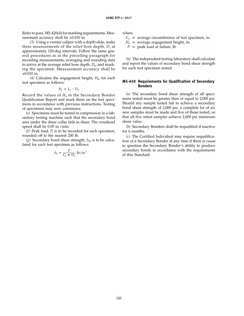
ASME RTP-1–2017
Refer to para. M5-420(d) for marking requirements. Mea-surement accuracy shall be ±0.010 in.
(3) Using a vernier caliper with a depth slide, makethree measurements of the relief bore depth, D, atapproximately 120-deg intervals. Follow the same gen-eral procedures as in the preceding paragraph forrecording measurements; averaging and rounding datato arrive at the average relief bore depth, Da; and mark-ing the specimen. Measurement accuracy shall be±0.010 in.
(4) Calculate the engagement height, Ha, for eachtest specimen as follows:
Ha p La − Da
Record the values of Ha in the Secondary BonderQualification Report and mark them on the test speci-mens in accordance with previous instructions. Testingof specimens may now commence.
(e) Specimens must be tested in compression in a lab-oratory testing machine such that the secondary bondarea under the shear collar fails in shear. The crossheadspeed shall be 0.05 in./min.
(f) Peak load, P, is to be recorded for each specimen,rounded off to the nearest 200 lb.
(g) Secondary bond shear strength, SB, is to be calcu-lated for each test specimen as follows:
SB pP
Ca � Ha, lb/in.2
120
whereCa p average circumference of test specimen, in.Ha p average engagement height, in.P p peak load at failure, lb
(h) The independent testing laboratory shall calculateand report the values of secondary bond shear strengthfor each test specimen tested.
M5-450 Requirements for Qualification of SecondaryBonders
(a) The secondary bond shear strength of all speci-mens tested must be greater than or equal to 2,000 psi.Should any sample tested fail to achieve a secondarybond shear strength of 2,000 psi, a complete lot of sixnew samples must be made and five of these tested, sothat all five retest samples achieve 2,000 psi minimumshear value.
(b) Secondary Bonders shall be requalified if inactivefor 6 months.
(c) The Certified Individual may require requalifica-tion of a Secondary Bonder at any time if there is causeto question the Secondary Bonder’s ability to producesecondary bonds in accordance with the requirementsof this Standard.

ASME RTP-1–2017
MANDATORY APPENDIX M-6DEMONSTRATION VESSEL
M6-100 GENERAL
Fabricators shall design, fabricate, and satisfactorilytest a demonstration vessel in accordance with theinstructions contained in this Appendix.
The design and fabrication of the demonstration ves-sel require a comprehensive understanding of thisStandard by the Fabricator. These involve a full demon-stration of the Fabricator’s ability to design, executedrawings, qualify demonstration laminates, establishdesign values from design basis laminates, qualifyLaminators and Secondary Bonders, and fabricate undereffective overview of the Fabricator’s Quality ControlProgram, all in full accordance with the requirementsof this Standard.
No Fabricator shall claim qualification to fabricate tothis Standard until having satisfactorily completed andtested the demonstration vessel in accordance with theinstructions herein.
M6-200 PRELIMINARY REQUIREMENTS
Prior to designing or constructing the demonstrationvessel, the Fabricator shall complete all of the followingrequirements:
(a) The Fabricator shall have developed a writtenQuality Control Program in full accordance with therequirements of Mandatory Appendix M-4. Demonstra-tion of the effectiveness of the program is suggested onseveral jobs in the shop prior to construction of thedemonstration vessel.
(b) The Fabricator shall have constructed and shallhave successfully completed testing of demonstrationlaminates and design basis laminates of those laminatetypes and that resin specified by the UBRS for the dem-onstration vessel (see Part 7 for requirements of demon-stration laminates).
(c) The Fabricator shall have trained and qualifiedthose Laminators and Secondary Bonders who will con-struct the demonstration vessel (see MandatoryAppendix M-5).
M6-300 DESIGN, FABRICATION, AND TESTING OFTHE DEMONSTRATION VESSEL
Design and drafting requirements shall be demon-strated by the Fabricator in full accordance with thisStandard.
121
All instructions for fabrication and testing of the dem-onstration vessel are contained in the UBRS identifiedas Table M6-1 (see Fig. M6-1).
M6-400 REQUIREMENTS SUBSEQUENT TOTESTING
(a) Subsequent to completion of successful testing,the Fabricator shall section (cut) the demonstration ves-sel to reveal details and the integrity of laminates andsecondary bonds. Instructions for sectioning areincluded in the UBRS (see Fig. M6-2). The Fabricatormay polish or grind the cut edges, but no resin, resinputty, or any other material is to be applied to such cutedges.
(b) The quadrant sectioned from the demonstrationvessel may be retained or disposed of by the Fabricator,at the Fabricator’s option.
(c) The three-quarter section from the demonstrationvessel shall be placed on display at the Fabricator’s shopfor viewing by prospective customers. No paints, color-ation, or pigmentation shall be applied to the demonstra-tion vessel.
(d) Subsequent to the completion of successful test-ing, the Fabricator shall execute a Fabricator’s DataReport (see Table 1-2). Attached to the Data Report shallbe all information required by the Data Report, plus thefollowing additional items:
(1) a copy of the Witness of Hydrotest form (seeFig. M6-3)
(2) certified test reports of all required demonstra-tion and design basis laminates [see para. M6-200(b)]
(3) certified test reports covering the qualificationof Laminators and Secondary Bonders [seepara. M6-200(c) and Mandatory Appendix M-3]
(4) a photograph of the sectioned demonstrationvessel
All of the above shall be organized and bound as asingle document. The Fabricator may reproduce as manycopies of this document as desired.
(e) At least one copy of the document described in(d) above shall be available at the place of display ofthe demonstration vessel.
Get more FREE standards from Standard Sharing Group and our chats

(17)
ASME RTP-1–2017
Table M6-1 User’s Basic Requirements Specification (UBRS)(As Required by the Provisions of ASME RTP-1)
Page 1 of 4
RTP Edition No.
UBRS Revision No.
User firm name For display at Fabricator’s shop
User’s Agent firm name Not applicable
Title of equipment ASME RTP-1 demonstration vessel
User’s designation no. ASME RTP-1 A1
Installation location (name and address) Fabricator’s shop
UBRS prepared by (User or User’s Agent):
Name Mandatory Appendix M-6, ASME RTP-1 Phone no. Not applicable Date 3/8/02
Address
1. Equipment description (equipment sketch and nozzle schedule must be attached):
Storage vessel
2. Additional Fabricator responsibilities:
[ ] Special requirements
[ ] Acoustic emission testing
[x] Inspection or testing requirements not listed in the Standard A special hydrotest shall be performed,
fully flooded (all air vented off). Water shall be ambient temperature. An acceptable Hydrostatic Proof
test shall be in the range of 44 psig–46 psig. Test shall be witnessed by a registered Professional
Engineer. The Witness of Hydrotest form (Fig. M6-3) shall be completed.
[ ]
[ ]
[ ] Visual inspection acceptance level (refer to Table 6-1 of ASME RTP-1):
[ ] Level 1
[x] Level 2
Quantity limitations for gaseous air bubbles or blisters
122

ASME RTP-1–2017
Table M6-1 User’s Basic Requirements Specification (UBRS) (Cont’d)(As Required by the Provisions of ASME RTP-1)
Page 2 of 4
RTP Edition No.
UBRS Revision No.
[ ] Additional inspection aids/methods [refer to para. 6-940(c) of ASME RTP-1]
3. Material selection
3.1 Material selection by:
[ ] Resin manufacturer (include data per section 4 of this document)
[ ] Fabricator (include data per section 4 of this document)
[ ] End User. Applicable User’s specifications/standards, codes, ordinances, FDA requirements, etc. (list and specify; attach
copies of local code/ordinance requirements)
[x] Other As required by Mandatory Appendix M-6
3.2 Material of construction:
Resin Clear chlorendic polyester Catalyst/cure system CoNap/MEKP
Veil Fiberglass surfacing veil Barcol hardness per para. 6-910(b)(4) NA
[ ] Lift lugs: [ ] RTP [ ] Carbon steel [ ] Other
[x] Hold-down lugs: [x] RTP [ ] Carbon steel [ ] Other
4. Chemical service data (shall be provided when Fabricator or resin manufacturer is making material selection)
4.1 Description of process function and process sequence: Not applicable
4.2 Contents:
Concentration
Chemical Name Max. % Min. % Exposure Time
Potable water 100 100 Continuous
4.3 pH range: max. min.
5. Design
5.1 Design conditions:
Operating Design
Internal pressure 14 psig 15 psig
External pressure 0.0 psig 0.0 psig
Temperature 80°F 150°F
Specific gravity 1.0 1.0
Liquid level Full Full
123
Get more FREE standards from Standard Sharing Group and our chats

ASME RTP-1–2017
Table M6-1 User’s Basic Requirements Specification (UBRS) (Cont’d)(As Required by the Provisions of ASME RTP-1)
Page 3 of 4
RTP Edition No.
UBRS Revision No.
Wind/seismic/snow code (include edition or year) ASCE 7
Basic wind speed 0 MPH Classification category Exposure
Elevation above grade ft Topographic factors
Seismic zone 1 Site-specific seismic information (soil type, ground motion coefficients,
etc.)
Snow load 0 psf
Capacities: Operating Flooded gal Flooded By Fabricator gal
5.2 Mechanical agitator: [ ] Required [ ] Not required
Dead load lb
Static bending moment ft-lb
Dynamic bending moment ft-lb
Torque ft-lb
Horsepower hp
Impeller speed RPM Impeller diameter in.
Number of impellers Foot bearing: [ ] Yes [ ] No
5.3 Heating and cooling:
[ ] Electric panels
[ ] Steam coil
[ ] Steam sparger
[ ] Heat exchanger
[x] Other Not applicable
5.4 Mechanical and other forces:
[ ] Violent chemical reaction
[ ] Subsurface introduction of gas or vapor
[ ] Subsurface introduction of steam
[ ] Transmitted mechanical load/force
[ ] Impact due to introduction of solids
[ ] Vacuum from pump down (or vessel draining)
[ ] Vacuum from cool down
[x] Other Not applicable
5.5 Corrosion barrier excluded from structural calculations:
[ ] Yes
[x] No
5.6 Declaration of critical service (only by User or User’s Agent; refer to para. 1-210 of ASME RTP-1):
[ ] Yes
[x] No
6. Designation of Inspector (Review paras. 1-400, 1-430, and 1-440 of ASME RTP-1. It shall be recognized that ASME RTP-1
establishes numerous duties for the Inspector, which necessitates that the Inspector be present in the fabrication shop throughout
a major portion of the fabrication interval.). Inspector shall be:
[x] Fabricator’s Quality Control principal
[ ] User’s representative
[ ] Other
124

ASME RTP-1–2017
Table M6-1 User’s Basic Requirements Specification (UBRS) (Cont’d)(As Required by the Provisions of ASME RTP-1)
Page 4 of 4
RTP Edition No.
UBRS Revision No.
Inspector’s name Telephone
Company
Address
6.1 Approval of Inspector designation
6.1.1 Authorized User’s representative:
Name Title
Signature Date
6.1.2 Authorized Fabricator’s representative:
Name Title
Signature Date
Additional requirements: Dimensional tolerances per Fig. NM7-1 are specified as mandatory.
All gaskets to be full faced, 1⁄8 in. Neoprene at 60 ± 5 Shore A durometer.
All bolts to be B8 or B7 studs, or A 307 Grade B bolts.
GENERAL NOTE: This form may be reproduced and used without written permission from ASME if used for purposes other than republication.
125
Get more FREE standards from Standard Sharing Group and our chats

ASME RTP-1–2017
Fig. M6-1 ASME RTP-1 Demonstration Vessel
45 deg
65 deg
Type II laminate
Type II or filament wound laminate
Type I laminate
ASME flanged and dished head
ASME flanged and dished head
FRP pipe leg supports, four required, equally spaced
C, 2-in. nozzle
Gusset
Affix nameplate to bracket located in this general area
D, 2-in. nozzle
B, 3-in. tangential nozzle
A, 18-in. nozzle with cover
Tangent line
Tangent line
3 ft 6 in. I.D. (min.)
4 ft 6 in. I.D. (max.)
4 ft
0 in
.
2 ft
0 in
.
2 ft
6 in
. FRP support legs, equally spaced
C L
GENERAL NOTE: Laminate thicknesses shall be based on design pressure and temperature, and laminates shall be of the type specifiedhere (see UBRS).
126

ASME RTP-1–2017
Fig. M6-2 Post-Test Sectioning of Vessel for Final Inspection and Display
30 deg
Cut line
Cut line
Nozzle centerline
Section above gusset line
Nozzle centerline
Vertical centerline
Nameplate and bracket
This Section for Display
Cut line
Cut line
Cut line
D = distance from centerline to cut line to be held to a practical minimum so as to clear the body and edge of the gusset with the cut
Vertical centerline
This section for use or disposal, at Fabricator's option
D
D
127
Get more FREE standards from Standard Sharing Group and our chats

ASME RTP-1–2017
Fig. M6-3 Witness of Hydrotest of ASME RTP-1 Demonstration Vessel(Attachment No. 3)
Witness of HydrotestASME RTP-1 Demonstration Vessel
On this date the following parties do certify by their signatures(month/day/year)
that they have witnessed a hydrostatic test of the RTP demonstration vessel as constructedby
Fabricator’s name
Address
and that this vessel did successfully contain the hydrostatic test pressure of 45 psig for2 hours without leakage or cracking of any of its parts.
(a) Fabricator’s Inspector’s signature(signature)
(print name)
(b) Professional Engineer’s signature (and seal)
(signature)
(print name)
(c) Fabricator’s authorized agent
GENERAL NOTES:(a) This form may be reproduced and used without written permission from ASME if used for purposes
other than republication.(b) Attach this witness form directly to the Fabricator’s Data Report (Table 1-2).(c) An acceptable test pressure range is 44 psig to 46 psig.
128

ASME RTP-1–2017
MANDATORY APPENDIX M-7REPAIR PROCEDURES
M7-100 SCOPE
This Appendix sets forth general criteria and repairprocedures that are to be used to correct nonconformitiesin vessels before they are accepted as complying withthis Standard and/or before they are placed into service.
M7-200 GENERAL CONDITIONS
When a defective or damaged laminate is to berepaired, the total sequence of laminate constructionremoved by the grinding process shall be replaced bya laminate sequence that shall provide structural proper-ties meeting the requirements of this Standard. It isrequired that the repaired area have the same physicalstrength and chemical resistance characteristics as thespecified original laminate.
M7-210 Nonconformities
Vessels fabricated to this Standard may be repairedto correct nonconformities detected prior to being placedinto service, provided all of the following conditionsare met:
(a) The nonconformities shall be classified as repair-able as indicated in para. M7-300.
(b) The repair procedures used shall be in accordancewith one or more of those outlined in paras. M7-600through M7-663.
(c) All repair procedures shall be accepted in advanceby the Inspector. If structural repairs are necessary, theregistered Professional Engineer shall also concur.
(d) The amount of repaired area does not exceed thelimitations set forth in Table 6-1.
(e) Repairs are done by a qualified Secondary Bonderemployed by either the original vessel Fabricator or his/her designated agent.
(f) All repairs are to be reinspected by the Inspectorto ensure compliance with this Standard.
M7-220 Incorrectly Placed/Sized Attachments
Any vessel repairs that are necessary because of incor-rect size or placement of nozzles or other attachmentsas required by the User shall also meet all the conditionsset forth in para. M7-210.
129
M7-300 REPAIRS TO CORRECTNONCONFORMITIES
The following nonconformities shall be consideredrepairable by procedures outlined in this Appendix:
(a) all imperfections within the inner surface or inte-rior layer as defined by Table 6-1
(b) low Barcol hardness levels, provided they are cor-rectable by postcuring
(c) acetone sensitivity of nonmolded surfaces and theoutside of secondary bond overlays
(d) all imperfections within the structural layer asdefined by Table 6-1
(e) underthickness and/or understrength of the ves-sel structural laminate or secondary bond overlays, pro-vided the correct laminate sequence was followed
(f) incorrect size or placement of vessel nozzles orattachments
(g) nonconformities that result in leakage during thehydrostatic test
A hydrostatic test is required after the correction ofnonconformities described in (d) through (g). Additionalhydrostatic testing of vessels previously tested perpara. 6-950(b) is not required for repairs above the designliquid level.
M7-310 Unrepairable NonconformitiesThe following nonconformities shall not be consid-
ered repairable by procedures outlined in this Appendix.A vessel that has any one of the following nonconformi-ties shall not be certified as being fabricated in accor-dance with this Standard:
(a) incorrect materials of laminate construction, suchas resins, curing agents, glass reinforcements, etc.
(b) incorrect structural laminate sequence(c) incorrect laminate construction and thickness of
the inner surface and interior layer(d) incorrect wind angle for filament wound vessels(e) out-of-roundness in excess of that permitted by
Fig. 4-9(f ) low Barcol hardness levels uncorrectable by
postcuring(g) vessel dimensions such as diameter, height, head
radius, etc., that are not in compliance with the basicvessel design calculations and the UBRS
M7-400 CLASSIFICATION OF REPAIRSVessel repairs shall be classified into the following
types:(a) Type 1 — inner surface repairs
(17)
Get more FREE standards from Standard Sharing Group and our chats
ASME RTP-1–2017
(b) Type 2 — interior layer repairs(c) Type 3 — structural layer repairs(d) Type 4 — dimensional nonconformance repairs(e) Type 5 — miscellaneous general repairs due to
acetone sensitivity or low Barcol readings(f) Type 6 — repairs due to nonconformance with the
User’s dimensional requirementsEach type of repair shall have its own corresponding
general repair procedure as given in paras. M7-600through M7-663.
M7-500 ORDER OF REPAIRS
In cases where repairs due to damage are necessaryto both the structural layer and the corrosion barrier,the repairs to the structural layer shall be performedfirst, followed by repairs to the corrosion barrier, unlessotherwise accepted by the Inspector and approved bythe registered Professional Engineer.
M7-600 REPAIR PROCEDURES
M7-610 Type 1 — Inner Surface Repairs
M7-611 General. Repairs shall involve removingthe inner surface (surfacing veil) by grinding in orderto remove nonconformities such as pits, inclusions, blis-ters, or air voids. Repairs may be accomplished by add-ing back the correct inner surface material as specifiedin the Fabricator’s design drawings.
M7-612 Materials. Repairs shall be made with thesame type of resin and reinforcement materials used tofabricate the original vessel inner surface. All laminateshall be in accordance with Part 2.
M7-613 Repair Personnel. Repairs shall be madeby qualified Secondary Bonders.
M7-614 Repair Procedure(a) The area to be repaired shall be determined. The
percentage of repair area shall not exceed the limitationsgiven in Table 6-1.
(b) Areas adjacent to the repair shall be protected toprevent damage during the repair operation.
(c) Surface Preparation(1) The area to be repaired shall be ground on the
surface with a 60 to 80 grit disk on a power grinder toremove all nonconformities. The ground area shall notbe gouged out, but tapered out uniformly to the surfaceof adjacent unrepaired laminate. Only cured laminateshall be ground. Final grinding shall be done with anew disk surface to ensure a good surface profile forsecondary bonding. Care shall also be taken not toremove more than the inner surface unless necessary toremove all of the nonconformity. If any of the backuplayers of chopped strand mat are removed, a Type 2
130
repair procedure shall be utilized as given inparas. M7-620 through M7-625.
(2) The grinding dust from the ground surface shallbe removed with a clean brush. If secondary bondingis not started soon after brushing the surface clean, thecleaning procedure shall be repeated just prior toapplying the repair laminate.
(d) A new inner surface shall be applied as specifiedin the Fabricator’s design drawings. Prior to applyingthe new veil or veils, the ground area shall be wettedwith catalyzed resin.
(e) After the inner surface has been applied and prop-erly rolled out, a final topcoat of paraffinated resin shallbe applied.
M7-615 Acceptance Inspection. The repaired areasshall meet the requirements of Table 6-1.
After allowing the paraffinated topcoat to cure, theBarcol hardness and acetone sensitivity shall be checked.Postcuring of the repaired area is acceptable to achievethe required Barcol hardness.
M7-620 Type 2 — Interior Layer Repairs
M7-621 General. Repairs shall require removingboth inner surface and interior layer laminate by grind-ing in order to remove nonconformities such asentrapped air, blisters, inclusions, cracks, dry spots, etc.Repairs may be accomplished by adding back the correctinner surface and interior layer laminate as specified inthe Fabricator’s design drawings.
M7-622 Materials. Repairs shall be made with thesame type of resin and reinforcement materials used tofabricate the original vessel inner surface and interiorlayer. All laminate shall be in accordance with Part 2.
M7-623 Repair Personnel. Repairs shall be madeby qualified Secondary Bonders.
M7-624 Repair Procedure(a) The area to be repaired shall be determined. The
percentage of repair area shall not exceed the limitationsgiven in Table 6-1.
(b) Areas adjacent to the repair shall be protected toprevent damage during the repair operation.
(c) Surface Preparation(1) The area to be repaired shall be ground with an
80 grit or coarser disk on a power grinder to remove allnonconformities. The ground area shall not be gougedout, but tapered out uniformly to the surface of adjacentunrepaired laminate. Only cured laminate shall beground. Final grinding shall be done with a new disksurface to ensure a good surface profile for secondarybonding.
(2) The grinding dust from the ground surface shallbe removed with a clean brush. If secondary bondingis not started soon after brushing the surface clean, the
ASME RTP-1–2017
cleaning procedure shall be repeated just prior toapplying the repair laminate.
(d) A new inner surface and interior layer shall beapplied as specified in the Fabricator’s design drawings.This shall involve a minimum of two layers of 11⁄2 oz/ft2
chopped strand mat and one layer of surfacing veil.Prior to applying the new laminate, the ground areashall be wetted with catalyzed resin.
(e) After all required laminate has been applied,cured, inspected, and accepted, the area shall be lightlysanded to remove sharp projections and feather edges.The repaired area shall be topcoated with paraffinatedresin.
M7-625 Acceptance Inspection. The repaired areashall meet the requirements of Table 6-1.
After allowing the paraffinated topcoat to cure, theBarcol hardness and acetone sensitivity shall be checked.Postcuring of the repaired area is acceptable to achievethe required Barcol hardness.
M7-630 Type 3 — Structural Layer Repairs
M7-631 General. Repairs shall involve removingstructural material by grinding. However, the approachto repair will vary depending on type of nonconformity,location, and relationship to nozzles, supports, etc. Theregistered Professional Engineer shall specify any spe-cial precautions or considerations needed for a particu-lar repair.
M7-632 Materials. Repairs shall be made with thesame type of resin and reinforcement materials used tofabricate the original vessel structural layers. Hand lay-up laminate shall be used to repair filament woundvessels (see para. M7-634). All laminate shall be in accor-dance with Part 2.
M7-633 Repair Personnel. Repairs shall be madeby qualified Secondary Bonders.
M7-634 Repair Specification(a) The registered Professional Engineer shall specify
the surface area and shape of area to be disturbed forrepair.
(b) Any extra material required to effect a properrepair above that removed by grinding will be deter-mined and specified by the registered ProfessionalEngineer. The required laminate sequence shall be used.
(c) For repair of nonconformities in filament woundstructural layers, the complete hand lay-up laminatesequence shall be specified by the registered ProfessionalEngineer.
M7-635 Repair Procedure(a) The area to be repaired shall be determined. The
percentage of repair area shall not exceed the limitationsgiven in Table 6-1.
(b) Areas adjacent to the repair shall be protected toprevent damage during the repair operation.
131
(c) Surface Preparation(1) The area to be repaired shall be ground with a
36 grit or coarser disk on a power grinder. The groundarea shall not be gouged out, but tapered out uniformlyfrom the root of the nonconformity being repaired. Onlycured laminate shall be ground. Final grinding shall bedone with a new disk to ensure a good surface profilefor secondary bonding.
(2) The grinding dust from the ground surface shallbe removed using a clean brush. If secondary bondingis not started soon after brushing the surface clean, thecleaning procedure shall be repeated just prior toapplying the laminate.
(d) Hand lay-up laminate shall be applied in the samesequence of construction as removed in the grindingprocess and as specified by the registered ProfessionalEngineer. The laminate sequence shall be started by wet-ting the ground surface with catalyzed resin. The firstlayer of the laminate shall be 11⁄2 oz/ft2 choppedstrand mat.
(e) After all required laminate has been applied,cured, inspected, and accepted, the area shall be lightlysanded to remove sharp projections and feather edges.The repaired area shall be topcoated with paraffinatedresin.
M7-636 Acceptance Inspection. Structural repairsshall meet the requirements of Table 6-1.
After allowing the paraffinated topcoat to cure, theBarcol hardness and acetone sensitivity shall be checked.Postcuring of the repaired area is acceptable to achievethe required Barcol hardness.
M7-640 Type 4 — Dimensional NonconformanceRepairs
M7-641 General. Repairs due to dimensional non-conformance shall include underthickness of shells orheads, nozzles, flanges, secondary bonds, etc. Repairsshall be done by adding additional laminate of the cor-rect sequence specified in the Fabricator ’s designdrawings.
M7-642 Materials. Repairs shall be made with thesame type of resin and reinforcement materials used tofabricate the original vessel. Hand lay-up laminate shallbe used to repair both filament wound and contactmolded vessels. The registered Professional Engineershall specify any additional thickness of hand lay-uplaminate to be added to a filament wound shell. Alllaminate shall be in accordance with Part 2.
M7-643 Repair Personnel. Repairs shall be madeby qualified Secondary Bonders.
M7-644 Repair Procedure(a) The area to be repaired shall be determined. The
percentage of repair area shall not exceed the limitationsgiven in Table 6-1.
Get more FREE standards from Standard Sharing Group and our chats

ASME RTP-1–2017
(b) Areas adjacent to the repair shall be protected toprevent damage during the repair operation.
(c) Surface Preparation(1) The area to be repaired shall be ground on the
surface with a 36 grit or coarser disk on a power grinder.The ground area shall not be gouged out, but taperedout uniformly to the surface of adjacent unrepaired lami-nate. Only cured laminate shall be ground. Final grind-ing shall be done with a new disk surface to ensure agood surface profile for secondary bonding.
(2) The grinding dust from the ground surface shallbe removed using a clean brush. If secondary bondingis not started soon after brushing the surface clean, thecleaning procedure shall be repeated just prior toapplying the repair laminate.
(d) Hand lay-up laminate shall be applied in the cor-rect laminate sequence specified in the Fabricator ’sdesign drawings and as specified by the registeredProfessional Engineer. The laminate sequence shall bestarted by wetting the ground surface with catalyzedresin. The first layer of the laminate shall be 11⁄2 oz/ft2
chopped strand mat.(e) After all required laminate has been applied,
cured, inspected, and accepted, the area shall be lightlysanded to remove sharp projections and feather edges.The repaired area shall be topcoated with paraffinatedresin.
M7-645 Acceptance Inspection. The repaired areashall meet the requirements of Table 6-1.
After allowing the paraffinated topcoat to cure, theBarcol hardness and acetone sensitivity shall be checked.Postcuring of the repaired area is acceptable to achievethe required Barcol hardness.
M7-650 Type 5 — Undercured Laminate Repairs
M7-651 General. Undercured laminate causes lowBarcol readings or acetone sensitivity at the surface.Repairs shall require postcuring the affected laminateor re-topcoating the surface of the acetone-sensitivelaminate.
M7-652 Materials. Laminates involving re-topcoating shall be repaired with the same type of paraf-finated resin used on the original laminate.
M7-653 Repair Personnel. All repairs shall be madeby qualified Secondary Bonders.
M7-654 Repair Procedure to Correct Low BarcolReadings. The laminate giving low Barcol readingsshall be heat postcured in accordance with the resinmanufacturer’s recommendations for maximum tem-perature versus time of cure. It is recommended thatthe vessel be placed in a circulating hot air oven for thispurpose. The use of portable hot air blowers or exhaust
132
steam (no pressure) shall also be permitted. The temper-ature of the laminate shall be monitored during the post-cure to ensure that the proper temperature ismaintained.
M7-655 Acceptance Inspection. After postcuringand the laminate has cooled to room temperature, theBarcol readings shall be taken again. Where postcuringdoes not produce high enough Barcol readings, the lami-nate shall be unacceptable. If the area of the laminatewhich has low Barcol readings is within the limits ofrepairability given in Table 6-1, it may be repaired usingType 1 or Type 2 repair procedures set forth inparas. M7-610 through M7-625.
M7-656 Repair Procedure to Correct AcetoneSensitivity
(a) The exterior of the laminate showing sensitivityto acetone shall be lightly sanded to remove sharp pro-jections and feather edges and previously applied paraf-finated resin.
(b) Next, the sanded area shall be re-topcoated withparaffinated catalyzed resin. If the sanding removes anypart of the surfacing veil, an additional ply of surfacingveil shall also be applied along with the topcoat of paraf-finated catalyzed resin. Care shall be taken during appli-cation of the topcoat to minimize the coverage ofadjacent unsanded areas.
M7-657 Acceptance Inspection. After allowing theparaffinated topcoat to cure, the acetone sensitivity shallbe checked. If the repaired area remains acetone sensi-tive, it is unacceptable.
M7-660 Type 6 — User’s DimensionalNonconformance Repairs
M7-661 General. Repairs due to nonconformancewith the dimensional requirements include the mis-placement of nozzles or attachments and the incorrectsize of nozzles or attachments.
M7-662 Materials. All materials used to correctUser ’s nonconformance with User ’s dimensionalrequirements shall be the same type of resin and rein-forcement materials used to fabricate the original vessel.Further, the construction of new nozzles or attachmentsshall follow the specifications given in the originalFabricator’s design drawing and be in accordance withPart 4 of this Standard. All laminates shall also be inaccordance with Part 2.
M7-663 Repair Procedure for Attachments and OtherNonpenetrating Parts
(a) Provided that the attachment or vessel part isattached only to the outside structural layer of the vessel,it may be removed and a new attachment or part addedcorrectly. The fabrication of the new attachment shallbe in accordance with the Fabricator’s design drawings.

ASME RTP-1–2017
(b) The area where the nonconforming attachmentor part was removed shall be ground smooth and re-topcoated in accordance with para. M7-656.
(c) A new nozzle or attachment may be placed on thevessel using the correct lamination procedure shown inthe Fabricator’s design drawings and in accordance withPart 4 of this Standard.
(d) If a new nozzle does not interfere with the originalnozzle, the original nozzle shall not be removed unlessrequested by the User. The repair procedure shall beapproved by the registered Professional Engineer.
133
Get more FREE standards from Standard Sharing Group and our chats
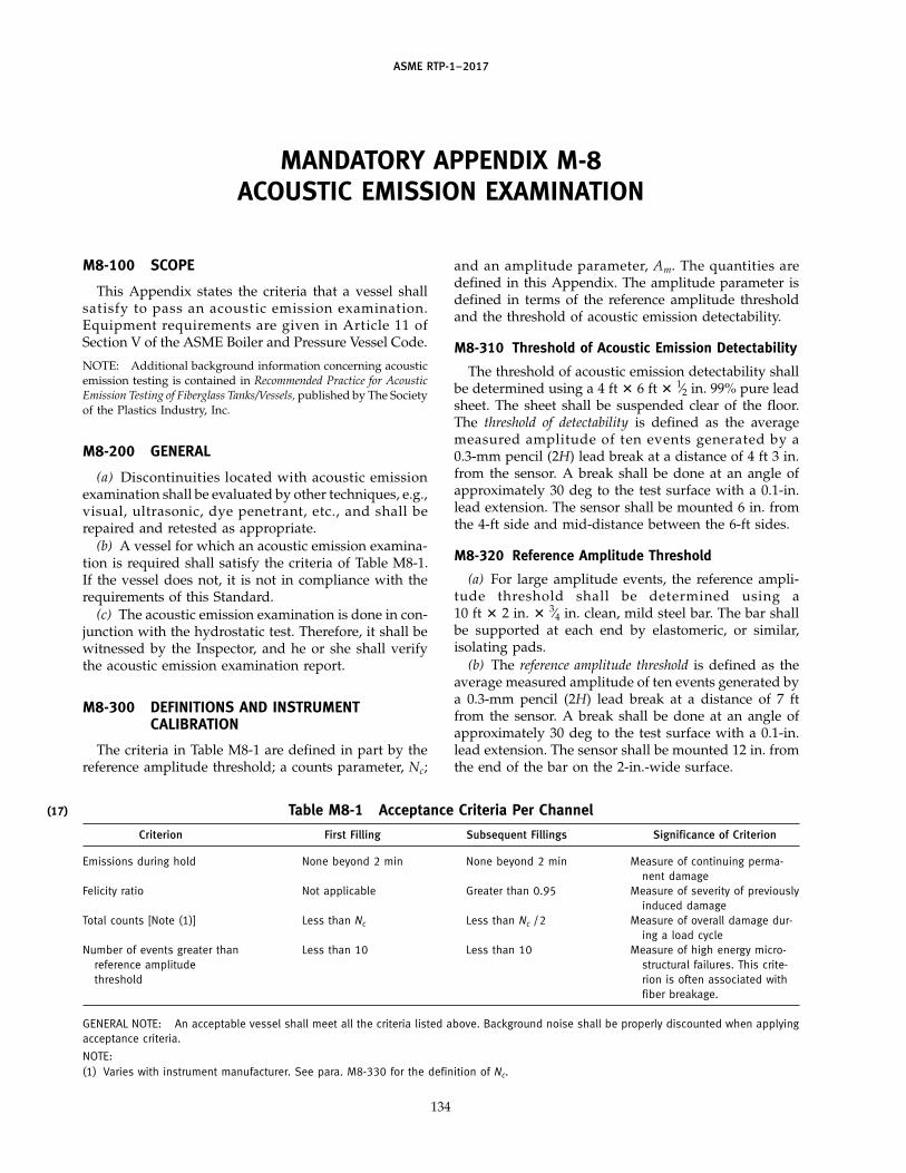
(17)
ASME RTP-1–2017
MANDATORY APPENDIX M-8ACOUSTIC EMISSION EXAMINATION
M8-100 SCOPE
This Appendix states the criteria that a vessel shallsatisfy to pass an acoustic emission examination.Equipment requirements are given in Article 11 ofSection V of the ASME Boiler and Pressure Vessel Code.
NOTE: Additional background information concerning acousticemission testing is contained in Recommended Practice for AcousticEmission Testing of Fiberglass Tanks/Vessels, published by The Societyof the Plastics Industry, Inc.
M8-200 GENERAL
(a) Discontinuities located with acoustic emissionexamination shall be evaluated by other techniques, e.g.,visual, ultrasonic, dye penetrant, etc., and shall berepaired and retested as appropriate.
(b) A vessel for which an acoustic emission examina-tion is required shall satisfy the criteria of Table M8-1.If the vessel does not, it is not in compliance with therequirements of this Standard.
(c) The acoustic emission examination is done in con-junction with the hydrostatic test. Therefore, it shall bewitnessed by the Inspector, and he or she shall verifythe acoustic emission examination report.
M8-300 DEFINITIONS AND INSTRUMENTCALIBRATION
The criteria in Table M8-1 are defined in part by thereference amplitude threshold; a counts parameter, Nc;
Table M8-1 Acceptance Criteria Per Channel
Criterion First Filling Subsequent Fillings Significance of Criterion
Emissions during hold None beyond 2 min None beyond 2 min Measure of continuing perma-nent damage
Felicity ratio Not applicable Greater than 0.95 Measure of severity of previouslyinduced damage
Total counts [Note (1)] Less than Nc Less than Nc /2 Measure of overall damage dur-ing a load cycle
Number of events greater than Less than 10 Less than 10 Measure of high energy micro-reference amplitude structural failures. This crite-threshold rion is often associated with
fiber breakage.
GENERAL NOTE: An acceptable vessel shall meet all the criteria listed above. Background noise shall be properly discounted when applyingacceptance criteria.
NOTE:(1) Varies with instrument manufacturer. See para. M8-330 for the definition of Nc.
134
and an amplitude parameter, Am. The quantities aredefined in this Appendix. The amplitude parameter isdefined in terms of the reference amplitude thresholdand the threshold of acoustic emission detectability.
M8-310 Threshold of Acoustic Emission Detectability
The threshold of acoustic emission detectability shallbe determined using a 4 ft � 6 ft � 1⁄2 in. 99% pure leadsheet. The sheet shall be suspended clear of the floor.The threshold of detectability is defined as the averagemeasured amplitude of ten events generated by a0.3-mm pencil (2H) lead break at a distance of 4 ft 3 in.from the sensor. A break shall be done at an angle ofapproximately 30 deg to the test surface with a 0.1-in.lead extension. The sensor shall be mounted 6 in. fromthe 4-ft side and mid-distance between the 6-ft sides.
M8-320 Reference Amplitude Threshold
(a) For large amplitude events, the reference ampli-tude threshold shall be determined using a10 ft � 2 in. � 3⁄4 in. clean, mild steel bar. The bar shallbe supported at each end by elastomeric, or similar,isolating pads.
(b) The reference amplitude threshold is defined as theaverage measured amplitude of ten events generated bya 0.3-mm pencil (2H) lead break at a distance of 7 ftfrom the sensor. A break shall be done at an angle ofapproximately 30 deg to the test surface with a 0.1-in.lead extension. The sensor shall be mounted 12 in. fromthe end of the bar on the 2-in.-wide surface.

ASME RTP-1–2017
M8-330 Count Criterion, Nc, and Am Value
(a) The count criterion, Nc, shall be determined eitherbefore or after the test using a 0.3-mm pencil (2H) leadbroken on the surface of the vessel. A break shall bedone at an angle of approximately 30 deg to the testsurface with a 0.1-in. lead extension. Calibration pointsshall be chosen so as to be representative of differentconstructions and thicknesses, and should be performedabove and below the liquid line (if applicable), and awayfrom manways, nozzles, etc.
(b) Two calibrations shall be carried out for each cali-bration point. One calibration shall be in the principaldirection of the surface fibers (if applicable), and thesecond calibration shall be carried out along a line at45 deg to the direction of the first calibration. Breaksshall be at a distance from the calibration point so as toprovide an amplitude decibel value, Am, midwaybetween the threshold of detectability and the referenceamplitude threshold.
The count criterion, Nc, shall be ten times the numberof counts recorded from seven lead breaks at each ofthe two calibration points. The lead breaks shall be done
135
with a 0.3-mm diameter (2H) pencil lead. The breaksshall be made with the lead at an angle of approximately30 deg to the test surface with a 0.1-in. lead extension.When applying the count criterion, the value that isrepresentative of the region where activity is observedshould be used.
M8-400 WRITTEN PROCEDURE REQUIREMENTS
Acoustic emission examinations shall be performedfollowing a written procedure. The procedure shall sat-isfy the requirements of para. T-1128 in Article 11 ofSection V of the ASME Boiler and Pressure Vessel Code.
M8-500 WRITTEN REPORT OF RESULTS
The results of an acoustic emission examination shallbe reported in a written document satisfying the require-ments of para. T-1190 in Article 11 of Section V of theASME Boiler and Pressure Vessel Code. The report shallbe made available for review and acceptance by theInspector.
Get more FREE standards from Standard Sharing Group and our chats
ASME RTP-1–2017
MANDATORY APPENDIX M-9GLOSSARY
accelerator: a material added to the resin to increase therate of polymerization (curing).
audit: a systematic review to assess the implementationof prescribed procedures, specifications, or standards.
axial: in the direction of the axis (lengthwise centerline)of the equipment.
Barcol hardness test: test to determine the surface indenta-tion hardness of the resin, which is directly related tothe degree of cure. The Barcol Impressor is the instru-ment used for measuring polyester and vinyl ester resinhardness (ASTM D2583).
binder: chemical treatment applied to the randomarrangement of glass fibers to give integrity to mats.Specific binders are utilized to promote chemical compa-tibility with the various laminating resins used.
blister: raised spot on the surface of a laminate causedby a subsurface air void.
bonding: joining of two or more parts by adhesive forces.
bond strength: force per unit area (psi) necessary to rup-ture a bond in interlaminar shear.
burned areas: areas of laminate showing evidence ofdecomposition (e.g., discoloration and/or cracking) dueto excessive resin exotherm.
burn out (burn off): thermal decomposition of organicmaterials (resins and binders) from a laminate specimenin order to determine the weight percent of resin andglass reinforcement (synthetic reinforcements decom-pose together with the resin and binder).
catalyst: an organic peroxide material used to activate thepolymerization reaction of a resin, causing it to harden(polymerization initiator).
certify: to attest, by signature and date, to conformanceto procedures, specifications, or standards. Where certi-fication is required by a Professional Engineer, certifica-tion shall include application of the PE stamp.
chopped strand mat: reinforcement made from randomlyoriented glass strands that are held together in mat formusing a binder. Each strand has a sizing.
chopper gun: a machine that is used to cut continuousfiberglass roving to predetermined lengths (usually 1⁄2 in.to 2 in.) and propel the cut strands to the mold surface.
136
In the spray-up process, a catalyzed resin spray is depos-ited simultaneously on the mold. When intersperse lay-ers are provided in filament winding, the resin spray isoften not used.
contact molding: process for molding RTP in which rein-forcement and resin are placed in or on a mold. Cure iseither at room temperature using a catalyst–promotersystem or by heat in an oven. Includes both hand lay-up and spray-up. For the purposes of this Standard,laminates manufactured with a process other than fila-ment winding are contact molded.
corrosion layer (barrier): see paras. 2A-221 and 2A-222.
coverage: in hoop filament winding, the complete cov-ering of the mandrel surface by a single layer of glassreinforcement and resin. In helical winding, two layersmust be applied to achieve one coverage.
crazing: the formation of tiny hairline cracks in varyingdegrees throughout the resin matrix, particularly inresin-rich areas.
critical service: see para. 1-210(c).
curing agents: materials used to initiate the polymeriza-tion of a resin. The catalyst is the primary agent. Promot-ers and accelerators are secondary or assisting agents.
cut edge: end of a laminate resulting from cutting thatis not protected by a corrosion barrier.
delamination: physical separation or loss of bond betweenlaminate plies.
dished end: radiused end closure for a cylindrical vessel,as opposed to a flat or coned end.
dry spot: an area where the reinforcement fibers have notbeen sufficiently wetted with resin.
edge sealing: application of reinforcement and resin, orresin alone, to seal cut edges and provide a corrosionresistant barrier. The final layer of resin shall beparaffinated.
entrapped air void: cavity in a laminate caused by atrapped gas bubble.
environment: state of the surroundings in contact withthe internal or external surface. Included are the temper-ature, pressure, chemical exposure, exposure to sunlight,relative humidity, liquids, and/or gases.
equipment: vessels used for the storage, accumulation,or processing of corrosive or otherwise hazardous sub-stances at pressures ranging from full vacuum to 15 psig.

ASME RTP-1–2017
equipment assembler: person who puts together the com-ponent parts, e.g., joining sections, installation of noz-zles, etc.
exotherm: evolution of heat by the resin during the poly-merization reaction. The word exotherm is often used,however, to designate the maximum temperaturereached during the polymerization process.
exotherm ply: that ply of chopped strand mat at whichthe lamination process is stopped to allow gelation andexotherm of the existing laminate.
exterior layer: outer surface layer of a laminate; seepara. 2A-224.
Fabricator: producer of RTP equipment. The Fabricatorcombines resin and reinforcing fibers to produce thefinal product.
fiber(glass): a fine solid thread of glass.
fiberglass roving: a number of strands or filaments of glassfibers gathered together with little or no twist.
fiberglass woven roving: heavy fabric woven from glassfiber rovings.
fiber wetting: coating (wetting) of the fiberglass with resinby means of roll-out or immersion.
filament: see fiber.
filament winding: a process for forming RTP parts bywinding either dry or resin-saturated continuous rovingstrands onto a rotating mandrel.
fillers: inert materials that are added to the resin toincrease density, increase viscosity, improve abrasionresistance, enhance resin application properties,decrease resin shrinkage, reduce cost, etc.
fill picks: the rovings in a woven roving that run in thetransverse direction of the fabric, i.e., across the rollwidth of the fabric.
fit-up: the match between joining parts, elements, orcomponents.
flame retardant resin: halogenated resins that can be usedwith or without additives to provide a laminate havinga reduced flame spread as measured in accordance withNFPA 255, Standard Method of Surface BurningCharacteristics of Building Materials (UL723,ASTM E84). The resins are not fire retardant in theirliquid state.
flame spread rating: index number resulting from testingin accordance with NFPA 255, Standard Method ofSurface Burning Characteristics of Building Materials(UL723, ASTM E84).
gap filling: the filling of voids between joined parts, ele-ments, or components with resin putty or resin.
gel: the initial jellylike solid phase that develops duringthe polymerization of resin.
137
gel time: time from the initial mixing of the resin withcatalyst to when gelation begins.
glass content: weight percent of glass fiber reinforcementin the laminate.
gun roving: fiberglass roving designed for use in a chop-per gun for spray-up application.
hand lay-up: a method of contact molding wherein theglass fiber reinforcement is applied to the mold, in theform of chopped strand mat or woven roving, by handor from a reel. The resin matrix is applied by variousmethods including brush, roller, or spray gun. Consoli-dation of the composite laminate is by rolling.
heat deflection temperature: temperature at which a speci-fied bar specimen deflects 0.010 in. when loaded as asimple beam to a constant 264 psi (see ASTM D648, TestMethod for Deflection Temperature of Plastics UnderFlexural Load). Usually refers to a resin casting, not alaminate.
helical winding: filament winding where the reinforce-ment is placed at some angle (other than 0 deg or 90 deg)to the axis of rotation.
hot patch: several small fiberglass mat tabs, saturatedwith highly catalyzed resin, used to hold butted orjoined parts or components in preparation for bonding.
hydrostatic test: pressure test of equipment using wateras the test medium.
independent testing laboratory: the laboratory conductingthe tests required by RTP-1 must be an entity separateorganizationally, legally, and financially from theFabricator and User or User’s Agent. Additionally, nocommercial, financial, or individual relationships shallexist between the parties that might compromise effortsto produce and report accurate test results. It is expected,however, that a commercial purchase order, contract, oragreement will be employed by the parties to arrangefor testing services. The independent testing laboratorymust be equipped and staffed with the necessary skilledpersonnel to conduct the tests in accordance with therequirements of the Standard.
initiator: see catalyst.
inner surface: see para. 2A-221.
interior layer: see para. 2A-222.
intersperse: chopped fiberglass used in a filament woundlaminate, usually in thin layers between windingcoverages.
isophthalic polyester: a polyester made from isophthalicacid.
joint overlay: an overlay laminate that joins the adjoiningsurfaces of two contacting parts or elements.
laminate: the total of the part constructed by combiningone or more layers of material (reinforcement and/orresin). As used in this Standard, the corrosion laminate
Get more FREE standards from Standard Sharing Group and our chats

ASME RTP-1–2017
consists of the corrosion-resistant barrier, the structurallayer, and the outer surface.
laminate composition: the sequence of reinforcementmaterials on a type, class, and category basis that makeup a laminate.
laminate element: a part of the structural layer of a fila-ment wound laminate that is described by the windangle, number of coverages with supplementary rein-forcement (if used), and the required sequence.
laminate structure (Type I, hand lay-up): see Table 2A-1.
laminate structure (Type II, hand lay-up): see Table 2A-2.
laminate structure (Type X): see Subpart 2A.
lamination analysis: procedure by which, given theamount and properties of the resin and the propertiesand orientation of the reinforcement, it is possible tocalculate the elastic properties of the individual layersand the total laminate.
layout: the arrangement and location of parts, elements,and/or components that reflect the design of a product.
leno strands: a pair of warp ends at each edge of a wovenfiberglass fabric.
liner: see paras. 2A-221 and 2A-222.
longitudinal: see axial.
lot, resin: a resin lot is a quantity of resin that is formu-lated to its final composition in a single vessel, testedand assigned a unique number, and covered by a certifi-cate of analysis.
mandrel: mold around which a laminate is formed tofabricate a cylindrical section.
Manufacturers: producers of materials of construction,e.g., resin, reinforcement fibers, catalysts, common addi-tives, etc.
manway: large nozzle or opening in a vessel for the pur-pose of entry by personnel.
materials: ingredients (reinforcements, resins, catalysts,and common additives) that are used to fabricate theequipment.
matrix: resin phase of a fiberglass resin composite.
minor repairs: repairs that do not exceed the area of repairallowed in Part 6 and meet the minimum visual accept-ance level indicated in the UBRS.
mold: the form over which or into which resin and rein-forcements are placed to form the composite productshape.
mold release agents: see parting agents.
monomer: a basic compound that can react with itself toform a polymer.
MSPI: Manufacturer’s Specific Product Identification.
oblation: the process by which cylindrical tank shells arecompressed to create shapes varying from oval to figure
138
eight. This action is taken to facilitate over-the-road ship-ment or installation in a confined space.
original document: the original source document or areproduction of the original source document bearingan original signature.
overlay: laminates used over base RTP structures tosecure a joint, seal a seam, attach a nozzle, etc.
paraffinated resin: resin containing a small amount ofdissolved paraffin (usually 0.1% to 0.5%). Polymeriza-tion of polyesters is inhibited by contact with the atmo-sphere. During cure, the paraffin migrates to the surface,sealing it against atmospheric exposure.
parting agents: also called mold release agents. Compoundsthat assist in releasing an RTP part from its mold.
peroxide catalyst: see catalyst.
pit: small crater in the surface of the laminate (seeTable 6-1).
polyester resin: resin produced by the polycondensationof dihydroxy derivatives and dibasic organic acids oranhydrides, wherein at least one component contributesethylenic unsaturation yielding resins that can be com-pounded with styryl monomers and reacted to givehighly cross-linked thermoset resins.
postcuring: process of applying heat (180°F to 200°F) toan RTP part, following the exotherm cycle. Proper post-curing will shorten the time to total cure.
profile: the roughness (smoothness) of the surface.
promoter: a material that activates the catalyst that curesthe resin (also see accelerator).
PVA: abbreviation for polyvinyl alcohol, a parting agent.
quality assurance: the system by which the Fabricatorprovides evidence that the quality control system hasbeen followed in the construction of the product.
quality control: the system a Fabricator uses to fabricatethe equipment in compliance with this Standard.
referee samples: laminate specimens submitted to estab-lish a level of quality for judging acceptance/rejectionof production equipment.
reinforcement: glass fibers having the form of choppedroving, continuous roving, fabric, or chopped strandmat. These fibers are added to the resin matrix tostrengthen and improve the properties of the resin.
release film: film used to facilitate removal of the partfrom the mold or mandrel. Oriented polyester film,3–5 mil (Mylar®, Types A, S, or D; or Melinex 11®, TypesS, O, or 442), has been found suitable for this purpose.
resin: the matrix of the laminate.
resin putty: resin filled with clay, fumed silica, milledglass fibers, or other inert materials to provide puttylikeconsistency.
ASME RTP-1–2017
resin rich layer: term often used to describe the corrosionbarrier. The term does not imply excessive resin content.
resin richness: excessive amounts or uneven distributionof resin in the laminate. Such areas are subject to crack-ing. Resin richness is the result of improper wet-outprocedures as well as inadequate or improper roll-outtechniques or drainage.
roll-out: densification of the laminate by working rein-forcement into the resin and the air out of the resin usinga roller (a serrated metal or thermoplastic roller is oftenused for this purpose).
rough profile: the result of sanding, machining, or other-wise abrading a laminate surface to produce a rough-ened surface for bonding.
roving: a plurality of strands or filaments gatheredtogether with little or no twist in a package known asa roving ball.
RTP: reinforced thermoset plastic.
secondary bond strength: adhesive force that holds a sepa-rately cured laminate to the basic substrate laminate.
sizing: surface treatment or coating applied to filamentsto improve the filament-to-resin bond.
slugs: unfiberized beads of glass.
spray-up: method of contact molding wherein resin andchopped strands of continuous filament glass fiber rov-ing are deposited on the mold directly from a chop-per gun.
strain: elongation per unit length.
strand: a plurality of filaments gathered together andbonded with sizing.
stress: load per unit area.
structural layer: the portion of the laminate constructionproviding the primary mechanical strength.
surface preparation: the act of roughening, priming, orotherwise treating laminate surfaces to achieve surfaceconditions that are conducive to adhesion of subse-quently applied laminate bonds.
139
surfacing veil: thin mat of fiberglass, synthetic organicfiber, or carbon fiber that is used to reinforce the corro-sion-resistant resin-rich layer on the inside or outside ofequipment or to provide a smooth surface on the outsideof equipment.
Tex: linear density of roving expressed in grams per1 000 m.
Type I, Type II, and Type X laminates: see laminate structure.
unidirectional rovings: continuous parallel roving strandsof glass fibers held together with periodic cross strands.
User: organization for which the equipment is beingfabricated.
UV absorber: compounds that are added to resins toenhance their ultraviolet resistance.
veil: see surfacing veil.
vinyl ester resin: resin characterized by reactive unsatura-tion located predominately in terminal positions whichcan be compounded with styryl monomers and reactedto give highly cross-linked thermoset copolymers.
visual acceptance criteria: see para. 6-940.
voids: unfilled space caused by air or gas in the resinmix or by entrapment of such gases during lay-up ofindividual plies of glass. Excessive voids reduce thestrength and chemical resistance of the laminate, partic-ularly if the voids are at the resin–glass interface.
warp ends: the roving in a woven roving that runs in thelongitudinal direction of the fabric, i.e., along the rolllength of the fabric.
wind angle: angle from the axis of rotation at which thereinforcement strands are placed in the filament windingprocess.
wind cycle: in filament winding, one traversing of thecarriage to the end of the mandrel and return to theoriginal position. Depending on bandwidth, part diame-ter, and wind angle, one or more wind cycles will beneeded to achieve one coverage.
yield: linear density of roving, expressed in yards perpound.
Get more FREE standards from Standard Sharing Group and our chats

(17)
ASME RTP-1–2017
MANDATORY APPENDIX M-10REFERENCE DOCUMENTS
The following is a list of publications referenced in thisStandard. The latest revisions of all references should beutilized.
AISC, Manual of Steel ConstructionPublisher: American Institute of Steel Construction
(AISC), 1 East Wacker Drive, Suite 700, Chicago, IL60601 (www.aisc.org)
API Standard 650, Welded Steel Tanks for Oil StoragePublisher: American Petroleum Institute (API),
1220 L Street, NW, Washington, DC 20005(www.api.org)
ASCE 7, Minimum Design Loads for Buildings andOther Structures
Publisher: American Society of Civil Engineers (ASCE),1801 Alexander Bell Drive, Reston, VA 20191(www.asce.org)
ASME B16.5, Pipe Flanges and Flanged FittingsASME B18.21.1, Washers: Helical Spring-Lock, Tooth
Lock, and Plain Washers (Inch Series)ASME B31.3, Process PipingASME BPVC Section II — MaterialsASME BPVC, Section V — Nondestructive Examination,
Subsection A, Article 11, Acoustic EmissionExamination of Fiber-Reinforced Plastic
ASME BPVC Section VIII — Rules for Construction ofPressure Vessels
ASME CA-1, Conformity Assessment RequirementsPublisher: The American Society of Mechanical
Engineers (ASME), Two Park Avenue, New York, NY10016-5990 (www.asme.org)
ASQ Z1.4, Sampling Procedures and Tables forInspection by Attributes
Publisher: American Society for Quality (ASQ),P.O. Box 3005, Milwaukee, WI 53201 (www.asq.org)
ASTM C177, Standard Test Method for Steady-StateHeat Flux Measurements and Thermal TransmissionProperties by Means of the Guarded-Hot-PlateApparatus
ASTM C581, Standard Practice for DeterminingChemical Resistance of Thermosetting Resins Used inGlass-Fiber-Reinforced Structures Intended for LiquidService
ASTM C582, Standard Specification for Contact-MoldedReinforced Thermosetting Plastic (RTP) Laminates forCorrosion-Resistant Equipment
140
ASTM D638, Standard Test Method for TensileProperties of Plastics
ASTM D648, Standard Test Method for DeflectionTemperature of Plastics Under Flexural Load in theEdgewise Position
ASTM D696, Standard Test Method for Coefficient ofLinear Thermal Expansion of Plastics Between −30°Cand 30°C With a Vitreous Silica Dilatometer
ASTM D790, Standard Test Methods for FlexuralProperties of Unreinforced and Reinforced Plasticsand Electrical Insulating Materials
ASTM D792, Standard Test Methods for Density andSpecific Gravity (Relative Density) of Plastics byDisplacement
ASTM D883, Standard Terminology Relating to PlasticsASTM D1248, Standard Specification for Polyethylene
Plastics Extrusion Materials for Wire and CableASTM D1593, Standard Specification for Nonrigid Vinyl
Chloride Plastic Film and SheetingASTM D1599, Standard Test Method for Resistance to
Short-Time Hydraulic Pressure of Plastic Pipe, Tubing,and Fittings
ASTM D1781, Standard Test Method for Climbing DrumPeel for Adhesives
ASTM D1784, Standard Specification for Rigid Poly(Vinyl Chloride) (PVC) Compounds and ChlorinatedPoly(Vinyl Chloride) (CPVC) Compounds
ASTM D1785, Standard Specification for Poly(VinylChloride) (PVC) Plastic Pipe, Schedules 40, 80, and 120
ASTM D2241, Standard Specification for Poly(VinylChloride) (PVC) Pressure-Rated Pipe (SDR Series)
ASTM D2583, Standard Test Method for IndentationHardness of Rigid Plastics by Means of a BarcolImpressor
ASTM D2584, Standard Test Method for Ignition Lossof Cured Reinforced Resins
ASTM D3039, Standard Test Method for TensileProperties of Polymer Matrix Composite Materials
ASTM D3159, Standard Specification for ModifiedETFE-Fluoropolymer Molding and ExtrusionMaterials
ASTM D3167, Standard Test Method for Floating RollerPeel Resistance of Adhesives
ASTM D3222, Standard Specification for UnmodifiedPoly(Vinylidene Fluoride) (PVDF) Molding Extrusionand Coating Materials

ASME RTP-1–2017
ASTM D3275, Standard Classification System forE-CTFE-Fluoroplastic Molding, Extrusion, andCoating Materials
ASTM D3294, Standard Specification for PTFE ResinMolded Sheet and Molded Basic Shapes
ASTM D3307, Standard Specification forPerfluoroalkoxy (PFA)-Fluorocarbon Resin Moldingand Extrusion Materials
ASTM D3350, Standard Specification for PolyethylenePlastics Pipe and Fittings Materials
ASTM D3368, Standard Specification for FEP-Fluorocarbon Sheet and Film
ASTM D3846, Standard Test Method for In-Plane ShearStrength of Reinforced Plastics
ASTM D4101, Standard Specification for PolypropyleneInjection and Extrusion Materials
ASTM D4285, Standard Test Method for Indicating Oilor Water in Compressed Air
ASTM D4444, Standard Test Methods for LaboratoryStandardization and Calibration of Hand-HeldMoisture Meters
ASTM D4895, Standard Specification forPolytetrafluoroethylene (PTFE) Resin Produced FromDispersion
ASTM D5083, Standard Test Method for TensileProperties of Reinforced Thermosetting Plastics UsingStraight-Sided Specimens
ASTM D5162, Standard Practice for Discontinuity(Holiday) Testing of Nonconductive ProtectiveCoating on Metallic Substrates
ASTM D5575, Standard Classification Systems forCopolymers of Vinylidene Fluoride (VDF) With OtherFluorinated Materials
ASTM E84, Standard Test Method for Surface BurningCharacteristics of Building Materials
Publisher: American Society for Testing and Materials(ASTM International), 100 Barr Harbor Drive, P.O. BoxC700, West Conshohocken, PA 19428-2959(www.astm.org)
AWS B2.4, Specification for Welding Procedure andPerformance Qualification for Thermoplastics
AWS D1.1, Structural Welding Code — SteelAWS G1.10M, Guide for the Evaluation of Thermoplastic
WeldsPublisher: American Welding Society (AWS), 8669 NW
36 Street, No. 130, Miami, FL 33166 (www.aws.org)
Barbero, E. J., Introduction to Composite MaterialsDesign, Taylor and Francis, Boca Raton, FL (1998)
BS 4994, Specification for Design and Construction ofVessels and Tanks in Reinforced Plastics
BS 6399-2, Loading for Buildings, Code of Practice forWind Loads
Publisher: British Standards Institution, Inc. (BSI), 12950Worldgate Drive, Suite 800, Herndon, VA 20170(www.bsigroup.com)
141
Christensen, R. M., Mechanics of Composite Materials,Dover Publications, Mineola, NY (2005)
Christensen, R. M., and Lo, K. H., Solutions for EffectiveShear Properties in Three Phase Sphere and CylinderModels, Journal of the Mechanics and Physics of Solids,Vol. 27, 315–330 (1979)
EN 1991, Eurocode 1, Actions on structuresEN 1998, Eurocode 8, Design of structures for earthquakeEN 13121, GRP tanks and vessels for use above groundPublisher: European Committee for Standardization
(CEN), Avenue Marnix 17, B-1000, Brussels, Belgium(www.cen.eu)
Hashin, Z., Analysis of Properties of Fiber CompositesWith Anisotropic Constituents, Journal of AppliedMechanics, Vol. 46, 543–550 (1979)
International Building CodeStandard Building CodeUniform Building CodePublisher: International Code Council (ICC), 500 New
Jersey Avenue, NW, Washington, DC 20001(www.iccsafe.org)
ISO 14130, Fibre-reinforced plastic composites —Determination of apparent interlaminar shearstrength by short-beam method
Publisher: International Organization forStandardization (ISO), Central Secretariat, Chemin deBlandonnet 8, Case Postale 401, 1214 Vernier, Geneva,Switzerland (www.iso.org)
Jones, R. M., Mechanics of Composite Materials, SecondEdition, Taylor and Francis, Philadelphia (1999)
Manual de Diseno de Obras CivilesPublisher: Comision Federal de Electricidad, Reforma
164, Col. Juarez, Cuauhte moc, Mexico(www.cfe.gob.mx)
MIL-HDBK-17-3F, Composite Materials Handbook,Vol. 3: Polymer Matrix Composites Materials Usage,Design, and Analysis
Publisher: U.S. Army Research Laboratory, Weapons andMaterials Research Directorate, Aberdeen ProvingGround, MD 21005-5069 (www.arl.army.mil)
NASA, SP-8007, Buckling of Thin-Walled CircularCylinders
Publisher: NASA Langley Research Center, Hampton,VA 23681 (www.sti.nasa.gov)
National Building CodePublisher: American Insurance Association (AIA), 2101
L Street, NW, Suite 400, Washington, DC 20037(www.aiadc.org)
National Building Code of Canada
Get more FREE standards from Standard Sharing Group and our chats
ASME RTP-1–2017
Publisher: National Research Council Canada, 1200Montreal Road, Ottawa, Ontario, K1A-0R6, Canada(www.nrc-cnrc.gc.ca/eng)
NFPA 255, Standard Method of Test of Surface BurningCharacteristics of Building Materials
Publisher: National Fire Protection Association (NFPA),1 Batterymarch Park, Quincy, MA 02169(www.nfpa.org)
Recommended Practice for Acoustic Emission Testingof Fiberglass Tanks/Vessels
Publisher: Plastics Industry Association, 1425K Street, NW, Washington, DC 20005(www.plasticsindustry.org)
142
UL 723, Standard Test for Surface BurningCharacteristics of Building Materials
Publisher: Underwriters Laboratories, Inc. (UL), 333Pfingsten Road, Northbrook, IL 60062-2096; OrderAddress: Comm 2000, 151 Eastern Avenue,Bensenville, IL 60106 (www.ul.com)
University of Delaware Center for CompositesMaterials, Delaware Composites DesignEncyclopedia, CRC Press, Boca Raton FL
Vinson, J. R., and Sierakowski, R. L., The Behavior ofStructures Composed of Composite Materials, KluwerAcademic Publishers, Dordrecht, The Netherlands(1987)

ASME RTP-1–2017
MANDATORY APPENDIX M-11SUBMITTAL OF TECHNICAL INQUIRIES TO THE REINFORCEDTHERMOSET PLASTIC CORROSION-RESISTANT EQUIPMENT
COMMITTEE
M11-100 INTRODUCTION
(a) The ASME Reinforced Thermoset PlasticCorrosion-Resistant Equipment Committee and its sub-committees and task groups meet regularly to considerrevisions of the rules, new rules as dictated by techno-logical development, Cases, and interpretations. ThisAppendix provides guidance to users for submittingtechnical inquiries to the Committee. Technical inquiriesinclude requests for revisions or additions to the rules,requests for Cases, and requests for interpretations.
(b) Cases may be issued by the Committee when theneed is urgent. Cases clarify the intent of existingrequirements or provide alternative requirements. Casesare written as a Question and a Reply, and are usuallyintended to be incorporated into the Standard at a laterdate. Interpretations provide the meaning of or the intentof existing rules in the Standard and are also presentedas a Question and a Reply. Both Cases and interpreta-tions are published by the Committee.
(c) The rules, Cases, and interpretations establishedby the Committee are not to be considered as approving,recommending, certifying, or endorsing any proprietaryor specific design, or as limiting in any way the freedomof Fabricators or constructors to choose any method ofdesign or any form of construction that conforms tothe rules.
(d) As an alternative to the requirements of thisAppendix, members of the Committee and its subcom-mittees and task groups may introduce requests for revi-sions or additions, Cases, and interpretations at theirrespective committee meetings.
(e) Inquiries that do not comply with the provisionsof this Appendix or that do not provide sufficient infor-mation for the Committee’s full understanding mayresult in the request being returned to the inquirer withno action.
M11-200 INQUIRY FORMAT
Submittals to the Committee shall include thefollowing:
(a) Purpose. Specify(1) revision of present rule(s)(2) new or additional rule(s)
143
(3) Case or(4) interpretation
(b) Background. Provide the information needed forthe Committee’s understanding of the inquiry, beingsure to include reference to the applicable edition, para-graphs, figures, and tables. Preferably, provide a copyof the specific referenced portions of the Standard.
(c) Presentations. The inquirer may desire or be askedto attend a meeting of the Committee to make a formalpresentation or to answer questions from the Committeemembers with regard to the inquiry. Attendance at acommittee meeting shall be at the expense of theinquirer. The inquirer’s attendance or lack of attendanceat a meeting shall not be a basis for acceptance or rejec-tion of the inquiry by the Committee.
M11-300 REVISIONS OR ADDITIONS
Requests for revisions or additions shall provide thefollowing:
(a) Proposed Revision(s) or Addition(s). For revisions,identify the rules of the Standard that require revisionand submit a copy of the appropriate rules as theyappear in the Standard, marked up with the proposedrevision. For additions, provide the recommendedwording referenced to the existing rules.
(b) Statement of Need. Provide a brief explanation ofthe need for the revision(s) or addition(s).
(c) Background Information. Provide backgroundinformation to support the revision(s) or addition(s),including any data or changes in technology that formthe basis for the request that will allow the Committeeto adequately evaluate the proposed revision(s) or addi-tion(s). Sketches, tables, figures, and graphs should besubmitted as appropriate. When applicable, identify anypertinent paragraph in the Standard that would beaffected by the revision(s) or addition(s), and identifyparagraphs in the Standard that reference the para-graphs that are to be revised or added.
M11-400 CASES
Requests for Cases shall provide a Statement of Needand Background Information similar to that defined in
Get more FREE standards from Standard Sharing Group and our chats

ASME RTP-1–2017
paras. M11-300(b) and (c), respectively, for revisions oradditions. The proposed Case should be written as aQuestion and a Reply in the same format as any existingCases. Requests for Cases should also indicate the appli-cable edition(s) and addenda to which the proposedCase applies.
M11-500 INTERPRETATIONSRequests for interpretations shall provide the
following:(a) Provide a condensed and precise Question, omit-
ting superfluous background information and, whenpossible, composed in such a way that a “yes” or a “no”Reply, possibly with brief provisos, is acceptable. TheQuestion should be technically and editorially correct.
(b) Provide a proposed Reply that will clearly andconcisely answer the Question. Preferably, the Replyshould be “yes” or “no,” possibly with brief provisos.
(c) Background Information. Provide any backgroundinformation that will assist the Committee in under-standing the proposed Question and Reply.
144
M11-600 SUBMITTALS
Submittals to and responses from the Committee shallmeet the following:
(a) Submittal. Inquiries from users shall preferably besubmitted in typewritten form; however, legible hand-written inquiries will also be considered. They shallinclude the name, address, telephone number, and faxnumber, if available, of the inquirer and be mailed tothe following address:
Secretary, RTP Standards CommitteeThe American Society of Mechanical EngineersTwo Park AvenueNew York, NY 10016-5990
(b) Response. The Secretary of the Committee shallacknowledge receipt of each properly prepared inquiryand shall provide a written response to the inquirer uponcompletion of the requested action by the Committee.

(17)
ASME RTP-1–2017
MANDATORY APPENDIX M-12DUAL LAMINATE VESSELS
M12-100 INTRODUCTION
This Appendix includes the following:
Article A General RequirementsArticle B MaterialsArticle C DesignArticle D FabricationArticle E Inspection and TestArticle F Shipping and HandlingArticle G Shop QualificationArticle H Qualification of WeldersArticle I Glossary
ARTICLE AGENERAL REQUIREMENTS
M12A-100 SCOPE
(a) This Appendix describes fabrications that utilize astructural member that shall be fabricated in accordancewith ASME RTP-1 and is lined with thermoplastic asspecified in the UBRS. The thermoplastic sheet linerserves as the primary corrosion barrier and eitherreplaces or augments the corrosion-resistant barrier. Forcalculation purposes, the thermoplastic liner shall notbe considered in structural design of the fabrication.
(b) Equipment composed of a thermoplastic lininginside an RTP structural member is commonly called adual laminate structure.
(c) This Appendix specifies rules for the fabricationof a dual laminate where use of a thermoplastic liningmaterial is selected for special applications, e.g., contain-ment of aggressive corrosives, of ultra-pure fluids suchas deionized water, or of pharmaceutical chemicals,and/or for abrasive service.
(d) Special bonding materials and preparation proce-dures are required to ensure satisfactory bonding of theRTP structural laminate to the thermoplastic lining.
(e) This Appendix specifies requirements for qualify-ing personnel to weld the thermoplastic materials inorder to provide continuous leak/void-free corrosion-and abrasion-resistant liners that conform to the require-ments of this Standard.
(f) This Appendix lists the procedures for end user/customer inspection and quality assurance to meet therequirements for thermoplastic lined RTP equipment.
145
M12A-200 APPLICATION LIMITATIONS
Thermoplastic lined vessels certified by the Fabricatoras conforming to this Standard shall be lined only withthose thermoplastics described in Table M12B-1. Notethat the ASTM specifications in Table M12B-1 providethe minimum material specifications.
ARTICLE BMATERIALS
M12B-100 SCOPE
This Article defines the thermoplastic lining materialsthat are used to fabricate dual laminate equipment,including the joining or welding materials and the bond-ing materials to bond the thermoplastic lining to the RTPstructure. Bond strength requirements are also included.The RTP structural layer shall be in accordance withPart 2 of this Standard.
M12B-200 THERMOPLASTIC LINING MATERIALS
Thermoplastics are used as corrosion-resistant liningsin dual laminate constructions. These materials aredescribed in Tables M12B-1 and M12B-2. Table M12B-1contains the ASTM specifications for materials used inthis Standard. Table M12B-2 contains typical physicaland mechanical properties for general comparisons. Forpurposes of design and selection, the thermoplasticmanufacturer’s property data shall be used. Althoughmost thermoplastic sheet materials are supplied as indi-vidual flat sheets, some sheet materials may be suppliedas rolls. In this standard, sheet material is intended tomean both flat sheets and sheets supplied as rolls. Ther-moplastics used to construct the liner shall not containregrind. Thickness shall be as follows:
(a) Nominal lining thickness shall be from 0.080 in.to 0.200 in. (2.0 mm to 5.0 mm). The appropriate thick-ness for an application is a balance between thickerlinings, which allow less permeation, and thinner lin-ings, which result in less internal stress during forming.
(1) Lining thicknesses from 0.060 in. to 0.080 in.(1.5 mm to 2 mm) may be used if the Fabricator hasqualified in that thickness prior to fabricating a vessel.
(2) Linings over 0.200 in. (5.0 mm) may be used,but special design calculations shall be performed [seepara. M12C-500(a)].
(b) The thickness of a thermoplastic material with afiber backing is defined as the thickness from the process
(17)
(17)Get more FREE standards from Standard Sharing Group and our chats
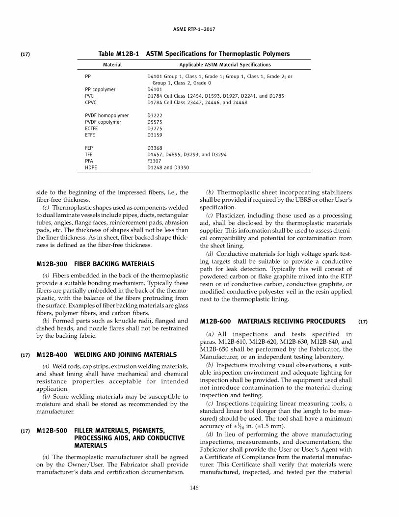
(17)
(17)
(17)
ASME RTP-1–2017
Table M12B-1 ASTM Specifications for Thermoplastic Polymers
Material Applicable ASTM Material Specifications
PP D4101 Group 1, Class 1, Grade 1; Group 1, Class 1, Grade 2; orGroup 1, Class 2, Grade 0
PP copolymer D4101PVC D1784 Cell Class 12454, D1593, D1927, D2241, and D1785CPVC D1784 Cell Class 23447, 24446, and 24448
PVDF homopolymer D3222PVDF copolymer D5575ECTFE D3275ETFE D3159
FEP D3368TFE D1457, D4895, D3293, and D3294PFA F3307HDPE D1248 and D3350
side to the beginning of the impressed fibers, i.e., thefiber-free thickness.
(c) Thermoplastic shapes used as components weldedto dual laminate vessels include pipes, ducts, rectangulartubes, angles, flange faces, reinforcement pads, abrasionpads, etc. The thickness of shapes shall not be less thanthe liner thickness. As in sheet, fiber backed shape thick-ness is defined as the fiber-free thickness.
M12B-300 FIBER BACKING MATERIALS
(a) Fibers embedded in the back of the thermoplasticprovide a suitable bonding mechanism. Typically thesefibers are partially embedded in the back of the thermo-plastic, with the balance of the fibers protruding fromthe surface. Examples of fiber backing materials are glassfibers, polymer fibers, and carbon fibers.
(b) Formed parts such as knuckle radii, flanged anddished heads, and nozzle flares shall not be restrainedby the backing fabric.
M12B-400 WELDING AND JOINING MATERIALS
(a) Weld rods, cap strips, extrusion welding materials,and sheet lining shall have mechanical and chemicalresistance properties acceptable for intendedapplication.
(b) Some welding materials may be susceptible tomoisture and shall be stored as recommended by themanufacturer.
M12B-500 FILLER MATERIALS, PIGMENTS,PROCESSING AIDS, AND CONDUCTIVEMATERIALS
(a) The thermoplastic manufacturer shall be agreedon by the Owner/User. The Fabricator shall providemanufacturer’s data and certification documentation.
146
(b) Thermoplastic sheet incorporating stabilizersshall be provided if required by the UBRS or other User’sspecification.
(c) Plasticizer, including those used as a processingaid, shall be disclosed by the thermoplastic materialssupplier. This information shall be used to assess chemi-cal compatibility and potential for contamination fromthe sheet lining.
(d) Conductive materials for high voltage spark test-ing targets shall be suitable to provide a conductivepath for leak detection. Typically this will consist ofpowdered carbon or flake graphite mixed into the RTPresin or of conductive carbon, conductive graphite, ormodified conductive polyester veil in the resin appliednext to the thermoplastic lining.
M12B-600 MATERIALS RECEIVING PROCEDURES
(a) All inspections and tests specified inparas. M12B-610, M12B-620, M12B-630, M12B-640, andM12B-650 shall be performed by the Fabricator, theManufacturer, or an independent testing laboratory.
(b) Inspections involving visual observations, a suit-able inspection environment and adequate lighting forinspection shall be provided. The equipment used shallnot introduce contamination to the material duringinspection and testing.
(c) Inspections requiring linear measuring tools, astandard linear tool (longer than the length to be mea-sured) should be used. The tool shall have a minimumaccuracy of ±1⁄16 in. (±1.5 mm).
(d) In lieu of performing the above manufacturinginspections, measurements, and documentation, theFabricator shall provide the User or User’s Agent witha Certificate of Compliance from the material manufac-turer. This Certificate shall verify that materials weremanufactured, inspected, and tested per the material
(17)

AS
ME
RTP-1–2017
(17) Table M12B-2 Typical Thermoplastic Polymer PropertiesPP PVDF
HDPE Homopolymer Copolymer PVC-U CPVC Homopolymer Copolymer ECTFE ETFE FEP PFA TFE
Density, g/cm3 0.94–0.96 0.91–0.92 0.90–0.91 1.38–1.44 1.46–1.54 1.75–1.79 1.75–1.80 1.68–1.71 1.70–1.74 2.1–2.2 2.12–2.17 2.2–2.3
Mechanical PropertiesTensile strength, MPa 19–32 30–41 24.0–38.0 41–52 48–62 31–57 20–48 45–57 40–52 21–30 21–31 20–40
Tensile strength, ksi 2.7–4.6 4.4–6.0 3.5–5.5 6.0–7.5 7.0–9.0 4.5–8.3 2.9–7.0 6.5–8.3 5.8–7.5 3.0–4.4 3.1–4.5 2.9–5.8
Tensile modulus, MPa 800–1 100 1 100–1 300 1 000–1 500 2 960–4 000 2 340–3 000 1 400–2 400 1 000–1 517 1 400–2 100 900–1 300 350–500 500–600 350–750
Tensile modulus, ksi 116–160 160–189 145–218 430–580 340–435 203–348 145–220 203–304 130–189 50–72.5 72.5–87 50–109
Elongation, % 10–1,000 20–800 >200 15–30 10–180 20–200 30–600 250–300 100–400 240–350 275–300 140–400
Yield strength, MPa 18–26 30–36 24–31 50–60 48–62 45–57 20–41 30–32 25 9–12 12–15 12
Yield strength, ksi 2.6–3.8 4.4–5.2 3.5–4.5 7.3–8.7 7.0–9.0 6.5–8.3 2.9–6.0 4.3–4.6 3.6 1.3–1.7 1.7–2.2 1.7
Thermal PropertiesHDT at 0.46 MPa 79–91 107–121 54–60 65 100–119 127–150 48–104 90 104 70 75 221
HDT at 66 psi 175–196 225–250 130–140 149 212–247 260–300 118–284 195 220 158 166 250
Linear thermal expan- 16–21 14.0–18.0 14.0–18.0 6.0–10.0 6.0–10.0 12.0–14.0 14–18 9 8–12 9–11 12–22 12–22sion coefficient,10−5/°C
Linear thermal expan- 9–12 8–10 8–10 3.3–5.6 3.3–5.6 6.7–8 8–10 5 4.4–7 5–6.1 7–12 7–12sion coefficient,10−5/°F
Thermal conductivity, 0.38–0.43 0.2–0.25 0.22–0.26 0.16–0.18 0.12 0.19–0.20 0.14–0.19 0.15 0.20 0.20–0.25 0.19–0.25 0.21–0.25W/m·K
Thermal conductivity, 2.6–2.9 1.4–1.7 1.5–1.8 1.1–1.2 0.81 1.33–1.40 0.98–1.33 0.95 1.40 1.4–1.69 1.33–1.7 1.48–1.69Btu/ft2-hr-°F/in.
GENERAL NOTE: Properties are at room temperature unless otherwise stated. Properties are typical values and are not to be used for design purposes. See para. M12B-200.
147
Get more FREE standards from Standard Sharing Group and our chats

(17)
(17)
(17)
ASME RTP-1–2017
supplier’s specifications. This does not apply to inspec-tions required in M12B-614.2(b).
M12B-610 Thermoplastic Sheet
M12B-611 Introduction. This section specifies theminimum inspections, tests, and acceptance criteria thatshall be performed on sheets or rolls of thermoplasticmaterial with or without backing.
M12B-612 Acceptance Inspection(a) Acceptance inspection shall include inspection of
sheets or rolls for proper packaging and identification,inspection for imperfections and contamination, andmeasurements of thickness, length, and width in accor-dance with acceptance requirements and limits definedin para. M12B-610.
(b) The thermoplastic sheet manufacturer shall spec-ify acceptable weld materials.
(c) The form shown in Table M12B-3, or a similar formthat contains the provisions to record the results of theserequired inspections, should be used by the Fabricatorand shall be retained in the inspection records. A sepa-rate form shall be used for each sheet/roll manufacturer,sheet nomenclature, backing material, and unitthickness.
M12B-613 Equipment and Measuring Tools Required
M12B-613.1 Thickness Measuring Tools(a) A standard micrometer with minimum accuracy
of ±0.001 in. (±0.025 mm) is required. The throat shouldallow thickness measurements at least 1 in. (25.4 mm)in from the edge of the sheet.
(b) Alternative tools are an ultrasonic thickness testeror a microscope equipped with a calibrated filar eyepiecethat measures across a properly prepared cross sectionof the sheet. These measuring tools shall have an accu-racy of ±0.001 in. (±0.025 mm) and shall be calibratedto demonstrate this accuracy with the specific thermo-plastic material being measured.
(c) In order to measure the thickness of a fiber-backedsheet using a micrometer, the embedded fibers on thefiber-backed side of the sheet shall be removed.
NOTE: A tool such as an appropriate hand scraper or a woodplane is suggested.
M12B-613.2 Linear Measuring Tools. Seepara. M12B-600(c). For rolls of thermoplastic sheet, thelength measurement may be made if desired by theFabricator.
M12B-613.3 Bond Strength Measuring Tools(a) The testing machine shall measure the load within
1% accuracy of the applied load. The testing range shallbe selected so that the maximum load on the specimenfalls between 15% and 85% of full scale capacityaccording to ASTM D1781.
148
(b) The Fabricator or independent testing laboratoryshall have the apparatus and sample holders requiredto perform the bond strength tests.
M12B-613.4 High Voltage Spark Test. An accept-able high voltage spark tester shall be used (seepara. M12D-500). The Fabricator shall have a docu-mented spark test procedure. A written report of thespark testing shall be retained by the Fabricator andavailable for the Owner/User. The report shall includedetails of the spark test including the operator/tester’sname, date and time of testing, test voltage, methodand frequency of verification of voltage calibration/veri-fication, and location/number of pinholes detected.Location of pinholes should be documented on the weldmap. Repair and retesting shall be documented in thetest document.
M12B-614 Procedures and Acceptance Limits
M12B-614.1 Sheet Identification and PackageInspection
(a) Verify on the inspection record that the sheet orroll as identified by the manufacturer has the samenomenclature as the sheet specified, and is the samematerial and ASTM specification as listed inTable M12B-1. Examine the packaging of the sheet fordamage that renders the sheet unusable. Indicate accept-able sheet by recording the date and name of the personperforming the examination in Table M12B-3, column 4.
(b) For packaged sheets that are acceptable for furtherinspection and tests, enter the sheet production date andlot number in Table M12B-3, columns 2 and 3.
M12B-614.2 Visual Inspection of ThermoplasticSheet or Roll
(a) The thermoplastic material shall be visuallyinspected for imperfections and contamination prior touse by the Fabricator. The defects and criteria listed inTable M12B-4 will be used.
(b) Fiber backing shall be visually inspected for ade-quate embedding, mechanical damage, dryness, andcontamination. The damage or removal of a protectivefilm shall be noted. Sheet backing that contains moistureshall be dried and used only if the backing is polyesteror acrylic fiber; all other fibers that show evidence ofhaving moisture shall be cause for rejection of the ther-moplastic sheet. Any sheet backing that has beenexposed to any other contaminants shall be rejected.
(c) The date and inspector’s name shall be recordedafter inspection in Table M12B-3, column 7. All defectsfound that are cause for rejection shall be recorded. Thereason for the rejection shall be recorded under the com-ments section in Table M12B-3.
(d) Areas of sheets that have defects greater thanallowed in Table M12B-4 shall not be repaired and shallnot be used.
(17)
(17)

ASME RTP-1–2017
Table M12B-3 Thermoplastic Sheet or Roll Receiving Log
Fabricator’s name Manufacturer
Address Nomenclature
Backing material and type of weave or felt
Shop order no. Manufacturer’s label thickness
1 2 3 4 5 6 7 8 9
Sample Production Lot, Batch, or Packaging Thickness Dimensions Visual Bond Strength CommentsDate Production Run Inspection Measured Inspection Measured
By Date By Date By Date By Date
Comments on visual and packaging inspection (indicate which sheet or roll):
GENERAL NOTE: This form may be reproduced and used without written permission from ASME if used for purposes other than republication.
149
Get more FREE standards from Standard Sharing Group and our chats

(17)
(17)
ASME RTP-1–2017
Table M12B-4 Thermoplastic Sheet Visual Inspection Acceptance Criteria
Imperfection Name Definition of Imperfection Maximum Size or Amount of Imperfection Allowed
Foreign inclusions Particles in the sheet that are not of the Noneplastic or backing composition
Surface pits Small crater or hole in the surface of the None deeper than one-tenth of the sheet thickness norsheet larger than 1⁄32 in.; no more than 4/ft2
Scratches Willow marks, grooves, furrows, or chan- None deeper than 0.005 in. (0.13 mm) nor more than 4 in.nels caused by mechanical damage (100 mm) long
Dents, chips Impressions from impact or small pieces None deeper than one-tenth of the sheet thicknessbroken out of surface
Blisters (internal) Pores within sheet NoneWrinkles Uneven surface from distortion of the None
sheetCracks Linear fissures None
Orange peel Surface texture resembling the surface of Noneoranges
Burned particles, . . . Nonelumps, delamina-tions
Color . . . Uniform to the eyeDamage to fiber Snags, tears, knots None
backing
M12B-614.3 Sheet Thickness(a) Sheet thickness shall be measured at a minimum
every 6 in. across the width of the sheet edge. Measure-ments should be made using a caliper micrometer orultrasonic thickness tester, or using a microscope andmeasuring across a cross section using a filar eyepiece.Any measurement not within the requirements of (c) iscause for rejection. The minimum/maximum measure-ment shall be entered in Table M12B-3, column 5. Afterother dimensions are entered, the inspector shall enterthe date and his/her name in column 6 if all measure-ments are within the requirements of this Standard.
(b) Sufficient measurements should be made to ensurethat all of the material used is within thickness require-ments. Measurements across two widths at each endand at least every 50 ft of length shall be made andrecorded.
(c) The sheet’s measured fiber-free thickness shall be±10% of the specified nominal fiber-free thickness.
M12B-614.4 Bond Strength Requirements(a) Bond strength tests must be conducted on each
production run of thermoplastic material intended forlining in dual laminates. The bonded sample will bemade using the RTP resin specified and the laminatingtechnique to be used in the vessel to be fabricated. Thethickness of the RTP laminate structure will be that thick-ness compatible with the selected bond strength testmethod.
(b) When a bonding resin is used, the bonding resinused to generate bond test samples will be the samebonding resin used to fabricate the vessel.
150
(c) Bond strength tests must be performed with theconductive target in place over the entire test sample.
(d) The minimum bond strength results (excludingnozzle necks) are as follows:
(1) for the climbing drum test, ASTM D1781, thebond strength must be at least 50 in.-lb/in.
(2) for the lap shear test, ASTM D3846 or BS 4994B-10, the bond shear strength must be at least 1,015 psi(7 N/mm2)
(e) Separate records will be kept for each bondstrength test accomplished. Results will be maintainedin the Quality Control Log and the test operator willenter his/her initials and the date the test was made inTable M12B-3, column 8. Test results lower than thevalues in (d) will be entered in Table M12B-3 in thecomments section and will be cause for rejection of thatmaterial.
M12B-614.5 Disposition of NonconformingMaterial. Sheets with defective areas may be cut,routed, or sheared to remove and discard the defectiveareas. Care must be used in handling cracked or crazedsheets, as mechanical treatments may cause the crackto propagate. After eliminating areas with defects, theremaining material may be used.
M12B-620 Welding Consumables
M12B-621 Introduction. This section describes theminimum inspections, tests, and acceptance criteria tobe performed on thermoplastic welding consumables

ASME RTP-1–2017
used for filler materials in welding thermoplastic mate-rial to fabricate equipment to this Standard. Consum-ables include weld rod, continuous coils of weld “wire,”cap strips, and extrusion weld materials.
M12B-622 Acceptance Inspection(a) Acceptance inspection will include inspection of
welding materials for proper packaging and identifica-tion, inspection for imperfections and contamination,and measurement of dimensions. Acceptance require-ments and limits are defined in paras. M12B-624.1through M12B-624.3.
(b) The manufacturer of the sheet to be used willcertify that the weld materials are acceptable.
(c) The form shown in Table M12B-5, or a similar formthat contains the provisions to record the results of theserequired inspections, will be used by the Fabricator andwill be retained in the inspection records. A separateform will be used for each kind of weld material andfor each manufacturer.
M12B-623 Equipment and Measuring Tools Required
M12B-623.1 Inspection Table and Lights. Seepara. M12B-600(b).
M12B-623.2 Dimensional Measuring Tools. Astandard micrometer or caliper capable of measuringwith an accuracy of at least ±0.001 in. (±0.025 mm) isrequired.
M12B-624 Procedures and Acceptance Limits
M12B-624.1 Welding Material Identification andPackage Inspection
(a) The welding materials will not be repackaged dur-ing the distribution of the materials after the manufac-turer has shipped the materials. Verify and enter on theinspection record that the welding materials as identi-fied by the manufacturer have the same nomenclatureas the materials specified to produce the equipment. Forcap strips, indicate in Table M12B-5, column 1 whetherthe strip has a fiber backing and the kind of backing.Examine the packaging of the welding materials fordamage that renders the materials unusable. Indicateacceptable welding materials by recording the date andname of the person performing the inspection inTable M12B-5, column 4.
(b) For welding material lots found acceptable, enterthe material’s production date and lot number inTable M12B-5, columns 2 and 3.
M12B-624.2 Visual Inspection of WeldingConsumables
(a) The welding materials will be visually inspectedfor imperfections and contamination prior to use by theFabricator.
(b) The limits of imperfections found are as follows:(1) No foreign materials, including water, other flu-
ids, or particles, are allowed.
151
(2) Color of all welding materials in a given lot willbe uniform.
(3) There will be no bends or other irregularities inshape, including variations in cross section.
(4) There will be no porosity or bubbles.(5) Surface will be smooth with uniform
appearance.(c) After visual inspection, record the date and the
inspector’s name in Table M12B-5, column 5. If anydefect is found that is cause for rejection, record thereason in Table M12B-5, column 7.
M12B-624.3 Dimensions Inspection(a) The diameter of each rod or coiled welding “wire”
and the widths and thicknesses of other shapes will bemeasured. The results of these measurements will beentered in Table M12B-5.
(b) The inspector performing dimension measure-ments will enter his/her initials and the inspection datein Table M12B-5.
M12B-630 Bonding Resin
M12B-631 Introduction. The bonding resin forbonding PVC or CPVC to the RTP structure is appliedto the thermoplastic, which promotes a chemical bondto both the thermoplastic and the RTP overlay.
M12B-632 Acceptance Inspection(a) Acceptance inspection will include inspection of
the containers of bonding resin for proper packagingand identification, for evidence of damage to the resinor its container, for ensuring that the label on the con-tainer is proper, and testing for bonding strength.Acceptance requirements and limits are defined in paras.M12B-634.1 and M12B-634.2.
(b) The form shown in Table M12B-6, or a similarform that contains the provisions to record the results ofthese required inspections, will be used by the Fabricatorand will be retained in the inspection records. A separateform will be used for each lot of bonding resin received.
(c) The bonding resin will be tested for bond strengthin accordance with para. M12B-634.2.
M12B-633 Equipment and Measuring ToolsRequired. See para. M12B-600(b) for inspection tableand lights.
M12B-634 Procedures and Acceptance Limits
M12B-634.1 Resin Identification and PackagingInspection
(a) The resin will be packaged as shipped from theresin manufacturer ’s factory. The resin will not berepackaged in the distribution of the materials after theresin manufacturer has shipped the resin. Verify andenter in the inspection record that the resin as identifiedby the resin manufacturer has the same nomenclatureas the resin specified to bond the thermoplastic as speci-fied in the UBRS and the thermoplastic manufacturer’s
(17)
(17)
Get more FREE standards from Standard Sharing Group and our chats

ASME RTP-1–2017
Table M12B-5 Welding Material Receiving Log
Fabricator’s name Manufacturer
Address Nomenclature
Material shape
Nominal dimensions
1 2 3 4 5 6 7
Welding Production Lot, Batch, or Packaging Visual Dimensions CommentsMaterial Date Production Run Inspection Inspection
No. By Date By Date
1
2
3
4
5
6
7
8
9
10
11
12
13
14
GENERAL NOTE: This form may be reproduced and used without written permission from ASME if used for purposes other than republication.
152

ASME RTP-1–2017
Table M12B-6 Bonding Resin Receiving Log
Fabricator’s name Manufacturer
Address Nomenclature
1 2 3 4 5 6
Number Production Lot, Batch, or Packaging Bond Strength CommentsDate Production Run Inspection Test Results
[Note (1)]
By Date By Date
1
2
3
4
5
6
7
8
9
10
11
12
13
GENERAL NOTE: This form may be reproduced and used without written permission from ASME if used for purposes other than republication.
NOTE:(1) Indicate test used: C p climbing drum, P p peel test, L p lap shear test.
153
(17)
Get more FREE standards from Standard Sharing Group and our chats

(17)
ASME RTP-1–2017
instructions. Examine the packaging for damage thatrenders the resin unusable. Indicate acceptable lots ofresin by recording the date of manufacture and the nameof the person performing the examination inTable M12B-6, column 4.
(b) For lots of resin that are found to be acceptablefor further inspection and tests, enter the resin produc-tion date and lot number in Table M12B-6, columns 2and 3.
M12B-634.2 Bond Strength Measurement. Thebonding resin will be tested for bonding strength inaccordance with the provisions of paras. M12B-613.3and M12B-614.4. At least one bond strength test will beperformed for each lot of bonding resin received. Theresults will be entered in Table M12B-6, column 5. Lotsof resin that fail to meet the acceptance requirementswill not be used and a comment noting the failure tomeet the acceptance limits will be entered inTable M12B-6, column 6.
M12B-640 Conductive Spark Test Targets
M12B-641 Introduction. Conductive material isused to provide an electrically conductive layer behindthe thermoplastic lining and behind the weld joints inorder to allow valid high voltage spark tests to evaluatethe integrity of the weld joints and the thermoplasticsheet. Conductive materials for high voltage spark test-ing targets will consist of powdered carbon or flakegraphite mixed into the RTP resin, or of conductivecarbon, conductive graphite, or modified conductivepolyester veil in the resin, applied next to the thermo-plastic lining. If powder is used, it is mixed in the resinin sufficient quantity so that the cured resin is conductiveenough for spark testing. This resin mixture is thenapplied directly to the thermoplastic and entrapped airis removed. The fiber forms of carbon or polyester arelaid into resin already applied to the back of the weldor sheet. The conductive fiber mixture is then rolled, orotherwise treated, to remove entrapped air bubbles.
CAUTION: Some carbon and graphite materials can inhibitresin cure.
M12B-642 Acceptance Inspection(a) Acceptance inspection will include inspection of
the packaging and identification, and measurement ofelectrical conductivity of samples of resin mixed with aspecific amount of carbon or graphite, or samples ofresin and conductive polyester mixtures, used to gener-ate the conductive target.
(b) The form shown in Table M12B-7, or a similarform that contains the provisions to record the results ofthese required inspections, will be used by the Fabricatorand will be retained in the inspection records. A separateform will be used for each carbon, graphite, or polyestermanufacturer and for each carbon, graphite, or polyesternomenclature.
154
M12B-643 Equipment and Measuring Tools Required
M12B-643.1 Inspection Table and Lights. Seepara. M12B-600(b).
M12B-643.2 Small Scale Resin Mixing Area. Atable or other adequate space will be allocated to thepreparation of a sample of the graphite–resin mixture.Preparation equipment will consist of at least weighingscales, mix pail or bucket, and casting mold or equivalentfor shaping the sample to a small slab approximately1⁄16 in. (1.5 mm) thick.
M12B-643.3 Electric Conductivity MeasuringDevice. A high voltage spark tester with adjustablevoltage is required. See para. M12D-500 for details ofthis test method.
M12B-644 Procedures and Acceptance Limits
M12B-644.1 Conductive Material Identification andPackage Inspection
(a) The conductive materials will be packaged asshipped from the manufacturer’s factory. They will notbe repackaged in the distribution of the material afterthe manufacturer has shipped the material. Verify thatthe material as identified by the manufacturer has thesame nomenclature as the material required by theUBRS.
(b) The conductive material packaging will be exam-ined for damage that renders the material unusable.Indicate acceptable lots by recording the date and nameof the person performing the inspection in Table M12B-7,column 4.
(c) For packaged lots that are found to be acceptablefor further inspection and test, enter the material pro-duction date and lot number in Table M12B-7, columns 2and 3.
M12B-644.2 Conductivity of Resin–ConductiveMaterial Samples
(a) A sample of the conductive material is mixed withthe resin to be used in the RTP structure. The samplewill have the same content of conductive material aswill be used in the fabrication of targets on the fabricatedvessel. The sample will be cast or formed by appropriatemeans to about 1⁄16 in. (1.5 mm) thick and at least 8 in.(200 mm) long. All air bubbles will be removed; thenthe sample will be cured.
(b) The conductivity of the sample will be tested byusing a high voltage spark tester at the same voltage aswill be used on the welded thermoplastic in the finishedvessel. The conductive sample will be tested directlyby exposing the high voltage probe over the sample.Alternatively, the sample may be placed under the jointbetween two pieces of the thermoplastic sheet, also atleast 8 in. (200 mm) long, which are butted up to oneanother with a very tight fit and clamped so the threepieces are immobile. The high voltage test will then bemade on the top of the thermoplastic using the pointed

ASME RTP-1–2017
Table M12B-7 Conductive Material Receiving Log
Fabricator’s name Carbon/graphite manufacturer
Address Powder nomenclature
Fabric type nomenclature
1 2 3 4 5 6
Conductive Production Lot Number Packaging Conductivity CommentsMaterial No. Date Inspection Test
By Date By Date
1
2
3
4
5
6
7
8
9
10
11
12
13
14
Comments on visual and packaging inspection and conductivity test (indicate which lot):
GENERAL NOTE: This form may be reproduced and used without written permission from ASME if used for purposes other than republication.
155
Get more FREE standards from Standard Sharing Group and our chats

(17)
(17)
ASME RTP-1–2017
probe and using the voltage required for the thicknessof thermoplastic used.
(c) The test must produce a bright spark distancenearly the same distance as a test to an excellent ground.In the case that the high voltage test does not producethe normal audible sound or nearly the same spark dis-tance as to a good ground, the sample will be deemedas not having adequate conductivity and that lot of con-ductive material will be rejected.
M12B-650 Thermoplastic Shapes for VesselComponents
M12B-651 Introduction. This section specifies theminimum inspections and tests that are to be performedon thermoplastic shapes that become part of the fabri-cated vessel that is to be fabricated to this Standard.Thermoplastic shapes include pipe, duct, plate, angle,rod, or rectangular tubes and other thermoplastic mate-rials that are intended to become part of the vessel. Theseshapes could become nozzle necks, baffles, baffle braces,dip tubes, supports for internal components, etc.
Adhesion to nozzles, piping, and fittings may beachieved by alternate surface treatments.
M12B-652 Acceptance Inspections(a) Acceptance inspections shall include inspection
of the shapes for proper packaging and identification,inspection for imperfections and contamination, anddimensional measurements. Acceptance requirementsand limits are defined in paras. M12B-654.1 throughM12B-654.3.
(b) The form shown in Table M12B-8 or a similar formthat contains the provisions to record the results ofinspections, shall be used by the Fabricator and shall beretained in the inspection records. A separate form shallbe used for each shape manufacturer and for each differ-ent size and shape.
(c) These inspections may be waived if the materialscome from an ISO-certified manufacturing facility andare accompanied by a manufacturer ’s materialcertificate.
M12B-653 Equipment and Measuring Tools
M12B-653.1 Inspection Table and Lights. Seepara. M12B-600(b).
M12B-653.2 Linear Measuring Tools. Seepara. M12B-600(c). A standard caliper or micrometeraccurate to ±0.001 in. (±0.025 mm) is required to measurethe thickness of thermoplastic shapes.
M12B-654 Procedures and Acceptance Limits
M12B-654.1 Shape Identification and PackageInspection
(a) The Fabricator shall verify and enter on the inspec-tion record that the shapes as identified by the thermo-plastic manufacturer have the same nomenclature as
156
the shapes specified to produce the vessel, examine thepackaging of the shapes for damage that renders theshapes unusable, and indicate acceptable shapes byrecording the date and name of the person performingthe examination in Table M12B-8, column 4.
(b) For shapes that are found to be acceptable forfurther inspection and tests, the Fabricator shall recordthe date of receipt and lot number in Table M12B-8,columns 2 and 3.
M12B-654.2 Visual Inspection of ThermoplasticShapes
(a) Shapes shall be visually inspected upon receipt orwhen the shapes are used. This inspection shall be forimperfections and contamination. The date and thename of the person performing visual inspection shallbe recorded by the Fabricator in Table M12B-8, column6. If any shape is rejected, the reason shall be recordedunder the comments section in Table M12B-8.
(b) Thermoplastic shapes having any of the followingdefects shall not be used for components of vessels madeto this Standard:
(1) visible contaminants, either inside the shape orembedded in the surface, 1⁄16 in. or larger in size
(2) surface dents other than surface depressionswith depth more than 10% of thickness
(3) scratches and sharp indentations(c) Surface defects may be repaired to conform to the
above requirements, as long as thickness limitations arenot exceeded.
M12B-654.3 Measurement of Thermoplastic ShapeDimensions
(a) Thickness of each shape shall be measured in atleast two places. Thickness shall be within ±10% of thenominal dimensions.
(b) Shape dimensions other than thickness shall bemeasured, and all shall be less than ±1⁄16 in. (±1.5 mm)of the nominal dimensions.
(c) The Fabricator shall record all measurements andindicate in Table M12B-8, column 5 the date and thename of the person performing the measurements.
M12B-654.4 Weldability. The Fabricator shall ver-ify weldability of thermoplastic shapes prior to use bywelding the shape to the sheet and evaluate visually formechanical integrity. The Fabricator shall indicate inTable M12B-8 that a weldability test has been performed.
ARTICLE CDESIGN
M12C-100 SCOPE
Article C sets forth special design rules and guidelinesfor the thermoplastic lining in order to produce a high-quality lining with sufficient strength to avoid failure ofthe lining or failure of the bond between the lining andthe RTP structure.
(17)
(17)
(17)

ASME RTP-1–2017
Table M12B-8 Thermoplastic Shape Receiving Log
Fabricator’s name Manufacturer
Address Nomenclature
Description
1 2 3 4 5 6 7 8
Shape Production Lot, Batch, or Packaging Dimensions Visual Weldability CommentsDate Production Run Inspection Measured Inspection
By Date By Date By Date By Date
Comments on visual and packaging inspection (indicate which shape):
GENERAL NOTE: This form may be reproduced and used without written permission from ASME if used for purposes other than republication.
157
Get more FREE standards from Standard Sharing Group and our chats

ASME RTP-1–2017
This Article contains special requirements for sheetlayout, for forming the thermoplastic sheet, for internalattachments, for nozzle attachments, and for manage-ment of thermal stresses, and guidelines for materialselection.
M12C-200 MATERIAL SELECTION
The following factors will be considered for propermaterial selection for a lining application:
(a) chemical resistance at the temperature of opera-tion and at maximum design temperatures.
(b) the potential for environmental stress cracking,considering
(1) the fluids contacted including cleaning andother incidental fluids
(2) design conditions including the residual andoperational stresses and the exposure temperature.
(c) thickness. The lining will be thick enough so thatpermeation will be low to minimize chemical exposureto the RTP structure. However, the lining will not be sothick that anticipated forming processes during fabrica-tion will cause damaging stresses and possible failure.
(d) temperature–creep limitations for the bondingresin. A guideline limit is that the HDT (66 psi) of thebonding resin will be at least 36°F (20°C) greater thanthe maximum design temperature of the vessel.
(e) the need for stress relief in the case of high residualstresses from forming or welding, which could causecracking or other failure mode in service.
(f) residual stresses in the received sheet and the needfor stress relief prior to fabrication.
M12C-300 SHEET MAP AND WELD PLACEMENT
(a) Prior to fabrication, a sheet map will be generatedshowing the lining in detail. All sheet sizes will be identi-fied. The heads of vessels will be laid out, showing theextent of cold forming or thermoforming and the weldlocations.
(b) The sheet map will show the location of all weldsand the type of each weld, e.g., hot gas weld, extrusionweld, cap strip weld.
(c) The sheet placement will be such that there are nofour-corner weld intersections. Sheets will be staggeredto avoid any such intersections.
(d) Welds in knuckle radii that are parallel to the cen-terline of the knuckle radius will not be allowed exceptfor nozzle penetrations.
(e) If possible, nozzles will not be placed through aweld seam.
(f) Nozzle design and weld detail will be shown onseparate drawings. These drawings will show nozzlelocation, internal attachment details, flange details, andweld details.
(g) For ledges, see the limit on circumferential weldsin para. M12C-400(e).
158
M12C-400 WALL ATTACHMENTS
(a) During design stages, every effort will be made tosupport all internal appurtenances by the RTP structure.Internal attachments to the inside of a vessel will notbe attached solely to the thermoplastic lining.
(b) As a last resort, if the thermoplastic lining mustprovide support for an internal attachment, the follow-ing types of conditions must be analyzed and designedto meet the following limitations:
(1) the operating stresses imposed on the lining willnot exceed 10% of the ultimate strength of the linermaterial at design temperature
(2) the operating stresses on the lining–RTP bondwill not exceed 10% of the ultimate shear stress for thelining–RTP bond
(3) long-term weld factors will be used in all calcu-lations; strength and degradation of welds over time atoperating temperatures will be considered.
(c) Baffles and dip pipe supports are typical attach-ments requiring welding to the thermoplastic lining.These and other appurtenances attached only to thelining will be designed separately and the results willbe set forth on separate drawings showing stress calcula-tions; attachment details, including supports and braces;and weld details.
(d) In designing attachments, the strength of the linermaterial at operating temperature, the reduced strengthof welds due to the long-term weld factor, and the pres-ence of high alternating stresses will be considered.
(e) Ledges will be designed with the support strengthfrom the RTP structure under the lining. Circumferentialwelds will be located so that they are not part of thebends required in forming ledges (see Fig. M12C-1).
(f ) Reinforcement pads will be used [seepara. M12D-700(c)].
M12C-500 DESIGN STRESS LIMITATIONS
(a) The thermoplastic liner will be included in theanalysis but will not be considered to add to the overallstrength of the structure of the vessel. For liner thick-nesses over 0.200 in. or 5 mm, design calculations willbe accomplished for each material and each temperaturecombination anticipated.
(b) Residual stresses from forming or welding can beminimized by post-stress relieving or annealing.
(c) Thermal stresses in the lining from process fluidsmust be considered. These stresses will be analyzed,because differential coefficients of expansion can causehigh bond stresses and debonding. Bond stresses fromthermal stresses must not exceed 100 psi in shear. If thebond shear strength at operating temperature is known,thermal stresses must not exceed 10% of this bond shearstrength except that thermal stresses will in no caseexceed 100 psi. In addition, thermal gradients can pro-mote diffusion beyond expected levels. One technique

ASME RTP-1–2017
Fig. M12C-1 Support Ledges Showing Recommended Weld Locations Away From Thermoformed Bends
2 in.
2 in.
(a) (b)
1/2 in. min. radius
2 in.
2 in.
1/2 in. min. radius
to reduce thermal gradients across the lining is to useexternal thermal insulation. Analysis of the amount ofreduction in gradients is necessary to evaluate the bene-fits of the use of insulation. Another technique to reducethese high delamination stresses is to use a flexible resinbetween the lining and the RTP structure; however, themechanical and thermal properties of flexible resins areusually inferior and must be considered in designcalculations.
(d) Forming of sheets into vessel shapes can introducehigh internal stresses, which can cause cracking, warp-ing, and possibly environmental stress cracking in ser-vice. Thermoforming above the softening temperaturewill reduce these residual stresses. Post-stress relieving(annealing) may be required. Cold forming may be used,especially for thin linings, but the resulting high internalstresses will be considered.
M12C-600 HEATING AND COOLING DESIGNS
(a) The heating system for the contents of a dual lami-nate vessel will be designed to avoid any damage to thevessel. The preferred heating design is to use an externalheat exchanger with inlet and outlet nozzles on the ves-sel. Internal heating coils and the inlet from the externalheat exchanger must be carefully designed so that thevessel nozzles are not overheated. The heating pipe pen-etrating the vessel should pass through special flangesof a material that can withstand the highest temperatureexpected. These flanges will be installed in an oversizenozzle. In addition, the support of the internal coils mustbe designed carefully to avoid high wall stresses due to
159
internal inertia from agitated contents, as well as thermalstresses due to differential thermal expansion.
(b) Cooling of the contents of a dual laminate vesselmay cause damage due to cold temperature embrittle-ment of the plastic.
(c) Freeze protection from low ambient temperaturesmay be provided by wall heaters that are designed toavoid damage from high temperatures.
(d) Thermal stresses for all thermal extremes, as wellas transient conditions, will be analyzed [seepara. M12C-500(c)].
ARTICLE DFABRICATION
M12D-100 SCOPE AND OPTIONS
This Article sets forth the required and recommendedfabrication details that are used to fabricate a thermo-plastic lined RTP vessel. Where necessary, fabricationdetails of the RTP part of the dual laminate vessel, asmodified by the requirements of the thermoplastic lin-ing, are presented. The general provisions of Part 4 ofthis Standard do apply.
This Article covers the forming and welding of thevessel lining walls and ends; the installation and fabrica-tion details for nozzles, manways, and other attach-ments; and the RTP modifications where changes fromPart 4 are necessary due to the lining fabricationrequirements.
Fabrication options are as follows:(a) The thermoplastic lining will be fabricated before
the RTP laminate is overlaid.
Get more FREE standards from Standard Sharing Group and our chats
ASME RTP-1–2017
(b) The vessel lining is fabricated by formed (thermo-forming or cold forming) components and welding themtogether.
(c) The end closure (or vessel head) linings may befabricated separately from the shell lining. The RTPstructure may be laid up on the separate parts or afterthe entire vessel lining is assembled.
M12D-200 MACHINING OF THE THERMOPLASTICLINING
Sheets, plates, edges of heads, and other parts (internalends or projections of nozzles, manway necks, etc.) maybe cut to shape and size by mechanical means such asmachining, drilling, shearing, sawing, grinding, or byother processes that are not detrimental to the liningmaterial. After machining, all burrs, flashing, and otherloose material will be removed prior to further fabrica-tion or use. Excessive stresses may be induced bymachining processes and stress relief may be required.
M12D-300 FORMING
Thermoplastic sheets may be formed into the requiredshapes using established procedures that are in theFabricator’s Procedures Manual (see para. M12G-540).
M12D-310 Limits on Thinning of Lining DuringForming
All forming processes will reduce the thickness of thelining. Design and the forming process conditions willbe such that the thinnest area of the lining after formingis at least 90% of the nominal sheet thickness.
M12D-320 Thermoforming
In general, thermoforming is preferred over cold form-ing because thermoforming requires much less force andthe internal stresses after forming are minimized. Morebrittle materials and materials with greater thicknessare more difficult to form and thermoforming may benecessary to avoid cracking or substantial spring-back.
M12D-400 WELDING
This section sets forth rules and guidelines for thefusion welding of thermoplastic linings to generate thevessel lining configuration. Included are welds to assem-ble shells, end closures, nozzles, manways, and wallattachments.
The types of welding allowed for this Standard are(a) hot gas welding(b) extrusion welding [but see para. M12D-421(b) for
limitations](c) hot plate welding(d) flow fusion weldingAll welds will be full penetration welds.
160
M12D-410 Welder Qualification
All welds will be made by a Welder qualified in thattype of welding and using that type of thermoplasticmaterial. Procedures for Welder qualification are setforth in Article H.
M12D-420 Welding Procedures
(a) The gap between sheets before welding will be nomore than 0.063 in. (1.6 mm) at any location. For assem-bly of large components (over 6 ft in diameter), the gapwill not exceed 0.125 in. (3 mm) at any location. Forassembly after RTP overlay, the maximum gap betweensheets will be no more than 0.125 in. (3 mm).
(b) Misalignment of all butt welds will be no morethan 20% of the thickness of the thermoplastic material.For sheets of different thicknesses, see Fig. M12D-1.
(c) For sheets with fiber backing, the backing adjacentto the weld will be removed a distance of at least thesheet thickness from the weld bead. For hot plate andflow fusion butt welding, the amount of backingremoved will not exceed 1⁄16 in. (1.5 mm) from theweld bead.
(d) The Welder will initial a copy of the sheet/weldmap placement showing the welds he/she has made bythe end of each day.
(e) The gap between the sheet and nozzles will belimited to the thickness of the sheet.
M12D-421 Hot Gas and Extrusion Welding(a) The basic principles of extrusion welding and hot
gas welding are similar, except that the extrusion weld-ing rod is hot extruded using an extrusion screw.
(b) Extrusion welding will not be used on materialsequal to or less than 1⁄8 in. (3.2 mm) in thickness.
(c) Extruder temperatures and operating conditionswill be that recommended by the material manufacturer.The Welder will verify that temperature settings on theextruder machine are appropriate for the material to bewelded.
(d) Before extrusion welding, the Welder will visuallyinspect extrudate for contamination.
(e) Weld filler materials will be compatible with thesheet to be welded. In particular, the melt flow character-istics will be compatible and the manufacturer of thesheet will specify the appropriate requirements for weldfiller materials to be used.
(f) When required by the material manufacturer, rodor parent material will be sanded or scraped to removeoxidation.
(g) For hot gas welding, the gas used will be cleanand dry. The gas will be tested daily for contamination.The test procedures will be those described inASTM D4285 using an absorbent collector described inpara. 3.1 of ASTM D4285. Any deposits, including for-eign particles, indicate that the gas is contaminated andunacceptable.

ASME RTP-1–2017
Fig. M12D-1 Maximum Offset Allowed for Joints Between Sheets With Different Thicknesses
t T
Offset max. 0.2T
(h) Dry nitrogen, inert gas, or air will be used forhot gas and extrusion welding as recommended by thematerial manufacturer.
(i) For hot gas and extrusion welding, all joints mustbe beveled to a V or double V shape prior to welding.For sheets up to 4 mm thick, a V bevel is recommended;for 4 mm thickness and above, a double V bevel isrecommended. Typical bevel angles are 30 deg to 35 deg(60 deg to 70 deg total) for butt welds. Typical bevelangles for T welds are 45 deg to 60 deg. Exceptions areFEP and PFA welds, where V bevels for butt welds willbe 15 deg to 20 deg (30 deg to 40 deg total).
(j) The hot gas welds will be visually inspected andwill meet the requirements of Table M12D-1 as well asthe following requirements:
(1) Weld Bead(-a) Shape. Shape will be relaxed, indicating
proper flow of material; elongation or stretching indi-cates excessive pressure or unacceptably high speed (seeFig. M12D-2).
(-b) Stretch Marks or Fractures. None allowed.These indicate that the rod was too cold or indicateexcessive pressure or speed during welding.
(-c) Undercut. None allowed. These indicate rodtoo small for area prepared or stretching of rod duringwelding (see Fig. M12D-2).
(-d) Bridging. None allowed. Bridging may becaused by improper temperature or pressure duringstarts and stops, relaxing of the rod pressure duringwelding, or improperly cleaning the V bevel prior towelding.
(-e) Lack of Fusion. None allowed (seeFig. M12D-2).
(2) Flow Lines Evenness. Both sides of the weld beadmust show continuous flow of molten material at theside of the weld bead (see Fig. M12D-3).
(3) Heat-Affected Zone. Not all plastics exhibit avisual heat-affected zone (see Fig. M12D-4).
(k) Extruded weld visual inspection will meet therequirements of Table M12D-1 as well as the following:
(1) Free of porosity. One cause of porosity is exces-sive heat during extrusion.
(2) No lack of fusion. Low temperature can causethis lack of fusion.
(3) An even bead showing no lumps, bumps, orexcessive irregularities.
161
(4) Some surface gloss showing the existence ofheat-affected zones will be visible.
(l) Safety(1) The welding process involves more than just the
handling of hot equipment and plastic. When inert gasor nitrogen is used to melt the thermoplastic, specialattention to ventilation is required. In addition, someplastics may evolve fumes that can affect workers. Thesepossible safety hazards must be considered prior towelding. Many welding procedures are performedinside tanks or on-site. These require special safetyprocedures.
(2) Normal safety practices will be followed withspecial consideration to the fact that welding gunsexceed the flash point of most solvents.
(3) Prior to welding, the Fabricator will establisha safety procedure and include it in the Fabricator’sProcedures Manual (see para. M12G-540).
M12D-422 Hot Plate Fusion Welds(a) In hot plate fusion welding, no filler rod is used.
A heated plate is used to apply heat, and a machine isused to control pressure and alignment.
(b) Prior to welding, the welding machine will beinspected and the following verified:
(1) proper plate temperature according to thermo-plastic manufacturer’s recommendations
(2) proper heat-up pressure and time(3) proper transfer rate(4) proper weld pressure and time
(c) Prior to welding, verify that the two pieces to bewelded have been properly aligned and that the weldfaces are shaped properly.
(d) After welding, accelerated cooling will not beused.
(e) Weld bead visual inspection will meet the require-ments of Table M12D-1 as well as the followingrequirements:
(1) no porosity or air bubbles present(2) bead “roll over” is not excessive (see
Fig. M12D-5)
M12D-423 Flow Fusion Welding. Flow fusioninvolves clamping each material to be joined in a specialmachine and then using heat to cause them to fusetogether under the pressure caused by expansion of thematerial. Specialized custom equipment is used for this
Get more FREE standards from Standard Sharing Group and our chats

ASME RTP-1–2017
Table M12D-1 Visual Weld Defects
Imperfection Allowable
Cracks NoneBlisters
within the thermoplastic liner Nonebetween the liner and the RTP laminate Nonedebonding of the thermoplastic liner None
All Welds
Flow lines Uniform on both sides of weldUndercut NoneHeat-affected zone heat pattern Same width on both sides of weld
Hot Gas Welds
Contamination evidence by discoloration or contaminants in the Noneflow lines
Crown or overbead Relaxed and no more than half the sheet thickness above thesheet surface
Misalignment Maximum one-fifth of sheet thicknessBridging over at starts and stops NoneDiscoloration
charring or burning Nonebrown from use of air at high temperature None
Hot Plate Butt Fusion Welds
Flow lines Height of flow line extrusions does not exceed thickness of theplastic sheet
Voids in fusion zone NoneThickness of sheet allowed Minimum 0.090 in. (2 mm)Misalignment Maximum one-tenth of sheet thickness
Extrusion Welds
Crown or overbead Maximum 1⁄8 in. above sheet thickness
Cap Strip Welds
Flow lines Uniform on both sides of weld; no larger than 1⁄16 in.Distortion after weld In accordance with UBRSVoids NoneDiscoloration No brown colorSpark test for root weld Special test required before cap strip applied
162

ASME RTP-1–2017
Fig. M12D-2 Visual Features of Hot Gas Welds
(a) Acceptable Relaxed
Weld Overbead
(b) Unacceptable Unrelaxed
Weld Overbead
(c) Unacceptable
Undercut
(d) Unacceptable
Lack of Fusion
Flow lines
Fig. M12D-3 Illustrations of Flow Lines
(a) Acceptable Relaxed
Weld Bead
Flow lines
(c) Unacceptable Uneven
Flow Lines
(b) Unacceptable Excessive
Flow Lines
163
Get more FREE standards from Standard Sharing Group and our chats

ASME RTP-1–2017
Fig. M12D-4 Heat-Affected Zone Patterns
(a) Acceptable (b) Unacceptable
Hea
t-af
fect
ed z
on
e
Wel
d b
ead
Hea
t-af
fect
ed z
on
e
Hea
t-af
fect
ed z
on
e
Wel
d b
ead
Hea
t-af
fect
ed z
on
e
Fig. M12D-5 Butt Fusion Welds Showing Melt Flow Lines
AcceptableUnacceptable
type of welding. The fabricator’s equipment, procedure,and the past testing of welds will be reviewed to ensureviability of the process used. Welds will be visuallyinspected using the applicable criteria fromTable M12D-1.
M12D-424 Cap Strip Welding(a) Cap strip welding is similar to hot gas welding,
except that a flat strip of the same thermoplasticmaterial is applied over an existing weld. The flat stripmay have fiber backing impressed on the face to bebonded to the RTP overlay. The cap strip with a fiberbacking provides continuity of bond between thethermoplastic lining and the RTP structural overlay.
164
(b) Inspections will show that the requirements ofTable M12D-1 as well as the following are met:
(1) Preparation. For fabric-backed sheet, when a capstrip is applied over welds, the fabric must be removedfrom the sheet in the weld area at least as wide as thecap strip.
(2) Excess overbead must be removed to offer anear-flat surface for the cap strip. Care will be taken toavoid cutting into the base sheet material and to avoidexcessive surface scratches.
(3) After producing a flat surface, the prepared areamust be fully inspected and spark tested prior to appli-cation of the cap strip.

ASME RTP-1–2017
(4) Warpage. The cap strip weld must be flat andrelaxed, indicating consistent fusion and the lack ofbridging or air voids under the strip. See Table M12D-1.
M12D-500 TESTS FOR DEFECTS IN WELDS
M12D-510 High Voltage Spark Test
All welds with adequate access will be tested with ahigh voltage spark tester to find flaws or imperfectionsin the weld. Welds will be tested before application ofthe RTP overlay and after application of the RTP overlaybut before shipment. Other plastic areas may also betested, as long as properly functioning targets are pres-ent behind the area. The Fabricator will have writtentest procedures including calibration procedures. Whenthe finished weld has a cap strip, root welds are to bespark tested after flattening the root weld bead andbefore the cap strip is applied [see para. M12D-424(b)].Spark testing after welding on a cap strip may be accom-plished if desired for added security.
(a) Voltage. To ensure proper voltage levels duringinspection of a thermoplastic weld using a spark testapparatus, three components should be considered: thelevel of AC voltage, frequency of the spark tester, andtravel rate of the spark tester along the weld. Each ofthese three components, independently and together,will impact the overall results of a spark test, as well asthe amount of voltage received by the sheet lining. Therecommended rate of travel for spark testing is 1 ft/secminimum, and do not hold a probe in a stationary posi-tion. The recommended starting voltage should be setto 5 kV for each millimeter of material thickness. Thereduction of the voltage by 10% with each subsequentpass is optional; it shall be agreed upon between theowner and Fabricator. Defects and repairs shall berecorded on the project weld map. Final spark testparameters shall be agreed upon between the ownerand Fabricator, recognizing that each polymer type andsheet lining thickness might require a unique set of sparktest parameters.
(b) Grounding. Grounding strips will be applied on apermanent or temporary basis on all weld areas andany other area to be spark tested. The ground materialwill have consistent conductivity and permanentgrounds will not inhibit bond strength. Acceptable per-manent ground materials are thoroughly mixed carbonor graphite/resin putty (33% to 40% by weight carbonor graphite), carbon veil, carbon fiber tape, or conductivepolyester fiber. The conductivity and continuity of theground material will be tested before application of theRTP laminate by using the test procedure outlined inpara. M12B-644.2.
(c) Procedure. The recommended spark testing proce-dure will be as outlined in ASTM D5162 Test Method B.The vessel will be thoroughly cleaned and dried. Thetester will be in continuous motion, as dwelling in one
165
place could rapidly cause penetration and failure. Aspeed of about 1 ft/sec is recommended. Periodically(at least every 5 min) touch the tip to the conductivesubstrate to ensure proper operation and good electricalcontinuity. Proper functioning after application of theRTP overlay will be confirmed by sparking to any effi-cient ground.
(d) Safety. Static electricity can build up in the groundmaterial during high voltage spark testing, and cancause arcing and personal injury. Good practice is to wirethe ground material to a good in-the-ground ground toprevent accumulation of high static voltages.
M12D-520 Gas Penetrant Tests
For welds where accessibility prevents a high voltagespark test, a helium or halide leak test is required. Thistest must be done before the RTP overlay is applied.Care will be taken to avoid damage to the liner fromoverpressure. An advantage of this test is that all defectsthat penetrate through the sheet, including welds, canbe found.
M12D-600 FLANGES, NOZZLES, AND MANWAYS
M12D-610 Fabrication Options
Linings for nozzle necks and manway rounds may befabricated from pipe or from sheet stock wrapped andwelded to form the required tube shape. Linings forflange faces may be cut from sheet stock and welded tothe neck, flued from sheet stock, or flared from tubingusing thermoforming tools. The shell lining can be fluedto join the neck lining or the tubing may be flared tojoin the shell at a short distance from the nozzle. Thissection will present some of these designs, with rulesand recommendations.
M12D-620 Shell-Neck and Neck-Flange Designs
(a) Figures M12D-6 and M12D-7 show acceptableconstructions for nozzle and manway linings. The thick-ness of the lining for the necks and flange faces mustbe at least as thick as the lining of the shell. The thicknessof the lining for nozzle necks will not be more thantwo times the nominal thickness of the sheet used forconstruction of the vessel shell. Welding on both sidesof all T joints is preferred because of the increasedstrength and balanced residual weld stresses. In caseaccess to both sides of a T joint is not possible, weldingfrom one side of the T joint is acceptable as long as fullpenetration is achieved. Nozzle and manway construc-tions other than those shown in Figs. M12D-6 andM12D-7 will be agreed to by the User before fabricationstarts.
(b) Figure M12D-8 shows typical designs for bottomnozzles.
(c) All welds will be high voltage spark tested. Theonly exception will be where access to the inside of the
Get more FREE standards from Standard Sharing Group and our chats

ASME RTP-1–2017
Fig. M12D-6 Nozzle Construction for Penetrating Nozzle
Dr + 2 in.
1 in. min.
6:1 taper
6:1 taper
6:1 taper
6:1 taper
Shell reinforcement Style A
S.F. dia.
Shell reinforcement Style B
AlternativeWeld Design
Weld design for pipe nozzle (not able to be flared)
O.D.
B.C.
I.D.
3/8 in. radius
Le
Ho
Ts
Ho
Hr
Tn'
Tn
Pe
ToTr
T
L
T'
1 in. min.
166
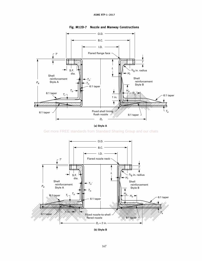
ASME RTP-1–2017
Fig. M12D-7 Nozzle and Manway Constructions
Dr + 2 in.
1 in.
6:1 taper
6:1 taper1 in.
6:1 taper
Dr
6:1 taper
Flued nozzle-to-shell flared nozzle
Flued shell lining flush nozzle
6:1 taper
6:1 taper
Shell reinforcement Style A
S.F. dia.
Shell reinforcement Style B
Shell reinforcement Style B
Flared nozzle neck
O.D.
(a) Style A
(b) Style B
B.C.
I.D.
Flared flange face
O.D.
B.C.
I.D.
3/8 in. radius
Ho
Ts
Ts
Ho
HoHo
Hr
Tn'
Tn
Pe
ToTr
6:1 taper
6:1 taper
Shell reinforcement Style APe
Tr
T
L
3/8 in. radiusHr
T
L
T'
S.F. dia.
T'
6:1 taper
Tn'Tn
To
6:1 taper
167
Get more FREE standards from Standard Sharing Group and our chats

ASME RTP-1–2017
Fig. M12D-8 Bottom Nozzle Constructions
6:1 taper
6:1 taper
6:1 taper
6:1 taper
6:1 taperVortex breaker (optional)
6:1 taper
6:1 taperS.F. dia.
Shell reinforcement Style A
Shell reinforcement Style B
Shell reinforcement Style B
6:1 taper
1 in.
1 in.
1 in.
1 in.
1 in.
S.F. dia.
O.D.
I.D. O.D.
B.C.
B.C.
I.D.
3/8 in. radius
3/8 in. radius
Ho
Pe
Hr
HoHo
Ts
Tr
T
To
Pe
T'
Tr
T'
L
TnTn'
To
Ts
Tr To
Ho
Ho Hr
L
Tn
Tn'
T
Ho
Ts
Dr + 2 in.
Dr + 2 in.
GENERAL NOTE: Special consideration is to be made to address the cantilever, pump, and vortex forces.
168
ASME RTP-1–2017
weld with the spark tester is impossible. This testingrequires appropriate conductive targets to be installedbehind welds. In cases where there is access to the insideof the vessel, spark testing can be accomplished afterinstalling the target and before the remainder of the RTPoverlay is applied.
(d) The RTP structural overlay may be applied to thenozzle/manway neck and flange before attachment tothe shell or end closure. Alternatively, if the lining canbe supported suitably, the RTP structural overlay may beapplied after weld attachment of these appurtenances.
M12D-700 INTERNAL ATTACHMENTS
(a) Internal attachments include baffles, dip pipes,spargers, and others. Since these are ordinarily sup-ported by attachment to the thermoplastic lining, specialcare in design and fabrication is necessary to ensurethat lining forces and lining-to-RTP bond forces are lowenough to avoid failure (see para. M12C-400).
(b) In case an attachment must be installed over ashell weld or an end closure weld, the weld overbeadwill be mechanically removed before installing theattachment. A preferred alternative approach for bafflesand some other attachments is to cut out the attachmentlocally to accommodate the weld overbead.
(c) Reinforcement pads are required for all attach-ments to the liner. A small drain hole may be providedon the bottom of each pad. For applications involvingsanitary conditions, such as food or pure water, thisdrain hole will not be installed.
M12D-800 REPAIR PROCEDURES
M12D-810 Scope
This section sets forth general criteria and repair pro-cedures that are to be used to correct nonconformitiesin liners in dual laminate vessels before they may beaccepted as complying with this Standard. Where repairinvolves removal and replacement of any of the RTPstructural laminate, the procedures of MandatoryAppendix M-7 will also apply.
M12D-820 General Conditions
In general, when the nonconformities in the defectiveor damaged liner, bond, or related RTP laminate arerepaired, the repair will ensure that the final area willhave the same physical strength and chemical resistanceas the specified original laminate. All defects and com-pleted repairs must be recorded in writing in a repairlog, which will become part of the quality assurancedocuments for that vessel. Other general conditions out-lined in Mandatory Appendix M-7 appropriate to duallaminate repairs also apply.
169
M12D-830 Nonconformities
Vessels fabricated to this Standard may be repairedto correct nonconformities prior to certification andstamping, provided that all the following conditionsare met:
(a) The general requirements of para. M7-210 as theyapply to repair of dual laminates are met.
(b) The thermoplastic manufacturer’s procedures andlimitations on rewelding are followed.
(c) The nonconformities must be classified as repair-able as indicated in para. M12D-840.
(d) The Fabricator will provide detailed written pro-cedures for each kind of repair that will be made.
(e) The total amount of area repaired by patching orreplacing lining after the RTP has been applied will notexceed 2% of the total inside liner area or 3 ft2, whicheveris greater.
(f) The total length of weld joints that are repairedafter the RTP overlay is applied will not exceed 2% ofthe total length of welds in the thermoplastic liner. Allwelds can be replaced prior to application of the RTPoverlay.
(g) Weld repairs are accomplished by a qualifiedWelder qualified on the same material as the liner andin accordance with the Fabricator’s qualification proce-dures and with this Standard.
M12D-840 Repairable Nonconformities
Repairable nonconformities are(a) all weld defects in Table M12D-1.(b) debonded areas.(c) blisters.(d) incorrect location of nozzles only when the correct
nozzle is relocated far enough away so that reinforcingpads do not overlap.
(e) liner surface nonconformities contained inTable M12B-4. Scratches may be polished or scraped out,except that the thickness of the sheet will not becometoo thin (see Table M12B-4).
(f) stress relief not accomplished when required.(g) weld defects detected in the final inspection by
high voltage spark test when the vessel has less than1% of total weld length plus 12 in.
M12D-850 Irreparable Nonconformities
The following nonconformities will not be consideredrepairable. A vessel that has any one of these nonconfor-mities will not be certified as being fabricated in accor-dance with this Standard.
(a) Incorrect material: sheet, filler rod, strip, etc.(b) Weld defects detected during final inspection by
high voltage spark test that exceed the following:(1) 2% of total weld length plus 12 in. prior to
hydrotest(2) 1% of total weld length plus 12 in. after
hydrotest (rehydrotest not required)
Get more FREE standards from Standard Sharing Group and our chats

ASME RTP-1–2017
(c) Liner is thinner than lower tolerance on thickness.(d) Thermoformed components are less than specified
thickness.(e) Ground strip for spark test target omitted or insuf-
ficiently conductive.
M12D-900 APPLICATION OF THE RTP OVERLAY
M12D-910 Application of Spark Test Targets
Prior to application of the RTP overlay, all of the con-ductive spark test targets must be applied. As a mini-mum, all welds will have a conductive target on theexterior surface of the liner prior to application of theRTP overlay (see para. M12D-500).
M12D-920 Testing Bond Strength Between Liner andRTP Overlay
Before fabrication starts, the Fabricator will ensureadequate bond strength by performing the tests requiredin para. M12B-614.4. In addition, for dual laminate ves-sels with PVC or CPVC liners, these tests will be per-formed on each bonding resin batch and on each lot ofsheet material used. The bond strength test results willbe documented and will meet the minimum require-ments of para. M12B-614.4.
M12D-1000 INSPECTION
In addition to the requirements of Article E, theInspector will visually check the interior and exteriorsurfaces of the lining before the RTP overlay is appliedand the exterior surface of the RTP overlay after it isapplied. All the visual requirements of Tables M12D-1and M12E-1 will be met. In particular, this inspectionwill ensure that cap strips and conductive targets areinstalled properly (see para. M12E-220).
ARTICLE EINSPECTION AND TEST
M12E-100 SCOPE
This Article covers inspections and tests required ona dual laminate vessel. It is intended to ensure that thecompleted vessel has been designed and fabricated inaccordance with the requirements of the latest revisionsof the design, of the approved drawings, of the UBRS,and of this Standard.
This Article is in addition to the inspection and testingof the RTP structural laminate of dual laminate vesselswhich is provided in Part 6 of this Standard. However,some inspections and tests of the lining, the bond, andthe RTP laminate should or may be accomplished at thesame time.
When the corrosion barrier of the RTP laminate isreplaced by a thermoplastic lining, the testing for quality
170
of the lining as provided in this Article will replace thoserequirements for the corrosion barrier in Part 6.
M12E-200 FINAL INSPECTION
(a) In addition to the documents the Fabricator isrequired to provide the Inspector in accordance withpara. 6-900(a), the following documents related to duallaminate inspection will be provided:
(1) Welder qualification records for individualWelders who made welds in the vessel
(2) current weld map and sheet placement(3) high voltage spark test records(4) material logs for all materials used
(b) Paragraphs M12E-210 and M12E-220 describe theminimum basic tests relating to the thermoplastic liningthat must be made, witnessed, or reviewed by theInspector prior to or at the time of the final inspection.
M12E-210 High Voltage Spark Test
The Inspector will witness the last high voltage sparktest performed. This last test will normally be after thehydrotest. Any spark test indication of a defect will because for rejection until the defect is repaired andretested with satisfactory results.
M12E-220 Lining Imperfections: Visual Inspection
(a) During fabrication, the Fabricator will make allchecks necessary to ensure that the lining and the lining–RTP bond meet the requirements of this Standard, partic-ularly the requirements of Tables M12B-4, M12D-1, andM12E-1. The Fabricator’s Quality Control Program willinclude procedures and forms to be used to control theongoing process of lining fabrication and lining–RTPbond fabrication so as to ensure that imperfections arewithin required tolerances prior to final inspection.
(b) The Inspector will visually check interior surfacesof the lining and the exterior surface of the RTP overlay.The Inspector will ensure that all visual requirementsof Tables M12B-4 and M12E-1 are met.
(c) The final visual inspection will be made after thelast high voltage spark test, the hydrotest, and the acous-tic emission (if used) tests are completed.
(d) As provided in para. 6-940(e), the Inspector willrecord the results of the visual inspection in the inspec-tion report.
ARTICLE FSHIPPING AND HANDLING
M12F-100 SCOPE
This Article covers special requirements for shippingand handling dual laminate vessels at low temperatures.

ASME RTP-1–2017
Table M12E-1 Lining Visual Inspection Acceptance Criteria
Imperfection Definition of Imperfection Allowed Comments
Omission of cap strip Omission when required Not acceptable Repairable only before applicationof RTP structure
Cracks Linear ruptures of the lining None See Note (1)Debonding Lack of bond between lining and None See Note (1)
RTP structure
Foreign inclusions Particles in the lining that are not None See Note (1)of the plastic composition
Dents, pits, grooves Surface irregularities in the lining Maximum depth 10% of See Note (1)sheet thickness, maximumsize 1⁄8 in. diameter or1 in. long
Blisters (internal) Pores within plastic sheet None See Note (1)
NOTE:(1) These imperfections may be repaired if approved by the Inspector and the Fabricator’s Quality Assurance Manager, and written proce-
dures are received and approved.
M12F-200 PRECAUTIONS TO PREVENTMECHANICAL DAMAGE
(a) Since many of the thermoplastics used for linersare brittle and become more sensitive to mechanicalshock as temperatures decrease, precautions must betaken in handling and storing to ensure that impact orhigh stresses are avoided. In particular, polypropylene,PVC, CPVC, and PVDF homopolymer should beshipped and stored above 32°F (0°C). Special precau-tions to avoid mechanical shock are required, especiallyif ambient temperatures are below these limits.
(b) Thermal stresses due to sudden changes in tem-perature will be avoided, as these can cause cracking ofthe thermoplastic liner. An example is moving a vesselfrom a heated area to the outside in cold weather.
M12F-300 INSPECTION AFTER SHIPMENT ANDINSTALLATION
When a vessel arrives at the User’s facility and beforeunloading from the transport vehicle, a visual inspection(internal and external) is recommended to detect anydamage that may have occurred during shipping. Afterinstallation of a vessel at the User’s facility, a high volt-age spark test is recommended to detect any defectsin the liner that may have occurred during shipping,handling, and installation.
ARTICLE GSHOP QUALIFICATION
M12G-100 SCOPE
This Article covers requirements a Fabricator willmeet in order to qualify capability for fabricating duallaminate vessels in accordance with this Standard. Theserequirements are in addition to those set forth in Part 7.
171
M12G-200 GENERAL
In addition to the requirements of para. 7-210 for theshop survey, the ASME survey team will verify that therequirements of this Article are met.
M12G-300 FABRICATOR’S FACILITIES ANDEQUIPMENT
In addition to the facilities specified in para. 7-300,the following facilities and equipment will be availablefor qualification during the shop survey:
(a) areas designated for storage of plastic sheet, weldrod, and other plastic shapes
(b) areas designated for storage of semifinished com-ponents of dual laminate vessels
(c) separate shop fabrication areas for assemblingthermoplastic liners with special provisions for control-ling dust, proper ventilation, cleanliness, andtemperature
(d) equipment for thermoplastic welding includingappropriate gas supply [see paras. M12D-421(g) and (h)]
(e) temperature-measuring instruments capable ofmeasuring welding and thermoforming temperatureswith accuracy of ±2°C
(f) equipment for thermoforming plastic sections ofvessels including flaring and fluing for nozzle attach-ment [see para. 7-300(b)]
(g) laboratory equipment for evaluation of welds inaccordance with para. M12H-400, except that tensile testservices may be obtained from a qualified outsidelaboratory
(h) inspection equipment for determining the qualityof welds, including high voltage spark tester
(i) equipment (internal or at an external facility) fordetermining the bond strength between the thermoplas-tic liner and the RTP overlay (see para. M12B-614.4)
Get more FREE standards from Standard Sharing Group and our chats
(17)
(17)
ASME RTP-1–2017
M12G-400 PERSONNEL
The Fabricator’s organization shall include specificpersonnel designated and qualified for the followingfunctions:
(a) welding thermoplastic parts, and training andevaluating Welders (see Article H).
(b) designing thermoplastic lined vessels, includingknowledge of the technology of welding thermoplastics.As authorized in para. 7-400, for RTP vessels this func-tion may be performed by outside qualified engineeringdesign personnel.
M12G-500 DEMONSTRATION OF CAPABILITY
M12G-510 Welding Capability
Each Fabricator’s shop shall demonstrate the abilityto fabricate thermoplastic liners, including welding, torequired quality levels. A Welder qualification record(see para. M12H-100) shall be maintained showingWelder capability to weld thermoplastic parts. The rec-ords shall clearly show qualification records for all thefollowing:
(a) type of welding; i.e., hot gas butt welding, nozzle-to-shell welding, cap strip welding, etc.
(b) specific thermoplastic material(c) specific Welder’s name(d) certification for each separate combination of (a),
(b), and (c)
M12G-520 Bonding Capability
Each Fabricator’s shop shall demonstrate capabilityto bond the RTP overlay to thermoplastic liners withsufficient strength to satisfy the requirements ofpara. M12B-614.4. The shop survey team shall verifybond strength test records and shall determine that theFabricator has the equipment and trained personnel todetermine bond strength.
M12G-530 Demonstration Vessel
(a) The Fabricator shall produce a demonstration ves-sel, which shall be inspected by the ASME shop surveyteam. For the purposes of this qualification demonstra-tion vessel, the lining system shall be divided into thefollowing lining classes:
Lining Demonstration DemonstrationClassification Vessel Top Half Vessel Bottom Half
A [Note (1)] Fabric bonded lining Chemically bonded liningB [Note (2)] Fabric bonded lining Fabric bonded liningC [Note (3)] Chemically bonded Chemically bonded lining
liningNOTES:(1) Fabric and chemically bonded thermoplastic linings.(2) Fabric bonded thermoplastic linings only.(3) Chemically bonded thermoplastic linings only.
A Fabricator selects the appropriate lining classificationand builds a demonstration vessel accordingly. The
172
Fabricator is restricted to fabricating vessels to thisStandard in only that class of lined vessels for whichhe/she has built a demonstration vessel that has passedthe qualification procedure.
(b) The demonstration vessel shall be fabricatedaccording to Fig. M12G-1 and Table M12G-1.
(c) A Fabricator who is not certified to fabricate solidRTP vessels may qualify for a restricted certificate fordual laminate vessels only.
M12G-531 Demonstration Vessel QualityRequirements
(a) The demonstration vessel shall be inspected by theASME shop survey team and shall meet the followingrequirements:
(1) The vessel shall meet all visual inspectionrequirements of this Mandatory Appendix.
(2) The layout of thermoplastic sheets and the weldmap shall conform to the requirements ofpara. M12C-300.
(3) The vessel shall be tested to full vacuum. Nodebonding of the lining will be evident.
(4) The vessel shall be high voltage spark testedand will not show any defects.
(5) The demonstration vessel shall be cross-sectioned in accordance with Fig. M12G-2 to show theweld quality, the amount of liner thinning in thermo-formed knuckles and flares for nozzles, flange construc-tion and quality, bond between the liner and the RTPoverlay, and the spark test targets. All of these areasshall meet the requirements of this Appendix.
(b) Failure to meet any of the requirements in(a) above shall cause the Fabricator to fail for qualifica-tion to fabricate to ASME standards that class of duallaminate vessel.
(c) The vessel shall be sectioned and placed on perma-nent display in the same manner as the RTP vessel.
M12G-540 Procedures
The Fabricator shall have the following proceduresclearly defined and established:
(a) spark testing(b) welding(c) forming(d) safety(e) stress relieving
M12G-550 Fabricator Certification
A Fabricator shall be certified to fabricate only duallaminate vessels by constructing one demonstrationvessel in accordance with Fig. M12G-1. The followingconditions shall be met:
(a) The hydrotest required in MandatoryAppendix M-6 is performed before the vacuum testrequired in M12G-531(a)(3).

ASME RTP-1–2017
Fig. M12G-1 Dual Laminate Demonstration Vessel
2 in. nozzle C
45 deg
C FRP support legs, equally spaced
Type I laminate
Type II laminate
2 ft
, 6 in
.
1 ft
, 11 /
2 in
.
2 ft
, 3 in
.
2 ft
, 9 in
.
3 ft
, 4 in
.
Type II or filament wound laminate
FRP pipe leg supports; four required, equally spaced
2 in. nozzle B
ASME flanged and dished head or 2:1 elliptical head
ASME flanged and dished head or 2:1 elliptical head
2 in. x 2 in. integral support ledge
Tangent line
Tangent line
Integral body flange
Gusset
Affix nameplate to bracket located in this general area
65 deg
3 in. tangential nozzle A
I.D. 42 in. min., 54 in. max.
GENERAL NOTES:(a) Laminate thicknesses are to be based on design pressure and temperature, and laminates are to be of the type specified here (see
UBRS).(b) Each head shall have a weld seam with a length exceeding the tank radius.
173
Get more FREE standards from Standard Sharing Group and our chats

ASME RTP-1–2017
Table M12G-1 User’s Basic Requirements Specification (UBRS)(As Required by the Provisions of ASME RTP-1)
Page 1 of 4
RTP Edition No.
UBRS Revision No.
User firm name Not applicable
User’s Agent firm name Not applicable
Title of equipment ASME RTP-1 dual laminate demonstration vessel
User’s designation no. ASME RTP-1 �1
Installation location (name and address) Fabricator’s shop
UBRS prepared by (User or User’s Agent):
Name Mandatory Appendix M-12, ASME RTP-1 Phone no. Not applicable Date
Address
1. Equipment description (equipment sketch and nozzle schedule shall be attached):
2. Additional Fabricator responsibilities:
[x] Special requirements
[ ] Acoustic emission testing
[x] Inspection or testing requirements not listed in the Standard Special, fully flooded (all air vented), ambient
temp. water, proof hydrotest at 44 psig to 46 psig max.
[x] Full vacuum after hydrotest is complete
[x] Spark test after vacuum test
[x] Visual inspection acceptance level (refer to Table 6-1 of ASME RTP-1):
[x] Level 1
[ ] Level 2
Quantity limitations for gaseous air bubbles or blisters
174

ASME RTP-1–2017
Table M12G-1 User’s Basic Requirements Specification (UBRS) (Cont’d)(As Required by the Provisions of ASME RTP-1)
Page 2 of 4RTP Edition No.
UBRS Revision No.
[ ] Additional inspection aids/methods [refer to para. 6-940(c) of ASME RTP-1]
3. Material selection
3.1 Material selection by:
[ ] Resin manufacturer (include data per section 4 of this document)
[ ] Fabricator (include data per section 4 of this document)
[ ] End User. Applicable User’s specifications/standards, codes, ordinances, FDA requirements, etc. (list and specify; attach
copies of local code/ordinance requirements)
[x] Other As required by Mandatory Appendix M-12
3.2 Material of construction:
Resin Catalyst/cure system CoNap/MEKP
Veil Barcol hardness per para. 6-910(b)(4)
[ ] Lift lugs: [ ] RTP [ ] Carbon steel [ ] Other
[ ] Hold-down lugs: [ ] RTP [ ] Carbon steel [ ] Other
4. Chemical service data (shall be provided when Fabricator or resin manufacturer is making material selection)
4.1 Description of process function and process sequence: Not applicable
4.2 Contents:
Concentration
Chemical Name Max. % Min. % Exposure Time
Potable water 100 100 Continuous
4.3 pH range: max. min.
5. Design
5.1 Design conditions:
Operating Design
Internal pressure 14 psig 15 psig
External pressure 0.0 psig Full vacuum
Temperature 80°F 140°F
Specific gravity 1.0 1.0
Liquid level Full Full
175
Get more FREE standards from Standard Sharing Group and our chats
ASME RTP-1–2017
Table M12G-1 User’s Basic Requirements Specification (UBRS) (Cont’d)(As Required by the Provisions of ASME RTP-1)
Page 3 of 4
RTP Edition No.
UBRS Revision No.
Wind/seismic/snow code (include edition or year) ASCE 7
Basic wind speed 0 MPH Classification category Exposure
Elevation above grade ft Topographic factors
Seismic zone 1 Site-specific seismic information (soil type, ground motion coefficients,
etc.)
Snow load 0 psf
Capacities: Operating Flooded gal Flooded By Fabricator gal
5.2 Mechanical agitator: [ ] Required [ ] Not required
Dead load lb
Static bending moment ft-lb
Dynamic bending moment ft-lb
Torque ft-lb
Horsepower hp
Impeller speed RPM Impeller diameter in.
Number of impellers Foot bearing: [ ] Yes [ ] No
5.3 Heating and cooling:
[ ] Electric panels
[ ] Steam coil
[ ] Steam sparger
[ ] Heat exchanger
[ ] Other
5.4 Mechanical and other forces:
[ ] Violent chemical reaction
[ ] Subsurface introduction of gas or vapor
[ ] Subsurface introduction of steam
[ ] Transmitted mechanical load/force
[ ] Impact due to introduction of solids
[ ] Vacuum from pump down (or vessel draining)
[ ] Vacuum from cool down
[x] Other Not applicable
5.5 Corrosion barrier excluded from structural calculations:
[x] Yes
[ ] No
5.6 Declaration of critical service (only by User or User’s Agent; refer to para. 1-210 of ASME RTP-1):
[ ] Yes
[x] No
6. Designation of Inspector (Review paras. 1-400, 1-430, and 1-440 of ASME RTP-1. It shall be recognized that ASME RTP-1
establishes numerous duties for the Inspector, which necessitates that the Inspector be present in the fabrication shop throughout
a major portion of the fabrication interval.). Inspector shall be:
[x] Fabricator’s Quality Control principal
[ ] User’s representative
[ ] Other
176

ASME RTP-1–2017
Table M12G-1 User’s Basic Requirements Specification (UBRS) (Cont’d)(As Required by the Provisions of ASME RTP-1)
Page 4 of 4
RTP Edition No.
UBRS Revision No.
Inspector’s name Telephone
Company
Address
6.1 Approval of Inspector designation
6.1.1 Authorized User’s representative:
Name Title
Signature Date
6.1.2 Authorized Fabricator’s representative:
Name Title
Signature Date
Additional requirements: Requires Witness of Hydrotest form (Fig. M6-3).
Approach maximum hydrotest pressure using a manually actuated hydrotest pump, in a number of pressure steps, over a
30-min time period.
Provide a substantial physical barrier between the vessel and all personnel during hydrotest for safety reasons.
GENERAL NOTE: This form may be reproduced and used without written permission from ASME if used for purposes other than republication.
177
Get more FREE standards from Standard Sharing Group and our chats

ASME RTP-1–2017
Fig. M12G-2 Post-Test Sectioning of Dual Laminate Demonstration Vessel for Final Inspection and Display
Section above gusset
Cut lines30 deg
178

(17)
ASME RTP-1–2017
(b) The visual requirements of the liner(Table M12E-1) are substituted for the visual require-ments of the RTP liner.
(c) The RTP structural overlay of the dual laminatevessel is in complete accordance with requirements ofthis Standard.
ARTICLE HQUALIFICATION OF WELDERS
M12H-100 GENERAL REQUIREMENTS
(a) This Article specifies the rules for qualifying per-sonnel to weld thermoplastic parts together. Thermo-plastic linings will be assembled only by personnel whohave been qualified in accordance with the requirementsof this Article.
(b) A Welder is an individual who joins thermoplasticparts together using fusion bonding processes.
(c) The Fabricator will maintain up-to-date recordsrelating to qualification of each Welder. These recordswill document the date of last qualification, and willinclude all calculations and test or inspection reportsfrom internal and independent laboratory testing pro-grams used in the process of qualification. These recordsare subject to review on request by all parties engagedin the process of procurement or inspection.
M12H-200 RESPONSIBILITY
It is the responsibility of the Fabricator to train andqualify thermoplastic Welders. Safety is also the respon-sibility of the Fabricator [see para. M12D-421(l)].
M12H-300 QUALIFICATION OF WELDERS
(a) Welders may qualify their capabilities at the timea Fabricator qualifies for shop qualification underArticle G.
(b) Welder and welding operator performance quali-fications shall be in accordance with AWS B2.4. Thequality of polymeric weld joints depends on the qualifi-cation of the Welders and welding operators, the suit-ability of the equipment used, environmental influences,and adherence to the applicable Welding ProcedureSpecification (WPS). Welders and welding operatorsshall be trained and possess a valid qualificationcertificate.
(c) It is the responsibility of the Fabricator’s QualityControl Manager to
(1) document the Welding Procedure Specification(WPS) and Performance Qualification Test Record(PQTR) as outlined in AWS B2.4 for the preparation,machining, and testing of welder and welding operatorqualification samples
(2) supervise or conduct the visual inspection ofwelds made for qualification in accordance withAWS G1.10M
179
(3) verify that weld samples are tested in accor-dance with AWS B2.4
(4) sign and date the certification process PQTR(d) Welders shall qualify separately for each thermo-
plastic material (TPM) and for each weld process perAWS B2.4.
M12H-310 Making Weld Test Samples
M12H-311 Butt Welds(a) Welds shall be made in accordance with AWS B2.4.
In addition to the requirements of AWS B2.4, whereapplicable, each weld sample shall contain a weld startand a weld stop.
(b) For hot gas welds, a single V-shaped bevel shallbe used for all sheet thicknesses under 0.160 in. (4 mm)thick and a double V bevel shall be used for all thick-nesses 0.160 in. (4 mm) and greater. The Welder shallbe responsible for the generation of the appropriate bev-els. For welding TFE, the weld rod shall be PFA.
M12H-312 Cap Strip Welds. Cap strip welds shallbe made over existing welds. Cap strips with or withoutfiber backing may be used. The crown of the existingweld shall be appropriately skived or ground off beforethe cap strip weld is applied.
M12H-313 Nozzle Welds. The Welder shall preparethe nozzle and the flat or curved part representing theshell of the vessel. Two nozzles shall be welded, one2 in. in diameter and another 4 in. to 8 in. in diameter.Thicknesses shall represent those thicknesses expectedfor that material. If pipe is used, the pipe wall thicknesswill be in the range expected to be used. Evaluationshall be by visual inspection only. The nozzles shall becut in half to aid in visual inspection.
M12H-400 EVALUATING WELD SAMPLES
(a) Visual inspection of all welds shall be accom-plished by an experienced Welder qualified in the mate-rial and weld process being evaluated in accordancewith AWS G1.10M. Each weld evaluator shall be desig-nated in writing by the Fabricator’s Quality ControlManager. This document shall contain the period duringwhich the assignment as weld evaluator will be valid,as well as any limits on the type or kind of evaluationfor each evaluator.
(b) The visual weld inspector shall fill out the PQTRfor all visual factors listed that are appropriate to theweld process under evaluation per AWS G1.10M.
(c) Each and all individual tensile test or bend testresults shall meet the criteria as required in AWS B2.4.Results of the tests shall be recorded on the PQTR. Inaddition to AWS B2.4 Table 4.3, see Table M12H-1 foradditional short term weld factors.
(d) Welds shall be qualified in accordance withAWS B2.4. A WPS and PQTR shall be provided for each
(17)
(17)
(17)
(17)
Get more FREE standards from Standard Sharing Group and our chats

(17)
(17)
(17)
ASME RTP-1–2017
Table M12H-1 Weld Strength Requirements
Short Term Minimum Weld Factor
Thermoplastic Flow Hot Plate Butt Flow Fusion
PP 0.9 0.9PVC 0.9 NACPVC 0.8 NAPVDF 0.9 0.9
ECTFE 0.9 0.9FEP 0.9 0.9TFE (PFA filler) NA NAPFA 0.9 0.9
polymer and process being used. Environmental condi-tion recommendations shall be included in the WPS.
M12H-500 REQUALIFICATION
Requalification shall be for each TPM and each weldprocess. In any case, Welders shall requalify at leastevery year. If a Welder has not made a weld using thatspecific material and process in the past 6 months, he/she is required to requalify prior to making welds onlinings under this Standard.
M12H-600 WELDING PROCEDURE QUALIFICATION
Welding procedures shall be qualified in accordancewith AWS B2.4. A WPS shall be provided for each poly-mer and process being used. Environmental conditionrecommendations shall be included in the WPS.
ARTICLE IGLOSSARY
acoustic emission test: a technique for finding flaws inmaterials by using transducers to detect the soundenergy emitted when flaws grow under an intentionallyapplied stress.
annealing: heat treatment after processing to removeinternal stresses incurred during fabrication processes.
backing: a fibrous component, either woven or nonwo-ven, embedded into a thermoplastic lining to allow amechanical bond between the lining and the structurallaminate; usually a knit woven product.
backing strip: a thin strip of plastic of the same materialas the base plastic sheet fused to the back of fusionwelds, often used to replace the fiber to assist bondingthat was removed in order to accomplish the weld.
bridging: a weld defect in which the weld bead does notfill the prepared groove between two pieces of thermo-plastic to be welded.
180
butt fusion weld: a weld accomplished by heating the twosurfaces to be joined, then forcing the surfaces togetherto accomplish a fusion weld.
cap strip: a thin strip of plastic of the same material asthe base plastic sheet liner that is heat welded over fusionwelds. When the cap strip is applied on the backside ofa weld, it contains fiber embedding to ensure continuityof bonding where fiber had been intentionally removedto facilitate welding.
climbing drum test: a test to determine the bond strengthof a lining on a structural material by using a rollingdrum debonding action (ASTM D1781).
CPVC: chlorinated polyvinylchloride.
crown: that part of a hot gas fusion weld that standsabove the surfaces of the base plastic sheets.
CTFE: chlorotrifluoroethylene.
dual laminate: a two-ply laminate consisting of a chemi-cally resistant thermoplastic liner bonded to an RTPstructural laminate.
ECTFE: ethylene chlorotrifluoroethylene.
environmental stress crack: stress cracking requiring a spe-cific environment or atmosphere in order to cause thecrack to occur. See stress crack.
etching: a surface effect that results in a roughened sur-face from chemical reaction.
extrusion weld: a weld formed between two thermoplas-tic materials by a hot thermoplastic strip extruded intothe weld joint at a temperature high enough to form afusion bond.
face tensile test: a tensile test to determine the bondstrength of a lining on a structural material by pullingthe bond apart using only tensile forces (ISO 14130).
FEP: fluorinated ethylene propylene.
flaring: a shaping process in which the end of a cylinderis thermoformed (flared) over a pattern to form aflanged end.
flow lines: the melted material that flows out, formingsmall extrusions on both sides of the weld bead.
fluing: a shaping process in which a flat, or nearly flat,sheet is pierced with a round tool to generate a holewith a neck in the sheet.
ground: a material on the back of a weld (or any otherpart of a thermoplastic liner) that has sufficient electricconductivity to allow high voltage spark testing to detectflaws in the weld.
ground strip: a ground in the form of a strip placed againstor bonded onto the back of weld bead.
HDPE: high density polyethylene.
heat-affected zone (HAZ): the areas adjacent to both sidesof the completed weld bead that became heated duringwelding and became shiny in appearance.

ASME RTP-1–2017
hot air weld: a fusion weld normally made by hand inwhich the base thermoplastic and filler rod are heatedby hot air.
hot gas weld: a fusion weld made by hand in which thebase thermoplastic and filler rod are heated by a hot gas.
hot plate weld: see butt fusion weld.
lap shear test: a shear test to determine the bond strengthbetween a thermoplastic lining and the RTP structurallaminate.
MFA: methylfluoroalkoxy fluoropolymer.
notch: see undercut.
orange peel: an irregularity in surface topology that visu-ally resembles an orange peel.
overbead: see crown.
PE: polyethylene.
peel strength test: a test that peels the lining off of a duallaminate composed of a thermoplastic lining and anFRP structural laminate to determine the bond strength.Three such tests are the climbing drum test(ASTM D1781), the peel test (BS 4994), and the floatingroller peel test (ASTM D3167).
PFA: Teflon® PFA or perfluoroalkoxy fluoropolymer.
PP: polypropylene.
PTFE: see TFE.
purge material: a different thermoplastic, such as PP, usedto clean out remaining weld filler material from a weldtool, such as an extruder, to prevent difficulty in continu-ing welding after cooling the tool.
PVC: polyvinylchloride.
PVDF: polyvinylidene fluoride.
spark test: a high voltage test for detecting flaws in plasticby emitting a loud crack sound when a spark passesthrough a flaw in the plastic to the conductive groundor target.
speed welding: a hand fusion weld process where thefiller rod is fed to the weld using hand force through atube to the weld bead; this process is more efficient andrapid than hand welding, where the filler rod is heldseparately in one hand.
stress crack: an external or internal rupture in a plasticcaused by tensile stresses less than its short-timemechanical strength.
181
stress relief: a heat treatment given(a) to received materials before fabrication to remove
residual internal stresses incurred during thermoplasticprocessing steps or
(b) to welded parts to remove or reduce internalstresses from fabrication steps such as welding orthermoforming
surface contamination: any undesired foreign materialadhering to the surfaces of material used in the fabrica-tion of dual laminate products. Examples are lubricantsand other processing aids; dirt, oil, and foreign matterfrom the environment; residual adhesive from protectivefilms; solvent and any other cleaning residues; etc.
target: conductive material behind a weld or behind theliner itself that becomes a ground for high voltage sparktesting.
TFE: tetrafluoroethylene; also used to indicate PTFE,polytetrafluoroethylene.
thermal cycle test: a test using ten thermal cycles to qualifythe bond strength; no debonding indicates satisfactorybond strength. The temperature extremes are usuallyboiling water and a dry-ice–acetone bath (−78°C).
thermoforming: a process for shaping sheet material bydeforming at elevated temperature to allow shapingwith low forces and less danger of cracking.
undercut: a groove in a weld extending below the surfaceof the base thermoplastic sheets and usually located atthe edge of the weld bead.
virgin material: material (sheet, rod, or strip) that hasbeen manufactured from new, not recycled, plastic andthat has not been used earlier in any other service.
weld bead: the material in the weld comprised of plasticfrom the applied welding rod and melted plastic fromthe base sheet material.
weld factor: the average tensile strength of welded sam-ples divided by the average tensile strength of theunwelded sheet material. The resulting number is oftenexpressed in percent. Short term weld factor is a weldfactor from tensile strength tests done in a short time,i.e., minutes. Long term weld factor is a weld factor basedon tensile creep strength of weld samples compared tounwelded sheet material.
welding: a process for joining by using heat or other formof energy to fuse together two pieces of material.
Get more FREE standards from Standard Sharing Group and our chats

ASME RTP-1–2017
MANDATORY APPENDIX M-13BALSA WOOD RECEIVING AND INSPECTION PROCEDURES
M13-100 INTRODUCTIONAll inspections and tests specified in this Appendix
are to be performed by Fabricator personnel or an inde-pendent laboratory. This Appendix specifies the mini-mum inspections and tests that shall be performed onbalsa wood that shall be used to fabricate equipment tothis Standard.
M13-200 ACCEPTANCE INSPECTION(a) Acceptance inspection shall include inspection of
all boxes for proper packaging and identification, andcontamination. This acceptance inspection is to be con-ducted on unopened boxes. Acceptance requirementsand limits are as defined in para. M13-410.
(b) The form in Table M13-1, or a similar form thatcontains the provisions to record the results of theserequired inspections, shall be used by the Fabricator.
(c) In addition to performing the above inspectionsand documentation, the Fabricator shall provide theUser or User’s agent with a Certificate of Compliancefrom the material manufacturer. The Certificate shallensure that materials were manufactured, inspected, andtested per the material supplier’s specifications.
M13-300 EQUIPMENT AND MEASURING TOOLSREQUIRED
A moisture meter as described in ASTM D4444 isrequired. The meter shall be capable of reading a rangeof 6% to 18% moisture content.
M13-400 PROCEDURES AND ACCEPTANCE LIMITSM13-410 Balsa Wood Identification and Package
InspectionThe balsa wood shall be stored in the packaging as
shipped from the balsa wood manufacturer’s factory. If
182
repackaging is required, the Fabricator shall ensure thata material Certificate of Compliance traceable to theoriginal material is provided. All other documentationshall remain unchanged. Verify and enter on the inspec-tion record that the balsa wood as identified by the balsawood manufacturer has the same nomenclature as thebalsa wood specified to produce the laminate. Indicateacceptable balsa wood by recording the date and nameof the person performing the examination onTable M13-1, column 4.
M13-420 Visual Inspection Criteria
(a) As balsa wood is used during fabrication, it shallbe visually inspected for imperfections and contamina-tion. Date and name of the person performing the visualinspection shall be recorded on Table M13-1, column 6.
(b) The balsa wood should be uniform in thicknessand show no visible sign of curling due to excessivemoisture.
(c) Prior to bedding the balsa wood into the innerlaminate layer, the moisture content shall be measuredand recorded on Table M13-1, column 5. The moisturecontent shall also be measured prior to applying theouter laminate layers and recorded on Table M13-1,column 5.
(d) Measurement methods shall be as recommendedby the balsa wood core manufacturer or ASTM D4444.
(e) Balsa wood having any of the following defectsshall not be used in laminates built to this Standard:
(1) wet spots(2) contamination(3) moisture content above 14%

ASME RTP-1–2017
Table M13-1 Balsa Wood Core Inspection Sheet
Fabricator’s name Balsa wood manufacturer
Address Balsa wood core type
Balsa wood core nomenclature
QC file no.
� Receiving inspection
� Point of use inspection
1 2 3 4 5 6 7 8
Package Balsa Wood Lot. No. Packaging Moisture Content Visual Laminate Adhesion CommentsNo. Production Date [Note (1)] Inspection Inspection Inspection Check
(if Given) By Date By Date By Date By Date
1
2
3
4
5
6
7
8
9
10
11
12
13
14
15
16
17
18
19
20
GENERAL NOTE: This form may be reproduced and used without written permission from ASME if used for purposes other than republication.
NOTE:(1) Lot, pallet, product code, or other label identification.
183
Get more FREE standards from Standard Sharing Group and our chats

ASME RTP-1–2017
NONMANDATORY APPENDIX NM-1DESIGN EXAMPLES
NM1-100 INTRODUCTION
The RTP-1 Standard provides for design by rules(Subpart 3A) and for design by stress analysis(Subpart 3B). This Appendix presents two exampledesigns, one by Subpart 3B rules, and one by combinedSubparts 3A and 3B rules. They are intended to illustratePart 3 and are correct applications of the Standard butare not the only designs satisfying the requirements. Theexamples are
(a) a vertical vessel, with a torispherical top head anda toriconical lower head, made of Type I laminate anddesigned by combined Subparts 3A and 3B rules
(b) a horizontal, saddle-supported vessel, with tori-spherical heads, made of Type I laminate and designedby Subpart 3B rules
NM1-200 EXAMPLE 1: VERTICAL VESSEL WITH ATORICONICAL LOWER HEAD
The UBRS calls for a vessel 8 ft in diameter, 15 ft fromlower to upper knuckle, and with a conical lower headhaving a semiapex angle of 45 deg. The vessel mustcontain an internal pressure of 10 psi and be made ofType I laminate. The support ring will be 10 ft abovethe lower knuckle. The upper part of the sidewall andthe top head may be designed according to Subpart 3Arules, but the lower head has a larger semiapex anglethan allowed by Subpart 3A. The lower part of the side-wall and the lower head must therefore be designed bystress analysis, using Subpart 3B rules. The Fabricatorhas qualified Type I laminates for an ultimate tensilestrength of 12,000 psi. According to para. 3B-500, theminimum allowable stress ratio is 10; thus, the allowablestress is 1,200 psi.
For analysis, the vessel may be cut 8 ft above the cone–cylinder joint, because the section is out of both thediscontinuity zone of the lower head-to-shell joint andthe stress intensification near the support ring, and istherefore in a simple membrane stress state. The stressthere has no secondary membrane and no bendingstress, providing a convenient section to begin theSubpart 3B analysis. It is assumed that the sectionededge has no axial displacement, but no other constraint,which is consistent with a membrane stress state in acylinder. The UBRS calls for a 4 in. diameter nozzle atthe apex of the cone. The rules of Part 4 may be usedto design the nozzle and its attachment, so for purposesof analysis, a free edge is left at the lower end of the
184
head. To minimize stress intensification at the head–shell juncture, a toroidal transition is used. Figure NM1-1is a sketch of the resulting model. The numbers in smallrectangles are meridional distances from the bottom ofthe head to the points indicated.
As a trial design, Subpart 3A rules were used to findthe thickness of the sidewall
t pPD
2(X/R)
p(10)(96)
(2)(12,000/10)
p 0.40 in.
and of the lower head
t pPD
2(X/R) cos �
p(10)(96)
(2)(12,000/10) cos (45 deg)
p 0.57 in.
At 0.043 in. per mat ply and 0.01 in. for a veil, thethicknesses are rounded up slightly so that they corre-spond to an even number of plies. The head laminateis then V, 13M for a thickness of 0.57 in., and the sidewalllaminate is V, 10M, or 0.44 in. thick. As an initial try,the joint overlay was set equal to the thickness of thehead, and extends full thickness 1.5 in. above and belowthe toroidal knuckle and then tapers.
The vessel was modeled using a finite difference thin-shell computer program. The program computes thestresses required by paras. 3B-300 and 3B-400 and com-bines them into the longitudinal and circumferentialstresses on the inside and outside of the vessel wall,all along a meridian. Let �1 represent the longitudinalnormal stress on the inside surface and �2 representthe circumferential normal stress. Because the vessel,loading, and support forces are axisymmetric, the shearstresses vanish. Paragraph M3-530 gives the criterionfor Type I laminates
R pX
(�21 − �1�2 + �2
2 + 3�26)
1⁄2

ASME RTP-1–2017
Fig. NM1-1 Toriconical Head
0.0
62.67
67.19
163.19
Conical head design per Subpart 3B
45 deg
Cylindrical shell design per Subpart 3A
96DIA
5.76RAD
185
Get more FREE standards from Standard Sharing Group and our chats

ASME RTP-1–2017
In the present case, R p 10, X p 12,000 psi, and�6 p 0. Therefore
XR
p (�21 − �1�2 + �2
2)1⁄2 p
12,00010
p 1,200 psi
This is the criterion for the inside surface of the lowerpart of the vessel. The criterion for the outer has thesame form. The term under the square root, the stressintensity, was plotted as a function of the meridionaldistance and compared to the allowable stress. The ini-tial design was overstressed in the knuckle. A seconddesign with a joint overlay twice the thickness of thefirst was tried. Figure NM1-2 is a graph of stress intensityversus meridional distance for the second design. Thedashed horizontal line is at 1,200 psi, the allowable stress.The figure shows that all stresses satisfy the criterionand that the design conforms to the Standard.Table NM1-1 lists the thicknesses and laminations of thesuccessful design as a function of meridional distancefrom the bottom of the vessel.
As the example shows, a vessel that lies outside therules of Subpart 3A because one vessel part is notincluded may use Subpart 3A rules for most of the vesseland Subpart 3B for the excluded part.
NM1-300 EXAMPLE 2: HORIZONTAL VESSEL BYSUBPART 3B RULES
The UBRS calls for a horizontal vessel with 10 ft insidediameter, 20 ft between head–shell junctures, and sup-port saddles 2 ft in from the junctures and 18 in. wide.The heads will be torispherical, with the crown radiusequal to the vessel diameter, and the knuckle radiusequal to 6% of the vessel diameter. The vessel will con-tain liquid with a specific gravity of 1.1 with a superim-posed design pressure of 15 psig. The vessel will beconstructed of Type I laminate with ultimate tensilestrength of 16,000 psi. The vessel will be examined usingacoustic emission according to the requirements ofMandatory Appendix M-8, and thus, the allowable stressratio, by para. 3B-500, is eight. Figure NM1-3 containsa sketch of the vessel.
Nomenclature used in this example is as follows:p p total pressure acting at a point on the inside
surface of the vessel, positive outward, psips p pressure exerted by the support saddle, posi-
tive outward, psip0 p pressure superimposed above the hydrostatic
pressure, psiR p radius to a point on the surface, in.
Rc p radius of the cylindrical portion of the ves-sel, in.
Rh p crown radius, in.Rk p knuckle radius, in.Rs p stress ratioS p stress intensity, psi
186
w p weight of the vessel and its contents, lbX p ultimate strength, psi� p specific weight of the contents, lb/in.3
� p circumferential angle, measured from the topmeridian of the vessel, deg
�z p normal stress in the meridional direction, psi�� p normal stress in the circumferential direction,
psi� p angle between a normal to a point on the head
and the vessel axis, deg� p shear stress in the plane of the laminate, psi
NM1-310 Loading on the Vessel
The combined hydrostatic and design pressure at apoint on the surface of the vessel is given by
p p p0 + �(Rc − R cos �) (1)
See Fig. NM1-4. The radius to a point on the cylinderis simply Rc and the pressure on the cylindrical vesselparts not under the support saddle is given by
p p p0 + �Rc(1 − cos �) (2)
The radius to a point on the crown is
R p Rh sin � (3)
and to a point on the knuckle is
R p Rc − Rk + Rk sin � p Rc − Rk(1 − sin �) (4)
Thus, the pressures on the crown and the knuckle arecomputed from eqs. (5) and (6) below, respectively
p p p0 + �(Rc − Rh sin � cos �) (5)
p p p0 + �{Rc − [Rc − Rk(1 − sin �)] cos �} (6)
The saddle supports are modeled by replacing themwith the pressure they exert against their contact areaon the vessel shell. It is assumed that the reaction pres-sure from the saddle varies as cos � on the lower halfof the shell and is zero on the upper half. It is shownin Fig. NM1-5 that for equilibrium the variation is
ps pw
�RcLcos � (7a)
for 90 deg ≤ � ≤ 270 deg, and
ps p 0 (7b)
for 0 ≤ � ≤ 90 deg and 270 deg ≤ � ≤ 360 deg.Note that eqs. (7a) and (7b) give negative values, since
the saddle pressure is inward. Thus, the net pressure onthe portion of the shell between 24 in. and 42 in. from
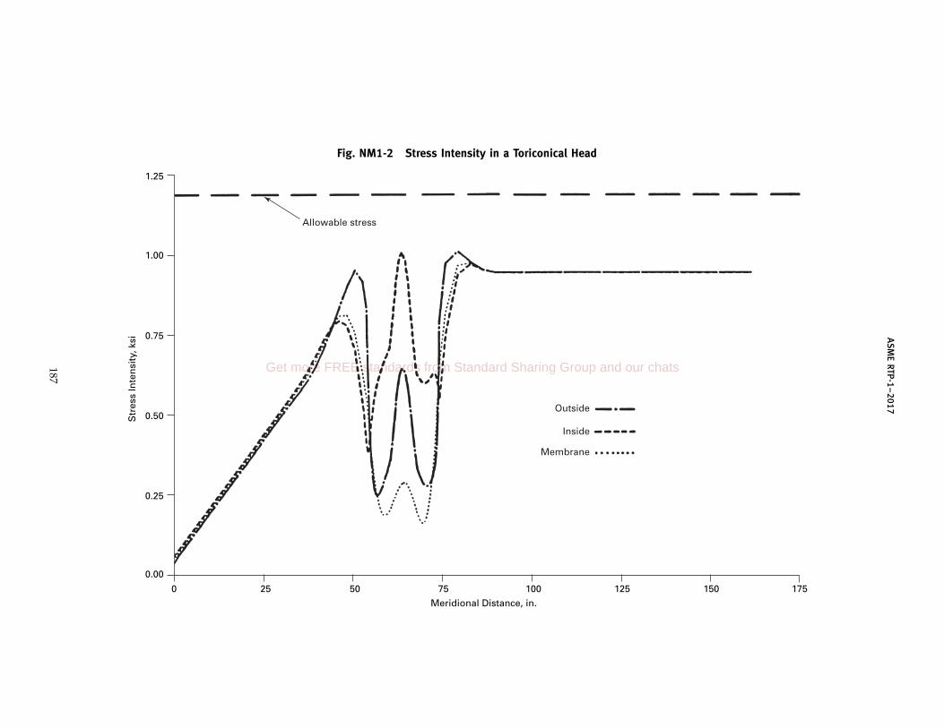
AS
ME
RTP-1–2017
Fig. NM1-2 Stress Intensity in a Toriconical Head
0.00
1.25
1.00
0.75
0.50
0.25
Str
ess
Inte
nsi
ty, k
si
0 25 50 75 100 125 150 175
Meridional Distance, in.
Allowable stress
Outside
Inside
Membrane
187
Get more FREE standards from Standard Sharing Group and our chats
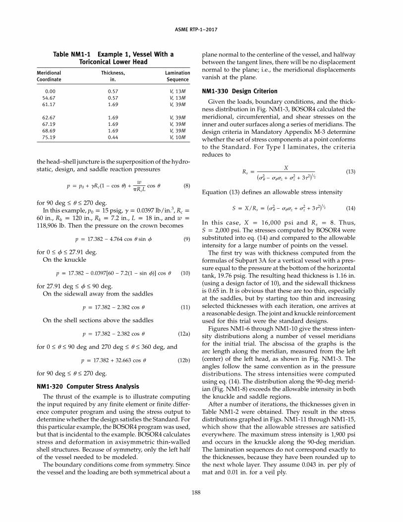
ASME RTP-1–2017
Table NM1-1 Example 1, Vessel With aToriconical Lower Head
Meridional Thickness, LaminationCoordinate in. Sequence
0.00 0.57 V, 13M54.67 0.57 V, 13M61.17 1.69 V, 39M
62.67 1.69 V, 39M67.19 1.69 V, 39M68.69 1.69 V, 39M75.19 0.44 V, 10M
the head–shell juncture is the superposition of the hydro-static, design, and saddle reaction pressures
p p p0 + �Rc(1 − cos �) +w
�RcLcos � (8)
for 90 deg ≤ � ≤ 270 deg.In this example, p0 p 15 psig, � p 0.0397 lb/in.3, Rc p
60 in., Rh p 120 in., Rk p 7.2 in., L p 18 in., and w p118,906 lb. Then the pressure on the crown becomes
p p 17.382 − 4.764 cos � sin � (9)
for 0 ≤ � ≤ 27.91 deg.On the knuckle
p p 17.382 − 0.0397[60 − 7.2(1 − sin �)] cos � (10)
for 27.91 deg ≤ � ≤ 90 deg.On the sidewall away from the saddles
p p 17.382 − 2.382 cos � (11)
On the shell sections above the saddles
p p 17.382 − 2.382 cos � (12a)
for 0 ≤ � ≤ 90 deg and 270 deg ≤ � ≤ 360 deg, and
p p 17.382 + 32.663 cos � (12b)
for 90 deg ≤ � ≤ 270 deg.
NM1-320 Computer Stress Analysis
The thrust of the example is to illustrate computingthe input required by any finite element or finite differ-ence computer program and using the stress output todetermine whether the design satisfies the Standard. Forthis particular example, the BOSOR4 program was used,but that is incidental to the example. BOSOR4 calculatesstress and deformation in axisymmetric thin-walledshell structures. Because of symmetry, only the left halfof the vessel needed to be modeled.
The boundary conditions come from symmetry. Sincethe vessel and the loading are both symmetrical about a
188
plane normal to the centerline of the vessel, and halfwaybetween the tangent lines, there will be no displacementnormal to the plane; i.e., the meridional displacementsvanish at the plane.
NM1-330 Design Criterion
Given the loads, boundary conditions, and the thick-ness distribution in Fig. NM1-3, BOSOR4 calculated themeridional, circumferential, and shear stresses on theinner and outer surfaces along a series of meridians. Thedesign criteria in Mandatory Appendix M-3 determinewhether the set of stress components at a point conformsto the Standard. For Type I laminates, the criteriareduces to
Rs pX
��2� − ���z + �2
z + 3�2�1⁄2(13)
Equation (13) defines an allowable stress intensity
S p X/Rs p ��2� − ���z + �2
z + 3�2�1⁄2 (14)
In this case, X p 16,000 psi and Rs p 8. Thus,S p 2,000 psi. The stresses computed by BOSOR4 weresubstituted into eq. (14) and compared to the allowableintensity for a large number of points on the vessel.
The first try was with thickness computed from theformulas of Subpart 3A for a vertical vessel with a pres-sure equal to the pressure at the bottom of the horizontaltank, 19.76 psig. The resulting head thickness is 1.16 in.(using a design factor of 10), and the sidewall thicknessis 0.65 in. It is obvious that these are too thin, especiallyat the saddles, but by starting too thin and increasingselected thicknesses with each iteration, one arrives ata reasonable design. The joint and knuckle reinforcementused for this trial were the standard designs.
Figures NM1-6 through NM1-10 give the stress inten-sity distributions along a number of vessel meridiansfor the initial trial. The abscissa of the graphs is thearc length along the meridian, measured from the left(center) of the left head, as shown in Fig. NM1-3. Theangles follow the same convention as in the pressuredistributions. The stress intensities were computedusing eq. (14). The distribution along the 90-deg merid-ian (Fig. NM1-8) exceeds the allowable intensity in boththe knuckle and saddle regions.
After a number of iterations, the thicknesses given inTable NM1-2 were obtained. They result in the stressdistributions graphed in Figs. NM1-11 through NM1-15,which show that the allowable stresses are satisfiedeverywhere. The maximum stress intensity is 1,900 psiand occurs in the knuckle along the 90-deg meridian.The lamination sequences do not correspond exactly tothe thicknesses, because they have been rounded up tothe next whole layer. They assume 0.043 in. per ply ofmat and 0.01 in. for a veil ply.

AS
ME
RTP-1–2017
Fig. NM1-3 Horizontal Tank
0.0
186.
26
108.
26
90.2
6
66.2
6
58.45
33 in.
120DIA
7.2RAD
120RAD
C L
180-deg saddle
189
Get more FREE standards from Standard Sharing Group and our chats

ASME RTP-1–2017
Fig. NM1-4 Pressure Distribution
Rc
Rh
Rk
RR cos
R = Rh sin
Rk sin
Rc − Rk
p = po + h = po + (Rc − R cos )
h
φ φ
Rc − Rk + Rk sin
θθ
θγγ
φ
φ
φ
GENERAL NOTES:(a) On the sidewall, R = Rc and p = po + Rc (1 − cos )(b) On the crown, R = Rh sin and p = po + (Rc − Rh sin cos ) (c) On the knuckle, R = Rc − Rk + Rk sin and p = po + {Rc − [Rc −Rk (1 − sin )] cos }γ
θγ
γθ
φφ
φφ θ
190

ASME RTP-1–2017
Fig. NM1-5 Saddle Reaction
dF = kR cos d
dF cos
dF cos = kLRF = L cos2 d
dF
Ps( )
θ
d
Saddle pressure
= k cos for − ≤ ≤ = 0 elsewhere
3 2 2
3 2
2
2
W2
Upward reaction from the saddle is given by
cos2 d =
cos
but F = and
W2
k LR2
Then =
W RL
W RL
and k = ; Ps =
3 2
2
3 2
2
θ
θ θ
θ θ
θ
θ
π π
π
θ θ θ
θ θ
θ
π π
π
ππ
π
π
π
π
191
Get more FREE standards from Standard Sharing Group and our chats

AS
ME
RTP-1–2017
Fig. NM1-6 Stress Along Top Meridian, Initial Try
0.0
2.5
2.0
1.5
1.0
0.5
Str
ess
Inte
nsi
ty, k
si
0 25 50 75 100 125 150 175 200
Meridional Distance, in.
Outside
Inside
Membrane
192
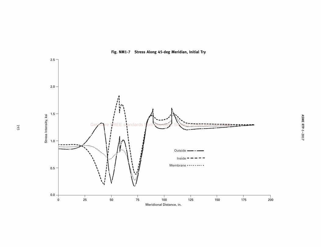
AS
ME
RTP-1–2017
Fig. NM1-7 Stress Along 45-deg Meridian, Initial Try
0.0
2.5
2.0
1.5
1.0
0.5
Str
ess
Inte
nsi
ty, k
si
0 25 50 75 100 125 150 175 200
Meridional Distance, in.
Outside
Inside
Membrane
193
Get more FREE standards from Standard Sharing Group and our chats
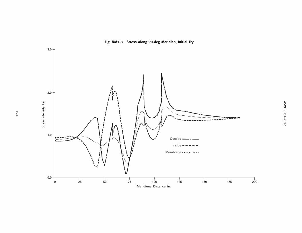
AS
ME
RTP-1–2017
Fig. NM1-8 Stress Along 90-deg Meridian, Initial Try
0.0
3.0
2.0
1.0
Str
ess
Inte
nsi
ty, k
si
0 25 50 75 100 125 150 175 200
Meridional Distance, in.
Outside
Inside
Membrane
194
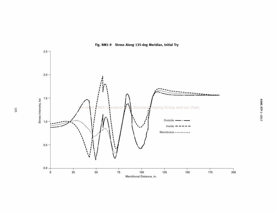
AS
ME
RTP-1–2017
Fig. NM1-9 Stress Along 135-deg Meridian, Initial Try
0.0
2.5
2.0
1.5
1.0
0.5
Str
ess
Inte
nsi
ty, k
si
0 25 50 75 100 125 150 175 200
Meridional Distance, in.
Outside
Inside
Membrane
195
Get more FREE standards from Standard Sharing Group and our chats

AS
ME
RTP-1–2017
Fig. NM1-10 Stress Along Bottom Meridian, Initial Try
0.0
2.5
2.0
1.5
1.0
0.5
Str
ess
Inte
nsi
ty, k
si
0 25 50 75 100 125 150 175 200
Meridional Distance, in.
Outside
Inside
Membrane
196

ASME RTP-1–2017
Table NM1-2 Wall Thickness in a Horizontal Tank
Meridional Thickness, LaminationCoordinate in. Sequence
0.00 1.16 V, 27M43.45 1.16 V, 27M58.45 2.60 V, 61M66.26 2.60 V, 61M
90.26 1.30 V, 30M108.26 1.30 V, 30M116.26 0.65 V, 15M186.26 0.65 V, 15M
197
Get more FREE standards from Standard Sharing Group and our chats
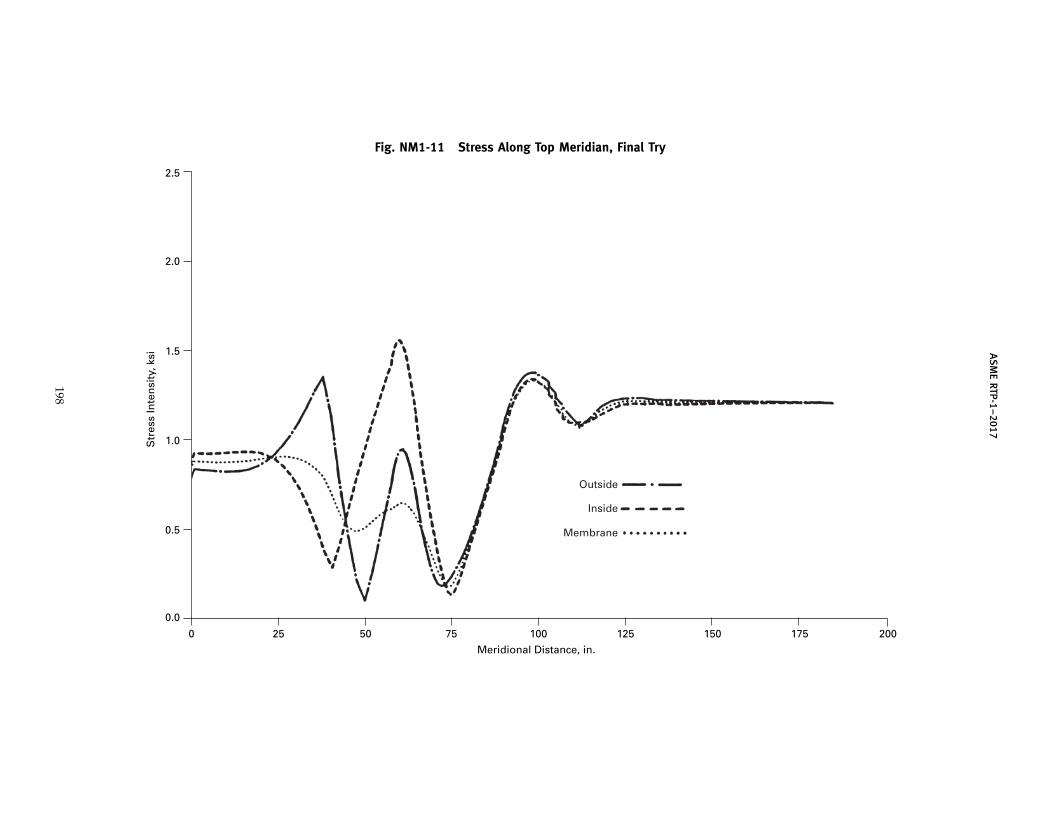
AS
ME
RTP-1–2017
Fig. NM1-11 Stress Along Top Meridian, Final Try
0.0
2.5
2.0
1.5
1.0
0.5
Str
ess
Inte
nsi
ty, k
si
0 25 50 75 100 125 150 175 200
Meridional Distance, in.
Outside
Inside
Membrane
198

AS
ME
RTP-1–2017
Fig. NM1-12 Stress Along 45-deg Meridian, Final Try
0.0
2.5
2.0
1.5
1.0
0.5
Str
ess
Inte
nsi
ty, k
si
0 25 50 75 100 125 150 175 200
Meridional Distance, in.
Outside
Inside
Membrane
199
Get more FREE standards from Standard Sharing Group and our chats

AS
ME
RTP-1–2017
Fig. NM1-13 Stress Along 90-deg Meridian, Final Try
0.0
2.5
2.0
1.5
1.0
0.5
Str
ess
Inte
nsi
ty, k
si
0 25 50 75 100 125 150 175 200
Meridional Distance, in.
Outside
Inside
Membrane
200

AS
ME
RTP-1–2017
Fig. NM1-14 Stress Along 135-deg Meridian, Final Try
0.0
2.5
2.0
1.5
1.0
0.5
Str
ess
Inte
nsi
ty, k
si
0 25 50 75 100 125 150 175 200
Meridional Distance, in.
Outside
Inside
Membrane
201
Get more FREE standards from Standard Sharing Group and our chats

AS
ME
RTP-1–2017
Fig. NM1-15 Stress Along Bottom Meridian, Final Try
0.0
2.5
2.0
1.5
1.0
0.5
Str
ess
Inte
nsi
ty, k
si
0 25 50 75 100 125 150 175 200
Meridional Distance, in.
Outside
Inside
Membrane
202
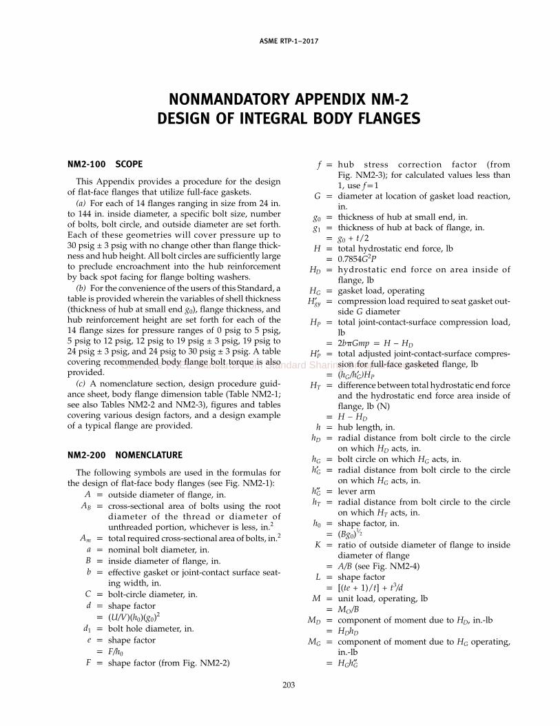
ASME RTP-1–2017
NONMANDATORY APPENDIX NM-2DESIGN OF INTEGRAL BODY FLANGES
NM2-100 SCOPE
This Appendix provides a procedure for the designof flat-face flanges that utilize full-face gaskets.
(a) For each of 14 flanges ranging in size from 24 in.to 144 in. inside diameter, a specific bolt size, numberof bolts, bolt circle, and outside diameter are set forth.Each of these geometries will cover pressure up to30 psig ± 3 psig with no change other than flange thick-ness and hub height. All bolt circles are sufficiently largeto preclude encroachment into the hub reinforcementby back spot facing for flange bolting washers.
(b) For the convenience of the users of this Standard, atable is provided wherein the variables of shell thickness(thickness of hub at small end g0), flange thickness, andhub reinforcement height are set forth for each of the14 flange sizes for pressure ranges of 0 psig to 5 psig,5 psig to 12 psig, 12 psig to 19 psig ± 3 psig, 19 psig to24 psig ± 3 psig, and 24 psig to 30 psig ± 3 psig. A tablecovering recommended body flange bolt torque is alsoprovided.
(c) A nomenclature section, design procedure guid-ance sheet, body flange dimension table (Table NM2-1;see also Tables NM2-2 and NM2-3), figures and tablescovering various design factors, and a design exampleof a typical flange are provided.
NM2-200 NOMENCLATURE
The following symbols are used in the formulas forthe design of flat-face body flanges (see Fig. NM2-1):
A p outside diameter of flange, in.AB p cross-sectional area of bolts using the root
diameter of the thread or diameter ofunthreaded portion, whichever is less, in.2
Am p total required cross-sectional area of bolts, in.2
a p nominal bolt diameter, in.B p inside diameter of flange, in.b p effective gasket or joint-contact surface seat-
ing width, in.C p bolt-circle diameter, in.d p shape factor
p (U/V)(h0)(g0)2
d1 p bolt hole diameter, in.e p shape factor
p F/h0
F p shape factor (from Fig. NM2-2)
203
f p hub stress correction factor (fromFig. NM2-3); for calculated values less than1, use fp1
G p diameter at location of gasket load reaction,in.
g0 p thickness of hub at small end, in.g1 p thickness of hub at back of flange, in.
p g0 + t/2H p total hydrostatic end force, lb
p 0.7854G2PHD p hydrostatic end force on area inside of
flange, lbHG p gasket load, operatingH′gy p compression load required to seat gasket out-
side G diameterHP p total joint-contact-surface compression load,
lbp 2b�Gmp p H − HD
H′P p total adjusted joint-contact-surface compres-sion for full-face gasketed flange, lb
p (hG/h′G)HPHT p difference between total hydrostatic end force
and the hydrostatic end force area inside offlange, lb (N)
p H − HDh p hub length, in.
hD p radial distance from bolt circle to the circleon which HD acts, in.
hG p bolt circle on which HG acts, in.h′G p radial distance from bolt circle to the circle
on which HG acts, in.h″G p lever armhT p radial distance from bolt circle to the circle
on which HT acts, in.h0 p shape factor, in.
p (Bg0)1⁄2
K p ratio of outside diameter of flange to insidediameter of flange
p A/B (see Fig. NM2-4)L p shape factor
p [(te + 1)/t] + t3/dM p unit load, operating, lb
p MO/BMD p component of moment due to HD, in.-lb
p HDhD
MG p component of moment due to HG operating,in.-lb
p HGh″G
Get more FREE standards from Standard Sharing Group and our chats

AS
ME
RTP-1–2017
Table NM2-1 Typical Body Flange Dimensions and Recommended Bolt Torque Values for RTP Body Flanges
Minimum Inside Minimum Outside Bolt Circle Design Pressure Bolt Hole Design Pressure Bolt Hole Number TorqueDiameter, B, Diameter, A, Diameter, C, in. 5–20 psi Diameter, in. 25–30 psi Diameter, in. of Required,
in. in. [Notes (1), (2)] Bolt Size, in. [Note (3)] Bolt Size, in. [Note (3)] Bolts ft-lb
24 291⁄2 28 1⁄25⁄8
1⁄25⁄8 20 9
30 351⁄2 34 1⁄25⁄8
1⁄25⁄8 28 12
36 411⁄2 40 1⁄25⁄8
1⁄25⁄8 32 13
42 471⁄2 46 1⁄25⁄8
1⁄25⁄8 40 14
48 54 521⁄21⁄2
5⁄81⁄2
5⁄8 44 1654 60 581⁄2
1⁄25⁄8
1⁄25⁄8 48 18
60 66 641⁄21⁄2
5⁄81⁄2
5⁄8 52 1872 781⁄2 77 1⁄2
5⁄85⁄8
3⁄4 64 2184 91 891⁄2
1⁄25⁄8
5⁄83⁄4 76 25
96 1041⁄2 1021⁄25⁄8
3⁄43⁄4
7⁄8 84 35108 117 115 5⁄8
3⁄43⁄4
7⁄8 96 39120 1291⁄2 1271⁄2
5⁄83⁄4
3⁄47⁄8 104 45
132 142 140 5⁄83⁄4
3⁄47⁄8 116 46
144 155 1521⁄23⁄4
7⁄87⁄8 1 120 62
GENERAL NOTES:(a) The above torque values were calculated using well lubricated low alloy carbon steel bolts.(b) For flanges having surface irregularities and requiring higher torque values to effect sealing, torques can be increased to 25 ft-lb for 1⁄2 in. diameter bolts, 50 ft-lb for 5⁄8 in.
diameter bolts, and 83 ft-lb for 3⁄4 in. diameter bolts without incurring flange damage.(c) Lower torques can be used for lower pressure applications.(d) These dimensions were used in designing the flanges shown in Table NM2-2. Alternate flange geometries can be considered using the design method illustrated in this
Appendix. Also, see Table NM2-3.
NOTES:(1) ± 0.06 in. (ASME B16.5).(2) ± 0.06 in. eccentricity between bolt circle and center of shell.(3) ± 0.03 in. center to center of adjacent bolt holes (ASME B16.5).
204

AS
ME
RTP-1–2017
Table NM2-2 Body Flange Design Using Full-Face Gaskets,Maximum Stress Less Than 3,000 psi — Type II Laminates
Nominal Flange Diameter
Criterion 24 30 36 42 48 54 60 72 84 96 108 120 132 144
P 5 5 5 5 5 5 5 5 5 5 5 5 5 5t 0.5 0.5 0.5 0.5 0.625 0.688 0.813 1.063 1.25 1.563 1.813 2.125 2.438 2.375g 0.25 0.25 0.25 0.25 0.25 0.25 0.25 0.25 0.25 0.25 0.25 0.25 0.313 0.313
P 10 10 10 10 10 10 10 10 10 10 10 10 10 10t 0.5 0.563 0.625 0.75 0.938 1.0 1.0 1.25 1.375 1.625 1.875 2.0 2.125 2.375g 0.25 0.25 0.25 0.25 0.25 0.25 0.313 0.313 0.375 0.438 0.375 0.438 0.5 0.5
P 15 15 15 15 15 15 15 15 15 15 15 15 15 15t 0.625 0.688 0.813 0.938 1.0 1.125 1.125 1.25 1.438 1.688 1.875 2.0 2.188 2.5g 0.25 0.25 0.25 0.25 0.375 0.375 0.375 0.375 0.438 0.5 0.563 0.625 0.813 0.75
P 20 20 20 20 20 20 20 20 20 20 20 20 20 20t 0.75 0.813 0.875 0.938 1.0 1.063 1.125 1.25 1.438 1.625 1.813 2.0 2.125 2.5g 0.25 0.313 0.313 0.375 0.375 0.375 0.438 0.5 0.563 0.688 0.75 0.813 0.875 1.0
P 25 25 25 25 25 25 25 25 25 25 25 25 25 25t 0.813 0.875 0.938 1.0 1.125 1.188 1.188 1.375 1.563 1.813 1.938 2.125 2.313 2.438g 0.313 0.313 0.375 0.375 0.5 0.5 0.5 0.625 0.75 0.813 0.875 1.0 1.125 1.25
P 30 30 30 30 30 30 30 30 30 30 30 30 30 30t 0.875 0.938 1.0 1.063 1.375 1.25 1.313 1.438 1.625 1.938 2.125 2.313 2.438 2.625g 0.313 0.375 0.375 0.5 0.5 0.563 0.625 0.75 0.875 1.0 1.125 1.25 1.375 1.438
GENERAL NOTES:(a) Flange design based on the following criteria:
P p allowable pressure, psit p flange thickness, in.
g p thickness of hub at end of taper (pipe thickness), in. — Type II laminate propertiesh p hub length, in. p 3t
m p gasket factor (assumed m p 0.5)Y p gasket unit seating load (assumed Y p 50 psi)
maximum flange and hub stress p 3,000 psi (based on use of mat/woven roving reinforcement, Type II laminate)maximum bolt stress p 18,800 psimaximum design temperature p 180°F
(b) This Table is referenced in Table NM2-1.
205
Get more FREE standards from Standard Sharing Group and our chats

AS
ME
RTP-1–2017
Table NM2-3 Body Flange Design Using Full-Face Gaskets,Maximum Stress Less Than 1,800 psi — Type I Laminates
Nominal Flange Diameter
Criterion 24 30 36 42 48 54 60 72 84 96 108 120 132 144
P 5 5 5 5 5 5 5 5 5 5 5 5 5 5t 0.625 0.625 0.625 0.688 0.875 0.938 1.063 1.313 1.438 1.75 2.0 2.125 2.25 2.5g 0.25 0.25 0.25 0.25 0.25 0.25 0.25 0.25 0.25 0.313 0.313 0.375 0.375 0.438
P 10 10 10 10 10 10 10 10 10 10 10 10 10 10t 0.625 0.75 0.875 0.938 1.0 1.063 1.125 1.313 1.5 1.813 1.938 2.0 2.313 2.375g 0.25 0.25 0.25 0.25 0.313 0.313 0.375 0.438 0.5 0.563 0.625 0.75 0.75 0.875
P 15 15 15 15 15 15 15 15 15 15 15 15 15 15t 0.813 0.875 0.938 1.0 1.125 1.188 1.25 1.375 1.563 1.813 1.938 2.125 2.313 2.438g 0.25 0.313 0.375 0.375 0.438 0.5 0.5 0.625 0.75 0.813 0.938 1.0 1.125 1.25
P 20 20 20 20 20 20 20 20 20 20 20 20 20 20t 0.938 1.0 1.0 1.125 1.25 1.313 1.375 1.5 1.688 2.0 2.188 2.375 2.563 2.75g 0.313 0.375 0.438 0.5 0.563 0.625 0.688 0.813 1.0 1.125 1.25 1.375 1.5 1.625
P 25 25 25 25 25 25 *25 *25 *25 *25 *25 *25 *25 *25t 1.063 1.063 1.125 1.188 1.375 1.375 1.438 1.625 1.813 2.125 2.313 2.563 2.75 2.875g 0.375 0.438 0.5 0.625 0.688 0.75 0.875 1.0 1.188 1.375 1.5 1.688 1.875 2.0
P 30 30 30 30 30 30 *30 *30 *30 *30 *30 *30 *30 *30t 1.063 1.125 1.188 1.25 1.438 1.5 1.563 1.75 1.938 2.25 2.438 2.625 2.875 3.063g 0.438 0.5 0.625 0.75 0.813 0.938 1.0 1.25 1.313 1.625 1.813 2.0 2.25 2.438
GENERAL NOTES:(a) Flange design based on the following criteria:
P p allowable pressure, psit p flange thickness, in.
g p thickness of hub at end of taper (pipe thickness), in. — Type I laminate propertiesh p hub length, in. p 3t
m p gasket factor (assumed m p 0.5)Y p gasket unit seating load (assumed Y p 50 psi)
maximum flange and hub stress p 1,800 psi (based on use of mat reinforcement, Type I laminate)maximum bolt stress p 18,800 psimaximum design temperature p 180°F
(b) Sizes preceded by an asterisk should be used with SAE steel washers to minimize interference with the hub.(c) This Table is referenced in Table NM2-1.
206

ASME RTP-1–2017
Fig. NM2-1 Design of Flat-Face Integral Body Flanges With Full-Face Gaskets
Design of Flat-Face Integral Body Flanges With Full-Face Gaskets
Design Conditions Bolting Calculations
Design pressure, P p psi LeverhG p
C−B4
p in. h′G pA−C
4p in.
armsDesign temperature, T p °F
Atmos. temperature, T p °F G p C − 2hG p in. b p 0.25(C − B) p in.
Flange material: H′gy p (hG/h′G) (b�Gy) p lb
Bolting material: Wm2 p b�Gy + H′gy p lb
Gasket material: Hp p 2b�GmP p lb
DesignFlange Sfo p psi H ′p p Hp (hG/h′G) p lbtemp.
Allowable DesignStresses Sb p psi H p 0.7854G2P p lbtemp.
BoltingAtmos.
Sa p psi Wm1 p H + Hp + H ′p p lbtemp.
Gasket Factors Am p greater ofWm2
Saor
Wm1
Sbp in.2
y p AB p in.2psi m p
W p 0.5(Am + AB)Sa p lb
Flange Loads Lever Arms Flange Moments (Design Cond.)
HD p 0.7854B2P p lb hD p R + 0.5g1 p in. MD p HDhD p in.-lb
HT p H − HD p lb hT p 0.5(R + g1 + hG) p in. MT p HThT p in.-lb
MO p MD + MT p in.-lb
Reverse HG p W − H p lb h′′G p
hGh ′GhG + h′G
p in. MG p HGh′′G p in.-lb
moment
AllowableStress Calculations Shape Constants
Stress
Long hub SH p fM/Lg21 p psiSfo p K p A/B p
Sfo p Radial flg. SR p N1M/Lt2 p psi T p Z p Y p U p
Sfo p Tang. flg. ST p (YM/t2) − ZSR p psi g1/g0 p
h0 p (Bg0)1⁄2 p
Sfo p Greater of 0.5(SH + SR) or 0.5(SH + ST) p psih/h0 p
Radial stress at bolt circle F p
Sfo p V pSRAD p6MG
t2(�C − nd1)p psi
f p (1 min.)
dia. bolts
(n) bolts
Slope 1:3 max.
(d1) holes
g0 =
B =
g1 = (g1 = t/2 + g0)
H ′G
h ′G
hG
hD
HD
hTHG
A =
C =
h = R =
G =
t
e p F/h0 p
d pUV
h0g20 p
M p MO /B p
Approximation of required thickness
t p 0.29�MYSfo �
1⁄2
p in.
N1 p 4⁄3 te + 1 p
L pte + 1
T+
t3
dp
GENERAL NOTE: This form may be reproduced and used without written permission from ASME if used for purposes other than republication.
207
Get more FREE standards from Standard Sharing Group and our chats

ASME RTP-1–2017
Fig. NM2-2 Values of F (Integral Flange Factors)
0.5
F
1 1.5 g1/g0 = 1.96
h/h0 = 0.612
g1/g0
0.6
0.7
0.8F = 0.808
0.9
0.908920
2.5
0.10
3 3.5 4 4.5 52
0.200.250.300.350.40
0.450.50
0.60
0.70
0.80
0.90
1.00
1.25
1.502.00
hh0
hBg0
=
208

ASME RTP-1–2017
Fig. NM2-3 Values of f (Hub Stress Correction Factors)
25
20
15
10
98
7
6
5
4
3
2.5
2
1.5
1
6
5
4
3
2.5
2
1.5
11 1.5 2 3 4 5
f < 1.0; therefore, the minimum value f = 1.0 shall be used
g1/g0 = 1.96h/h0 = 0.612
g1/g0
hh 0
hBg 0
=
f = 1 (minimum)f = 1 for hubs of uniform thickness (g1/g0 = 1)f = 1 for loose hubbed flanges
0
0.05
0.10
0.15
0.20
0.25
0.30
0.35
0.40
0.45
0.50
0.60
0.70
0.80
0.90
1.00
1.10
1.20
1.30
f
209
Get more FREE standards from Standard Sharing Group and our chats

ASME RTP-1–2017
Fig. NM2-4 Values of T, U, Y, and Z (Terms Involving K)
1
1.02
5
4
3
10
20
8
6
2
1
5
4
3
10
8
6
2
T, U
, Y, a
nd
Z
30
40
5060
80
1001.03 1.05 1.10
1.02 1.03 1.05 1.10 1.20 1.30 1.50 2.00 3.00 5.00
K = A / B
T =K2 (1 + 8.55246 log10 K) − 1
(1.04720 + 1.9448 K2) (K − 1)
U =K2 (1 + 8.55246 log10 K) − 1
1.36136 (K2 − 1) (K − 1)
Z =K2 − 1
K2 + 1
Y = 1K − 1 K2 − 1
K2 log10 K0.66845 + 5.71690
K =BA
Poisson's Ratio Assumed = 0.3
U
Y
Z
T
210

ASME RTP-1–2017
MO p total moment acting upon flange, for theoperating conditions, in.-lb
MT p component of moment due to HT, in.-lbp HThT
m p gasket factorN1 p shape factor
p 4⁄3 te + 1n p number of boltsP p design pressure, psiR p radial distance from bolt circle to point of
intersection of hub and back of flange, in.Sa p allowable bolt stress at atmospheric tempera-
ture, psiSb p allowable bolt stress at design temperature,
psiSfo p allowable design stress for flange material at
design temperature, psiSH p calculated longitudinal stress in hub, psiSR p calculated radial stress in flange, psi
SRAD p calculated radial stress at bolt circle due toreverse moment, psi
ST p calculated tangential stress in flange, psiT p shape factor involving K (see Fig. NM2-4)t p flange thickness, in.
U p shape factor involving K (see Fig. NM2-4)V p shape factor (see Fig. NM2-5)W p average flange bolt load, lb
Wm1 p required bolt load, operating conditions, lbWm2 p required bolt load, gasket seating, lb
Y p shape factor involving K (see Fig. NM2-4)y p gasket or joint-contact surface unit seating
load, psiZ p shape factor involving K (see Fig. NM2-4)
NM2-300 EXAMPLE CALCULATIONCheck stresses for a 72-in. full-face flange, given the
following (see Fig. NM2-6):A p 781⁄2 in.B p 72 in.C p 77 in.P p 30.0 psim p 0.50y p 50 psi
AssumeAB p 8.06 in.2
Sa p 25,000 psiSb p 25,000 psiSfo p 3,000 psid1 p 5⁄8 in.g0 p 3⁄4 in.h p 41⁄2 in.n p 64t p 17⁄16 in.
Calculate bolt, flange, and hub stresses
hG p (C − B)/4 p (77 − 72)/4 p 1.250 in.
211
h′G p (A − C)/4 p (78.5 − 77)/4 p 0.375 in.
G p C − 2hG p 77 − (2)(1.250) p 74.5 in.
b p 0.25(C − B) p 0.25(77 − 72) p 1.25 in.
H′gy p (hG/h′G)(b�Gy)p (1.25/0.375)(1.25 � � � 74.5 � 50)p 48,760 lb
Wm2 p b�Gy + H′gy
p (1.25)(�)(74.5)(50) + 48,760 p 63,388 lb
Hp p 2b�GmP p (2)(1.25)(�)(74.5)(0.5)(30) p 8,777 lb
H′p p Hp(hG/h′G) p 8,777(1.25/0.375) p 29,257 lb
H p 0.7854G2P p 0.7854 � (74.5)2 � 30 p 130,775 lb
Wm1 p H + Hp + H′pp 130,775 + 8,777 + 29,257 p 168,809 lb
Am equals greater of Wm2/Sa or Wm1/Sb as follows:
63,388/25,000 p 2.536 < 168,809/25,000 p 6.752 in.2
AB p (64) 1⁄2 in. diameter bolts
p (64)(0.126) p 8.064 in.2
W p 0.5(Am + Ab)Sa
p (0.5)(6.752 + 8.064)(25,000) p 185,200 lb
g1 p (t/2) + g0 p (1.4375/2) + 0.75 p 1.469 in.
HD p 0.7854B2P p 0.7854 � (72)2 � 30 p 122,145 lb
HT p H − HD p 130,775 − 122,145 p 8,630 lb
hD p R + 0.5g1 p 1.031 + (0.5)(1.469) p 1.766 in.
hT p 0.5(R + g1 + hG)p 0.5(1.031 + 1.469 + 1.25) p 1.875 in.
MD p HDhD p (122,145)(1.766) p 215,647 in.-lb
MT p HThT p (8,630)(1.875) p 16,181 in.-lb
MO p MD + MT p 215,647 + 16,181 p 231,828 in.-lb
HG p W − H p 185,200 − 130,775 p 54,425 lb
h″G p (hGh′G)�(hG + h′G)p (1.25 � 0.375)�(1.25 + 0.375) p 0.2885 in.
MG p HGh″G p (54,425)(0.2885) p 15,702 in.-lb
K p A/B p 78.5/72 p 1.090
Get more FREE standards from Standard Sharing Group and our chats

ASME RTP-1–2017
Fig. NM2-5 Values of V (Integral Flange Factors)
0.5
V
1 1.5 g1/g0 = 1.96
h/h0 = 0.612
g1/g0
0.6
V = 0.208
0.550103
2.5
0.10
3 3.5 4 4.5 52
0.20
0.25
0.30
0.350.400.450.500.600.70
0.4
0.3
0.2
0.1
0
0.120.140.160.18
1.252.00
1.50
0.800.90
1.00
hh0
hBg0
=
212

ASME RTP-1–2017
Fig. NM2-6 Design of Flat-Face Integral Body Flanges With Full-Face Gaskets(Example Calculation — 72-in. Flange at 30 psi)
Design of Flat-Face Integral Body Flanges With Full-Face Gaskets
Design Conditions Bolting Calculations
Design pressure, P p 30 psi LeverhG p
C−B4
p77−72
4p 1.25 in. h′G p
A−C4
p78.5−77
4p 0.375 in.
armsDesign temperature, T p 180 °F
Atmos. temperature, T p 70 °F G p C − 2hG p 77 − (2) (1.25) p 74.5 in. b p 0.25(C − B) p 1.25 in.
Flange material: RTP H′gy p (hG/h′G) (b�Gy) p (1.25/0.375) (1.25) � (74.5) (50) p 48,760 lb
Bolting material: C.S. (193-B7) Wm2 p b�Gy + H′gy p (1.25) � (74.5) (50) + 48,760 p 63,388 lb
Gasket material: Neoprene Hp p 2b�GmP p (2) (1.25) � (74.5) (0.5) (30) p 8,777 lb
DesignFlange Sfop3,000 psi H ′p p Hp (hG/h′G) p 8,777 (1.25/0.375) p 29,257 lbtemp.
Allowable DesignStresses Sb p 25,000 psi H p 0.7854G2P p 0.7854 (74.5)2 (30) p 130,775 lbtemp.
BoltingAtmos.
Sa p 25,000 psi Wm1 p H + Hp + H ′p p 130,775 + 8,777 + 29,257 p 168,809 lbtemp.
Gasket Factors Am p greater ofWm2
Saor
Wm1
Sbp
168,80925,000
p 6.752 in.2
y p 50 AB p (64) 1⁄2 in. dia. bolts p (64) (0.126) p 8.064 in.2psi m p 0.5
W p 0.5(Am + AB)Sa p 0.5 (6.752 + 8.064) (25,000) p 185,200 lb
Flange Loads Lever Arms Flange Moments (Design Cond.)
HD p 0.7854B2P p 122,145 lb hD p R + 0.5g1 p 1.7655 in. MD p HDhD p 215,647 in.-lb
HT p H − HD p 8,630 lb hT p 0.5(R + g1 + hG) p 1.875 in. MT p HThT p 16,181 in.-lb
MO p MD + MT p 231,828 in.-lb
Reverse HG p W − H p 54,425 lb h′′G p
hGh ′GhG + h′G
p 0.2885 in. MG p HGh′′G p 15,702 in.-lb
moment
AllowableStress Calculations Shape Constants
Stress
Sfo p 3,000 Long hub SH p fM/Lg21 p 2,399 psi K p A/B p 78.5/72 p 1.0902
Sfo p 3,000 Radial flg. SR p N1M/Lt2 p 3,031 psi T p 1.88 Z p 11.63 Y p 22.44 U p 24.66
Sfo p 3,000 Tang. flg. ST p (YM/t2) − ZSR p −283 psi g1/g0 p 1.469/0.75 p 1.959
h0 p (Bg0)1⁄2 p [(72) (0.75)]1/2 p 7.348
Sfo p 3,000 Greater of 0.5(SH + SR) or 0.5(SH + ST) p 2,715 psih/h0 p 4.5/7.348 p 0.6124
Radial stress at bolt circle F p 0.808
Sfo p 3,000 V p 0.208SRAD p6MG
t2(�C − nd1)p 225 psi
f p 1.0 (1 min.)
1/2 in.
5/8 in.
dia. bolts
(n) bolts64
Slope 1:3 max.
(d1) holes
g0 = 0.75 in.
B = 72 in.
g1 = 1.469 in.
(g1 = t/2 + g0)
H ′G
h ′G
hG
hD
HD
hTHG
A = 78.5 in.
C = 77 in.
h = 4.5 in.R = 1.031
G = 74.5 in.
t
e p F/h0 p 0.808/7.348 p 0.110
d pUV
h0g20 p (24.66/0.208)(7.348)(0.75)2 p 490
M p MO /B p 231,828/72 p 3,220
Approximation of required thickness
t p 0.29�MYSfo �
1⁄2
p 0.29 � � (3,220) (22.44)3,000 �
1/2
p 1.43 in.
N1 p 4⁄3 te + 1 p (1.33) (1.43) (0.110) + 1 p 1.21
L pte+1
T+
t3
dp
(1.43)(0.110) + 11.88
+(1.43)3
490p 0.622
213
Get more FREE standards from Standard Sharing Group and our chats

ASME RTP-1–2017
T p 1.88 (from Fig. NM2-4 or Table NM2-4)
Z p 11.63 (from Fig. NM2-4 or Table NM2-4)
Y p 22.44 (from Fig. NM2-4 or Table NM2-4)
U p 24.66 (from Fig. NM2-4 or Table NM2-4)
g1/g0 p 1.469/0.75 p 1.9587
h0 p (Bg0)1⁄2 p (72 � 0.75)
1⁄2 p 7.348
h/h0 p 4.5/7.348 p 0.612
F p 0.808 (from Fig. NM2-2)
V p 0.208 (from Fig. NM2-5)
f p 1.0 (min.; from Fig. NM2-3)
e p F/h0 p 0.808/7.348 p 0.110
d p (U/V)h0g20
p (24.66/0.208) � 7.348 � (0.750)2 p 490.0
M p MO/B p 231,828/72 p 3,220
Approximation of Required Thickness t
t p 0.29(MY/Sfo)1⁄2
p (0.29)(3,220 � 22.44/3,000)1⁄2
p 1.423 in. (use 1.4375 in.)
N1 p 4⁄3te + 1 p (1.33)(1.4375)(0.110) + 1 p 1.210
L p [(te + 1)/T] + t3/d
p [(1.4375 � 0.110 + 1)/1.88] + (1.4375)3/490p 0.622
214
Stress Calculations(a) longitudinal stress in hub
SH p fM/Lg21
p (1 � 3,220)�[0.622 � (1.469)2]p 2,399 psi < 3,000 psi
(b) radial stress in flange
SR p N1M/Lt2
p (1.21 � 3,220)�[0.622 � (1.4375)2]p 3,031 psi > 3,000 psi
(c) tangential stress in flange
ST p YM/t2 − ZSR
p (22.44)(3,220)�(1.4375)2 − (11.63)(3,031)p −283 psi < 3,000 psi
(d) greater of 0.5(SH + SR) or 0.5(SH + ST)
0.5(2,399 + 3,031) p 2,715 psi> 0.5(2,399 + 283) p 1,341 psi
2,715 psi < 3,000 psi
(e) radial stress at bolt circle
SRAD p6MG
t2(�C − nd1)
p(6)(15,702)
(1.4375)2(� � 77 − 64 � 0.625)p 225 psi
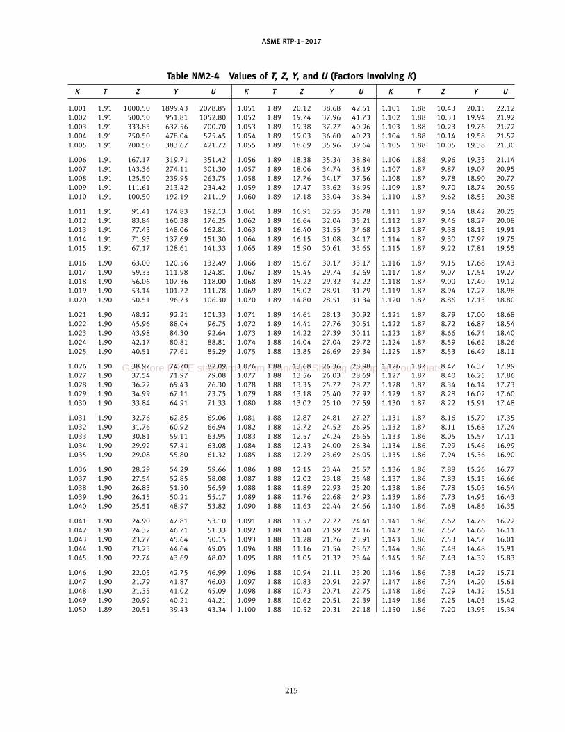
ASME RTP-1–2017
Table NM2-4 Values of T, Z, Y, and U (Factors Involving K)
K T Z Y U K T Z Y U K T Z Y U
1.001 1.91 1000.50 1899.43 2078.85 1.051 1.89 20.12 38.68 42.51 1.101 1.88 10.43 20.15 22.121.002 1.91 500.50 951.81 1052.80 1.052 1.89 19.74 37.96 41.73 1.102 1.88 10.33 19.94 21.921.003 1.91 333.83 637.56 700.70 1.053 1.89 19.38 37.27 40.96 1.103 1.88 10.23 19.76 21.721.004 1.91 250.50 478.04 525.45 1.054 1.89 19.03 36.60 40.23 1.104 1.88 10.14 19.58 21.521.005 1.91 200.50 383.67 421.72 1.055 1.89 18.69 35.96 39.64 1.105 1.88 10.05 19.38 21.30
1.006 1.91 167.17 319.71 351.42 1.056 1.89 18.38 35.34 38.84 1.106 1.88 9.96 19.33 21.141.007 1.91 143.36 274.11 301.30 1.057 1.89 18.06 34.74 38.19 1.107 1.87 9.87 19.07 20.951.008 1.91 125.50 239.95 263.75 1.058 1.89 17.76 34.17 37.56 1.108 1.87 9.78 18.90 20.771.009 1.91 111.61 213.42 234.42 1.059 1.89 17.47 33.62 36.95 1.109 1.87 9.70 18.74 20.591.010 1.91 100.50 192.19 211.19 1.060 1.89 17.18 33.04 36.34 1.110 1.87 9.62 18.55 20.38
1.011 1.91 91.41 174.83 192.13 1.061 1.89 16.91 32.55 35.78 1.111 1.87 9.54 18.42 20.251.012 1.91 83.84 160.38 176.25 1.062 1.89 16.64 32.04 35.21 1.112 1.87 9.46 18.27 20.081.013 1.91 77.43 148.06 162.81 1.063 1.89 16.40 31.55 34.68 1.113 1.87 9.38 18.13 19.911.014 1.91 71.93 137.69 151.30 1.064 1.89 16.15 31.08 34.17 1.114 1.87 9.30 17.97 19.751.015 1.91 67.17 128.61 141.33 1.065 1.89 15.90 30.61 33.65 1.115 1.87 9.22 17.81 19.55
1.016 1.90 63.00 120.56 132.49 1.066 1.89 15.67 30.17 33.17 1.116 1.87 9.15 17.68 19.431.017 1.90 59.33 111.98 124.81 1.067 1.89 15.45 29.74 32.69 1.117 1.87 9.07 17.54 19.271.018 1.90 56.06 107.36 118.00 1.068 1.89 15.22 29.32 32.22 1.118 1.87 9.00 17.40 19.121.019 1.90 53.14 101.72 111.78 1.069 1.89 15.02 28.91 31.79 1.119 1.87 8.94 17.27 18.981.020 1.90 50.51 96.73 106.30 1.070 1.89 14.80 28.51 31.34 1.120 1.87 8.86 17.13 18.80
1.021 1.90 48.12 92.21 101.33 1.071 1.89 14.61 28.13 30.92 1.121 1.87 8.79 17.00 18.681.022 1.90 45.96 88.04 96.75 1.072 1.89 14.41 27.76 30.51 1.122 1.87 8.72 16.87 18.541.023 1.90 43.98 84.30 92.64 1.073 1.89 14.22 27.39 30.11 1.123 1.87 8.66 16.74 18.401.024 1.90 42.17 80.81 88.81 1.074 1.88 14.04 27.04 29.72 1.124 1.87 8.59 16.62 18.261.025 1.90 40.51 77.61 85.29 1.075 1.88 13.85 26.69 29.34 1.125 1.87 8.53 16.49 18.11
1.026 1.90 38.97 74.70 82.09 1.076 1.88 13.68 26.36 28.98 1.126 1.87 8.47 16.37 17.991.027 1.90 37.54 71.97 79.08 1.077 1.88 13.56 26.03 28.69 1.127 1.87 8.40 16.25 17.861.028 1.90 36.22 69.43 76.30 1.078 1.88 13.35 25.72 28.27 1.128 1.87 8.34 16.14 17.731.029 1.90 34.99 67.11 73.75 1.079 1.88 13.18 25.40 27.92 1.129 1.87 8.28 16.02 17.601.030 1.90 33.84 64.91 71.33 1.080 1.88 13.02 25.10 27.59 1.130 1.87 8.22 15.91 17.48
1.031 1.90 32.76 62.85 69.06 1.081 1.88 12.87 24.81 27.27 1.131 1.87 8.16 15.79 17.351.032 1.90 31.76 60.92 66.94 1.082 1.88 12.72 24.52 26.95 1.132 1.87 8.11 15.68 17.241.033 1.90 30.81 59.11 63.95 1.083 1.88 12.57 24.24 26.65 1.133 1.86 8.05 15.57 17.111.034 1.90 29.92 57.41 63.08 1.084 1.88 12.43 24.00 26.34 1.134 1.86 7.99 15.46 16.991.035 1.90 29.08 55.80 61.32 1.085 1.88 12.29 23.69 26.05 1.135 1.86 7.94 15.36 16.90
1.036 1.90 28.29 54.29 59.66 1.086 1.88 12.15 23.44 25.57 1.136 1.86 7.88 15.26 16.771.037 1.90 27.54 52.85 58.08 1.087 1.88 12.02 23.18 25.48 1.137 1.86 7.83 15.15 16.661.038 1.90 26.83 51.50 56.59 1.088 1.88 11.89 22.93 25.20 1.138 1.86 7.78 15.05 16.541.039 1.90 26.15 50.21 55.17 1.089 1.88 11.76 22.68 24.93 1.139 1.86 7.73 14.95 16.431.040 1.90 25.51 48.97 53.82 1.090 1.88 11.63 22.44 24.66 1.140 1.86 7.68 14.86 16.35
1.041 1.90 24.90 47.81 53.10 1.091 1.88 11.52 22.22 24.41 1.141 1.86 7.62 14.76 16.221.042 1.90 24.32 46.71 51.33 1.092 1.88 11.40 21.99 24.16 1.142 1.86 7.57 14.66 16.111.043 1.90 23.77 45.64 50.15 1.093 1.88 11.28 21.76 23.91 1.143 1.86 7.53 14.57 16.011.044 1.90 23.23 44.64 49.05 1.094 1.88 11.16 21.54 23.67 1.144 1.86 7.48 14.48 15.911.045 1.90 22.74 43.69 48.02 1.095 1.88 11.05 21.32 23.44 1.145 1.86 7.43 14.39 15.83
1.046 1.90 22.05 42.75 46.99 1.096 1.88 10.94 21.11 23.20 1.146 1.86 7.38 14.29 15.711.047 1.90 21.79 41.87 46.03 1.097 1.88 10.83 20.91 22.97 1.147 1.86 7.34 14.20 15.611.048 1.90 21.35 41.02 45.09 1.098 1.88 10.73 20.71 22.75 1.148 1.86 7.29 14.12 15.511.049 1.90 20.92 40.21 44.21 1.099 1.88 10.62 20.51 22.39 1.149 1.86 7.25 14.03 15.421.050 1.89 20.51 39.43 43.34 1.100 1.88 10.52 20.31 22.18 1.150 1.86 7.20 13.95 15.34
215
Get more FREE standards from Standard Sharing Group and our chats

ASME RTP-1–2017
Table NM2-4 Values of T, Z, Y, and U (Factors Involving K) (Cont’d)
K T Z Y U K T Z Y U K T Z Y U
1.151 1.86 7.16 13.86 15.23 1.201 1.84 5.52 10.70 11.76 1.251 1.82 4.54 8.80 9.671.152 1.86 7.11 13.77 15.14 1.202 1.84 5.50 10.65 11.71 1.252 1.82 4.52 8.77 9.641.153 1.86 7.07 13.69 15.05 1.203 1.84 5.47 10.61 11.66 1.253 1.82 4.51 8.74 9.601.154 1.86 7.03 13.61 14.96 1.204 1.84 5.45 10.56 11.61 1.254 1.82 4.49 8.71 9.571.155 1.86 6.99 13.54 14.87 1.205 1.84 5.42 10.52 11.56 1.255 1.82 4.48 8.68 9.54
1.156 1.86 6.95 13.45 14.78 1.206 1.84 5.40 10.47 11.51 1.256 1.82 4.46 8.65 9.511.157 1.86 6.91 13.37 14.70 1.207 1.84 5.38 10.43 11.46 1.257 1.82 4.45 8.62 9.471.158 1.86 6.87 13.30 14.61 1.208 1.84 5.35 10.38 11.41 1.258 1.81 4.43 8.59 9.441.159 1.86 6.83 13.22 14.53 1.209 1.84 5.33 10.34 11.36 1.259 1.81 4.42 8.56 9.411.160 1.86 6.79 13.15 14.45 1.210 1.84 5.31 10.30 11.32 1.260 1.81 4.40 8.53 9.38
1.161 1.85 6.75 13.07 14.36 1.211 1.83 5.29 10.25 11.27 1.261 1.81 4.39 8.51 9.351.162 1.85 6.71 13.00 14.28 1.212 1.83 5.27 10.21 11.22 1.262 1.81 4.37 8.49 9.321.163 1.85 6.67 12.92 14.20 1.213 1.83 5.24 10.16 11.17 1.263 1.81 4.36 8.45 9.281.164 1.85 6.64 12.85 14.12 1.214 1.83 5.22 10.12 11.12 1.264 1.81 4.35 8.42 9.251.165 1.85 6.60 12.78 14.04 1.215 1.83 5.20 10.09 11.09 1.265 1.81 4.33 8.39 9.23
1.166 1.85 6.56 12.71 13.97 1.216 1.83 5.18 10.04 11.03 1.266 1.81 4.32 8.37 9.191.167 1.85 6.53 12.64 13.89 1.217 1.83 5.16 10.00 10.99 1.267 1.81 4.30 8.34 9.161.168 1.85 6.49 12.58 13.82 1.218 1.83 5.14 9.96 10.94 1.268 1.81 4.29 8.31 9.141.169 1.85 6.46 12.51 13.74 1.219 1.83 5.12 9.92 10.90 1.269 1.81 4.28 8.29 9.111.170 1.85 6.42 12.43 13.66 1.220 1.83 5.10 9.89 10.87 1.270 1.81 4.26 8.26 9.08
1.171 1.85 6.39 12.38 13.60 1.221 1.83 5.07 9.84 10.81 1.271 1.81 4.25 8.23 9.051.172 1.85 6.35 12.31 13.53 1.222 1.83 5.05 9.80 10.77 1.272 1.81 4.24 8.21 9.021.173 1.85 6.32 12.25 13.46 1.223 1.83 5.03 9.76 10.73 1.273 1.81 4.22 8.18 8.991.174 1.85 6.29 12.18 13.39 1.224 1.83 5.01 9.72 10.68 1.274 1.81 4.21 8.15 8.961.175 1.85 6.25 12.10 13.30 1.225 1.83 5.00 9.69 10.65 1.275 1.81 4.20 8.13 8.93
1.176 1.85 6.22 12.06 13.25 1.226 1.83 4.98 9.65 10.60 1.276 1.81 4.18 8.11 8.911.177 1.85 6.19 12.00 13.18 1.227 1.83 4.96 9.61 10.56 1.277 1.81 4.17 8.08 8.881.178 1.85 6.16 11.93 13.11 1.228 1.83 4.94 9.57 10.52 1.278 1.81 4.16 8.05 8.851.179 1.85 6.13 11.87 13.05 1.229 1.83 4.92 9.53 10.48 1.279 1.81 4.15 8.03 8.821.180 1.85 6.10 11.79 12.96 1.230 1.83 4.90 9.50 10.44 1.280 1.81 4.13 8.01 8.79
1.181 1.85 6.07 11.76 12.92 1.231 1.83 4.88 9.46 10.40 1.281 1.81 4.12 7.98 8.771.182 1.85 6.04 11.70 12.86 1.232 1.83 4.86 9.43 10.36 1.282 1.81 4.11 7.96 8.741.183 1.85 6.01 11.64 12.79 1.233 1.83 4.84 9.39 10.32 1.283 1.80 4.10 7.93 8.711.184 1.85 5.98 11.58 12.73 1.234 1.83 4.83 9.36 10.28 1.284 1.80 4.08 7.91 8.691.185 1.85 5.95 11.50 12.64 1.235 1.83 4.81 9.32 10.24 1.285 1.80 4.07 7.89 8.66
1.186 1.85 5.92 11.47 12.61 1.236 1.82 4.79 9.29 10.20 1.286 1.80 4.06 7.86 8.641.187 1.85 5.89 11.42 12.54 1.237 1.82 4.77 9.25 10.17 1.287 1.80 4.05 7.84 8.611.188 1.85 5.86 11.36 12.49 1.238 1.82 4.76 9.22 10.13 1.288 1.80 4.04 7.81 8.591.189 1.85 5.83 11.31 12.43 1.239 1.82 4.74 9.18 10.09 1.289 1.80 4.02 7.79 8.561.190 1.84 5.81 11.26 12.37 1.240 1.82 4.72 9.15 10.05 1.290 1.80 4.01 7.77 8.53
1.191 1.84 5.78 11.20 12.31 1.241 1.82 4.70 9.12 10.02 1.291 1.80 4.00 7.75 8.511.192 1.84 5.75 11.15 12.25 1.242 1.82 4.69 9.08 9.98 1.292 1.80 3.99 7.72 8.481.193 1.84 5.73 11.10 12.20 1.243 1.82 4.67 9.05 9.95 1.293 1.80 3.98 7.70 8.461.194 1.84 5.70 11.05 12.14 1.244 1.82 4.65 9.02 9.91 1.294 1.80 3.97 7.68 8.431.195 1.84 5.67 11.00 12.08 1.245 1.82 4.64 8.99 9.87 1.295 1.80 3.95 7.66 8.41
1.196 1.84 5.65 10.95 12.03 1.246 1.82 4.62 8.95 9.84 1.296 1.80 3.94 7.63 8.391.197 1.84 5.62 10.90 11.97 1.247 1.82 4.60 8.92 9.81 1.297 1.80 3.93 7.61 8.361.198 1.84 5.60 10.85 11.92 1.248 1.82 4.59 8.89 9.77 1.298 1.80 3.92 7.59 8.331.199 1.84 5.57 10.80 11.87 1.249 1.82 4.57 8.86 9.74 1.299 1.80 3.91 7.57 8.311.200 1.84 5.55 10.75 11.81 1.250 1.82 4.56 8.83 9.70 1.300 1.80 3.90 7.55 8.29
216
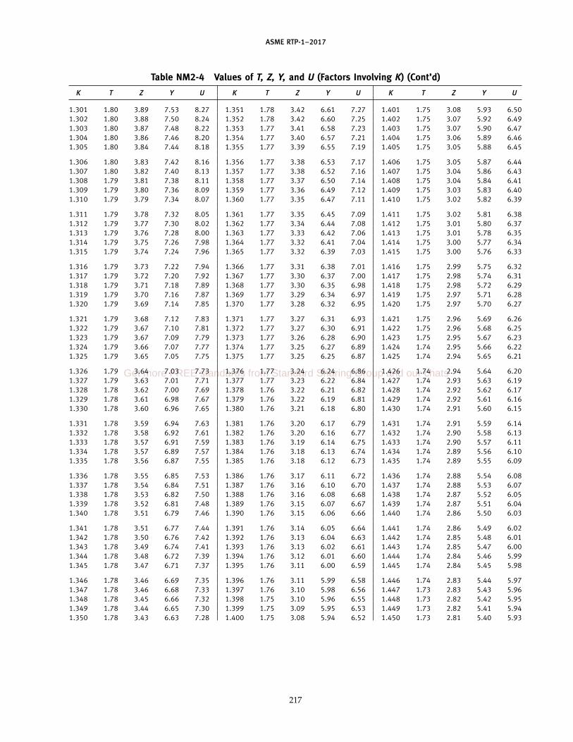
ASME RTP-1–2017
Table NM2-4 Values of T, Z, Y, and U (Factors Involving K) (Cont’d)
K T Z Y U K T Z Y U K T Z Y U
1.301 1.80 3.89 7.53 8.27 1.351 1.78 3.42 6.61 7.27 1.401 1.75 3.08 5.93 6.501.302 1.80 3.88 7.50 8.24 1.352 1.78 3.42 6.60 7.25 1.402 1.75 3.07 5.92 6.491.303 1.80 3.87 7.48 8.22 1.353 1.77 3.41 6.58 7.23 1.403 1.75 3.07 5.90 6.471.304 1.80 3.86 7.46 8.20 1.354 1.77 3.40 6.57 7.21 1.404 1.75 3.06 5.89 6.461.305 1.80 3.84 7.44 8.18 1.355 1.77 3.39 6.55 7.19 1.405 1.75 3.05 5.88 6.45
1.306 1.80 3.83 7.42 8.16 1.356 1.77 3.38 6.53 7.17 1.406 1.75 3.05 5.87 6.441.307 1.80 3.82 7.40 8.13 1.357 1.77 3.38 6.52 7.16 1.407 1.75 3.04 5.86 6.431.308 1.79 3.81 7.38 8.11 1.358 1.77 3.37 6.50 7.14 1.408 1.75 3.04 5.84 6.411.309 1.79 3.80 7.36 8.09 1.359 1.77 3.36 6.49 7.12 1.409 1.75 3.03 5.83 6.401.310 1.79 3.79 7.34 8.07 1.360 1.77 3.35 6.47 7.11 1.410 1.75 3.02 5.82 6.39
1.311 1.79 3.78 7.32 8.05 1.361 1.77 3.35 6.45 7.09 1.411 1.75 3.02 5.81 6.381.312 1.79 3.77 7.30 8.02 1.362 1.77 3.34 6.44 7.08 1.412 1.75 3.01 5.80 6.371.313 1.79 3.76 7.28 8.00 1.363 1.77 3.33 6.42 7.06 1.413 1.75 3.01 5.78 6.351.314 1.79 3.75 7.26 7.98 1.364 1.77 3.32 6.41 7.04 1.414 1.75 3.00 5.77 6.341.315 1.79 3.74 7.24 7.96 1.365 1.77 3.32 6.39 7.03 1.415 1.75 3.00 5.76 6.33
1.316 1.79 3.73 7.22 7.94 1.366 1.77 3.31 6.38 7.01 1.416 1.75 2.99 5.75 6.321.317 1.79 3.72 7.20 7.92 1.367 1.77 3.30 6.37 7.00 1.417 1.75 2.98 5.74 6.311.318 1.79 3.71 7.18 7.89 1.368 1.77 3.30 6.35 6.98 1.418 1.75 2.98 5.72 6.291.319 1.79 3.70 7.16 7.87 1.369 1.77 3.29 6.34 6.97 1.419 1.75 2.97 5.71 6.281.320 1.79 3.69 7.14 7.85 1.370 1.77 3.28 6.32 6.95 1.420 1.75 2.97 5.70 6.27
1.321 1.79 3.68 7.12 7.83 1.371 1.77 3.27 6.31 6.93 1.421 1.75 2.96 5.69 6.261.322 1.79 3.67 7.10 7.81 1.372 1.77 3.27 6.30 6.91 1.422 1.75 2.96 5.68 6.251.323 1.79 3.67 7.09 7.79 1.373 1.77 3.26 6.28 6.90 1.423 1.75 2.95 5.67 6.231.324 1.79 3.66 7.07 7.77 1.374 1.77 3.25 6.27 6.89 1.424 1.74 2.95 5.66 6.221.325 1.79 3.65 7.05 7.75 1.375 1.77 3.25 6.25 6.87 1.425 1.74 2.94 5.65 6.21
1.326 1.79 3.64 7.03 7.73 1.376 1.77 3.24 6.24 6.86 1.426 1.74 2.94 5.64 6.201.327 1.79 3.63 7.01 7.71 1.377 1.77 3.23 6.22 6.84 1.427 1.74 2.93 5.63 6.191.328 1.78 3.62 7.00 7.69 1.378 1.76 3.22 6.21 6.82 1.428 1.74 2.92 5.62 6.171.329 1.78 3.61 6.98 7.67 1.379 1.76 3.22 6.19 6.81 1.429 1.74 2.92 5.61 6.161.330 1.78 3.60 6.96 7.65 1.380 1.76 3.21 6.18 6.80 1.430 1.74 2.91 5.60 6.15
1.331 1.78 3.59 6.94 7.63 1.381 1.76 3.20 6.17 6.79 1.431 1.74 2.91 5.59 6.141.332 1.78 3.58 6.92 7.61 1.382 1.76 3.20 6.16 6.77 1.432 1.74 2.90 5.58 6.131.333 1.78 3.57 6.91 7.59 1.383 1.76 3.19 6.14 6.75 1.433 1.74 2.90 5.57 6.111.334 1.78 3.57 6.89 7.57 1.384 1.76 3.18 6.13 6.74 1.434 1.74 2.89 5.56 6.101.335 1.78 3.56 6.87 7.55 1.385 1.76 3.18 6.12 6.73 1.435 1.74 2.89 5.55 6.09
1.336 1.78 3.55 6.85 7.53 1.386 1.76 3.17 6.11 6.72 1.436 1.74 2.88 5.54 6.081.337 1.78 3.54 6.84 7.51 1.387 1.76 3.16 6.10 6.70 1.437 1.74 2.88 5.53 6.071.338 1.78 3.53 6.82 7.50 1.388 1.76 3.16 6.08 6.68 1.438 1.74 2.87 5.52 6.051.339 1.78 3.52 6.81 7.48 1.389 1.76 3.15 6.07 6.67 1.439 1.74 2.87 5.51 6.041.340 1.78 3.51 6.79 7.46 1.390 1.76 3.15 6.06 6.66 1.440 1.74 2.86 5.50 6.03
1.341 1.78 3.51 6.77 7.44 1.391 1.76 3.14 6.05 6.64 1.441 1.74 2.86 5.49 6.021.342 1.78 3.50 6.76 7.42 1.392 1.76 3.13 6.04 6.63 1.442 1.74 2.85 5.48 6.011.343 1.78 3.49 6.74 7.41 1.393 1.76 3.13 6.02 6.61 1.443 1.74 2.85 5.47 6.001.344 1.78 3.48 6.72 7.39 1.394 1.76 3.12 6.01 6.60 1.444 1.74 2.84 5.46 5.991.345 1.78 3.47 6.71 7.37 1.395 1.76 3.11 6.00 6.59 1.445 1.74 2.84 5.45 5.98
1.346 1.78 3.46 6.69 7.35 1.396 1.76 3.11 5.99 6.58 1.446 1.74 2.83 5.44 5.971.347 1.78 3.46 6.68 7.33 1.397 1.76 3.10 5.98 6.56 1.447 1.73 2.83 5.43 5.961.348 1.78 3.45 6.66 7.32 1.398 1.75 3.10 5.96 6.55 1.448 1.73 2.82 5.42 5.951.349 1.78 3.44 6.65 7.30 1.399 1.75 3.09 5.95 6.53 1.449 1.73 2.82 5.41 5.941.350 1.78 3.43 6.63 7.28 1.400 1.75 3.08 5.94 6.52 1.450 1.73 2.81 5.40 5.93
217
Get more FREE standards from Standard Sharing Group and our chats

ASME RTP-1–2017
Table NM2-4 Values of T, Z, Y, and U (Factors Involving K) (Cont’d)
K T Z Y U K T Z Y U K T Z Y U
1.451 1.73 2.81 5.39 5.92 1.496 1.71 2.62 4.99 5.48 1.541 1.69 2.45 4.66 5.121.452 1.73 2.80 5.38 5.91 1.497 1.71 2.61 4.98 5.47 1.542 1.69 2.45 4.65 5.111.453 1.73 2.80 5.37 5.90 1.498 1.71 2.61 4.98 5.47 1.543 1.69 2.45 4.64 5.111.454 1.73 2.80 5.36 5.89 1.499 1.71 2.60 4.97 5.46 1.544 1.69 2.45 4.64 5.101.455 1.73 2.79 5.35 5.88 1.500 1.71 2.60 4.96 5.45 1.545 1.69 2.44 4.63 5.09
1.456 1.73 2.79 5.34 5.87 1.501 1.71 2.60 4.95 5.44 1.546 1.69 2.44 4.63 5.081.457 1.73 2.78 5.33 5.86 1.502 1.71 2.59 4.94 5.43 1.547 1.69 2.44 4.62 5.071.458 1.73 2.78 5.32 5.85 1.503 1.71 2.59 4.94 5.43 1.548 1.69 2.43 4.62 5.071.459 1.73 2.77 5.31 5.84 1.504 1.71 2.58 4.93 5.42 1.549 1.69 2.43 4.61 5.061.460 1.73 2.77 5.30 5.83 1.505 1.71 2.58 4.92 5.41 1.550 1.69 2.43 4.60 5.05
1.461 1.73 2.76 5.29 5.82 1.506 1.71 2.58 4.91 5.40 1.551 1.69 2.42 4.60 5.051.462 1.73 2.76 5.28 5.80 1.507 1.71 2.57 4.90 5.39 1.552 1.69 2.42 4.59 5.041.463 1.73 2.75 5.27 5.79 1.508 1.71 2.57 4.90 5.39 1.553 1.69 2.42 4.58 5.031.464 1.73 2.75 5.26 5.78 1.509 1.71 2.57 4.89 5.38 1.554 1.69 2.41 4.58 5.031.465 1.73 2.74 5.25 5.77 1.510 1.71 2.56 4.88 5.37 1.555 1.69 2.41 4.57 5.02
1.466 1.73 2.74 5.24 5.76 1.511 1.71 2.56 4.87 5.36 1.556 1.69 2.41 4.57 5.021.467 1.73 2.74 5.23 5.74 1.512 1.71 2.56 4.86 5.35 1.557 1.69 2.40 4.56 5.011.468 1.72 2.73 5.22 5.73 1.513 1.71 2.55 4.86 5.35 1.558 1.69 2.40 4.56 5.001.469 1.72 2.73 5.21 5.72 1.514 1.71 2.55 4.85 5.34 1.559 1.69 2.40 4.55 4.991.470 1.72 2.72 5.20 5.71 1.515 1.71 2.54 4.84 5.33 1.560 1.69 2.40 4.54 4.99
1.471 1.72 2.72 5.19 5.70 1.516 1.71 2.54 4.83 5.32 1.561 1.69 2.39 4.54 4.981.472 1.72 2.71 5.18 5.69 1.517 1.71 2.54 4.82 5.31 1.562 1.69 2.39 4.53 4.971.473 1.72 2.71 5.18 5.68 1.518 1.71 2.53 4.82 5.31 1.563 1.68 2.39 4.52 4.971.474 1.72 2.71 5.17 5.67 1.519 1.70 2.53 4.81 5.30 1.564 1.68 2.38 4.51 4.961.475 1.72 2.70 5.16 5.66 1.520 1.70 2.53 4.80 5.29 1.565 1.68 2.38 4.51 4.95
1.476 1.72 2.70 5.15 5.65 1.521 1.70 2.52 4.79 5.28 1.566 1.68 2.38 4.50 4.951.477 1.72 2.69 5.14 5.64 1.522 1.70 2.52 4.79 5.27 1.567 1.68 2.37 4.50 4.941.478 1.72 2.69 5.14 5.63 1.523 1.70 2.52 4.78 5.27 1.568 1.68 2.37 4.49 4.931.479 1.72 2.68 5.13 5.62 1.524 1.70 2.51 4.78 5.26 1.569 1.68 2.37 4.48 4.921.480 1.72 2.68 5.12 5.61 1.525 1.70 2.51 4.77 5.25 1.570 1.68 2.37 4.48 4.92
1.481 1.72 2.68 5.11 5.60 1.526 1.70 2.51 4.77 5.24 1.571 1.68 2.36 4.47 4.911.482 1.72 2.67 5.10 5.59 1.527 1.70 2.50 4.76 5.23 1.572 1.68 2.36 4.47 4.911.483 1.72 2.67 5.10 5.59 1.528 1.70 2.50 4.76 5.23 1.573 1.68 2.36 4.46 4.901.484 1.72 2.66 5.09 5.58 1.529 1.70 2.49 4.75 5.22 1.574 1.68 2.35 4.46 4.891.485 1.72 2.66 5.08 5.57 1.530 1.70 2.49 4.74 5.21 1.575 1.68 2.35 4.45 4.89
1.486 1.72 2.66 5.07 5.56 1.531 1.70 2.49 4.73 5.20 1.576 1.68 2.35 4.44 4.881.487 1.72 2.65 5.06 5.55 1.532 1.70 2.48 4.72 5.19 1.577 1.68 2.35 4.44 4.881.488 1.72 2.65 5.06 5.55 1.533 1.70 2.48 4.72 5.19 1.578 1.68 2.34 4.43 4.871.489 1.72 2.64 5.05 5.54 1.534 1.70 2.48 4.71 5.18 1.579 1.68 2.34 4.42 4.861.490 1.72 2.64 5.04 5.53 1.535 1.70 2.47 4.70 5.17 1.580 1.68 2.34 4.42 4.86
1.491 1.72 2.64 5.03 5.52 1.536 1.70 2.47 4.69 5.16 . . . . . . . . . . . . . . .1.492 1.72 2.63 5.02 5.51 1.537 1.70 2.47 4.68 5.15 . . . . . . . . . . . . . . .1.493 1.71 2.63 5.02 5.51 1.538 1.69 2.46 4.68 5.15 . . . . . . . . . . . . . . .1.494 1.71 2.62 5.01 5.50 1.539 1.69 2.46 4.67 5.14 . . . . . . . . . . . . . . .1.495 1.71 2.62 5.00 5.49 1.540 1.69 2.46 4.66 5.13 . . . . . . . . . . . . . . .
218

ASME RTP-1–2017
NONMANDATORY APPENDIX NM-3SEISMIC, WIND, AND SNOW LOADINGS
NM3-100 TYPICAL CODES
The User/Purchaser shall be responsible for the speci-fication of the appropriate code to be used. The codespecifies to the designer the magnitude and directionof the seismic, wind, and snow loads acting on the vessel.The designer shall use recognized stress analysis meth-ods to compute the stresses resulting from these loads.
The following is a list of examples of internationalcodes, standards, and manuals that may serve to deter-mine seismic, wind, and snow loads acting on the vessel:
(a) Uniform Building Code, published byInternational Code Council
(b) National Building Code, published by AmericanInsurance Association
(c) Minimum Design Loads for Buildings and OtherStructures, ASCE 7, published by American Society ofCivil Engineers
(d) International Building Code, published byInternational Code Council
(e) Standard Building Code, published byInternational Code Council
(f ) British Standard BS 6399 Part 2, Loading forBuildings, Code of Practice for Wind Loads
(g) Dutch Standard NEN 6702 — TGB 1990, Loadingsand Deformations
(h) Eurocode 1, Part 2-4, Basis of Design and Actionson Structures
(i) Eurocode 8, Part 1-5, Design Provisions forEarthquake Resistance of Structures
(j) Mexican Code, Manual de Diseno de Obras Civilesde la Comision Federal de Electricidad
(k) National Building Code of Canada
NOTE: The Professional Engineer who certifies the Fabricator’sDesign Report per requirements of Part 1, para. 1-300 of thisStandard should verify that the Code given in UBRS is used. IfCode (e.g., IBC) is not specified in UBRS, Professional Engineer,or Fabricator, should make a request that User/Purchaser specifiesCode in writing.
NM3-200 NOMENCLATURE
C p distance of neutral axis, in.D p nominal vessel diameter, ftDi p inside diameter, in.Do p outside diameter, in.E p tensile modulus of elasticity, psiF p design factor
Fcra p allowable axial stress (buckling)
219
Fcrb p allowable flexural stress (buckling)Fcrv p allowable shear stress (buckling)
Fh p allowable hoop tensile stress (ultimate)fa p axial stressfb p flexural stress
fcra p critical axial buckling stressfcrb p critical flexural buckling stressfcrv p critical shear buckling stress
fh p hoop tensile stressfv p shear stressH p vessel height, ftI p moment of inertia of vessel shell cross
section, in.4
Mw p bending moment due to wind load, ft-lbNa p axial stress resultant, lb/in.P p hydrostatic pressure (total), psigq p wind pressure, psf
Rc p head crown radius, in.Su p ultimate tensile strength, psiSF p shape factorU p uniform wind pressure load, lb/ft
UT p wind load on top flange, lb/ftW p total wind load, lb
NM3-300 EXAMPLES
(a) Wind Loads(1) cantilevered vessel empty (flat bottomed on
slab)(2) suspended vessel empty (ring or skirt
supported)(3) cantilevered vessel at design conditions(4) suspended vessel at design conditions
(b) Snow Load on Empty Vessel. The snow load exam-ple below assumes that the detailed design of the tophead has been done such that the snow load is trans-ferred uniformly to the shell. The snow load on the tophead is assumed to be a uniform external pressure onthe cover. See para. 3A-320. All the example vessels arebuilt of Type I or Type II laminates.
(c) Seismic Load on Flat-Bottom Vertical Tank
NM3-310 Loading Criteria
In the examples below, the load causes shear stressand normal stress in both axial and hoop directions,all simultaneously. In some cases, the normal stress iscompressive, which, if excessive, could cause buckling.
Get more FREE standards from Standard Sharing Group and our chats
ASME RTP-1–2017
Therefore, biaxial strength and buckling criteria areneeded to complete the examples.
(a) Paragraphs 3B-500 and M3-530 contain provisions,based on lamination analysis, for calculating the resist-ance of any type of laminate to biaxial stress; however,the calculations are complicated. For Type I laminates,a conservative approximation to these provisions is
f2a − fafh + f2
h + 2.25f2v < (Su/F)2
For Type II laminates, a conservative approximation toparas. 3B-300 and M3-530 is
fa p Su/F and fh p Su/F
if the shear stress is less than 200 psi. These approxima-tions are used in this Appendix instead of the more exactprocedure in paras. 3B-300 and M3-530. According topara. 3B-500, the design factor F p 10 for sustainedloads, and F p 10/1.2 p 8.33 for wind, seismic, or snowloads, or for a combination of sustained loads and wind,seismic, or snow loads.
(b) The interaction criterion for buckling is
faF/fcra + fbF/fcrb + (fvF/fcrv)2 < 1
This equation applies only to compressive normal stress.In all cases, the design factor F p 5 for buckling. Thebuckling criterion is the same as in Equation 9.93, page1006, of the American Society of Civil Engineers’Structural Plastics Design Manual, ASCE Manuals andReports on Engineering Practice No. 63, 1984.
NM3-320 Design for Sustained Loads
Case (a) is a vented tank with a flat-bottom headand a torispherical top head. The tank is constructed ofType II laminate, bolted to a concrete pad, 12 ft in diame-ter and 24 ft high, and contains a liquid with a specificgravity of 1.2. The tank is located outdoors in St. Louis,Missouri.
Paragraph 3A-210 requires a shell thickness given by:
t p FPDi/2Su
p (10)(24)(12)(0.03613)(1.2)(144)/(2)(15,000)p 0.599 in.
The laminate strength is from Table 2A-3, for Type IIlaminate. The next thickest standard Type II laminate is0.64 in. thick (Table 2A-2). Thus, take t p 0.64 in. Assumethat the shell tapers to 0.22 in. thick at the top, that thehead is 0.29 in. thick, and that the flat bottom head is0.37 in. thick. Then the shell weighs 3,500 lb, the tophead weighs 319 lb, and the bottom weighs 340 lb, fora total vessel weight of 4,159 lb.
Case (b) is a vented tank 9 ft in diameter and 18 ftlong from tangent line to tangent line. It has torisphericalheads on both ends and it is supported by a ring 6 ftfrom the top of the shell. As in case (a), it is located
220
outdoors in St. Louis, Missouri and contains a liquidwith specific gravity p 1.2. The vessel is constructed ofType I laminate, which has Su p 9,000 psi according toTable 2A-3. Paragraph 3A-230 requires that the bottomhead have the following thickness:
t p 0.885 FPRc/Su
p (10)(0.885)(18)(12)(0.03613)(1.2)(108)/9,000p 0.995 in.
(Use 1.00 in. nominal thickness, per Table 2A-2.) Thetop head thickness would be governed by the “footprint”load specified by para. 3A-340. NonmandatoryAppendix NM-11 gives a method for designing for thisload, which in this case gives a thickness of 0.35 in. Theshell thickness just above the ring is given bypara. 3A-210 as follows:
t p FPDi/2Su
p (10)(6)(12)(0.03613)(1.2)(108)/(2)(9,000)p 0.187 in.
However, para. 3-200(f) and Table 2A-1, taken together,require that the thickness of the shell be at least 0.23 in.Similarly, the shell thickness 12 ft from the top isfound from
t p FPDi/2Su
p (10)(12)(12)(0.03613)(1.2)(108)/(2)(9,000)p 0.375 in.
or, rounding up to a standard laminate, t p 0.40 in. Theshell thickness 18 ft from the top is found the same way
t p FPDi/2Su
p (10)(18)(12)(0.03613)(1.2)(108)/(2)(9,000)p 0.562 in.
which rounds up to 0.57 in. The total weight of the liquidis found from
weight p (3.1416)(4.5)2(18)(62.4)(1.2) p 85,746 lb
The vessel weighs approximately 2,000 lb; therefore, theaxial stress resultant just below the ring is
Na p (85,746 + 2,000)/(3.1416)(108) p 259 lb/in.
The thickness required to resist the axial load is givenby para. 3A-210
t p FNa/Su
p (10)(259)/(9,000) p 0.287 in.
which is less than the thickness required to resist thehoop stress. Thus, hoop stress governs and t p 0.57 in.
NM3-321 Example (a2): Empty Cantilevered VesselUnder Wind Load. This is a continuation of case (a) in

ASME RTP-1–2017
para. NM3-320; it is the same flat-bottom tank with windloading. According to Uniform Building Code (UBC)rules, the wind pressure zone for St. Louis is 30. FromUBC Table 23-F, the design wind pressure for zone 30is 25 psf. The shape factor per Table 23-G is SF p 0.8.Then the wind load is
U p (SF)qD p (0.8)(25)(12) p 240 lb/ft of height
The bending moment at the base of the vessel is
Mw p 1⁄2UH2
p (0.5)(240)(24)2
p 69,120 ft-lb p 829,440 in.-lb
and the total lateral force is
W p UH p (240)(24) p 5,760 lb
The total vessel weight is 4,159 lb and the weight ofthe bottom is 340 lb; thus, the weight transmittedthrough the shell at the base is 4,159 − 340 p 3,819 lb.The axial stress at the base is then
fa p −3,819/(3.1416)(144)(0.64) p −13.2 psi
where the negative sign denotes compression. The axialstress on the downwind side of the base resulting fromthe wind moment is given by
fb p −MwC/I
The moment of inertia is calculated from
I p (3.1416)(D4o − D4
i )/64
p (3.1416/64)(145.284 − 1444)
p 760,525 in.4
and C p 72.64 in. Thus
fb p −(829,440)(72.64)/(760,525) p −79.2 psi
The total axial stress is then fa + fb p −92.4 psi. The tankis built of Type II laminate, for which Su p 15,000 psi.However, F p 8.33 and the allowable stress is 15,000/8.33 p 1,800 psi. The shear stress is
fv p 5,760/(3.1416)(144)(0.64) p 19.9 psi
Since fv < 200 psi, the criterion for Type II laminatesstated in para. NM3-310 applies. It is
fa + fb p 92.4 < 1,800 psi
which satisfies para. NM3-310. Thus, the design isacceptable for wind load on the empty tank, as far asstrength is concerned.
221
The tank must also be checked for elastic stability.The critical buckling stress for uniformly distributedaxial compression is
fcra p 0.3Et/R
p (0.3)(1.5 � 106)(0.64)/72p 4,000 psi
The critical stress for buckling from bending under thewind moment is
fcrb p 1.3fcra p 5,200 psi
For shear, the critical buckling stress for thin-walled tubeof circular cross section is given by
fcrv p 0.695E(t/R)5⁄4(R/H)
1⁄2
p 0.695(1.5 � 106)(0.64/72)5⁄4(72/288)
1⁄2
p 1,423 psi
The buckling interaction equation from para. NM3-310 is
faF/fcra + fbF/fcrb + (fvF/fcrv)2 < 1
Inserting values for this example gives
(13.2)(5)/4,000 + (79.2)(5)/5,200
+ [(19.9)(5)/1,423]2 p 0.098 < 1
which shows that the empty tank will not fail by buck-ling under the design wind load. If the strength andbuckling conditions had not been satisfied, then the shellthickness would have to have been increased.
NM3-322 Empty Ring Supported Vessel Under WindLoad. This is a continuation of case (b) inpara. NM3-320. As before, the wind pressure is 25 psfand the shape factor is 0.8. The wind load U is
U p (SF)qDp (0.8)(25)(9) p 180 lb/ft
The total force above the ring is (180)(6) p 1,080 lb, andthe corresponding bending moment is 1⁄2 (1,080)(6) p3,240 ft-lb. The total force below the ring is (180)(12) p2,160 lb, and the corresponding moment is1⁄2(2,160)(12) p 12,960 ft-lb. This is the largest bendingmoment in the vessel. Thus, Mw p 12,960 ft-lb p155,520 in.-lb. Check the stress in the vessel just belowthe support ring.
(a) Axial. The weight of the shell below the supportplus the weight of the bottom head is 1,300 lb. The axialstress from the weight is then
fa p (1,300)/(3.1416)(108)(0.40)p 9.58 psi
(b) Bending Below the Support
fb p MwC/I
Get more FREE standards from Standard Sharing Group and our chats

ASME RTP-1–2017
I p (3.1416/64)(D4o − D4
i )
p (3.1416/64)(108.84 − 1084)
p 200,084 in.4
C p 54.4 in.
fb p (155,520)(54.4)/200,084p 42.3 psi
(c) Shear
fv p 2,160/(3.1416)(108)(0.40)p 15.9 psi
The strength criterion for Type I laminates is
f2a − fafh + f2
h + 2.25f2v < (Su/F)2
The axial stress is the sum of the stresses from weightand bending: fa p 9.58 + 42.3 p 51.9 psi. The hoopstress, fh, vanishes and fv p 15.9 psi. We insert thesevalues in the criterion
(51.9)2 + 2.25(15.9)2 p 3,262 < (9,000/8.33)2
p 1.17 � 106
which is satisfied. The axial stress from the weight istensile and, therefore, does not enter into the check forbuckling. The critical bending stress for buckling is
fcrb p (1.3)(0.3)Et/R
p (1.3)(0.3)(1.0 � 106)(0.4)/54p 2,889 psi
The critical shear buckling stress is
fcrv p 0.695E(t/R)5⁄4(R/H)
1⁄2
p (0.695)(1.0 � 106)(0.40/54)5⁄4(54/144)
1⁄2
p 925 psi
The buckling interaction formula is
faF/fcra + fbF/fcrb + (fvF/fcrv)2 < 1
With the current values in place
(5)(42.3)/2,889 + [(5)(15.9)/925]2 p 0.081 < 1
which is satisfied.Both strength and buckling criteria are fulfilled, and
the design is acceptable for withstanding wind loadswhile the vessel is empty.
NM3-323 Flat-Bottomed Vessel Under DesignConditions With Wind Load. The hoop stress due tohydrostatic pressure must be combined with the axial
222
stress caused by wind and weight, using a design factorof F p 10/1.2 p 8.33.
fh p PR/t
where P is the sum of hydrostatic and design pressures.
fh p (24)(12)(0.03613)(1.2)(72)/0.64 p 1,405 psi
From para. NM3-321, the bending stress is 79.2 psi, theaxial weight stress is 13.2 psi, and thus the overall axialstress is 79.2 + 13.2 p 92.4 psi. The shear stress is 19.9 psi,which is less than 200 psi, so the simplified criterion forType II laminates applies
fa p 92.4 < 15,000/8.33 p 1,800 psi
fh p 1,405 < 15,000/8.33 p 1,800 psi
which are both acceptable.
NM3-324 Ring Supported Vessel Under OperatingConditions and Wind Load. In this case, the hoop stressand axial stresses caused by the hydrostatic load mustbe superposed on the weight and wind stresses com-puted in para. NM3-322. The governing location is justunder the ring, and the hoop stress there is given by
fh p (6)(12)(0.03613)(1.2)(54)/0.40p 421 psi
Axial stresses are from the weight of the contents, theweight of the vessel, and the wind moment. The contentsweight is (3.1416)(4.5)2(18)(62.4)(1.2) p 85,746 lb. Theweight of the vessel below the support is 1,300 lb. Thenthe axial stress from weight is
fa p (85,746 + 1,300)/(3.1416)(108)(0.40)p 641 psi
The stress from the wind moment is 42.3 psi, and thetotal axial stress becomes 641 + 42.3 p 683.3 psi. Fromabove, the shear stress is 15.9 psi. The strength criterion is
f2a − fafh + f2
h + 2.25f2c < (Su/F)2
With the values from the example, this becomes
(683.3)2 − (683.3)(421) + (421)2 + 2.25(15.9)2 p 357,400
but 357,400 < (9,000/8.33)2 p 1.17 � 106, and the strengthis adequate.
NM3-325 Snow Load on Top Head of Flat-BottomedExample Vessel. The vessel top head must be designedto support the snow load and transfer the load to thevessel shell. The snow load can be treated as a uniformexternal pressure applied to the top head. The designsnow load in St. Louis is 25 psf. Thus, the weight of thesnow on the 12-ft diameter head p (3.1416)(6)2(25)p 2,827 lb. Taking the head weight as 275 lb, the

ASME RTP-1–2017
combined weight equals 3,102 lb. The weight causes anaxial stress in the shell
fa p 3,102/(3.1416)(144)(0.64) p 11 psi
The allowable stress for strength is 15,000/8.33 p 1,800psi, and the critical axial buckling stress was calculatedin para. NM3-321 as 4,000 psi. Thus, the allowable stressto ensure elastic stability is 4,000/5 p 800 psi. Bothallowable stresses are much greater than 11 psi, theapplied stress.
NOTE: If the vessel must withstand external pressure, the exter-nal pressure exerted by the snow must be added to the designexternal pressure for calculating the head thickness. Thus, if thevessel has a torispherical head, the head thickness is calculated bythe equation in para. 3A-320, and the term Pa is the sum of thedesign external pressure and the snow pressure. This combinationof loads may govern, the “footprint” load requirements inpara. 3A-340 may govern, or internal pressure may govern.
NM3-326 Seismic Loading on Vessels. A vesselexperiencing a seismic event has its base acceleratedboth laterally and vertically by strong ground motion.The vessel shell, internals, and any contents responddynamically to this base excitation depending upontheir mass and natural frequency. The vessel and con-tents may be analyzed dynamically or statically usingan equivalent loading magnitude that depends upon theseismic area and importance factor. This section presentsa method for the calculation of seismic loads based onspectral acceleration and probabilistic ground motion.This method is based on API 650-2000 (Section E.3),ASCE 7-02 (Sections 2.4.1 and 9.14.17.3.8), and the USGSEarthquake Hazards Program.
In large fluid-filled tanks, the total mass is consideredeither “fixed” or “sloshing.” Fixed mass includes themass of the tank structure and that part of the contentswhich moves in phase with the tank shell at its naturalfrequency. Sloshing mass is that part of the contents thatresponds in a “sloshing mode,” whose frequency is afunction of the tank diameter and height. Tall, slendertanks have more fixed contents than those that are lowerand wider. Variations in process design, available space,and custom internals lead to wide variations in aspectratio as well as the amount of fixed mass other than thatof the fluid contents. It will be seen that the base shearand moment contribution for sloshing mass dependupon the sloshing period, but the fixed mass contribu-tions do not.
NM3-327 Spectral Loading. Spectral acceleration isdefined as the maximum response of a single degree offreedom (SDOF) system to a given seismic event. Sucha system can be characterized by its natural period ofvibration, T, and the amount of damping present. A plotof spectral acceleration as a function of natural periodis called a Response Spectrum. In the case of ground-supported liquid storage tanks, the Response Spectrum
223
is completely defined by T and the mapped spectralaccelerations (SA) at periods of 0.2 sec, Ss, and 1.0 sec,S1. The values of Ss and S1, obtained from the USGSwebsite, are based upon 5% of critical damping and agiven probability of exceedance (PE) in 50 yr. Unlessotherwise given in the UBRS, the Ss and S1 values for5% PE should be used.
In order to obtain a Response Spectrum for a givenlocation and soil type, Ss and S1 are first converted totheir maximum considered mapped values, Sms and Sm1,by multiplying them by Site Factors Fa and Fv. Fa andFv depend upon the type of soil (Site Class) and thevalues of Ss and S1. If detailed information on the siteis not available, Site Class D should be assumed. Thespectral design parameters, Sms, Sm1, Sds, Sd1, and Ts forvessel loading, and Site D values for Fa and Fv are givenbelow.
Ss Fa S1 Fv
<0.25 1.6 <0.10 2.40.6 1.4 0.20 2.00.75 1.2 0.30 1.81.0 1.1 0.40 1.6>1.25 1.0 >0.50 1.5
Sms p Fa �Ss
100
Sm1 p Fv �S1
100
Sds p23
� Sms
Sd1 p23
� Sm1
Ts, sec pSd1
Sds
NM3-328 Fixed and Sloshing Mass for the Contents.In order to calculate shear and moment at the base, itis necessary to determine the amount of fixed mass,sloshing mass, and their centroids, plus the sloshingperiod. All are functions of the aspect ratio, � p D/Hc,where D and Hc are the vessel diameter and contentsheight in feet, respectively. In the following, Wc is thetotal mass of contents in pounds, Wfc/Wc is the fixedmass fraction, and Wsc/Wc is the sloshing mass fraction.The centroidal positions of each type of mass are refer-enced to Hc.
(a) Sloshing Period
Tc, sec p0.578
tan h (3.67/�)D
(b) Fixed Mass Fraction
Wfc
Wcp 1 − 0.218� for � ≤ 1.333
Get more FREE standards from Standard Sharing Group and our chats
ASME RTP-1–2017
Wfc
Wcp
tan h (0.866�)0.866�
for � > 1.333
(c) Sloshing Mass Fraction
Wsc
Wcp 1 −
Wfc
Wc
(d) Fixed Mass Centroid
Hfc
Hcp 0.5 − 0.094� for � ≤ 1.333
Hfc
Hcp 0.375 for � > 1.333
(e) Sloshing Mass Centroid
Hsc
Hcp 1 − �cos h �3.67
� � − 1��3.67�
sin h �3.67� ��−1
NM3-329 Base Shear and Moment. For an atmo-spheric storage vessel with full contents, the fixed massconsists of the shell, Wsh, and head, Wh, plus the fixedportion of the contents, Wfc. For Tc ≤ Ts, Wfc is takenequal to the total contents weight, Wc.
The base shear, Vb, and base moment, Mb, dependupon an importance factor, I; the ratio, Ts; the shortperiod design value, Sds; and the sloshing period, Tc. Inthis case, the vessel height, H, and contents height, Hc,are equal. Following ASCE 7-02, in an allowable stressdesign, both Vb and Mb are multiplied by the factor 0.7.Mb is then multiplied by 12 to convert the base momentto in.-lb.
For Tc ≤ Ts,
Vb p (0.7)(0.24SdsI)(Wsh + Wh + Wc)
Mb p (0.7)(12)(0.24SdsI)�WshH2
+ WhH + WcHc
2 �For Ts < Tc ≤ 4.0,
Vbf p (0.24SdsI)(Wsh + Wh + Wfc)
Vbs p 0.8SdsI�0.75Tc �TsWsc
Vb p (0.7)(Vbf + Vbs)
Mb p (0.7)(12)�(0.24SdsI)�WshH2
+ WhH + WfcHfc�+ VbsHsc �
For Tc > 4.0,
Vbf p (0.24SdsI)(Wsh + Wh + Wfc)
Vbs p 0.71SdsI�3.375
Tc2 �TsWsc
224
Vb p (0.7)(Vbf + Vbs)
Mb p (0.7)(12)�(0.24SdsI)�WshH2
+ WhH + WfcHfc�+ VbsHsc �
If the vessel has N hold-down lugs, the maximumhold-down force, Fh, is given below, where R is the vesselradius in inches, and Fu is any uplift. Note that if Fh < 0,the lugs are unloaded and also that the contents cannotbe used to reduce Fh since they are supported by thebase pad.
Fh p1.695Mb − 1.46(Wsh + Wh)R
NR+
Fu
N
The above shear and moment expressions may beextended to include the effect of internals or other fixedmasses supported above the vessel base. It is also possi-ble to include a base skirt, in which case the contents’weight, fully supported above the base, will act tounload the lugs.
NM3-330 Hold-Downs for Seismic Loading
It is necessary to evaluate the capacity of the hold-downs to handle both pullout and lateral shear. Thedesign of various types of hold-downs for pullout isaddressed in Nonmandatory Appendix NM-4.Although the vessel designer does calculate the forcesand stresses in the hold-downs, it is typically the respon-sibility of a licensed civil or structural engineer to calcu-late the capacity of the hold-down embedments in thesupport slab.
Most civil/structural specifications will not allow theuse of the friction between the vessel bottom and thesupport pad as a part of the base shear capacity. Thismeans either that the hold-downs must be designed toresist lateral shear or that some other means must beprovided. Where high lateral shear exists, considerationmay be given to grouting against a shear lip that is castinto the pad. Another method is to grout between thevessel and a circumferential angle attached to the pad,as long as care is taken to prevent fluid retention, whichcould present corrosion problems for the vessel bottom.
NM3-331 Example. Calculate the base shear, basemoment, and maximum hold-down force for an 8 ft �13 ft tank with eight hold-down lugs and full contentswhose specific gravity is 1.2. The weight of the shell is750 lb and that of the head is 175 lb. The tank is at alocation whose zip code is 98226. No detailed geotechnicinformation on the site is available. The owner’s insur-ance company has specified that an importance factorof 1.25 be used and that the design seismic event haveonly a 5% chance of being exceeded in 50 yr. From theUSGS website for zip code 98226 and 5% PE, the valueof Ss p 64.59% and S1 p 21.46%. Since no geotechnicinformation is available, Site Class D is assumed.

ASME RTP-1–2017
(a) Spectral Parameters
Fa p 1.34
Fv p 1.97
Sms p 1.34�64.59100 � p 0.866
Sm1 p 1.97�21.46100 � p 0.423
Sds p23
(0.866) p 0.577
Sd1 p23
(0.423) p 0.282
Ts p0.2820.577
p 0.489
(b) Sloshing Period
� p813
p 0.615
Tc, sec p0.578
tan h (3.67/0.615)8 p 1.635
(c) Weight and Mass Fractions
Wc, lb p 0.785(8)2(13)(62.4)(1.2) p 48,906
Wfc
Wcp 1 − 0.218(0.615) p 0.866
Wfc, lb p (0.866)(48,906) p 42,353
Wsc
Wcp 1 − 0.866 p 0.134
225
Wsc, lb p (0.134)(48,906) p 6,553
(d) Centroidal Locations for Fixed and Sloshing Mass
Hfc
Hcp 0.5 − 0.094(0.615) p 0.442
Hfc, ft p (0.442)(13.0) p 5.75
Hsc
Hcp 1 − �cos h � 3.67
0.615� − 1�� 3.670.615
sin h � 3.670.615��
−1
p 0.833
Hsc, ft p (0.833)(13.0) p 10.83
(e) Base Shear and Moment
Ts p 0.489 < Tc p 1.635 < 4.0
Vbf p (0.24)(0.577)(1.25)(750 + 175 + 42,353) p 7,491
Vbs, lb p (0.8)(0.577))(1.25)� 0.751.635�(0.489)(6,553) p 848
Vb, lb p (0.7)(7,491 + 848) p 5,837
Mb, in.-lb p (0.7)(12)�(0.24)(0.577)(1.25)�750�132 �
+ 175(13) + 42,353(5.75)� + 848(10.83)�p 441,643
(f) Hold-Down Force
Fh, lb p(1.695)(441,643) − (1.46)(750 + 175)(48)
(8)(48)p 1,781
Get more FREE standards from Standard Sharing Group and our chats

ASME RTP-1–2017
NONMANDATORY APPENDIX NM-4HOLD-DOWN LUG DESIGN
NM4-100 SCOPE
This Appendix provides methods for the design oflugs attached by hoop winding or secondary bonding.It is recommended that continuous loads be handledby lugs supported by metal bands or double rings asdescribed in Nonmandatory Appendix NM-5.
When wound-on lugs are used for intermittent oroccasional loads, such as lift due to wind or minor flood-ing, a design factor of 5 on the combined stress in thelaminate is recommended. If wound-on lugs are usedin continuous loading, such as for the support of vesselsnot exceeding 4-ft diameter or flat bottom vessels subjectto uplift loads due to internal pressure, the usual designfactor of 10 should be applied to the combined stress inthe laminate. Hold-down lugs used for anchoring ves-sels are subject to uplift loads due to internal pressure.Designers are cautioned that flat tank bottoms as speci-fied per para. 3A-260 are not sufficiently stiff to permitthe use of the weight of the liquid contents of the tankto resist wind and/or seismic overturning forces. Thehold-down system should be designed for the total basemoment.
NM4-200 NOMENCLATURE
B.C.D. p bolt circle diameter, in.D p nominal vessel diameter, ftDi p vessel inside diameter, in.Do p vessel outside diameter, in.
d p bar diameter, in.Eax p axial tensile modulus of elasticity, psiEhp p hoop tensile modulus of elasticity, psi
e p load eccentricity, in. (see Figs. NM4-1,NM4-2A, and NM4-2B)
F p total load or reaction at lug, lbFH p force in horizontal direction (radial), lbG p wind pressure, psfH p height of vessel straight side, ft
HD p depth of top head, fth p height of lug, in.
hmin p minimum height of lug, in.h1 p height of wound overwrap or overlay, in.L p bar length, in.
Max p moment in axial direction, in.-lbMhp p moment in hoop direction, in.-lbML p moment coefficient, dimensionless (see
Fig. NM4-3)MQ p bending moment due to wind load, ft-lb
226
N p number of lugsP p total radial load due to moment, lb
P* p unit load, lb/in.PG p wind uplift coefficient, dimensionless (see
Fig. NM4-4)p p pressure, psi
Rm p mean radius of overwind, in.Sa p allowable tensile stress, divided by design
factor 10, psiSf p wind shape factor, dimensionless
p 0.7 for cylindrical vesselsT p total overwind tension, lbtb p thickness of vessel bottom, in.tk p thickness of knuckle region, in.
p tw + tb (Type A only)tlug p lug thickness, in.
tw p thickness of vessel wall, in.t1 p thickness of wound overwrap or overlay,
in.Unet p net uplift, lb
W p total load, lbWmax p unit radial load on overwrap, lb/in.
Wv p vessel weight, lbw p lug width, in. p coefficient of bending, in.−1
p Poisson’s ratio, dimensionless� p tensile stress, psi
�w p shear stress across vessel wall, psi
NM4-300 WOUND LUG DESIGN
This design analysis is based on the assumption thatthe lug is remote from either the top or bottom head ofthe vessel or any stiff support ring. This assumptionresults in a conservative analysis, since the full amountof local bending is presumed to occur. Typically, a majorportion of the total stress in both the longitudinal andcircumferential directions is due to this bending. In actu-ality, hold-down lugs are normally located in the rein-forced regions adjacent to the shell-to-bottom-headjunction.
A typical wound lug geometry is shown inFig. NM4-1. The vertical reaction, F, is taken into awound-in shear ledge or transferred into the vessel asshear in the overwind as shown. The lug itself must bechecked for bending stress.
It is necessary to determine the lug force, F, fromknown loading conditions and statics. Based upon an

ASME RTP-1–2017
Fig. NM4-1 Wound-On Hold-Down Lug
tw
tk
Rm
Rm
w
h1
F
t1
Wmax, lb/in.
tb
h
e
P
F/2 F/2
T T
Resin putty filler
=θ
1/2 in. min.
Overwind
Shear ledge
Retainer bar
w
w
F
F
t
227
Get more FREE standards from Standard Sharing Group and our chats

ASME RTP-1–2017
Fig. NM4-2A Secondary Bonded Hold-Down Lug, Type A
tw
tk
tb
h1
F
Wmax, lb/in.
h
e
P
Overlay
Overlay
Tensileperimeter
Resin puttyfiller
Resin putty filler
Retainerbar
w
t
F
Secondary bond, tank wall
Overlay on vertical leg
w
228

ASME RTP-1–2017
Fig. NM4-2B Secondary Bonded Hold-Down Lug, Type B
tw
tk
tb
h1
t1
F
Wmax, lb/in.
e
P
B.C.D.
Overlay
Overlay
Tensile perimeter= 2h1 + w + 4L
Bent to radiusof tank
Weld(typical)
d1 = t/ug
h = w + 2L
Resin puttyfiller
Weld (typical)
Resin putty filler
Retainerbar
Resin putty filler
w
F
Secondary bond, tank wall
Overlay on vertical leg
wL L
229
Get more FREE standards from Standard Sharing Group and our chats

ASME RTP-1–2017
Fig. NM4-3 Moment Coefficient, ML
w/Do
ML
0.10 0.15 0.20 0.250.05
0.03
0.04
0.01
0
0.02
0.05
0.06
0.07
0.08
0.09
0.00
N = 16
N = 12
N = 8
N = 4
N = 3
ML =
N = number of lugs
= angle of w/Do expressed in radians
−12
N2 2
12 N
cos +θ sin θ
θ
θπ
πsin θ − cot
Fig. NM4-4 Uplift Coefficient, PG
D/H
PG
Dished head ordome roof
Cone heador roof
430.3
0.4
0.5
0.6
0.7
0.8
0.9
210
230

ASME RTP-1–2017
assumed overwind force distribution, the overwind ten-sion, T, and compressive heel reaction, P, may be deter-mined. The average tensile stress in the overwind andshear in the vessel wall are then calculated. The neces-sary parameters are given in Figs. NM4-1 and NM4-5.
The next step is to determine the combined state ofstress in the vessel wall due to the local load, P, and vesseloperating pressure. This is done by first calculating theaverage radial loading on the shell due to the lug width,w, and then evaluating the longitudinal bending momentthat would be present in a similar shell under a ringload of the same intensity. The bending stresses due tothis moment are then added to the membrane stress dueto the vessel operating pressure to obtain the peak valuesof axial stress at the inner and outer surfaces of thevessel wall. The corresponding hoop stress in the wall isobtained by assuming that circular bending is occurringlocally. The bending moment in the hoop direction isequal to the appropriate Poisson’s ratio times the bend-ing moment in the longitudinal direction. The stressesdue to this bending are then added to the hoop stressdue to the operating pressure to obtain the peak valuesof hoop stress at the inner and outer surfaces of thevessel wall.
A more exact determination of the local effects is givenin the work of Bijlaard as summarized in WeldingResearch Council Bulletin WRC-107 or its earlier versiongiven in the Department of Commerce Report PB151987on local loading in thin shells. However, the approximateanalysis given above accounts conservatively for theeffects present.
NM4-400 SECONDARY BONDED LUG DESIGN
Lugs may be attached by means of secondary bonding.It is recommended that such attachments be designedfor shear loading on the basis of a 200 psi allowableshear strength in the secondary bond. Secondary bondedattachments should not be designed for straight tensileloads. Such loading tends to peel off the overlaid rein-forcement. It is recommended that radial loads, such asthose resulting from eccentric moments, not exceed 50 lbper lineal inch tension. If tensile perimeter load is higherthan 50 lb/in., in this case we have the option to useType B lugs. These loads are normal to the overlay alongthat portion of the perimeter of the lug or clip that isactually subjected to tensile loading (see Figs. NM4-2A,NM4-2B, and NM4-5).
Lugs are eccentrically loaded, resulting in a localizedmoment applied to the vessel shell. The minimum heightof the lug shall be calculated based on the following:
hmin p �6DoWeML
NSat2k
�1⁄2
(1)
231
The lug must then be checked for shear. The minimumrequired overlay area of secondary bond shall be
Ar p W/200N
where Ar is the minimum required area, in square inches,of secondary bond overlay attached to the lug or theshell. If the size of the lug must be increased significantlyto provide sufficient height to reduce the moment reac-tion or provide adequate area for the attachment of sec-ondary bonding overlays, then additional lugs or adifferent type lug and attachment should be considered.
(a) Lug Reactions
MA p 0
Fe − �Wmaxh2 ��2h
3 � p 0
Wmax p3Fe
h2, lb/in.
FH p 0
P pWmaxh
2, lb
(b) Overwind Tension
T p PRm/w, lb
Rm pDi + 2tk
2
� p T/h1t1, psi
(c) Shear Across Vessel Wall
�w p P/tkw, psi
(d) Local Bending in Vessel Wall
p �3(1 − 2)
R2mt2
k�
1⁄4
Assuming p 0.3,
p 1.28/(Rmtk)1⁄2, in.−1
P* p P/w, lb/in.
(e) Bending Moments Due to Lug
Max p P*/4, in.-lb/in.
Mhp ≅ Max, in.-lb/in.
Get more FREE standards from Standard Sharing Group and our chats

ASME RTP-1–2017
Fig. NM4-5 Recommended Hold-Down Clip
e
e
F
Width of clip shall be greater than or equalto width of tank lug and positionedon the same radial c
AlternateDesign
Thickness of clipshall be a minimum of1.5 times the thicknessof the tank lug
1/4 in.
232
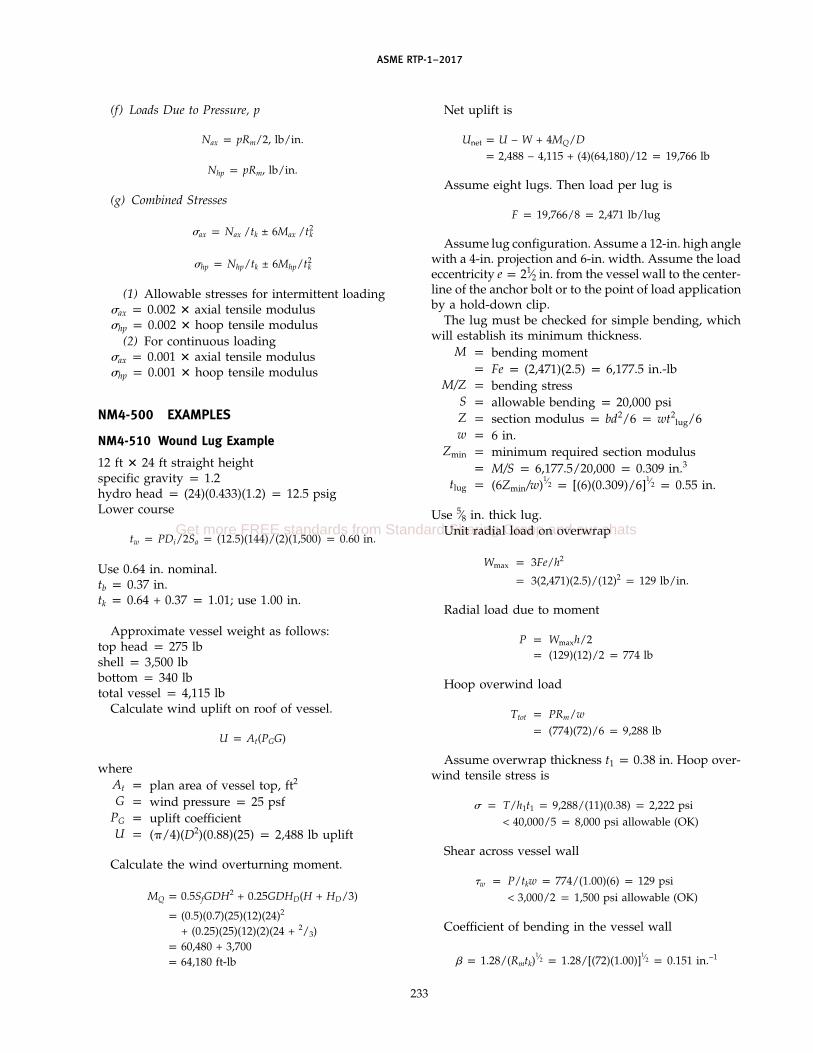
ASME RTP-1–2017
(f) Loads Due to Pressure, p
Nax p pRm/2, lb/in.
Nhp p pRm, lb/in.
(g) Combined Stresses
�ax p Nax /tk ± 6Max /t2k
�hp p Nhp/tk ± 6Mhp/t2k
(1) Allowable stresses for intermittent loading�ax p 0.002 � axial tensile modulus�hp p 0.002 � hoop tensile modulus
(2) For continuous loading�ax p 0.001 � axial tensile modulus�hp p 0.001 � hoop tensile modulus
NM4-500 EXAMPLES
NM4-510 Wound Lug Example
12 ft � 24 ft straight heightspecific gravity p 1.2hydro head p (24)(0.433)(1.2) p 12.5 psigLower course
tw p PDi/2Sa p (12.5)(144)/(2)(1,500) p 0.60 in.
Use 0.64 in. nominal.tb p 0.37 in.tk p 0.64 + 0.37 p 1.01; use 1.00 in.
Approximate vessel weight as follows:top head p 275 lbshell p 3,500 lbbottom p 340 lbtotal vessel p 4,115 lb
Calculate wind uplift on roof of vessel.
U p At(PGG)
whereAt p plan area of vessel top, ft2
G p wind pressure p 25 psfPG p uplift coefficientU p (�/4)(D2)(0.88)(25) p 2,488 lb uplift
Calculate the wind overturning moment.
MQ p 0.5SfGDH2 + 0.25GDHD(H + HD/3)
p (0.5)(0.7)(25)(12)(24)2
+ (0.25)(25)(12)(2)(24 + 2/3)p 60,480 + 3,700p 64,180 ft-lb
233
Net uplift is
Unet p U − W + 4MQ/Dp 2,488 − 4,115 + (4)(64,180)/12 p 19,766 lb
Assume eight lugs. Then load per lug is
F p 19,766/8 p 2,471 lb/lug
Assume lug configuration. Assume a 12-in. high anglewith a 4-in. projection and 6-in. width. Assume the loadeccentricity e p 21⁄2 in. from the vessel wall to the center-line of the anchor bolt or to the point of load applicationby a hold-down clip.
The lug must be checked for simple bending, whichwill establish its minimum thickness.
M p bending momentp Fe p (2,471)(2.5) p 6,177.5 in.-lb
M/Z p bending stressS p allowable bending p 20,000 psiZ p section modulus p bd2/6 p wt2
lug/6w p 6 in.
Zmin p minimum required section modulusp M/S p 6,177.5/20,000 p 0.309 in.3
tlug p (6Zmin/w)1⁄2 p [(6)(0.309)/6]
1⁄2 p 0.55 in.
Use 5⁄8 in. thick lug.Unit radial load on overwrap
Wmax p 3Fe/h2
p 3(2,471)(2.5)/(12)2 p 129 lb/in.
Radial load due to moment
P p Wmaxh/2p (129)(12)/2 p 774 lb
Hoop overwind load
Ttot p PRm/wp (774)(72)/6 p 9,288 lb
Assume overwrap thickness t1 p 0.38 in. Hoop over-wind tensile stress is
� p T/h1t1 p 9,288/(11)(0.38) p 2,222 psi< 40,000/5 p 8,000 psi allowable (OK)
Shear across vessel wall
�w p P/tkw p 774/(1.00)(6) p 129 psi< 3,000/2 p 1,500 psi allowable (OK)
Coefficient of bending in the vessel wall
p 1.28/(Rmtk)1⁄2 p 1.28/[(72)(1.00)]
1⁄2 p 0.151 in.−1
Get more FREE standards from Standard Sharing Group and our chats

ASME RTP-1–2017
Unit radial loading is
P* p P/w p 774/6 p 129 lb/in.
Axial and hoop bending loads
Max p P*/4 p 129/(4)(0.151) p 213.6 in.-lb/in.
Mhp ≅ Max p (0.3)(213.6) p 64 in.-lb/in.
Axial load due to pressure
Nax p pRm/2
However, p p 0 for no pressure above the liquid(atmospheric vessel). Therefore, Nax p 0.
Hoop load due to pressure
Nhp p pRm
wherep p 12.5 psig hydrostatic (hoop direction)
Nhp p (12.5)(72) p 900 lb/in.
Axial and hoop stresses
�ax p Nax/tk + 6Max/t2k
p 0 + (6)(213.6)/(100)2 p 1,281.6 psi
�hp p Nhp/tk + 6Mhp/t2k
p 900/1.00 + (6)(64)/(1.00)2 p 1,284 psi
NM4-520 Secondary Bonded Lug Example
Using the same example problem as in para. NM4-510,assume a lug attached by secondary bonding is electedfor use.
Again assume eight lugs with an uplift load of2,471 lb/lug � 8 p 19,768 lb total.
Assume the same lug geometry as before, and checkthe required minimum lug height. Lug width to vesseldiameter ratio w/Do p 6/145.6 p 0.041. FromFig. NM4-3, assuming eight lugs, ML p 0.024.
h p �6DoWeML
NSat2k
�1⁄2
p �(6)(145.6)(19,768)(2.5)(0.024)
(8)(1,500)(1.0)2 �1⁄2
p 9.28 in. (min.)
For simplicity and to permit comparison, again use12 in. high lug, 6 in. wide.
As before, check the lug for simple bending to estab-lish its minimum thickness.
Unit radial load on overwrap
Wmax p 3Fe/h2 p (3)(2,471)(2.5)/(12)2 p 129 lb/in.
234
Total radial load due to lug moment
P p Wmaxh/2 p (129)(12)/2 p 774 lb
Next calculate the tensile perimeter
2h1 + w p (2)(11) + 6 p 28 in.
The tensile perimeter load p P/tensile perimeter p774/28 p 27.6 lb/in. < 50 lb/in.
The minimum required area of secondary RTP bondoverlay on the vessel wall, or the area of overlay on theupstanding leg of the lug below the retainer bar requiredfor shear, shall be not less than
AR p W/200N p 19,768/(200)(8) p 12.4 in.2/lug
Proceeding as before, the overlay hoop load is
Ttot p PRm/w p (774)(72)/6 p 9,288 lb
The overlay hoop tensile stress, assuming overlaythickness t1 p 0.38 in., is
� p Ttot/h1t1 p 9,288/(11)(0.38)p 2,222 psi < 3,000 psi
Shear across vessel wall
�w p P/tkw p 774/(1.0)(6) p 129 psi
Coefficient of bending in vessel wall
p 1.28/(Rmtk)1⁄2 p 128/[(72)(1.0)]
1⁄2
p 0.151 in.−1
Unit radial loading
p* p P/w p 774/6 p 129 lb/in.
Bending loads
Max p P*/4 p 129/(4)(0.151) p 213.6 in.-lb/in.
Mhp ≅ Max p (0.3)(213.6) p 64 in.-lb/in.
Since the overlay is not a full circumferential winding,all stresses due to internal pressure and/or hydrostatichead are presumed to be taken by the vessel shell itself.Thus, the bending stresses in the overwrap are due onlyto the bending loads introduced by the lug.
Bending stresses
�ax p 6Max/t21 p (6)(213.6)/(0.38)2 p 8,875 psi
�hp p 6Mhp/t21 p (6)(64)/(0.38)2 p 2,659 psi

ASME RTP-1–2017
Since these stresses are much too high, the thickness ofthe overwrap must be increased. Try 1.0 in.
�ax p 6Max/t21 p (6)(213.6)/(1.0)2 p 1,281.6 psi
�hp p 6Mhp/t21 p (6)(64)/(1.0)2 p 384 psi
If we set a stress limit of Sa for loads due to uplift,we can solve directly for the overlay thickness t1. Usethe greater of
t1min p 6Max/Sa
235
or
t1min p 6Mhp/Sa
It can thus be seen that the required overlay thicknessis approximately equal to the vessel wall at the bottomknuckle region. The use of more hold-down lugs wouldreduce the load per lug. This may not be cost effective,however, since more anchor bolts are required.
Get more FREE standards from Standard Sharing Group and our chats
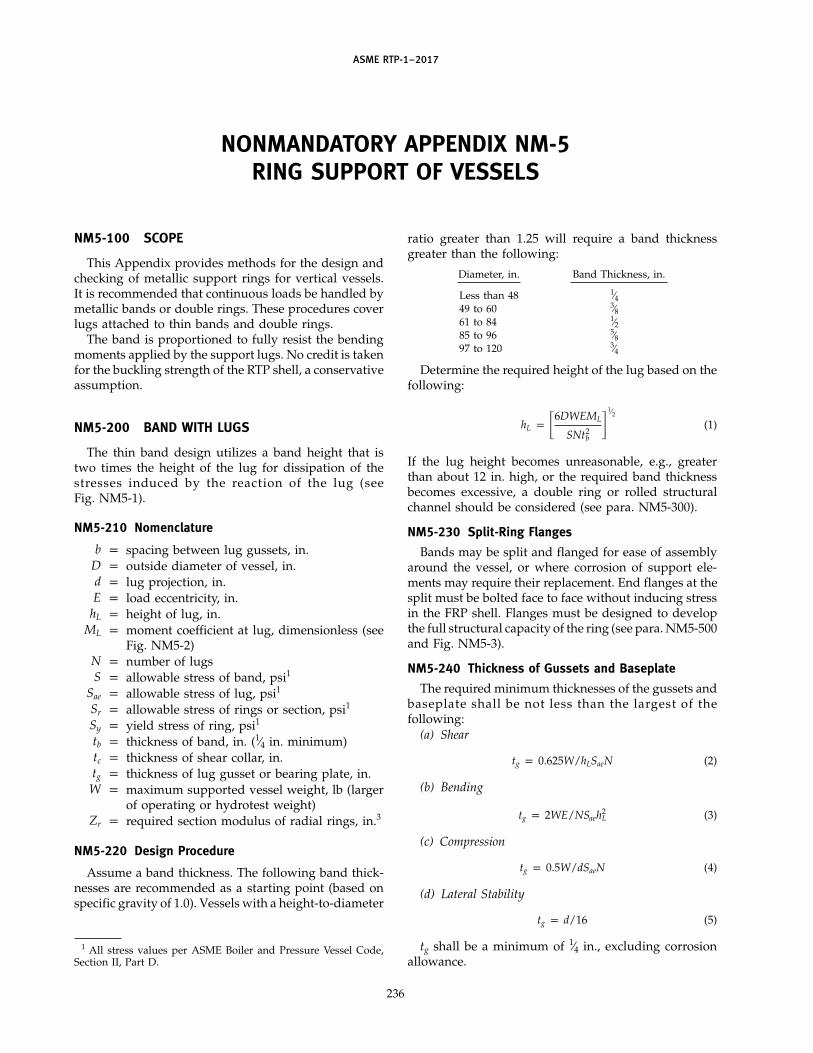
ASME RTP-1–2017
NONMANDATORY APPENDIX NM-5RING SUPPORT OF VESSELS
NM5-100 SCOPE
This Appendix provides methods for the design andchecking of metallic support rings for vertical vessels.It is recommended that continuous loads be handled bymetallic bands or double rings. These procedures coverlugs attached to thin bands and double rings.
The band is proportioned to fully resist the bendingmoments applied by the support lugs. No credit is takenfor the buckling strength of the RTP shell, a conservativeassumption.
NM5-200 BAND WITH LUGS
The thin band design utilizes a band height that istwo times the height of the lug for dissipation of thestresses induced by the reaction of the lug (seeFig. NM5-1).
NM5-210 Nomenclature
b p spacing between lug gussets, in.D p outside diameter of vessel, in.d p lug projection, in.E p load eccentricity, in.
hL p height of lug, in.ML p moment coefficient at lug, dimensionless (see
Fig. NM5-2)N p number of lugsS p allowable stress of band, psi1
Sae p allowable stress of lug, psi1
Sr p allowable stress of rings or section, psi1
Sy p yield stress of ring, psi1
tb p thickness of band, in. (1⁄4 in. minimum)tc p thickness of shear collar, in.tg p thickness of lug gusset or bearing plate, in.
W p maximum supported vessel weight, lb (largerof operating or hydrotest weight)
Zr p required section modulus of radial rings, in.3
NM5-220 Design Procedure
Assume a band thickness. The following band thick-nesses are recommended as a starting point (based onspecific gravity of 1.0). Vessels with a height-to-diameter
1 All stress values per ASME Boiler and Pressure Vessel Code,Section II, Part D.
236
ratio greater than 1.25 will require a band thicknessgreater than the following:
Diameter, in. Band Thickness, in.
Less than 48 1⁄449 to 60 3⁄861 to 84 1⁄285 to 96 5⁄897 to 120 3⁄4
Determine the required height of the lug based on thefollowing:
hL p �6DWEML
SNt2b
�1⁄2
(1)
If the lug height becomes unreasonable, e.g., greaterthan about 12 in. high, or the required band thicknessbecomes excessive, a double ring or rolled structuralchannel should be considered (see para. NM5-300).
NM5-230 Split-Ring Flanges
Bands may be split and flanged for ease of assemblyaround the vessel, or where corrosion of support ele-ments may require their replacement. End flanges at thesplit must be bolted face to face without inducing stressin the FRP shell. Flanges must be designed to developthe full structural capacity of the ring (see para. NM5-500and Fig. NM5-3).
NM5-240 Thickness of Gussets and Baseplate
The required minimum thicknesses of the gussets andbaseplate shall be not less than the largest of thefollowing:
(a) Shear
tg p 0.625W/hLSaeN (2)
(b) Bending
tg p 2WE/NSaeh2L (3)
(c) Compression
tg p 0.5W/dSaeN (4)
(d) Lateral Stability
tg p d/16 (5)
tg shall be a minimum of 1⁄4 in., excluding corrosionallowance.

ASME RTP-1–2017
Fig. NM5-1 Lugs on Band
3 in. min.
2 in. min.
Band
Shear collar
Overlay
Tank shell
Mat-resinfiller(optional)
Resin putty
Band support
tb
tc
hL
E hL/2
2hL
1/8 in. gap
tc = tb + 3/8 in.
237
Get more FREE standards from Standard Sharing Group and our chats

ASME RTP-1–2017
Fig. NM5-2 Moment Coefficient, ML
b/D
ML
ML =
N = number of lugs
= angle of b/D expressed in radians
−12
N2 2
0.10 0.15 0.20 0.250.05
0.06
0.08
0.02
0
0.04
0.10
0.12
0.14
0.16
0.00
N = 8
N = 2
N = 3
N = 4
12 N
cos +θ sin θ
θ
θπ
πsin θ − cot
238

ASME RTP-1–2017
Fig. NM5-3 Split-Ring Flange
Flange weldmust befull penetration
Fabrication Options
c = bolt hole diameterMinimum
1.5c
f [Note (1)]
Center ofshear
NOTE:(1) If f exceeds 8 in., add an additional bolt at midspan to stabilize the flange. Do not include in Nb, number of bolts.
a
r
tf (3/8 in. min.)
tb
h
239
Get more FREE standards from Standard Sharing Group and our chats

ASME RTP-1–2017
The minimum leg size of the continuous fillet weldsattaching the gussets and base to the band shall equal1.4tg.
NM5-250 Shear Collar
Shear collar height shown in Fig. NM5-1 is minimum.Actual shear and compressive stresses shall be calcu-lated. Shear collar heights and thicknesses shall be com-pared to minimums shown and increased as necessary.
NM5-300 DOUBLE-RING SUPPORT
Double-ring supports are a method of providing sup-ports of reasonable proportions where the loads and/orlug eccentricities are large. The support is comprised ofa channel fabricated of two continuous rings or a rolledstructural channel (see Fig. NM5-4). This support ringis proportioned to resist all bending and torsional loadswithout introducing any significant local loads into theFRP shell.
This paragraph provides a method for checking thestress in a support ring of a vertical vessel. The procedureis limited to thin ring beams with three or more evenlyspaced lugs. Thin rings are those whose thickness in theradial direction is less than one-tenth their radius.
Double rings support the vessel by means of a shearcollar.
NM5-310 Nomenclature
b p spacing between lug gussets, in.D p outside diameter of vessel, in.d p radial projection of ring or channel from web
or band, in.E p load eccentricity from centerline web to cen-
terline anchor bolt, in.e p eccentricity of support reaction force, in. (see
Fig. NM5-4)e* p location of center of torsional shear from cen-
terline of web or band, in.h p height of ring section, in.
hb p height of band, in.p h + 1
I p moment of inertia of ring section about acentroid axis in the plane of the ring, in.4
J p torsional stiffness constant of ring section, in.4
Mb p bending moment at a section of ring, in.-lbML p moment coefficient at lugs, dimensionlessMt p twisting moment at a section of ring, in.-lbN p number of lugsR p inside radius of double-ring support, in.Sr p allowable stress of ring or section, psi2
tb p thickness of band, in. (1⁄4 in. minimum)tc p thickness of shear collar, in.tg p thickness of gusset, in.tr p thickness of ring, in.tw p thickness of web, in.W p total load supported by ring, lb
240
Zb p bending section modulus, in.3
Zr p required section modulus of each ring, in.3
Zt p torsional section modulus, in.3
� p angle defined in Fig. NM5-5, rad�– p normalized stress, dimensionless
�b p bending stress, psi�vm p Von-Mises stress defined below, psi
� p torsional stress, psi� p angle defined in Fig. NM5-5, rad
NM5-320 Design Procedure for Double Rings on aBand
A double-ring support may be fabricated by addingtwo rings to a steel band. The vessel is supported by ashear collar, in this case bearing on the top of the steelsupport band [see Fig. NM5-4, sketch (a)].Step 1: Assume a desired ring height and gusset
spacing. Since the vessel diameter, supporteccentricity, weight, and desired number ofsupport points are known, an approximatesection modulus for the ring can be calculated
Zr pDWeML
NhSr(6)
This is the estimated minimum sectionmodulus for each of two rings mounted ona steel band. The resulting double ring mustbe checked for bending and torsional stressesas follows.
Step 2: Determine the location of the center of shear,e*. This must be added to the projection ofthe lug, E, from the centerline of the bolt holeto the centerline of the web to obtain the totaleccentricity, e, for the double-ring support.
For double rings on a band [see Fig. NM5-4,sketch (a)]
e* pd2(h − tr)2tr
4I(7)
e p e* + E
Step 3: Determine the ratio e/R.Step 4: Calculate Zb. For double rings on a band [see
Fig. NM5-4, sketch (a)]
Zb ptb(h3
b) + d[h3 − (h − 2tr)3]6hb
(8)
Step 5: For double rings on a band per Fig. NM5-4,sketch (a)
J pt3r(2d)
3+
t3b(hb)
3(9)

ASME RTP-1–2017
Fig. NM5-4 Ring Support of Vessels
Shearcollar
Center oftorsionalshear
Projectionof band =tb + 1/2 in.
tc = tw + 3/8 in.tc = tb + 3/8 in.
h ≥ 3d
Mat-resin filler(optional)
Lugextension
(a) Double Rings
on a Band
Ring/bandsupport
Lugextension
(b) Rolled Structural
Ring Without Band
tb
tc
tr (typical)
tr (typical)
3 in. min.
2 in. min.
E
R
d
h
Ee*
e
Center oftorsionalshear
tc
d
tw
R
h
e*
e
1/8 in. gap
1/8 in. gap
241
Get more FREE standards from Standard Sharing Group and our chats
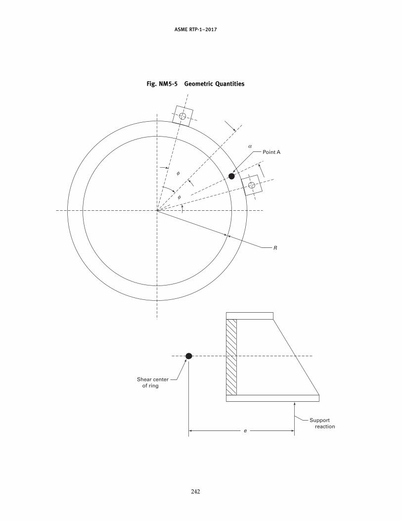
ASME RTP-1–2017
Fig. NM5-5 Geometric Quantities
Shear centerof ring
Supportreaction
e
φ
α
φ
Point A
R
242

ASME RTP-1–2017
Step 6: Calculate Zt.
Zt p J/tb
Step 7: Calculate the ratio Zb/Zt.Step 8: Use Figs. NM5-6 through NM5-8 for the
applicable number of support points anddetermine �–.
Step 9: From this, calculate the maximum combinedstress due to bending and torsion, theVon-Mises stress
�vm p WR�/Zb (10)
Step 10: Check gusset thickness per para. NM5-240.
NM5-400 DESIGN PROCEDURE FOR A FABRICATEDOR ROLLED STRUCTURAL CHANNELDOUBLE-RING SUPPORT
A double-ring support can also be in the form of afabricated or rolled structural channel.
With a rolled structural channel, the shear collar ofthe vessel rests directly on the top flange [see Fig. NM5-4,sketch (b)].
NM5-410 Stress in Ring
The bending and twisting moments at a point A (seeFig. NM5-5) in the ring are given by
Mb p−WR
2� �� cos �sin �
− 1 −�eR
sin (� − �)� (11)
Mt pWR2� �� sin �
sin �− � −
�eR
cos (� − �)� (12)
where� p �/N
The bending stress is then given by
�b p Mb/Zb (13)
and the torsional stress by
� p Mt/Zt (14)
They can be combined in the Von-Mises stress
�vm p (�2b + 3�2)
1⁄2 (15)
The Von-Mises stress intensity must be no greater thanthe allowable stress intensity at every point on the ring.
To use eqs. (11) through (15) to check the ring design,it is necessary to calculate �vm at a number of locations(values of �) to be sure that the maximum stress hasbeen considered. Depending on the relative values of E,
243
R, and the ring section, the maximum may occur at anylocation.
NM5-420 Design Charts
Paragraph NM5-410 provides a basis for a computerprocedure for ring design, but is tedious to use for handcomputation. A set of charts that are derived from theequations in para. NM5-410 and cover most cases ofinterest is provided (see Figs. NM5-6 through NM5-8).
Procedure. Use the procedure of para. NM5-320, substi-tuting h for hb.
NM5-430 Section Proportions
Rings are often built from plate and welded togetherso that the cross sections are not standard structuralshapes. It is important that nonstandard shapes be elas-tically stable under loadings that paras. NM5-410 orNM5-420 allow. For this reason, the section proportionsshould satisfy section 1.5.1.4 of the AISC Specification.2
NM5-500 SPLIT-RING CONSTRUCTION
In many cases, rings are fabricated in two semicircularparts that are bolted around the vessel; thus, there willbe splices in the ring. These splices must be strongenough to develop the full strength of the ring in bothbending and twisting.
NM5-510 Nomenclature
Ab p area of one bolt, in.2
a p radial distance from band to bolt hole, in. (seeFig. NM5-3)
b p effective width of flange, in.p 3c
c p bolt hole diameter, in.e p eccentricity or lug reaction force, in.f p vertical distance between bolts, in.
Mb p moment in ring due to bending, in.-lbMf p moment on flange due to bolt load, in.-lbMt p moment in ring due to torsion, in.-lbNb p number of bolts p 2 (see Fig. NM5-3)
r p distance from ring center of shear to bolt hole(see Fig. NM5-3)
Sa p allowable stress, psitf p thickness of flange, in.
Zmin p minimum section modulus of effective widthof flange, in.3
NM5-520 Design Procedure
Equations (11) and (12) of para. NM5-410 provide thebending and torsional moments for any point on thering. On the basis of duplicate ring sections and simpli-fied design, it is recommended that splice flanges belocated midway between support points.
2 Manual of Steel Construction, American Institute of SteelConstruction, 1 East Wacker Drive, Chicago, IL 60601.
Get more FREE standards from Standard Sharing Group and our chats

ASME RTP-1–2017
Fig. NM5-6 Ring Design Chart for Three Lugs
2.0
1.5
2.0
0.5
1.0
2.5
3.0
3.5
0.0 4.0 6.0 8.0 10.0 12.0 14.0 16.0 18.0 20.0
0.000
0.050
0.100
0.150
0.200
0.250
0.300
0.350
0.400
0.450
0.500e/R
Bending Modulus / Torsion Modulus, Zb/Zt
No
rmal
ized
Str
ess,
σ
244

ASME RTP-1–2017
Fig. NM5-7 Ring Design Chart for Four Lugs
2.0
0.75
1.00
0.25
0.50
1.25
1.50
1.75
2.00
2.25
2.50
0.0 4.0 6.0 8.0 10.0 12.0 14.0 16.0 18.0 20.0
0.000
0.050
0.100
0.150
0.200
0.250
0.300
0.350
0.400
0.450
0.500e/R
Bending Modulus / Torsion Modulus, Zb/Zt
No
rmal
ized
Str
ess,
σ
245
Get more FREE standards from Standard Sharing Group and our chats

ASME RTP-1–2017
Fig. NM5-8 Ring Design Chart for Eight Lugs
2.0
0.3
0.4
0.1
0.2
0.5
0.6
0.7
0.8
0.9
1.1
1.0
0.0 4.0 6.0 8.0 10.0 12.0 14.0 16.0 18.0 20.0
0.000
0.050
0.100
0.150
0.200
0.250
0.300
0.350
0.400
0.450
0.500e/R
Bending Modulus / Torsion Modulus, Zb/Zt
No
rmal
ized
Str
ess,
σ
When splice flanges are located midway between thesupport points, the above-referenced equations arereduced to the following simplified formulas:
For four support points
Mb p W(−0.0176R + 0.0884e) (16)
Mt p 0.0884We (17)
For eight support points
Mb p W(−0.00417R + 0.0239e) (18)
Mt p 0.0557We (19)
NM5-521 ProcedureStep 1: Determine the maximum bending and tor-
sional moments in the ring at the location ofthe flanged split.
Step 2: Develop an assumed flange configuration (seeFig. NM5-3).
Step 3: Assume a bolt location.Step 4: Size the bolts based on bending (tension) or
torsion (shear), whichever controls (minimumbolt size shall be 5⁄8-in. nominal diameter).
Step 5: Calculate the flange thickness based on thebending (tensile) bolt load (calculated as a
246
cantilevered beam of width 3c and loaded atthe end by the tensile bolt load due to bendingof the ring).
NM5-522 Bolt Sizing(a) Bending
bolt load (tensile) p Mb/f, lb (20)
Bolt stress p (2)(bolt load)/NbAb, psi ≤ ASME Boilerand Pressure Vessel Code allowable (Section VIII,Division 1).
(b) Torsion
bolt load (shear) p Mt/r, lb (21)
Bolt stress p bolt load/NbAb, psi ≤ 0.5 ASME Boiler andPressure Vessel Code allowable (Section VIII,Division 1).
(c) Flange thickness on cantilevered flange
Mf p bolt load (tensile) � a (22)
Zmin p Mf/Sa (23)
Z p bt2f /6
b p 3c

ASME RTP-1–2017
Therefore
tf (min.) p (2Zmin/c)1⁄2 ≥ 3⁄8 in. (24)
NM5-530 Welding
All welding shall be continuous. All butt welds shallbe full penetration. Welding shall conform to theAmerican Welding Society D1.1 Structural WeldingCode.
NM5-600 EXAMPLESNM5-610 Double-Ring Support
Consider a 10-ft diameter vessel containing 126,000 lbof liquid with eight lugs having an eccentricity of 4.5 in.,e p 6.2 in., and a lug projection of 6 in. The candidatecross section is shown in Fig. NM5-9. The ring is to befabricated of steel with an allowable ASME Code stressof 25,000 psi.Step 1: N p 8Step 2: e/R p 6.2/61 p 0.1Step 3: Zb p 58.5 in.3; Zt p 3.94 in.3; Zb/Zt p 14.8Step 4: From the chart for eight lugs, � p 0.18Step 5: Assuming that the vessel itself would weigh
5% as much as the contents, the entire sup-ported weight is 132,400 lb.
�vm p WR�/Zb
p (132,400)(61)(0.18)/58.5 p 24,850 psi
Thus, the stress intensity is less than theallowable stress and the section chosen is ade-quate.
Step 6: Using para. NM5-240, calculate the requiredminimum gusset thickness. Equation (5) givesthe maximum value of tg p 6/16 p 3⁄8 in.
NM5-620 Band With Lugs
Assume a 10-ft diameter � 10-ft straight-side vessel.Use a specific gravity of 1.2 and a lug load eccentricity,E, of 3 in. Assume eight lugs (see Fig. NM5-10). Thelower head is ASME flanged and dished. The floodedweight of the vessel is approximately 67,000 lb.
Try a band with lugs, similar to Fig. NM5-1. For the10-ft diameter, the band will be 3⁄4 in. thick.
Calculate the required lug height. Assume b p 6 in.Then b/D p 6/122 p 0.05. ML p 0.022.
hL p �6DWEML
SNt2b
�1⁄2
p �(6)(122)(67,000)(3)(0.022)
(12,700)(8)(0.75)2 �1⁄2
p 7.52 in.
Use 8 in. high lugs on a 16 in. high � 3⁄4 in. thick band.
247
NM5-630 Split-Ring Flange
Develop a flange for splitting the ring in the previousexample. This is a 3⁄4 in. thick � 16 in. high ring ona 10-ft nominal diameter vessel. The filled weight is67,000 lb. Assume eight lugs. From the previous example
E p 3 in.e p 3.75 in.
R p 61 in.W p 67,000 lb
Referencing Fig. NM5-3, assumea p 1.875 in.c p 0.625 in.f p 14 in.r p 71⁄4 in.
(a) Determine Moments(1) Moment due to bending
Mb p W(−0.00417R + 0.0239e)p 67,000(−0.2544 + 0.090)p −11,015 in.-lb
(2) Moment due to torsion
Mt p 0.0577Wep (0.0577)(67,000)(3.75)p 14,497 in.-lb
(b) Bolt Sizing(1) Bending
bolt load p Mb/f p 11,015/14 p 786.8 lb (tension)
Assume 5⁄8 in. bolt; Ab p 0.202 in.2 Then
bolt stress (tension) p (2)(786.8)/(2)(0.202)p 3,895 psi< 25,000 psi for B7 bolts
(2) Torsion
bolt load p Mt/r p 14,497/7.25 p 2,000 lb (shear)
bolt stress p 2,000/(2)(0.202) p 4,950 psi < 25,000/2 psi
(3) Flange thickness on cantilevered flange
Mf p bolt load (tensile) � ap (786.8)(1.875) p 1,475 in.-lb
Zmin p 1,475/12,700 p 0.116 in.3
tf p [(2)(0.116)/0.625]1⁄2
p 0.609 in. (use 11⁄16 in. minimum)
Get more FREE standards from Standard Sharing Group and our chats

ASME RTP-1–2017
Fig. NM5-9 Example Cross Section
15
0.75 (typical)3.75
I =
J =
+ 2(7.5 − 0.375)2(3.75)(0.75) = 439.3 in.4
(3.75)(0.75)3 +13 (13.5)(0.75)3 +1
3 (3.75)(0.75)3 = 2.95 in.413
0.75(13.5)3
13
Zb = = 58.5 in.3439.37.5
Zt = = 3.94 in.32.950.75
248

ASME RTP-1–2017
Fig. NM5-10 Lug
tg
tg
E
1 in. min.
tg
hL
b
d c
249
Get more FREE standards from Standard Sharing Group and our chats

(17)
ASME RTP-1–2017
NONMANDATORY APPENDIX NM-6EXAMPLE OF A FABRICATOR’S QUALITY CONTROL PROGRAM
This Appendix shows one example of a Fabricator’sQuality Control Program. It is written with mandatorylanguage to illustrate the proper terminology for sucha program.
NOTE: Refer to Mandatory Appendices M-1 and M-2 andNonmandatory Appendix NM-7 for tables from those appendicesthat are referenced here.
Table of Contents
Section Title
1 Quality Control Policy2 Quality Control Organization3 Documentation4 Inspection of Received Goods5 In-Process Inspection6 Finished Equipment Inspection7 Record Retention and Controls
SECTION 1 QUALITY CONTROL POLICY
1.1 Scope
This policy establishes the requirements, systems, andprocedures for the Quality Assurance Program.
1.2 Purpose
The purposes of the Quality Assurance Program areas follows.
1.2.1 Ensure adherence to the rules and require-ments of ASME RTP-1 through correct and thoroughprocessing of purchase orders, drawings, specifications,and other documents.
1.2.2 Establish an inspection system to monitorthe variability of workmanship, processes, and materialsin order to produce a consistent, uniform product.
1.2.3 Establish and monitor the quality require-ments related to materials and services of Vendors orSubcontractors based on surveillance and performanceanalysis.
1.2.4 Provide a system for the detection of defecttrends and institute corrective measures.
1.3 Laboratory Standards
1.3.1 A laboratory standards program shall bemaintained for the calibration of the measuring and testequipment.
250
1.3.2 The program shall provide confidence in theaccuracy of the measuring and test equipment.
1.4 Test Methods
Specific written inspection and test procedures shallbe followed for all inspection and test operations.
1.5 Operating Procedures
1.5.1 Parts shall be made in the sequence and bythe conditions specified in the Fabricator’s operatingprocedures.
1.5.2 These production procedures shall be avail-able to Quality Control personnel during their audits soas to confirm adherence to them.
1.6 Documentation
1.6.1 Inspection results shall be documented andkept on file for 5 yr or as specified by contractual require-ments, whichever is longer.
1.6.2 Inspection documentation shall be by refer-ence to shop order number, part number, or in any man-ner that will link inspection results with a specific part.
1.6.3 Only approved forms shall be used for theentering of inspection results, as well as for such relateditems as the purchasing of raw materials, processingorders, and subcontracting work on orders.
1.6.4 Any change in documentation shall beapproved by QC Management.
1.6.5 To ensure that the latest revision of eachdocument is recorded and used during the fabricationprocess, Engineering shall maintain, update, and distrib-ute the Document Control Sheet (Table NM6-3), at inter-vals not to exceed 7 days.
1.7 Nonconformity Correction Reports
1.7.1 When nonconformities or imperfectionsrequiring correction are discovered, a NonconformityCorrection Report, Table NM6-6 (copy attached), shallbe initiated by the Quality Control Department.
1.7.2 The report shall be forwarded to Engineeringto determine the cause of the nonconformity and toinitiate proper corrective action.
1.7.3 The determination shall include(a) manufacturing and processing procedures

ASME RTP-1–2017
(b) purchase orders(c) results of tests
1.7.4 The report shall be reviewed and approvedby the QC Manager, who shall also secure all otherreviews and approvals as required by MandatoryAppendix M-7 of ASME RTP-1.
1.8 Distribution of QC Manual
1.8.1 The manual shall be distributed, as necessary,by the QC Manager.
1.8.2 Distribution of these manuals is limited, andeach copy shall be numbered.
1.9 QC Manual Revision
1.9.1 The manual shall be revised, as necessary,by the QC Manager, subject to review and approval ofthe General Manager.
1.9.2 The manual index shall also be periodicallyupdated by the QC Manager.
1.9.3 Manual updating shall be done by all holdersupon receipt of a revised section, and the supersededparts shall be destroyed.
1.9.4 The QC Manager shall maintain a masterrecord of all manual revisions (see Table NM6-7).
1.10 Notification of In-Process Changes
1.10.1 Initiator shall notify all responsible partiesin writing or verbally with written confirmation,depending on the impact of the change.
1.10.2 Changes require Engineering approvalbefore implementation.
1.10.3 Necessary documentation shall be changedand clearly marked.
SECTION 2 QUALITY CONTROL ORGANIZATION
2.1 Scope and Purpose
This section sets forth the following:
2.1.1 The organization of the Quality ControlDepartment.
2.1.2 The definition of the responsibilities andauthorities associated with each job.
2.1.3 The relationship of each job to other jobswithin the organization.
2.2 Organizational Responsibility
2.2.1 General Management is responsible for theestablishment and maintenance of an adequate QualityControl Program.
251
2.2.2 Additional personnel outside of the QCDepartment may be assigned to act in various qualitycontrol functions.
2.2.3 Where inspection is done by non-QC person-nel, audits of the effectiveness of their work shall beperiodically performed by QC.
2.3 Organizational Functions
2.3.1 The total quality function encompasses manyactivities and personnel, but it is the function of QApersonnel to ensure conformance to specifications.
These functions include(a) design review of applicable drawings(b) inspection of incoming raw materials and
components(c) providing control at various stages of processing
and fabricating(d) determining product release or rejection
2.3.2 QC Management shall analyze rejection deci-sions. It may finalize the decision or make changes underpermitted repair procedures.
2.4 Organization Chart
See Fig. NM6-1.
SECTION 3 DOCUMENTATION
3.1 Scope and Purpose
3.1.1 This section establishes the minimum docu-mentation required for quality control during fabricationof RTP equipment.
3.1.2 Adequate and meticulous documentation isthe foundation of a good Quality Control Program.
3.2 Minimum Documentation
See Document Distribution List, Table NM6-4.
3.3 Document Preparation Responsibility
See Documentation Preparation and DistributionResponsibility, Table NM6-5 (copy attached).
SECTION 4 INSPECTION OF RECEIVED GOODS
4.1 Resin
The results of the following shall be recorded on theResin Log Sheet, Table M2F-1, prior to use in fabrication.
4.1.1 The resin shall be checked to ensure it is theproduct ordered.
4.1.2 The resin shall have the proper label for thespecified product, including the manufacturer’s productname and Manufacturer’s Specific Product Identification(MSPI).
Get more FREE standards from Standard Sharing Group and our chats

AS
ME
RTP-1–2017
Fig. NM6-1 Organization Chart
PlantSupt.
EngineeringManager
QualityControl
Manager
PlantController/Purchasing
MarketingManager
Salesmen SalesReps.
CostAccountant
Bookkeeper Inspector(s) ResinMixing &Control
Receiving &Materials
Issue
GeneralManager
Receptionist
Laboratory
Drafting Estimating
Molds,Maintenance
& Tooling
ProductionControl
1stShift
2ndShift
Tool Crib
FieldServices
CertifiedIndividual
[See Note (1)]
NOTE:(1) Refer to para. 1-400 for specific responsibilities.
252
ASME RTP-1–2017
4.1.3 The resin shall be visually checked to be oftypical color and clarity for the specific resin, free fromsolid or gelled particles.
4.1.4 The resin shall be within the manufacturer’sspecified limits for specific gravity, viscosity, and roomtemperature gel time as determined by the test methodsof Mandatory Appendix M-2, Articles B through E, ofASME RTP-1.
4.1.5 Material certification and/or Certificates ofCompliance where applicable shall be checked againstthe MSPI.
4.1.6 The storage environment of the resin shallbe in compliance with the manufacturer ’srecommendations.
4.2 Reinforcements
The results of the following shall be recorded on LogSheets, Tables M1A-1, M1B-1, M1C-1, and M1D-1, priorto use in fabrication.
4.2.1 The reinforcement shall be checked to ensureit is the product ordered.
4.2.2 The reinforcement shall have the proper label,including the manufacturer’s product name and theMSPI.
4.2.3 The reinforcement package shall be checkedfor damage.
4.2.4 Material certification and/or Certificates ofCompliance where applicable shall be checked againstthe MSPI.
4.2.5 The storage environment of reinforcementsshall be in compliance with the manufacturer ’srecommendations.
4.3 Curing Agents
The results of the following shall be recorded on theCuring Agents Log Sheet, Table M2F-2, prior to use infabrication.
4.3.1 Curing agents shall be checked to ensurethey are the products ordered.
4.3.2 Curing agents shall have the proper labelfor the specified product, including the manufacturer’sname and the MSPI.
4.3.3 Curing agents shall be visually checked toensure there is no stratification of the material in twoor more phases. In the case of liquids, they shall be freeof sediment or solid particles.
4.3.4 Curing activity of the curing agent shall bechecked using the test method outlined in MandatoryAppendix M-2, Article E, of ASME RTP-1.
253
4.3.5 The storage environment of curing agentsshall be in compliance with the manufacturer ’srecommendations.
4.4 Purchased and/or Subvended Items
4.4.1 The item(s) shall be checked to ensure thatit is the product ordered.
4.4.2 The item(s) shall be inspected for damage.
4.4.3 The item(s) shall be in compliance with theapplicable drawings, specifications, and test methodsthat are part of the Fabricator/Subvendor/Useragreement.
4.4.4 The item(s) shall be properly stored to ensureintegrity.
4.5 Common Additives
The results of the following shall be recorded on theCommon Additives Log Sheet, Table M2G-1, prior touse in fabrication.
4.5.1 Additives shall be checked to ensure theyare the product ordered.
4.5.2 Additives shall have the proper label for thespecified product, including the manufacturer’s productname and the MSPI.
4.5.3 Additive packaging shall be checked fordamage.
4.5.4 Additives shall be stored in an environmentthat complies with the manufacturer ’srecommendations.
SECTION 5 IN-PROCESS INSPECTION
5.1 Resin Mixing
The following data shall be recorded on the MixingData Sheet, Table NM6-1 (copy attached).
5.1.1 All resin mixing and primary preparationshall be done in one location under controlledconditions.
5.1.2 Formulas that have been predetermined foreach particular type of resin shall be kept in a logbookcontaining completed Mixing Data Sheets.
5.1.3 Mixing Data Sheets are also filled out foreach batch and kept in a separate log with reference tothe particular job number(s).
5.2 Material Dispersion
5.2.1 Resin shall be dispersed in containers thatare clearly marked, identifying their contents. Theseidentifying numbers must be transferred to theComponent Data Sheet, Table NM6-2 (copy attached),for the component utilizing that resin.
Get more FREE standards from Standard Sharing Group and our chats

ASME RTP-1–2017
5.2.2 Reinforcements shall be visually inspected,as they are dispersed, for imperfections (such as holes,cuts, thin spots, and separations) and contaminants(such as dirt, oil, grease, and foreign objects) under ade-quate overhead lighting. Dimensions, weights, and iden-tifying numbers shall be recorded on Log Sheets(Tables M1A-1, M1B-1, M1C-1, and M1D-1).
5.3 Component Fabrication
The following data shall be recorded on theComponent Data Sheet, Table NM6-2 (copy attached),prior to assembly.
5.3.1 As components are fabricated, the identifica-tion numbers of the materials used are recorded.
5.3.2 The lamination sequence of a particular com-ponent shall be recorded and verified to be correct.
5.3.3 On machine-made components, pertinentmachine settings shall be recorded.
5.3.4 Curing agent system and amount utilizedfor each component shall be recorded.
5.3.5 Barcol readings of fabricated componentsshall be taken and recorded.
5.4 Assembly
The following data shall be recorded on the InspectionChecklist, Table NM7-2: Throughout the assembly pro-cedure, proper sequences, materials, and dimensionsshall be verified.
SECTION 6 FINISHED EQUIPMENT INSPECTION
The following data shall be recorded on the InspectionChecklist, Table NM7-2.
6.1 Resin Cure
6.1.1 Surface hardness shall be checked in accor-dance with ASTM D2583. Random readings shall betaken on all parts and overlays. Certain corrosion barri-ers and cure systems may result in lower than typicalhardness. If this is anticipated, an adjusted Barcol hard-ness value shall be established with the User prior tofabrication.
6.1.2 All surfaces including overlays shall pass anacetone sensitivity test. This is done by rubbing severaldrops of acetone on a small area and allowing the ace-tone to evaporate. Tackiness indicates improper resincure.
6.1.3 All repairs to correct a nonconformity shallbe made in accordance with Mandatory Appendix M-7of ASME RTP-1.
6.2 Dimensions and Laminate Thickness
6.2.1 Thicknesses of all components and overlaysshall be checked in accordance with para. 6-920 of
254
ASME RTP-1. Thicknesses can be verified by measuringactual cutouts, where possible, or employing an ultra-sonic or magnetic gage.
6.2.2 All dimensions and locations shall bechecked against the equipment drawing and recorded.
6.2.3 All repairs to correct a nonconformity shallbe made in accordance with Mandatory Appendix M-7of ASME RTP-1.
6.3 Visual Imperfections
6.3.1 The entire fabrication shall be checked forvisual imperfections as described in Table 6-1 ofASME RTP-1. The equipment shall comply with theVisual Inspection Level that has been specified.
6.3.2 All repairs to correct an imperfection shallbe made in accordance with Mandatory Appendix M-7of ASME RTP-1.
6.4 Physical Property Tests
6.4.1 Reinforcement-to-resin ratio is establishedthrough loss by ignition testing in accordance withASTM D2584. Each component shall be tested if a cutoutor trim area is available.
6.4.2 Laminate proof tests on a cutout or endsample from the shell shall be done in accordance withASTM D638, ASTM D3039, or ASTM D5083. Valuesobtained shall be equal to or greater than those specifiedand used in design calculations.
6.5 Equipment Pressure Tests
6.5.1 See para. 6-950 of ASME RTP-1 for require-ments on pressure tests.
6.5.2 It is company safety policy that(a) a relief valve set at 2 psig to 3 psig above the
maximum test pressure be installed at the top of allvessels to be hydrotested under positive pressure
(b) prior to applying pressure, all air shall be dis-placed by water on vessels to receive a hydrotest at apositive pressure
(c) all vacuum tests shall be conducted outside theshop, behind substantial safety barriers
(d) the Quality Control Manager shall review andapprove all test setups for safety prior to applying pres-sure or vacuum
SECTION 7 RECORD RETENTION AND CONTROLS7.1 Scope
7.1.1 This procedure shall ensure that the recordsretained are complete and reliable.
7.1.2 Inspection and testing records shall, as aminimum, indicate the nature and number of observa-tions made, and the number and type of nonconformitiesfound.

ASME RTP-1–2017
7.1.3 Records shall be available for review as one ofthe principal forms of objective evidence of the QualityAssurance Program.
7.2 Application and Retention
7.2.1 In general, records shall be retained by theQuality Control Department.
7.2.2 These records shall be used basically to verifyproduct conformance. They shall indicate the acceptabil-ity of work or products and the action taken in connec-tion with nonconformities.
7.3 Record Retention
The Quality Control Department shall maintaininspection and test records of complete assembled unitsor subassemblies. These records shall be stored andmaintained for 5 yr.
7.4 Procedure for Record Handling
7.4.1 Records shall be filed primarily according toShop Order number.
7.4.2 For incoming inspection, records shall besubdivided according to part number or alphabeticallyaccording to the name of the supplier.
7.4.3 Serialized items for shipment to a customershall be filed sequentially. A separate file shall be main-tained to show dates of shipments of individual itemsor groups of serialized items.
255
7.4.4 Records of shipped items shall show partname, part number, and serial number of the product.This shall be followed by a record of inspections, tests,etc., that will verify that the product conformed to speci-fication at time of shipment.
7.4.5 Records shall form a basis of analysis andmanagement action regarding the Quality ControlProgram.
Appendix #1 — Tables
EffectiveTable Description Date
M2F-1 Resin Log Sheet xx/xx/xxM2F-2 Curing Agents Log Sheet xx/xx/xxM1A-1 Veil and Mat Reinforcement Log Sheet xx/xx/xxM1B-1 Roving Reinforcement Log Sheet xx/xx/xxM1C-1 Fabric Reinforcement Log Sheet xx/xx/xxM1D-1 Milled Fiber Reinforcement Log Sheet xx/xx/xxM2G-1 Common Additives Log Sheet xx/xx/xxNM6-1 Mixing Data Sheet xx/xx/xxNM6-2 Component Data Sheet xx/xx/xxNM6-3 Document Control Sheet xx/xx/xxNM6-4 Document Distribution List xx/xx/xxNM6-5 Document Preparation and Distribu- xx/xx/xx
tion ResponsibilityNM6-6 Nonconformity Correction Report xx/xx/xx
(2 pages)NM6-7 QC Manual Master Revision List xx/xx/xxNM7-2 Inspection Checklist for RTP xx/xx/xx
Equipment (3 pages)Get more FREE standards from Standard Sharing Group and our chats

ASME RTP-1–2017
Table NM6-1 Mixing Data Sheet
Resin Shop order no.
Batch Customer
Viscosity Gel time
To be used for (circle one):
(1) Spray-up and/or shell production
(2) Finishing and assembly
(3) Hand lay-up
(4) Paraffinated top coat
Formula:
Documents:
GENERAL NOTE: This form may be reproduced and used without written permission from ASME if used for purposes other than republication.
256

ASME RTP-1–2017
Table NM6-2 Component Data Sheet
Shop order no.: Lay-up date:
Component identification:
Resin nomenclature: Lot no.:
Curing agent system:
Curing Agent Amount By %
COBALT: [ ] Octoate ( % active)[ ] Naphthenate ( % active)
DMAMEKPCHPBPO ( % active)
Laminate sequence:
Veil type: Manufacturer:
Product code/lot no.: Prod. date:
Mat type: Manufacturer:
Product code/lot no.: Prod. date:
Fabric type: Manufacturer:
Product code/lot no.: Prod. date:
Roving type: Manufacturer:
Product code/lot no.: Prod. date:
Machine settings [Note (1)]:
Barcol hardness readings [Note (2)]:
Acetone sensitivity [Note (3)]: [ ] Compliance [ ] Noncompliance
GENERAL NOTE: This form may be reproduced and used without written permission from ASME if used for purposes other than republication.
NOTES:(1) On machine-made components, pertinent machine settings must be recorded.(2) Test to be conducted in accordance with para. 6-910(b)(1) of ASME RTP-1.(3) Test to be conducted in accordance with para. 6-910(b)(2) of ASME RTP-1.
257
Get more FREE standards from Standard Sharing Group and our chats

ASME RTP-1–2017
Table NM6-3 Document Control Sheet
Issue RevisionDocument Date No. Changes
1. Purchase Order
2. User‘s Basic Requirements Specification
3. Approved Drawings
4. Bill of Material
5. Fabricator’s Design Report
6. Shop Order
7. Shop Qualification Documentation
8. Physical Test Results
9. Document Control Sheet
10. RTP Equipment Inspection Requirements
11. RTP Equipment Inspection Checklist
12. Mixing Data Sheet
13. Resin Log Sheet
14. Curing Agents Log Sheet
15. Reinforcement Log Sheet
16. Additives Log Sheet
17. Component Data Sheet
18. Nonconformity Correction Reports
19. Fabricator’s Data Report
20. Fabricator’s Partial Data Report
21. Packing List
GENERAL NOTE: This form may be reproduced and used without written permission from ASME if used for purposes other than republication.
258

ASME RTP-1–2017
Table NM6-4 Document Distribution List
Engrg.Shop Quality Produc- andOrder Control tion Shop Draft- Pur- Ship-
Document File File Control Supt. ing chasing ping
1. Purchase Order X X
2. User’s Basic Requirements Specification X X X
3. Approved Drawings X X X X
4. Bill of Material X X X X
5. Fabricator’s Design Report X X
6. Shop Order X X X X X X X
7. Shop Qualification Documentation X
8. Physical Test Results X X
9. Document Control Sheet X X X X X X
10. RTP Equipment Inspection Requirements X X X
11. RTP Equipment Inspection Checklist X X X
12. Mixing Data Sheet X
13. Resin Log Sheet X
14. Curing Agents Log Sheet X
15. Reinforcement Log Sheet X
16. Additives Log Sheet X
17. Component Data Sheet X
18. Nonconformity Correction Reports X
19. Fabricator’s Data Report X
20. Fabricator’s Partial Data Report X X
21. Packing List X X X X
GENERAL NOTE: This form may be reproduced and used without written permission from ASME if used for purposes other than republication.
259
Get more FREE standards from Standard Sharing Group and our chats

ASME RTP-1–2017
Table NM6-5 Document Preparation and Distribution Responsibility
Preparation DistributionDocument [Note (1)] [Note (1)]
1. Purchase Order 1 4
2. User’s Basic Requirements Specification 1 4
3. Approved Drawings 2 4
4. Bill of Material 2 4
5. Fabricator’s Design Report 2 4
6. Shop Order 4 4
7. Shop Qualification Documentation 3 3
8. Physical Test Results 5 3
9. Document Control Sheet 4 4
10. RTP Equipment Inspection Requirements 6 3
11. RTP Equipment Inspection Checklist 6 3
12. Mixing Data Sheet 3 3
13. Resin Log Sheet 3 3
14. Curing Agents Log Sheet 3 3
15. Reinforcement Log Sheet 3 3
16. Additives Log Sheet 3 3
17. Component Data Sheet 3 3
18. Nonconformity Correction Reports 3 3
19. Fabricator’s Data Report 3 3
20. Fabricator’s Partial Data Report 5 4
21. Packing List 7 7
GENERAL NOTE: This form may be reproduced and used without written permission from ASME if used for purposes other than republication.
NOTE:(1) Responsibilities are identified as follows:
1 — User2 — Engineering and Drafting3 — Quality Assurance4 — Production Control5 — Vendor6 — Inspector7 — Shipping
260

ASME RTP-1–2017
Table NM6-6 Nonconformity Correction Report
Initiation date
Sequence no.
Shop Identification No. User Identification Nos. Customer Description of Equipment
P.O. No. Item No.
Work area or responsible laminator(s) or secondary bonder(s):
Description of nonconformity (i.e., size, type, location, etc.):
Identified by: Date:
Method of repair or corrective action (Use back of form if necessary. If other attachments, sketches, or drawings are required, they shall be
referenced here and attached.):
Check off approvals required (see ASME RTP-1, Mandatory Appendix M-7):
[ ] Registered Professional Design Engineer Date
[ ] Fabricator’s Engineering Manager Date
[x] Inspector Date
[x] Fabricator’s Quality Control Manager Date
[ ] Date
261
Get more FREE standards from Standard Sharing Group and our chats
ASME RTP-1–2017
Table NM6-6 Nonconformity Correction Report (Cont’d)
Name Title Employee No. Name Title Employee No.Work done by
Supervisor’s signature: Date completed:
Required quality control inspections and approvals (check off approvals required):
[x] Inspector Date
[x] Fabricator’s Quality Control Manager Date
[ ] Date
[ ] Date
GENERAL NOTE: This form may be reproduced and used without written permission from ASME if used for purposes other than republication.
262

ASME RTP-1–2017
Table NM6-7 QC Manual Master Revision List
RevisedRevision Date Description By Approved
GENERAL NOTE: This form may be reproduced and used without written permission from ASME if used for purposes other than republication.
263
Get more FREE standards from Standard Sharing Group and our chats

ASME RTP-1–2017
NONMANDATORY APPENDIX NM-7ACCEPTANCE INSPECTION BY USER’S INSPECTOR
NM7-100 SCOPE
Rules for mandatory visual and physical inspectionof RTP corrosion-resistant vessels by the Inspector asdefined in para. 1-400 are covered elsewhere in thisStandard. The acceptance criteria for inspection of allvessels for special User specification or instructions arethe responsibility of the User or User’s inspector.
NM7-200 USER’S INSPECTION
Any special inspections required by the User shall becarried out by an inspector approved and/or authorizedby the User of the vessel.
NM7-300 INSPECTION AND RESPONSIBILITY
The Fabricator has a responsibility to the User to com-ply with all specifications, instructions, or drawings.Fabrication should not proceed beyond a point desig-nated by the User’s inspector until the specified inspec-tions have been made.
The User’s inspector has the duty to verify that allrequirements have been met.
Required hold point inspections and InspectionChecklist Forms may be used by the User’s inspector.
Suggested checklists are given in Tables NM7-1 andNM7-2.
NM7-400 DIMENSIONS
(a) It is suggested that all vessels be inspected by theUser’s inspector for conformance with dimensions andtolerances compatible with the planned installation.
(b) Tolerances concerning the location and/or orien-tation of nozzles, manways, attachments, and other ves-sel elements that do not concern vessel strength are nota mandatory portion of this Standard.
264
(c) Figure NM7-1 includes a number of suggesteddimensional tolerances for nozzles, mounting lugs, etc.,that the User may consider for the planned installationof the equipment.
(d) To include dimensional tolerances fromFig. NM7-1 (or any other such tolerances) to govern thefabrication, the User must specifically reference such inthe User’s Basic Requirements Specification.
NM7-500 GASEOUS BUBBLES, BLISTERS, ANDPOROSITY
Refer to Table 6-1 for comments on these imperfec-tions. Note that mandatory size limits are established,but no limits are established on quantity.
Though there is general consensus that a minimumof such imperfections reflects good workmanship, thereis a lack of sufficient technical data to accurately relatethese particular imperfections to shortened equipmentlife.
It is suggested that the User consult with theFabricator about these imperfections and then establishrequirements in the purchase contract or UBRS.
NM7-600 PACKAGING, SHIPMENT, ANDINSTALLATION
The User’s inspector should check that all equipmentis handled, packaged, and shipped according to the pur-chase order.
The User’s inspector should ensure that all informa-tion is correct on nameplates and that nameplates arepermanently installed.
The User’s inspector should ensure that all joining orassembly kits required for field installation are completeand ready for shipment.

ASME RTP-1–2017
Table NM7-1 RTP Equipment Inspection Requirements Page of
Equipment Description:
Equipment No.:
Fabricator: Shop Location:
P.O. No.: Ref. Drawings:
Hold Point Checkpoint Data RequiredInspection Requirement [Note (1)] [Note (2)] [Note (3)]
Verify Resin Identification
Joint Procedures and Joiner Qualification
In-Process Inspection of Laminate Quality
Inspection of Balsa Core or Insulation Installation
Inspect Shop Fit-Up of Shop Assembled Items
In-Process Fabrication of Nozzle to Shell/Head Joints
Acetone Wipe Test
Barcol Hardness Test
Ultraviolet Stabilizing Record
Removal of Mold Release Agents
Supply Nozzle Cutout Specimens
Testing of Nozzle Cutout Specimens
Final Inspection of Laminate Quality
Laminate Thickness (Poly Gage, etc.)
Postcuring
Hydrostatic Test
External Dimensional Inspection
Inspect Stiffening Ribs
Internal Dimensional Inspection
Certified Test Results
Roundness Inspection
Tank Bearing Surface Flatness
Inspect Secondary Lay-Ups and Sealing
Inspect Nonslip Surface of Top Head
Nameplate Stamping and Fabricator’s Data Report
Final Cleaning and Shipping Preparation
Inspect Shop Fit-Up of Field Assembled Items
Check Match Marking of Field Assembled Items
User’s Inspector: Fabricator’s QA:
GENERAL NOTE: This form may be reproduced and used without written permission from ASME if used for purposes other than republication.
NOTES:(1) Fabricator to stop fabrication pending inspection and release. Fabricator to notify User in writing 7 days prior to reaching this hold
point.(2) Fabricator to advise of scheduled completion, but may proceed without inspection. Fabricator to notify User in writing 7 days prior to
reaching this checkpoint.(3) Data is to be made available to Inspector at the time of inspections for his/her review and retention.
265
Get more FREE standards from Standard Sharing Group and our chats

AS
ME
RTP-1–2017
Table NM7-2 Inspection Checklist for RTP Equipment Page of
Equipment description Equipment no. User’s inspectorFabricator Location Criticality levelP.O. no. Applicable specifications Reference drawing(s)
Event Inspection EventNot
Appl. VerifyWit-
nessPer-form
Inspr./Date
1 Resin identification
2 Acetone wipe test
3 Barcol hardness test
4 Ultraviolet stabilizing record
5 Removal of mold release agents
6 Nozzle cutout specimens
7 Testing of nozzle cutout specimens
8 Visual inspection of laminate quality
9 Postcuring
10 Hydrostatic test
11 External dimensional check — orientation/elev.
12 Internal dimensional check
13 Material thicknesses (poly gage, etc.)
14 Out-of-roundness
15 Wall taper
16 Plumb and square of connections, supports, etc.
17 Flange drilling
18 Flange bolt hole spot facing
19 Flange face flatness
20 Tank bearing surface flatness
21 Knuckle radius of head-to-shell joint (bottom)
22 Nonslip surface on top head
23 Radiusing of all corner joints
Verify — confirm event is true by evidenceWitness — personal observation of eventPerform — personal performance of event
V — event verified/reviewedA — acceptedR — rejected
P — event in progressN — no activityC — event complete
Ev
en
t P
rog
ress C
ha
rt
266

AS
ME
RTP-1–2017
Table NM7-2 Inspection Checklist for RTP Equipment (Cont’d) Page of
Equipment description Equipment no. User’s inspector
Fabricator Location Criticality level
P.O. no. Applicable specifications Reference drawing(s)
Event Inspection EventNot
Appl. VerifyWit-ness
Per-form
Inspr./Date
24 Inspect nozzle joint hand lay-up
25 Inspect hand lay-up for attachments
26 Gusset installation and sealing
27 Nameplate stamping and installation
28 Final cleaning and shipping preparation
29 Check shop fit-up of field assembled items
30 Check match marking of field assembled items
31 Release for shipment
32 Obtain Fabricator’s Data Report
33
34
35
36
37
38
39
40
41
42
43
44
45
46
Verify — confirm event is true by evidenceWitness — personal observation of eventPerform — personal performance of event
V —event verified/reviewedA —acceptedR —rejected
P —event in progressN —no activityC —event complete
Ev
en
t P
rog
ress C
ha
rt
267
Get more FREE standards from Standard Sharing Group and our chats
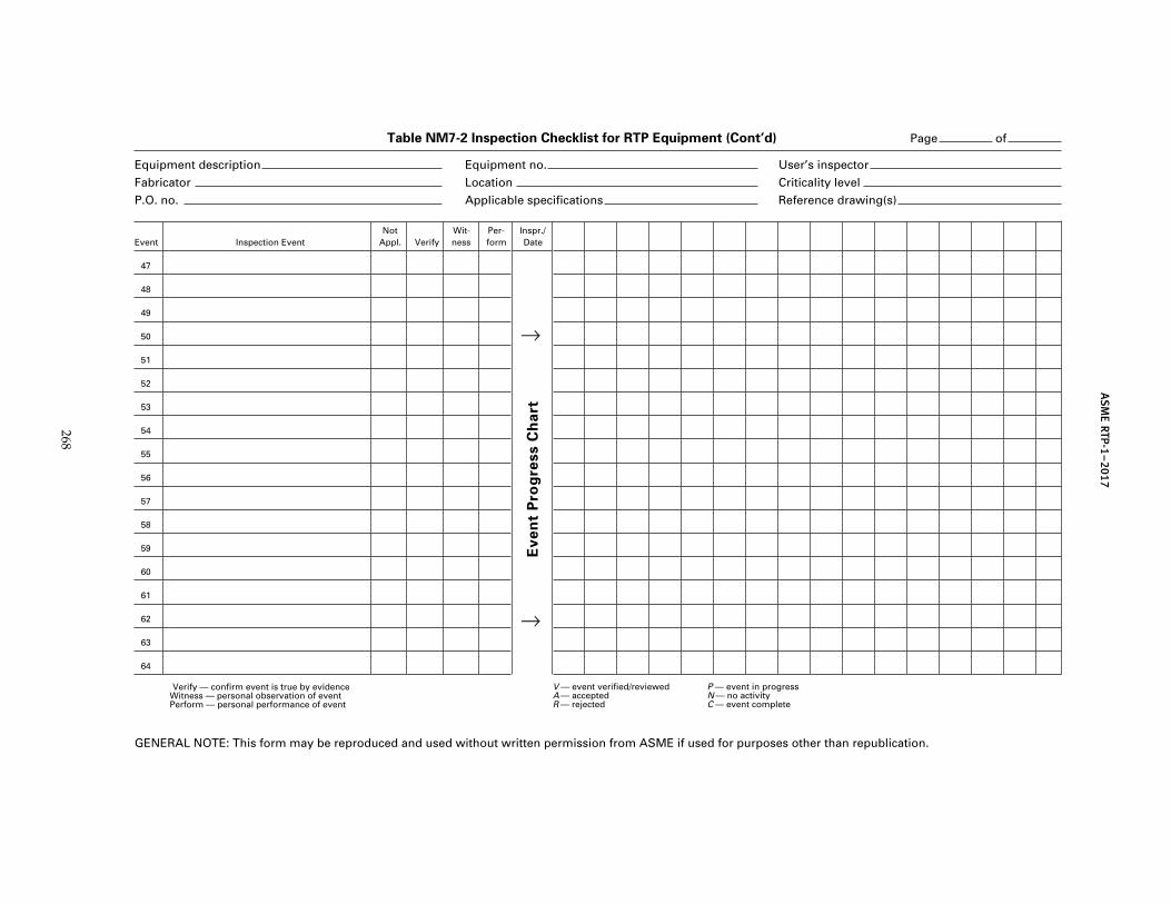
AS
ME
RTP-1–2017
Table NM7-2 Inspection Checklist for RTP Equipment (Cont’d) Page of
Equipment description Equipment no. User’s inspector
Fabricator Location Criticality level
P.O. no. Applicable specifications Reference drawing(s)
Event Inspection EventNot
Appl. VerifyWit-ness
Per-form
Inspr./Date
47
48
49
50
51
52
53
54
55
56
57
58
59
60
61
62
63
64
Verify — confirm event is true by evidenceWitness — personal observation of eventPerform — personal performance of event
V — event verified/reviewedA — acceptedR — rejected
P — event in progressN — no activityC — event complete
GENERAL NOTE: This form may be reproduced and used without written permission from ASME if used for purposes other than republication.
Ev
en
t P
rog
ress C
ha
rt
268
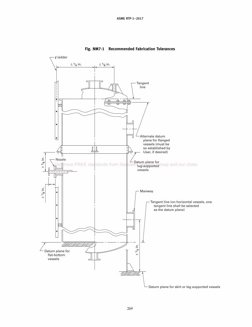
ASME RTP-1–2017
Fig. NM7-1 Recommended Fabrication Tolerances
Tangentline
ladder
Alternate datumplane for flangedvessels (must beso established byUser, if desired)
Datum plane forlug-supportedvessels
Manway
Tangent line (on horizontal vessels, onetangent line shall be selectedas the datum plane)
Datum plane for skirt or leg supported vessels
Datum plane forflat-bottomvessels
Nozzle
± 1 /
8 in
.±
1 /8
in.
± 1 /
4 in
.
± 1/4 in. ± 1/8 in.
c
269
Get more FREE standards from Standard Sharing Group and our chats

ASME RTP-1–2017
Fig. NM7-1 Recommended Fabrication Tolerances (Cont’d)
Bolt holes to straddle naturalcenterlines to within 1/16 in.,measured across the bolt holes(typical for all nozzles)
GENERAL NOTES:(a) The dimensional tolerance from the datum plane to any point on equipment (i.e., nozzle cen- terline) or other component shall be ± 1/8 in.(b) The orientation of flange faces, measured from outside edge to outside edge across the face, shall not deviate from the established planes of orientation by more than the following toler- ances:
(c) The following are special tolerances:
Nominal Nozzle Size Tolerance
6 in. and less 1/16 in.8 in. to 16 in. 3/32 in.18 in. and over 1/8 in.Manway 1/4 in.
Orientation: all nozzles and lugs shall beheld from reference points ± 1/8 in.
± 1/8 in. ± 1/8 in.
± 1/8 in.
± 1 /
8 in
.
± 1/8
in.
± 1/8 in.
ladderc
Description Tolerance
Face of nozzle to vessel sidewallFace of manway to vessel
sidewallFace of head-mounted nozzles to
datum plane:(1) Distances up to 60 in.(2) Distances over 60 in.
Face of manway to vessel head
± 1/8 in.± 1/4 in.
± 3/8 in.± 1/4 in.
± 1/4 in.
270

ASME RTP-1–2017
NONMANDATORY APPENDIX NM-8HANDLING AND SHIPPING
NM8-100 GENERAL
The techniques and procedures used for handling andpreparing RTP vessels for shipping should ensure deliv-ery of damage-free products.
The flexural, impact, and shear properties of RTP lami-nated structures are significantly lower than those ofmetallic structures. Therefore, special considerationmust be given to weight and weight distribution at con-tact points during handling, shipping, and storage ofRTP vessels.
If any doubt exists regarding the handling procedures,the Fabricator should be consulted.
NM8-200 HANDLING
(a) Impact or excessive distortion can cause crackingor crazing of the laminate structure. Therefore, specialconsideration must be given to the following:
(1) It is recommended that RTP vessels be lifted formoving or repositioning and not be rolled, slid, dropped,or thrown.
(2) Where lifting lugs are not provided as part ofthe equipment, consideration should be given to the useof woven fabric rigger-slings of 3-in. minimum widthfor lifting cylindrical vessels in a horizontal position.
(3) Open-end equipment, such as open-top tanks,may require internal cross bracing or external structureto prevent damage from distortion during handling andtransporting.
(4) For lifting an uncrated and unskidded open-end vessel in a vertical position, a spreader bar shouldbe used to prevent damage from excessive distortion(see Fig. NM8-1).
(b) Where a spreader bar is required for proper lifting,a stenciled notation to that effect should be applied tothe equipment in a prominent location prior to shipping.Woven fabric rigger-slings of 3-in. minimum width andadequate strength should be used in direct contact forlifting RTP vessels.
(c) Where a vessel is to be lifted in a horizontal posi-tion by wrapping a cable around its circumference,wooden strongbacks of adequate strength and dimen-sions should be employed to distribute the load andprevent direct contact between the cable and the wallof the equipment (see Fig. NM8-2).
(1) Generally, where the L/D value is high and/orthe laminate wall is thin, lifting attachments may be
271
Fig. NM8-1 Lifting Vessel With Spreader Bar
Vessel
Spreader bar
Fig. NM8-2 Strongback for Lifting
Get more FREE standards from Standard Sharing Group and our chats

ASME RTP-1–2017
required at two points, each located L/4 from an end(see Fig. NM8-3).
(2) Where an unusually long or bulky vessel isinvolved, special handling procedures may be requiredto avoid damage.
(3) Lifting cables and/or straps must not beattached to or permitted to come in contact with nozzles,flanges, gussets, or accessories other than lifting lugs,unless specifically approved by the Fabricator.
(4) When a vessel is being lifted using a cable, aguideline should be attached to prevent impact damagecaused by swing contact with other objects.
NM8-300 TEMPORARY STORAGE
During storage or repositioning, RTP vessels shouldbe left or placed on the shipping cradle or dunnageresting only on firm, level surfaces.
Vessels should not be permitted to rest on stones,tools, chocks, or other small hard objects.
When stored outdoors, vessels should be adequatelytied down to prevent movement due to wind or waterflotation. Closed vessels should not be completelysealed.
Where a large open-end vessel is stored in a horizontalposition, bracing is required at the open end to preventexcessive distortion. One cross brace, with suitable pad-ded end plates to distribute the load, should be installedperpendicular to the surface on which the vessel isresting.
NM8-400 SHIPPING
(a) Cylindrical vessels that are being shipped in ahorizontal position should be
(1) mounted on padded cradles of 120-deg mini-mum arc and as wide in inches as the vessel measuresin feet of diameter. The cradles should be placed as closeas possible to the top and bottom heads of the vesseland/or other stiffened areas.
(2) secured to the truck or railroad car with paddedbanding straps that are properly fastened to the bed ofthe vehicle.
(3) blocked at the ends to prevent shifting in transit.The blocks should be padded and bear only on theknuckle radius of the flat or dished heads.
(b) Vessels being shipped in a vertical position shouldbe secured to a pallet or skid, and then fastened tothe bed of the vehicle with padded banding for safeshipment.
(c) Vessels should be secured on the vehicle with11⁄2 in. or more clearance between the vessel (includingexternal fittings, nozzles, or other projections) and thebed of the truck or railcar. Small vessels may be shippedon pallets or skids to permit forklift truck handling.
272
Fig. NM8-3 Use of Strongbacks
Choker
Hook #2
Hook #1
Choker
1/4
1/4
(d) When two or more separate units are shippedtogether, sufficient clearance should be providedbetween units to prevent contact in transit.
(e) Flange faces 48 in. and under should be protectedby fully covering the flange and opening with suitableplywood or waterproof hardboard, securely fastened.In sizes larger than 48 in., only the flange faces need tobe covered.
(f) Pipe ends and nozzles should be protected by plas-tic caps, plywood, hardboard, or water-resistant card-board covering, securely fastened.
(g) All internals should be adequately secured and/orpadded to ensure safe shipment.
(h) Accessory pipe, fittings, and miscellaneous smallparts should be crated or boxed. Additional protectionwithin the crate or box may be required to ensure thatpieces are not damaged. Such protection may includecross bracing, end wrapping, and/or batten padding.Boxes are to be identified as to contents and purchaseorder number, or as otherwise required by the User.
(i) Crates or boxes exceeding 50-lb gross weightshould be mounted on skids or pallets to permit han-dling by crane or forklift truck.
(j) Crates or boxes should be secured to the vehicle.All crates, boxes, skids, and pallets should be made ofquality lumber and selected fasteners (nails, bolts, lagscrews, etc.) that will be sufficient to ensure safe han-dling and transit of the vessel.

(17)
ASME RTP-1–2017
NONMANDATORY APPENDIX NM-9INSTALLATION OF RTP VESSELS
NM9-100 SCOPE
This Appendix provides information pertaining to theinstallation of RTP vessels.
NM9-200 RECEIVING INSPECTION
Prior to removal from the truck, trailer, railcar, or ship-ping container, the vessel should be inspected to deter-mine if damage has been incurred during transit. Wheredamage is observed, the carrier’s representative shouldbe notified immediately. The unloading operationshould be delayed until the carrier’s representative hascompleted his or her inspection of the damaged vessel;otherwise, a damage claim may not be honored. Theinspection should include a complete check for
(a) external surface damage such as cuts, penetra-tions, delaminations, or fractured areas
(b) nozzle damage such as broken nozzles or flanges,or gouged flange faces
(c) internal surface damage such as crazing (whiteareas with star-shaped surface cracks)
(d) vessel damage at contact points of dunnage, cra-dles, chocks, or hold-down strap bands
NM9-300 INSTALLATION OF RTP VESSELS
(a) During storage or repositioning, RTP vesselsshould be placed only on firm level surfaces that arefree of stones, tools, and other small hard objects, sincecontact with such objects can cause localized damage.
(b) The support base surface should be nonporousand free of cracks, depressions, and vertical projections.Reinforced concrete with a smooth troweled finish isoften used as a support base. The support base shouldbe flat to within 1⁄4 in. of a horizontal plane. Local irregu-larities should not exceed 1⁄4 in. Sloping bases shall beequally flat.
(c) Each flat-bottom vessel should be set on a cushion-ing pad to minimize stress caused by seams, shrinkagedistortion, and/or support base or vessel bottom irregu-larities. This pad should be 1⁄2 in. thick, closed cell elasto-meric sponge material of suitable composition andcompression deflection range of 5 psi to 9 psi, resin orcement grout, petroleum-base mastic/sand mortar, orother suitable conforming material that will cushion thevessel bottom over surface irregularities of the supportbase or vessel bottom.
273
Fig. NM9-1 Flat-Face Valve Flange toFlat-Face RTP Nozzle Flange and Full-Face Gasket
Valve Vessel nozzle
Washer
Seal gasket
(d) Where a vessel has a bottom drain, provisionsshould be made in the support base with clearances sothat contact will not occur between the support baseand nozzles or nozzle flanges.
(e) Where a trench in a support base is required toaccommodate bottom discharge piping, a structuraltrench cover should be installed flush with the top ofthe support base to minimize the unsupported area ofthe vessel bottom.
(f) All flat-bottom vessels should be secured in placeby bolting to the support base through hold-down lugs.This precaution will minimize the chance of vessel dam-age at nozzle locations and areas of other attachmentdue to movement of the unit.
(g) Vessel nozzles should be joined to piping througha flexible connection or flexible piping system.
(h) Valves that are attached to vessel nozzles shouldbe independently supported so that the weight of thevalve or the force of closing and opening of a valve doesnot transmit the torque load directly to the nozzle.
(i) Flanged connections should be made in accor-dance with the Fabricator’s recommendations. Wherethe Fabricator’s recommendations are not available andwhere a flanged pipe or fitting is attached to a vesselnozzle with a full-face flange, the following apply:
(1) Full-face gaskets are to be used, per Fig. NM9-1.If the mating flange has a raised face, it should bemachined flat or a filler ring of the proper thicknessshould be applied to provide a full flat surface forcontact, per Fig. NM9-2. Gasket material with hardnessexceeding 65 durometer (Shore A) are notrecommended.
(2) Metal washers should be used under all boltheads and nuts that would otherwise be in contact withthe RTP flanges.
(3) All flanges should be back spot faced.
Get more FREE standards from Standard Sharing Group and our chats
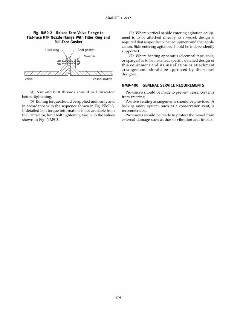
ASME RTP-1–2017
Fig. NM9-2 Raised-Face Valve Flange toFlat-Face RTP Nozzle Flange With Filler Ring and
Full-Face Gasket
Valve Vessel nozzle
Washer
Seal gasketFiller ring
(4) Nut and bolt threads should be lubricatedbefore tightening.
(5) Bolting torque should be applied uniformly andin accordance with the sequence shown in Fig. NM9-3.If detailed bolt torque information is not available fromthe Fabricator, limit bolt tightening torque to the valuesshown in Fig. NM9-3.
274
(6) Where vertical or side entering agitation equip-ment is to be attached directly to a vessel, design isrequired that is specific to that equipment and that appli-cation. Side entering agitators should be independentlysupported.
(7) Where heating apparatus (electrical tape, coils,or sparger) is to be installed, specific detailed design ofthis equipment and its installation or attachmentarrangements should be approved by the vesseldesigner.
NM9-400 GENERAL SERVICE REQUIREMENTS
Provisions should be made to prevent vessel contentsfrom freezing.
Positive venting arrangements should be provided. Abackup safety system, such as a conservation vent, isrecommended.
Provisions should be made to protect the vessel fromexternal damage such as due to vibration and impact.
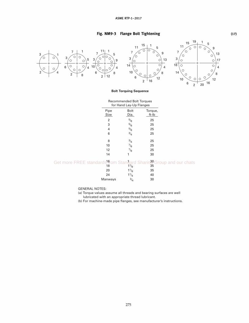
ASME RTP-1–2017
Fig. NM9-3 Flange Bolt Tightening
11
111
5
5
5 13
4444 88
8
22
22
16
Bolt Torquing Sequence
Recommended Bolt Torques for Hand Lay-Up Flanges
GENERAL NOTES:(a) Torque values assume all threads and bearing surfaces are well lubricated with an appropriate thread lubricant.(b) For machine-made pipe flanges, see manufacturer’s instructions.
PipeSize
BoltDia.
Torque,ft-lb
2 5/8 253 5/8 254 5/8 256 3/4 25
8 3/4 2510 7/8 2512 7/8 2514 1 30
16 1 3018 11/8 3520 11/8 3524 11/4 40
Manways 3/4 30
66
6
10
10 14
3333
77711
11
15
1212
9
9
59
13
17
4
8
12162026
10
14
18
3
7
1115 19
275
(17)
Get more FREE standards from Standard Sharing Group and our chats

ASME RTP-1–2017
NONMANDATORY APPENDIX NM-10REQUIREMENTS AND RESPONSIBILITIES OF USER (OR USER’SAGENT), FABRICATOR, INSPECTOR, AND CERTIFIED INDIVIDUAL
NM10-100 SCOPE AND PURPOSE
(a) The purpose of this Appendix is to provide a con-venient reference to the major responsibilities andrequirements as defined by this Standard for Users,Fabricators, Inspectors, and Certified Individuals. SeeFig. NM10-1 for an RTP-1 flowchart.
(b) Whereas a summary statement of each require-ment or responsibility is provided, the full text of eachreferenced paragraph provides details that are essentialto proper understanding.
(c) Any omissions (possibly due to revisions,addenda, oversight, etc.) do not relieve any party fromfull responsibility for compliance with all requirementscontained in the text of the Standard and addenda.
NM10-200 USER (OR USER’S AGENT)
The User (or User’s Agent) is the organization for whichthe equipment is being fabricated.
Requirements and ResponsibilitiesParagraph (A Summary Statement)
1-200 Provide UBRS (Table 1-1). Must specify theresin to be used or thoroughly define thechemical environment of the vessel.
1-210 Specify if the service is critical.1-220 Specify whether AE testing or postcuring is
required. Consider and define special safe-guards for the installation and operationof critical service vessels.
1-400 With the Fabricator, select the Inspectorprior to start of fabrication.
2-310 Specify the resin, the use of thixotropicagents, and/or fire-retardant synergists.
2A-224 Specify use of exterior veil, ultraviolet pro-tection, or pigmentation, if required.
3-100 If desired, specify option of design method-ology (Subpart 3A, Subpart 3B, or both).
3A-600 Select attachment materials.5-200 Specify and install overpressure protection
device(s).6-100 Specify inspections beyond those required
by this Standard.6-940(d) When exterior pigmentation or insulation is
specified, agree on visual inspection meth-ods and arrange for a proper schedule.
6-950(c) Prior to the start of fabrication, establish thepressure to be used if a vacuum test isrequired.
276
NM3-100 Specify the code to be used for seismic,wind, and snow loads.
NM7-100 Establish the acceptance criteria for inspec-tion to any special User requirements.
NM7-400(d) Reference dimensional tolerance fromFig. NM7-4 in the purchase contract orUBRS if these tolerances are to govern thefabrication.
NM7-500 Consult with the Fabricator about quantitylimitations on gaseous bubbles or blistersand agree on any limitations to beincluded in the purchase specifications.
App. NM-9 Ensure that the shipping, rigging, storing,and installation instructions are followed.
NM10-300 FABRICATOR
The Fabricator is the producer of RTP equipment. TheFabricator combines resin and reinforcing fibers to pro-duce the final product.
Requirements and ResponsibilitiesParagraph (A Summary Statement)
1-300 Prepare the Fabricator’s Design Report cer-tified by a Professional Engineer.
1-440 Provide plant access for the Inspector.Coordinate fabrication progress andinspection schedules with the Inspector.
1-520 Complete certification of compliance tothe Standard. Complete Fabricator’sData Report.
Subparts 2A–2C Develop design basis laminates.6-300(a)–(h) Prepare a written Quality Control Manual.
Provide all documents to the Inspectoras required. Assist the Inspector by pro-viding all necessary tools, test equip-ment, manpower, etc.
6-400 Ensure that the vessel is in proper entrycondition for inspection.
6-900(a), (c) Provide final inspection documents to theInspector.
6-910(a), (c) Make all necessary checks to ensureproper resin cure.
6-920(a) Verify dimensions and laminate thickness.6-930(a), (b), (d) Ensure laminate mechanical properties
and laminate reinforcement content andsequence are in accordance with design.Proof test laminates when required bypara. 6-930(d) (based on designpressure).

ASME RTP-1–2017
6-940 Make all checks necessary to ensure thatlaminate imperfections are within therequirements of this Standard.
6-950(a)–(e) Perform pressure tests.7-100 Meet all requirements as outlined in this
Standard for shop qualification.App. M-1, Perform inspection and test for reinforce-
Articles A–D ment materials received.App. M-2, Perform inspection and tests on resins and
Articles A–E curing agents.App. M-2, Perform inspection on common additives.
Article GM4-100 Prepare and maintain a Quality Control
Program.M5-200 Train and qualify Laminators and
Secondary Bonders.M6-100 Design, fabricate, and test a demonstration
vessel.App. M-7 Develop repair procedures in accordance
with requirements in that MandatoryAppendix. Correct all nonconformitiesin vessels.
NM7-300 Comply with all special purchase orderrequirements, specifications, instruc-tions, or drawings.
NM10-400 INSPECTORInspector (with uppercase “I”) is defined in para. 1-400.
Requirements and ResponsibilitiesParagraph (A Summary Statement)
1-430 Verify that requirements of this Standard havebeen met and that design has beenreviewed and certified by a ProfessionalEngineer. Perform all specific inspections asrequired by this Standard.
1-440 Make arrangements with the Fabricator fortimely inspections.
1-520(c) Sign Fabricator’s Design Report (or PartialData Report).
6-300(b), (e) Inspect any subassemblies or components fab-ricated by a Subcontractor of the Fabricator.Verify that the Fabricator’s Quality ControlProgram is in effective operation. Makesuch specific inspections and tests as arerequired by this Standard; provide a com-plete report including all data as requiredin paras. 6-910 through 6-960.
6-300(i) Sign the Certificate of Inspection on theFabricator’s Data Report.
6-500 Examine Fabricator’s design record andreport. Verify that the vessel conforms tothe latest revision of approved drawingsand the UBRS. Verify that the Fabricator’sDesign Report has been certified by a regis-tered Professional Engineer.
6-600 Verify that the materials used in fabricationcomply with the requirements of thisStandard and the UBRS.
6-700 Establish hold points and verify fabrication.At completion of each hold point, Inspectorshall report results and highlight any dis-crepancies requiring corrective action.
6-900(a) Review the final revision of documents at thetime of final inspection.
277
6-900(d) Summarize inspection in a brief report andsubmit the report to the Fabricator.
6-900(e) Sign and date the Certificate of Compliance.6-910(b), (d) Verify proper use, formulation, and cure of
resin (hardness and acetone).6-920 Verify thickness and dimensional data.6-930 Verify reinforcing sequence either by visual or
by burnout tests as required. Verify that aregistered Professional Engineer hasreviewed the Proof Test data.
6-940 Ascertain the proper Visual Inspection Levelof the laminate and conduct the visualinspection.
7-500(c) Verify that the Fabricator’s record keeping sys-tem satisfies the requirements of thisStandard.
M5-300(e) Require requalification of Laminator(s) if abil-ity becomes questionable.
M5-450(c) Require requalification of SecondaryBonder(s) if ability becomes questionable.
M7-210(c) Review and approve all repair procedures inadvance.
M7-210(f) Reinspect all repairs to ensure compliancewith this Standard.
M8-200(c) Witness acoustic emission test (if required)and verify the acoustic emission examina-tion report.
NM10-500 CERTIFIED INDIVIDUAL
Certified Individual (CI) is defined in para. 1-400.
Requirements and ResponsibilitiesParagraph (A Summary Statement)
1-400 Protect the ASME mark by carrying out theduties described in this Standard.
1-410(a) Perform an annual audit to verify that theFabricator’s Quality Assurance System iscurrent and in effective operation.
1-410(b) Verify that the qualifications of the Inspectorand inspector are in accordance with theFabricator’s Quality Assurance System.
1-410(c) Verify that corrective actions resulting fromASME audits are properly resolved.
1-410(d) Verify that corrective actions taken to resolvevessel nonconformities are in accordancewith the Fabricator’s Quality AssuranceProgram.
1-410(e) Verify that the responsibilities and activitiesof the Inspector are in accordance with therequirements of the Standard.
1-410(f) Verify that vessels are manufactured by quali-fied Laminators and Secondary Bonders.
1-410(g) Sign the Fabricator’s Partial Data Report sub-sequent to completion of all inspections bythe Inspector, in the case that only compo-nents are being produced.
1-410(h) Approve the application of the ASME markby signing the Fabricator’s Certificate ofCompliance on the Fabricator’s Data Reportsubsequent to completion of all inspectionsby the Inspector.
Get more FREE standards from Standard Sharing Group and our chats

ASME RTP-1–2017
1-420(a) Have a minimum of a high-school diplomaand 5-yr experience in the RTP corrosionresistance industry.
1-420(b) Demonstrate inspection ability to theFabricator employing him/her.
1-420(c) Have satisfactory expertise and experienceaccording to the complexity of theassignment.
1-420(d) Have knowledge of ASME RTP-1.1-420(e) Have knowledge of the Fabricator’s Quality
Assurance Program and shop procedure.1-420(f) Have the knowledge and ability to evaluate
and monitor procedures and performance.1-420(g) Have knowledge of keeping and maintaining
records.
278
1-520(b) Complete and sign the Fabricator’s DataReport or Fabricator’s Partial Data Report,as applicable.
6-300(i) Sign the Inspector’s Certification on theFabricator’s Data Report when he/she is sat-isfied that all requirements of the Standardhave been met.
M5-300(e) Require requalification of a Laminator if his/her ability becomes questionable.
M5-450(c) Require requalification of a Secondary Bonderif his/her ability becomes questionable.
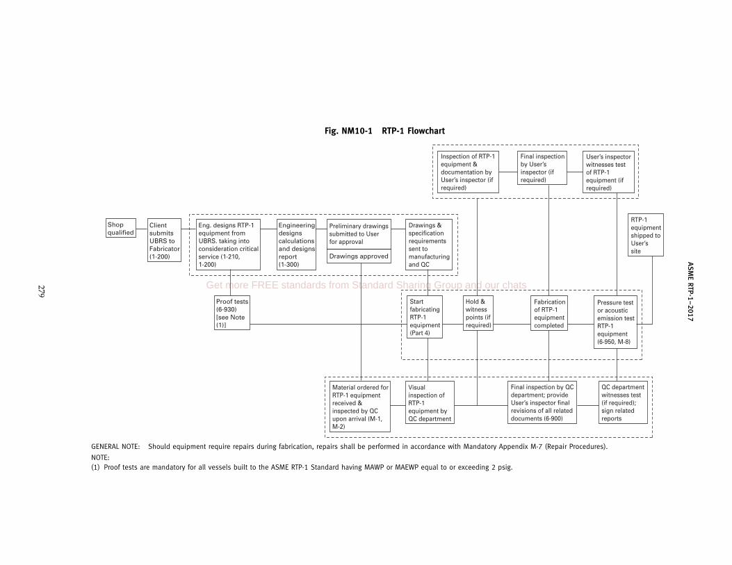
AS
ME
RTP-1–2017
Fig. NM10-1 RTP-1 Flowchart
Engineering designs calculations and designs report (1-300)
Drawings & specification requirements sent to manufacturing and QC
Inspection of RTP-1 equipment & documentation by User’s inspector (if required)
Final inspection by User’s inspector (if required)
RTP-1 equipment shipped to User’s site
Pressure test or acoustic emission test RTP-1 equipment (6-950, M-8)
Fabrication of RTP-1 equipment completed
Hold & witness points (if required)
Start fabricating RTP-1 equipment (Part 4)
Material ordered for RTP-1 equipment received & inspected by QC upon arrival (M-1, M-2)
Visual inspection of RTP-1 equipment by QC department
Final inspection by QC department; provide User’s inspector final revisions of all related documents (6-900)
QC department witnesses test (if required); sign related reports
User’s inspector witnesses test of RTP-1 equipment (if required)
Proof tests (6-930) [see Note (1)]
Eng. designs RTP-1 equipment from UBRS. taking into consideration critical service (1-210, 1-200)
Client submits UBRS to Fabricator (1-200)
Shop qualified
Drawings approved
Preliminary drawings submitted to User for approval
GENERAL NOTE: Should equipment require repairs during fabrication, repairs shall be performed in accordance with Mandatory Appendix M-7 (Repair Procedures).
NOTE:(1) Proof tests are mandatory for all vessels built to the ASME RTP-1 Standard having MAWP or MAEWP equal to or exceeding 2 psig.
279
Get more FREE standards from Standard Sharing Group and our chats

ASME RTP-1–2017
NONMANDATORY APPENDIX NM-11DESIGN FOR 250-lb CONCENTRATED LOAD ON A
TORISPHERICAL HEAD
NM11-100 SCOPE
This Appendix provides a procedure for calculatingthe thickness of a torispherical top head that satisfiespara. 3A-340. The procedure is limited to heads thatsatisfy para. 3A-230, and whose inside diameter is notmore than 144 in. The inside diameter of a torisphericalhead is defined as the inside diameter of the cylindricalshell to which it is attached.
NM11-200 NOMENCLATURE
The following symbols are used in the equations forcalculating the stress in the head:
F p design factorG p stress function, lbP p design pressure, psi (the sign of P is positive
if the design pressure is internal and negativeif the design pressure is external)
R p inside radius of the crown of the head, in.Su p ultimate tensile strength of the laminate, psiS1 p stress on the upper surface of the head, psiS2 p stress on the lower surface of the head, psi
t p thickness of the crown, in.
NM11-300 DESIGN FACTOR
If the 250 lb load is intermittent and temporary, thedesign factor Fp5; otherwise, Fp10.
280
NM11-400 STRESS CALCULATIONS
(a) Upper Surface. The stress on the upper surface ofthe head is checked as follows:
(1) Calculate (Rt)0.5.(2) Enter Fig. NM11-1 with the value from (a)(1)
and obtain a value for G from the curve for the uppersurface. The negative sign denotes that the stress is com-pressive.
(3) Calculate the stress S1 p G/t2.(4) The absolute value of S1 must be less than or
equal to Su/F.(5) If the design pressure is external, the absolute
value of the quantity S1 + PR/t must also be less thanor equal to Su/F.
(6) If either of the conditions in (a)(4) or (a)(5) isviolated, increase t and repeat (a)(1) through (a)(5).
(b) Lower Surface. The stress on the lower surface maybe checked as follows:
(1) Enter Fig. NM11-1 with the value of (Rt)0.5 from(a)(1), and obtain a value for G from the curve for thelower surface.
(2) Calculate the stress S2 p G/t2.(3) S2 must be less than or equal to Su/F.(4) If the design pressure is internal, the quantity
S2 + PR/t must also be less than or equal to Su/F.(5) If either of the conditions in (b)(3) or (b)(4) is
violated, increase t and repeat (b)(1) through (b)(4).

ASME RTP-1–2017
Fig. NM11-1 Stress Function
400
0 2 4 6 8 10 12
Rt
14 16 18 20
300
200
100
0G
−100
−200
−300
−400
Lower surface
Upper surface
281
Get more FREE standards from Standard Sharing Group and our chats
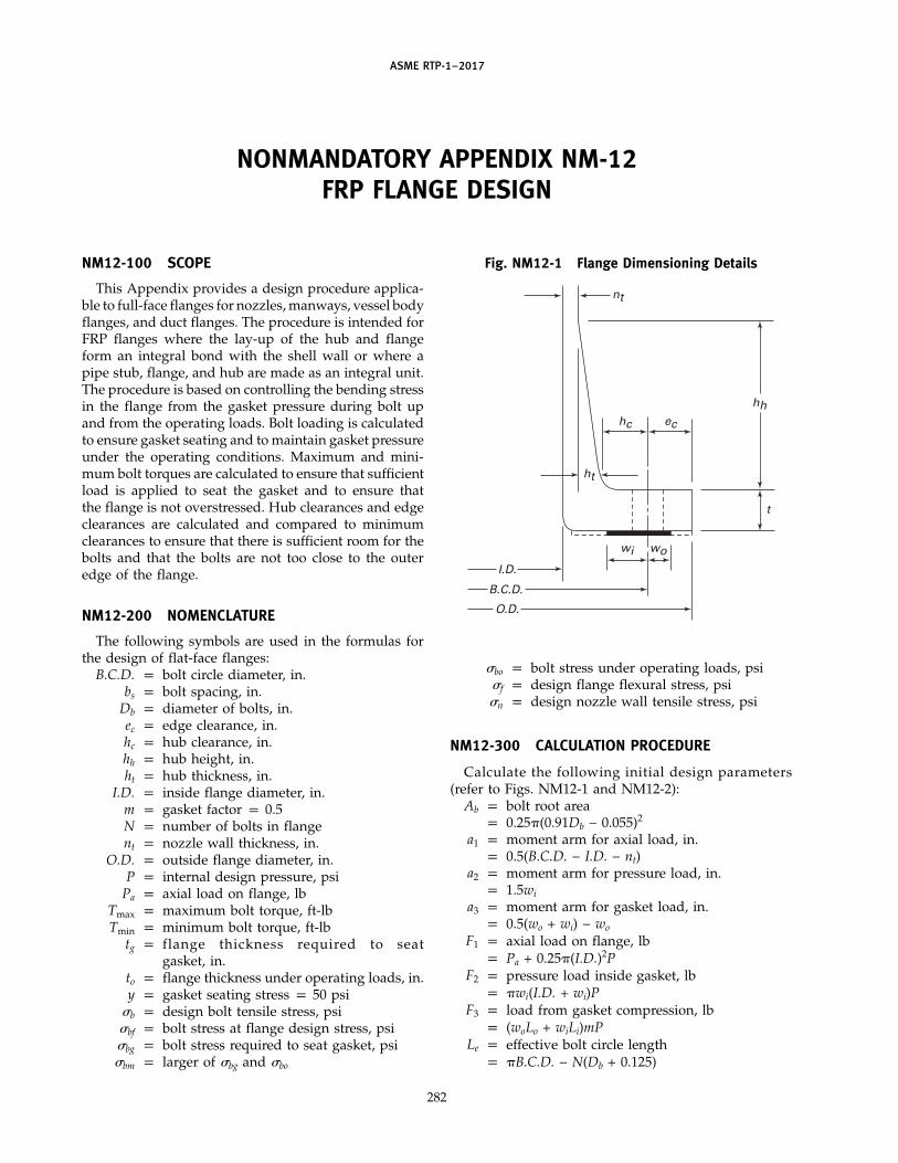
ASME RTP-1–2017
NONMANDATORY APPENDIX NM-12FRP FLANGE DESIGN
NM12-100 SCOPE
This Appendix provides a design procedure applica-ble to full-face flanges for nozzles, manways, vessel bodyflanges, and duct flanges. The procedure is intended forFRP flanges where the lay-up of the hub and flangeform an integral bond with the shell wall or where apipe stub, flange, and hub are made as an integral unit.The procedure is based on controlling the bending stressin the flange from the gasket pressure during bolt upand from the operating loads. Bolt loading is calculatedto ensure gasket seating and to maintain gasket pressureunder the operating conditions. Maximum and mini-mum bolt torques are calculated to ensure that sufficientload is applied to seat the gasket and to ensure thatthe flange is not overstressed. Hub clearances and edgeclearances are calculated and compared to minimumclearances to ensure that there is sufficient room for thebolts and that the bolts are not too close to the outeredge of the flange.
NM12-200 NOMENCLATURE
The following symbols are used in the formulas forthe design of flat-face flanges:
B.C.D. p bolt circle diameter, in.bs p bolt spacing, in.
Db p diameter of bolts, in.ec p edge clearance, in.hc p hub clearance, in.hh p hub height, in.ht p hub thickness, in.
I.D. p inside flange diameter, in.m p gasket factor p 0.5N p number of bolts in flangent p nozzle wall thickness, in.
O.D. p outside flange diameter, in.P p internal design pressure, psi
Pa p axial load on flange, lbTmax p maximum bolt torque, ft-lbTmin p minimum bolt torque, ft-lb
tg p flange thickness required to seatgasket, in.
to p flange thickness under operating loads, in.y p gasket seating stress p 50 psi
�b p design bolt tensile stress, psi�bf p bolt stress at flange design stress, psi�bg p bolt stress required to seat gasket, psi�bm p larger of �bg and �bo
282
Fig. NM12-1 Flange Dimensioning Details
hh
I.D.
B.C.D.
O.D.
nt
ht
hc
wi wo
ec
t
�bo p bolt stress under operating loads, psi�f p design flange flexural stress, psi�n p design nozzle wall tensile stress, psi
NM12-300 CALCULATION PROCEDURE
Calculate the following initial design parameters(refer to Figs. NM12-1 and NM12-2):
Ab p bolt root areap 0.25�(0.91Db − 0.055)2
a1 p moment arm for axial load, in.p 0.5(B.C.D. − I.D. − nt)
a2 p moment arm for pressure load, in.p 1.5wi
a3 p moment arm for gasket load, in.p 0.5(wo + wi) − wo
F1 p axial load on flange, lbp Pa + 0.25�(I.D.)2P
F2 p pressure load inside gasket, lbp �wi(I.D. + wi)P
F3 p load from gasket compression, lbp (woLo + wiLi)mP
Le p effective bolt circle lengthp �B.C.D. − N(Db + 0.125)

ASME RTP-1–2017
Fig. NM12-2 Flange Loading Conditions
a1
a2
a3
F1 + F2 + F3
F1
F2 F3
(a) Operating Loads
Bolt loading
(wiLi + woLo)y
(b) Gasket Seating Load
Bolt loading
Gasket seating pressure y
Li p length of inside effective gasketp �(B.C.D. − wi)
Lo p length of outside effective gasketp �(B.C.D. + wo)
wi p effective gasket width inside B.C.D.p 0.25(B.C.D. − I.D.)
wo p effective gasket width outside B.C.D.p 0.25(O.D. − B.C.D.)
NM12-310 Nozzle Wall Thickness
Calculate the nozzle wall thickness for internal pres-sure and for the axial load.
np p PI.D.2�n
na pPa
�I.D.�n
The required nozzle wall thickness, nt, is the larger ofnp and na.
NM12-320 Gasket Seating Loads
Calculate the bolt stress and flange thickness requiredto seat the gasket.
�bg p(woLo + wiLi)y
NAb
tg p 3yLe�f
(w2oLo + w2
i Li)
283
NM12-330 Design Operating Loads
Calculate the bolt stress and flange thickness requiredfor the operating conditions.
�bo pF1 + F2 + F3
NAb
to p 6(F1a1 + F2a2 + F3a3)Le�f
NM12-340 Flange Thickness
The required flange thickness, t, is then the greater oftg and to, and the bolt stresses must be less than thedesign bolt stress.
NM12-350 Minimum Bolt Torque
Using the larger of the two bolt stresses, calculate theminimum bolt torque (ft-lb) required.
�bm p larger of �bg and �bo
Tmin p�bmAbDb
60
NM12-360 Maximum Bolt Torque
Using the required flange thickness, calculate the max-imum bolt torque (ft-lb) that the flange can withstandand the maximum bolt torque the bolt can withstand.
�bf pLet
2�f(woLo + wiLi)
3NAb(w2oLo + w2
i Li)
Get more FREE standards from Standard Sharing Group and our chats
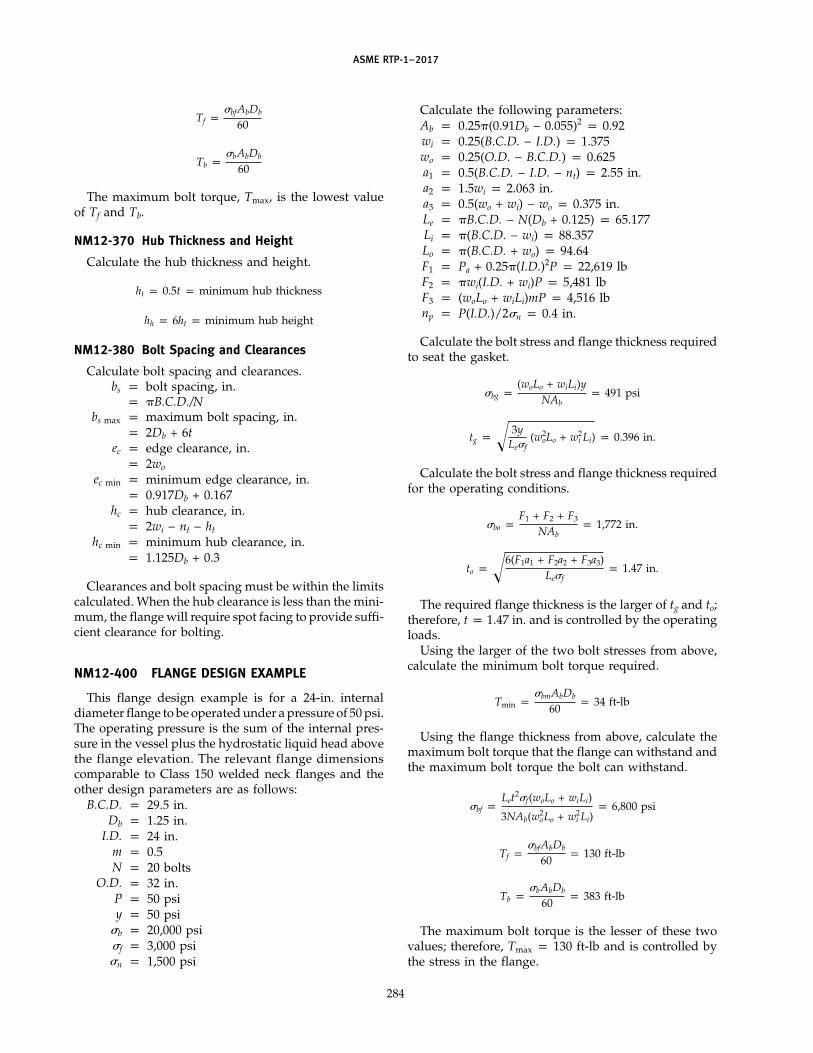
ASME RTP-1–2017
Tf p�bfAbDb
60
Tb p�bAbDb
60
The maximum bolt torque, Tmax, is the lowest valueof Tf and Tb.
NM12-370 Hub Thickness and Height
Calculate the hub thickness and height.
ht p 0.5t p minimum hub thickness
hh p 6ht p minimum hub height
NM12-380 Bolt Spacing and Clearances
Calculate bolt spacing and clearances.bs p bolt spacing, in.
p �B.C.D./Nbs max p maximum bolt spacing, in.
p 2Db + 6tec p edge clearance, in.
p 2wo
ec min p minimum edge clearance, in.p 0.917Db + 0.167
hc p hub clearance, in.p 2wi − nt − ht
hc min p minimum hub clearance, in.p 1.125Db + 0.3
Clearances and bolt spacing must be within the limitscalculated. When the hub clearance is less than the mini-mum, the flange will require spot facing to provide suffi-cient clearance for bolting.
NM12-400 FLANGE DESIGN EXAMPLE
This flange design example is for a 24-in. internaldiameter flange to be operated under a pressure of 50 psi.The operating pressure is the sum of the internal pres-sure in the vessel plus the hydrostatic liquid head abovethe flange elevation. The relevant flange dimensionscomparable to Class 150 welded neck flanges and theother design parameters are as follows:
B.C.D. p 29.5 in.Db p 1.25 in.
I.D. p 24 in.m p 0.5N p 20 bolts
O.D. p 32 in.P p 50 psiy p 50 psi
�b p 20,000 psi�f p 3,000 psi�n p 1,500 psi
284
Calculate the following parameters:Ab p 0.25�(0.91Db − 0.055)2 p 0.92wi p 0.25(B.C.D. − I.D.) p 1.375wo p 0.25(O.D. − B.C.D.) p 0.625a1 p 0.5(B.C.D. − I.D. − nt) p 2.55 in.a2 p 1.5wi p 2.063 in.a3 p 0.5(wo + wi) − wo p 0.375 in.Le p �B.C.D. − N(Db + 0.125) p 65.177Li p �(B.C.D. − wi) p 88.357Lo p �(B.C.D. + wo) p 94.64F1 p Pa + 0.25�(I.D.)2P p 22,619 lbF2 p �wi(I.D. + wi)P p 5,481 lbF3 p (woLo + wiLi)mP p 4,516 lbnp p P(I.D.)/2�n p 0.4 in.
Calculate the bolt stress and flange thickness requiredto seat the gasket.
�bg p(woLo + wiLi)y
NAbp 491 psi
tg p 3yLe�f
(w2oLo + w2
i Li) p 0.396 in.
Calculate the bolt stress and flange thickness requiredfor the operating conditions.
�bo pF1 + F2 + F3
NAbp 1,772 in.
to p 6(F1a1 + F2a2 + F3a3)Le�f
p 1.47 in.
The required flange thickness is the larger of tg and to;therefore, t p 1.47 in. and is controlled by the operatingloads.
Using the larger of the two bolt stresses from above,calculate the minimum bolt torque required.
Tmin p�bmAbDb
60p 34 ft-lb
Using the flange thickness from above, calculate themaximum bolt torque that the flange can withstand andthe maximum bolt torque the bolt can withstand.
�bf pLet
2�f(woLo + wiLi)
3NAb(w2oLo + w2
i Li)p 6,800 psi
Tf p�bfAbDb
60p 130 ft-lb
Tb p�bAbDb
60p 383 ft-lb
The maximum bolt torque is the lesser of these twovalues; therefore, Tmax p 130 ft-lb and is controlled bythe stress in the flange.

ASME RTP-1–2017
The hub thickness and height are
ht p 0.5t p 0.74 in.
hh p 6ht p 4.4 in.
Calculate clearances and bolt spacing.
hc p 2wi − nt − ht p 1.61 in.
hc min p 1.125Db + 0.3 p 1.70 in.
ec p 2wo p 1.25 in.
285
ec min p 0.917Db + 0.167 p 1.31 in.
bs p�B.C.D.
Np 4.63 in.
bs max p 2Db + 6t p 11.34 in.
In this case, the hub clearance and the edge clearanceare slightly less than the recommended minimum, butare considered adequate, and spot facing will berequired on the back face of the flange to provide washerclearance.
Get more FREE standards from Standard Sharing Group and our chats
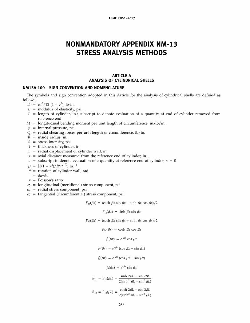
ASME RTP-1–2017
NONMANDATORY APPENDIX NM-13STRESS ANALYSIS METHODS
ARTICLE AANALYSIS OF CYLINDRICAL SHELLS
NM13A-100 SIGN CONVENTION AND NOMENCLATURE
The symbols and sign convention adopted in this Article for the analysis of cylindrical shells are defined asfollows:
D p Et3/12 (1 − �2), lb-in.E p modulus of elasticity, psiL p length of cylinder, in.; subscript to denote evaluation of a quantity at end of cylinder removed from
reference endM p longitudinal bending moment per unit length of circumference, in.-lb/in.p p internal pressure, psi
Q p radial shearing forces per unit length of circumference, lb/in.R p inside radius, in.S p stress intensity, psit p thickness of cylinder, in.
w p radial displacement of cylinder wall, in.x p axial distance measured from the reference end of cylinder, in.o p subscript to denote evaluation of a quantity at reference end of cylinder, x p 0� p �3(1 − �2)/R2t2� 1⁄4, in.−1
� p rotation of cylinder wall, radp dw/dx
� p Poisson’s ratio�l p longitudinal (meridional) stress component, psi�r p radial stress component, psi�t p tangential (circumferential) stress component, psi
F11(�x) p (cosh �x sin �x − sinh �x cos �x)/2
F12(�x) p sinh �x sin �x
F13(�x) p (cosh �x sin �x + sinh �x cos �x)/2
F14(�x) p cosh �x cos �x
f1(�x) p e−�x cos �x
f2(�x) p e−�x (cos �x − sin �x)
f3(�x) p e−�x (cos �x + sin �x)
f4(�x) p e−�x sin �x
B11 p B11(�L) psinh 2�L − sin 2�L
2(sinh2 �L − sin2 �L)
B12 p B12(�L) pcosh 2�L − cos 2�L
2(sinh2 �L − sin2 �L)
286

ASME RTP-1–2017
B22 p B22(�L) psinh 2�L + sin 2�L
sinh2 �L − sin2 �L
G11 p G11(�L) p −cosh �L sin �L − sinh �L cos �L
sinh2 �L − sin2 �L
G12 p G12(�L) p −2 sinh �L sin �L
sinh2 �L − sin2 �L
G22 p G22(�L) p −2(cosh �L sin �L + sinh �L cos �L)
sinh2 �L − sin2 �L
The sign convention arbitrarily chosen for the analysis of cylindrical shells in this Article is as indicated inFig. NM13A-1. Positive directions assumed for pertinent quantities are indicated.
NM13A-200 PRINCIPAL STRESSES AND STRESS INTENSITIES DUE TO INTERNAL PRESSURE
The formulas for principal stresses and stress intensities presented in this paragraph include the loading effectsof internal pressure only and exclude the effects of all structural discontinuities.
NM13A-210 Principal Stresses
The principal stresses developed at any point in the wall of a cylindrical shell due to internal pressure are givenby the following formulas:
�1 p �t p pR/t (1)
�2 p �l p pR/2t (2)
�3 p �r p 0 (3)
NM13A-220 Stress Intensities
The general primary membrane stress intensity developed across the thickness of a cylindrical shell due to internalpressure is given by the following formula:
S ppRt
NM13A-300 BENDING ANALYSIS FOR UNIFORMLY DISTRIBUTED EDGE LOADS
The formulas in this paragraph describe the behavior of a cylindrical shell when subjected to the action ofbending moments, M (in.-lb/in. of circumference), and radial shearing forces, Q (lb/in. of circumference), uniformlydistributed at the edges and acting at the mean radius of the shell. The behavior of the shell due to all other loadingsmust be evaluated independently and combined by superposition.
NM13A-310 Displacements, Bending Moments, and Shearing Forces in Terms of Conditions at Reference Edge,x p 0
(a) The radial displacement, w(x); angular displacement or rotation, �(x); bending moments, M(x); and radialshearing forces, Q(x), at any axial location of the cylinder are given by the following equations in terms of wo, �o,Mo, and Qo:
w(x) p (Qo/2�3D)F11(�x) + (Mo/2�2D)F12(�x) + (�o/�)F13(�x) + woF14(�x) (1)
�(x)/� p (Qo/2�3D)F12(�x) + 2(Mo/2�2D)F13(�x) + (�o/�)F14(�x) − 2woF11(�x) (2)
M(x)/2�2D p (Qo/2�3D)F13(�x) + (Mo/2�2D)F14(�x) − (�o/�)F11(�x) − woF12(�x) (3)
Q(x)/2�3D p (Qo/2�3D)F14(�x) − 2(Mo/2�2D)F11(�x) − (�o/�)F12(�x) − 2woF13(�x) (4)
287
Get more FREE standards from Standard Sharing Group and our chats
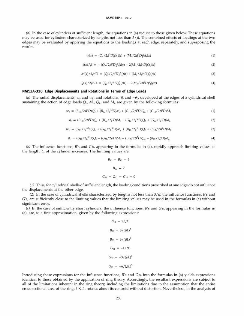
ASME RTP-1–2017
(b) In the case of cylinders of sufficient length, the equations in (a) reduce to those given below. These equationsmay be used for cylinders characterized by lengths not less than 3/�. The combined effects of loadings at the twoedges may be evaluated by applying the equations to the loadings at each edge, separately, and superposing theresults.
w(x) p (Qo/2�3D)f1(�x) + (Mo/2�2D)f2(�x) (1)
�(x)/� p − (Qo/2�3D)f3(�x) − 2(Mo/2�2D)f1(�x) (2)
M(x)/2�2D p (Qo/2�3D)f4(�x) + (Mo/2�2D)f3(�x) (3)
Q(x)/2�3D p (Qo/2�3D)f2(�x) − 2(Mo/2�2D)f4(�x) (4)
NM13A-320 Edge Displacements and Rotations in Terms of Edge Loads
(a) The radial displacements, wo and wL, and rotations, �o and −�L, developed at the edges of a cylindrical shellsustaining the action of edge loads Qo, Mo, QL, and ML are given by the following formulas:
wo p (B11/2�3D)Qo + (B12/2�2D)Mo + (G11/2�3D)QL + (G12/2�2D)ML (1)
−�o p (B12/2�2D)Qo + (B22/2�D)Mo + (G12/2�2D)QL + (G22/2�D)ML (2)
wL p (G11/2�3D)Qo + (G12/2�2D)Mo + (B11/2�3D)QL + (B12/2�2D)ML (3)
�L p (G12/2�2D)Qo + (G22/2�D)Mo + (B12/2�2D)QL + (B22/2�D)ML (4)
(b) The influence functions, B’s and G’s, appearing in the formulas in (a), rapidly approach limiting values asthe length, L, of the cylinder increases. The limiting values are
B11 p B12 p 1
B22 p 2
G11 p G12 p G22 p 0
(1) Thus, for cylindrical shells of sufficient length, the loading conditions prescribed at one edge do not influencethe displacements at the other edge.
(2) In the case of cylindrical shells characterized by lengths not less than 3/�, the influence functions, B’s andG’s, are sufficiently close to the limiting values that the limiting values may be used in the formulas in (a) withoutsignificant error.
(c) In the case of sufficiently short cylinders, the influence functions, B’s and G’s, appearing in the formulas in(a), are, to a first approximation, given by the following expressions:
B11 p 2/�L
B12 p 3/(�L)2
B22 p 6/(�L)3
G11 p −1/�L
G12 p −3/(�L)2
G22 p −6/(�L)3
Introducing these expressions for the influence functions, B’s and G’s, into the formulas in (a) yields expressionsidentical to those obtained by the application of ring theory. Accordingly, the resultant expressions are subject toall of the limitations inherent in the ring theory, including the limitations due to the assumption that the entirecross-sectional area of the ring, t � L, rotates about its centroid without distortion. Nevertheless, in the analysis of
288

ASME RTP-1–2017
very short cylindrical shells characterized by lengths not greater than 0.5/�, the expressions may be used withoutintroducing significant error.
NM13A-330 Principal Stresses Due to Bending
The principal stresses developed at the surfaces of a cylindrical shell at any axial location x due to uniformlydistributed edge loads (see Fig. NM13A-1) are given by the following formulas:
�1 p �t(x) pEw(x)
R + t/2±
6�M(x)
t2(1)
�2 p �l(x) p ±6M(x)/t2 (2)
�3 p �r p 0 (3)
In these formulas, where terms are preceded by a double sign ±, the upper sign refers to the inside surface of thecylinder and the lower sign refers to the outside surface.
ARTICLE BANALYSIS OF SPHERICAL SHELLS
NM13B-100 SCOPE
(a) In this Article, formulas are given for stresses and deformations in spherical shells subjected to internal orexternal pressure.
(b) Formulas are also given for bending analysis of partial spherical shells under the action of uniformly distributededge forces and moments.
NM13B-200 NOMENCLATURE AND SIGN CONVENTION
The symbols and sign convention adopted in this Article are defined as follows:D p flexural rigidity, in.-lb
p Et3/12(1 − �2)pE p modulus of elasticity, psi
H p force per unit length of circumference, perpendicular to centerline of sphere, lb/in.M p meridional bending moment per unit length of circumference, in.-lb/in.N p membrane force, lb/in.p p uniform pressure, internal or external, psi
Q p radial shearing force per unit of circumference, lb/in.R p inside radius, in.S p stress intensity, psit p thickness of spherical shell, in.
w p radial displacement of midsurface, in.x p length of arc for angle �, measured from reference edge of hemisphere
p R�, in.� p meridional angle measured from the reference edge, rad� p �3(1 − �2)/R2t2� 1⁄4, 1/in.
�o p tan−1 (−k1), rad� p lateral displacement of midsurface, perpendicular to centerline of spherical shell, in.� p rotation of midsurface, rad p �R� p Poisson’s ratio
�l p longitudinal (meridional) stress component, psi�r p radial stress component, psi�t p tangential (circumferential) stress component, psi p meridional angle measured from centerline of sphere, rad
L p meridional angle of second edge, rado p meridional angle of reference edge where loading is applied, rad
l p subscript to denote meridional direction
289
Get more FREE standards from Standard Sharing Group and our chats

ASME RTP-1–2017
o p subscript to denote a quantity at reference edge of spheret p subscript used to denote circumferential direction
K1 p 1 −1 − 2�
2cot (o − �)
K2 p 1 −1 + 2�
2cot (o − �)
k1 p 1 −1 − 2�
2cot o
k2 p 1 −1 + 2�
2cot o
Ao p �1 + k21
B(at �) p (1 + �2)(K1 + K2) − 2K2
C(at �) p �sin o/sin (o − �)
F(at �) p �sin (o) sin (o − �)
The sign convention is listed below and shown in Fig. NM13B-1 by the positive directions of the pertinentquantities.
(H), (Ho) p force perpendicular to centerline, positive outward(M), (Mo) p moment, positive when causing tension on the inside surface(Nt), (Nl) p membrane force, positive when causing tension
(p) p pressure, positive radially outward(�) p lateral displacement, perpendicular to centerline of sphere, positive outward(�) p rotation, positive when accompanied by an increase in the radius or curvature, as caused by a
positive moment
NM13B-300 PRINCIPAL STRESSES AND STRESS INTENSITIES RESULTING FROM INTERNAL OR EXTERNALPRESSURE
In this section, formulas are given for principal stresses and stress intensities resulting from uniformly distributedinternal or external pressure in complete or partial spherical shells. The effects of discontinuities in geometry andloading are not included and should be evaluated independently. The stresses resulting from all effects must becombined by superposition.
NM13B-310 Principal Stresses Resulting From Internal Pressure
The principal stresses at any point in the wall of a spherical shell are given by the following formulas:
�1 p �l p pR/2t (1)
�2 p �t p pR/2t (2)
�3 p �r p 0 (3)
NM13B-320 Stress Intensities Resulting From Internal Pressure
The average primary stress intensity in a spherical shell resulting from internal pressure is given by the followingformula:
Savg p pR/2t
NM13B-330 Principal Stresses Resulting From External Pressure
The principal stresses at any point in the wall of a spherical shell resulting from external pressure are given bythe following formulas:
�1 p �l p pR/2t (1)
290

ASME RTP-1–2017
�2 p �t p pR/2t (2)
�3 p �r p 0 (3)
NM13B-340 Stress Intensities Resulting From External Pressure
The average primary stress intensity in a spherical shell resulting from external pressure is given by the followingformula:
Savg p pR/2t
NOTE: The formulas in paras. NM13B-330 and NM13B-340 may be used only if the applied external pressure is less than the criticalpressure that would cause instability of the spherical shell. The value of the critical pressure must be evaluated in accordance with therules given in para. 3A-320.
NM13B-400 BENDING ANALYSIS FOR UNIFORMLY DISTRIBUTED EDGE LOADS
(a) The formulas in this section describe the behavior of partial spherical shells of the types shown in Fig. NM13B-1,when subjected to the action of meridional bending moment, Mo (in.-lb/in. of circumference), and forces, Ho(in.-lb/in. of circumference), uniformly distributed at the reference edge and acting at the mean radius of the shell.The effects of all other loading must be evaluated independently and combined by superposition.
(b) The formulas listed in this section become less accurate and should be used with caution when R/t is lessthan 10 and/or the opening angle limitations shown in Fig. NM13B-1 are exceeded.
NM13B-410 Displacement, Rotation, Moment, and Membrane Force in Terms of Loading Conditions atReference Edge
The displacement, �; rotation, �; bending moments, Ml and Mt; and membrane forces, Nl and Nt, at any locationof sphere are given in terms of the edge loads, Mo and Ho, by the following formulas:
� p Mo� 22
Etk1F(at �)e−� [cos (�) − K2 sin (�)]� + Ho� R
Etk1Ao sin o F(at �)e−� � [cos (� + �o) − K2 sin (� + �o)]� (1)
� p Mo� 43
REtk1C(at �)e−� cos (�)� + Ho� 22
Etk1Ao sin o C(at �)e−� � cos (� + �o)� (2)
Ml p Mo�1k1
C(at �)e−�[K1 cos (�) + sin (�)]� + Ho� R2k1
Ao sin o C(at �)e−� � [K1 cos (� + �o) + sin (� + �o)]� (3)
Mt p Mo�C(�)2�k1
e−�[B(at �) cos (�) + 2� 2 sin (�)]� + Ho� R4�k1
Ao sin o C(at �)e−�
� [B(�) cos (� + �o) + 2�2 sin (� + �o)]� (4)
Nl p −Mo� 2Rk1
C(at �)e−� sin (�) cot (o − �)� − Ho�1k1
Ao cot (o − �) sin o C(at �)e−� � sin (� + �o)� (5)
Nt p Mo�22
Rk1C(at �)e−� � �cos (�) − K1 + K2
2 sin (�)�� + Ho�k1
Ao sin o C(at �)e−�
� �cos (� + �o) − K1 + K2
2 sin (� + �o)�� (6)
NM13B-420 Displacement and Rotation of Reference Edge in Terms of Loading Conditions at Reference Edge
(a) At the reference edge, � p 0 and p o. The formulas for the displacement and rotation (para. NM13B-410)simplify to
�o p Mo22 sin o
Etk1+ Ho
R sin2 o
Et 1k1
+ k2 (1)
�o p Mo43
REtk1+ Ho
22 sin o
Etk1(2)
291
Get more FREE standards from Standard Sharing Group and our chats

ASME RTP-1–2017
(b) In the case where the shell under consideration is a full hemisphere, the formulas given in eqs. (1) and (2)above reduce to
�o p Mo22
Et+ Ho
2REt
(1)
�o p Mo43
REt+ Ho
22
Et(2)
NM13B-430 Principal Stresses in Spherical Shells Resulting From Edge Loads
The principal stresses at the inside and outside surfaces of a spherical shell at any location, resulting from edgeloads, Mo and Ho, are given by the following formulas:
�1 p �l(at �) pNl
t±
6Ml
t2(1)
�2 p �t(at �) pNt
t±
6Mt
t2(2)
�3 p �r(at �) p 0 (3)
In these formulas, where terms are preceded by a double sign ±, the upper sign refers to the inside surface ofthe shell and the lower sign refers to the outside surface.
NM13B-500 ALTERNATE BENDING ANALYSIS OF A HEMISPHERICAL SHELL SUBJECTED TO UNIFORMLYDISTRIBUTED EDGE LOADS
If a less exacting but more expedient analysis of hemispherical shells is required, formulas derived for cylindricalshells may be used in a modified form. The formulas listed in this paragraph describe the behavior of a hemisphericalshell as approximated by a cylindrical shell of the same radius and thickness when subjected to the action ofuniformly distributed edge loads, Mo and Ho, at � p 0, x p 0, and o p 90 deg p �/2 rad.
NM13B-510 Displacement, Rotation, Moment, and Shear Forces in Terms of Loading Conditions at Edge
�o p Ho/2�3D + Mo/2�2D (1)
�o p Ho/2�2D + Mo/�D (2)
�(x) pHo sin2
2�3Df1(�x) +
Mo sin
2�2Df2(�x) (3)
�(x) pHo sin
2�2Df3(�x) +
Mo
�Df1(�x) (4)
M(x) pHo sin
�f4(�x) + Mo f3(�x) (5)
Q(x) p Ho sin f2(�x) − 2�Mo f4(�x) (6)
where f1, f2, f3, and f4 are defined in Article A, Analysis of Cylindrical Shells, and
x p �R p (�/2 − )R
NM13B-520 Principal Stresses in a Hemispherical Shell Due to Edge Loads
The principal stresses in a hemispherical shell, due to edge loads Mo and Ho at the inside and outside surfacesof a hemispherical shell at any meridional location, are given by the following formulas:
�1 p �l(at x) p ±6M(at x)/t2 (1)
�2 p �t(at x) p E�(x)/R ± �6M(at x)/t2 (2)
�3 p �r(at x) p 0 (3)
292
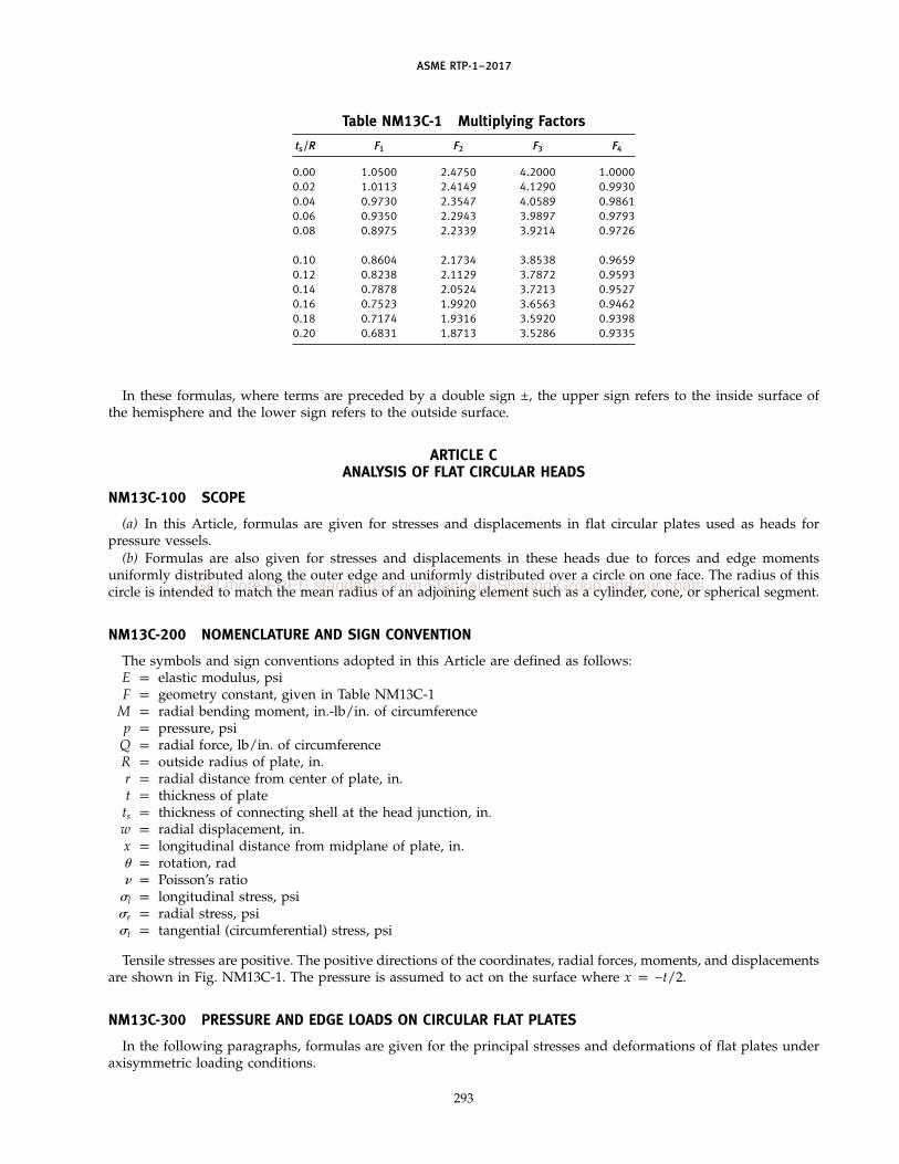
ASME RTP-1–2017
Table NM13C-1 Multiplying Factors
ts/R F1 F2 F3 F4
0.00 1.0500 2.4750 4.2000 1.00000.02 1.0113 2.4149 4.1290 0.99300.04 0.9730 2.3547 4.0589 0.98610.06 0.9350 2.2943 3.9897 0.97930.08 0.8975 2.2339 3.9214 0.9726
0.10 0.8604 2.1734 3.8538 0.96590.12 0.8238 2.1129 3.7872 0.95930.14 0.7878 2.0524 3.7213 0.95270.16 0.7523 1.9920 3.6563 0.94620.18 0.7174 1.9316 3.5920 0.93980.20 0.6831 1.8713 3.5286 0.9335
In these formulas, where terms are preceded by a double sign ±, the upper sign refers to the inside surface ofthe hemisphere and the lower sign refers to the outside surface.
ARTICLE CANALYSIS OF FLAT CIRCULAR HEADS
NM13C-100 SCOPE
(a) In this Article, formulas are given for stresses and displacements in flat circular plates used as heads forpressure vessels.
(b) Formulas are also given for stresses and displacements in these heads due to forces and edge momentsuniformly distributed along the outer edge and uniformly distributed over a circle on one face. The radius of thiscircle is intended to match the mean radius of an adjoining element such as a cylinder, cone, or spherical segment.
NM13C-200 NOMENCLATURE AND SIGN CONVENTION
The symbols and sign conventions adopted in this Article are defined as follows:E p elastic modulus, psiF p geometry constant, given in Table NM13C-1
M p radial bending moment, in.-lb/in. of circumferencep p pressure, psi
Q p radial force, lb/in. of circumferenceR p outside radius of plate, in.r p radial distance from center of plate, in.t p thickness of plate
ts p thickness of connecting shell at the head junction, in.w p radial displacement, in.x p longitudinal distance from midplane of plate, in.� p rotation, rad� p Poisson’s ratio
�l p longitudinal stress, psi�r p radial stress, psi�t p tangential (circumferential) stress, psi
Tensile stresses are positive. The positive directions of the coordinates, radial forces, moments, and displacementsare shown in Fig. NM13C-1. The pressure is assumed to act on the surface where x p −t/2.
NM13C-300 PRESSURE AND EDGE LOADS ON CIRCULAR FLAT PLATES
In the following paragraphs, formulas are given for the principal stresses and deformations of flat plates underaxisymmetric loading conditions.
293
Get more FREE standards from Standard Sharing Group and our chats

ASME RTP-1–2017
NM13C-310 Pressure Loads on Simply Supported Flat Plates
The principal stresses and deformations for a flat plate, simply supported at its periphery and loaded in themanner shown in Fig. NM13C-2, are given for a radial location, r, at any point, x, in the cross section by thefollowing formulas:
(a) Radial Bending Stress
�r p p3(x)
4t3[(3 + �)(R2 − r2)] (1)
(b) Tangential Bending Stress
�t p p3(x)
4t3[(3 + �)R2 − (1 + 3�)r2] (2)
(c) Longitudinal Stress
�l ppt x −
t2 (3)
(d) Rotation of the Midplane
� p −p3(1 − �)
4t3E[r3(1 + �) − rR2(3 + �)] (4)
(e) Rotation of the Midplane at the Outer Edge
� p +p3(1 − �)
2E Rt 3
(5)
(f) Radial Displacement
w p +(x)� (6)
NM13C-320 Edge Loads on Flat Plates
The principal stresses and deformations of a flat plate subjected to uniformly distributed edge loads, as shownin Fig. NM13C-3, are given for radial location r at any point x in the cross section by the following formulas:
(a) Radial and Tangential Stresses
�r p �t pQ
t−
12(x)
t3M (1)
(b) Rotation of the Midplane
� p−12(1 − �)(r)
Et3M (2)
(c) Radial Displacement
w p(1 − �)(r)
EtQ + (x)� (3)
NM13C-400 FLAT PLATE PRESSURE VESSEL HEADS
Flat plates used as pressure vessel heads are attached to a vessel shell in the manner shown by the typicalexamples in Fig. NM13C-4.
Since the support conditions at the edge of the plate depend upon the flexibility of the adjoining shell, the stressdistribution in the plate is influenced by the shell thickness and geometry. The structure formed by the head andthe shell may be analyzed according to the principles of discontinuity analysis described in Article D. In thefollowing paragraphs, formulas are given for the quantities necessary to perform a discontinuity analysis.
294
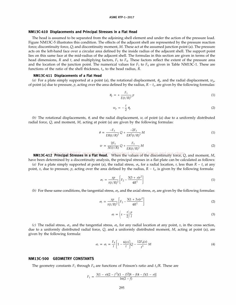
ASME RTP-1–2017
NM13C-410 Displacements and Principal Stresses in a Flat Head
The head is assumed to be separated from the adjoining shell element and under the action of the pressure load.Figure NM13C-5 illustrates this condition. The effects of the adjacent shell are represented by the pressure reactionforce; discontinuity force, Q; and discontinuity moment, M. These act at the assumed junction point (a). The pressureacts on the left-hand face over a circular area defined by the inside radius of the adjacent shell. The support pointlies on this same face at the mid-radius of the adjacent shell. The formulas in this section are given in terms of thehead dimensions, R and t, and multiplying factors, F1 to F4. These factors reflect the extent of the pressure areaand the location of the junction point. The numerical values for F1 to F4 are given in Table NM13C-1. These arefunctions of the ratio of the shell thickness, ts, to the head radius, R.
NM13C-411 Displacements of a Flat Head(a) For a plate simply supported at a point (a), the rotational displacement, �p, and the radial displacement, wp,
of point (a) due to pressure, p, acting over the area defined by the radius, R − ts, are given by the following formulas:
�p p +F1
E(t/R)3p (1)
wp p −t2
�p (2)
(b) The rotational displacements, �, and the radial displacement, w, of point (a) due to a uniformly distributedradial force, Q, and moment, M, acting at point (a) are given by the following formulas:
� p−F3
ER(t/R)2Q +
−2F3
ER2(t/R)3M (1)
w p2F3
3E(t/R)Q +
F3
ER(t/R)2M (2)
NM13C-412 Principal Stresses in a Flat Head. When the values of the discontinuity force, Q, and moment, M,have been determined by a discontinuity analysis, the principal stresses in a flat plate can be calculated as follows:
(a) For a plate simply supported at point (a), the radial stress, �r, for a radial location, r, less than R − ts at anypoint, x, due to pressure, p, acting over the area defined by the radius, R − ts, is given by the following formula:
�r pxp
t(t/R)2 �F2 −3(3 + �)r2
4R2 � (1)
(b) For these same conditions, the tangential stress, �t, and the axial stress, �l, are given by the following formulas:
�t pxp
t(t/R)2 �F2 −3(1 + 3�)r2
4R2 � (2)
�l p x −t2 p
t(3)
(c) The radial stress, �r, and the tangential stress, �t, for any radial location at any point, x, in the cross section,due to a uniformly distributed radial force, Q, and a uniformly distributed moment, M, acting at point (a), aregiven by the following formula:
�r p �t pF4
t �1 −6(x)
t �Q −12F4(x)
t3M (4)
NM13C-500 GEOMETRY CONSTANTS
The geometry constants F1 through F4 are functions of Poisson’s ratio and ts/R. These are
F1 p3(1 − �)(2 − f 2)(1 − f)2[8 − f(4 − f)(1 − �)]
16(2 − f)
295
Get more FREE standards from Standard Sharing Group and our chats
ASME RTP-1–2017
F2 p 3⁄8 (1 − f)2 �(1 − �)(2 − f 2) + 4(1 + �) �1 + 2 ln 2 − f2 − 2f��
F3 p 3⁄8 (1 − �)(2 − f)[8 − f(4 − f)(1 − �)]
F4 p 1⁄8 [8 − f(4 − f)(1 − �)]
In these expressions
f p ts/R
Table NM13C-1 lists these functions for various values of ts/R. These tabular values have been computed using0.3 for Poisson’s ratio.
NM13C-600 STRESS INTENSITIES IN A FLAT PLATE
The principal stresses due to pressure, p; discontinuity force, Q; discontinuity moment, M; and other coincidentloadings should be combined algebraically and the stress differences determined according to the procedures ofSubpart 3B. The calculated stress intensity values should not exceed the allowable values given in Subpart 3B.
ARTICLE DDISCONTINUITY STRESSES
NM13D-100 GENERAL
(a) Pressure vessels usually contain regions where abrupt changes in geometry, material, or loading occur. Theseregions are known as discontinuity areas and the stresses associated with them are known as discontinuity stresses.The discontinuity stresses are required to satisfy the compatibility of deformations of these regions.
(b) This Article describes a general procedure for analyzing the discontinuity stresses. A numerical example isincluded to illustrate the procedure.
(c) To determine the principal stresses at a discontinuity, it is necessary to evaluate the stresses caused by(1) pressure(2) mechanical loads(3) thermal loads(4) discontinuity loads
The stress intensities are then obtained by superposition of the stresses according to the rules given in para. 3B-400.
NM13D-200 INFORMATION REQUIRED
In order to perform a discontinuity analysis, the following information must be known:(a) the dimensions of the vessel(b) the material properties (E, �) of the component parts of the vessel (symbols as in para. NM13B-200)(c) mechanical loads, such as pressure, dead weight, bolt loads, and pipe loads(d) temperature distribution in the component parts
NM13D-300 METHOD OF ANALYSIS
(a) The analysis of a pressure vessel containing discontinuity areas can be performed in a standard mannersimilar to the analysis of any statically indeterminate structure. The analysis is initiated by separating the vesselinto shell elements of simple geometry (such as rings, cylinders, etc.) of which the structural behavior is known.The pressure, mechanical, and thermal loads acting on the structure are applied to the shell elements with a systemof forces required to maintain the static equilibrium of each element. These loads and forces cause individualelement deformations, which in general are not equal at the adjoining edges. The deformations at an element edgeare defined as
(1) radial displacement(2) rotation of meridian tangent
296

ASME RTP-1–2017
A redundant moment and shear force must generally exist on the edges of the elements in order to have compatibilityof deformations and restore continuity in the structure.
(b) At each juncture discontinuity, two equations can be written that express the equality of the combineddeformations due to all the applied loads and the redundant forces and moments. One equation will express theequality of rotation; the other equation, the equality of displacement of the adjacent elements. The resulting systemof simultaneous equations can be solved to obtain the redundant moment and shear force at each juncture.
NM13D-310 Procedure for Discontinuity Analysis
The following are the basic steps to follow for determining the redundant shear and moment that may exist ata pressure vessel discontinuity:Step 1: Separate the vessel into individual shell elements at locations of discontinuity.Step 2: Calculate the edge deformations of each element caused by a unit shear force and a unit moment at each
edge. These values are known as influence coefficients. The deformations due to local flexibilities may beconsidered in the calculation of these influence coefficients.
Step 3: Calculate the edge deformations of each element caused by loads other than redundant loads.Step 4: Calculate the edge deformations of each element caused by the temperature distributions.Step 5: At each juncture of two elements, equate the total radial displacements and the total rotations of each
element.Step 6: Solve the final system of simultaneous equations for the redundant shears and moments.
NM13D-320 Stresses
When the values of the redundant shear forces and moments have been determined, the stresses resulting from theredundant loadings may be computed by conventional methods. The final stresses for each element are determined bycombining these stresses with the stresses that would exist in the individual shell elements of Step 1.
NM13D-400 EXAMPLE ILLUSTRATING THE APPLICATION OF PARAGRAPH NM13D-310
NM13D-410 Given
A pressure vessel as shown in Figs. NM13D-1 and NM13D-2. It is constructed of all-mat RTP subjected to aninternal pressure of 15 psig. The vessel consists of
(a) a hemispherical head, inside radius R p 30 in., thickness t p 0.5 in.(b) a cylindrical shell, inside radius R p 30 in., thickness t p 0.5 in., length L p 10 in.(c) a flat head, outside radius R p 30.5 in., thickness t p 6 in.Material properties assumed are
E p 106 psi
� p 0.3
NM13D-420 Required
To calculate the discontinuity stresses at the locations of structural discontinuity.
NM13D-430 Solution
Step 1: Separate the vessel at locations of discontinuity into individual elements.Step 2: Calculate the influence coefficients.
(a) Element A, Hemispherical Head. From para. NM13B-420(b), the lateral displacement and rotation atjunction O due to edge loads, Qo and Mo, are given as
wAO p �AO p −2REt
Qo +22
EtMo
�AO p −22
EtQo +
43
REtMo
NOTE: For this case of a hemispherical shell, the lateral force, H, and radial force, Q, are equal. Similarly, the lateraldisplacement, �, and the radial displacement, w, are equal.
297
Get more FREE standards from Standard Sharing Group and our chats

ASME RTP-1–2017
Substituting the given dimensions and material properties gives
wAO p �AO p (−12.097725Qo + 3.9984962Mo) � 10−4
�AO p (−3.9984962Qo + 2.6431369Mo) � 10−4
(b) Element B, Cylindrical Shell. From paras. NM13A-320(a) and (b), the radial displacements and rotationsat the edges, O and L, due to edge loadings, Qo, Mo, QL, and ML, are given as1
wBO p (1/2�3D)Qo + (1/2�2D)Mo
−�BO p (1/2�2D)Qo + (1/�D)Mo
wBL p (1/2�3D)QL + (1/2�2D)ML
�BL p (1/2�2D)QL + (1/�D)ML
Substituting given dimensions and material properties gives
wBO p (12.097725Qo + 3.9984962Mo) � 10−4
−�BO p (3.9984962Qo + 2.6431369Mo) � 10−4
wBL p (12.097725QL + 3.9984962ML) � 10−4
�BL p (3.9984962QL + 2.6431369ML) � 10−4
(c) Element C, Flat Head. From para. NM13C-411(b), the radial displacement and rotation at juncture Ldue to edge loadings, QL and ML, are given as
wCL p −2F3
3E(t/R)QL +
F3
ER(t/R)2ML
�CL pF3
ER(t/R)2QL −
2F3
ER2(t/R)3ML
Substituting given dimensions and material properties gives
wCL p (−14.036001QL + 3.5090003ML) � 10−6
�CL p (3.5090003QL − 1.1696668ML) � 10−6
Step 3: Calculate the edge deformations due to the internal pressure.(a) Element A, Hemispherical Shell (See Fig. NM13D-3). The lateral displacement of point O at the midsur-
face of a hemispherical shell subjected to internal pressure is given by the expression
wo p �o p pR2(1 − �)/2Et
Substituting the dimensions, pressure, and material properties gives
wAO(pressure) p 0.009767625 in.
There is no rotation resulting from the internal pressure and membrane forces as shown
�AO(pressure) p 0
(b) Element B, Cylindrical Shell (See Fig. NM13D-4). The radial displacement of the midsurface of a closedend cylindrical shell subjected to internal pressure is given by the expression
wBO p 1 −�2 pR2
Et
Substituting the dimensions, pressure, and material properties gives
wBO(pressure) p wBL(pressure) p 0.02314125 in.
1 Note that 3/� p 9.076 in., which is less than the length L p 10 in. Then by para. NM13A-320(b), B11 p B12 p 1, B22 p 2, andG11 p G12 p G22 p 0.
298

ASME RTP-1–2017
There is no rotation resulting from the internal pressure and membrane forces as shown
�BO(pressure) p �BL(pressure) p 0
(c) Element C, Flat Head (See Fig. NM13D-5). In Article C, the rotation of a flat head at point L due tointernal pressure is given by para. NM13C-411(a)
� pF1
E(t/R)3p
Substituting the dimensions, pressure, and material properties gives
�CL(pressure) p 2.006336 � 10−3 rad
The radial displacement at juncture L is given by para. NM13C-411(a)
wCL(pressure) p −t2
�CL p −6.0190082 � 10−3 in.
Step 4: Calculate the free deformations of the edges of each element caused by temperature distributions.In this example, all parts of the vessel are at the same temperature and are of the same material;
therefore, temperature deformations need not be considered.Step 5: Equate the total lateral displacements and rotations of adjacent elements at each juncture.
(a) Juncture O
wAO(total) p wBO(total)
(−12.097725Qo + 3.9984962Mo + 97.67625) � 10−4 p (12.097725Qo + 3.9984962Mo + 231.4125) � 10−4 (1)
�AO(total) p �BO(total)
(−3.9984962Qo + 2.6431369Mo) � 10−4 p (−3.9984962Qo − 2.6431369Mo) � 10−4 (2)
(b) Juncture L
wBL(total) p wCL(total)
(12.097725QL + 3.9984962ML + 231.4125) � 10−4 p (−0.014036001QL + 0.03509ML − 60.90082) � 10−4 (3)
�BL(total) p �CL(total)
(3.9984962QL + 2.6431369ML) � 10−4 p (0.03509QL − 0.01169668ML + 20.063361)�10−4 (4)
Combining like terms and multiplying through by 104 results in the following system of simultaneousequations which express compatibility at the junctures:
24.19545Qo p −133.73625 (5)
5.2862738Mo p 0 (6)
12.238085QL + 3.9634062ML p −292.31332 (7)
3.9634062QL + 2.6548335ML p 20.063361 (8)
Step 6: Solve the above equations for Qo, Mo, QL, and ML. The results are
Qo p −5.52733 lb/in.
Mo p 0
QL p −50.98251 lb/in.
299
Get more FREE standards from Standard Sharing Group and our chats

ASME RTP-1–2017
ML p 83.669186 in.-lb/in.
NOTE: A negative sign indicates that the actual direction of the loading is opposite to that chosen in Step 1.
Step 7: Compute the discontinuity stresses at each juncture due to the redundants Qo, Mo, QL, and ML.To illustrate the procedure, these stresses will be computed in the cylindrical shell (element B) at both
junctures, O and L.From para. NM13A-330,
�l(x) p ±6M(x)/t2
�t(x) pEw(x)
R + t/2±
6�M(x)
t2
�r p 0
(a) Juncture O. At juncture O, M(x) p Mo and w(x) p wo.
NOTE: When computing �t(x), only the radial displacement due to the redundant shear forces and moments should beused. The free displacements from Steps 3 and 4 should not be included.
wBO p (12.097725Qo + 3.9984962Mo) � 10−4 p −0.006686812 in.
EwBO p −6,686.81 lb/in.
Mo p 0
(1) Inside surface
�l p 6(0)/(0.5)2 p 0
�t p−6,686.81
30.25+ 6(0.3)(0)/(0.5)2 p −221.1 psi
�r p 0
(2) Outside surface
�l p −6(0)/(0.5)2 p 0
�t p−6,686.81
30.25− 6(0.3)(0)/(0.5)2 p −221.1 psi
�r p 0
(b) Juncture L. At juncture L, M(x) p ML and w(x) p wL.
wBL p (12.097725QL + 3.9984962ML) � 10−4 p −0.028222 in.
EwBL p −28,222.1 lb/in.
ML p 83.669186 in.-lb/in.
(1) Inside surface
�l p 6(83.669186)/(0.5)2 p 2,008.1 psi
�t p−28,222.1
30.25+ 6(0.3)(83.6692)/(0.5)2 p −330.54 psi
�r p 0
300
ASME RTP-1–2017
(2) Outside surface
�l p −6(83.6692)/(0.5)2 p −2,008.1 psi
�t p−28,222.1
30.25− 6(0.3)(83.6692)/(0.5)2 p −2,941.02 psi
�r p 0
NOTE: E p 106 psi.
(c) The discontinuity stresses in the hemispherical shell may be computed by using the expressionsgiven in paras. NM13B-410 and NM13B-430.
(d) The discontinuity stresses in the flat head may be computed using the expressions given inpara. NM13C-412.
Step 8: Compute the total stresses. The total stresses may be computed in any element at any juncture by combiningthe stresses due to the redundant shear forces and moments, as computed in Step 7, with the stressesresulting from all other loadings. In this case, the stresses in the cylindrical shell, hemispherical shell, andflat head due to internal pressure may be computed by using the expressions given in paras. NM13A-210,NM13B-310, and NM13C-412, respectively. To illustrate the procedure, the total stresses in the cylindricalshell at junctures O and L will be computed.
The stresses in the cylindrical shell due to internal pressure may be computed from the expressionsgiven in para. NM13A-210
�l p pR/2t
�t p pR/t
�r p 0
(a) Juncture O(1) Inside surface
R p 30.25 in.
p p 15 psig
�l p 453.8 psi
�t p 907.5 psi
�r p 0
The stresses due to the redundant shear forces and moments were computed in Step 7 as
�l p 0
�t p −221.1 psi
�r p 0
The total stresses are
�l p 453.8 + 0 p 453.8 psi
�t p 907.5 − 221.1 p 686.4 psi
�r p 0
(2) Outside surface, from pressure
�l p 453.8 psi
301
Get more FREE standards from Standard Sharing Group and our chats

ASME RTP-1–2017
�t p 907.5 psi
�r p 0
The stresses due to the redundant shear forces and moments were computed as
�l p 0
�t p −221.1 psi
�r p 0
The total stresses are
�l p 453.8 psi
�t p 907.5 − 221.1 p 686.4 psi
�r p 0
(b) Juncture L(1) Inside Surface. The stresses due to the internal pressure are the same as at juncture O
�l p 453.8 psi
�t p 907.5 psi
�r p 0
The stresses due to the redundant shear forces and moments are
�l p 6(83.669)/(0.5)2 p 2,008 psi
�t p−106(2.8222 � 10−2)
30.25+
6(0.3)(83.669)
(0.25)2p 1,476 psi
�r p 0
The total stresses are
�l p 453.8 + 2,008 p 2,462 psi
�t p 907.5 + 1,476 p 2,383 psi
�r p 0
(2) Outside Surface. The stresses due to the internal pressure are the same as at juncture O
�l p 453.8 psi
�t p 907.5 psi
�r p 0
The stresses due to redundant shear forces and moments are
�l p −6(83.669)/(0.5)2 p −2,008 psi
�t p−106(2.8222 � 10−2)
30.25−
6(0.3)(83.669)
(0.25)2p −3,342.6 psi
�r p 0
302

ASME RTP-1–2017
The total stresses are
�l p 453.8 − 2,008 p −1,554 psi
�t p 907.5 − 3,342.6 p −2,435.1 psi
�r p 0
Step 9: When evaluating the stresses in accordance with para. M3-500, the strength ratios at each location shouldbe computed from the total principal stresses determined in Step 8.
303
Get more FREE standards from Standard Sharing Group and our chats

ASME RTP-1–2017
Fig. NM13A-1 Sign Conventions forCylindrical Segments
x
Qo, Mo Q (x), M (x)
+ w+
x = 0 x = x x = x x = L
R
QL, ML
θ
t
304
Fig. NM13B-1 Sign Conventions for SphericalSegments
α
oφL
L
φ
XR
t
c
Mo
o
o
RmR
Ho
++
δ
α
φ
oφ
φ
θ
Spherical segment, for values of
(a)
(b)
(c)
0.9 rad ≤ (1 − )λ
π, radπ,
:
0.9λ
≤
oφ (1 − ) rad, and ( )π, π/λ, rad0.9λ
≤ ≥
t
c
c
o
Rm
Ho
Mo
Mo
Ho
++ δ
+ δ
α φ
oφ
θ
+ θ
Hemisphere for = π/2, rad
oφ φFrustum, for values of :−
Loφ φ−

ASME RTP-1–2017
Fig. NM13C-1 Sign Conventions for Flat Plates
t
+x
+ Q + W+ M
+ θ
rR p
Fig. NM13C-2 Simply Supported Flat Plate
x R
r
p
Simplesupport
Fig. NM13C-3 Edge Loads on Flat Plates
Q
M
+ x R
r
t
305
Fig. NM13C-4 Flat Plate Vessel Head
R − ts
R R R
R − ts R − ts
tsts ts
Fig. NM13C-5 Flat Plate to Cylinder Joint
R − ts R − tsr
t
R
Q
p
M
x
ts
Reaction force
Supportpoint (a)
Fig. NM13D-1 Example Pressure Vessel
10.000 in. = L
30.5
in. =
R
30.0
00 in
. = R
30.000 in. = R
p = 15 psig
t 6 in.
0.5 in. = t
Get more FREE standards from Standard Sharing Group and our chats

ASME RTP-1–2017
Fig. NM13D-2 Forces and Moments in PressureVessel Example
φo = 90 deg
R = 30.25 in.
10 in.
R =
30.
5 in
.
R =
30.
25 in
. 6 in.
0.5 in.
0.5 in.
Juncture O
Element A
Element B
Element C
Qo
QoMo MLMLQL
QL
Mo
Juncture L
Fig. NM13D-3 Hemispherical Head
Point O
pR2
R
tp
Fig. NM13D-4 Cylindrical Shell
R
Point LPoint O
pR
p
2pR2
306
Fig. NM13D-5 Flat Plate Head
RR − ts
Point L
p (R − ts)2
ts
t
2 [R − (ts /2)]

ASME RTP-1–2017
NONMANDATORY APPENDIX NM-14
DELETED
307
(17)
Get more FREE standards from Standard Sharing Group and our chats

ASME RTP-1–2017
NONMANDATORY APPENDIX NM-15FLAT CORED PLATE DESIGN
NM15-100 CORED PLATE DESIGN
The design method for cored plates given in thisAppendix begins by determining the thickness of a solidplate which will meet the stress and deflection criteria.If the required solid plate thickness is greater than 3⁄4 in.,a cored design should be considered. In the following,the effect of the core is used in the calculation of theeffective flexural modulus but not in the calculation ofthe facial stress. If the core material is end grain balsa,both effects are negligible. The plates considered in thisAppendix are assumed to act only in bending, with nostiffening due to membrane action.
NM15-110 Solid Plate Design
For most simple geometries and loadings, the solutionis available in analytical form or in terms of a correlationequation. For more complex cases, a finite elementmodel may be necessary. For thick plates, the elasticproperties and allowable bending stress are almost con-stant and may be obtained either from Table 2A-3 orusing the methods of Mandatory Appendix M-3. In anycase, both stress and deflection limited thicknessesshould be calculated and the thicker used as the solidplate thickness, Ts.
NM15-120 Initial Estimate of Core Thickness
Core thickness, Tc, should be in the order of the solidplate thickness, Ts, and available either in full thicknessor readily built up of thinner layers bonded together.For each core thickness, a face thickness is determinedthat will meet the stress and deflection criteria (seeFig. NM15-1).
NM15-130 Plate Deflections and Stresses
For a plate of constant thickness and material proper-ties, the plate deflection is expressed as a function ofthe geometry, loading, and boundary conditions dividedby the bending rigidity. The moment resultants do notdepend upon bending rigidity and are constant for anyplate having the same geometry, loading, and boundaryconditions.
Since loading and geometry do not change, the deflec-tion of any other plate may be obtained in terms of thefirst by multiplying it by the inverse ratio of their bend-ing rigidities. This may be used to determine the deflec-tion of a cored plate if its bending rigidity can becalculated. Using the overall thickness of the cored plateas a basis, this is possible if an effective flexural modulus
308
can be estimated. For assumed values of core thickness,Tc, and face thickness, Tf, calculate the overall thickness,To, and the effective flexural modulus of the coredplate, Ecp.
Ecp, psi p24
T3o�EffTf
3
12+
EftTf
4(Tc + Tf)2� + EcTc
To3
To, in. p Tc + 2Tf
whereEc p modulus of the core in a direction parallel to
the facesEff p flexural modulus of the faceEft p tensile modulus of the face
NM15-140 Calculate Plate Deflection, �cp; FacialStress, �cp; and Core Stress, �cc
�cp, in. p �s EsT3s
EcpT3o
�cp, psi p �s ToT2s
T3o − T3
c
�cc, psi p �cp Tc
Tc + TfEc
Eftwhere
Es p flexural modulus of laminate�s p maximum deflection�s p maximum stress
NM15-150 Calculate Shear Stress at the Bond Line(Tmax)
Tmax, psi p6(TcTf + T2
f )
T3o − T3
c
Vmax
whereVmax p shear resultant, lb/in.
NM15-160 Design Optimization
For a given core thickness, the design may be opti-mized by changing the thickness of the face andrepeating the calculations. If the face thickness becomesexcessive, the core thickness is changed.

ASME RTP-1–2017
Fig. NM15-1 Equivalent Solid and Cored Plates
Ts
Tf
Tf
ToTc
(a) Solid Plate
(b) Cored Plate
Face
Face
Core
NM15-170 Design Example
Design a cored flat bottom for an 8 ft diameter tankoperating at a vacuum of 60 in. water column (2.17 psi).The maximum deflection is specified to be 1.0 in. andthe maximum stress not to exceed 2,200 psi. The bottomis conservatively assumed to have simply supportededges. By trial it is found that the design conditionsare satisfied for a solid plate thickness of 2 in. FromTable 2A-3, the flexural modulus for hand lay-up con-struction is Es p 1�106 psi for all thicknesses over 3⁄8 in.For this calculation, Poisson’s ratio � p 0.3.
(a) For the Solid Plate(1) Bending rigidity
D pEsT
3
12(1 − �2)
p1�106(2.0)3
12[1 − (0.3)2]p 7.326�105
(2) Maximum deflection
�s p PR4 5 + �64D(1 + �)
p[2.17(48)4](5.3)
64(7.326�105)(1.3)p 1.002 in.
(3) Maximum stress
�s p3PR2
8T2(3 + �)
p3(2.17)(48)2
8(2.0)2(3.3) p 1,547 psi
309
(4) Maximum shear resultant
Vmax pPR2
p(2.17)(48)
2p 52 lb/in.
(b) For the Cored Plate. Estimate the core and facethicknesses as 1.75 in. and 0.375 in. The end grain balsacore is assumed to have a density of 15.5 lb/ft3 and havea modulus of 50,000 psi perpendicular to the grain. FromTable 2A-3, the flexural modulus of the face Eff p1�106 psi and its tensile modulus Eft p 1.5�106 psi.
(1) Plate thickness
To p Tc + 2Tf p 1.75 + 2(0.375) p 2.5 in.
(2) Flexural modulus
Ecp p24
T3o�EffTf
3
12+
EftTf
4(Tc + Tf)2� + EcTc
To3
p24
(2.5)3�(1�106)(0.375)3
12
+(1.5�106)(0.375)
4(1.75 + 0.375)2�
+ (50�103)1.752.5
3
p 9.99�105 psi
(3) Maximum deflection
�cp p �s EsT3s
EcpT3o
p (1.0)1�106(2.0)3
9.99�105(2.5)3p 0.513 in.
Get more FREE standards from Standard Sharing Group and our chats

ASME RTP-1–2017
(4) Maximum face stress
�cp p �s ToT2s
T3o − T3
c
p (1,547)(2.5)(2.0)2
(2.5)3 − (1.75)3p 1,507 psi
(5) Maximum core stress
�cc p �cp Tc
Tc + TfEc
Eftp 1,507 1.75
1.75 + 0.37550�103
1.5�106 p 41 psi
(6) Maximum shear resultant
Vmax pPR2
p(2.17)(48)
2p 52.1 lb/in.
310
whereP p pressureR p radius
(7) Maximum bond shear
Tmax p 6VmaxTcTf + T2f
T3o − T3
c
p 6(52.1)(1.75)(0.375) + (0.375)2
(2.5)3 − (1.75)3p 24.3 psi
NM15-180 Discussion
This design method assumes that the face laminatesare equal and therefore the neutral axis lies at the centerof the cored plate. However, it may be extended toinclude unequal face laminates. The effect of Poisson’sratio � on the bending rigidity of the cored plate hasbeen neglected as second order.

ASME RTP-1–2017
NONMANDATORY APPENDIX NM-16EXTERNAL PRESSURE DESIGN EXAMPLE
FOR CYLINDRICAL SHELLS
NM16-100 INTRODUCTION
This Appendix demonstrates the use of the rigorous NASA SP-8007 solution and the simplified equation forcylinder buckling due to external pressure in para. 3A-300. The following laminate is used for evaluation purposes:
Material(Top to Bottom) E1, psi E2, psi �12 G12, psi t, in.
Veil 550,000 550,000 0.34 200,000 0.013Two mats 1,030,000 1,030,000 0.34 390,000 0.086(+/– 54)3 1,140,000 1,600,000 0.45 1,000,000 0.127Mat 1,030,000 1,030,000 0.34 390,000 0.043Woven roving 2,296,640 1,957,986 0.124 270,000 0.039Mat 1,030,000 1,030,000 0.34 390,000 0.043
From this the classical laminate theory ABD matrix is calculated as follows:
ABD p �501,426.04 208,198.05 0.00 −5,608.95 1,262.41 0.00208,198.05 569,659.28 0.00 1,262.41 −3,035.67 0.00
0.00 0.00 207,210.00 0.00 0.00 1,118.52−5,608.95 1,262.41 0.00 4,662.20 1,400.18 0.001,262.41 −3,035.67 0.00 1,400.18 4,613.11 0.00
0.00 0.00 1,118.52 0.00 0.00 1,391.70�
The ABD inverse matrix (required for the simplified equation) is then
ABD–1 p �2.42021 � 10−6 −9.06151 � 10−7 0 3.88959 � 10−6 −2.43918 � 10−6 0
−9.06151 � 10−7 2.10438 � 10−6 0 −2.36602 � 10−6 2.35091 � 10−6 0
0 0 4.84705 � 10−6 0 0 −3.89561 � 10−6
3.88959 � 10−6 −2.36602 � 10−6 0 2.42724 � 10−4 −7.62934 � 10−5 0
−2.43918 � 10−6 2.35091 � 10−6 0 −7.62934 � 10−5 2.42145 � 10−4 0
0 0 −3.89561 � 10−6 0 0 7.21677 � 10−4
�NM16-200 NASA SP-8007 SOLUTION
The rigorous NASA SP-8007 solution is calculated as follows: The constants used in the NASA SP-8007 solutionare defined as
A11 p ABD1,1 A12 p ABD1,2 A16 p ABD1,3 A26 p ABD2,3 A22 p ABD2,2 A66 p ABD3,3
B11 p ABD4,1 B12 p ABD5,1 B16 p ABD6,1 B26 p ABD5,3 B22 p ABD5,2 B66 p ABD6,3
D11 p ABD4,4 D12 p ABD5,4 D16 p ABD6,4 D26 p ABD6,5 D22 p ABD5,5 D66 p ABD6,6
311
Get more FREE standards from Standard Sharing Group and our chats

ASME RTP-1–2017
The A11 term is the 1,1 term and the D11 term is the 4,4 term from the ABD matrix given above. Some values ofthe constants, given here to clarify the procedure, are
A11 p 501,426.04 A12 p 208,198.05 D11 p 4,662.20 D66 p 1,391.70 A66 p 207,210.00B12 p 1,262.41 B26 p 0
The cylinder dimensions and the buckling modes being evaluated are
R p 36.351 (outside radius, in.) L p 72 (design length between stiffeners, in.) FS p 5 (factor of safety)
m p 1, 2 . . ., 30 and n p 1, 2 . . ., 30 (modes in the hoop and axial directions, taking on integer values between 1 and 30;n starts at 2 for pressure loading and 4 for axial compression)
t p 0.351 (total thickness of laminate; this is required input for calculating effective mechanical propertiesfor the simplified equation, in.)
The preliminary calculations for the NASA SP-8007 equations for the first 30 � 30 modes are
C11 m,n p A11m�
L 2
+ A66nR
2
C22 m,n p A22nR
2
+ A66m�
L 2
C33 m,n p D11m�
L 4
+ 2(D12 + 2D66)m�
L 2
nR
2
+ D22nR
4
+A22
R2+
2B22
R nR
2
+2B12
R m�
L 2
C12 m,n p (A12 + A66)m�
L nR
C21 m,n p C12 m,n
C23 m,n p (B12 + 2B66)m�
L 2
nR +
A22
R nR + B22n
R3
C32 m,n p C23 m,n
C13 m,n pA12
R m�
L + B11m�
L 3
+ (B12 + 2B66)m�
L nR
2
C31 m,n p C13 m,n
The determinant of the matrix �C11 C12 C13C21 C22 C23C31 C32 C33
� can be calculated from
det Nm,n p C11 m,n (C22 m,n C33 m,n − C32 m,n C23 m,n) − C21 m,n (C12 m,n C33 m,n − C32 m,n C13 m,n)+ C31 m,n (C12 m,n C23 m,n − C22 m,n C13 m,n)
The determinant of the matrix �C11 C12C21 C22� can be calculated from
det Dm,n p C11 m,n C22 m,n − C21 m,n C12 m,n
The critical pressure for lateral and longitudinal pressure is then calculated by varying the m and n integers toobtain the smallest value of Pa (allowable design lateral and longitudinal pressure) for the first 30 � 30 modes
Pa m,n pR
FS�n2 +12m�R
L 2
�det Nm,n
det Dm,n
312
ASME RTP-1–2017
For this example, the lowest modes are n p 6 and m p 1, and the allowable design buckling pressure including a5:1 factor of safety is
min (Pa) p 1.059
NM16-300 USING SIMPLIFIED EQUATION
The procedure for using the simplified equation per para. 3A-300 is as follows: The mechanical properties neededare calculated from
�1 p−(ABD−1)5,4
(ABD−1)4,4
p 0.314 �2 p−(ABD−1)5,4
(ABD−1)5,5
p 0.315
Eat pA11A22 − A12
2
A22tp 1,211,778 Eaf p
12
t3(ABD−1)4,4
p 1,143,266
Ehf p12
t3(ABD−1)5,5
p 1,146,001
where the constants used for calculation are from the ABD and ABD inverse matrices using the notation shownabove for the NASA SP-8007 solution. The allowable design external pressure is then calculated from
Zp pE3/2
hf E1/2at
Eaf2
(1 − �1�2)1/2 L2
Rtp 398.465 Do p 2R
� p (if Zp ≤ 100, 1 − 0.001Zp; otherwise 0.9) p 0.9 FS p 5 KD p 0.84
Pa p(KD)0.8531(�)E3/4
hf E1/4at t5/2
(1 − �1�2)3/4L(Do/2)3/2FSp 0.7498 psi
whereDo p outside diameter of shell, in.Eaf p axial flexural modulus, psiEat p axial tensile modulus, psiEhf p hoop flexural modulus, psiFS p design factor of safety p 5
KD p 0.84, a knockdown factor to cover all data points using the rigorous equationsL p design length of a vessel section, in.
Pa p allowable design buckling pressure with a factor of safety of 5�1 p flexural Poisson’s ratio in the axial direction�2 p flexural Poisson’s ratio in the hoop direction
313
Get more FREE standards from Standard Sharing Group and our chats

ASME RTP-1–2017
NONMANDATORY APPENDIX NM-17STIFFENER DESIGN CALCULATIONS
NM17-100 INTRODUCTION
This Appendix provides and demonstrates the equations and calculations for stiffeners to meet the requirementsof para. 3A-330 for external pressure or internal vacuum. This includes half-round, trapezoidal, and filament woundband configurations (see Figs. NM17-1 through NM17-3).
The difference in modulus between the shell and stiffener shifts the neutral axis of the stiffener and producesthe effective hoop modulus of the stiffener.
The bending boundary layer (BBL) in the shell is based on orthotropic shell theory, and the needed propertiescan be determined using the lamination analysis method given in Mandatory Appendix M-3 or other recognizedlaminate analysis programs per para. 3A-127.
NM17-200 STIFFENER MOMENT OF INERTIA FOR A HALF-ROUND
The following are equations and calculations for Fig. NM17-1:
Fig. NM17-1 Stiffener Moment of Inertia for a Half-Round
Ro
R
t and E
R
Taper no steeper than 1:6 (not included in calculations)
wes = 2BBL + 4R
ts and Es
Radius of stiffener: R p 3 in.
Thickness of stiffener: ts p 0.314 in.
Hoop modulus of stiffener: Es p 1.72 � 106 psi
Thickness of shell: t p 0.358 in.
Hoop modulus of shell: E p 2.443 � 106 psi
Axial flexural stiffness of shell: Da p 5,053 lb-in.
Hoop flexural stiffness of shell: Dh p 7,335 lb-in.
Extensional Poisson’s ratio for load in axial direction: vah p 0.1883
Extensional Poisson’s ratio for load in hoop direction: vha p 0.2717
Length between stiffeners as defined in para. 3A-330: Ls p 120 in.
Design factor: F p 5
External pressure: P p 4 psi
314

ASME RTP-1–2017
Internal diameter of shell: D p 60 in.
Outside diameter of shell: Do p D + 2t p 60.716 in.
BBL p 0.527 �Do
2� t � � 1
1 − �ah � �haDa
Dhp 1.604 in.
NOTE: Length of BBL in the shell where the stresses are 50% of the peak stresses; the ratio Da/Dh may be replaced with D11/D22 asdefined in Mandatory Appendix M-3.
Effective width of shell: wes p 2BBL + 4R p 15.207 in.
Outside radius of stiffener: Ro p R + ts p 3.314 in.
Area of shell wall: A p wes � t p 5.444 in.2
Area of buildup: Ab p 2(R − ts) � ts p 1.687 in.2
Area of half-round:
Ar p�
2� (Ro
2 − R2) p 3.114 in.2
Total area: At p A + Ab + Ar p 10.2453 in.2
Effective hoop modulus of shell and stiffener:
Eh pAE + Ab � Es + Ar � Es
Atp 2.104 � 106 psi
Required moment of inertia (MOI) for ring to prevent buckling for all the load carried by the stiffener:
Is pP � Ls � Do
3 � F24Eh
p 10.6371 in.4
Center of gravity (CG) shell wall relative to O.D. of shell:
CGw p−t2
p −0.1790 in.
CG of buildup relative to O.D. of shell:
CGb pts
2p 0.1570 in.
CG of half-round relative to O.D. of shell:
CGr p4
3��
Ro2 + Ro � R + R2
Ro + Rp 2.0115 in.
Effective CG relative to O.D. of shell:
CGe pCGw � A + CGb � Ab �
Es
E+ CGr � Ar �
Es
E
A + Ab �Es
E+ Ar �
Es
E
p 0.4105 in.
315
Get more FREE standards from Standard Sharing Group and our chats

ASME RTP-1–2017
I1 pwes � t3
12EEh
+2�(R − ts) � ts
3�12
�Es
Eh+ ��
8� (Ro
4 − R4) −8
9��
(Ro3 − R3)
2
Ro2 − R2 � Es
Ehp 2.496
I2 p A(CGe − CGw)2 �EEh
+ Ab(CGe − CGb)2 �Es
Eh+ Ar(CGr − CGe)2 �
Es
Ehp 8.81
Effective MOI considering the different moduli of the stiffener and shell: Ie p I1 + I2 p 11.306 in.4
Required MOI in stiffener from above: Is p 10.637 in.4
Effective MOI: Ie p 11.306 in.4
NOTE: Ie must be greater than Is to meet the requirements (IeEh > IsEh).
NM17-300 STIFFENER MOMENT OF INERTIA FOR A TRAPEZOIDAL STIFFENER
The following are equations and calculations for Fig. NM17-2:
Fig. NM17-2 Stiffener Moment of Inertia for a Trapezoidal Stiffener
A
C
DB
t and E
ts and Es
Taper no steeper than 1:6 (not included in calculations)
wes
wes = B + 2D + 2BBL
Width of stiffener at top: A p 3 in.
Width of stiffener at bottom: B p 6 in.
Height of stiffener: C p 3 in.
Width of overlay (should be ≥B/2): D p 3 in.
Thickness of stiffener: ts p 0.314 in.
Hoop modulus of stiffener: Es p 1.72 � 106 psi
Thickness of shell: t p 0.358 in.
Hoop modulus of shell: E p 2.443 � 106 psi
Axial flexural stiffness of shell: Da p 5,053 lb-in.
Hoop flexural stiffness of shell: Dh p 7,335 lb-in.
Extensional Poisson’s ratio for load in axial direction: vah p 0.1883
Extensional Poisson’s ratio for load in hoop direction: vha p 0.2717
316

ASME RTP-1–2017
Length between stiffeners as defined in para. 3A-330: Ls p 120 in.
Design factor: F p 5
External pressure: P p 4.0 psi
Internal diameter of cylinder: Dc p 60 in.
Outside diameter of shell: Do p Dc + 2t p 60.716 in.
BBL p 0.527 �Do
2� t � � 1
1 − �ah � �haDa
Dhp 1.604 in.
NOTE: Length of BBL in the shell where the stresses are 50% of the peak stresses; the ratio Da/Dh may be replaced with D11/D22 asdefined in Mandatory Appendix M-3.
Slope of sides:
� p acos� C
�C2 + B − A2
2� p 0.464 rad
�180�
p 26.565 deg
Length of sides:
L p �C2 + B − A2
2
p 3.354 in.
Area of sides:
As p 2�C2 + B − A2
2
� ts p 2.106 in.2
Effective width of cylinder: wes p 2BBL + B + 2D p 15.207 in.
Effective area of cylinder: Ac p wes � t p 5.444 in.2
Area of top: At p Ats p 0.942 in.2
Area of overlay: Ad p 2(D − ts)ts p 1.687 in.2
Total effective area of stiffener excluding shell: Atot p At + Ad + As p 4.735 in.2
Effective hoop modulus of stiffener and cylinder per rule of mixtures:
Eh pE � Ac + Es � Atot
Ac + Atotp 2.107 � 106 psi
Required MOI for ring to prevent buckling for all the load carried by the stiffeners:
Is pP � Ls � Do
3 � F24Eh
p 10.6246 in.4
Effective CG from outside of shell:
CG p
Ac �−t2
+ ts
2 �Es
E� Ad + AsC2 �
Es
E+ AtC +
ts
2 �Es
E
Ac + Atot �Es
E
p 0.402 in.
317
Get more FREE standards from Standard Sharing Group and our chats

ASME RTP-1–2017
I of each side about the centroid of the sides:
Iside p ts � L3
12 � cos(�)2 + L � ts3
12 sin(�)2 p 0.792 in.4
About the centroids:
I1 pwes � t3
12�
EEh
+
Es
Eh� Ad � ts
2
12+
Es
Eh� 2Iside +
Es
Eh� At � ts
2
12p 1.378 in.4
I2 p t � wesCG +t2
2
�EEh
+ Ad �Es
Eh� CG −
ts
22
+ As �Es
Eh C2 − CG2
+ At �Es
Eh� C +
ts
2− CG
2
p 10.124 in.4
Effective MOI considering different moduli of shell and stiffener: Ie p I1 + I2 p 11.502 in.4
Required MOI calculated above: Is p 10.6246 in.4
Effective MOI: Ie p 11.502 in.4
NOTE: Ie must be greater than Is to meet the requirements (IeEh > IsEh).
NM17-400 STIFFENER MOMENT OF INERTIA FOR A FILAMENT WOUND BAND
The following are equations and calculations for Fig. FM17-3:
Fig. NM17-3 Stiffener Moment of Inertia for a Filament Wound Band
w
Taper no steeper than 1:6 (not included in calculations)
wes = 2BBL + w
wes
ts and Es
t and E
Width of stiffener: w p 4 in.
Thickness of stiffener: ts p 0.25 in.
Hoop modulus of stiffener: Es p 5.2 � 106 psi
Thickness of shell: t p 0.358 in.
Hoop modulus of shell: E p 2.443 � 106 psi
Axial flexural stiffness of shell: Da p 5,053 lb-in.
Hoop flexural stiffness of shell: Dh p 7,335 lb-in.
Extensional Poisson’s ratio for load in axial direction: vah p 0.1883
Extensional Poisson’s ratio for load in hoop direction: vha p 0.2717
318

ASME RTP-1–2017
Length between stiffeners as defined in para. 3A-330: Ls p 120 in.
Design factor: F p 5
External pressure: P p 0.361 psi
Internal diameter of shell: D p 60 in.
Outside diameter of shell: Do p D + 2t p 60.716 in.
BBL p 0.527 �Do
2� t � � 1
1 − �ah � �ha �Da
Dhp 1.604 in.
NOTE: Length of BBL in the shell where the stresses are 50% of the peak stresses; the ratio Da/Dh may be replaced with D11/D22 asdefined in Mandatory Appendix M-3.
Effective width of shell: wes p 2BBL + w p 7.207 in.
Effective hoop modulus of stiffener:
Eh pE � t � wes + Es � ts � w
t � wes + ts � wp 3.213 � 106 psi
Required MOI for ring to prevent buckling for all the load carried by the stiffeners:
Is pP � Ls � Do
3 � F24Eh
p 0.6287 in.4
Effective CG from inside of tank wall:
CG p
t � wes �t2
+ t +ts
2 �Es
E� w � ts
wes � t + w �Es
E� ts
p 0.316 in.
Ie pwes � t3
12�
EEh
+
Es
Eh� w � ts
3
12+ t � wesCG −
t2
2
�EEh
+ ts �Es
Eh� wt +
ts
2− CG
2
p 0.1113 in.4
Required MOI calculated above: Is p 0.6287 in.4
Effective MOI: Ie p 0.1113 in.4
NOTE: Ie must be greater than Is to meet the requirements (IeEh > IsEh).
319
Get more FREE standards from Standard Sharing Group and our chats

ASME RTP-1–2017
SI UNITS
ASME RTP-1 is based on U.S. Customary (ft-lb) units of measurement that are to be regarded as the standard.This supplement is provided as a convenience to the Standard user and contains SI conversion factors for unitscontained in the Standard.
320

ASME RTP-1–2017
List of SI Units for Use With ASME RTP-1
Other Units orQuantity Unit Symbol Limitations
Space and TimePlane angle radian rad degree (decimalized)Length meter mArea square meter m2
Volume cubic meter m3 liter (L) for liquid only (use withoutprefix other than in milliliter, mL)
Time second s minute (min), hour (h), day (d),week, and year (yr)
Periodic and Related PhenomenaFrequency hertz Hz revolutions per second (r/s)Rotational frequency revolutions per second s−1 revolutions per minute (r/m)
MechanicsMass kilogram kgDensity kilogram per cubic meter kg/m3
Moment of inertia kilogram·meter2 kg·m2
Force newton NMoment of force (torque) newton-meter N·mPressure and stress pascal Pa (pascal p newton per square meter)Energy, work joule J kilowatt-hour (kW·h)Power watt WImpact strength joule JSection modulus meter3 m3
Moment of section meter4 m4
(second moment of area)Fracture toughness Pa·�m
HeatTemperature — thermodynamic kelvin K degree Celsius (°C)
[Note (1)]Temperature — other than degree Celsius °C kelvin (K)
thermodynamicLinear expansion coefficient meter per meter-kelvin K−1 °C−1
Quantity of heat joule JHeat flow rate watt WThermal conductivity watt per meter-kelvin W/(m·K) W/(m·°C)Thermal diffusivity square meter per second m2/sSpecific heat capacity joule per kilogram-kelvin J/(kg·K) J/(kg·°C)
Electricity and MagnetismElectric current ampere AElectric potential volt VCurrent density ampere per meter2 A/m2
Magnetic field strength ampere per meter A/m
GENERAL NOTE: Conversion factors between SI units and U.S. Customary are given in SI-1, “ASME Orientation and Guide for Use of SI (Metric)Units,” and IEEE/ASTM SI-10.
NOTE:(1) Preferred use for temperature and temperature interval is degrees Celsius (°C), except for thermodynamic and cryogenic work where kel-
vins may be more suitable. For temperature interval, 1 K p 1°C exactly.
321
Get more FREE standards from Standard Sharing Group and our chats

ASME RTP-1–2017
Commonly Used Conversion Factors
Multiply byQuantity To Convert From To [Notes (1), (2)]
Plane angle degree rad 1.745 329 E−02
Length in. m 2.54* E−02ft m 3.048* E−01yd m 9.144* E−01
Area in.2 m2 6.451 6* E−04ft2 m2 9.290 304* E−02yd2 m2 8.361 274 E−01
Volume in.3 m3 1.638 706 E−05ft3 m3 2.831 685 E−02U.S. gallon m3 3.785 412 E−03Imperial gallon m3 4.546 09 E−03liter m3 1.0* E−03
Mass lbm kg 4.535 924 E−01ton (metric) (mass) kg 1.000 00* E+03ton (short 2,000 lbm) kg 9.071 847 E+02
Force kgf N 9.806 65* E+00lbf N 4.448 222 E+00
Bending, torque kgf·m N·m 9.806 65* E+00lbf·in. N·m 1.129 848 E−01lbf·ft N·m 1.355 818 E+00
Pressure, stress kgf/m2 Pa 9.806 65* E+00lbf/ft2 Pa 4.788 026 E+01lbf/in.2 (psi) Pa 6.894 757 E+03kips/in.2 Pa 6.894 757 E+06bar Pa 1.0* E+05
Energy, work Btu (IT) [Note (3)] J 1.055 056 E+03ft·lbf J 1.355 818 E+00
Power hp (550 ft·lbf/sec) W 7.456 999 E+02
Fracture toughness ksi�in. Pa·�m 1.098 843 E+06
Temperature °C K tK p tC + 273.15°F K tK p (tF + 459.67)/1.8
°F °C tC p (tF − 32)/1.8
Temperature interval °C K 1.0* E+00°F K or °C 5.555 555 E−01
GENERAL NOTES:(a) Care should be taken when converting formulas or equations that contain constant terms or factors. The value of these terms must be
understood and may also require conversion.(b) See IEEE/ASTM SI-10 for other conversion factors.
NOTES:(1) Relationships that are exact in terms of the base units are followed by a single asterisk.(2) The factors are written as a number greater than 1 and less than 10 with 6 or fewer decimal places. The number is followed by the let-
ter E (for exponent), a plus or minus symbol, and two digits that indicate the power of 10 by which the number must be multiplied toobtain the correct value. For example: 3.523 907 E−02 is 3.523 907 � 10−2 or 0.035 239 07.
(3) IT p International Table
322

ASME Services
ASME is committed to developing and delivering technical information. At ASME’s Customer Care, we make every effort to answer your questionsand expedite your orders. Our representatives are ready to assist you in the following areas:
ASME Press Member Services & Benefits Public InformationCodes & Standards Other ASME Programs Self-Study CoursesCredit Card Orders Payment Inquiries Shipping InformationIMechE Publications Professional Development Subscriptions/Journals/MagazinesMeetings & Conferences Short Courses Symposia VolumesMember Dues Status Publications Technical Papers
How can you reach us? It’s easier than ever!
There are four options for making inquiries* or placing orders. Simply mail, phone, fax, or E-mail us and a Customer Care representative willhandle your request.
Mail Call Toll Free Fax—24 hours E-Mail—24 hoursASME US & Canada: 800-THE-ASME 973-882-1717 [email protected] Clove Road, 6th Floor (800-843-2763) 973-882-5155Little Falls, New Jersey Mexico: 95-800-THE-ASME07424-2138 (95-800-843-2763)
* Customer Care staff are not permitted to answer inquiries about the technical content of this code or standard. Information as to whetheror not technical inquiries are issued to this code or standard is shown on the copyright page. All technical inquiries must be submitted inwriting to the staff secretary. Additional procedures for inquiries may be listed within.
Get more FREE standards from Standard Sharing Group and our chats

ASME RTP-1–2017