relap5 model of the divertor primary heat transfer system
TRANSCRIPT

US ITER 12102-TD0002-R00
RELAP5 Model of the Divertor Primary Heat Transfer System
August 2010

This report was prepared as an account of work sponsored by an agency of the United States Government. Neither the United States Government nor any agency thereof, nor any of their employees, makes any warranty, express or implied, or assumes any legal liability or responsibility for the accuracy, completeness, or usefulness of any information, apparatus, product, or process disclosed, or represents that its use would not infringe privately owned rights. Reference herein to any specific commercial product, process, or service by trade name, trademark, manufacturer, or otherwise, does not necessarily constitute or imply its endorsement, recommendation, or favoring by the United States Government or any agency thereof. The views and opinions of authors expressed herein do not necessarily state or reflect those of the United States Government or any agency thereof.

US ITER 12102-TD0002-R00
RELAP5 MODEL OF THE DIVERTOR PRIMARY HEAT TRANSFER SYSTEM
Emilian Popov Graydon L. Yoder
Seokho H. Kim
Date Published: August 2010
Prepared by OAK RIDGE NATIONAL LABORATORY
Oak Ridge, Tennessee 37831-6283 managed by
UT-BATTELLE, LLC for the
U.S. DEPARTMENT OF ENERGY under contract DE-AC05-00OR22725


US ITER 12102-TD0002-R00
RELAP5 MODEL OF THE DIVERTOR PRIMARY HEAT TRANSFER SYSTEM
August 2010
Graydon L. Yoder, Jr. Group Leader, Thermal Hydraulics & Irradiation Engineering
Date
Jan B. Berry WBS Team Leader, US ITER Cooling Water System
Date
Brad Nelson Chief Engineer, US ITER
Date
Glen Cowart QA Specialist, US ITER
Date


iii
CONTENTS
Page LIST OF FIGURES .......................................................................................................................................v LIST OF TABLES ...................................................................................................................................... vii ACRONYMS ............................................................................................................................................... ix ABSTRACT................................................................................................................................................. xi 1. OVERALL MODEL DESCRIPTION ....................................................................................................1 2. MAIN EQUIPMENT AT ELEVATION 19.45 M..................................................................................4
2.1 PRESSURIZER ............................................................................................................................4 2.2 MAIN CIRCULATION PUMP ....................................................................................................6 2.3 CONTROL VALVES ...................................................................................................................6 2.4 HEAT EXCHANGER ..................................................................................................................7
3. PIPES AT ELEVATION OF 19.45 M ....................................................................................................9 3.1 COLD LEG ...................................................................................................................................9 3.2 HOT LEG....................................................................................................................................11 3.3 BYPASS......................................................................................................................................12
4. CIRCULAR DISTRIBUTOR AND COLLECTOR .............................................................................13 5. BRANCH PIPING FROM DISTRIBUTOR/COLLECTOR TO DIVERTOR CASSETTES..............15
5.1 HOT AND COLD LEG BRANCH PIPING NEAR COLLECTOR AND DISTRIBUTOR ..........................................................................................................................15
5.2 VERTICAL BRANCH PIPING .................................................................................................18 5.3 BRANCH PIPING NEAR DIVERTOR .....................................................................................18
6. DIVERTOR MODEL, POWER............................................................................................................19 7. SIMULATION OF PLASMA OPERATION STATE..........................................................................20
7.1 PULSED POWER MODE..........................................................................................................20 7.2 PRIMARY COOLANT TEMPERATURES ..............................................................................20 7.3 MAIN AND BYPASS FLOWS..................................................................................................20 7.4 PRESSURE AND PRESSURE DISTRIBUTION .....................................................................22 7.5 PRIMARY COOLANT INVENTORY ......................................................................................23
8. CONCLUSIONS AND RECOMMENDATIONS................................................................................24 9. REFERENCES ......................................................................................................................................25


v
LIST OF FIGURES
Figure Page 1 Divertor cassette .........................................................................................................................1 2 Schematic of divertor cooling loop ............................................................................................2 3 Noding scheme of the RELAP5-3D model ................................................................................3 4 Temperature control and valve operation...................................................................................7 5 HX design...................................................................................................................................8 6 Cold leg topology .....................................................................................................................10 7 Hot and cold leg geometry from pumping station to ring headers ...........................................11 8 Hot leg topology near pumping station ....................................................................................11 9 Circular distributor (inside) and collector (outside) belonging to the divertor PHTS..............13 10 Branch piping near circular headers .........................................................................................15 11 Vertical branch piping ..............................................................................................................18 12 Horizontal branch piping to/from divertor ...............................................................................19 13 Divertor power pulses ..............................................................................................................19 14 Primary coolant temperatures...................................................................................................21 15 Mass flow rates.........................................................................................................................21 16 Pressure at different locations ..................................................................................................22 17 Level in the PRZ.......................................................................................................................24


vii
LIST OF TABLES
Table Page 1 Divertor PHTS thermal-hydraulic requirements (from Ref. 2) ..................................................1 2 Main hydraulic components and heat structures ........................................................................3 3 PRZ specifications......................................................................................................................5 4 PRZ model hydraulic data ..........................................................................................................5 5 PRZ heat structures ....................................................................................................................5 6 Main pump characteristics and model values.............................................................................6 7 Main control valve specifications...............................................................................................7 8 HX primary-side components.....................................................................................................8 9 HX shell-side hydraulic parameters ...........................................................................................9 10 HX thermal modeling data .........................................................................................................9 11 Cold leg from pump exit to circular headers ............................................................................10 12 Hot leg from circular headers to HX bypass ............................................................................12 13 Hot leg summary data for RELAP5 input ................................................................................12 14 Bypass input information .........................................................................................................13 15 Circular collector RELAP5 information ..................................................................................14 16 Circular distributor RELAP5 information................................................................................14 17 Divertor branch piping near circular headers ...........................................................................17 18 Divertor branch piping, vertical ...............................................................................................17 19 Divertor branch piping near divertor........................................................................................17


ix
ACRONYMS
3-D three-dimensional CVCS chemical volume control system FW/BLK first wall/blanket PHTS primary heat transfer system HX heat exchanger POS plasma operation state PRZ pressurizer


xi
ABSTRACT
This report describes the RELAP5 model that has been developed for the divertor primary heat transfer system (PHTS). The model is intended to be used to examine the transient performance of the divertor PHTS and evaluate control schemes necessary to maintain parameters within acceptable limits during transients. Some preliminary results are presented to show the maturity of the model and examine general divertor PHTS transient behavior. The model can be used as a starting point for developing transient modeling capability, including control system modeling, safety evaluations, etc., and is not intended to represent the final divertor PHTS design.
Preliminary calculations using the models indicate that during normal pulsed operation, present pressurizer controls may not be sufficient to keep system pressures within their desired range. Additional divertor PHTS and control system design efforts may be required to ensure system pressure fluctuation during normal operation remains within specified limits.


1
1. OVERALL MODEL DESCRIPTION
The development of this model began by employing the RELAP5 three-dimensional (3-D) model developed for the first wall/blanket (FW/BLK) because the divertor primary heat transfer system (PHTS) is very similar to the FW/BLK PHTS.1 The control system was carried over from the FW/BLK model, including the control logic of valves, pressurizer (PRZ) heaters, and level control.
A single water cooling loop services all 54 divertor cassettes. All major piping is ND 450 Schedule 40s leading to and from the ND 300 Schedule 40s distributor and collector ring headers. Eighteen ND 150 Schedule 40s pipes are used in the initial branch lines leading from the distribution header to the diverter cassettes and returning from the cassettes to the collector. Each of these ND 150 lines splits into three ND 65 Schedule 40s branches, each servicing one divertor cassette. A 3-D rendering of a single divertor cassette is shown in Fig. 1.
Fig. 1. Divertor cassette.
A summary of operating conditions for the divertor PHTS is given in Table 1.
Table 1. Divertor PHTS thermal-hydraulic requirements (from Ref. 2)
Thermal power (MW) 202 Coolant inlet temperature (°C) 100 +5/–30 Inlet-outlet temperature differential (°C) ~50 Coolant pressure at inlet (MPa) 4.2 +0.3/–0.1 In-vessel pressure drop (MPa) 1.6 Flow rate (kg/s) 940 +60/–20 Water volume (m3) 27.5

2
The model was built by using the Symbolic Nuclear Analysis Package (SNAP) tool3 for the RELAP5 3-D code. A schematic of the divertor cooling loop is shown in Fig. 2, and the RELAP noding scheme is shown in Fig. 3. The modeling approach is as follows:
• The entire divertor PHTS is modeled. • The divertor cassettes themselves are modeled as a lumped single volume with the water volume
of all of the divertor cassettes. • Topologically the model can be divided into the following components: PHTS equipment (PRZ,
heat exchanger [HX], pump, valves, etc.) located in the Tokamak Cooling Water System equipment vault 11-L43, circular distributor, and collector rings; upper and lower delivery/return lines (branch lines); and divertor cassettes.
• All components that have multiple pipelines, such as the delivery/return lines and the cassettes, are lumped and hydraulically modeled together. The weighting for each lumped component varies depending on the number of pipes in the modeled component.
• The metal structures (pipe walls), except those belonging to the PRZ, are not modeled at this time. They may need to be added later if their thermal capacity becomes important, particularly those on the hot side where the temperature changes every power cycle.
The model consists of 40 major hydraulic components and 7 heat structures; their numbers and
descriptions are summarized in Table 2. There are also other numerous process models, control and trip variables, tables, material properties,
etc., that are not described in this document that follow specific RELAP5 input data specifications. They have not been documented here but can be found by examining the RELAP5 input deck. However, some of them (power, control valves, and PRZ controls) are briefly presented here to demonstrate the logic built into their functions.
Fig. 2. Schematic of divertor cooling loop.

3
Fig. 3. Noding scheme of the RELAP5-3D model.
Table 2. Main hydraulic components and heat structures
No. RELAP5 component card number(s) Description
1 001 Divertor cassette 2–4 200–202 Return lines near collector
5–7 203–205 Delivery lines near distributor
8–11 210–212 Vertical return lines 12–14 213–215 Vertical delivery lines 15–17 220–222 Return lines near divertor 18–20 223–225 Delivery lines near divertor 21 906 Collector 22 908 Hot leg 23 909 Pump leg 2 24 910 HX inlet 25 920 Bypass leg 1 26 921 Bypass valve 27 922 Bypass leg 2 28 924 HX outlet 29 925 Main control valve
Pressurizer spray flow CVCS let-down flow

4
Table 2 (continued)
No. RELAP5 component card number(s) Description
30 928 Pump leg 2 31 934 Pump 32 940 Cold leg 33 942 Circular header 34 952 Surge line 35 954 PRZ bottom 36 956 PRZ vessel 37 958 PRZ top 38 962 Small bypass leg 1 39 963 Small bypass valve 40 964 Small bypass leg 2
PRZ walls, heaters, and HX tube bundle
1 9540 PRZ bottom wall 2 9541 Proportional heater 3 9542 Backup heater 4 9560 PRZ vessel wall 5 9580 PRZ dome wall 6 9921 HX bundle 1 7 9941 HX bundle 2
2. MAIN EQUIPMENT AT ELEVATION 19.45 M
The main equipment occupies the highest elevation in the entire PHTS. It consists of the PRZ, HX, pump, control and bypass valves, low-flow pump and HX, and chemical volume control system (CVCS) connections. The low-flow equipment is not included in the RELAP model at all, while only let-down flow to the CVCS is modeled using a constant flow rate. The loop water inventory therefore slowly changes over time. For the evaluation performed here, this has no significant effect on the calculation results. Each equipment model is described below.
2.1 PRESSURIZER
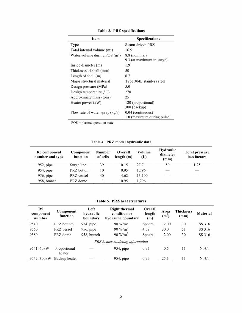
The PRZ specifications used in the modeling are assumed to be the same as those of the FW/BLK PHTS, taken from the design basis document,4 and are given in Table 3.
The PRZ is modeled by PIPE components 952, 954, 956, and 958 in accordance with RELAP5 nomenclature. The hydraulic characteristics are given in Table 4, and the line connecting the PRZ to the primary loop (surge line) is part of the model.
The hydraulic response of the PRZ to pressure transients is affected by the thermal inertia of the PRZ metal walls. To account for that fact, the walls are modeled as heat-conducting structures. Their description is summarized in Table 5.
To control system pressure, two heaters are installed in the PRZ: a proportional heater and a backup heater. In terms of modeling, the heaters represent heat-generating structures and are modeled with the same RELAP5 component as the PRZ metal walls. Table 5 lists the information for the PRZ heaters. The design document4 does not provide information beyond that in Table 5.
5
Table 3. PRZ specifications
Item Specifications Type Steam-driven PRZ Total internal volume (m3) 16.5 Water volume during POS (m3) 8.8 (nominal)
9.3 (at maximum in-surge) Inside diameter (m) 1.9 Thickness of shell (mm) 50 Length of shell (m) 6.7 Major structural material Type 304L stainless steel Design pressure (MPa) 5.0 Design temperature (°C) 270 Approximate mass (tons) 25 Heater power (kW) 120 (proportional)
300 (backup) Flow rate of water spray (kg/s) 0.04 (continuous)
1.0 (maximum during pulse) POS = plasma operation state
Table 4. PRZ model hydraulic data
R5 component number and type
Component function
Number of cells
Overall length (m)
Volume (L)
Hydraulic diameter
(mm)
Total pressure loss factors
952, pipe Surge line 39 10.15 27.7 59 1.25 954, pipe PRZ bottom 10 0.95 1,796 — — 956, pipe PRZ vessel 40 4.62 13,100 — — 958, branch PRZ dome 1 0.95 1,796 — —
Table 5. PRZ heat structures
R5 component
number
Component function
Left hydraulic boundary
Right thermal condition or
hydraulic boundary
Overall length
(m)
Area (m2)
Thickness (mm) Material
9540 PRZ bottom 954, pipe 90 W/m2 Sphere 2.00 30 SS 316 9560 PRZ vessel 956, pipe 90 W/m2 4.58 30.0 51 SS 316 9580 PRZ dome 958, branch 90 W/m2 Sphere 2.00 30 SS 316
PRZ heater modeling information
9541, 60kW Proportional heater
— 954, pipe 0.95 0.5 11 Ni-Cr
9542, 300kW Backup heater — 954, pipe 0.95 25.1 11 Ni-Cr

6
2.2 MAIN CIRCULATION PUMP
No pump type has been selected at this time, so the real pump head and torque curves are not known. For that reason the pump characteristics of a Westinghouse pump built into RELAP5 are used. The pump-rated parameters are taken from Ref. 4, and together with the RELAP5 model values are summarized in Table 6.
Table 6. Main pump characteristics and model values
Parameter type Design values Parameters in the model
R5 model values (component 934)
Maximum flow rate 71 m3/min Rated flow rate 1.179 m3/s Maximum water head 215 m Rated water head 182.2 m Shaft power 3,660 kW Rated torque 19,015 N-m Revolution speed 1,450 rpm Revolution speed 151.8 rad/s Required NPSH 22 m — — Available NPSH 113 m — — Major structural material Type 304L stainless
steel — —
Design pressure 5.0 MPa Moment of inertia
420 kg-m2
Design temperature 270°C Rated density 958 kg/m3 Outline dimensions 3.5 × 6.2 m Pump water
volume 100.5 L
Approximate mass 40 tons — — NPSH = net positive suction head
2.3 CONTROL VALVES
The control valves regulate the temperature of coolant supplied to the divertor cassettes. The currently adopted scheme for temperature control, keeping in mind that the power pulses, is a steady cold leg temperature of 100°C both during the pulse and while the pulse is off (a dwell period of zero fusion power) and a constant coolant flow rate. This control is achieved by throttling the flow through the HX using a control valve. To keep the flow rate to the divertor cassettes constant, some of the coolant must bypass the HX. The bypass leg around the HX incorporates a bypass control valve.
The control and bypass valves in Fig. 4 are the same type of valves. The control is applied to only the control valve in the main line, while the bypass mirrors (operates oppositely) the control valve (i.e., when the control valve opens, the bypass valve closes to the same extent). The valve specifications are listed in Table 7.
The VALVE component in the RELAP5 code is used to model the control and bypass valves (components 925 and 921). Because no specific valve type has been selected for the design, no information is available with which to program the function of valve loss coefficient (Cv) versus either stem position or valve area. For now, a linear function is assumed.
Besides these two valves, a small control valve is present in the model (component 963, Table 2). It is programmed to work in very low power regimes when a temperature control might be required. In the plasma operation state (POS), this valve is open practically all of the time.
An important topic related to the valve operation is the logic used to provide temperature control. It is illustrated in Fig. 4. Only the lower branch of the scheme, which is associated with the main HX control valve, is discussed here. The top branch controls the small valve in a similar manner.

7
Fig. 4. Temperature control and valve operation.
Table 7. Main control valve specifications
Item Specification Type Cage guided Valve size ND 550a Flow rate characteristic Equal percentage Rangeability Approximately 50 Rated Cv value 3600 Flow rate during POS (kg/s) 1063 (HX line), 64 (bypass) Operating pressure (MPa) 1.5 (HX line), 1.48 (bypass) Major structural material Type 304L stainless steel Design pressure (MPa) 5.0 Design temperature (°C) 270 Outline dimensions (m) Face to face: 1.4, total height: 3.3 Approximate mass (kg) 2700
aND 550 piping was originally specified in DDD 26. This piping size has subsequently been revised to ND 450, which is used in the RELAP model.
From left to right in Fig. 4, the cold leg temperature reading is compared against a temperature target
setpoint (100°C) using a proportional/integral controller, and an error is produced. After introducing a dead band of 5% and scaling down the value within the range of 0–1 in component 54, the resulting signal is compared to the valve’s current position. An error signal of valve position is generated that triggers an impulse to either open or close the valve if the error is larger (positive or negative) than 1%. This impulse is scaled to give a valve opening time of 27 s with a constant rate (0.037/s). It is continuously integrated, and the resulting function is the valve opening area.
2.4 HEAT EXCHANGER
The HX model is based on a design performed specifically for FW/BLK analysis.5 As noted earlier, the divertor and the FW/BLK cooling loops are assumed to be very similar. The old design considered an

8
HX with primary coolant on the shell side, while in the present design, the primary side is in the tube bundle. A summary of the design is shown in Fig. 5.
The HX is horizontal with a U-tube bundle and a single flow pass on the secondary side. The tube bundle is modeled with four components, two of them representing the tubes and the other two the inlet/outlet chambers. The hydraulic information for those components is given in Table 8.
The design does not include the inlet and outlet cavity sizing, and an estimate of their flow area is made here based on the shell diameter (2.116 m, Fig. 4), yielding a value of 1.758 m2 per cavity. The length of the cavity is assumed to be 0.5 m.
The heat transfer to the secondary side is modeled as a constant boundary condition (heat transfer coefficient) calculated in Ref. 5. Because RELAP5 does not allow the use of a control variable for defining the sink temperature, a pipe component is used to calculate the shell-side temperature. The information for this component is summarized in Table 9.
Fig. 5. HX design.
Table 8. HX primary-side components
R5 component number and
type
Component function
Number of cells
Overall length
(m)
Volume (m3)
Hydraulic diameter
(mm)
Total pressure loss factors
992(4), pipe Bundle 8 8.0 3.84 15.748 0.05 990(6), branch Cavities 1 0.5 0.879 — 2.49

9
Table 9. HX shell-side hydraulic parameters
R5 component number and
type
Component function
Number of cells
Volume (m3)
Diameter (mm)
Flow rate (kg/s)
In/out temperature
(°C) 992(4), pipe Shell 8 16.88 2116 916 25/90
The volume of the shell side is calculated by subtracting the volume of the tube bundle from the
overall shell volume. The baffles are not taken into account. The volume is calculated as follows:
Vshell = π × (2.116)2/4 × 8 – π × (0.01905)2/4 × 8 × 4936 = 16.88 m3 . The flow rate on the secondary side is calculated based on the total power and the temperature
increase as follows:
Flow rate = 202,000 / {4.2 × (90–25)} = 740 kg/s ,
where the power is assumed to be 202 MW, and the water-specific heat capacity is 4.2 kW/kg-°C. Thermally, the HX is modeled by two heat structures corresponding to the two sides of the U-tube
bundle and taking into account the real tube size. The information for thermal modeling is given in Table 10. The data are taken from Fig. 4, where the number of tubes should be interpreted as the number of holes in the tube sheet, making the actual number of U tubes 2468.
To design and size the HX, a fouling factor is applied on the secondary-side tubes to adjust between the clean and the real heat transfer coefficients. However, in development of the RELAP model, no fouling factor was applied.
Table 10. HX thermal modeling data
R5 component
number
Component function
Left thermal
condition
Right HTC (kW/m2 °C)
Overall length
(m)
Area, (m2)
Thickness (mm) Material
9921(41) U tube 992(4), pipe 4.95 8 1181.6 1.651 SS 316 HTC = heat transfer coefficient
3. PIPES AT ELEVATION OF 19.45 M
The pipes at an elevation of 19.45 m are used to interconnect the main equipment located there. They can be divided in two groups based on the coolant temperature they carry: cold and hot pipes (or legs).
3.1 COLD LEG
The cold leg is defined as a section of the piping between the main pump and the circular distribution header. A computer-aided design image of the cold leg together with the surge line to the PRZ is given in Fig. 6.

10
Fig. 6. Cold leg topology.
The cold leg is modeled with one single component. The basic information is summarized in Table 11
and shown in Figs. 6 and 7. The two valves (check and isolation) seen in Fig. 5 are represented as local loss factors with values of 1.2 and 0.2, respectively. The pipe size is taken from the previously developed model for the FATHOM code.6
Table 11. Cold leg from pump exit to circular headers
Pipe number
R5 component
number and type
Diameter (mm)
Number of cells
Total length (mm)
Volume (m3)
Hydraulic diameter
(mm)
Total pressure
loss factor
Number of pipes
Number of elbows
Number of valves Orientation
23 940, pipe 450 37 935 0.141009 438.2 5.04 1 1 control H 24 940, pipe 450 37 200 0.030162 438.2 1.6 1 1 check H 25 940, pipe 450 37 1,038 0.030162 438.2 0.149 1 1 H 26 940, pipe 450 37 9,505 1.180704 438.2 0.298 1 2 H 27 940, pipe 450 37 7,761 0.917688 438.2 0.298 1 2 H 63 940, pipe 450 37 6,211 0.68393 438.2 0.298 1 2 V 64 940, pipe 450 37 8,620 1.047235 438.2 0.298 1 2 H 65 940, pipe 450 37 6,701 0.757828 438.2 0.298 1 2 H 66 940, pipe 450 37 5,428 0.565845 438.2 0.298 1 2 H 67 940, pipe 450 37 22,219 3.012763 438.2 0.298 1 2 V 72 940, pipe 450 37 950 0.143271 438.2 0 1 0 H 73 940, pipe 450 37 3,741 0.140707 438.2 0.298 1 2 H 74 940, pipe 450 37 1,069 0.056404 438.2 0.149 1 1 V
Total 74,378 8.707709 9.322 18 H = horizontal V = vertical
11
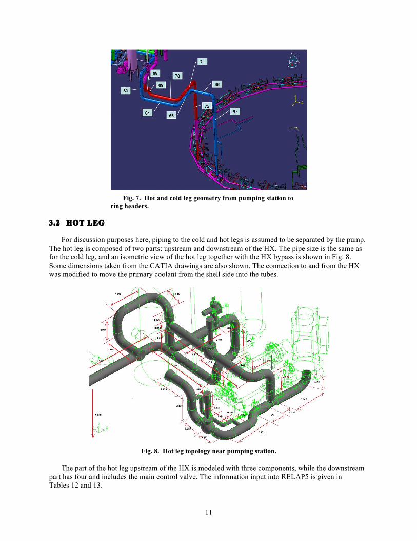
Fig. 7. Hot and cold leg geometry from pumping station to
ring headers.
3.2 HOT LEG
For discussion purposes here, piping to the cold and hot legs is assumed to be separated by the pump. The hot leg is composed of two parts: upstream and downstream of the HX. The pipe size is the same as for the cold leg, and an isometric view of the hot leg together with the HX bypass is shown in Fig. 8. Some dimensions taken from the CATIA drawings are also shown. The connection to and from the HX was modified to move the primary coolant from the shell side into the tubes.
Fig. 8. Hot leg topology near pumping station.
The part of the hot leg upstream of the HX is modeled with three components, while the downstream
part has four and includes the main control valve. The information input into RELAP5 is given in Tables 12 and 13.

12
Table 12. Hot leg from circular headers to HX bypass
Pipe number
R5 component
number and type
Diameter (mm)
Number of cells
Total length (mm)
Volume (m3)
Hydraulic diameter
(mm)
Total pressure
loss factor
Number of pipes
Number of
elbows
Number of valves Orientation
1 908, pipe 450 26 3,637 0.295741 438.2 0.298 1 2 V 2 908, pipe 450 26 1,338 0.075406 438.2 0.149 1 1 H 3 908, pipe 450 26 3,725 0.435393 438.2 5.189 1 1 1 control H 4 908, pipe 450 26 2,030 0.179767 438.2 0.149 1 1 V
68 908, pipe 450 26 1,980 0.045847 438.2 0.298 1 2 H 69 908, pipe 450 26 1,823 0.022169 438.2 0.298 1 2 V 70 908, pipe 450 26 6,859 0.781656 438.2 0.298 1 2 H 71 908, pipe 450 26 8,520 1.032154 438.2 0.298 1 2 H 72 908, pipe 450 26 22,187 3.116219 438.2 0.298 1 2 V 76 908, pipe 450 26 2,037 0.09109 438.2 0.298 1 2 H 77 908, pipe 450 26 1,279 0.080232 438.2 0.149 1 1 V
Total 55,415 6.155675 7.722 18 H = horizontal V = vertical
Table 13. Hot leg summary data for RELAP5 input
R5 component
number and type
Component function
Standard size
Number of cells
Overall length
(m)
Volume (m3)
Hydraulic diameter
(mm)
Total pressure
loss factors
Upstream of HX
916, branch To bypass — 1 0.838 0.123 431.8 — 910, pipe HX inlet — 8 10.4 1.52 431.8 1.0
Downstream of HX
924, pipe HX outlet — 5 6.2 0.91 431.8 0.5 909, pipe Pump leg 1 — 4 6.8 1.0 431.8 0.5 932, branch From bypass — 1 0.838 0.123 431.8 — 928, pipe Pump leg 2 — 3 3.8 0.56 431.8 0.25
3.3 BYPASS
The two PHTS bypasses near the HX modeled are the main HX bypass, which contains the bypass valve, and the small bypass around the main control valve (Fig. 8). The small bypass valve is used to trim the flow under low-flow conditions but does not have a real control function for the analysis performed here. Each bypass has two legs—one upstream and one downstream of the corresponding valve. The input data for these legs are presented in Table 14 and shown in Fig. 8.

13
Table 14. Bypass input information
R5 component number and
type
Component function
Standard size
Number of cells
Overall length
(m)
Volume (m3)
Hydraulic diameter
(mm)
Total pressure loss
factors
Main bypass legs
920, pipe To valve — 2 4.8 0.51 431.8 — 922, pipe From valve — 5 8.7 1.27 431.8 0.5
Small bypass legs
962, pipe To valve — 4 2.9 0.048 146.3 0.5 964, pipe From valve — 4 3.1 0.052 146.3 0.5
4. CIRCULAR DISTRIBUTOR AND COLLECTOR
These two components deliver and return the coolant to the multiple pipes that connect the circular header and collector to the divertor cassettes. They are shown in Fig. 9, which illustrates their positions.
There is one distributor/collector pair. They components are circular because they deliver and return coolant to the 54 divertor cassettes located 360° around the vacuum vessel. The supply/return lines (branch piping) begin from these components and end at the divertor cassettes.
The circular headers are single pipes, located lower than the remainder of the PHTS. The connections to the hot and cold legs are in the middle of both the distributor and collector, as shown in Fig. 8. They are modeled with two identical pipes. The input information is presented in Tables 15 and 16. The cold leg distributor is the inner header, and the hot leg collector is the outer header.
Fig. 9. Circular distributor (inside) and collector (outside) belonging to the
divertor PHTS. .

14
Table 15. Circular collector RELAP5 information
Pipe number
R5 component
number
Diameter (mm)
Number of cells
Total length (mm)
Volume (m3)
Hydraulic diameter
(mm)
Total pressure
loss factor
Number of pipes
Number of elbows
Number of valves Orientation
78 906 300 70 8,866 0.626034 304.85 0.164 1 2 H 94 906 300 70 8,211 0.578225 304.85 0.164 1 2 H 95 906 300 70 8,211 0.578225 304.85 0.164 1 2 H 96 906 300 70 8,211 0.578225 304.85 0.164 1 2 H 97 906 300 70 8,211 0.578225 304.85 0.164 1 2 H 98 906 300 70 8,211 0.578225 304.85 0.164 1 2 H 99 906 300 70 8,870 0.626326 304.85 0.164 1 2 H
100 906 300 70 14,941 1.08003 304.85 0.082 1 1 H 101 906 300 70 3,206 0.223495 304.85 0.082 1 1 H 102 906 300 70 8,211 0.578225 304.85 0.164 1 2 H 103 906 300 70 8,211 0.578225 304.85 0.164 1 2 H 104 906 300 70 8,211 0.578225 304.85 0.164 1 2 H 105 906 300 70 8,211 0.578225 304.85 0.164 1 2 H 106 906 300 70 8,223 0.579101 304.85 0.164 1 2 H 107 906 300 70 8,870 0.626326 304.85 0.164 1 2 H 108 906 300 70 14,546 1.040616 304.85 0.164 1 2 H
Total 141,421 10.00596 2.46 30 H = horizontal
Table 16. Circular distributor RELAP5 information
Pipe number
R5 component
number
Diameter (mm)
Number of cells
Total length (mm)
Volume (m3)
Hydraulic diameter
(mm)
Total pressure
loss factor
Number of pipes
Number of elbows
Number of valves Orientation
75 942 300 60 7,971 0.560708 304.85 0.082 1 1 H 79 942 300 60 7,497 0.526111 304.85 0.164 1 2 H 80 942 300 60 7,506 0.526768 304.85 0.164 1 2 H 81 942 300 60 7,497 0.526111 304.85 0.164 1 2 H 82 942 300 60 7,514 0.527351 304.85 0.164 1 2 H 83 942 300 60 7,506 0.526768 304.85 0.164 1 2 H 84 942 300 60 7,975 0.561 304.85 0.164 1 2 H 85 942 300 60 13,688 0.977991 304.85 0.164 1 2 H 86 942 300 60 2,820 0.195321 304.85 0.082 1 1 H 87 942 300 60 6,235 0.444581 304.85 0.082 1 1 H 88 942 300 60 7,506 0.526768 304.85 0.164 1 2 H 89 942 300 60 7,506 0.526768 304.85 0.164 1 2 H 90 942 300 60 7,497 0.526111 304.85 0.164 1 2 H 91 942 300 60 7,497 0.526111 304.85 0.164 1 2 H 92 942 300 60 7,975 0.561 304.85 0.164 1 2 H 93 942 300 60 13,688 0.977991 304.85 0.164 1 2 H
Total 127,878 9.017454 2.378 29 H = horizontal

15
5. BRANCH PIPING FROM DISTRIBUTOR/COLLECTOR TO DIVERTOR CASSETTES
The branch lines deliver and return coolant from the circular headers to the divertor cassettes. The return and delivery branches each have 18 pipes running in parallel, with each of those serving three divertor cassettes. They are further subdivided into three parts: branch piping near the headers (collector and distributor), vertical branch piping, and branch piping near the divertor. The models of these three parts differ slightly and are described below.
There are 18 supply and 18 return branch pipes, each positioned ~20° apart, supplying the divertor cassettes.
5.1 HOT AND COLD LEG BRANCH PIPING NEAR COLLECTOR AND DISTRIBUTOR
This part begins from the circular headers. There are 18 (ND 150) branch lines attached to each of the circular headers. Each acts as a supply or return line from three divertor cassettes. Each ND 150 line attached to the header splits into three ND 65 branch lines that act as supply or return coolant piping for individual divertor cassettes. The splits to ND 65 piping are shown in Fig. 10.
In the modeling of this section, some degree of approximation is used because, as seen in the figures, each line has a different length and geometric configuration.
In the model, the 18 ND 150 branch piping is lumped into three separate hot and cold leg branches, and the 54 (18 × 3) ND 65 lines are also lumped into three separate lines. In the model (Fig. 10), branches near the headers are modeled with components 200–205.
All of these components are assumed to be identical, and the relevant information is given in Tables 17, 18, and 19.
Fig. 10. Branch piping near circular headers.

16

17
Table 17. Divertor branch piping near circular headers
Pipe number
R5 component
number
Diameter (mm)
Number of cells
Total length (mm)
Volume (m3)
Hydraulic diameter
(mm)
Total pressure
loss factor
Number of pipes
Number of elbows
Number of valves Orientation
109 200–205 150 6 359 0.011969 154.07 0.18 6 1 H 110 200–205 150 6 1,068 0.063089 154.07 6.25 6 2 1 control H 111 200–205 150 6 1,068 0.063089 154.07 0.36 6 2 H 112 200–205 150 6 2,107 0.179313 154.07 0.36 6 2 V 113 200–205 150 6 1,764 0.140944 154.07 0.36 6 2 H 114 200–205 150 6 2,803 0.285356 154.07 0.18 6 1 H
Total 9,169 0.743761 7.69 10 H = horizontal V = vertical
Table 18. Divertor branch piping, vertical
Pipe number
R5 component
number
Diameter (mm)
Number of cells
Total length (mm)
Volume (m3)
Hydraulic diameter
(mm)
Total pressure
loss factor
Number of pipes
Number of elbows
Number of valves Orientation
125 210–215 65 13 683 0.032078 62.71 0.217 18 1 H 126 210–215 65 13 1,222 0.056151 62.71 0.434 18 2 H 127 210–215 65 13 447 0.013065 62.71 0.434 18 2 H 128 210–215 65 13 1,321 0.061655 62.71 0.434 18 2 H 129 210–215 65 13 721 0.028298 62.71 0.434 18 2 H 169 210–215 65 13 825 0.03408 62.71 0.434 18 2 V 170 210–215 65 13 1,537 0.070995 62.71 0.434 18 2 H 171 210–215 65 13 4,428 0.229052 62.71 0.434 18 2 V 172 210–215 65 13 1,277 0.053872 62.71 0.434 18 2 H 173 210–215 65 13 922 0.034135 62.71 0.434 18 2 V 174 210–215 65 13 3,159 0.158501 62.71 0.434 18 2 H 175 210–215 65 13 1,805 0.091787 62.71 0.217 18 1 V
Total 18,347 0.863669 4.774 22 H = horizontal V = vertical
Table 19. Divertor branch piping near divertor
Pipe number
R5 component
number
Diameter (mm)
Number of cells
Total length (mm)
Volume (m3)
Hydraulic diameter
(mm)
Total pressure
loss factor
Number of pipes
Number of elbows
Number of
valves Orientation
176 220–225 65 7 9,931 0.530821 62.71 0.217 18 1 H 177 220–225 65 7 1,213 0.024462 62.71 0.434 18 2 H 178 220–225 65 7 2,041 0.087896 62.71 0.434 18 2 H 179 220–225 65 7 2,340 0.126201 62.71 0 18 H
Total 15,525 0.76938 1.085 5 H = horizontal

18
5.2 VERTICAL BRANCH PIPING
In this section the ND 65 lines split from the ND 150 lines and run parallel and upward from the circular headers. These lines have an elevation change of approximately 20 m. Parts of the CATIA drawing remain unfinished, as indicated by breaks in the piping drawings. The connecting piping necessary to fill these breaks has been approximated to complete the RELAP model. The pipe configuration is shown in Fig. 11.
Fig. 11. Vertical branch piping.
The supply and the return lines run in parallel, making the number of pipes in the vertical section
equal to 54. In the model, the lines are lumped into one component per set of branch pipes, and the data are presented in Table 18.
Because the length of branch piping varies depending on the specific location around the ring headers, the RELAP model includes representative lengths as opposed to specific ones.
5.3 BRANCH PIPING NEAR DIVERTOR
The horizontal branch piping runs through the cryostat and lower vacuum vessel ports. It is a continuation of the vertical branches and has the same pipe number and size. The piping connects to the divertor cassettes. A set of horizontal branch piping is shown in Fig. 12, and the model data are given in Table 19.
Because the length of branch piping varies depending on the specific location around the ring headers, the RELAP model includes representative lengths as opposed to specific ones.

19
Fig. 12. Horizontal branch piping to/from divertor.
6. DIVERTOR MODEL, POWER
In this RELAP model, the divertor is assumed to have no thermal inertia and to act only as an energy input to the divertor PHTS coolant. The normalized power pulse is assumed to be that shown in Fig. 13.
Fig. 13. Divertor power pulses.

20
7. SIMULATION OF PLASMA OPERATION STATE
The RELAP model is used to simulate divertor PHTS operation during the basic power mode (e.g., Inductive Plasma Operation)—POS. The modeled state is characterized by repetitive power pulses with time intervals of 30 min (1800 s). The process is transient but with steady cycles of the system parameters. To reach those steady cycles, several pulses are simulated.
The simulation shows the general behavior of the time-dependent divertor PHTS thermal parameters during POS. Maintaining the coolant temperature and flow delivered to the divertor cassette depends on the control logic used. Constant divertor cassette inlet temperature and constant flow are specified by the divertor designers at this stage of the PHTS design.
The results presented here should be considered preliminary and therefore only approximate. They reflect a design stage with many unknowns, such as equipment operating characteristics, operation logic, etc. The model developed provides a framework to build upon. As soon as information becomes available regarding the characteristics of specific equipment selected by the architect engineer, the model can be updated.
7.1 PULSED POWER MODE
The pulsed power during POS is assumed to be applied to the divertor coolant with exactly the same temporal shape as the plasma pulse. It is assumed that the divertor structure does not affect the energy deposition into the divertor PHTS coolant, and there is no thermal inertia associated with the divertor itself. Four power pulses are simulated and are shown in Fig. 13.
7.2 PRIMARY COOLANT TEMPERATURES
The PHTS target control parameter is the cold leg temperature, or the coolant temperature supplied to the divertor cassette. The current requirement is that divertor cassette inlet temperature be maintained at 100°C with +5/–20°C of tolerance (margin).2 Flow control is used to achieve this level by controlling the amount of coolant running through the HX. The control logic for operating the valve regulating the flow through the HX was described in Sect. 2.3.
The hot leg temperature is the temperature of coolant returning from the divertor. The hot and the cold leg temperatures are plotted in Fig. 14. The hot leg temperature follows the power change, while the cold leg temperature fluctuates based on the efficiency of the control valve system, including both the control valve operation and the control logic. The deviation is +3/–2 degrees. Because the purpose of this calculation is to qualitatively show the temperature evolution during a power pulse, no further changes to the control logic were made to improve the control of the cold leg temperature.
An alternative option for temperature control would be to maintain a constant average temperature of the PHTS. This logic would minimize the expansion of the coolant during the pulse and thus pose less of a load on the PRZ to accommodate the excess volume.
7.3 MAIN AND BYPASS FLOWS
The divertor design requirement is to maintain a constant flow though the divertor cassettes. As discussed previously, to control the temperature, part of the flow is directed through an HX. To keep the overall flow constant, an HX bypass line is used. Two valves control the flow by mirroring each other during operation. (When one opens, the other closes.) The flow rates through these two valves are shown in Fig. 15.

21
Fig. 14. Primary coolant temperatures.
Fig. 15. Mass flow rates.

22
The total flow rate is about 980 kg/s (this number needs to be verified for the final design calculation) and is kept essentially steady throughout the pulse. Small fluctuations, caused by the change of the flow resistance when the valves operate, are seen. The HX line shows the flow passing through the HX, which is the flow required to remove the heat generated in the blanket. The magnitude of that flow is a measure of the HX thermal capacity, and in this case the HX is very efficient and needs about 50% of the total flow to remove the heat. Therefore, it might be reasonable to consider a possible redesign of the HX. Another cause of this high efficiency could be that the fouling of the HX tubes is not taken into account in the present RELAP model, but it was considered in the HX design and sizing calculations. All of this is subject to further analysis and eventual model improvement.
The bypass valve in the HX bypass line operates opposite the valve controlling the flow through the HX. This mode would be appropriate if the HX train and the bypass line had the same flow resistance. In the current hydraulic design, this is not the case. An alternative to this mode would be a mode in which the HX valve controls the temperature of coolant going to the blanket, and the bypass valve controls the flow delivered.
7.4 PRESSURE AND PRESSURE DISTRIBUTION
The calculated pressure at different locations during the pulses is shown in Fig. 16. The plot also gives a picture of the pressure distribution in the system.
One specific characteristic of the divertor PHTS is the large pressure drop across the divertor cassettes, about 1.6 MPa. This feature makes the hot part of the system run at much lower pressure than the cold part. This difference raises questions regarding the appropriate location of the PRZ (hot or cold side), as is discussed in Ref. 1.
DIV = divertor
Fig. 16. Pressure at different locations.

23
The pressure difference between the divertor exit and the pump intake accounts for the losses in the
HX. With all losses and elevation changes added, the lowest pressure in the system (pump intake) is almost one-half the highest pressure. Such a large pressure drop would require high pumping power, which might result in a custom pump design.
The pulsed power causes the temperature to change and the coolant to expand and contract. The amount of primary coolant volume resulting from that change needs to be accommodated by the PRZ while maintaining pressure within the acceptable tolerance band, which is ±0.2 MPa.2
The plot in Fig. 16 clearly shows a pressure fluctuation that exceeds the required margin even though an active pressure control is used. When the pressure starts to rise during the plasma power ramp, cold coolant with a maximum flow rate of 1 kg/s is sprayed in the PRZ dome to reduce the pressure. Some sensitivity runs were made for a similar FW/BLK1 to assess the effect of the spray actuation set points and the spray flow rate. That study found that the rising pressure trend was quite high and increasing the spray capacity most likely would not help. There are two negative consequences of spraying in the PRZ at every pulse: (1) the primary inventory is unbalanced, and (2) the coolant in the PRZ is cooled.
Two questions arise from this finding: (1) should an active pressure suppression control be used at all, or (2) should the PRZ size be increased to maintain the pressure within the required limits? Another approach might be to increase the allowed pressure tolerance.
Similarly, the negative pressure spike is also not accommodated without an active control. The heaters operate to compensate for the effect of volume shrinkage. Their time response is slow because of the thermal inertia of the system. Additionally, heaters are located in the bottom of the PRZ where the cold coolant ingress from the loop decreases the local temperature, which is at saturation. This process postpones the time of vapor generation inception after the heater is turned on, further delaying the impact of heater operation on the primary pressure.
The large difference in the pressure spike at the divertor inlet and in the PRZ (Fig. 15) was found to be caused by the hydraulic resistance of the surge line. The current surge line diameter is 59 mm, much smaller than the main coolant pipe (482 mm). Unless limited by other restrictions (space, thermal stress, etc.), it might be appropriate to increase the size of the surge line to minimize the pressure drop during in-surge events. If that is not possible, then the pressure used to control the spray and the safety valves has to be taken at the high-pressure side of the blanket (see Section 9 of Ref. 1).
7.5 PRIMARY COOLANT INVENTORY
The primary coolant inventory is maintained by the CVCS. The measure of primary inventory is the level in the PRZ. A permanent spray of 0.4 kg/s is used in the PRZ to keep the PRZ chemistry equal to that in the remainder of the PHTS. The number is a legacy number from the 2004 design and should be adjusted if necessary. This spray flow rate is matched by the same letdown flow rate of the CVCS. Additional spray is added above the constant value to maintain system pressure during the plasma pulse as the liquid inventory expands into the PRZ.
The PRZ level as a percentage of the total PRZ height is plotted in Fig. 17. The span of the level during the power pulse is less than 20%, which is quite acceptable. The level shown in Fig. 17 is rising slightly because of the spray operation used to mitigate the pressure spike (i.e., spray flow above the 0.4 kg/s value). The model does not adjust the CVCS flow to accommodate the extra liquid injected by the transient spray. The red line in Fig. 17 shows the time-dependent spray normalized by the continuous spray flow rate.
No clear information exists on what PRZ level should be maintained by the CVCS during POS. Sources suggest the level should be a function of the primary average temperature. This approach does not seem appropriate because both the level and the average temperature change during a power pulse and therefore most likely cannot be followed by the CVCS operation. Some alternative approach is necessary.

24
Fig. 17. Level in the PRZ.
8. CONCLUSIONS AND RECOMMENDATIONS
The RELAP5 model of the divertor PHTS was run to simulate several consecutive power pulses during the POS mode of ITER operation. The model reflects the current design, which is not final. To that extent the conclusions here are not definite and will require revision after changes in the equipment characteristics or functions are made. The current model summary is as follows:
• The divertor PHTS loop is simulated. • The system is modeled up to the divertor cassettes. The divertor cassettes themselves are not
modeled in detail but are represented as lumped components. • The power of the divertor component is assumed to be a flat-topped pulse with a rise time of 30 s
and a ramp down of 60 s, implying no divertor thermal inertia. • POS mode is simulated, and four consecutive power pulses are computed. A power control
component was developed in the RELAP5 model to periodically repeat the power pulses. • The system target parameter is the coolant temperature supplied to the divertor. Some control
logic is applied to maintain that temperature, which was taken from the input data described in Ref. 1.
• The pulsed power causes the system parameters to fluctuate. Both the temperature and in particular the pressure fluctuations are larger than the limits established in the design description document.7
Based on these preliminary analyses, the following systems and components need to be revised as the
design progresses:
• The divertor module is presently represented as a lumped component, and the power input directly follows plasma operation. The representative divertor cassette module thermal data need to be

25
updated to provide a more realistic divertor thermal response if its thermal inertia turns out to be large enough to affect the heat transfer behavior.
• The control and bypass valve characteristics and control logic need to be modified. • For the main pump data, the RELAP5 pump data that have been used in these calculations need to be
replaced by real pump data. • The current design of the branch pipes will most likely change. The vertical section of the branch
piping has some uncertainty in the layout that needs to be clarified. • The final HX design is still not available. Once completed, the design will have to be implemented in
the model. • Piping heat structures were not included in this model. For problems in which piping thermal inertia
might be important, these need to be added to the model.
9. REFERENCES
1. E. Popov, G. L. Yoder, and S. H. Kim, RELAP5 Model of the First Wall/Blanket Primary Heat Transfer System, US ITER 12101-TD0001-R00, 2010.
2. W. Curd, System Requirement Document (SRD), SRD-26-PH, -CV, -DR, -DY (TCWS) FROM DOORS, IDM UID 2823A2, 2009.
3. Applied Programming Technology, Inc., Symbolic Nuclear Analysis Package (SNAP), 2007. 4. A. Nishikawa, Design Basis on Primary First Wall and Blanket PHTS for ITER-FEAT, N 26 MD 30
99-11-17 W 0.3, 2000. 5. G. Yoder, personal communication, calculation results using Shell and Tube Heat Exchanger Design,
2009. 6. S. Kim, J. Liem and G. Yoder, Jr., Pipe Flow Analysis and System Modeling of the Four Primary
Heat Transfer Systems of International Thermonuclear Experimental Reactor, US ITER 12100-TD0003-R00, Sept. 2007.
7. ITER, Design Description Document, Cooling Water System (DDD 26), N 26 DDD 46 R0.2, 2004.

US ITER 12102-TD0002-R00
INTERNAL DISTRIBUTION
1. J. B. Berry 5. E. Popov 2. J. J. Carbajo 6. K. L. Wilcher 3. J. J. Ferrada 7. G. L. Yoder, Jr 4. S. H. Kim 8. File-USIPO DCC-RC
EXTERNAL DISTRIBUTION
9. W. Curd, ITER International Office, St. Paul Lez Durance Cedex, France 13607 10. G. Dell’Orco, ITER International Office, St. Paul Lez Durance Cedex, France 13607