reliability and state machines in an advanced network …newbold/thesis/thesis.pdf · reliability...
TRANSCRIPT

RELIABILITY AND STATE MACHINES IN AN
ADVANCED NETWORK TESTBED
by
Mac G. Newbold
A thesis submitted to the faculty ofThe University of Utah
in partial fulfillment of the requirements for the degree of
Master of Science
in
Computer Science
School of Computing
The University of Utah
December 2004

Copyright c© Mac G. Newbold 2004
All Rights Reserved

THE UNIVERSITY OF UTAH GRADUATE SCHOOL
SUPERVISORY COMMITTEE APPROVAL
of a thesis submitted by
Mac G. Newbold
This thesis has been read by each member of the following supervisory committee and bymajority vote has been found to be satisfactory.
Chair: Jay Lepreau
John Carter
Matthew Flatt
Konrad Slind
THE UNIVERSITY OF UTAH GRADUATE SCHOOL
FINAL READING APPROVAL
To the Graduate Council of the University of Utah:
I have read the thesis of Mac G. Newbold in its final form and havefound that (1) its format, citations, and bibliographic style are consistent and acceptable;(2) its illustrative materials including figures, tables, and charts are in place; and (3) thefinal manuscript is satisfactory to the Supervisory Committee and is ready for submissionto The Graduate School.
Date Jay LepreauChair: Supervisory Committee
Approved for the Major Department
Chris R. JohnsonChair/Director
Approved for the Graduate Council
David S. ChapmanDean of The Graduate School

ABSTRACT
Complex distributed systems have many components that fail from time to time,
adversely affecting the system’s overall reliability. Our advanced network testbed,
Emulab, also known as Netbed, is a complex time- and space-shared distributed
system, composed of thousands of hardware and software components. Early versions
of the Emulab system had reliability problems, could support experiments of only
limited size, and were inefficient in resource use.
Our thesis is that enhancing Emulab with better monitoring and control through
a flexible framework based on state machines improves the reliability, scalability,
performance, efficiency, and generality of the system. Reliability is key, because of its
effect on scalability, performance and efficiency. Any solution used to address these
issues must be general across a variety of workloads, and portable across different
software and hardware configurations.
Our results show improvement through faster error detection and recovery, better
monitoring of testbed nodes, and prevention of race conditions. The state machine
framework has also contributed to Emulab’s generality and portability by expanding
the accepted workload, providing graceful degradation for less capable node configu-
rations, and making it easier to add new node types to the testbed.

For my family, past, present, and future

CONTENTS
ABSTRACT . . . . . . . . . . . . . . . . . . . . . . . . . . . . . . . . . . . . . . . . . . . . . . . . . . iv
LIST OF FIGURES . . . . . . . . . . . . . . . . . . . . . . . . . . . . . . . . . . . . . . . . . . . . viii
ACKNOWLEDGMENTS . . . . . . . . . . . . . . . . . . . . . . . . . . . . . . . . . . . . . . . ix
CHAPTERS
1. INTRODUCTION . . . . . . . . . . . . . . . . . . . . . . . . . . . . . . . . . . . . . . . . . 1
2. EMULAB ARCHITECTURE . . . . . . . . . . . . . . . . . . . . . . . . . . . . . . . 6
2.1 Software Architecture . . . . . . . . . . . . . . . . . . . . . . . . . . . . . . . . . . . . . 62.2 Hardware Components . . . . . . . . . . . . . . . . . . . . . . . . . . . . . . . . . . . . . 92.3 Central Database . . . . . . . . . . . . . . . . . . . . . . . . . . . . . . . . . . . . . . . . . 112.4 User Interfaces . . . . . . . . . . . . . . . . . . . . . . . . . . . . . . . . . . . . . . . . . . . 12
2.4.1 Web Interface . . . . . . . . . . . . . . . . . . . . . . . . . . . . . . . . . . . . . . . 132.4.2 ns Scripts . . . . . . . . . . . . . . . . . . . . . . . . . . . . . . . . . . . . . . . . . . . 132.4.3 Graphical User Interface (GUI) . . . . . . . . . . . . . . . . . . . . . . . . . . 132.4.4 Command Line . . . . . . . . . . . . . . . . . . . . . . . . . . . . . . . . . . . . . . 142.4.5 Programmatic Interfaces (APIs) . . . . . . . . . . . . . . . . . . . . . . . . . 14
2.5 Access Control . . . . . . . . . . . . . . . . . . . . . . . . . . . . . . . . . . . . . . . . . . . 152.6 Link Configuration and Control . . . . . . . . . . . . . . . . . . . . . . . . . . . . . . 16
3. ISSUES, CHALLENGES, AND AN APPROACH . . . . . . . . . . . . . 18
3.1 Reliability . . . . . . . . . . . . . . . . . . . . . . . . . . . . . . . . . . . . . . . . . . . . . . 183.2 Scalability . . . . . . . . . . . . . . . . . . . . . . . . . . . . . . . . . . . . . . . . . . . . . . 203.3 Performance and Efficiency . . . . . . . . . . . . . . . . . . . . . . . . . . . . . . . . . 203.4 Generality and Portability . . . . . . . . . . . . . . . . . . . . . . . . . . . . . . . . . . 213.5 State Machines in Emulab . . . . . . . . . . . . . . . . . . . . . . . . . . . . . . . . . . 22
3.5.1 Why State Machines? . . . . . . . . . . . . . . . . . . . . . . . . . . . . . . . . . 24
4. STATE MACHINES IN EMULAB . . . . . . . . . . . . . . . . . . . . . . . . . . . 25
4.1 State Machine Representation . . . . . . . . . . . . . . . . . . . . . . . . . . . . . . . 254.2 How State Machines Interact . . . . . . . . . . . . . . . . . . . . . . . . . . . . . . . . 29
4.2.1 Direct Interaction . . . . . . . . . . . . . . . . . . . . . . . . . . . . . . . . . . . . 304.2.2 Indirect Interaction . . . . . . . . . . . . . . . . . . . . . . . . . . . . . . . . . . . 30
4.3 Models of State Machine Control . . . . . . . . . . . . . . . . . . . . . . . . . . . . . 314.3.1 Centralized . . . . . . . . . . . . . . . . . . . . . . . . . . . . . . . . . . . . . . . . . 324.3.2 Distributed . . . . . . . . . . . . . . . . . . . . . . . . . . . . . . . . . . . . . . . . . 33

4.4 Emulab’s State Daemon . . . . . . . . . . . . . . . . . . . . . . . . . . . . . . . . . . . . 34
5. NODE CONFIGURATION PROCESS . . . . . . . . . . . . . . . . . . . . . . . 36
5.1 Node Self-Configuration . . . . . . . . . . . . . . . . . . . . . . . . . . . . . . . . . . . . 365.2 The Node Boot Process . . . . . . . . . . . . . . . . . . . . . . . . . . . . . . . . . . . . 37
5.2.1 Variations of the Node Boot Process . . . . . . . . . . . . . . . . . . . . . . 385.3 The Node Reloading Process . . . . . . . . . . . . . . . . . . . . . . . . . . . . . . . . 42
6. EXPERIMENT CONFIGURATION PROCESS . . . . . . . . . . . . . . . 45
6.1 Experiment Status State Machine . . . . . . . . . . . . . . . . . . . . . . . . . . . . 456.2 Node Allocation State Machine . . . . . . . . . . . . . . . . . . . . . . . . . . . . . . 47
7. RESULTS . . . . . . . . . . . . . . . . . . . . . . . . . . . . . . . . . . . . . . . . . . . . . . . . . 50
7.1 Arguments . . . . . . . . . . . . . . . . . . . . . . . . . . . . . . . . . . . . . . . . . . . . . . 507.2 Anecdotal . . . . . . . . . . . . . . . . . . . . . . . . . . . . . . . . . . . . . . . . . . . . . . . 52
7.2.1 Reliability/Performance: Preventing Race Conditions . . . . . . . . . 527.2.2 Generality: Graceful Handling of Custom OS Images . . . . . . . . . 537.2.3 Reliability/Scalability: Improved Timeout Mechanisms . . . . . . . 557.2.4 Generality: Adding New Node Types . . . . . . . . . . . . . . . . . . . . . 567.2.5 Reliability/Scalability/Performance: Access Control/Locking . . . 577.2.6 Reliability: Detecting Unexpected Behaviors . . . . . . . . . . . . . . . . 58
7.3 Experimental . . . . . . . . . . . . . . . . . . . . . . . . . . . . . . . . . . . . . . . . . . . . 58
8. RELATED WORK . . . . . . . . . . . . . . . . . . . . . . . . . . . . . . . . . . . . . . . . . 61
8.1 State Machines and Automata . . . . . . . . . . . . . . . . . . . . . . . . . . . . . . . 618.1.1 Timed Automata . . . . . . . . . . . . . . . . . . . . . . . . . . . . . . . . . . . . . 62
8.2 Message Sequence Charts and Scenarios . . . . . . . . . . . . . . . . . . . . . . . 628.3 Statecharts in UML . . . . . . . . . . . . . . . . . . . . . . . . . . . . . . . . . . . . . . . 628.4 Testbed Related Work . . . . . . . . . . . . . . . . . . . . . . . . . . . . . . . . . . . . . 63
9. CONCLUSIONS AND FUTURE WORK . . . . . . . . . . . . . . . . . . . . . 64
REFERENCES . . . . . . . . . . . . . . . . . . . . . . . . . . . . . . . . . . . . . . . . . . . . . . . . 67
vii

LIST OF FIGURES
1.1 State machine framework overview . . . . . . . . . . . . . . . . . . . . . . . . . . . . . 4
2.1 Emulab system architecture . . . . . . . . . . . . . . . . . . . . . . . . . . . . . . . . . . 6
2.2 Emulab software architecture . . . . . . . . . . . . . . . . . . . . . . . . . . . . . . . . . 7
2.3 Emulab hardware components . . . . . . . . . . . . . . . . . . . . . . . . . . . . . . . . 10
2.4 A link with traffic shaping . . . . . . . . . . . . . . . . . . . . . . . . . . . . . . . . . . . 17
3.1 A simple state machine, or state transition diagram. . . . . . . . . . . . . . . 23
4.1 Interactions among three state machines . . . . . . . . . . . . . . . . . . . . . . . . 26
4.2 Three state machines viewed as one larger machine . . . . . . . . . . . . . . . . 27
5.1 The typical node boot state machine . . . . . . . . . . . . . . . . . . . . . . . . . . . 37
5.2 WIDEAREA state machine . . . . . . . . . . . . . . . . . . . . . . . . . . . . . . . . . . . . . 39
5.3 MINIMAL state machine . . . . . . . . . . . . . . . . . . . . . . . . . . . . . . . . . . . . . . 40
5.4 PCVM state machine . . . . . . . . . . . . . . . . . . . . . . . . . . . . . . . . . . . . . . . . . 41
5.5 ALWAYSUP state machine . . . . . . . . . . . . . . . . . . . . . . . . . . . . . . . . . . . . . 42
5.6 The node reloading process . . . . . . . . . . . . . . . . . . . . . . . . . . . . . . . . . . 43
6.1 Experiment status state machine . . . . . . . . . . . . . . . . . . . . . . . . . . . . . . 46
6.2 Node allocation state machine . . . . . . . . . . . . . . . . . . . . . . . . . . . . . . . . 48

ACKNOWLEDGMENTS
First and foremost, I need to express my gratitude to my beautiful wife, Susan,
without whose patience and long-suffering this thesis would have never materialized.
She has lovingly tolerated many boring conversations, presentations, and thesis drafts.
My two sons, Oliver and David, while currently too young to notice much, have
likewise endured the many absences, distractions, and frustrations caused by my
studies. My wife and children constantly provide me with much-needed motivation
and support, for which I am eternally grateful. My parents, siblings, and other family
members have also been patient and supportive, and without the many things they
have taught me, I would never have made it this far.
My advisor and friend, Jay Lepreau, has patiently worked with me during my
undergraduate and graduate studies, and has given me many opportunities that have
shaped my career. I am grateful for the confidence and trust that he has placed in
me. His guidance and support has been invaluable in my research and this thesis.
I can say nothing about Emulab or my part in it without first mentioning the
team that is responsible for its success. Many faces have come and gone, and each
has made my work possible through their work on Emulab and in the Flux research
group, but there are some who stand out in my mind as being especially influential
in my life. Mike Hibler and Leigh Stoller have taught me innumerable lessons with
their expertise and patience. They are truly masters of the art they practice. I am
grateful for Robert Ricci and Kirk Webb, for their many talents and their willingness
to share them, and for their friendship. Other colleagues and friends who should be
mentioned by name are Shashi Guruprasad, Abhijeet Joglekar, Parveen Patel, Eric
Eide, Chris Alfeld and Brian White. Numerous others have contributed to Emulab,
and are remembered with gratitude.

CHAPTER 1
INTRODUCTION
Distributed systems are hard to design, develop, and test. An important tool
in evaluating a distributed system is a testbed. Our Emulab network testbed[26],
also known as Netbed, is an advanced network testbed that provides a controlled
environment through combinations of simulation, emulation, and live networks. The
testbed itself is a complex distributed system, composed of hundreds of clustered
PCs, hundreds of participating nodes on the Internet, a variety of special purpose
hardware, and thousands of virtual and simulated nodes. The system is time- and
space-shared, and provides an automated way to configure computers and network
hardware into a synthetic network environment. This synthetic environment is known
in Emulab as an experiment.
Emulab began as a testbed of 10 PCs in April 2000, and opened for public
production use with 40 PCs in October 2000. Since then, it has grown to over
180 PCs, with hundreds of nodes around the Internet, and thousands of virtual and
simulated nodes. It has been used by over 750 users in more than 150 projects
at about 75 institutions, allocating over 155,000 nodes in over 10,000 experiment
instances. Seventeen classes at 12 universities have used it for coursework. Emulab
software currently runs production testbeds at six sites, with about six more sites in
the planning or construction stages.
Emulab is a large and complex production software system. During normal
operation, the system includes about 35 daemons running on Emulab’s servers, with
12 more running on each node. About 30 of those daemons were written by our
team, and another 15 have been modified or integrated as a necessary part of the
testbed’s infrastructure. The others are standard daemons that are required for

2
proper operation. Our team’s software base is composed of over 300,000 lines of
code in about 450 programs and scripts, about 150 of which are the web scripts that
make up Emulab’s web interface. The remainder includes daemons, programs, and
scripts that run on Emulab servers, nodes, or on a user’s desktop machine.
As we gained experience with Emulab, and as it continued to grow in size, it
became evident that it had reliability problems that needed to be dealt with. Many
things can cause failures in a large system like Emulab, including any combination of
hardware and software errors, user errors, and interference by users at inopportune
moments. In addition to reliability issues, failures limit the maximum size of an ex-
periment, degrade performance, and cause testbed resources to be used less efficiently
with lower throughput.
Reliability, scalability, performance, and efficiency are all closely related, and
directly affect throughput and usability of the testbed. Failure rates in part determine
the maximum scale that can be achieved on the system, as well as the speed at which
the system can complete its tasks. Decreased reliability also adversely impacts effi-
ciency, causing resources that would normally be utilized effectively, to be unavailable
for a longer time than necessary.
While generality and portability are not directly related to reliability, they con-
strain our solution to the problems in Emulab. One aspect of generality is workload
generality – the range of workloads for which the testbed is appropriate. Rather
than affecting performance in degree, generality has an absolute effect, and often
determines whether a task is possible or impossible, rather than simply being slower
or faster. Any software that is required to run on Emulab test nodes must be easily
portable to a variety of operating systems and hardware architectures, including
highly-constrained embedded environments. A testbed cannot compensate for a lack
of generality by improving in any of the other aspects.
Our thesis is that enhancing Emulab with better monitoring and control through
a flexible framework based on state machines improves the reliability, scalability,
performance, efficiency, and generality of the system.

3
State machines, also known as Finite State Machines (FSMs) or Finite State
Automata (FSAs)[11], are comprised of states, representing the condition of an entity,
and transitions between states, which are associated with an event or action that
causes a change in the condition of the entity. They provide several desirable qualities
for addressing the design issues described above. First, they are an explicit model
of processes1 in the testbed, which improves error checking and verification. Second,
they are generally well known and are simple to understand and visualize, which
aids in software design. Third, they provide a powerful, expressive, and flexible
model that can accommodate nearly any process occurring within a system, and a
wide variety of implementation styles, including the event-driven, process-driven, or
component-based styles used in Emulab.
In order to monitor a process in the testbed, Emulab developers need to create
a state machine model of the process. This model may be created either before or
after the implementation. The careful thought required to build an explicit model
benefits system design. Incorporating an explicit representation of the model into the
implementation ensures that the model accurately reflects the implementation, and
vice versa.
Figure 1.1 illustrates at a high level how state machines are used in Emulab.
First, a developer makes a model of the process in question, and designs it to match
the implementation of the process being monitored. The developer then inserts the
model into the Emulab database. The stated state monitoring daemon reads the
description from the database, and uses it to determine if the process is properly
following the model. An iterative refinement process typically occurs when a new
model is incorporated, where both the model and the implementation are refined until
the developer is confident that the model accurately reflects the implementation, and
that the implementation achieves the desired result. When differences between the
model and the implementation are found, it is up to the developer to decide which
one is correct, and fix the other to match.
1Throughout this thesis, the term “process” is generally used in the traditional sense, referringto a series of steps, actions, or tasks, rather than to a program running as a Unix process.

4
Machine
c ab ca b
NodesTestbed
eventdaemon*
DHCPdaemon*
daemonstated
database
1. Emulab System Developer creates model (once)2. Developer stores model in database (once)
node’s state in database as events arrive4. Nodes send state changes through event daemon or DHCP server, for example.
3. Stated reads model (once), and updates each
pc
pc
pc
ba
c
1
2
34
* These daemons are not part of the framework, but participate in this example.
ServerEmulabPrimary
Figure 1.1: State machine framework overview
In this example, the process in question is the node boot cycle, in which the
system is notified of state changes through the DHCP server, which sends an event
when nodes boot, or from the nodes themselves, when they send notifications to the
event daemon. The state daemon records the current state for each node in the
database, where the state information can be used by the rest of the system for more
accurate decision making and control.
There are currently three primary areas in Emulab where a state machine approach
has been applied: the node boot process, the node allocation process, and the
experiment life-cycle and configuration process. Our node boot state machines are
controlled by a centralized service, called stated (pronounced STATE-dee), that

5
provides monitoring and aids in recovery when timeouts occur, or when nodes make
unexpected or invalid state transitions. The node allocation machine is used while
nodes are configured and prepared for use in an experiment. One use of the experiment
status state machines is for access control checks, which depend not only on the user’s
identity and privileges, but also on the current status of the experiment and which
action the user has requested.
Modeling processes within Emulab as state machines has provided better monitor-
ing and control capabilities, which in turn has had a variety of benefits in reliability
and performance. Our framework has made error detection faster, and has improved
our timeout mechanisms, which contributes to a decreased number of false positives
and aids in faster recovery.
Our results include arguments about the benefits and shortcomings of our state
machine framework, anecdotal reports from years of use, and empirical results from
experiments we have performed. Overall, the state machine framework has been
successful at addressing the issues of reliability, scalability, performance, efficiency,
and generality. It has helped avoid race conditions, detect errors faster, recover from
failures more quickly, and provides improved monitoring and control for nodes and
experiments as they go through state changes. It has also helped us achieve our
goals in terms of generality of accepted workloads, and portability to other operating
systems and hardware devices.
This thesis is organized as follows: Chapter 2 gives relevant background infor-
mation about the Emulab network testbed. Chapter 3 discusses reliability and the
other challenges addressed by our framework, and gives a brief overview of state
machines and why they are used as part of our solution. In Chapter 4, we discuss
state machine representation, interaction, and models of control, along with stated,
our centralized state management daemon. Chapter 5 describes nodes and the node
boot state machines. The experiment status and node allocation state machines are
presented in Chapter 6. In Chapter 7 we present our results, followed by related work
in Chapter 8. We conclude in Chapter 9 and discuss some possible future work on
the ideas presented in this thesis.

CHAPTER 2
EMULAB ARCHITECTURE
Emulab, also known as Netbed, is an advanced network testbed, and falls into
the class of testbeds known as Multi-user Experimental Facilities, as defined by the
NSF Workshop on Network Research Testbeds[17]. Figure 2.1 roughly outlines the
major components of the Emulab system. More detailed information about Emulab
is available in several conference publications and technical reports, including [9, 10,
24, 25, 26, 27], and others listed on the Emulab web site at www.emulab.net on the
Internet.
2.1 Software Architecture
Figure 2.2 depicts Emulab’s software architecture. Actions are initiated by users or
testbed administrators, shown at the top of the diagram, through one of Emulab’s user
interfaces. The primary interface is the web site, www.emulab.net, where users and
administrators can log in to view and change the current state of the Emulab system.
����������������������������������������������������������������������������������������������������������������������������������������
����������������������������������������������������������������������������������������������������������������������������������������
����
������������������������������������������������������������������������
������������������������������������������������������������������������
User InterfaceAccounts and DatabaseExpt. Config./ControlBack−ends
Link Management
Node Management
Experiment Scheduling
Experiment Configuration
Resource Allocation
Node Monitoring/Control
Node Self−Configuration
Clearing Node StateControl
Run−Time
DistributedEvent
System
����������������������������������������������������������������������������������������������������������������������������������������������������������������������������������������������������������������������������������������������������������������������������
����������������������������������������������������������������������������������������������������������������������������������������������������������������������������������������������������������������������������������������������������������������������������
Simulation PlanetLab
Users Testbed
Cluster Wide−Area
Admins
IXPMultiplexed Wireless
Account Management(Integrated in all aspects of the Emulab system)
NS Scripts
Database (MySQL)
Command−lineXML−RPC
Access Control
Web Interface GUI
Figure 2.1: Emulab system architecture

7
Integrated in All Aspects of the Emulab System
Experiment Control
Users Testbed AdministratorsUser/Project Management
User Interface
Web InterfaceInformation Control
VisualizationInteraction
NS Scripts GUI
Database (MySQL)Users/Groups/Projects
Virtual Experiment State
Account Management andAccess Control
User Accounts
Project/Group Hierarchy
Based on Delegation
Allows Collaboration and Isolation
Experiment Configurationand Control
Emulation, Wide−Area, Simulationor Multiplexed Emulation
Run−Time ControlDistributed Event System
Serial Consoles
Isolated Control Network
Experiment SchedulingActivity Detection / Idle Swapout
Resource Allocation
Node Self−ConfigurationTestbed Master Control Daemon
Node Monitoring/Control
Disk Image Loading
Configurable OS, etc.
Node Management
Emulation
Wide−Area
Simulation
Multiplexed
Live Internet
Link Management
Account/Project Management
Experiment/Resource Management
Command−Line
Physical Hardware Info
OS/Disk Image Info
Current Physical Configuration
Current Resource Allocations
Batch Queue or FCFS Scheduling Node/Link Configuration
Storage Configuration
Transparency Through Virtualization
Root Access on Nodes
NP−Complete Graph Mapping
Simulated Annealing Algorithm
Governed by Set of State Machines
Frisbee Multicast Disk Loader
Cluster Nodes with VLANs on SwitchesInterposed Traffic Shaping
Wide−Area Nodes ChosenBy Type or Connectivity Optional Tunnels
Full Power of NS toDo Traffic Simulation
NS Emulation MixesSimulated and Real Nodes
Multiple Virtual Servers On Each Real Node
Full Traffic Shaping viaVLANs/Encapsulation
Figure 2.2: Emulab software architecture

8
Secondary interfaces include ns scripts and a Java graphical user interface (GUI)
that are used for submitting experiment descriptions, and a command-line interface
to many of Emulab’s features. There are also various programmatic interfaces and
APIs (not shown) that advanced users may choose to use. The user interfaces operate
on Emulab’s central database, populating it with information provided by the user,
and retrieving information requested by the user, as well as dispatching actions the
users requests.
At the center of the Emulab software is a relational database. It stores information
about nearly every aspect of Emulab’s operation. The database is not directly
accessible to users, and access to the information it contains is governed by the
account management and access control components of the architecture. They limit a
user’s visibility to those projects, experiments, and features for which access has been
granted. This component functions both in an isolation role as well as a collaboration
role.
The core components of Emulab’s software are closely linked with one another,
but can be divided into several large categories. Experiment scheduling determines
when an experiment can be instantiated (“swapped in”) on physical resources, and
when an experiment should be “swapped out”. The resource allocation component
determines if and how an experiment can be instantiated, given the currently available
resources in the system. These two components work together with the experiment
configuration and control subsystems, which perform the actual work of setting up the
hardware and software in the requested configuration for carrying out the experiment.
Various methods for run-time control allow the user to interact with the experiment
very flexibly.
During experiment configuration and control, the node management and link
management subsystems come into use. They configure the individual nodes and links
required for the experiment. These two components operate directly on the hardware
with one of several “back-end” implementations, similar to a “device driver” for
different implementations of nodes and links. The typical cluster model is emulation,
where nodes are physical PC nodes and links are made with VLANs (Virtual LANs)

9
on switches and interposed traffic shaping to control latency, bandwidth, and loss rate.
The wide-area model uses nodes from around the world as endpoints, and the live
internet (and optionally, overlay tunnels) as the links for the experiment’s topology.
The simulation model runs instances of the ns Emulator, nse, where simulated nodes
and links can interact with the real network and other types of nodes and links. The
multiplexed model uses physical nodes as hosts for virtual nodes that are multiplexed
onto the physical nodes, and made to appear and behave as near to the behavior of the
real physical nodes as possible. Other “back-end” implementations that have recently
been added to Emulab are shown in Figure 2.1, including IXP, PlanetLab, and
wireless implementations. The IXP[12] model uses Intel’s IXP Network Processors
as hosts or high-capacity traffic shapers. The PlanetLab implementation refers to
Emulab’s capability to provide access to nodes in the PlanetLab[18] testbed and use
them seamlessly in conjunction with other Emulab nodes. Emulab also now includes
nodes with wireless connectivity that can be used in experiments, in addition to the
ability to emulate wireless connections with limited precision and accuracy that was
previously available.
The node management component also works with three other subsystems that
help carry out the various node management tasks.
2.2 Hardware Components
Emulab is composed of a wide variety of hardware components, as shown in
Figure 2.3. Central to the architecture are the Emulab servers, usershost and
masterhost. usershostserves as the file server for the nodes, one of several serial con-
sole servers (not shown), and as an interactive server for Emulab users. masterhostis
the secure server that runs critical parts of the infrastructure, including the web server
and the database server, and securely accesses power controllers and switches.
The network infrastructure for Emulab is composed of a control switch/router
that serves as gateway and firewall for Emulab, and a set of switches that form the
backplane of the experimental network. The experimental network switches serve as a

10
Figure 2.3: Emulab hardware components
“programmable patch panel” to dynamically configure the network connections that
users need in order to perform their experiments.
The Emulab cluster is currently composed of 180 cluster PCs (Pentium III-class
or better), which are standard rack-mount servers configured with five network cards
each. One network interface card in each node connects to the control router,
and the other four connect to the experimental network switches. The nodes also
are connected to power controllers, to allow remote power cycling for unresponsive
nodes, and have serial console access available for kernel debugging and an inter-
action path separate from the control network. These nodes can serve directly as
physical nodes in experiments, or can host a variety of nonphysical node instanti-
ations: “simulated nodes” inside a special instance of the ns Network Simulator,
multiplexed “virtual nodes”[9] (not shown) implemented via FreeBSD’s jail[14] or
Linux vservers[15, 5]. They can also be used to host special hardware devices like
IXP Network Processors[12] (not shown) and provide remote access and other tools
11
for the devices. Emulab also has nodes connected with wireless networking (not
shown), which can be allocated to user experiments.
Emulab’s control router connects the cluster to the Internet and Internet2[13] and
to the Emulab resources available through the wide-area network1. Emulab provides
access to shared machines located around the world that have been dedicated to
experimental use. These machines run either FreeBSD or Linux, and can be used
in most of the ways that the local cluster nodes can be used. Necessarily there are
some differences in security, isolation, sharing, and other aspects. These nodes allow
experimenters to use the live Internet to perform measurements or run tests under
more realistic conditions than the cluster can offer.
2.3 Central Database
At the core of the Emulab system is a relational database. It brings the full
power of relational databases to bear on the information management issues inherent
in managing a large-scale multiuser testbed. It also functions as a repository for
persistent data, and frequently, as a communication channel between different parts
of the system. Some of the key information that is stored in the database is described
below.
Users, groups, and projects: Users can be members of groups, and groups belong
to projects. Each user may be a member of many groups and projects, and may
have a different level of trust in each of those groups. This information is used
for access control for data that may be viewed or changed on the web site, and
for any other actions the user may wish to perform in Emulab.
“Virtual” experiment state: When a user loads an experiment configuration into
Emulab, either from an ns file or through our graphical interface, the informa-
tion needed to configure the experiment is loaded into the database as abstract
1Sometimes the local Emulab cluster is referred to as “Emulab Classic” or simply “Emulab,” whilethe entire system including the wide-area resources, simulated nodes, and other features is called“Netbed.” For the purposes of this thesis, Emulab will be used to refer to the entire Emulab/Netbedsystem as well as the local cluster installation unless otherwise noted.

12
“virtual” experiment data that is not tied to any particular hardware. It is
preserved while an experiment is inactive for use later to reinstantiate the
experiment on physical hardware again.
OS/Disk image information: The database also stores information about each
operating system and disk image that is used in Emulab, including the owning
user, group and project, operating system features, disk image contents, etc.
This information is used by Emulab to determine what image to load when a
given OS is requested, as well as what features the OS supports that may be
used by Emulab in order to monitor or control nodes using the OS.
Physical hardware configuration: In order to configure experiments, all hard-
ware that is being managed by Emulab or is used in its management is stored
in the database. This includes information about nodes, switches, power con-
trollers, and every network cable in the testbed cluster.
Current physical configurations and allocations: Emulab uses the database to
allocate nodes and other resources to different experiments that may be running
at any given time. Experiments are mapped to currently available physical
hardware, and experiment-specific configuration information is prepared for use
by the system in configuring the nodes. Much of this data is later downloaded
by the nodes for use in their self-configuration process.
The database is a critical part for Emulab’s operation, and is integrated into
almost every aspect of the system. Because so much depends on the integrity of the
information it contains, the database is served on Emulab’s secure server, masterhost,
and direct access to it is not permitted to users. All changes that a user makes to
information in the database are done indirectly through interfaces, like the web pages,
that perform access checks as well as validity checks on all submitted data.
2.4 User Interfaces
Emulab provides a wide variety of interfaces to its functionality to meet the
widely varied needs of its users. These interfaces include human-centered as well

13
as programmatic methods of control that provide different levels of expressive power,
flexibility, convenience, and automation to the user or the user’s programs and scripts.
These interfaces include a web interface, ns scripts, a Graphical User Interface (GUI),
command line tools, and other programmatic interfaces.
2.4.1 Web Interface
Emulab’s web site is the primary place for viewing and changing testbed data
and configurations. It is the principal method for interacting with the system for
experiment creation and control. It serves as a front end to the database, both for
reading and writing. It works hand in hand with the interfaces provided by ns scripts
and the GUI, and provides visualization tools to experimenters. It also serves as
the central repository and communication method for Emulab users and the general
public, providing documentation, publications, software downloads, etc.
2.4.2 ns Scripts
Specialized scripts written in TCL and based off of the system used by the ns
Network Simulator[23] serve as a primary method for describing experiment config-
urations. They may be passed to the Emulab system through the web interface or
the command line interface. These scripts describe nodes, links, and their respective
configuration information, as well as events that should be automatically carried out
at specified times during the experiment. In Emulab, standard ns syntax has been
extended to provide additional data and functionality, including selection of node
hardware types, operating systems, software to be installed, and programs to be
executed. A compatibility library is also provided to allow these Emulab ns scripts
to be used unmodified with the ns simulator.
2.4.3 Graphical User Interface (GUI)
Because many users of Emulab do not have a background that includes famil-
iarity with ns scripts, we also provide a graphical user interface in the form of a
portable java applet that is downloaded and executed through our web interface. It

14
provides a simple method to draw a topology of nodes and links, then configure their
characteristics, without ever needing to write or read any ns files.
2.4.4 Command Line
The command line (i.e., Unix shell) is the most popular way to interact with the
nodes in Emulab, but is the least popular way to interact with the main body of
the testbed software. We have found that the command line is typically used mostly
by programs or scripts written by users, and that users usually favor using the web
interface for activities other than direct interaction with an individual node. The
command line interface is a critical part of the automatability that Emulab provides,
allowing users to fully automate their experiments, from creation to termination.
Part of the command line interface consists of a set of command line tools that
are available on the nodes themselves. Others are run on one of the Emulab servers
(usershost) where users are given full shell access. Tools on the nodes include a
variety of scripts to gather Emulab-specific node configuration information and to
provide runtime control for the experiment. Operations that can be performed on
the server include rebooting nodes, changing link parameters, and starting and ending
experiments.
2.4.5 Programmatic Interfaces (APIs)
Many of Emulab’s systems are designed to be easily accessible programmatically
for users who desire a higher level of automation in their experiments, or who need to
take advantage of special features we provide. In particular, users can interact directly
with the distributed event system Emulab uses for control and communication. Users
can also directly access tmcd servers hosted on the masterhost server, which provides
controlled access to certain database constructs and information used for node self-
configuration.

15
2.5 Access Control
Permissions and access control in Emulab are based on the principles of hierarchy
and delegation, and there are three primary entities involved in the permission system:
Users, Groups, and Projects. A user may sign up for an individual account by
providing an email address and some personal information. For security, the email
address is verified to belong to the user before the account is activated. These
individual accounts provide strong accountability, which is necessary in a system like
Emulab, because users are frequently granted elevated privileges, like “root” system
administrator access on nodes in the testbed.
A user’s account is not fully active until it has also been approved by a responsible
party who knows them personally, who will be in part accountable for their actions on
Emulab. This may be an advisor, professor, principal investigator, or senior researcher
who has started a project on Emulab which the user applies to join. Qualifying
researchers and instructors may apply to create a new project, and are approved
directly by Emulab’s approval committee. Project heads are delegated authority
to approve users in their project, granting them access to the testbed’s resources.
The project head decides what level of trust to place in the user, including levels
representing normal Unix user-level access, root-level access on nodes in the project,
and root-level node access with administrative privileges within the project. These
administrative privileges allow the project head to delegate to that user the ability
to approve other users in the project.
By default, each project consists of exactly one group, and all the project members
belong to that group. When desired, other groups may be configured within the
project that are made up of subsets of the project members. This configuration
allows for easy collaboration within a project or group, while allowing for isolation
between different projects and between different groups inside a project. This provides
a good environment for groups that need to share things, yet still maintain a set of
data that is private to a single group within the project. One place where this is
particularly useful is a class that is using Emulab, because the instructor can provide
a set of resources to the whole class, while grouping students in other groups where

16
their work is not accessible to other student groups. It also is being used by a
DARPA-funded research program to provide sharing and isolation for the different
groups funded under the program.
Throughout the Emulab system, including web pages, nodes, and command line
tools, access controls are enforced that ensure that only authorized users have access
to private information about a project, group, user, or any data belonging to them,
including experiment configurations, OS images, and membership information.
2.6 Link Configuration and Control
Emulab’s current cluster hardware includes only 100Mbps LAN links for exper-
imental use. But it can artificially slow down, constrain, or hamper the network
connection in a way that lets it accurately and precisely emulate wide-area connec-
tions.
When a user specifies a link other than 100Mbps bandwidth with 0ms latency and
no fixed packet loss rate, the system determines that the link needs traffic shaping.
Normally, this traffic shaping is done by a node that is transparently interposed on
the link to do the shaping, using FreeBSD and its Dummynet[19, 20, 21] features.
A sample of this interposition is shown in Figure 2.4. Alternatively, Emulab also
supports traffic shaping by the end-nodes themselves.2
When using remote wide-area nodes instead of cluster PCs, typically extra link
shaping is not desirable. In most cases, researchers want to see the raw characteristics
of the live internet path between the nodes they are using. Emulab also optionally
provides overlay tunnels between the nodes, using private IP addresses, so to in-
crease the amount of transparency between cluster and wide-area nodes and ease in
transitioning between node types.
Using Emulab’s simulation features based on nse network emulation, traffic shap-
ing can be controlled using the full power of ns. Packets can be subjected to simulated
cross-traffic as they pass through the simulated network, and the different statistical
2Currently end-node traffic shaping is supported only on FreeBSD nodes, using a kernel withDummynet support. Support for Linux is being developed.

17
Ethernet Sw
itches
Latency
NodeA
NodeA
NodeA
NodeB
NodeB
NodeB
Traffic50ms
Virtual Physical
50ms 50ms
pc84
pc21
pc161 pc161
pc21
pc84 "Program
mable P
atch Panel"
VL
AN
1V
LA
N 2
Hardware
Shaper ShaperTraffic
Figure 2.4: A link with traffic shaping
models that are available in nscan be used for traffic shaping. Packets can also be
routed through large networks simulated in ns by a single PC without using a physical
PC to emulate every node in the network.
Emulab’s support for multiplexed “virtual” nodes uses end-node shaping tech-
niques in combination with the node multiplexing, by doing traffic shaping on the
physical host node for links to or from any “virtual” nodes being hosted on that PC.

CHAPTER 3
ISSUES, CHALLENGES, AND AN
APPROACH
Four challenges in Emulab are primarily relevant to this thesis:
• Reliability
• Scalability
• Performance and Efficiency
• Generality and Portability
In addition to directly affecting usability of the testbed, reliability has an impor-
tant role in determining how scalable the system is, how well it performs, and how
efficiently it uses its available resources. Generality and portability place constraints
on the methods that can be used to solve these problems. This thesis deals with one
method used in Emulab to address these issues, namely, the use of state machines.
3.1 Reliability
As complexity of a system increases, the reliability of the system generally de-
creases, due in part to increased likelihood that at least one component of the complex
system will have problems. Because they are complex devices, personal computers
(PCs) inherit this unreliability. The vast array of hardware and software components,
many of which are themselves very complex, fail from time to time, and often in ways
that are unpredictable, and not infrequently, unpreventable.
In an advanced network testbed, there are many opportunities for things to fail,
decreasing the testbed’s reliability. In the case of a cluster of PCs, these factors

19
include a variety of hardware, software, and network problems. In a cluster, the
local-area network (LAN) is usually quite reliable, but like any network, does not
operate perfectly. Many network failures are transient, and can be resolved by
retransmission. The PC nodes in the cluster are typically a more common source
of reliability problems, many of which have a corresponding automatable recovery
process. Information stored on a hard drive may become corrupt, or get changed
or erased. Through automatic disk loading procedures, this can be remedied by
recopying a disk image onto the node. A node that hangs and becomes unresponsive
can be power cycled using remote power control hardware. Some recovery steps
require manual intervention, such as the repairs required to replace bad hardware.
In the case of remote nodes that are connected to the testbed via the Internet
or other wide-area networks, the situation is more complicated. The network can
be a frequent source of problems, effectively disconnecting nodes from the server,
and making communication with any other devices at the same location impossible.
The nodes themselves are also at least as unreliable as nodes in a cluster would be,
and often suffer from more frequent software problems due to the increased difficulty
of reloading the hard drive of a remote node. Many remote nodes also have fewer
recovery capabilities than the cluster nodes, for instance, they may lack power control
hardware and serial consoles. Automated recovery for short network outages can be
accomplished through retries. Long outages can be worked around by using a different
node instead of the one that is unavailable. Far fewer options are available for recovery
from nodes that are hung or cannot be reloaded with new software in the remote case,
and bad hardware always requires human intervention.
Human error is also a significant source of reliability problems. Testbed developers
make mistakes, and anything that can make them more successful in designing,
developing, and debugging the system improves the overall reliability of the system.
Users can be an even greater source of problems. Whenever there is anything that a
user can do that could cause problems for the system, someone will inevitably find a
way to do it. The system can limit user-induced errors by improving monitoring and
access control.
20
Another principle that affects reliability is the observation that as the number of
unreliable systems increases, the more likely it is that at least one of those systems
will be in a failure mode at any given time. As a testbed increases in scale, it tends
to become less reliable overall, which increases to the point where the majority of the
time, some part of the system is broken.
3.2 Scalability
Almost everything the testbed provides is harder to provide at a larger scale.
Supporting a larger testbed and more nodes requires more bandwidth from the
network, more horsepower on the servers, and so forth. As scale increases, the level of
concurrency between different events increases. In order to maintain the same level
of service, throughput must be increased. Time to completion of any action on the
entire testbed will go up if our capacity to perform that action is not correspondingly
increased. Either the testbed needs to do things faster, or everything will happen
slower as scale increases.
Because of the increased load on the network, servers, and services as the testbed
grows, reliability is adversely affected. Higher loads are much more likely to cause
congestion or overload conditions in the various parts of the system, causing more
frequent failures. In our experience with Emulab and its scaling limits, we have also
seen larger scales and higher loads lead to failures of a different nature than was
previously observed.
3.3 Performance and Efficiency
One of the primary usage models for Emulab calls for users to be able to use
the testbed in a very interactive style, starting experiment configuration tasks, then
waiting briefly for the testbed to do its work. This means that configuration of
experiments, changes to configurations, etc., all must happen in a timeframe on the
order of a few minutes or less. This is the only direct performance requirement that
is placed on our testbed design.

21
Indirectly, however, the testbed has much more stringent requirements on its
performance and efficiency. The requirement that the testbed scale well places high
demands on the different parts of the testbed system. Together the performance
and efficiency of the system determine in large part the practical limit on Emulab’s
scalability, and on the maximum useful utilization of resources that can be achieved.
As the testbed has higher and higher demands placed on its resources and becomes
increasingly busy, the time that elapses between one user giving up a resource and
another user being able to acquire and use it becomes very important.
3.4 Generality and Portability
Another goal of Emulab is that it be general enough to be used for a very wide
variety of research, teaching, development, and testing activities, as well as being
useful and portable in a wide variety of cluster configurations. Everything we do
must be designed to work as well as possible in as many different node and testbed
configurations as possible, including node hardware and operating systems as well as
clustered, nonclustered, and wireless node connectivity.
An important aspect of generality is workload generality, namely that the design
or implementation of the system should place as few limitations or constraints as
possible on the experiment workload that the testbed can support. This helps ensure
that the testbed is as generally applicable as possible, and allows for the widest range
of uses. A good indicator of generality in the case of Emulab has been the things
that Emulab is used for that were unforeseen by the testbed’s design team. There is
an important tradeoff between generality and optimization, and often the priorities
involved can change over time.
In particular, Emulab must be able to support, at least minimally, a poorly
instrumented or uninstrumented system. For example, a custom operating system
image that was made by a user, which we cannot change or enhance, may not have any
support for being used inside of Emulab, such as sending hints to the server regarding
state transitions. The testbed must be able to gracefully handle this situation, even

22
though the functionality the OS can provide may not be the same as an OS image
that has been customized for use within Emulab.
Any special support that Emulab provides or requires on nodes should be easy to
port to other operating systems, so that as many systems as possible can take full
advantage of the benefits the testbed provides. The Emulab-specific software for the
nodes must also be unobtrusive, so that it does not interfere with any experiments
that users may want to perform on the testbed.
3.5 State Machines in Emulab
In Emulab, one method used to address these issues and challenges is the use of
state machines, also known as finite state machines (FSMs) or finite state automata
(FSAs).1 A state machine (as applied in Emulab) consists of a finite set of states
and a set of transitions (or edges) between those states[11]. State machines can be
graphically represented as directed graphs called state transition diagrams. States in
a machine are identified by their unique label, and transitions are identified by their
endpoints. Transitions are also often associated with a particular event or action that
happens when the transition is taken. The associated event or action may be either
a cause or an effect of the transition.
An illustration2 of a state machine is shown in Figure 3.1. In this example, entities
start in the NEW state, then must be verified and approved to enter the READY
state. After becoming ready, they may be locked, unlocked, frozen and thawed to
move between the FROZEN and LOCKED states. In the case that they need to be
reapproved or reverified, they may reenter the UNAPPROVED, UNVERIFIED or
NEW states.
1A variety of other terms also apply to various types of state machines, including DeterministicFinite Automata (DFAs), Non-Deterministic Finite Automata (NFAs). Abbreviations like FSA,DFA, and NFA are also used to refer to a single finite automaton.
2Throughout this thesis the following convention is used for state machine diagrams: States areshown as ellipses, and are labeled with the state name. Transitions or edges are shown as directionalarrows between states, and are labeled with the event that is associated with that transition. Themajority of the state machine diagrams shown throughout this thesis are generated automaticallyfrom their descriptions in Emulab’s database, and they are shown without any manual retouching.

23
EXAMPLE
APPROVED
NEW
Un-Approve
READY
Verify
Approve
VERIFIED
Verify Un-Verify
FROZEN
Freeze LOCKED
Lock
Un-Approve
Thaw
Lock
Unlock
Freeze
Un-Verify
Approve
Figure 3.1: A simple state machine, or state transition diagram.

24
3.5.1 Why State Machines?
There are several qualities of state machines that make them a very appropriate
solution to the problems they address in Emulab. First, they are an explicit model
of processes occurring in the testbed. Second, the finite state automata approach is
well known and easy to understand and visualize. Third, state machines provide a
powerful and flexible approach that can accommodate many implementation styles,
including event-driven, process-driven, or state-based components.
An explicit model of testbed processes is valuable to the testbed system both in
terms of reliability and in terms of software engineering. The explicit model that a
state machine defines contributes to redundancy and allows for runtime checking to
ensure correct operation or detect errors. A state machine also provides a degree of
formality that allows software developers to reason about the software, and eventually,
could aid in using formal verification methods to check or prove aspects of the testbed
system.
Finite state automata are an important part of computation theory, and can be
classified as part of the core knowledge every computer scientist should have. There
are a wide variety of tools in existence for dealing with and reasoning about state
machines, and the approach is conceptually simple, easy to understand, and readily
visualized using very simple state machine diagrams. In Emulab, these features have
helped lead us to software design patterns that emulate the simplicity of the state
machines. The state machine abstraction also contributes to improved portability for
the code and abstractions used in the testbed system.
The state machine approach is also very powerful and flexible in terms of the
implementations it can accommodate. One part of Emulab uses state machines in an
event-driven approach, where a central event handler uses the state and an incoming
event to choose the right state transition and perform any associated actions. Another
part of Emulab uses a process driven approach to move through a series of states in
a state machine as part of a process that includes more than one state transition.

CHAPTER 4
STATE MACHINES IN EMULAB
This chapter discusses the uses and implementations of state machines in Emulab.
The rationale for state machines and the problems they help address are discussed
in Section 3.5. First we describe the representation we use for our state machines,
followed by a description of state machine interactions, including direct and indirect
interaction. The two models of control, centralized and distributed, are also discussed
in detail. This chapter concludes with a description of stated, the state daemon
Emulab uses for centralized monitoring and control of the node boot state machines.
4.1 State Machine Representation
Conceptually, state machines are directed graphs, with nodes in the graph repre-
senting states, and unidirectional edges representing transitions from one state into
another. In the purest sense, this directed graph is all that is required for a state
machine; however, within Emulab, some additional conventions are used. Each state
machine is labeled with a name, and each state in a machine is given a unique identifier
as the name of the state. Transitions are identified primarily by their two end points,
as no two transitions may have the same endpoints in the same order, and optionally
have a label that describes the event associated with it by being either the cause or
the effect of the transition.
While many processes are typically described using a single state machine, our
use of state machines allows for multiple state machines that govern the same entity,
and for transitions1 between the different machines. We have added to this the
1This method is somewhat related to “scenarios” commonly used with Message Sequence Charts,as described in Section 8.2.

26
concept that state machines have an inherent type (e.g., node boot), and within that
type, are mutually exclusive, meaning that an entity (e.g., a node) is in one state
in exactly one machine of a given type at any time. The different state machines
within a type are also called “modes,” and moving from a state in one machine into a
state in another machine is called a “mode transition,” as opposed to normal “state
transitions” between two states in the same machine.
While the state machines within a mode could be expressed by a single, large,
state machine, using an abstraction that breaks the system down into smaller state
machines can make it easier to understand, and can improve our ability to take
advantage of similarities between the different machines. Examples of a set of small
state machines and their equivalent representation as a single machine are shown,
respectively, in Figure 4.1 and Figure 4.2.
MINIMAL
NORMALv1
RELOAD
BOOTING DHCPRetry
ISUP
BootDone
SHUTDOWN
Error
SilentReboot
Reboot
DHCP
Retry SHUTDOWN
SHUTDOWN
BOOTING DHCPRetry
Error
TBSETUP
BootOK
DHCP
Retry
ErrorISUP
BootDone
KernelChange
Reboot
BOOTING DHCPRetry
RELOADSETUP
BootOK
Error
ErrorRELOADING
ReloadReady DHCP
Retry
Error
RELOADDONE
ReloadDone
Figure 4.1: Interactions among three state machines

27
BOOTING DHCPRetry
ISUP
BootDone
SHUTDOWN
Error
SilentReboot
Reboot
DHCP
Retry
SHUTDOWN
SHUTDOWN
BOOTING DHCPRetry
Error
TBSETUP
BootOK
DHCP
Retry
Error
ISUP
BootDone
KernelChange
Reboot
BOOTING DHCPRetry
RELOADSETUP
BootOK
Error
Error
RELOADING
ReloadReady
DHCP
Retry
Error
RELOADDONE
ReloadDone
Figure 4.2: Three state machines viewed as one larger machine

28
Another aspect of state machines as implemented in Emulab is that states may
have a “timeout”2 associated with them. This timeout establishes a length of time
during which it is acceptable to remain in that state. If an entity remains in the
state beyond the time limit, a timeout occurs, and the configured “timeout action”
is taken. This is typically used for error reporting and recovery.
We also allow actions to be attached to states, such that when an entity enters
that state, the configured action, if any, is performed for that entity. These state
actions are called “triggers” because of the way they are triggered by entry into the
state.3 They provide a modular and extensible way to attach special functionality
to certain states. In practice they are often used for maintaining certain invariants
or performing tasks related to a particular state. They are especially useful when an
action is associated with a state without being associated to any particular transition
into the state. For instance, every time a node finishes its boot cycle, some unique
tasks must be performed, without regard to how it arrived in that state. These
triggers provide a hook for such tasks that do not depend unnecessarily on how the
transition was caused, and can be easily reused for multiple states, and for states in
other modes.
Generally, triggers are set on a per-state basis and are meant to be used with all
nodes that arrive in that state, but triggers can also be set for specific nodes. This
is used, for example, to delay actions until a particular state transition has occurred,
even though the decision to carry out that action was made in an earlier state. As an
example, triggers are used when nodes finish reloading their hard drives to cause the
node to be placed into the free pool the next time it finishes booting. They are also
used to provide special handling to determine when a node has booted, for a nodes
using OS images that do not send a notification event.
2Others have defined “timed automata,” which are state machines that have the concept of aglobal clock that advances as they execute. They are further described in Section 8.1.1.
3Similar functionality is also defined for UML Statecharts, where triggers are called “entryactions.” This is described further in Section 8.3.

29
In the Emulab database, a state machine is represented as a list of transitions.
Each transition is a tuple of mode, initial state, final state, and the label for the
transition. Transitions between states in different machines (“mode transitions”) are
similar, but include both a mode for the initial state and a mode for the final state.
Each state may also have a state timeout entry, which lists mode, state, timeout
(an integer representing seconds), and a string describing the list of actions to be
performed when a timeout occurs (e.g., requesting a notification or a node reboot).
Trigger entries consist of node ID, mode, state, and a string describing the trigger
actions. Entries may be inserted dynamically for specific nodes. Static entries in
the trigger list typically specify the “wildcard” node ID, indicating that the trigger
should be executed any time a node reaches that state.
An example of the notation for representing state machines on paper has been
shown and explained in Figure 3.1. The notation for transitions between modes is
shown in Figure 4.1.
4.2 How State Machines Interact
As described earlier, state machines in Emulab have an inherent type, and there
are currently three types of machines in the system. The first type are node boot
state machines, which describe the process that a node follows as it cycles between
rebooting and being ready for use, and there are several machines of this type. The
second type consists of the node allocation state machine, which manages nodes as
they cycle through being allocated, deallocated, and prepared for use in an experi-
ment. The third type is composed of the experiment state machine, that describes
the life-cycle experiments follow as they are created, swapped in or out, modified, or
terminated.
Two types of interactions occur between state machines, namely direct and indi-
rect. Direct interaction can only occur between machines of the same type, and is used
with the node boot state machines. Indirect interaction occurs between machines of
different types, due to the relationships among the entities traversing the different

30
machines, and the states of each of the entities in the machines. These interactions
occur between all three types of state machines in Emulab.
4.2.1 Direct Interaction
Machines of the same type interact with each directly, because an entity (i.e. a
node) can follow a transition from a state in one machine to a state in another ma-
chine. Using separate state machines better preserves the simplicity of and symmetry
between the individual state machines, while still retaining all the power that could be
provided by modeling the set of machines as a single, larger state machine. Figure 4.1
and Figure 4.2 show the same set of states and transitions, both as three separate
machines and as a single larger machine, respectively.
This method of changing state machines (also known as “modes”) is used fre-
quently with the node boot state machines. Different operating systems or OS image
versions may follow different patterns during their boot process, making it necessary
to have a state machine that describes the proper operation of that boot process.
When a node changes which operating system or disk image it is running, it may
need to change to a different state machine to match the new OS.
For example, whenever a node reloads its hard drive with a new image, it reboots
into a special disk reloading operating system image that is loaded over the network.
This OS image follows a specialized sequence of boot state transitions and must use a
different state machine. When the reloading finishes and the node reboots, the node
changes state machines again to match the new operating system image that it will
run.
4.2.2 Indirect Interaction
Indirect interactions occur among state machines of different types, due primarily
to the relationships between the entities that each type of machine is tracking. The
same entity always has exactly one state in machines of a given type at any time,
but the same entity can have a place in multiple types of state machines at once. For
instance, there are two types of state machines that deal with nodes as their entity:
31
the node boot state machines, and the node allocation state machine. Every node
is in a state in a node boot state machine at the same time that the node also has
a state in the node allocation state machine. Other relationships between entities
cause indirect interaction as well, like the ownership or allocation relation that exists
between an experiment and the nodes that have currently been assigned to it.
In general, transitions occur independently in each of the different state machines,
but there are often correlations between transitions in different machines. For ex-
ample, a node in the FREE CLEAN state in the node allocation4 state machine
should always be in the ISUP state in a node boot state machine. When it moves
from the FREE CLEAN state into the RES INIT CLEAN state, and then into either
the RELOAD TO DIRTY state or the RES CLEAN REBOOT state, it moves into
the SHUTDOWN state, and proceeds to cycle through its node boot machine. The
node changes state from RES WAIT DIRTY or RES WAIT CLEAN to RES READY
when it moves into the ISUP state in its node boot machine. When all the nodes in
an experiment move to ISUP in the boot machine and RES READY in the allocation
machine, the experiment moves from ACTIVATING to ACTIVE in the experiment5
state machine. Once the experiment is active, the nodes remain in RES READY, but
may cycle many times through any of the node boot machines while the experiment
is active.
4.3 Models of State Machine Control
Emulab uses two different models for controlling and managing state machines.
The node boot state machines use a model of centralized control. A distributed
control model is used for the node allocation and experiment status state machines.
Each model has different benefits in reliability and robustness, as well as software
engineering considerations.
4A diagram of the node allocation state machine is found in Section 6.2.
5A diagram of the experiment state machine is found in Section 6.1.

32
4.3.1 Centralized
The node boot state machines are controlled centrally by a state service running on
the masterhost Emulab server. This state service is implemented as a daemon server
called stated6 and is discussed further in Section 4.4. In the centralized model, state
changes are sent to a central server, where the proposed change is checked against
the state machine for validity, and saved in the database. These notifications are sent
using a publish/subscribe, content-routed, distributed event system. Any invalid
transitions cause a notification email to be sent to testbed administrators. Invalid
transitions typically indicate an error in testbed software, or a problem with a node’s
hardware or software. Some errors may be transient, but their patterns and frequency
can indicate problems that would otherwise go undetected.
The central service also handles any timeouts that may be configured for a particu-
lar state. For example, if a node stays in a particular state too long, a timeout occurs,
indicating that something has gone wrong, and the service performs the configured
action to resolve the situation. In addition to timeouts, actions can also be associated
with transitions, and a configured action, or “trigger” can be taken when arriving in a
state. Some commonly configured actions include rebooting a node, sending an email
notification to an administrator, or initiating another state transition.
Various programs and scripts that are part of the Emulab software also watch
for these state change events as they are being sent to the server. For instance, a
program may need to wait until a node has successfully booted and is ready for use,
and it can do this by requesting to receive any events pertaining to the state of a
particular node.
The centralized model for state machine management has many of the same
benefits that are typical of centralized systems, as well as similar drawbacks. There
is a single program that has a full view of the current state of every entity it
manages, and the completeness of this knowledge allows it to take more factors into
consideration in its decisions that would otherwise be possible. It also provides an
6The word stated is pronounced like “state-dee,” not like the word “stated,” which is the pasttense of the verb in “to state.”

33
excellent way to monitor and react to state changes in a uniform fashion. It also
provides a continuously running service that can easily watch for timeouts and other
control events to occur. The central model is also easier to implement and maintain
than the distributed model. Because every state transition must pass through the
central server, it can use caching to improve performance, and primarily needs to
access the database to write changes in the data. It also is better suited to an
interrupt-driven style than a distributed model. However, centralized systems have
the potential and sometimes tendency to become a bottleneck that hampers the
performance of the system. It is not a currently a bottleneck in our system, but the
potential is still there. The reliance on a central server also can have a significant
effect on the overall reliability of the system, since it cannot function properly when
the service is unavailable.
4.3.2 Distributed
The other model of state machine management in use in Emulab is the distributed
model, where all the parts of the system that cause transitions in a state machine each
take responsibility for part of the management burden. The experiment status and
node allocation state machines use the distributed model. Every script or program
that wants to check or change the state of an entity directly accesses the database to
do so, and performs error checking and validation whenever changes are to be made.
The distributed model does not require a central state management service, which
eliminates that service as a source of bottlenecks7 in the system. This contributes
to better robustness and reliability by not having a dependence on a central state
service or the publish/subscribe event distribution system, but also lacks an easy way
to watch for timeouts. Each program or script may gain a relatively broad view of
the state of all entities, but must do so in a more complex way, and cannot take
advantage of the same caching that is possible in a centralized system. Because
7The database server can still become a source of bottlenecks, since every user of the data relieson it. However, solutions exist for configuring distributed database servers and otherwise sufficientlyenhancing the performance of the database server to address this issue.
34
changes may come from many different sources, it becomes necessary to use polling
to discover changes, which can be problematic at high frequencies when low-latency
notification of changes is necessary. It also means that programs must use locking and
synchronization with other writers of the data to have the necessary atomicity in their
interactions with the data. The distribution of the management burden across many
scripts and programs also complicates the software engineering process, although
some of this can be alleviated through the use of a software library call to reuse code.
Portability also can cause difficulties, since many of the state management actions
may need to be performed from scripts and programs written in different languages,
which limits code sharing and reuse, and further adds to the software maintenance
difficulties, since the code must be written and maintained in multiple languages.
4.4 Emulab’s State Daemon
Emulab uses a central state management daemon for controlling the state ma-
chines that use the centralized model of management. This daemon is implemented
in stated, and runs on masterhost at all times. The primary architecture of
stated follows an event-driven model, where the events may be state transitions,
state timeouts, or signals sent to the daemon. At the core of the program is a main
loop that continuously alternates between waiting for and processing events. It has
been optimized to use a blocking poll whenever possible, and uses a priority queue of
upcoming internal events in order to “wake up” as infrequently as possible.
Internally, stated uses a cache of state information stored in the database to
optimize performance. As the only writer of the state data in the database, cache
invalidations are unnecessary, and the data very rarely needs to be read from the
database instead of from the cache. It does, however, accept a signal in order to
force a reload of the cached data from the database, which can be used when state
information is inserted manually into the database by administrators.
The state daemon’s event-driven nature helps to make make its modular design
very natural. Each different kind of event that stated handles may have a section of
specialized code to handle the event, if necessary, and it is simple to add new func-

35
tionality to the daemon due to this design. It contributes to a good balance between
database configuration and control for the state machines and special functionality
inside the daemon that must be added and maintained as new kinds of events are
created.

CHAPTER 5
NODE CONFIGURATION PROCESS
In this chapter we discuss in detail the process by which nodes in Emulab boot
and self-configure, and the role of state machines in this process. The node reloading
process is discussed in further detail, as an example of a complex process that is
modeled and controlled by state machines.
5.1 Node Self-Configuration
Emulab’s node self-configuration process has several benefits over server-driven
node configuration. First, because the process is driven by the node, the server
doesn’t need to keep any extra per-node state while the node is booting. This allows
requests from nodes to be served by stateless multithreaded server that gathers the
requested information from the database. The node-driven model also contributes to
a simple recovery procedure, where nodes can simply be rebooted if they fail. Because
node hard drives have no persistent state, disks can also be reloaded as a recovery
step. This model is also highly parallel, and contributes to good scalability as the
number of nodes booting at once increases.
When nodes begin to boot, they communicate with masterhost using PXE,
DHCP, and Emulab-specific services to find out what they should do. The answer
may be to load a specific kernel or boot image over the network, or to boot from a
certain partition on the hard disk. In the case of failure, the default is to boot from a
small partition on the disk that causes the node to reboot, forcing a retry of the failed
communications with the server. One application of a network loadable boot image
is for use with Frisbee[10] to load the hard drive on the node with a disk image.
The normal case is to boot from a partition on the hard drive. In most cases, the
partition contains a disk image that has been customized for use in Emulab, although

37
it may be an non-Emulab “custom” OS image that a user has created. Images with
Emulab support have hooks in the node boot sequence to perform self-configuration
operations. These include configuration of home directories, user accounts, network
interfaces, experiment-specific host names, routing, traffic generators, RPM or tar
packages, user programs that should be run on startup, traffic shaping, temperature
and activity monitors, and notifying the masterhost server that the node has finished
booting.
5.2 The Node Boot Process
Figure 5.1 shows the typical boot cycle for OS images that have been customized
for Emulab support. In a normal situation, when a node starts rebooting, it tran-
NORMALv1
BOOTING DHCPRetry
SHUTDOWN
Error
TBSETUP
BootOK
DHCP
Retry
Error ISUP
BootDone
KernelChange
Reboot
Figure 5.1: The typical node boot state machine

38
sitions to SHUTDOWN. When it contacts masterhost for its DHCP information,
it enters the BOOTING state. When Emulab-specific node configuration begins, it
moves to TBSETUP. When setup is complete, and the node is ready, it moves to the
ISUP state. A failure at any point causes a transition to the SHUTDOWN state again,
and booting is retried a small number of times. Note that it is also acceptable for
multiple consecutive SHUTDOWN states to be issued. In certain cases it is impossible
to make sure that exactly one SHUTDOWN is sent, so the semantics Emulab has
chosen to use are that at least one SHUTDOWN must be sent, even though it means
that at times two copies may be sent.
There are several ways that a SHUTDOWN transition may be taken. In Emulab
images, a transition is sent when a reboot is started (i.e., with the shutdown or reboot
commands). Reboots initiated by Emulab or from the Emulab servers try several
methods to reboot the node, and in cases that indicate that the node was unable to
send the transition, the transition is sent from the server. If the node reboots without
going down cleanly, an invalid transition is detected, notifying testbed administrators
that there may be a problem with the hardware or software.
5.2.1 Variations of the Node Boot Process
Different types of nodes, nodes in other roles, and nodes running different OS
images often use state machines that are slightly different than the typical node boot
state machine. Nodes that are part of the wide-area testbed use one state machine,
while “virtual” nodes being multiplexed on physical nodes in the cluster use a different
variation. And custom OS images that have reduced Emulab support use a minimal
state machine that requires no OS support at all.
The wide-area state machine is shown in Figure 5.2. This state machine is one
of the most flexible and permissive, because of the difficulties that arise in managing
a diverse and physically distributed set of nodes. Because disks cannot be reloaded
as easily in the wide-area, it is not uncommon for a variety of different versions of
standard wide-area OS image to be running at any given time on different physical
nodes. In some versions, the SHUTDOWN state was known as the REBOOTING

39
WIDEAREA
ISUP
REBOOTED
SilentReboot
SHUTDOWN
Reboot
BootDone
ErrorBootOK
Retry
Figure 5.2: WIDEAREA state machine
state, thus the REBOOTING state has all the same transitions as the SHUTDOWN
state. Some versions do not use the BOOTING state, so it is acceptable to go
from SHUTDOWN directly to the REBOOTED state (the wide-area equivalent of
TBSETUP). It is also acceptable to move from ISUP directly to REBOOTED,
because at times it is impossible to guarantee that the SHUTDOWN state will be
properly sent due to the different software versions on the nodes. The transition from
ISUP directly to BOOTING, however, is not allowed.
The “minimal” state machine is shown in Figure 5.3. This state machine is used
for OS images that have reduced Emulab support, and may not be capable of giving
feedback to the system about their state transitions. This machine does not require
any support at all from the node, and adapts to the node’s capabilities to ensure
proper operation.
A SHUTDOWN event is sent from the server on any reboot requested from
one of the Emulab servers. In MINIMAL mode, a node is permitted to reboot
without sending any state change, so a node may also go directly to BOOTING.

40
MINIMAL
BOOTING DHCPRetry
ISUP
BootDone
SHUTDOWN
Error
SilentReboot
Reboot
DHCP
Retry
Figure 5.3: MINIMAL state machine
The BOOTING state is generated from the server when the nodes boot, without
regard to what OS they will boot.
The ISUP state can be generated in one of three ways. First, an OS or image may
have support for sending the ISUP event itself. Second, an OS that does not support
ISUP may support ICMP ECHO requests (i.e., ping), in which case the server will
generate an ISUP after the BOOTING state as soon as the node responds to an echo
request. Third, a node that does not support any of the above will have an ISUP
generated immediately following the BOOTING state. This allows a minimal set of
invariants to be maintained for every OS that may be used in Emulab, providing
best-effort support for OS images that are not completely Emulab-supported.
The PCVM state machine is shown in Figure 5.4. The PCVM machine’s variation is
in the TBSETUP state. Because “virtual nodes” do not use DHCP, the BOOTING
event must be sent from the virtual node at the point where Emulab-specific setup
begins. This is normally the point where TBSETUP would be sent. To eliminate the
redundancy, transitions are allowed directly from BOOTING to ISUP. However, when

41
PCVM
BOOTING
ISUP
BootDone
SHUTDOWN
Error
TBSETUP
BootOK
Reboot
DHCP
Retry
BootDone
Error
Figure 5.4: PCVM state machine
substantial actions occur between the beginning of Emulab-specific configuration and
the time when TBSETUP would normally begin, the TBSETUP state can be included
for better indications of progress from the node.
The ALWAYSUP state machine is shown in Figure 5.5. The ALWAYSUP machine
is used for special nodes that do not have a booting sequence, but instead are simply
always ready for use. For consistency with other nodes, a SHUTDOWN state is
allowed. Any time a SHUTDOWN is received by the server, the ISUP state is sent
immediately. This allows the Emulab software to treat the node normally, as if it
went down, rebooted, and came back up, without requiring special handling.

42
ALWAYSUP
ISUP Retry
SHUTDOWN
Reboot BootDone
Figure 5.5: ALWAYSUP state machine
5.3 The Node Reloading Process
The node reloading process is depicted in Figure 5.6. The process typically starts
out with the node node in the ISUP state in one of the node boot state machines.
A user, or the Emulab system itself, then requests a reload of the node’s disk. On
masterhost, the preparations are made for the reload, then a reboot is initiated,
sending the node to SHUTDOWN. When the node arrives at SHUTDOWN, the
centralized state service on masterhost makes a check is made for a possible transition
between state machines. In this case, it is detected that a change to the reload state
machine was requested, and the configured entry point to the reload state machine
from the SHUTDOWN state of the current machine is the SHUTDOWN state of the
reload machine, and the transition occurs between the two states, moving from one
state machine into the other.
As the node starts to boot in the reload state machine, the normal BOOTING
transition occurs. When reloading, a small OS image is loaded over the network,
which performs a different set of self-configuration instructions. In particular, when
it arrives at the self-configuration portion of the booting process, the node sends the
RELOADSETUP state. Then it attempts to connect to the Frisbee[10] disk image
server, running on masterhost. When the connection is made and the reload is
started, the node sends the RELOADING state. The disk image is downloaded as it
is uncompressed and written to the hard disk. When the node finishes, it sends the

43
NORMALv1
RELOAD
BOOTING DHCPRetry
SHUTDOWN
Error
TBSETUP
BootOK
DHCP
Retry
SHUTDOWNError ISUP
BootDone
KernelChange
Reboot
BOOTING DHCPRetry
RELOADSETUP
BootOK
Error
ErrorRELOADING
ReloadReadyDHCP
Retry
Error
RELOADDONE
ReloadDone
Figure 5.6: The node reloading process
RELOADDONE state, and reboots. At this point, the state service on masterhost
finds that another mode transition has been requested, and a transition is made
from RELOADDONE in the reload state machine into the SHUTDOWN state of the
machine that the newly-installed OS uses. The node then continues to boot normally
from the newly installed disk image.
One important use of the reloading state machine is to prevent a certain condi-
tion that can easily cause nodes to fail unnecessarily. At one time, nodes reloaded
after being used in an experiment were released into the free pool as soon as the
RELOADDONE state was reached. This allowed users to allocate those nodes almost
immediately, while the operating system on the disk (typically Linux) was booting.
During the boot process, the node becomes unreachable by normal means (i.e. ssh
and ping), and Emulab detects that a forced power cycle will be necessary to cause

44
the node to reboot. When power was turned off during the Linux boot process, it
left the file systems on the disk in an inconsistent and unusable situation, causing
the node to fail to boot. This node failure can be resolved only by reloading the
disk again. When this race condition was discovered, the state machines were used
to ensure that nodes in the free pool were in the ISUP state, and that only nodes in
the ISUP state could be allocated to experiments. This has reduced time to swap in
an experiment, since it prevents failures that cause long delays in experiment setup,
and has also decreased wear on the nodes, since they typically only get reloaded once
between experiments, instead of twice or more whenever this failure occurred.

CHAPTER 6
EXPERIMENT CONFIGURATION
PROCESS
This chapter discusses two other types of state machines used in Emulab’s frame-
work, namely experiment status machines and node allocation state machines. Unlike
the node boot state machines, these state machines use distributed control rather than
centralized, and there is only a single machine for each of these two classes. The ex-
periment status machine is used to monitor and control experiment swapin, swapout,
and other operations, and provide access control when operations are requested by a
user. The node allocation state machine is used as nodes are allocated to experiments,
possibly reloaded with new disk images, and booted with the proper self-configuration
information, as participants in a experiment.
6.1 Experiment Status State Machine
The experiment status state machine is shown in Figure 6.1. This machine is
used to manage the different stats of an experiment as it moves through its life-cycle.
Experiments start in the NEW state when they are initially recorded. They move into
the PRERUN state while they are being processed, then end up in the SWAPPED
state, or in the QUEUED state if it is a “batch” experiment. At this point, all the
information is present in the database to be able to initiate a swapin to instantiate
the experiment on hardware.
When swapin begins on a swapped or queued batch experiment, it moves to the
ACTIVATING state while nodes are allocated and configured, and other experiment
setup activities are performed. Then it moves into the ACTIVE state. In case of a
failure, it may move back to the SWAPPED state. When an active experiment is
swapped out, it moves to the SWAPPING state, then the SWAPPED state as swapout
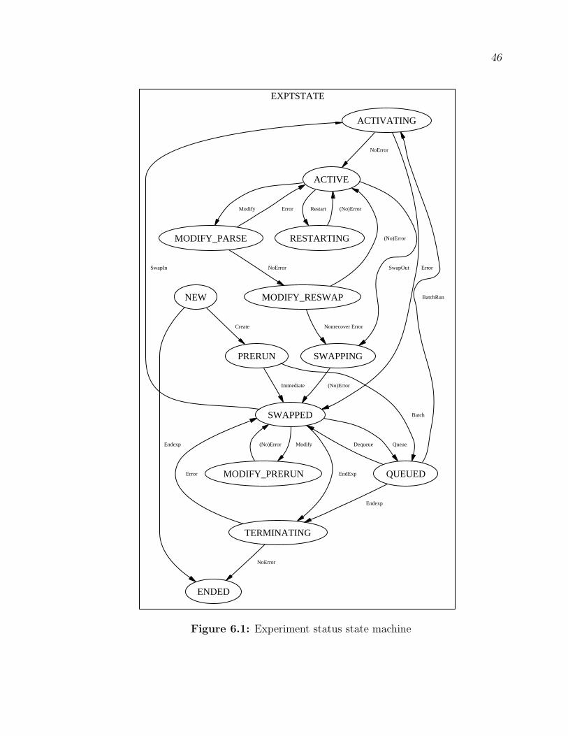
46
EXPTSTATE
ACTIVATING
ACTIVE
NoError
SWAPPED
Error
MODIFY_PARSE
Modify
RESTARTING
Restart
SWAPPING
SwapOutSwapIn
MODIFY_PRERUN
Modify
QUEUED
Queue
TERMINATING
EndExp
Error
MODIFY_RESWAP
NoError
(No)Error
(No)Error
(No)Error
Nonrecover Error
(No)Error
NEW
ENDED
Endexp
PRERUN
Create
Immediate
Batch
BatchRun
Dequeue
Endexp
Error
NoError
Figure 6.1: Experiment status state machine

47
finishes. A swapped experiment may be swapped in again, or may be terminated,
causing it to pass through TERMINATING to ENDED, where the experiment is
deleted.
There are also other actions that can be performed on experiments in some cases.
Experiments may be moved between QUEUED and SWAPPED, as they are taken
in and out of the batch queue by the user. Experiments may be “modified” while
they are swapped or active, passing through either the MODIFY PRERUN state, or
the MODIFY PARSE and MODIFY RESWAP states. Active experiments can also
be restarted, resetting the experiment as if it was just swapped in, which puts it
temporarily in the RESTARTING state.
The variety of different states that experiments help control actions that can
be performed on an experiment. There are only three states where experiments
may remain indefinitely, namely SWAPPED, QUEUED, and ACTIVE. All the other
states are transitional, and the experiment remains in those states for a relatively
short amount of time. Actions like swapin, swapout, modify, enqueue, dequeue,
or terminate cannot be requested when an experiment is in transition. By having
separate states for transitions between stable states, permission checks are greatly
simplified.
The experiment status state machine is managed through a distributed process,
as described in Section 4.3.2, instead of a centralized server, like the node boot state
machines. Each part of the system that performs an action on an experiment checks
its state to verify validity of a requested action before carrying it out, and records
any state transition as necessary. There is no provision for timeouts or triggers in
this machine, and there are no other state machines or “modes” for the experiment
status state machine.
6.2 Node Allocation State Machine
The node allocation state machine is shown in Figure 6.2. This machine is used
to track the progress of a node as it progresses through the allocation/deallocation
cycle that occurs with each node as it is moved into and out of experiments. Unlike

48
NODEALLOC
FREE_CLEAN
RES_INIT_CLEAN
Reserve
RELOAD_TO_DIRTY
Reload
RES_CLEAN_REBOOT
Reboot
RELOAD_PENDING
RELOAD_TO_FREE
Reload
ReloadDone
RES_DIRTY_REBOOT
Reboot
RES_WAIT_DIRTY
Rebooting RES_WAIT_CLEAN
Rebooting
RES_READY
IsUp
IsUp
Free
Figure 6.2: Node allocation state machine

49
the node boot state machines, a node’s state in this machine is not mutually exclusive
of a state in a node boot state machine. Nodes always have a state in each class of
state machine.
A node that is currently allocated to an active experiment is in the RES READY1
state. When it is deallocated, it moves to the RELOAD PENDING state, then as it
begins reloading, it moves to RELOAD TO FREE, and then FREE CLEAN when
the reload is complete.
The node then waits in the FREE CLEAN state until it is reserved, where it
moves to RES INIT CLEAN. If the user has chosen one of operating systems in-
cluded in Emulab’s default disk image, the node is rebooted and moved to the
RES CLEAN REBOOT state. If they have chosen a different OS, the node moves
into RELOAD TO DIRTY as it gets reloaded with the right image, and then to
RES DIRTY REBOOT as it boots. When the node finishes booting, it moves from
the RES CLEAN REBOOT state to the RES WAIT CLEAN state (or from the
RES DIRTY REBOOT state to RES WAIT DIRTY), then finally to RES READY,
where it is completely allocated and configured for use in an experiment.
A node has a state in this state machine, as well as a state in a node boot state
machine, at the same time that the experiment to which the node may be allocated
has a state in the experiment status machine. Transitions and states in each of
these machines may or may not be correlated. Most transitions within the node
allocation machine occur only during the ACTIVATING and SWAPPING states of
the experiment status machine. When an experiment is ACTIVE, its nodes are in
the RES READY state in the node allocation machine, but may be in any state
in a node boot machine. The some transitions in the node allocation machine
correspond to transitions in the node boot state machine, like RES INIT CLEAN
to RES CLEAN REBOOT corresponds to a transition from ISUP to SHUTDOWN
in the node boot machine.
1In state names, RES signifies Reserved, meaning the node is allocated to an experiment. FREEsignifies the opposite. CLEAN signifies that the node is loaded with a pristine copy of the defaultoperating system image. DIRTY means that the node’s disk may have been touched by the user orthe system, or may have been loaded with a different image.

CHAPTER 7
RESULTS
Our results are presented in three parts. First, we present some arguments
based on the exposition in earlier chapters. Second, we present anecdotal evidence
based our our experiences with Emulab’s state machine framework over the last two
years. Third, we present the results of an experiment we performed that provides a
quantitative analysis of one of the improvements brought about by the state machine
framework.
7.1 Arguments
Some of the benefits of the state machine framework are derived directly from the
use of the state machine approach. Many of the virtues of state machines that make
them appropriate for Emulab are described in more detail in Section 3.5.
1. Constructing an explicit model of the processes within the system requires
careful thought and design, both in implementing the system itself and modeling
it. This helps improve the design of the Emulab software architecture and the
correctness of the implementations.
2. The existence of a model, and the visualization of that model, makes it easier to
understand complicated processes involved in managing nodes and experiments.
3. Other benefits have come from the improved monitoring and control that the
framework provides, especially with regard to the node boot state machines
and the stated daemon, as described in Chapters 4 and 5. The addition of
a monitoring daemon that can detect incorrect and unexpected behaviors has
been especially helpful.

51
4. By making more accurate and finer-grained information available to Emulab’s
servers, the framework has contributed to faster and more accurate error detec-
tion, and has helped improve recovery from errors and failures.
5. By improving reliability, the framework has contributed to scalability improve-
ments, making it possible to run larger experiments that were previously im-
practical due to higher failure rates.
6. By improving reliability, our state machine framework has decreased the time
required to swapin experiments and increased the experiment throughput. This
decrease in the time overhead for running an experiment has also made resource
use more efficient.
7. The flexible model has also improved our support for operating system images
that have not been customized with Emulab support, and improved the system’s
workload generality, making it appropriate and capable over a broader range of
experiments.
Overall, it appears that the state machine approach and framework in Emulab
have been very successful, and have improved reliability, scalability, performance and
efficiency, and generality and portability in the system. Of course, our state machine
framework is not perfect, and there are a few downsides:
• Because of its incorporation throughout so many critical parts of the system,
proper operation of Emulab depends very heavily on the stated daemon, and
failures occur when it is not functioning properly. By adding another critical
link in the chain, it can introduce new bugs and complicate debugging.
• The stated daemon has simple rules for what is correct and what is not, and
sends email warnings about many errors that are possibly transient in nature,
requiring a person’s judgment to filter the feedback it provides.
• Because of the centralization of the node boot state machines, it has the poten-
tial to cause scaling issues as Emulab grows in size.

52
• When adding or editing new state triggers or other code contained inside of
stated, it is necessary to restart the daemon, which creates a small window (less
than a second) during which the daemon cannot listen for event notifications.
While the loss of an event may lead to invalid transitions, failure to make a
mode transition, or failure to recognize that a node has booted, these errors
require at most a single reboot for recovery. Still, this possibility discourages
frequent changes to the daemon, and can complicate testing of changes.
7.2 Anecdotal
Emulab’s state machine framework has been observed and evolved over the last
two years, and here we highlight some experiences with it that provide further insight
regarding its benefits and shortcomings. In this section we can also see some of the
important differences between the way the system was before and after the state
machines were added.
7.2.1 Reliability/Performance: Preventing Race Conditions
Emulab is configured to reload every node’s disk after it has participated in an
experiment to ensure a clean environment for the next user of that node. In order
to prevent the node from getting reserved before this reload is complete, the nodes
are reloaded while in a particular holding experiment. A trigger was configured for
the RELOADDONE state of the RELOAD machine, such that stated would free
the node when it finished reloading if it was in the holding experiment, and it would
finish booting into the newly installed OS after being released into the free node pool.
The problem that was encountered was that during times of heavy use, users would
be waiting for Emulab nodes to be freed so they could start their next experiment.
As soon as the nodes finished reloading and were released, they would potentially
get allocated to an experiment, and after having their new settings stored in the
database, they would be rebooted again. Because they hadn’t fully booted after the
reload, they would typically be unresponsive, and would have to be power cycled by
force. Turning off the power to the node during rebooting frequently would cause

53
data loss in the asynchronous file systems typically in use by the OS, and would
leave the file system on disk in an inconsistent and unrecoverable state. Such a node
would of course fail to boot as part of the new experiment, even after multiple reboot
attempts, and at the time, such a failure caused the entire experiment to fail and
abort.1
State machines were the solution for preventing this race condition. The trigger
on RELOADDONE was modified to set up a trigger on the ISUP state for the node
that had finished reloading, that would free the node from the holding experiment.
By delaying the release of the node, the race condition between booting and being
allocated and forcefully rebooted was eliminated. This prevented the disk corruption,
by making sure that nodes were completely rebooted before they could be reserved by
a user, which would make it possible for them to be forcefully rebooted. As a result
of solving the disk corruption problem, reliability was improved, and a significant
amount of time was saved by preventing the node failures and swapin failures and
delays that occurred.
7.2.2 Generality: Graceful Handling of Custom OS Images
Emulab gives users the ability to create customized operating system images, with
whatever OS or disk contents they desire. Because of this, we cannot assume that
any of our standard client side software is running on a node using that image. It is
important that these custom images be able to function, at least minimally, in our
environment.
Without Emulab customizations in the disk image, a node will not be able to
send state notifications to the stated daemon, and the node would be unable to
follow the standard state machine. Nodes normally send notifications as they enter
the SHUTDOWN, TBSETUP and ISUP states. Without the ISUP state, the system
1We have since implemented a swapin retry mechanism that attempts to replace any failednodes with good nodes and try to boot them, without rebooting all the nodes that already bootedsuccessfully. In this case it slows the swapin down by about 15 minutes instead of causing a completefailure.

54
will never recognize a node as having completed booting, and will continue to wait
for it, or reboot it, or determine that it has failed to boot.
Three steps were taken to use our framework to compensate for these situations.
First, we created the MINIMAL state machine, which was composed of SHUTDOWN,
BOOTING, and ISUP states, and eliminated our dependence on the node for the
TBSETUP state. The BOOTING state was already generated by Emulab servers, so
compensating for SHUTDOWN and ISUP still remained.
Second, we changed the state machines to allow a SHUTDOWN notification to be
received while in the SHUTDOWN state, so that duplicate SHUTDOWN events were
not considered invalid, and we changed the node reboot script (which reboots a node)
to send the SHUTDOWN event when rebooting a node. While a call to node reboot
is the most common way to reboot a node, it is not the only way. Most operating
systems can also initiate a reboot from the node itself (i.e., via the reboot or shutdown
commands). In those cases, no event notification will be sent, and a transition from
ISUP to BOOTING would occur. Because this can occur during normal, correct
operation, a valid transition was added to the MINIMAL state machine that allowed
these “silent reboots.”
Third, to compensate for an ISUP event that the node may not be able to send, a
trigger was added to the BOOTING state that would check if an ISUP event needed
to be generated on behalf of the node. There are three cases that the trigger needs to
handle. First, the OS on the node may use the MINIMAL machine, but still support
sending an ISUP2 event, and in that case, we can simply wait for the node to issue
ISUP. Second, if the node doesn’t send ISUP but does respond to ping probes, we
can probe it until it responds, then generate an ISUP on behalf of the node. Third,
if it will not respond to ping packets, we will not be able to determine when it is
ready, so we send an ISUP notification soon after the BOOTING state is entered.
2Each OS image has a set of meta information associated with it that describes some of thefeatures it supports. Among the features recorded there are support for sending ISUP notifications,and support for ping.

55
These steps allowed us to compensate for SHUTDOWN, TBSETUP, and ISUP
events that normally would be sent by the node, and allow Emulab to gracefully
handle any operating system image that a user might use in the testbed, even without
any client side instrumentation of the OS or extra hints about state transitions from
the node itself.
7.2.3 Reliability/Scalability: Improved Timeout Mechanisms
When nodes boot in Emulab, it is important that the system watch for any
problems that may occur during the boot process, and retry as necessary by rebooting
the node again. Determining that a problem has occurred is accomplished by means
of a timeout, and if the node has not booted before the timeout has expired, it is
rebooted to try again. Without state machines and the feedback that state transitions
provide to the system, the method used was a single static timeout for the entire
reboot process.
The single timeout for node reboots suffers from two problems. First, it cannot
monitor progress, because it does not receive feedback from the node, and could not
adapt to compensate for any feedback that it might receive. Because it is a static
timeout and no feedback is present, it has no way of adjusting the timeout based on
what stage of the process is currently in progress. Even though we know that a node
should not take more than a minute or two to load the BIOS and contact the server
for boot information, a failure in that stage cannot be detected until the timeout
expires after several minutes.
Second, there is a critical tradeoff involved, between the time between a failure and
detection of that failure, and the rate of false positives, where a failure is perceived
when none occurred. To eliminate false positives, the timeout would have to be larger
than the maximum time that a node could take to boot without encountering a failure,
which in our case is estimated at 15 minutes. However, nodes failures most frequently
occur during the first 4 minutes of the boot process, and a 15-minute timeout would
add a delay of about 11 minutes before a failure would be detected. The way Emulab
handled this tradeoff was by setting the timeout a reasonable amount of time greater

56
than the average time to boot, but significantly less than the maximum error-free
boot time, by choosing a 7-minute timeout.
State timeouts provide a much improved mechanism for determining when a
node has failed during booting. State transitions allow progress to be monitored,
and state timeouts provide a much finer granularity, and can be context sensitive,
since different states have different timeouts. The value of these improvements was
quantified experimentally and those results are described in Section 7.3.
7.2.4 Generality: Adding New Node Types
Emulab is a constantly evolving and growing testbed, and includes a wide vari-
ety of different device types, from powerful PCs and network devices to embedded
processors and miniature mobile wireless devices. The various aspects of the system
must be able to gracefully allow the adaptation and evolution as the hardware base
of the testbed becomes more diverse.
The incorporation of a state machine framework inside Emulab began when the
hardware base consisted of a cluster of PCs. As time has passed, six more types
of emulab nodes have been added, and several others are in progress or planned for
addition in the near future. These new node types include IXP Network Processors[12]
nodes, “virtual” nodes[9, 6] (jail virtual machines running on cluster PCs), wide-area
nodes (with live Internet links), PlanetLab[18] nodes, and “simulated” nodes (nodes
simulated inside an instance of nse[4], the ns emulator). In the near future, several
types of wireless nodes will be added, potentially including stationary wireless PCs,
low-power stationary wireless devices, mobile wireless PDA devices, including devices
carried by people or attached to model trains or radio controlled cars.
We have found that the state machine approach has proven to be very flexible,
and is able to elegantly and simply encompass the new needs brought about by the
new node types. Of the five types that have already been added, two new state
machines were created, and the rest already fit with existing state machines. Only
one of the new state machines required any changes to the stated daemon, in order
to add a new trigger. Typically, new node types either exactly match an existing
57
machine, or require only slight changes, like adding or deleting a state or transition.
The ease of adding new state machines and node types is an important consideration
in determining the generality and maintainability of the system.
7.2.5 Reliability/Scalability/Performance: Access Control/Locking
Every aspect of Emulab is controlled by some access control mechanism, based on
the user’s access levels to various projects and experiments, and on the current node
allocations. Along with these access controls are a set of locks that serve to prevent
user actions from interrupting system processes as much as possible.
The required permission checks can be quite complicated, and typically get per-
formed quite often, since even viewing a web page requires permission checks to
occur. The access controls must verify that the user is a member of the project
of the experiment or node in question, and that they have been granted sufficient
access to perform the requested operation. Even when a user has access to a project,
experiment, or node, the actions that are allowed vary widely over time, depending
on the activity in which the entity may be involved. For example, nodes cannot be
rebooted while a reboot is in progress under most circumstances, and many actions
on experiments are not allowed when the experiment is swapping in or out.
The state machine framework contributes to improved locking and synchronization
between different components of the system, and simplifies permission checking on
locked entities. The current state of the entity, as recorded in the database, makes
access control much simpler, and prevents users from initiating illegal actions. They
also serve a similar purpose internally. For example, an experiment cannot move into
the ACTIVE state until every node in the experiment has entered the RES READY
state in the node allocation machine, which cannot occur until the node has entered
the ISUP state in its node boot machine. Similar constraints provide features similar
to barrier synchronization, and automatically “lock” entities against certain actions
as state transitions occur.

58
7.2.6 Reliability: Detecting Unexpected Behaviors
Because an advanced network testbed like Emulab is a complex distributed system
involving hundreds of computers, unexpected things can and do occur. While Em-
ulab’s servers are watched closely and keep many logs, the nodes themselves do not
generate persistent logs other than the log of the serial console, and any information
that can be gathered about a node is very helpful in finding and diagnosing errors
and other unexpected results.
One of the first things that state machines were used to accomplish was to
attempt to track down some mysterious and apparently spontaneous node reboots.
Nodes would appear to reboot for no apparent reason, and in an effort to diagnose
it, the state machine framework was used to alert developers when such an error
occurred. When a reboot occurs without properly transitioning to the SHUTDOWN
state, the node moves from the ISUP state directly to the BOOTING state. This
transition is not a valid transition in the state machine, and it generates a message
to administrators. By watching for these errors and giving administrators a chance
to examine the nodes before their disks were reloaded, these problems were able to
be diagnosed and solved. The monitoring that the state machines provide continues
to serve as an ongoing watchdog for many varieties of unexpected behavior.
7.3 Experimental
There are very few measurements or metrics that can appropriately measure the
benefits of adding state machines to Emulab. One measurement that can quantify one
aspect of the benefit of state machines is the time required to swap in an experiment.
As described in Section 7.2.3, state machines allow for fine-grained, context-sensitive,
timeouts and retries, which can provide big speed and reliability improvements over
the alternative of a single static timeout.
In Emulab, the worst-case time to reboot a node without having a failure or undue
delays is over 15 minutes, but the average time is under four minutes. If we retry
a failed reboot once before giving up on a node, we could end up waiting for 30
minutes. Before state machines were added, a timeout of seven minutes was chosen,

59
approximately double the normal boot time, because it minimized false timeouts
while keeping the maximum delay reasonable. Emulab also implements a swapin
retry feature that will replace any failed nodes with new ones, and attempt up to two
retries before considering a swapin as a failure.
With state machines handling timeouts during the booting process, progress can
be taken into account, and timeouts are all context-sensitive to the current state
of the node. To give an idea of the timeouts, Table 7.1 shows some typical state
timeouts. With context-sensitive timeouts, we no longer have to assume worst-case
performance for states we know we have passed, or for states we have not entered
yet. For instance, a single timeout based on the worst case numbers in the table,
would be 15 minutes, and the full 15 minutes would have to elapse before a timeout
is detected. If a node goes through SHUTDOWN in one minute, and gets stuck in
BOOTING, we do not even have to wait five minutes, the worst case time to get
through SHUTDOWN and BOOTING. We have to wait until only 3 minutes have
elapsed since entering the BOOTING state, or a total of 4 minutes have elapsed since
we started. Note that we also do not have to wait 7 minutes, like the normal single
timeout would indicate, because we know that we do not have to consider the time
taken in TBSETUP.
To provide additional evidence of the improvement provided by state machines,
an experiment was devised in which a standard part of the TBSETUP state was
prolonged. As Emulab nodes boot, they self configure, including the installation of
any RPM or tar packages, as part of the TBSETUP state. An experiment was
configured containing a single node that loads an RPM that takes eight minutes to
install. This experiment was then swapped in using a version of the Emulab software
State TimeoutSHUTDOWN 2 min.BOOTING 3 min.TBSETUP 10 min.
Table 7.1. Typical state timeout values

60
that does not base timeouts on states while preparing nodes for an experiment,
and then swapped in again using newer software that does use state timeouts while
rebooting nodes.
The result of the attempted swapin with a single timeout was that the node
would start booting, entering TBSETUP after about 1 minute, then start installing
the RPM package. After another 6 minutes, Emulab would time out, and reboot
the node. The same boot process would occur after the reboot, and it would time
out again, at which time Emulab determined the node was unusable, and replaced
it with a different node, and attempted the swapin again. The new node timed out
two more times, leading to another swapin retry, which had the same result. By the
time Emulab finally determined the swapin attempt was a failure, it had tried three
different nodes, rebooting them a total of six times, waiting seven minutes each time.
The total time for the attempted swapin was about 45 minutes, and ended in failure.
The swapin with state-based timeouts had a very different result. The swapin was
started, a node was chosen, and it was rebooted, progressing through BOOTING and
starting TBSETUP in about 1 minute. Because TBSETUP is currently allowed to
take up to 10 minutes without causing a timeout, installation of the RPM completed
before a timeout occurred, and the node entered ISUP. The experiment swapin was
then complete, without any failures or retries, in about 9 minutes, and was successful.
This example illustrates just one way where state machines provided a tangible
and quantifiable improvement to the system. By providing more accurate information
to Emulab servers, and allowing fine-grained, context-sensitive timeouts and retries,
reliability was increased, and in turn, performance dramatically improved. Better
reliability and performance also positively affect scalability and efficiency.

CHAPTER 8
RELATED WORK
In this chapter, we describe four categories of research related to the research
described in this thesis. First, work in the area of basic state machines and automata
is described, including a variation called timed automata. Second, we discuss Message
Sequence Charts (MSCs) and some of the similarities they share with our work.
Third, UML statecharts are described, including some similarities and analogous
functionality in their model. The fourth category is research related to testbeds or
distributed systems that describes methods or models similar to our work.
8.1 State Machines and Automata
State machines have been a popular approach for many years, and are the basis for
the ideas and implementations presented in this thesis. They are also known as Finite
State Machines (FSMs), Finite Automata (FAs), or Finite State Automata (FSAs).
They are also often categorized into Deterministic or Nondeterministic automata
(DFAs and NFAs). The state machines in this thesis are most closely related to
DFAs.
A state automaton is traditionally composed of five parts: a set of states, the
alphabet, the transition function, an initial state, and a set of accepting (or final)
states[11]. In our case, the set of states is enumerated in Emulab’s database, and the
alphabet is implicitly defined as the set of events that may trigger a transition. The
transition function is specified as entries in a table in the database, identifying the
current state and a possible valid next state. Because the state machines in Emulab
are designed to run constantly, there is no notion of an initial state or a final state,
just a cycle defined by the transition function.

62
8.1.1 Timed Automata
Previous work with automata introduced the notion of a clock for use in conjunc-
tion with a state machine approach. One example is the “timed automata” model[1],
which adds a global clock to the state machine approach. The clock’s state can be
used when deciding when a transition should be made and what new state should
be entered. This global clock differs from the notion of timeouts described in this
thesis because the timeouts establish time measured from entry into the current state,
instead of a global notion of the passing of time, measured from a single starting point.
8.2 Message Sequence Charts and Scenarios
Message Sequence Charts (MSCs) and Live Sequence Charts (LSCs)[3] have a
concept of “scenarios” that are linked together in configurations similar to state
machines. Each of these scenarios in turn represents a particular MSC that describes
operation within that scenario, forming a type of hierarchy similar to the way Emulab
uses modes and state machines.
These scenarios and the transitions between them can be compared to the “modes”
and mode transitions described in this thesis, where modes and scenarios and the
transitions between them form a state machine at one level, and at the same time
represent lower-level objects (state machines or MSCs) that define operation within
that mode.
MSCs have also been combined with timed automata, as described by Lucas[16].
8.3 Statecharts in UML
The Unified Modeling Language (UML)[2, 22] includes a model of state machines
called statecharts[7, 8], which describe a significant amount of extra functionality
beyond that provided by the standard automata model. Statecharts include all of the
machinery and functionality necessary to describe the designs and implementations
described in this thesis, however, because they were conceived independently, the
terms used are often different.

63
In statecharts, the analogue for the state “triggers” used in Emulab are “entry
actions,” which are simply actions that get performed when a state is entered. Sim-
ilarly, the hierarchical features of UML statecharts are similar to the separate state
machines and “modes” we use.
Statecharts also are capable of capturing the state timeout functionality we imple-
mented in Emulab, but only in a somewhat awkward and convoluted way. Statecharts
may have “internal transitions,” which are transitions in which no state change occurs,
and no entry or exit actions are triggered. The UML keyword “after” also allows for
events based on the passage of time, “after(10 seconds)” for example. By combining
these two features, with appropriate internal data to track total time elapsed within
the state, statecharts can provide functionality similar to our state timeouts.
8.4 Testbed Related Work
For detailed information on research related to network testbeds, please see our
other publications about Emulab ([9, 10, 24, 25, 26, 27]; future ones will be listed
on the Emulab web site at www.emulab.net). At the time of publication, the author
is unaware of any related work regarding the use of state machines in combination
with testbeds, and unable to locate any publications regarding similar uses of state
machines in other large distributed systems.

CHAPTER 9
CONCLUSIONS AND FUTURE WORK
Faced with reliability and performance problems in the Emulab network testbed,
we implemented a process monitoring framework based on state machines to address
the issues. Three classes of state machines were introduced, including node boot,
experiment status, and node allocation state machines. As described in Section 4.4,
a centralized service, stated, was developed to provide enhanced monitoring and
control for the node boot state machines discussed in Chapter 5. This daemon
manages transitions from one mode or state machine to another, detects invalid state
transitions, and aids in recovery from failures. The experiment status and node
allocation state machines, described in Chapter 6, use a distributed control model,
and are primarily used to provide access control, locking, and synchronization.
In this thesis we have shown that enhancing Emulab with better monitoring and
control through a flexible framework based on state machines improves the reliabil-
ity, scalability, performance, efficiency, and generality of the system. As discussed
in Chapter 7, Emulab’s process monitoring framework has provided formalization
and visualization of several processes involved in the testbed. Improved monitoring
and control has enabled detection of incorrect behaviors and contributed to faster
and more accurate error detection and recovery. The reliability improvements have
increased scalability and performance, by helping the system run faster with increased
throughput and better efficiency. Generality improvements include better support for
customized operating system images, and better flexibility for adding new node types
to Emulab. These benefits have been discussed through arguments, anecdotes, and
evaluated experimentally.

65
Although we have made significant improvements in Emulab, there are a number
of possibilities for future work involving state machines in Emulab. These include
further development of the distributed control model described in Section 4.3.2,
better heuristics for detecting meaningful errors, implementing more concepts and
functionality from related state machine systems, and migrating more state machine
functionality into the database.
At present, the distributed control model used for experiment status and node
allocation state machines lacks several of the features used by the node boot state
machines that use a centralized model. Some of the features that could be added to the
distributed model are timeouts, triggers, and better detection of invalid transitions.
There are two obvious possibilities for implementing these changes. The first would
be to enhance the distributed model directly, but this may prove problematic for
timeouts due to the lack of a monitoring process for detecting the timeouts. The
second method would be to change the state machines to the centralized model,
where they could take advantage of the existing implementation used by the node
boot state machines.
When stated detects an invalid transition, it notifies an administrator that there
was an error, so that the error can be examined. While useful in general, this can
sometimes result in a significant number of messages that are unrelated, and cannot
individually be traced back to a cause and resolved. It would be beneficial to add
to stated more intelligent heuristics for deciding when to notify an administrator.
The heuristic most often used by humans is to look for clusters of similar or related
errors. The clustering indicates that one cause may be responsible for the cluster, and
that the problem is occurring repeatedly, and may be repeatable enough to debug.
Heuristics could detect clusters of related messages within a short time frame, such
as several nodes with the same error, or a single node with multiple errors, and only
notify administrators about those errors. Such heuristics would make it less likely
that real problems may get ignored due to too much background noise in the message
stream.

66
A third possibility that seems promising is implementing more ideas from related
state machine systems, such as the UML statecharts from Section 8.3, for example.
Currently, stated has support for analogues to entry actions and hierarchical state
machines. Other features, like exit actions, guarded transitions, and others, might be
usefully added to Emulab. If this functionality were present in stated, it is possible
that some of the things currently being modeled with triggers would be better modeled
with exit actions rather than entry actions. Guarded transitions would also enhance
our state machine approach, making it more rich and descriptive, and would allow
for changes simply by changing the model without changing the program that causes
the event to be sent.
Another possibility for future work would be to migrate more state machine func-
tionality into the database in declarative form, rather than putting it in imperative
program code, like the triggers that are implemented as part of stated, for example.
Currently each type of trigger must be implemented as a section of Perl code within
the stated program, which is awkward to analyze and evolve. By describing the
actions the trigger should take in the database rather than in stated, it would make
it easier to make changes, and better separate the code for the monitoring framework
from the state machine itself. It would allow more of the transition logic to be included
in the state machine description, in a declarative fashion, rather than as imperative
code in the program that decides which event to send. If combined with changes to
make the framework provide a richer model by adding more statechart-like features,
for instance, the task of moving more functionality into the database would likely be
significantly easier.

REFERENCES
[1] Alur, R., and Dill, D. L. A theory of timed automata. Theoretical ComputerScience 126, 2 (1994), 183–235.
[2] Booch, G., Rumbaugh, J., and Jacobson, I. The Unified ModelingLanguage User Guide. Addison-Wesley, 1998.
[3] Damm, W., and Harel, D. LSCs: Breathing life into message sequencecharts. Formal Methods in System Design 19, 1 (2001), 45–80.
[4] Fall, K. Network emulation in the Vint/NS simulator. In Proc. 4th IEEESymp. on Computers and Communications (1999).
[5] Gelinas, J. Virtual private servers and security contexts. Available fromhttp://www.solucorp.qc.ca/miscprj/s context.hc, 2002.
[6] Guruprasad, S., Stoller, L., Hibler, M., and Lepreau, J. Scal-ing network emulation with multiplexed virtual resources. SIGCOMM 2003Poster Abstract, August 2003. http://www.cs.utah.edu/flux/papers/scaling-sigcomm03/posterabs.pdf.
[7] Harel, D. Statecharts: A visual formalism for complex systems. Science ofComputer Programming 8, 3 (June 1987), 231–274.
[8] Harel, D., and Politi, M. Modeling Reactive Systems with Statecharts: TheStatemate Approach. McGraw-Hill, Inc., 1998.
[9] Hibler, M., et al. Virtualization techniques for network experimentation.Flux Group Technical Note 2004-01, Univ. of Utah School of Computing,February 2004. Submitted for publication. Available at http://www.cs.utah.-edu/flux/papers/virt-ftn2004-01.pdf.
[10] Hibler, M., Stoller, L., Lepreau, J., Ricci, R., and Barb, C. Fast,scalable disk imaging with frisbee. In Proc. of the 2003 USENIX Annual Tech-nical Conf. (San Antonio, TX, June 2003), USENIX Association, pp. 283–296.
[11] Hopcroft, J., and Ullman, J. Introduction to Automata Theory, Languages,and Computation. Addison-Wesley, Reading, Massachusetts, 1979.
[12] Intel Corp. Ixp1200. http://www.intel.com/design/network/products/-npfamily/ixp1200.htm.
[13] Internet2 Consortium. Internet2. http://www.internet2.edu/.

68
[14] Kamp, P.-H., and Watson, R. N. M. Jails: Confining the omnipotent root.In Proc. 2nd Intl. SANE Conference (May 2000).
[15] Linux vserver project. http://www.linux-vserver.org/.
[16] Lucas, P. Timed semantics of message sequence charts based on timed au-tomata. In Electronic Notes in Theoretical Computer Science (2002), E. Asarin,O. Maler, and S. Yovine, Eds., vol. 65, Elsevier.
[17] NSF Workshop on Network Research Testbeds. Workshop Re-port. http://gaia.cs.umass.edu/testbed workshop/testbed workshop report -final.pdf, Nov. 2002.
[18] Peterson, L., Anderson, T., Culler, D., and Roscoe, T. A blueprintfor introducing disruptive technology into the internet. In Proc. of HotNets-I(Princeton, NJ, Oct. 2002).
[19] Rizzo, L. Dummynet home page. http://www.iet.unipi.it/~luigi/-ip dummynet/.
[20] Rizzo, L. Dummynet: a simple approach to the evaluation of network protocols.Computer Communication Review 27, 1 (Jan. 1997), 31–41.
[21] Rizzo, L. Dummynet and forward error correction. In Proc. of the 1998USENIX Annual Technical Conf. (New Orleans, LA, June 1998), USENIXAssociation.
[22] Rumbaugh, J., Jacobson, I., and Booch, G. The Unified ModelingLanguage Reference Manual. Addison-Wesley, 1998.
[23] The VINT Project. The ns Manual, Apr. 2002. http://www.isi.edu/nsnam/-ns/ns-documentation.html.
[24] White, B., Lepreau, J., and Guruprasad, S. Lowering the barrier towireless and mobile experimentation. In Proc. HotNets-I (Princeton, NJ, Oct.2002).
[25] White, B., Lepreau, J., and Guruprasad, S. Wireless andmobile Netscope: An automated, programmable testbed. http://-
www.cs.utah.edu/̃lepreau/emulab-wireless.ps. Submitted for publication in Mo-bicom’02., Mar. 2002.
[26] White, B., Lepreau, J., Stoller, L., Ricci, R., Guruprasad, S.,Newbold, M., Hibler, M., Barb, C., and Joglekar, A. An integratedexperimental environment for distributed systems and networks. In Proc. of theFifth Symposium on Operating Systems Design and Implementation (Boston,MA, Dec. 2002), pp. 255–270.

69
[27] White, B., Lepreau, J., Stoller, L., Ricci, R., Guruprasad, S.,Newbold, M., Hibler, M., Barb, C., and Joglekar, A. An integratedexperimental environment for distributed systems and networks (full report).http://www.cs.utah.edu/flux/papers/emulabtr02.pdf, May 2002.