reliability considerations and fault-handling - tobias geyer
TRANSCRIPT

2442 IEEE TRANSACTIONS ON INDUSTRY APPLICATIONS, VOL. 46, NO. 6, NOVEMBER/DECEMBER 2010
Reliability Considerations and Fault-HandlingStrategies for Multi-MW Modular Drive Systems
Tobias Geyer, Senior Member, IEEE, and Stefan Schröder, Member, IEEE
Abstract—Shunt-interleaved electrical drive systems consistingof several parallel medium-voltage back-to-back converters enablepower ratings of tens of MVA, low current distortions, and avery smooth air-gap torque. To meet stringent reliability andavailability goals despite the large parts count, the modularity ofthe drive system needs to be exploited and a suitable fault-handlingstrategy that allows the exclusion and isolation of faulted threadsis required. This avoids the shutdown of the complete systemand enables the drive system to continue operation. If full powercapability is also required in degraded mode operation, redun-dancy on a thread level needs to be added. Experimental resultsconfirm that thread exclusion allows the isolation of the majorityof faults without affecting the mechanical load. As the drive systemcontinues to run, faulted threads can be repaired and then addedon-the-fly to the running system by thread inclusion. As a result,the downtime of such a modular drive system is expected to notexceed a few hours per year.
Index Terms—Electrical drive, fault handling, medium-voltagedrive, modular drive system, multilevel converter, redundancy,reliability.
I. INTRODUCTION
ONE WAY to achieve very high power levels in the range oftens of MVA is to operate several back-to-back converters
(threads) in parallel. A de facto industrial standard for such athread is the three-level medium-voltage neutral point clamped(NPC) converter using integrated gate commutated thyristors(IGCT) as switching devices. Such a thread is usually rated at8–12 MVA. Often, the N parallel threads are tightly coupledwith very small inductances and the same switching patternis applied to each of the threads. By doing this, the machinevoltage resembles a three-level NPC inverter with effectivelyN times the thread power rating [5].
In many applications, however, a very smooth machinecurrent and air-gap torque is required. This can be achievedby coupling the threads with larger inductors (i.e., coupling
Manuscript received November 26, 2009; revised January 26, 2010; acceptedMarch 28, 2010. Date of publication August 26, 2010; date of current versionNovember 19, 2010. Paper 2009-IDC-450.R1, presented at the 2009 IEEEEnergy Conversion Congress and Exposition, San Jose, CA, September 20–24,and approved for publication in the IEEE TRANSACTIONS ON INDUSTRY
APPLICATIONS by the Industrial Drives Committee of the IEEE IndustryApplications Society.
T. Geyer was with GE Global Research, 85748 Garching bei München,Germany. He is now with the Department of Electrical and Computer Engi-neering, The University of Auckland, Auckland 1142, New Zealand (e-mail:[email protected]).
S. Schröder is with GE Global Research, 85748 Garching bei München,Germany (e-mail: [email protected]).
Color versions of one or more of the figures in this paper are available onlineat http://ieeexplore.ieee.org.
Digital Object Identifier 10.1109/TIA.2010.2070477
inductors in the range of a quarter pu referred to the thread).This allows one to apply thread-specific switching patternsthat are optimized such that the resulting average switchingpatterns at the points of common coupling (the machine orthe grid) exhibit significantly finer steps and resemble a higherswitching frequency. One way to achieve this is to shift thepulse width modulation (PWM) carrier signal by a certain phaseshift among the threads giving rise to the concept of interleav-ing, see, e.g., [6] and [17]. As a result, the system’s machineand grid voltages effectively resemble a 2N + 1 level inverterwith N times the power rating. For details on interleaving andexperimental results of a 35-MW drive, the reader is referredto [11].
In both cases, compared to the standard application with onethread, the part count for the N -thread system is increasedby approximately N times. This impacts on the system re-liability and availability in an adverse way if no appropriatecountermeasures are taken. On the other hand, the parallelthread arrangement can be exploited to add redundancy [10].Moreover, in the event of severe faults, the coupling inductorslimit the instantaneous currents, confine the fault to one thread,and thus allow the isolation and removal of the faulted threadby an appropriate fault-handling strategy.
In more traditional drive systems (with one thread), thereliability can be boosted by adding redundancy within thethread on a device level. This option is typically employedin thyristor-based converters (LCIs). In PWM-type converters,examples of this approach include redundant semiconductorswitches [15] and adding a fourth redundant inverter leg [3].Alternatively, by installing multiple threads in parallel, redun-dancy is added on a thread level [12], [17]. Another option isto use multiphase machines fed by several inverters arranged inparallel, where each inverter feeds a three-phase group of themachine independently [2].
Reliability considerations and an optimized fault-handlingstrategy for shunt-interleaved drive systems are the focus ofthis paper. Specifically, after outlining the drive system topol-ogy and the control scheme in Section II and recalling therequired reliability terminology and mathematical formulas inSection III, the paper derives the failure rates of the commonpart and the threads in Section IV. Section V compares thereliability of a N -thread system (without redundancy) with thereliability of a N + 1 thread system (with redundancy). Basedon the fault classification in Section VI, Section VII proposesa suitable fault-handling strategy that is straightforward toimplement and is expected to yield an availability close to100%. Experimental results are provided in Section VIII andthe paper is summarized in Section IX.
0093-9994/$26.00 © 2010 IEEE

GEYER AND SCHRÖDER: RELIABILITY CONSIDERATIONS AND FAULT-HANDLING STRATEGIES FOR MODULAR DRIVE SYSTEMS 2443
Fig. 1. Modular drive system with N shunt-interleaved threads (here N = 3).The system consists of the main breaker, N grid-side breakers, N thread trans-formers, N back-to-back converters, N machine-side breakers, N couplinginductors, and a synchronous machine.
Fig. 2. Detailed schematic of one of the back-to-back converters, whichconsists of two three-level NPC voltage source inverters coupled by a dc-link.
II. DRIVE SYSTEM TOPOLOGY AND CONTROL SCHEME
A. Drive System Topology
The modular structure of the drive system topology with itsN threads is shown in Fig. 1 [1], [11]. Each thread consists ofa grid-side circuit breaker, a transformer, an active front end(AFE), which is often also referred to as an active rectifier, adc-link, an inverter (INV), a machine-side circuit breaker, anda coupling inductor.
In this paper, the AFEs and inverters are three-level NPCconverters using 4.5 kV and 4 kA IGCTs (see Fig. 2). Themachine is a synchronous machine, which is fed by an in-tegrated brushless exciter using a rotating three-phase diodebridge.
B. Control Scheme
The controller on the machine side comprises the machineand the N individual thread control processes, which run inparallel. The machine process controls the machine current,which is the instantaneous sum of the N inverter currents.The machine controller is based on a state-of-the-art field-oriented control scheme working in a field-oriented orthogonalcoordinate system. The flux errors are mapped into a flux-producing (direct) current reference, while the torque referenceis translated into an orthogonal torque-producing (quadrature)current reference. In steady state, the machine is completelyfluxed via the field current supplied by the brushless exciter.
The N INV processes ensure the equal sharing of themachine current among the threads. This is achieved by Nindividual processes that regulate the difference between theinverter current and the machine current divided by N tozero. The resulting voltage command is sent to the INV I/O
module, which generates the firing pulses and senses the INVcurrents.
The control scheme on the grid side is simpler. The AFEscontrol their dc-link voltages individually. A master phase-locked loop (PLL) keeps the AFE controllers synchronized tothe grid and phase-shifted among each other.
The voltage and current waveforms of the machine andgrid, respectively, are significantly improved by interleaving theN threads, i.e., by phase-shifting the PWM carrier signals. Thisconcept and its benefits are explained in detail in [11] alongwith experimental results.
III. RELIABILITY CONSIDERATIONS
Throughout the paper, we will pursue a bottom-up approachto determine and evaluate the reliability of the complete drivesystem. More specifically, the system is broken up into itscomponents and the failure rates of these components aredetermined based on manufacturer data and/or field experi-ence. The component failure rates are then aggregated to ob-tain the expected system failure rate and the overall systemreliability.
A. Terminology and Definitions
Before proceeding, it is beneficial to recall some basic termi-nology and definitions related to reliability [4], [9].
• Reliability: The reliability R is the characteristic of asystem or component expressed by the probability that itwill perform a required function under stated conditionsfor a stated period of time.
• Failure rate: The failure rate λ is the frequency with whicha system or component fails. Usually, the failure rate isgiven in failures in time (FIT), where 1 FIT is equal to onefailure within one billion (109) hours.
• MTBF: The mean time between failures (MTBF) of asystem or component is the average time between twofailures of the said system or component. Assuming aconstant failure rate with respect to time (neglecting earlyfailures and aging) and ignoring the time to recover froma failure, the MTBF is the inverse of the failure rate
MTBF =1λ
. (1)
The MTBF is usually given in hours.• MTTR: The mean time to repair (MTTR) is the average
time to repair a failed system or component. It is usuallygiven in hours and is the inverse of the repair rate μ
MTTR =1μ
. (2)
• Availability: Availability is the proportion of time a systemor component is in a functioning condition and thus avail-able to provide the specified function. The availability isgiven by
A =MTBF
MTBF + MTTR. (3)
2444 IEEE TRANSACTIONS ON INDUSTRY APPLICATIONS, VOL. 46, NO. 6, NOVEMBER/DECEMBER 2010
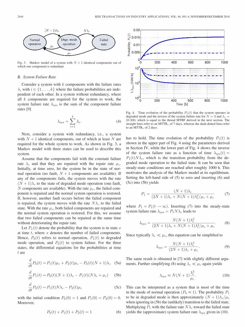
Fig. 3. Markov model of a system with N + 1 identical components out ofwhich one component is redundant.
B. System Failure Rate
Consider a system with k components with the failure ratesλi with i ∈ {1, . . . , k} where the failure probabilities are inde-pendent of each other. In a system without redundancy, whereall k components are required for the system to work, thesystem failure rate λsys is the sum of the component failurerates [9]
λsys =k∑
i=1
λi. (4)
Next, consider a system with redundancy, i.e., a systemwith N + 1 identical components, out of which at least N arerequired for the whole system to work. As shown in Fig. 3, aMarkov model with three states can be used to describe thissystem.
Assume that the components fail with the constant failurerate λc and that they are repaired with the repair rate μc.Initially, at time zero, let the system be in the state of nor-mal operation (no fault, N + 1 components are available). Ifany of the components fails, the system moves with the rate(N + 1)λc to the state of degraded mode operation (one fault,N components are available). With the rate μc, the failed com-ponent is repaired and the normal system operation is restored.If, however, another fault occurs before the failed componentis repaired, the system moves with the rate Nλc to the failedstate. With the rate μc, both failed components are repaired andthe normal system operation is restored. For this, we assumethat two failed components can be repaired at the same timewithout deteriorating the repair rate.
Let Px(t) denote the probability that the system is in state xat time t, where x denotes the number of failed components.Hence, P0(t) refers to normal operation, P1(t) to degradedmode operation, and P2(t) to system failure. For the threestates, the differential equations for the probabilities at timet are
d
dtP0(t) =P1(t)μc + P2(t)μc − P0(t)(N + 1)λc (5a)
d
dtP1(t) =P0(t)(N + 1)λc − P1(t)(Nλc + μc) (5b)
d
dtP2(t) =P1(t)Nλc − P2(t)μc (5c)
with the initial condition P0(0) = 1 and P1(0) = P2(0) = 0.Moreover,
P0(t) + P1(t) + P2(t) = 1 (6)
Fig. 4. Time evolution of the probability P1(t) that the system operates indegraded mode and the inverse of the system failure rate for N = 3 and λc =23 300, which is equal to the thread MTBF derived in the next section. Thestraight lines refer to an MTTRc of 7 days, whereas the dash-dotted lines referto an MTTRc of 2 days.
has to hold. The time evolution of the probability P1(t) isshown in the upper part of Fig. 4 using the parameters derivedin Section IV, while the lower part of Fig. 4 shows the inverseof the system failure rate as a function of time λsys(t) =P1(t)Nλc, which is the transition probability from the de-graded mode operation to the failed state. It can be seen thatsteady-state conditions are reached after roughly 1000 h. Thismotivates the analysis of the Markov model at its equilibrium.Setting the left-hand side of (5) to zero and inserting (6) and(5c) into (5b) yields
P1 =(N + 1)λc
(2N + 1)λc + N(N + 1)λ2c/μc + μc
(7)
where P1 = P1(t → ∞). Inserting (7) into the steady-statesystem failure rate λsys = P1Nλc leads to
λsys =N(N + 1)λ2
c
(2N + 1)λc + N(N + 1)λ2c/μc + μc
. (8)
Since typically λc � μc, this equation can be simplified to
λsys =N(N + 1)λ2
c
(2N + 1)λc + μc. (9)
The same result is obtained in [7] with slightly different argu-ments. Further simplifying (8) using λc � μc again yields
λsys ≈ N(N + 1)λ2
c
μc. (10)
This can be interpreted as a system that is most of the timein the mode of normal operation (P0 ≈ 1). The probability P1
to be in degraded mode is then approximately (N + 1)λc/μc
when ignoring in (5b) the (unlikely) transition to the failed state.Multiplying P1 with the failure rate Nλc toward the failed stateyields the (approximate) system failure rate λsys given in (10).
GEYER AND SCHRÖDER: RELIABILITY CONSIDERATIONS AND FAULT-HANDLING STRATEGIES FOR MODULAR DRIVE SYSTEMS 2445
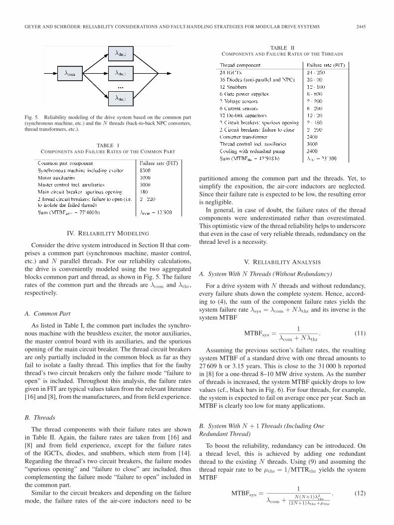
Fig. 5. Reliability modeling of the drive system based on the common part(synchronous machine, etc.) and the N threads (back-to-back NPC converters,thread transformers, etc.).
TABLE ICOMPONENTS AND FAILURE RATES OF THE COMMON PART
IV. RELIABILITY MODELING
Consider the drive system introduced in Section II that com-prises a common part (synchronous machine, master control,etc.) and N parallel threads. For our reliability calculations,the drive is conveniently modeled using the two aggregatedblocks common part and thread, as shown in Fig. 5. The failurerates of the common part and the threads are λcom and λthr,respectively.
A. Common Part
As listed in Table I, the common part includes the synchro-nous machine with the brushless exciter, the motor auxiliaries,the master control board with its auxiliaries, and the spuriousopening of the main circuit breaker. The thread circuit breakersare only partially included in the common block as far as theyfail to isolate a faulty thread. This implies that for the faultythread’s two circuit breakers only the failure mode “failure toopen” is included. Throughout this analysis, the failure ratesgiven in FIT are typical values taken from the relevant literature[16] and [8], from the manufacturers, and from field experience.
B. Threads
The thread components with their failure rates are shownin Table II. Again, the failure rates are taken from [16] and[8] and from field experience, except for the failure ratesof the IGCTs, diodes, and snubbers, which stem from [14].Regarding the thread’s two circuit breakers, the failure modes“spurious opening” and “failure to close” are included, thuscomplementing the failure mode “failure to open” included inthe common part.
Similar to the circuit breakers and depending on the failuremode, the failure rates of the air-core inductors need to be
TABLE IICOMPONENTS AND FAILURE RATES OF THE THREADS
partitioned among the common part and the threads. Yet, tosimplify the exposition, the air-core inductors are neglected.Since their failure rate is expected to be low, the resulting erroris negligible.
In general, in case of doubt, the failure rates of the threadcomponents were underestimated rather than overestimated.This optimistic view of the thread reliability helps to underscorethat even in the case of very reliable threads, redundancy on thethread level is a necessity.
V. RELIABILITY ANALYSIS
A. System With N Threads (Without Redundancy)
For a drive system with N threads and without redundancy,every failure shuts down the complete system. Hence, accord-ing to (4), the sum of the component failure rates yields thesystem failure rate λsys = λcom + Nλthr and its inverse is thesystem MTBF
MTBFsys =1
λcom + Nλthr. (11)
Assuming the previous section’s failure rates, the resultingsystem MTBF of a standard drive with one thread amounts to27 609 h or 3.15 years. This is close to the 31 000 h reportedin [8] for a one-thread 8–10 MW drive system. As the numberof threads is increased, the system MTBF quickly drops to lowvalues (cf., black bars in Fig. 6). For four threads, for example,the system is expected to fail on average once per year. Such anMTBF is clearly too low for many applications.
B. System With N + 1 Threads (Including OneRedundant Thread)
To boost the reliability, redundancy can be introduced. Ona thread level, this is achieved by adding one redundantthread to the existing N threads. Using (9) and assuming thethread repair rate to be μthr = 1/MTTRthr yields the systemMTBF
MTBFsys =1
λcom + N(N+1)λ2thr
(2N+1)λthr+μthr
. (12)

2446 IEEE TRANSACTIONS ON INDUSTRY APPLICATIONS, VOL. 46, NO. 6, NOVEMBER/DECEMBER 2010
Fig. 6. MTBF as a function of the number of threads N for a drive system(black) without redundancy and (gray) with one additional redundant thread.
Fig. 7. Various MTBFs as a function of the thread MTBF for N = 3. Thestraight lines refer to an MTTRthr of 7 days, whereas the dash-dotted linesrefer to an MTTRthr of 2 days. The MTBFcom is 77 400 h. Please note thelogarithmic scale on the vertical axis.
Fig. 6 shows the significant reliability improvement that isachieved by adding an additional thread. Here, we assume anMTTRthr of 7 days and use again the failure rates of Section IV.To better understand (12), the impact of redundancy and theinfluence of a varying thread MTBF, consider N = 3 threadsand refer to Fig. 7.
Considering first a non-redundant system, one can see thatthe overall system MTBF (red line with downward pointingtriangles) is clearly dominated by the thread MTBF (magentaline with squares). Increasing the thread MTBF significantlyincreases the system MTBF. However, even for a thread MTBFof 100 000 h, the overall system MTBF is limited to about23 000 h.
Next, redundancy is added on a thread level. Consider a sys-tem that comprises N + 1 parallel threads without the commonpart. In this system, one thread is redundant. As shown in Fig. 7,the additional thread impressively boosts the MTBF (cyan linewith diamonds versus magenta line with squares). This effect is
TABLE IIICLASSIFICATION OF FAULTS IN SEVERE, NON-SEVERE,
AND COMMON PART FAULTS
further enhanced by reducing the MTTR from seven days to twodays (dash-dotted lines versus straight lines) and by increasingthe thread MTBF.
However, as discussed before, the real system also comprisesthe common part. Even though the MTBF of the common part(black line) is expected to be higher than the MTBF of anindividual thread, it is still comparatively low, thus limiting theoverall system MTBF of a redundant system (blue line with up-ward pointing triangles). For the drive system considered here,the system MTBF basically saturates already at modest threadMTBFs of 30 000 h. This saturation is almost independent fromthe MTTR.
When the MTBF of a system with redundancies reachesthe limitation imposed by the common part MTBF, furtherimprovements of the thread MTBF or a reduction of the MTTRcannot further improve the system MTBF. Instead, to enhancethe system MTBF, the common part needs to be made morereliable. This is certainly the case here, where the thread MTBFis assessed to be 43 000 h leading to a system MTBF of71 500 h (with three threads plus one redundant thread). For a2 + 1 system, the system MTBF is slightly higher at 74 300 h.
VI. FAILURE MODES AND EFFECTS ANALYSIS
Before deriving a fault-handling strategy, the drive system’sfailure modes and their associated effects and propagation pathsneed to be analyzed and understood. This is done in a failuremode and effects analysis (FMEA) that considers the majorityof all possible failure modes of the complete system. For anN = 3 thread system, a total of several hundred faults emerges.These faults can be classified in three categories (cf. Table III).
1) Severe Thread Faults: Severe (or destructive) faults ne-cessitate adequate and quick corrective actions and fault-handling procedures to limit cascading and/or escalating faultsand to comply with safety requirements. Severe thread faultsinclude shorts of devices such as IGCTs, diodes, dc-link capac-itors, etc. Typically, large currents between the threads and themachine or the grid are the result, which are only limited bythe coupling inductors and the transformer stray inductances.Often, crowbars are triggered to protect the bridge either fromover-current or over-voltage. When severe thread faults occur,the thread breakers should be opened as quickly as possible.The FMEA suggests that only about 10% of all faults belong tothis class.
2) Non-Severe Thread Faults: The non-severe thread faultsare less critical. They include pump failures, most thread con-trol failures, and trips due to protection (thermal, over-current,

GEYER AND SCHRÖDER: RELIABILITY CONSIDERATIONS AND FAULT-HANDLING STRATEGIES FOR MODULAR DRIVE SYSTEMS 2447
under-voltage, etc.). They embody the remaining thread faults.Due to the absence of shorts, abnormally high currents do notoccur. Therefore, corrective actions do not need to be takenas fast as for severe faults, thus providing the fault-handlingscheme more time to determine and classify the fault beforetaking actions. Moreover, a large portion of the non-severefaults does not require any maintenance. These faults includetrips due to the various protection measures. Roughly 70% ofall faults are non-severe thread faults, out of which some 50%do not require maintenance.
3) Common Part Faults: Faults in the common part of thedrive system are, by definition, single point of failures, thusleading to a complete system shutdown. These faults couldbe further partitioned into severe and non-severe faults, whichis not required here. Common part faults are master controlfailures, machine shorts, and exciter failures, to name a few.The FMEA indicates that 20% of the faults are single point offailures, out of which the majority is non-severe.
One of the main findings of the FMEA is that the majority ofthe faults are non-severe thread faults that are relatively easy tohandle.
VII. FAULT-HANDLING STRATEGY
A wide range of fault-handling approaches are available thatprovide different degrees of reliability and availability, requiredifferent levels of thread redundancy and control softwarecomplexity, and vary in terms of their cost and risk. To derive asuitable fault-handling strategy, the requirements of the processdriven by the electrical drive system need to be thoroughlyassessed. Based on this assessment and the set of availablefault-handling approaches, a tailored fault-handling strategywith an optimal cost-benefit ratio can be synthesized as willbe shown in this section.
A. Fault-Handling Approaches
Fig. 8 provides a pictorial summary of three viable fault-handling approaches whose characteristics and suitabilities areanalyzed hereafter.
1) Approach A—Traditional Non-Redundant System: Ap-proach A applies to the standard non-redundant drive system,where, if any component fails, the whole drive system needs tobe shut down. To boost the reliability, redundancy on a compo-nent level is often introduced, like a second cooling water pumpor a redundant thyristor in an LCI stack [16]. Today, the vastmajority of drives are installed and operated according to thiscost-effective solution, which is suitable for applications wherea slight reduction in availability is acceptable.
2) Approach B—Redundant System With Automatic Restartin Degraded Mode: In many applications, an availability closeto 100% is required. Yet, occasional drive system outagescan be tolerated provided that the system’s outages are shortcompared to the mechanical and/or thermal inertia of the drivenprocess thus implying that such short outages do not lead toa trip of the whole process. For such an application, a drivesystem with an automatic restart capability in degraded modeoperation is a suitable choice. In case of a fault, the breakers
Fig. 8. Summary of the three fault-handling approaches A, B, and C, and theevolution of the system states in the event of a fault. Light gray refers to thestate of normal operation (whole system runs), hatched to the degraded modeoperation (system runs, but one redundant thread failed) and black to the failedstate (system failed).
TABLE IVFAULT-HANDLING STRATEGY FOR A DRIVE SYSTEM WITH
PARALLEL THREADS. THE PERCENTAGE VALUES
REFER TO A THREE-THREAD SYSTEM
are opened, the complete system is shut down, and the causeand the location of the fault is automatically determined. If thefault is within one thread only, the affected thread is removedfrom the system by keeping the corresponding breakers open,and the system is restarted in degraded mode with the remainingoperational threads. If the electrical machine still spins whenthe system is restarted, the controller needs to synchronize itselfnot only to the grid but also to the turning machine [16].
If sufficient redundancy on a thread level is available (i.e.,the number of redundant threads is equal to or larger than thenumber of faulty threads), then full power operation is availablealso during degraded mode operation. Conversely, the drive isstill operational, yet at a reduced power level.
While the system runs in degraded mode, the faulty threadcan be repaired or replaced. Once the maintenance has beenconcluded, this thread can be added on-the-fly to the runningsystem. We refer to this as thread inclusion. Thread inclusioninvolves the following steps for the respective thread to beincluded. Pre-charge the dc-link, close the grid side breaker,start the AFE, close the machine side breaker, start the INV,and ramp up the (thread) power to the desired level. On-the-flythread inclusion is an appealing approach that avoids shuttingdown the complete system when reconnecting a thread.
3) Approach C—Redundant System with Thread Exclusion:A few processes do not tolerate even very short drive outages

2448 IEEE TRANSACTIONS ON INDUSTRY APPLICATIONS, VOL. 46, NO. 6, NOVEMBER/DECEMBER 2010
Fig. 9. Detailed flow diagram of the proposed fault-handling strategy.
in the range of seconds or below. Such processes include largecompressor drives for liquefied natural gas (LNG) trains, whichtypically require torque glitches to be shorter than one second.This necessitates a sophisticated fault-handling strategy. Specif-ically, an on-the-fly thread exclusion capability is required thatavoids shutting down the complete drive system in the eventof a thread fault. Special attention needs to be paid to thebump-less torque transfer from normal operation to degradedmode operation—meaning that the torque transient should beas smooth as possible when excluding a thread.
Thread exclusion involves the following steps for the threadto be excluded. First, reduce the thread current to zero and rampup the thread currents of the remaining threads accordingly.If the remaining threads cannot deliver the pre-fault machinecurrent, the machine current needs to be reduced accordingly.Then, stop the INV, stop the AFE, and open the breakers onboth ends of the thread to be excluded.
B. Proposed Fault-Handling Strategy
Since this paper is mostly concerned with very large powerapplications in the range of tens of MVA that predominantly
feature stringent reliability requirements, approach A is not asuitable choice. A combination of the approaches A and Bmight be adequate for processes that tolerate short drive outagesas discussed above. For more sensitive processes, however,approach B might also lead to a process trip, thus effectivelyresembling approach A. For these processes, a combination ofthe approaches A and C would be attractive. Yet, addressingall thread faults (including severe faults) by the approach Crequires a complex fault-handling scheme, which is costly todevelop and qualify, and which carries a certain residual risk ofcascading faults and widespread damage to other threads andthe common part.
Regardless of the fault-handling strategy, the maximalachievable system reliability is limited by the common part’sfailure rate. Moreover, as seen in the FMEA, the majority ofthe thread faults is non-severe. Thus, a fault-handling strategythat combines all three approaches A, B and C seems to bean attractive choice. With a modest software complexity, themajority of the thread faults (the non-severe faults) can beaddressed by the approach C, while the remaining few severethread faults are handled by option B. The common part faultsrequire the approach A. Since a large fraction of the common

GEYER AND SCHRÖDER: RELIABILITY CONSIDERATIONS AND FAULT-HANDLING STRATEGIES FOR MODULAR DRIVE SYSTEMS 2449
Fig. 10. INV and machine 3-phase current waveforms of a three-thread system during non-severe thread faults at 50% and 100% load, respectively. The AFEand the grid currents are the same. Note that the currents are scaled to their peak values such that for a current of 1 pu its peak values coincide with 1 and −1.These are (post processed) measured waveforms captured on a scaled-down experimental setup. (a) Fault at 50% load. (b) Fault at 100% load.
part faults requires no maintenance (grid faults, trips due tothermal protection of the machine, etc.), the system can berestarted shortly after a trip, thus limiting the system shut-down time.
From a cost-benefit point of view, this combined A-B-Cstrategy seems to be the optimum since it maximizes thenumber of faults addressed by the approach C, minimizes thecomplexity of the fault-handling scheme, and to a large extendrules out the residual risk of cascading faults. This strategyis summarized in Table IV. A detailed flow diagram is givenin Fig. 9.
The availability of the drive system with three threads andwith the above A–B–C fault-handling strategy in place canbe assessed based on (3). Assume that all faults have thesame probability. The availability of the drive in the presenceof thread faults (non-severe and severe) is effectively 100%.Assume that half of the common part faults have an MTTR of
a few seconds and hence an associated availability of 100%,while the other half has the worst-case MTTRcom = 7 days.Hence, the overall system availability A can be approxi-mated by
A≈(
0.7+0.1+0.22
)·1+
0.22
MTBFcom
MTBFcom+MTTRcom(13)
yielding 99.98%. This is equivalent to a downtime of 1.75 hper year. Note that the above availability figure includes systemoperation in degraded mode, where one or more threads arenot operational and the available power is reduced accordingly.If full power capability is required also in degraded modeoperation, an additional redundant thread needs to be installed.As can be seen from (13), this additional thread does notadversely impact the system availability.

2450 IEEE TRANSACTIONS ON INDUSTRY APPLICATIONS, VOL. 46, NO. 6, NOVEMBER/DECEMBER 2010
Fig. 11. Torque of a three-thread system at 50% and 100% load, respectively, during non-severe thread faults. The torque was reconstructed based on measuredmachine voltages and currents captured on a scaled-down experimental setup. (a) Fault at 50% load. (b) Fault at 100% load.
VIII. EXPERIMENTAL RESULTS
In the following we provide selected experimental results.Specifically, thread exclusion during non-severe thread faultswas tested on a scaled-down drive system with three threadsand a synchronous machine drive rated at 20 kW and 480 V.The threads comprise NPC converters in a back-to-backarrangement.
The stray inductances of the thread transformers are suf-ficiently large to limit the cross currents on the grid side.Accordingly, on the machine side, coupling inductors are usedthat are of similar value.
We investigated different operating points with differentspeed and torque settings. In the following, we show experi-mental results at 0.5 pu speed with a torque setting of 0.5 pu.This implies a machine current of 0.5 pu as shown in the lowerplot of Fig. 10(a). Each of the three threads provides one thirdof the 0.5 pu machine current, i.e., 0.167 pu.
Consider a non-severe fault (pump failure or a thermal pro-tection fault, etc.) in thread 1 at time zero. The AFE and the INVof thread 1 are stopped within a few control cycles. The thread 1current drops to zero with a fast transient, which is determinedby the coupling inductor. To compensate for the lost thread,the thread current setpoints for the remaining two threads areincreased to 0.25 pu. As can be seen in Fig. 10(a), the threadcontrollers almost instantaneously ramp up the thread currentsfrom 0.167 pu to 0.25 pu without an overshoot. As a result, themachine remains almost unaffected by the fault. Specifically,the machine currents exhibit only a small perturbation in oneof the phases at time zero, while the glitch in the torque[cf. Fig. 11(a)] has a magnitude of less than 20% and is shorterthan 5 ms, thus resulting in a virtually bumpless transfer. In alast step, the thread breakers are opened to isolate the threadand enable maintenance.
Figs. 10(b) and 11(b) show experimental results of a similarthread exclusion scenario at full speed and full load. Sincethe maximal admissible thread current is only slightly higherthan 1/3 pu, the machine current and torque in degradedmode operation need to be reduced accordingly. The appar-ent unbalance in the currents in Fig. 10(b) is a measurementartefact, which is due to small scaling errors in the currentprobes used for the measurement system in the test setup. The
torque was reconstructed from the measured stator voltages andcurrents according to the technique presented in [13]. In thisreconstruction process, the torque ripple resulting from thesemeasurement artefacts was removed.
Thread inclusion works equally well as experimental resultsconfirm that are not included here due to space limitations.
IX. CONCLUSION
Even though modular high power drive systems have a largepart count, their modularity can be exploited to provide anoverall system reliability and availability that well exceeds theone achieved by standard drives with one thread. To accomplishthis, a customized fault-handling strategy is mandatory that ispreferably easy to implement and maintain, while simultane-ously avoiding system shutdowns to a large extent.
The majority of faults are non-severe thread faults that can berelatively easily isolated. By excluding and isolating the faultedthread, the overall system can continue its operation in de-graded mode. If redundancy on a thread level is available, thenfull power can be provided also in degraded mode operation.Experiments on a scaled-down drive system have proven thatthread exclusion in the face of non-severe thread faults operatesas desired. Specifically, the torque is reduced smoothly (if re-quired), thus limiting the impact on the mechanical load. Whilethe drive system continues its operation, the faulted thread canbe repaired and then added on-the-fly to the running system bythread inclusion. As a result, the downtime of such a modulardrive system is expected to not exceed a few hours per year.
ACKNOWLEDGMENT
The authors would like to thank P. Soldi for the initialsimulation results, D. Smith and J. Nowak for implementing theproposed fault-handling scheme, M. Ozpolat for his help duringthe experiments, and A. Ritter for his continuous advice.
REFERENCES
[1] R. Baccani, R. Zhang, T. Toma, A. Iuretig, and M. Perna, “Electricsystems for high power compressor trains in oil and gas applications—System design, validation approach and performance,” in Proc. Annu.Turbomach. Symp., Houston, TX, Sep. 2007, pp. 61–68.
GEYER AND SCHRÖDER: RELIABILITY CONSIDERATIONS AND FAULT-HANDLING STRATEGIES FOR MODULAR DRIVE SYSTEMS 2451
[2] E. Cengelci, P. N. Enjeti, and J. W. Gray, “A new modular motor-modularinverter concept for medium-voltage adjustable-speed-drive systems,”IEEE Trans. Ind. Appl., vol. 36, no. 3, pp. 786–796, May/Jun. 2000.
[3] R. L. de Araujo Ribeiro, C. B. Jacobina, E. R. C. da Silva, andA. M. N. Lima, “Fault-tolerant voltage-fed PWM inverter AC motordrive systems,” IEEE Trans. Ind. Electron., vol. 51, no. 2, pp. 439–446,Apr. 2004.
[4] G. W. A. Dummer, M. H. Tooley, and R. C. Winton, An Elementary Guideto Reliability. Oxford, U.K.: Butterworth-Heinemann, 1997.
[5] M. Hashii, K. Kousaka, and M. Kaimoto, “New approach to a high-powerGTO PWM inverter for AC motor drives,” IEEE Trans. Ind. Appl., vol. IA-23, no. 2, pp. 263–269, Mar./Apr. 1987.
[6] J. Holtz, W. Lotzkat, and K.-H. Werner, “A high-power multitransistor-inverter uninterruptable power supply system,” IEEE Trans. PowerElectron., vol. 3, no. 3, pp. 278–285, Jul. 1988.
[7] H. H. Kari, “Latent sector faults and reliability of disk arrays,” Ph.D.dissertation, Helsinki Univ. Technol., Espoo, Finland, May, 1997.
[8] R.-D. Klug and A. Mertens, “Reliability of megawatt drive concepts,”in Proc. IEEE Int. Conf. Ind. Technol., Maribor, Slovenia, Dec. 2003,pp. 636–641.
[9] K. B. Misra, Reliability analysis and prediction. Amsterdam, TheNetherlands: Elsevier, 1992.
[10] U. De Pra, D. Baert, and H. Kuyken, “Analysis of the degree of reliabilityof a redundant modular inverter structure,” in Proc. Int. Telecommun.Energy Conf., Oct. 1998, pp. 543–548.
[11] S. Schröder, P. Tenca, T. Geyer, P. Soldi, L. Garces, R. Zhang, T. Toma,and P. Bordignon, “Modular high-power shunt-interleaved drive system:A realization up to 35 MW for oil & gas applications,” in Conf. Rec. IEEEIAS Annu. Meeting, Edmonton, AB, Canada, Oct. 2008, pp. 821–830.
[12] B. Shi and G. Venkataramanan, “Parallel operation of voltage sourceinverters with minimal intermodule reactors,” in Conf. Rec. IEEE IASAnnu. Meeting, Oct. 2004, pp. 156–162.
[13] J. Song-Manguelle, S. Schröder, T. Geyer, G. Ekemb, andJ.-M. Nyobe-Yome, “Prediction of mechanical shaft failures due topulsating torques of variable frequency drives,” in Proc. IEEE EnergyConvers. Congr. Expo., San Jose, CA, Sep. 2009, pp. 3469–3476.
[14] P. Steimer, O. Apeldoorn, E. Carroll, and A. Nagel, “IGCT technologybaseline and future opportunities,” in Proc. IEEE Transm. Distrib. Conf.Expo., Atlanta, GA, Oct./Nov. 2001, pp. 1182–1187.
[15] B. A. Welchko, T. A. Lipo, T. M. Jahns, and S. E. Schulz, “Fault tolerantthree-phase ac motor drive topologies: A comparison of features, cost, andlimitations,” IEEE Trans. Power Electron., vol. 19, no. 4, pp. 1108–1116,Jul. 2004.
[16] P. Wikström, L. A. Terens, and H. Kobi, “Reliability, availability andmaintainability of high-power variable-speed drive systems,” IEEE Trans.Ind. Appl., vol. 36, no. 1, pp. 231–241, Jan./Feb. 2000.
[17] K. Xing, F. C. Lee, D. Borojevic, Y. Zhihong, and S. Mazumder, “Inter-leaved PWM with discontinuous space-vector modulation,” IEEE Trans.Power Electron., vol. 14, no. 5, pp. 906–917, Sep. 1999.
Tobias Geyer (M’08–SM’10) received the Dipl.-Ing. and Ph.D. degrees in electrical engineering fromETH Zurich, Zurich, Switzerland, in 2000 and 2005,respectively.
From 2006 to 2008, he was with the GE GlobalResearch Center in Munich, Germany, where he wasa Project Leader working on control and modulationschemes for large medium-voltage electrical drives.In late 2008, he joined the Department of Electri-cal and Computer Engineering at the University ofAuckland, Auckland, New Zealand, as a Research
Fellow. His research interests are at the intersection of modern control theory,optimization and power electronics, including model predictive control, hybridsystems, electrical drives and dc–dc conversion.
Stefan Schröder (S’98–M’03) was born in Cologne,Germany. He received the Diploma and the Doctoraldegree, both in electrical engineering, from RWTHAachen University, Aachen, Germany, in 1997 and2003, respectively.
In 1997, he became a Research Associate at theInstitute for Power Electronics and Electrical Drives(ISEA), RWTH Aachen University, where he workedon power electronic circuits and devices, in partic-ular, on high-power semiconductors. In July 2002,he became Chief Engineer at the same institute and
responsible for research in the fields of electrical drives, power electroniccircuits, and semiconductor devices. Since the beginning of 2005, he has beenwith GE Global Research Europe, Munich, Germany, where he is workingon power electronic applications with a focus on high-power converters formedium-voltage drives and for renewable energy systems. He has authored orcoauthored over 30 published technical papers.
Dr. Schröder is a member of the VDE.