reliability integration engineering network · the use of a redundant network configuration and...
TRANSCRIPT
http://stardom.biz
Bulletin 34P02A00-81E
Subject to change without noticeAll Rights Reserved. Copyright © 2016, Yokogawa Electric Corporation
[Ed:03/d] Printed in Japan, 610(AZ)
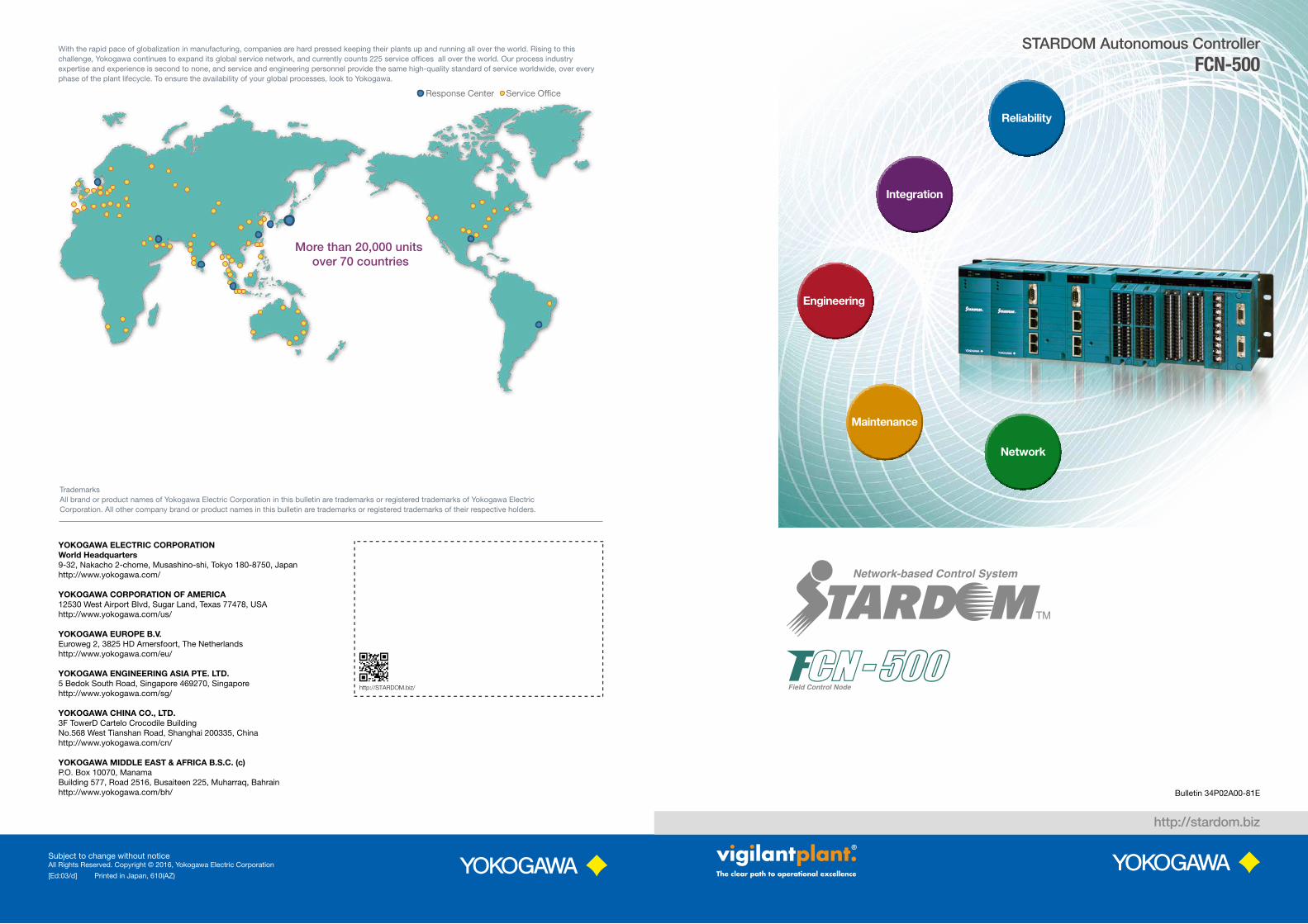
With the rapid pace of globalization in manufacturing, companies are hard pressed keeping their plants up and running all over the world. Rising to this challenge, Yokogawa continues to expand its global service network, and currently counts 225 service of�ces all over the world. Our process industry expertise and experience is second to none, and service and engineering personnel provide the same high-quality standard of service worldwide, over every phase of the plant lifecycle. To ensure the availability of your global processes, look to Yokogawa.
More than 20,000 units over 70 countries
Response Center Service Of�ce
YOKOGAWA ELECTRIC CORPORATIONWorld Headquarters 9-32, Nakacho 2-chome, Musashino-shi, Tokyo 180-8750, Japanhttp://www.yokogawa.com/
YOKOGAWA CORPORATION OF AMERICA 12530 West Airport Blvd, Sugar Land, Texas 77478, USAhttp://www.yokogawa.com/us/
YOKOGAWA EUROPE B.V. Euroweg 2, 3825 HD Amersfoort, The Netherlandshttp://www.yokogawa.com/eu/
YOKOGAWA ENGINEERING ASIA PTE. LTD. 5 Bedok South Road, Singapore 469270, Singaporehttp://www.yokogawa.com/sg/
YOKOGAWA CHINA CO., LTD. 3F TowerD Cartelo Crocodile BuildingNo.568 West Tianshan Road, Shanghai 200335, Chinahttp://www.yokogawa.com/cn/
YOKOGAWA MIDDLE EAST & AFRICA B.S.C. (c)P.O. Box 10070, ManamaBuilding 577, Road 2516, Busaiteen 225, Muharraq, Bahrainhttp://www.yokogawa.com/bh/
TrademarksAll brand or product names of Yokogawa Electric Corporation in this bulletin are trademarks or registered trademarks of Yokogawa ElectricCorporation. All other company brand or product names in this bulletin are trademarks or registered trademarks of their respective holders.
http://STARDOM.biz/
Reliability
Integration
Engineering
Maintenance
Network
STARDOM Autonomous ControllerFCN-500

Maintenance
Engineering
Reliability
Integration
Network
Integration・OPC, DNP3, and Modbus support for use with a variety of SCADA systems・Support of FOUNDATIONTM Fieldbus, HART®, Modbus®, PROFIBUS-DP®, and CANopen® for field device digital communications・ Integrates with several types of networks such as
GPRS and satellite for SCADA communications
Engineering・Support of all five IEC 61131-3 programming languages・Extensive regulatory control libraries cultivated throughout
Yokogawa's DCS history・Target-less debugging for efficient engineering
Reliability・Excellent environmental resistance・Redundant configuration for all key components・ECC memory on durable hardware
Network・TCP/IP-based high speed (1 Gbps) Ethernet port ・Flexible network configuration with a mixture of
redundant and separated networks by selecting 2 or 4 ports model
・Assurance of consistent network security policy with other Yokogawa systems
Maintenance・Hot-swappable modules・Same modules for single and redundant
configurations, and for control and extension units・PC-less maintenance flexibility with SD card operations
The FCN-500 STARDOM controller is a reliable platform that keeps you competitive in a rapidly changing market.・Adapted to complex applications with a high speed CPU and gigabit Ethernet communication・Increased uptime and reduced inventory by use of hot-swappable modules shared between
single and redundant configurations・Reduced engineering and maintenance hours by reuse of program components
Process Control PLC
“FCN-500”strengthens your core competencies
2 3

A TCP/IP-based network enables a seamless connection with control and information networks using
COTS network components, and also allows the easy adaption of controllers for use with narrow
bandwidth network infrastructure including public telephone lines, GSM/GPRS, satellite, and radio.
The use of a redundant network configuration and data buffering guard against the loss of valuable
data in the event of a disruption in network communications.
With gas fields, pipelines, and other SCADA applications, field devices are often dispersed over a
very wide area, and the annual cost of regularly checking these devices is prohibitively high.
By making use of remote device diagnostics, Yokogawa's plant asset management system
enables a much more efficient maintenance approach with dramatic reductions in costs.
Many applications make combined use of DCS and PLC systems. From a single window on the
Yokogawa DCS HMI, operators enjoy seamless and transparent access to all the utilities on these
different systems, with complete consolidation of all alarms.
Integration
One network...but dual redundant One field…spanning hundreds of kilometers
One window...but multiple systems
ModbusPROFIBUS-DP
Alarm and operation
integrations on HIS
Network fail
over features
(YOKOGAWA DCS)
Field WirelessManagement Station
Field WirelessAccess Point
WirelessTransmitters
Modem
Modem
PSTN, xDSL,and more
FCN/FCJ OPCserver for Windows
Other vendor’sSCADA
Yokogawa DCS HMI
HIS
Uni�ed Gateway Station (UGS)
Yokogawa SCADAfor small plant
Yokogawa plant assetmanagement system
Yokogawa plant informationmanagement system
Remote monitoring
Yokogawa SCADA
4 ports modelCPU redundantcon�guration
Yokogawasafety instrumented system
2 ports modelCPU single
con�guration
2 ports modelCPU single
con�guration
4 ports modelCPU redundantcon�guration
Modbus CANopen
HART
FOUNDATION Fieldbus
Remote IO
Field instruments
PLCEngineering
PC
Short base con�guration
Touch panelPLC
Connection Physical layer Devices (protocols)
Upper-level systems
EthernetVDS (TCP/IP), FAST/TOOLS (TCP/IP, DNP3, Modbus TCP), HIS (Vnet/IP via gateway) other vendor SCADA systems (OPC, DNP3, Modbus TCP)
Serial (RS-232, RS-422/485)
FAST/TOOLS (Modbus RTU/ASCII), Other vendor SCADA systems (Modbus RTU/ASCII, DNP3)
Other devicesEthernet FA-M3 (driver available), MELSEC (driver available), others (Modbus TCP)
Serial (RS-232, RS-422/485) FA-M3 (driver available), MELSEC (driver available), others (Modbus RTU/ASCII)
Fieldbus
FOUNDATION Fieldbus FOUNDATION Fieldbus devices
HART HART devices
PROFIBUS-DP PROFIBUS-DP devices
CANopen CANopen devices
ISA100 ISA100 Wireless™ devices (via gateway)
Ethernet Modbus TCP
Serial Modbus RTU/ASCII
Seamless vertical and horizontal integration of the FCN-500 with SCADA, DCS, and field instruments enhances the flexibility of your plant.
▲
Operation and Monitoring
4 5
ReliabilityNetw
orkM
aintenanceEngineering
SpecificationsDim
ensionsSelection Guide
Integration
RAM
Error output
Bit error
CPU
PLCwithout ECC
RAM
CPU
STARDOMcontrollers
ECC
Correct output
Bit error
×
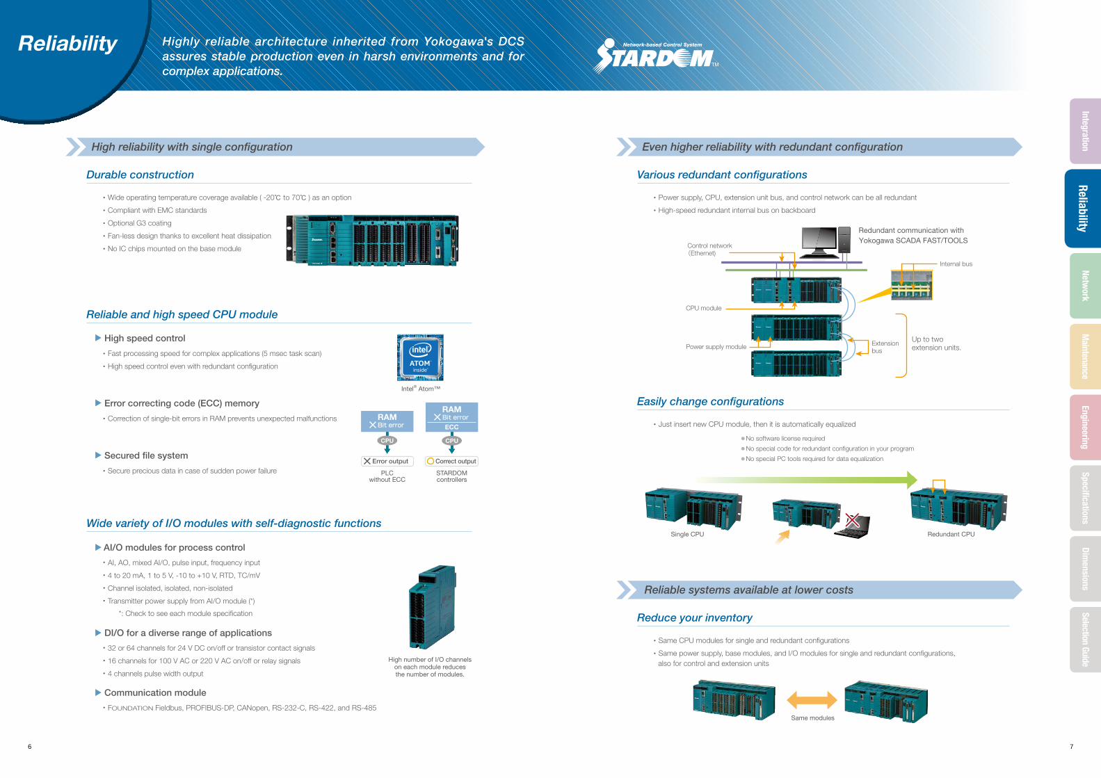
Redundant communication with Yokogawa SCADA FAST/TOOLS
Control network(Ethernet)
CPU module
Power supply module Extensionbus
Internal bus
Up to twoextension units.
Durable construction
・Wide operating temperature coverage available ( -20℃ to 70℃ ) as an option
・Compliant with EMC standards
・Optional G3 coating
・Fan-less design thanks to excellent heat dissipation
・No IC chips mounted on the base module
Reliable and high speed CPU module
▲
High speed control
・Fast processing speed for complex applications (5 msec task scan)
・High speed control even with redundant configuration
▲
Error correcting code (ECC) memory
・Correction of single-bit errors in RAM prevents unexpected malfunctions
▲
Secured file system
・Secure precious data in case of sudden power failure
Various redundant configurations
・Power supply, CPU, extension unit bus, and control network can be all redundant
・High-speed redundant internal bus on backboard
Reduce your inventory
・Same CPU modules for single and redundant configurations
・Same power supply, base modules, and I/O modules for single and redundant configurations, also for control and extension units
Easily change configurations
・Just insert new CPU module, then it is automatically equalized
Wide variety of I/O modules with self-diagnostic functions
▲
AI/O modules for process control
・AI, AO, mixed AI/O, pulse input, frequency input
・4 to 20 mA, 1 to 5 V, -10 to +10 V, RTD, TC/mV
・Channel isolated, isolated, non-isolated
・Transmitter power supply from AI/O module (*)
*: Check to see each module specification
▲
DI/O for a diverse range of applications
・32 or 64 channels for 24 V DC on/off or transistor contact signals
・16 channels for 100 V AC or 220 V AC on/off or relay signals
・4 channels pulse width output
▲
Communication module
・FOUNDATION Fieldbus, PROFIBUS-DP, CANopen, RS-232-C, RS-422, and RS-485
Reliability
High reliability with single configuration Even higher reliability with redundant configuration
Reliable systems available at lower costs
High number of I/O channels on each module reducesthe number of modules.
Single CPU
Intel® Atom™
●No software license required●No special code for redundant configuration in your program●No special PC tools required for data equalization
Highly reliable architecture inherited from Yokogawa's DCS assures stable production even in harsh environments and for complex applications.
Redundant CPU
Same modules
6 7
Network
Maintenance
EngineeringSpecifications
Dimensions
Selection GuideReliability
Integration
Port 1
Port 2
Port 3Port 4Network B
Network A
For maintenance
Redundant control network・Between controller and SCADA・Between controller and controller
PLC
Port 1
Port 2Port 3
Port 4
Network BNetwork A
Network C
Engineering PC
Single control network
PLC
FCN-500
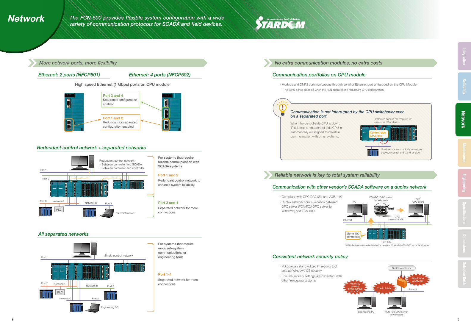
Up to 100controllers
PC
FCN/FCJ OPC server for Windows
PC (*)OPC client
OPCcommunication
*: OPC client software can be installed on the same PC with FCN/FCJ OPC server for Windows.
Ethernet
Attack overa network
Firewall
Business network
Theft of data
Attack bygaining
direct accessto a PC
Engineering PC FCN/FCJ OPC serverfor Windows
Ethernet: 2 ports (NFCP501)
High speed Ethernet (1 Gbps) ports on CPU module
For systems that require reliable communication with SCADA systems
For systems that require more sub-system communications or engineering tools
All separated networks
Redundant control network + separated networks
Ethernet: 4 ports (NFCP502) Communication portfolios on CPU module
・Modbus and DNP3 communications through serial or Ethernet port embedded on the CPU Module*
* The Serial port is disabled when the FCN operates in a redundant CPU configuration.
Communication with other vendor’s SCADA software on a duplex network
・Compliant with OPC DA2.05a and A&E 1.10
・Duplex network communication between OPC server (FCN/FCJ OPC server for Windows) and FCN-500
Consistent network security policy
・Yokogawa’s standardized IT security tool sets up Windows OS security
・Ensures security settings are consistent with other Yokogawa systems
Network
More network ports, more flexibility No extra communication modules, no extra costs
Reliable network is key to total system reliability
When the control-side CPU is down, IP address on the control-side CPU is automatically reassigned to maintain communication with other systems.
Communication is not interrupted by the CPU switchover even on a separated port
Port 3 and 4Separated configuration enabled
Port 1 and 2Redundant or separated configuration enabled
Port 1 and 2Redundant control network to enhance system reliability.
Port 1-4Separated network for more connections.
Port 3 and 4Separated network for more connections.
The FCN-500 provides flexible system configuration with a wide variety of communication protocols for SCADA and field devices.
Dedicated code is not required for switchover IP address.
IP address is automatically reassigned between control and stand-by side.
Control-side CPU fails
8 9
Maintenance
EngineeringSpecifications
Dimensions
Selection GuideReliability
IntegrationNetw
ork

Set to Global Variable in IEC applications.
Web browser
SCADA
System log files on CPU module
・CPU self-diagnosis・I/O diagnosis・Application errors and more…
・System overview・System logs
System status windows on SCADA
LEDs on CPU・System and hardware status ・Task termination (Blinks)
All modules are hot-swappable
▲
Non-stop operation for redundant CPU
・All program copy (APC) synchronizes the control side and stand-by side CPUs without using any PC tools
▲
Quick start after replacing I/O
・ I/O modules can be changed without rewiring
・I/O definitions automatically downloaded to I/O modules without using any PC tools
・Values (fallback function) are output continuously even if the CPU fails
▲
Online battery replacement
・Battery accessible from the front
・Online changeable battery
・Self-diagnostic function detecting lower battery
×Tool
not required
×Tool
not required
Controlling
Download projects
RESET and SHUTDOWN switch
・Save log �les・Backup systems and parameters
・Restore・Revision up
The tuning parameter such as P, I, D on battery-backed up memory area can be also backed up on a SD card.
FUNC SWFunction selection rotary switches
EXEC SWFunction executionpush switch
SD card slot
SD card access status LED
SDcard
SD card access status can be con�rmed even if the cover is locked.
Security slot locking cable
Online download
・No need to stop a controller to modify the control application
・Automatic application synchronization of dual redundant CPUs when downloading with Logic Designer
・Variables inherited from previous applications
PC-less maintenance
・SD card for saving and restoring system information
・Select maintenance operations with the FUNC SW then click the EXEC SW to execute
・Front cover prevents unauthorized access to the systems
・Seal needs to be broken to open the front cover, confirming illegal or unauthorized access
Sealing for site access authentication
Hardware sealing is important to detect unauthorized access.
System information is available locally and remotely
Maintenance
Replacing modules does not interfere with processes Simplified sitemaintenance reduces engineering workload
Higher security for operations on site
・ SD card password can be set on Resource Configurator to prevent illegal access
・ Disable EXEC SW to prevent mis-operation
Simple remote and on-site maintenance procedures reduce maintenance hours and prevent human error.
10 11
EngineeringSpecifications
Dimensions
Selection GuideIntegration
ReliabilityNetw
orkM
aintenance
A platform independent architecture enhances application portability
▲
Logic Designer: Control application development tool
・Platform independent programming tool
・Loop and sequential control with the same development tool
・Intuitive look & feel with automated application layout
・Project comparison function for confirming modifications
▲
Resource Configurator: Hardware configuration tool
・Connects control application logical I/O with actual hardware I/O
・Configures hardware settings for IP addresses, serial ports, etc.
FBD(Function Block Diagram)
LD(Ladder Diagram)
SFC(Sequential Function Chart)
ST(Structured Text)
IL(Instruction List)
ReuseSelect
Insert
Insert
Reuse
Reuse
Reuse
Create
Create
CreateCreate
Typical engineering processUser project
template
User networktemplate
User function blocks
User libraries
Project
Network template
Application portfolios
(FB libraries)
Available from Yokogawa
Your application
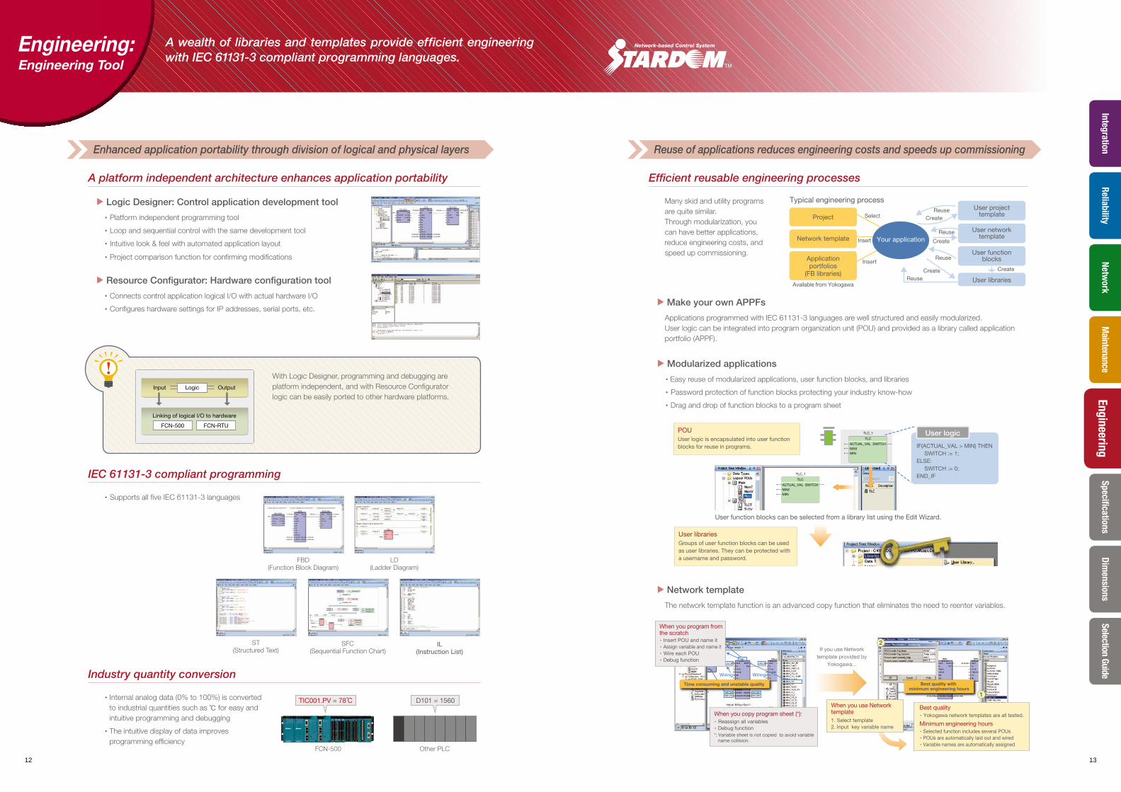
Best quality with minimum engineering hours
If you use Networktemplate provided by
Yokogawa...
Best quality・Yokogawa network templates are all tested.
Minimum engineering hours・Selected function includes several POUs・POUs are automatically laid out and wired・Variable names are automatically assigned
When you copy program sheet (*): ・ Reassign all variables・Debug function*: Variable sheet is not copied to avoid variable name collision.
When you use Network template1. Select template2. Input key variable name
When you program from the scratch・Insert POU and name it・Assign variable and name it・ Wire each POU・Debug function
Wiring Wiring
Time consuming and unstable quality
1
2
TIC001.PV = 78℃ D101 = 1560
▲
Modularized applications
・ Easy reuse of modularized applications, user function blocks, and libraries
・ Password protection of function blocks protecting your industry know-how
・Drag and drop of function blocks to a program sheet
Efficient reusable engineering processes
Many skid and utility programs are quite similar. Through modularization, you can have better applications, reduce engineering costs, and speed up commissioning.
▲
Make your own APPFs
Applications programmed with IEC 61131-3 languages are well structured and easily modularized. User logic can be integrated into program organization unit (POU) and provided as a library called application portfolio (APPF).
▲
Network template
The network template function is an advanced copy function that eliminates the need to reenter variables.
IEC 61131-3 compliant programming
・Supports all five IEC 61131-3 languages
Engineering: Engineering Tool
Enhanced application portability through division of logical and physical layers Reuse of applications reduces engineering costs and speeds up commissioning
With Logic Designer, programming and debugging are platform independent, and with Resource Configurator logic can be easily ported to other hardware platforms.
Linking of logical I/O to hardware
Logic OutputInput
FCN-500 FCN-RTU
A wealth of libraries and templates provide efficient engineering with IEC 61131-3 compliant programming languages.
User librariesGroups of user function blocks can be used as user libraries. They can be protected with a username and password.
User function blocks can be selected from a library list using the Edit Wizard.
IF(ACTUAL_VAL > MIN) THEN SWITCH := 1;ELSE: SWITCH := 0;END_IF
User logicACTUAL_VAL SWITCHMAXMIN
TLC
TLC_1
ACTUAL_VAL SWITCHMAXMIN
TLC
TLC_1
POUUser logic is encapsulated into user function blocks for reuse in programs.
Industry quantity conversion
・ Internal analog data (0% to 100%) is converted to industrial quantities such as ℃ for easy and intuitive programming and debugging
・ The intuitive display of data improves programming efficiency
FCN-500 Other PLC
12 13
SpecificationsDim
ensionsSelection Guide
EngineeringIntegration
ReliabilityNetw
orkM
aintenance
RB_IN CAS_IN
CASVCAS
SVAUTMAN
MAN
CAS/AUT
ROUT
RCASRCASV
Input/Output parameter Access parameter
Alarmprocessing
Inputprocessing
Controlcalculatioins
Outputprocessing OUTMV
RMV
PVIN
TIN INTLOCKBIN
(VN)
RL1
(RLV1)
(CASV)
(RB_OUT)
RL2
(RLV2)
TSI
(TSW)
・・・ process ・・・ Input / Output parameter ・・・ Access parameter
・Input signal conversion ・PV/CPV overshoot・Input open alarm check ・Output signal conversion
・Tight shut/full open
Ethernet
SNTP server SNTP client
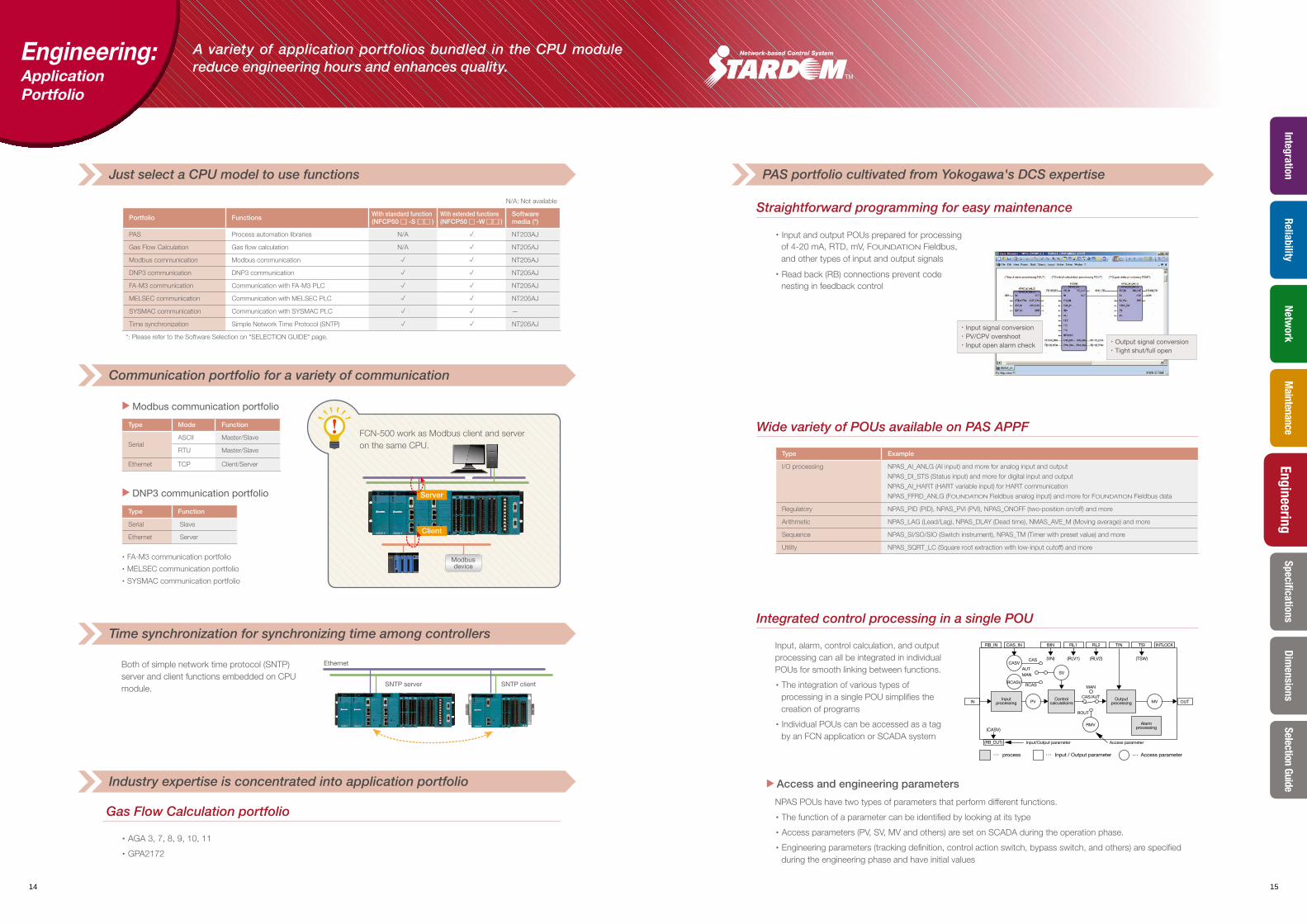
A variety of application portfolios bundled in the CPU module reduce engineering hours and enhances quality.
Straightforward programming for easy maintenance
・Input and output POUs prepared for processing of 4-20 mA, RTD, mV, FOUNDATION Fieldbus, and other types of input and output signals
・Read back (RB) connections prevent code nesting in feedback control
Integrated control processing in a single POU
Input, alarm, control calculation, and output processing can all be integrated in individual POUs for smooth linking between functions.
・The integration of various types of processing in a single POU simplifies the creation of programs
・Individual POUs can be accessed as a tag by an FCN application or SCADA system
▲
Access and engineering parameters
NPAS POUs have two types of parameters that perform different functions.
・The function of a parameter can be identified by looking at its type
・Access parameters (PV, SV, MV and others) are set on SCADA during the operation phase.
・Engineering parameters (tracking definition, control action switch, bypass switch, and others) are specified during the engineering phase and have initial values
Both of simple network time protocol (SNTP) server and client functions embedded on CPU module.
Gas Flow Calculation portfolio
・AGA 3, 7, 8, 9, 10, 11
・GPA2172
Engineering: Application Portfolio
Just select a CPU model to use functions
Communication portfolio for a variety of communication
Time synchronization for synchronizing time among controllers
Industry expertise is concentrated into application portfolio
PAS portfolio cultivated from Yokogawa's DCS expertise
N/A: Not available
Portfolio Functions With standard function(NFCP50□ -S□□ )
With extended functions(NFCP50□ -W□□ )
Software media (*)
PAS Process automation libraries N/A p NT203AJ
Gas Flow Calculation Gas flow calculation N/A p NT205AJ
Modbus communication Modbus communication p p NT205AJ
DNP3 communication DNP3 communication p p NT205AJ
FA-M3 communication Communication with FA-M3 PLC p p NT205AJ
MELSEC communication Communication with MELSEC PLC p p NT205AJ
SYSMAC communication Communication with SYSMAC PLC p p —
Time synchronization Simple Network Time Protocol (SNTP) p p NT205AJ
*: Please refer to the Software Selection on "SELECTION GUIDE" page.
Wide variety of POUs available on PAS APPF
Type Example
I/O processing NPAS_AI_ANLG (AI input) and more for analog input and output
NPAS_DI_STS (Status input) and more for digital input and output
NPAS_AI_HART (HART variable input) for HART communication
NPAS_FFRD_ANLG (FOUNDATION Fieldbus analog input) and more for FOUNDATION Fieldbus data
Regulatory NPAS_PID (PID), NPAS_PVI (PVI), NPAS_ONOFF (two-position on/off) and more
Arithmetic NPAS_LAG (Lead/Lag), NPAS_DLAY (Dead time), NMAS_AVE_M (Moving average) and more
Sequence NPAS_SI/SO/SIO (Switch instrument), NPAS_TM (Timer with preset value) and more
Utility NPAS_SQRT_LC (Square root extraction with low-input cutoff) and more
▲
Modbus communication portfolio
Type Mode Function
SerialASCII Master/Slave
RTU Master/Slave
Ethernet TCP Client/Server
▲
DNP3 communication portfolio
Type Function
Serial Slave
Ethernet Server
・FA-M3 communication portfolio
・MELSEC communication portfolio
・SYSMAC communication portfolio
Server
Client
Modbusdevice
FCN-500 work as Modbus client and server on the same CPU.
14 15
SpecificationsDim
ensionsSelection Guide
EngineeringIntegration
ReliabilityNetw
orkM
aintenance
FAST/TOOLSworkstations
FAST/TOOLSserver 1
SCADA LAN 1SCADA LAN 2
FAST/TOOLSserver 2
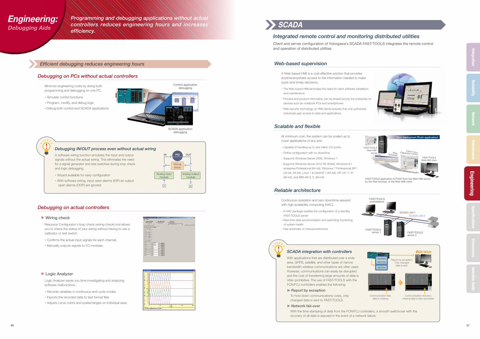
Zero deployment (Push application)
FAST/TOOLSWeb-HMI
server
FAST/TOOLSWeb-HMI client
FAST/TOOLS application is PUSH from the Web-HMI server,by the Web browser, to the Web-HMI client.
SCADAIntegrated remote control and monitoring distributed utilitiesClient and server configuration of Yokogawa's SCADA FAST/TOOLS integrates the remote control and operation of distributed utilities.
Debugging on PCs without actual controllers
Minimize engineering costs by doing both programming and debugging on one PC.
・Simulate control functions
・Program, modify, and debug logic
・Debug both control and SCADA applications
Web-based supervision
A Web-based HMI is a cost effective solution that provides anytime/anywhere access to the information needed to make quick and timely decisions.
・The Web-based HMI eliminates the need for client software installation
and maintenance
・Process and product information can be shared across the enterprise on
devices such as notebook PCs and smartphones
・Web security technology on HMI clients ensures that only authorized
individuals gain access to data and applications
Scalable and flexible
At minimum cost, the system can be scaled up to cover applications of any size.
・Capable of handling up to one million I/O points
・Online configuration with no downtime
・Supports Windows Server 2008, Windows 7
・Supports Windows Server 2012 R2 (64bit), Windows 8.1
enterprise Professional (64-bit), Windows 7 Professional SP1
(32-bit, 64-bit), Linux 7 & CentOS 7 (64-bit), HP-UX 11.31
(64-bit), and IBM AIX 6.1L (64-bit)
Reliable architecture
Continuous operation and zero downtime assured with high availability computing (HAC).
・A HAC package enables the configuration of a standby
FAST/TOOLS server
・Real-time data synchronization and watchdog monitoring
of system health
・Fast automatic or manual switchover
Debugging on actual controllers
▲
Wiring check
Resource Configurator's loop check (wiring check) tool allows you to check the status of your wiring without having to use a calibrator or test switch.
・Confirms the actual input signals for each channel.
・Manually outputs signals to I/O modules.
▲
Logic Analyzer
Logic Analyzer saves you time investigating and analyzing software malfunctions.
・Records variables in continuous and cycle modes
・Exports the recorded data to text format files
・Adjusts curve colors and scales/ranges on individual axes
Engineering: Debugging Aids
Efficient debugging reduces engineering hours
Debugging IN/OUT process even without actual wiring
A software wiring function simulates the input and output signals without the actual wiring. This eliminates the need for a signal generator and test switches during loop check and logic debugging.
・Wizard available for easy configuration
・With software wiring, input open alarms (IOP) an output open alarms (OOP) are ignored
SCADA integration with controllers
With applications that are distributed over a wide area, GPRS, satellite, and other types of narrow bandwidth wireless communications are often used. However, communications can easily be disrupted and the cost of transferring large amounts of data is often prohibitive. The use of FAST/TOOLS with the FCN/FCJ controllers enables the following:
▲
Report by exception To hold down communications costs, only
changed data is sent to FAST/TOOLS.
▲
Network fail-over With the time stamping of data from the FCN/FCJ controllers, a smooth switchover with the
recovery of all data is assured in the event of a network failure.
PIDIN OUT
Wiringblock
Analog outputmodule
Analog inputmodule
Control application debugging
SCADA application debugging
Report by exception:Only changeddata is sent.
Communication fails,data is missing.
Communication recovers,missing data is also recovered.
Val, Time..
Val, Time
Val, Time
Programming and debugging applications without actual controllers reduces engineering hours and increases efficiency.
16 17
SpecificationsDim
ensionsSelection Guide
EngineeringIntegration
ReliabilityNetw
orkM
aintenance

18 19
SpecificationsReliability
IntegrationNetw
orkM
aintenanceEngineering
Dimensions
Selection Guide
SPECIFICATIONS CPU
Items Specification
Model
NFCP501CPU module for FCN(with 2 Ethernet ports)
NFCP502CPU module for FCN(with 4 Ethernet ports)
Processor Atom E3815 1.46GHz
MemoryMain 256MB with ECC
Static RAM 2MB with ECC, backed up by battery
Secondary memory 1GB on-boad flash memory
External media SD card 1 slot : SDHC (4 to 32GB) Class 10
Serial port (*1) 1 RS-232-C port : D-sub 9 pins, male (*2)
Communication Method Full/Half duplex (software settings)
Synchronisation Asynchronous
Baud rate 0.3, 1.2, 2.4, 4.8, 9.6, 14.4, 19.2, 28.8,38.4, 57.6, or 115.2 kbps
Network interface 2 Ethernet ports : RJ45 modular jacks 4 Ethernet ports : RJ45 modular jacks
Baud rate 1000, 100, 10 Mbps, (1000BASE-T, 100BASE-TX, 10BASE-T)
I/O interface SB bus (duplex)
RAS features Watch dog timer, temperature monitor, etc.
Battery (*3) 1000 mAh graphite fluoride lithium battery (*4)
Display3 LEDs for CPU status indication, 2 LEDs for Ethernet status indication,1 LED for SD LED, 1 LED for EXEC LED
Switches RESET switch, SHUT DOWN switch, FUNC switch, EXEC switch
Protection CPU cover (with the hole for wire lock)
Power SupplySupply voltage 5 V DC ± 5%
Current consumption Max. 1200mA Max. 1700mA
Duplex configuration Possible (*5)
Weight 0.9kg
SizeDimensions (W × H × D) 65.8 × 130 × 149.3 mm
Occupying slots 2
*1 : A serial port cannot be used when CPU modules are configured in redundancy.*2 : Connectors are fastended using inch screw threads (No. 4-40 UNC).*3 : With battery exhaustion detection function.*4 : A battery is exchangeable at on-line.*5 : Use a couple of the CPU module of the same type (same Model and same suffix codes) for the CPU module duplex configuration.
Single Configuration(One control unit+2 extension Units)
Long Type
Redundant Configuration(One control unit + 2 extension units)
Short Type
■ Common modules for single and redundant configuration.
■ Common modules for single and extension unit
Occupied slot width2 slots for CPU
1 slot for I/O
FCN CPU SPECIFICATIONS
DMY
Single Configuration(One control unit)
Redundant Configuration(One control unit)
Short Base Configuration(One control unit:extension unit not available)
FCN Configuration (Redundant CPU, Power Supply and SB bus are all enabled)
Guideline of Control Application CapacityAs a guideline, the capacity of the control application is a total of the following:
■ Function blocks (POUs): Up to 512• Regulator control blocks (e.g., indicator blocks, controller
blocks, and manual loaders): Up to 128
• Others (e.g., calculation blocks, switch instrument blocks, and communication POUs): Up to 384
■ Sequence program:Up to 180 Ksteps in Ladder or up to 128 sequence tables each of which has 32 condition and 32 action rows.
Network (Ethernet) Specifications
■ Communicate with up to 15 FCN/FCJ per FCN ■ Communicate with up to 4 upper systems (*1) per FCN
*1 : Total number of VDS, FCN/FCJ OPC Server and FAST/TOOLS.
Common CPU Specifications
TASK EXECUTION
Excecution speed: Approx. 10 μ per Ksteps in an IL program
Number of Control Applications: Max. 16 tasks
Task priority: Can be specifiled (in 16 levels)
Task Execution Cycle: 5 msec or longer (by 5 msec. increments) (*1)
Control Application capacity: Max. 3MB (approx. 400 Ksteps in an IL program)
Data Area (*2): Max. 8MB
Retained Data Area (*3): Max. 700KB
*1 : When using the I/O module, task exectution cycle is recommended more than 20 msec.
*2 : The data is not retained when the power is off.*3 : The data is retained even if the power is off. The data is retained during
a power failure (can be used to store tuning parameter settings for the control application).
CPU MEMORY CAPACITY
CPU Function Specification
Abbr. Description Redundant
PWM Power supply module p
CPU CPU module p
IOM I/O module N/A
NFSB SB bus repeat module p
DMY Dummy cover -
Maximum numbers of I/O modulesBase Module Unit Configuration Standard Configuration Redundant (*1) Configuration
Base Module (NFBU200)
Control unit only Max. 8 Max. 6
With one extension unit (*2) Max. 16 Max. 12
With two extension units (*2) Max. 25 Max. 20
Base Module (NFBU050) Control unit only Max. 3 N/A
*1: When CPU and SB bus repeat modules are duplexed.*2: Wider temperature range is not available for the extension unit.
20 21
SpecificationsReliability
IntegrationNetw
orkM
aintenanceEngineering
Dimensions
Selection Guide
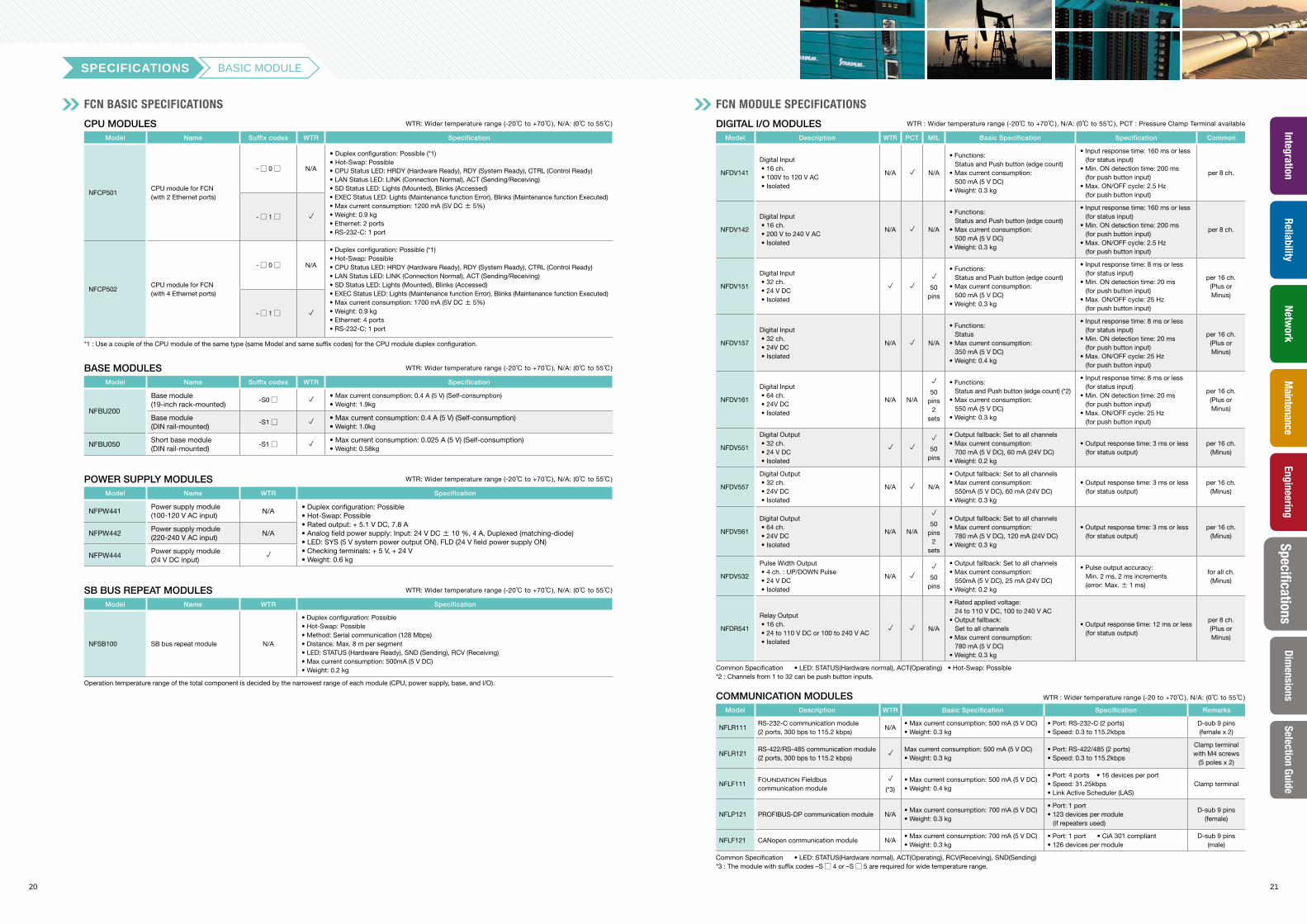
SPECIFICATIONS BASIC MODULE
CPU MODULES WTR: Wider temperature range (-20℃ to +70℃), N/A: (0℃ to 55℃)
Model Name Suffix codes WTR Specification
NFCP501CPU module for FCN(with 2 Ethernet ports)
-□ 0□ N/A
• Duplex configuration: Possible (*1)• Hot-Swap: Possible• CPU Status LED: HRDY (Hardware Ready), RDY (System Ready), CTRL (Control Ready)• LAN Status LED: LINK (Connection Normal), ACT (Sending/Receiving)• SD Status LED: Lights (Mounted), Blinks (Accessed)• EXEC Status LED: Lights (Maintenance function Error), Blinks (Maintenance function Executed)• Max current consumption: 1200 mA (5V DC ± 5%)• Weight: 0.9 kg• Ethernet: 2 ports• RS-232-C: 1 port
-□ 1□ p
NFCP502CPU module for FCN(with 4 Ethernet ports)
-□ 0□ N/A
• Duplex configuration: Possible (*1)• Hot-Swap: Possible• CPU Status LED: HRDY (Hardware Ready), RDY (System Ready), CTRL (Control Ready)• LAN Status LED: LINK (Connection Normal), ACT (Sending/Receiving)• SD Status LED: Lights (Mounted), Blinks (Accessed)• EXEC Status LED: Lights (Maintenance function Error), Blinks (Maintenance function Executed)• Max current consumption: 1700 mA (5V DC ± 5%)• Weight: 0.9 kg• Ethernet: 4 ports• RS-232-C: 1 port
-□ 1□ p
*1 : Use a couple of the CPU module of the same type (same Model and same suffix codes) for the CPU module duplex configuration.
BASE MODULES WTR: Wider temperature range (-20℃ to +70℃), N/A: (0℃ to 55℃)
Model Name Suffix codes WTR Specification
NFBU200
Base module(19-inch rack-mounted)
-S0□ p • Max current consumption: 0.4 A (5 V) (Self-consumption)• Weight: 1.9kg
Base module(DIN rail-mounted)
-S1□ p • Max current consumption: 0.4 A (5 V) (Self-consumption)• Weight: 1.0kg
NFBU050Short base module(DIN rail-mounted)
-S1□ p • Max current consumption: 0.025 A (5 V) (Self-consumption) • Weight: 0.58kg
POWER SUPPLY MODULES WTR: Wider temperature range (-20℃ to +70℃), N/A: (0℃ to 55℃)
Model Name WTR Specification
NFPW441Power supply module(100-120 V AC input)
N/A• Duplex configuration: Possible• Hot-Swap: Possible• Rated output: + 5.1 V DC, 7.8 A• Analog field power supply: Input: 24 V DC ± 10 %, 4 A, Duplexed (matching-diode)• LED: SYS (5 V system power output ON), FLD (24 V field power supply ON)• Checking terminals: + 5 V, + 24 V• Weight: 0.6 kg
NFPW442Power supply module(220-240 V AC input)
N/A
NFPW444Power supply module(24 V DC input)
p
SB BUS REPEAT MODULES WTR: Wider temperature range (-20℃ to +70℃), N/A: (0℃ to 55℃)
Model Name WTR Specification
NFSB100 SB bus repeat module N/A
• Duplex configuration: Possible • Hot-Swap: Possible• Method: Serial communication (128 Mbps) • Distance: Max. 8 m per segment• LED: STATUS (Hardware Ready), SND (Sending), RCV (Receiving)• Max current consumption: 500mA (5 V DC)• Weight: 0.2 kg
Operation temperature range of the total component is decided by the narrowest range of each module (CPU, power supply, base, and I/O).
DIGITAL I/O MODULES WTR : Wider temperature range (-20℃ to +70℃), N/A: (0℃ to 55℃), PCT : Pressure Clamp Terminal available
Model Description WTR PCT MIL Basic Specification Specification Common
NFDV141
Digital Input • 16 ch. • 100V to 120 V AC • Isolated
N/A p N/A
• Functions: Status and Push button (edge count)• Max current consumption: 500 mA (5 V DC)• Weight: 0.3 kg
• Input response time: 160 ms or less (for status input)• Min. ON detection time: 200 ms (for push button input)• Max. ON/OFF cycle: 2.5 Hz (for push button input)
per 8 ch.
NFDV142
Digital Input • 16 ch. • 200 V to 240 V AC • Isolated
N/A p N/A
• Functions: Status and Push button (edge count)• Max current consumption: 500 mA (5 V DC)• Weight: 0.3 kg
• Input response time: 160 ms or less (for status input)• Min. ON detection time: 200 ms (for push button input)• Max. ON/OFF cycle: 2.5 Hz (for push button input)
per 8 ch.
NFDV151
Digital Input • 32 ch. • 24 V DC • Isolated
p p
p
50 pins
• Functions: Status and Push button (edge count)• Max current consumption: 500 mA (5 V DC)• Weight: 0.3 kg
• Input response time: 8 ms or less (for status input)• Min. ON detection time: 20 ms (for push button input)• Max. ON/OFF cycle: 25 Hz (for push button input)
per 16 ch.(Plus or Minus)
NFDV157
Digital Input • 32 ch. • 24V DC • Isolated
N/A p N/A
• Functions: Status• Max current consumption: 350 mA (5 V DC)• Weight: 0.4 kg
• Input response time: 8 ms or less (for status input)• Min. ON detection time: 20 ms (for push button input)• Max. ON/OFF cycle: 25 Hz (for push button input)
per 16 ch.(Plus or Minus)
NFDV161
Digital Input • 64 ch. • 24V DC • Isolated
N/A N/A
p
50 pins
2 sets
• Functions: Status and Push button (edge count) (*2)• Max current consumption: 550 mA (5 V DC)• Weight: 0.3 kg
• Input response time: 8 ms or less (for status input)• Min. ON detection time: 20 ms (for push button input)• Max. ON/OFF cycle: 25 Hz (for push button input)
per 16 ch.(Plus or Minus)
NFDV551
Digital Output • 32 ch. • 24 V DC • Isolated
p p
p
50 pins
• Output fallback: Set to all channels • Max current consumption: 700 mA (5 V DC), 60 mA (24V DC)• Weight: 0.2 kg
• Output response time: 3 ms or less (for status output)
per 16 ch.(Minus)
NFDV557
Digital Output • 32 ch. • 24V DC • Isolated
N/A p N/A
• Output fallback: Set to all channels • Max current consumption: 550mA (5 V DC), 60 mA (24V DC)• Weight: 0.3 kg
• Output response time: 3 ms or less (for status output)
per 16 ch.(Minus)
NFDV561
Digital Output • 64 ch. • 24V DC • Isolated
N/A N/A
p
50 pins
2 sets
• Output fallback: Set to all channels • Max current consumption: 780 mA (5 V DC), 120 mA (24V DC)• Weight: 0.3 kg
• Output response time: 3 ms or less (for status output)
per 16 ch.(Minus)
NFDV532
Pulse Width Output • 4 ch. : UP/DOWN Pulse • 24 V DC • Isolated
N/A p
p
50 pins
• Output fallback: Set to all channels • Max current consumption: 550mA (5 V DC), 25 mA (24V DC)• Weight: 0.2 kg
• Pulse output accuracy: Min. 2 ms, 2 ms increments (error: Max. ± 1 ms)
for all ch.(Minus)
NFDR541
Relay Output • 16 ch. • 24 to 110 V DC or 100 to 240 V AC • Isolated
p p N/A
• Rated applied voltage: 24 to 110 V DC, 100 to 240 V AC• Output fallback: Set to all channels • Max current consumption: 780 mA (5 V DC)• Weight: 0.3 kg
• Output response time: 12 ms or less (for status output)
per 8 ch.(Plus or Minus)
Common Specification • LED: STATUS(Hardware normal), ACT(Operating) • Hot-Swap: Possible*2 : Channels from 1 to 32 can be push button inputs.
COMMUNICATION MODULES WTR : Wider temperature range (-20 to +70℃), N/A: (0℃ to 55℃)
Model Description WTR Basic Specification Specification Remarks
NFLR111RS-232-C communication module (2 ports, 300 bps to 115.2 kbps)
N/A• Max current consumption: 500 mA (5 V DC)• Weight: 0.3 kg
• Port: RS-232-C (2 ports) • Speed: 0.3 to 115.2kbps
D-sub 9 pins(female x 2)
NFLR121RS-422/RS-485 communication module (2 ports, 300 bps to 115.2 kbps)
pMax current consumption: 500 mA (5 V DC)• Weight: 0.3 kg
• Port: RS-422/485 (2 ports)• Speed: 0.3 to 115.2kbps
Clamp terminal with M4 screws
(5 poles x 2)
NFLF111FOUNDATION Fieldbus communication module
p
(*3)
• Max current consumption: 500 mA (5 V DC)• Weight: 0.4 kg
• Port: 4 ports • 16 devices per port• Speed: 31.25kbps• Link Active Scheduler (LAS)
Clamp terminal
NFLP121 PROFIBUS-DP communication module N/A• Max current consumption: 700 mA (5 V DC)• Weight: 0.3 kg
• Port: 1 port• 123 devices per module (if repeaters used)
D-sub 9 pins(female)
NFLF121 CANopen communication module N/A• Max current consumption: 700 mA (5 V DC)• Weight: 0.3 kg
• Port: 1 port • CiA 301 compliant• 126 devices per module
D-sub 9 pins(male)
Common Specification • LED: STATUS(Hardware normal), ACT(Operating), RCV(Receiving), SND(Sending) *3 : The module with suffix codes –S□ 4 or –S□ 5 are required for wide temperature range.
FCN BASIC SPECIFICATIONS FCN MODULE SPECIFICATIONS
22 23
SpecificationsReliability
IntegrationNetw
orkM
aintenanceEngineering
Dimensions
Selection Guide
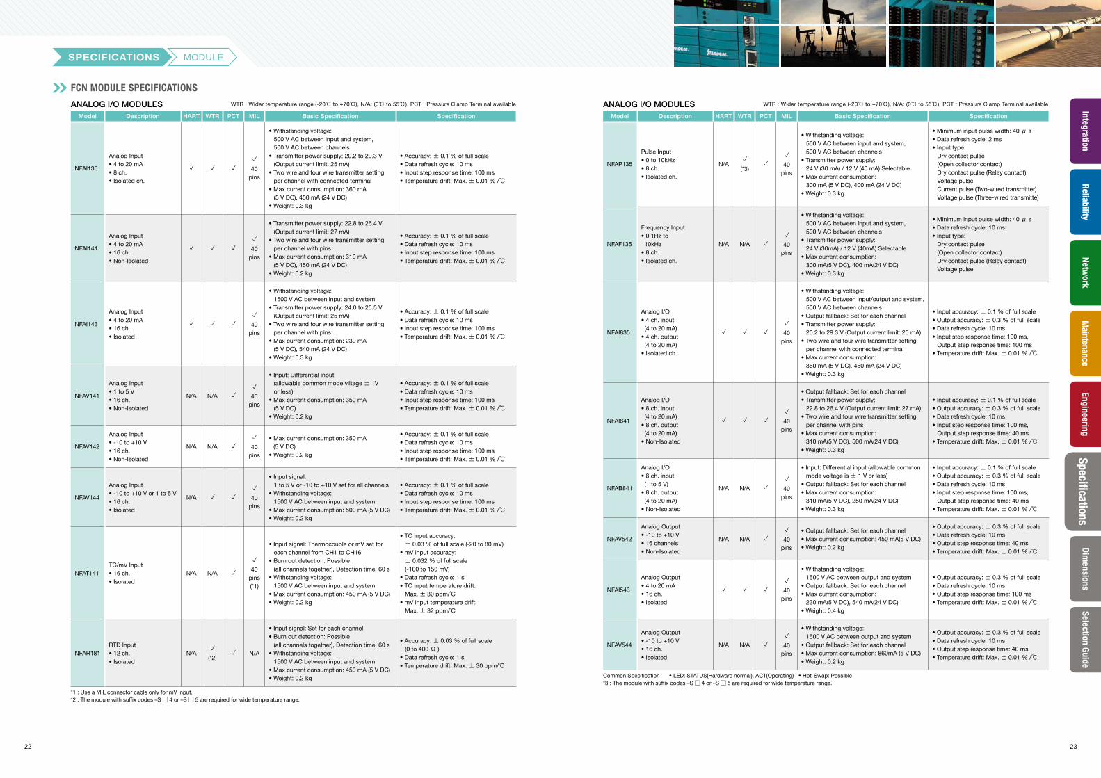
SPECIFICATIONS MODULE
FCN MODULE SPECIFICATIONS
ANALOG I/O MODULES WTR : Wider temperature range (-20℃ to +70℃), N/A: (0℃ to 55℃), PCT : Pressure Clamp Terminal available
Model Description HART WTR PCT MIL Basic Specification Specification
NFAI135
Analog Input• 4 to 20 mA• 8 ch. • Isolated ch.
p p p
p
40 pins
• Withstanding voltage: 500 V AC between input and system, 500 V AC between channels• Transmitter power supply: 20.2 to 29.3 V (Output current limit: 25 mA)• Two wire and four wire transmitter setting per channel with connected terminal• Max current consumption: 360 mA (5 V DC), 450 mA (24 V DC)• Weight: 0.3 kg
• Accuracy: ± 0.1 % of full scale• Data refresh cycle: 10 ms• Input step response time: 100 ms• Temperature drift: Max. ± 0.01 % /℃
NFAI141
Analog Input• 4 to 20 mA• 16 ch.• Non-Isolated
p p p
p
40 pins
• Transmitter power supply: 22.8 to 26.4 V (Output current limit: 27 mA)• Two wire and four wire transmitter setting per channel with pins• Max current consumption: 310 mA (5 V DC), 450 mA (24 V DC)• Weight: 0.2 kg
• Accuracy: ± 0.1 % of full scale• Data refresh cycle: 10 ms• Input step response time: 100 ms• Temperature drift: Max. ± 0.01 % /℃
NFAI143
Analog Input• 4 to 20 mA• 16 ch.• Isolated
p p p
p
40 pins
• Withstanding voltage: 1500 V AC between input and system• Transmitter power supply: 24.0 to 25.5 V (Output current limit: 25 mA)• Two wire and four wire transmitter setting per channel with pins• Max current consumption: 230 mA (5 V DC), 540 mA (24 V DC)• Weight: 0.3 kg
• Accuracy: ± 0.1 % of full scale• Data refresh cycle: 10 ms• Input step response time: 100 ms• Temperature drift: Max. ± 0.01 % /℃
NFAV141
Analog Input• 1 to 5 V• 16 ch.• Non-Isolated
N/A N/A p
p
40 pins
• Input: Differential input (allowable common mode viltage ± 1V
or less)• Max current consumption: 350 mA (5 V DC)• Weight: 0.2 kg
• Accuracy: ± 0.1 % of full scale• Data refresh cycle: 10 ms• Input step response time: 100 ms• Temperature drift: Max. ± 0.01 % /℃
NFAV142
Analog Input• -10 to +10 V• 16 ch.• Non-Isolated
N/A N/A p
p
40 pins
• Max current consumption: 350 mA (5 V DC)
• Weight: 0.2 kg
• Accuracy: ± 0.1 % of full scale• Data refresh cycle: 10 ms• Input step response time: 100 ms• Temperature drift: Max. ± 0.01 % /℃
NFAV144
Analog Input• -10 to +10 V or 1 to 5 V• 16 ch.• Isolated
N/A p p
p
40 pins
• Input signal: 1 to 5 V or -10 to +10 V set for all channels• Withstanding voltage: 1500 V AC between input and system• Max current consumption: 500 mA (5 V DC)• Weight: 0.2 kg
• Accuracy: ± 0.1 % of full scale• Data refresh cycle: 10 ms• Input step response time: 100 ms• Temperature drift: Max. ± 0.01 % /℃
NFAT141TC/mV Input• 16 ch.• Isolated
N/A N/A p
p
40 pins(*1)
• Input signal: Thermocouple or mV set for each channel from CH1 to CH16• Burn out detection: Possible (all channels together), Detection time: 60 s• Withstanding voltage: 1500 V AC between input and system• Max current consumption: 450 mA (5 V DC)• Weight: 0.2 kg
• TC input accuracy: ± 0.03 % of full scale (-20 to 80 mV)• mV input accuracy: ± 0.032 % of full scale
(-100 to 150 mV)• Data refresh cycle: 1 s• TC input temperature drift: Max.± 30 ppm/℃• mV input temperature drift: Max.± 32 ppm/℃
NFAR181RTD Input• 12 ch.• Isolated
N/Ap
(*2)p N/A
• Input signal: Set for each channel• Burn out detection: Possible (all channels together), Detection time: 60 s• Withstanding voltage: 1500 V AC between input and system• Max current consumption: 450 mA (5 V DC)• Weight: 0.2 kg
• Accuracy: ± 0.03 % of full scale (0 to 400 Ω )• Data refresh cycle: 1 s• Temperature drift: Max. ± 30 ppm/℃
*1 : Use a MIL connector cable only for mV input.*2 : The module with suffix codes –S□ 4 or –S□ 5 are required for wide temperature range.
ANALOG I/O MODULES WTR : Wider temperature range (-20℃ to +70℃), N/A: (0℃ to 55℃), PCT : Pressure Clamp Terminal available
Model Description HART WTR PCT MIL Basic Specification Specification
NFAP135
Pulse Input• 0 to 10kHz• 8 ch.• Isolated ch.
N/Ap
(*3)p
p
40 pins
• Withstanding voltage: 500 V AC between input and system, 500 V AC between channels• Transmitter power supply: 24 V (30 mA) / 12 V (40 mA) Selectable• Max current consumption: 300 mA (5 V DC), 400 mA (24 V DC)• Weight: 0.3 kg
• Minimum input pulse width: 40μ s• Data refresh cycle: 2 ms• Input type: Dry contact pulse
(Open collector contact) Dry contact pulse (Relay contact) Voltage pulse Current pulse (Two-wired transmitter) Voltage pulse (Three-wired transmitte)
NFAF135
Frequency Input• 0.1Hz to 10kHz• 8 ch.• Isolated ch.
N/A N/A p
p
40 pins
• Withstanding voltage: 500 V AC between input and system, 500 V AC between channels• Transmitter power supply: 24 V (30mA) / 12 V (40mA) Selectable• Max current consumption: 300 mA(5 V DC), 400 mA(24 V DC)• Weight: 0.3 kg
• Minimum input pulse width: 40μ s• Data refresh cycle: 10 ms• Input type: Dry contact pulse
(Open collector contact) Dry contact pulse (Relay contact) Voltage pulse
NFAI835
Analog I/O• 4 ch. input (4 to 20 mA) • 4 ch. output (4 to 20 mA)• Isolated ch.
p p p
p
40 pins
• Withstanding voltage: 500 V AC between input/output and system,
500 V AC between channels• Output fallback: Set for each channel• Transmitter power supply: 20.2 to 29.3 V (Output current limit: 25 mA)• Two wire and four wire transmitter setting per channel with connected terminal• Max current consumption: 360 mA (5 V DC), 450 mA (24 V DC)• Weight: 0.3 kg
• Input accuracy: ± 0.1 % of full scale• Output accuracy: ± 0.3 % of full scale• Data refresh cycle: 10 ms• Input step response time: 100 ms, Output step response time: 100 ms• Temperature drift: Max. ± 0.01 % /℃
NFAI841
Analog I/O• 8 ch. input (4 to 20 mA) • 8 ch. output (4 to 20 mA)• Non-Isolated
p p p
p
40 pins
• Output fallback: Set for each channel• Transmitter power supply: 22.8 to 26.4 V (Output current limit: 27 mA)• Two wire and four wire transmitter setting per channel with pins• Max current consumption: 310 mA(5 V DC), 500 mA(24 V DC)• Weight: 0.3 kg
• Input accuracy: ± 0.1 % of full scale• Output accuracy: ± 0.3 % of full scale• Data refresh cycle: 10 ms• Input step response time: 100 ms, Output step response time: 40 ms• Temperature drift: Max. ± 0.01 % /℃
NFAB841
Analog I/O• 8 ch. input (1 to 5 V) • 8 ch. output (4 to 20 mA)• Non-Isolated
N/A N/A p
p
40 pins
• Input: Differential input (allowable common mode voltage is ± 1 V or less)• Output fallback: Set for each channel• Max current consumption: 310 mA(5 V DC), 250 mA(24 V DC)• Weight: 0.3 kg
• Input accuracy: ± 0.1 % of full scale• Output accuracy: ± 0.3 % of full scale• Data refresh cycle: 10 ms• Input step response time: 100 ms, Output step response time: 40 ms• Temperature drift: Max. ± 0.01 % /℃
NFAV542
Analog Output• -10 to +10 V• 16 channels• Non-Isolated
N/A N/A p
p
40 pins
• Output fallback: Set for each channel• Max current consumption: 450 mA(5 V DC)• Weight: 0.2 kg
• Output accuracy: ± 0.3 % of full scale• Data refresh cycle: 10 ms• Output step response time: 40 ms• Temperature drift: Max. ± 0.01 % /℃
NFAI543
Analog Output• 4 to 20 mA• 16 ch.• Isolated
p p p
p
40 pins
• Withstanding voltage: 1500 V AC between output and system• Output fallback: Set for each channel• Max current consumption: 230 mA(5 V DC), 540 mA(24 V DC)• Weight: 0.4 kg
• Output accuracy: ± 0.3 % of full scale• Data refresh cycle: 10 ms• Output step response time: 100 ms• Temperature drift: Max. ± 0.01 % /℃
NFAV544
Analog Output• -10 to +10 V • 16 ch.• Isolated
N/A N/A p
p
40 pins
• Withstanding voltage: 1500 V AC between output and system• Output fallback: Set for each channel• Max current consumption: 860mA (5 V DC)• Weight: 0.2 kg
• Output accuracy: ± 0.3 % of full scale• Data refresh cycle: 10 ms• Output step response time: 40 ms• Temperature drift: Max. ± 0.01 % /℃
Common Specification • LED: STATUS(Hardware normal), ACT(Operating) • Hot-Swap: Possible*3 : The module with suffix codes –S□ 4 or –S□ 5 are required for wide temperature range.
24 25
ReliabilityIntegration
Network
Maintenance
EngineeringSelection Guide
Dimensions
Specifications
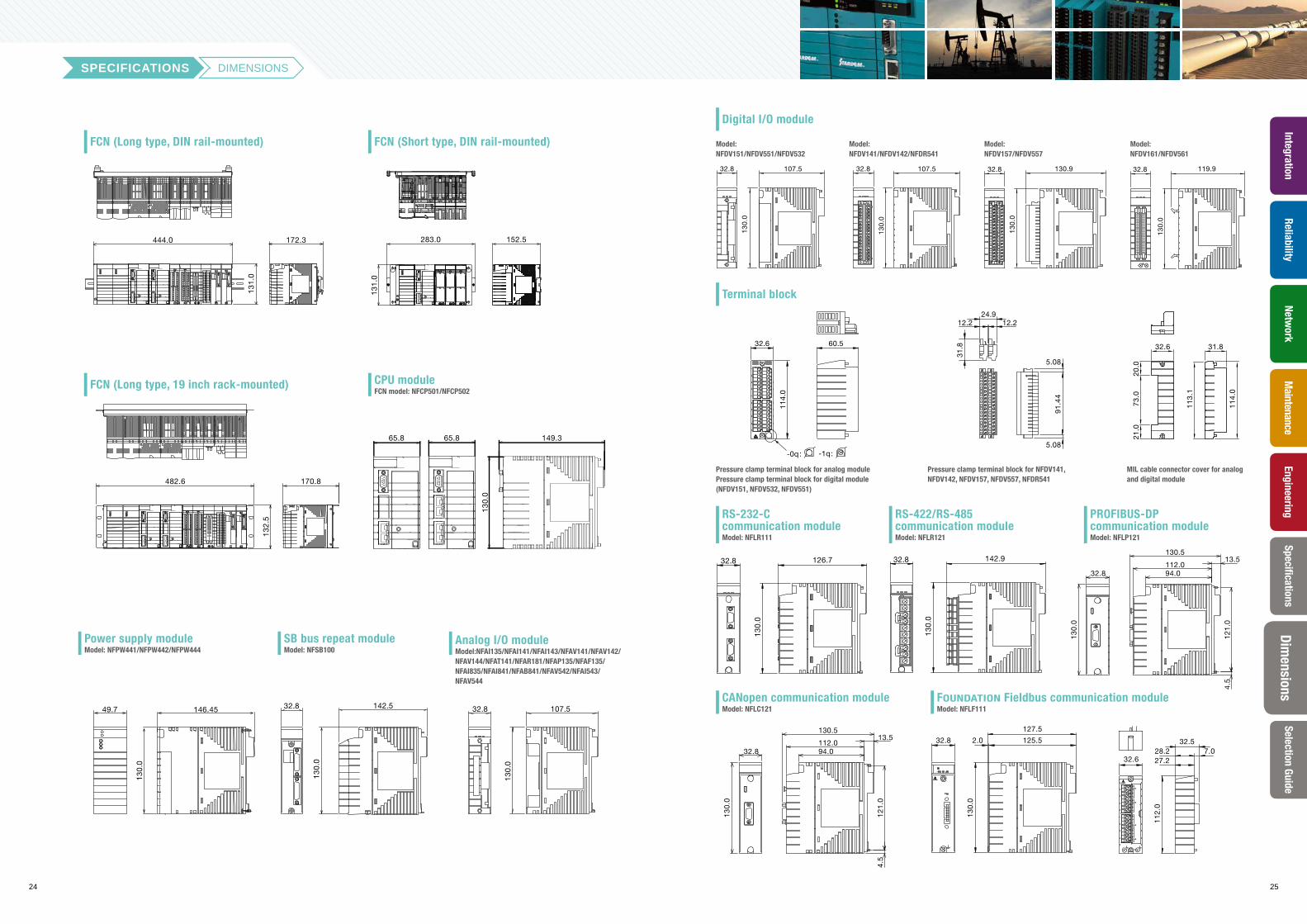
SPECIFICATIONS DIMENSIONS
283.0 152.5
131.
0
444.013
1.0
172.3
FCN (Long type, DIN rail-mounted)
107.532.8
130.
0
Model: NFDV151/NFDV551/NFDV532
107.5
130.
0
32.8
Model: NFDV141/NFDV142/NFDR541
130.932.8
130.
0
Model: NFDV157/NFDV557
119.9
130.
0
32.8
Model: NFDV161/NFDV561
Digital I/O module
130.5
32.8
130.
0
112.013.5
94.0
4.5
121.
0
CANopen communication moduleModel: NFLC121
127.5
125.52.032.8
130.
0
CH1
CH2
CH3
CH4
32.57.028.2
27.232.6
112.
0
FOUNDATION Fieldbus communication moduleModel: NFLF111
32.8 126.7
130.
0
RS-232-C communication moduleModel: NFLR111
32.8 142.9
130.
0
RS-422/RS-485 communication moduleModel: NFLR121
130.5
32.8
130.
0
112.013.5
94.0
4.5
121.
0
PROFIBUS-DP communication moduleModel: NFLP121
60.532.6
114.
0
-0q : -1q:
Pressure clamp terminal block for analog module Pressure clamp terminal block for digital module (NFDV151, NFDV532, NFDV551)
12.2 12.2
5.08
91.4
4
24.9
5.08
31.8
Pressure clamp terminal block for NFDV141, NFDV142, NFDV157, NFDV557, NFDR541
31.832.6
73.0
21.0
20.0
113.
1
114.
0
MIL cable connector cover for analog and digital module
Terminal block
146.45
130.
0
49.7 142.532.8
130.
0
107.532.8
130.
0
Power supply moduleModel: NFPW441/NFPW442/NFPW444
SB bus repeat moduleModel: NFSB100
Analog I/O moduleModel:NFAI135/NFAI141/NFAI143/NFAV141/NFAV142/NFAV144/NFAT141/NFAR181/NFAP135/NFAF135/NFAI835/NFAI841/NFAB841/NFAV542/NFAI543/NFAV544
FCN (Short type, DIN rail-mounted)
482.6 170.8
132.
5
149.3
130.
0
65.865.8
FCN (Long type, 19 inch rack-mounted) CPU moduleFCN model: NFCP501/NFCP502
26 27
ReliabilityIntegration
Network
Maintenance
EngineeringDim
ensionsSpecifications
Selection Guide
Name Model Suffix Codes/Options Codes
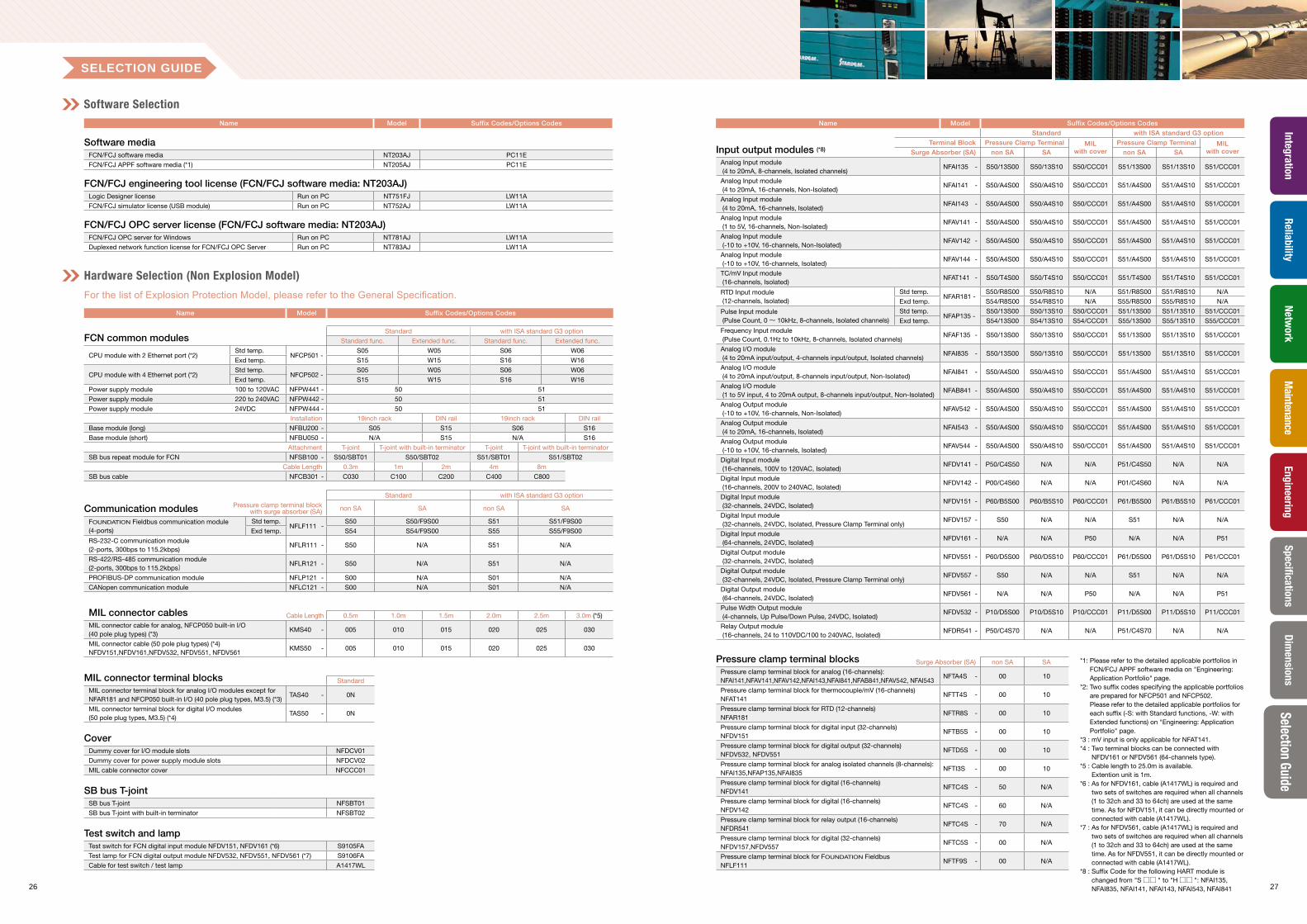
Input output modules (*8)
Standard with ISA standard G3 option
Terminal Block Pressure Clamp Terminal MIL with cover
Pressure Clamp Terminal MIL with coverSurge Absorber (SA) non SA SA non SA SA
Analog Input module (4 to 20mA, 8-channels, Isolated channels)
NFAI135 - S50/13S00 S50/13S10 S50/CCC01 S51/13S00 S51/13S10 S51/CCC01
Analog Input module (4 to 20mA, 16-channels, Non-Isolated)
NFAI141 - S50/A4S00 S50/A4S10 S50/CCC01 S51/A4S00 S51/A4S10 S51/CCC01
Analog Input module (4 to 20mA, 16-channels, Isolated)
NFAI143 - S50/A4S00 S50/A4S10 S50/CCC01 S51/A4S00 S51/A4S10 S51/CCC01
Analog Input module (1 to 5V, 16-channels, Non-Isolated)
NFAV141 - S50/A4S00 S50/A4S10 S50/CCC01 S51/A4S00 S51/A4S10 S51/CCC01
Analog Input module (-10 to +10V, 16-channels, Non-Isolated)
NFAV142 - S50/A4S00 S50/A4S10 S50/CCC01 S51/A4S00 S51/A4S10 S51/CCC01
Analog Input module (-10 to +10V, 16-channels, Isolated)
NFAV144 - S50/A4S00 S50/A4S10 S50/CCC01 S51/A4S00 S51/A4S10 S51/CCC01
TC/mV Input module (16-channels, Isolated)
NFAT141 - S50/T4S00 S50/T4S10 S50/CCC01 S51/T4S00 S51/T4S10 S51/CCC01
RTD Input module (12-channels, Isolated)
Std temp.NFAR181 -
S50/R8S00 S50/R8S10 N/A S51/R8S00 S51/R8S10 N/A
Exd temp. S54/R8S00 S54/R8S10 N/A S55/R8S00 S55/R8S10 N/A
Pulse Input module (Pulse Count, 0~ 10kHz, 8-channels, Isolated channels)
Std temp.NFAP135 -
S50/13S00 S50/13S10 S50/CCC01 S51/13S00 S51/13S10 S51/CCC01
Exd temp. S54/13S00 S54/13S10 S54/CCC01 S55/13S00 S55/13S10 S55/CCC01
Frequency Input module (Pulse Count, 0.1Hz to 10kHz, 8-channels, Isolated channels)
NFAF135 - S50/13S00 S50/13S10 S50/CCC01 S51/13S00 S51/13S10 S51/CCC01
Analog I/O module (4 to 20mA input/output, 4-channels input/output, Isolated channels)
NFAI835 - S50/13S00 S50/13S10 S50/CCC01 S51/13S00 S51/13S10 S51/CCC01
Analog I/O module (4 to 20mA input/output, 8-channels input/output, Non-Isolated)
NFAI841 - S50/A4S00 S50/A4S10 S50/CCC01 S51/A4S00 S51/A4S10 S51/CCC01
Analog I/O module (1 to 5V input, 4 to 20mA output, 8-channels input/output, Non-Isolated)
NFAB841 - S50/A4S00 S50/A4S10 S50/CCC01 S51/A4S00 S51/A4S10 S51/CCC01
Analog Output module (-10 to +10V, 16-channels, Non-Isolated)
NFAV542 - S50/A4S00 S50/A4S10 S50/CCC01 S51/A4S00 S51/A4S10 S51/CCC01
Analog Output module (4 to 20mA, 16-channels, Isolated)
NFAI543 - S50/A4S00 S50/A4S10 S50/CCC01 S51/A4S00 S51/A4S10 S51/CCC01
Analog Output module (-10 to +10V, 16-channels, Isolated)
NFAV544 - S50/A4S00 S50/A4S10 S50/CCC01 S51/A4S00 S51/A4S10 S51/CCC01
Digital Input module (16-channels, 100V to 120VAC, Isolated)
NFDV141 - P50/C4S50 N/A N/A P51/C4S50 N/A N/A
Digital Input module (16-channels, 200V to 240VAC, Isolated)
NFDV142 - P00/C4S60 N/A N/A P01/C4S60 N/A N/A
Digital Input module (32-channels, 24VDC, Isolated)
NFDV151 - P60/B5S00 P60/B5S10 P60/CCC01 P61/B5S00 P61/B5S10 P61/CCC01
Digital Input module (32-channels, 24VDC, Isolated, Pressure Clamp Terminal only)
NFDV157 - S50 N/A N/A S51 N/A N/A
Digital Input module (64-channels, 24VDC, Isolated)
NFDV161 - N/A N/A P50 N/A N/A P51
Digital Output module (32-channels, 24VDC, Isolated)
NFDV551 - P60/D5S00 P60/D5S10 P60/CCC01 P61/D5S00 P61/D5S10 P61/CCC01
Digital Output module (32-channels, 24VDC, Isolated, Pressure Clamp Terminal only)
NFDV557 - S50 N/A N/A S51 N/A N/A
Digital Output module (64-channels, 24VDC, Isolated)
NFDV561 - N/A N/A P50 N/A N/A P51
Pulse Width Output module (4-channels, Up Pulse/Down Pulse, 24VDC, Isolated)
NFDV532 - P10/D5S00 P10/D5S10 P10/CCC01 P11/D5S00 P11/D5S10 P11/CCC01
Relay Output module (16-channels, 24 to 110VDC/100 to 240VAC, Isolated)
NFDR541 - P50/C4S70 N/A N/A P51/C4S70 N/A N/A
Pressure clamp terminal blocks Surge Absorber (SA) non SA SA
Pressure clamp terminal block for analog (16-channels):NFAI141,NFAV141,NFAV142,NFAI143,NFAI841,NFAB841,NFAV542, NFAI543
NFTA4S - 00 10
Pressure clamp terminal block for thermocouple/mV (16-channels)NFAT141
NFTT4S - 00 10
Pressure clamp terminal block for RTD (12-channels) NFAR181
NFTR8S - 00 10
Pressure clamp terminal block for digital input (32-channels)NFDV151
NFTB5S - 00 10
Pressure clamp terminal block for digital output (32-channels)NFDV532, NFDV551
NFTD5S - 00 10
Pressure clamp terminal block for analog isolated channels (8-channels):NFAI135,NFAP135,NFAI835
NFTI3S - 00 10
Pressure clamp terminal block for digital (16-channels) NFDV141
NFTC4S - 50 N/A
Pressure clamp terminal block for digital (16-channels)NFDV142
NFTC4S - 60 N/A
Pressure clamp terminal block for relay output (16-channels)NFDR541
NFTC4S - 70 N/A
Pressure clamp terminal block for digital (32-channels)NFDV157,NFDV557
NFTC5S - 00 N/A
Pressure clamp terminal block for FOUNDATION FieldbusNFLF111
NFTF9S - 00 N/A
Standard with ISA standard G3 option
Communication modules Pressure clamp terminal block with surge absorber (SA) non SA SA non SA SA
FOUNDATION Fieldbus communication module (4-ports)
Std temp.NFLF111 -
S50 S50/F9S00 S51 S51/F9S00
Exd temp. S54 S54/F9S00 S55 S55/F9S00
RS-232-C communication module (2-ports, 300bps to 115.2kbps)
NFLR111 - S50 N/A S51 N/A
RS-422/RS-485 communication module (2-ports, 300bps to 115.2kbps) NFLR121 - S50 N/A S51 N/A
PROFIBUS-DP communication module NFLP121 - S00 N/A S01 N/A
CANopen communication module NFLC121 - S00 N/A S01 N/A
MIL connector terminal blocks Standard
MIL connector terminal block for analog I/O modules except for NFAR181 and NFCP050 built-in I/O (40 pole plug types, M3.5) (*3)
TAS40 - 0N
MIL connector terminal block for digital I/O modules (50 pole plug types, M3.5) (*4)
TAS50 - 0N
MIL connector cables Cable Length 0.5m 1.0m 1.5m 2.0m 2.5m 3.0m (*5)
MIL connector cable for analog, NFCP050 built-in I/O (40 pole plug types) (*3)
KMS40 - 005 010 015 020 025 030
MIL connector cable (50 pole plug types) (*4)NFDV151,NFDV161,NFDV532, NFDV551, NFDV561
KMS50 - 005 010 015 020 025 030
Name Model Suffix Codes/Options Codes
Software mediaFCN/FCJ software media NT203AJ PC11E
FCN/FCJ APPF software media (*1) NT205AJ PC11E
FCN/FCJ engineering tool license (FCN/FCJ software media: NT203AJ)Logic Designer license Run on PC NT751FJ LW11A
FCN/FCJ simulator license (USB module) Run on PC NT752AJ LW11A
FCN/FCJ OPC server license (FCN/FCJ software media: NT203AJ)FCN/FCJ OPC server for Windows Run on PC NT781AJ LW11A
Duplexed network function license for FCN/FCJ OPC Server Run on PC NT783AJ LW11A
Software Selection
Installation 19inch rack DIN rail 19inch rack DIN rail
Base module (long) NFBU200 - S05 S15 S06 S16
Base module (short) NFBU050 - N/A S15 N/A S16
Attachment T-joint T-joint with built-in terminator T-joint T-joint with built-in terminator
SB bus repeat module for FCN NFSB100 - S50/SBT01 S50/SBT02 S51/SBT01 S51/SBT02
Cable Length 0.3m 1m 2m 4m 8m
SB bus cable NFCB301 - C030 C100 C200 C400 C800
Name Model Suffix Codes/Options Codes
FCN common modulesStandard with ISA standard G3 option
Standard func. Extended func. Standard func. Extended func.
CPU module with 2 Ethernet port (*2)Std temp.
NFCP501 - S05 W05 S06 W06
Exd temp. S15 W15 S16 W16
CPU module with 4 Ethernet port (*2)Std temp.
NFCP502 - S05 W05 S06 W06
Exd temp. S15 W15 S16 W16
Power supply module 100 to 120VAC NFPW441 - 50 51
Power supply module 220 to 240VAC NFPW442 - 50 51
Power supply module 24VDC NFPW444 - 50 51
Hardware Selection (Non Explosion Model)
CoverDummy cover for I/O module slots NFDCV01
Dummy cover for power supply module slots NFDCV02
MIL cable connector cover NFCCC01
SB bus T-jointSB bus T-joint NFSBT01
SB bus T-joint with built-in terminator NFSBT02
Test switch and lampTest switch for FCN digital input module NFDV151, NFDV161 (*6) S9105FA
Test lamp for FCN digital output module NFDV532, NFDV551, NFDV561 (*7) S9106FA
Cable for test switch / test lamp A1417WL
SELECTION GUIDE
For the list of Explosion Protection Model, please refer to the General Specification.
*1: Please refer to the detailed applicable portfolios in FCN/FCJ APPF software media on "Engineering: Application Portfolio" page.
*2: Two suffix codes specifying the applicable portfolios are prepared for NFCP501 and NFCP502. Please refer to the detailed applicable portfolios for each suffix (-S: with Standard functions, -W: with Extended functions) on "Engineering: Application Portfolio" page.
*3 : mV input is only applicable for NFAT141.*4 : Two terminal blocks can be connected with
NFDV161 or NFDV561 (64-channels type).*5 : Cable length to 25.0m is available.
Extention unit is 1m.*6 : As for NFDV161, cable (A1417WL) is required and
two sets of switches are required when all channels (1 to 32ch and 33 to 64ch) are used at the same time. As for NFDV151, it can be directly mounted or connected with cable (A1417WL).
*7 : As for NFDV561, cable (A1417WL) is required and two sets of switches are required when all channels (1 to 32ch and 33 to 64ch) are used at the same time. As for NFDV551, it can be directly mounted or connected with cable (A1417WL).
*8 : Suffix Code for the following HART module is changed from "S□□ " to "H□□ ": NFAI135, NFAI835, NFAI141, NFAI143, NFAI543, NFAI841