relion® 670 series differential protection and binary ... · 1.1 common telecommunication systems...
TRANSCRIPT

Relion® 670 series
Differential protection and binary transfer intelecommunication networksSetting and application guide
Power and productivityfor a better world TM

Document ID: 1MRK 505 260-UENIssued: September 2011
Revision: D
© Copyright 2011 ABB All rights reserved

Content
Chapter Page
About this application examples ....................................................... 3
General ................................................................................................. 5
1 RED670 Differential protection and telecommunication networks....................... 51.1 Common telecommunication systems for power utilities. ................................ 61.2 Telecommunication networks with symmetric or fixed routes with echo
timing ............................................................................................................... 71.3 Route switching criteria for telecommunication networks with specified
(controlled) route switching.............................................................................. 81.4 Unspecified route switching can not be handled ............................................. 91.5 Reference clock deviation >set maximum deviation value ±200-2000 µs ..... 111.6 Route switching/interruptions >2 seconds, example ..................................... 11
2 Echo timing function .......................................................................................... 122.1 Detection of asymmetrical delay in of telecommunication systems............... 12
3 RED670 with built-in external GPS clock or with IRIGB-00X input for unspecified route switching............................................................................ 17
3.1 Start up of the GPS system (cold start) ......................................................... 173.2 Time synchronization..................................................................................... 183.3 Setting of GPS via IRIGB00x for RED670 with PCM600............................... 203.4 Accuracy of the GPS system......................................................................... 213.5 Enabling of the echo timing according to application (I) ................................ 223.6 Blocking of the echo-timing after GPS interruption........................................ 223.7 Selectivity planning ........................................................................................ 22
4 Digital signal communication for line differential protection RED670 ................ 234.1 Configuration of analog and binary signals - Line Data Communication
Module (LDCM) ............................................................................................. 244.2 Configuration of analog signals ..................................................................... 254.3 Copfiguration of analog inputs ....................................................................... 264.4 Configuration of an analog LDCM for binary output signals (8 in, 8 out) ....... 264.5 Configuration of redundant channels............................................................. 27
5 Binary signal transfer for the 670 series ............................................................ 325.1 Function block................................................................................................ 335.2 ACT Configuration of binary inputs and outputs for binary signal transfer .... 335.3 Configuration of binary output (SMBO) and input (SMBI) signalsin
Signal Matrix Tool (SMT). .............................................................................. 355.4 Analog and binary input and output signals................................................... 385.5 Setting guidelines .......................................................................................... 39
6 Communication channels .................................................................................. 46

7 Communication alternatives.............................................................................. 487.1 Fiberoptic communication interfaces with IEEE C37.94 international
standard protocol .......................................................................................... 497.2 Galvanic interface type X.21 ......................................................................... 50
8 PDH telecommunication system ....................................................................... 558.1 General communication requirements .......................................................... 558.2 Communication structure for IEEE C37.94 fiberoptic interface in 670 series
and 21-216 with G.703 64 kbit/s in a PDH-system ....................................... 558.3 Service settings of 21-216............................................................................. 568.4 Start and usage............................................................................................. 598.5 Service settings of 670 series with G.703 co-directional............................... 608.6 Service settings of Transceiver 21-216 G.703 64 kbit .................................. 618.7 Grounding ..................................................................................................... 61
9 Communication structure for the X.21 built-in galvanic interface ...................... 649.1 Connection and Service settings of 670 series with X.21 galvanic interface 649.2 Check of settings on 670 series HMI and communication status.................. 649.3 Supervision of the communication on the 670 series HMI ............................ 66
10 PDH/SDH telecommunication system set-up with 670 series 64 kbit/s C37.94 interface to transceiver type 21-219 ................................................. 67
10.1 Transceiver 21-219 service settings for SDH systems ................................. 67
11 Communication check/fault tracing ................................................................... 7611.1 Information available on the HMI .................................................................. 7611.2 Detection of communication faults on Fibersystem transceiver type
21-216 C37.94/G.703 64 kbit/s modem. ....................................................... 7811.3 Detection of communication faults on Fibersystem transceiver type
21-219 C37.94/G.703 G.703 E1 2 Mbit/s modem......................................... 7911.4 Detection of communication faults by loop back tests. ................................. 79
Sample specification of communication requirements for differential protection RED670 and the 670 series protection and control terminals in digital telecommunication networks .......................................................... 81
Related documents........................................................................... 83

3
This is an Application Example for Communication set-up for RED670 Differential pro-tection in telecommunication networks and the remaining IED 670 for binary signal transfer.
Document number: 1MRK 505 260-UEN
Revision: D.
Issue date: September 2011
Data subject to change without notice
We reserve all rights to this document, even in the event that a patent is issued and a different commercial proprietary right is registered. Improper use, in particular repro-duction and dissemination to third parties, is not permitted.
This document has been carefully checked. HOWEVER, IN CASE ANY ERRORS ARE detected, the reader is kindly requested to notify the manufacturer at the address below.
The data contained in this manual is intended solely for the CONCEPT OR product description and is not to be deemed to be a statement of guaranteed properties. In the interests of our customers, we constantly seek to ensure that our products are devel-oped to the latest technological standards. As a result, it is possible that there may be some differences between the HW/SW product and this application note.
Manufacturer:
ABB ABSubstation Automation ProductsSE-721 59 VästeråsTelephone: +46 (0) 21 32 50 00Facsimile: +46 (0) 21 14 69 18www.abb.com/substationautomation
© Copyright 2011 ABB. All rights reserved.
About this application examples
1MRK 505 260-UEN Rev. D

1MRK 505 260-UEN Rev. D4

RED670 Differential protection and telecommuni- GeneralRED670 Differential protection and telecommuni-cation networks
General
1 RED670 Differential protection and telecommunication networks
(Valid also for the other 670 series products)
There are two main application areas of telecommunication networks for the multiter-minal current differential protection RED670 for up to 5 line ends.
(I) Telecommunication networks with symmetric or fixed routes, where echo tim-ing can be used, including back-to-back systems.
(II) Telecommunication networks with unspecified route switching, where the accurate global time in the Global Positioning System (GPS) is required.
Echo-timing according to (I) can be used as fall back system if the GPS reference is lost in one or more RED670s in telecom networks type (II). The Echo-timer is acti-vated by a setting, see Figure 3.
Note that for Echo-timing, the internal clock in each RED670 is used as a master and compared with the internal clocks in the remote RED670s as slaves. The difference and drift between the internal clocks are monitored continuously, and compensated for with echo messages between all ends with 40 ms intervals over the communication system. At start, it will take around 15 seconds to get full synchronization of the inter-nal clocks. The deviation between the internal clocks are compensated to be within 1 µs relative time.
Note also that the internal clock has an additional function as real time clock for other protection and monitoring functions such as event timing, but this is totally separate from the current differential function.
For networks with unspecified route switching, the reference for the internal clock is Global time, for example the global time in the GPS system from a built-in GPS receiver. The internal clock in each RED670 will be set according to the global time from the GPS system. The inaccuracy depends on connection time to the GPS system. After start-up (cold start) a software calibration procedure is carried out. After less than one hour, all internal clocks real time deviation from Global time has been decreased to 1 µs.
Note also, there can only be one master clock in the telecommunication system for synchronization of the multiplexers, transceivers and the differential protection relays communication modems. (One master, the other slaves) This clock could also be a GPS clock but the telecommunication network synchronization is totally separate from the current differential protection internal clock synchronization.
51MRK 505 260-UEN Rev. D1MRK 505 260-UEN Rev. D

RED670 Differential protection and telecommuni-cation networks
General
The differential protection can be configured as master-slave or master-master. To con-figure the differential protection to slave, the differential protection is switched off. The configuration of the communication system is not affected by the protection con-figuration.
1.1 Common telecommunication systems for power utilities.There are mainly two types of telecommunication networks, which are used by electric power utilities. In most cases these networks are owned by the utility, but it can also be leased communication links from external companies.
The type used for 64 kbits channels are called PDH systems, Plesiochronous Digital Hierarchy. Plesio is greek and means almost. Thus proper synchronization of the PDH System must be provided to be used in protection applications.
Nowadays SDH systems are introduced in telecommunication networks for power utilities. SDH means Synchronous Digital Hierarchy, and is specified > 2Mbit//second.
The abbreviations PDH and SDH are used in the following text
Figure 1: Telecommunication networks for differential protection.
RED670
RED670
SDH systems > 2 Mbit/second
PDH systems < 2 Mbit/second
ATM/IP systems > 622 Mbit/second
Other systems > x Gbit/second
For utility communication PDH/SDH systems are most common
PDH, Plesiochronous Digital HierarchySDH, Synchronous Digital Hierarchy
en07000240.vsd
6 1MRK 505 260-UEN Rev. D

RED670 Differential protection and telecommuni- GeneralRED670 Differential protection and telecommuni-cation networks
1.2 Telecommunication networks with symmetric or fixed routes with echo timingNetworks with fixed routes for example with symmetric time delay or networks with fixed route switching, where both directions have symmetric time delay even after route switching has been performed. A different channel delay time is automatically compensated. For this type of networks echo-timing can be used. If there is a fixed route with specified asymmetry, the asymmetry can be compensated for by the setting parameter asymmetric delay, see section 5.3 Setting guidelines page 28.
The maximum interruption time for route switching and echo timing, for exam-ple when the communication channel is lost, without affecting the synchroniza-tion of the internal clocks, is 2 seconds. (The protection is blocked during the interruption.)
From protection point of view route switching interruptions should be <50ms. (In practice a route switching will normally take <100 µs). The maximum allowed time delay in the telecommunication system is settable up to 2x40 ms. (Default is 2x20 ms = 40 ms) For longer channel delays, then the set value the differential function is blocked. The differential protection is also blocked if the virtual time deviation between the internal clocks in the RED670 (One to five ends) is more than the set value ±200-2000 µs for MaxtDiffLevel, see Figure 3. The differential function is blocked until the internal clocks deviation are within the set value. The time to new synchronization will depend on the interruption time. (The slow drift between the internal clocks during normal operation is continuously compensated for.)
Note:The recommended setting for maximum time delay is 2x20 ms with echo timing or <40 ms for GPS applications.
71MRK 505 260-UEN Rev. D

RED670 Differential protection and telecommuni-cation networks
General
Figure 2: Three end application
1.3 Route switching criteria for telecommunication networks with specified (controlled) route switchingDuring route switching, a wider communication channel asymmetry can be accepted, as the clock in the two ends will only have a small deviation during the time the com-munication is switched from one route to another < 2 seconds. However, route switch-ing can only be handled correctly after complete start-up of the terminals (about 90 seconds), for example when the internal clocks are properly synchronized which will take an additional 15 seconds after the channel is restored. The 2 second limit is derived from the stability of the internal clocks. Longer route switching than 2 seconds will block the differential function until the clocks are synchronized again. The syn-chronisation time will depend on interruption time, see Section 1.5 page 11.
*Depending on required sensitivity
< 0,2-2ms* differencecontinuous
Maximum transmission timeTd < 40 ms (2x20 ms)
A C
B
Three end application(Protection Master-Slave)
RED670
RED670
RED670RED670
Protectionmaster
Protectionslave
Protectionslave
*Depending on required sensitivity
< 0,2-2ms* differencecontinuous
Maximum transmission timeTd < 40 ms (2x20 ms)
A C
B
Three end application(Protection Master-Slave)
RED670RED670
RED670
RED670RED670RED670
Protectionmaster
Protectionslave
Protectionslave
en07000221.wmf
8 1MRK 505 260-UEN Rev. D

RED670 Differential protection and telecommuni- GeneralRED670 Differential protection and telecommuni-cation networks
1.4 Unspecified route switching can not be handledSetting of maximum deviation between internal clocks, MaxtDiffLevel in the respec-tive RED670 (one to five). Setting range ±200-2000 µs. The setting is made on the HMI or with PCM600PCM600, Protection and Control Manager for setting, engineer-ing and disturbance handling of the 600-series. The abbreviation PCM600 will be used in the following text. The set maximum reference clock deviation is depending on the factors below.
a Jitter and wander in the telecommunication system, typical ±50 µs in SDH systems and ±100-200 µs in PDH systems (< ±100 µs according to the telecommunication standards, see Section 6 page 34.)
b Acceptable small asymmetric delay, typical ±50 to 100 µs - A constant (fixed) asymmetric delay in the duplex channels can be adjusted by setting of the asymmetric delay on the built in HMI or by the PST (parameter set-ting tool) in the PCM600 tool.
c Buffer memory in the telecommunication system, typical < +100 µs (Buffer memories should be avoided)
d Clock drift during two seconds, < ±100 µs
.
Figure 3: Setting of MaxtDiffLevel in the PCM600 for Echo setting of block or Echo for GPSSyncErr
Always use unique adressfor each LDCM on the localand remote terminal toavoid unwanted trip duringloop - back in thecommunication system.
91MRK 505 260-UEN Rev. D

RED670 Differential protection and telecommuni-cation networks
General
MaxtDiffLevel equals maximum individual time difference level between the internal clocks in the respective line ends. The setting range is 0.2-2 ms. The allowed time dif-ference setting must be coordinated with reference to the sensitivity of the differential function.
This setting is only relevant for echo timing, for example when the GPS is lost.
MaxtDiffLevel is defined and measured at a sudden change in time difference between the line ends, induced by route switching.
If the MaxtDiffLevel is exceeded, the differential function is blocked. (The MaxtDif-fLevel is assumed to be asymmetric, this is worst case.)
To avoid that a number of small changes below the MaxtDiffLevel give unwanted trip, these small changes are summated and checked to be below MaxtDiffLevel, see Sec-tion 2 page 12.
There is no supervising function in RED670, which can detect the difference between an asymmetric delay, buffer memory delay, telecommunication system jitter and wan-der and internal clock drift. The sum of these factors are supervised by observing the deviation between the internal clocks in all RED670s.
The GPS synchronization error, GPSSyncErr, is activated when the GPS global time and the internal differential clock time deviates >16 µs. The differential function can be set to be blocked, or the echo mode activated see figure 3.
With an SDH System (>2 Mbit), e.g. G.703 E1, and acceptable small asymmetric delay, the value 2 x ±300 µs can be used. With a PDH (nx64 kbit) system and a buffer memory of for example 100 µs, a typical maximum deviation is 2x ±400 µs. The set-ting should be calculated accordingly. For example increased minimum operate cur-rent for increased deviation.
Thus, a route switching, which causes a virtual difference between the internal clocks in the respective RED670s due to asymmetry in the communication channel delay, jit-ter and wander and buffer memory, below the set maximum clock deviation is not causing any communication failure alarm or blocking of the differential trip function. It is considered to be within the accuracy requirements and will be compensated for by the normal synchronization mechanism for the internal clocks.
If the route switching takes longer time than 2 seconds, the master and slave terminal will start to re-synchronize, after a delay of 4 seconds, with the new channel asymme-try incorporated. The synchronization will adjust the internal clock difference com-pared to the internal clocks in RED670 in other line ends within ±1 µs. The time synchronization messages are evaluated every 5 ms. With setting of ±200 µs maxi-mum internal clock deviation between the respective RED670s, it will take around 10 seconds to reach a new synchronization. The synchronization will reach ±1 µs accu-racy after additional 10-15 seconds.
10 1MRK 505 260-UEN Rev. D

RED670 Differential protection and telecommuni- GeneralRED670 Differential protection and telecommuni-cation networks
1.5 Reference clock deviation >set maximum deviation value ±200-2000 µsA route switching that causes a virtual difference between the internal clock in one RED670 compared with RED670 in other ends > set value due the asymmetry in the communication channel, jitter and wander in the communication system and buffer memory delay is supervised during 50 internal clock synchronization messages. The time synchronization messages are sent every 5 ms but evaluated every 40 ms, which gives a total stability time of 2 seconds. During this time the differential protection is still in operation, but the synchronization of the internal clocks is blocked. Thus the original accuracy between the internal clocks will be maintained during a communica-tion interruption due to route switching. The route switching will typically be per-formed in <50 ms according to most communication standards. However, to make the system more robust, 2 seconds communication interruption can be tolerated without the loss of protection performance.
If the deviation between the internal clocks are outside the specified interval after 2 seconds, internal Comfail will be issued and the current differential trip blocked. After restoration of the communication channels, a new synchronization with a clock adjust-ment in steps of 20 µs initially for each clock synchronization message will take place. The clock adjustment step will gradually decrease, when the internal clock differences is reduced.
If the communication channels in both directions are restored to the same time delay in both directions within 2 seconds, the difference between the internal clocks will be within set limits.Route switching within 2 seconds has no influence on the clock syn-chronization for the current differential protection with reference to differential func-tion blocking. Thus, the differential function is available directly when the communication is restored.
1.6 Route switching/interruptions >2 seconds, exampleApplication area (I) Echo timingIf the route switching takes longer time, for example 4 seconds, the internal clocks will be synchronized with the asymmetric delay included. The influence of the asymmetry will then be: 2 seconds /40 ms x 10 µs (average of 20 ms and 1 µs) = 0, 5 ms, which can cause unwanted trip, depending on the set sensitivity of the differential function.
Application area (II) Global time (GPS)Communication failure in the range of 10 to 30 seconds can cause the relay to loose the synchronization. Communication failure >30 seconds will always need a new syn-chronization of the internal clocks. If the synchronization has been lost, it takes 5 to 15 seconds of healthy communication to get the relays synchronized again and work with normal tripping times.
111MRK 505 260-UEN Rev. D

Echo timing function General
2 Echo timing function
An additional feature has been added in the echo timing function to detect accumu-lated dt changes below the set limit ±200-2000 µs, to avoid that small changes will create an accumulated asymmetry, which can cause unwanted trip. Due to jitter and wander etc. this function is restricted to four dt changes.
The setting of the differential protection sensitivity must be coordinated with the set-ting of the MaxtDiffLevel. The influence of the MaxtDiffLevel on sensitivity is shown in Figure 4.
Figure 4: Virtual error
The dt detection has a setting for the dead band of ±200-2000 µs. If the accumulated dt for up to four changes are greater then the set dead band, but below the set MaxtDif-fLevel, no action is taken. When the fifth dt happens, the protection is blocked, even if the maximum deviation is not reached. (This restriction is included due to measuring inaccuracy, if too many consecutive dt changes are accumulated).
2.1 Detection of asymmetrical delay in telecommunication systemsThe disturbance recorder can be used to check if the telecommunication system has an unwanted asymmetrical delay, which can cause unwanted trip if echo timing is used for RED670 differential protection.
Procedure:
1 Make a manual trig of the disturbance recorder in RED670 in the local end to record both local currents and remote currents
2 Check the zero crossings of the local and remote currents.
a. If there is no time delay between the zero crossings of the local and remote cur-rents, the telecommunication system is without asymmetric delay, see disturbance recording 1 in Figure 5.
0%
1500
3000
4500
6000
0 5 10 15 20 kA
1 ms0.8 ms0.6 ms0.4 ms0.2 ms
A
0%
1500
3000
4500
6000
0 5 10 15 20 kA
1 ms0.8 ms0.6 ms0.4 ms0.2 ms
A
en07000225-1.vsd
Virtual error in Ampere at different asymmetric delays in the telecommunication system
Fault current at external faults (kA)
12 1MRK 505 260-UEN Rev. D

Echo timing function GeneralEcho timing function
Figure 5: Disturbance recording 1
b. If there is a time difference in the zero crossing between local and remote current, the telecommunication system has an asymmetric delay, see disturbance recording 2 below.
c. To verify that there is a correct detection of asymmetric delay, the procedure can be repeated at the remote end.
en11000243.vsd
No asymmetry
131MRK 505 260-UEN Rev. D

Echo timing function General
Figure 6: Disturbance recording 2
d. The influence of the asymmetric delay can be checked in Figure 6 above.
If the asymmetry is fixed, i.e. not fluctuating, the asymmetry can be compensated for by setting, see Section 5.5 page 39. If the asymmetry is fluctuating, GPS timing must be used.
en11000244.vsd
14 1MRK 505 260-UEN Rev. D

Echo timing function GeneralEcho timing function
151MRK 505 260-UEN Rev. D
See the oscillogram in Figure 7 for explanations of dead band D, measured change dt and scattering (deviation in calculation), inside the set deadband.
Figure 7: Deadband
Ddt
Ddt
en07000226.wmf
D DeadbandtDiff ±200 µs (setting range ±200-2000 µs)
dt Measured change ±200 µs in this example
Scattering Random fluctuations in delay time, due for example to varying switching time in multiplexers, which gives jitter and wander etc.
Echo timing function General
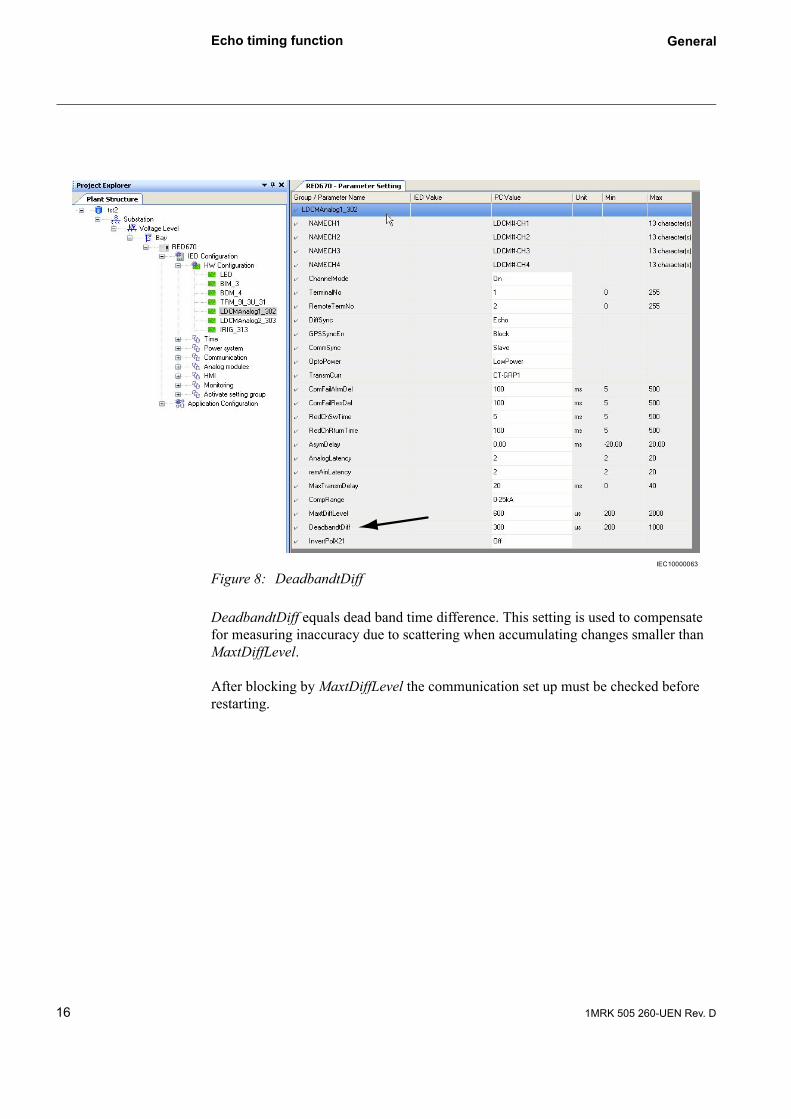
Figure 8: DeadbandtDiff
DeadbandtDiff equals dead band time difference. This setting is used to compensate for measuring inaccuracy due to scattering when accumulating changes smaller than MaxtDiffLevel.
After blocking by MaxtDiffLevel the communication set up must be checked before restarting.
IEC10000063
16 1MRK 505 260-UEN Rev. D

RED670 with built-in external GPS clock or with GeneralRED670 with built-in external GPS clock or with IRIGB-00X input for unspecified route switching
3 RED670 with built-in external GPS clock or with IRIGB-00X input for unspecified route switching
For telecommunication networks with unspecified route switching RED670 with built in GPS clock must be used. Thus, the differential protection can operate correctly, independent of asymmetric delays in the communication channels. The maximum allowed time delay in the telecommunication system is settable, 0-2 x 20 ms = 40 ms, as the sum of the delay in both directions. It is also possible to make an asymmetric split, for example 10 ms in one direction and 30 ms in the other direction as the delay can be accurately measured when GPS timing is available. For longer delays, the dif-ferential function is blocked.
Figure 9: Three end application with GPS
3.1 Start up of the GPS system (cold start)With the antenna placed for good visibility, the GPS system takes up to 15 minutes to find the satellites (minimum 4) and start synchronizing the internal clocks in the RED670 with the global time from the GPS system.
171MRK 505 260-UEN Rev. D

RED670 with built-in external GPS clock or with IRIGB-00X input for unspecified route switching
General
Figure 10:Setting GPS clock
At the beginning of the synchronization procedure, the internal clocks in the RED670s are adjusted to have the correct global time in seconds, only integers are set. The remaining fractional part to reach global time, milliseconds (ms) and microseconds (µs), are used to slowly synchronize the RED670 internal clocks to global time.
The synchronization of the internal clock to the global time is done with a rate of 1 ms/s to reach the global time. When the RED670 internal clock is within 16µs from the global time, the differential function is enabled. Thereafter a soft calibration is per-formed, in which the RED670 internal clock is synchronized to maintain the global time + 1µs for a period of time, especially important during interruptions in the GPS system. When the internal clock and the global time deviates more than 16 µs, the GPS timing is deactivated. If only GPS is used the differential protection is blocked or the back-up echo timing enabled.
3.2 Time synchronizationThe time system is based on a “software clock”, which can be adjusted from external time sources and a hardware clock. The protection and control modules will be timed from a “hardware” clock, which runs independently from the “software” clock. See figure below.
*
*IEC10000203
18 1MRK 505 260-UEN Rev. D

RED670 with built-in external GPS clock or with GeneralRED670 with built-in external GPS clock or with IRIGB-00X input for unspecified route switching
Figure 11: Design of time system (clock synchronization)
All time tagging is performed by the “software” clock. When for example a status sig-nal is changed in the protection system with the function based on ”free running hard-ware” clock, the event is time tagged by the software clock when it reaches the event recorder. Thus the “hardware” clock can run independently.
The echo mode for the differential protection is based on the “hardware” clock. Thus, there is normally no need to synchronize the “hardware” clock and the “software” clock. If a GPS clock is used for other products in the 670-series than current differen-tial RED670, i.e. the “hardware” and “software” clocks are not synchronized.
The synchronization of the “hardware” clock and the “software” clock is necessary only when GPS or IRIG B 00X with optical fibre, IEEE 1344 is used for the differen-tialprotection. The two clock systems are synchronized by a special clock synchroniza-tion unit with two modes, fast and slow. The setting fast or slow is available on the HMI or in PCM600.
Fast shall be used when GPS timing without echo back-up is selected to block the dif-ferential when the GPS is lost.
LON SPA
GPS SNTP
IRIG-B PPS
Off
SW-time
Time- Regulator
(Fast or slow)
HW-time
Protection and control functions
Time tagging and general synchronization
Time- Regulator
(Setting,
see TRM)
Commu -nication
Events
A/D converter
Synchronization for differential protection
(ECHO-mode or GPS)
Diff. commu -nication
*IEC 61850-9-2
Connected when GPS-time is used for differential protection
Min. pulse
DNP
en08000287.vsd
External Synchronization
sources
Trans-ducers*
191MRK 505 260-UEN Rev. D

RED670 with built-in external GPS clock or with IRIGB-00X input for unspecified route switching
General
Slow shall be used when GPS timing with echo back-up or echo timing is selected.
Fast clock synchronization mode
At start-up and after interruptions in the GPS or IRIG B time signal, the clock devia-tion between the GPS time and the internal differential time system can be substantial. A new start-up is also required after for example maintenance of the auxiliary voltage system. The fast mode makes the synchronization time as short as possible during start-up or at interruptions/disturbances in the GPS timing.
When the time difference is >16 µs, the differential function is blocked and the time regulator for the hardware clock is automatically using a fast mode to synchronize the clock systems. The time adjustment is made with an exponential function, i.e. big time adjustment steps in the beginning, then smaller steps until a time deviation between the GPS time and the differential time system of <16 µs has been reached. Then the differ-ential function is enabled and the synchronization remains in fast mode or switches to slow mode, depending on the setting. The ”Fast” setting has 1 ms/s second adjustment rate.
Slow clock sychronization mode
During normal service, a setting with slow synchronization mode is normally used, which prevents the hardware clock to make too big time steps, >16 µs, emanating from the differential protection requirement of correct timing.
At start up a special feature, an automtic fast clock time regulator is used to reduce the synchronization time. After the clock is synchronized to <16 µs the slow clock mode is activated. The “Slow” setting has + 50 µs/s second adjustment rate.
If the echo timing has been enabled as back-up for the GPS system, the RED670 inter-nal clock can not deviate more than +/- 50 µs/s, which is the maximum adjustment rate of the internal clock, depending on the echo timing adjustment capability in a 64 kbit communication system.
This limitation is not valid for echo timing without GPS.
3.3 Setting of GPS via IRIGB00x for RED670 with PCM6001 Select the Fine SyncSource.
20 1MRK 505 260-UEN Rev. D

RED670 with built-in external GPS clock or with GeneralRED670 with built-in external GPS clock or with IRIGB-00X input for unspecified route switching
Figure 12:Select FineSyncSource
2 Set sync type to Opto (default).
3 Set the encoding to 1344.
Figure 13:Set encoding
4 For the real time clock for example for tagging of events select the Time Sync Time zone under Synchronization.
3.4 Accuracy of the GPS systemThe accuracy of the soft calibration of the RED670 internal clocks is dependent of the time the GPS system has been in service. Thus, if the GPS system is lost directly after the differential protection has been enabled, the drift of the clock can be up to 16 µs/second. However, by using software calibration this drift will be reduced to 1µs/sec-ond during a time span of < 1 hour. This reduced drift is also reducing the restart time after a short GPS interruption. If the time difference after the interruption is less than the set MaxtDiffLevel, the differential system can be enabled directly.
211MRK 505 260-UEN Rev. D

RED670 with built-in external GPS clock or with IRIGB-00X input for unspecified route switching
General
3.5 Enabling of the echo timing according to application (I)The echo timing is enabled when the GPS is lost. The enabling of the echo timing will have a delay, depending on how long the GPS has been working after start.
Starting inaccuracy of the internal clock is 16 µs and will go down to ±1µs after some minutes.
3.6 Blocking of the echo-timing after GPS interruptionAs the telecommunication system has unspecified route switching, the echo-timing can only be used with unchanged time delay in both directions (within set limits, see Section 1.2 page 7). As soon as the time delay is outside the set limits the differential function is blocked. Some additional features are included to increase the performance of the echo timing blocking, see below.
a) If redundant or alternative routes are available, these routes are also supervised for change in time delay. If there is no time delay difference in the redundant or alternative route, the echo-timing will continue with the reserve channel.
b) In telecommunication systems with unspecified route switching, time differences below the set limits are accumulated to handle multiple route switching, which together can reach the set time difference limit according to Section 1.2 page 7.
3.7 Selectivity planningA missed protection message due to for example bit errors, prolongs the tripping time. Maximum interruption time and bit error rate should be part of the selectivity plan-ning.
22 1MRK 505 260-UEN Rev. D

Digital signal communication for line differential protection RED670
Introduction
4 Digital signal communication for line differential protection RED670
The line differential protection RED670 uses digital 64 kbit/s communication channels to exchange sampled current values between the ends every 5 ms. Each telegram con-tain current sample values, time information, trip-, block- and alarm signals and eight separate binary signals which can be used for any purpose, for example transfer trip from external protection equipment. Each 670 series equipment can have a maximum of four communication channels.
On a two ended line there is a need of one 64 kbit/s communication channel provided that there is only one CT in each line end as shown in Figure 14.
Figure 14:Two-terminal line
In case of a 1/2 breaker arrangements or ring buses, one line end can have two CTs as shown in Figure 15.
Figure 15:Two-terminal line with a 1/2 breaker
In this case, current values from two CTs in the double breakers, ring main or breaker-and-a-half systems end with dual breaker arrangement need to be sent to the remote end. As a 64 kbit/s channel only has capacity for one three-phase current (duplex), this implies that two communication channels will be needed, and this is also the normal solution.
Alternatively, it is possible to sum and check the two local currents before sending them and in that way reduce the number of communication channels needed. The eval-uation is then made in software in the 670 series, but doing it in this way, there will be reduced information about bias currents in the two CTs.
231MRK 505 260-UEN Rev. D1MRK 505 260-UEN Rev. D

Digital signal communication for line differential protection RED670
Introduction
In RED670, the bias current is considered the greatest phase current in any line end and it is common for all three phases. When sending full information from both local CTs to the remote end, as shown in Figure 15, this principle works, but when the two local currents are added together before sending the single resulting current on the sin-gle communication channel, information about the real phase currents from the two local CTs will not be available in the remote line end.
Whether it will be possible to use one communication channel instead of two (as shown in Figure 15) must be decided from case to case. It must be realized that correct information about bias currents will always be available locally, whilst only limited information will be available at the end, that receives the limited information over only one channel.
For the configuration of redundant channels see Section 4.5 page 27. For further infor-mation see Chapter Remote communication, in “Application manual”.
4.1 Configuration of analog and binary signals - Line Data Communi-cation Module (LDCM)The communication between the 670 series protection and control products is pro-vided by a Line Data Communication Module. The abbreviation LDCM is used in the entire text.
The selection of an analog or binary LDCM is made in PCM600.
Figure 16:Selection of LDCM for analog or binary transferIEC10000229
24 1MRK 505 260-UEN Rev. D

Digital signal communication for line differential protection RED670
Introduction
4.2 Configuration of analog signalsThe currents from the local end enter RED670 via the Analog Input Modules as analog values. These currents need to be converted to digital values and then forwarded to the line differential function in the local RED670, as well as being transmitted to a remote RED670 via a Line Data Communication Module with either fiberoptic C37.94 or gal-vanic X.21 at 64 kbit. The currents from a remote RED670 are received as digital val-ues in the local RED670 via an LDCM and is thereafter forwarded to the line differential function in the local RED670.
The engineering tool PCM600, protection and control manager is used for the configu-ration and setting of the 670 series. The abbreviation PCM will be used in the follow-ing text. The Signal Matrix tool, SMT is used to configure and connect input and output signals. The abbreviation SMT will be used in the following text.The configu-ration of this data flow is made in the SMT tool in PCM600 which is principally shown in Figure 17, next page.
Figure 17:Typical configuration of the analog signals for a three ended line
Figure 17 shows how one IED in a three ended line differential protection can be con-figured. Especially notice that there are two LDCMs, each one supporting a duplex connection with a remote line end. Thus, the same local current is configured to both LDCMs, whilst the received currents from the LDCMs are configured separately to the line differential function.
IEC10000066
251MRK 505 260-UEN Rev. D

Digital signal communication for line differential protection RED670
Introduction
4.3 Copfiguration of analog inputsThe analog inputs are configured in PCM600, see example below.
Figure 18:Configuration of analogue inputs
4.4 Configuration of an analog LDCM for binary output signals (8 in, 8 out)There are a number of signals available from the LDCM that can be connected to the virtual binary inputs (SMBI) in the 670 series and used internally in the configuration. The signals appear only in the SMT tool where they can be mapped to the desired vir-tual input.
See Chapter 5 Analog and binary signal transfer for the 670 series page 28, Binary sig-nal transfer to remote end in “Technical reference manual” for more detailed explana-tion of the signals. The signal name is found in the Object Properties window by clicking on the input signal number in the SMT tool. Connect the signals to the virtual inputs as desired. See Figure 19.
IEC10000231
26 1MRK 505 260-UEN Rev. D

Digital signal communication for line differential protection RED670
Introduction
Figure 19:Example of LDCM signals as seen in the Signal matrix tool
Figure 20:Typical LDCM application
4.5 Configuration of redundant channelsLDCM installation sequence: slot 312, slot 313, slot 322, slot 323, slot 302 and slot 303.
2-4 LDCM can be included depending of availability of IRIG-B respective RS485 modules. IRIG-B will be seated in slot 302 and RS485 will be seated in slot 312.
IEC10000230
LDCM
LDCM
LDCMLDCM
LDCMLDCM
LDCM
LDCM
LDCMLDCM
LDCMLDCM
Telecom. Network
Multiplexer Multiplexer
LDCM LDCM
en07000228.wmf
271MRK 505 260-UEN Rev. D

Digital signal communication for line differential protection RED670
Introduction
Slots 303, 313 and 323 can be set as redundant line differential communication channel in PCM600.
Figure 21:Typical application with redundant channels
Warning:The redundant channels must be configured in the same way in both ends of the differ-ential communication link, otherwise an unwanted trip may occur when the main channel fails and the redundant channel is enabled.
a) Thus it is not allowed to have a LDCM for the redundant channel only in one end.
b) The SMT configuration for the redundant channel must be left empty. The redun-dant channel will take over the signal matrix configuration from the main channel at enabling. If the redundant channel has, for example, been allocated current inputs with the SMT tool in one end or in both ends, an unwanted trip will occur.
Primary channel
Secondary redundant (reserve) channel
LDC
MLDC
M
LDC
MLDC
M
LDC
ML
DCML
DCM
LDC
M
en07000229.wmf
Telecom.Network
LDC
MLDC
M
LDC
MLDC
M
LDC
ML
DCML
DCM
LDC
M
For two or three line ends
Telecom.Network
28 1MRK 505 260-UEN Rev. D

Digital signal communication for line differential protection RED670
Introduction
Figure 22:Designation for 1/1x9” casing with 2 TRM slots
Note:Main and redundant channel is placed on the same base card in slot 303-302, 313-312 and 323-322. For more details, see Figure 22.
Can be set as main and redundant channelor two independent channels
en1mrk002801-AB_6_revA_redundant channel.eps
**
* Note that IRIG-B, (slot 30:2) and RS485,(slot 31:2) modules have dedicated positions
291MRK 505 260-UEN Rev. D

Digital signal communication for line differential protection RED670
Introduction
Figure 23:Signal Matrix for one LDCM
Figure 24:Signal Matrix for two channels, one redundant
The position for the main and redundant channels are predefined in the basic configu-ration, in other words they can not be shifted. The signal matrix for the redundant channel must be empty. It is automatically updated when the main channel is lost. See Figure 24, above.
30 1MRK 505 260-UEN Rev. D

Digital signal communication for line differential protection RED670
Introduction
Figure 25:Setting example of RED670 with redundant channel (two duplex channels)IEC10000070
311MRK 505 260-UEN Rev. D

Binary signal transfer for the 670 series Introduction
5 Binary signal transfer for the 670 series
REL 670, REC 670, REB 670 and REG 670 can utilize the same 64 kbit communica-tion facilities for binary signal transfer of up to 192 external or internal logical signals, for example Carrier Send, Carrier Receive, block signals, control signals etc.
The line differential protection RED670 can transfer 8 binary signals.
Figure 26:Two-terminal line
The start and stop flags are the 0111 1110 sequence (7E hexadecimal), defined in the HDLC standard. The CRC is designed according to the standard CRC16 definition. The optional address field in the HDLC frame is not used. Instead a separate address-ing is included in the data field. The address field is used for checking that the received message originates from the correct equipment. There is always a risk that multiplex-ers occasionally mix the messages up. Each point in the system is given a number. The 670 series is then programmed to accept messages from a specific IED number. If the CRCfunction detects a faulty message, the message is thrown away and not used in the evaluation. When the communication is used exclusively for binary signals, the full data capacity of the communication channel is used for the binary signal purpose which gives the capacity of 192 signals
Figure 27:Setting example of RED670 with one communication channel for binary transfer
32 1MRK 505 260-UEN Rev. D

Binary signal transfer for the 670 series Introduction
5.1 Function blockNote!
There is no function block for the LDCM they are instead represented as hardware channels in ACT and in SMT. Where they can be found in the top margin. The signals appear only when a LDCM is included in the Hardware Configuration Tool. It is pos-sible to use either ACT or SMT to configure the LDCM signals.
5.2 ACT Configuration of binary inputs and outputs for binary signal transferIn ACT LDCM Hardware Channels can be connected by putting the pointer (arrow) over the connection point. The arrow will than changes to a pointing hand, right click and select Connect/Hardware Channel.
Note
If a LDCM is not used, it shall be disabled with the hardware configuration too. Other-wise parallel LDCMs can be blocked.
Figure 28:ACT configuration of binary inputs and outputs
IEC10000241.vsd
331MRK 505 260-UEN Rev. D

Binary signal transfer for the 670 series Introduction
In the dialog Hardware Channel Allocation it is possible to select: Hardware Module, Hardware Channel and User Define Name where the channel name is given.
Figure 29:Dialog Hardware Channel Allocation
Figure 30:The result of selected Hardware Channels might look like
When User Define Name for the Hardware Channel is given it will also be visible in SMT.
IEC10000242.vsd
IEC10000243.vsd
34 1MRK 505 260-UEN Rev. D

Binary signal transfer for the 670 series Introduction
Figure 31:User define name is visible in SMT
5.3 Configuration of binary output (SMBO) and input (SMBI) signalsin Signal Matrix Tool (SMT).The configuration of binary signals for binary signal transfer in SMT is basically done by selecting accurate TAB.
Figure 32:TAB selecting in SMT
IEC10000244.vsd
IEC10000247.vsd
351MRK 505 260-UEN Rev. D
Binary signal transfer for the 670 series Introduction
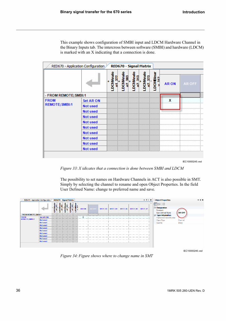
This example shows configuration of SMBI input and LDCM Hardware Channel in the Binary Inputs tab. The intercross between software (SMBI) and hardware (LDCM) is marked with an X indicating that a connection is done.
Figure 33:X idicates that a connection is done between SMBI and LDCM
The possibility to set names on Hardware Channels in ACT is also possible in SMT. Simply by selecting the channel to rename and open Object Properties. In the field User Defined Name: change to preferred name and save.
Figure 34:Figure shows where to change name in SMT
IEC10000245.vsd
IEC10000246.vsd
36 1MRK 505 260-UEN Rev. D

Binary signal transfer for the 670 series Introduction
Figure 35:Configuration of received signals
Figure 36:Configuration of communication alarms
IEC10000237
371MRK 505 260-UEN Rev. D

Binary signal transfer for the 670 series Introduction
Figure 37:Disconnection of analogue signals for binary signal transfer set-up
5.4 Analog and binary input and output signalsIn the PCM600 configuration and setting tool, the communication module (LDCM) has an affix, either CRM or CRB, which defines actual type of signal transfer.
CRM 1-6; Remote Communication Multi is used to send both analog and binary sig-nals (RED670).
CRB 1-6; Remote Communication Binary is used to send binary signals (remaining IED 670).
CRM and CRB number 1-6 has predefined slots in the IED 670 hardware. Only four slots can be used simultaneously.
IEC10000239
Table 1: Predefined slots for analog and binary signalsAnalog and binary signals Binary signals Communication slot
CRM- 1 CRB- 1 302
CRM- 2 CRB- 2 303
CRM- 3 CRB- 3 312
CRM- 4 CRB- 4 313
CRM- 5 CRB- 5 322
CRM- 6 CRB- 6 323
38 1MRK 505 260-UEN Rev. D

Binary signal transfer for the 670 series Introduction
5.5 Setting guidelinesChannel mode: This parameter can be set ON or OFF. If OFF is set with locally meas-ured currents (analog inputs) trip and transfer trip will be issued. Besides this, it can be set OutOfService which signifies that the local LDCM is out of service. Thus, with this setting, the communication channel is active and a message is sent to the remote IED that the local IED is out of service, but there is no COMFAIL and the analog and binary values are sent as zero.
Table 2: Output signals for the LDCMRecBinStat (CRM1-) function block in ana-log mode (see also section 11, fault tracing)
Signal Description
COMFAIL Detected error in the differential communication
YBIT Detected error in remote end with incoming message
NOCARR No carrier is detected in the incoming message
NOMESS No start and stop flags identified for the incoming message
ADDRERR Incoming message from a wrong terminal
LNGTHERR Wrong length of the incoming message
CRCERROR Identified error by CRC check in incoming message
TRDELERR Transmission time is longer than permitted
SYNCERR Indicates when synchronisation is not correct
REMCOMF Remote terminal indicates problem with received message
REMGPSER Remote terminal indicates problem with GPS synchronization
SUBSTITU Link error, values are substituted
LOWLEVEL Low signal level on the receive link
Table 3: Binary output signals for the LDCMRecBinStat (CRB1-) function block in binary mode (see also section 11, fault tracing)
Signal Description
COMFAIL Detected error in the differential communication
YBIT Detected error in remote end with incoming message
NOCARR No carrier is detected in the incoming message
NOMESS No start and stop flags identified for the incoming message
ADDRERR Incoming message from a wrong terminal
LNGTHERR Wrong length of the incoming message
CRCERROR Identified error by CRC check in incoming message
REMCOMF Remote terminal indicates problem with received message
LOWLEVEL Low signal level on the receive link
Note:Only applicable for no-load conditions; for example during maintenance of a HV-breaker.
391MRK 505 260-UEN Rev. D

Binary signal transfer for the 670 series Introduction
TerminalNo: This setting assigns a number to the local REX 670. Up to 256 REX 670 can be assigned unique numbers. For aline differential protection, maximum 6 IEDs can be included. The possibility to use the large number of IED designations is reserved for the case where a high security against incorrect addressing in multiplexed systems is desired.
RemoteTermNo: this setting assigns a terminal number to the remote IED.
DiffSync: Here the method of time synchronization, Echo or GPS, for the line differential function is selected.
GPSSyncErr: If GPS synchronization is lost, the synchronization of the line differen-tial function will continue during 16 s. based on the stability in the local 670 units clocks. Thereafter the setting Block will block the line differential function or the set-ting Echo will make it continue by using the Echo synchronization method. It shall be noticed that using Echo in this situation is only safe as long as there is no risk of vary-ing transmission asymmetry.
CommSync: This setting decides the Master/Slave relation in the communication system and shall not be mistaken for the synchronization of line differential current samples. When direct fibre is used, one LDCM is set as Master and the other one as Slave. When a modem and multiplexer is used, the REX 670 is always set as Slave, as the telecommunication system will provide the clock master.
OptoPower: The setting LowPower is used according to table 7, page 37.
TransmCurr: This setting decides which of 2 possible local currents that shall be trans-mitted, or if and how the sum of 2 local currents shall be transmitted, or finally if the channel shall be used as a redundant channel.
In a 1 ½ breaker arrangement, there will be 2 local currents, and the grounding on the CTs can be different for these. CT-SUM will transmit the sum of the 2 CT groups. CT-DIFF1 will trans-mit CT group 1 minus CT group 2 and CT-Diff2 will transmit CT group 2 minus CT group 1.
CT-GRP1 or CT-GRP2 will transmit the respective CT group, and the setting RedundantChannel makes it possible to use the channel as a backup channel.
ComFailAlrmDel: Time delay of communication failure alarm. In communication sys-tems, route switching can sometimes cause interruptions with a duration up to 50 ms. Thus, a too short time delay setting might cause nuisance alarms in these situations.
ComFailResDel: Time delay of communication failure alarm reset.
RedChSwTime: Time delay before switchover to redundant channel in case of primary channel failure.
RedChRturnTime: Time delay before switchback to the primary channel after channel failure.
40 1MRK 505 260-UEN Rev. D

Binary signal transfer for the 670 series Introduction
AsymDelay: the asymmetry is defined as transmission delay minus receive delay. If a fixed asymmetry is known, the Echo synchronization method can be used if the param-eter AsymDelay is properly set. From the definition follows that the asymmetry will always be positive in one end, and negative in the other end.
LocAinLatency: a parameter which specifies the time delay (number of samples) between actual sampling and the time the sample reaches the local commmunication module, LDCM. The parameter shall be set to 2 when transmitting analogue data from the local transformer module (TRM). When a merging unit according to IEC 61850-9-2 is used instead of the TRM this parameter shall be set to 5.
RemAinLatency: this parameter corresponds to the LocAinLatency set in the remote IED.
Figure 38:Setting example of AsymDelay for RED670
MaxTransmDelay: Data for maximum 40 ms transmission delay can be buffered up. Delay time in the range of some ms are common. It shall be noticed that if data arrive in the wrong order, the oldest data will just be disregarded.
CompRange: the set value is current peak value over which truncation will be made. To set this value, knowledge of the fault current levels should be known. The setting is not overly critical as it considers very high current values for which correct operation normally still can be achieved.
en7000235.wmf
RED670
RED670
A B
2 ms delay
2 ms delay 1 ms delay
TxRx
RxTx
C*
*The 3 ms delay in route A-C-B includes the delay in the multiplexer in end C.
RED670RED670
RED670RED670
AsymDelay for RED 670 in end A is set 3 ms - 2 ms = 1 msAsymDelay for RED 670 in end B is set 2 ms - 3 ms = -1 ms
AA BB
2 ms delay
2 ms delay 1 ms delay
TxRx
RxTx
C*C*
*The 3 ms delay in route A-C-B includes the delay in the multiplexer in end C.The setting can be found under LDCM configuration/CRM-CRB/AsymDelay
Setting example:
RED670
RED670
A B
2 ms delay
2 ms delay 1 ms delay
TxRx
RxTx
C*
*The 3 ms delay in route A-C-B includes the delay in the multiplexer in end C.
RED670RED670
RED670RED670
AA BB
2 ms delay
2 ms delay 1 ms delay
TxRx
RxTx
C*C*
*The 3 ms delay in route A-C-B includes the delay in the multiplexer in end C.The setting can be found under LDCM configuration/CRM-CRB/AsymDelay
Setting example:
411MRK 505 260-UEN Rev. D

Binary signal transfer for the 670 series Introduction
5.5.1 Setting parameters
Table 4: Basic general settings for the LDCMRecBinStat (CRM1-) functionParameter Range Step Default Unit Description
ChannelMode OffONOutOfService To be used in multitermi-nal lines for exam-ple maintenance in one end to avoid communication fail-ure and different protect blocking in remaining RED670.
- ON - Channel mode of LDCM, 0=OFF, 1=ON, 2=OutOf-Service
TerminalNo 0 - 255 1 0 - Terminal number used for line differential communi-cation
RemoteTermNo 0 - 255 1 0 - Terminal number on remote terminal
DiffSync ECHOGPS
- ECHO - Diff Synchronization mode of LDCM, 0=ECHO, 1=GPS
GPSSyncErr BlockEcho
- Block - Operation mode when GPS synchroniation sig-nal is lost
CommSync SlaveMaster
- Slave - Com Synchronization mode of LDCM, 0=Slave, 1=Master
OptoPower LowPowerHighPower
- LowPower - Transmission power for LDCM, 0=Low, 1=High
TransmCurr CT-GRP1CT-GRP2CT-SUMCT-DIFF1CT-DIFF2
- CT-GRP1 - Summation mode for transmitted current values
ComFailAlrmDel 5 - 500 5 10 ms Time delay before com-munication error signal is activated
ComFailResDel 5 - 500 5 10 ms Reset delay before com-munication error signal is reset
RedChSwTime 5 - 500 5 5 ms Time delay before switch-ing in redundant channel
RedChRturnTime 5 - 500 5 100 ms Time delay before switch-ing back from redundant channel
AsymDelay -20.00 - 20.00 0.01 0.00 ms Asymmetric delay when communication use echo synch.
MaxTransmDelay 0 - 40 1 20 ms Max allowed transmis-sion delay
42 1MRK 505 260-UEN Rev. D

Binary signal transfer for the 670 series Introduction
CompRange 0-10kA0-25kA0-50kA0-150kA
- 0-25kA - Compression range
MaxtDiffLevel 200 - 2000 1 600 µs Maximum time diff for ECHO back-up
DeadbandtDiff 200 - 1000 1 300 µs Deadband for t Diff
InvertPolX.21 OffON
- Off - Invert polarization for X.21 communication
Table 5: Basic general settings for the LDCMRecBinStat (CRM2-) function
Parameter Range Step Default Unit Description
ChannelMode OffONOutOfService
- ON - Channel mode of LDCM, 0=OFF, 1=ON, 2=OutOf-Service
TerminalNo 0 - 255 1 0 - Terminal number used for line differential communi-cation
RemoteTermNo 0 - 255 1 0 - Terminal number on remote terminal
DiffSync ECHOGPS
- ECHO - Diff Synchronization mode of LDCM, 0=ECHO, 1=GPS
GPSSyncErr BlockEcho
- Block - Operation mode when GPS synchroniation sig-nal is lost
CommSync SlaveMaster
- Slave - Com Synchronization mode of LDCM, 0=Slave, 1=Master
OptoPower LowPowerHighPower
- LowPower - Transmission power for LDCM, 0=Low, 1=High
TransmCurr CT-GRP1CT-GRP2CT-SUMCT-DIFF1CT-DIFF2RedundantChannel
- CT-GRP1 - Summation mode for transmitted current values
ComFailAlrmDel 5 - 500 5 100 ms Time delay before com-munication error signal is activated
ComFailResDel 5 - 500 5 10 ms Reset delay before com-munication error signal is reset
RedChSwTime 5 - 500 5 5 ms Time delay before switch-ing in redundant channel
RedChRturnTime 5 - 500 5 100 ms Time delay before switch-ing back from redundant channel
Table 4: Basic general settings for the LDCMRecBinStat (CRM1-) functionParameter Range Step Default Unit Description
431MRK 505 260-UEN Rev. D

Binary signal transfer for the 670 series Introduction
AsymDelay(Refers to fixed routes with known asymmetric delay)
-20.00 - 20.00 0.01 0.00 ms Asymmetric delay when communication use echo synch.
LocAinLatency 2-20 1 2 sam-ples
Time delay between actual sampling and the time the sample reaches the local communication module (LDCM)
RemAinLatency 2-20 1 2 sam-ples
Time delay between actual sampling and the time the sample reaches the local communication module (LDCM)
MaxTransmDelay 0 - 40 1 20 ms Max allowed transmis-sion delay
CompRange 0-10kA0-25kA0-50kA0-150kA
- 0-25kA - Compression range
MaxtDiffLevel 200 - 2000 1 600 µs Maximum time diff for ECHO back-up
DeadbandtDiff 200 - 1000 1 300 µs Deadband for t Diff
InvertPolX.21 OffON
- Off - Invert polarization for X.21 communication
Table 6: Basic general settings for the LDCMRecBinStat (CRB1-) function
Parameter Range Step Default Unit Description
ChannelMode OffOnOutOfService
- On - Channel mode of LDCM, 0=OFF, 1=ON, 2=OutOf-Service
TerminalNo 0 - 255 1 0 - Terminal number used for line differential communi-cation
RemoteTermNo 0 - 255 1 0 - Terminal number on remote terminal
CommSync SlaveMaster
- Slave - Com Synchronization mode of LDCM, 0=Slave, 1=Master
OptoPower LowPowerHighPower
- LowPower - Transmission power for LDCM, 0=Low, 1=High
ComFailAlrmDel 5 - 500 5 10/100 depending on version
ms Time delay before com-munication error signal is activated
ComFailResDel 5 - 500 5 10 ms Reset delay before com-munication error signal is reset
Table 5: Basic general settings for the LDCMRecBinStat (CRM2-) function
Parameter Range Step Default Unit Description
44 1MRK 505 260-UEN Rev. D

Binary signal transfer for the 670 series Introduction
InvertPolX.21 OffOn
- Off - Invert polarization for X.21 communication
Table 6: Basic general settings for the LDCMRecBinStat (CRB1-) function
Parameter Range Step Default Unit Description
Note:ComfailAlrmDel; COMFAIL Alarm Delay:ComFailAlrmDel should be set ≥ 100 ms, in normal service. Route switching in tele-communication networks normally takes < 50 ms.ComFailResDelay should be set at 10 ms.
(For fault tracing it can be advantageous to set the ComFailAlrmDel at 5 - 10 ms.)
451MRK 505 260-UEN Rev. D

Communication channels Introduction
6 Communication channels
Each 670 series device can be configured with up to four remote communication inter-faces. The communication configuration for each channel is individually set.
Application examples:
Figure 39:Two ended line with 1 1/2 breaker
Figure 40:Two ended line with 1 1/2 breaker, redundant channels
46 1MRK 505 260-UEN Rev. D

Communication channels Introduction
Figure 41:Multiterminal line for 5 line-ends, master-master
Figure 42:Multiterminal line for 5 line-ends, master-slave
Id> Id> Id>
Id> Id>
en07000148.vsd
471MRK 505 260-UEN Rev. D

Communication alternatives Introduction
7 Communication alternatives
Figure 43:Communication alternatives for 670 series
48 1MRK 505 260-UEN Rev. D
Communication alternatives Introduction
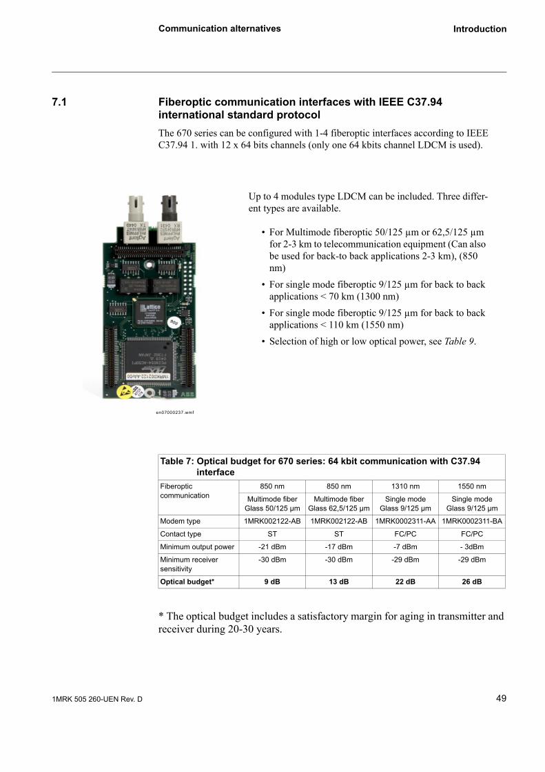
7.1 Fiberoptic communication interfaces with IEEE C37.94 international standard protocolThe 670 series can be configured with 1-4 fiberoptic interfaces according to IEEE C37.94 1. with 12 x 64 bits channels (only one 64 kbits channel LDCM is used).
* The optical budget includes a satisfactory margin for aging in transmitter and receiver during 20-30 years.
Up to 4 modules type LDCM can be included. Three differ-ent types are available.
• For Multimode fiberoptic 50/125 µm or 62,5/125 µm for 2-3 km to telecommunication equipment (Can also be used for back-to back applications 2-3 km), (850 nm)
• For single mode fiberoptic 9/125 µm for back to back applications < 70 km (1300 nm)
• For single mode fiberoptic 9/125 µm for back to back applications < 110 km (1550 nm)
• Selection of high or low optical power, see Table 9.
en07000237.wmf
Table 7: Optical budget for 670 series: 64 kbit communication with C37.94interface
Fiberoptic communication
850 nm 850 nm 1310 nm 1550 nm
Multimode fiberGlass 50/125 µm
Multimode fiberGlass 62,5/125 µm
Single modeGlass 9/125 µm
Single modeGlass 9/125 µm
Modem type 1MRK002122-AB 1MRK002122-AB 1MRK0002311-AA 1MRK0002311-BA
Contact type ST ST FC/PC FC/PC
Minimum output power -21 dBm -17 dBm -7 dBm - 3dBm
Minimum receiver sensitivity
-30 dBm -30 dBm -29 dBm -29 dBm
Optical budget* 9 dB 13 dB 22 dB 26 dB
491MRK 505 260-UEN Rev. D

Communication alternatives Introduction
7.2 Galvanic interface type X.21Introduction
The galvanic X.21 line data communication module is used for connection to telecom-munication equipment, for example leased telephone lines. The module supports 64 kbits/s data communication between IEDs.
Table 8: Example of input data for calculation of optical power budget: Maximum distance
Fiberoptic communication
850 nm 850 nm 1310 nm 1550 nm
Multimode fiberGlass 50/125 µm
Multimode fiberGlass 62,5/125 µm
Single modeGlass 9/125 µm
Single modeGlass 9/125 µm
Modem type 1MRK0002211-AB 1MRK0002122-AB 1MRK002311-AA 1MRK002311-BA
Typical attenuation in fiberoptic cables
3 db/km 3 db/km 0,32 dB/km 0,21 db/km
Attenuation 1,0 dB 1,0 dB 0,3 dB 0,3 dB
Factory splice attenuation
0,25 dB/splice0,1 splices /km
0,25 dB/splice0,3 splices /km
0,08 dB/splice0,1 splices /km
0,08 dB/splice0,3 splices /km
Repair splices attenuation
0,5 dB/splice0,1 splices /km
0,5 dB/splice0,1 splices /km
0,1 dB/splice0,05 splices /km
0,1 dB/splice0,05 splices /km
Fiber margin for aging 0,1 db/km 0,1 db/km 0,01 db/km 0,01 db/km
Table 9: Example calculation of optical power budget: Maximum distanceFiberoptic communication
850 nm 850 nm 1310 nm 1550 nm
Multimode fiberGlass 50/125 µm
Multimode fiberGlass 62,5/125 µm
Single modeGlass 9/125 µm
Single modeGlass 9/125 µm
Modem type 1MRK002122-AB 1MRK0002211-AB 1MRK0002311-AA 1MRK0002311-BA
Maximum distance depending of attenua-tion in actual fibre
2 km 3 km 60 km 110 km
Attenuation in fiberoptic cables
6 dB 9 dB 19,2 dB 23,1 dB
Attenuation 2 Contacts 2 dB 2 dB 0,6 dB 0,6 dB
Factory splice attenua-tion
0,1 dB 0,15 dB 0,48 dB 0,48 dB
Repair splices 0,3 dB 0,3 dB 0,7 dB 0,7 dB
Margin for fiber aging 0,2 db 0,3 dB 0,7 dB 0,7 dB
Attenuation 8,6 dB 11,9 dB 21,68 dB 25,58 dB
Optical budget 9 dB 13 dB 22 dB 26 dB
Extra margin 0,4 dB 1,1 dB 0,036 dB 0,42 dB
If extra margin > values in table 9 set low power
6 dB 8 dB 15 dB 15 dB
50 1MRK 505 260-UEN Rev. D

Communication alternatives Introduction
Example of applications:
• Line differential protection
• Binary signal transfer
7.2.1 DesignThe galvanic X.21 line data communication module uses a ABB specific PC*MIP Type II format.
Figure 44:Overview of the X.21 LDCM module
Figure 45:The X.21 LDCM module external connectors
en07000238.wmf
1 Ground selection connector for IO, screw terminals, 2-pole
2 Ground pin
3 Soft ground pin, see Figure 46 below
4 X.21 Micro D-sub 15 pole male connector according to the V11 (X:27) balanced version
1
23
4
en07000239.wmf
1 8
9 15
511MRK 505 260-UEN Rev. D

Communication alternatives Introduction
Figure 46:Schematic view of soft ground
Grounding
At special problems with ground loops the soft ground connection for the IO-ground can be tested.
Three different kinds of grounding principles can be set (used for fault tracing):
1 Direct ground - The normal grounding is direct ground, connect terminal 2 direct to chassi.
2 No ground- Leave the connector without any connection
3 Soft ground - connect soft ground pin (3), see Figure 46 above
52 1MRK 505 260-UEN Rev. D

Communication alternatives Introduction
X.21 Connector
7.2.2 FunctionalityThe data format is HDLC. The speed for the transmission of the messages used is 64 kbit/s.
A maximum of 100 meter of cable is allowed to ensure the quality of the data (deviation from X.21 standard cable length).
Synchronization
The X.21 LDCM works like a DTE (Data Terminal Equipment) and is normally expecting synchronization from the DCE (Data Circuit equipment). The transmission is normally synchronized to the Signal Element Timing signal when a device is a DTE. When the signal is high it will read the data at the receiver and when the signal is low it will write data to the transmitter. This behaviour can be inverted in the control register.
Normally an external multiplexer is used and it should act like the master.
When two X.21 LDCM is directly communicating with each other one must be set as a master generating the synchronization for the other (the slave). The DTE signal Element Timing is created from the internal 64 kHz clock.
The Byte Timing signal is not used in ABB devices.
Table Pin-out for the X.21 communication connector
Pin number Signal
1 Shield (ground)
2 TXD A
3 Control A
4 RXD A
6 Signal timing A
8 Ground
9 TXD B
10 Control B
11 RXD B
13 Signal timing B
5, 7, 12, 14, 15 Not used
531MRK 505 260-UEN Rev. D

Communication alternatives Introduction
7.2.3 Technical data
Quantity Range of value
Connector, X.21 Micro D-sub, 15-pole male, 1.27 mm (=.050”) pitch
Connector, ground selection 2 pole screw terminal
Standard CCITT X.21
Communication speed 64 kbit/s
Insulation 1 kV
Maximum cable length 100 m
54 1MRK 505 260-UEN Rev. D
PDH telecommunication system Introduction
8 PDH telecommunication system
PDH telecommunication system set-up with 64 kbit/s C37.94 interface to transceiver type 21-216, or X.21 directly to telecommunication systems.For PDH telecommunication systems with 21-219, see section 10.
8.1 General communication requirementsThere is a short delay in alarm time, normally 100 ms, for the communication fail in the relay, derived from the dependability of the differential protection function. This will require a high quality communication system, see “Appendix 1” on page 69.
If the telecommunication system is disturbed more than 100 ms, an alarm will be cor-rectly issued.
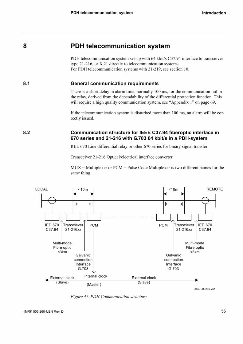
8.2 Communication structure for IEEE C37.94 fiberoptic interface in 670 series and 21-216 with G.703 64 kbit/s in a PDH-systemREL 670 Line differential relay or other 670 series for binary signal transfer
Transceiver 21-216 Optical/electrical interface converter
MUX = Multiplexer or PCM = Pulse Code Multiplexer is two different names for the same thing.
Figure 47:PDH Communication structure
LOCAL REMOTE<10m<10m
IED 670C37.94
Transciever21-216xx
PCM PCM Transciever21-216xx
IED 670C37.94
Multi-modeFibre optic
<3km
Multi-modeFibre optic
<3kmGalvanic
connectionInterface
G.703
GalvanicconnectionInterface
G.703
Internal clock
(Master)
External clock(Slave)
External clock(Slave)
en07000260.vsd
551MRK 505 260-UEN Rev. D

PDH telecommunication system Introduction
8.3 Service settings of 21-216Fiber Optic Port
Figure 48:The fiber optic connector is of ST type.
Confirm the attenuation of the fiber optic cable, including splices and patch cables, does not exceed the system budget. Do not forget to add a safety margin. Minimum safety margin is 3dB.
Make sure that the local fiber optic transmitter, marked Tx, is connected to the remote units fiber optic receiver, marked Rx.Local Rx shall be connected to remote Tx.
.
Figure 49:G.703 64kbit/s Codir Port
en07000247.wmf
en07000248.wmf
56 1MRK 505 260-UEN Rev. D

PDH telecommunication system Introduction
Use a cable with twisted pairs and a high quality shield. Only foil shielding is not enough.Rx+ and Rx- should form one twisted pair - Tx+ and Tx- another twisted pair. A Cat5 S/FTP-cable, /Shielded/Foil Twisted Pair) used for example in Ethernet com-munication is a good cable. The outer shield is a braided mesh around the cable. In addition every twisted pair has a foil-shielding.
If a S7FTP patchcable for Ethernet is used, be aware that a cross-connected cable has only the pairs on pin 1-2 and 3-6 cross-connected, the two remaining pairs are not cross-connected.
Clock configuration switch
From 21-216 revision 2 and later, a rotary switch is added to the front panel, to ease installation and testing.
When two 21-216 are used in a PDH or a PDH/SDH system the two 21-216 shall be set as slaves, i.e. when external clock is used.
Back-to-back testing
For testing back-to-back with the G703 ports directly connected, one of the 21-216 shall be set as Master (internal clock).
RJ45 pin Name Direction
1 Tx+ (TIP-out) From 21-216 to multiplexer
2 Tx- (RING-out) From 21-216 to multiplexer
4 Rx+ (TIP-in) From multiplexer to 21-216
5 Rx- (RING-in From multiplexer to 21-216
Metal house Shield Cable shield must be connected
571MRK 505 260-UEN Rev. D

PDH telecommunication system Introduction
8.3.1 Clock synchronization configurationA rotary switch on the front panel can be used for clock synchronization configu-ration.
The rotary switch has 16 positions, (HEX-switch).
Figure 50:Clock configuration switch
At position 0 the switch’s arrow, visible through the adjusting hole, points straight down. In position 0, external clock is selected (default).
.
When a “not used” channel is selected or if both codir and fiber clock are selected, the ERR-LED on the front panel is lit.
Position Function0 External clock is selected (Slave)1 External clock is selected and inverted (Slave)2 Internal clock is selected (Master)3 Internal clock is selected and inverted (Master)
4-7 Reserved for future use8-15 Reserved for factory testing
en07000249.wmf en07000251.wmf en07000252.wmf
58 1MRK 505 260-UEN Rev. D

PDH telecommunication system Introduction
8.4 Start and usagePower on
Connect the power cord to the 21-216 and then connect to mains.
If the link doesn’t work, try to cross-connect the fiber at one end.
8.4.1 LED-statusThere are 12 LED-indicators at the front panel.
Figur 51: Front panel
PowerA green LED lit when power is connected to the unit.
RARemote Alarm. A red LED indicating that the remote unit has encounter a fault condi-tion and has set A red LED indicating that the remote unit has encounter a fault condi-tion and has set the “Yellow Alarm bit” in the IEEE C37.94 protocol.
LALocal Alarm. A red LED indicating that the 21-206 has encounter a fault in the IEEE C37.94 protocol -LOS Loss Of Signal. The “Yellow Alarm bit” is set in the outgoing IEEE C37.94 protocol
ERRError. A red LED indicating that the 21-216 has detected an internal error.The ERR-LED also indicates that not allowed setting of jumpers is made.
LFLink Fiber. A green LED indicating that the 21-216 receives correct IEEE C37.94 frames, (no LOS).
LTLink Twisted pair/G.703 codir. A green LED indicating that 21-216 receives G.703 codir 64kbit/s protocol.
en07000254.wmf
591MRK 505 260-UEN Rev. D

PDH telecommunication system Introduction
RxFReceive data on Fiber. A green LED indicating that 21-216 receives data in IEEE C37.94 format.
RxTReceive data on twisted pair/G.703 codir. A green LEED indicating that 21-216 receives data in G.703 codir protocol.
ChannelFor yellow LED’s representing the channel chosen by jumpers at installation.The channel is “calculated” by adding the lit LED’s.for example if LED 1 and LED 2 are lit 1+2=3 Channel 3 is chosen.This means that data to/from G.703.codir-port is sent and received on the IEEE C37.94 protocol on the fiber.
Clock synchronization configuration
Clock synchronization configuration can be done “on the fly” with the rotary switch on the front panel. Se chapter “Service settings of 21-216”
8.5 Service settings of 670 series with G.703 co-directional
Figure 52:CRM3 set as slaveIEC10000072
60 1MRK 505 260-UEN Rev. D
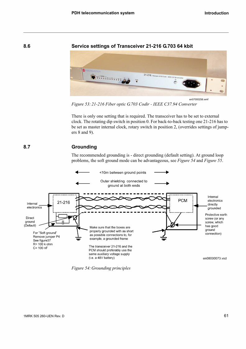
PDH telecommunication system Introduction
8.6 Service settings of Transceiver 21-216 G.703 64 kbit
Figure 53:21-216 Fiber optic G.703 Codir - IEEE C37.94 Converter
There is only one setting that is required. The transceiver has to be set to external clock. The rotating dip switch in position 0. For back-to-back testing one 21-216 has to be set as master internal clock, rotary switch in position 2, (overrides settings of jump-ers 8 and 9).
8.7 GroundingThe recommended grounding is - direct grounding (default setting). At ground loop problems, the soft ground mode can be advantageous, see Figure 54 and Figure 55.
Figure 54:Grounding principles
en07000256.wmf
611MRK 505 260-UEN Rev. D

PDH telecommunication system Introduction
Figure 55:Ground select jumper
The strapping area/jumper P4 selects how internal signalground and chassieground are referenced together.With a jumper between P4’s terminals chassieground and signalground are directly tied together.Without a jumper on P4 chassieground and signalground are connected together with a 100 kΩ resistor in parallel with a 100nF capacitor.
ReassembleAfter jumper selecting, reassembling is done in the reversed order as described above. Do not forget to reconnect protective ground cables.
8.7.1 Detection of communication faults on 21-216There is a supervision on the 21-216 which can be used for fault tracing.
RARemote Alarm. A red LED indicating that the remote unit has encountered a fault con-dition and has set A red LED indicating that the remote unit has encountered a fault condition and has set the “Yellow Alarm bit” in the IEEE C37.94 protocol.
P4
IEC10000207
62 1MRK 505 260-UEN Rev. D

PDH telecommunication system Introduction
LALocal Alarm. A red LED indicating that the 21-206 has encountered a fault in the IEEE C37.94 protocol -LOS Loss Of Signal. The “Yellow Alarm bit” is set in the out-going IEEE C37.94 protocol
If IED 670 has a communication fail alarm and there is no indication for RA or LA on the 21-216 then the communication interruption is in the telecommunication system.
631MRK 505 260-UEN Rev. D
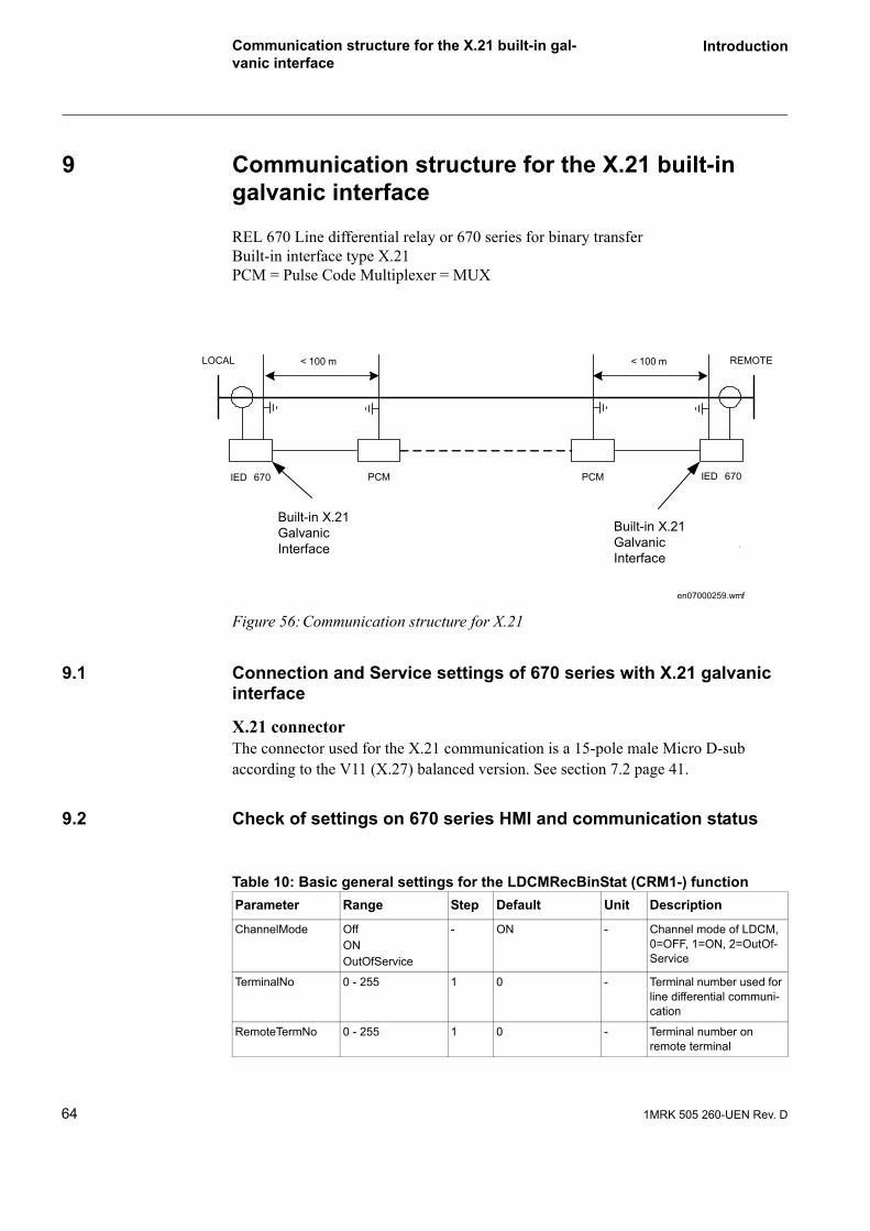
Communication structure for the X.21 built-in gal-vanic interface
Introduction
9 Communication structure for the X.21 built-in galvanic interface
REL 670 Line differential relay or 670 series for binary transferBuilt-in interface type X.21PCM = Pulse Code Multiplexer = MUX
Figure 56:Communication structure for X.21
9.1 Connection and Service settings of 670 series with X.21 galvanic interface
X.21 connectorThe connector used for the X.21 communication is a 15-pole male Micro D-sub according to the V11 (X.27) balanced version. See section 7.2 page 41.
9.2 Check of settings on 670 series HMI and communication status
LOCAL REMOTE< 100 m< 100 m
IED 670 PCM PCM IED 670
.
Built-in X.21GalvanicInterface
Built-in X.21GalvanicInterface
en07000259.wmf
Table 10: Basic general settings for the LDCMRecBinStat (CRM1-) functionParameter Range Step Default Unit Description
ChannelMode OffONOutOfService
- ON - Channel mode of LDCM, 0=OFF, 1=ON, 2=OutOf-Service
TerminalNo 0 - 255 1 0 - Terminal number used for line differential communi-cation
RemoteTermNo 0 - 255 1 0 - Terminal number on remote terminal
64 1MRK 505 260-UEN Rev. D
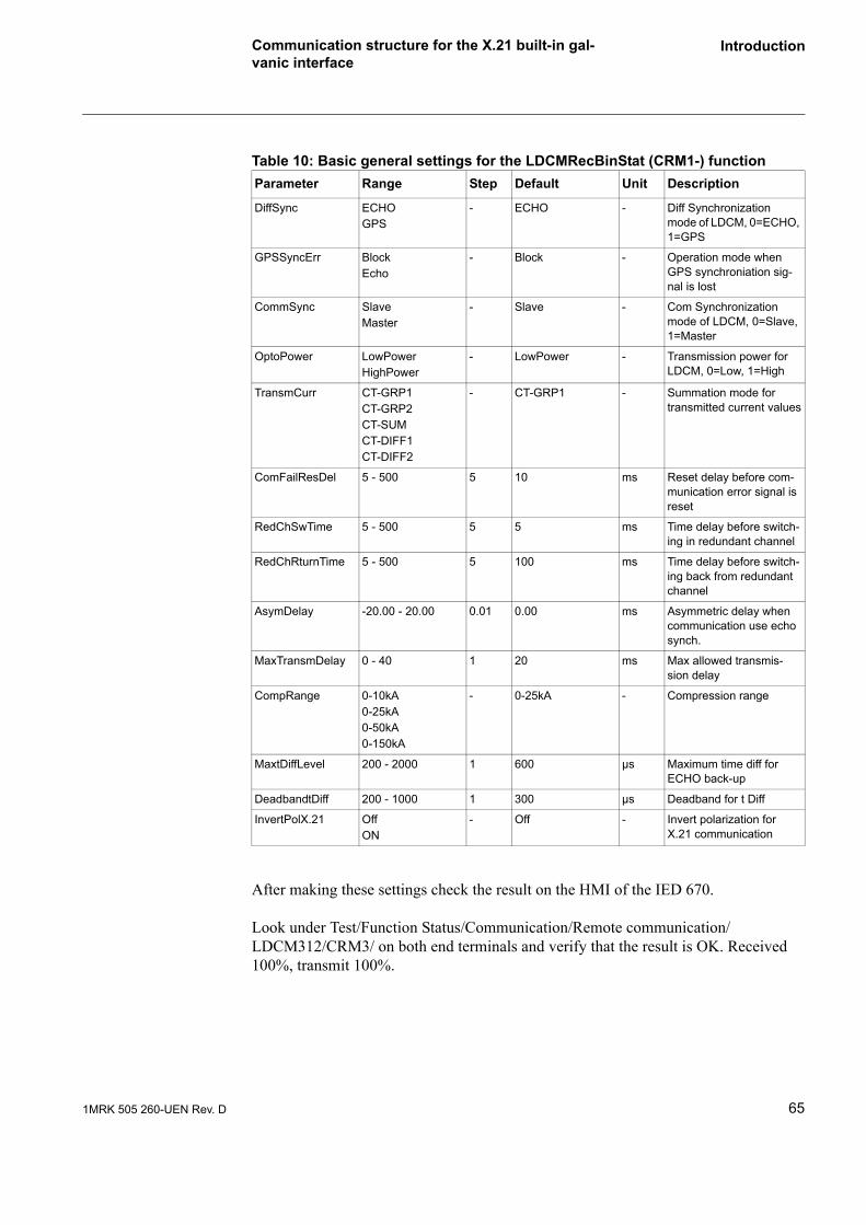
Communication structure for the X.21 built-in gal-vanic interface
Introduction
After making these settings check the result on the HMI of the IED 670.
Look under Test/Function Status/Communication/Remote communication/ LDCM312/CRM3/ on both end terminals and verify that the result is OK. Received 100%, transmit 100%.
DiffSync ECHOGPS
- ECHO - Diff Synchronization mode of LDCM, 0=ECHO, 1=GPS
GPSSyncErr BlockEcho
- Block - Operation mode when GPS synchroniation sig-nal is lost
CommSync SlaveMaster
- Slave - Com Synchronization mode of LDCM, 0=Slave, 1=Master
OptoPower LowPowerHighPower
- LowPower - Transmission power for LDCM, 0=Low, 1=High
TransmCurr CT-GRP1CT-GRP2CT-SUMCT-DIFF1CT-DIFF2
- CT-GRP1 - Summation mode for transmitted current values
ComFailResDel 5 - 500 5 10 ms Reset delay before com-munication error signal is reset
RedChSwTime 5 - 500 5 5 ms Time delay before switch-ing in redundant channel
RedChRturnTime 5 - 500 5 100 ms Time delay before switch-ing back from redundant channel
AsymDelay -20.00 - 20.00 0.01 0.00 ms Asymmetric delay when communication use echo synch.
MaxTransmDelay 0 - 40 1 20 ms Max allowed transmis-sion delay
CompRange 0-10kA0-25kA0-50kA0-150kA
- 0-25kA - Compression range
MaxtDiffLevel 200 - 2000 1 600 µs Maximum time diff for ECHO back-up
DeadbandtDiff 200 - 1000 1 300 µs Deadband for t Diff
InvertPolX.21 OffON
- Off - Invert polarization for X.21 communication
Table 10: Basic general settings for the LDCMRecBinStat (CRM1-) functionParameter Range Step Default Unit Description
651MRK 505 260-UEN Rev. D
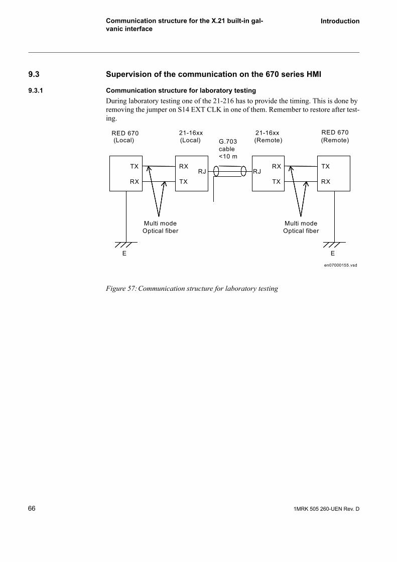
Communication structure for the X.21 built-in gal-vanic interface
Introduction
9.3 Supervision of the communication on the 670 series HMI
9.3.1 Communication structure for laboratory testingDuring laboratory testing one of the 21-216 has to provide the timing. This is done by removing the jumper on S14 EXT CLK in one of them. Remember to restore after test-ing.
Figure 57:Communication structure for laboratory testing
21-16xx
TX
RX
RX
TXRJ RJ
RX
TX
TX
RX
Multi mode Optical fiber
E
RED 670 RED 670(Local)
21-16xx
Multi mode Optical fiber
(Local) (Remote) (Remote)
E
G.703 cable <10 m
en07000155.vsd
66 1MRK 505 260-UEN Rev. D

PDH/SDH telecommunication system set-up with 670 series 64 kbit/s C37.94 interface to transceiver
Introduction
10 PDH/SDH telecommunication system set-up with 670 series 64 kbit/s C37.94 interface to transceiver type 21-219
The transceiver 21-219 can be used for both SDH or PDH systems.
10.1 Transceiver 21-219 service settings for SDH systemsNormally the SDH system with an accurate Master clock gives a high quality commu-nication with very low Bit Error Rate (BER10-9).
10.1.1 Service settings with the port for 21-219 synchronized to the SDH system mas-ter clockSetting up of a SDH system requires that the port for 21-219 is synchronized from the actual SDH network master clock. Thus the SDH telecommunication multiplexer (MUX) must be set to fulfil this. These settings are vendor dependent, but normally the SDH MUX has to be set for retiming and the format according G.704 framed, struc-tured, unstructured etc.
The format transparent cannot be used in SDH systems because no synchronization on the 21-219 SDH port is available.
Communication structure:
670 seriesTransceiver 21-219 Optical/electrical interface converterSDH MUX = Multiplexer in the SDH system
671MRK 505 260-UEN Rev. D

PDH/SDH telecommunication system set-up with 670 series 64 kbit/s C37.94 interface to transceiver
Introduction
Figure 58:Communication structure
Setting of clock source (slave mode)
In normal operation the 21-219 at both end of a line shall be configured for External clock, thus the configuration switch at the front shall be in position 0, the led 1, 2, 4, 8 shall all be off.
10.1.2 Service settings with the SDH/PDH port synchronized from one of the 21-219 transceivers (PDH system)The communication quality in PDH systems are normally not as good as in SDH sys-tems due to less stable clocks as Master. The bit error rate is normally BER 10-6.
Set-up as PDH system requires that the synchronization is provided from an external source, for example one of the 21-219 transceivers. Thus the SDH MUX must be set not to interfere with the synchronization. This setting is normally fulfilled by setting the SDH MUX in transparent mode.
Communication structure:
670 series Protection/control relayTransceiver 21-219 Optical/electrical interface converterSDH MUX = Multiplexer in the SDH system
LOCAL REMOTE<10m<10m
RED 670 Transciever21-219
SDHMUX
SDHMUX
Transciever21-219
RED 670
Multi-modeFibre optic<3.5 km
Multi-modeFibre optic<3.5 kmGalvanic
connectionInterfaceG.703 E1
(2MB)
GalvanicconnectionInterfaceG.703 E1
(2MB)
SDHMaster
Slaves Slaves (External clock)
en07000156.vsd
G704 (framed etc.)
68 1MRK 505 260-UEN Rev. D

PDH/SDH telecommunication system set-up with 670 series 64 kbit/s C37.94 interface to transceiver
Introduction
Figure 59:Communication structure
Setting of clock source (Master - slave mode)
Local end Master 21-219; In normal operation the 21-219 master should be set for Internal clock. Thus the configuration switch at the front shall be in position 1 and LED 1 shall be lit. The LED 2, 4, 8 shall all be off.
Remote end Slave 21-219; In normal operation the 21-219 slave shall be configured for External clock. Thus the configuration switch at the front shall be in position 0. The LED 1, 2, 4, 8 shall all be off.
Both 670 series devices shall be set as slaves.
Note that the differential protection clock is a separate issue not involved in communi-cation and always is set as Master for the differential protection, even if the differential protection is configured Master - Slave.
LOCAL REMOTE<10m<10m
RED 670 Transciever21-219
SDHMUX
SDHMUX
Transciever21-219
RED 670
Multi-modeFibre optic<3.5 km
Multi-modeFibre optic<3.5 kmGalvanic
connectionInterfaceG.703 E1
(2MB)
GalvanicconnectionInterfaceG.703 E1
(2MB)
SlaveSlaves (External clock)
en07000157.vsd
Transparent21-219Master
691MRK 505 260-UEN Rev. D

PDH/SDH telecommunication system set-up with 670 series 64 kbit/s C37.94 interface to transceiver
Introduction
10.1.3 Service settings of transceiver 21-219 G.703 E1 2 MbitThere is only one setting that is required. The 21-219 has to be set for external or inter-nal clock, depending on configuration of the telecomsystem.
Figure 60:21-219 Fiber optic IEEE C37.94 G.703 E1 Multiplexor
1 Functional ground
2 Power Supply IEC 320 connector
3 G.703 port
4 Fiber Optic Ports “Channel 0”
5 Fiber Optic Ports “Channel 1”
6 Status LEDs Fiber Optic Port “Channel 1”
7 Status LEDs Fiber Optic Port “Channel 0”
8 Reset button
9 Config-switch
10 Status LEDs G.703 and configuration
1 2en07000245.vsd
3
6710 8
54
9
en07000244.vsd
70 1MRK 505 260-UEN Rev. D

PDH/SDH telecommunication system set-up with 670 series 64 kbit/s C37.94 interface to transceiver
Introduction
Transceiver 21-219 has two channels which can be used for redundant communication, see Figure 61 below.
Figure 61:Protection system with redundant communication channels
10.1.4 ConfigurationNormal useNormally no configuration is needed!When two 21-219 are connected back-to-back, (E1 ports connected to each other), one of the 21-219 should be set to “Master mode”.
en07000241.vsd
711MRK 505 260-UEN Rev. D

PDH/SDH telecommunication system set-up with 670 series 64 kbit/s C37.94 interface to transceiver
Introduction
Config rotary switch
Figure 62:Rotary Switch
The rotary switch has 16 positions, (HEX_switch).
Figure 63:Rotary switch enlarged
At position 0 the arrow in the switch, visible through the adjusting hole, points straight down.
All configuration is done by setting the position of the “Config” rotary switch on the front panel. The “Config”-switch is operated with a small screwdriver. The switch has 16 positions. Every switch position is presented by the four LEDs 1, 2, 4,and 8, see figure 48. The LEDs forms a corresponding binary-value of the switch position. In the table below “X” marks a lit LED.
LED1
LED2
LED3
LED4
FUNCTION
(0H) External clock selected. “Slave mode”
X (1H) Internal clock selected. “Master mode”
en07000249.wmf en07000252.wmf en07000252.wmf
72 1MRK 505 260-UEN Rev. D
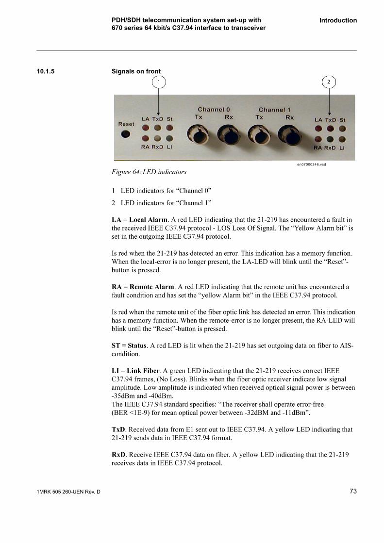
PDH/SDH telecommunication system set-up with 670 series 64 kbit/s C37.94 interface to transceiver
Introduction
10.1.5 Signals on front
Figure 64:LED indicators
1 LED indicators for “Channel 0”
2 LED indicators for “Channel 1”
LA = Local Alarm. A red LED indicating that the 21-219 has encountered a fault in the received IEEE C37.94 protocol - LOS Loss Of Signal. The “Yellow Alarm bit” is set in the outgoing IEEE C37.94 protocol.
Is red when the 21-219 has detected an error. This indication has a memory function. When the local-error is no longer present, the LA-LED will blink until the “Reset”-button is pressed.
RA = Remote Alarm. A red LED indicating that the remote unit has encountered a fault condition and has set the “yellow Alarm bit” in the IEEE C37.94 protocol.
Is red when the remote unit of the fiber optic link has detected an error. This indication has a memory function. When the remote-error is no longer present, the RA-LED will blink until the “Reset”-button is pressed.
ST = Status. A red LED is lit when the 21-219 has set outgoing data on fiber to AIS-condition.
LI = Link Fiber. A green LED indicating that the 21-219 receives correct IEEE C37.94 frames, (No Loss). Blinks when the fiber optic receiver indicate low signal amplitude. Low amplitude is indicated when received optical signal power is between -35dBm and -40dBm.The IEEE C37.94 standard specifies: “The receiver shall operate error-free (BER <1E-9) for mean optical power between -32dBM and -11dBm”.
TxD. Received data from E1 sent out to IEEE C37.94. A yellow LED indicating that 21-219 sends data in IEEE C37.94 format.
RxD. Receive IEEE C37.94 data on fiber. A yellow LED indicating that the 21-219 receives data in IEEE C37.94 protocol.
1 2
en07000246.vsd
731MRK 505 260-UEN Rev. D

PDH/SDH telecommunication system set-up with 670 series 64 kbit/s C37.94 interface to transceiver
Introduction
10.1.6 Detection of communication faults on 21-219There is supervision on the 21-219 which can be used for fault tracing.
There are two red light emitting diodes on the front of the 21-219, LA (Local Alarm) if there is some problem in 21-219, and RA (Remote Alarm) which is supervising the fiber optic link from the 21-219 to the 670 series, see section 10.1.5 page 67.
If 670 series has a communication fail alarm and there is no indication for LA or Ra on the 21-219, then the communication interruption is in the telecommunication system.
Grounding of 21-219
The interface protection circuitry in the 21-219 is based on the requirement that the tel-ecommunication multiplexer (MUX) interface is directly or low resistive grounded to the same ground as the grounding screw on the front of the 21-219. There is no over-turned protection in 21-219. If there is a potential difference between the 21-219 ground and the MUX ground it will result in a current flowing in the outer shield of the connecting cable that may damage the cable and degrade the system functionality with bite errors as a consequence.
Thus a correct grounding is essential, with the coaxial cables outer shield grounded to the chassi via the BNC contacts at both ends, see Figure 65.
Figure 65:Coaxial cables outer shield grounded to the chassi at both ends
en07000158 .vsd
Transceiver21-219
TX
R XSD HM U X
R X
TX
BN C contacts w ith the screen connected directly to chassi (ground )
M ake sure that the boxes are properly grounded , e.g . to a grounded fram e , w ith connections as short as possib le .
Im portant: Pow er supply from the sam e battery .
G rounding screw on front
C oaxia l cables
< 10 m
74 1MRK 505 260-UEN Rev. D

PDH/SDH telecommunication system set-up with 670 series 64 kbit/s C37.94 interface to transceiver
Introduction
Communication settings of 670 series connected to 21-219
The same setting as for 21-216 are used, see Section 10.1.3 page 70.
Communication structure for laboratory testing
During laboratory testing back-to-back one of the 21-219 must be set as Master. This is done by turning the configuration switch to pos 1 "EXT CLK" on one of them, LED 1 shall be lit and LED 2, 4, 8 shall be off.
751MRK 505 260-UEN Rev. D

Communication check/fault tracing Introduction
11 Communication check/fault tracing
11.1 Information available on the HMIOn the HMI of RED670 and the 670 series, the status of the remote communication can be supervised. The available information is also useful at fault tracing.
The information on the HMI can be found in the following HMI tree on the RED670 front.
Enter
-Test
- Function status
-Communication
-Remote communication
-LDCM (slot); Line Differential Communication Module
- CRM (no 1-4) Communication remote multi (analogue + binary)
or
- CRB (no 1-4) Communication remote binary (only binary-192 BI/BO)
SMT/ CRM and CRB: Signal Matrix Tool connection number to connect information to for example the event recorder.
11.1.1 Example of HMI info for transmission delay and asymmetry.
ECHO mode
Settings in IED A Settings in IED B
asymDelay -3.10 ms asymDelay 3.10
76 1MRK 505 260-UEN Rev. D

Communication check/fault tracing Introduction
WindowRemote communication/LDCM(slot)/CRM for RED670 and /CRB for the 670 series
Service value in IED A Service value in IED B
transmDelay 0.400 ms transmDelay 3.50
asymDelay -3.10 (same as setting) asymDelay 3.10 (same as setting)
In GPS mode the actual values are shownGPS mode
Service values in IED A Service values in IED B
transmDelay 0.4 ms transmDelay 3.500 ms
asymDelay -3.1 ms asymDelay 3.100 ms
HMI Info Signal Name SMT-CRM
SMT-CRB
Normal(Example)
Faulty(Example)
Specification
TransmDelay in Echo mode 1)
2 ms - Time Round trip delay/2 + set asym-metric delay
Transmission delay in GPS mode 1)
2 ms Time Actual transmission delay + measured asymmetric delay (+or -)
NoOfShInterr 50 - Counter No of short interruptions, 20-50 ms
NoOfMEDInterr 10 - Counter No of medium interruptions, 50-200 ms
NoOfLongInterr 5 - Counter No of long interruptions, >200 ms
CommStatus OK NoRXD Status Communication status/no of received messages
COMFAIL 0 1 Status Communication failure (>set delay 100 ms in service, 5-10 ms for fault tracing.)
19 19
NoOfTXD 100.000 <100 Status % No of sent messages
NoOfRXD 100.000 <75* Status % No of received messages
Ybit 0 1 Status Detected error in incoming message in remote end
13 13
AsymDelay 1) 0,5 ms - Setting/GPS ms
Asymmetric delay (Setting in echo mode or measured with GPS timing.)
ECHO mode
771MRK 505 260-UEN Rev. D

Communication check/fault tracing Introduction
* Around 75 % RXD is typical if for example two Master clocks are present in the communication system
** Only in RED670
11.2 Detection of communication faults on Fibersystem transceiver type 21-216 C37.94/G.703 64 kbit/s modem.There is supervision on the 21-216 which can be used for fault tracing, see section 8.7.
There are two red light emitting diodes on the front of the 21-216, LA (Local Alarm), there are some problem in 21-216 and RA (Remote Alarm) which is supervising the fiber optic link from the 21-216 to the 670 series.
NOCARR 0 1 No carrier is detected in the incoming message.Group signal - Logical OR for:
• LINK_LOST No input data stream at the optical receiver
• SYNC_LOST The clock synchronization is lost
• C37 ERROR Error at the C37.94 fiberoptic receiver (Faulty format)
25 25
NOMESS 0 1 Status No start and stop flags in incoming message
24 24
ADRERR 0 1 Status Incoming message from non-valid address
14 14
LNGTHERR 0 1 Status Incorrect length for the incom-ing message
23 23
CRCERROR 0 1 Status CRC-error in incoming mes-sage
15 15
TRDELERR** 0 1 Status Transmission delay error, > 40 ms
16 N.A**
SYNCERR** 0 1 Status Error in echo timing synchroni-zation
17 N.A**
REMCOMFAIL 0 1 Status Error in received message at remote end
18 18
REMGPSER** 0 1 Status Error in GPS synchronization at local or remote end
20 N.A**
SUBSTITU** 0 1 Status Link error, differential protec-tion blocked. Analogue values are substituted with zero, ref. disturbance recorder.
21 N.A**
LOWLEVEL 0 1 Status Low signal level in the receive link
26 26
HMI Info Signal Name SMT-CRM
SMT-CRB
78 1MRK 505 260-UEN Rev. D
Communication check/fault tracing Introduction
If IED 670 has a communication fail alarm and there is no indication for LA or Ra on the 21-216, then the communication interruption is in the telecommunication system.
11.3 Detection of communication faults on Fibersystem transceiver type 21-219 C37.94/G.703 G.703 E1 2 Mbit/s modem There is supervision on the 21-219 which can be used for fault tracing, see section 8.7.
There are two red light emitting diodes on the front of the 21-219, LA (Local Alarm), there are some problem in 21-219 and RA (Remote Alarm) which is supervising the fiber optic link from the 21-219 to the 670 series.
If IED 670 has a communication fail alarm and there is no indication for LA or Ra on the 21-219, then the communication interruption is in the telecommunication system.
11.4 Detection of communication faults by loop back tests.A very efficient way to trace the origin of communication problems is to make so called loop-back tests, that is to make a loop back to the local RED670 or 670 series products at various points in the communication system. The loop back tests involve both fiberoptic loop-back and galvanic cable loop-back, depending on actual point in the communication system.
Loop back test sequence.
Block the trip circuits.
Set the local relay and the remote relay with the same address.Setting of the Line Differential Communication module- LDCM- general settings
- communication- LDCM communication
-LDCM (slot no) - CRM(no) or CRB(No) for the 670 series
Terminal No [ ]Remote terminal No same [ ]Echo Synchronization On or OffGPS synchronization Off or On
The synchronization method shall be the same in the loop-back tests as in actual serv-ice.
Note:After loop back test, always restore the original terminal numbers. The same terminal number in both ends can cause an unwanted trip. If the relay has been in testmode, please check that local trip is reset before leaving test mode
791MRK 505 260-UEN Rev. D

Communication check/fault tracing Introduction
Perform Loop back tests at consecutive points in the communication system.The number of test will depend on the actual communication system, and number of channels.Fibersystem transceiver 21-216 will be connected to a 64 kbit PDH Multiplexer. Fibersystem 21-219 is normally connected directly to a 2 Mbit SDH multiplexer, reducing the number of interface points for the loop-back test.
Figure 66:Fiberoptic or galvanic loop-back
Test 1. Connect RX and TX directly on the actual LDCM with a fiberoptic loop.Check that the communication is OK on the HMI, see 11.1 page 70.
If there is more then one LDCM (max 4) on the local RED670, the test must be repeated for each channel
Test 2- to Test N. Loop back RX+ to TX+ and RX- to TX-. Loop back in respective interface points one by one in the communication system. Check the communication information on the HMI for each interface point, see 11.1 above. If no fault is found, Test 1 and Test 2 should be repeated in inverse order from the remote end.
Note:For loop-back tests with X21 galvanic interface special procedures and equipment is needed. Contact your local ABB representative.
80 1MRK 505 260-UEN Rev. D

Sample specification of communication requirements for differential protection RED670 and the 670 series protection and control terminals in digital telecommunication networks
Appendix 1
Sample specification of communication requirements for differential protection RED670 and the 670 series protection and control terminals in digital telecommunication networksThe communication requirements are based on echo timing.
Bit Error Rate (BER) according to ITU-T G.821, G.826 and G.828
• <10-6 according to the standard for data and voice transfer
Bit Error Rate (BER) for high availability of the differential protection
• <10-8-10-9 during normal operation• <10-6 during disturbed operation
During disturbed conditions, the trip security function in RED670 can cope with high bit error rates up to 10-5 or even up to 10-4. The trip security can be configured to be independent of COMFAIL from the differential protection communication supervi-sion, or blocked when COMFAIL is issued after receive error >100ms. (Default)
Synchronization in SDH systems with G.703 E1 or IEEE C37.94
The G.703 E1, 2 Mbit shall be set according to ITU-T G.803, G.810-13
• One master clock for the actual network • The actual port Synchronized to the SDH system clock at 2048 kbit• Synchronization; bit synchronized, synchronized mapping• Maximum clock deviation <±50 ppm nominal, <±100 ppm operational• Jitter and Wander according to ITU-T G.823 and G.825• Buffer memory <250 µs, <100 µs asymmetric difference• Format.G 704 frame, structured etc.Format.• No CRC-check
Synchronization in PDH systems connected to SDH systems
• Independent synchronization, asynchronous mapping.• The actual SDH port must be set to allow transmission of the master clock from
the PDH-system via the SDH-system in transparent mode• Maximum clock deviation <±50 ppm nominal, <±100 ppm operational• Jitter and Wander according to ITU-T G.823 and G.825• Buffer memory <100 µs• Format: Transparent • Maximum channel delay
811MRK 505 260-UEN Rev. D1MRK 505 260-UEN Rev. D

Sample specification of communication requirements for differential protection RED670 and the 670 series protection and control terminals in digital telecommunication networks
Appendix 1
• Loop time <40 ms continuous (2 x 20 ms)
IED 670 with echo synchronization of differential clock (without GPS clock)
• Both channels must have the same route with maximum asymmetry of 0,2-0,5 ms, depending on set sensitivity of the differential protection.
• A fixed asymmetry can be compensated (setting of asymmetric delay in built in HMI or the parameter setting tool PST).
IED 670 with GPS clock
• Independent of asymmetry.
82 1MRK 505 260-UEN Rev. D

Related documentsAppendix 2
Related documents
Documents related to RED670 Identity number
Operator’s manual 1MRK 505 184-UEN
Installation and commissioning manual 1MRK 505 185-UEN
Technical reference manual 1MRK 505 183-UEN
Application manual 1MRK 505 186-UEN
Buyer’s guide 1MRK 505 188-BEN
Connection diagram, Single breaker arr. Three phase tripping arr.
1MRK 002 801-BA
Connection diagram, Single breaker arr. Single phase tripping 1MRK 002 801-CA
Connection diagram, Multi breaker arr. Three phase tripping arr.
1MRK 002 801-DA
Connection diagram, Multi breaker arr. Single phase tripping arr.
1MRK 002 801-EA
Configuration diagram A, Single breaker with single or double busbars
1MRK 004 500-82
Configuration diagram B, Single breaker with single or double busbars
1MRK 004 500-83
Configuration diagram C, Multi breakers such as 1 1/2 or ring busbar arr.
1MRK 004 500-84
Configuration diagram D, Multi breakers such as 1 1/2 or ring busbar arr.
1MRK 004 500-85
Setting example 1, 230 kV Short cable line with 1 1/2 CB arr 1MRK 505 175-WEN
Documents related to REL 670 Identity number
Operator’s manual 1MRK 506 276-UEN
Installation and commissioning manual 1MRK 506 277-UEN
Technical reference manual 1MRK 506 275-UEN
Application manual 1MRK 506 278-UEN
Buyer’s guide 1MRK 506 280-BEN
Connection diagram, Single breaker arr. Three phase tripping arr.
1MRK 002 801-BA
831MRK 505 260-UEN Rev. D1MRK 505 260-UEN Rev. D

Related documentsAppendix 2
Connection diagram, Single breaker arr. Single phase tripping arr.
1MRK 002 801-CA
Connection diagram, Multi breaker arr. Three phase tripping arr.
1MRK 002 801-DA
Connection diagram, Multi breaker arr. Single phase tripping arr.
1MRK 002 801-EA
Configuration diagram A, Single breaker with single or double busbar, 3 pole tripping (A31)
1MRK 004 500-86
Configuration diagram B, Single breaker with single or double busbar, 1/3 pole tripping (A32)
1MRK 004 500-87
Configuration diagram C, Multi breaker such as 1 1/2 or ring busbar arr. 3 pole tripping (B31)
1MRK 004 500-88
Configuration diagram D, Multi breaker such as 1 1/2 or ring busbar arr. 1/3 pole tripping (B32)
1MRK 004 500-89
Setting example 1, 400 kV Long overhead power line with 1 1/2 CB arr. Quadrilateral characteristic.
1MRK 506 267-WEN
Setting example 2, Setting example 1, 400 kV Long overhead power line with 1 1/2 CB arr. Mho characteristic.
1MRK 506 291-WEN
Setting example 3, 230 kV Extremely long overhead power line, double bus, single CB arr. Quadrilateral characteristic.
1MRK 506 268-WEN
Setting example 4, 230 kV Extremely long overhead power line, double bus, single CB arr. Mho characteristic.
1MRK 506 292-WEN
Setting example 5, 132 kV Short overhead power line, double bus, single CB arr. Quadrilateral characteristic.
1MRK 506 269-WEN
Setting example 6, 132 kV Short overhead power line, double bus, single CB arr. Mho characteristic.
1MRK 506 290-WEN
Setting example 7, 70 kV power line on a resonance earth system. Double bus, single breaker arrangement.
1MRK 506 293-WEN
Setting example 8, 400 kV long series compensated line. 1 1/2 breaker arrangement.
1MRK 506 294-WEN
Documents related to REC 670 Identity number
Operator’s manual 1MRK 511 188-UEN
Installation and commissioning manual 1MRK 511 189-UEN
Technical reference manual 1MRK 511 187-UEN
Application manual 1MRK 511 190-UEN
Buyer’s guide 1MRK 511 192-BEN
84 1MRK 505 260-UEN Rev. D

Related documentsAppendix 2
Connection diagram, Single breaker 1MRK 002 801-FA
Connection diagram, Double breaker 1MRK 002 801-MA
Connection diagram, 1 1/2CB 1MRK 002 801-NA
Configuration diagram A, Single breaker arr. with single or double busbar
1MRK 004 500-90
Configuration diagram B, Double breaker arrangements 1MRK 004 500-91
Configuration diagram C, 1 1/2 breaker arr. for a full bay 1MRK 004 500-92
Documents related to RET 670 Identity number
Operator's manual 1MRK 504 087-UEN
Installation and commissioning manual 1MRK 504 088-UEN
Technical reference manual 1MRK 504 086-UEN
Application manual 1MRK 504 089-UEN
Buyer’s guide 1MRK 504 091-BEN
Connection diagram, Two winding transf. Single breaker arrangements
1MRK 002 801-LA
Connection diagram, Two winding transf. Multi breaker arrangements
1MRK 002 801-HA
Connection diagram, Three winding transf. Single breaker arrangements
1MRK 002 801-KA
Connection diagram, Three winding transf. Multi breaker arrangements
1MRK 002 801-GA
Configuration diagram A, Two winding transf. with single or double busbar but with a single breaker arr. on both sides (A30)
1MRK 004 500-93
Configuration diagram B, Two winding transf. in multi breaker arr. on one or both sides (A40)
1MRK 004 500-94
Configuration diagram C, Three winding transf. with single or double busbar but with a single breaker arr. on both sides (B30)
1MRK 004 500-95
Configuration diagram D, Three winding transf. in multi breaker arr. on one or both sides (B40)
1MRK 004 500-96
Configuration diagram E, Two or three winding transf., back-up protection package (A10)
1MRK 004 500-135
Configuration diagram F. Tap changer control package for two parallel transformers. (A25)
1MRK 004 500-140
851MRK 505 260-UEN Rev. D

Related documentsAppendix 2
Configuration diagram F. Tap changer control package for four parallel transformers. (A25)
1MRK 004 500-140
Setting example 1, 400/230 kV 500 MVA Transformer, YNyn connected
1MRK 504 083-WEN
Setting example 2, 132/230 kV 40 MVA Transformer, YNd1 connected
1MRK 504 084-WEN
Documents related to REB 670 Identity number
Operator’s manual 1MRK 505 179-UEN
Installation and commissioning manual 1MRK 505 180-UEN
Technical reference manual 1MRK 505 178-UEN
Application manual 1MRK 505 181-UEN
Buyer’s guide 1MRK 505 182-BEN
Documents related to REG 670 Identity number
Operator’s manual 1MRK 502 014-UEN
Installation and commissioning manual 1MRK 502 015-UEN
Technical reference manual 1MRK 502 013-UEN
Application manual 1MRK 502 016-UEN
Buyer’s guide 1MRK 502 019-BEN
Setting example 1MRK 502 020-WEN
Documents related to all IEDs Identity number
Connection and Installation components 1MRK 013 003-BEN
Test system, COMBITEST 1MRK 512 001-BEN
Accessories for IED 670 1MRK 514 012-BEN
Getting started guide IED 670 1MRK 500 080-UEN
SPA and LON signal list for IED 670, ver. 1.1 1MRK 500 083-WEN
IEC 61850 Data objects list for IED 670, ver. 1.1 1MRK 500 084-WEN
Generic IEC 61850 IED Connectivity package 1KHA001027-UEN
86 1MRK 505 260-UEN Rev. D

Related documentsAppendix 2
Fibersystem 21-216 manual at www.fibersystem.se
Fibersystem 21-219 manual at www.fibersystem.se
Protection and Control IED Manager PCM600 Installation sheet
1MRS755552
Engineering guide IED 670 products 1MRK 511 179-UEN
Buyer’s guide REG 216 1MRB520004-BEN
Note:Latest versions of the described documentation can be found at www.abb.com/substationautomation.
871MRK 505 260-UEN Rev. D

Related documentsAppendix 2
88 1MRK 505 260-UEN Rev. D

Contact us:
ABB ABSubstation Automation ProductsSE-721 59 Västerås SwedenPhone: +46 (0) 21 32 50 00Fax: +46 (0) 21 14 69 18
www.abb.com/substationautomation
1MR
K 5
05 2
60 U
EN R
ev. D
Power and productivityfor a better world TM