report documentation page · report documentation page form approved ... although the basic...
TRANSCRIPT

This article appeared in a journal published by Elsevier. The attachedcopy is furnished to the author for internal non-commercial researchand education use, including for instruction at the authors institution
and sharing with colleagues.
Other uses, including reproduction and distribution, or selling orlicensing copies, or posting to personal, institutional or third party
websites are prohibited.
In most cases authors are permitted to post their version of thearticle (e.g. in Word or Tex form) to their personal website orinstitutional repository. Authors requiring further information
regarding Elsevier’s archiving and manuscript policies areencouraged to visit:
http://www.elsevier.com/copyright

Report Documentation Page Form ApprovedOMB No. 0704-0188
Public reporting burden for the collection of information is estimated to average 1 hour per response, including the time for reviewing instructions, searching existing data sources, gathering andmaintaining the data needed, and completing and reviewing the collection of information. Send comments regarding this burden estimate or any other aspect of this collection of information,including suggestions for reducing this burden, to Washington Headquarters Services, Directorate for Information Operations and Reports, 1215 Jefferson Davis Highway, Suite 1204, ArlingtonVA 22202-4302. Respondents should be aware that notwithstanding any other provision of law, no person shall be subject to a penalty for failing to comply with a collection of information if itdoes not display a currently valid OMB control number.
1. REPORT DATE 2010 2. REPORT TYPE
3. DATES COVERED 00-00-2010 to 00-00-2010
4. TITLE AND SUBTITLE Essentials of Endodontic Microsurgery
5a. CONTRACT NUMBER
5b. GRANT NUMBER
5c. PROGRAM ELEMENT NUMBER
6. AUTHOR(S) 5d. PROJECT NUMBER
5e. TASK NUMBER
5f. WORK UNIT NUMBER
7. PERFORMING ORGANIZATION NAME(S) AND ADDRESS(ES) Post Graduate Endodontic Program,Harvard School of Dental Medicine,Boston,MA
8. PERFORMING ORGANIZATIONREPORT NUMBER
9. SPONSORING/MONITORING AGENCY NAME(S) AND ADDRESS(ES) 10. SPONSOR/MONITOR’S ACRONYM(S)
11. SPONSOR/MONITOR’S REPORT NUMBER(S)
12. DISTRIBUTION/AVAILABILITY STATEMENT Approved for public release; distribution unlimited
13. SUPPLEMENTARY NOTES
14. ABSTRACT
15. SUBJECT TERMS
16. SECURITY CLASSIFICATION OF: 17. LIMITATION OF ABSTRACT Same as
Report (SAR)
18. NUMBEROF PAGES
26
19a. NAME OFRESPONSIBLE PERSON
a. REPORT unclassified
b. ABSTRACT unclassified
c. THIS PAGE unclassified
Standard Form 298 (Rev. 8-98) Prescribed by ANSI Std Z39-18

Author's personal copy
Essentialsof EndodonticMicrosurgery
Stephen P. Niemczyk, DMDa,b,c,d,e,*
In his book Working in a Small Place Mark Shelton chronicles the efforts of a youngneurosurgeon, Dr Peter Jannetta, to introduce a radically new microsurgical techniquefor cranial nerve decompression. Pivotal to the technique was the use of the surgicaloperating microscope (SOM) for precise visualization and manipulation of the delicatestructures. What Dr Jannetta discovered was that not only was the use of the SOM inneurosurgery a rare event but also this particular piece of armamentarium was re-garded with disdain by the ‘‘Grand Old Men’’ of the profession. Programs were hesi-tant to implement this technology, and their residents were discouraged in its usebecause the senior staff members either felt estranged by the unfamiliarity with theSOM, or threatened by its presence. What Dr Jannetta realized was that, ratherthan trying to convince the grand old men of the merits of the SOM, he would workfrom within the system, slowly teaching his residents and wait for a new generation,his generation, to assume the role of senior staff members. He is quoted in thebook as saying ‘‘It takes twenty years for anything new to really catch on, not becauseit takes that long to convince the establishment, but because it takes that long for thereto be a changeover to people who have grown up with the new idea as beingaccepted.’’1 Today, all residency programs in neurosurgery require proficiency withthe SOM and microsurgery.
An interesting parallel is drawn when one examines the progression of the dentaloperating microscope (DOM) use in dentistry and, specifically, endodontics. Although
Movies can be viewed within this article at http://www.dental.theclinics.com, April 2010 issue.a Post Graduate Endodontic Program, Harvard School of Dental Medicine, Boston, MA, USAb Post Graduate Endodontic Program, Dental Division, Albert Einstein Medical Center,Philadelphia, PA, USAc Graduate Endodontic Program, National Naval Medical Center, Bethesda, MD, USAd United States Army Endodontic Program, Fort Gordon, GA, USAe 5100 Township Line Road, Drexel Hill, PA 19026, USA* 5100 Township Line Road, Drexel Hill, PA 19026.E-mail address: [email protected]
KEYWORDS
� Endodontic microsurgery � Ergonomics � Root end resection� Root end preparation � Root end filling
Dent Clin N Am 54 (2010) 375–399doi:10.1016/j.cden.2009.12.002 dental.theclinics.com0011-8532/10/$ – see front matter ª 2010 Elsevier Inc. All rights reserved.

Author's personal copy
presented as early as 1986 by Selden,2 it was not until the early 1990s that the DOMwas introduced to the profession and graduate-level endodontic programs.3–6 Theusefulness of the DOM in endodontics was viewed with similar skepticism by thesenior attendings of most programs for all the same reasons of their counterparts inneurosurgery. However, a concerted effort was made by a few enlightened individualswith foresight enough to recognize the advantages that microscopy could afford, andthey lobbied their cause until the late 1990s, when it was mandated that all graduateprograms and students demonstrate a proficiency in the use of the DOM. Before 1999,only 52% of the endodontists surveyed reported using the DOM.7 Compare that toa more recent survey,8 in which the age of the operator was compared with their usageof the DOM and it was found that the younger respondents (35 years old or younger)used the DOM 97% of the time for surgical and nonsurgical treatment. It is clear thatthe recent graduates are not only more comfortable with its use, but are also moreaccustomed to rendering treatment with the DOM. What is an interesting coincidenceis that endodontics is approaching the 20-year mark of the inception of the DOM intopractice; it would seem that Dr Jannetta’s prophecies extend to the dental professionas well!
Although the basic principles of endodontic surgery have not been dramaticallychanged, advances in armamentarium and microtechniques have attempted tokeep pace with the demands of today’s endodontic microsurgical environment:greater ergonomic flexibility, more efficient preparation and placement of the rootend filling (REF), and more biocompatibility of the materials used.
ANESTHESIA AND HEMOSTASIS
These 2 facets are inexorably linked because the effectiveness of the surgeon’sadministration preoperatively not only influences the comfort of the patient duringthe procedure but also the control of hemorrhage at the surgical site. Standardprotocol is divided into regional and local injections and are as follows:
1. The administration of a long-acting anesthetic agent such as bupivicaine (Mar-caine) as a block technique to obtain a sustained level of anesthesia beyond theduration of the surgery. For posterior surgeries this entails, for maxillary sites,a posterior superior and middle superior alveolar block; for posterior mandibularsites, an inferior alveolar nerve block supplemented with a mental nerve trunkblock. Maxillary anterior teeth are blocked using bilateral anterior superior alveolaror infraorbital injections, while mandibular anterior teeth receive bilateral mentalnerve blocks. All of these can be supplemented, as need be, with correspondingpalatal or lingual infiltrations of the same anesthetic.
In studies examining the effectiveness of lidocaine versus bupivicaine, it was shownthat lidocaine was faster in onset of lip numbness while bupivicaine resulted in longerduration.9 However, Gordon and colleagues10 have shown that administration of bu-pivicaine following surgical extractions resulted in decreased pain for longer periods oftime. By minimizing the peripheral barrage of peripheral nociceptive neurons, itreduced the development of central sensitization, thought to mediate partially thecentral component of allodynia and hyperalgesia. This postoperative effect can befurther enhanced by the preoperative administration of a nonsteroidal anti-inflamma-tory drug, resulting in statistically less postoperative discomfort and delay of onset ofpain.11,12 This peripheral block should be allowed to take effect (8–10 minutes) andsigns of adequate anesthesia noted before the next phase.
Niemczyk376

Author's personal copy
2. Once regional anesthesia has been achieved, then a local infiltration of lidocaine1:50,000 epinephrine is injected over the intended flap extent, concentrating thebulk of the infiltration over the surgical site. The injection speed is slow and steady(1–2 min/mL), allowing time for diffusion of the fluid and avoiding the formation ofa bolus accumulating in the submucosa.13 Done correctly, blanching will be evidentin the surrounding tissues, spreading throughout the flap and its perimeter. Careshould be taken to avoid injecting into skeletal muscle. Doing so will activate theb-adrenergic receptors, triggering vasodilation instead of constriction, causingundue hemorrhage on flap reflection and subsequent limited visibility of the surgicalsite.13,14
The outlined protocol is, of course, predicated on the systemic health of the patientand their ability to tolerate not only the surgical stress but also the cardiovascularimpact of the epinephrine in the selected anesthetic. Even in healthy patients a tran-sient tachycardia of short duration is not uncommon, but is usually well tolerated ifthe patient has been forewarned. However, in cases where underlying cardiovasculardiseases such as uncontrolled hypertension or history of recent cardiac surgery placethese patients at a higher risk, the surgeon would be prudent to consult with theirphysician before the procedure.
FLAP DESIGN
There are 3 basic flap designs; 2 are traditional mainstays (Triangular, Ochsenbein-Luebke) and the third a variation of a periodontal surgical incision, the papilla-baseflap.
The triangular flap design entails a full sulcular incision at least one tooth mesial anddistal of the intended surgical field. The blade tip is in contact with the crest of alveolarbone throughout the incision, severing the periosteum, and carried through the sulcusand into each interdental papilla. As each papilla is incised, it can be gently reflectedusing the scalpel blade to ensure that a complete cut has been made. A verticalreleasing incision is then made, originating at the line angle of the most anterior toothof the flap, and drawn apically parallel to the long axis of the adjacent roots (Fig. 1).
Fig. 1. Triangular (sulcular) flap. The solid red line indicates the sulcular incision from themesial of tooth #12 to the distal of tooth #15; the dotted line represents the verticalreleasing incision parallel to the root of tooth #11. Note the swelling in the mucobuccalfold near the MB apex of tooth #14.
Essentials of Endodontic Microsurgery 377

Author's personal copy
The soft tissue of the flap is then reflected, starting in the vertical releasing incision andproceeding coronally/distally/apically, undermining and releasing the periosteum untilfull reflection is achieved and the surgical site is uncovered.
The Ochsenbein-Luebke flap was the design of choice in the maxillary anterior whenthere were concerns about exposure of crown margins or gingival recession followingapical surgery (Fig. 2). This flap requires that the incision be contained within theattached gingiva, with at least 2 mm between the depth of the sulcus and the incisionline. The band of attached gingiva should also be wide enough so that the incision linedoes not cross the mucogingival junction into the alveolar mucosa. It is imperative thatthe sulcus depths be mapped, and there are specific instruments made for thispurpose called pocket markers, designed like college pliers, with one jaw configuredlike a periodontal probe and the other having a small ‘‘tooth’’ or projection on thetissue side of the jaw. These instruments are available in left- and right-side modelsto allow for correct orientation and adaptation to the tooth. The periodontal jaw isplaced against the facial surface of the crown of each tooth, inserted to the depthof the facial sulcus at 3 points, and the handles are gently squeezed to bring thepointed end of the opposite jaw into contact with the facial gingival; this createsa series of bleeding points apical to each crown, representative of the depth ofeach individual sulcus. The incision is made 2 to 3 mm apical to these bleeding points,in a scalloped fashion to mimic the contour of the respective gingival crests. The inci-sion is carried at least 1 to 2 teeth mesial and distal to the intended surgical site, witha vertical releasing incision terminating at both ends. The flap is reflected as with thetriangular design, starting at one end of the incision and progressing to the oppositeside. Although chosen to reduce the potential for exposed crown margins, this designis contraindicated in cases where a large apical lesion is present or there is aninadequate band of attached gingiva.15–20
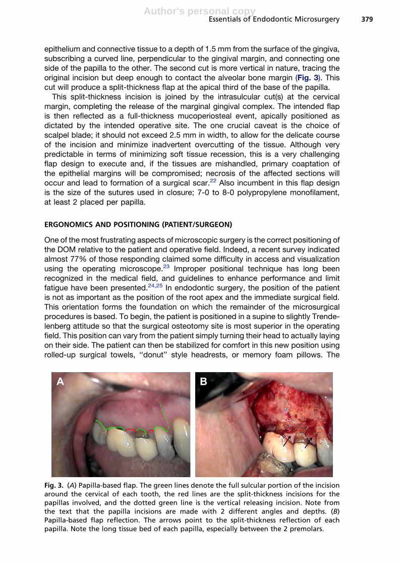
The papilla-base flap could be best termed a hybrid variation of a full sulcular andsplit-thickness incisions, and has been suggested to prevent the gingival recessionseen with the aforementioned 2 flap designs.21 This flap consists of 2 vertical releasingincisions, connected by intrasulcular incisions in the cervical areas of the plannedreflection concomitant with the papilla-based split-thickness variation. The split-thick-ness incision is accomplished in 2 steps: the first is a shallow cut, meant to sever the
Fig. 2. (A) Ochsenbein-Luebke flap. The solid red line is the scalloped incision in theattached gingiva. The purple dots, made with a Gentian Violet stick, denote the probingdepth plus 2 mm at the facial surface of each tooth in the proposed flap. The incisionconnects these dots together as one line, with vertical releasing incisions (dotted lines) atthe terminal ends of the flap. (B) Ochsenbein-Luebke flap. The suturing of the coapted‘‘points’’ of the flap correctly readapt the tissues. More sutures will be added to securethe flap (arrows).
Niemczyk378
Author's personal copy
epithelium and connective tissue to a depth of 1.5 mm from the surface of the gingiva,subscribing a curved line, perpendicular to the gingival margin, and connecting oneside of the papilla to the other. The second cut is more vertical in nature, tracing theoriginal incision but deep enough to contact the alveolar bone margin (Fig. 3). Thiscut will produce a split-thickness flap at the apical third of the base of the papilla.
This split-thickness incision is joined by the intrasulcular cut(s) at the cervicalmargin, completing the release of the marginal gingival complex. The intended flapis then reflected as a full-thickness mucoperiosteal event, apically positioned asdictated by the intended operative site. The one crucial caveat is the choice ofscalpel blade; it should not exceed 2.5 mm in width, to allow for the delicate courseof the incision and minimize inadvertent overcutting of the tissue. Although verypredictable in terms of minimizing soft tissue recession, this is a very challengingflap design to execute and, if the tissues are mishandled, primary coaptation ofthe epithelial margins will be compromised; necrosis of the affected sections willoccur and lead to formation of a surgical scar.22 Also incumbent in this flap designis the size of the sutures used in closure; 7-0 to 8-0 polypropylene monofilament,at least 2 placed per papilla.
ERGONOMICS AND POSITIONING (PATIENT/SURGEON)
One of the most frustrating aspects of microscopic surgery is the correct positioning ofthe DOM relative to the patient and operative field. Indeed, a recent survey indicatedalmost 77% of those responding claimed some difficulty in access and visualizationusing the operating microscope.23 Improper positional technique has long beenrecognized in the medical field, and guidelines to enhance performance and limitfatigue have been presented.24,25 In endodontic surgery, the position of the patientis not as important as the position of the root apex and the immediate surgical field.This orientation forms the foundation on which the remainder of the microsurgicalprocedures is based. To begin, the patient is positioned in a supine to slightly Trende-lenberg attitude so that the surgical osteotomy site is most superior in the operatingfield. This position can vary from the patient simply turning their head to actually layingon their side. The patient can then be stabilized for comfort in this new position usingrolled-up surgical towels, ‘‘donut’’ style headrests, or memory foam pillows. The
Fig. 3. (A) Papilla-based flap. The green lines denote the full sulcular portion of the incisionaround the cervical of each tooth, the red lines are the split-thickness incisions for thepapillas involved, and the dotted green line is the vertical releasing incision. Note fromthe text that the papilla incisions are made with 2 different angles and depths. (B)Papilla-based flap reflection. The arrows point to the split-thickness reflection of eachpapilla. Note the long tissue bed of each papilla, especially between the 2 premolars.
Essentials of Endodontic Microsurgery 379
Author's personal copy
surgeon then takes position at the head of the patient, the 11 to 12 O’clock orientation.The operator’s chair height is adjusted so that the angle formed between the thigh andlower part of the foot is a minimum of 90�, and the spine is comfortably straight. Thepatient’s chair is then raised or lowered so that the surgeon can maintain his or herelbows close to his body, passively bent at a neutral 90�. There are several companiesthat manufacture surgeon’s chairs that have elbow rests incorporated into them, af-fording support of the forearms and elbows. Once positioned, the surgeon’s armsand hands should not deviate from the core-centric position; this affords the greatestdexterity and precise micro-control, while limiting fatigue and strain trembling.26,27 Themicroscope is last positioned with the line of sight axis perpendicular to the soft tissuefield of the intended flap, and the binocular eyepieces adjusted to a comfortable heightrelative to the operator.
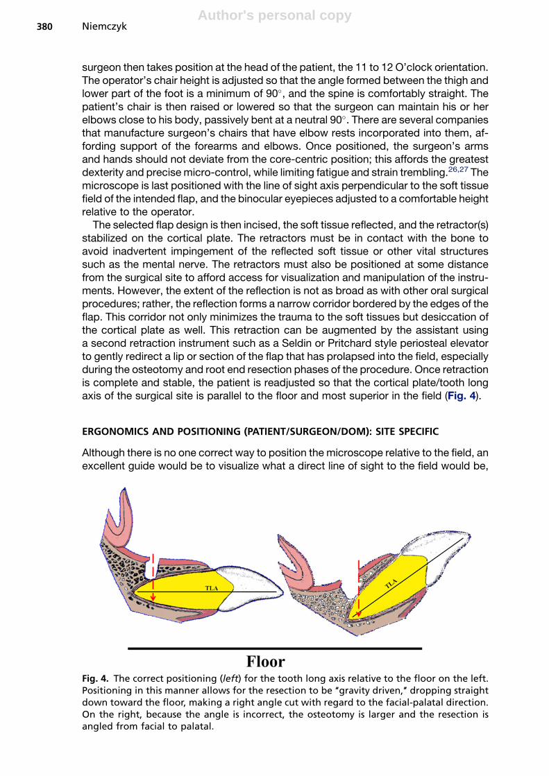
The selected flap design is then incised, the soft tissue reflected, and the retractor(s)stabilized on the cortical plate. The retractors must be in contact with the bone toavoid inadvertent impingement of the reflected soft tissue or other vital structuressuch as the mental nerve. The retractors must also be positioned at some distancefrom the surgical site to afford access for visualization and manipulation of the instru-ments. However, the extent of the reflection is not as broad as with other oral surgicalprocedures; rather, the reflection forms a narrow corridor bordered by the edges of theflap. This corridor not only minimizes the trauma to the soft tissues but desiccation ofthe cortical plate as well. This retraction can be augmented by the assistant usinga second retraction instrument such as a Seldin or Pritchard style periosteal elevatorto gently redirect a lip or section of the flap that has prolapsed into the field, especiallyduring the osteotomy and root end resection phases of the procedure. Once retractionis complete and stable, the patient is readjusted so that the cortical plate/tooth longaxis of the surgical site is parallel to the floor and most superior in the field (Fig. 4).
ERGONOMICS AND POSITIONING (PATIENT/SURGEON/DOM): SITE SPECIFIC
Although there is no one correct way to position the microscope relative to the field, anexcellent guide would be to visualize what a direct line of sight to the field would be,
Fig. 4. The correct positioning (left) for the tooth long axis relative to the floor on the left.Positioning in this manner allows for the resection to be ‘‘gravity driven,’’ dropping straightdown toward the floor, making a right angle cut with regard to the facial-palatal direction.On the right, because the angle is incorrect, the osteotomy is larger and the resection isangled from facial to palatal.
Niemczyk380

Author's personal copy
then position the line of sight of the microscope along that imaginary line. Inclinableoptics allow for the microscope to assume different vertical attitudes relative to 90�,and a shift of as little as 20� in either direction will enable the surgeon to look pastthe head of the handpiece to the end of a burr, or use direct vision to examine a re-sected root end. It is also imperative to have the microscope visual axis (MVA) parallelto the root long axis (RLA) at the selected resection level; if the observation position isskewed off-angle, the resection will mimic that angle (Fig. 5). This section explains thebasics of positioning for the microscope; more details concerning the actual root endprocedures follow in later sections. For the 4 major quadrants, the respective positionguidelines are presented.
MAXILLARY ANTERIOR
The head of the microscope is tilted slightly off from direct vertical, angling from thecrown of the tooth toward the apex (Fig. 6). This angle will alleviate the superimposi-tion effect of the head of the handpiece; bring the tip of the selected burr into view.Decortication of the intended apical site, if not already exposed by pathologic fenes-tration, is affected by a small round bur (#2–4) or other specialized bone bur (LindemanBone Bur). Care should be taken not to unintentionally gouge the selected root surfaceduring this discovery phase. Use of a nonaerosol producing handpiece, such as an
Fig. 5. The relationship of the root long axis (RLA) and the microscope visual axis (MVA). Ifthe microscope and, by extension, the surgeon are positioned in the same line as the longaxis of the root at the selected resection site, then the line of resection will be parallel to thesurgeon’s chest, an ergonomically reproducible path. This positioning will ensure the correctmesial-distal angulation. When a disparity exists, as shown on the right, the surgeon isguided by their body position and line of sight, not the position of the root tip, and anangled resection is made.
Essentials of Endodontic Microsurgery 381

Author's personal copy
Impact Air (Palisades Dental, Englewood, NJ, USA) will reduce the amount of occultspray in the field and improve visibility without compromising cooling of the bur andbone. Following identification of the selected apex, the osteotomy is enlarged toenable curettage of any lesion present and isolate the root tip from the surroundingsurgical crypt. How large an osteotomy should be is predicated on the native sizeof the lesion, adequate access for the armamentarium, and proximity to vital structuresuch as the mental nerve, mandibular canal, or maxillary sinus. In a phrase: it shouldbe as small as possible but as large as practical.
Once the root tip is isolated, the surgeon and DOM are repositioned so that they areparallel to the long axis of the root at the selected level of the resection, not the longaxis of the tooth, and the coronal-apical inclination is reestablished. With the direct lineof sight to the bur tip restored, the root end is resected (Movie 1, available along withall other movies cited here in the on-line version of this article at: http://www.dental.theclinics.com). Once resection is complete, the microscope is then angled fromapex to crown to allow for inspection of the resected root surface with direct vision(Movie 2). The angle will, of course, depend on the extent and quality of the retraction.Following the resection, the operator will be using micromirrors to more accuratelyassess the accuracy and completeness of the resected surface. This same anglewill also be used to visualize the root end preparation (see Movie 2).
MANDIBULAR ANTERIOR
The positioning is relatively the same, with a few notable exceptions:
(a) Positioning of the cortical plate parallel to the floor may not be possible; this shouldbe taken into account during the root end resection and preparation phases. In
Fig. 6. The correct inclination of the microscope and patient for maxillary anterior surgery.Position A and Movie 1 are for the resection; position B and Movie 2 are for the inspection,root end preparation (REP), and root end filling (REF).
Niemczyk382

Author's personal copy
many instances, rather than recline the patient to an uncomfortable angle, it maybe enough to have them elevate their chin slightly to affect this parallel position(Fig. 7) (Movies 3 and 4).
(b) The second angle, coming from the apex to the crown, again may be compro-mised by the limitations of the reflection and the angle of the patient, but the solu-tion may again be as simple as having the patient elevate the chin for a short periodof time to enable the correct line of sight.
MAXILLARY AND MANDIBULAR POSTERIOR
The limiting factor here is the ability of the patient to present the cortical plate parallelto the floor. Using rolled surgical towels or pillows to prop the back of the patient willallow them to comfortably lie on their side in the dental chair, affording a more favor-able attitude to the surgical site. An anesthesiologist’s ‘‘donut’’ or small pillow can alsobe placed under the patient’s head to gently cushion it in this new position. Failure toachieve this presentation of the surgical field often results in a misdirected ‘‘tunneling’’of the osteotomy, with the potential for inadvertently damaging adjacent roots orstructures (Fig. 8). Also, retraction in the most posterior of sites is inhibited by thexygoma or external oblique ridge, and may require repositioning of the retractor(s).Otherwise, the previous rules of positioning of the microscope hold true with respectto the osteotomy, root end resection/inspection, and preparation (Figs. 9 and 10)(Movies 5–8).
Fig. 7. The correct inclination of the microscope and patient for the mandibular anteriorsurgery. Position A and Movie 3 are for the resection; position B and Movie 4 are for theinspection, REP, and REF.
Essentials of Endodontic Microsurgery 383

Author's personal copy
Fig. 8. The magnified area of root apices teeth #13, #14, and #15 shows the correct osteot-omy approach (green arrow) for the distobuccal root of tooth #14. However, if the patient isfacing straight forward, the field of view is distorted at higher magnification, and theapproach angle is often too far mesial, resulting in a grazing or gouging of the MB root(red arrow). Turning the patient so that the cortical plate of the site is superior in the fieldalleviates this difficulty.
Fig. 9. The correct inclination of the microscope and patient for the maxillary posteriorsurgery. Position A and Movie 5 are for the resection; position B and Movie 6 are for theinspection, REP, and REF. Note the bow-tie effect on the resected root surface of this MBroot.
Niemczyk384

Author's personal copy
ROOT END RESECTION
This phase is perhaps the most pivotal of the surgical procedure, as errors here aremagnified with respect to the subsequent root end preparation and successful sealingof the apical extent of the root canal system. The carpenters’ axiom of ‘‘measuretwice, cut once’’ has great significance, as root structure cannot be replaced onceit has been removed, so careful consideration must be given to the length and angleof the resection process.
LENGTH
First and foremost are the restorative implications of the resection with regard tocrown-root ratio. There are histologic guidelines for how much of the root end shouldbe removed but if, in doing so, the integrity and stability of the remaining tooth iscompromised, alternative treatment options should be explored. If there is sufficientroot length in sound bone, then the amount of root apex that is removed is dictatedby the prevalence and distribution of the apical ramifications the surgeon hopes toeliminate. As the accompanying diagram shows (Fig. 11), a resection level of 3 mmfrom the anatomic apex will eliminate 93% of lateral canals and 98% of any other rami-fications such as deltas, fins, and so forth.28 Coupled with a root end preparationdepth of 3 mm, 6 mm of infectious etiology in the canal space will have been effectivelytreated. There are, however, 2 notable exceptions to this rule. First, if the level ofresection is such that it leaves a root geometry that is significantly curved at that level,then the root end preparation will be compromised (Fig. 12). The preparation tips, bydesign, are 3 mm long, and are not designed to follow curves like a root canal file.
Fig. 10. The correct inclination of the microscope and patient for the mandibular posteriorsurgery. Position A and Movie 7 are for the resection; position B and Movie 8 are for theinspection, REP, and REF. Note the harvesting of the root apex after resection, and the 2canals it demonstrates (one filled, one uninstrumented/filled).
Essentials of Endodontic Microsurgery 385

Author's personal copy
Hence, the preparation will be shallower than required because of the tip’s impact onthe curve or, if forced longer, can in fact perforate the external root surface. This situ-ation can be remedied by increasing the length of the resection past the curve,provided the overall length of the remaining portion of the root does not compromisethe crown-root ratio.
The other exception occurs when the root in question has undergone a resorptiveprocess, and is shorter than normal. In this instance, part of that ideal 3-mm length
Fig. 11. The relationship of resection level and canal ramifications eliminated in this canineapex. (Data from Kim S, Kratchman S. Modern endodontic surgery concepts and practice:a review. J Endod 2006;32:601–23.)
Fig. 12. The preoperative radiograph of tooth #3 demonstrates the dissimilar curves of theroots, and the correspondingly different angles of resection for each root apex. Note thatthe resection of the MB apex is slightly shorter so as not to impact the REP into the curve.The postoperative radiograph shows the REF to be well centered and to the correct depth.
Niemczyk386

Author's personal copy
has been eliminated involuntarily. Comparison of the root length of the contralateraltooth can assist in determining how much more of the apex needs to be removed, ifany. At the very least, the resorbed root apex would likely need to be flattened some-what to allow for efficient root end preparation and filling/finishing.
ANGLE
Before the introduction of the microscope, resected root ends were routinely beveled toenable the surgeon to visualize the resected surface(s). It was not uncommon for bevelsof 30�, 45�, or even greater to be placed because of ‘‘convenience.’’ This beveling wasmost often rendered by with a #4 to #6 round burr attached to a large, straight nose conehandpiece, such as a Stryker, or with a fissure burr in a conventional slow-speed hand-piece. This severe angle contributed to gross apical leakage and often failure of theapical surgery. In 1989, Tidmarsh and Arrowsmith29 examined the implications of thebeveled resection (45�–60�) with regard to dentinal tubule concentration in young andold teeth, and the depth of the effective retrograde seal. These investigators concludedthat the potential for leakage was greatest when the bevel was steep and the retrogradefilling did not extend deeper than the coronal aspect of the beveled surface. This conceptwas elaborated upon with the work of Gilheany and colleagues 1994.30 Twenty-sevensingle-rooted teeth were selected and their root apices were resected at 0�, 30�, and45�. Apical preparations were created and sequentially filled with a glass ionomer (KetacSilver). The apical microleakage and dentin permeability were measured by observingand quantifying the fluid flow in a hydraulic conductance apparatus as described byDerkson and colleagues in 1986.31 Gilheaney and colleagues concluded that: (1) theamount of leakage increased as the slope of the bevel increased; (2) increasing thedepth of the retrograde filling decreased the microleakage; and (3) optimum/minimum depths for the retrogrades were as follows: 0� 5 1 mm, 30� 5 2.1 mm,45� 5 2.5 mm (Fig. 13).
Bur selection for the root apex removal is almost a matter of personal choice.However, here are some guidelines based on the literature32–34:
Fig. 13. The impact of different bevel angles, and the amount of lateral leakage throughthe exposed dentinal tubules to the REF (blue triangles). The red triangle in the 45� bevelwould represent contaminated tubules left after such a resection in an infected rootapex. (Data from Gilheany PA, Figdor D, Tyas MJ. Apical dentin permeability and microleak-age associated with root end resection and retrograde filling. J Endod 1994;20:22–6.)
Essentials of Endodontic Microsurgery 387

Author's personal copy
(a) Straight or tapered carbide fissure configuration, long enough to span the depth ofthe apex, is advised. If a tapered fissure is chosen, the angle created by the tapershould be taken into account during the resection to maintain as close of a 0� bevelas possible.
(b) Avoid coarse diamond or crosscut fissure configurations as these create surfaceroughness and irregularities, making it difficult to finish the REF properly.
(c) Use of the bur in a high-speed handpiece with copious coolant is advised. It is alsorecommended that this coolant stream not be air driven, as this could potentiallyinduce an air embolism effect in the soft tissues of the surgical field. An exampleof such a handpiece is the Impact Air, available with or without fiber opticcapability.
The technique of the resection is not the ‘‘chainsaw’’ cutting of a tree trunk, butrather akin to the slicing of a piece of bread. In the former action, the coolant wouldfail to effectively reach the interface of the bur and tooth surface being cut, allowingfor the dentinal surface to become overheated and burned. By using the tip of thebur and making progressively deeper passes across the root tip surface, not onlywill the coolant flush and cool the resection cut but also the first few passes will createa ‘‘guide slot’’ in the root. If any adjustments to length or angle are required, they areeasily corrected at this time without undue, and irreversible, damage to the root. Thisguide slot also serves as a ‘‘pilot reference’’ to maintain the correct angle throughoutthe resection. Some operators prefer to shave the root end rather than resect it. Theauthor feels that this has the potential to cloud the issue of how much has reallybeen removed, and the shaving of an infected root end disperses just that muchmore pathogenic material into the surrounding crypt.
Once the apex (ices) has been removed, the first observation made should be of theresected tip cut surface (Fig. 14). This view will very often mirror the cut surface of theremaining root, offering a preview of what the surgeon is to expect in terms of numberof canals, filled or unfilled, isthmuses, fractures, and so forth. Such observations canalso reveal the smoothness of the cut, and whether the resection was complete;a jagged edge along the perimeter of the root usually indicates that portion of theroot being broken off, rather than cut cleanly. The situation is confirmed clinically byexamining the remaining root surface, either directly or in a micromirror.
Fig. 14. The picture on the left shows a root tip harvested after resection in this surgical re-treatment. The black stain near the MB canal is from the amalgam retrograde. Note thelong isthmus seen in this tip; it is the mirror image of what can be expected when the re-sected surface of the root is viewed. The picture on the right is the micromirror view ofthe resected surface; an exact replica of the observation made from the harvested root tip.
Niemczyk388

Author's personal copy
The remainder of the crypt is curetted to remove any remnants of soft tissue, sufficienthemostasis is either maintained or attained (explained in the following section), and theresected root end is disclosed with methylene blue, caries indicator, or other nontoxicdye. Subsequent observations of the root end(s) with a micromirror are made to assessthe conditions of the site: are there incomplete resections, indicated by an irregular peri-odontal ligament perimeter or ‘‘dog-eared’’ projection of dentin? Are there extra roots/canals present, evident by the staining or lack of it? Are there fractures or isthmuses,and what is their location and extent? All of these points need to be cataloged andresolved before any root end preparation. One interesting observation can be madewithout the aid of any disclosing solution. The author terms this the ‘‘Bow-Tie’’ effect,and it is readily evident on the wet, resected surface of the root (Fig. 15). These faint linesare not fractures, but represent the transitional line angles of the root dentin/tubules.Because the dentinal tubules refract light differently, depending on their orientation tothe light source, they will present a different appearance when viewed with incident
Fig. 15. (A, B) The radial dentin pattern in an anterior and posterior tooth, respectively.(C, D) The bow-tie effect. (C) The dentinal tubules of the transitional lines as they appearnaturally; (D) the tubules stained at the transitional line angles from a coronally leakingobturation.
Box 1
Water prism fluid effect
Movie 9 shows the prism effect of a clear fluid in the crypt of tooth #24. With theproper fluid level, it is possible to view the resected surface without the micromirror.Without altering the position of the DOM, the fluid is removed to reveal how muchof the light and view was being ‘‘bent’’ by the prism effect of the fluid.
Essentials of Endodontic Microsurgery 389

Author's personal copy
light. This appearance is the apical manifestation of what the author has termed ‘‘radialdentin’’ seen in the coronal chambers of dystrophically obliterated teeth.35 This ‘‘radialdentin’’ tracks back to the obliterated pulp space, serving as a map to the narrowedcanal. The radial dentin, apically, will point to the central location of the canal spaceand isthmus. This indication is especially important if the dye used did not discloseany canal/isthmus but the radial dentin suggests that it is present; the conclusionmust then be drawn that the resection level did not cut through, and thereby expose,the canal/isthmus enough to capture the dye. The clinical decision is then made to eitherroot end prepare according to the radial dentin outlines, or resect slightly more of theroot end to reveal the suspected space(s).
One last observation ‘‘trick’’ involves the principle of a prism and its ability to bendlight. This ‘‘water prism’’is especially useful in the mandibular anterior apices, wherespace in the crypt is often cramped and bleeding slightly. After resection, the cryptis rinsed with sterile saline until it runs clear but, rather than suction the site dry, thesaline is allowed to remain in the crypt. The level of the fluid can be adjusted throughjudicious suctioning with a microcannula, until the whole root end surface can beobserved. Not only will this facilitate the accurate positioning of the USREP (UltraSonicRoot End Preparation) tip without a micromirror, but the fluid itself offers a weak hemo-static tamponade effect (Movie 9; for movie description, see Box 1).
HEMOSTASIS
Before the USREP, the absolute hemostasis of the crypt needs to be achieved.Although the best hemostasis is achieved preoperatively with the anesthetic, a pro-longed surgery or systemic conditions may tax the effectiveness of the Lidocaine1:50,000. Most agents effect hemostasis by either by direct heme-agglutination orby triggering the natural clotting cascade of the patient. Of the two, the natural effectis preferable because it lasts for a relatively longer period of time. These agents, andtheir mode of action, are as follows.
Heme-Agglutination
SolutionsFerric sulfate or ferric subsulfate is the generic name for this agent. Depending on theconcentration of the chemical, it is also known by the trade names: Astringedent (Ul-tradent Products Inc, UT, USA) Viscostat, Stasis (Cut-Trol Ichthys Enterprises, Mobile,AL, USA), and Monsel’s.
Box 2
Ferric sulfate hemostasis technique
Movie 10. Placement of a pellet moistened with ferric sulfate into this grosslybleeding crypt. Note the immediate blackening of the occult blood and pellet.The end of the video shows a curette creating a fresh bleeding surface, and slough-ing of the necrotized tissue.
Box 3
Hemodette hemostasis technique
Movie 11. Placement of a blue Hemodette pellet and hemostasis after 3 minutes.
Niemczyk390

Author's personal copy
The most efficient delivery is via small microbrushes dipped into a dappen dish con-taining the solution, and then the moist tips are discretely applied to any small bleedingpoints. The agglutinated proteins coagulate and form a physical plug almost immedi-ately, and hemostasis is preserved so long as this plug remains undisturbed. Althoughextremely effective, all remnants of the ferric sulfate must be removed, and a freshbleeding surface reestablished (Movie 10; for movie description, see Box 2). Other-wise, significant and adverse effects on the osseous and soft tissue healing of thesite can be expected.36,37 The necrotizing effects, along with the difficulty in control-ling the distribution and complete elimination of this agent, strongly preclude its selec-tion in areas of neurovascular concern, namely, mandibular nerve, mental foramen,maxillary sinus, and floor of the nose.
GelsHemodette (20% buffered aluminum chloride gel, DUX Dental, Oxnard, CA, USA) isa water-soluble agent with agglutination properties similar to ferric sulfate, but withoutthe deleterious side effects. This agent is packaged as 2 impregnated cotton pelletswith an excess of gel in a sterile container resembling a prophy cup. Delivery is withthe cotton pellet or, using a microbrush, painting the crypt with the free gel. In additionto the heme-agglutination effect, the gel itself forms a sort of passive barrier to anyminor bleeder. The blue color makes it readily identifiable in the site, and it is easilyrinsed from the crypt with saline at the conclusion of the procedure (Movie 11; formovie description, see Box 3).
There are other gauze-based products such as ActCel (ActSys, Westlake Village,CA, USA), HemCon (HemCon Medical Technologies, Portland, OR, USA), and Blood-Stop (LifeSciencePlus, Palo Alto, CA, USA) that, when moistened with saline or bloodfrom the site, break down into a gel matrix, exerting the same combination of mild tam-ponade and heme-agglutination as the Hemodette, and that are just as easilyremoved. (Movie 12; for movie description, see Box 4).
Physiologic Clotting Agents
These products are, by and large, either bovine or porcine derived connective tissuematrices that initiate the patient’s own clotting cascade at the site. The advantage ofthis type of hemostasis is that it is usually longer lasting and more predictable in effect.Although Avitene (Avitene microfibrillar collagen hemostat, Davol Inc, Warwick, RI,USA) is the most effective and well known of this category, it is difficult to place andexpensive (Movie 13; for movie description, see Box 5). A reasonable substitute would
Box 4
ActCel hemostasis technique
Movie 12. Placement of the material at the mesiobuccal (MB) apex of tooth #19.Demonstrates the material turning to a jelly, and the excess is removed. After hemo-stasis is achieved, the crypt is rinsed and the REF is placed.
Box 5
Avitene hemostasis technique
Movie 13. Placement of the microfibrillar type, and the exceptional hemostasis after2 minutes in situ.
Essentials of Endodontic Microsurgery 391

Author's personal copy
be either CollaPlug or CollaTape (Zimmer Dental, Carlsbad, CA, USA). The tapedressing can be easily cut to fit the osteotomy, and the plug can be sliced into smalldiscs and placed over the bleeding sites. Gentle tamponade will accelerate the effect,although once the material is removed, the clotting effect will deteriorate within a fewminutes (Movie 14; for movie description, see Box 6).
ROOT END PREPARATION
Since their introduction by Carr in the early 1990s, the use of the USREP tip has refinedthe technique and practice of this phase of the surgery. USREP tips have evolved fromsmooth stainless steel tips of limited configurations to a myriad of multiple bends andangles, with coatings of diamond or zirconium nitride (Fig. 16). The safety, efficiency,and directions for use have been well investigated in the literature, and are consideredthe standard for root end preparations.38–42 There are several manufacturers of these
Fig. 16. USREP tips. (A, left to right) A stainless steel tip, a diamond-coated tip, and a zirco-nium nitride (ZN)-coated tip. (B) the assorted tip configurations for the ZN (ProUltraSurgicaltips, Dentsply-Tulsa Dental, Tulsa, OK, USA). (C) The tip diameter of the smaller #1 universaltip, and the larger #2 universal tip. (D) The different tip angles of the #3 and #4 posteriorsurgical tips. These different angles can accommodate different surgical presentation anglesof the root end without having to affect awkward handpiece positions.
Box 6
Colla Plug hemostasis technique
Movie 14. Placement of a small Colla Plug disc shows adequate hemostasis after 2minutes.
Niemczyk392

Author's personal copy
specialized tips, and most are interchangeable with regard to the attachment toa generating unit.
TECHNIQUE
Although the universal tips are designed for anterior teeth, and tri-angled tips forposterior locations, there is no rule as to where a particular tip can or cannot beused; the determining factor is access with the selected tip attached, and visibilityduring its use. In single canal roots, the tip is placed into the center of the gutta per-cha, if present, or the center of the canal space. The tip is energized, with enoughcoolant delivered through the tip to cool and flush the preparation site. The tip is al-lowed to passively seek its way down the canal, and this will happen readily if guttapercha is in the canal. Any high-pitched squeal from the tip indicates either binding ina small, uninstrumented canal, or that the tip is traversing off-angle. Visual inspectionwith a micromirror is prudent at this point to ensure that the preparation is remainingcentered in the canal. A groove in the buccal cortical plate, placed with the side of theUSREP tip, and parallel to the long axis of the root, will also aid in the correct angu-lation of the preparation, especially at higher magnifications (Movie 15; for moviedescription, see Box 7). The preparation is complete when the full depth of the tipis reached, usually 3 mm. In a root with multiple canals and an isthmus joiningthem (ie, the MB root of the maxillary first molar), the 2 canals (MB1 and MB2) areprepared separately to establish the correct angulation of the preparation, then theisthmus connecting them is prepped at the same angle (Movie 16; for movie descrip-tion, see Box 8). This action can be performed either directly or after tracing a smallgroove in the isthmus with the USREP tip dry. This latter procedure creates a troughthat will be easier to replicate once the tip is activated with coolant streaming into thesite, but caution should be exercised not to overheat the tip or the root end by pro-longed dry cutting. These coated tips are most efficient when they are new; forthat reason, it is the author’s opinion that they should be considered a single-useitem.
The identification and preparation of the isthmus is crucial to the sealing, and subse-quent successful healing, of the root end. Although some have designated 5 or 6 typesof isthmuses, they are actually permutations, based on the level of resection in a partic-ular root, of 2 basic types: partial and complete. First identified as a prominent surgical
Box 7
USREP tip guide
Movie 15. A reference notch is made on the cortical plate of tooth #14 MB root withthe side of the US tip. This notch, made parallel to the long axis of the root at theresection site, serves as a visual reference during root end preparation to maintainthe proper angle of the USREP tip.
Box 8
USREP technique
Movie 16 shows the preparation, using a new USREP tip, of the MB root of tooth #3.The MB1 and MB2 canals are prepared first, then the isthmus is prepared maintain-ing the identical angle between the 2 main canals. The preparation is viewed atcompletion in the micromirror.
Essentials of Endodontic Microsurgery 393

Author's personal copy
consideration in the MB root of a maxillary first molar (Fig. 17),43 it has evolved toinclude any root that has the potential to contain 2 or more canals,44,45 and shouldbe considered present until judged otherwise.
ROOT END FILLING
Although every restorative material has been used, at one time or another, as a REF,selection of today’s REF is predicated on whether it is contained within a root endpreparation (REP) or not. For situations whereby a REP can be created, the materialof choice is Mineral Trioxide Aggregate (MTA) (ProRoot MTA, Dentsply-Tulsa Dental,Tulsa, OK, USA). This compound is easy to mix, not cumbersome to place, andextremely biocompatible.46–53 MTA is manufactured in white and gray formulationsvirtually identical in composition. The only caveat is that the material must be placed
Fig. 17. In the MB root of a maxillary first molar with 2 canals, the table demonstrates anisthmus at the ideal resection length (3–4 mm) 100% of the time. (Data from Weller RN,Niemczyk SP, Kim S. Incidence and position of the canal isthmus. Part 1. Mesiobuccal rootof the maxillary first molar. J Endod 1995;21:380–3.)
Box 9
MAPS root end filling technique
Movie 17. Placement of MTA using a MAPS syringe. MTA is overfilled, the excesscompacted with the back of a Molt curette, and the surface of the MTA dried andwiped to contour with a microbrush. Micromirror view shows 2 canals in this buccalroot of tooth #12.
Niemczyk394

Author's personal copy
in a dry prep; excessive bleeding or moisture will wash the material away beforesetting. The most effective method to dry the REP is with a microtip attached toa Stropko Irrigator (J Bar B Co, Carefree, AZ, USA) syringe attachment. This devicereplaces the disposable tip of the triplex syringe, and the luer-lock end permits anysize luer-lock needle tip or cannula to be readily attached. With the air pressurereduced to 3 to 5 psi, this device can direct a concentrated stream of air or water tothe REP, either rinsing or drying it.
Placement of the MTA can be accomplished with a variety of instruments, from aninexpensive wipe-on block (Lee Endo Bloc, San Francisco, CA, USA) to a moresophisticated and costly syringe system (MAPS Roydent, Johnson City, TN, USA).(Movie 17; for movie description, see Box 9). Once the MTA is placed, a gentle steamof air from the Stropko is directed across the top of the REF to desiccate, and therebyfirm or ‘‘skin’’ the exposed surface of the material, After 20 to 30 seconds, the surfaceof the REF is firm enough to carve and any excess can be gently wiped away with a mi-crobrush (Movie 18; for movie description, see Box 10). The crypt may even be rinsedgently, provided the irrigant stream is not directed at the REF.
In instances whereby the depth of a post precludes a normal REP, then a bondedrestoration such as Geristore (DenMat, Santa Maria, CA, USA) may be placed toseal the root end. The technique of using bonded restorations on unprepared rootends was introduced by Rud and colleagues,54–57 and has enjoyed a great measureof success. However, as with the MTA, it is technique sensitive with respect to mois-ture, and the osteotomy is often enlarged to create a ‘‘high and dry’’ exposure of the
Box 10
MTA air-dry technique
Movie 18. The soft excess MTA is dried with an indirect airstream from the StropkoIrrigator tip. Once dried, the MTA is condensed with a ball burnisher and the excessis removed with a microbrush. The crypt is flushed with saline, and examined witha micromirror.
Fig. 18. Preoperative radiograph of tooth #4 reveals a post placed nearly to the root apex,and a failing retrograde in place (arrow). A bonded restoration (Geristore) replaces theamalgam and is the REF of choice when a REP of conventional depth cannot be achieved.The postoperative radiograph reveals the faint radio-opacity of the REF, and the conven-tional surgery and REF on tooth #5.
Essentials of Endodontic Microsurgery 395

Author's personal copy
root end. After saucering the root end, it is isolated, etched, and primed. The Geristoreis a dual-cure material, so an orange filter should be placed between the DOM lightsource and the surgical site to prevent premature curing of the material. The REF iseither troweled or syringed onto the root end, the filter removed, and the materialcured with the appropriate light source, then contoured to the root outline (Fig. 18)(Movie 19; for movie description, see Box 11).
SUTURING/CLOSURE
After the site has been cleansed of all debris, the underside of the flap(s) is gentlyrinsed with sterile saline and coapted back to the original positions. A moistenedgauze is placed over the coapted tissue, and gentle pressure is applied for approxi-mately 5 minutes. This procedure effectively expresses any occult blood under theflap, and initiates a preliminary attachment of the tissues. The flap is secured witheither interrupted or sling sutures; the choice of type and size is dictated by the flapdesign and retention requirements. Postoperative instructions should include dietand hygiene restrictions, pain medication guidelines and, most importantly, chillingof the overlying facial surface with ice (preferably in a zip-lock bag wrapped witha moist washcloth). The application of cold controls the amount of swelling from therebound vasodilatation phase, and therefore reduces the postoperative potential fordiscomfort from swelling. Chilling should continue for the first 24 hours postoperatively(10–15 minutes on, 5 minutes off) except while sleeping. Suture removal, in uncompli-cated cases, is normally 1 to 3 days after the operation.
SUMMARY
Today, endodontic surgeons are able to render a level of service with confidence andgreat precision that 20 years ago would have seemed unattainable by any standard.The development of a sophisticated armamentarium, groundbreaking techniques, andthe willingness to embrace them is the future of the specialty. The next 20 years shouldeclipse anything previously dreamt of, if the last 20 are any barometer of things to come.
REFERENCES
1. Shelton M. Working in a very small place; the making of a neurosurgeon. NewYork: W.W. Norton & Company; 1989. p. 91–3.
2. Selden HS. The role of the dental operating microscope in endodontics. Pa DentJ 1986;53:36.
3. Selden HS. The role of the dental operating microscope in improved nonsurgicaltreatment of ‘‘calcified’’ canals. Oral Surg Oral Med Oral Pathol 1989;68:93.
4. Selden HS. The dental operating microscope and its slow acceptance. J Endod2002;28:206.
5. Pecora G, Andreana S. Use of dental operating microscope in endodonticsurgery. Oral Surg Oral Med Oral Pathol 1993;75(6):751.
6. Carr GB. Microscopes in endodontics. J Calif Dent Assoc 1992;20:55.
Box 11
Geristore root end filling technique
Movie 19. Placement of Geristore in the apex of tooth #4. Note the close proximityof the post to the restoration.
Niemczyk396

Author's personal copy
7. Mines P, Loushine R, WQest L, et al. Use of the microscope in endodontics:a report based on a questionnaire. J Endod 1999;25:755.
8. Kersten DD, Mines P, Sweet M. Use of the microscope in endodontics: results ofa questionnaire. J Endod 2008;34:804.
9. Hargreaves KM, Khan A. Surgical preparation: anesthesia and hemostasis.Endodontic Topics 2005;11:32–55.
10. Gordon SM, Dionne RA, Brahim J, et al. Blockade of peripheral neuronal barragereduces postoperative pain. Pain 1997;70:209.
11. Jackson DL, Moore PA, Hargreaves KM. Pre-operative non-steroidal anti-inflam-matory medication for the prevention of postoperative dental pain. J Am DentAssoc 1989;119:641.
12. Dionne RA. Suppresion of dental pain by the preoperative administration offlurbiprofen. Am J Med 1986;80:41.
13. Gutmann JL. Parameters of achieving quality anesthesia and hemostasis insurgical endodontics [review]. Anesth Pain Control Dent 1993;2:223.
14. Kim S, Retham S. Hemostasis in endodontic microsurgery. Dent Clin North Am1997;41:499–513.
15. Johnson BR, Witherspoon DE. Periradicular surgery. In: Cohen, Hargreaves,editors. Pathways of the pulp. 9th edition. St. Louis (MO): Mosby; 2006. p. 744–5.
16. Pitt Ford Thomas R. Surgical treatment of apical periodontitis. In: Orstavik, Pitt Ford,editors. Essential endodontology. London: Blackwell Science Ltd; 1998. p. 282–3.
17. Arens DE. Practical lessons in endodontic surgery, Part I, lessons 1–7. Illinois:Quintessence Publishing Company; 1998.
18. Arens DE, Adams WR, DeCastro RA. Endodontic surgery, Chapter 1: consider-ations and indications for endodontic surgery. Philadelphia: Harper & Row;1981. p. 1–13.
19. Gutman J, Harrison J. Surgical endodontics. St Louis (MO): Ishiyaku EuroAmer-ica, Inc; 1994. Chapter 6. p. 154–61.
20. Gutmann JL, Harrison JW. Posterior endodontic surgery: anatomical consider-ations and clinical techniques. Int Endod J 1985;18:8.
21. Velvart P. Papilla base incision: a new approach to recession-free healing of theinterdental papilla after endodontic surgery. Int Endod J 2002;35:453–60.
22. Velvart P, Peters CI, Peters OA. Soft tissue management: suturing and woundclosure. In: Trope M, editor, Endodontic topics, vol. 11. Copenhagen V(Denmark): Blackwell Munksgaard; 2005. p. 179–95.
23. Creasy JE, Mines P, Sweet M. Surgical trends among endodontists: the results ofa web-based survey. J Endod 2009;35:30.
24. Berguer R. Surgery and ergonomics. Arch Surg 1999;134:1011.25. Buffington CW, MacMurdo SD, Ryan CM. Body position affects manual dexterity.
Anesth Analg 2006;102:1879.26. Comes C, Valceanu A, Rusu D, et al. A study on the ergonomical working modal-
ities using the dental operating microscope (DOM). Part 1: ergonomic principlesin dental medicine. TMJ 2008;58(3–4):218.
27. Golenberg L, Cao A, Ellis RD, et al. Hand position effects on precision and speedin telerobotic surgery. Int J Med Robot 2007;3(3):217–23.
28. Kim S, Kratchman S. Modern endodontic surgery concepts and practice:a review. J Endod 2006;32:601–23.
29. Tidmarsh BG, Arrowsmith MG. Dentinal tubules at the root ends of apicectedteeth: a scanning electron microscopic study. Int Endod J 1989;22:184–9.
30. Gilheany PA, Figdor D, Tyas MJ. Apical dentin permeability and microleakageassociated with root end resection and retrograde filling. J Endod 1994;20:22–6.
Essentials of Endodontic Microsurgery 397

Author's personal copy
31. Derkson GD, Pashley DH, Derkson ME. Microleakage measurement ofselected restorative materials: a new in vitro method. J Prosthet Dent 1986;56:435–40.
32. Gutmann JL. Perspectives on root-end resection. J Hist Dent 1999;47(3):135–6.33. Morgan LA, Marshall JG. The topography of root ends resected with fissure burs
and refined with two types of finishing burs. Oral Surg Oral Med Oral Pathol OralRadiol Endod 1998;85:585.
34. Weston GD, Moule AJ, Bartold PM. A comparison in vitro of fibroblast attachmentto resected root ends. Int Endod J 1999;32:444.
35. Niemczyk SP. Seeing is believeing: the impact of the operating microscope onnonsurgical endodontic treatment. Pract Proced Aesthet Dent 2003;15:395–9.
36. Lemon RR, Steel PJ, Jeansonne BG. Ferric sulfate hemostasis: effect on osseouswound healing. I. Left in situ for maximum exposure. J Endod 1993;19:170.
37. Jeansonne BG, Lemon RR, Boggs WS. Ferric sulfate hemostasis: effect onosseous wound healing. II. With curettage and irrigation. J Endod 1993;19:174.
38. Gray GJ, Hatton JF, Holtzman DJ, et al. Quality of root-end preparations usingultrasonic and rotary instrumentation in cadavers. J Endod 2000;26:281.
39. Peters CI, Peters OA, Barbakow F. An in vitro study comparing root-end cavitiesprepared by diamond-coated and stainless steel ultrasonic retrotips. Int Endod J2001;34:142.
40. Taschieri S, Testori T, Francetti L, et al. Effects of ultrasonic root end preparationon resected root surfaces: SEM evaluation. Oral Surg Oral Med Oral Pathol OralRadiol Endod 2004;98(5):611–8.
41. De Bruyne MA, De Moor RJ. SEM analysis of the integrity of resected root apicesof cadaver and extracted teeth after ultrasonic root-end preparation at differentintensities. Int Endod J 2005;38:310.
42. Roy R, Chandler NP, Lin J. Peripheral dentin thickness after root-end cavitypreparation. Oral Surg Oral Med Oral Pathol Oral Radiol Endod 2008;105(2):263–6.
43. Weller RN, Niemczyk SP, Kim S. Incidence and position of the canal isthmus. Part1. Mesiobuccal root of the maxillary first molar. J Endod 1995;21:380–3.
44. Von Arx T. Frequency and type of canal isthmuses in first molars detected byendoscopic inspection during periradicular surgery. Int Endod J 2005;38:160.
45. Mannocci F, Peru M, Sherriff M, et al. The isthmuses of the mesial root of mandib-ular molars: a micro-computed tomographic study. Int Endod J 2005;38:558.
46. Torabinejad M, Pitt Ford TR, McKendry DJ, et al. Histologic assessment ofmineral trioxide aggregate as a root-end filling in monkeys. J Endod 1997;23:225.
47. Chong BS, Pitt Ford TR, Hudson MB. A prospective clinical study of mineraltrioxide aggregate and IRM when used as root-end filling materials in endodonticsurgery. Int Endod J 2003;36(8):520–6.
48. Bernab�e PF, Gomes-Filho JE, Rocha WC, et al. Histological evaluation of MTA asa root-end filling material. Int Endod J 2007;40(10):758–65.
49. Holland R, de Souza V, Nery J, et al. Reaction of dogs’ teeth to root canal fillingwith Mineral Trioxide Aggregate or a Glass Ionomer sealer. J Endod 1999;25:728.
50. Lindeboom JA, Frenken JW, Kroon FH, et al. A comparative prospective random-ized clinical study of MTA and IRM as root-end filling materials in single-rootedteeth in endodontic surgery. Oral Surg Oral Med Oral Pathol Oral Radiol Endod2005;100(4):495–500.
51. Saunders WP. A prospective clinical study of periradicular surgery using mineraltrioxide aggregate as a root-end filling. J Endod 2008;34(6):660–5.
Niemczyk398

Author's personal copy
52. Camilleri J, Montesin FE, Papaioannou S, et al. Biocompatibility of two commer-cial forms of mineral trioxide aggregate. Int Endod J 2004;37:699.
53. Tanomaru-Filho M, Luis MR, Leonardo MR, et al. Evaluation of periapical repairfollowing retrograde filling with different root-end filling materials in dog teethwith periapical lesions. Oral Surg Oral Med Oral Pathol Oral Radiol Endod2006;102(1):127–32.
54. Rud J, Munksgaard EC, Andreasen JO, et al. Retrograde root filling withcomposite and a dentin-bonding agent. 1. Endod Dent Traumatol 1991;7:118.
55. Rud J, Munksgaard EC, Andreasen JO, et al. Retrograde root filling withcomposite and a dentin-bonding agent. 2. Endod Dent Traumatol 1991;7:126.
56. Rud J, Rud V, Munksgaard EC. Long term evaluation of root filling with dentin-bonded resin composite. J Endod 1996;22:90.
57. Rud J, Rud V, Munksgaard EC. Periapical healing of mandibular molars after root-end sealing with dentine-bonded composite. Int Endod J 2001;34:285.
Essentials of Endodontic Microsurgery 399