report following technical investigation - · pdf fileincident summary ... 13 1 - immediate...
TRANSCRIPT
REPORT FOLLOWINGTECHNICAL INVESTIGATIONinto the collision (and resulting fire)between a coach and a HGVthat occurred on October 23rd 2015on Departmental Road No 17near the town of Puisseguin(South-West of France) July 2017


Land Transport Accidents
Investigations Bureau
Case n° BEATT-2015-014
Report following the technical investigationinto the collision (and resulting fire)
between a coach and a HGVthat occurred on October 23rd 2015
on Departmental Road n°17near the town of Puisseguin
(South-West of France)

Bordereau documentaire
Report commissioned by: Ministry for an Ecological and Solidarity Transition (MTES)
Report compiled by: Land Transport Accidents Investigations Bureau (BEA-TT)
Document Title: Report following the technical investigation into the collision (and resulting fire)between a coach and a HGV on October 23rd 2015on Departmental Road 17 near Puisseguin(33)
IRSN N°: EQ-BEAT--17-6--FR
Suggested keywords: coach, fire
Photo and graphic design credits:— AF: AFHYMAT;— BEA-TT: Land Transport Accidents Investigations Bureau— CL: Christophe Ledon, accident examiner;— EV: EvoBus France;— FB: Francis Bréville, automobile expert;— Gend. : gendarmerie (police);— IV: IVECO;— XG: Xavier Gargasi, fire expert.

Legal Notice
The technical investigation featuring in this report was carried out inaccordance with Articles L. 1621-1 - 1622-2 and R. 1621-1 - 1621-26 ofthe French Transport Code, pertaining in particular to technical inquiriescarried out following a land transport accident or incident.
The sole objective of this investigation is to prevent future accidents fromoccurring by determining the circumstances and causes of the event andestablishing relevant safety recommendations. The report does not aim todetermine responsibility for the accident.
As a result, the use of this report for purposes other than accidentprevention may lead to erroneous interpretations of its contents.


TABLE OF CONTENTS
GLOSSARY..................................................................................................................................11
INCIDENT SUMMARY.................................................................................................................13
1 - IMMEDIATE ANALYSIS AND LAUNCH OF OFFICIAL INVESTIGATION............................15
1.1 - Circumstances of the accident.........................................................................................15
1.2 - Death and injury toll.........................................................................................................15
1.3 - Launch and organisation of the investigation..................................................................15
2 - BACKGROUND TO THE ACCIDENT....................................................................................17
2.1 - Weather Conditions..........................................................................................................17
2.2 - Departmental Road n°17.................................................................................................17
2.2.1 -Road characteristics............................................................................................................................. 17
2.2.2 -Road adhesion measurements.............................................................................................................19
2.2.3 -Traffic and Accident Rates.................................................................................................................... 19
3 - SUMMARY OF INVESTIGATIONS CARRIED OUT..............................................................21
3.1 - Situation at the scene as encountered by emergency services......................................21
3.1.1 -Position and condition of the vehicles...................................................................................................21
3.1.2 -Tyre tracks found on the road surface..................................................................................................22
3.1.3 -Infrastructural Damage.........................................................................................................................24
3.2 - Witness Statement Summaries........................................................................................24
3.2.1 -Witness statement from the coach driver..............................................................................................24
3.2.2 -Witness statements from coach passengers........................................................................................25
3.2.3 -Witness statements from motorists present at the scene of the accident.............................................27
3.3 - The coach.........................................................................................................................28
3.3.1 -Organisation of the excursion...............................................................................................................28
3.3.2 -The coach driver................................................................................................................................... 28
3.3.3 -Technical characteristics of the coach..................................................................................................29
3.3.4 -Expert assessment of the coach...........................................................................................................38
3.4 - The articulated lorry.........................................................................................................42
3.4.1 -The driver of the articulated lorry..........................................................................................................42
3.4.2 -Technical characteristics of the tractor unit...........................................................................................44
3.4.3 -Modifications made to the tractor unit following its factory release.......................................................49
3.4.4 -Technical characteristics of the semitrailer...........................................................................................55
3.4.5 -Assessment of the Tractor Unit.............................................................................................................56
3.4.6 -Expert analysis of the semitrailer and its components..........................................................................61
3.5 - Kinematic reconstruction of the accident.........................................................................63
3.5.1 -Final position of vehicles and tyre tracks on road surface....................................................................64
3.5.2 -Identification of impact points and directionality....................................................................................65

3.5.3 -Vehicle 3D Modelling............................................................................................................................ 66
3.5.4 -Results.................................................................................................................................................. 66
3.6 - Outbreak and spread of the fire.......................................................................................67
3.6.1 -Fuel supply sources.............................................................................................................................. 68
3.6.2 -The heat source at the origin of the blaze.............................................................................................73
3.6.3 -The hypothesis concerning what triggered the fire and caused it to spread.........................................73
3.7 - Current regulations for public transit vehicles in terms of layout, fire risk and design of exits..........................................................................................................................................74
3.7.1 -Tanks and auxiliary liquid fuel tanks......................................................................................................76
3.7.2 -Prevention of fire risks in coaches........................................................................................................76
3.7.3 -Design of coach exits............................................................................................................................ 76
3.7.4 -Interior lighting and emergency lighting for coaches.............................................................................77
3.8 - Emergency evacuation procedure...................................................................................77
3.9 - Similar accidents..............................................................................................................78
4 - ANALYSIS OF THE COURSE OF THE ACCIDENT AND RESCUE OPERATIONS............81
4.1 - The route of the vehicles before the accident..................................................................81
4.1.1 -The route of the articulated lorry...........................................................................................................81
4.1.2 -The route of the coach.......................................................................................................................... 81
4.2 - The collision and the ignition of the fire............................................................................81
4.3 - Evacuating the coach.......................................................................................................82
4.3.1 -Notification of emergency services.......................................................................................................82
4.3.2 -Assessment and location of victims......................................................................................................82
4.3.3 -Assessment of the means of assistance implemented.........................................................................83
5 - ANALYSIS OF CAUSES AND ASSOCIATED FACTORS, PREVENTIVE GUIDELINES.....84
5.1 - The pattern of causes and associated factors.................................................................84
5.2 - The signing for the bend..................................................................................................86
5.2.1 -Reminder of the findings.......................................................................................................................86
5.2.2 -Analysis................................................................................................................................................ 86
5.3 - Additional fuel tanks.........................................................................................................87
5.3.1 -Reminder of the findings.......................................................................................................................87
5.3.2 -Analysis................................................................................................................................................ 87
5.4 - The burning behaviour of coaches...................................................................................88
5.4.1 -Reminder of the findings.......................................................................................................................88
5.4.2 -Analysis................................................................................................................................................ 88
5.5 - The smoke extraction and evacuation of coaches...........................................................90
5.5.1 -Reminder of the findings.......................................................................................................................90
5.5.2 -Analysis................................................................................................................................................ 90
6 - CONCLUSIONS AND RECOMMENDATIONS......................................................................95
6.1 - Causes of the accident.....................................................................................................95
6.2 - Preventive guidelines.......................................................................................................95

Appendix 3: Aerial view of RD 17 in the area of the accident................................................101
Appendix 4: Cross-sectional horizontal and vertical alignment of RD 17 at the accident site................................................................................................................................................102
Appendix 5: Accident frequency rate on the RD 17 between 2010 and 2015.......................105
Appendix 6: Description of the coach’s heating and air conditioning systems......................106
Appendix 7: Extract from the safety data sheet for refrigerant R134a...................................110
Appendix 8: Extract from the safety data sheet for Glysantin G48........................................111
Appendix 9: Excerpts from the "TOTAL Diesel Premier" fuel safety data sheet....................112
Appendix 10: Coach Passenger Safety Awareness Booklet published in 2016 by the FNTV. 114

Glossary
➢ ABS: Anti-lock braking system
➢ ABS: Acrylonitrile butadiene styrene, a thermoplastic polymer that is often used inautomotive construction.
➢ AGVW: Authorised Gross Vehicle Weight
➢ DR: Departmental Road
➢ FNTV: National federation of passengers transport
➢ GVWR: Gross Vehicle Weight Rating
➢ HGV: Heavy Goods Vehicle
➢ IISR: Interministerial Directive on Road Signs
➢ MRP: Map Reference Point
➢ SCR: Selective Catalytic Reduction – a technique used to reduce emissions of nitrogenoxide from internal combustion engines.
11


Incident Summary
On October 23rd 2015, at around 7.30am, near the town of Puisseguin in the Girondedepartment of France (33), an articulated lorry (consisting of a tractor unit and an emptywood trailer) with two people on board, travelling on the Departmental Road number 17towards the town of Puisseguin, jack-knifed when navigating a right-hand bend andpassed into the opposite lane, colliding with a coach carrying 49 people which wastravelling in the opposite direction.
A fire broke out immediately after the crash and engulfed both vehicles.
The accident resulted in the deaths of 43 people (41 coach passengers and the twopeople travelling in the HGV), and caused injuries to 8 others who were able to escapefrom the coach (the driver and 7 passengers).
The direct cause of the accident was the loss of control of the HGV as it was navigating atight right bend, causing the vehicle to swerve into the left hand-lane and collide with acoach travelling in the opposite direction.
A fierce blaze broke out immediately after the collision. The coach was quickly engulfed inflames and filled with toxic black smoke.
Several factors played a role in the accident’s high death toll:
➢ the presence of an additional, non-regulary diesel tank installed behind the cabin of thetractor unit;
➢ the nature of the materials used for the coach’s interior fittings, their flammability andthe toxicity of the gases released via their combustion;
➢ the passengers’ difficulty in activating the coach’s smoke extraction devices;
➢ the passengers’ difficulty in using the coach’s two entrances and emergency exits;
➢ the absence of light inside the coach following the collision.
In light of these elements, the BEA-TT has drawn up, for the attention of the Ministry ofTransport’s Directorate of Energy and Climate, five recommendations regarding:
➢ the installation inspections for additional fuel tanks on vehicles;
➢ the improved fire-resistance of materials used in vehicle construction, and theintroduction of new industrial standards regarding the toxicity of gases released by thecombustion of these materials;
➢ the improvements to the opening mechanisms for smoke extraction devices, in order tomake them easier to use;
➢ the addition of emergency doors at the rear end of such vehicles, or failing this,extending the provisions of Decree n° 2015-1170, issued on September 22nd 2015(pertaining to accessibility in vehicles designated for use in providing inter-urban publictransport services) to all buses and coaches, and/or improving industry standardsregarding the opening mechanisms of emergency exit windows in order to make theminstantly manoeuvrable and easier to use in the event of an emergency evacuation ofthe vehicle.
13

➢ The reinforcement of existing legislation regarding “emergency lighting systems” forcoaches, so that safety equipment for emergency evacuations (and emergency lightingused to indicate vehicle evacuation routes) remain visible, especially in cases where thevehicle’s interior has become filled with opaque smoke.
In addition, without formulating any formal recommendations, the BEA-TT:
➢ has invited the roadways authority to study the possibility of reducing the maximumspeed limit to 50 km/h on this corner;
➢ has invited trade union bodies representing HGV drivers to make their members awareof the importance of respecting approved technical rules when installing fuel tanks;
➢ has invited the FNTV to complete the safety leaflet introduced in 2016 which indicatethe safety rules to be respected on board in the coach, as well as emergencyevacuation rules, by describing what to do in the event of a fire breaking out in thepassenger compartment of the coach.
14

1 - Immediate analysis and launch of official investigation
1.1 - Circumstances of the accident
On October 23rd 2015, at around 7.30am, near the town of Puisseguin in the Girondedepartment of France (33), an articulated lorry (consisting of a tractor unit and an emptywood trailer) with two people on board, travelling on the Departmental Road number 17towards the town of Puisseguin, jack-knifed when navigating a right bend and passed intothe opposite lane, colliding with a coach carrying 49 people which was travelling in theopposite direction.
A fire broke out immediately after the crash and engulfed both vehicles.
1.2 - Death and injury toll
The accident resulted in the deaths of 43 people (41 coach passengers and the twopeople travelling in the HGV), and caused injuries to 8 others (the driver and7 passengers of the bus).
1.3 - Launch and organisation of the investigation
In light of the circumstances of the accident, the Director of the Land Transport AccidentsInvestigations Bureau (BEA-TT) opened a technical investigation on the same day theaccident occurred (October 23rd 2015), under the provisions of Articles L. 1621-1 -L. 1622-2 of the French Transport Code.
BEA-TT investigators were rapidly deployed to the scene of the accident. There they metlocal magistrates and police officers responsible for the legal inquest into the accident.
They were given access to the vehicles, which had been sealed off as official evidence.
They were also given access to the judicial case files and to reports from four legalexperts commissioned in October 2015, as well as the main administrative and technicaldocuments necessary for their analysis.
They were unable to obtain copies of certain administrative and technical documentshaving been placed under seal. These pertain to the installation of the additional fuel tankbehind the cabin of the tractor unit, as well as certain original copies of photographs takenby judicial investigators and a fire expert at the scene of the accident, which were alsonecessary to their analysis. Regarding the photographs in particular, the investigatorswere only able to work using their own printed reproductions.
15

2 - Background to the accident
2.1 - Weather Conditions
The last weather report issued before the accident by the nearest weather station (inSt Emilion, roughly 7 kilometers from the crash site) was generated at 7am on themorning of October 23rd 2015, and indicated dry conditions with a temperature of 11.7°C.
Weather reports from the previous evening indicated a very slight chance of rain.
At the time the accident occurred it was before dawn, it was not raining and there was nofog, but the road surface was wet due to its being located in a wooded area.
2.2 - Departmental Road n°17
2.2.1 - Road characteristics
The Departmental Road n°17 is a 52km stretch of road, running between DepartmentalRoad n°910 (from the hamlet of “La Guirande” to the north) and Departmental Road n°672(connecting near the village of Sauveterre-de-Guyenne to the south).
The accident occurred at MRP23+700, roughly1 km south of Puisseguin.
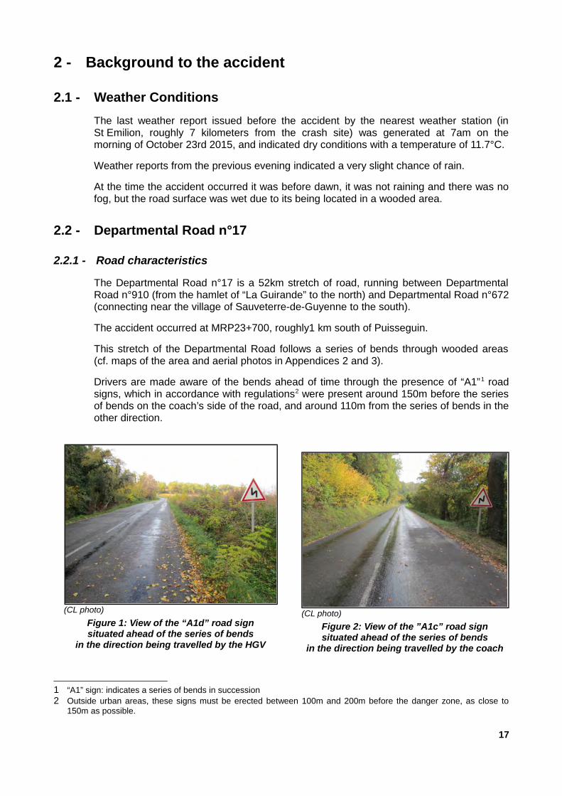
This stretch of the Departmental Road follows a series of bends through wooded areas(cf. maps of the area and aerial photos in Appendices 2 and 3).
Drivers are made aware of the bends ahead of time through the presence of “A1”1 roadsigns, which in accordance with regulations2 were present around 150m before the seriesof bends on the coach’s side of the road, and around 110m from the series of bends in theother direction.
1 “A1” sign: indicates a series of bends in succession2 Outside urban areas, these signs must be erected between 100m and 200m before the danger zone, as close to
150m as possible.
17
(CL photo)
Figure 2: View of the ”A1c” road signsituated ahead of the series of bends
in the direction being travelled by the coach
(CL photo)
Figure 1: View of the “A1d” road signsituated ahead of the series of bends
in the direction being travelled by the HGV

The lorry came off the road while travelling around a right bend in this section of the road.
The bend runs slightly uphill in the direction the articulated lorry was travelling. The bendhas an average radius of 55m. It is preceded by a slight left bend with no outer roadmarkings.
The road has an incline of between 4 and 6% towards the bend’s interior. Appendix 4 ofthis report features a plan-view diagram and a number of profile diagrams for this sectionof the road.
The road is 6m wide and has two lanes. It is covered with a surface coating and borderedby grassy banks. The outside of the bend is marked by “J1” white plastic bollardspositioned along the verge.
The two lanes are demarcated via a “T3” broken white line running along the middle of theroad, which is faded and not easily visible.
The inside of the bend is separated from the verge by “A2” kerbing3.
The bank running along the inside of the bend makes it more difficult to read the bend,while also limiting the visibility of oncoming vehicles.
This section of the road has slight ruts and the surfacing is worn in places due to theimpact of vehicle wheels.
3 “A2” kerbing: passable kerbing running along the verge.
18
(Street view photo )
Fig. 3: View of the bend where the accident occurredfrom the perspective of the lorry.

Additionally, the bend’s characteristics (road 6 metres wide, turn radius of 55m) make itparticularly difficult for heavy vehicles to navigate successfully.
2.2.2 - Road adhesion measurements
Measurements of road adhesion levels were carried out in late October 2015 on theDR 17 between Puisseguin and Saint-Genès-de-Castillon, near the site of the accidentand on both lanes of the road.
The results obtained on the lane used by the lorry involved in the accident were deemedsatisfactory, though less positive results were reported in certain places. This lack ofconsistency may be due to the presence of water or road surface contaminants (such asdead leaves) or the ruts observed in certain places.
2.2.3 - Traffic and Accident Rates
The average daily traffic for the Departmental Road number 17, according to the mostrecent data prior to the accident (from November 5th - November 13th 2014) for MRP27+600 around the area of Saint-Genès-de-Castillon, was 2,956 vehicles, of which 5.65%were heavy vehicles (these figures include traffic travelling in both directions).
There were no active traffic restrictions in the area, and the maximum speed limit was 90km/h.
Between 2010 and 2015, along the 26 km-long section of the RD 17 running betweenCoutras and Castillon-la-Bataille, 7 accidents causing bodily harm were recorded, causinga total of two deaths and seven hospitalisations.
The details and locations of these 7 accidents are included in Appendix 5 of this report.
19


3 - Summary of Investigations carried out
3.1 - Situation at the scene as encountered by emergency services
3.1.1 - Position and condition of the vehicles
The diagram and photographs in figures 4 to 7 below indicate the respective positions ofthe vehicles involved in the October 23rd accident, as they were found by emergencyservices arriving at the scene.
The coach was immobilised on the road along the verge to the right of its lane. The lorrywas immobilised in a jack-knife position along the same verge, in the opposite direction,with the front left of the vehicle resting against the front left of the coach.
21
Figure 4: Position of the vehicles upon the arrival of emergency services
(police photo)
Figure 5: Aerial view of the position of the vehicles following the collision

3.1.2 - Tyre tracks found on the road surface
Leading up to the accident, in the direction in which the lorry was travelling, judicialinvestigators found two types of tyre tracks on the road surface: one caused by tyreslipping and two tracks caused by locked wheels.
22
(police photo)
Figure 6: View (from the direction in which the articulated lorry wastravelling) of the position of the vehicles following the collision
(police photo)
Figure 7: View (from the direction in which the coach was travelling)of the position of the vehicles following the collision

23
(CL photo)
Figure 8: View of the tracks caused by tyre slippingfound on the road surface
(CL photo)
Figure 9: Close-up view of tracks found on the road surface,highlighted with red paint by judicial investigators
3.1.3 - Infrastructural Damage
The road surface and verges were badly damaged by the fire.
Several trees situated alongside the platform were also affected by the fire.
The roadside verges were stripped and cleaned, and a 170m stretch of the road wasresurfaced.
3.2 - Witness Statement Summaries
Summaries of witness statements have been compiled by technical investigators basedon the oral and written statements they examined. The summaries retain only thatinformation which has been deemed useful in understanding and analysing the events,and formulating recommendations. Disparities may exist between the various statements,or between these statements and the assessments or analyses which have beenpresented elsewhere.
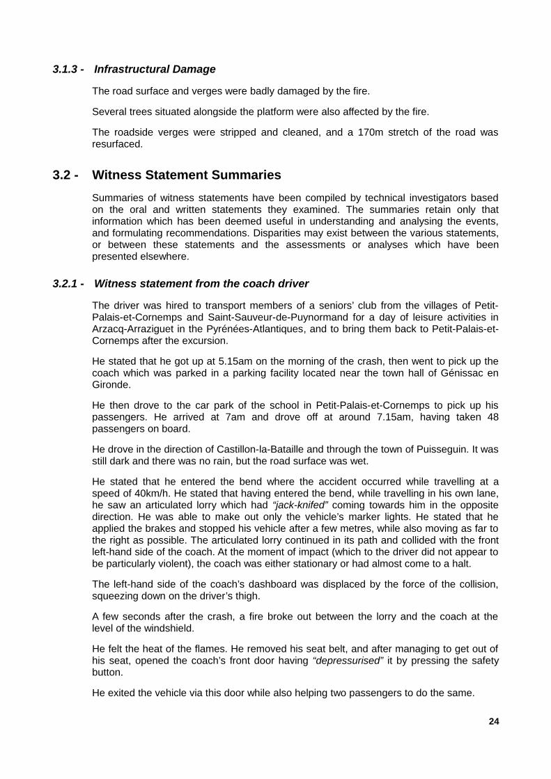
3.2.1 - Witness statement from the coach driver
The driver was hired to transport members of a seniors’ club from the villages of Petit-Palais-et-Cornemps and Saint-Sauveur-de-Puynormand for a day of leisure activities inArzacq-Arraziguet in the Pyrénées-Atlantiques, and to bring them back to Petit-Palais-et-Cornemps after the excursion.
He stated that he got up at 5.15am on the morning of the crash, then went to pick up thecoach which was parked in a parking facility located near the town hall of Génissac enGironde.
He then drove to the car park of the school in Petit-Palais-et-Cornemps to pick up hispassengers. He arrived at 7am and drove off at around 7.15am, having taken 48passengers on board.
He drove in the direction of Castillon-la-Bataille and through the town of Puisseguin. It wasstill dark and there was no rain, but the road surface was wet.
He stated that he entered the bend where the accident occurred while travelling at aspeed of 40km/h. He stated that having entered the bend, while travelling in his own lane,he saw an articulated lorry which had “jack-knifed” coming towards him in the oppositedirection. He was able to make out only the vehicle’s marker lights. He stated that heapplied the brakes and stopped his vehicle after a few metres, while also moving as far tothe right as possible. The articulated lorry continued in its path and collided with the frontleft-hand side of the coach. At the moment of impact (which to the driver did not appear tobe particularly violent), the coach was either stationary or had almost come to a halt.
The left-hand side of the coach’s dashboard was displaced by the force of the collision,squeezing down on the driver’s thigh.
A few seconds after the crash, a fire broke out between the lorry and the coach at thelevel of the windshield.
He felt the heat of the flames. He removed his seat belt, and after managing to get out ofhis seat, opened the coach’s front door having “depressurised” it by pressing the safetybutton.
He exited the vehicle via this door while also helping two passengers to do the same.
24

He then made his way to the central door of the coach, which he opened by unlocking itfrom the outside.
He helped two or three people to exit the vehicle via this central door. The safety barrierpositioned beside the stairs leading to this exit had buckled, partially blocking access tothe stairwell. Attempting to rescue the other passengers, he tried unsuccessfully to pushthe safety barrier out of the way, but was unable to enter the coach due to the thick smokeand melted plastic falling from the ceiling. It was completely dark and there were noflames, but the heat was intense.
He returned to the front right-hand side door. He rescued a person who was lying underthe dashboard, conscious but unable to move. He slid her down the stairs and laid her onthe ground away from the bus.
The coach rapidly became engulfed in flames, making it impossible to access thevehicle’s interior.
He then looked after the passengers who were able to evacuate the coach, and with thehelp of a passing motorist gathered them together on the roadside behind the vehicle.
He did not approach the vehicle again, as he was worried it might explode. A few minuteslater he heard a series of small explosions, most likely the vehicle’s windows, pneumaticsystems and air pipes.
The emergency services then arrived, with the first teams arriving from Castillon.
3.2.2 - Witness statements from coach passengers
Statements were also taken from the seven passengers who were able to escape thevehicle. For ease of readability, these seven passengers are referred to as “P1” - “P7”.
Witness statement from passenger “P1”
This passenger stated that she was sitting in the window seat of the right-hand row, justbehind the coach’s central door. In front of her there was a safety barrier separating herseat from the stairs.
At the moment of impact, all the overhead lights in the coach went off, leaving all thepassengers in complete darkness. Not having fastened her seat belt, she was thrownforward by the force of the impact. The barrier in front of her had broken, and so shefound herself on the stairs.
Flames immediately began to appear at the front and on the right-hand side of the coach.
She saw a passenger from the row of seats to her left attempting to break the sidewindow, before another passenger opened the central door on the right-hand side of thecoach and helped her out.
Outside she saw the coach driver and a woman. She saw two other people exiting thecoach, one of whom was a “badly burned” woman who was pulled out by the coach driverand a passing motorist.
The passenger who had attempted to break the window joined them shortly afterward.
25

Witness statement from passenger “P2”
This passenger stated that he was seated towards the middle of the coach, by the windowon the driver’s side. He had not fastened his seat belt.
He was reading a book when the accident occurred. Having felt the impact, he raised hishead and immediately saw the fire breaking out on the lorry and the front of the coach.The flames were red in colour, glowing.
He immediately jumped up and grabbed the window hammer, which was located betweenhis window and the one in front. He told the passenger seated to his right to follow him,shouted “open the doors”, smashed the window of the coach’s central door and exitedthrough this opening, falling onto the roadside. The smoke had reached him before he leftthe coach, ahead of the flames. It was black, thick and acrid, giving off an odour ofburning plastic.
He lost consciousness for a few moments; when he came to, the coach was completelyablaze. Outside the coach he saw the driver and two other passengers.
Witness statement from passenger “P3”
This passenger stated they were seated in the aisle seat on the driver’s side of thevehicle’s 4th row (passenger “P4” also claimed to have been sitting in this seat). She hadfastened her seat belt.
When the accident occurred, she felt the impact and heard a loud noise. The front of thecoach caught fire immediately. White and black smoke began moving towards the back ofthe coach.
After unfastening her seat belt, she got up and followed the aisle to reach the vehicle’scentral door on the right-hand side.
She fell down the stairs with another woman and found herself outside with her.
She then took shelter. The two women were met by a motorist who put them in his caruntil the emergency services arrived.
Witness statement from passenger “P4”
This passenger stated that she was seated in the aisle seat of the vehicle’s 4 th row, on thedriver’s side.
She did not see the collision occur but was taken aback by the noise and force of theimpact. She immediately saw flames rising at the front and then on the left-hand side ofthe coach where she was seated.
She got up and made her way to the central door on the vehicle’s right-hand side.
The door was open by the time she reached it. She was grasped by someone who pulledher outside the vehicle, and she found herself on the roadside.
This witness described how quickly the fire developed, with explosions, an intense heatand materials from the ceiling which were melting and dripping on to her.
26

Witness statement from passenger “P5”
This passenger stated that he was seated on the right hand side of the vehicle besidepassenger “P6”, in the 3rd row in front of the central door. He had fastened his seat belt.
After the impact, he saw the flames, unfastened his seat belt and passenger P6’s seatbelt, and exited the vehicle via the open central door. He came back to the vehicle withanother man, and with his help pulled two unconscious people out of the vehicle, whowere lying in the stairs leading down to the door.
This passenger described an immediate conflagration and the presence of black smoke.
Witness statement from passenger “P6”
This passenger stated that she was seated towards the back of the vehicle, 3 or 4 rowsbehind the central door on the vehicle’s right-hand side, in the aisle seat besidepassenger “P5” (according to passenger P5’s statement, these seats where located 3rows in front of the central door). She had fastened her seat belt.
At the moment of impact, her head was thrown against the seat in front of her, breakingher glasses. Passenger P5 unfastened her seat belt and brought her towards the centraldoor. As she exited the vehicle, someone pulled her outside.
Witness statement from passenger “P7”
This passenger stated that she was seated in the aisle seat of the first row on the right-hand side. She had fastened her seat belt.
The tour leader was seated in front of her on the small chair beside the door and theconductor.
When the coach entered the bend, she saw the headlights of an oncoming vehicle. Shesaw the lorry coming towards the left-hand side of the coach. The impact happened veryquickly.
After the impact, she saw the coach driver “fiercely kicking” the door in order to open it.
She was pulled out of the coach by a person she later identified as the coach driver. Shelay on her back on the ground while waiting for the emergency services.
3.2.3 - Witness statements from motorists present at the scene of the accident
Witness statements were also taken from motorists who happened upon the scene of theaccident.
These witnesses arrived on the scene after the collision, when the two vehicles hadalready caught fire. None of these motorists were in any way involved in the crashbetween the lorry and the coach.
The witnesses described a raging fire and several explosions, which quickly preventedthem from approaching the vehicles to try and rescue the passengers still inside thecoach.
27

3.3 - The coach
3.3.1 - Organisation of the excursion
On October 23rd 2015, the seniors’ clubs from the villages of Petit-Palais-et-Cornemps andSaint-Sauveur-de-Puynormand, both situated in the Gironde department (33), hadorganised an excursion to attend the “garbure” festival at Arzacq-Arraziguet in thePyrénées-Atlantiques (66).
A tour leader and 47 people, mostly retirees from the villages of Petit-Palais-et-Cornempsand Saint-Sauveur-de-Puynormand, were participating in the excursion.
Transport for both legs of the journey between Petit-Palais and Arzacq-Arraziguet wasprovided by a local transport company.
The meeting point was the car park of the local school in Petit-Palais-et-Cornemps, withthe departure time set for 7.15 am.
The coach set off on the road to Arzacq-Arraziguet (64) at around 7:15am.
3.3.2 - The coach driver
3.3.2.1 - Experience and employment
The coach driver was a 39-year-old man having held a category D licence to drive publictransport vehicles since 1997. This licence was valid at the time the accident occurred.
The documents examined by the technical investigators did not reveal any failure to meetadministrative requirements.
He had been employed by the transport company as a driver since April 2015.
3.3.2.2 - Activity prior to the accident
On Monday 19th and Tuesday 20th of October, the driver was off work. On WednesdayOctober 21st, he completed a journey towards Bordeaux.
On the day before the accident, Thursday October 22nd, he was also off work.
On Friday October 23rd, he got up at around 5.15am. He drove his personal vehicle to acar park located beside the Génissac town hall to pick up the coach, which was parkedthere.
At around 6.15am he left the car park driving the coach in order to make his way to Petit-Palais-et-Cornemps and pick up his passengers.
At around 7am, he arrived at the meeting point in Petit-Palais-et-Cornemps.
At around 7.15 am, having taken on board the 48 passengers, he set off on the road toArzacq-Arraziguet (64).
The accident occurred at around 7.30, after roughly 15 minutes of journey time.
28

3.3.2.3 - Drug and alcohol testing
The driver was subjected to testing for drug and alcohol consumption, both of which werenegative.
3.3.3 - Technical characteristics of the coach
The coach involved in the accident was a Mercedes Benz type R2 457H bearing the tradename Tourismo RHD, belonging to a rental company which rented the vehicle to thetransport company.
Its curb weight was 13.9 tonnes and its GVWR4 was 19 tonnes.
The vehicle had 55 seats, all of which were fitted with seat belts.
Brought into operation in January 2011, the coach was in good overall condition at thetime of the accident. It had passed a technical inspection on August 31st 2015, validatingthe vehicle’s roadworthiness until February 29th 2016. The vehicle was compliant withactive regulations in France.
Investigators were unable to determine the vehicle’s mileage.
Its motor was positioned lengthways towards the rear of the vehicle. The coach ran ondiesel fuel.
The coach was equipped with both heating and air conditioning systems.
4 Gross Vehicle Weight Rating
29
Figure 10: Journey taken by the coach on October 23rd

The following paragraphs describe the equipment, materials and systems in place onboard the coach which may have played a role in the development of the fire, as well asthe vehicle’s safety features.
3.3.3.1 - Description and position of fuel tanks
The coach was fitted with two polyethylene fuel tanks positioned in front of the front axle,roughly 1.5m behind the front end of the superstructure:
➢ The right fuel tank had a capacity of 235 litres;
➢ the left fuel tank had a capacity of 264 litres.
(EV document annotated by the BEA-TT)
Figure 12: Position of coach’s fuel tanks
(EV document annotated by the BEA-TT)
Figure 13: Diagram of coach’s fuel tanks
30
(police photo)
Figure 11: View of the coach before the accident
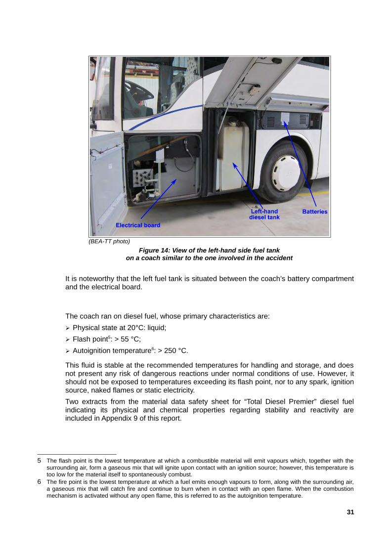
It is noteworthy that the left fuel tank is situated between the coach’s battery compartmentand the electrical board.
The coach ran on diesel fuel, whose primary characteristics are:
➢ Physical state at 20°C: liquid;
➢ Flash point5: > 55 °C;
➢ Autoignition temperature6: > 250 °C.
This fluid is stable at the recommended temperatures for handling and storage, and doesnot present any risk of dangerous reactions under normal conditions of use. However, itshould not be exposed to temperatures exceeding its flash point, nor to any spark, ignitionsource, naked flames or static electricity.
Two extracts from the material data safety sheet for “Total Diesel Premier” diesel fuelindicating its physical and chemical properties regarding stability and reactivity areincluded in Appendix 9 of this report.
5 The flash point is the lowest temperature at which a combustible material will emit vapours which, together with thesurrounding air, form a gaseous mix that will ignite upon contact with an ignition source; however, this temperature istoo low for the material itself to spontaneously combust.
6 The fire point is the lowest temperature at which a fuel emits enough vapours to form, along with the surrounding air,a gaseous mix that will catch fire and continue to burn when in contact with an open flame. When the combustionmechanism is activated without any open flame, this is referred to as the autoignition temperature.
31
(BEA-TT photo)
Figure 14: View of the left-hand side fuel tankon a coach similar to the one involved in the accident

3.3.3.2 - Description of heating and air conditioning systems
The vehicle’s heating and air conditioning systems run on two separate circuits, eachusing fluids with differing characteristics. However, our analysis of these systems (cfAppendix 6) indicates that they share the use of certain technical components, at whichpoints their systems converge. This is the case in particular for the frontal control unit.
(BEA-TT photo) (BEA-TT photo)
Figure 15: View of the frontal heating and airconditioning control unit on a similar coach
Figure 16: View of the connectors linkingthe frontal control unit to the heating
and air conditioning systemson a similar coach
3.3.3.3 - Description of the frontal heating and air conditioning control unit
The exchange unit installed at the front of the coach has a dual purpose: providing heatingfor the front of the coach and the driver’s seat, and providing air conditioning.
Inside this control unit there are two heat exchangers:
➢ a radiator connected to the coach’s heating system, circulating Glysantin G38-type heattransfer fluid
➢ an evaporator connected to the coach’s air conditioning system, circulating R134acoolant.
Figures 17 and 18 provide a schematic view of the position of the heating radiator and theair conditioning evaporator in the control unit, and their connection to the heating and airconditioning circuits.
32

The coolant fluid used in the coach's air conditioning system is R134a.
Stable at ambient temperatures and under normal conditions of use, its primarycharacteristics are as follows:
➢ Physical state at 20 °C: gaseous;
➢ Melting point7: -101 °C;
➢ Boiling point8: -26.4 °C ;
➢ Flash point9: > 55 °C;
➢ Autoignition temperature10: 743 °C.
7 The melting point is the temperature at which, at a given level of pressure, a material will melt, i.e.: pass from a solidstate to a liquid state.
8 The boiling point is the temperature at which, at a given level of pressure, a substance will pass quickly from a liquidto a gaseous state.
9 cf. note 510 cf. note 6
33
(EV document annotated by the BEA-TT)
Figure 17: Diagram of frontal heating and air conditioningcontrol unit
(EV document annotated by the BEA-TT)
Figure 18: Cross-section of the frontal heatingand air conditioning control unit

The heat transfer fluid used in the coach’s heating system is Glysantin G48. This fluid isstable under normal conditions of use, and its primary characteristics are as follows:
➢ Physical state: liquid;
➢ Boiling point >= 165 °C;
➢ Flash point: > 126.5 °C;
➢ Autoignition temperature: > 440 °C.
An extract from the material data safety sheet for these fluids, indicating their physical andchemical properties and primary characteristics regarding reactivity and stability, areincluded in Appendices 7 and 8 of this report.
Another component in which the heating and cooling circuits converge is the unit installedon the roof of the vehicle, which includes (among other elements) fans.
3.3.3.4 - Description of evacuation measures: doors, lighting and emergency exits
Doors
The coach was equipped with two doors allowing passengers to board and alight thevehicle. Both were situated on the vehicle’s right-hand side, one at the front and one in themiddle.
34
(BEA-TT photo)
Figure 19: View of the air treatment unit on the roof of a similar coach

Boarding and alighting the vehicle via either door was achieved via a flight of steps,allowing only one person to pass at a time.
The stairs at the front of the bus included a small landing near the driver’s seat.
The central stairs were particularly steep and narrow, and were bordered by the coach’stoilets on one side and a safety barrier on the other.
(BEA-TT photo)
Figure 21: View of the central door from outside the coach
(BEA-TT photo)
Figure 22: View of the front entrancefrom outside the coach
35
(EV document annotated by the BEA-TT)
Figure 20: Position of coach door

Opening and closing the doors
The two doors were opened and closed via the use of a pneumatic mechanism operatedfrom the driver’s seat, or from the doors themselves.
The doors could also be opened by using the security handles located beside each dooron both the inside and outside of the coach. Pulling the emergency handle causes thepressure to drop in the door’s pneumatic circuit, allowing the door to be opened manually.
In the event that the pneumatic system controlling the doors is compromised (e.g. during acollision) the pressure will automatically drop after 8 seconds and the doors can then beopened manually.
Lighting and emergency exits
The coach was not equipped with any emergency lighting measures.
The emergency exits were located on the roof and sides of the vehicle.
On the roof, the vehicle was equipped with two passenger evacuation panels, which alsoacted as smoke evacuators. The use of these emergency exits is recommended when thecoach is lying on its right-hand side, rendering its doors unusable. The emergency roofexits are opened via ejection or by breaking with an emergency hammer (located near theexit).
The sides of the coach are equipped with five windows acting as emergency exits; two onthe right and two on the left. The words “Issue de secours” (“Emergency Exit”) weredisplayed on these windows, each of which also had an emergency hammer located justbeside it. In order to use these emergency exits, they must first be broken using anemergency hammer.
The diagram and photographs in figures 25 - 27 below show the position of emergencyexits and emergency hammers for a coach similar to the one involved in the accident.
36
(BEA-TT photo)
Figure 23: View of the central doorfrom the inside of the coach
(BEA-TT photo)
Figure 24: Alternative viewof the central door from inside the coach

(BEA-TT photo)
Figure 26: View of an emergency hammerfor a side window on a coach
similar to the one involved in the accident
(BEA-TT photo)
Figure 27: View of an emergency exiton the roof of a coach
similar to the one involved in the accident
37
(EV document annotated by the BEA-TT)
Figure 25: Position of emergency exits and emergency hammers on the coach

In light of their examination, BEA-TT investigators made the following observations:
➢ the central exit was accessed via a steep and narrow staircase, whose steps wheremuch higher than those found at the front door, making the stairs more difficult to climbor descend;
➢ in the absence of emergency lighting and smoke extractors, emergency exits andmaterials are not visible at night or when the vehicle cabin is filled with smoke.
3.3.3.5 - Description of materials used in the coach’s interior and their fire resistantproperties
The ceiling covers, baggage rails and door/window frames were mostly made usingABS11, polypropylene and polyurethane.
The sides of the coach were made up of insulating wood fiber panels.
The seat covers, curtains and interior decor materials were made of fabrics containingpolyester, wool and viscose.
The seat stuffing was made from polyurethane.
The flooring was made from wood with a PVC floor covering, while the carpet for the aislewas made mostly from polyamide and polyester fibres.
These materials were in compliance with ECE/ON regulation n°188 regarding uniformtechnical requirements concerning the burning behaviour of materials used in theconstruction of certain categories of motor vehicles, as well as European Directive 95/28regarding the burning behaviour of materials used in the interior construction of certaincategories of motor vehicle.
The melting point varies for each material used (between 220°C and 250°C for ABS, andaround 190°C for polyurethane). As a general rule, the materials used, although compliantwith existing regulations, were flammable above a certain temperature.
The gases released by combustion of these materials are known on a theoretical basisonly,12 and are not subject to testing under legislation.
3.3.4 - Expert assessment of the coach
3.3.4.1 - Condition of the vehicle prior to the accident
The coach had been issued with a certificate of compliance. It was in good condition andno modifications or anomalies were observed which could have influenced the vehicle’srange of motion before the collision, its response to the impact or its response to theoutbreak of a fire.
3.3.4.2 - Damage to the coach
The coach was completely destroyed by the fire that broke out following the collision. Allflammable materials were consumed, leaving only a small amount of unusable residuebehind.
The vehicle’s metallic structure and lining panels were deformed by the heat of the fire.
11 ABS or acrylonitrile butadiene styrene is a thermoplastic polymer often used in automobile construction.12 The gases released by the combustion of these materials consisted mainly of CO (carbon monoxide), CO2 (carbon
dioxide), HCN (hydrogen cyanide), NH3 (ammonia), and HCL (hydrogen chloride), all of which are highly toxic.
38

The vehicle suffered a frontal collision with the lorry on its left-hand side, causing its solidstructures to be pushed back. The deformations to the vehicle's structure were mostlyconcentrated in the areas indicated in figures 28 - 31 below.
The vertical structure on the coach’s front left-hand side had been crushed inwards byaround 80cm.
The coach driver’s seat was pushed backwards to a significant degree from the front left-hand side.
The electrical board situated on the front left-hand side of the coach, as well as thestructure protecting the left fuel tank were heavily deformed by the impact with the tractorunit. The space between the exterior stanchions for the fuel tank compartment wasreduced by around 65%.
The BEA-TT investigators have surmised that the left-hand side fuel tank located withinthe impact zone was most likely also crushed, which may have led to its rupture during thecollision.
39
(police photo.)
Figure 29: Wider view of coach
(EV document annotated by the BEA-TT)
Figure 28: Position of areas of structural damage to the coach

40
(police photo.)
Figure 30: View of the front left-hand side of the coachinvolved in the accident
(police photo.)
Figure 31: Close-up view of the front left-hand sideof the coach involved in the accident
(police photo.)
Figure 32: Close-up view of the front left-hand sideof a coach similar to the one involved in the accident

The battery compartment situated above the left front wheel does not show any majordeformation. The battery elements are correctly assembled and the terminals are still inplace, allowing us to exclude the possibility of an internal explosion.
The central and right-hand side portions of the coach’s front do not show any signs ofdirect impact with the lorry.
The coach’s frontal heating and air conditioning control unit was partially destroyed in thefire. The radiator and evaporator installed in this control unit were not destroyed by thefire, and were lying on the ground. They showed no visible signs of being crushed.
In light of these observations, the BEA-TT investigators have ruled out the hypothesis thata direct impact with the frontal heating and air conditioning control unit was what led to thesudden rupture of the heating and air conditioning circuits. Their role in causing the twovehicles to be consumed by fire can therefore be dismissed.
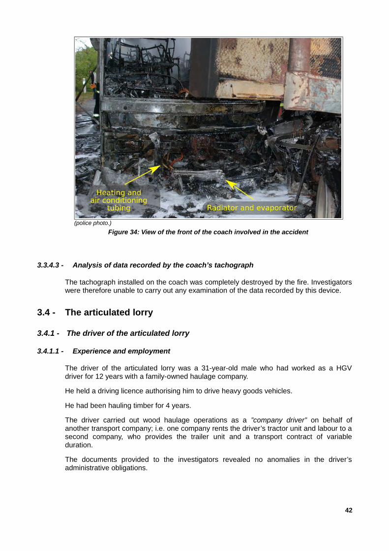
Figure 34 below provides a view of the front of the coach, the radiator and the evaporatoras well as the tubing to which they were attached as they were found by the judicialinvestigators once the blaze had been quelled by the firefighters.
41
(EV document annotated by the BEA-TT)
Figure 33: Position of the heatingand air conditioning control unit
and areas of structural damage on the front of the coach
3.3.4.3 - Analysis of data recorded by the coach’s tachograph
The tachograph installed on the coach was completely destroyed by the fire. Investigatorswere therefore unable to carry out any examination of the data recorded by this device.
3.4 - The articulated lorry
3.4.1 - The driver of the articulated lorry
3.4.1.1 - Experience and employment
The driver of the articulated lorry was a 31-year-old male who had worked as a HGVdriver for 12 years with a family-owned haulage company.
He held a driving licence authorising him to drive heavy goods vehicles.
He had been hauling timber for 4 years.
The driver carried out wood haulage operations as a ”company driver” on behalf ofanother transport company; i.e. one company rents the driver’s tractor unit and labour to asecond company, who provides the trailer unit and a transport contract of variableduration.
The documents provided to the investigators revealed no anomalies in the driver’sadministrative obligations.
42
(police photo.)
Figure 34: View of the front of the coach involved in the accident

3.4.1.2 - Activity prior to the accident
The driver of the articulated lorry was off work on Saturday October 17th and SundayOctober 18th, spending the weekend at his home in Orne (61).
He went back to work on Monday October 19th, bringing his 3-year-old son with him.
He made his way to the depot of a company based in Mayenne (53) to pick up hisarticulated lorry (which had been left there over the weekend), and drove off to begin aweek’s work along with his son.
After various wood haulage operations completed at the beginning of the week inNormandy, Pays de Loire, Poitou-Charentes and Aquitaine, on the morning of ThursdayOctober 22nd he made his way to Champrond-en-Gatine in Eure-et-Loire (28) to take on aconsignment of logs, to be delivered to Saint-Michel-de-Montaigne in Dordogne (24) onthe following morning. Upon delivery, he was to travel to Loches en Indre-et-Loire (37) totake on a final load and return to the company depot.
On the evening of Thursday October 22nd, he stopped for the night in the car park of arestaurant in Coutras, Gironde (33). He slept in the cabin of his tractor unit with his son.
He left Coutras on Friday October 23rd 2015 at around 5.30am and made his way to thepremises of a company based in Saint-Michel-de-Montaigne, Dordogne (24) to deliver hiscargo of wood.
He arrived in Saint-Michel-de-Montaigne at around 6am and left at around 7am, havingunloaded his cargo.
The accident occurred at around 7.30am, after roughly 20-30 minutes of journey time.
43
Figure 35: Journey taken by the articulated lorry on October 23rd

3.4.1.3 - Drug and alcohol testing
Tests for drug and alcohol consumption (carried out post mortem) came back negative.
3.4.2 - Technical characteristics of the tractor unit
The articulated lorry consisted of an IVECO tractor unit and a BILLAUD semitrailer.
The tractor unit was an IVECO model AS40 S56 TZP HM (category N313), belonging to arental society located in Sarthe (72), which rented the unit to the transport company.
It was equipped with a diesel-fuelled engine.
The vehicle was registered in September 2014.
It had undergone a technical inspection on August 24th 2015, validating the vehicle’sroadworthiness until August 24th 2016.
Investigators were unable to determine the vehicle’s mileage.
The vehicle’s primary technical characteristics were as follows:
➢ GVWR of 26 tonnes;
➢ GCVWR of 60 tonnes.
The tractor unit was equipped with an Electronically Controlled Brake System (EBS),which included the following four functions:
➢ ABS (Anti-lock Braking System): a system preventing the wheels from locking whenbraking;
➢ BAS (Brake Assistant System): a system to amplify braking power in emergencies;
13 The vehicle was designed and built to transport freight with a maximum weight of over 12 tonnes.
44
(police photo.)
Figure 36: View of the IVECO tractor unit involved in the accident

➢ EBL (Electronic Brakeforce Limitation): a system that optimises braking power based onload weight;
➢ ASR (Anti-Slip Regulation): system preventing the drive wheels from slipping duringacceleration;
➢ However, the tractor unit was not equipped with ESB or AEBS systems:
➢ ESB (Electronic Stability Program): system designed to control the vehicle’s lateralmovement, particularly in order to improve stability in coupled vehicles duringundersteer and oversteer;
➢ AEBS (Advanced Emergency Braking System): a system which automatically activatesthe vehicle’s braking systems in order to avoid a collision or reduce the speed of impact.
The following paragraphs describe the equipment, materials and systems installed on thetractor unit which may have played a role in causing or spreading the fire.
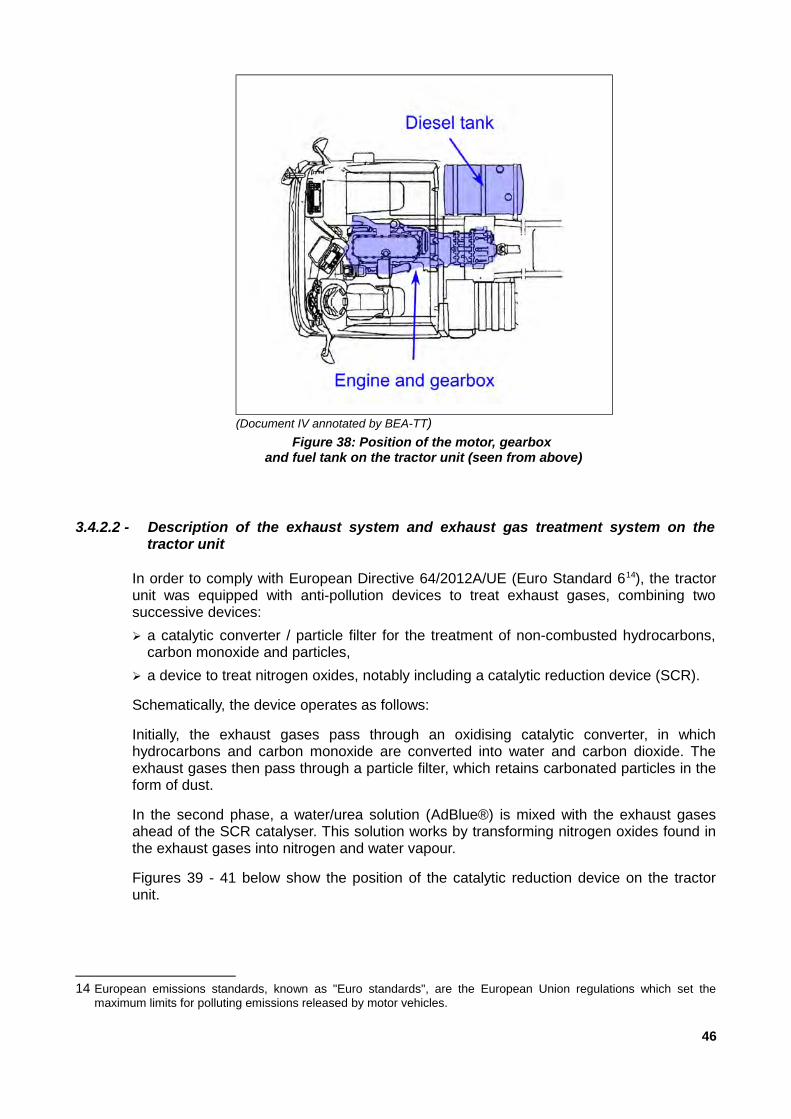
3.4.2.1 - Position of the fuel tank and main mechanical components of the tractor unit
The tractor unit was fitted by its manufacturer (IVECO) with a 540-litre aluminium fueltank, mounted lengthwise on the right-hand side of the tractor unit. Its dimensions were asfollows: 1.44m in length, 0.64m in height and 0.69m in width.
The main mechanical components on the tractor unit containing fluids that might haveescaped and caught fire during the collision are mostly located in the centre of the vehicleunderneath the cabin.
Figure n°38 shows their position on the tractor unit.
45
(police photo.)
Figure 37: View of a similar primary fuel tankto the one fitted on the IVECO tractor unit involved in the accident
3.4.2.2 - Description of the exhaust system and exhaust gas treatment system on thetractor unit
In order to comply with European Directive 64/2012A/UE (Euro Standard 614), the tractorunit was equipped with anti-pollution devices to treat exhaust gases, combining twosuccessive devices:
➢ a catalytic converter / particle filter for the treatment of non-combusted hydrocarbons,carbon monoxide and particles,
➢ a device to treat nitrogen oxides, notably including a catalytic reduction device (SCR).
Schematically, the device operates as follows:
Initially, the exhaust gases pass through an oxidising catalytic converter, in whichhydrocarbons and carbon monoxide are converted into water and carbon dioxide. Theexhaust gases then pass through a particle filter, which retains carbonated particles in theform of dust.
In the second phase, a water/urea solution (AdBlue®) is mixed with the exhaust gasesahead of the SCR catalyser. This solution works by transforming nitrogen oxides found inthe exhaust gases into nitrogen and water vapour.
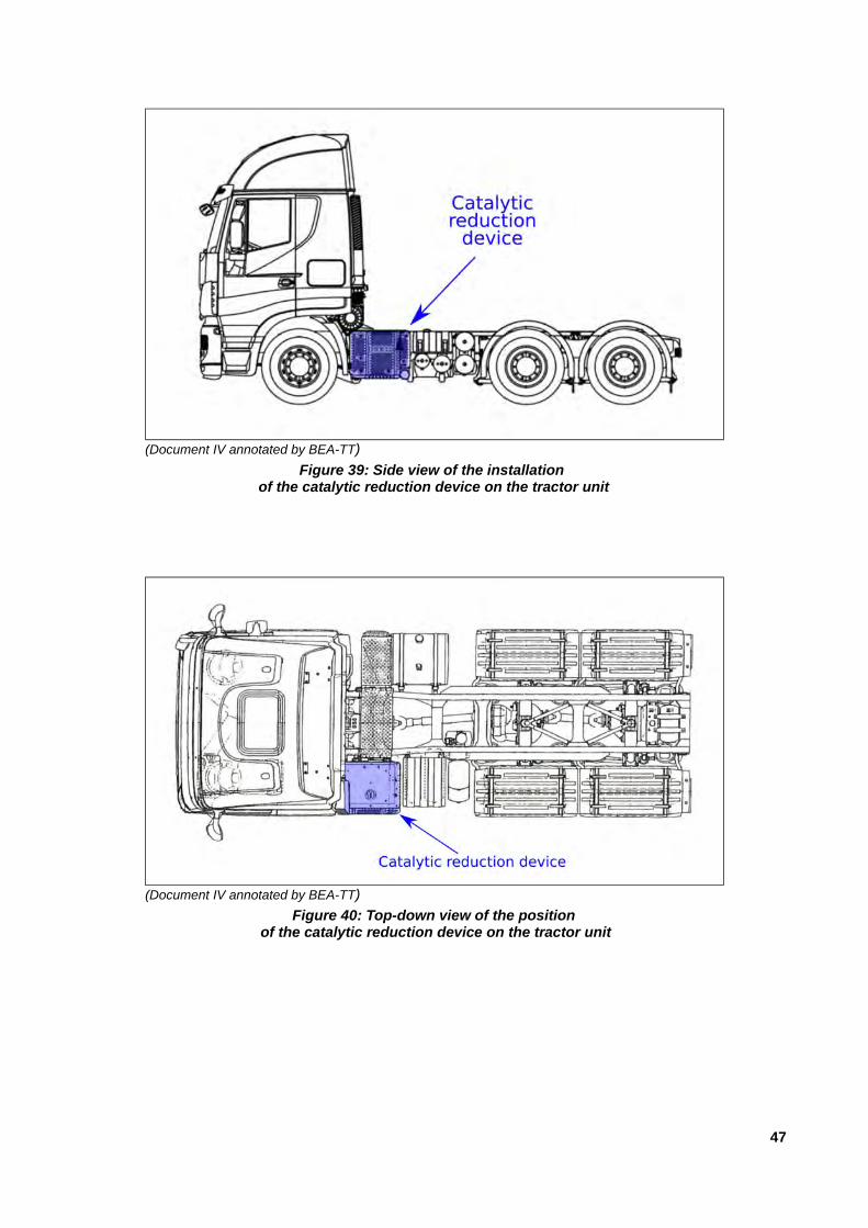
Figures 39 - 41 below show the position of the catalytic reduction device on the tractorunit.
14 European emissions standards, known as "Euro standards", are the European Union regulations which set themaximum limits for polluting emissions released by motor vehicles.
46
(Document IV annotated by BEA-TT)
Figure 38: Position of the motor, gearbox and fuel tank on the tractor unit (seen from above)
47
(Document IV annotated by BEA-TT)
Figure 39: Side view of the installation of the catalytic reduction device on the tractor unit
(Document IV annotated by BEA-TT)
Figure 40: Top-down view of the position of the catalytic reduction device on the tractor unit

These reactions occur at high temperatures, with exhaust gases capable of reachingtemperatures of 500-600 °C as they exit the motor. Figure 42 below, submitted by thetractor unit manufacturer (IVECO), shows the temperatures reached by the metallic sheetprotecting the catalytic reduction device during measurements taken immediately after themotor had been shut off after 50 minutes of activity - temperatures rising to as high as200°C. The components of the catalytic reduction device, protected by this metalcovering, reach even higher temperatures.
48
(police photo.)
Figure 41: View of the catalytic reduction deviceon the tractor unit
(document IV)
Figure 42: Temperatures measured on the outer surfaceof the catalytic reduction device after shutting off the vehicle’s motor

3.4.2.3 - Description of the tractor unit’s air conditioning system
The cabin of the tractor unit was equipped with an air conditioning system. The coolantused in this air conditioning system is R134a, which is non-flammable (cf. Appendix 7).Figures n° 43 and 44 below show the position of this system on the tractor unit.
3.4.3 - Modifications made to the tractor unit following its factory release
The expert assessment of the vehicle showed that following its factory release, thefollowing modifications had been made to the tractor unit:
➢ addition of headlights and other lights;
➢ addition of two tanks behind the cab: one fuel tank and a tank containing an aqueousurea solution (commercial name AdBlue®);
➢ fifth-wheel coupling moved further towards the rear of the vehicle.
3.4.3.1 - Addition of headlights and other lights
The tractor unit was equipped with various vehicle lights and decorative lights in additionto its approved factory configuration. In particular, the investigation showed that thefollowing had been installed:
➢ a row of six lights above the cabin;
➢ four decorative lights around the sun-visor in the upper cabin,
➢ four lights below the radiator grill;
➢ a dozen decorative lights on the bumper and radiator grill.
Figures 45 and 46 below show the lights installed on the tractor unit and the expected lightoutput when they were switched on.
49
(Document IV annotated by BEA-TT)
Figure 43: Position of the air conditioning controlunit in the tractor unit’s cabin (perspective view)
(Document IV annotated by BEA-TT)
Figure 44: Layout of the highway tractor’s airconditioning unit in the cab (top-down view)

Current regulations limit the number of dipped beams to two (Article R. 313-3 of theFrench Highway Code) and the number of full beams to four (article R. 313-2 of theFrench Highway Code). The investigations carried out did not allow us to ascertainwhether or not the tractor unit complied with these rules.
Elsewhere, current regulations prohibit luminous decorations on vehicle exteriors (ArticleR. 313-1 of the FrenchHighway Code).
The lights installed on the tractor unit were therefore not compliant with existingregulations, but nor did they have any influence on the cause or consequences of theaccident.
50
(police photo.)
Figure 45: View of the headlights and decorative lightson the tractor unit
(police photo.)
Figure 46: View of the tractor unit using dipped headlights with the decorative lights switched on.

3.4.3.2 - Addition of an extra fuel tank
The tractor unit was equipped with an additional fuel tank with a capacity of 375 litres,increasing the vehicle’s overall fuel capacity by 70%. This tank was made by a companycalled AFHYMAT, based in Roye, Somme (80), and was installed on the tractor unit inSeptember 2014 by a garage in Orne (61).
The tank was fitted crosswise on the chassis of the tractor unit, behind the driver’s cab. Itsdimensions were as follows: 2.08 m in length, 0.65m in height and 0.32m in width. Thetank was made from 3mm-thick 5754 H111 aluminium.
It was mounted on an independently-constructed support structure, using metal strapssupplied by AFHYMAT. It was fitted with a vented fuel cap, an anti-siphoning device and adevice to limit excess pressure in the tank to 0.2 bar. It was connected to the main fueltank via metal tubing fitted with a solenoid valve.
The diagrams in figures 47 - 52 show the additional fuel tank on the tractor unit, as well asits exact poition and layout.
51
(Document IV annotated by BEA-TT)
Figure 47: Position of the additional fuel tankto the rear of the cabin (side view)
(Document IV annotated by BEA-TT)
Figure 48: Position of the additional fuel tankto the rear of the cabin (top-down view)

3.4.3.3 - Legal status of the additional fuel tank
The installation of an additional fuel tank is not considered a “major transformation” asindicated in Article R. 321-16 of the French Highway Code, and defined in Article 13 of thegovernment decree issued on July 19th 1954 pertaining to the registration of motorvehicles. As such, vehicles modified in this way do not require a new registration in orderto remain compliant with applicable regulations.
However, it is up to the installer (the person providing the vehicle modification service) toensure that the modified vehicle remains compliant with regulations. This proof ofcompliance may take the form of a statement by the vehicle manufacturer indicating thatthe modification having been carried out is approved, or a testing report issued by arecognised vehicle testing laboratory.
When a vehicle manufacturer plans for the installation of such a component, either asstandard or as an optional extra, they will approve the different variants for use with thevehicle. In this case, the manufacturer would chose an approved fuel tank as a separatetechnical component and approve its installation in accordance with existing Europeanregulations.
52
(document AF)
Figure 49: Plan view of the additional fuel tank
(document AF)
Figure 50: Perspective view of the additional fuel tank
(police photo.)
Figure 51: View of the fuel tanks installedon the IVECO tractor unit involved in the accident
(police photo.)
Figure 52: View of the additional fuel tankon the IVECO tractor unitinvolved in the accident

This was not the case for the tractor unit involved in the accident, as its manufacturer(IVECO) had not approved the option of adding an additional fuel tank to the vehicle.
The additional fuel tank installed on the tractor unit was provided by a company namedAFHYMAT. This company was unable to provide BEA-TT investigators withdocumentation indicating the tank’s approval as a separate technical component, as theapproval request was still being processed at the time of the BEA-TT’s request. However,it should be noted that the model provided belongs to an approved product line of fueltanks (TUTAC Report n° 02/07974 issued on November 22nd 2002), and that for the tankto be approved all that was required was an extension of the existing approval report.
In addition, none of the documents examined by the BEA-TT gave any indication of anapproval request having been submitted for the installation of the fuel tank on thisparticular tractor unit.
In conclusion, neither the fuel tank nor its installation on the back of the tractor unit’s cabinwere officially approved at the time the accident occurred.
3.4.3.4 - Addition of an extra AdBlue® tank
An additional aluminium-alloy storage tank with a capacity of 72 litres was installed on thevehicle chassis behind the cabin (between the cabin and the additional fuel tank). It waspositioned on the right-hand side of the tractor unit, above the original AdBlue® tank.
It is made up of two compartments. Its dimensions were as follows: Length: 70 cm /Height: 42 cm / Width: 32cm
AdBlue® is an aqueous solution consisting of 32.65% urea and 67.5% demineralisedwater, and is non-flammable.
The documents examined by BEA-TT investigators did not give any information regardingthe installation of this tank on the tractor unit.
53
(BEA-TT photo)
Figure 53: View of the additionalAdBlue® tank

3.4.3.5 - Rearward repositioning of the fifth-wheel coupling
Accounting for the addition of extra tanks behind the cab and the articulation angle of thetrailer15, the fifth-wheel coupling of the tractor unit was moved back towards the rear of theof the vehicle, in order to leave sufficient space for the trailer’s pneumatic and electricalconnectors.
The original position of the fifth-wheel coupling was determined by the judicial expert incharge of vehicle assessments, with the aid of the tractor unit’s technical design plansprovided by its manufacturer (IVECO). The position of the fifth-wheel coupling on thewreck of the tractor unit allowed the investigator to estimate it had been moved backwardby around 18cm.
Figures 54 and 55 below (taken from the judicial expert’s report) show the original positionof the fifth-wheel coupling and that measured during the post-crash analysis.
15 The articulation angle of the trailer equates to the distance between the coupling pivot and the front corners of thetrailer.
54
(document FB annotated by BEA-TT)
Figure 54: View of the fifth-wheel couplingpositioned in accordance with the distance measured

The judicial investigator observed that the modification to the position of the fifth-wheelcoupling was not carried out in compliance with the manufacturer’s directives, and thatthis modification was therefore not compliant with applicable regulations.
Furthermore, taking into account this modification and the respective dimensions of thetractor unit and the trailer, the overall length of the articulated lorry was increased to16.565m
The articulated lorry therefore did not comply with the stipulations of Article R. 312-11 ofthe French Highway code, which states that the length of an articulated vehicle, measuredto include movable superstructures and standard freight items such as containers andmobile crates, as well as anything projecting lengthwise from the vehicle, must notexclude 16.5m - otherwise, the vehicle is subject to regulations for exceptional transportvehicles.
However, the judicial expert concluded that the modifications described above, i.e. theaddition of extra fuel and AdBlue® tanks and the repositioning of the fifth-wheel coupling,did not have any significant impact on the vehicle’s motion or stability, nor on its reactionto the crash impact.
3.4.4 - Technical characteristics of the semitrailer
The semitrailer belonged to a company based in the department of Mayenne (53).
The semitrailer was an O416-category trailer made by BILLAUD (S3DS36G model). It wasa low-bed, “skeleton” semitrailer with removeable sides, approved for the transport of rawwood. It was equipped with three fixed axles and six wheels, with leaf-spring mechanicalsuspension, disc brakes and an anti-lock brake system (ABS).
It was registered in November 2005.
It passed a technical inspection on December 24th 2014, validating its roadworthinessuntil December 24th 2015.
16A trailer unit weighing over 10 tonnes
55
(document FB annotated by BEA-TT)
Figure 55: View of the two positions of the fifth-wheel coupling

The vehicle had the following technical characteristics:
➢ length: 13.26m;
➢ width: 2.55m;
➢ curb weight: 7.2t;
➢ a GVWR of 34t, raised to 44t for journeys properly authorised in accordance with thestipulations of Article R. 433-1 of the French Highway Code.
3.4.5 - Assessment of the Tractor Unit
3.4.5.1 - Presumed condition of the tractor unit before the accident
The examination of the vehicle, particularly the remnants of tyre treads and brakediscs/pads that were left intact or partially intact after the fire, showed that the tractor unitwas in good condition.
The assessment did not show any internal failure in the tractor unit that might havecaused it to malfunction in the moments leading up to the crash.
3.4.5.2 - Damage to the tractor unit
The tractor unit was completely destroyed by the fire that broke out following the collision.Almost all flammable materials were consumed, leaving only small amounts of unusableresidue. A number of pieces of aluminium alloy were wholly or partially melted by the heatof the fire.
The tractor unit showed signs of localised crushing on its front left-hand corner, with thestructures having been collapsed inwards. The driver’s cabin was partially collapsed. Theleft hand side of the cab’s rear panel was pressing against the front bulkhead of thesemitrailer.
56
(BEA-TT photo)
Figure 56: View of the BILLAUD semitrailer involved in the accident (BEA-TT photo)

57
(police photo)
Figure 57: Front view of the tractor unit involved in the accident
(police photo)
Figure 58: Rear view of the tractor unit involved in the accident
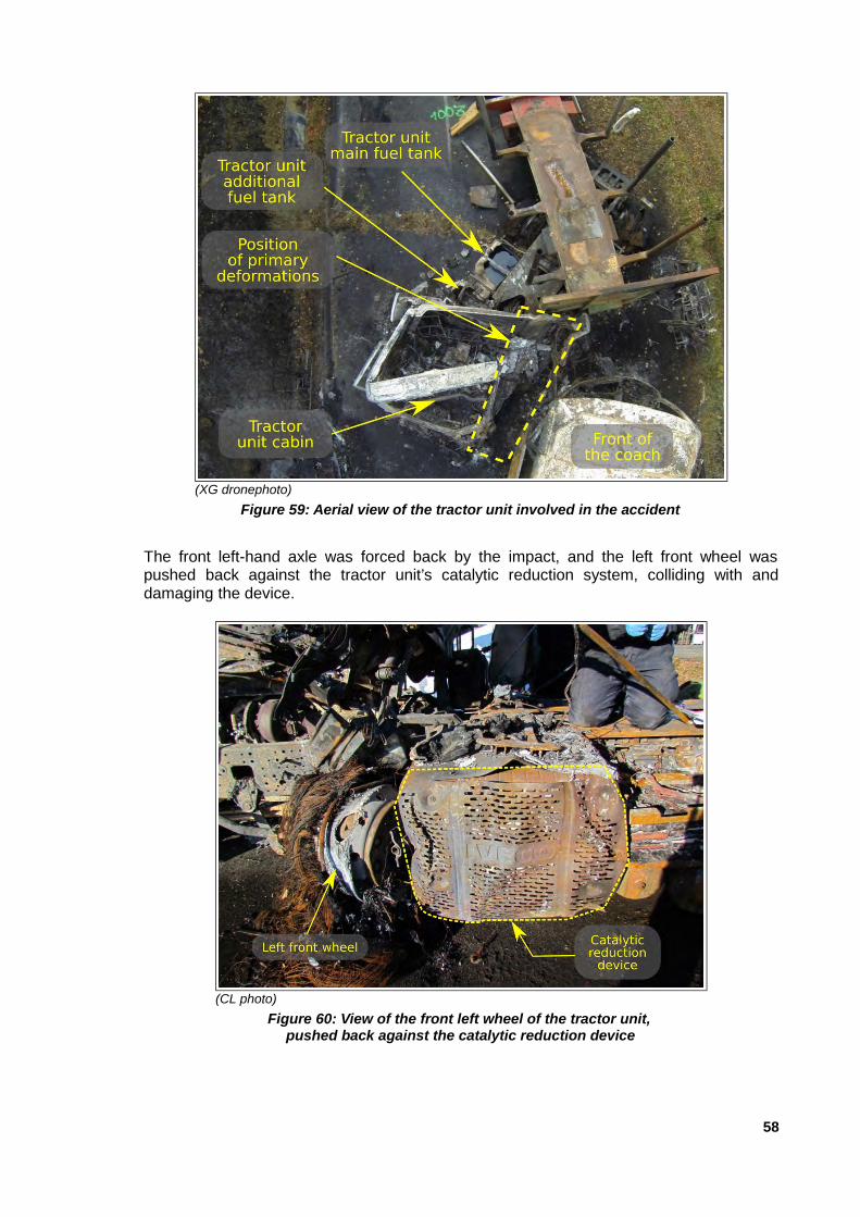
The front left-hand axle was forced back by the impact, and the left front wheel waspushed back against the tractor unit’s catalytic reduction system, colliding with anddamaging the device.
58
(XG dronephoto)
Figure 59: Aerial view of the tractor unit involved in the accident
(CL photo)
Figure 60: View of the front left wheel of the tractor unit, pushed back against the catalytic reduction device

The lower portion of the steering unit cracked open, releasing some of the oil containedinside (oil type ATF DEXRON II D).
Due to the extent of the damage caused by the fire, BEA-TT investigators were unable todetermine whether, at the moment of impact, a rupture of the engine lubrication andcooling circuits, as well as the air conditioning circuits and clutch control, occurred.
The primary fuel tank was partially melted. Traces indicating the level of liquid the tankcontained were visible on the tank’s interior after the fire had been extinguished. Theywere situated around 3/4 of the way up the tank.
Figure 62 below shows these traces on the inside of the main fuel tank.
59
(police photo)
Figure 61: View of the right-hand side of the tractor unit involved in the accident
(BEA-TT photo)
Figure 62: View of the traces of liquidon the interior of the primary fuel tank
of the tractor unit involved in the accident
Niveau de carburant

The additional fuel tank was almost completely melted. Only its right-hand side, supportstructure and the metallic straps holding it in place survived the fire. The right-hand side ofthe tank showed traces of molten metal and signs of metal splitting.
No liquid level was visible on the walls of the additional tank.
The rear side of the driver’s cab showed major signs of localised fire, mainly on its left-hand side.
A metal rod, which had been stored in a boot space on the left-hand side of the driver’scab, perforated the rear of the cab; one end of the rod was found where the additional fueltank had been, in a position that led investigators to surmise that it had partially perforatedthe tank.
60
(police photo)
Figure 63: Close-up view of the additional fuel tankon the tractor unit involved in the accident
(police photo)
Figure 64: View of the left-hand side of the tractor unitinvolved in the accident

(police photo)
Figure 65: Close-up view, from the rearof the tractor unit, of the metal rod
that passed though the rear wall of the cab
(police photo)
Figure 66: Close-up view, from the frontof the tractor unit, of the metal rod
that passed through the rear wall of the cab.
3.4.5.3 - Analysis of data recorded by the tractor unit’s tachograph
The tractor unit’s tachograph was completely destroyed by the fire. Investigators weretherefore unable to carry out any examination of the data recorded by this device.
3.4.6 - Expert analysis of the semitrailer and its components
3.4.6.1 - Tyres
The vehicle was connected to the road via six tyres and three axles. The tyres werepositioned according to the diagram below.
The semitrailer’s tyres were slightly worn. Their dimensions are in compliance withapproved limits, and the tyre pressure was correct.
Isolated abrasions on the tyre treads were observed on tyres 1D and 2D, whose shapecorresponds approximately to the area where the tyre met the road surface. The abrasionson these tyres can be matched with the tyre tracks caused by slippage observed on theroad surface (cf figure n° 9).
61
(FB document FB annotated by BEA-TT)
Figure 67: Position of tyres on the semitrailer

These tyre abrasions are visible in figures 68 and 69 below.
3.4.6.2 - Coupling
No anomalies were observed on the vehicle’s coupling pivot. Examinations carried outfollowing the accident showed that the semitrailer remained coupled to the tractor unit.
3.4.6.3 - Suspension
No irregularities were observed on the vehicle’s suspension.
3.4.6.4 - Braking
The semitrailer was equipped with disc brakes on each wheel, activated by a pneumaticsystem fitted with an anti-lock braking device (ABS).
Measurements of thickness of the brake pads and discs showed no irregularities.
However, an examination of the braking system did show several issues, summarisedbelow:
➢ significant cracking in the brake discs on wheels 1G, 1D and 3G;
➢ brake protection discs were eroded and perforated by corrosion, or missing, on wheels1G, 1D, 3G and 3D;
➢ the brake clamp devices were defective or unusually worn on wheels 1D, 2D, 3G and3D;
➢ the second brake fluid reservoir was severely corroded;
➢ the ABS sensors were the wrong way round on the right wheels of axles 1 and 3,
➢ insufficient braking efficiency on the right wheels of axles 1 and 2 was observedfollowing the accident.
The analysis of the consequences of these issues led the judicial expert to surmise thatonce the semitrailer’s ABS had been activated, the braking power was only sufficient onthe vehicle’s left-hand side; this imbalance caused, at the level of the coupling pivot, aresulting force towards the outside of the bend, pushing the rear of the tractor unit in thisdirection, and thereby either causing or exacerbating the jack-knifing of the lorry.
62
(CL photo)
Figure 68: Abrasions on the tyre treadsof tyre 2D.
(FB photo)
Figure 69: Abrasions on the treads of tyre 1D

The operational procedures for technical inspections currently do not allow for thedetection of inversely-installed ABS sensors. However, modifications introduced by agovernment Decree issued on June 8th 2017 will make such detection possible as of May20th 2018 (the date on which the Decree takes effect).
3.4.6.5 - Damage to the semitrailer
The semitrailer shows damage caused partly by the impact with the rear panel of thetractor unit, and partly by the fire that broke out following the collision.
The damage to the semitrailer caused by the impact with the rear of the tractor unit’scabin was localised around the upper portion of the trailer’s front panel, which was pushedbackwards.
The fire destroyed part of the semitrailer, along an area extending from the front panel tothe stabilisers. The combustible materials found in this zone were burned in the fire. Thisincludes electrical cable casings and the tubing for the pneumatic braking system.Components made of aluminium alloy in this zone also melted or disappeared.
The second trailer17 post on the right-hand side of the vehicle fell onto the road, as a resultof its support structure giving way.
3.5 - Kinematic reconstruction of the accident
Upon the request of the Assistant Public Prosecutor from the high court of Libourne, akinematic reconstruction of the accident was compiled by an accident expert using PC-Crash© analytical software.
17 Post (steel or aluminium) found on the perimeter of the semitrailer’s loading panel.
63
(CL photo)
Figure 70: View of the right-hand side of the semitrailer involved in the accident

The theories posited by the judicial expert and the conclusions of this reconstruction arepresented below. The figures illustrating the conclusions are also drawn from the digitalsimulation which was compiled for the investigation.
However, it must be underlined that the vehicles’ initial speeds, as well as their speeds atthe time of impact, are only estimates calculated by the software based on theoreticalinformation gathered by the vehicle expert, and that investigators were not able to gatherany solid information regarding the vehicles’ speeds from the on-board speedometers ortachographs, as these devices were completely destroyed in the fire.
The positions and speed of the vehicles in the moments leading up to the crash, and atthe moment of impact, have been reconstituted based on vehicle characteristics, roadsurface modelling, the positions in which the vehicles were found, analysis of tyre tracksfound on the road surface, and identification of the points of impact and directionality ofthe collision.
3.5.1 - Final position of vehicles and tyre tracks on road surface
Traces of tyre slipping and wheel locking, as well as the final position of the vehicles, areshown in figure 71 blow, as well as in figures 4, 8 and 9.
64
(CL document annotated by BEA-TT)
Figure 71: Representation of tyre tracks found and final position of the vehicles at the scene of the accident

Please note: the simulation software retains the dimensions and shapes of the vehicles.As such, these representations do not show damage and deformations caused by thecollision.
The position and type of tyre tracks found (slipping and wheel locking) allowed BEA-TTinvestigators to observe:
➢ assuming that the lorry was travelling in its own lane, that track 1, which begins furthestaway from the accident, corresponds to slipping of one of the lorry’s left wheels,
➢ that this track, which shows continuous slipping and continues beyond the wheels of thesemitrailer, was left by a left wheel of the tractor unit;
➢ that tracks 2 and 3 were most likely caused by locking of wheels 1D and 2D of thesemitrailer, given the abrasions observed on their tyres;
➢ that track 4, which appears beyond the wheels of the semitrailer, was caused by theslipping of one of the tractor unit’s wheels. Taking into account its proximity to the roadedge, it was mostly likely left by one of the tractor unit’s left rear wheels.
3.5.2 - Identification of impact points and directionality
Based on the examination of damage to the vehicles, the expert made the followingobservations.
The tractor unit showed signs of frontal impact on roughly 1/4 of its front left-hand side;the primary direction of the force exerted on the vehicle being roughly between 11 o’clockand 12 o’clock.
The coach shows signs of front impact on around 1/4 of its front left-hand side; theprimary direction of the force exerted on the vehicle being at roughly 12 o’clock.
65
(CL document)
Figure 72: Direction of impact on the coach
(CL document)
Figure 73: Direction of impact on the tractor unit

3.5.3 - Vehicle 3D Modelling
The geometry of the articulated lorry was calculated using the values provided by itsmanufacturer. In the event that any measurements did not match, the investigating expertused his own measurements taken at the scene.
The geometry of the coach was calculated using the values provided by its manufacturer.These were in accordance with the measurements taken by the investigating expert.
The position of the fifth-wheel coupling on the articulated lorry, as well as the centres ofgravity for each vehicle, were determined by the investigating expert using data providedby the manufacturers, supplemented by measurements taken over the course of variousassessments of the accident.
3.5.4 - Results
The expert tested various movement scenarios for each vehicle in order to reproduce theirkinematics and trajectories in the moments leading up to the impact. These scenarioswere configured in such a way as to accurately represent the braking performance of thearticulated lorry, its passage through the tyre tracks observed, its jack-knifing just beforeimpact, the configuration of the collision, the final position of the vehicles and estimatedenergy dissipation.
The scenario which best represented these fixed values was retained.
The results obtained were as follows:
➢ the initial speed of the articulated lorry was around 75km/h, slowing to around 35km/h atthe moment of impact;
➢ the initial speed of the coach was around 45km/h, slowing to 15km/h at the moment ofimpact.
The positions of the vehicles (according to 3D modelling based on the reconstruction ofthe accident) at the moment when the coach driver first saw the articulated lorry when thetwo vehicles where at least 40m away from each other, and then at the moment of impact,are shown in figures 74 and 75 respectively.
66
(CL document)
Figure 74: Position of the vehicles at t = 4.50 s,at the moment when the coach driver first saw the articulated lorry.

The simulation allowed BEA-TT investigators to gain an appreciation of the speed atwhich each vehicle was travelling, but it remains difficult to show how precise thisinformation is.
Nevertheless, analysis of the tracks left by tyre slipping on the road surface have allowedBEA-TT investigators to conclude that they were caused by the articulated lorry driftingdue to dual forces: a significant centrifugal force caused by excessive speed going intothe bend, and locking of the driving wheels towards the right as the vehicle attempted toavoid going off the road.
3.6 - Outbreak and spread of the fire
Various theories regarding the outbreak and spread of the fire inside the coach have beenput forward by the different parties involved in the judicial inquiry into the accident.
The main theory (upheld by the fire expert in his report dated January 24th 2016) is that aspray of diesel was generated when the additional fuel tank (located behind the tractorunit’s cabin) was pressurised during the crash impact and then perforated by a metal rod.This spray was immediately ignited upon contact with an unidentified heat source, and theresulting ”fireball” then penetrated the interior of the coach via the opening created by theshattering of side windows on the front left-hand side of the coach, near the driver’sposition.
The report also pointed to the bursting of heating and air conditioning pipes located at thefront of the coach, which then released coolant and refrigerant fluids onto the area ofoverlap between the coach and the tractor unit; however, the role played by the projectionof these fluids in the outbreak and spread of the fire has not been fully analysed.
The judicial expert responsible for analysing the vehicles observed that the coach’s leftfuel compartment was severely damaged during the collision, leading to an unexpectedcompression of the polyethylene fuel tank inside. His analysis did not examine this pointfurther, but did recommend that additional investigations be carried out in order to identifythe behaviour of the coach’s fuel tanks under the pressure generated by the collision.
67
(CL document)
Figure 75: Position of the vehicles at the moment of impact (t = 6.275 s)according to the kinematic reconstruction.

The judicial expert responsible for examining the vehicles also observed that a rupture inthe tractor unit’s transmission could have led to a leak or projection of transmission fluid.He also concluded that, given the magnitude of the damage observed on the tractor unit,a rupture or ruptures of the radiator and cooling pipes, the air conditioning system and thehydraulic clutch circuits might have occurred during the impact. The fluids released by thistype of damage could also have played a role in the outbreak and /or spread of the fire.
The analyses carried out and the theories retained by the BEA-TT investigators arepresented in the next part of this chapter.
According to witness statements taken, the vehicles involved in the accident were both inoperation and collided with their engines running. All the circuits (fuel, lubrication, cooling,air conditioning and electronics) in their respective engines were live when the accidentoccurred; depending on their individual states, these circuits all represent potentialsources of the fire or may have helped to spread it.
3.6.1 - Fuel supply sources
In the area of impact between the two vehicles or in the immediate vicinity there areseveral potential fuel supply sources, in particular:
➢ the main fuel tank of the tractor unit;
➢ the tractor unit’s additional fuel tank located behind the driver’s cab, above the exhaustline;
➢ the tractor unit’s steering unit, which contained an ATF DEXRON II D type of oil;
➢ the lubricating and cooling systems of the tractor unit’s engine;
➢ the tractor unit’s air conditioning;
➢ the coach’s left fuel tank
➢ the coach’s air conditioning system and in particular the evaporator installed in front air-conditioning unit, in which the refrigerant enters in a liquid state under high pressure;
➢ the coach’s heating system and in particular the radiator installed in the same front unitin which the refrigerant circulates.
68

The main fuel tank of the trailer truck was partially melted. It was not located in thedirect area of impact. It was not distorted. The damage it suffered is as a result of the fire’sthermal radiation.
The articulated lorry’s additional fuel tank was directly hit during the collision.
The observations made by the BEA-TT on the remains of this tank are the following:
➢ the tank has almost completely melted, only its right part, its support and the metallictie-down straps have been preserved from the fire;
➢ the location of the traces of molten aluminium found on the chassis of the tractor unit aswell as the condition of the tank’s metallic tie-down straps show that the left part of thetank pivoted backwards before melting;
➢ the right part of the intact tank has traces of melting as well as traces of tearing of themetal;
➢ the left side of the tank located at the metal rod that perforated the rear of the driver'scab has melted.
69
(photo French Gendarmerie.)
Figure 76: View of the diesel fuel tanks of the accident-damaged tractor unit

Given the deformations observed on the tank and the position of the driver's cab of thetractor unit, which was found by the front panel of the semi-trailer, the BEA-TT thinks thatthis tank was most likely broken upon impact, crushed between the rear of the semi-trailer’s cab and front panel, releasing its fuel.
70
(police photo.)
Figure 77: View of the additional tank of the accident-damaged tractor unit
(police photo.)
Figure 78: Rear view of accident-damaged tractor unit

This tank could have also be perforated by a metal rod which was stored in a trunk in thedriver's cab of the tractor unit. This metal rod in fact perforated the rear of the driver's caband its rear part was found at a location where the additional tank had been installed andin a position suggesting that it could have partially penetrated it.
For the BEA-TT investigators, the highly probable rupture of this tank and the existence ofan anti-overpressure plug are not compatible with the hypothesis of the pressurisation ofthe fuel it contained, which would have been capable of generating a diesel oil nebulisate.
The left fuel tank of the coach is made of polyethylene and has been completelyburned. There are no usable parts left. This tank was located in the direct area of impactin which the metal structures of the coach which protected it were extensively crushed. Itis therefore very probable that this tank did not withstand the impact and that it brokeduring the collision, releasing its fuel which then spread to the ground.
71
(police photo.)
Figure 79: View of the left frontof the accident-damaged coach
(photo CL)
Figure 80: Close-up view of the front left-hand sideof the coach involved in the accident

The air conditioning components of the coach that contained the refrigerant in liquidphase under pressure do not appear to have been directly impacted during the collision,but were damaged by the resulting fire. It is therefore very probable that the refrigerantcontained in them, in this case R134a, which is furthermore very difficult to ignite, did notplay a role in triggering the fire.
The heating system components of the coach situated in the front housing do notappear to have been directly impacted during the collision, but were damaged by theresulting fire. It is therefore very probable that the liquid contained within them, namelyGlysantin G48, which is furthermore difficult to ignite, did not play a role in triggering thefire.
The mechanical components of the tractor unit were severely damaged by the fire whichstarted after the collision, and apart from the steering unit which broke at the moment ofimpact, releasing some of the oil it contained, it was not possible for the BEA-TTinvestigators to determine whether other mechanical components of this tractor unit brokeduring the collision.
It should be noted, however, that the tractor unit’s air conditioning system containing theliquid-phase pressurised refrigerant, the engine, the gearbox and the cooling systemcontaining various potentially flammable fluids do not appear to have been impactedduring the collision, but were rather damaged or destroyed by fire.
72
(police photo.)
Figure 81: View of the front faceof the accident-damaged coach

3.6.2 - The heat source at the origin of the blaze
In the area of impact between the two vehicles, or in close proximity,there are numerouselectrical systems as well as significant heat sources, in particular:
➢ the highway tractor’s exhaust system was designed to meet the Euro 618 standard andcan reach high temperatures of several hundreds of degrees due to the temperature ofthe exhaust gas at the immediate exit of the engine;
➢ the device for selective catalytic reduction fitted to the tractor unit;
➢ the coach’s electrical panel located at the front left between the pressure taps and thefront left fuel tank;
➢ the batteries of the coach and of the tractor unit.
It should also be pointed out that during the collision, the crushing or friction of variousmetal parts of the vehicles against each other or on the surface of the road could havegenerated active sources capable of igniting a fuel present in the vicinity that had alsobeen heated previously by coming into contact with the hot parts of the vehicles.
The BEA-TT inspected the remains of the coach's electrical panel located at the front left,in front of the its left fuel tank and did not find any melted parts on the remains of theelectrical wires, which are characteristic of a short circuit. It also inspected other electricaland heat sources that could have played a role in triggering the fire but was unable toformally identify a source for the origin of the fire.
3.6.3 - The hypothesis concerning what triggered the fire and caused it to spread
BEA-TT investigators point out that the significant damage to the vehicles limited thepossibilities for investigations, and it is therefore not possible to determine with absolutecertainty what caused the fire to start and spread so quickly.
18 European emission standards known as "Euro standards", are the European Union regulations which set themaximum polluting emission limits for motor vehicles
73
(Document IV annotated by BEA-TT)
Figure 83: Layout of the tractor unit’s engine,gearbox and tank (top view)
(Document IV annotated by BEA-TT)
Figure 82: Layout of the tractor unit’s airconditioning unit in the cab (top view)

Given its investigations and analyses presented in the previous paragraphs, afterexamining the various hypotheses mentioned, the BEA-TT favours the following scenario,which it deems to be the most plausible.
Upon impact, the tractor unit’s additional tank and the coach’s left tank broke and spreadtheir contents on both vehicles and the roadway.
The contents of the additional tank located behind the driver's cab spread over the rear ofthe cab and on the mechanical components of the tractor unit underneath it. It spread inparticular over the exhaust line and the catalytic reduction device, which are heated tovery high temperatures during operation. This may have led to heating and partialvaporisation of the diesel oil.
The diesel oil contained in the coach’s left tank spread over the road and flowed towardsthe tractor unit, following the slope of the road.
The active heat source responsible for the blaze could not be formally identified, butperhaps the crushing or friction of the various metallic and electrical components of thevehicles against each other or on the roadway were able to generate active heat sourcesthat could have ignited the diesel oil and its fumes. This could have easily happened asthe latter could have been preheated and vaporised upon contact with the tractor unit’sexhaust line and selective catalytic reduction device.
Given the volume of these two tanks, although we do not know how full they were at thetime of the accident, it can be assumed that several hundred litres of fuel spread andbecame ignited. The flames then spread under the tractor unit to the coach’s tanks andentered the coach through the front left windows on the driver's side that had broken atthe time of the collision.
Given the calorific value of this fuel and the amount involved, the fire quickly spread to thecoach, melting and igniting its interior fittings, consisting mainly of ABS19, polypropylene,polyester and polyurethane. The hot fumes and the highly toxic combustion gases thatwere released and quickly spread from the front to the back of the coach contributed tothe conflagration of the coach.
The fire quickly became uncontrollable.
3.7 - Current regulations for public transit vehicles in terms of layout,fire risk and design of exits
In general, the vehicle regulations applied to a vehicle are those applicable on the date ofits entry into service. The various regulations are constantly evolving.
The global technical harmonisation of vehicles is guided by a founding internationalagreement which establishes harmonised provisions on a worldwide scale guaranteeing inparticular a minimum degree of safety.
This is the agreement of the United Nations Economic Commission for Europe (UNECE)on the adoption of uniform technical requirements for motor vehicles, equipment and partsthat may be fitted or used on a motor vehicle and the conditions for mutual recognition ofapprovals issued in accordance with these requirements, commonly known as the"revised 1958 Agreement". VARIOUS UN regulations are annexed to this agreement, aswell as the list of the contracting parties that signed them.
19 ABS or acrylonitrile butadiene styrene is a thermoplastic polymer that is often used in automotive construction.
74

Under the 1958 Agreement, a Contracting Party applying one or more of the UNRegulations annexed to the Agreement shall be entitled to grant type approvals forvehicles, their equipment and components referred to in those Regulations and shallaccept the type approval of any other Contracting Party which has adopted the sameRegulations.
The reciprocal recognition of type approvals between the Contracting Parties whoimplement the regulations facilitates the trade in vehicles on the international market.
This global regulation is transposed at the European Level by various Europeanregulations and directives and at the national level in France by the amended decree of 2July 1982 on the public transport of persons with regard to the part relating to theconstruction and layout of public transport vehicles.
Other regulatory areas (such as breaking and noise level) are transposed by specificnational regulations and more generally by the decree of 4 May 2009 on type approval ofmotor vehicles, their trailers and systems and equipment intended for such vehiclespursuant to Directive 2007/46/EC.
The regulation of the European Parliament and of the Council regarding the areasanalysed in this report is regulation no. 661/2009 of 13 July 2009 as amended regardingthe type approval requirements for the general safety of motor vehicles and their trailersand systems, components and separate technical units intended for them.
In particular, regulation no. 661/2009 repealed, with effect from 1 November 2014, thefollowing three European Directives which were applicable for the EC type approval ofnew vehicles:
Provisions concerning all motor vehicles:
➢ Directive 70/221/EC of 20 March 1970 on the approximation of the laws of the MemberStates relating to liquid fuel tanks and rear protective devices for motor vehicles andtheir trailers (amended by Directive 2000/8/EC of 20 March 2000) ;
Provisions concerning coaches:
➢ Directive 2001/85/EC of 20 November 2001, on the special provisions for vehiclesintended for the transport of passengers and comprising, in addition to the driver's seat,more than eight seats(amended by Directive 2006/96/EC of 20 November 2006);
➢ Directive 95/28/EC of 24 October 1995 on the burning behaviour of materials used inthe interior fittings of certain categories of motor vehicles.
For the EC type approval of new vehicles, Regulation 661/2009 also made the provisionsof certain UNECE regulations mandatory, and in particular with regard to the areasanalysed in this report, the following regulations:
Provisions concerning all motor vehicles:
➢ UNECE Regulation No. 34 on uniform provisions for the approval of vehiclesconcerning the prevention of fire hazards;
Provisions concerning coaches (vehicles of international categories M2 or M3):
➢ UNECE regulation no. 107 on uniform requirements for type approval of vehicles ofcategories M2 and M3 (vehicles for the carriage of passengers and comprising, inaddition to the driver's seat, more than eight seats) as regards their generalconstruction characteristics;
75

➢ UNECE regulation No. 118 on the uniform technical requirements concerning theburning behaviour and/or the capability to repel fuel or lubricant of materials used in theinterior fitting of certain categories of motor vehicles.
Any manufacturer wishing to register a new vehicle in one of the countries of theEuropean Union must have previously obtained type-approval at European level,according to Directive 2007/46, which implies compliance in particular with the UNECERegulations referred to above. Individual or small-scale national type approval accordingto the decree of 4 May 2009 is also possible but the applicable rules are identical for theabove-mentioned areas.
3.7.1 - Tanks and auxiliary liquid fuel tanks
The corresponding requirements are contained in UNECE Regulation No. 34 on uniformprovisions for the approval of vehicles concerning the prevention of fire hazards.
These requirements were also specified in Directive 70/221/EC of 20 March 1970, whichhas been recently repealed.
These requirements state that fuel tanks shall be mounted in a way that it is protectedfrom the effects of a frontal collision, lateral collision or a collision occurring at the rear partof the vehicle.
For the purpose of their approval, as regards the prevention of fire risks in the event of acollision, M3 category vehicles (passenger vehicle with more than 8 seats in addition tothe driver’s seat and a maximum weight exceeding 5 tonnes) may, at the manufacturer'srequest, be subjected to a frontal collision test against a barrier, with an impact speed ofaround 50 km/h.
At the end of the test, the tanks should not leak. Only slight leakage of liquid in the fuelinstallation during the collision is permitted.
3.7.2 - Prevention of fire risks in coaches
In the current regulations, irrespective of the specific provisions concerning the insulationof potential sources of fire in a coach, the risk of fire for this type of vehicle is dealt with inUNECE regulation no. 118 on uniform technical requirements concerning the burningbehaviour and/or the capability to repel fuel or lubricant of materials used in the interiorconstruction of certain categories of motor vehicles.
The risk of fire was also dealt with in the recently repealed European Directive 95/28/ECof 24 October 1995.
The materials used in the construction of the coach’s inside bodywork must satisfy anumber of requirements, the main one being that they should not exceed a combustionrate of 100 millimetres per minute under the test conditions described.
On the other hand, the regulations do not specify any toxicity requirements for fumes fromcombustion of these materials.
3.7.3 - Design of coach exits
The corresponding requirements are contained in § 7.6 of Annex 3 of UNECE regulationno. 107 on uniform provisions for the approval of vehicles of categories M2 and M3, withregard to their general construction characteristics.
76

For vehicles designed exclusively for the carriage of seated passengers, the minimumnumber of doors to be fitted to the vehicle shall be two: either two service doors, or oneservice door and one emergency door. 0% of service doors must be located on the sidecorresponding to the traffic direction in the country where the vehicle is to be licensed. Atleast one service door must be located in the front half of the vehicle.
In addition, every public transport vehicle must have a minimum number of exits,consisting of the doors described above and emergency windows (all the escape hatchesalso count as an emergency exit). This minimum number of exits depends on the numberof seats in the vehicle.
3.7.4 - Interior lighting and emergency lighting for coaches
The bus, commissioned in January 2011, was not equipped with emergency lighting.
Its type had been approved in France in accordance with the provisions of the ministerialdecree of 2 July 1982 on public transport. It should be noted that this decree, whichprescribes, in particular, the rules relating to the construction, fitting-out, equipment andmaintenance of vehicles, does not lay down any obligation relating to the installation ofemergency lighting.
The coach involved in the accident had obtained a certificate of conformity for its type. Itwas therefore in conformity with the French regulations.
For coaches which have been put into service since then, the corresponding requirementsconcerning interior lighting are contained in § 7.8 of Annex 3 of UNECE regulation no. 107on uniform provisions for the approval of vehicles of categories M2 and M3, with regard totheir general construction characteristics.
Appropriate interior lighting shall be provided to illuminate stairways, steps, access to exitsand their immediate surroundings, internal controls of all exits, and all areas withobstacles.. The vehicle shall be equipped with two interior lighting systems so that thefailure of one system does not affect the other systems.
The regulation also specifies that vehicles of classes II, III and B must be equipped withan emergency lighting system that can be switched on by the driver when he/she is sittingin his/her seat. In addition, the operation of the emergency control of any service oremergency door must turn on the emergency lighting system. This new requirement hasbeen incorporated into a recent amendment to UNECE Regulation No. 107.
This system must be able to remain on for at least 30 minutes and its power supply mustbe designed in such a way so as to minimise the risk of compromising its operation afteran accident.
All units that provide emergency lighting must produce white light. The Regulation doesnot specify their location in the passenger compartment of the vehicle but specifies aminimum illumination level of 10 lux at a height of 75 cm above the aisles and 1 lux at thefloor level, as well as rules regarding uniformity of illumination.
3.8 - Emergency evacuation procedure
There is no text on the arrangements for the emergency evacuation of passengers.
There is no provision for passenger information (other than the writing on emergencyexits) or specific training for the driver within the training to receive a driving licence orwithin the mandatory minimum initial training (FIMO).
77

However, the manuals for use by trainers give some instructions for rapid evacuationunder normal conditions (if the coach is not overturned): immediate evacuation at thedriver's request in the event of a fire and passengers’ exit rank according to their positionin the coach.
In response to a recommendation from the BEA-TT, in 2016, the French NationalFederation of Passenger Transport (FNTV) developed a brochure to raise awareness ofthe safety of passengers in coaches, which outlines the safety rules to be observed onboard a coach and the instructions for evacuation in case of an emergency20. Thisdocument is intended to be made available to each passenger in front of his/her seat.However, it would be useful if it were supplemented by a description of the procedure tobe followed in the event of a fire in the passenger compartment of the coach.
3.9 - Similar accidents
Coach fire that took place on 23 February 2008 on the A43 motorway near thevillage of Les Marches in Savoie
The BEA-TT conducted an investigation into a coach fire on 23 February 2008 on the A43motorway near the village of Les Marches in Savoie, which fortunately did not cause anycasualties.
It involved of a 91-seater double-decker coach carrying 52 people, which was completelydestroyed by the fire.
The investigations carried out showed that the fire was the consequence of thedisconnection between the coach’s heating system boiler and its exhaust pipe whichoccurred during a collision that same morning and was not detected.
In its report published in June 2009, the BEA-TT had identified three aggravating factors:
➢ the absence of an automatic fire detection system;
➢ the vulnerability of coaches to fire (flammability of materials, general layout);
➢ the presence of only one staircase to evacuate the upper floor.
The BEA-TT made a number of recommendations regarding automatic fire detection andextinguishing systems in public passenger transport vehicles, the fire resistance ofmaterials used in vehicle construction and evacuating the upper level of double-deckercoaches.
In particular, the BEA-TT recommended to the DSCR to support, in the context of therevision of UNECE regulation no. 118, the project to strengthen the requirementsconcerning the burning behavior of materials used in vehicle construction.
The main changes to this regulation should particularly include:
➢ the maximum burning rate of materials should be lowered from 100 to 75 millimetresper minute;
➢ the requirement for combustion tests to take into account the vertical combustionvelocity as a replacement for the horizontal combustion rate for all materials installed inthe vehicle in a position other than horizontal.
20 The brochure prepared by the FNTV is attached as Appendix 10 to this report
78

A joint proposal by France and Germany, to which Norway and Sweden joined,incorporating the two above developments, was presented at the October 2009 session ofthe Working Party on General Safety Provisions (GRSG)21.
UNECE regulation no. 118 was amended in 2013. The amended regulation specifies twoseparate tests depending on the horizontal or vertical position of the materials installed inthe interior compartment of the vehicle, but does not lower the maximum combustionspeed from 100 to 75 millimetres per minute. It should also be noted that other changeshave also been introduced to integrate the electrical cables and various impregnabilitytests of the materials present in the engine compartment.
Accident on 31 July 1982 on the A6 near Beaune
It is also worth mentioning the accident that occurred on 31 July 1982 on the A6 motorwayin the village of Merceuil in Côte-d’Or, which resulted in the death of 53 people, including44 children and adolescents, most of whom were on board a coach that caught firefollowing the accident.
This coach was travelling in convoy with a second coach. Both coaches had left the townof Crépy-en-Valois, about sixty kilometres north of Paris, the evening before, to takeyoung people and their instructors to a summer camp in Aussois, Savoie. The convoy hadtaken the A6 motorway towards Lyon.
Near Beaune, during a slowdown on a section of highway where three lanes merged intotwo, a pileup involving a dozen vehicles including the two aforementioned coachesoccurred.
During the pile-up, the tank of a light vehicle broke and spread its contents on the road.The spilled fuel ignited. Seven of the ten vehicles involved caught on fire.
The first coach that caught on fire from the rear could be completely evacuated through itsfront right door.
The second coach caught fire from the front. The right front door was blocked by a lightvehicle that had crushed against it, so evacuation could only be done through the rearright door after being opened by the driver.
Fifteen out of 59 young people and one instructor out of five adults managed to get out ofthe vehicle before the smoke from the fire made the evacuation impossible, within atimeframe estimated by the Commission of Inquiry set up by the Minister of Transport ofabout 2 minutes.
The Commission considered that there were various risk factors that could have occurredover the course of the accident, and it was not possible to weigh them and prove that oneor another of them had a more decisive effect than others in the sequence of events.
The Commission made 66 proposals divided into 8 themes:
➢ infrastructure and signing;
➢ the supervision and control of traffic, the organisation of emergency exits;
➢ the traffic;
➢ the vehicles;
21 The Working Party on General Safety Provisions (GRSG) is the subsidiary body of the World Forum forHarmonization of Vehicle Regulations (WP.29), which prepares general safety regulatory proposals in WP.29. Thisgroup of experts conducts research and analysis to develop general safety requirements for vehicles, particularlybuses and coaches.
79

➢ the people;
➢ controls and penalties;
➢ the organisation of long-distance transport for children;
➢ mobilisation, information.
In particular, the Committee proposed the following measures:
Concerning the protection of coaches against fire
➢ that the standards applied by builders and manufacturers for the fire resistance ofmaterials used in the interior fittings of vehicles and seat upholstery are verified(limitation of the combustion rate measured according to the ISO 37 95 standard) andthat stricter standards are, where appropriate, laid down by regulation;
➢ that studies are conducted on the possible toxicity of chemical compounds released bythe rapid combustion of these materials when subjected to a fuel fire;
➢ that full-scale experiments be carried out to determine, under real conditions, how longit takes to evacuate a coach and the speed of propagation of an internal fire started bya gasoline fire.
Concerning emergency exits
➢ check that the European emergency exit regulations allow for a sufficiently rapidevacuation through the doors, in particular by testing the possible obstruction of theiraccess by seats that are retractable or removable to some extent;
➢ that the conditions for manoeuvring and opening the emergency exits are brought to theattention of adult travellers and children's escorts;
➢ that the operating mechanism of the doors be re-examined in light of, in particular, theconstraints in normal operating conditions, inadvertent openings and emergencyevacuation.
The main regulatory measures taken following the accident included:
➢ a reduction in the maximum speed permitted for coaches;
➢ a reduction of the maximum speed permitted for all vehicles in rainy weather;
➢ the prohibition of the collective transportation of children during the peak summer travelperiod;
➢ the installation of an inviolable speed limitation device on heavy-good vehicles andcoaches.
80

4 - Analysis of the course of the accident and rescue operations
4.1 - The route of the vehicles before the accident
4.1.1 - The route of the articulated lorry
On 23 October 2015, the day of the accident, the driver of the articulated lorry began hisday around 5.30 a.m. After spending the night in the cab of his articulated lorry with hisyoung son, which was parked in the car park of a restaurant in Coutras in Gironde (33), hewent to the premises of a company in Saint -Michel-de-Montaigne in Dordogne (24) inorder to deliver a load of lumber. He arrived in Saint-Michel-de-Montaigne around6.00 a.m. and left around 7:00 a.m. after unloading his cargo.
After crossing the town of Castillon-la-Bataille, he continued his route by taking the RD 17towards Puisseguin.
4.1.2 - The route of the coach
On 23 October 2015, the day of the accident, the coach driver went on duty around6.15 a.m. He picked up his vehicle which had been parked since Wednesday, 22 Octoberaround 7 p.m. in a car park near the town hall of Génissac in the Gironde department (33).He then went to Petit-Palais to take on his passengers, who he had to take to Arzacq-Arraziguet in the department of Pyrénées-Atlantiques (64), as part of an excursionorganised by the senior clubs of the villages of Petit-Palais-et-Cornemps and Saint-Sauveur-de-Puynormand.
He arrived at Petit-Palais around 7 a.m. AT 7.15 a.m., after 48 passengers had boarded,he continued his route to Arzacq-Arraziguet. After crossing the town of Puisseguin, hecontinued his route by taking the RD 17 motorway towards Castillon-la-Bataille.
It was dark and although it was not raining, the road was wet as it travels through aforested area.
4.2 - The collision and the ignition of the fire
The articulated lorry left its course as it approached a tight right-hand bend with a radiusof about 55 m at a speed estimated by the simulation of about 75 km/h.
The technical appraisals carried out on the road as a whole did not reveal any failure ofthe vehicle which could have been the cause of this departure from the trajectory.
The reasons for which the articulated lorry thus swerved are therefore very probablyrelated to a speed which is unsuitable for traffic conditions and the geometry of the road.
During the operation of the articulated lorry’s braking system, the defects observed on thebraking system of its semi-trailer could also have led to or favoured its jack-knife.
The coach driver, approaching the same bend at an estimated speed of 45 km/h, saw thearticulated lorry that was driving towards him in his lane.
He then braked and moved as far as possible to the right.
A few seconds after the collision, the sound of a flare was heard and flames appeared infront of the coach’s windscreen between the two vehicles.
81

4.3 - Evacuating the coach
After exiting his partly crushed driver's cab, the driver of the coach opened the front doorof his vehicle by operating the manual emergency opening system. He exited the busthrough that door and headed for the central door which he opened in the same way fromthe outside.
The passenger who was sitting on the right-hand side of the window seat immediatelybehind the side door in the middle of the coach, was thrown down the stairs after theguardrail that was in front of her broke.
A passenger used an emergency hammer to break the window located at the side door inthe middle of the bus that was not open and so the passengers could escape from theburning coach through the hole thus formed.
Apart from the driver of the coach, only one passenger was able to use the front door ofthe vehicle to escape.
Six other passengers were able to evacuate the bus through the central corridor and theside door before the fire and the toxic gases released made it impossible to evacuate.
4.3.1 - Notification of emergency services
The alert was given at 7:30 a.m. by someone who had witnessed the accident and calledGironde department’s fire and rescue call centre.
The first emergency fire truck belonging to the Castillon-la-Bataille rescue centre arrivedat the scene of the accident around 7:50 a.m.
The firefighters carried out a massive fire attack by means of two water hoses and a foamhose and gathered the victims of the accident in the premises of the village hall inPuisseguin, which they transformed into an advanced medical post.
The victims with minor injuries were then transported to Libourne hospital, those withmore serious injuries to the Bordeaux University Hospital.
The fire was reported as contained at 8.44 a.m.
4.3.2 - Assessment and location of victims
A total of 43 fatalities, 41 bus passengers and the two occupants of the articulated lorrywere recorded, and 8 were injured (4 with minor injuries and 4 seriously injured), includingthe driver and 7 coach passengers.
The body of the driver of the articulated lorry was found outside his driver's cab, betweenthe articulated lorry and the coach, at the foot of the driver's door of the articulated lorry.
The body of the passenger in the articulated lorry was found in the driver's cab of thearticulated lorry in the middle seat.
The bodies of some of the coach passengers were found sitting in their seats, but mostwere in the central aisle.
The location of the coach's 49 occupants at the time of the accident could not beaccurately determined, as passenger statements about their location were sometimescontradictory.
82
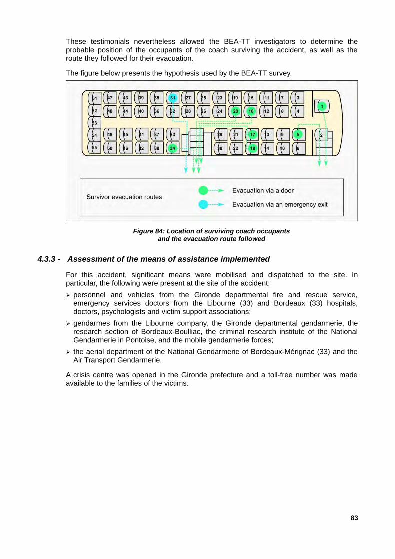
These testimonials nevertheless allowed the BEA-TT investigators to determine theprobable position of the occupants of the coach surviving the accident, as well as theroute they followed for their evacuation.
The figure below presents the hypothesis used by the BEA-TT survey.
4.3.3 - Assessment of the means of assistance implemented
For this accident, significant means were mobilised and dispatched to the site. Inparticular, the following were present at the site of the accident:
➢ personnel and vehicles from the Gironde departmental fire and rescue service,emergency services doctors from the Libourne (33) and Bordeaux (33) hospitals,doctors, psychologists and victim support associations;
➢ gendarmes from the Libourne company, the Gironde departmental gendarmerie, theresearch section of Bordeaux-Boulliac, the criminal research institute of the NationalGendarmerie in Pontoise, and the mobile gendarmerie forces;
➢ the aerial department of the National Gendarmerie of Bordeaux-Mérignac (33) and theAir Transport Gendarmerie.
A crisis centre was opened in the Gironde prefecture and a toll-free number was madeavailable to the families of the victims.
83
Figure 84: Location of surviving coach occupantsand the evacuation route followed
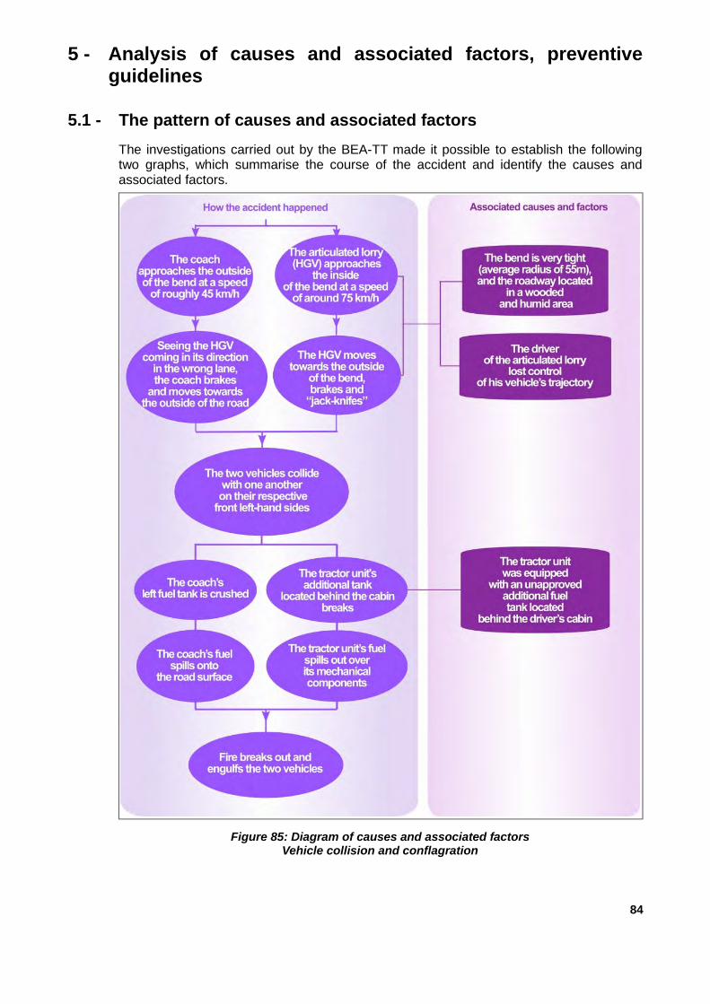
5 - Analysis of causes and associated factors, preventiveguidelines
5.1 - The pattern of causes and associated factors
The investigations carried out by the BEA-TT made it possible to establish the followingtwo graphs, which summarise the course of the accident and identify the causes andassociated factors.
84
Figure 85: Diagram of causes and associated factorsVehicle collision and conflagration

This analysis led the BEA-TT to seek preventive recommendations in the following 4domains:
➢ the signs for the bend;
➢ the additional fuel tanks;
➢ the burning behaviour of coaches;
➢ the smoke extraction and evacuation of coaches.
85
Figure 86: Diagram of causes and associated factorsFire and evacuation of the coach

5.2 - The signing for the bend
5.2.1 - Reminder of the findings
This right-hand bend is on a gentle incline, in the articulated lorry’s direction of traffic. Ithas an average radius of about 55 m to the right. It is preceded by a tight left-hand bend.
Moreover, the slope bordering the inside of the bend masks a large part, which reducesthe readability of the bend and the visibility of vehicles travelling in the opposite direction.
Given its geometrical characteristics, BEA-TT investigators consider that it cannot besafely crossed by a light vehicle at a speed greater than 50 km/h. This speed can also beachieved by applying the method outlined in the SETRA Practice Guide of July 2002entitled "How to Signpost Bends".
This 6-m wide bend presents particular difficulties for heavy-duty vehicles, which cannoteasily cross it. The road inside the bend does not have a drivable or other hard shoulder,but has an A2 type border (15X20X100 cm) and a ditch. The bend must therefore beapproached at a substantially lower speed.
In the traffic direction of the road, upstream of the area of the accident, the road exhibitsdefects in wheel rutting and wear of the lining at the passage points of vehicle wheels.
Since the tachograph of the articulated lorry was destroyed during the accident, it is notpossible to know the articulated lorry’s exact speed when it was approaching the last bendimmediately before the accident.
The kinematic reconstruction carried out by the judicial expert shows that the articulatedlorry approached this bend at a speed estimated at about 75 km/h.
It should be emphasised that this is only an estimate of the articulated lorry’s actualspeed, but these findings, however, suggest that the articulated lorry probably approachedthis bend at an inappropriate speed, leading to the loss of control of the vehicle.
5.2.2 - Analysis
Although no accidents have been recorded at this bend over the past 5 years, itsexamination shows that it presents particular difficulties for vehicles using this route:
➢ its radius is tight and appreciably lower than that of the bend preceding it;
➢ there is a slope bordering the inside of the bend which reduces its readability and thevisibility of vehicles travelling in the opposite direction;
➢ its 6-m wide road surface does not have any extra width at the bend, which makes the itdifficult for heavy-duty vehicles tocross.
The reasons why the articulated lorry did not approach the bend at a more moderatespeed are unknown, whether it was a result of carelessness, a distraction or misjudgmentof the characteristics of the bend.
Nevertheless, it seems advisable that there should be vertical road signing at theapproach of the bend in order to alert drivers who are not familiar with the road of thedifficulty of the bend.
The application of the SETRA practical guide of July 2002 relating to the vertical roadsignposting of bends results in this bend being referenced as a class C bend and having a
86

signaling recommendation with an “A1” sign, “J1” type road traffic markers and a “J4” typemultichevron 22 road traffic marker.
At the time of the accident, the bend was signaled by an “A1d” sign ahead of the bend, inthe driving direction of the articulated lorry and by “J1” road traffic markers placed on theshoulder, but there was no “J4” road traffic marker. However, it should be noted that sincethe accident, the road manager has placed “J4” multichevron road traffic markers outsidethe bend in each direction of traffic.
The BEA-TT notes that the road manager reinforced the vertical signing of this bend.
Nevertheless, in view of the above findings and analysis, without making a formalrecommendation, the BEA-TT invites the road manager to consider the advisability oflimiting the maximum authorised speed to 50 km/h at this bend.
5.3 - Additional fuel tanks
5.3.1 - Reminder of the findings
Given the condition of the wrecks after the fire, it was not possible to determine withcertainty the scenario leading to the outbreak of the fire. It appears, however, that theadditional tank of the tractor unit which was installed on the back of the driver's cab abovemechanical elements such as the exhaust line and the selective catalytic reduction devicewhich are heated to a high temperature during operation, and which broke upon impact,played a major role in triggering this fire.
It should be emphasised that this installation was not foreseen by the tractor unit’smanufacturer.
It should also be pointed out that the tractor unit had passed a technical inspection on 24August 2015, after the installation of the additional tank, without this inspection mentioningthe presence of the tank.
5.3.2 - Analysis
It is worth mentioning that the installation of an additional fuel tank is not a significanttransformation within the meaning of Article R. 321-16 of the Highway Code and defined inArticle 13 of the decree of 19 July 1954 on the type-approval of motor vehicles.
As such, a new approval of the modified vehicle is not required to ensure compliance withthe statutory instruments.
For the same reason, the legality of the installation of an additional tank shall not beverified during a technical inspection, the purpose of which is to verify the good workingcondition and the satisfactory state of maintenance of the systems.
On the other hand, any modification of the vehicle considered as a significanttransformation requiring an individual technical type approval, such as modification of theauthorised gross vehicle weight (PTRA), the braking system or the length (excluding thenon-conformance of the energy with the identification document) is subject to examinationduring the technical inspection with the obligation of counter-inspection in the event offailure.
It seems desirable that this type of non-conformity (installation of an unlicensed tank)bedetected during the technical inspections so that the owners of the concerned vehiclescan effectively correct the defects found.
22 “J4” road traffic marker: square or rectangular road traffic marker with one or more white chevrons on ablue background to complete the J1 road traffic markers when reinforcement of the alert is necessary
87

To do so, it is necessary that the regulations be amended so that the addition of any fueltank of a significant capacity not expressly foreseen by the manufacturer of the vehicle isconsidered as a significant transformation and that the technical instructions relating tovehicle inspection are updated accordingly.
This change will lead, on the one hand, to the obligation of an individual technical typeapproval of the vehicle after transformation and, on the other hand, will allow any non-conformities to be detected during the vehicle's technical inspections in order to ensurethat the owners of the concerned vehicles take the necessary steps to correct the defectsfound.
Accordingly, the BEA-TT makes the following recommendation:
Recommendation R 1 (Directorate General for Energy and Climate - DGEC):
Amend Article 13 of the decree of 19 July 1954 relating to the type-approval ofmotor vehicles in order to add to the list of significant conversions any addition ofa fuel tank of significant capacity not expressly foreseen by the manufacturer of themotor vehicle and update the technical instructions for vehicle inspectionaccordingly.
In view of these elements and without making any formal recommendation, the BEA-TTinvites road haulier associations to make their members aware of the need to install tankson their vehicles in compliance with the technical rules for approval.
5.4 - The burning behaviour of coaches
5.4.1 - Reminder of the findings
After the collision between the coach and the articulated lorry, the bus’s compartment wasquickly invaded by toxic fumes and then attacked by flames. The vehicle then completelyburned very quickly, which did not allow the coach passengers time to evacuate thevehicle.
5.4.2 - Analysis
Measures should therefore be taken to improve the fire-resistance of buses in such a wayas to delay as much as possible the complete burning of the coach and to reduce thetoxicity of the fumes emitted by the combustion of the materials used to construct it.
Regardless of the insulation of potential fire sources, the burning behaviour of a coachdepends mainly on the materials used in its.
The constituent materials of the passenger compartment must comply with certain fire-resistance tests, relating to their flammability and the speed of propagation of the flames,in accordance with UNECE regulation no. 118.
These materials should not catch fire due to a low energy source (flame from a cigarettelighter or cigarette butt), but they are still flammable; some are even highly flammablewhen attacked by devouring flames and can even release highly toxic gases.
Other requirements of the UNECE regulation no. 118 concern the melting behaviour ofmaterials. The procedure of these tests is based on the use of an electric radiator with aworking power of 500 W, the sample to be tested being positioned 30 mm below theradiator for at least 5 m in. However, such requirements do not allow for the materials towithstand high temperatures, such as those encountered in this accident. The testimonyof passenger P4 also confirms this.
88

It should also be noted that the regulations do not specify any toxicity requirements forfumes from the combustion of these materials.
Indeed, the synthetic materials that make up the vast majority of the components of acoach are organic polymers (plastics, polyurethane foam, synthetic resins, etc.). Like allorganic products, they are inherently good to very good fuels and some are highlyflammable (polyurethane foam seat padding for example) when the relative amounts ofheat and oxygen necessary for their combustion are reached.
To slow down their vulnerability to combustion and flame propagation, chemicals may beadded to these materials, but such additives only reduce their burning rate for a small firezone.
In summary, when large quantities of materials that are combustible to some extent, evenif flame retardants are added to them, are used in the manufacture of a vehicle, theyirrevocably contribute to the propagation and supply of fire as soon as the fire reaches acertain level magnitude.
In addition, the gases released by the combustion of these materials mainly consist of CO(carbon monoxide), CO2 (carbon dioxide), HCN (hydrogen cyanide), NH3 (ammonia) andHCL (hydrogen chloride), which are all very toxic.
However, they are not subject to legislative control, which is not the case for other modesof transport, in particular air and rail.
Figure 88 below, taken from a 2014 publication by the German Federal Road ResearchInstitute (BAST) on smoke production, its development and its toxicity in bus fires,summarises the main fire tests of interior materials for different modes of transport.
It can be seen that for coaches, only the horizontal and vertical displacement speeds of aflame are subject to requirements under ISO 3795, as required by UNECE regulationno. 118.
On the other hand, there is no requirement for the amount and speed of heat produced,the density of the fumes released, the toxicity of the fumes, unlike the other three modesof transport involving trains, boats and planes.
The regulations concerning coaches should therefore be more demanding as regards thenature and performance of the materials used for fire resistance and the toxicity of thegases emitted by their combustion for passenger vehicles.
89
(BAST document)
Figure 87: Overview of fire testing for interior materialsin various modes of transport

Accordingly, the BEA-TT makes the following recommendation:
Recommendation R 2 (Directorate General for Energy and Climate - DGEC):
Within the framework of the revision of UNECE regulation no. 118, it has beenproposed that the requirements concerning the fire resistance of materials used inthe construction of vehicles be strengthened and that new requirements regardingthe toxicity of the gases released by the combustion of these materials beintroduced.
5.5 - The smoke extraction and evacuation of coaches
5.5.1 - Reminder of the findings
It was dark, the coach lights went out upon collision, the coach was quickly overrun withopaque fumes. It is therefore very likely that most passengers were severely disorientedand were unable to use the smoke extraction and emergency evacuation devices fitted tothe vehicle.
Moreover, the observations made and the testimonies of the survivors show that thecoach corridor as well as the staircase leading to the central side door very quicklybecame congested and that the coach was very quickly invaded by toxic fumes. Most ofthe victims lost consciousness quickly.
The findings and the testimonies of the survivors also show that the smoke evacuationdevices fitted to the bus, namely the roof hatches, were not activated.
5.5.2 - Analysis
Simulations carried out by the German Institute BAST and the Swedish SP TechnicalResearch Institute have shown that in a fire, the passenger compartment of the coach isvery quickly invaded by the generally very toxic fumes, which in fact limits thepassengers’ evacuation possibilities, especially when they have difficulty moving as aresult of their age.
These simulations showed that, during a fire, the smoke spreads in the upper part of thepassenger compartment, then destratifies and falls again. The simulations alsodemonstrated the value of the smoke extraction system, which significantly delayed thevehicle becoming completely flooded with smoke and gave passengers valuable secondsto evacuate the vehicle.
Figure 88 below, taken from a 2008 study by the Swedish institute, illustrates thekinematics of a smoke invasion of the passenger compartment of a coach simulating a fireto a passenger seat located at the rear of the bus according to whether the roof hatchesare open or closed.
90

The images on the left show the effectiveness of the smoke extraction hatches when theyare opened, preventing the complete invasion of the passenger compartment by thefumes by five minutes (300 s).
Conversely, the images on the right show that between one to two minutes (60 to 120 s)after the start of the fire, the smoke has completely invaded the passenger compartment,despite the opening the front and central access doors at the outset of the fire. It shouldbe noted that there is a rapid destratification of the fumes (within 60 s) away from thesource of the fire and that the opening the coach doors does not delay the invasion of thefire. This is why the roof hatches, which must be opened rapidly from the start of the fire,are of great use.
One of the causes of the high death toll of this accident was that it was very difficult forpassengers to quickly evacuate the vehicle and get away from the toxic fumes whichquickly spread in the passenger compartment.
This situation was in particular the result of the passengers' misunderstanding of thelocation of the smoke extraction devices and their opening mechanism. The passengers’vision was obscured by the thickness of the smoke and the lack of lighting. Thepassengers’ ignorance of the emergency evacuation procedures of the vehicle also playeda role.
It should be noted that the coach driver was not seriously injured during the accident,which enabled him to open the doors manually using the existing emergency system andprovide assistance to the passengers. The number of casualties would have been greater
91
(document SP Technical Research Institute of Sweden)
Figure 88: Comparison of the propagation of smoke in the passenger compartment of acoach, with open doors, during a fire which started at a passenger seat located at the rear
depending on whether or not the roof hatches were open

had the driver been seriously injured or trapped in his seat as a result of deformations inthe structure of the coach.
It is difficult to estimate how long it took the driver to open the two access doors whichallowed the passengers to evacuate, but it is clear that the survival time inside thepassenger compartment in such a fire is extremely short. It is therefore essential to reactappropriately as soon as the fire starts.
It is therefore important that passengers are aware of what they must do in an emergencyand that they know where a certain number of switches and equipment are located(location of emergency exits, emergency hammers to break windows, and so on).
It is therefore necessary that better information for coach passengers should be providedbefore any journey.
The BEA-TT has already had the opportunity to make a recommendation for thedissemination of information to passengers on the use of smoke evacuation devices andemergency evacuation procedures for coaches. The analysis of the present accidentmerely confirms its desirability.
In 2016, the French National Federation of Passenger Transport (FNTV) developed abrochure to raise awareness of the safety of passengers in coaches, which recalls thesafety rules to be observed on board a coach and the instructions for evacuation in caseof an emergency.
The BEA-TT invites FNTV to supplement it by describing the procedure to be followed inthe event of a fire in the passenger compartment of the coach.
Measures should also be taken to permit rapid and automatic opening of smoke extractiondevices so as to delay the invasion of the passenger compartment by toxic fumes to allowpassengers more time to evacuate the vehicle.
Accordingly, the BEA-TT makes the following recommendation:
Recommendation R 3 (Directorate General for Energy and Climate - DGEC):
Within the framework of the amendment of UNECE regulation no. 107, it isproposed that the requirements concerning the opening mechanisms of smokeextraction systems be strengthened in order to facilitate their opening.
The regulations specify that all emergency windows must be able to be manoeuvredeasily and instantaneously from inside and outside the vehicle. They also accept that thewindows that are used as emergency exits are made of safety glass that is easy to breakwith a device placed in the immediate vicinity.
If the latter procedure seems acceptable in the event of the evacuation of a vehicle whoseservice doors are unusable as a result of an accident, the time taken to implement it doesnot seem compatible with the need to evacuate the vehicle in an emergency, in particularin the event of a fire spreading in the passenger compartment of the vehicle.
The findings also showed that most of the passengers in the rear of the bus were trappedby the fire and toxic fumes and found themselves stuck in the central aisle without beingable to reach the central side door of the vehicle, which was the only exit that could beused given the extent of the fire at the front of the vehicle.
92

It is therefore desirable to facilitate an emergency evacuation:
➢ by proposing the addition of another exit located at the rear part of the vehicle that caneasily be followed by all the coach passengers;
➢ and/or by imposing release systems only on emergency exit windows that can bemanoeuvred instantlyfor ease of use.
This additional exit could be similar to the "parachute door" style emergency doorscurrently fitted to double-decker coaches. Failing that, an increase in size of one or twoservice doors and of their access so that it can be used by a wheelchair passenger or bytwo front passengers should at a minimum be imposed on all new coaches.
Accordingly, the BEA-TT makes the following recommendations:
Recommendation R 4 (Directorate General for Energy and Climate - DGEC):
Within the framework of the revision of UNECE regulation no.107, it is proposedthat:
➢ an emergency door positioned in the rear part of the vehicle be added. Failingthis, extend the provisions of decree 2015-1170 of 22 September 2015 on theaccessibility of rolling stock for regular intercity public road transport servicesfor freely organised persons to all coaches.
➢ and/or reinforce the requirements for the opening mechanisms of emergencywindows in order to make them manoeuvrable instantaneously to facilitate theiruse in the event of emergency evacuation
It should be remembered that the coach was carrying 49 people. Although both vehicleaccesses, the front door and the central door, seem to be sufficient in day-to-dayoperations, they do not appear to be adequate for an emergency evacuation.
The testimonies gathered show that after the collision, the coach lights went out and thepassengers found themselves in the darkness. None of them mentioned the presence ofevacuation marker lights allowing them to identify where they were in the coach, to locateemergency evacuation devices (window breaker hammers, emergency exits) and toproceed to the exits of the vehicle.
The coach, which had been approved in France in accordance with the provisions of theministerial decree of 2 July 1982 on public transport, was not equipped with emergencylighting. It should be emphasised that even if the vehicle had been equipped with suchlighting in accordance with the requirements of § 7.8 of Annex 3 to UNECE regulationno. 107 on the uniform provisions for the approval of category M2 and M3 vehicles withregard to their general construction characteristics, it is not certain that this illuminationwould have been sufficiently powerful to allow passengers to operate the emergencydevices (smoke extraction hatches and emergency exits) and evacuate the vehicle ingood conditions, given the presence of opaque smoke in the coach’s passengercompartment.
It is therefore desirable that the regulations governing emergency lighting systems fitted tocoaches be strengthened so that evacuation marker lights make it easier to use theemergency evacuation devices and that the passenger’s visibility remains during theevacuation of the vehicle, especially if the passenger compartment becomes flooded withopaque fumes.
93

Accordingly, the BEA-TT makes the following recommendation:
Recommendation R 5 (Directorate General for Energy and Climate - DGEC):
Strengthen the regulation of "emergency lighting systems" for coaches in order toensure that the safety devices to be used for emergency evacuations and thevehicle’s marker lights of the evacuation routes remain visible, especially if thepassenger compartment becomes flooded with opaque fumes.
94

6 - Conclusions and recommendations
6.1 - Causes of the accident
The direct cause of the accident was the loss of control of the articulated lorry, which wasapproaching a right-hand bend with an approximately 55 m radius, which led the lorry toswerve into the left-hand lane and to strike a coach that was travelling in its lane in theopposite direction.
A violent fire broke out immediately after the collision, as the coach was very quicklyinvaded by toxic black smoke and attacked by the flames.
Of the 49 occupants of the bus, only 8 were able to evacuate the vehicle.
Several factors played a role in the heavy toll of this accident:
➢ the presence of an additional diesel fuel tank installed on the back of the articulatedlorry’s driver cab, that was not in accordance with regulations;
➢ the nature of the materials used for the coach’s interior fitting, their fire resistance andthe toxicity of the gases emitted by their combustion;
➢ the difficulty the passengers faced in operating the smoke extraction devices fitted tothe coach;
➢ the difficulty the passengers faced when they tried to use the coach’s two access pointsand emergency exits;
➢ the lack of lighting inside the coach after the collision.
6.2 - Preventive guidelines
In light of these elements, the BEA-TT makes the following recommendations:
Recommendation R 1 (Directorate General for Energy and Climate - DGEC):
Amend Article 13 of the decree of 19 July 1954 relating to the type-approval ofmotor vehicles in order to add to the list of significant conversions any addition ofa tank of fuel of significant capacity not expressly foreseen by the manufacturer ofthe motor vehicle and update the technical instructions for vehicle inspectionaccordingly.
Recommendation R 2 (Directorate General for Energy and Climate - DGEC):
Within the framework of the revision of UNECE regulation no. 118, it has beenproposed that the requirements concerning the fire resistance of materials used inthe construction of vehicles be strengthened and that new requirements regardingthe toxicity of the gases released by the combustion of these materials beintroduced.
Recommendation R 3 (Directorate General for Energy and Climate - DGEC):
Within the framework of the amendment of UNECE regulation no. 107, it isproposed that the requirements concerning the opening mechanisms of smokeextraction systems be strengthened in order to facilitate their opening.
95

Recommendation R 4 (Directorate General for Energy and Climate - DGEC):
Within the framework of the revision of UNECE regulation no.107, it is proposedthat:
➢ an emergency door positioned in the rear part of the vehicle be added.Failing this, extend the provisions of decree 2015-1170 of 22 September 2015 onthe accessibility of rolling stock for regular intercity public road transportservices for freely organised persons to all coaches.
➢ and/or reinforce the requirements for the opening mechanisms of emergencywindows in order to make them manoeuvrable instantaneously to facilitate theiruse in the event of emergency evacuation.
Recommendation R 5 (Directorate General for Energy and Climate - DGEC):
Strengthen the regulation of "emergency lighting systems" for coaches in order toensure that the safety devices to be used for emergency evacuations and thevehicle’s marker lights of the evacuation routes remain visible, especially if thepassenger compartment becomes flooded with opaque fumes.
Furthermore, without making a formal recommendation, the BEA-TT invites:
➢ the road manager to consider the advisability of limiting the maximum authorised speedto 50 km/h on this bend;
➢ road hauliers associations to make their members aware of the need to install tanks ontheir vehicles in compliance with the technical rules for approval.
➢ the FNTV to supplement its 2016 coach passenger safety awareness brochure, whichoutlines the safety rules to be complied with on a coach and the instructions forevacuation in case of emergency, giving a description of the procedure to be followed inthe event of a fire in the coach’s passenger compartment.
96

APPENDICES
Appendix 1: Decision to initiate an investigation
Appendix 2: Site plans
Appendix 3: Aerial view of RD 17 in the area of the accident
Appendix 4: Cross-sectional horizontal and vertical alignment of RD 17 at the accident site
Appendix 5: Accident frequency rate on the RD 17 between 2010 and 2015
Appendix 6: Description of the coach’s heating and air conditioning systems
Appendix 7: Extract from the safety data sheet for refrigerant R134a
Appendix 8: Extract from the safety data sheet for Glysantin G48
Appendix 9: Excerpts from the "TOTAL Diesel Premier" fuel safety data sheet
Appendix 10: FNTV record
97


Appendix 1: Decision to initiate an investigation
99

Appendix 2: Plans of the scene
100

Appendix 3: Aerial view of RD 17 in the area of the accident
101
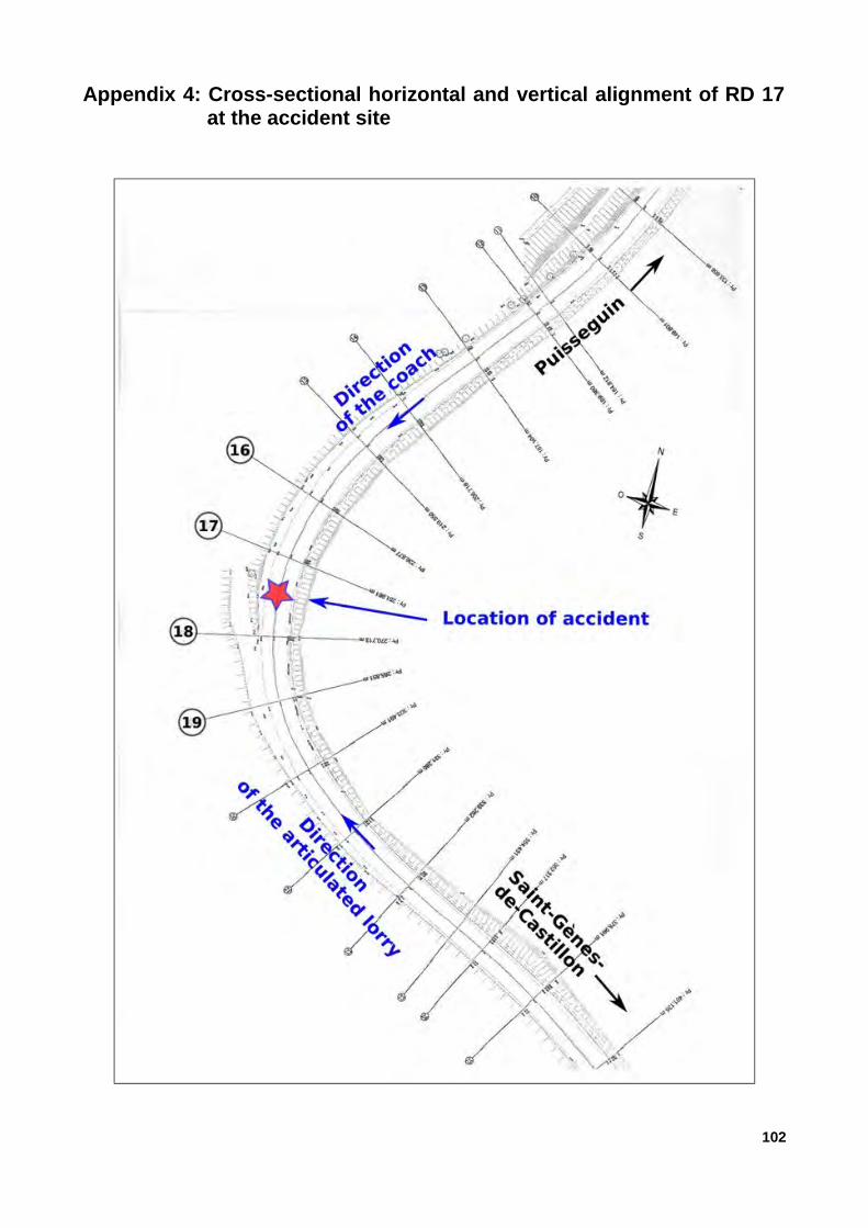
Appendix 4: Cross-sectional horizontal and vertical alignment of RD 17at the accident site
102

103

104

Appendix 5: Accident frequency rate on the RD 17 between 2010 and2015
105

Appendix 6: Description of the coach’s heating and air conditioningsystems
Heating
Figure 89 below shows schematically the various components of the heating system aswell as the routing of the ducts in which the heat transfer fluid circulates. Its key has beensimplified to make it easier to read.
The front part of the coach and the driver's compartment are heated by means of a heatexchange and blower unit installed at the front of the vehicle.
This unit, referred to as ”Front blower unit” in figure 89 is shown in an identical coach infigure 90 below.
106
(VA document annotated by the BEA-TT)
Figure 89: Schematic representation of the coach’s heating system

Air conditioning
The operation of the air conditioning system is based on the phase change of arefrigerant, the evaporation of which takes place with heat absorption and condensationwith heat production.
The air conditioning system includes:
➢ a compressor compressing the gaseous fluid, thereby increasing its pressure andtemperature;
➢ an exchanger/condenser where the gaseous fluid condenses and yields the heat thusproduced to the ambient air;
➢ a pressure reducer in which a reduction in the pressure of the refrigerant liquid takesplace;
➢ an evaporator exchanger in which the cooling of the refrigerant connected to itsevaporation is transmitted to the air.
According to the manufacturer, the maximum pressures of the refrigerant are in normaloperation (liquid state) at about 12 to 17 bars.
The minimum pressure in normal operation (gaseous state) is about 2 bar.
The pressures reached in the circuits depend on the ambient conditions and the level ofuse of the air conditioning.
Figure 91 below illustrates the operating principle of the coach’s air conditioning system.
107
(BEA-TT photo)
Figure 90: View of the front heat exchange and blower uniton a similar coach

The air conditioning system of the coach includes an air handling unit installed on the roofof the vehicle and an evaporator installed in the heat exchange and arc chute installed atthe front of the coach.
Figure 92 below shows schematically the air handling unit installed on the roof, theevaporator installed in the heat exchange and arc chute located at the front of the vehicle,and the flows and the different states of the refrigerant. Its key has been simplified tomake it easier to read.
108
Figure 91: Principle of operation of the air conditioning system
(VA document annotated by the BEA-TT)
Figure 92: Schematic representation of the coach’s air conditioning system
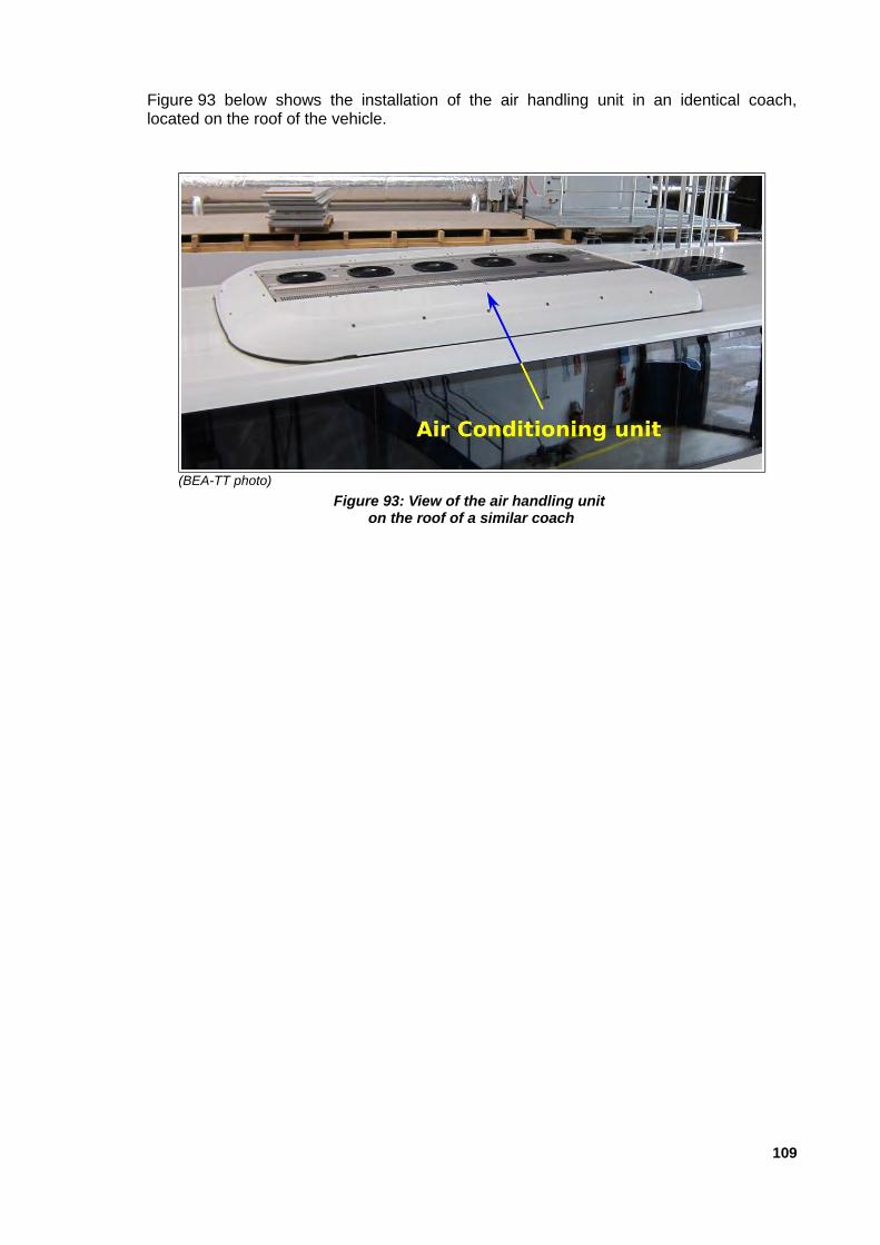
Figure 93 below shows the installation of the air handling unit in an identical coach,located on the roof of the vehicle.
109
(BEA-TT photo)
Figure 93: View of the air handling unit on the roof of a similar coach

Appendix 7: Extract from the safety data sheet for refrigerant R134a
110

Appendix 8: Extract from the safety data sheet for Glysantin G48
111

Appendix 9: Excerpts from the "TOTAL Diesel Premier" fuel safety datasheet
112

113
Appendix 10: Coach Passenger Safety Awareness Booklet published in2016 by the FNTV
114

115

116

117