report gunns limited - gunns pulp mill
TRANSCRIPT

Report
16B0104-E0035 rev D
December 16, 2005 January 17, 2006 rev A
March 30, 2006 rev B April 21, 2006 rev C
June 28, 2006 rev D
Gunns Limited
Bell Bay Pulp Mill Project, Tasmania
Pre-engineering Report for IIS

REV D 16B0104-E0035 1
Copyright © Jaakko Pöyry Oy
Copyright © Jaakko Pöyry Oy
All rights are reserved. This document or any part thereof may not be copied or reproduced without permission in writing from Jaakko Pöyry Oy

REV D 16B0104-E0035 i
Copyright © Jaakko Pöyry Oy
Summary
1. General Gunns objective of the project is to build a cost-effective, state-of-the-art, single-line pulp mill. The pulp mill capacity will initially be 820 000 ADt/a, but the capacity will expand to over 1 million tons per year once the mill is operating on 100 % plantation Eucalyptus and will eventually achieve 1.1 million ADt/a with gradual operational improvements and optimization. This document has been produced for the IIS in order to seek the approval for an annual production of 1.1 million ADt. The main raw material is eucalyptus however, for demonstration purposes, an estimated 100 000 ADt/annum of the production from Pinus radiata wood has been used in the study.
The pre-engineering was started in January 2005 and the main objectives of the work were:
− To develop the project concept by involving appropriate engineering and discussions with suppliers and to develop a cost estimate for the project.
− To develop the implementation plan for the project and to prepare time schedules for
the project.
− To define the best available production and environmental technology of the mill to comply with the “Emission Limit Guidelines” issued by the Tasmanian Resource Planning and Development Commission (RPDC) as well as with the BAT level environmental guidelines stipulated in the EU and North America based on the current state-of-the-art bleached kraft pulp mill technologies.
The target is to build the most cost-competitive large-scale pulp mill in the world, in accordance with the relevant environmental laws, regulations and guidelines. The following main objectives were set for the mill design:
− Full advantage will be taken of the effect of scale. The pulp mill will be designed for the highest possible capacity in a single-line operation.
− The pulp mill will represent state-of-the-art technology. The latest and best available
technology will be used in the design and the mill will be highly automated and efficient, with low maintenance costs.
− The mill will produce net sellable electricity and fully utilise forest biofuel to
generate electricity.
− The pulp mill is designed to comply with both the “Emission Limit Guidelines”, and with the BAT-level guidelines applied to new bleached kraft pulp mills in the EU and North America. The NOx emission limit, in JAAKKO PÖYRY’s opinion, needs to be reviewed and revised upwards in consideration that natural gas will be burnt in the lime kiln.

REV D 16B0104-E0035 ii
Copyright © Jaakko Pöyry Oy
The main report presents information and data about the processing of eucalyptus from forests and timber plantations. However, Gunns also proposes to use Pinus radiata as a wood raw material. While the implications of using Pinus radiata in the pulp mill are included in a separate report at Annex X, for ease of reference this Summary outlines the implications of processing both hardwood and softwood at the pulp mill.
2. Mill Site The existing chip mill site of Gunns Ltd. at Bell Bay was selected among several alternatives mainly because of several factors such as: location to the wood source, its proximity to the existing physical infrastructure and to the existing wood chip mill which would otherwise need to be constructed for the pulp mill.
The mill will be constructed on two large knolls about 1 km NNW of the existing Longreach chip mills. The total site area subject to site preparation works is about 70 ha. The ground level of the site where the main production departments of the pulp mill will be built is about + 62.5 m above mean sea level. The drying machine, pulp storage, chemical plant, and the effluent treatment plant will be constructed at somewhat lower elevations.
The selected location of the pulp mill requires rather extensive site levelling works and constructing parts of the mill at various levels. The cutting volume of soils and rock totals about 2.8 million m3. On the other hand, the cut and fill balance is rather favourable and no substantial off-site areas are needed for lay-down of extra soil masses.
The rock type in the area is Jurassic dolerite with soil covering of only 0.5–1.0 metres. The rock base will provide a good foundation base for the pulp mill construction and it is unlikely that any piling will be required.
3. Mill Concept
Mill Capacity The basic design concept for the pulp mill is as follows:
− The design capacity of the recovery boiler and recovery liquor circuit will ultimately dictate the mills capacity.
− In the first years of operation the raw material of the mill comprises primarily native eucalyptus. native eucalyptus has a lower cooking yield and a higher cooking chemical charge than plantation eucalyptus. At the design capacity of the cooking chemical recovery system the annual production is 820 000 ADt/a.
− In the later years when the production is utilising plantation the annual production will increase to 1 million ADt/a due to the higher cooking yield and lower cooking chemical charge per tonne of pulp.

REV D 16B0104-E0035 iii
Copyright © Jaakko Pöyry Oy
− With gradual operational improvements and optimization the production will increase to 1.1 million ADt/a when operating on 100 % plantation eucalyptus. Therefore the main machinery design is for a daily production capacity of 3492 ADt/d corresponding to 1.1 million ADt/annum at 100 % plantation eucalyptus raw material and 100 % eucalyptus pulp.
− The processing of Pinus radiata wood is also considered. For the study an estimated 100 000 ADt/annum has been used for demonstration purposes. The pine production can be expected to increase as more pine resources become available. When pine pulp is produced the total annual production will not reach 1.1 million ADt but will be approximately 1.05 million ADt.
All balances contained in this report, including calculations for effluent loads, atmospheric emissions, solid waste amounts, etc. have been based on the production capacity of 1.1 million ADt/a of BEKP (bleached eucalyptus kraft pulp). This document has been produced for the IIS in order to seek the approval for an annual production of 1.1 million ADt of bleached market kraft pulp. The final equipment selection, which may not be made until after the project has been approved, should only have a minor impact on the final balances and concepts described in this report. Under no circumstances would the environmental performance of the mill be worse than what is described in this document.
Department Design Capacities The mill department design capacities have been sized considering the different wood types processed: plantation eucalyptus, native eucalyptus, and Pinus radiata.
The daily design capacity on native eucalyptus equates to an annual production of 820 000 ADt/a.
The daily design capacity on 100 % plantation eucalyptus wood equates to an ultimate annual production of 1 100 000 ADt/a of 100 % eucalyptus pulp.
On Pinus radiata an average daily capacity of 2 043 ADt/d can be achieved.
To reach the target production for the various woods processed, the selected daily design values are shown below in Table 0-1.

REV D 16B0104-E0035 iv
Copyright © Jaakko Pöyry Oy
TABLE 0-1 Summary of Departmental Daily Design Capacities Plantation Euca Native Euca Pinus Radiata Maximum Design value Design value Design value Wood Handling - Chip screening m3l/h 1 850 1 531 1 802 Fibre Line - Cooking ADt/d 3 540 2 786 2 467 - Deknotting ADt/d 3 505 2 758 2 442 - Screening ADt/d 3 487 2 744 2 430 - O2 delignification ADt/d 3 417 2 689 2 357 - Bleaching ADt/d 3 315 2 608 2 274 - Drying ADt/d 3 492 2 756 2 321 Power and Recovery - Evaporation t H2O/h 1 200 1 075 1 098 - Recovery boiler (virgin solids)
t DS/d
4 100 4 116
4 096
- Recausticising m3 WL/d 10 000 9 718 9 338 - Lime kiln t lime/d 850 827 795 - Power Boiler kg/s 55 42 39 - Turboset MW 190 172 177 Chemical Plant - Chlorine dioxide plant t ClO2/d 50 40 39 - NaClO3 plant t NaClO3/d 200 (1) 73 72 - Hydochloric acid plant t HCl/d 100 86 69 - Chloralkali plant t NaOH/d 50 49 31 - O2 plant(1) t O2/d 200 (1) 72 80 (1) based on maximum merchant sodium chlorate of 140 t/d & merchant oxygen production of 110 t/d Water and Effluent Treatment - Water treatment plant m3/h 4 100 3 100 2 665 - Effluent treatment plant m3/h 3 720 2 770 2 415
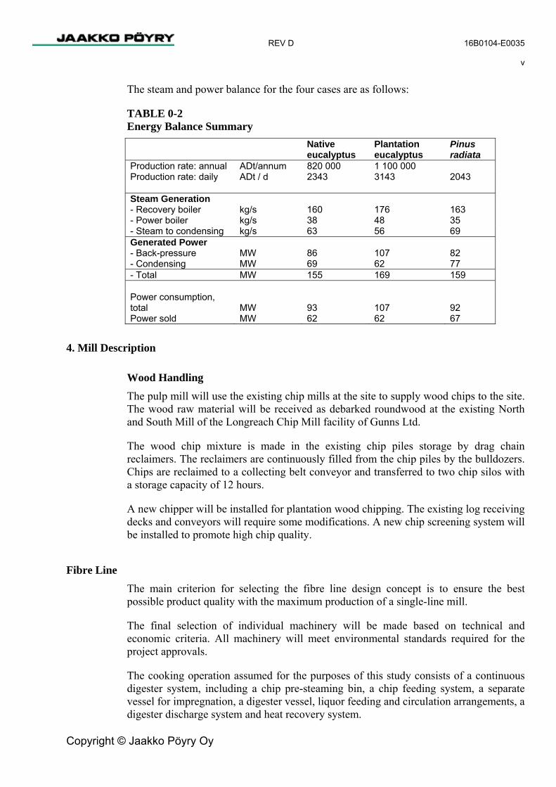
Energy Balances The energy balance depends on the production rate and the wood mixture that is being processed. The steam and power consumptions used in the energy balances are taken from the information received from the equipment vendors for the different pulp mill departments. The final selection of the vendors’ equipment will have an influence on the final data, but will not have any significant influence on the excess power that can be sold to the grid. However the real quantity of black liquor and its heat value can effect the steam generation and therefore also the power generation.
In the case of eucalyptus pulp, excess power of approximately 57 to 62 MW can be sold to the grid. In the case of processing Pinus radiata the value is approximately 67 MW. The main restriction in the steam and power generation when processing Pinus radiata and native eucalyptus is the capacity of the turbine condensing section, which is limited to approximately 70 kg/s.
REV D 16B0104-E0035 v
Copyright © Jaakko Pöyry Oy
The steam and power balance for the four cases are as follows:
TABLE 0-2 Energy Balance Summary Native
eucalyptus Plantation eucalyptus
Pinus radiata
Production rate: annual ADt/annum 820 000 1 100 000 Production rate: daily ADt / d 2343 3143 2043 Steam Generation - Recovery boiler - Power boiler
kg/s kg/s
160 38
176 48
163 35
- Steam to condensing kg/s 63 56 69 Generated Power - Back-pressure - Condensing
MW MW
86 69
107 62
82 77
- Total MW 155 169 159 Power consumption, total
MW
93
107
92
Power sold MW 62 62 67
4. Mill Description
Wood Handling The pulp mill will use the existing chip mills at the site to supply wood chips to the site. The wood raw material will be received as debarked roundwood at the existing North and South Mill of the Longreach Chip Mill facility of Gunns Ltd.
The wood chip mixture is made in the existing chip piles storage by drag chain reclaimers. The reclaimers are continuously filled from the chip piles by the bulldozers. Chips are reclaimed to a collecting belt conveyor and transferred to two chip silos with a storage capacity of 12 hours.
A new chipper will be installed for plantation wood chipping. The existing log receiving decks and conveyors will require some modifications. A new chip screening system will be installed to promote high chip quality.
Fibre Line The main criterion for selecting the fibre line design concept is to ensure the best possible product quality with the maximum production of a single-line mill.
The final selection of individual machinery will be made based on technical and economic criteria. All machinery will meet environmental standards required for the project approvals.
The cooking operation assumed for the purposes of this study consists of a continuous digester system, including a chip pre-steaming bin, a chip feeding system, a separate vessel for impregnation, a digester vessel, liquor feeding and circulation arrangements, a digester discharge system and heat recovery system.

REV D 16B0104-E0035 vi
Copyright © Jaakko Pöyry Oy
The screen room consists of knot separation, knot washing and knot returning system to the digester, pressurised screening in three stages and a reject dewatering system.
Brown stock washing takes place in the digester washing zone and in two washers in series. Washing can be by displacer drum or press drum types of washers.
Oxygen delignification consists of two pressurised oxygen reactors, a blow tank and white liquor oxidation system. Before bleaching, there are two washers in series with a brown stock storage tower between the washers.
Bleaching is carried out with a four-stage sequence D-EOP-D-D with the possibility to also use peroxide in the final stage. The first D stage will have the capability of operating with high temperature and under strong acid conditions. The final D stage will also be capable of operating as a peroxide stage. Pulp is washed after each bleaching reactor tower.
Drying Machine The bleached stock cleaning system consists of four-stage screening with slotted screens, followed by two-stage forward and two-stage reverse cleaning for both heavy and light reject removal.
The investment estimate is based on one twin-wire type machine, including a press section with two shoe presses, airborne pulp dryer, cutter layboy and three baling lines, The 250 kg bales are unitised into 2000 kg units.
All produced pulp will be transferred to the pulp warehouse. The warehouse for pulp storing and shipping is located about 1 500 m from the pulp mill.
Bleaching Chemicals Preparation Most of the bleaching chemicals will be manufactured at the mill with the remainder being imported.
The chemicals used in bleaching at the pulp mill will be:
− Sodium hydroxide − Oxygen − Chlorine dioxide − Hydrochloric acid − Sulphuric acid (under some operating scenarios) − Hydrogen peroxide − Sodium bisulphite
The sodium bisulphite will be produced in the NCG burning system.
For the chemical plant concept consideration has been made for the supply of bleaching chemicals to the pulp mill (designated as the Base Case – Integrated Chemical Plant) and also for the production of merchant chemicals (designated as the Merchant Chemical Plant Case).

REV D 16B0104-E0035 vii
Copyright © Jaakko Pöyry Oy
a. Base Case – Integrated Chemical Plant
As a basis for the environmental assessment and cost estimate of the mill, the
The following on-site production facilities are planned for the base case scenario:
− Alkali plant including brine preparation − Integrated chlorine dioxide plant consisting of
− Hydrochloric acid synthesis − Sodium chlorate electrolysis − Chlorine dioxide plant
− Oxygen plant
Under the base case scenario, the following main chemicals will need to be imported to site:
− Salt − Hydrogen peroxide − Caustic soda (additional to balance the pulp mill requirements) − Chemical plant filter aids, and flocculating agents − Sodium carbonate − Sulphuric acid (under some operating scenarios for pH control)
b. Merchant Chemical Plant Case
Gunns also seek approval for the manufacture of the following merchant chemicals:
− Sodium chlorate − Oxygen − Hydrogen peroxide
For the production of the merchant chemicals two different alternative chemical plant concepts have been considered.
Merchant Chemical Plant Case – Alternative 1
The Merchant Chemical Plant Alternative 1 concept has the same process as outlined for the Base Case – Integrated Chemical Plant for generating chlorine dioxide but with a larger production of sodium chlorate and oxygen. The extra portion of chlorate will require a chlorate crystallizing, drying, and bagging operations. Under this concept the merchant chemical products and merchant quantities are:
− Sodium chlorate (48 000 tonnes/annum) − Oxygen (49 000 tonnes/annum)

REV D 16B0104-E0035 viii
Copyright © Jaakko Pöyry Oy
Merchant Chemical Plant Case – Alternative 2
The Merchant Chemical Plant Alternative 2 uses the hydrogen peroxide and sulphuric acid based process for generating chlorine dioxide for the pulp mill bleaching. Alternative 2 considers the following on-site facilities:
− Brine preparation − Sodium chlorate electrolysis − Chlorine dioxide plant − Hydrogen peroxide plant − Oxygen plant
Under the alternative 2 concept, the merchant chemical products and merchant quantities are:
− Sodium chlorate (48 000 tonnes/annum) − Oxygen (35 000 tonnes/annum) − Hydrogen Peroxide (21 000 tonnes/annum)
Alternative 2 also requires a larger quantity of caustic soda and sulphuric acid to be imported compared to the base case.
Other minor chemicals, such as filter aids and sodium carbonate, are also required for the chemical plant, and will need to be imported for the options considered.
Evaporation The evaporation plant is proposed to consist of at least a seven-effect evaporation train, equipment for increasing the final dry solids content of firing liquor, a foul condensate stripper column and tank farm.
The reasons for selecting the process concept were two-fold. A seven effect system provides good steam economy and allows the production of more power from the generated steam. The second requirement is a high dry solid content of the firing liquor in order to minimise the emissions from the recovery boiler. The final concentration after the first six effects is carried out by three parallel concentrators.
Recovery Boiler The recovery boiler plant will consist of the recovery boiler with auxiliaries, an electrostatic precipitator, thermal feedwater treatment system, mill condensate treatment and chemical after-dosing systems.
The main criterion for selecting the particular recovery boiler design were its low sulphur, nitrogen oxides and particle emissions to the atmosphere and also higher steam parameters for high power generation.

REV D 16B0104-E0035 ix
Copyright © Jaakko Pöyry Oy
White Liquor Preparation The causticising plant will include raw green liquor storage, green liquor filtering and storage, dregs handling, lime slaking and recausticising, white liquor filtering using disc filters and storage, lime mud washing and filtering.
The lime kiln plant will consist of a lime kiln with flash dryer, auxiliaries, burner for natural gas (optionally for methanol), equipment for DNCG gas (collected from causticising area) incineration and an electrostatic precipitator.
Power Boiler The power boiler will be a fluidised bed combustion boiler (BFB) suitable for 100 % biofuel firing (fines from screening, sawdust, forest residues and dewatered primary effluent sludge).
The power boiler department comprises the combined bio-fuel, sludge and natural gas-fired boiler including auxiliary equipment like bio-fuel handling, ash silo with emptying device and electrostatic precipitator.
The power boiler will operate in parallel with the recovery boiler and generates HP (high pressure) steam at the same pressure and temperature. The power boiler will control the pressure of high-pressure steam.
Turbogenerator The power plant will feature one or two turbo-generator(s) with condensing tail and the necessary auxiliary facilities.
The turbine(s) will be furnished with the necessary number of uncontrolled bleeds for supply of soot-blowing steam at 32 bar(a), process steam at 12 bar(a) and 4 bar(a) pressure after the external control valves and the surplus steam is led to the condensing tail.
The plant will consist of by-pass stations to bypass the turbine from high-pressure steam net to 12 bar(a) and 4 bar(a) steam nets when the turbine is out of operation.
There will be a start-up and back-up power connection to the state electricity grid.
Water Supply Raw water is proposed to be pumped to the mill through a 35 km long pipeline from the existing Trevallyn Dam in the South Esk River.
The main unit operations in the treatment plant will be chemical mixing-flocculation-flotation clarification-rapid sand filtration- mill water basin -pumping.
Potable water - for use in offices, rest rooms, wash rooms and equal in the mill area - will be taken from the existing potable water supply.

REV D 16B0104-E0035 x
Copyright © Jaakko Pöyry Oy
Effluent Treatment The proposed effluent treatment plant comprises a modern primary and secondary effluent treatment facility. The secondary (biological) treatment features an extended aeration activated sludge process starting with an integrated anoxic chlorate removal stage and a two-stage selector part.
The treated effluent will be discharged to the ocean at Five Mile Bluff on the coast of Bass Strait through an effluent pipe provided with a multi-port diffuser system. The pipeline length will be about 23 km in length.
Electrification The plant power demand depends on the raw material being processed and the relative production rates. The power consumed by the mill and sold to the grid is shown in the following table.
TABLE 0-3 Mill Power Consumption Native
eucalyptus Plantation eucalyptus
Pinus radiata
Production rate: annual ADt/annum 820 000 1 100 000 Production rate: daily ADt / d 2343 3143 2043 Power consumption, total
MW
93
107
92
-Pulp mill MW 72 81 71 -Chemical plant MW 21 26 21 Power sold MW 62 62 67
A connection to the electricity grid will be established via a 220 kV switchyard.
The mill’s 33 kV medium-voltage distribution system will be connected to the 220 kV line via a three 63 MVA main transformers.
During normal operation, the generator will be more than capable of providing sufficient power to operate the mill. The surplus energy will be sold on the national electricity market.
Process Control The degree of automation will be in accordance with modern industrial practice. There will be several process control and mill systems:
− Distributed Control System (DCS) − Optimisation Packages (in DCS) for different process systems − Quality Control System (QCS) − Closed-Circuit TV System (CCTV) − Process Information Management System (PIMS) − Maintenance Management System (MMS) and Enterprise Resource Planning (ERP) − Programmable Logics (PLC) as integrated part of some machines.

REV D 16B0104-E0035 xi
Copyright © Jaakko Pöyry Oy
5. Environmental Consideration The general design objective of the environmental safeguards of the mill is to meet the Resource Planning and Development Commission (RPDC) emission limit guidelines contained in the document called “Recommended environmental emission limit guidelines for any new bleached eucalypt kraft pulp mill in Tasmania – Volume 2” (“Emission Limit Guidelines”). In addition, the BAT level international environmental standards and guidelines, like those promulgated by the European Union and the USEPA, will be complied with.
The compliance will be achieved with the mill design based on modern, proven production technology and on the choice of the mill equipment featuring the best possible environmental performance. This strategy, which combines the BAT level in-plant safeguards with the state-of-the-art external environmental protection measures, will result in the lowest possible environmental emissions of the mill.
The location of the mill may present special demands on its environmental performance. The detailed site suitability criteria and safeguards needed to mitigate any adverse impact will be assessed and defined in the IIS-process and taken fully into account in the subsequent implementation stages of the pulp mill.
Measures to effectively mitigate the fossil fuel derived greenhouse gas (GHG) emissions will be taken. The mill will produce an excess of renewable electricity to the grid and will be eligible for renewable energy credits (REC).
6. Project Implementation The purpose of the implementation plan described in Chapter 5 is to outline how the project will be developed. It briefly defines the main principles and criteria according to which project management, engineering, procurement, construction, check-out and initial operation with commissioning will be carried out. This implementation plan will have to be adjusted to the final project structure (e.g. Alliance)
The main target time schedule for the project is summarised below:
− Investment decision D− Start of procurement of main machinery D + 1 week− Start of excavation D + 1 week− Start of erection D + 8-9 months− Start of checkouts D + 19 months− First cooking (start of production) D + 26 months

REV D 16B0104-E0035 1
Copyright © Jaakko Pöyry Oy
Contents Preface Summary List of Abbreviations and Acronyms 6
1 INTRODUCTION AND PROJECT OVERVIEW 12
1.1 Background 12 1.2 Objectives of the Pre-engineering Study 12 1.3 Environmental Guidelines and Standards 13 1.3.1 Liquid Effluents 13 1.3.2 Gaseous Emissions 14 1.3.3 Other Environmental Stipulations 15
2 MILL SITE AND INFRASTRUCTURE 16
2.1 Site Location and Description 16 2.1.1 Site Selection 16 2.1.2 Bell Bay Site 17 2.1.3 Topography 17 2.1.4 General Geotechnical Conditions 17 2.1.5 Land Ownership and Classification 18 2.2 Description of Proposed General Layout 18 2.3 Geotechnical Investigations 19 2.4 Water Supply 20 2.5 Power Boiler Fuels 20 2.6 Effluent Treatment and Disposal 21 2.7 Power Connection 21 2.8 Transportation and Logistics 22 2.9 Socio-economic Infrastructure 22
3 MILL PROCESS AND TECHNOLOGY 24
3.1 Pulp Mill Design Principles 24 3.2 Product and Design Basis 24 3.3 Summary of Department Design Capacities 26 3.4 Department Design Criteria 27 3.5 Steam and Power Balances 31 3.5.1 General 31 3.5.2 Calculation Basis 31 3.5.3 Energy Balances 34 3.6 Water Balances 38 3.7 Consumption of Raw Materials 39 3.7.1 Wood Chip Consumption 39 3.7.2 Consumption of Chemicals 39 3.7.3 Consumption of Natural Gas 42

REV D 16B0104-E0035 2
Copyright © Jaakko Pöyry Oy
3.8 Description of Process Areas and Systems 43 3.8.1 Wood Handling 43 3.8.2 Fibre Line 45 3.8.3 Bleaching Chemical Preparation 58 3.8.4 Evaporation 72 3.8.5 Recovery Boiler 75 3.8.6 Recausticising 78 3.8.7 Lime Kiln 79 3.8.8 Turbogenerator 80 3.8.9 Power Boiler 81 3.8.10 Malodorous Gas Handling 82 3.8.11 Compressed Air Plant 84 3.8.12 Mill Water Treatment and Cooling Towers 84 3.8.13 Feedwater Treatment 87 3.8.14 Effluent Treatment Plant 88 3.8.15 Solid Waste Management 99 3.9 Electrical Systems 100 3.9.1 Power Distribution 100 3.9.2 Voltages 101 3.9.3 Electric Equipment 101 3.9.4 Lighting 103 3.10 Process Automation and Information Management 103 3.10.1 General 103 3.11 ERP (Enterprise Resource Planning) Concept 103 3.11.1 MES (Manufacturing Execution Systems) Concept 104 3.11.2 Field Automation 106 3.11.3 Networks 107 3.11.4 User Interface 107 3.11.5 Control Rooms 108 3.11.6 Storaging and Back-ups 109 3.11.7 Communications 109 3.12 Building Descriptions 110 3.13 HVAC Systems 110 3.13.1 Design Criteria 110 3.13.2 Ventilation Systems for Process Rooms 111 3.13.3 Air Conditioning Systems for Special Rooms 111 3.13.4 Heating System 112
4 ENVIRONMENTAL CONSIDERATIONS 113
4.1 Emission Control Strategy 113 4.2 Environmental Safeguards by Department 113 4.3 Water Supply 127 4.4 Effluent Treatment and Disposal 127 4.4.1 Compliance with the “Emission Limit Guidelines”, the EU/IPPC, and Other International Guidelines 127 4.5 Air Pollution Control 128 4.5.1 Gaseous Emission Safeguards 128 4.6 Solid Waste Handling 131 4.7 Noise Abatement 132

REV D 16B0104-E0035 3
Copyright © Jaakko Pöyry Oy
4.8 Mitigation of Environmental Risks 132 4.8.1 Preliminary Risk Identification 132 4.8.2 Prevention, Containment, and Recovery of Fibre, Black Liquor and other Hazardous Spills 136
5 PROJECT IMPLEMENTATION PLAN 138
5.1 Implementation Concept 138 5.2 Project Preparation 139 5.3 Assessment and Project Decision 139 5.4 Implementation 139 5.4.1 Project Organisation and Structure 139 5.4.2 Project Planning and Scheduling 143 5.4.3 Contracting and Procurement 145 5.5 Construction 148 5.5.1 General 148 5.5.2 Pre-construction Activities 148 5.5.3 Site Management 149 5.5.4 Quality Assurance Plan, Inspections 149 5.5.5 Site Engineering 149 5.5.6 Safety and Security 150 5.5.7 Mill Site Services 151 5.5.8 Civil Works 151 5.5.9 MEI Erection 152 5.5.10 Main Process Equipment Erection 153 5.5.11 Approvals by Local Authorities 153 5.5.12 Quality Assurance 153 5.5.13 Security/Safety and Environmental Issues 153 5.6 Cost Management 154 5.6.1 Project Budget 154 5.6.2 Cost Engineering and Control 154 5.7 Engineering 154 5.7.1 Project Standards 154 5.7.2 Safety Marking 154 5.7.3 Approvals by Local Authorities 154 5.7.4 Quality Assurance 155 5.7.5 Detailed Engineering 155 5.8 Documentation and Information Management 155 5.8.1 General 156 5.8.2 Document Management 157 5.9 Preparation for Start-up 158 5.9.1 Check-out 159 5.9.2 Test Runs 159 5.9.3 Take-over 159 5.10 Preparations for Operations 160 5.10.1 Manning and Organisation 160 5.10.2 Material and Service Contract Management 161 5.10.3 Maintenance Policy 161 5.10.4 Quality Management 161

REV D 16B0104-E0035 4
Copyright © Jaakko Pöyry Oy
Annexes I Pulp Mill Main Dimensioning II Energy Balances 16B0104-E0003 III Mill-wide Water Balances IV Overall Material Balance V Effluent Load and Treatment Plant Design VI Gaseous Emissions 16B0104-10005 VII Solid Waste Amounts VIII Environmental Emission Diagram IX Mill Wide Tank List X Pinus Radiata Production 16B0104-E0021 XI Typical Noise Emissions of a Modern Bleached Kraft Pulp Mill 16B0104-10004 XII Building Description 16B104-E0008 XIII Space Requirements for Non-process (Auxiliary) Facilities 16B0104-E0009 XIV Design Criteria and Description of HVAC Systems 16B0104-E0018 XV Special Studies 16B0104-E0002 Alcell Solvent Pulping 16B0104-E0005 Fuels for the Power Boiler 16B0104-E0010 Excavation and Filling Analysis 16B0104-E0012 Pulp Warehousing and Loading 16B0104-E0014 NOx Issues 16B0104-E0040 Assessment and Selection of the Pulp Bleaching Process 16B0104-E0041 Integrated Chemical Plant discussion report 16B0104-O0002 Mill Manning Plan XVI Mill Site Location and Description XVII Preliminary Start-up Schedule (16B0104-T0010)

REV D 16B0104-E0035 5
Copyright © Jaakko Pöyry Oy
DRAWINGS: Line Diagrams Stormwater Treatment 16B0104-02025 Effluent Treatment 16B0104-02026 Odorous Gas Handling 16B0104-02027 MeOH Liquefaction-Turpentine 16B0104-02030 Effluent pipe 16B0104-02031 Process Orientation Diagram 16B0104-02034 Process Orientation Diagram Integrated Chemical Plant 16B0104-02035 Spill Collection Pulp Mill 16B0104-02036 Merchant Based Chemical Plant, Alternative 1 16B0104-02043 Merchant Based Chemical Plant, Alternative 2 16B0104-02040 Mill Site Layouts Bell Bay Site Mill Site Location Map 16B0104-10001 Bell Bay Site 16B0104-10002 Underground Process Sewers 16B0104-10057 Preliminary Sketches Photo Montages Day A 3112 Day B 3147 Day C 5926 Day D 5943 Night A 3112 Night B Night C Night D Principal Elevations 16B0104-30003

REV D 16B0104-E0035 6
Copyright © Jaakko Pöyry Oy
LIST OF ABBREVIATIONS AND ACRONYMS
A a annum A acid stage in bleaching, area AA active alkali, AA=NaOH+Na2S ADt air (90%) dry ton ADtbl air (90%) dry ton, bleached Al aluminium Al2(SO4)3 aluminium sulphate (alum) ANZECC Australian and New Zealand environment and conservation council AOX adsorbable organic halides, SCAN-W 9:89 AQ anthraquinone AUD Australian dollar B bar(a) pressure (absolute) bar(g) pressure (gauge) BAT best available technique BDt bone (100 %) dry ton BDS bone dry solids BDU bone dry unit BEK bleached eucalyptus kraft BEKP bleached eucalyptus kraft pulp BFB bubbling fluidized bed combustion boiler BHKP bleached hardwood kraft pulp BL black liquor BoP balance of plant BOD5 biological oxygen demand, five day test, SCAN-W 5:71 BPR boiling point rise BSKP bleached softwood kraft pulp C C chlorination stage in bleaching, carbon, concentration CaCO3 calcium carbonate (lime stone) Ca(HSO3)2 calcium bisulphite CaO calcium oxide (burnt lime) Ca(OH)2 calcium hydroxide CCT corrugated crush test (edgewise compression strength measurement) CCTV closed-circuit TV system CE CE marking (product meets the requirements of all relevant European Directives) Cl2 chlorine (gas) ClO2 chlorine dioxide (gas) CNCG concentrated non-condensable gases CO carbon monoxide CO2 carbon dioxide CO3 carbonate COD chemical oxygen demand

REV D 16B0104-E0035 7
Copyright © Jaakko Pöyry Oy
CO(NH2)2 urea D d day(s) D chlorine dioxide stage in bleaching D0 first chlorine dioxide stage in bleaching D1 second chlorine dioxide stage in bleaching D2 third chlorine dioxide stage in bleaching dB decibel DCS distributed control system, data collection system DD drum displacement (washer), double disc (refiner) DF dilution factor dia diameter dm3 cubic decimetre DMS dimethyl sulphide, document management system DN diameter nominal (pipes) DNCG diluted non-condensable gases DR displacement ratio DS dry solid, dissolved solid, degree of substitution E E alkaline extraction stage in bleaching, E-value (washing efficiency) EA effective alkali, EA=NaOH+1/2Na2S EC50 median effective concentration (required to induce a 50% effect) ECF elemental chlorine free EDD electronic device description EDTA ethylenediaminetetraacetic acid EOP oxygen and peroxide enhanced alkali extraction stage in bleaching ERP enterprise resource planning ESP electrostatic precipitator EU European union F FW feed water G g gram GHG greenhouse gas emission GIS gas insulated switchgear GJ giga joule Gl giga litre GL green liquor H h hour, height HBL hot black liquor HC high consistency HCl hydrochloric acid HD high density HERB high energy recovery boiler HRT Hydraulic Retention Time

REV D 16B0104-E0035 8
Copyright © Jaakko Pöyry Oy
HNO3 nitric acid H2O2 hydrogen peroxide HP high pressure (steam), horse power H3PO4 phosphoric acid H2S hydrogen sulfide H2SO4 sulphuric acid HVAC heating, ventilation and air conditioning HVLC high volume, low concentration (diluted odorous gases) HW hardwood HWL hot white liquor Hz hertz I ID induced-draft (fan) IIS integrated impact statement I/O input/output IPPC integrated pollution prevention control I iodine ISO international standard organisation, http://www.iso.org J JP Jaakko Pöyry company K K potassium, kelvin Kappa number Measure of the amount of lignin remaining in pulp after cooking. In addition to
lignin, some other components like hexen uronic acids affect kappa number KCl potassium chloride kg kilogram KMnO4 potassium permanganate kV kilovolt kWh kilowatt hour L l litre (L) LC low consistency LC50 Lethal concentration 50 (concentration in water having 50 % chance of causing
death to aquatic life) LHV recovery boiler efficiency, low heating (heat) value LP low pressure (steam, ~ 4 bar) L/W liquor-to-wood ratio M m meter max maximum m2 square meter m3 cubic meter m3l cubic meter loose m3sob cubic meter solid over bark m3sub cubic meter solid under bark MBB moving biological bed technology (reactor)

REV D 16B0104-E0035 9
Copyright © Jaakko Pöyry Oy
MC medium consistency, moisture content MCC motor control center, modified continuous cooking MCR maximum continuous rating (load) MeOH methanol MEI mechanical, electrical and instrumentation MES manufacturing execution system MF machine finished MG machine glazed mg milligram Mg(HSO3)2 magnesium bisulphite MgO magnesium oxide MgSO3 magnesium sulphite MgSO4 magnesium sulphate min minimum, minute MJ mega joule MLVSS mixed liquor volatile suspended solids MMS maintenance management system Mn manganese MnO manganese oxide MP medium pressure (steam, ~ 12 bar) MPa mega Pascal (pressure) mS milli Siemens MVA mega volt ampere MVR mechanical vapour recompression MW megawatt MWC medium weight coated (paper) MWWB Mill wide water balance N NaCl sodium chloride NaClO3 sodium chlorate NaCO3 sodium carbonate NaHSO3 sodium bisulphite Na2O sodium oxide NaOH sodium hydroxide Na2SO3 sodium sulphite Na2SO4 sodium sulphate Na2S sodium sulphide Na2S2O3 sodium thiosulphate Na2S2O4 hydrosulphite (dithionite) NCG noncondensable gases NE north east NH2SO3H sulphamic acid (NH4)HSO3 ammonium bisulphite (NH4)2SO3 ammonium sulphite NNW north-northwest Nm3 normal cubic meter (gases) NOEC No observed effect concentration

REV D 16B0104-E0035 10
Copyright © Jaakko Pöyry Oy
Nox nitrogen oxides NTU nephlometric turbidity unit O O oxygen delignification stage O2 oxygen O3 ozone OD oven (100 %) dry OHBC open hatch bulk carriers OMB overall mill balance P P peroxide stage in bleaching, phosphorus pH Potential of Hydrogen - negative 10-base log (power) of the positive hydrogen
ion concentration; measure of acidity Paa peracetic acid pg Picogram (one-trillionth of a gram) PIMS process information management system PLC programmable logic controller POSS project of state significance Ppmm parts per million, mass basis Ppmv parts per million, volume basis Q Q chelating stage in bleaching, flow rate QAP quality assurance plan QCS quality control system QoS quality of service R RB recovery boiler REDOX Reduction oxidation REC renewable energy credits RMP rounds per minute RPDC resource planning and development commission (Australia) RPM revolutions per minute S s second, solid S sulphur SAN storage area network SCADA supervisory control and data acquisition SCAN Scandinavian Pulp, Paper & Board Testing Committee, standard SO2 sulphur dioxide SO4 sulphate SRC safety, rehabilitation and compensation SS suspended solids, stainless steel SW softwood, south west

REV D 16B0104-E0035 11
Copyright © Jaakko Pöyry Oy
T t ton (metric), time TA total alkali TAPPI Technical Association of Pulp and Paper Industry (USA), standard,
http://www.tappi.org TCF total chlorine free TCP/IP transmission control protocol/internet protocol TCDD tetrachlorodibenzodioxin TCDF tetrachlorodibenzofuran TDS total dissolved solids tpa tons per annum (TPA) tpd tons per day (TPD) tpy tons per year (TPY) TRS total reduced sulphur TSP total suspended particulates TSS total suspended solids U USEPA United States Environmental Protection Agency V V volt VOIP Voice over internet protocol VSD variable speed drive W W watt WAS waste activated sludge WBL weak black liquor WL white liquor Others °C celsius-degree % percent % ISO brightness of pulp, ISO 2410

REV D 16B0104-E0035 12
Copyright © Jaakko Pöyry Oy
1 INTRODUCTION AND PROJECT OVERVIEW
1.1 Background Gunns Limited plans to build a bleached hardwood and softwood kraft pulp mill at Bell Bay in northern Tasmania. The preferred resource for the mill will be plantation wood, but wood from native eucalyptus will also be used initially to make up the mill’s capacity targets. The annual capacity target is 820 000 ADt of bleached and baled pulp at the projected wood mixture in the year 2008. The capacity will expand to over 1 million tons per year once the mill is operating on 100 % plantation wood and will eventually achieve 1.1 million ADt/a with gradual operational improvements and optimization. All balances contained in this report, except for reasons otherwise stated, including calculations for effluent loads, atmospheric emissions, solid waste amounts, etc. have been based on the production capacity of 1.1 million ADt/a. This document has been produced for the IIS in order to seek the approval for an annual production of 1.1 million ADt. The main raw material is eucalyptus however, for the study demonstration purposes, an estimated 100 000 ADt/annum of the production has been considered to be from Pinus radiata wood. The pine production can be expected to increase as more pine resources become available. The final equipment selection, which will not be made until after the project has been approved, should only have a minor impact on the final balances and concepts described in this report.
The mill would be integrated with the company’s existing wood chip mill and a new wharf facility would be built to the site.
The pre-engineering phase has been carried out in order to supply the necessary support and input to the Integrated Impact Statement (IIS) work carried out by GHD. The IIS will assess the environmental, economic and social impacts of the project.
1.2 Objectives of the Pre-engineering Study The pre-engineering phase has focussed on the definition and dimensioning of the main processes with respect to the environmental considerations, and developing the site layout and preliminary department layouts No binding offers of equipment have been requested at this stage, but a series of meetings with potential and, from the conceptual point of view, the most important equipment suppliers has been held in order to select the optimal technology concept, in terms of environmental constraints, as the working hypothesis for the development of the mill processes and layouts.
Based on this work, JAAKKO PÖYRY can provide the IIS consultant with the necessary technical information for the preparation of the IIS report as required in the Resource Planning and Development Commission (RPDC) Guidelines (“IIS Guidelines”), which define the procedures to obtain the required approvals for the project to proceed. The permitting process of the mill will follow the “Project of State Significance” (POSS) procedures.

REV D 16B0104-E0035 13
Copyright © Jaakko Pöyry Oy
Consequently, the main objectives of the pre-engineering work are:
− More detailed development of the project concept, involving appropriate engineering and discussions with suppliers to make a further developed investment cost estimate and preliminary project budget for the project.
− Project planning to develop the implementation plan and prepare detailed time schedules for the project.
− Definition of the best available production and environmental technology of the mill to comply with the “Emission Limit Guidelines” issued by the Tasmanian Resource Planning and Development Commission (RPDC) as well as with the BAT level environmental guidelines stipulated in the EU and North America based on the current state-of-the-art bleached kraft pulp mill technologies.
1.3 Environmental Guidelines and Standards
1.3.1 Liquid Effluents In October 2004, the Tasmanian government adopted the “Recommended Environmental Emission Limit Guidelines for any New Bleached Eucalypt Kraft Pulp Mill in Tasmania – Volume 2” prepared by the RPDC (“Emission Limit Guidelines”). The “Emission Limit Guidelines” provide a detailed environmental management and technology framework for any new pulp mill project to be considered in Tasmania, were adopted by the Tasmanian government.
According to the “Emission Limit Guidelines” the final effluent limits for any new pulp mill in Tasmania discharging to the marine environment are as follows:
TABLE 1-1 Final Effluent Limits
BOD5
kg/ADt COD(Cr) kg/ADt
TSS kg/ADt
AOX kg/ADt
Colour kg/ADt
Monthly average 2.1 20 2.6 0.2 42 Daily maximum 3.6 34 4.5 0.4 72
The limits are valid for mills using both ECF and TCF bleaching processes, except for AOX, which applies only to the ECF mills, since the AOX load from TCF bleaching is, by definition, non-detectable.
The “Emission Limit Guidelines” also stipulate limits for acute (LC50/EC50) and chronic (EC50) toxicity, 2,3,7, 8-TCDD, 2,3,7,8-TCDF, chlorate, and trihalomethanes in the final effluent. The limits are as follows:
− Acute toxicity, LC50/EC50 a)
− Chronic toxicity, EC50 b) − 2,3,7,8-TCDD, pg/l 10 − 2,3,7,8-TCDF, pg/l 30 − Chlorate, mg/l 10 − Trihalomethanes, incl. chloroform, mg/l 2 − Oil and Grease No visible contamination

REV D 16B0104-E0035 14
Copyright © Jaakko Pöyry Oy
a) Acute toxicity should be measured in 100 % effluent. The effect from the effluent should be less than 50 %.
b) Chronic toxicity should be measured in effluent at various dilutions above and below the dilution
expected at the edge of the mixing zone. The concentration at which a 50 % effect is obtained should be determined. The Lowest Observed Effect Concentration (LOEC) and the No Observed Effect Concentration (NOEC) should also bedetermined. The discharge limit will be set such that the NOEC is not exceeded at the edge of the mixing zone.
As described below, all the limits listed above can be met with the Best Available Technology (BAT) environmental safeguards already in use in, bleached kraft pulp mills.
In addition to the “Emission Limit Guidelines”, the final effluent of the mill must be assessed against the requirements contained the Australia and New Zealand Environmental Coordination Committee (ANZECC) Guidelines, which list the maximum allowable ambient concentrations for about 200 hazardous chemicals in the marine environment. An analysis of final effluent loads and their consistency with the ANZECC Guidelines is presented in the IIS report based on the liquid effluent loads given in this document.
1.3.2 Gaseous Emissions The gaseous emission limits stipulated in the “Emission Limit Guidelines” for the recovery boiler, power boiler, lime kiln flue gases, NCG incinerator, bleach plant and chemical plant are as follows:
TABLE 1-2 Gaseous Emissions
Recovery Boiler (mg/Nm3, (3% O2, 273 K, dry, 101.3 kPa) TSP (total suspended particulates) 50 SO2 see below TRS (total reduced sulphur as H2S) 7 (> 99% of time) NOx see below PCDD/PCDF (as ng/Nm3) 0.1 Power Boiler (mg/N m3, (8% O2, 273 K, dry, 101.3 kPa)) TSP 30 SO2 see below NOx 80 mg NO2/MJ fuel input PCDD/PCDF (as ng/Nm3) 0.1 Lime Kiln (mg/N m3 (same as RB)) TSP 40 SO2 see below NOx see below TRS (as H2S) 16 PCDD/PCDF (as ng/Nm3) 0.1

REV D 16B0104-E0035 15
Copyright © Jaakko Pöyry Oy
NCG Incinerator (mg/N m3 (same as RB)) TRS (as H2S) 7 NOx see below SO2 see below SO2 (from all sources, annual avg.) kg S/ADt 0.4 NOx (from all sources, except for power boiler, annual avg.) kg NO2/ADt 1.3 Chlorine compounds (HCl, etc., all sources) mg Cl/N m3 50
The power boiler SO2 and NOx limit are recorded separately from the mill-wide sources. The above emission limits are achievable in modern BAT-level mills, except for the NOx limit of 1.3 kg NO2/ADt (process sources), which is likely difficult to achieve. Recent experiences with the mills in Scandinavia suggest that limits of about 1.5-1.6 kg NO2/ADt are achieveable. A separate report “16B01040-E0014 NOx Issues” is contained at Annex XV and considers NOx emissions in greater detail. Measures to mitigate NOx emissions are also outlined in the IIS. The mill could meet the NOx emissions depending on the fuel used. The additional mitigation measures would, however, mean that heavy fuel oil is required to be burnt in the lime kiln instead of natural gas as proposed since the nitrogen content of fuel oil is significantly lower than natural gas.
The guidelines stipulate a strict, 3-minute average ground level concentration for TRS outside the mill property limit. The figure is 1.4 micrograms H2S/m3 of ambient air, which is about the same as the lowest reported odour threshold of H2S.
1.3.3 Other Environmental Stipulations Other environmental stipulations developed in the “Emission Limit Guidelines” focus on solid waste disposal and environmental noise guidelines. The “Emission Limit Guidelines” are typical to all modern BAT-level mills and they can be complied with.

REV D 16B0104-E0035 16
Copyright © Jaakko Pöyry Oy
2 MILL SITE AND INFRASTRUCTURE
2.1 Site Location and Description
2.1.1 Site Selection In the pre-feasibility stage of the pulp mill project several sites across northern Tasmania were considered. After the subsequent screening the existing chip mill sites of Gunns Ltd. at Bell Bay and Hampshire were shortlisted.
These sites feature many advantages over other sites in northern Tasmania in terms of proximity to the wood resource and to the existing physical infrastructure, like roads, rail, power, gas, and wharf connections and to the existing wood chip mills, which otherwise would have to be constructed for the pulp mill.
From the water supply and environmental point of view the two sites would require relatively high initial investments, but these are manageable issues and no fatal flaws in this respect can be identified.
While a more detailed assessment of the two sites and their relative benefits and constraints will be provided in the IIS, for the purpose of this report it is sufficient to note that Gunns’ assessment was that the Bell Bay Location would be a better option due to:
− A more central location in terms of wood supply resulting in substantial savings in transportation cost of wood
− A larger, existing wood chipping capacity − Better highway connections − The site has its own wharf − A rail line runs next to the site − HV-power lines run next to the site − The main natural gas pipeline runs next to the site − More secure fresh water supply − Shorter effluent pipeline to the sea − Proximity to the large Bell Bay industrial estate
On the other hand, it was concluded that the existing environmental conditions around Bell Bay site may be vulnerable to the noise and gaseous emissions of the mill, unless appropriate safeguards are taken. Therefore in addition to necessary safeguards to comply with the “Emission Limit Guidelines”, special measures should be implemented at extra cost to control the noise emissions and to conserve the ambient air quality in the surroundings of the site, especially in the rural communities of Rowella and Kayena across the Tamar River. These special measures are addressed in the IIS by GHD.

REV D 16B0104-E0035 17
Copyright © Jaakko Pöyry Oy
2.1.2 Bell Bay Site The detailed location of the mill site is presented in Annex XVI; Mill Site Location and Description. The distances of the site to Launceston, George Town, and Bell Bay Port are about 30 km, 12 km and 8 km, respectively.
The mill will be constructed on two hills, which will be levelled to the required height, about 1 km NNW of the existing Longreach chip mills. The site area subject to site preparation works totals approximately 70 ha. The ground level of the site where the main production departments of the pulp mill will be built is about + 62.5 m above mean sea level. The drying machine, pulp storage, chemical plant, and the effluent treatment plant will be constructed at somewhat lower elevations (see Item 2.2).
The A8 Launceston-George Town highway is about 1 km, the gas pipeline about 0.8 km, the railway line about 0.5 km and the power lines about 0.1 km NE of the site.
Sufficient land area is available to build the production lines of a potential second pulp mill at the same site, although this requires the relocation of the existing power lines. In addition, more land is available on the SW side of the A8 highway to build integrated paper machines in the future.
2.1.3 Topography The selected location on a large knoll in a generally hilly landscape requires site levelling works and the construction of parts of the mill at differing levels. The total cutting volume of soils and rock is about 2.7 million m3. On the other hand, the cut and fill balance is rather favourable and no substantial off-site areas are needed for lay-down of extra soil masses. The final elevations and earth moving quantities of the various departments are subject to detail engineering.
The significant geographic separation and elevation difference between the existing chip mill and the pulp mill (about 50 m) requires the construction of a 1.5 km long chip conveyor. In addition, a new pulp export wharf and a pulp warehouse must be built about 1.5 km NW of the pulp mill and south of Big Bay.
2.1.4 General Geotechnical Conditions The rock type at the site is Jurassic dolerite with a soil covering 0.5-1.0 metres. The rock base provides good geotechnical foundation conditions for the mill. It is unlikely that any substantial piling is required. However, the extensive site levelling works will require substantial drilling and blasting, as well as soils and rock moving at the site.
A more detailed description of the geotechnical issues is presented below in Item 2.3.

REV D 16B0104-E0035 18
Copyright © Jaakko Pöyry Oy
2.1.5 Land Ownership and Classification The landowner of the site is currently Comalco, which has agreed, in principle, to sell the land to Gunns Ltd.
2.2 Description of Proposed General Layout The main objectives of the Mill Layout are:
− The chip mill operations remain as they are. − For the pulp mill there will be an access road branching off from the chip mill access
road. For the construction phase a temporary access road would need to be opened. − The internal logistics will be planned for a minimum amount of crossing traffic
within the mill site, especially for the major transport items like biofuel, salt and pulp.
− The general layout will be a compact footprint type of layout, where the interconnections are optimally minimised.
− For the construction of the mill the power lines will be retained. − The mill will be located as close as possible to the power lines and construction area
and as far away from the river as possible. − The area close to the river bank will be kept untouched and earth moving volumes to
hillside will be limited.
With the above statements as a basis, several alternatives were tested and prepared. In Drawings 16B0104-10001, 16B0104-10002 and in Photo Montages. The mill is located on the site area so that:
− The cut and balance has been minimised and there is space at the site to place the removed top soil. To optimise excavation work, the levels have been preliminary selected as follows (see also Annex XV; 16B0104-E0010: Excavation and Filling Analysis):
− pulp mill, recovery island and main office are on level +62.5 metres − drying machines, raw water treatment and work shop are on level + 57.5metres − substation is on level + 51 metres − chemical plant and effluent treatment are on level + 24.5 to + 30.5 metres − pulp warehouse and wharf are on level +5 metres.
− There will be enough material at the site left to cut for the expansion fill and construction material. The hill top in the southern end of the site has been left untouched.
− The mill site is enclosed. − The main traffic runs from south to north. All traffic to the site goes through the
main gate. After the gate personnel traffic and heavy deliveries of raw materials traffic are separated. Next to the gate house is the parking lot for personnel and visitors. Another personnel parking lot is located close to the work shop.
− The main office and the control room are centralised between the pulp mill and the recovery island. There is a parking area for visitors and management purposes.
− The work shop is centrally located at the mill.

REV D 16B0104-E0035 19
Copyright © Jaakko Pöyry Oy
− The process piping connections needed between departments are located in interconnecting pipe bridges.
− The 220 kV switch yard and natural gas reduction station are located north of the drying machines. There will be a new 220 kV power line from the Bell Bay switch yard to the mill site, see Chapter 2.7: Power Connection. In the location of the NG reduction station needed safety distances are considered.
− The effluent treatment plant is situated on the northern side of the mill site because of the ground profile. The chemical plant is located in the same area.
− A new wharf and pulp storage next to the wharf have been included. The wharf is located in the northernmost part of the site to avoid contamination of pulp bales with wood dust.
− To the east side of the power lines there is 10 ha area reserved for precast fabrication, batching plant and construction material storages.
2.3 Geotechnical Investigations The results of the geotechnical investigations conducted between 10th February and 9th March, 2005 are described in a separate report prepared by BFP Consultants Pty Ltd, April-05, Job No 2305089.
The conclusions and recommendations of the report are summarised in the following (extracts of the report, Chapter 6.0):
“Given the variability of subsurface materials and weathering across the site, it is difficult to accurately quantify the entire site in terms of ease of excavation.
However, it is a conservative estimate that up to 10 metres of weathered overburden, consisting of extremely weathered to highly weathered dolerite rock, may be excavated from the central area of the proposed main building area, at RL 70 and above.
Beyond this depth, it is likely that rock-breaking and explosive techniques would be required to remove slightly weathered to fresh rock for the specified founding levels to be realized. Weathering along joint and fracture surfaces would allow some excavation of more competent material whereby large ‘blocks’ of rock could be removed by use of a large excavator.
Excavated overburden and rock may be used as clean fill material, if required. Similarly, suitably crushed rock could be utilized for a multitude of other engineering purposes, including drainage gravel, road base and concrete aggregate. Although the fresh dolerite rock appears visibly suitable for such purposes, further clarification and testing procedures would be required to determine the suitability of such materials.
An allowable bearing pressure of 1500 kPa would be available for shallow footings founded to the silty clay material. Similarly, an allowable bearing pressure of 700 kPa would be available for structures founded to the highly to moderately weathered Jurassic dolerite rock.
For bored piers and pad footings founded to slightly weathered to fresh rock dolerite rock, an allowable end bearing pressure of 5MPa would be available.

REV D 16B0104-E0035 20
Copyright © Jaakko Pöyry Oy
Based on the information provided by the client with regard to anticipated foundation levels, it is unlikely that foundation excavations would intersect groundwater. However, there is some possibility that excavations on steeper parts of the site, where the piezometer surface appears to be significantly closer to the topographic surface, may encounter groundwater ingress at a relatively shallow depth.
The base of all footing excavations should be inspected to ensure that the founding medium meets the requirements referenced herein with respect to type and strength of founding material.”
The mill site layout and the excavation and filling plan have been prepared based on the above described geotechnical investigation. Geotechnical investigation of the site will continue in the detailed design and engineering phase of the project.
2.4 Water Supply Trevallyn Dam. A new pumping station would need to be built next to the existing hydropower station and the water would be pumped in a 35 km long pipeline to the mill site. While the design fresh water demand for the proposed pulp mill is about 26 Gl/a, the ultimate target water demand is about 40 Gl/a to allow for future expansion.
The technical details of the above system are described in a special report prepared by GHD.
2.5 Power Boiler Fuels The power boiler will use biofuel to produce steam for energy generation. The power boiler biofuel availability, properties and cost are described in more detail in “16B0104-E0005 Fuels for the Power Boiler”. The report is enclosed as part of Annex XV. The availability of different fuels is shown in Table 2-1. The pulp mill produces primary and secondary sludge at the effluent treatment plant. In fibre line operations some screening rejects are produced. As forest debarking will be used, no bark will come with the wood to the mill. The fines unsuitable for pulping produced in chip screening will be burned. Sawmills and other Gunns operations will produce wood residues that can be burned.
The yearly amount of sawdust and residues has been confirmed with Gunns. The amount of 200 000 kg(wet)/a of forest residues is the first estimate based on the availability of extra biofuel in the vicinity of the Bell Bay pulp mill site. An additional amount of 100 000 kg(wet)/a of forest residues was confirmed to be available, albeit at slightly higher cost. The amounts of primary sludge, rejects and fines are based on specific flows at similar mills in the JAAKKO PÖYRY database. Log residues are included in the screening flow.

REV D 16B0104-E0035 21
Copyright © Jaakko Pöyry Oy
TABLE 2-1 Availability of Biofuels for Gunns
Fuels m3/a ton(dry)/a ton(wet)/a
GJ/ton (wet)
GJ/a
Primary sludge 50 000 16 400 36 500 5.8 212 000Screening washing/knotting reject (eucalyptus wood) 21 000 4 100
12 000 4.8 58 000
Bark (eucalyptus wood) 0 0 0 6.0 0Fines from screening (eucalyptus) 144 000 31 900 72 000 7.1 508 000Sawdust and residues (eucalyptus)
264 000 64 800 132 000 7.8 1 028 000
Forest residues (eucalyptus) 364 000 110 600 200 000 9.2 1 838 000Forest residues (eucalyptus), add. 182 000 55 300 100 000 9.2 919 000Total 1 025 000 283 000 552 500 4 563 000
The total flow corresponds to an average wet fuel flow of 17.6 kg/s to the power boiler.
2.6 Effluent Treatment and Disposal The effluent discharged from the site is a combination of biologically treated process effluent, biologically treated sanitary sewage and clean storm water, and if it is contaminated, treated storm water. The raw effluents will originate from both the new pulp mill area and the existing chip mill area.
As described in 3.8.14 below, the process effluents will be cleaned at the site in a state-of-the-art effluent treatment plant featuring both primary and secondary treatment systems. The final effluent quality will comply with the “Emission Limit Guidelines”
The sanitary sewage from the mill site will be collected into a dedicated sewage system provided with septic tanks to separate floating and settling solids. The settled sewage will be combined with the process effluent at the secondary treatment phase.
The combined, biologically treated effluent from the secondary clarifier will be pumped to Bass Strait. The design and location of the effluent discharge is described in more detail in other documents prepared for the IIS.
Storm waters will be collected into a separate surface run-off system, clarified in dedicated settling ponds and if sufficiently clean discharged to the effluent plant outlet. In the event if it is contaminated, storm water will be treated in the effluent treatment plant. The clean storm water from the roofs of large buildings will be collected and will be used as influent to the water treatment plant. A more detailed description of this system is presented in Item 3.9.14.
2.7 Power Connection
The surplus energy in normal operation will be sold on the national electricity market The steam turbine generator will be connected to the 220 kV switchgear via one 210 MVA generator transformer in the one turbine case, or to the 33 kV switchgear via two 110 MVA generator transformers in the case of two turbines. The connection to the national grid will be via a 220 kV air insulated switch yard.

REV D 16B0104-E0035 22
Copyright © Jaakko Pöyry Oy
The energy transfer capability of the incoming 220 kV line is proposed to be 150 MVA, which alone will be sufficient for the pulp production at the planned capacity.
A construction time connection will be built from the chip mill is 22 kV network.
The power distribution system is presented in Item 3.9, Electrical Systems.
2.8 Transportation and Logistics The preliminary logistics plan is based on imported chemical and material transport by truck and the use of the mill’s new wharf for export of pulp. Solar salt required for the chemical plant will be delivered in ship loads from West or South Australia as bulk loads of 2 500 t to the port of Bell Bay. Alternatively, the salt could be transported by ship to the new mill wharf in ship loads of 25 000 – 35 000 t and from there by trucks to the chemical plant.
Harbour The mill wharf located approximately 1 500 m from the pulp mill is planned to be used mainly for shipment of pulp for export and as an alternative route for import of solar salt and the import of caustic soda in the event of a merchant chemical plant. The wharf could also be used for transport of equipment and materials during the construction period. The main warehouse for storing and shipping the pulp will be located in the new mill wharf. The total floor area of the pulp warehouse is 20 000 m2 and the storing capacity will be about 50 000 tons of pulp.
Pulp will be mainly shipped using purpose-built pulp carriers –OHBC (Open Hatch Bulk Carriers). These pulp carriers have a deadweight of about 45 000 tons and can carry about 40 000 tons of pulp.
The design of the wharf and required arrangement for loading of OHBC are described in a separate report “16B0104-E0012 Pulp Warehousing and Loading” enclosed as part of Annex XV. Part of the pulp which could be used for local paper mills within Tasmania will be transported by trucks.
2.9 Socio-economic Infrastructure The Bell Bay Industrial estate, George Town, and Launceston have basic social infrastructure, like shops and other commercial services, local government services, health care, schools and higher education facilities, telecom services, water supply and sanitation for the mill workforce.
Additional facilities and services are needed for the mill’s construction workforce. During the peak of the construction period the total number of people working at the site will amount to about 3 000. Temporary accommodation, water supply, sanitation and other necessary facilities will need to be established for the non-local workforce over the construction period of about two years.

REV D 16B0104-E0035 23
Copyright © Jaakko Pöyry Oy
After the start-up of the mill the total number of permanent operating personnel will be about 300. Some of the staff will be local, but others will move into the Tamar Valley from elsewhere in Australia. Their housing needs may cause a temporary peak in the construction business in the Tamar Valley. In addition, the number of local and non-local maintenance and other temporary work force requiring accommodation and other commercial services will increase in the area. It is, however, plausible that the social infrastructure needs of these people and their families can be absorbed by the social infrastructure without any substantial upgrading effort.
A challenge already recognised by the State Government is to improve the capability of the Tasmanian technological institutes to provide sufficient education and training for the large number of disciplines required by modern pulp mill operations. Without this effort the share of non-locals of the total required permanent work force would probably be quite high.

REV D 16B0104-E0035 24
Copyright © Jaakko Pöyry Oy
3 MILL PROCESS AND TECHNOLOGY
3.1 Pulp Mill Design Principles Gunns target is to build one of the most cost-competitive large-scale pulp mills in the world in accordance with prescribed best environmental practices. The following main objectives were set for the mill design:
− Full advantage will be taken of the effect of scale. The pulp mill will be designed for the highest possible capacity in a single-line operation.
− The pulp mill will represent state-of-the-art technology. The latest and best available
technology will be used in the design and the mill will be highly automated and efficient, with low maintenance costs.
− Full utilisation of the existing chip mill operations.
The mill will produce net sellable electricity and fully utilise biofuel to generate electricity.
− The pulp mill is designed to comply with the “Emission Limit Guidelines”, however
in JAAKKO PÖYRY’s opinion the NOx emission limit needs to be reviewed and revised upwards in consideration that natural gas will be burnt in the lime kiln.
3.2 Product and Design Basis The annual capacity target for the pulp mill is initially 820 000 ADt/a of bleached, baled eucalyptus pulp based on native wood. The capacity will expand to 1 million tons per year once the mill is operating on 100 % plantation wood. The reason for the difference in production levels is that plantation wood has a higher cooking yield and lower cooking liquor charge than the native wood. The liquor recovery cycle will be capable of processing the black liquor from the native and plantation eucalyptus at the production rates stated above. The mill will eventually achieve 1.1 million ADt/a after some years of operation with gradual operational improvements and optimization. All balances contained in this report, except for reasons otherwise stated, including calculations for effluent loads, atmospheric emissions, solid waste amounts, etc. have been based on the production capacity of 1.1 million ADt/a. This document has been produced for the IIS in order to seek the approval for an annual production of 1.1 million ADt.
The main raw material is eucalyptus however, for the study demonstration purposes, an estimated 100 000 ADt/annum of the production has been considered to be from Pinus radiata wood. The pine production can be expected to increase as more pine resources become available.
Bleaching will be done with an elemental chlorine-free sequence (ECF).

REV D 16B0104-E0035 25
Copyright © Jaakko Pöyry Oy
The design basis defines the main values for dimensioning of mill departments, unit processes and equipment. The material, energy and water balances give the base data, which is then adjusted with design factors for sizing of the mill departments. The design factors include e.g. availability, efficiency and maintainability information collected, analysed and calculated based on implemented projects and operating mills. The design basis also includes reservation for raw material variations and different operation modes of the mill..
In consideration of the annual maintenance shutdown and minor shutdowns that may occur the budgeted number of operating days has been initially set at 350 days per annum. There is potential for the mill to increase this number with the gained operating experience. The overall operating efficiency of the mill has been set at 90 %. These figures are summarised below:
TABLE 3-1 Overall Operating Efficiency Plantation Euca Average daily production, bleached pulp ADt/d 3 143 Efficiency factor % 90 Design maximum capacity, bleached pulp ADt/d 3 492 Annual operating days d/a 350
There will be two basic types of eucalyptus wood raw material: plantation eucalyptus and mixed species of native eucalyptus. These two types have different cooking yields and different cooking liquor requirements, which result in a different amount of black liquor solids produced in the cooking process. There is significantly more black liquor dry solids produced from cooking mixed native species than when cooking plantation eucalyptus. Since the mill will be designed so that the maximum amount of pulp produced depends on the recovery boiler capacity, there will be less pulp produced when processing mixed native species than when processing plantation eucalyptus. The annual production of 1.1 million ADt can only be achieved on plantation eucalyptus.
The basic idea of the pulp mill design is to have the maximum available production capacity in a single line. The following data gives the design production of the mill when operating with the different wood types.
The possibility and potential of processing softwood (radiata pine) in the mill have been studied and is addressed in detail in Annex X. There are no major issues in processing softwood either from an environmental and operational point of view. Some additional equipment will be required, and this is also discussed in Annex X.

REV D 16B0104-E0035 26
Copyright © Jaakko Pöyry Oy
3.3 Summary of Department Design Capacities
TABLE 3-2 Summary of Department Design Capacities Plantation Euca Pinus Radiata Calculated Calculated Design value Design value Wood Handling - Chip screening m3l/h 1 850 1 802 Fibre Line - Cooking ADt/d 3 540 2 467 - Deknotting ADt/d 3 505 2 442 - Screening ADt/d 3 487 2 430 - O2 delignification ADt/d 3 417 2 357 - Bleaching ADt/d 3 315 2 274 - Drying ADt/d 3 492 2 321 Power and Recovery - Evaporation t H2O/h 1 200 1 098 - Recovery boiler (virgin solids)
t DS/d
4 100
4 096
- Recausticising m3 WL/d 10 000 9 338 - Lime kiln t lime/d 850 795 - Power Boiler kg/s 55 39 - Turboset MW 190 177 Chemical Plant - Chlorine dioxide plant t ClO2/d 50 39 - NaClO3 plant t/d 200 (1) 72 - Hydochloric acid plant t/d 100 69 - Chloralkali plant (1) t/d 50 31 - O2 plant t/d 200 (1) 80 (1) based on merchant sodium chlorate of 137 t/d & merchant oxygen production of 110 t/d Water and Effluent Treatment - Water treatment plant m3/h 4 100 2 665 - Effluent treatment plant m3/h 3945 2 415

REV D 16B0104-E0035 27
Copyright © Jaakko Pöyry Oy
3.4 Department Design Criteria TABLE 3-3 Wood and Fibre Losses Losses Plantation Euca Pinus Radiata Wood loss in chip screening % 2.0 2.0 Knots (dumped or re-cooked) % 0.5 0.0 Brown stock rejects (dumped) % 0.5 0.5 O2 delignification % 2.0 3.0 Bleaching % 3.0 3.5 Bleached stock screening rejects % 0.2 0.2
TABLE 3-4 Wood Handling Wood handling Plantation Euca Pinus Radiata Wood species plantation nitens pinus radiata Wood density, min/max kg BD/m3 sub 440/520 365/420 Bark content of forest debarked wood, max
%
0.5
0.5
Bark density kg BD/m3 sub 335 330 Work up time h/d 24 Bark content of chips, max % 0.5 0.5 Storage times
- Log storage d existing operations - Chip storage d existing operations
Operating days d/a 350
TABLE 3-5 Cooking Cooking Plantation Euca Pinus Radiata Cooking degree kappa 18 30 Effective alkali charge on BD wood % NaOH 19.0 21 Cooking yield in blow line % 55.7 47 Knots in blow line % 0.5 0.5

REV D 16B0104-E0035 28
Copyright © Jaakko Pöyry Oy
TABLE 3-6 Washing Washing Plantation Euca Pinus Radiata Dilution factor t/ADt 2.5 2.5
Washing loss to bleach plant kg COD/ADt 8.0 8.0
TABLE 3-7 Oxygen Delignification
Oxygen Delignification Plantation Euca
Native Euca
Pinus Radiata
Delignification degree out kappa 10 10 12 Alkali charge (ox. WL as NaOH) kg/ADt 18.5 18.5 32 Oxygen charge kg/ADt 18 18 28
TABLE 3-8 Bleaching Bleaching Plantation Euca Pinus Radiata Target brightness % ISO 90 + 90 Sequence D-EOP-D1-D2 D-EOP-D1-D2 Chemical charges: (tentative)
- ClO2 (as ClO2) kg/ADt base case 12.2 (merchant 11.4)
base case 17.9 (merchant 17.9)
- H2SO4 kg/ADt base case 0 (merchant 8)
base case 0 (merchant 4)
- HCl kg/ADt base case 5 (merchant 0)
base case 1 (merchant 0)
- NaOH kg/ADt 15 25 - O2 kg/ADt 2 5
- H2O2 kg/ADt base case 2 (merchant 10)
base case 2 (merchant 10)
- NaHSO3 kg/ADt 3 3

REV D 16B0104-E0035 29
Copyright © Jaakko Pöyry Oy
TABLE 3-9 Chemical Consumption outside Fibre Line Chemical charges outside fiberline Plantation Euca Pinus Radiata - O2 kg/ADt 8 12
- H2SO4 kg/ADt base case 0 (merchant 2)
base case 0 (merchant 2)
- HCl kg/ADt base case 1.4 (merchant 0)
base case 1.4 (merchant 0)
- NaOH kg/ADt 8.6 8.3
TABLE 3-10 Drying Machine and Bale Handling Drying Machine and Bale Handling
Plantation Euca Pinus Radiata
- Wet end after press section % 52 52 - Dryer inlet design value % 50 50 - Dryer outlet design value % 90 90 - Steam pressure before
control valve bar (a)
4 4
-Dryer design steam pressure bar (a) 14 14
TABLE 3-11 Recausticising Recausticizing Plantation Euca Pinus Radiata White Liquor - Active alkali (NaOH) g/l 136 136 - Sulphidity % 32 32 - Causticity % 82 82 - Reduction efficiency % 95 95
TABLE 3-12 Lime Reburning Lime Reburning Plantation Euca Pinus Radiata Burnt lime availability % 80 80 Make-up lime availability % 80 80 Make-up limestone availability % 80 80 Make-up limestone kg/ADt 18 25 Make-up lime kg/ADt 5 7

REV D 16B0104-E0035 30
Copyright © Jaakko Pöyry Oy
TABLE 3-13 Evaporation Evaporation Plantation Euca Pinus Radiata Weak BL dry solids % 13.4 14.6 Product BL dry solids % 80 80 Wash reservation % 10 10
TABLE 3-14 Recovery Boiler Recovery Boiler Plantation Euca Pinus Radiata Black liquor heat value, virgin GJ/t DS 14 14 Steam pressure bar (a) 104 104 Steam temperature 0C 505 505
TABLE 3-15 Turbogenerators Turbogenerator Plantation Euca Pinus Radiata Inlet steam pressure bar (a) 100 100 MP3 bleed pressure bar (a) 30 30 MP2 bleed pressure bar (a) 22 22 MP1 extraction pressure bar (a) 10 10 Lower extraction pressure bar (a) 4.5 4.5 Condensing pressure bar (a) 0.06 0.06
TABLE 3-16 Power Boiler Power Boiler Plantation Euca Pinus Radiata Steam pressure bar (a) 104 104 Steam temperature 0C 505 505 Steam generation, max on Bio-fuel kg/s 55 55

REV D 16B0104-E0035 31
Copyright © Jaakko Pöyry Oy
3.5 Steam and Power Balances
3.5.1 General The heat and power balances are calculated as annual averages for various mill production rates and situations. The full balances are enclosed in Annex II. All balances reflect the case where the mill produces chemicals for its own use. There is considerable potential to increase the power generation from the mill above the value shown in the calculations thereby increasing the availability of power for selling to the grid. These potentials will be studied in more detail during technical and commercial discussions with the vendors. Although the calculation result below indicates that there could be a net power surplus of 60 MW, in reality it could be as high as 75 MW if all the energy efficiency opportunities are realized.
3.5.2 Calculation Basis
Heat Consumption The specific process heat consumption figures are based on JAAKKO POYRY file data. In addition, a small amount of miscellaneous heat consumption is assumed.
TABLE 3-17 Specific Heat Consumption of Departments Specific heat
Steam Unit consumption type GJ/Unit
Woodhandling LP m3 sub/d 0.00 Cooking and washing MP1 ADt/d 1.18 Cooking and washing LP ADt/d 0.38 Oxygen delignification MP2 ADt/d 0.07 Oxygen delignification LP ADt/d 0.00 Bleaching MP1 ADt/d 0.23 Bleaching LP ADt/d 0.35 Drying LP ADt/d 2.14 ClO2 + O2 Plant MP1 t ClO2/d 6.75 ClO2 + O2 Plant LP t ClO2/d 27.00 Evaporation MP1 t H2O/d 0.05 Evaporation MP2 t H2O/d 0.03 Evaporation LP t H2O/d 0.33 Recovery boiler MP3 tds/d 0.44 Recovery Boiler MP2 tds/d 0.10 Recovery boiler MP1 tds/d 0.08 Recovery boiler LP tds/d 0.01 Causticising LP m3 WL/d 0.01 Lime kiln MP1 t lime/d 0.00 Power boiler MP1 t steam/d 0.00 Power boiler LP t steam/d 0.02 Miscellaneous LP ADt/d 0.00 Miscellaneous LP ADt/d 0.07 Auxiliary condenser LP ADt/d 0.00

REV D 16B0104-E0035 32
Copyright © Jaakko Pöyry Oy
Heat Generation Main part of the heat is generated with black liquor in the recovery boiler. The assumed recovery boiler efficiency (LHV) is 86.4 % of which about 10 % is spent on reduction. leaving 76.0 % for steam generation. The power boiler fires fines, primary sludge and forest residue at a boiler efficiency (LHV) close to 90 % %. The heat deficit, if any, is covered with natural gas firing. Excess heat is led to the condensing tail of the turbine. In most cases, the majority of power boiler steam is utilised in condensing tail.
Power Consumption The specific power consumption figures are based on JAAKKO POYRY file data. In addition, a small amount of miscellaneous power consumption is assumed.
TABLE 3-18 Specific Power Consumption of Departments Specific Department Unit consumption kWh/unit Wood yard & chip handling1 m3 sub/d 9.5 Cooking ADt/d 34 Washing ADt/d 19 Screening ADt/d 30 O2 delignification ADt/d 25 Bleaching ADt/d 60 Drying (incl after screening) ADt/d 135 Evaporation t H2O/d 3.9 Recovery boiler tds/d 22 Causticising m3 WL/d 5.1 Lime kiln t lime/d 42 DNCG and CNCG ADt/d 5.5 Power boiler t steam/d 10 Cooling towers MW 110 Effluent treatment (incl. effluent pumping) m3/d 1.3 Water (incl. mill water pumping) m3/d 0.7 Compressed air ADt/d 10 Miscellaneous ADt/d 24 ClO2 production tClO2/d 13 5002 Oxygen plant tO2/d 620 1 Existing department
2 The power consumption provided here is for the base case. For the merchant case where sodium chlorate is produced for export, the additional power consumption is 5 400 kWh/t sodium chlorate exported. Where the chlorine dioxide production is by the non-integrated chemical plant alternative (sulphuric acid/methanol/peroxide based systems) the power consumption is decreased by 2 600 kWh/t NaOH. In other words if there is no chlor-alkali plant the energy for sale increased by this amount.

REV D 16B0104-E0035 33
Copyright © Jaakko Pöyry Oy
Power Generation The electric power will be generated in an extraction-back-pressure turbine furnished with a condensing tail. Power generation is based on the 32/12/4 bar(a) steam pressure levels extracted from the turbine.
Fuels The higher heating value (HHV) of ash-free black liquor in the calculations is 14.0 MJ/kgDS.
The lower heating value (LHV) of ash-free black liquor in the calculations is 13.3 MJ/kgDS.
The heating value (HHV) of natural gas in the calculations is 38.36 MJ/m3n.
Steam Values Steam values for steam distribution are shown in Table 3-19. The highest bleeds MP 3 and MP2 have a sliding pressure of about 30 bar and 20 bar respectively dependent on the turbine load MP3 will be used for recovery boiler and power boiler soot-blowing and MP2 for recovery boiler air heating. The two lower pressure nets MP1 at 10 bar abs and LP at 4.5 bar abs will have controlled pressure and temperature. Condenser pressure is dependent of the load.
TABLE 3-19 Steam Values for Steam Distribution
Pressure Temperature Enthalpy bar abs oC GJ/t
HP steam, rec. boiler 104 505 3.383 HP steam, pow. boiler 104 505 3.383 HP steam, turbine 101 503.6 3.383 MP3 steam, net 30 290 2.969 MP2 steam, net 22 230 2.839 MP1 steam, net 10 190 2.804 LP steam, net 4.5 150 2.748 Condens.pressure 0.08 FW temp.FW tank 4.04 144 0.606 FW- temp.RB 144 0.606 FW- temp.PB 175 0.741 Make-up water temp. 45 0.188

REV D 16B0104-E0035 34
Copyright © Jaakko Pöyry Oy
3.5.3 Energy Balances The energy balances have been calculated for the following cases:
TABLE 3-20 Energy Balance Calculations Native Plantation
peak Pine
RB bar/ oC 104 / 505 104 / 505 104 / 505 Production, ADt/a 820 000 1 100 000 102 000 Production, ADt/d 2 343 3 143 2 043
Specific Heat Balance Table 3-21 outlines the heat produced and needed per unit ton of output. Each case has a different production rate. Process steam consumption is mainly dependent on the equipment selection. Heat production is dominated by the yield. The more organics the recovery boiler burns, the more steam is produced.
TABLE 3-21 Specific Heat Balance Summary for Different Cases Native eucalyptus Plantation peak euca Pinus radiata Production rate, ADt/d 2 343 3 143 2 043 HEAT CONSUMPTION GJ/ADt GJ/ADt GJ/ADt − Backpressure power 3.1 2.9 3.3 − Condensing power 7.4 4.9 9.4 − Process steam 9.9 9.3 10.6 − Losses -0.2 -0.2 -0.2 Total 20.2 16.9 23.1 HEAT GENERATION GJ/ADt GJ/ADt GJ/ADt − Black liquor 16.4 13.4 19.2 − Fines 0.6 0.5 0.7 − Sawdust 1.2 0.9 1.3 − Forest res. 1.8 2.0 1.6 − Sludge 0.2 0.2 0.3 − Balancing natural gas 0.0 0.0 0.0 Total 20.2 16.9 23.1

REV D 16B0104-E0035 35
Copyright © Jaakko Pöyry Oy
Heat Balance Heat balance summaries for the main cases are shown in Table 3-22. In all cases, heat produced from black liquor alone is more than enough for all process heat requirements.
TABLE 3-22 Heat Balance Summary for Different Cases Native eucalyptus Plantation peak euca Pinus radiata Production rate, ADt/d 2 343 3 143 2 043 HEAT CONSUMPTION MJ/s MJ/s MJ/s − Back pressure power 83 105 79 − Condensing power 200 180 222 − Process steam 270 339 251 − Losses -7 -9 -7 Total 546 615 545 HEAT GENERATION MJ/s MJ/s MJ/s − Black liquor 445 488 453 − Fines 15 18 173 − Sawdust 31 31 31 − Forest res. 48 72 38 − Sludge 6 6 6 − Balancing natural gas 0 0 0 Total 546 615 545
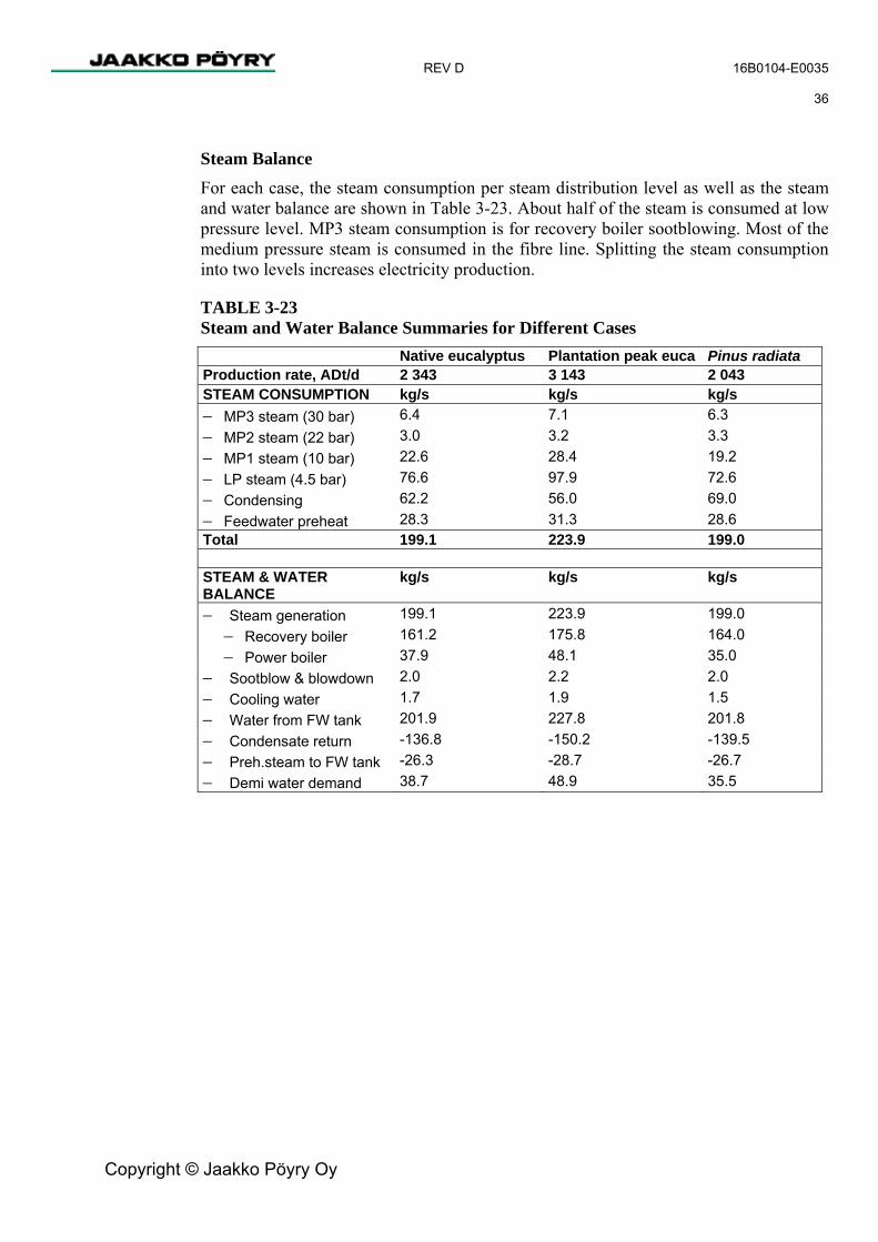
REV D 16B0104-E0035 36
Copyright © Jaakko Pöyry Oy
Steam Balance For each case, the steam consumption per steam distribution level as well as the steam and water balance are shown in Table 3-23. About half of the steam is consumed at low pressure level. MP3 steam consumption is for recovery boiler sootblowing. Most of the medium pressure steam is consumed in the fibre line. Splitting the steam consumption into two levels increases electricity production.
TABLE 3-23 Steam and Water Balance Summaries for Different Cases Native eucalyptus Plantation peak euca Pinus radiata Production rate, ADt/d 2 343 3 143 2 043 STEAM CONSUMPTION kg/s kg/s kg/s − MP3 steam (30 bar) 6.4 7.1 6.3 − MP2 steam (22 bar) 3.0 3.2 3.3 − MP1 steam (10 bar) 22.6 28.4 19.2 − LP steam (4.5 bar) 76.6 97.9 72.6 − Condensing 62.2 56.0 69.0 − Feedwater preheat 28.3 31.3 28.6 Total 199.1 223.9 199.0 STEAM & WATER BALANCE
kg/s kg/s kg/s
− Steam generation 199.1 223.9 199.0 − Recovery boiler 161.2 175.8 164.0 − Power boiler 37.9 48.1 35.0
− Sootblow & blowdown 2.0 2.2 2.0 − Cooling water 1.7 1.9 1.5 − Water from FW tank 201.9 227.8 201.8 − Condensate return -136.8 -150.2 -139.5 − Preh.steam to FW tank -26.3 -28.7 -26.7 − Demi water demand 38.7 48.9 35.5

REV D 16B0104-E0035 37
Copyright © Jaakko Pöyry Oy
Specific Power Balance Table 3-24 outlines the power produced and needed per unit tonne of output. Each case has a different production rate. Note that negative purchased power means that excess power is sold.
TABLE 3-24 Specific Power Balance Summary for Different Cases Native eucalyptus Plantation peak euca Pinus radiataProduction rate, ADt/d 2 343 3 143 2 043 GENERATED POWER kWh/ADt kWh/ADt kWh/ADt Backpressure 879 818 965 Condensing 703 475 900 Total 1 581 1 293 1 865 POWER CONSUMPTION kWh/ADt kWh/ADt kWh/ADt Total 950 816 1 075 POWER BALANCE kWh/ADt kWh/ADt kWh/ADt Power consumption 950 816 1 075 Power generation 1 581 1 293 1 865 Purchased power -631 -477 -790
Power Balance Power balance summaries for main cases are shown in Table 3-25. Because the mill will produce its own chemicals, the power from backpressure power generation will not be enough to cover the whole load. Between 50 % and 90 % of condensing power production could, however, be sold to the market (power purchase is negative = sales). The sellable power in the base case is the highest. This is because less pulp is produced and more of the material in the wood is burned.
TABLE 3-25 Power Balance Summary for Different Cases Native eucalyptus Plantation peak euca Pinus radiata Production rate, ADt/d 2 343 3 143 2 043 GENERATED POWER MW MW MW Backpressure 86 107 82 Condensing 69 62 77 Total 155 169 159 POWER CONSUMPTION MW MW MW Total 93 107 92 POWER BALANCE MW MW MW Power consumption 93 107 92 Power generation 155 169 159 Purchased power -62 -62 -67

REV D 16B0104-E0035 38
Copyright © Jaakko Pöyry Oy
Auxiliary Fuel (Natural Gas) Auxiliary fuel consumption in the lime kiln for main cases are shown in Table 3-26. It has been assumed that the available fuel is natural gas, because oil is substantially more expensive. The lime kiln will be able to use oil if natural gas is not available.
TABLE 3-26 Natural Gas Consumption in Lime Kiln for Different Cases Native eucalyptus Plantation peak euca Pinus radiata MJ/s MJ/s MJ/s Heat flow 50.0 54.6 48.0 m3n/s m3n/s m3n/s Natural gas 1.3 1.41 1.24
During normal operation the lime kiln will be the major user of natural gas. The NCG incinerator will also use a minor amount. The mill natural gas consumption will vary normally from 1.3 to 1.5 m3n/s. Natural gas flow will depend on the hydrogen production in the chemical plant. During recovery boiler start-up or load burner operation, natural gas consumption could be as high as 5 m3n/s.
3.6 Water Balances The preliminary water balance for the mill is presented in Annex III. The water balance has been calculated based on a maximum annual pulp production of 1 100 000 ADt/a.
The water balance model is based on the JAAKKO PÖYRY database for similar projects and data from similar mills. It should, however, be noted that the final water balance can be prepared only after the main pieces of equipment have been ordered, since alternative pieces of equipment of various machine suppliers feature different water consumption. For the purpose of the assessment contained in this report, the balance has been based upon all commercially available pieces of main equipment complying with the best available technology criteria. The average water consumption including cooling water make-up is summarised in Table 3-27. At the initial annual production of 820 000 ADt, raw water demand will be about 22.5 Gl/a. At an annual production of 1 100 000 ADt, when the wood raw material comprises 100 % plantation wood, the water demand is estimated at about 25.4-27.9 Gl/a. The actual water demand depends on the final choice of main equipment, but in any case it would not be higher than the given values.
TABLE 3-27 Average Water Consumption and Effluents Loads and Amounts Production Water Effluent load ADt/a m3/ADt m3/d m3/ADt m3/d 820 000 27.4 64 194 24.7 58 571 1 100 000 25.4 79 829 23.0 72 286

REV D 16B0104-E0035 39
Copyright © Jaakko Pöyry Oy
3.7 Consumption of Raw Materials Annual consumptions have been calculated based on an annual pulp production of 1 100 000 ADt/a.
3.7.1 Wood Chip Consumption Annual wood consumption m3s/a 3 650 000 Specific consumption m3s/ADt 3.65
3.7.2 Consumption of Chemicals The following list of chemicals consumed in the mill are based on an annual production of 1.1 million ADt/a. The chemicals are given for the base case and the merchant chemical production where it is relevant and will be subject to detailed design. The balanced consumption of chemicals for the base case (chemical plant being an integrated chemical plant) are contained in the OMB (Overall Material balance) in Annex IV.

REV D 16B0104-E0035 40
Copyright © Jaakko Pöyry Oy
TABLE 3-28 Consumption of Chemicals
Export Deliveries from Mill t/annum as 100% delivery
mode trucks/annum as delivered Origin
sodium chlorate 48 000 trucks 2 400 100% from site to Bell Bay port oxygen 49 000 trucks 2 450 100% from site hydrogen peroxide 12 000 trucks 600 59.5% from site to Bell Bay port nitrogen 14 000 trucks 700 100% from site Major Deliveries to Mill t/annum as 100% delivery
mode trucks
(ships)/annum as delivered Origin
salt (merchant chemical plant) 50 000 boat (20) 95% ship from SA or WA to pulp mill berth
salt (base case: IDP chemical plant) 35 000 boat (14) 95% ship from SA or WA to pulp mill berth
sulphuric acid (base case: IDP chemical plant) 300 trucks 15 98% ship to Bell Bay, truck to site sulphuric acid (merchant chemical plant) 23 238 trucks 1 186 98% ship to Bell Bay, truck to site hydrochloric acid(base case: IDP chemical plant) 200 trucks 31 32% ship to Bell Bay, truck to site caustic soda (base case) 5 075 trucks 501 46% ship to Hobart, truck to site caustic soda (merchant option)* 18 700 boat (2) 46% ship to pulp mill berth sulphate 14 151 trucks 708 100% ship to Bell Bay, truck to site peroxide (base case: IDP chemical plant) 2 200 trucks 147 59.5% ship to Bell Bay, truck to site peroxide (base case: with final P stage) 11 093 trucks 740 59.5% ship to Bell Bay, truck to site sand 3 000 truck s 150 100% truck from Scottdale, Tasmania limestone 24 750 trucks 750 100% truck from Winkligh, Tasmania burnt lime 6 875 trucks 229 100% truck from Railton, Tasmania magnesium sulphate 250 trucks 13 100% ship to Bell Bay, truck to site urea 1 551 trucks 78 100% truck from Bell Bay aluminium sulphate 1 100 trucks 55 100% truck from Bell Bay baling wire 1 334 trucks 67 100% truck from Bell Bay

REV D 16B0104-E0035 41
Copyright © Jaakko Pöyry Oy
Minor Deliveries to Mill
t/annum as 100% delivery mode
trucks (ships)/annum
as delivered Origin
defoamer 550 trucks 28 100% truck from Bell Bay talc 550 trucks 28 100% truck from Bell Bay sulphamic acid 20 trucks 1 100% truck from Bell Bay phosphoric acid 165 trucks 15 54% truck from Bell Bay sodium carbonate 388 trucks 19 100% truck from Bell Bay flocculation aids 132 trucks 7 100% truck from Bell Bay filtering aids 204 trucks 10 100% truck from Bell Bay boiler water & steam chemicals 20 trucks 1 100% truck from Bell Bay miscellaneous 20 trucks 1 100% various
* when no own caustic is produced on site
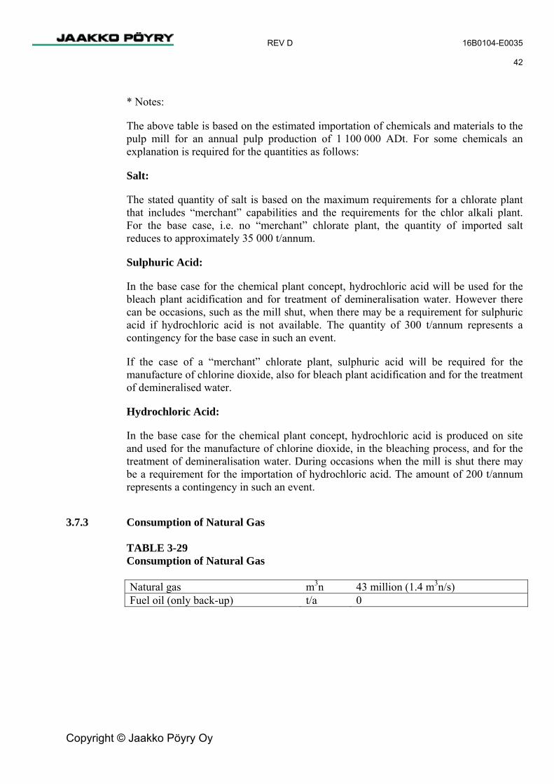
REV D 16B0104-E0035 42
Copyright © Jaakko Pöyry Oy
* Notes:
The above table is based on the estimated importation of chemicals and materials to the pulp mill for an annual pulp production of 1 100 000 ADt. For some chemicals an explanation is required for the quantities as follows:
Salt:
The stated quantity of salt is based on the maximum requirements for a chlorate plant that includes “merchant” capabilities and the requirements for the chlor alkali plant. For the base case, i.e. no “merchant” chlorate plant, the quantity of imported salt reduces to approximately 35 000 t/annum.
Sulphuric Acid:
In the base case for the chemical plant concept, hydrochloric acid will be used for the bleach plant acidification and for treatment of demineralisation water. However there can be occasions, such as the mill shut, when there may be a requirement for sulphuric acid if hydrochloric acid is not available. The quantity of 300 t/annum represents a contingency for the base case in such an event.
If the case of a “merchant” chlorate plant, sulphuric acid will be required for the manufacture of chlorine dioxide, also for bleach plant acidification and for the treatment of demineralised water.
Hydrochloric Acid:
In the base case for the chemical plant concept, hydrochloric acid is produced on site and used for the manufacture of chlorine dioxide, in the bleaching process, and for the treatment of demineralisation water. During occasions when the mill is shut there may be a requirement for the importation of hydrochloric acid. The amount of 200 t/annum represents a contingency in such an event.
3.7.3 Consumption of Natural Gas TABLE 3-29 Consumption of Natural Gas Natural gas m3n 43 million (1.4 m3n/s) Fuel oil (only back-up) t/a 0

REV D 16B0104-E0035 43
Copyright © Jaakko Pöyry Oy
3.8 Description of Process Areas and Systems The process description in the pre-engineering phase defines the basis for the cost estimate only. The final selection of equipment will take place during the commercial negotiations between Gunns and equipment suppliers. For this reason the process and equipment descriptions are general and not definitive. However the selected equipment will comply with the best available technology.
3.8.1 Wood Handling
General The wood handling activities are chipping, chip conveying and chip screening operations.
The pulp mill will use the existing chip mills to supply wood chips to the site. The wood raw material is received as debarked roundwood at the existing North and South Mill of the Longreach Chip Mill facility of Gunns Ltd.
The most important factor in chip quality management is to maximise the acceptable fraction and then maintain it in as uniform a size distribution as possible. Oversize and undersize fractions must be kept low. A new chip screening system with chip silos is to be installed to promote high chip quality.
A new chipping line will be built to ensure the required chip production capacity and quality is met. The new chipping capacity will be 5 million tonnes/annum. The new line will consist of the existing log receiving deck and feed to the chipper. The chips will be conveyed from the new chipping line to the new chip pile which is to be located between the existing chip piles. The chips will be fed to the pile with a slewing belt conveyor. A new reclaimer will be located under the chip pile to reclaim the chips and transport them to the pulp mill with belt conveyors. The new line will comprise a log washing stage where the log washing water will be circulated. A small amount of make-up water will be required - reclaimed storm water will be used and when that is not available fresh water). The respective amount of effluent will be sent to the pulp mill effluent treatment plant. The new chipper will be erected inside a totally closed concrete building.
Modifications to the existing chip mills will also be required to meet the chip production capacity and quality. At the South Mill, the log decks for the 96’’ and 153’’ chippers will be modified from a width of 12 m to 15 m due to the longer wood length. The housing around the chippers will be closed and noise reduction plates installed inside the building. A by-pass chute around the existing chip screening will be installed to the existing ship loading line which will be modified to feed to the new chip conveyor delivering chips to the pulp mill. One railroad rail will be installed to the north of the existing rails in the log yard and the existing rails will be demolished. The maintenance workshop for mobile equipment will be relocated to a more practical place. The refuelling station will also be relocated.

REV D 16B0104-E0035 44
Copyright © Jaakko Pöyry Oy
At the North Mill, the existing incoming weighbridge will be relocated to act as an outgoing weighbridge. A new larger incoming weighbridge will be installed. The waste conveyor from the infeed log deck will be relocated by 90° and the unused log conveyors will be demolished. The disused burner will be removed and the crib-room relocated. A by-pass chute around the existing North mill chip screening will be installed to the loading line which will be modified to feed to the new chip conveyor delivering chips to the pulp mill. A whole truck chip unloading station will be installed alongside the existing one.
The log storage area is limited at the mill and will remain unchanged. The operation of the wood yard and chipping area is continuous, 24 hour of operation.
Process Description Plantation and native eucalyptus logs will be chipped with the existing Nicholson (for plantation wood) and Black Clawson (for native wood) chippers. The new chipper will process the plantation logs.
Chipped wood will be transferred to the existing chip piles with belt conveyors. New conveyors will be installed to fulfil the capacity requirements.
The wood chip mixture will be made in the existing chip piles storage by drag chain reclaimers. Reclaimers will be continuously filled with the bulldozers from the chip piles.
It will be possible to run plantation and native eucalyptus in campaigns also if needed. In that situation, the chip silos will be fed from either the plantation chip pile or the native chip pile.
Chips will be reclaimed to a collecting belt conveyor and transferred to two chip silos each with a volume of 10 000 m3. The conveyor will be enclosed with walkways on both sides. The design of the conveyor system will be such as to pay special attention to noise dissipation. Metal particles will be removed from the collecting conveyor before the silos.
There are several advantages favouring intermediate chip storage in silos near to the new pulp mill. The evidently long distance from the drag chain reclaimers to the digester plant causes long delays in changes of chip conveying. The control and operation of chip feed to the digester plant will be more stable if silos are installed. Chip silos also enable flexible manning to leave out night shift at chip storage area. Chip silos before chip screening enable steady load on screening to promote good chip quality. The digester chip bin is small in volume with no substantial buffer capacity and the chip bin level is targeted to be constant to facilitate efficient chip pre-steaming. Chip silos also equalise capacity changes in fibre line.
After the silos the chips will be fed via screening to a digester plant chip bin. Chips will be transported from the silos with screw reclaimers to a collecting conveyor equipped with belt scales. The chip silo screw reclaimers and belt conveyors after silos will be inverted controlled based on the level of the digester chip bin.

REV D 16B0104-E0035 45
Copyright © Jaakko Pöyry Oy
The purpose of screening is to form as even as possible a chip size distribution for cooking. Particles that are unsuitable for processing will be removed and excessively long chips will be rechipped and returned to screening. Oversize particles will be removed with a scalper screen prior to chip screening operations. Oversize chip fractions from scalper screen and chip screening will be led to a rechipper. Rechipped wood material will be led back to screening. Fines from screening will be led out from the process.
Accept chip fraction will be transferred with a screw conveyor to a belt conveyor equipped with a magnet to remove metal particles. The digester chip bin silo will be fed with a belt conveyor equipped with a belt scale.
3.8.2 Fibre Line
General The fibre line consists of the cooking plant, screen room including equipment for deknotting, screening and reject handling, brown stock washing, the oxygen delignification plant with white liquor oxidation and the bleaching plant.
The main criterion for selecting the fibre line design concept is to ensure the best possible product quality with the maximum production of a single-line mill at minimum environmental impact.
The fibre line concept will be based on modern cooking, washing and bleaching technology. The final selection of individual machinery will be made based on technical and economic criteria.
Refer to Process Orientation Diagrams 16B0104-02034.
Cooking
In cooking, the fibres of the wood material are released from the wood structure by dissolving the organic material out with cooking chemicals at elevated temperature. The cooking chemicals, hydrogen sulphide ions and hydroxide ions, degrade the lignin structure and make the lignin soluble in water. At the same time the carbohydrates are attacked by the hydroxide ions resulting in lower pulp yield and lower pulp strength. The rate of reaction for lignin and carbohydrate degradation can be affected by the temperature.
The cooking plant consists of a chip feeding system, chip bin and a modern technology cooking system, either the Compact Cooking process or the Lo Solids process.

REV D 16B0104-E0035 46
Copyright © Jaakko Pöyry Oy
a. Compact Cooking
In the Compact Cooking process the temperature is kept deliberately low in order to minimise the degradation of carbohydrates. Chips enter a special atmospheric bin which serves a combined function of a chip bin (providing buffer time and reducing chip feed variations) and as an impregnation vessel. A mixture of white and black liquor is added to this impregnation bin by extracting from the upper digester screen sections and adding below the chip level via a central pipe. The liquor to wood ratio is kept high and the temperature is approximately 1000C. A small amount of liquor is withdrawn from the impregnation bin screens and sent to evaporation. The chips are removed from the impregnation bin after approximately 60 mins retention time by an outlet device and sent to the high pressure feeder which transports the chips from a low pressure exiting the impregnation to the digester which operates at high pressure. The digester is divided into three zones. The upper and lower cooking zones have a total of 180 minutes retention while the washing zone has an additional 50 minutes retention. The upper digester screen separates the two cooking zones and the washing screen is located below the lower digester screen section.
In the Compact Cooking the whole digester, except the washing zone, is used for cooking. The actual cooking temperature (typically 144 – 1460C) depends on the raw material and the production level. The liquor to wood ratio is also maintained high. The top separator separates the chips from the transporting liquor and allows the chips to fall to a steam phase at the digester top where they are subjected to direst steam to reach the final cooking temperature. White liquor is added through an internal header at the digester top and adjusted according to the residual liquor in the upper digester extraction liquor. The chip level in the digester is measured by three mechanical level indicators. The black liquor extracted from the upper digester screen section consists of four screen rows is mixed with the transfer circulation liquor before it is re-circulated to the impregnation bin. The lower digester screen also consists of four rows of screens which are located close to the digester bottom. The black liquor from the lower cooking zone and the displaced liquor from the washing zone are extracted from this screen section and sent to evaporation. The washing zone uses filtrate from the brown stock washing as the wash liquor. The filtrate is distributed through the vertical and horizontal nozzles and through the bottom scraper arms. The pulp is discharged at 10% consistency to the blow tank by the outlet device.

REV D 16B0104-E0035 47
Copyright © Jaakko Pöyry Oy
b. Lo Solids
In the Lo Solids process, the chips are heated in a chip bin to 1000C by clean steam which has been generated in a reboiler. The chips are discharged from the chip bin by a double screw conveyor to a chip tube. After the chip tube three pumps in series convey the chips directly to the impregnation vessel which operates at 100 - 1100C. The impregnated chips are discharged from the impregnation vessel by an outlet device and transferred via the transfer circulation pump to the digester top separator. At the digester top medium pressure steam is added to heat the chips to approximately 1400C. After the first cooking zone, the chips enter the upper extraction screen where liquor is extracted from the upper most set of screens. The chips then meet the fresh liquor from the cooking circulation (2nd row of upper digester screen set). This liquor heats the chips to the 2nd cooking stage temperature of approximately 1500C. White liquor and liquor extracted from the bottom set of screens in the digester are combined and pre-heated by extracted black liquor before being added to the digester cooking circulation. This liquor displaces the liquor from the first cooking zone. A portion of this liquor flows upwards to heat the chips from the first cooking stage. The remainder of the liquor flows together with the chips downward to the 2nd cooking zone. After the 2nd cooking zone, the rest of the liquor is extracted from the digester at the lower extraction screens. Washing in the digester is accomplished by passing wash liquor in the counter-current direction through the pulp in the digester bottom wash zone. This liquor passes upwards in the pulp column and is continuously extracted through the lower extraction screens. The pulp is discharged at 10% consistency to the blow tank by the outlet device.
c. General Cooking Process Description
In the following paragraphs, a two-vessel steam/liquor phase continuous digester with a separate vessel for impregnation is described. However it has to be noted that there are variations in this following process description (Lo Solids or Compact Cooking) of the different suppliers and therefore the description is not necessarily the final selection.
Screened chips will be conveyed to a chip bin and steamed with either fresh low pressure steam or steam produced in a reboiler. The purpose of the steam is to remove air entrained in the chips and to bring the chips to a uniform moisture content and temperature. The bin has a retention time of approximately 30 minutes.
The chips flowing from the bin will be metered and proportioned by a chip feeding system to the top of the chip impregnation tower. The chip feeding system controls the production through the digester. In the impregnation vessel, the chips are impregnated with hot black liquor, which has been recycled from the digester, before they enter the digester.
After impregnation, the chips will be discharged and transferred to the digester top. In the digester the chips are heated to cooking temperature.
The final heating to the desired cooking temperature is done by means of direct MP steam at the digester top. By using direct steam, the heat is distributed evenly throughout the cross-section of the digester. Having a part of the chip column above the liquor level enables the packing degree to be controlled by adjusting the distance between the top of the chip column and the liquor level.

REV D 16B0104-E0035 48
Copyright © Jaakko Pöyry Oy
A vertical up-going top separator at the top of the digester separates chips from the returning liquor. The chip level is controlled by means of three mechanical level indicators, while the liquor level is controlled by an ordinary and gamma type level transmitter and the extraction valve.
Depending on the type of process chosen, the digester can consist of two concurrent cooking zones with screen sets. The cooking is performed in the whole digester, excluding a heat lock zone at the bottom of the digester, giving a total cooking time of approximately four hours. The cooking temperature is approximately 140 - 150oC. The weak black liquor from the digester is led to the evaporation plant through fibre filters.
Any concentrated non-condensable gases (CNCG) from the cooking plant will be cooled and led to the CNCG collection system. Modern continuous digester plants, generally, do not generate CNCG when cooking eucalyptus due to the use of a reboiler and indirect cooling of weak black liquor. However the processing of Pinus radiata results in CNCG from the turpentine decanter, turpentine storage tank, and the contaminated condensate tank. The CNCG’s that are generated will be collected and incinerated in the odour abatement system of the mill.
The plant design is such that there is a small amount contaminated condensate from the cooking plant which is collected and sent to the foul condensate tank in the evaporation plant.
The exhaust gases from the chip bin are cooled in a condenser and led to the diluted non-condensable (DNCG) collection system.
The first stage of brown stock washing is performed at the bottom part of the digester, which is designed for handling the whole amount of wash liquor coming from the brown stock washing system, without jeopardising the good movement of the chip column. Wash liquor from the following wash train is pumped with a high-pressure pump into the bottom of the digester. A counter-current up-going net liquor flow will be adjusted to maintain a desired dilution factor.
The cooled wash liquor added to digester bottom cools the hot pulp to 90-95°C before it is blown to the pulp blow tank. The blow tank is designed for low consistency discharge.
The cooking plant comprises the following main tanks:
− Blow tank m3 4 000
− Hot water tank m3 300

REV D 16B0104-E0035 49
Copyright © Jaakko Pöyry Oy
Screen Room In screening the uncooked particles and impurities are separated from the accepted fibre flow.
The screening consists of knot separation, knot washing and knot returning systems, pressurised screening in three stages and a reject dewatering system.
From the cooking plant blow tank, pulp is pumped to two parallel combined pressurised screens performing knot separation and primary screening in one unit. The accept flow from the combined screens is led directly to the pre-oxygen washing stage.
The knot reject flow from the combined screens is fed to the knot washer, where the knots are separated and returned to cooking. The accept flow from the knot washer is led back to the screen room feed through a dump tank and sand separator.
The reject from primary screening is handled in the pressurised secondary and tertiary screens in a normal cascade coupling. All the screens are equipped with slotted screens and provided with a light reject separation system.
The reject from the tertiary screen goes through sand separation to the reject washer where the good fibres are washed off to the accept line in the same way as in the knot washer. The reject flow from the reject washer is fed through the screw press to the screw conveyor to be discharged from the process. The screening reject is burned in the power boiler. The accept flow from the reject washer goes back to the tertiary screen feed.
The screening plant comprises the following main tank:
− Filtrate buffer tank m3 4 000
− Dump tank m3 300 − Filtrate tank m3 30 − Filtrate tank m3 150 − Level tank m3 300
Pre-oxygen Washing
In washing of pulp the process chemicals and dissolved organic material are separated from the fibre pulp flow as weak black liquor for recovery and production of energy. A drum displacer or press drum type of equipment can be used. Additionally pressure diffusers could be used as part of the pre-oxygen washing directly after the digester and before the blow tank storage. The different types of washing equipment are described in the following text.

REV D 16B0104-E0035 50
Copyright © Jaakko Pöyry Oy
The drum displacer Washer (DD) consists of a solid steel drum surrounded by a pressurised housing. The drum is partitioned with ribs that form compartments. Near the bottom of the compartment is a screen plate, which acts as a barrier as pulp fills the channel above the screen. Once pulp is in the compartment and in the washing zone, filtrate is displaced through the mat and through the screen into the channel beneath the screen. The displaced filtrate exits the wash zone through a valve located at the end of the drum. Pulp is fed either at low or medium consistency to the web-formation section of the drum displacer. In the first washing stage the pulp is washed with filtrate from the second stage. The washer can be equipped with up to four washing stages and the wash liquor can be circulated counter-currently through the stages. No filtrate tanks are needed between the stages. After washing, the pulp mat travels through a vacuum stage to increase the consistency of the fibre cake. The pulp is released at medium consistency. The washing operation is carried out under pressurized, air-free conditions.
The wash (compact) press is a two drum equipment which relies on both pressing and washing the pulp. The incoming pulp is fed into the two distribution screw trays, one for each drum. The distribution screws distribute pulp along the working width of the machine. In the decreasing space between the drum and the flap, into which the pulp is forced by the drum rotation, the pulp is compressed and dewatered to approximately 15 % consistency. This pulp at relatively high consistency is washed in the zone between the vat and the drum. Wash liquor is injected into the pulp by nozzles placed lengthwise along the drum. Decreasing pulp area provides further dewatering all the way to the press nip where the two pulp webs meet. At pressing a final consistency of approximately 32 % is reached. Doctor blades remove the pulp from the drums to a shredding and conveying screw, which transports it axially to the dilution screw where the pulp is diluted to the required consistency. In the free drum area between the shredder screw and the distribution screws, nozzles clean the drums by means of internal filtrate pumped from the filtrate tank. All filtrate, which is displaced and dewatered from the pulp mat flows inside drum channels and is collected in chambers at the end of the drums. From these chambers the filtrate flows down to the filtrate tank.
The pressure diffuser is a fully enclosed unit to which the pulp is fed to at medium-consistency. Depending on the specific vendor, the pulp moves up (or down for an alternative vendor) the diffuser through an opening between the vessel wall and a cylindrical screen assembly. Wash liquor is distributed into the vessel through a piping system that runs the length of the vessel. It is displaced through the pulp mat, through the screen assembly, and into the centre chamber, exiting through an outlet at the bottom (or top for an alternative vendor) of the diffuser. The tapered screen assembly reciprocates up and down. The tapered shape forces the filtrate back through the screen and "wipes" the pulp mat from the screen, thus preventing screen plugging. The washed pulp from the top (or bottom for an alternative vendor) of the pressure diffusers is discharged to the blow tank.
In the following process description, the press washer type washing system has been described.

REV D 16B0104-E0035 51
Copyright © Jaakko Pöyry Oy
Pre-oxygen washing takes place in two wash presses in series. After de-knotting and screening, pulp is fed at low consistency to the first wash press. Washed pulp is conducted by a screw conveyor to the drop-leg of an MC pump, which feeds pulp to the second wash press, which is an MC feed wash press. After the press, pulp is taken by a screw conveyor to the drop-leg of an MC pump and further into the oxygen stage.
Circulated filtrate from post-oxygen washing is used as washing and dilution liquor in the last pre-oxygen press. The filtrate from the last wash press is sent counter-currently back to the digester bottom through the first wash press and a liquor buffer tank. The volume of the liquor buffer tank corresponds to the volume of the blow tank.
Oxygen Delignification In oxygen delignification the removal of lignin compounds from the fibre structure is continued.
The oxygen delignification plant consists of two pressurised oxygen reactors, a blow tank and a white liquor oxidation system.
After the last pre-oxygen wash press, pulp is pumped by an MC pump via an oxygen mixer to the first reactor, with a retention time of approximately 10-20 minutes. Caustic (oxidised white liquor) for pH control is added to the drop-leg of the feeding MC pump.
Between the oxygen reactors there is a MC booster pump, which gives extra head for the second oxygen reactor and a second oxygen mixer. For temperature control medium-pressure steam is added together with oxygen to the pulp in the mixer. From the mixer, pulp is transferred via an MC flow discharger, which ensures a uniform flow in the reactor that has a hemispherical bottom, to the second oxygen reactor with a retention time of approximately 60 minutes.
From the second oxygen reactor, pulp is discharged by a flow discharger to the blow tank for effective degassing. From the blow tank, pulp is fed to the post-oxygen washing system.
In order to use white liquor instead of caustic (NaOH) for oxygen bleaching the Na2S-content of the white liquor has to be oxidised in a process known as white liquor oxidation. In white liquor oxidation sodium sulphide (Na2S) is oxidised to sodium thiosulphate (Na2S2O3). Sodium thiosulphate reacts further to sodium sulphite (Na2SO3) and sodium sulphate (Na2SO4). The pressurised white liquor oxidising system consists of a stirred reactor and heat exchangers. White liquor is pumped to the upper part of the reactor and oxygen is fed to the reactor in relation with white liquor flow. Oxygen is distributed through small nozzles to three levels near the vertical agitator blades. The oxidation reactor is operated at 5-8 bar(g) pressure and a temperature of 120-150 ºC.
The oxidation reactions are exothermic, and excessive heat is removed by cooling the reactor by water cooled cooling coils located inside the reactor or in a separate heat exchanger.
Oxidised white liquor is pumped with a booster pump directly to the consumption places.

REV D 16B0104-E0035 52
Copyright © Jaakko Pöyry Oy
Inert gases from the reactor are removed in the blow tank after the reactor, collected, and conveyed to the bleach plant vent gas scrubber where they join with the alkaline gases at the discharge of the scrubber. The oxygen delignification plant comprises the following main tanks and reactors:
− First oxygen reactor m3 230
− Second oxygen reactor m3 1 200 − Filtrate tank m3 150 − BS storage tower m3 5 000 − Filtrate buffer tank m3 5 000 − Filtrate tank m3 70
Post-oxygen Washing The post-oxygen washing system before the bleaching plant consists of two MC feed wash presses in series with a brown stock storage tower between the presses.
At the bottom of the oxygen delignification blow tank, pulp is diluted to a consistency of 6-8 % and pumped to the first post-oxygen wash press. After the press, pulp is conducted by a screw conveyor to the drop-leg of an MC pump and pumped to the brown stock storage tower.
The brown stock storage tower, with a volume of 5 000 m3, acts as a buffer between brown stock operation and bleaching. It also accomplishes a leaching effect of organic substances before final washing prior to bleaching. The tower has an MC discharge.
From the brown stock storage tower, pulp is transferred by a discharge scraper to an MC pump feed chute and to an MC pump, which feeds pulp at a consistency of 6-8 % to the last wash press prior to bleaching.
After the press, pulp is conducted by a screw conveyor to the drop-leg of an MC pump and further into the first bleaching stage.
Secondary condensate is used as washing liquor on the last wash press. Due to the accumulation of non-process-elements in the recovery liquor cycle it has not been accepted modern technology to close the bleach plant filtrate cycles. Additionally closing up the filtrate systems will lead to increased bleaching consumptions and poorer effluent characteristics. However the system will be designed so that filtrate from the EOP stage of the bleach plant can, in the future if research and developments progress successfully, be recycled back as washing liquor on the last press. The filtrate from the wash press is sent counter-currently back to the brown stock washing system through a liquor buffer tank. The volume of the liquor buffer tank corresponds to the volume of the brown stock storage tower.
The department will be provided with a spill recovery system, which will recover all contaminated spills, emptying equipment or tanks to a spill liquor sump located in the brown stock area of the fibre line.

REV D 16B0104-E0035 53
Copyright © Jaakko Pöyry Oy
Bleaching Bleaching is carried out in a four-stage sequence: D - EOP – D1 – D2. The first D stage will have the capability of operating with high temperature and under strong acid conditions.
At the beginning of the bleaching sequence (D-EOP), the removal of organic compounds from the fibre structure is further continued. In the latter part of the sequence, the residual chromophoric organic compounds will be converted into water-soluble substances and subsequently removed from the pulp by washing it with hot water. The resulting bleached pulp is chemically very clean cellulose, and features high brightness.
The sequence consists of acidic and alkaline stages to be able to remove the reaction products of the previous stage out from the fibre flow. The chemical reactions takes place in reaction towers during the retention time at certain temperature specific for each stage. In between the reaction stages the dissolved reaction products are washed out.
Washing can be made by displacer drum or press drum type of washers. The following process description refers to press washer type washing.
From the last brown stock wash press after the brown stock storage tower, pulp is transferred to an MC pump feed chute, where sulphuric acid or hydrochloric acid is added. Whether sulphuric or hydrochloric acid is used has no impact on the bleach plant effluent. Pulp is pumped with an MC pump at 11-12 % consistency to up-flow tower operating at a high temperature of 90-95oC. The high temperature is reached by heating the dilution liquor of the last brown stock wash press with MP steam. The retention time in the reactor is about 120 minutes. From the A tower, pulp is discharged into the standpipe of the MC pump feeding the pressurised D0 reactor with a retention time of 15 minutes. In the chemical mixer, chlorine dioxide is added to the pulp before the reactor. The temperature in the reactor is about 85oC.
Pulp is discharged from the D0 reactor into the MC drop-leg of the MC pump feeding the wash press. Circulated filtrate from the D1 stage is used as washing liquor in the press.
After the D0 stage wash press, magnesium sulphate and sodium hydroxide are mixed into the pulp through the dilution liquor in the press dilution screw or injected into the drop-leg of the MC pump. Filtrate from the EOP stage is used as dilution liquor.
Magnesium sulphate is a compound which is added to the pulp to act as a protector against carbohydrate degradation by transition metals during the oxygen delignification operations. It is required for the processing of softwood but not necessarily for the processing of eucalyptus.

REV D 16B0104-E0035 54
Copyright © Jaakko Pöyry Oy
After the dilution screw, pulp drops to an MC pump feed chute where peroxide is added. An MC pump feeds the pulp through a chemical mixer and booster MC pump to a pressurised up-flow EOP reactor. In the chemical mixer, gaseous oxygen and MP steam are mixed into the pulp. The retention time in the EOP reactor is 60-70 minutes. The temperature is approximately 90-100oC.
Pulp is discharged from the reactor by a flow discharger to a blow tank in where it is diluted to about 6-8% and pumped to the EOP stage wash press. Hot water is used as washing water in the press and circulated filtrate from D1 stage is used for screw dilution.
From the EOP stage wash press, pulp drops into an MC drop-leg and is pumped through a chemical mixer for chlorine dioxide to an atmospheric D1 tower. The D1 tower is an up-flow tower, but operating at a lower temperature of about 70-75°C.
Pulp is discharged from the tower into an MC drop-leg and pumped at a consistency of about 6-8% directly to the D1 stage wash press. Filtrate from the D2 stage is used as washing liquor in the press.
After the D1 stage wash press, sodium hydroxide is mixed into pulp through the dilution liquor in the press dilution screw, or injected into the drop-leg of the MC pump. Filtrate from the D2 stage is used as dilution liquor.
After the dilution screw, pulp drops to an MC drop-leg and is pumped through a chemical mixer for chlorine dioxide addition to an atmospheric D2 reactor. The size of the D2 reactor is equal to that of D1 towers. The operating temperature is about 70-75°C.
There will be the possibility to operate the D2 stage as a peroxide stage by adding hydrogen peroxide (instead of using chlorine dioxide). If the merchant chemical plant is the chosen concept on for the chemical plant then the final bleach stage will be a P stage.
Pulp is discharged from the tower into an MC drop-leg and pumped at a consistency of 6-8 % to the D2 stage wash press. White water from the drying machine is used as washing water in the press and for screw dilution.
From the D2 stage wash press, pulp drops into an MC drop-leg and is pumped to three parallel bleached pulp HD towers before feeding to the drying machine. There will be two HD towers with a volume 10 000 m3 and one with a volume 5 000 m3.
Acid vents from the bleaching plant are collected and led to the bleaching plant scrubber. Alkaline vents are collected and blown to the scrubber stack. The acid vents are scrubbed with alkaline sodium bisulphite water to absorb the residual chlorine dioxide from the vent gases. The sodium bisulphite is produced on site in the NCG destruction system.

REV D 16B0104-E0035 55
Copyright © Jaakko Pöyry Oy
Alkaline effluent from the EOP stage and acid effluent from the D stage are filtered to recover fibres from the press filtrate. The system will be designed so that filtrate from the EOP wash stage of the bleach plant can, in the future if research and developments progress successfully, be recycled back as washing liquor on the last press in the post oxygen delignification stage.
The temperature of the effluents will be about 85°C. The bleach plant effluent is cooled at the bleaching plant with heat exchangers. The acidic effluent heat is used for heating of the chlorine dioxide water and white water from the drying machine. The alkaline effluent heat is recovered in a heat exchanger to produce hot water.
The bleach plant comprises the following main tanks:
− A tower m3 2 200
− D0 tower m3 300 − EOP reactor m3 1 500 − D1 tower m3 2 200 − D2 tower m3 2 200 − D0 filtrate tank m3 70 − EOP filtrate tank m3 70 − D1 filtrate tank m3 120 − D2 filtrate tank m3 120 − HD tower 1 m3 10 000 − HD tower 2 m3 10 000 − HD tower 3 m3 5 000 − MgSO4 pumping tank m3 25 − Talc pumping tank m3 25 − Peroxide pumping tank m3 3
Drying Machine
The drying machine concept is based on one twin-wire type machine, including a press section with two shoe presses, airborne pulp dryer, cutter layboy and three baling lines.
The drying department consists of the following parts:
− Stock handling − Bleached stock cleaning − Broke handling − White water system − Wire and press section − Dryer including heat recovery and web cooler − Sheet cutters − Baling lines

REV D 16B0104-E0035 56
Copyright © Jaakko Pöyry Oy
In bleached stock screening the physical cleanliness of the pulp is ensured by removing small impurity particles, like sand, fibre bundles and sticks. In drying the fibre pulp is formed to web (a web is the term used for the continuous sheet of pulp formed on the wire of a pulp machine) by removing water acted as carriage media on the wire, with presses and by evaporating. The web is cut into sheets, which are baled and packed into transportation units.
Stock is stored in two 10 000 m3 and one 5 000 m3 storage towers with agitators at the bottom of the towers. Stock is diluted at the bottom of the tower to 4–5 % by using water from the white water tower and stock is diluted and consistency controlled to about 4 % on the suction side of the stock pump. Stock is pumped to one of the stock chests. The tanks are equipped with agitators. Dilution water is taken from the white water tank.
Broke is the term used for pulp fiber that is not processed through to the baling line and pulp storage. Broke can also consist of repulped bales of pulp. It is recovered and recycled through the process and stored in the broke tower. Broke from the broke tower is consistency controlled and pumped to the stock chest.
Stock is consistency controlled after the stock chest and pumped to the bleached stock cleaning. The bleached stock cleaning is based on four-stage screening with slotted screens followed by two-stage forward cleaning and two-stage reverse cleaning. Both heavy and light rejects are removed. The fourth-stage screen is equipped with a separate guard screen with 5 mm holes for removing oversized dirty particles before the cleaners. The accept stock from the first-stage reverse stage is returned to the stock chest.
Otherwise, the system is cascaded. Accept stock from the first stage is led to the machine chest, which is equipped with agitators. From the machine chest, stock is pumped to the suction side of the fan pump. This flow is flow controlled and the production of the machine is controlled with this flow.
Dilution water for the screens is taken from the white water tank and the dilution water to the cleaners is taken from the same pipeline via a dilution head tank.
The headbox and wire section consist of a hydraulic headbox including basis weight profile control in cross-machine direction and a double wire section, where the web is dewatered in both directions. The water removal is controlled so that the pressure of the stock between the wires is kept constant. Removed water is mainly led to one side of the machine, but a smaller portion is led to the other side to keep the pressure constant in cross-machine direction. The twin-wire section is followed by a felted press nip and a shoe press pressing the web between the bottom wire and the top felt. The wire section is followed after the first open draw by a double-felted shoe press.
Shower water is produced by heating mill water in the heat recovery system and adding also cooling water from the vacuum pumps after filtering to the warm water tank.
The vacuum system consists of three vacuum pumps serving three felts and vacuum boxes at the end of the wire section. Vacuum is needed in the twin-wire section only during start-ups. The felt water is collected into a tank and returned after filtering to the white water tank.

REV D 16B0104-E0035 57
Copyright © Jaakko Pöyry Oy
Broke is led from the first open draw to the wet end pulper and broke after the shoe press is conveyed by a broke conveyor to the same pulper. Dilution water is taken from the white water tower and the broke is pumped to the broke tower during web breaks. Tail trims from the wire section are returned to the stock tank during normal operation.
The web is led to the dryer. The web is carried through the dryer between blow boxes and it is turned to the next deck by turning rolls at both ends of the dryer. The air in the dryer is circulated by circulation fans through the blow boxes. Humid air is blown out from the dryer through the air/air heat exchangers, where the drying air is heated with exhaust air. The heat in the exhaust air is utilised for heating process water for use as shower water and for heating the machine hall ventilation air. Drying and exhaust air flows are controlled according to the humidity of the exhaust air and the air balance.
Condensate from the dryer is collected into a condensate tank. The condensate tank is connected to a condenser by an orifice plate for condensing the blow-through steam. The condensate is pumped to a heat exchanger to be cooled to 100°C. The heat is utilised for heating the white water, which is taken from and returned to the wire silo.
Broke pulp after the dryer and from the cutter is led to a pulper. Dilution water is taken from the white water tower. Broke pulp is pumped to the broke tower.
The web from the dryer is cut into two parts between two nips and the webs are led into two cutters. The web is cut into sheets and they are overlapped twice before entering the layboy parts of the cutter. Only one of the cutters is used for cutting the wrappers. The set of bales from the upper cutter is lowered to the base level.
The baling consists of three baling lines, which can produce:
− Wrapped and tied 250 kg bales unitised into 2000 kg units − 1000 kg unwrapped bales unitised into 2000 kg bales
The bales are unitised into 2000 kg lifting units in three unitisers with 7 x 3 mm wire and the units are conveyed to the discharge conveyors.
The units are loaded inside the bale storage area by a 24 t clamp truck into a terminal truck. The terminal truck transports the units to the harbour and the units are unloaded into the harbour storage by clamp truck or are lifted straight into the ship in 24 t (12 units) loads. The terminal trucks are normal road trailers with fixed canopy to cover the pulp units from rain and dirt. Two truck and trailers in continuous day-round operation will be used to transfer the produced pulp from mill to the wharf warehouse.
All pulp that is not taken directly to ship loading will be transferred to the pulp warehouse immediately after production. The warehouse for storing and shipping the pulp is located about 1 500 m from the pulp mill. At the end of the pulp production line there is only an emergency stocking place for smaller amounts of pulp.
Pulp will be delivered to the markets using purpose built pulp ships.
At the wharf warehouse the trailers will be unloaded and pulp units piled into stacks by fork lift trucks. The fork lift trucks in the wharf warehouse are similar to the ones at the mill and are equipped with bale clamps capable of handling four units at the same time.

REV D 16B0104-E0035 58
Copyright © Jaakko Pöyry Oy
In the wharf warehouse different pulp grades and qualities are piled into separate stacks. Normally stacks are four units high. In an emergency situation, five high piling could be used. In that case horizontal strapping of units will be used to stabilise the stacks.
The total floor area of the pulp warehouse is designed to be 20 000 m2. Under normal operating conditions the warehouse could store about 50 000 tons of pulp. Under extreme situation an additional 20 000 tons could be placed under cover using the warehouse aisles.
The dimensioning of the pulp warehouse is based on an assumption that a pulp ship would call at the wharf every 10 days and take away about 30 000 tons of pulp on each trip. The size and stocking capability of the pulp warehouse would allow two vessels to arrive in immediate succession.
A separate report “16B0104-E0012 Pulp Warehousing and Loading” is enclosed as part of Annex XV.
The drying machine comprises the following main tanks:
− Broke tower m3 2 600
− White water tower m3 2 800 − Blend chest m3 400 − Machine chest m3 400 − Wire silo m3 200 − White water tank m3 200 − Felt water tank m3 20 − Warm water tank m3 30
3.8.3 Bleaching Chemical Preparation The mill will produce most of its own bleaching chemicals with the remainder being imported.
Refer to Process Orientation Diagrams 16B0104-02035.
The chemicals used in the bleaching process at the pulp mill will be:
− Sodium hydroxide − Oxygen − Chlorine dioxide − Hydrochloric acid − Sulphuric acid (under some operating scenarios) − Hydrogen peroxide − Sodium bisulphite
There are on-site facilities for the production of oxygen and nitrogen.

REV D 16B0104-E0035 59
Copyright © Jaakko Pöyry Oy
Chlorine dioxide will be produced on site from sodium chlorate and hydrochloric acid. There are several methods to produce chlorine dioxide and all involve the use of sodium chlorate. The methods differ in the use of the other reducing chemicals required for the reaction to take place. There are, at present, no facilities that manufacture sodium chlorate in Australia. Approximately 11 000 t/a is imported from Europe or North America for both the mining and pulping industry. The Gunns chemical plant would require approximately 25 000 t/a of sodium chlorate based on the bleach plant requirements for chlorine dioxide. The logistics of importing the above amount of sodium chlorate and the excess power available from the pulp mill gives good economics for producing the sodium chlorate on site. As a basis for the environmental assessment of the mill, the main bleaching chemicals used will be produced on-site.
The following on-site production facilities are planned:
− Alkali plant including brine preparation − Integrated chlorine dioxide plant consisting of
− Hydrochloric acid synthesis − Sodium chlorate electrolysis − Chlorine dioxide plant
− Oxygen plant
Sodium bisulphite will be used instead of imported sulphur dioxide. The sodium bisulphite will be produced in the NCG burning system.
The following bleaching chemicals and raw material chemicals required for the integrated chemical plant will need to be imported to site:
− Salt − Hydrogen peroxide − Caustic soda (additional to balance the pulp mill requirements) − Chemical plant filter aids, and flocculating agents for brine treatment
− Sodium carbonate − Sulphuric acid (under some operating scenarios for pH control)
The merchant production of some chemicals is considered as an alternative since there is considerable excess power available for such a facility. The merchant producing units considered are the following:
− Sodium chlorate from a larger capacity sodium chlorate electrolysis plant − Hydrogen peroxide using hydrogen produced from the sodium chlorate plant − Oxygen from a larger oxygen plant
For the production of merchant chemicals two different alternative concepts have been considered. The first alternative (alternative 1, Flow-diagram 16B0104-02043.) concept for the merchant chemical plant uses the same process as outlined for the bleach plant chemical plant – Integrated Chemical Plant but with a larger capacity for producing sodium chlorate and oxygen only. Under this concept the merchant chemical products and merchant quantities are:
− Sodium chlorate (48 000 tonnes/annum) − Oxygen (49 000 tonnes/annum)

REV D 16B0104-E0035 60
Copyright © Jaakko Pöyry Oy
The second alternative (alternative 2, Flow-diagram 16B0104-02040) concept for the merchant chemical plant uses a different process for generating chlorine dioxide, requires a larger quantity of caustic soda and sulphuric acid to be imported and considers the following on-site facilities:
- Brine preparation - Sodium chlorate electrolysis - Chlorine dioxide plant - Hydrogen peroxide plant - Oxygen plant
The alternative 2 merchant chemical products and merchant quantities are:
− Sodium chlorate (48 000 tonnes/annum) − Oxygen (49 000 tonnes/annum) − Hydrogen Peroxide (21 000 tonnes/annum)
The two alternative concepts are discussed later in this section. The differences in the raw materials imported, plant capacities, between the two alternatives for the merchant chemical plants are shown in the following table:
TABLE 3-30 Comparison Table of Chemicals Produced On-Site and Imported for the Alternatives Considered:
On-Site Production Capacity Base Case Merchant Case: Alternative 1
Merchant Case: Alternative 2
Units: as t/annum as 100 % chemicals Process Type Alkali Plant Alkali Plant
Integrated ClO2 Plant
Integrated ClO2 Plant
H2O2/H2SO4 based ClO2 plant
Merchant Chlorate Plant
Merchant Chlorate Plant
Merchant Peroxide Plant
Chlorine dioxide 16 730 16 730 16 730 Caustic soda 18 700 18 700 0 Sodium chlorate, Total 30 699 78 699 78 699 - For ClO2 generation 30 699 30 699 30 699 - For merchant 0 48 000 48 000 Hydrochloric acid 28 000 28 000 0 Hydrogen peroxide, Total 0 0 19 554 - For ClO2 generation + bleach plant 0 0 7 554 - For merchant 0 0 12 000 Oxygen, Total 21 000 70 000 70 000 - For pulp mill 21 000 21 000 21 000 - For merchant 0 49 000 49 000 Imported Chemicals for Bleaching & Chemical Plant Base Case
Merchant Case: Alternative 1
Merchant Case: Alternative 2
Caustic soda 5 075 5 075 31 240 Sulfuric acid 0 0 23 238 Hydrogen peroxide 2 200 2 200 0

REV D 16B0104-E0035 61
Copyright © Jaakko Pöyry Oy
Alkali Plant Refer to line diagram 16B0104-02035.
The alkali plant consists of the following main process equipment.
− Salt storage − Salt dissolver − Brine treatment
− mixing tank − clarifier − filters − deionisisers − treated brine storage
− Membrane cell electrolyser − Transformers / rectifiers
The process for the alkali plant is described below. It can vary in specific details and equipment description due to the final vendor selection.
The main raw material is salt (sodium chloride) which is first dissolved in demineralised water to form a brine solution. Raw salt is received by boat to the mill wharf and stored in a shed measuring 90 m x 112 m. The design of the brine preparation and treatment system is based on a solar salt specification. Salt is transferred by a front-end loader into a salt pit. Recycled brine from the brine chlorination area and demineralised water are fed into the salt pit to provide the pumping fluid. From the salt pit the brine is pumped to a brine saturator tank where more recycled brine and demineralised water are added. The saturated raw brine is drawn off and pumped to the brine treatment tank. Insoluble material from the saturator is collected at the bottom of the saturator and pumped to brine sludge collection tank. The sludge from the sludge collection tank is pumped to a sludge filter. The filtered brine is returned to the brine treatment tank and the sludge discharged to the effluent system as slurry.
Calcium, magnesium and sulphate, the major impurities, enter the brine system with the salt and must be controlled during the plant operation. Calcium and magnesium are removed by chemical precipitation, clarification and filtration followed by ion exchange. Chemical treatment of the raw brine is performed by adding sodium carbonate which reacts with the calcium ions to form insoluble calcium carbonate. Sodium hydroxide is added to react with the magnesium ions to form insoluble magnesium hydroxide. These reactions are carried out in the brine treatment tank which then overflows to the clarifier where the suspended solids are removed by adding a coagulant solution. Sludge is pumped from the bottom of the clarifier to the sludge collection tank. The clarified brine overflows to the clarified brine tank and then pumped to a brine filter to remove remaining solids. The filter is of a pre-coat type and a filter aid is added to the brine to prevent “blinding” of the pre-coat by fine magnesium hydroxide precipitates. The clear brine solution from the filter is pH adjusted by adding hydrochloric acid as it overflows to the filtered brine tank.

REV D 16B0104-E0035 62
Copyright © Jaakko Pöyry Oy
From the filtered brine tank the brine is pumped to the secondary brine treatment, performed by a brine ion exchange unit, to ensure that any residual hardness is removed to a level required for the electrolysis operation. The resulting solution, deionized brine, is stored in the deionized brine storage tank before it is pumped to the electrolyzer via a heat exchanger to maintain the solution at 900C.
The deionized brine is pumped through the electrolysers, where electrolysis takes place, to the weak brine tank. Sodium hydroxide, as well as the principal by-products chlorine and hydrogen are produced in the electrolysers. Chlorine is produced at the anodes, while the sodium hydroxide and hydrogen are produced at the cathodes. The overall reaction is as follows:
2 NaCl + 2H2O → Cl2 + 2 NaOH + H2
Sodium hydroxide (caustic soda) is produced in the electrolysers at a concentration of approximately 32 % NaOH and a temperature of 90oC. Solution from the catholyte tank is pumped by the catholyte pump through the cell caustic cooler to the intermediate caustic tank. This tank is used to supply sodium hydroxide for internal consumption in the plant and as feedstock for the caustic dilution system.
After passing through the electrolysers the brine contains dissolved and free chlorine which must be removed before the brine is resaturated to prevent damage to the ion exchange resin. This chlorinated weak brine is acidified with hydrochloric acid in the weak brine tank in order to liberate some of the dissolved chlorine. Chlorine gas from the weak brine tank is pulled from the top of the tank to the chlorine cooler and chlorine candle filter. The brine is pumped from the weak brine tank to the brine dechlorinator in order to separate the remaining chlorine by a dechlorination vacuum pump. The removed chlorine gas is transferred back to the weak brine tank and the dechlorinated brine flows to the dechlorinated brine tank. The dechlorinated brine is acidic since it contains residual chlorine and has to be neutralised by adding sodium hydroxide to prevent insolubles in the salt being dissolved by the acidic brine when it is returned to the salt pit. The residual chlorine is removed by reacting with the reducing agent, hydrogen peroxide.
In addition, chlorate is produced to a small extent during electrolysis and will be controlled chemically by adding hydrochloric acid to a side stream of weak brine in the chlorate destruction unit. The chlorate destruction unit consists of a steam jacketed reactor where the brine is heated and the chlorate is decomposed to chlorine and sodium chloride. The chlorine is sent to the chlorine cooler and the treated brine is returned to the weak brine tank.
The sulphate levels in the brine will be controlled by treating a side stream from the dechlorinated brine tank in a sulphate removal filtration unit. The dechlorinated brine flows through a filter to remove any carbon fines. The solution is then pumped into a sulphate removal system (SRS) which comprises a filtration unit where monovalent ions pass through the membrane as permeate. The brine system then flows to back to the dechlorinated brine tank with a reduced sulphate level. The filtration unit purges a sulphate ion stream to the effluent system.

REV D 16B0104-E0035 63
Copyright © Jaakko Pöyry Oy
The hot, saturated chlorine gas from the electrolysers is cooled by the chlorine cooler to condense water. The condensate drains back to the weak brine tank. The cooled chlorine contains brine and water mist which is filtered by a candle filter and then compressed by a blower and sent to the chlorine dioxide plant hydrochloric acid units. There is no storage of liquid chlorine in the process.
Hydrogen gas is produced, under pressure, in the electrolysers together with sodium hydroxide. Some hydrogen is vented to atmosphere in order to control the pressure in the system. The hydrogen gas does not contain chlorine. The remainder of the hydrogen gas is cooled to remove water vapour in the hydrogen cooler before it is passed to a liquid ring hydrogen compressor. The hydrogen separator and hydrogen compression mist separator separate out the compressor seal water. The compressed hydrogen is then either sent to the lime kiln for use as fuel or vented to atmosphere.
Vent gas streams containing chlorine from the alkali plant and the integrated chemical (chlorine dioxide) plant are scrubbed with sodium hydroxide to form sodium hypochlorite. The system consists of two scrubbing towers and a chlorine dioxide scrubber which uses hydrogen peroxide solution to absorb residual chlorine dioxide. A chlorine dioxide scrubber is added to improve the absorption of chlorine dioxide from the vent gases during start-up and shutdown when the hydrochloric acid unit is not running. The operation of the hypo system is continuous. For safety reasons the critical equipment is provided with a secure electric supply to ensure continued operation if a power failure occurs. Vent gases are drawn into the hypo system through the first hypo scrubbing tower by the hypo fan situated at the end of the scrubbing system. A hypo tower cooler removes the heat of reaction caused by the hypochlorite formation. Caustic solution is circulated through the tower. The gases pass to a second hypo scrubbing tower also using circulating caustic solution. A second hypo tower cooler removes the heat of reaction. The two tower system is designed to absorb chlorine from both the alkali plant and the chlorine dioxide plants simultaneously for a period of ten minutes at full production rates. This means that if the hydrochloric acid production is stopped the system will take the production from the alkali plant giving sufficient time to shut down. After the second hypo scrubbing tower the gases enter the chlorine dioxide scrubber before emitting to atmosphere via the hypo fans. Gases from the following equipment comprise the vent gases from the chemical plant:
− Candle filter − Chlorine pressure/vacuum seals − Hydrochloric acid measuring tank − Chlorine dioxide absorber
The point sources are as listed in the emission diagrams.
The hypo product is transferred to the hypo storage tank. The hypo destruction system is used to decompose surplus hypo solution and recover sodium chloride. The system operates in batch-wise mode. Surplus hypo is added to the tank after which 32 % HCl is added. The HCl and hypo react to form chlorine that is recovered in the chlorine system. The hypo destruction mixer provides mixing of the HCl and hypo to ensure intimate contact of these two reagents. The reaction produces an acidic weak brine solution which is returned to the weak brine tank.

REV D 16B0104-E0035 64
Copyright © Jaakko Pöyry Oy
Integrated Chemical (Chlorine Dioxide) Plant
Refer to line diagram 16B0104-02035.
As previously discussed there are several methods to produce chlorine dioxide. All involve the use of sodium chlorate. However the methods differ in the use of the other reducing chemicals required for the reaction to take place since either sulphuric acid or hydrochloric acid can be used. Hydrochloric acid can be produced by reacting the chlorine from the caustic production with hydrogen generated in the chlorate production process. This process is referred to as the “Integrated Chemical Plant” since it incorporates sodium chlorate production, hydrochloric acid generation with chlorine dioxide generation.. For chlorine dioxide generation using the sulphuric acid based processes, a large quantity of sulphuric acid would have to be imported as well as additional reaction chemicals either methanol or hydrogen peroxide.
Until recently the Integrated Chemical Plant process generated a higher quantity of chlorine contained in the chlorine dioxide solution than the sulphuric acid based processes. However technology improvements has meant that the chlorine content of the chlorine dioxide can be reduced to the same level as these processes by such methods as improved stripper/absorption column design, adding peroxide to the chlorine dioxide, and adjusting the chlorine dioxide solution acidity. In Annex XV the merits of chlorine dioxide manufacture by the Integrated Chemical Plant are further discussed in “Integrated Chemical Plant Discussion Report”.
Integrated chlorine dioxide system consists of three plant areas to produce the two intermediate products, sodium chlorate (NaClO3) and hydrochloric acid (HCl), and the final product, chlorine dioxide (ClO2).
The system chemistry can be expressed as follows:
Chlorate electrolysis: NaCl + 3H2O -> NaClO3 + 3H2
HCl synthesis: H2 + C12 -> 2HCl
ClO2 generation: NaC1O3 + 2HCl -> NaCl + C1O2 + 0.5Cl2 + H2O
The process for the sodium chlorate plant is described below. It can also vary in specific details and equipment description due to the final vendor selection.
Sodium chlorate is produced by passing an electric current through a solution that contains sodium chloride. The sodium chlorate production area consists of the following main process equipment:
− Electrolysers − Degasifiers − Chlorate reactor − Electrolyte cooler − Strong chlorate feed tank − Chlorate liquor holding tank

REV D 16B0104-E0035 65
Copyright © Jaakko Pöyry Oy
− Chlorate filter − Chlorate cooler − Hydrogen scrubber
In the electrolysers, essentially a number of cells connected together, sodium chloride and water are electrochemically converted to chlorine, sodium hydroxide, and hydrogen gas. The liquor/gas mixture rises to the degasifiers where the hydrogen is separated from the liquor. The liquor then passes to the chlorate cooler where the reaction to form sodium chlorate is completed. The electrolyte cooler removes the heat generated during the electrolysis. The sodium chloride is a recycled by-product from the chlorine dioxide production reaction.
Hydrogen gas is co-produced with the sodium chlorate and most of it is used as a feedstock for hydrochloric acid production. The rest of the hydrogen gas is passed through the hydrogen scrubber for chlorine removal before venting to the atmosphere. Prior to start-up and shutdown the gas space in the sodium chlorate system is purged with nitrogen to prevent an explosion of hydrogen and air from forming.
The process for the hydrochloric acid plant is described below. It can vary in specific details and equipment description due to the final vendor selection. The hydrochloric acid production area consists of the following main process equipment:
− HCl synthesis unit − Tail gas scrubber − HCl start-up fan − Hydrogen cooler − Hydrogen demister − Hydrogen flame arrestor
Hydrochloric acid (32 %) is produced by burning chlorine gas and hydrogen gas. The hydrogen gas comes from the sodium chlorate electrolysis area. Make-up chlorine gas comes from the alkali plant. Weak chlorine gas, a recycled by-product of the chlorine dioxide generation reaction, is combined with this chlorine make-up stream prior to being burned with the hydrogen gas. The tail gas scrubber is used to remove hydrogen chloride gas from the vent gases leaving the hydrochloric synthesis unit. Absorption water for hydrochloric acid production enters the top of the scrubber and flows counter current to the gas stream.
Chlorine dioxide gas is produced, along with chlorine gas and sodium chloride, by combining strong chlorate liquor and hydrochloric acid in the chlorine dioxide generator. The process for the chlorine dioxide plant is described below. It can vary in specific details and equipment description due to the final vendor selection. The chlorine dioxide production area consists of the following main process equipment:
− ClO2 generator − Generator heater − ClO2 condenser − ClO2 absorber − Weak chlorine vacuum tank
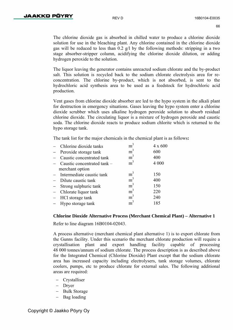
REV D 16B0104-E0035 66
Copyright © Jaakko Pöyry Oy
The chlorine dioxide gas is absorbed in chilled water to produce a chlorine dioxide solution for use in the bleaching plant. Any chlorine contained in the chlorine dioxide gas will be reduced to less than 0.2 g/l by the following methods: stripping in a two stage absorber-stripper column, acidifying the chlorine dioxide dilution, or adding hydrogen peroxide to the solution.
The liquor leaving the generator contains unreacted sodium chlorate and the by-product salt. This solution is recycled back to the sodium chlorate electrolysis area for re-concentration. The chlorine by-product, which is not absorbed, is sent to the hydrochloric acid synthesis area to be used as a feedstock for hydrochloric acid production.
Vent gases from chlorine dioxide absorber are led to the hypo system in the alkali plant for destruction in emergency situations. Gases leaving the hypo system enter a chlorine dioxide scrubber which uses alkaline hydrogen peroxide solution to absorb residual chlorine dioxide. The circulating liquor is a mixture of hydrogen peroxide and caustic soda. The chlorine dioxide reacts to produce sodium chlorite which is returned to the hypo storage tank.
The tank list for the major chemicals in the chemical plant is as follows:
− Chlorine dioxide tanks m3 4 x 600
− Peroxide storage tank m3 600 − Caustic concentrated tank m3 400 − Caustic concentrated tank –
merchant option m3 4 000
− Intermediate caustic tank m3 150 − Dilute caustic tank m3 400 − Strong sulphuric tank m3 150 − Chlorate liquor tank m3 220 − HCl storage tank m3 240 − Hypo storage tank m3 185
Chlorine Dioxide Alternative Process (Merchant Chemical Plant) – Alternative 1 Refer to line diagram 16B0104-02043.
A process alternative (merchant chemical plant alternative 1) is to export chlorate from the Gunns facility. Under this scenario the merchant chlorate production will require a crystallisation plant and export handling facility capable of processing 48 000 tonnes/annum of sodium chlorate. The process description is as described above for the Integrated Chemical (Chlorine Dioxide) Plant except that the sodium chlorate area has increased capacity including electrolysers, tank storage volumes, chlorate coolers, pumps, etc to produce chlorate for external sales. The following additional areas are required:
− Crystalliser − Dryer − Bulk Storage − Bag loading

REV D 16B0104-E0035 67
Copyright © Jaakko Pöyry Oy
The process for the additional areas of the chlorate merchant plant is described below. It can vary in specific details and equipment description due to the final vendor selection.
The sodium chlorate solution from the electrolytic cells contains some residual sodium chloride and hypochlorites which cause it to be corrosive. The solution passes through the hypochlorite destruction tank from which the solution is dosed with hydrogen peroxide (H2O2) to convert the residual hypochlorites into sodium chloride. The solution is then suitable for storage and transfer in less resistant materials such as stainless steel.
The chlorate solution flows to a crystalliser from the storage tank and produces sodium chlorate crystals in slurry form. This slurry is sent to a centrifuge to remove the majority of the remaining liquid. The sodium chlorate solution that is separated from the crystals contains sodium chloride, sulphate, sodium dichromate, sodium perchlorate and any sodium chlorate that did not crystallise. The solution is then stored in a mother liquor tank for recycle back to the electrolytic cells.
The sodium chlorate crystals, with approximately 1.5 % moisture content, leave the centrifuge and are conveyed to a fluidised bed dryer. Using hot air, the dryer evaporates the remaining moisture from the sodium chlorate crystals. Air is blown through a dryer heater before entering the dryer where i passes through the crystals. The air exhausted from the dryer is scrubbed with water in the dryer scrubber and the majority of entrained sodium chlorate crystals are dissolved into this water stream and therefore removed from the exhausted air. The scrubber solution is returned to the centrifuge, and the scrubbed air vented to atmosphere.
After the dryer the sodium chlorate crystals will be conveyed to a crystal receiving bin that temporarily stores the crystals before they are bagged in Flexible Intermediate Bulk Containers (FIBC) or in rigid ISO containers. For international transport, the sodium chlorate is packed in 1 t FIBC bulk bags or in rigid ISO containers. The bags or containers are aligned on a platform beneath the crystal receiving bin and a “funnel” from the bin is completely sealed within the liner of the bag or container to prevent any crystal loss. The bags are sealed, packed into containers that are loaded onto flat bed trucks for transport to the Port at Bell Bay. Rigid containers are sealed prior to shipping on flat bed trucks. Approximately 150 bags or up to 15 containers will be filled and transported each day.
The dust in the area will be minimised through the use of good housekeeping practices. All substances that are incompatible with sodium chlorate, particularly acids and organic substances, will be stored and handled in a separate section of the facility.
Sodium chlorate has a dangerous goods classification of Class 5.1 Oxidising Substances Packaging Group II. All trucks will conform to current Commonwealth and State requirements.
All personnel handling the crystals will be appropriately trained in accordance with the site Safety Management System. These mandated steps help to reduce transportation risks and conform to standard policies and procedures across Australia.

REV D 16B0104-E0035 68
Copyright © Jaakko Pöyry Oy
Chlorine Dioxide Alternative Process (Merchant Chemical Plant) – Alternative 2 Refer to line diagram 16B0104-02040.
The second alternative (merchant chemical plant alternative 2) uses the large amount of hydrogen produced from the merchant chlorate plant to generate hydrogen peroxide both for sales for consumption within the pulp mill, and for an alternative process of generating chlorine dioxide. There will be no chlor alkali plant and hence no generation of caustic at the mill site for this alternative. The alternative method for generating chlorine dioxide uses sulphuric acid instead of hydrochloric acid, and hydrogen peroxide and comprises the following main departments:
− Caustic handling − Sulphuric acid handling − Chlorate plant − Chlorine dioxide plant − Hydrogen peroxide plant
The caustic handling plant will handle all the caustic required for the pulp mill being supplied by boat to the pulp mill wharf. The caustic would arrive by boat (approximately 5 000 tonnes) and discharge to a larger caustic tank located in the chemical plant (4 000 m3) and bunded to prevent overflows. The caustic unloading facility and unloading operations would also be subject to the special rules and regulations appropriate for caustic soda. The caustic would be unloaded by the ships pump into a pipeline which would convey the caustic up to the storage tank located in the chemical plant. The unloading operation would take approximately 12 hours to complete. A small “stripper” pump located at the wharf will pump the contents of the unloading pipeline and convey by a smaller pipeline also to the larger storage tank to ensure that the larger unloading pipeline does not contain caustic after the unloading operation. The smaller pipeline will be emptied to the caustic storage tank by flushing through with water. Both pipelines will be continuously welded stainless steel pipes running above ground on an easement from the wharf to the storage tank. The lines will have a valving arrangement that will comprise non return valves, double block valves and bleed valves to ensure that the line is emptied correcting after the unloading procedure is completed. The storage tank will be fitted with level indication, high level alarm, and high level alarm which will be both indicated at the tank, control room and a separate panel located at the wharf. Strong sulphuric acid (98 %) is received by truck and off-loaded to the storage tank which will be bunded to prevent overflows, spills and tank rupture.
The chlorate plant comprises the following main department areas:
− Brine treatment − Sludge treatment − Chlorate electrolysis − Transformer – rectifier − Chlorate crystallization and storage − Hydrogen treatment

REV D 16B0104-E0035 69
Copyright © Jaakko Pöyry Oy
The raw material, either rock salt or solar salt, is treated in the brine treatment to sufficient purity for use in the chlorate process. Raw salt is received and stored in a shed measuring 90 m x 112 m. The raw salt is dissolved in a dissolver consisting of various compartments using heated water. Sodium carbonate and caustic are added in order to precipitate out calcium contained in the raw salt. The brine is heated to optimum temperature before the treatment and the precipitate is eliminated in a settler with natural precipitation of the formed sludge. The sludge is pumped to the sludge treatment department for treatment and conditioning. The settled and clarified brine is filtered in two parallel filters in order to ensure the elimination of particles and remaining suspended sludge. An ion exchange unit is used in order to eliminate the last traces of calcium and magnesium in the brine.
The chlorate electrolysis generates chlorate electrolytically in the same manner and according to the same reaction equation described above. The electrolyte, which is enriched in salt added to the electrolyte circuit, overflows to the electrolyte storage tank. The electrolysis takes place in a series of electrolytic cells fed with DC current from the transformer and rectifier department. The electrolyte circuit consists of the electrolytic cells, hydrogen-electrolyte separators, primary and secondary reaction tanks and an electrolyte cooler. The electrolyte is filtered in two parallel filters before being fed to the crystallization department. Any internal spillage of electrolyte will be collected and sent to the filtration step for recovery. The sludge from the electrolyte filtration, containing mainly iron and small amounts of chromium, is sent for sludge treatment.
The sludge treatment department ensures that there is no uncontrolled discharge of sludge from containing iron, calcium, gypsum and small amounts of chromium. After this pre-treatment both the electrolyte sludge and the brine sludge is dewatered in filter presses in order to obtain a solid cake that can be handled in a feasible way and thereafter sent to landfill in a controlled manner.
The purpose of the chlorate crystallization and storage area is to produce pure chlorate crystals in an evaporative crystallizer. Produced crystals will be stored in a bulk storage area. The amount of chlorate needed for the production of chlorine dioxide will be re-dissolved and stored as solution. Pre-heating of the electrolyte is performed with a plate type heat exchanger before it is sent to an agitated evaporative crystallizer. The condenser and the vacuum system of the crystallizer is cooled by chilled water. The chlorate slurry that is produced from the crystalliser is dehydrated on a table filter before being fed to the dryer area. The wet chlorate crystals are converted into dry sodium chlorate crystals in the dryer section. The main equipment comprises a dryer and dust scrubbers.
Hydrogen gas from the electrolytic chlorate cells contains a minor amount of chlorine that needs to be eliminated before being sent to the lime kiln as a fuel or discharged to the atmosphere. This operation is performed by two hydrogen scrubbers using alkaline solution.

REV D 16B0104-E0035 70
Copyright © Jaakko Pöyry Oy
The process for hydrogen peroxide generation is based on palladium fixed bed catalyst technology. The circulating working solution consists of a solvent mixture and ethyl anthraquinone (AQ) as active reagent-carrier of H2 and O2. The process involves the following main process steps. The catalytic hydrogenation of AQ to AQH2, is carried out in a hydrogenation reactor with catalyst and filtering arrangement. The oxidation of AQ-H2 to AQ + H2O2 with oxygen is performed in an oxidation reactor. The H2O2 is then extracted as a 30 % aqueous solution by means of an extraction column and coolers. Unwanted side reactions which occur in the hydrogenation and oxidation steps are reversed in an alumina oxide regeneration system. The resulting hydrogen peroxide will be stored in a storage tank and delivered as a 30 w% solution. The peroxide is then pumped to the chlorine dioxide reactor for the production of ClO2 and to the pulp mill for bleaching.
The chlorine dioxide production is based on using sodium chlorate as the chlorine source, hydrogen peroxide as the reduction agent and sulphuric acid as the acidifier. The chlorine dioxide will be supplied as an aqueous solution with a concentration of 10 g/l and a temperature in the chlorine dioxide storage tanks of 12 to 15 oC. The chemical reaction for the ClO2 generation with this process is as follows;
2NaC1O3 + H2O2 + H2SO4 -> 2C1O2 + Na2SO4 + O2 + 2H2
In this process the ClO2 generator acts as both a reaction vessel and a crystallizer. The gas produced by the reaction is cooled and the water vapour condensed in order to increase the partial pressure of chlorine dioxide before the entry into the ClO2 absorber. The ClO2 absorber is a two bed packed column with a built in pump sump in the bottom. The cooled reactor gas enters the ClO2 absorber under the lower packed section and chilled water enters the absorber above the top packed section. The ClO2 solution from the absorber is pumped to the ClO2 storage tanks and from there by high pressure pumps to the bleach plant. Recycled water from the off-gas scrubber also enters the scrubber between the two packed sections. The vacuum in the ClO2 system is created by vacuum pumps installed after the ClO2 absorber. The off-gas scrubber is used to reduce the ClO2 concentration in ventilation air from various sources, but mainly from the ClO2 storage tanks and any gas remaining from the ClO2 absorption. The draft for the off-gas scrubber is ensured by parallel ventilation fans. A neutral salt cake consisting of sodium sulphate is formed in the reaction. The salt cake is separated on a drum filter and after that dissolved in water and sent to the black liquor evaporation plant. A dump tank is provided which allows maintenance on the reactor without dumping the generator liquid to sewer.
Effluent Disposal Two sumps will be provided in the chemical plant for collection of effluent.
Equipment wash water and contaminated effluents from farm bund areas will be sent to a trench system and collected in alkaline and acid sumps. Effluents will be transferred by the alkaline and acid sump pumps to the alkaline and acid neutralisation tanks for a rapid pH neutralisation and discharge to the effluent treatment plant.
REV D 16B0104-E0035 71
Copyright © Jaakko Pöyry Oy
The plant effluent will consist of
− Chlor-alkali plant scrubber blow down, containing sodium chloride − Chlorine dioxide plant tail gas scrubber, containing sodium bisulphite − Cooling tower blow down, containing dissolved solids in the mill water − Ion exchange regeneration effluent both from chlor alkali plant ion exchangers and
demineralised water treatment plant, containing regeneration hydrochloric acid, and regeneration caustic and in addition the dissolved salts removed from mill water in demineralisation
− Brine clarification sludge, containing precipitated calcium carbonate and magnesium hydroxide in sodium chloride solution
− Wasted brine filtration pre-coat material, anthracite
Chilled Water System A chilled water system provides chilled water for the production of chlorine dioxide. The water chiller will be either an absorption type unit which uses steam and a circulation fluid to produce chilled water or a mechanical type.
Oxygen Plant The separation of oxygen and nitrogen from air is based on the cryogenic process. Air stream is processed through compression/purification units. The purified air passes through an air separation module containing a rectification column with condenser, heat exchanger and expansion turbine. Liquefied oxygen is collected in a storage tank followed by an oxygen vaporiser. The produced nitrogen is used as a safety gas in the chemical plant.
Purchased Chemicals The storing and handling systems for purchased sodium hydroxide, hydrogen peroxide, sulphuric acid, magnesium sulphate and talc are included in the chemicals preparation plant.
Caustic Soda
There will always be a need for the purchase of caustic soda to meet the total pulp mill requirements. In the case of an integrated chemical plant the caustic requirements amount to approximately 15 t/d mill (as 100% caustic) and can be supplied by trucks from Hobart. The sodium hydroxide (46 %) is off-loaded from trucks to the concentrated caustic storage tank. The concentrated caustic and the 32 % solution from the alkali plant is diluted to 10-15 % and pumped via the dilution tank to the millIn the merchant chemical plant alternative 2, all caustic to the mill (approximately 90 t/d as 100 % caustic) will need to be imported. The volume is such that the importation by road is impractical and therefore consideration has been made to import the caustic by ship to the pulp mill wharf. The method used for this procedure is discussed in the section on merchant chemical plant alternative 2.

REV D 16B0104-E0035 72
Copyright © Jaakko Pöyry Oy
Sulphuric Acid
Strong sulphuric acid (98 %) is received by truck and off-loaded to the storage tank. The tank will be bunded to prevent overflows and tank rupture. The storage tank will be fitted with level indication, high level alarm, and high level alarm which will be both indicated at the tank and in the control room. The unloading pump will be hard-wired with the tank level to prevent overfilling.
The acid is pumped to the chemical plant and pulp mill.
Hydrogen Peroxide
Hydrogen peroxide (59.5 %) is received by truck and off-loaded to the storage tank. The tank will be bunded to prevent overflows and tank rupture. The storage tank will be fitted with level indication, high level alarm, and high level alarm which will be both indicated at the tank and in the control room. The unloading pump will be hard-wired with the tank level to prevent overfilling. The peroxide is pumped to the pump tank located in bleaching plant. From the pump tank hydrogen peroxide is led to the EOP stage after dilution to 10 %.
Magnesium Sulphate
Magnesium sulphate powder will be delivered by trucks in bulk form and blown to the storage silo. MgSO4 is taken out at the bottom of the silo with a measuring screw and fed to the mixing tank where powder is dissolved with warm water to produce a solution of about 150 g MgSO4/l. Magnesium sulphate solution will overflow to a small compartment inside the mixing tank and pumped from there directly to consumption.
Depending on the bleaching sequence, magnesium sulphate may not be needed in the bleaching plant.
Talc
Talc is delivered by trucks in bulk form and blown to the storage silo. Talc is taken out at the bottom of the silo with a measuring screw and fed to the mixing tank where powder is dissolved with warm water to produce a solution.
Talc is used for pitch control in the bleach plant.
3.8.4 Evaporation
General The evaporation plant consists of a seven-effect evaporation train, equipment for increasing the final dry solids content of firing liquor, a stripper column and tank farm.

REV D 16B0104-E0035 73
Copyright © Jaakko Pöyry Oy
The main criteria for selecting the evaporation plant design concept are the following:
− Good steam economy achieved with seven-effect system. − High dry solids content of the firing liquor for good combustion and to minimise
emissions from recovery boiler. − High availability promoted by ash collection to strong black liquor. − Possibility of handling biosludge and salt cake from the ClO2 plant. − Reliable combustion of CNCG gas achieved by implementing the optional methanol
liquefaction.
The evaporation plant also needs to be able to process softwood. Therefore the following additions have been made to the hardwood configuration:
− Soap collection system − Red oil separation changed to turpentine decanting − Intermediate liquor tank
Refer to process orientation diagram 16B0104-02034.
Process Description The evaporator train consists of a concentrator unit running with MP steam and evaporation effects 1-7 running with LP steam. All the units have forced circulation pumps, which are also used to transfer the liquor to the following effect. The stripper is connected to receive the steam from effect 1.
The weak black liquor is introduced into the evaporation train and evaporated towards the first effect. A stream from effect 2 is diverted for the boiler mixing tank to pick up the boiler ash. This flow returns back to effect 1. The finally concentrated product liquor is flashed and pumped into pressurised firing liquor storage tank. The excess biosludge from the biological effluent treatment plant is mixed with half strong black liquor at the inlet of # 1 effect. The amount of the biosludge is about 20 BDt/d at about 12 % dry solids. This corresponds to only about 2.0 % of the total firing black liquor flow to the recovery boiler.
The firing liquor from the firing liquor tank is first led to a flash vessel for final temperature adjustment and the firing liquor is then pumped to the recovery boiler.
The secondary condensates are separated into several streams according to their purity. The most contaminated fraction is led to the stripper together with the foul condensate from the cooking plant. This system makes the reuse of secondary condensates in the process as effective as possible.
Secondary condensates are utilised at the fibre line and at the causticising plant to reduce process water consumption.
Surface condensers may be split to two sections; the first part of the condensers are used for producing warm or hot water from mill water, needed in the process and the second part is cooled with cooling water circulated through cooling tower.

REV D 16B0104-E0035 74
Copyright © Jaakko Pöyry Oy
The CNCG gases from the firing liquor tank, stripping column, surface condenser and foul condensate tank are collected, cooled and evacuated to the recovery boiler plant and to the NCG boilers for incineration. DNCG gases are collected from various sources, treated in a cooling scrubber and sent by a fan to the recovery boiler.
Methanol is liquefied and stored for burning in the lime kiln or recovery boiler. Turpentine from the decanting tank is pumped periodically to be burned in the recovery boiler CNCG burner or in the NCG boilers.
The stripper gases are taken to a methanol column, where the methanol concentration is increased. Live steam is fed to the bottom of the column. Concentrated methanol vapour is condensed in a cooler and the liquid methanol is collected in a methanol tank. Condensate from the methanol column is led to a turpentine decanter. Turpentine is led to the methanol tank. Inert gases from the methanol plant are led to the CNCG collection system.
After the softwood run campaign is over the soap in weak and intermediate liquor tanks is transferred to soap collection tanks. The contents of the soap collection tanks are continuously pumped at low flow rate with a displacement pump to be mixed with as fired black liquor before the liquor ring.
During operations the evaporation plant liquor side heating surfaces can be subjected to scaling by different sources such as: calcium carbonate, sodium carbonate, fiber, soap in the case of softwood operations, and aluminium or silicate. The plant concept has considered these factors. For the processing of softwood a soap removal system is included. Black liquor is filtered before it leaves the fiberline to remove any fiber. Calcium carbonate scaling is prevented by controlling the black liquor residual alkali at the cooking plant. A calcium deactivation system is not required under these circumstances. Sodium carbonate scale is also prevented by ensuring that the critical concentration value for the precipitating salts is not exceeded within the evaporator units. The evaporator units which are most vulnerable to sodium carbonate scaling are the 2nd and 3rd effects which will be equipped with on the run washing facilities.
The evaporation plant comprises the following tank farm:
− Weak black liquor storage tanks m3 2 x 6 500
− Spill liquor tank m3 4 500 − Intermediate liquor tank m3 4 500 − Soap collection tanks m3 2 x 1000 − Strong black liquor tank m3 1 000 − Firing liquor tank m3 1 000 − Foul condensate tank m3 400 − Secondary condensate tanks m3 2 x 200 − Warm water tank m3 300

REV D 16B0104-E0035 75
Copyright © Jaakko Pöyry Oy
3.8.5 Recovery Boiler
General The recovery boiler plant consists of the recovery boiler with auxiliaries, electrostatic precipitator, thermal feedwater treatment, mill condensate treatment and chemical after-dosing system.
The main criteria for selecting the recovery boiler design concept are the following:
− Steam values 104 bar(a), 505°C for high power generation rate. − Low sulphur emissions through high dry solids black liquor combustion. − Low particle emissions through dust removal with electrostatic precipitator with
three chambers/four fields per chamber. − Possibility of incinerating dissolving tank vent gases, methanol, turpentine, DNCG’s
and CNCG’s in recovery boiler. − Low NOx emissions through combustion air levelling (primary, lower secondary,
higher secondary, tertiary and quaternary air; the actual specified names depend on the boiler Vendor).
Process Description Condensates from the mill are collected into the main condensate tank. The volume of the condensate tank is 110 m3. Condensates are then cleaned in a precoat filter and led forward to a 420 m3 (gross volume) feedwater tank for thermal feedwater treatment.
Refer to process orientation diagram 16B0104-02034.
Feedwater from the feedwater tank to the recovery boiler is pumped by three pumps, two of which are electrically driven and furnished with hydraulic couplings of variable speed drives and one turbine-driven. Normally, one or two electrically driven pumps are running. The turbine- driven pump is for emergency situations. A separate feedwater pump is used for power boiler.
Feedwater from the feedwater pumps is led through the economiser to the drum where water and steam are separated. Non-volatile compounds are removed from the drum by continuous blow-out. Saturated steam from the drum is led to the superheater, which is divided into several sections. There is desuperheating between each stage. Superheated steam is then finally led to the turbogenerator plant.
The floor of the recovery boiler is made of carbon steel tubes. On the front and rear walls the Sanicro 38 tube section extends onto the floor and above primary air ports. The lower furnace walls extending up to two metres above the centre line of the tertiary air ports are made of composite tubes.
Half strong or strong black liquor from the evaporation plant is led to the mixing tank. Ash from hoppers and the electrostatic precipitator is mixed and the liquor is pumped back to the evaporation plant for final evaporation. It is also possible to extract part of the ash from the circulation. Firing liquor from the evaporation plant is pumped to the liquor guns of the recovery boiler. The direct liquor preheater is used if necessary.

REV D 16B0104-E0035 76
Copyright © Jaakko Pöyry Oy
Normally, the temperature is already adjusted at the evaporation plant. A salt cake make-up system and a system for extraction of ash are included.
Smelt from the recovery boiler is led to the dissolving tank through water-cooled smelt spouts. Smelt is dissolved in weak white liquor from the causticising plant and thus green liquor is formed. Green liquor is then pumped back to the causticising plant. Weak white liquor and green liquor pipelines are frequently swapped in order to keep the lines clean. Vent gases from the dissolving tank are treated in a vent gas scrubber and led to the recovery boiler’s furnace together with secondary air.
Combustion air for the boiler is introduced with primary, secondary and tertiary air fans. All air fans are furnished with a frequency drive. All air flows are first heated with hot pressurised water recovered from the flue gas coolers, further heated with medium pressure steams MP1 and MP2 to final combustion temperature. There are automatic air port cleaners for both primary and secondary air. DNCG gases and dissolving tank vent gases are introduced into the furnace as secondary air. The recovery boiler is furnished with the necessary number of start-up and load burners. Maximum steam generation with natural gas only is approx. 50 % of MCR.
CNCG gases are incinerated in a burner located on the front wall at the secondary air level. The burner is optionally furnished with separate lances for methanol and turpentine incineration.
Flue gases from the recovery boiler are led to a three-chamber (four fields per chamber) electrostatic precipitator. The recovery boiler ESP has been designed for 40% load/chamber. Each chamber can be isolated with remote-operated dampers. After each chamber there is a flue gas fan. Flue gas fans are frequency controlled. Flue gases are finally led to a 130 m high stack. A more detailed description of the ESP design is given in Chapter 4, Environmental Considerations.
There will be an ash processing system either in the evaporation plant or in the recovery boiler area. This system removes chlorine and potassium from the precipitator ash so that chlorine level in the virgin black liquor remains under 0.2 w % and potassium level under 1.0 w-%. There are three systems available for this (two based on ash recrystallisation and one based on ash leaching). The NaCl and KCl purge from the process is directed to effluent treatment plant.
A sufficient number of sootblowers is provided to keep the heat transfer surfaces clean. Sootblowing steam is normally taken from the turbine. Alternatively, it can be taken in conventional fashion directly from the recovery boiler (after the primary superheater).
The after-dosing chemical system includes necessary pumps and tanks for injection of oxygen removal chemicals to the feedwater tank and boiler water pH control chemicals for the feedwater to the drum. The oxygen scavenger chemicals will be used to eliminate oxygen in boiler water and condensate to minimize corrosion and thus the possible damages to the equipment and process caused by corrosion. The used chemicals are those with AQIS approval for boiler water use and commercially available in Australia.

REV D 16B0104-E0035 77
Copyright © Jaakko Pöyry Oy
Continuously monitored steam and water samples are taken as follows:
− Conductivity from − demineralised water to demineralised water tank − condensates from departments to main condensate tank − condensate after condensate filter − feedwater after feedwater tank − boiler water from drum − saturated steam before superheater − superheated steam after superheater
− Silicate from − demineralised water to demineralised water tank − condensate after condensate filter − saturated steam before superheater
− pH from − condensate after condensate filter − feedwater after feedwater tank − boiler water from drum − superheated steam after superheater
− Sodium (optional) from − condensate after condensate filter
− Total organic carbon (optional) from − condensate after condensate filter
− Oxygen from − condensate from turbine condenser
Sealing water for the recovery boiler plant is produced from mill water by filtration.
The recovery boiler plant comprises the following main tanks:
− Feedwater tank m3 400
− Mill return condensate tank m3 110 − Dissolving tank m3 500 − Dump tank m3 20 − Mixing tank (boiler ash) m3 18 − Sealing water tank m3 200

REV D 16B0104-E0035 78
Copyright © Jaakko Pöyry Oy
3.8.6 Recausticising
General The recausticising process consists of green liquor filtering, lime slaking and causticising, white liquor filtering, lime mud washing and lime mud thickening.
The criteria for selecting the recausticising plant’s design concept are the following:
− Low suspended solids content in green liquor − White liquor high active alkali and low suspended solids content − Efficient lime mud washing.
Process Description Raw green liquor is pumped from the smelt dissolving tank to a raw green liquor tank. Green liquor is then pumped from the raw green liquor tank to green liquor filters. Clear green liquor received from the filters is stored in green liquor storage. Green liquor is then pumped from the green liquor storage for slaking.
Refer to process orientation diagram 16B0104-02034.
Dregs are removed from the filters to the dregs tank, from where dreg slurry is pumped to dreg filtration. The dreg filter consists of a vacuum-operated drum filter using lime mud precoat where lime mud is dewatered on the filter drum, forming a dry lime mud precoat. The dregs are washed on the filter with hot water. Scraper plates located on the outer position scrape dregs out of the drum. A dregs centrifuge system including a dilution washing system for the removal of dregs from the process will be considered as an alternative to the dregs filter.
Prior to feeding into the slaking system, the green liquor is cooled in a flash cooler. Lime is fed to the slaking system from the reburnt lime bin by a screw feeder. Lime is slaked in a slaker where lime mud particles are formed. Grits are scraped out from the slaker bottom chamber to the classifier screw, which takes the grits upwards. The grits are washed before leaving the process. Lime milk overflows from the slaker to the causticisers.
There are three causticiser vessels in series, each designed with three or two compartments. Lime milk from the last vessel is pumped forward for white liquor filtering.
White liquor filtering takes place in a pressurised disc filter. The system consists of a filter furnished with necessary number of discs, agitated lime mud slurry vessel, filtrate vessel and filtration and booster compressors with separators. Pressure difference forces the white liquor through the cake and filtering cloths inside the sectors. The white liquor then flows through the shaft channels into the filtrate vessel. Lime mud is attached to the surface of the filtering discs and hot water showers pre-wash it while rotating. Dry and pre-washed lime mud is scraped from the discs with scraper plates to the lime mud chutes and forward to the lime mud vessel. White liquor from the filtrate vessel is pumped to the white liquor tank.

REV D 16B0104-E0035 79
Copyright © Jaakko Pöyry Oy
Lime mud slurry at approx. 35 % consistency is pumped from the lime mud slurry vessel to the lime mud storage. From the storage tank, lime mud is pumped to lime mud washing and thickening. Lime mud washing and thickening take place in a disc-type lime mud filter. The lime mud, which is attached to the surface of the filtering discs, rotates with the discs and the washed and dry lime mud is scraped from the discs for conveying to the lime kiln. The separated weak wash liquor is pumped to the weak wash storage tank and forward to the recovery boiler for green liquor dilution.
DNCG gases are collected from various sources, treated in a cooling scrubber and sent by a fan to the recovery boiler as secondary air. Vent gases from the lime mud filter are led to a scrubber for dust removal.
Secondary condensate from the evaporation plant is used as the main source of water in the recausticising plant.
The recausticising plant comprises the following main tanks:
− Raw green liquor m3 4 000 − Green liquor m3 4 000 − White liquor m3 6 000 − Weak white liquor m3 4 000 − Lime mud storage m3 1 400
3.8.7 Lime Kiln
General The lime kiln plant consists of a lime kiln with flash dryer, auxiliaries, burner for natural gas (optionally for methanol, and hydrogen), and an electrostatic precipitator.
The criteria for selecting the lime kiln plant’s design concept are the following:
− Long retention time for burned lime − Limestone used as make-up − Low emissions
Process Description Refer to process orientation diagram 16B0104-02034.
The lime mud drying system with flue gas (flash drying) consists of feed end housing, lime mud feeding system, cyclone, rotary feeders and necessary ducting. Lime mud scraped from the lime mud filter drops onto the belt conveyor, which takes it to the feeding system. The feeding system conveys lime mud to the feed end. In the dryer flue gases exiting from the kiln carry lime mud through the ducting to the cyclone and hot flue gases will dry the lime mud. Dry lime mud is fed from the bottom of the cyclone into the lime kiln.
REV D 16B0104-E0035 80
Copyright © Jaakko Pöyry Oy
Flue gas cleaned from lime mud dust in the cyclone is led to the electrostatic precipitator (ESP). The lime kiln ESP has three fields. The induced draft fan located after the electrostatic precipitator leads the flue gases to the stack. Dry dust separated from flue gas is fed back into the kiln.
The lime kiln is a horizontal cylinder sloping towards the firing zone. The kiln is carried by supports and rotated with a driving mechanism. The firing and heating zones have a two-layer brick lining, against which the kiln shell is insulated with a brick bed and a firebrick bed is the inner layer of the kiln.
Lime mud calcinates in the kiln, and the formed burnt lime is conveyed towards the firing hood of the kiln. The energy needed for lime calcination is produced by feeding and burning natural gas in the lime kiln. It is also optionally possible to burn liquefied methanol. Lime is removed from the kiln through a cooler where heat contained in the kiln product is recuperated to the secondary air. Lime leaving the cooler is separated into fine and coarse material. The small particles drop directly onto the hot lime conveyor, while big particles are taken through the crusher onto the same conveyor. Burnt lime is conveyed by bucket elevators and conveyors to the lime bin. The lime bin storage capacity is for two days. The selected size of the lime bin is 1 600 m3.
The make-up limestone is transported to the mill and it is loaded with a front loader to a hopper. The limestone will be delivered in crushed form to the mill and lifted to the limestone bin by an elevator. Alternatively there is a lime silo for make-up lime. Make-up lime is transported to the mill and loaded with a front loader to a hopper. The separate feed system of make-up lime to slaker means it can be mixed at desired ratio.
3.8.8 Turbogenerator
General
The power plant will feature a turbo-generator and the necessary auxiliary facilities. Whether one or two turbo-generators will be installed is still under discussion with the vendors.
The selected concept for the turbogenerator plant is the following:
− Sufficient throughput in turbine in order to cover peaks in the production rates. − Maximising the power generation by sliding extraction.
Process Description Refer to process orientation diagram 16B0104-02034.
The plant consists of one extraction-back-pressure turbogenerator with condensing tail.
The turbine is furnished with the necessary number of uncontrolled bleeds for supply of sootblowing steam at 30 bar(a), higher medium pressure steam for recovery boiler air heating at 22 bar(a), medium pressure process steam at 10 bar(a) and 4.5 bar(a) pressure after the external control valves and surplus steam is led to the condensing tail.

REV D 16B0104-E0035 81
Copyright © Jaakko Pöyry Oy
There are desuperheaters to decrease the steam temperature to an appropriate value for the process.
The plant consist of by-pass stations to by-pass the turbine from the high-pressure steam net to the 10 bar(a) and 4.5 bar(a) steam nets when the turbine is out of operation. The by-pass stations are furnished with necessary desuperheaters for steam cooling.
Furthermore, the plant consists of two auxiliary condensers to serve as a back-up when the turbine is out of operation. To complement the system there will also be a vent valve to the atmosphere.
Turbine is directly coupled to a synchronous aircooled generator(s) running at 3000 RPM. The rated capacity is 190 MW.
There will be a start-up and back-up power connection to the state grid.
3.8.9 Power Boiler The power boiler will be a fluidised bed combustion boiler (BFB) suitable for 100 % biofuel firing (fines from screening, sawdust, forest residues and dewatered primary effluent sludge).
Refer to process orientation diagram 16B0104-02034.
Natural gas will be used only when the steam and power balance of the mill cannot be maintained with black liquor and biofuel firing alone. This situation will occur during start-up of the mill.
The area comprises the combined biofuel, sludge and natural gas fired boiler including auxiliary equipment like biofuel handling, ash silo with emptying device and electrostatic precipitator.
The power boiler operates in parallel with the recovery boiler and generates HP steam at the same pressure and temperature. The power boiler will control the pressure of high-pressure steam.
Combined biofuel is stored in the biofuel storage area and transferred with sludge into the boiler silo and from there the fuel mixture is fed into the boiler furnace. The primary sludge from the effluent plant is dewatered in the biofuel handling area and then conveyed to the boiler mixed with the other biofuels prior to its introduction into the furnace.
The combustion air is divided into primary air and secondary air. Both air systems have their own forced draft fan. Secondary air is heated with flue gas in an air heater. The secondary air system is also equipped with a steam coil air heater. The primary air is heated in the same way.

REV D 16B0104-E0035 82
Copyright © Jaakko Pöyry Oy
The induced draft (ID) fan located after the electrostatic precipitator creates the draft required to transfer the flue gas from the furnace to the stack outlet. By using a flue gas recirculation fan, the flue gas is recirculated from the ID fan discharge back to the primary air pressure duct after the air heater in order to control the bed temperature by lowering the oxygen content in the bed.
After the furnace the flue gases pass through the superheater and economiser and next via an electrostatic precipitator to the stack. The fly ash is collected in a storage silo. The extraction system from the silo contains both dry and wet extractions.
The bottom ash is cooled, screened and the accepted material is recycled back to the furnace via the sand silo, whereas the reject is taken into a container for dumping.
The boiler is furnished with the possibility of receiving and burning DNCG gases if the recovery boiler is out of operation or if due to any other temporary reason the gases can not be burned there.
Since the power boiler is presumed to burn only biofuels, the SO2 concentrations in the flue gas are low, normally < 100 mg/Nm3.
The NOx emissions of the power boiler derive almost exclusively from the biofuels, since the furnace temperatures in fluidised bed firing are normally less than 900°C. The normal level of NOx emission in bark and other biofuels firing is <80 mg NO2/MJ.
The TSP concentration in the flue gas is effectively controlled with an ESP below 30 mg/Nm3.
Cleaned flue gases will be discharged to the air through the 130 m high stack common with recovery boiler, but in a separate flue.
3.8.10 Malodorous Gas Handling Refer to line diagram 16B0104-02027.
Concentrated Non-condensable Gases (CNCG’s )
Concentrated non-condensable gases (CNCG’s) from the cooking plant, stripping column, evaporator surface condenser, foul condensate tank and firing liquor tank are collected into a water seal. The water seal acts like a check valve which prevents gases going backwards or possible flame propagation to continue and will also separate condensate from the gas pipes. The gases are blown with steam ejectors to incineration. The gas line from the seal tank and the line from the stripper will be provided with drop separators, flame arrestors and explosion plates.

REV D 16B0104-E0035 83
Copyright © Jaakko Pöyry Oy
Most of the CNCG’s are incinerated in the recovery boiler in a dedicated burner at the secondary air level.There will also be a CNCG incineration system comprising two flame tube boilers to serve as the first back-up. However, a portion of the CNCG’s gases are continuously led to one of the incinerators (flame tube boiler) to keep it hot and to produce sodium bisulphite for the bleach plant. CNCG’s are burned in this designated incinerator with the help of natural gas and methanol. Heat from the boiler is used to produce medium-pressure steam, which in turn is used to drive the CNCG ejectors. Flue gases are washed in the sulphur dioxide scrubber. Sulphur dioxide in the flue gases is reacting with the added sodium hydroxide forming sodium bisulphite liquor. Sodium bisulphite liquor is pumped to the bleaching plant, where it is mainly used to destroy the residual chlorine dioxide in the pulp after the D stages and in the bleach plant vent gases.
In case neither the recovery boiler nor the designated NCG incinerator is available, the second back-up will be the spare NCG incinerator .
In the event that all three incineration positions are unavailable, the gases will be diverted to the main stack into a dedicated vent gas flume. The actual need for this back-up is practically non-existent, since in this situation when both the recovery boiler and the incinerator are unavailable, the mill has to be shut down.
During the mill shutdown and in case DNCG burning is impossible in both recovery and power boilers they can be led to both of the NCG boilers. The SO2 scrubber removes sulphur-containing gases from the flue gas stream. The situation may arise that there is an excess of sodium bisulphite. It this case it is still sent to the bleach plant and chemical plant scrubbers and sewered with the effluent from the scrubber at that point. If the sodium bisulphite remaining is left it is oxidised in the effluent treatment plant to sodium sulphate. The design of the aeration plant capacity is sufficient for this small amount.
Diluted Non-condensable Gases (DNCG) Gases collected from the fibre line and evaporation plant tanks are dried, heated and normally burned in the recovery boiler. In case the diluted gases can not be burned in the recovery boiler they will be directed to the power boiler. If the gases can not be burned in either of the boilers, they will be sent to both of the NCG incinerators for destruction.
The NCG boiler will also be used to burn DNCG gases from the black liquor storage tanks in the brown stock and evaporation area, and storage tanks in the causticising plant during shutdown periods. This will minimise the odour impacts of the mill during shutdowns.

REV D 16B0104-E0035 84
Copyright © Jaakko Pöyry Oy
3.8.11 Compressed Air Plant A compressed air plant serving the instrument and mill air needs will be located on the ground floor of the turbine house.
The compressed air is produced with four parallel compressors, of which two are normally in operation, one (or two) starts for peak consumption and one is a spare.
The compressed air is dried with air driers and led to two parallel receivers, one for instrument air and the other for mill air. The quality of the instrument air and mill air is the same; the only difference is in pressure. When the pressure in the instrument air system starts to decrease, a control valve limits the flow to the mill air system granting a constant and continuous pressure for the instrument air system.
Mill air is used for maintenance equipment, cleaning and some contingent purposes.
3.8.12 Mill Water Treatment and Cooling Towers
Water Quality The raw water to the mill will be delivered from Trevallyn Dam, some 40 km from the mill site. Water will be pumped to a reservoir close to mill site and led by gravity to the mill water treatment plant. Based on information available from EskWater, the water quality to the treatment plant is as follows:
− Temperature oC 5 – 20 − Turbidity NTU 0 – 30 − Colour TCU 5 – 100 − Conductivity mS/m 5 – 20 − Calcium mg Ca/l 10 – 50 − Magnesium mg Mg/l 5 – 10 − Sodium mg Na/l 10 – 20 − Chlorides mg Cl/l 10 – 50 − Sulphates mg SO4/l 10 – 30 − Nitrates mg NO3/l 0 – 5 − Silica mg SiO2/l 5 – 15 − Total iron mg Fe/l 0.1 – 0.5 − Total manganese mg Mn/l 0.01 – 0.1 − COD mg O2/l 3 – 30
The target quality of the treated water, mill water, is as follows:
− Turbidity , less than NTU 1 − Total iron, less than mg Fe/l 0.05 − Total manganese, less than mg Mn/l 0.05 − COD, less than mg O2/l 4 − Colour, less than mg TCU/l 5

REV D 16B0104-E0035 85
Copyright © Jaakko Pöyry Oy
The proposal to use Ti Tree Bend sewage treatment plant as influent to the mill water treatment plant will be investigated as a possibility after the mill has started operations. Typically the parameters that define the suitability of raw water for a pulp mill water treatment plant are not met by the effluent quality from a sewage treatment plant. At this stage of the project the sewage treatment plant effluent quality is unknown. It is recommended that quality of the Ti Tree Bend sewage treatment effluent is monitored and an evaluation of the suitability for use at the pulp mill water treatment plant be made after the mill has commenced operations when all data is known and available. The crucial parameters to be monitored are: TDS, COD, colour, turbidity, temperature, alkalinity, iron, manganese, hardness, aluminium, chlorides, sulphates, nitrates, silica.
Water Consumption The preliminary water balance of the mill is presented in the MWWB, Annex III. The balance raw water consumption of the mill is estimated at 23.4 m3/ADt of bleached pulp. At the annual production of 1 100 000 ADt/a this corresponds to an average water flow of about 73.550 m3/d. The actual water demand of the mill depends on the final selection of certain process equipment and systems. The above balance demand has been defined to include all commercially available main process equipment
Department Design Criteria − As daily average m3/d 73.550 − Design factor 1.1 − Treatment plant capacity (at design production) m3/h 4 100 − Mill water storage volume m3 12 000 − Retention time with avg. consumption h 3
Description of the Water Treatment Process The water will be pumped to the reservoir close to the mill through a 35 km long pipeline from the existing Trevallyn Dam in the South Esk River. The reservoir will be built NE of the mill site to provide buffer storage in case of temporary problems in the raw water supply to the mill (e.g. power black-out or pipeline failure).
Clean storm water from the large building roofs and comparable areas, which do not feature any contamination risk, will be reclaimed to the water treatment system and used as make-up.
The water is delivered to the inlet well, from where it flows to chemical treatment by gravity. The flocculation chemical, aluminium sulphate, and pH control chemical, caustic soda are added and mixed with the water, which then flows to the flocculation chambers. At the end of flocculation, polymer may be added and the flocculated water is led to the flotation sand filters.

REV D 16B0104-E0035 86
Copyright © Jaakko Pöyry Oy
The flock is collected at the surface of the filters and scraped to a channel and led further to the effluent treatment plant or alternatively to primary sludge dewatering. Clarified water is filtered through sand filters and led to the mill water storage. Sand filters are washed with mill water, which is recovered to a wash water tank and pumped to the beginning of the process. The same wash water tank will be used for recovery of the storm water and cooling water blow down as water treatment plant inlet.
Sodium hypochlorite is occasionally added to the influent or clarified water or recovered water to prevent the growth of microbes and other aquatic organisms in the water treatment plant, and especially in the mill water basin.
Aluminium sulphate is delivered to the site at about 50 % liquid form and pumped from the storage tank to consumption. Diluted caustic soda for pH control is pumped from the chlor alkali plant to the caustic soda day tank. Polymer is delivered to the site in about 500 kg big bags and diluted at site to about 0.2 % concentration before consumption.
Sludge from the water treatment plant is led to either the effluent treatment plant or fed directly to the primary sludge dewatering and dewatered together with the primary sludge.
Mill water is pumped to consumption with two or three frequency controlled drive pumps, one or two normally in operation and one in stand-by or serving peak conditions.
Potable water will be taken from the existing potable water main of EskWater about 1 km NE of the mill.
Cooling Water The mill will have two cooling towers. The main cooling tower will serve three cooling water distribution nets; the first serving the pulping and recovery plants, the second the turbine condenser of the power plant and the third HVAC systems. The chemical plant cooling tower serves the chemical plant.
The cooling tower type, number of cells and dimensions will be defined when the final purchase negotiations with the suppliers are finished. The type can be either mechanical draft counter or crossflow cooling tower with plastic film fill.
The recycled cooling water will be screened with microscreens before leading to the cooling water basins for reuse.
The final number of loops and their capacities will be defined in the basic engineering phase, when the detailed cooling requirements are available.
Both cooling tower set will be equipped with its own conditioning chemical system. The cooling tower conditioning chemicals will be used to minimize corrosion, scaling and slime formation and hence the possible damage to the equipment and process caused by corrosion or scaling. The used chemicals are those with AQIS approval for cooling water use and commercially available in Australia

REV D 16B0104-E0035 87
Copyright © Jaakko Pöyry Oy
The cooling tower water conditioning will be made carefully to prevent damages due corrosion, scaling or microbiological growth. No odour emissions are expected from the cooling tower where the water management is properly controlled.
The closed cycle cooling water systems will be built and operated in compliance with Australian cooling tower standards and the Legionella regulations. The outputs from the cooling tower circuits are evaporation, minor drift loss and blow down. The only input to the circuit is the make-up water. The mill management plant and the required mill operational instructions, including the compliance with Legionella regulations, will be issued during the detailed engineering phase of the project and well before the mill start up. The plan will consist of the following:
− Registration of the cooling towers − Occupational Health and Safety − Risk management − Environmental management − Sampling locations in the cooling water net, basin and tower − Chemical feeding nozzles and drainage arrangements − Continuous cooling water quality measurement with conductivity meter and blow
down flow control − Laboratory testing program both in the mills’ own laboratory and in outside
accredited laboratory − Training
The cooling tower will be purchased so that it will meets and complies will all the appropriate Australian regulations.
3.8.13 Feedwater Treatment
Demineralised Water Demineralised water is produced from mill water by ion exchange. Also reverse osmosis followed with mixed bed filter can be used. The final decision between the processes will be made in the detail engineering phase.
Design Criteria The preliminary energy balances are presented in Item 3.5. Those balances indicate the make-up water need to be about 34 kg/s. The final make-up amount will depend on the selected equipment and also the final energy balance for the mill. The demineralised water consumption in the other departments is 9 kg/s. The demineralised plant design capacity is as follows:
− Design continuous demin. water requirement kg/s 120 − Treatment stream capacity kg/s 2 x 75
− Treatment capacity Eqv/cycle 19 000 Demineralised water quality − Sodium + potassium, less than g/m3 20 − Silica, less than g/m3 5

REV D 16B0104-E0035 88
Copyright © Jaakko Pöyry Oy
Demineralised Water Treatment The demineralisation consists of two steams; anion and cation exchangers or alternatively seven to eight RO streams followed with two mixed bed filters. The streams can be operated in parallel. The exchangers are regenerated with caustic soda and hydrochloric or sulphuric acid. The regeneration effluents are mixed in a neutralisation tank for pre-neutralisation and led to the effluent treatment plant.
The chemicals for regeneration are delivered from the chemical plant to the day tanks at the demineralisation plant.
Demineralised water will be used as make-up water mainly in the boiler house. In addition, smaller amounts will be needed for chemical production; chlorine dioxide and alkali plant, and filling of the closed-loop cooling circulation systems, as well as in laboratories.
The main tanks are:
− Demineralised water tank m3 1 100
− Neutralisation tank m3 120
3.8.14 Effluent Treatment Plant Refer to line diagram 16B0104-02026.
Raw Effluent Loads
As the result of the BAT level in-plant control measures described in Item 3.8 and summarised in Chapter 4 below, the raw effluent loads of the mill per tonne of pulp will fall below the limits contained in the “Emission Limit Guidelines” and the international effluent standards.
The average and design raw effluent loads at the maximum production of 1 100 000 ADt/a are estimated as follows:
TABLE 3-31 The Average and Design Raw Effluent Loads
Parameter Average from Process Design, including effluent from chip mill and storm water
Effluent flow, m3/d 63 770 94 690 TSS, kg/d 41 790 58 760 BOD5, kg/d 49 128 66 280 COD, kg/d 143 172 196 080 AOX, kg/d 1 453 1 615 TDS, kg/d 211 792 285 880 Colour, kg/d 31 429 50 000 Chlorate, kg/d 4 756 5 285

REV D 16B0104-E0035 89
Copyright © Jaakko Pöyry Oy
Parameter Units Value Acute toxicity LC50/EC50 a Chronic toxicity EC50 b 2,3,7,8-TCDD pg/L 10 2,3,7,8-TCDF pg/L 30 Chlorate c,d mg/L 10 Trihalomethanes including chloroform d Oil and grease No visible contamination
Design Criteria Target Process Effluent Loads.
The “Emission Limit Guidelines” define the primary design targets of the process effluent treatment plant. In addition, the international BAT guidelines, like the BAT guidelines of the European Union and the New Source Performance Standards of the USEPA, should be complied with. The comparison of the “Emission Limit Guidelines”, the EU BAT guidelines, the raw effluent loads, and the required removal efficiencies to achieve the guidelines are presented as follows:
TABLE 3-32 The Comparison of the “Emission Limit Guidelines”, the EU BAT Guidelines, the Raw Effluent Loads, and the Required Removal Efficiencies to Achieve the Guidelines Parameter RPDC
Monthly average
EU annual average
Raw effluent load, average
Req’d.rem.effic. (%)
TSS, kg/ADt 2.6 0.6 – 1.5 8.4 80.5 BOD5, kg/ADt 2.1 0.3 – 1.5 12.5 86.6 COD, kg/ADt 20 8 - 23 39.2 56.1 AOX, kg/ADt 0.2 (0) - 0.25 0.49 56.8 Colour, kg/ADt 42 n/a 10 zero
The “Emission Limit Guidelines” also define, in addition to the above indicated parameters, the following treated effluent parameters. For these parameters EU has not defined the value.
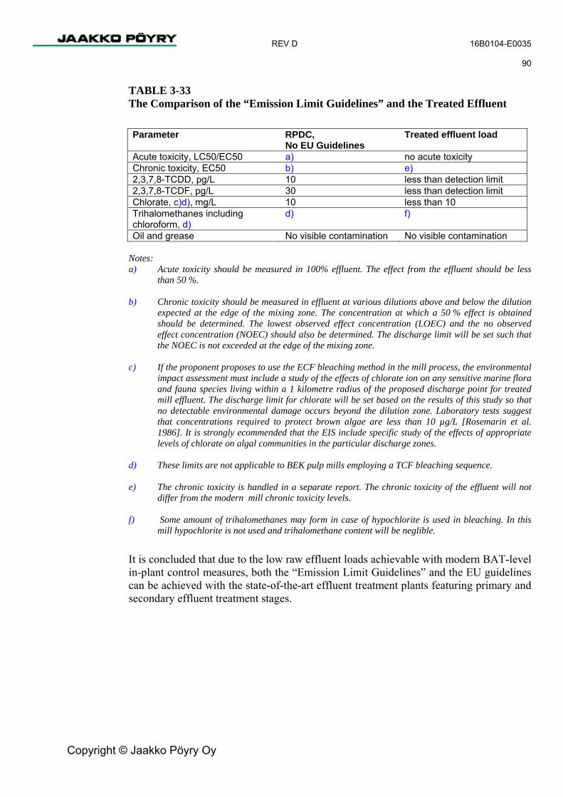
REV D 16B0104-E0035 90
Copyright © Jaakko Pöyry Oy
TABLE 3-33 The Comparison of the “Emission Limit Guidelines” and the Treated Effluent Parameter RPDC,
No EU Guidelines Treated effluent load
Acute toxicity, LC50/EC50 a) no acute toxicity Chronic toxicity, EC50 b) e) 2,3,7,8-TCDD, pg/L 10 less than detection limit 2,3,7,8-TCDF, pg/L 30 less than detection limit Chlorate, c)d), mg/L 10 less than 10 Trihalomethanes including chloroform, d)
d) f)
Oil and grease No visible contamination No visible contamination Notes: a) Acute toxicity should be measured in 100% effluent. The effect from the effluent should be less
than 50 %. b) Chronic toxicity should be measured in effluent at various dilutions above and below the dilution
expected at the edge of the mixing zone. The concentration at which a 50 % effect is obtained should be determined. The lowest observed effect concentration (LOEC) and the no observed effect concentration (NOEC) should also be determined. The discharge limit will be set such that the NOEC is not exceeded at the edge of the mixing zone.
c) If the proponent proposes to use the ECF bleaching method in the mill process, the environmental
impact assessment must include a study of the effects of chlorate ion on any sensitive marine flora and fauna species living within a 1 kilometre radius of the proposed discharge point for treated mill effluent. The discharge limit for chlorate will be set based on the results of this study so that no detectable environmental damage occurs beyond the dilution zone. Laboratory tests suggest that concentrations required to protect brown algae are less than 10 µg/L [Rosemarin et al. 1986]. It is strongly ecommended that the EIS include specific study of the effects of appropriate levels of chlorate on algal communities in the particular discharge zones.
d) These limits are not applicable to BEK pulp mills employing a TCF bleaching sequence. e) The chronic toxicity is handled in a separate report. The chronic toxicity of the effluent will not
differ from the modern mill chronic toxicity levels. f) Some amount of trihalomethanes may form in case of hypochlorite is used in bleaching. In this
mill hypochlorite is not used and trihalomethane content will be neglible.
It is concluded that due to the low raw effluent loads achievable with modern BAT-level in-plant control measures, both the “Emission Limit Guidelines” and the EU guidelines can be achieved with the state-of-the-art effluent treatment plants featuring primary and secondary effluent treatment stages.
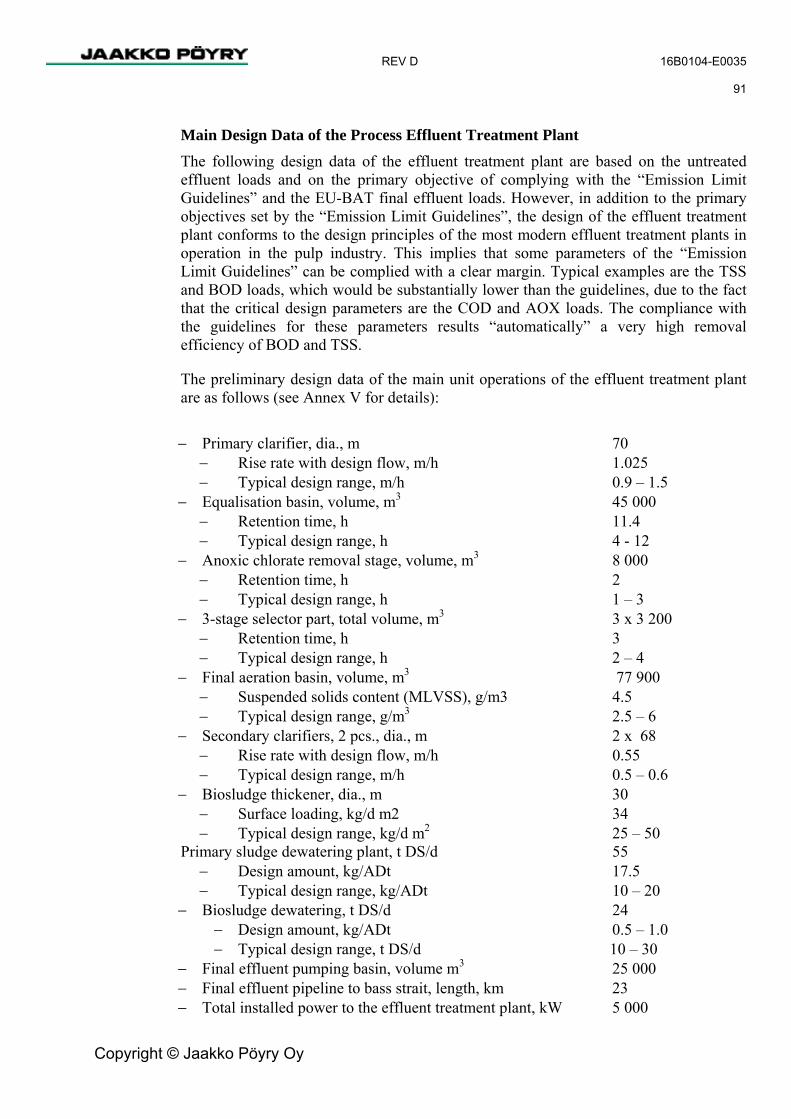
REV D 16B0104-E0035 91
Copyright © Jaakko Pöyry Oy
Main Design Data of the Process Effluent Treatment Plant The following design data of the effluent treatment plant are based on the untreated effluent loads and on the primary objective of complying with the “Emission Limit Guidelines” and the EU-BAT final effluent loads. However, in addition to the primary objectives set by the “Emission Limit Guidelines”, the design of the effluent treatment plant conforms to the design principles of the most modern effluent treatment plants in operation in the pulp industry. This implies that some parameters of the “Emission Limit Guidelines” can be complied with a clear margin. Typical examples are the TSS and BOD loads, which would be substantially lower than the guidelines, due to the fact that the critical design parameters are the COD and AOX loads. The compliance with the guidelines for these parameters results “automatically” a very high removal efficiency of BOD and TSS.
The preliminary design data of the main unit operations of the effluent treatment plant are as follows (see Annex V for details):
− Primary clarifier, dia., m 70
− Rise rate with design flow, m/h 1.025 − Typical design range, m/h 0.9 – 1.5
− Equalisation basin, volume, m3 45 000 − Retention time, h 11.4 − Typical design range, h 4 - 12
− Anoxic chlorate removal stage, volume, m3 8 000 − Retention time, h 2 − Typical design range, h 1 – 3
− 3-stage selector part, total volume, m3 3 x 3 200 − Retention time, h 3 − Typical design range, h 2 – 4
− Final aeration basin, volume, m3 77 900 − Suspended solids content (MLVSS), g/m3 4.5 − Typical design range, g/m3 2.5 – 6
− Secondary clarifiers, 2 pcs., dia., m 2 x 68 − Rise rate with design flow, m/h 0.55 − Typical design range, m/h 0.5 – 0.6
− Biosludge thickener, dia., m 30 − Surface loading, kg/d m2 34 − Typical design range, kg/d m2 25 – 50
Primary sludge dewatering plant, t DS/d 55 − Design amount, kg/ADt 17.5 − Typical design range, kg/ADt 10 – 20
− Biosludge dewatering, t DS/d 24 − Design amount, kg/ADt 0.5 – 1.0 − Typical design range, t DS/d 10 – 30
− Final effluent pumping basin, volume m3 25 000 − Final effluent pipeline to bass strait, length, km 23 − Total installed power to the effluent treatment plant, kW 5 000

REV D 16B0104-E0035 92
Copyright © Jaakko Pöyry Oy
Process Description of the Effluent Treatment Plant
Process Outline The effluent treatment plant comprises a modern primary and secondary effluent treatment facility.
Effluent entering the effluent treatment plant will have been cooled within the respective departments to about 35oC, which is an optimum temperature for the growth of the microbes in the activated sludge. An alternative is to cool the raw effluent at the ETP by using heat exchangers and a closed loop clean water cooling tower.
The primary treatment stage includes a large gravity clarifier, which removes the suspended solids from the effluent. To guarantee that the treatment is able to perform properly under the variable hydraulic loading conditions, a large emergency basin will be built to provide hydraulic resilience to the system. The primary stage also includes an equalisation basin, which reduces down the variations in the raw effluent quality. This will ensure that the operation of the subsequent biological treatment stage is as stable as possible.
The secondary treatment stage comprises an extended aeration activated sludge process integrated with an anoxic chlorate removal stage and a selector part (2-3 selectors in series). The details of the main design criteria of these unit operations are presented in Annex V.
The alternative to cool the untreated effluents is to use heat exchangers at the specific mill departments. The priority in this case is to recover heat to the process from the mill effluent. The remaining heat from the effluent is then transferred to cooling water and then cooled in the cooling tower. A second alternative is to have a separate in-direct cooling tower system at the effluent treatment plant to cool the effluents. In this alternative the effluent is cooled by circulating cooling water which is then pumped to a cooling tower. These alternatives are being kept open in order to make an economical comparison for the cooling system to be used. In none of the alternatives would the effluent be in direct contact with the atmosphere.
Pre-treatment and Primary Treatment
Effluent is discharged from process departments through flow meter, sampling devices, and pH control. The effluent is screened with non-mechanical (fixed with no moving parts) and mechanical screens and led to inlet chamber of the primary clarifier. Overflow from the inlet chamber is led to the emergency basin. Primary sludge settling at the bottom of the clarifier is pumped to the sludge dewatering plant.
The clarified effluent from the primary clarifier is led to an agitated equalisation basin. The first section of the equalisation basin consists of a neutralisation zone to adjust the effluent pH in order to have optimum conditions for the biological process. From the equalisation basin the effluent is pumped the secondary treatment stage.

REV D 16B0104-E0035 93
Copyright © Jaakko Pöyry Oy
Emergency Basin The emergency basin will be used in exceptional cases to protect the biological treatment against shock loads such as high temperature, high COD load, high TSS, high TDS, and minor effluent treatment plant equipment failure. Under normal mill operating conditions the equalisation basin will balance the effluent quality variations. In order to evaluate the need to use the emergency basin, the effluent quality from each department and the effluent quality to the effluent treatment plant is continuously monitored for TSS, pH, conductivity, and temperature. If the effluent quality entering the effluent treatment plant exceeds biological treatment plant requirement parameters it will be led to the emergency basin either partially or totally according to the situation.
The contained effluent in the emergency basin will then be pumped back under flow controlled conditions to the effluent treatment plant as soon as treatment plant parameters allow. There are reservations in the effluent treatment plant for storm water treatment and also for the difference between average and design flow for this to occur.
The emergency basin retention time of 25 hours is sufficient time for minor maintenance or repair work at the effluent treatment plant to be performed if required. The mill operating target and procedure is to keep emergency basin empty and use it only in exceptional conditions. Major maintenance work will be performed during the planned mill annual shut down which occurs once per year. Some effluent can be collected to the emergency basin to ensure continuous feed and maintain a good quality biomass for the mill start-up.
The emergency basin will also be used to feed storm water to the effluent treatment plant on occasions if the storm water is contaminated. The emergency basin will also be used as a buffer for storm water in order to minimize the effluent quality changes at the inlet to biological treatment. The content of contaminants in storm water is expected to be much lower then the untreated effluent, although it will still need to be treated.
Secondary Treatment The secondary treatment comprises the anoxic chlorate removal stage, the aerobic selector basins, the final aeration basin, and two secondary clarifiers. The total volume of the chlorate reactor is about 8 000 m3 and the total volume of the aeration basin is about 87 500 m3. The diameter of the secondary clarifiers is about 68 m, each.
Chlorate, which is a by-product of chlorine dioxide bleaching, is removed from the effluent in an anaerobic treatment stage, which has a hydraulic retention time of about one to three hour(s). This stage is followed by two to three aerated selector basins in series. The total volume of the selectors is about 9 600 m3 and the hydraulic retention time is about 3 to 4 hours. These basins could also feature a modern moving biological bed technology (MBB) to maximise the treatment efficiency. The volumes of the MBB reactors would be smaller than those of the selectors.

REV D 16B0104-E0035 94
Copyright © Jaakko Pöyry Oy
The design ClO3-removal efficiency (97.5 %). The ClO3-removal is carried out in an anoxic reactor, with a HRT (hydraulic retention time) of 1 to 3 hour (the actual HRT will depend on the final supplier selection). Moving bed bioreactors, MBBR, have different conditions than in anoxic selectors. The REDOX (reduction oxidation) potential in the reactor is adjusted properly to achieve the required reduction efficiency. The target is to arrange the anaerobic conditions so that chlorates can be decomposed. In addition to lowering the REDOX potential some nutrients will be released from the sludge. The latter can contribute to the improved selector and final aeration performance.
Return sludge from the secondary clarifiers (see below) is pumped continuously to the selector part of the plant. The typical return sludge ratio is about 80-100 % of the incoming effluent. The target mixed liquor volatile suspended solids (MLVSS) in aeration is about 4.5 g/l. This implies that the total amount of active biomass in the aeration basins purifying the effluent is approximately 400 000 kg.
The volume of the final aeration basin is about 77 900 m3 and the water depth about 7 - 9 m. The selectors and the final aeration basin are provided with submerged fine bubble aerators, which maintain the mixed liquor dissolved oxygen concentration at about 1.5 - 3 mg/l. Aeration air to the selectors and the final aeration basin is supplied by compressors. The total installed power to the aeration system is about 2.5-3.0 MW depending on the final equipment selection. The aerated effluent is discharged from the final aeration basin to two parallel secondary clarifiers. The activated sludge in the mixed liquor undergoes a bio-flocculation process and the biosludge is settled at the bottom of the secondary clarifiers. Most of the settled biosolids are returned back to aeration, while the excess biosolids corresponding to the net amount of microbial biomass formed as the result of BOD and COD removal is removed from the system as excess biosludge.
The effluent treatment results of a modern pulp mill effluent treatment plant are shown in Annex V, pages 9 and 10. The results indicate that close to 90 % COD reductions can be achieved in a well operated treatment plant. For the design of the effluent treatment plant the COD removal efficiency has been taken as 79 %. This lower factor has been used to make allowance for the assumption that during the first operation year the effluent load to the treatment plant will vary more than in the following years and will have an effect on the treatment results. The design basis is such that the effluent treatment plant will meet the required treated effluent parameters already in the first year of operation.
The clarifier effluent is led to the 25 000 m3 surge basin from where it is pumped to Bass Strait.

REV D 16B0104-E0035 95
Copyright © Jaakko Pöyry Oy
Sludge Treatment The excess biosludge is pumped to a sludge thickener and from there to the evaporation plant for further handling. Alternatively the thickener can be located under a secondary clarifier and no pumping is then required. The bottom and floating sludge from primary clarifier are pumped to a tank and further to a storage tank in the sludge dewatering plant at the biofuel storage area close to the power boiler. Sludge dewatering consists of two dewatering lines, each provided with the pre-dewatering equipment, screw press and polymer dosing equipment. Dewatered sludge is conveyed to a sludge silo or alternatively to biofuel bin and from there to the power boiler for incineration. Sludge can also be withdrawn from the conveyor to a container in case the silo is out of order. The silo can as well be emptied to a container on demand.
Chemical Handling The neutralisation chemicals, sulphuric acid or hydrochloric acid and calcium oxide, as well as phosphoric acid and urea needed as nutrient and defoamer are delivered to the treatment plant with tanker cars. The nutrients are added to the biological treatment phase. Phosphoric acid is used to provide the phosphorous source and urea is used as the nitrogen source. The nutrient level in the process will be controlled by laboratory measurements and the dosage adjusted according to the results. The defoamers are pumped directly from the transport container to the aeration basin as required. Polymers are delivered to the effluent treatment and sludge dewatering in big bags and are diluted at site.
Potential Odour Sources The potential odour sources in the effluent treatment plant are the primary clarifiers, biosludge thickener, and biosludge dewatering. The odour can arise in anaerobic conditions if the pH is low. The main measures to prevent anaerobic conditions are to maintain sufficiently high pH using pH control and to maintain short retention time for the sludge in the thickener. Additionally it is possible to locate the thickener under the secondary clarifier but this action is only open to one supplier. Another measure is to temporarily use ferric compounds to fix sulphide to a stabile ferric sulphide. The biosludge tank at the sludge dewatering plant will be connected to the dilute odorous gas collection system.
Final Effluent Loads and Disposal Due to the advanced treatment process, modern in-plant effluent control measures and the preferred pulp bleaching technology, all control parameters stipulated in the “Emission Limit Guidelines”, including the final effluent colour and COD can be complied with a clear margin. The estimated average final effluent loads are as follows:

REV D 16B0104-E0035 96
Copyright © Jaakko Pöyry Oy
TABLE 3-34 The Estimated Average Final Effluent Loads Parameter kg/ADt mg/l t/d Effluent amount 20 317 n/a 63 770 TSS 0.41 20 1.3 BOD5 0.22 11 0.69 CODCr 9.4 361 23 AOX 0.14 6.8 0.44 TDS 38.5 1 896 121 Colour 10 450 31.4 Acute toxicity, LC50/EC50
none a)
Chronic toxicity, EC50 no differences to other modern pulp mills b)
2,3,7,8-TCDD, pg/L less than 10 2,3,7,8-TCDF, pg/L less than 30 Chlorate, c )d) mg/L 0.04 1.9 0.119 Trihalomethanes including chloroform
negligible negligible negligible
Oil and grease no visible con-tamination Note: a) Acute toxicity should be measured in 100 % effluent. The effect from the effluent should be less
than 50 %. b) Chronic toxicity should be measured in effluent at various dilutions above and below the dilution
expected at the edge of the mixing zone. The concentration at which a 50 % effect is obtained should be determined. The Lowest Observed Effect Concentration (LOEC) and the No Observed Effect Concentration (NOEC) should also be determined. The discharge limit will be set such that the NOEC is not exceeded at the edge of the mixing zone.
c) If the proponent proposes to use the ECF bleaching method in the mill process, the environmental
impact assessment must include a study of the effects of chlorate ion on any sensitive marine flora and fauna species living within a 1 kilometre radius of the proposed discharge point for treated mill effluent. The discharge limit for chlorate will be set based on the results of this study so that no detectable environmental damage occurs beyond the dilution zone. Laboratory tests suggest that concentrations required to protect brown algae are less than 10 µg/L [Rosemarin et al. 1986]. It is strongly recommended that the EIS include specific study of the effects of appropriate levels of chlorate on algal communities in the particular discharge zones.
d) These limits are not applicable to BEK pulp mills employing a TCF bleaching sequence.
The final effluent will also comply with all relevant acute and sub-lethal eco-toxicity and TCDD/TCDF criteria as stipulated in the “Emission Limit Guidelines”. The final effluent would be discharged to the Bass Strait with a multi-port diffuser system to achieve an initial dilution of 1 to 100 in the sea.

REV D 16B0104-E0035 97
Copyright © Jaakko Pöyry Oy
Sanitary Effluent Treatment The total amount of sanitary sewage (including canteen effluent and shower water) is estimated at about 100 m3/d. The preliminary design flow is about 20 m3/h.
Sewage will be collected in a separate sewer system from the change rooms and other sanitary facilities, offices and the canteens. The sewage will be clarified in a standard septic tank system, and pumped to the inlet of the process effluent treatment plant. Hence, the treated sewage will be discharged to the sea together with the treated process effluent.
Leachate from Landfill Effluent from the solid waste landfill will be collected and piped to the effluent treatment plant.
The leachate quality will depend greatly on the storm water intensity and amount, and how soon the landfill will be covered. The leachate from the solid waste landfill will have no effect on the final effluent discharge.
The leachate quality is estimated to be as follows.
− Temperature, oC 10 – 25 − pH 9.5 – 12 − Conductivity, mS/m 200 – 2500 − Total suspended solids, mg/l 150 – 1000 − COD, mg/l 200 – 2200 − BOD, mg/l 50 – 500 − Total phosphor, mg P/l 1 – 15 − Total nitrogen, mg N/l 5 - 30
Storm Water Treatment The storm water drains from the mill site are divided into two separate systems. Clean storm water from the large building roofs and comparable areas, which do not feature any contamination risk, will be either reclaimed to the water treatment system or, discharged directly into a storm water drain and sent to the treated effluent pumping basin for ocean discharge with the effluent. Refer to line diagram 16B0104-02025.
Storm water from other areas at the mill site, including unused land between mill departments, site roads, and process storage tank and equipment areas, will be collected into another storm water drain system and taken to a storm water clarification lagoon, in which suspended solids and floating debris is separated especially from the first flush waters. The lagoon is also provided with an oil separation equipment to safeguard that no potential (esp. from mobile equipment) oil spills are discharged into ocean discharge. In case of contamination is found by continuous conductivity measurement or oil detection instrument the storm water is pumped to effluent treatment. From the first storm water clarification lagoon the clean storm water is led to the second lagoon and further pumped to the treated effluent surge basin. In an extreme high storm, once in ten years, the second basin may overflow to the Tamar River.
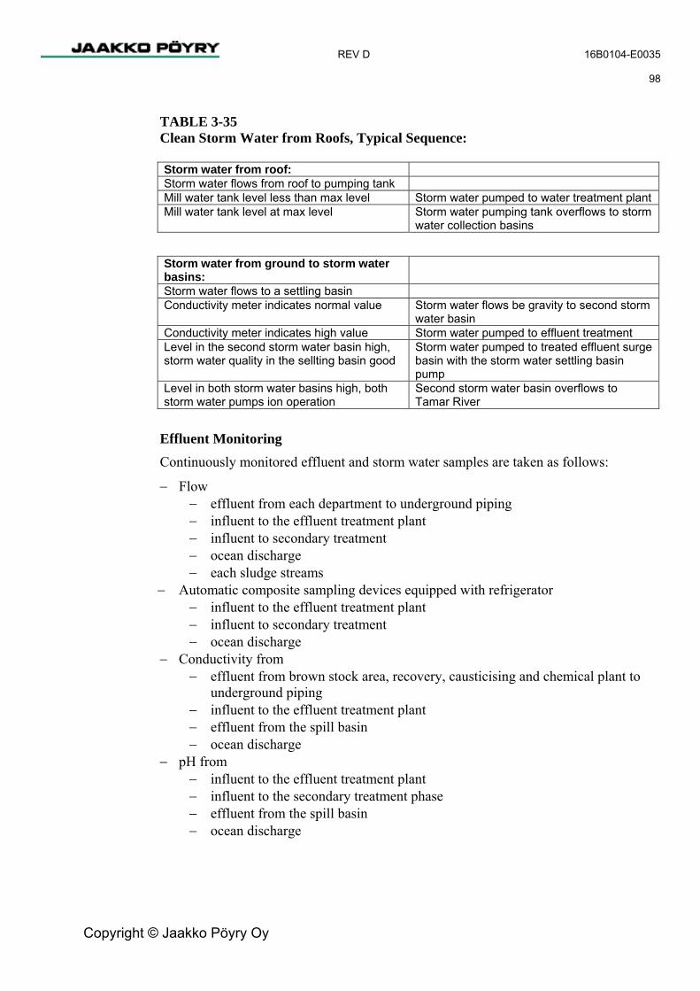
REV D 16B0104-E0035 98
Copyright © Jaakko Pöyry Oy
TABLE 3-35 Clean Storm Water from Roofs, Typical Sequence: Storm water from roof: Storm water flows from roof to pumping tank Mill water tank level less than max level Storm water pumped to water treatment plant Mill water tank level at max level Storm water pumping tank overflows to storm
water collection basins Storm water from ground to storm water basins:
Storm water flows to a settling basin Conductivity meter indicates normal value Storm water flows be gravity to second storm
water basin Conductivity meter indicates high value Storm water pumped to effluent treatment Level in the second storm water basin high, storm water quality in the sellting basin good
Storm water pumped to treated effluent surge basin with the storm water settling basin pump
Level in both storm water basins high, both storm water pumps ion operation
Second storm water basin overflows to Tamar River
Effluent Monitoring Continuously monitored effluent and storm water samples are taken as follows:
− Flow − effluent from each department to underground piping − influent to the effluent treatment plant − influent to secondary treatment − ocean discharge − each sludge streams
− Automatic composite sampling devices equipped with refrigerator − influent to the effluent treatment plant − influent to secondary treatment − ocean discharge
− Conductivity from − effluent from brown stock area, recovery, causticising and chemical plant to
underground piping − influent to the effluent treatment plant − effluent from the spill basin − ocean discharge
− pH from − influent to the effluent treatment plant − influent to the secondary treatment phase − effluent from the spill basin − ocean discharge

REV D 16B0104-E0035 99
Copyright © Jaakko Pöyry Oy
− Temperature − effluent from each department to underground piping − influent to the effluent treatment plant − influent to secondary treatment − effluent from the spill basin − ocean discharge
− TSS − effluent from brown stock, causticising, lime kiln area − influent to primary clarifier
− Oxygen − selectors, − aeration basin − ocean discharge
− Turbidity, NH4, NO3, COD, TOC, BOD, colour, PO4, − ocean discharge
Effluent treatment process and quality will be monitored on a daily basis with laboratory analysis from the composite samples, such as BOD, COD, TSS, TDS, P, N, pH, conductivity, content and in addition to composite samples some grab samples from sludge streams, mixed liquor in selectors and aeration basin, such as TSS, SVI, MLSS, MLVSS. There will be effluent quality analyses from influent to the treatment plant and ocean discharge in weekly, monthly or annual basis for such parameters as iron manganese, heavy metals and AOX, other parameters defined in the “Emission Limit Guidelines”.
3.8.15 Solid Waste Management
Non-hazardous Waste The estimated amounts, sources, and the quality of the non-hazardous and hazardous solid wastes generated at the mill are presented in Annex VII.
The total non-hazardous solid waste is estimated at about 49 000 actual t/a for a 1.1 million ADt/a mill capacity. Consequently, the landfill site of the mill will be designed for about 50 000 actual t/a on non-hazardous solid waste.
However, a substantial amount of this, or about 80 %, comprises power boiler ash, green liquor dregs, slaker sand and ESP ash from the lime kiln. These wastes could be recycled to the eucalyptus plantations as a P-K fertiliser. It is assumed that the required recycling system is planned and implemented after the mill has reached the steady state operation and the actual quality of the solid waste for this purpose is accurately known.
The amount of scrap metal and other reusable waste from the mill is estimated at about less than 100 - 5 000 t/a, depending on the maintenance and reinvestment schedules of the mill. This amount can be sold for recycling.
The non-hazardous solid wastes always disposed of to landfill comprise primarily ash from the power boiler and general household-type waste (canteens, social facilities, and site cleaning waste). This may amount to about 3 500 t/a.

REV D 16B0104-E0035 100
Copyright © Jaakko Pöyry Oy
Hazardous Waste The types and the estimated amounts of hazardous wastes generated at the mill are presented in Annex VII. The total amount is about 220 actual t/a. This comprises used lubrication and hydraulic oils, used electrical equipment and various maintenance chemicals and materials.
The hazardous wastes will be collected, packed, and stored in dedicated hazardous waste areas and sent to authorised hazardous waste contractors for final disposal.
3.9 Electrical Systems
3.9.1 Power Distribution The plant power demand depends on the wood type processed and the production rate. It is estimated to be 92 to 107 MW, of which 72 to 81 MW correspond to the pulp mill and 21 to 26 MW to the chemical plant.
Either one 190 MW steam turbine generator or 2 x 95 MW turbine generators will be installed, in the recovery island. The generator(s) will be capable of supplying the mill’s average power demand at the rated pulp production capacity. The surplus energy in normal operation will be available for sale.
The steam turbine generator will be connected to the 220 kV switchgear via one 210 MVA generator transformer in the one turbine case, or to the 33 kV switchgear via two 110 MVA generator transformers in the case of two turbines. The connection to the electricity grid will be via a 220 kV air insulated switch yard.
The energy transfer capability of the incoming 220 kV line is 150 MVA, which alone will be sufficient for pulp production at the planned capacity.
The mill 33 kV medium-voltage distribution system will be connected to 220 kV via three 63 MVA main transformers, which will be equipped with on-load tap changers. Two of the transformers will be connected to the pulp mill 33 kV bus and one to the chemical plant 33 kV bus.
The power network configuration will be based on 33 kV GIS type switchgear installed in the turbine house, drying machine and chemical plant medium-voltage electrical rooms. The distribution transformers throughout the plant will be fed from 33 kV switchgear.
The mill electrical distribution system will comply with the IEC (International Electrotechnical Commission), EN (Euro norms), and Australian electrical standards.
All foundations for the oil transformers will be equipped with an oil sump pit to prevent the leakage of oil to the mill effluent sewer system.
A construction time connection will be built from the chip mill 22 kV network.

REV D 16B0104-E0035 101
Copyright © Jaakko Pöyry Oy
3.9.2 Voltages The following voltages will be used:
TABLE 3-36 Use of Voltages Utility power connection 220 kV, 3-ph. 50 Hz
Medium-voltage distribution 33 kV, 3-ph. 50 Hz, isolated
Motors P > 630 kW 6,6 kV, 3-ph. 50 Hz, high resistance grounded
Motors P ��� kW 690 V, 3-ph. 50 Hz, solidly grounded
Motors P < 2500 kW 690 V, variable frequency drives
Lighting and socket outlets 415/240V, 50 Hz, 3-ph. solidly grounded
3.9.3 Electric Equipment
Transformers All oil immersed transformers will be installed in separate transformer bays.
Main Transformers The generator transformers and the main transformers will be oil immersed and good for outdoor installation. The 63 MVA main transformer will be equipped with an on-load tap changer.
Distribution Transformers The distribution transformers will be oil immersed good for outdoor installation and equipped with an off-load tap-changer of ± 2 x 2.5 %.
33 kV Switchgear The switchgear will be SF6-insulated, type-tested, metal-enclosed and metal-clad medium-voltage switchgear equipped with SF6 or vacuum circuit breakers and good for indoor installation.
The multifunction protection relays will be of digital type equipped with data-bus connection to power distribution control and monitoring system.
The switchboard with auxiliary equipment will be installed in a separate MV switchgear room.

REV D 16B0104-E0035 102
Copyright © Jaakko Pöyry Oy
Power Factor Correction The power factor correction is applied at 33 kV level by installing capacitor banks including 5th harmonic filters.
Power Distribution Control System (SCADA) Power distribution control and monitoring will be implemented with a dedicated supervisory control and data acquisition system providing remote control and modern diagnostics. The system will be interfaced to DCS and other systems via OPC server.
Stand-by Power
An emergency diesel generator set will be installed to supply stand-by power to essential services and critical loads. The system will be rated to 1000 kVA, 400/230 V.
6.6 kV Motor Control Centres The 6 kV MCC will be air-insulated, metal-clad type, equipped with vacuum circuit breakers.
The protection relays will be of digital type and signals for remote energy and power metering will be available.
690 V Motor Control Centres Motor control centres will be free standing switchboards with fixed contactor and circuit breaker feeder units, and intelligent motor controllers. A circuit breaker with an adjustable short circuit protection unit will be used in the incoming cubicle.
AC Motors The 6600 V and 690 V motors will be squirrel-cage induction motors with totally enclosed fan-cooled frames (IP 55). The motors will be started direct on line.
Variable Frequency Drives All variable speed drives will be AC drives with AC induction motors and PWM frequency converters and Profibus DP connections. The pulp dryer sectional drives will be equipped with a fully digital control and supervisory system.
Other Systems The access control system and fire/smoke alarm system will be implemented with a dedicated supervisory control and data acquisition system providing remote control and modern diagnostics.

REV D 16B0104-E0035 103
Copyright © Jaakko Pöyry Oy
3.9.4 Lighting Metal halide type high bay lighting fixtures will be used for the operating floor. High-pressure sodium type lighting fixtures will be used on the ground floor and in storage areas. Fluorescent type lighting fixtures will be used in electrical rooms and offices.
3.10 Process Automation and Information Management
3.10.1 General This sets out the guidelines for the applications and technology considered in the pre-engineering. The contents of the investment estimate are given in estimate-section of the report.
3.11 ERP (Enterprise Resource Planning) Concept Various systems will be established for management activities in the supply chain and administration of the mill and corporate resources. The following list of applications and their functionality is illustrative only. Exact functionality of each application depends heavily of the overall application architecture.
Applications for Sales and Distribution − Product information − Customer information − Order management and call offs − Logistics and shipping − Production allocation and rough planning − Sales planning − Transportation planning
Applications for Materials Management and Purchasing − Materials information − Materials requirements planning − Procurement planning − Materials inventory control − Supplier management − purchasing and receiving
Applications for Maintenance − Maintenance, service and resources planning and management − Work order management − Spare parts management − Manufacturing equipment assets management

REV D 16B0104-E0035 104
Copyright © Jaakko Pöyry Oy
Applications for Financial Management − Financial accounting − Managerial accounting − Accounts payable and receivable − Budgeting − Fixed assets management − Cash management and treasury − Invoicing − Credit management − Consolidation
Human Resources Management and Payroll − Personnel information − Compensation − Training management − Recruiting management − Payroll − Travel expenses
Information Management, Data Warehousing − User specific financial and operational reporting
Collaboration Applications − E-mail − Calendar − Document management
3.11.1 MES (Manufacturing Execution Systems) Concept
Production Management The mill level pulp production with warehousing and mill logistics will be handled with a production management application. The system will be an integral part of the corporate order fulfilment and commercial systems concept (in ERP concept) and will be able to work in a consistent manner with the other mill and corporate systems.
Process information Management A Process Information Management System (PIMS) is used to centrally collect, store and process, quality and other mill data and make it accessible for analysis and reporting by client users, advanced and supervisory control applications, other production applications and business systems.

REV D 16B0104-E0035 105
Copyright © Jaakko Pöyry Oy
Once collected the historical data will be available for use by trend facilities, custom displays, reports, application programs, spreadsheets, ODBC compliant databases and there will be facilities to exchange information in real time with other systems using industry standard web and XML methodologies.
Dynamic Asset Management The GUNNS ERP system described above also has a module for maintenance management. In addition to this “static” type, dynamic asset management will be applied as available from the suppliers of automation field equipment and the motor control centres. Suppliers’ diagnostic systems with standard (OPC) interface will be used in analysing the performance.
DCS (Distributed Control System) The Distributed Control System will take care of all the elementary process control functions of the plant.
The modern field buses will be used in combination with field distributed I/O, where necessary.
Motor controls are handled by the DCS with intelligent motor controller units. The intelligent motor controllers contain functionality for the diagnostics. The process control typicals will be assembled keeping in mind the local starter functionality.
MCS (Machine Control Systems) Some machinery will have controls of their own delivered with the machine packages. The Machine Control System will take care of all the elementary controls of this machinery.
The systems will be communicating with each other and other mill systems with OPC interface.
In all cases the visualisation of the controls will be realised in the DCS operator interface.
Supervisory Quality Controls Supervisory quality control systems, with various analysers, are used to measure and control variables of the pulp. The supervisory quality control systems will also provide information for manufacturing controls and of the final product.
The analysers are operating separately but providing the information to other systems with standard communication features (networks, buses or I/O). They are usually connected to the process control system of the area.

REV D 16B0104-E0035 106
Copyright © Jaakko Pöyry Oy
Bale Management, Warehouse and Logistics Systems The part processes and machinery of the baling, internal logistics and warehouse area are controlled by control systems of their own. Each system has PLC’s or other embedded systems controlling the machinery and a supervisory application controlling the lower level controllers, managing the complete process and communicating with other systems. The systems will take care of all the machinery controls and floor level functions, including measurement devices, motor and actuator controls, weigh scales, readers and printers.
The production management type communications to other systems will be arranged with an application integration system to provide application to application communication.
The process control, real time, hand shake type communications between the processes are handled using standard process control interfaces (OPC, I/O, etc.).
3.11.2 Field Automation
Transmitters and Analysers The transmitters will communicate with the Profibus DP/PA and support electronic device descriptions (EDD) for asset management purposes.
Various intelligent analysers providing several process and calculated variables will preferably be connected with industrial Ethernet or field buses.
Final Control Elements, Remote-operated Control and On-Off Valves The remote operated control and on-off valves will be equipped with pneumatic actuators and valve controllers communicating with Profibus DP/PA or controlled with solenoid valves installed in blocks communicating with industrial Ethernet or Profibus DP. Limit switches indicating the end positions will be used as required and connected to solenoid valves blocks or Profibus DP I/O.
CCTV Systems Closed Circuit TV systems (CCTV) will be used to facilitate monitoring of critical process parts and to allow the process control in the control rooms.
The mill site will be monitored with cameras located in suitable places and equipped with remote controlled moving heads and zooming facilities.
As far as possible, digital cameras using network facilities for communication will be used. A separate LAN (Local Area Network) segment will be arranged for the cameras. When using the network connected cameras, the pictures from the cameras can be viewed with web browsers throughout the connected data networks without special facilities.

REV D 16B0104-E0035 107
Copyright © Jaakko Pöyry Oy
3.11.3 Networks A network of fibre optic cables with cross connection (patch panels) possibility will be arranged between various rooms and different parts of the mill. From these network cables fibres will be reserved for systems requiring communications.
Due to maintenance, security, availability and access control reasons, the network will be split up into two physically separated and parallel networks with their own active devices: Administration Network and Production Network.
The Administration Network will provide service for general data, voice and video communications. For the voice applications a high-quality of service (QoS) is also a fundamental design goal. The voice transmission will be prioritised if network congestion exists. High availability with secured power supply infrastructure ensures the indispensable service.
The Production Network will provide data communication services for process and production control systems. The main design criterion for Production Network is high availability. This is achieved with redundant core and distribution layer switches. Access layer switches are duplicated in special cases, e.g. in control system networks. Uplinks and communication paths between devices are also made redundant. The traffic between Production Network and Administration Network is routed and filtered with access lists.
Network connections to GUNNS corporate and various partners will be through redundant external connections. Services in this network take care of the necessary routing and security measures.
Automation Networks The process information from field automation to automation and information systems will be collected with machinery embedded sensors and I/O or by cabling the signals from process transmitters and actuators to control systems using serial communication. The method of communication is based on Ethernet TCP/IP or Profibus standards. The device bus will be based on Industrial Ethernet or Profibus DP. The process transmitters and actuators with powering through signal cables will be Profibus PA. The discrete signals will be connected using ASi bus as far as possible or by using I/Os.
Motor controls will be connected to the systems with MCC intelligent communication units connected to industrial Ethernet or standard field bus. This method reduces the cost of connections and provides increased amount of information for diagnostic and asset management purposes.
3.11.4 User Interface Control places, local panels and mobile operator interface will be arranged where required for operation of machinery and various processes. Control rooms will be used where personnel protection from the environment or ergonomic and social issues so require.

REV D 16B0104-E0035 108
Copyright © Jaakko Pöyry Oy
3.11.5 Control Rooms The process controls will be centralised in the following control rooms:
1. Main control room comprising the following controls − Chip handling − Fibre line − Recovery line − Water treatment − Biofuel boiler
2. Drying machine control room
3. Integrated chemical plant (incl effluent treatment).
− Alkali plant including brine preparation − Integrated chlorine dioxide plant consisting of
− Hydrochloric acid synthesis − Sodium chlorate electrolysis − Chlorine dioxide plant
− Oxygen plant − Imported chemical handling − Effluent treatment
Administrative Functions Interface For administrative and engineering type of functions standard office type equipment will be used in the users’ regular work place.
MES User Interface The information on the state of the processes and the production line as total will be available as required by the role and tasks of each person.
Process operators’ interface is mostly the DCS operator interface. The DCS operator interface will support viewing of data of other systems, preferably by opening a browser window of the system or as a minimum OPC client capable of embedding the information on operator screens.
Computing Mill servers are providing the computing platform for various applications in administrative and production network.
Stationary and mobile work stations are providing the needed user interface for mill systems and serving local computing needs.

REV D 16B0104-E0035 109
Copyright © Jaakko Pöyry Oy
3.11.6 Storaging and Back-ups A storage area network (SAN) is established to provide data storage services for mill systems. Data will be mainly backed up and recovered over the SAN network. The servers and other computers that are not directly connected to the SAN will be backed up over the Local Area Network.
3.11.7 Communications Complete visibility between all the information sources will be supported by all the systems. The transparency of the systems allows the users to access the information anywhere within the boundaries of the network. Separate measures will be taken when the access to the information will be limited or protected.
MES Communications In order to reduce the complexity introduced to various systems by increasing the number of interfaces between systems, a separate application integration platform will be established.
This concept will allow better systems scalability and reduces costs associated with implementation, maintenance and development of existing and new systems. The systems typically provide:
− An open, expandable architecture. − Transaction based operations and scalability. − Ability to handle different data formats and as such transparency of data. − Good flexibility in handling business rules with a good adaptability to new business
functions. − Functions for regulating operations of on-line users to back-end applications.
The real time communications between process control and technical systems and between different main process areas will be carried out preferably by using OPC technology (Data access, Alarms and Events and OPC DX for control communications) or with industry standard field buses.
Voice Communications Voice over IP telephony will be applied for mill internal voice communication. The system will be using the established mill data network. Applicable servers and handsets are connected to the network for this service.
Applications with required servers, providing services for Voice Over IP (VOIP) telephony will be installed in the data network. The services will use the functionality provided by the established administrative data network active devices and cabling system.
REV D 16B0104-E0035 110
Copyright © Jaakko Pöyry Oy
3.12 Building Descriptions The description of building methods is given department by department in Annex XII (16B0104-E0008).
The final construction methods will be determined on a case by case basis during the implementation phase based on economic and technical considerations.
Space requirement for non-process facilities are described in a separate report enclosed in Annex XIII (16B0104-E0009). The report sets out the space requirements for non-process related facilities including laboratory and main control room.
3.13 HVAC Systems Design criteria of different HVAC systems are detailed in technical report 16B0104-E0018 (Annex XIV) appended to this pre-engineering report. A short summary of that report is presented below:
3.13.1 Design Criteria The main operational target of the ventilation equipment designed for different process departments is to maintain internal climatic conditions, which do not disturb production or harm the building constructions. The internal climatic conditions in the production rooms will also create sufficient working conditions for operators and maintenance personnel.
The main operational target of the HVAC equipment serving the electrical and control rooms is to maintain internal climatic conditions at a level required to meet climatic condition classes 3K1/3B1/3C1/3S1/3M1 described in standard IEC 60721-3-3. The equipment suppliers’ requirements for the climatic conditions of the electrical and automation equipment will also be taken into account. The continuous work of operators will be taken into account when designing internal climatic conditions for control rooms, programming and configuration rooms.
Room air temperature and humidity in the laboratory will be kept within the required limits.
Offices, meeting rooms, canteen and kitchen will be cooled in summer and heated in winter. Locker and wash rooms will be cooled in summer and heated in winter
Workshops will be cooled in summer and heated in winter.
The local OHS aspects will be taken into consideration when designing the process heating or cooling streams in used in the HVAC system.

REV D 16B0104-E0035 111
Copyright © Jaakko Pöyry Oy
3.13.2 Ventilation Systems for Process Rooms Generally all the closed process rooms will be ventilated by supply air units and exhaust air fans. In most cases, at least a part of supply air will be heated in winter.
Supply air will not be heated in winter if there is a high internal heat load but no moisture load in the process room and when there are no continuous working places in the process room. The boiler rooms are as an example of rooms where supply air needs not to be heated.
Exhaust air fans and air intake openings instead of supply air units will be used to ventilate closed process rooms when the supply air needs not to be directed to certain areas inside the rooms and when the supply air does not need to be heated. The chip screening building can be mentioned as an example of rooms where this ventilation system will be used.
In process rooms like the burner end of the lime kiln, the flotation filter room of raw water treatment and the pulp storages natural ventilation consisting of ridge ventilators and wall openings is considered sufficient.
All the HVAC equipment serving the process rooms will be controlled and regulated via the distributed process control system (DCS).
3.13.3 Air Conditioning Systems for Special Rooms The electrical and control rooms are cooled by air handling units circulating room air through cooling coils and mechanical filters. Overpressure in the rooms will be kept by makeup air units supplying mechanically and chemically filtered, in summer cooled and in winter heated, outdoor air to the rooms. The cable rooms will be ventilated by supply air taken from the makeup air units of the electrical rooms. Warmed air will be extracted from the cable rooms by exhaust air fans. The supply air will be mechanically filtered and cooled in summer. Supply air to the cable rooms will not be cooled if the internal heat load in the cable room is low. Offices, meeting rooms, locker and wash rooms will be ventilated by supply air units and exhaust air fans. Individual room temperatures in the offices and meeting rooms will be kept by fan coil units circulating room air through cooling coils and heating coils. Workshops will be ventilated by supply air units and exhaust air fans. The cooling effect will be generated by water chillers and distributed in the form of chilled water to the cooling coils of ventilation, air handling and fan coil units. In remote and small buildings, like the gate house, direct expansion and air cooled cooling equipment will be used. All the HVAC equipment for special rooms will be controlled and regulated via local PLCs. Important information and alarms will be transmitted to the DCS.

REV D 16B0104-E0035 112
Copyright © Jaakko Pöyry Oy
The ventilation equipment closed cooling circulation is cooled with cooling water from the main cooling tower. The cooling tower will be operated according Australian cooling tower standards and will be equipped with efficient water conditioning system and drift elimination to mitigate dispersion.
3.13.4 Heating System The heating effect needed for ventilation and to compensate heat losses through building structures in winter will partly be generated by the heat recovery exchangers installed in the exhaust air ducts of the pulp dryers. The part of heating effect exceeding the capacity of the heat recovery exchangers will be generated by steam/water heat exchangers.
The heating effect will be distributed in the form of heated water from the heat recovery and steam/water heat exchangers to the heating coils of HVAC units.

REV D 16B0104-E0035 113
Copyright © Jaakko Pöyry Oy
4 ENVIRONMENTAL CONSIDERATIONS
4.1 Emission Control Strategy The mill will use modern, proven technology and comply with relevant environmental laws and approvals. The external environmental safeguards of the mill, like the effluent treatment plant, gaseous emission control systems, solid waste management systems, noise abatement systems, will further limit any environmental impacts of the mill. Potentially hazardous emissions into the environment cannot be effectively controlled with the external safeguards alone. They can be controlled effectively only by selecting the production process conditions that will prevent or eliminate the production of potential pollutants The general objective will be to fully meet Australian regulations including but not limited to the “Emission Limit Guidelines” as well as international standards and recommendations for modern mills, such as Best Available Techniques (BAT) defined by the EU IPPC BAT reference documents for industry.
The location of the mill may present additional environmental requirements. Such requirements will be assessed and defined in the IIS.
The mill will utilise biofuel to generate its own electricity, diverting the waste from disposal. The generated electricity will be accredited renewable energy under Australian law.
4.2 Environmental Safeguards by Department
Chip Handling The environmental emissions from the existing chip mill are primarily noise and dust. They will be controlled in accordance with the best practicable technology within the framework of the existing operating permit for the facility and in accordance with relevant environmental laws and approvals. The housing around the chippers will be closed and noise reduction plates installed inside the building.
Chip screening fines and other organic rejects from wood handling are burnt in the pulp mill’s power boiler as biofuel.
No contaminated process effluents will be discharged to drain from the wood handling area at the chip mill. Chip pile leachate waters and other effluents from the existing chip mill will be pumped to the effluent treatment plant of the pulp mill.

REV D 16B0104-E0035 114
Copyright © Jaakko Pöyry Oy
Unbleached Fibre Line Area
The production technology in the unbleached fibre line will feature modern, modified continuous cooking, closed cycle brown stock washing and screening, 2-stage O2-delignification, and post-O2 washing.
The process water circuits in the unbleached fibre line will be completely closed. The pulp is washed counter-current to pulp flow from the second post-oxygen stage washer to the displacement section of the digester plant. In this way the recovery efficiency of black liquor solids will be about 99 % and the solids loss following the pulp to finalbleaching would be about 8 kg COD/ADt.
Brown stock screening and cleaning rejects comprise uncooked particles, like knots and fibre bundles (about 0.5 % of pulp) and final cleaner rejects (about 0.5 % of pulp). The uncooked particles are washed and returned to cooking, while cleaner rejects comprising primarily fines, sand and other impurities are discharged to drain, recovered in the primary clarifier and dewatered together with the rest of the primary sludge and incinerated in the power boiler.
The plant design is such that there is a small amount contaminated condensate from the cooking plant which is collected and sent to the foul condensate tank in the evaporation plant.
In normal operating conditions the department drain receives only small amounts of clean sealing and cooling water. The normal effluent amount, which flows to the effluent treatment plant, is about 0.1 m3/ADt. This effluent contains only small amounts of TSS, BOD5 and COD.
The production equipment and the drain system of the whole unbleached pulp production area is also provided with a spill containment and recovery system, which would recover all contaminated spills, equipment emptying and wash-downs to the fibre line spill liquor tank located at the digester area. The recovery system is automatically operated in accordance with the electrical conductivity, TSS and the water level in the pump sump of the department drain. A line diagram of a modern spill control system is presented in drawing 16B0104-02036. Additionally the two filtrate liquor tanks will be contained by a bunded wall with a volume corresponding to 20% of the largest volume tank in order to control overflows.

REV D 16B0104-E0035 115
Copyright © Jaakko Pöyry Oy
The unbleached fiberline is fully automated to a high degree of sophistication. The Distributed Control System (DCS) will take care of all the elementary process control functions of the plant. Variables, such as (but not limited to), flow rates to the process, temperatures, pressures, tank levels, kappa number from the cooking and oxygen delignification plants, are all measured, recorded and controlled. The process has electrical interlocking systems in place to stop the machinery in the event that critical parameters are exceeded. The automation concept is such that all tanks have various stages of alarm levels which in some cases (pulp storage towers) activate interlocking sequences to shut down the process if the safe level is exceeded. The level of automatic control is also an environmental safeguard to enable the best quality product at the optimum process conditions. The digester operation and washing system utilizes supervisory control systems to ensure the best quality, environmental and equipment performance of the process.
Modern continuous digester plants, generally, do not generate any non-condensable strong malodorous gases (CNCG’s) when cooking eucalyptus due to the use of a reboiler and indirect cooling of weak black liquor. There is no flashing of the hot black liquor which in older digester systems was a source of CNCG. However the processing of Pinus radiata results in CNCG from the turpentine decanter, turpentine storage tank, and the contaminated condensate tank. These CNCG gases that are generated, will be collected and incinerated in the odour abatement system of the mill. The dilute malodorous gases (DNCG’s) from various equipment and tank vents of the unbleached fibre line will be collected and burnt as part of the tertiary or secondary air of the recovery boiler.
Effluent from the area is continuously monitored as follows:
− Flow − Conductivity − Temperature − TSS
Bleach Plant
The final bleaching of pulp to target brightness of 90+ ISO is based on a modern elemental chlorine-free (ECF) sequence, like Do-EOP-D1-D2. The bleaching yield is about 97 %.
The bleach plant would use modern washing equipment and tightly closed water circuits. The washing water at the D2-stage washer will be white water from the drying machine. Fresh hot water is used as washing water only at the EOP-stage wash press. Clean secondary condensate (A condensate) would also be used as washing water. The resulting total bleaching filtrate amount would be only about 10-16 m3/ADt.
The actual amount of bleaching filtrate will depend on the final equipment selection. The above effluent amounts cover all commercially available equipment.
REV D 16B0104-E0035 116
Copyright © Jaakko Pöyry Oy
The specific TSS, BOD5, COD loads per ton of bleached pulp and including the carry-over from oxygen delignification are about 4, 8, and 30 kg/ADt, resp. The ECF process would result in a raw effluent AOX load of about 0.5 kg/ADt.
The raw effluent is cleaned in the state-of-the-art primary and secondary effluent treatment plant to achieve the final effluent loads in full compliance with the “Emission Limit Guidelines” and international guidelines.
The bleach plant would also feature the BAT level gaseous emission control systems typical to modern bleached kraft pulp mills. In this system the ClO2 containing vents from the D-stages are collected and scrubbed with alkaline sodium sulphite water to remove the residual chlorine dioxide from the vent gases.
The gaseous emissions volume and amount from the bleach plant scrubber are contained in Annex VIII “Environmental Emissions Diagrams”.
The bleach plant is also fully automated and controlled by the DCS to the same level as the fiberline. Flow rates to the process, (including pulp, all bleaching chemicals, wash waters, filtrates), temperatures, pressures, tank levels, residual chemicals, pulp brightness and colour, are all measured, recorded and controlled. The electrical interlocking system ensures that the relevant bleach plant equipment (or relevant sections) are shut down in the event that critical parameters are exceeded. The bleached pulp storage towers have various stages of level alarms and activate interlocking sequences to shut down the process if the safe level is exceeded. The level of automatic control is also an environmental safeguard to enable the best quality product at the lowest chemical consumption.
Effluent from the area is continuously monitored as follows:
− Flow − Temperature − TSS
Bleached Pulp Cleaning and Pulp Drying
The process system in bleached pulp cleaning will be completely integrated with the white water system of pulp drying machine and no fresh water is used in pulp dilution. The cleaning reject (about 2 BDkg/ADtbl) is discharged to the process effluent drain from the last cleaner stage of the plant at about 3 % consistency. The corresponding liquid effluent amount is about 0.067 m3/ADtbl.
The pulp drying machine would be a modern airborne drying machine. The machine would feature as closed cycle water circuits as possible.
The fresh water consumption of the drying machine would be about 3.0-4.0 m3/ADt. This would comprise the wet end showers and vacuum system and pump and agitator sealing water.

REV D 16B0104-E0035 117
Copyright © Jaakko Pöyry Oy
White water from the machine would be reused countercurrent at the (D2) washing stage. The balance excess white water, on average about 0.2 m3/ADt, will be discharged to drain together with the cleaner rejects and the bleach plant filtrate for subsequent treatment in the effluent treatment plant.
The bleached cleaning and pulp drying machine are fully automated and controlled by the DCS. All flows to the process, (including pulp, steam, water, etc), temperatures, pressures, tank levels, drying profiles, are measured, recorded and controlled as well as effluent flows and relevant quality parameters.
Effluent from the area is continuously monitored as follows:
− Flow − Temperature − TSS
Chemical Plant The environmental emissions from the chemical plant comprise liquid effluents, gaseous emissions from various equipment vent and scrubber stacks, and chemical sludge from brine purification. In addition, a substantial amount of clean cooling water is recycled through a cooling tower set back to a number of indirect cooling positions in the chemical plant.
The untreated process effluent from the chemical plant to drain comprises almost exclusively pump and equipment sealing waters. According to the MWWB the total amount of floor canal effluent is about 500 kl/d, or about 0.15 kl/ADt. In normal operating conditions the effluent quality is practically the same as the sealing water quality.
The point sources of gaseous emissions comprise gas vent stacks from the chlor-alkali and integrated chlorine dioxide plants. These vents are as follows:
− Hydrogen scrubber − Hydrochloric acid gas scrubber − Chlorine dioxide scrubber Hydrogen vent (alternatively sent to the lime kiln) − Hydrogen vent to atmosphere
The gaseous emissions volume and amount from the chemical plant vents and scrubbers are contained in Annex VIII “Environmental Emissions Diagrams” and shown on the plot diagram in Annex VI “Gaseous Emissions”.
A small amount of brine purification sludge is generated at the alkali plant. This sludge contains non-hazardous inorganic salts, like calcium and magnesium sulphates and carbonates, which are impurities in the purchased common salt. The sludge will be disposed of to the process effluent drain. The estimated amount is in order of 20-50 kg/h and is totally dependent on the salt quality. The better quality salt means less impurities and therefore less sludge. The following sludge and minor effluents, containing the components, NaCl, NaClO3, CaCl2, MgCl2, CaCO3, Na2SO4, Mg(OH)2, filter aid, coagulant will be discharged to the effluent treatment plant:
REV D 16B0104-E0035 118
Copyright © Jaakko Pöyry Oy
− Reject from the sulphate removal system (nano-filtration) − Brine ion exchange effluent − Chlorate filter backwash − Salt dissolver insolubles − Brine filter cake − Clarifier filter cake
All storage and process facilities at the chemical plant will be constructed, maintained, and operated in accordance with all relevant Australian chemical safety standards. A preliminary risk assessment has been undertaken of the chemical plant facility and is included in Vol 2 of the IIS.
Sodium chlorate, will be generated and used on site in aqueous solution and, in the case of the merchant alternatives, exported from the site in solid crystal form. The handling of sodium chlorate will comply with the Dangerous Substances (Safe Handling) Act 2005, the Dangerous Substances (Safe Transport) Act 1998, and the Dangerous Goods (Road and Rail Transport) regulations 1998. A detailed hazard analysis, risk assessment and information concerning how the risks for sodium chlorate will be managed according to the dangerous substances, workplace, health and safety, electricity and gas safety legislation will be undertaken during the detailed engineering phase of the project. The sodium chlorate plant is contained in a bunded area. All spills of sodium chlorate are returned to the process. This pertains both to the base case and merchant alternatives.
Caustic soda will be generated and used on site and also an additional amount will need to be purchased to meet the total needs of the pulp mill. The caustic will be stored at site as 46 %, 32 % and 15 % solutions with all caustic tanks being bunded to prevent overflows and tank rupture. The handling of caustic soda will comply with the Dangerous Goods Act 1998, the Dangerous Goods Regulations 1998, the Australian Code of Practice for the Transport of Dangerous Goods, the Australian Standard AS3780 for the storage and handling of Corrosive Substances. A detailed hazard analysis, risk assessment and information concerning how the risks associated with caustic soda will be managed according to the dangerous substances, workplace, health and safety, electricity and gas safety legislation will be undertaken during the detailed engineering phase of the project. For the merchant chemical plant alternative 2, caustic will be delivered to the mill by ship and will comply with the Australian Maritime Safety Authority as well as the above rules and regulations stated. The process description for the unloading system for ship delivery of caustic is provided in section 3.8.3.

REV D 16B0104-E0035 119
Copyright © Jaakko Pöyry Oy
Sulphuric acid will be purchased, imported to site and stored before use in the respective areas. The handling of sulphuric acid will comply with the Dangerous Goods Act 1998, the Dangerous Goods Regulations 1998, the Australian Code of Practice for the Transport of Dangerous Goods, the Australian Standard AS3780 for the storage and handling of Corrosive Substances. The tank area will be bunded to prevent overflows and tank rupture. A detailed hazard analysis, risk assessment and information concerning how the risks associated with sulphuric acid will be managed according to the dangerous substances, workplace, health and safety, legislation will be undertaken during the detailed engineering phase of the project.
Hydrogen peroxide will be purchased and imported to site for the chemical plant base case concept. However for the merchant chemical plant alternative 2 a hydrogen peroxide plant is proposed. The handling of peroxide acid will comply with the Dangerous Goods Act 1998, the Dangerous Goods Regulations 1998, the Australian Code of Practice for the Transport of Dangerous Goods, the Australian Standard AS3780 for the storage and handling of Flammable and Combustible Liquids. A detailed hazard analysis, risk assessment and information concerning how the risks associated with hydrogen peroxide will be managed according to the dangerous substances, workplace, health and safety, legislation will be undertaken during the detailed engineering phase of the project.
Chlorine will be generated on site and used for the manufacture of hydrochloric acid which is then used for the manufacture of chlorine dioxide. There will be no storage of liquid chlorine on site. The maximum amount of chlorine gas in the system (pipes, vessels) is approximately 60 kg. This only applies to the base case system of an integrated chemical plant. In the alternative chemical plant concepts there is no chlorine gas in the system. The mill is fitted with chlorine alarms and the containment system is such that chlorine gases are taken to hypo scrubbers leaving no release to the atmosphere.
Hydrochloric acid will be stored before use in the manufacture of chlorine dioxide and in the bleach plant. Chlorine dioxide will be contained in storage tanks before use in the bleach plant. A detailed hazard analysis, risk assessment and information concerning how the risks associated with chlorine, hydrochloric acid, and chlorine dioxide will be managed according to the dangerous substances, workplace, health and safety, legislation will be undertaken during the detailed engineering phase of the project.
Oxygen will be generated and stored on site and in the case of the merchant alternative, exported from the site in liquid form. The handling liquid oxygen will comply with the Dangerous Goods Act 1998, the Dangerous Goods Regulations 1998, the Australian Code of Practice for the Transport of Dangerous Goods, the Australian Standard AS3780 for the storage and handling of Flammable and Combustible Liquids. A detailed hazard analysis, risk assessment and information concerning how the risks associated with oxygen will be managed according to the dangerous substances, workplace, health and safety, legislation will be undertaken during the detailed engineering phase of the project.

REV D 16B0104-E0035 120
Copyright © Jaakko Pöyry Oy
The chemical plant is fully automated and controlled by the DCS. All process parameters, such as, flows, temperatures, pressures, tank levels, are all measured, recorded and controlled. The chemical storage tanks have various stages of level alarms. The effluent flows and quality parameters are also monitored with staged alarm limits. Hence, the environmental risk due to overflows and spills is greatly diminished.
Effluent from the chemical plant is led with two pipelines; acid and alkaline effluent, to the effluent treatment plant neutralisation chamber, ahead of the equalisation chamber. In the event of high pH, conductivity or temperature, the effluent is led to the emergency basin instead of entering the equalisation chamber. From the emergency basin it is pumped back, under controlled conditions, to the treatment plant.
The chemical tanks will be located in bunded area, separately for acid and alkaline chemicals. The bunded volume will be about 110 % of the highest tank volume. Inside the bund there will be a pump sump from where the chemical is pumped with transformable pump to the suitable treatment, for instance back to the process, effluent treatment plant or tanker car.
If an accidental case of high amount of bleaching chemical to the effluent treatment should occur, it will be led to the emergency basin, where the chlorine based compounds can be neutralised with calcium hydroxide, caustic soda or sodium sulphite thus avoiding disturbing effects on the biological treatment.
Both effluent streams are continuously monitored as follows:
− Flow − Conductivity − pH − Temperature which will indicate any release of chemicals to the sewer system.
Evaporation Plant
The black liquor evaporation plant will be a 7-effect falling film plant, provided with parallel concentrators in the first effect. Firing black liquor concentration to recovery boiler is >80 % dry solids.
The plant has also an integrated foul condensate stripper between the 1st and 2nd effects and features a modern secondary condensate segregation system into three different qualities of condensates: “A”, “B”, and foul condensate fractions. The foul condensate stripper system cleans the foul condensate and makes the reuse of all secondary condensates in the process as effective as possible. The methanol content serves as the measure of the condensate quality. The “A” condensate is mixed with the cleaned stripped condensate and has a methanol content of less than 100 mg/l. This condensate (“A” plus stripped condensate) is recycled to the fiberline to replace water required for washing the pulp. The “B” condensate is of lower quality with a methanol content of less than 600 mg/l. The “B” condensate is recycled back to the recausticizing plant and replaces water that is normally used for washing the lime mud.

REV D 16B0104-E0035 121
Copyright © Jaakko Pöyry Oy
The foul condensate handling system includes also a methanol condensation unit. The condensed methanol is normally used as fuel in the NCG incinerator.
The evaporator plant will be provided with BAT-level CNCG and DNCG malodorous gas handling and elimination systems as well as washing liquor and spill containment and recovery systems.
Occasional spills, wash-downs, and equipment drainage will be collected and recovered to a dedicated spill liquor tank. The recovery system is automatically operated in accordance with the electrical conductivity and the water level in the pump sump of the department drain. A line diagram of a modern spill control system is presented in drawing 16B0104-02036. Additionally evaporation plant tank farm comprising, the weak black liquor tanks, spill tank, soap tanks, intermediate liquor tank, and secondary and foul condensate tanks will be contained within a bund wall with a volume corresponding to 20 % of the largest volume tank in order to contain overflows.
The operation of the evaporation plant is fully automated and is controlled from the DCS. All flows to the process, (including black liquor, steam, water, condensates, etc), temperatures, pressures, tank levels, are measured, recorded and controlled as well as effluent flows and relevant quality parameters. The tanks have various stages of alarm levels to ensure that the safe level is not exceeded.
Effluent from the area is continuously monitored as follows:
− Flow − Conductivity − pH − Temperature
Recovery Boiler The recovery boiler will be a modern, low odour type recovery boiler in which all gaseous emissions are mitigated to at least meet prescribed environmental laws and standards.
The recovery boiler will also serve as the primary incineration facility of the malodorous CNCG and DNCG gases from the fibre line and the recovery island.
The recovery boiler flue gases will be cleaned in a highly efficient 3-chamber (4 fields per chamber) electrostatic precipitator (ESP). The design dust concentration after the ESP is 30 mg/Nm3. The recovery boiler ESP has been designed for 40 % load/chamber. This means that if one chamber of the three is out of operation the mill can operate at reduced rates (approximately 80 % of the recovery boiler capacity) so that the emission limits can be met. This occurrence is rare. A more common occurrence is one of the four fields out of operation in a chamber. If this occurs the recovery boiler can still run at full load by operating with two of the ESP chambers on a higher load and the chamber with the faulty field on reduced load. When one field of an ESP chamber has a fault, it will be closed and the maintenance on the field performed during a mill shut down.

REV D 16B0104-E0035 122
Copyright © Jaakko Pöyry Oy
Dissolving and mixing tank vents will be scrubbed and used as part of the tertiary or secondary air in the recovery boiler.
An ESP ash re-crystallisation plant will also be installed to leach the ESP dust to control the accumulation of non-process elements in the tightly closed cooking chemical cycle.
The green liquor dissolving tank, located underneath the recovery boiler, will be contained within a bund wall to contain overflows. The tank also has various stages of alarm levels to ensure that the safe level is not exceeded. If overflows do occur they are recovered in the spill collection system.
BAT-level spill containment and recovery systems will also be installed and operated in the recovery boiler area. The recovery system is automatically operated in accordance with the electrical conductivity and the water level in the pump sump of the department drain. A line diagram of a modern spill control system is presented in drawing 16B0104-02036. Local and oversees standards will be taken into consideration during the detailed engineering phase.
The recovery boiler is fully automated to a high degree of sophistication and controlled by the DCS which takes care of all the elementary process functions of the plant. All flows to the process, (including concentrated black liquor, boiler feed water, airs, steam, water, condensates, etc), temperatures, pressures, boiler drum level, are measured, recorded and controlled as well as effluent flows and relevant quality parameters. The burning process is controlled to minimize the emissions from the boiler. The boiler is also equipped with CCTV’s for the bed zone burning zone and the steam drum level. Density recorders also record the black liquor concentration to ensure that it is maintained at a value to minimize emissions. The recovery boiler is equipped with electrical interlocking systems as well as emergency shut down procedures in the event that critical parameters are exceeded.
The following continuous on-line measurements for the recovery boiler flue gases will be implemented:
− SO2 emission − TRS (measured as H2S) emission − NOx emission − Opacity − Particulate emission − Oxygen content − CO measurement − Temperature measurement
Effluent from the area is continuously monitored as follows:
− Flow − Conductivity − Temperature

REV D 16B0104-E0035 123
Copyright © Jaakko Pöyry Oy
Causticising This department would feature modern causticising, white, green, and weak white liquor systems and lime mud washing, as well as, the BAT-level spill control systems.
Clean secondary condensate from the evaporation plant would be used as the main source of process water in the area.
The department would also be provided with a modern DNCG gas system. The collected gases are piped to the recovery boiler for incineration as part of secondary air.
The process effluent drain in the causticising area will be provided with a spill detection and recovery system to prevent concentrated alkaline effluents from flowing to the effluent treatment plant. The recovery system is automatically operated in accordance with the electrical conductivity and the water level in the pump sump of the department drain. A line diagram of a modern spill control system is presented in drawing 16B0104-02036. The causticising tank farm area, comprising, the green liquor storage tank, weak wash liquor storage tank, causticisers, green liquor equalising tank, and white liquor storage tank will be contained within a bund wall of volume corresponding to 20 % of the largest volume tank in order to contain overflows. The acid tank for the cleaning of the filters will be contained by a bund wall in accordance with the safety regulations.
The operation of the causticising plant is fully automated and is controlled from the DCS. All flows to the process, (including green liquor, burnt lime, water, condensates, etc), temperatures, pressures, tank levels, are measured, recorded and controlled as well as effluent flows and relevant quality parameters. All tanks have alarm levels to ensure that the safe level is not exceeded. If overflows do occur they are recovered in the spill collection and control system described above.
Effluent from the area is continuously monitored as follows:
− Flow − Conductivity − Temperature − TSS

REV D 16B0104-E0035 124
Copyright © Jaakko Pöyry Oy
Lime Kiln The lime kiln will be fired with natural gas. TRS emissions of the lime kiln are effectively controlled by efficient washing of lime mud, use of a mud flash dryer, and maintaining a high air factor and flue gas temperature. The normal TRS concentrations are well below 10 mg H2S/Nm3 .
The TSP concentrations are effectively controlled with an ESP. The design TSP concentration is 30 mg/Nm3. The lime kiln ESP has three fields. With one field out of operation the lime kiln can be operated with approximately 65% load while still meeting the emission levels. During the mill operation the lime kiln can be shut down for ESP maintenance without affecting the pulp production since there is sufficient storage of burnt lime, lime mud, and liquor to allow the time required for maintenance.
The SO2 concentrations are normally <200 mg/Nm3 because of low soluble alkali in lime mud, and because fuel oil is not normally burnt in the kiln.
NOx emission of the lime kiln is normally at the same level as in ordinary natural gas fired furnaces, or in the order of 560-850 mg NO2/DNm3. This equates to 0.4 to 0.6 kg/ADt.
Cleaned flue gases are discharged to the air through the common 130 m high recovery boiler stack, but in a separate flume.
The lime kiln is fully automated and controlled from the DCS. All flows to the process, (including lime mud, combustion air, natural gas, water, condensates, etc), temperatures, pressures, tank levels, are measured, recorded and controlled as well as effluent flows and relevant quality parameters. All mud tanks have alarm levels to ensure that the safe level is not exceeded. If overflows do occur they are contained in a bunded area.
The following continuous on-line measurements for the lime kiln flue gases will be implemented:
− SO2 emission − TRS (measured as H2S) emission − NOx emission − Opacity − Particulate emission − Oxygen content − CO measurement − Temperature measurement
Effluent from the area is continuously monitored as follows:
− Flow − Conductivity − Temperature − TSS

REV D 16B0104-E0035 125
Copyright © Jaakko Pöyry Oy
Power Boiler The power boiler will be a fluidised bed combustion boiler (BFB) suitable for 100 % biofuel firing (fines from screening, sawdust, forest residues and dewatered primary effluent sludge) in which all gaseous emissions are mitigated to at least meet prescribed environmental laws and standards. Natural gas will be used only when the steam and power balance of the mill cannot be maintained with black liquor and biofuel firing alone.
The power boiler is furnished with the possibility of receiving and burning all the DNCG gases if the recovery boiler is out of operation or if due to any other temporary reason the gases can not be burned there.
Since the power boiler is presumed to burn only biofuels, the SO2 concentrations in the flue gas are low, normally < 100 mg/Nm3.
The NOx emissions of the power boiler derive almost exclusively from the biofuels, since the furnace temperatures in fluidised bed firing are normally less than 900°C. The normal level of NOx emission in bark and biofuel firing is <80 mg NO2/MJ.
The TSP concentration in the flue gas is effectively controlled with an ESP below 30 mg/Nm3. The power boiler ESP has four fields. With one field out of operation the boiler can be operated with approximately 80 % load while still meeting the emission levels. During the mill operation the power boiler can be shut down for ESP maintenance without affecting the pulp production. The power supply to the grid under this situation is lower.
The oxygen scavenger chemicals used to eliminate oxygen in boiler water and condensate to minimize corrosion will be stored in the power plant close to the point of consumption for the chemical with minimal quantity stored on site. The area will be contained to prevent any leak to the environment of these chemicals. The handling of the chemicals will comply with all the relevant rules and regulations.
A detailed hazard analysis, risk assessment and information concerning how the risks associated with the oxygen scavenging chemicals will be managed according to the dangerous substances, workplace, health and safety, legislation will be undertaken during the detailed engineering phase of the project.
Cleaned flue gases will be discharged to the air through the 130 m high stack common with recovery boiler, but in a separate flume.
The power boiler is fully automated and controlled by the DCS. All flows to the process, (including bio-fuel, boiler feed water, combustion airs, steam, water, condensates, etc), temperatures, pressures, boiler drum level, are measured, recorded and controlled as well as effluent flows and relevant quality parameters. The burning process is controlled to minimize the emissions from the boiler. The boiler is also equipped with CCTV’s for the bed zone burning zone and the steam drum level.
REV D 16B0104-E0035 126
Copyright © Jaakko Pöyry Oy
The following continuous on-line measurements for the power boiler flue gases will be implemented:
− SO2 emission − Particulate emission − NOx emission − Opacity − Oxygen content − CO measurement − Temperature measurement
Effluent from the area is continuously monitored as follows:
− Flow − Temperature
Flame Tube Boilers The CNCG destruction unit will comprise two flame tube boilers. One of the boilers will be in normal operation continuously to produce sodium bisulphite required for the bleach plant scrubbing system.
The flame tube boilers are fully automated and controlled from the DCS. All flows to the process, temperatures, pressures, tank levels, are measured, recorded and controlled.
The following continuous on-line measurements for the flame tube boilers flue gases will be implemented:
− SO2 emission − NOx emission − Oxygen content − CO measurement − Temperature measurement
Harbour Storm water from the harbour will be collected to a trash and oil catchment well. The storm water is then pumped to the effluent treatment plant. A more detailed description is included in the harbour report.
Caustic soda will be pumped from the ship pump to the storage tank via an unloading pipeline. A small “stripper” pump, located in a bunded area at the wharf, will pump the contents of the unloading pipeline and convey by a smaller pipeline also to the larger storage tank to ensure that the larger unloading pipeline does not contain caustic after the unloading operation. The smaller pipeline will be emptied to the caustic storage tank by flushing through with water. The lines will have a valving arrangement that will comprise non return valves, double block valves and bleed valves to ensure that the line is emptied correcting after the unloading procedure is completed. The storage tank will be fitted with level indication, high level alarm, and high high level alarm which will be both indicated at the tank, control room and a separate panel located at the wharf.

REV D 16B0104-E0035 127
Copyright © Jaakko Pöyry Oy
4.3 Water Supply The fresh water supply of the mill is described in Item 3.8.12.
According to the present plans, raw water will be taken from Trevallyn Dam about 35 km from the mill site.
The off-site fresh water intake facilities are described in detail in a separate engineering report prepared by GHD. The potential environmental considerations of the proposed raw water supply system will be assessed in the IIS report.
Effluent from the area is continuously monitored as follows:
− Flow
4.4 Effluent Treatment and Disposal
4.4.1 Compliance with the “Emission Limit Guidelines”, the EU/IPPC, and Other International Guidelines The effluent loads and the effluent treatment plant are described in Item 3.8.14 above.
The proposed effluent treatment system comprising primary and secondary treatment stages, will be modern state-of-the-art technology. This technology will result in effluent loads that are in full compliance with the “Emission Limit Guidelines” and other BAT-level international guidelines.
Effluent from the area is continuously monitored for the following:
Online:
− Flow − pH − Conductivity − Temperature
Laboratory:
− TSS − Turbidity − NH4 − NO3 − COD − AOX − Chlorate − TOC − BOD − Colour − PO4
The laboratory testing will be done on a frequency determined by the regulatory requirements.

REV D 16B0104-E0035 128
Copyright © Jaakko Pöyry Oy
4.5 Air Pollution Control
4.5.1 Gaseous Emission Safeguards BAT level safeguards will be used throughout the mill to ensure low particulate and gaseous emissions both in terms of boiler and lime kiln stack emissions.
− Collection and incineration of concentrated malodorous gases and control of the resulting SO2 emissions. The strong gases can be burnt in the recovery boiler or in a separate NCG boiler. The flue gases of the latter have a high concentration of SO2 that is recovered in a scrubber.
− Diluted malodorous gases from various sources are also collected and incinerated and the resulting SO2 controlled.
− TRS emissions of the recovery boiler are mitigated by efficient combustion control, high dry solids and keeping CO low. Burning dissolving and mixing tank vent gases in the recovery boiler further reduces mill TRS emissions.
− TRS emissions of the lime kiln are mitigated by controlling the excess oxygen, by using natural gas (low-S fuel), and by controlling the residual soluble sodium in the lime mud fed to the kiln.
− The SO2 emissions from the recovery boiler are controlled by firing high dry solids. − NOx emissions from the recovery boiler are reduced by ensuring proper mixing and
division of air in the boiler. − NOx emissions from lime kiln are reduced by using LowNox burner design. − Flue gases from recovery boilers, power boiler and lime kiln are cleaned with
efficient electrostatic precipitators to mitigate dust emissions.
It is uncertain whether the NOx limits in “Emission Limit Guidelines” can be reached without implementing mitigation measures. A detailed discussion about NOx emissions are considered in the IIS. (Refer to separate report “16B0104-E0014 NOx Issues” enclosed as part of Annex XV). The mill could meet the NOx limit depending on the fuel used.
The necessary mitigation measures would mean that heavy fuel oil is burnt in the lime kiln instead of natural gas as proposed since the nitrogen content of fuel oil is significantly lower than that of natural gas.
Particulate Control
Particulate matter emitted from the lime kiln, recovery boiler, and power boiler comprises lime dust and sodium compounds (CaO, Na2SO4 and Na2CO3 particles) condensed out of the vapour phase. The TSP is non-toxic and does not cause respiratory problems in quantities at ground level.
The recovery boiler, lime kiln, and the power boiler are equipped with high efficiency electrostatic precipitators. The dimensioning principles are described in chapter 4.2.

REV D 16B0104-E0035 129
Copyright © Jaakko Pöyry Oy
Odorous Gas Control
To ensure NCG handling reliability, there is a number of process equipment capable of handling NCGs. The system was described in detail in Item 3.8.10 above.
− Recovery boiler − CNCG (main) − DNCG (main) − Methanol (spare) − Turpentine (spare)
− NCG boilers (two) − CNCG (some, spare) − DNCG (spare and during shutdown) − Methanol (main) − Turpentine (main)
− Lime kiln − Methanol (spare)
− Power boiler − DNCG (spare)
− Stack − Separate inner stack for CNCG (spare) − Separate inner stacks for DNCG (spare)
All non-condensable gases, which contain, for example, reduced sulphur compounds, will be collected from the mill’s production departments – such as tanks, and sewers – and will be burnt at high temperature, normally in the recovery boiler. An effort will be made to control also fugitive emissions from production by using enclosed structures and ventilation, where feasible.
The boiler and kiln stack height will be chosen to ensure atmospheric dispersion sufficient to meet prescribed requirements, as indicated by emission dispersion modelling.
Reduction of CO2 Emissions caused by fossil-fuels The mill has been designed to generate its own electricity from biofuel and black liquor. Both of these sources are recognised as renewable energy sources under Australian law and therefore do not contribute to the additional formation of greenhouse gases. However, the contribution of this electricity into the national grid may help displace demand for electricity from non-renewable energy sources which would contribute to the additional formation of greenhouse gases.
In addition, the lime kiln uses natural gas instead of oil to mitigate fossil CO2 generation.
The mill will be energy efficient and will produce more steam than it uses. Excess steam will be used in the condensing turbine to produce sellable energy. This energy replaces electricity generated with fossil fuels and reduces CO2 emissions from Australia.

REV D 16B0104-E0035 130
Copyright © Jaakko Pöyry Oy
The recovery boiler will generate fossil CO2 only during start-up and shutdown when start-up burners are fired. It has to be noted that this is the CO2 generated by fossil fuels and not the total generated CO2 as defined in Annex VI. In addition some auxiliary fuel will be fired during disturbance periods. Practically all the fossil fuel demand in the lime kiln is covered by natural gas usage. The mill needs to keep the NCG-boiler warm and in operation at all times. This means some natural gas usage. The total fossil CO2 generation from the pulp mill averaged over a period of one year is only 169 kgCO2/ADt, Table 4-2.
TABLE 4-2a Mill CO2 Generation with Natural Gas as Support Fuel Heat MWh/a t CO2 /a kg CO2 /ADtRecovery boiler 5 475 000 2 114 000 1 950Lime kiln 442 490 122 070 149NCG 29 950 8 100 7Total 6 449 665 2 382 675 2 275
TABLE 4-2b Mill fossil CO2 Generation with Natural Gas as Support Fuel Heat MWh/a t CO2 fossil/a kg CO2 /ADtRecovery boiler 53 265 14 685 18Lime kiln 442 490 122 070 149NCG 6 470 1 750 2Total 50 2225 138 505 169
The estimated net CO2 balance of Australia due to the mill operation is very positive as extra electricity the mill produces with bio-fuels replaces the fossil fuel generated electricity.
Assuming that the electricity generated by the pulp mill replaces electricity generated by coal and approximately 62 MW of sellable electricity during 8000h of yearly operation is generated. Each MWh will replace approximately 1 118 kg of fossil CO2. The total reduction of fossil greenhouse gas emission in Australia due to the pulp mill producing 820 000 ADt/a is 416 000 t CO2/a. (see Table 4-3).
TABLE 4-3 Reduction of CO2 Caused by Mill Operation
MWh t CO2 fossil/a kg CO2 /ADtRecovery boiler 53 265 14 685 18Lime kiln 442 490 122 070 149NCG 6 470 1 750 2Extra electricity -1 340 540 -554 450 -676Total -838 315 -415 945 -507

REV D 16B0104-E0035 131
Copyright © Jaakko Pöyry Oy
Reduction of Other Greenhouse gases Other notable greenhouse gases are methane, nitrous oxide, ozone, hydrofluorocarbons, perfluorocarbons, sulfur hexafluoride. Of these only methane and nitrous oxide are generated during combustion. Emissions of ozone, hydrofluorocarbons, perfluorocarbons, and sulfur hexafluoride are typically below detection limits. Of the total methane emissions in Australia, the contribution of methane produced during combustion is insignificant. Of total the nitrous oxide emissions in Australia, the contribution of nitrous oxide produced during combustion is also insignificant.
4.6 Solid Waste Handling The solid waste amounts generated at the mill are discussed in Item 3.8.15 and the technical details of various solid waste types have been presented in Annex VII.
The total net amount of non-hazardous solid waste generated at the mill after all feasible recovery and recycling measures is about 49 000 actual t/a. The breakdown by various waste types is as follows:
TABLE 4-4 Generation and Disposal Principles of Non-Hazardous Solid Waste Waste type Amount, (actual t/a) RemarksPower boiler ash 8 509 Fly ash to plantations, bottom ash
to landfillGreen liquor dregs 16 000 To landfill or plantationsSlaker sand 12 222 To landfill or plantationsLime kiln ESP dust 11 785 To landfill, plantations, and/or
effluent treatmentCanteen and sanitary waste, site cleaning waste
756 To landfill
To plantations Min. 5 957Max. 45 964
To landfill Min.3 309Max. 49 273
Grand total 49 273
The design and operation of the landfill site will use state-of-the-art technology. The detailed design and operation data are presented in a separate Landfill Site Plan prepared by Pitt & Sherry.
The storm and leachate water from the landfill site will be collected into a holding basin at the site and discharged to the process effluent treatment plant. No contaminated water from the landfill site is discharged to Williams Creek.

REV D 16B0104-E0035 132
Copyright © Jaakko Pöyry Oy
4.7 Noise Abatement The noise abatement measures to be implemented at the mill will comply with Australian and international noise control standards and guidelines, including those set by the “Emission Limit Guidelines”.
To achieve this target technical noise abatement guidelines will be prepared specifically for the Bell Bay Pulp Mill project and issued to all relevant machine and equipment suppliers, as well as to civil contractors already in the tendering phase of the project.
The main focus in the guidelines will be in mill areas and positions where the expected noise levels may exceed 85 dB(A).
The necessary noise abatement measures are generally divided into the following groups:
− Selection of equipment based on the guaranteed noise emission of a machine. The general target noise level is <85 dB(A).
− Use of special noise attenuation designs and noise absorbers in pipelines, valves, and equipment.
− Noise insulation of individual machineries and equipment. − Locating of noisy machinery in dedicated, noise insulated space. − Use of special types of noise absorbing or eliminating machine foundations.
Machines with a sound pressure level in excess of 95 dB(A) will generally be installed in dedicated noise insulated spaces, while machines with noise pressure levels between 85-95 dB(A) will be provided with individual noise attenuation systems to achieve the 85 dB(A) target.
The noise abatement measures to achieve the stipulated target noise levels in control rooms, offices and social facilities will be an integral part of the civil and building engineering designs.
Typical noise levels of a pulp mill are presented in Annex XI.
4.8 Mitigation of Environmental Risks
4.8.1 Preliminary Risk Identification
General The mill will be put into operation only after all the pre-start up requirements have been fulfilled. These are required to reduce any risk of a poorly managed start-up. The pre-start up requirements are extensive and include such items as:
− Detailed engineering completed with the relevant HAZOP (or similar) studies performed for start-up, shutdown, emergency and maintenance issues
− Mill operational plan in place − Mill environmental management plan in place − Mill maintenance plan in place

REV D 16B0104-E0035 133
Copyright © Jaakko Pöyry Oy
− Mill emergency plan procedures in place. − Training of the operational and maintenance personnel undertaken. − Installation and check out of all equipment according to the required design. − Emergency diesel generators and main power distribution system available. − Process control system available. − Equipment spare parts and consumables available on site. − Raw materials available on site.
Annex XVII gives the time schedule for the start-up logic in order of the different mill departments. The Mill Common Systems (Water Supply and Treatment, Compressed Air, Effluent Treatment, and Discharge, etc) are planned to be ready for operation well before the main process areas such as the Boilers, Wood handling, Drying Machine or the Fibre Line are started, in order to have them tuned and functioning correctly before the production will start. When the Water Treatment Plant is completed and the water flushing of the other subsystems is ready to start, the Effluent Treatment Plant will be ready to receive the flushing waters. The proper test run of the Effluent Treatment will not be able to start before the process areas produce contaminated water. The NCG Boilers will be started with natural gas on time to produce 12 bar steam which is needed during the construction period (i.e. steam blows etc). The complete NCG Collection System including the scrubbing system will be completed later, when the Recovery Boiler starts and the odorous gases are available for collection. However the system can be run on air before the recovery boiler is started. The Power Boiler will be started when 100 bar steam is needed. The filling of the Biofuel Storage will start some weeks earlier to be ready when the fuel is needed for the boiler. When the commissioning of the main areas is ongoing and the demand of power grows, the Turbogenerator will be put into operation. The Drying and Baling Area will be started a month in advance of the new fibre line, with purchased pulp, to be able to do the test run before the new Fibre Line produces its own pulp. The first chips will be conveyed to the digester only after all the other areas (Evaporation, Re-causticizing, Lime Kiln, Chemical Plant) have been completed, tested and tuned with water, and ready for commissioning with pulp.
The mill start-up phase is the most demanding in terms of varying production levels and hence air and water emissions. This can be due to some individual departments having to start-up and shut down during this phase. The individual departments are designed with in-plant measures such as, spill recovery systems, designated gas scrubbers, precipitators, bunded areas for tanks, odorous gas collection system, tank storage, etc, to prevent any risk of emissions. The odorous gas system will be functional to collect any gases when the mill is shut for maintenance. The emergency basin is a back up for the in-plant measures.

REV D 16B0104-E0035 134
Copyright © Jaakko Pöyry Oy
Types of Environmental Risks The types of environmental risks associated with the pulp mill operations are as follows:
− Accidental spills of process and auxiliary chemicals from the storage tanks, process equipment, and mobile equipment.
− Accidental spills of fuel oil from the back-up storage tank and mobile equipment. − Explosion risks in;
− CNCG and turpentine collection and incineration systems. − recovery boiler due to accidental feedwater leak to the smelt bed. − chlorine dioxide plant due to accidental decomposition of ClO2 in the reactor.
− Accidental spills of fibres, black liquor, and other hazardous process liquids and gases to the drain or to the atmosphere due to breakdown or malfunctioning of the equipment, or due to operational errors.
Control of Accidental Spills of Process Chemicals The most important environmental hazards are associated with accidential spills of process chemicals. The main process chemicals used at the pulp mill are as follows:
− Caustic soda − Sodium sulphate − Oxygen − Hydrogen peroxide − Hydrochloric acid − Chlorine dioxide − Sodium bisulphite
In addition the chemical plant of the mill produces chlorine, hydrogen, hydrochloric acid, caustic soda, sodium chlorate, and chlorine dioxide from common salt in an integrated facility. However, except for chlorine dioxide, caustic soda, and hydrochloric acid, the chemicals produced in the plant are only intermediate products. Hence, they are not stored at the plant, but used immediately in the production of the final products, ClO2, HCl, and NaOH.
The storage volumes of the above process chemicals at the mill are presented in the mill wide tank list, Annex IX.
Due to the size of the operation the pulp mill will be classified as a Major Hazard Facility in accordance with the guidance material of the Safety, Rehabilitation, and Compensation (SRC) Commission of the Australian Government.
In order to eliminate the environmental and occupational safety risks associated with the storage and handling of the hazardous chemicals the pulp mill operations must comply with the SRC protocol defined for any Major Hazard Facility.

REV D 16B0104-E0035 135
Copyright © Jaakko Pöyry Oy
The main components of the Protocol are:
− Identification of Major Hazard Facility by the Operator − Recording the Identification Process − Undertaking and Documenting the Hazard Identification and Risk Assessment
Process − Controlling the Risk − Establishing, Implementing, and Maintaining a Documented Safety Management
System − Preparation and Review of Safety Reports, including:
− Training and Education of Employees and Contractors − Preparation and Review of On-site and Off-site Emergency Plans − Investigating, Reporting, and Recording Major Accidents and Near Misses − Responsibilities of Employees and Employee Respresentatives − Security − Confidentiality of Information
Control of Explosion Risks (i) CNCG and Turpentine Systems
The concentrated non-condensable malodorous gases will be handled in concentrations above the higher explosion limit (= low or zero oxygen level) of the gases in a system provided with steam ejectors, water seal tanks, flame arrestors and rupture discs. These arrangements will mitigate the explosion risks very effectively. Chemical safety and OSH protocols specifically developed for this application by the suppliers of the CNCG and turpentine systems will be complied with.
All Australian chemical and occupational safety laws and procedures applicable to this area will also be complied with.
(ii) Smelt Explosion in the Recovery Boiler
The recovery boiler manufactures have taken this risk fully into account in the detailed design of the recovery boiler. In case of a leak in the feedwater system, which is detected automatically, the automatic control system of the recovery boiler initiates the emergency emptying system of the boiler, which lowers the feedwater pressure such that no water can enter the smelt bed.
As back-up arrangement one of the recovery boiler walls features a special construction, which reliefs the explosion pressure and prevents further damage to the boiler and the operating staff.
(iii) Accidental Decomposition of ClO2 in the Generator

REV D 16B0104-E0035 136
Copyright © Jaakko Pöyry Oy
This phenomenon, called “generator puffing”, is due to decomposition of chlorine dioxide into chlorine and oxygen in the ClO2 generator. The puffing will suddenly increase the gas volume by about 50 %, and cause an instantaneous increase of the generator pressure. To eliminate the risk of puffing, the process conditions in the reactor are automatically maintained within certain preset limit and the whole process is operated under vacuum.
In case of a very unlikely puffing the feed to the ClO2 generator is automatically stopped and the whole system is, including the ClO2 pipelines from the reactor to the absorption tower purged with compressed air. The purge air is released the atmosphere through a dedicated purge stack. The purging system has been designed such that the chlorine concentration in the purged air would always be lower than the occupational health standard for chlorine gas (20 mg/m3).
4.8.2 Prevention, Containment, and Recovery of Fibre, Black Liquor and other Hazardous Spills This is depicted in Ref. Process line diagram No. 16B0104-02036.
The mill will be provided with a spill monitoring, collection, containment and recovery system. To ensure spill recovery the evaporator plant has a 10 % excess capacity, based on the design conditions of the liquor recovery circuit, to be able to process the collected contaminated effluents.
Provision of large buffer tanks has been made for storage of spilled cooking and recovery liquors and dirty condensates to prevent sudden peaks of loading and occasional upsets in the external effluent treatment plant.
Spillage of fibres and black liquor may occur in the digestion plant, screening plant, and during washing. There may also be spills from the evaporation plant and from tank farms. Spillage of white liquor, weak liquor, lime etc. may occur in the causticising and lime kiln area. All spills, contaminated sealing waters or floor washings are collected in special floor canal sumps and pumped either directly or via an intermediate tank to be recycled using a 4500 m3 spill tank in the evaporation plant as buffer volume.
The conductivity and/or pH of individual effluent drains are continuously monitored in order to select which streams must be recycled in the process and which are directed to waste water treatment plant. The calibration and maintenance of the conductivity and pH probes will be carried on a regular and scheduled basis since they are crucial to the performance of the spill prevention system. Clean water, such as rain, cooling and sealing water, is piped off separately.
Hence, spill monitoring is used to ensure spill recovery resulting from process upsets, tank overflows, mechanical breakdowns, operator errors and construction activities.
All critical process areas are bunded to avoid concentrated or harmful streams entering the external effluent treatment or contaminating storm water drains. The bunded tank farm areas include;

REV D 16B0104-E0035 137
Copyright © Jaakko Pöyry Oy
− Liquor and washing liquor tanks in the unbleached fibre line area − Soap and turpentine handling − Evaporator tank farm − Causticising tank farm − Recovery boiler − Evaporator plant
A general basis for the mill process control is that the instrumentation for indication and control functions provides valid information of the process. The instrumentation that belongs to the air and water emissions must therefore be maintained in proper operation with regular cleaning and calibration of probes and equipment.

REV D 16B0104-E0035 138
Copyright © Jaakko Pöyry Oy
5 PROJECT IMPLEMENTATION PLAN The purpose of the implementation plan is to outline the execution of the project. It briefly defines the main principles and criteria according to which project management, engineering, procurement, construction, check-out and initial operation with commissioning will be carried out.
The implementation method recommended by JAAKKO POYRY is based on the principle that all machinery and work contracts are procured through a tendering process. The offers are analysed, compared, negotiated technically and commercially and a recommendation of the most optimal solution is presented to the Client for final decision. This method will be used for both main process machinery, auxiliary equipment and civil and erection works.
All possible consolidating of equipment or works into bigger packages or contracts would happen during the negotiation phase when and if feasible.
5.1 Implementation Concept Formulating and selecting the right project implementation concept is crucial for the whole life cycle of the new pulp mill. The criteria guiding this selection consist of the objectives of the owner and expected capabilities. In this decision-making process, a large number of aspects need to be taken into account, such as the end product, its quality and volume, guarantees, the mill’s own and suppliers’ resources and experiences, economic risks etc.
Gunns has stated following project drivers and general targets for scope of supply
− Cost Effective Approach − Best Environmental Practice − Market Pulp Quality − Energy Efficiency − High Prefabrication Degree − References of the suppliers − EPS for large process packages − Detailed Civil Engineering with Civil Work as separate contracts − Erection and Installation as separate contracts − Power distribution and DCS as separate contracts
In deciding the final implementation concept, it is essential to identify how to complement the Gunns own project organisation by experienced resources. The importance of experience from recent and past projects cannot be over-emphasised. All alternative scenarios need to be considered and possible risks evaluated. Every possible alternative has to be put into a proper perspective in selecting the method of implementation. It is, however, JAAKKO PÖYRY’s considered opinion that a Client-/Consultant-led project is the best prerequisite for a successful project in this actual case with very stringent impact limits.

REV D 16B0104-E0035 139
Copyright © Jaakko Pöyry Oy
5.2 Project Preparation To create a basis for the final investment decision, Gunns, together with the main engineering consultant, has prepared a pre-engineering study. The study covers the elements required for a sound investment.
The next Preparatory Engineering phase will include activities required to prepare the project for a final investment decision and to prepare the project for a smooth transition into the implementation stage.
5.3 Assessment and Project Decision Based on the preparatory engineering work and financial / profitability / risk analysis, the Board of Gunns will make the final project go-ahead decision provided that all necessary permits are available.
5.4 Implementation
5.4.1 Project Organisation and Structure The proponent’s project organisation is very similar regardless of contracting methods, even if the work approach and execution is different and requires the involvement of the project organisation of the proponent, complemented by specialists from consultants and others, during the project in decision- making and evaluations thus allowing real influence on the outcome of the project.
Typical project organisation structures are presented Pictures 5/1, 5/2 and 5/3.
Typical man power estimate is presented in Picture 5/4 and the estimate is based on similar projects. The man power peak will be about 3 000 people on the site. The civil workers for the on site batching plant are included in the man power estimate.
The proposed method would with the coordination of civil construction and MEI-erection work with associated site services optimise the use of the man power. This means that the selected suppliers of main machinery should therefore deliver their equipment in such entities that a high level of cost-effective pre-fabrication and pre-assembled unities and/or modular construction off site is achieved in order to optimise the man power on site.

REV D 16B0104-E0035 140
Copyright © Jaakko Pöyry Oy
PICTURE 5/1 Overall Project Organisation
SteeringCommittee
ProjectDirector
Project/SiteManager
Area 1Area Manager
EngineeringEng. Manager
Area 1Engineering
Area 2Area Manager Area 2
Engineering
Area 3Area Manager Area 3
Engineering
Area 4Area Manager Area 4
Engineering
Civil worksConstr. Manager
Area 1Constr. mg’ment
Area 2Constr. mg’ment
Area 3Constr. mg’ment
Area 4Constr. mg’ment
MEIConstr. Manager
Area 1MEI mg’ment
Area 2MEI mg’ment
Area 3MEI mg’ment
Area 4MEI mg’ment
CommissioningComm. Manager
Area 1Commissioning
Area 2Commissioning
Area 3Commissioning
Area 4Commissioning
Mill operativemanagement
HR & Administration- Scheduling & Follow-up- Doc. management- IT services- Cost control- Procurement- Secretariate
Overall Project Organisation
PICTURE 5/2 Engineering Organisation
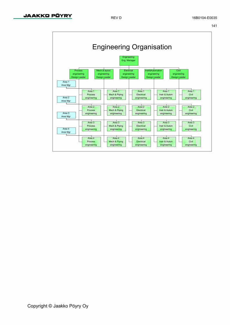
REV D 16B0104-E0035 141
Copyright © Jaakko Pöyry Oy
Engineering OrganisationEngineering
Eng. Manager
Area 1Area Mgr
Processengineering
Design Leader
Mech.& layoutengineering
Design Leader
Electricalengineering
Design Leader
Instr&Automationengineering
Design Leader
Civilengineering
Design Leader
Area 2Area Mgr
Area 3Area Mgr
Area 4Area Mgr
Area 1Process
engineering
Area 2Process
engineering
Area 3Process
engineering
Area 4Process
engineering
Area 1Mech & Piping
engineering
Area 2Mech & Piping
engineering
Area 3Mech & Piping
engineering
Area 4Mech & Piping
engineering
Area 1Electrical
engineering
Area 2Electrical
engineering
Area 3Electrical
engineering
Area 4Electrical
engineering
Area 1Instr & Automengineering
Area 2Instr & Automengineering
Area 3Instr & Automengineering
Area 4Instr & Automengineering
Area 1Civil
engineering
Area 2Civil
engineering
Area 3Civil
engineering
Area 4Civil
engineering

REV D 16B0104-E0035 142
Copyright © Jaakko Pöyry Oy
PICTURE 5/3 Site Organisation
Site Organisation
Area 1Area Mgr
Project/SiteManager
Civil ConstructionManager
MEI ConstructionManager
Area 2Area Mgr
Area 3Area Mgr
Area 4Area Mgr
Area 1Civil constr.supervision
Area 2
Civil constr.
supervision
Area 3
Civil constr.
supervision
Area 4Civil constr.
supervision
Area 1MEI construction
supervision
Area 2
MEI construction
supervision
Area 3
MEI construction
supervision
Area 4MEI construction
supervision
Site Office- Scheduling & Follow-up
- Doc. management
- IT services
- Cost control, QS
- Procurement
- Training
- QA
- Health, safety and security
- Secretariate
Mill operativemanagement
CommissioningManager
Area 1Commissioning
Area 2Commissioning
Area 3
Commissioning
Area 4
Commissioning

REV D 16B0104-E0035 143
Copyright © Jaakko Pöyry Oy
PICTURE 5/4 Typical Manning Curve on Site
BELL BAY PULP MILLManpower estimate during construction
0200400600800
10001200140016001800200022002400260028003000
1 3 5 7 9 11 13 15 17 19 21 23 25 27
Months
Man
pow
er
Total Mechanical PipingElectrical Instrumentation Civil
5.4.2 Project Planning and Scheduling The project time schedule was analysed to provide a basis for implementation. The time schedule aims to start the commercial production (commissioning phase) 24-26 months after the investment decision.
The pre-requisites for such a schedule are:
− Receipt of all necessary permits and approvals. − The preparatory engineering report has been approved and serves as a basis for
execution of the project. − The project organisation is in place. − Engineering companies have been hired. − Civil work contracts have been prepared, and the first contracts (site preparation,
earth moving) are ready to be awarded. − Main equipment contracts have been prepared for selecting all critical suppliers
before the investment decision.
The schedule is supported by the critical-path analysis and is optimal for efficient execution.

REV D 16B0104-E0035 144
Copyright © Jaakko Pöyry Oy
The critical path is determined by
− Permitting procedures. − Preparation of contracts before the project decision. − Project implementation, especially timely and well-coordinated civil work
supporting equipment erection in scheduled sequence. − Checkouts and start-up.
Main Milestones
− Investment decision D− Procurement of main machinery D + 1 week− Start of excavation D + 1 week− Start of erection D + 8-9 months− Start of checkouts D + 19 months− First cooking (start of production) D + 26 months
Scheduling The following time schedules are included in the pre-engineering report.
− Start-up schedule (dates are dependent on the final go-ahead decision)
The following schedules will be prepared in the ongoing project preparation phases and are dependent on the final implementation method for the project:
− Target time schedule − Detailed break-down of the first three (3) months’ activities on site − Co-ordinating civil construction and MEI erection schedule − Schedule and categories for completion of civil construction works at start of MEI
erection works − Updating of purchase time schedule − Goods and documents delivery schedules − Engineering time schedules (process, mechanical, piping, etc. disciplines).
The following scheduling work will be carried out by Construction Management:
− Review and coordination of the erection time schedules prepared by Suppliers and Contractors
− Schedule for temporary facilities and services including land-use plan − Schedule for special rooms (electrical and control rooms, laboratories, offices etc.) − Schedule for steel structures (coordination with MEI) − Schedule for equipment foundations − Civil construction work schedules according to the project’s needs − MEI installation schedules according to the project’s needs − Commissioning time schedules − Coordination schedule for overhead cranes.
Detailed work plans will be prepared by the respective contractors and coordinated by the Construction Management.

REV D 16B0104-E0035 145
Copyright © Jaakko Pöyry Oy
Progress Follow-up and Reporting The scope of project planning includes progress reporting in relation to the agreed time schedules. The reporting is based on feedback from corresponding executive units and disciplines.
Engineering Follow-up and Reporting
The engineering companies prepare monthly reports, reviewing the actual engineering status, covering all disciplines and works under their responsibility. The progress of each engineering discipline is reported in relation to the agreed time schedules. Special emphasis is placed on costs and scheduling.
Procurement Follow-up
Records will be kept of the procurement process. These include a monthly report of issued tender requisitions, tenders received, tender comparisons issued and orders or contracts signed.
Construction Follow-up
Detailed progress follow-up and reporting of civil construction and MEI erection works is necessary for timely coordination of site activities. This is done under the supervision of the construction management.
Checkout Follow-up
Checkout progress follow-up will be reported against a detailed checkout time schedule.
5.4.3 Contracting and Procurement
Enquiries and Tenders Enquiry specifications for main equipment, materials and auxiliaries as well as Civil and MEI installation works will be prepared according to the enclosed purchase time schedule. An “Approved Vendors” list will be produced and a “short list” will be approved for further tendering or negotiations. In this stage some delivery packages will be feasible to define but most of the enquiries and tenders should be analysed before any “bundling” into bigger entities of supply is done.
Equipment Delivery Contracts
The pre-engineering work has established the technology and major advantages, or drivers of the project to such an extent that the following decisions can be made:
− Select the most appropriate area-specific process equipment and specific-purpose equipment.
− Select the engineering standards for general-purpose standard equipment and construction materials (MEI).
− Select engineering methods and information management tools.

REV D 16B0104-E0035 146
Copyright © Jaakko Pöyry Oy
The purchase negotiations for each individual piece or logical unit of area-specific process equipment should be carried out separately in order to obtain the best possible technology for the new pulp mill, the guaranteed technical performance characteristics, availability and technical life time expectations of the equipment, quality and price.
Project has set a high prefabrication target to reduce the erection works at the site.
Industrial Awards
An Industrial Relations Officer should be appointed at an early stage. Together with the project management team a strategy for industrial labour relations on the Bell Bay site should be worked out together with the project management team. Based on the agreed strategy, necessary union or labour agreements should be negotiated for civil and MEI installation works on and off site.
MEI Erection Contracts It is important that the selected types of MEI Erection Contracts are in line with local practice and working methods. For example, preference should be given to a modular pipe and cable bridge design to allow a simpler and more productive installation process.
Buying general-purpose auxiliary and standard equipment, construction materials, civil and MEI erection work primarily through unit price contracts for the whole mill allows maximum flexibility in scheduling. Civil and MEI Erection Contracts are typically purchased in horizontal packages by discipline, but will also usually be split into geographically separate blocks, with each block including a few areas.
MEI Works are shared as follows:
Mechanical erection
− Main machinery − Piping − Insulation − Tanks and towers − Steel structures
Electrical erection
− Power supply − Process electrification − Building electrification
Instrumentation erection
− Manufacturing execution systems − Field instrumentation − Networks and wireless local area networks (WLAN)

REV D 16B0104-E0035 147
Copyright © Jaakko Pöyry Oy
These works will be shared in packages for different geographical and process area, like,
− Chip handling and fibre line − Drying machine − Evaporation plant and recovery boiler − Recausticising and lime kiln − Power boiler and power generation. − Balance of Plant (BOP) , including common systems and utilities for the whole mill.
MEI engineering, delivery and construction times can be heavily overlapped and civil and MEI erection contractors get paid for what they install.
MEI Erection Contracts will be prepared and negotiated based on the MEI Enquiry by the main engineering consultant. They may be of the type or combinations enumerated below:
− In Fixed Price type MEI Contracts the MEI Contractor agrees to furnish Services and Materials at a specified price, possibly with a mutually agreed upon escalation clause. This type of MEI Contract is most often employed when the scope of Services to be provided is well defined. − Lump Sum − Unit Price − Guaranteed Maximum Target Price − Bonus – Penalty
− In Cost Plus Contracts the MEI-Contractor agrees to furnish to the Purchaser Services and Material if included at actual cost, plus an agreed fee for his Services. This type of MEI Contract is employed most often when the scope of Services to be provided is not yet well defined., − Cost Plus Percentage Burden and Fee − Cost Plus Fixed Fee − Cost Plus Fixed Sum − Cost Plus Percentage Fee
Expediting and Quality Control The project management will prepare a plan for expediting and inspections to supervise the contractual manufacturing and delivery status of machinery, equipment and documents as well as the conformity of manufacturing against the agreed quality assurance plan.
The expediting and inspection work will be based partly on delivery status and quality inspection reports issued by the Suppliers and partly on expediting and inspection visits to the Suppliers’ works. The subsuppliers’ works are also visited when necessary. Instructions for suppliers’ progress reporting will be stated in the contracts.
REV D 16B0104-E0035 148
Copyright © Jaakko Pöyry Oy
Expediting and inspections include all activities necessary to ensure Suppliers’ compliance with the requirements of the project. Physical verification of the Suppliers’ progress by the expediter at certain intervals is normally the most important function for expediting. An expediting and inspection plan will be prepared, listing contracts/equipment and the number of visits.
5.5 Construction
5.5.1 General This section of implementation plan describes the main principals of mill construction activities. These activities include Civil Works, MEI Erection and Mill Site Services.
In the construction, the following predetermined drivers are to be taken into consideration;
− Cost-effectiveness − Co-ordination − Availability of resources − Single-team approach − Standardisation − Effective use of manpower − Modular system and prefabrication
5.5.2 Pre-construction Activities Pre-construction activities should commence when a positive investment decision is expected. In this connection, the following matters are to be investigated and identified:
− Legislation and required permits. − Contractor pre-qualification, labour conditions and availability, manpower estimates − Site preparation plan (land-use plan, storages, transport, communications, fire
prevention, safety and security, health, etc.). − Materials handling plan. − Transport routes (site and external). − Services to be provided to the contractors (water, electricity, air, effluent, etc.) − Site arrangement agreement. − Constructability analysis, including type of civil structures and impact on time
schedules (to be prepared by the Civil Engineer). − Prefabrication level in Civil Construction, MEI Erection and Main Equipment
Delivery. − Temporary facilities.

REV D 16B0104-E0035 149
Copyright © Jaakko Pöyry Oy
5.5.3 Site Management The physical implementation of the project on the site is carried out under the supervision of the construction management organisation, covering civil and building construction, MEI (mechanical, electrical, instrumentation) and installation work.
Checkout, water runs and start-up are not controlled by the construction management. Those activities will be executed by a separate organisation.
5.5.4 Quality Assurance Plan, Inspections A quality assurance plan (QAP) will be developed for construction and MEI erection works. The plan will include the rules for the administration of quality control procedures.
In many cases, local authorities have to be contacted to obtain standard methods relating to civil works.
The purpose of the QAP is to specify the technical requirements for the quality of the construction and the rules for administration of quality control to ensure, as far as possible, perfect quality of the finished plant. The QAP will therefore include instructions and procedures for the follow-up of quality during the construction and erection of the plant by means of intermediate inspections as well as tests to verify and certify the final quality.
Inspection, examination or testing activities will be performed throughout the erection period to verify that the erection work and components comply with approved drawings, standards, technical specifications or other specified requirements.
All contractors are obliged to develop their own project specific quality plans which are in line with project’s quality requirements. Contractors’ quality plans are subject to the project owner’s approval. Contractors will bear all cost incurred by them to fully implement all quality requirements.
5.5.5 Site Engineering
The main responsibility of the site engineering function is to provide all parties on site with the information required to perform their part of the project at all times. This is done by ensuring in advance that the documents arrive as scheduled, immediate distribution of incoming information, quick response to all queries and solving any design problems promptly on site.

REV D 16B0104-E0035 150
Copyright © Jaakko Pöyry Oy
The site engineering office also provides engineering support. When and if required, at least one experienced engineer from each discipline in the engineering team will move to the site. Their tasks on site are:
− To review the suppliers’ and contractors’ time schedules and to make sure that they are in line with master time schedules and/or project requirements.
− To prepare detailed construction/erection time schedules according to site needs − To review the construction/erection progress in order to ensure that the required
documents are available in time and to evaluate the impact of any schedule or technical change on the engineering schedule.
− To provide technical interpretation of drawings and other engineering documents − To make minor design changes as needed in close consultation with design leaders
in the engineering office. − To specify and, where appropriate, design site-engineered items such as temporary
construction facilities and utilities. − To check and verify documentation issues for contractors. − To prepare quantity take-offs for verifying progress payments to contractors when
required. − To assist the stores manager in verifying and inspecting the received goods. − To mark up and up-date drawings when required.
5.5.6 Safety and Security The target is zero accidents.
An organisation to handle safety and security matters will be established on the construction site.
The safety requirements, which influence the project, are to be identified in the following documents:
− Laws, statutes and stipulations, for example occupational health and safety act, labour protection act, etc.
− Project owner’s safety and security regulations.
Local practices must also be taken into account as well as the terms of the insurances. Suppliers of machinery, equipment, etc. have their own safety regulations, which must also be taken into account.
The safety and security organisation is responsible for ensuring that adequate security arrangements are made to safeguard the entire construction site during working and non-working hours.

REV D 16B0104-E0035 151
Copyright © Jaakko Pöyry Oy
5.5.7 Mill Site Services The very first activity at site is the establishment of geological reference network with three benchmarks.
All survey references will be made from these benchmarks.
There will be uniform surveying activity which works independently from contractors.
Mill site services are based on the manning level estimated earlier and include items such as offices, canteens, toilets, bathrooms, change rooms, locker rooms, social centres, on site transportation, security fences and gates, general traffic routes and main hauling routes, site clinic, lay down yards, prefabrication areas, stores, temporary utilities production and distribution, waste handling and sewage systems etc.
There is a need to establish communication with local authorities such as police, fire brigade, hospitals, telecommunications, municipality and labour unions etc.
Authorities with inspection function are good to keep on board from the beginning; these are civil construction, work safety, fire safety, environmental, pressure vessel and electrical safety etc.
Quality institutes and laboratories such as concrete and other civil laboratories, welding institutes etc. need to be contracted.
Off site services includes labour camps, transportation of labour, social services interconnected with such labour camps.
Mill site services need to be established in an early stage of the project to enable smooth construction of the mill itself from the first mobilisation to the last demobilisation.
5.5.8 Civil Works
Civil works would be contracted based on the specialty and ability of the contractors bearing in the mind the cost, time and quality.
The following works could be performed by mill wide contracts; earthmoving and site levelling, piling, steel structures, site surveying, etc.
The building related works could be split by area, by specialty and by work phase. i.e. Fibre line: Main underground foundations, building frame, platforms and floors, walls, base slab, machine foundations, apparatus rooms, finishing works, etc.
Due to the tight schedule civil construction needs to be well co-coordinated with equipment and MEI erection works and be integral part of the whole project.
Special attention is to be paid in the beginning to underground systems such as underground piping, sumps etc. As well foundations for the towers and tanks need to be addressed to be early enough in the schedule. Maximum utilisation of permanent overhead cranes is to be considered.

REV D 16B0104-E0035 152
Copyright © Jaakko Pöyry Oy
In those spaces where heating and air conditioning is provided the utilisation of these should be permitted during construction. The same applies to the lighting and power distribution as well as to water and sewer systems.
Civil construction will serve the purpose of equipment and MEI erection start and completion as early as possible.
The principles for grouting and penetrations will be agreed early enough in terms of the release for grouting and sizes of penetrations made by drilling in situ.
Room and floors finishing will be made based on the requirement of installation works.
The method of Quantity Surveying will be agreed at the contract stage and can be based on monthly evaluation or equal unit rate based concept.
5.5.9 MEI Erection The MEI Erection schedule needs to be integrated well in between the civil works and the need dates of mechanical completion. Typically, the installation sequence starts by an area-oriented approach but moves finally to a system-oriented approach, because in MEI erection the first target is to get utilities working early to enable removal of temporary facilities and commissioning of main equipment and processes.
Mechanical and piping erection usually starts with outdoor towers and tanks, buried utilities as well as pipe racks. Within the buildings, erection starts with the basement floor tanks, main process equipment and piping in main pipe streets. In mechanical and piping erection, modular units are used.
Earthing and grounding need to be addressed already during the civil construction phase. Electrical installation usually starts with high-voltage switchgear. Usually, the local or national electric power company is linked to these activities. Then follows installation of the power distribution system, including transformers and switchgears. Once the required rooms are ready, MCC’s are installed. Following cable tray installation (complete routes), cable pulling can commence. Particular attention is to be paid to avoid wrong erection/installation sequences, which may result in damage and rework. Cables can be coiled and terminated once the consumers such as motors have been installed.
Control and instrument installation can commence once sufficient mechanical erection completion is achieved. The equipment can be installed in cross connection rooms and other apparatus rooms once these spaces are technically complete and no other work needs to be performed inside. Field boxes and local instruments are installed, followed by cabling and tubing as applicable. Once again, the right timing needs to be evaluated to avoid damage and rework.
MEI Erection ends in mechanical completion when all installations have been done, all pressure tests and other cold tests completed and utilities (service systems) are up and running and commissioning of the main process can start. All quality documentation is in place at this stage.

REV D 16B0104-E0035 153
Copyright © Jaakko Pöyry Oy
5.5.10 Main Process Equipment Erection Main process equipment is delivered to the site by the Main Equipment Supplier. It is either the Supplier who will erect the equipment on site or there will be a separate contractor erecting it. In the latter case, the Supplier supplies only required specialist supervision to see that equipment is erected in accordance with instructions and quality requirements. The main process equipment should be delivered as prefabricated modules of maximum size to reduce the site work within the main equipment delivery battery limits (skid unit).
If a separate erection contractor is used, the main equipment supplier is required to inspect and approve the erection prior to grouting and connection of the skid unit to other installations. The main equipment supplier is responsible for mechanical completion, pre-commissioning and commissioning of his equipment (skid unit).
5.5.11 Approvals by Local Authorities Design and drawings to be issued to the local authorities for approval will be identified and handled by the Owner’s Engineer.
5.5.12 Quality Assurance Each contractor must present their quality assurance plan as a part of their purchase contract. The plans will be followed up and reported.
Reviews, Verification and Inspections
Design and other reviews are carried out in accordance with their respective project schedules. Verification of engineering will cover, besides the contractor’s own work and documentation, also the documentation of other project parties to the extent agreed in the engineering contract.
Internal inspection is required for all engineering documentation. Inspections means checking of completeness and correctness of documentation according to defined check lists of engineering disciplines.
Control of Changes and Nonconformities
Changes and nonconformities detected during the design and other reviews are documented and open items are followed up until the necessary corrective, change or complementary actions have been carried out.
5.5.13 Security/Safety and Environmental Issues Strict rules on these issues will be implemented during the construction phase, according to Gunns environmental policy, internal standards and other formal commitments for this particular project.
Waste Disposal Instructions for Suppliers and Contractors” will be submitted as a separate issue as a part of the Site Manual.

REV D 16B0104-E0035 154
Copyright © Jaakko Pöyry Oy
5.6 Cost Management
5.6.1 Project Budget When the project go-ahead decision has been made, the final capital cost estimate will be completed with the cost codes of accounts.
The project budget has been built up numerically and allocated to the project areas. The areas, forming the cost centres of the project, have further been split into activities (objects) such as machinery, civil works, electrical equipment etc.
The project budget is required as a basis for capital cost control.
5.6.2 Cost Engineering and Control The cost control activities include control of the budget, contracts/orders, invoices and project cash flow. The target of cost control is to keep costs within the established budget.
The cost control includes all the activities to plan, monitor and forecast the economic goals of the project. Throughout the project Cost Engineering will provide estimates to complete and will follow progress of both engineering and construction from a cost point of view.
5.7 Engineering
5.7.1 Project Standards
Mill Standards
The local and international standards and norms to be followed in the project have been defined during the pre-engineering phase and they will be further developed during the preparatory engineering phase.
5.7.2 Safety Marking European Suppliers are responsible for CE marking of their equipment, machinery and plants showing that these are certified to fulfil safety regulations as stated by Council of Europe. Corresponding Australian regulations has to be followed, as applicable. The required co-ordination will be carried out by the project management.
5.7.3 Approvals by Local Authorities Design and drawings to be issued to the local authorities for approval will be identified and handled by the Owner’s Engineer.

REV D 16B0104-E0035 155
Copyright © Jaakko Pöyry Oy
5.7.4 Quality Assurance Each contractor must present their quality assurance plan as a part of his purchase contract. The plans will be followed up and reported.
Reviews, Verification and Inspections Design and other reviews are carried out in accordance with their respective project schedules. Reviews here mean verification of engineering solutions applied to fulfil contract requirements. Verification of engineering will cover, besides the contractor’s own work and documentation, also the documentation of other project parties to the extent agreed in the engineering contract.
Internal inspection is required for all engineering documentation. Inspections means checking of completeness and correctness of documentation according to defined check lists of engineering disciplines.
Control of Changes and Nonconformities Changes and nonconformities detected during the design and other reviews are documented and open items are followed up until the necessary corrective, change or complementary actions have been carried out.
5.7.5 Detailed Engineering The modern way of detailed engineering is to create a virtual plant model with advanced modelling and design tools. Each discipline has its own applications for engineering. However, all disciplines are integrated to build up the same virtual model.
The virtual model is basically developed based on the selected concepts and solutions and purchased equipment.
During the detailed engineering phase, the improvements made in the virtual model can be viewed by browsers on-line or by producing separate user-friendly browsing models. The engineering documents are produced from models using pre-set views, definitions and parameters for selecting the required data and generating the documents.
5.8 Documentation and Information Management
There are several different commercial advanced document management systems (DMS) on the market for the management and transfer of project implementation documents.
The final selection of DMS will be made very soon after the final investment decision.

REV D 16B0104-E0035 156
Copyright © Jaakko Pöyry Oy
PICTURE 5/5 IT System
IT Systems
Document managementMultilateral at project phase
Documents for operations
Engineering tools & databasesPublishing for mill personnel
Other Mill IT –systems
Small Projectstools & resources
Project phase Production phaseStart-up
Mill IT infrastructure
Maintenance management- systems- collecting the information from suppliers
Training- concept- content- tools
5.8.1 General During the design and construction phase, the documents are subject to continuous changes and revisions. Instructions for document distribution, addressing and filing will be explicit and introduced to all parties in the project.
The organisation issuing a document is responsible for its correct coding and for maintaining an up-to-date record of the documents, their revisions, and distribution.
Each organisation which receives project documents from another organisation is responsible for keeping a record of the documents received.
Design work progress will be monitored in DMS by comparing actual issues against the plan. Monitoring will be based on project areas and types of documents.

REV D 16B0104-E0035 157
Copyright © Jaakko Pöyry Oy
5.8.2 Document Management A common document management service will be established and it will be used by all suppliers and local contractors in the project.
Key knowledge areas needed for successful document management in a distributed investment project are:
− IT system and support experience of hosting distributed document management systems.
− Knowledge of arranging the document management in pulp mill projects to ensure effective project work and good documentation for the operating mill.
The main targets set for document management are:
− Reduction of the work needed to archive documents at the construction site and other participating locations.
− Preventing extra costs caused by executing engineering or construction work with wrong versions of documents.
− Time and cost savings as documents are transported as little as possible in paper format.
− Minimising the work needed to collect the as-built documentation for the operating mills use.
− Fast access to the documentation at the construction site.
Document management service will be supplied from a professional hosting centre.
As the project will be geographically distributed, it is vital that documents are same time available at the construction site in Tasmania and for the project participants in Europe.
The document information collected and the structure of the system will be agreed together with Gunns so that it meets the requirements of the project and the operating mill. For effective entering of these documents, automated mass import/export tools have been designed. With these tools the project document management system can be linked to the document management system of different participating organisations.
When the project ends, Gunns will have different alternatives for delivery of as-built and project documentation:
− Collected on a DVD with the files and their document information so that they are easy to enter into the operating mills document management system.
− As a stand-alone DVD with a .html structure of the final revisions of the documents to be kept as the project archive.
− Transforming the DocHotel structure to suit the operating mill’s purposes and continuing with it as the operating mill’s document management system.

REV D 16B0104-E0035 158
Copyright © Jaakko Pöyry Oy
5.9 Preparation for Start-up Checkout is the last phase of the project before the start of production. During checkouts, the process will be simulated with dry functional tests and test runs and to some extent also with water as media, to ensure proper and safe function of all components before start-up.
PICTURE 5/6 Obligations of Parties during Commissioning (=Checkouts)
Obligations of Parties during CommissioningPhase
Tasks
Resp.
Assist.
Phase 1 (Erection) Phase 2 (Inspection)
ERECTION WORK & ERECTION INSPECTION
MEI Contractors, Suppliers, Supervisors
Commissioning and Mill Operations Teams
Phase 3a Phase 3b
COMMISSIONINGCommissioning Team, Contractors, Suppliers
MEI ContractorsMill Oper. Team
Certificate ofEnd of Erection
Certificate ofCompletion
Certificate ofTake-over
Mill Oper.Team
Phase 4
TEST RUN
Mill Operations Team
Commissioning Team
DCS in use,power on
Electrical installation (MEI Contractor))
Instrument installation (MEI Contractor)
Inspection
Inspection
Inspection
Inspection
Piping installationMEI Contractor
Mechanical installationMEI Contractor/Supplier
FunctionalTest
WaterRun
Test Run(with media)
Start-up ofPulp Dryer
(Stock on wire)
Hand-over forWater Run
Electr.=I/O-Tests, RotationInstr. = Loop Check-out
Check-out

REV D 16B0104-E0035 159
Copyright © Jaakko Pöyry Oy
5.9.1 Check-out The check-out and water run activities are mainly a quality assurance function. The aim of check-out is to eliminate problems owing to mechanical, electrical and instrument defects as well as installation errors and inconsistencies, which could hamper a successful start-up. Carefully executed check-out and water runs are a guarantee for satisfactory and continuous production.
The check-out of individual sub-systems can start after the completion, inspection and acceptance of the respective MEI installations.
During check-out of the plant, it will be verified that the erection work has been completed and inspected, and that all specified inspection, examination or testing activities have been performed and approved.
5.9.2 Test Runs During test runs, the function of the process and the process control system will be tested with start/stop sequences, interlocks and simulating disturbances.
The purpose of a water run is to test systems with water simulating the process, in order to detect and simulate any remaining defects and faults. The tuning and calibration of instruments are also carried out as far as possible without process media, including adjustment of valves, stuffing boxes and cooling water. In some cases, temporary piping must be installed for circulating water within a test system.
During test runs all equipment will be observed with regard to noise, vibrations, temperature, leakage and anything out the ordinary. Any deviations will be reported.
5.9.3 Take-over
After successful start-up and an accepted production test, Gunns will take over the equipment. Gunns then issues a "Certificate of Taking-over (Provisional Acceptance)", which will be the indisputable document signifying the beginning of the guarantee period of the equipment.
From the Taking-over (Provisional Acceptance) date, the Gunns personnel is responsible for the running of the plant.

REV D 16B0104-E0035 160
Copyright © Jaakko Pöyry Oy
5.10 Preparations for Operations Preparations for operations have commenced during the pre-engineering phase and will be continued while waiting for the investment decision and thereafter.
5.10.1 Manning and Organisation
Mill Manning Plan The shift working schema will consist of 3 shifts completed by 4 teams.
The harbour activities increase the demand for labour.
The proposed preliminary mill organisation includes a total of 291 employees divided as follows:
Salaried Staff Management 12 Economy and Administration 9 Material Handling 6 Personnel Administration 6 Marketing and Sales 5 Production 23 Maintenance /Planning 16 Subtotal 77
Hourly Paid Production 100 Maintenance 66 Warehouse and Harbour 48 Subtotal 214
The aim is to utilise third-party services whenever it is economically justified.
The above personnel is estimated to be needed for the mill operations after the start-up period. In the beginning, a start-up crew of expatriates will be required.
Maintenance, Mill Services
The design of contracted mill services will be discussed with potential service suppliers. Final selection of the organisation model and possible maintenance service partners will be done after selection of main machinery suppliers.

REV D 16B0104-E0035 161
Copyright © Jaakko Pöyry Oy
5.10.2 Material and Service Contract Management To ensure the supply of materials and services for the commissioning and initial operation phase, there must be scheduled delivery contracts for:
− Raw materials and chemicals − Production consumables − Maintenance materials − Maintenance and housekeeping services
5.10.3 Maintenance Policy Suppliers will be requested to estimate maintenance requirements for expected availability and to submit a life-cycle maintenance plan based on experiences of similar mills selected as references. In addition, they will be requested:
− To submit a life-cycle spare parts plan based on experiences of similar mills selected as references.
− To assess the availability of a production line, an individual equipment or equipment assembly.
− To submit a plan for follow-up lifetime load of the equipment providing initial data for planning preventive maintenance and repairs.
− To submit price specifications separately for two (2) years’ Technical Guarantee Period and after that annually for the next eight (8) years.
In the implementation phase, these data will be used in developing a detailed maintenance scope with the selected machine suppliers.
5.10.4 Quality Management The mill operations will be defined and supported in accordance with a formal TQM concept.
Documentation and workflows will be designed and implemented to cover demands of ISO 9000/2000.