report no 9 - hot spot/notch stress analysis - using femap
DESCRIPTION
in this report, the effect of root geometry on the weld toe is studied. Hot-Spot and Effective Notch stress concepts are used to model the geometry in the FEMAP software.The geometric model is generated using Autodesk Inventor.TRANSCRIPT

Report No. 9(The Last Report: Including all the results being to be published in thesis)
(29 January 2013)

1 IntroductionIt previous reports hot-spot and Effective Notch Stress (ENS) approaches have been utilized to obtain the results for the plate with straight stiffener under tension. Effects of different geometric modeling of root have been studied as well. In this report the different shapes for stiffener would be studied as well as bending load case. Fatigue life estimation will also be studied for different cases as well.
The outline of this report will include:
Hot-spot approach for different stiffener geometries under axial tension and bending ENS method for u-shape root and keyhole under axial tension and bending
1.1.1 Important notes about this report
Since the main aim of this thesis is studying fatigue of a typical welded structure I pursued all the calculations based on the last few report ( Error: Reference source not found .)
Figure 1. Overall Geometry

2 Method
2.1 Hot-spot approach
Hot-spot approach is applied for coarse and semi-fine meshing according to recommendations of [1]. According to the geometry hot-spot is of type ‘a’.
2.1.1 Straight Stiffener
Two approaches have been used, semi fine meshing and coarse meshing, the first is based on linear 8-node hexahedral elements whereas the latter is based on coarser 20-node parabolic hexahedral element. Both approaches use extrapolation method stipulated in [1] and [2]. The same procedure has been applied on both axial tension and bending moment load cases.
Based on nominal stress, the detail for would be of FAT class 71 as shown in Figure 2 from [1].
Figure 2 for 150 < L < 300, nominal stress is of FAT 71 class
Since in the full model L = 200 mm > 150 mm, the FAT class based on hot-spot stress would be FAT 90 as shown in Figure 3 [1].
Figure 3 FAT 90 based on hot-spot approach
2.1.1.1 Semi-Fine Meshing
Eq. (1) which is stipulated in [1] is used for semi-fine meshing. The positions for reading stress are shown in Figure 4 [1] which is derived from [1].

Figure 4 Locations for extrapolate stress to the notch for semi-fine meshing
σ hs=1.67σ0.4 t−0.67σ1.0 t (1)
2.1.1.2 Coarse Meshing
The procedure is shown in Figure 5 and Eq. (2) derived from [1].
Figure 5 Locations for extrapolate stress to the notch for coarse meshing
σ hs=1.5σ0.5 t−0.5σ 1.5 t (2)
2.1.2 Angled Stiffener
A 45o angle has been considered for this case. It is shown in Figure 6 [1].

Figure 6 Angled stiffener
2.1.3 Curved Stiffener
As depicted in the following figure as the case no 522 from [1].
Figure 7 Curved Stiffener
2.1.4 Bending Case
Because of asymmetry of bending moment around horizontal plane (XY), the ¼ symmetric model has been used as shown in Figure 8. Two alternatives have been utilised to model the bending moment on the baseplate end which are discussed later.

Figure 8 Bending model
2.2 Effective Notch Stress (ENS)
Another method which has been used in this study for calculating stress in toe and fatigue life is effective notch stress (ENS). Since the aim of this study is fatigue life based on toe stress and on the other hand the root side cannot be excluded from modelling in ENS approach, so 4 different models for root has been used which are explained as follow.
a) A 0.5-mm gap without rounding with 4-mm throatb) A 2-mm gap with 1-mm rounding and same throat (4-mm)c) A 2-mm gap with 1-mm rounding and same ligament as case (a)d) A 0.5-mm gap with 1-mm rounding and same ligament as (a)

Figure 9 Different models for root side
All four models have been studied and compared in previous reports, in this final report, u-shaped rounding (case ‘c’) and keyhole (Case ‘d’) have been studied in more detail, meshing size has been decreased even more to 0.1 mm. in new models increase in mesh size is more smooth when going far from notch in different directions.

2.2.1.1 Case (c)
Figure 10 Case (c)
2.2.1.2 Case (d)

Figure 11 Case (d)
Figure 12 Other view for case (d)

3 Results
3.1.1.1 Hot-Spot coarse mesh
Hot-spot is modeled without considering any gap, hexahedral elements have been used and “Extrude” and “Revolve” commands have been used to mesh the model.
Figure 13 Peak Stress for hot-spot method for linear extrapolation
For hot spot two extrapolation formulae have been used, equation (1) and (2) of [1] which are repeated in equations 2.1.3) and 2.1.4).

Figure 14 Another view for hot-spot method
Table 1 Hot Spot Values for Linear Extrapolation
Position of Node in respect to toe Max Principal Stress Value0.4 t = 3.2 mm 1.67 MPa1.0 t = 8.0 mm 1.23 MPa
σ hs=1.67σ0.4 t−0.67σ1.0 t=¿
1.67×1.55−0.67×1.23=1.76 MPa2.1.3)
For quadratic extrapolation I use a relatively finer model as follow:

Figure 15 Hot-spot model for quadratic extrapolation
Figure 16 another view for quadratic extrapolation

Position of Node in respect to toe Max Principal Stress Value0.4 t = 3.2 mm 1.45 MPa0.9 t = 8.0 mm 1.24 MPa1.4 t = 11.2 mm 1.18 MPa
σ hs=2.52σ0.4 t−2.24 σ0.9 t+0.72σ1.4 t=¿
2.52×1.45−2.24×1.24+0.72×1.18=1.73MPa2.1.4)
3.1.1.2 Effective Notch Stress
As it was mentioned in Introduction, 4 different geometries have been modeled and analyzed which are discussed as follows:
3.1.1.2.1 Case ‘a’, 0.5-mm gapThe model is as follow:
Figure 17 Case 'a'
A general overview of the meshing for this model is depicted in the following figure:

Figure 18 Meshing for case 'a'
The FEMAP results with “Corner Data” and without “Corner Data” are presented in Figure 19 and Figure20.

Figure 19 With “Corner Data”
Figure 20 Without "Corner Data"

3.1.1.2.2 Case ‘b’, 2-mm gap with constant throat
Figure 21 Case ‘b’, 2-mm gap with constant throat
Figure 22 Another View for case 'b'

As it could be expected, the stress in weld root is higher in this case, because there is less material to withstand the tension.
3.1.1.2.3 Case ‘c’, 2-mm gap with constant ligament
Figure 23 Case 'c', 2-mm gap with constant ligament

Figure 24 Another view for case 'c'
Here the stress in the root is lower than case ‘b’.
3.1.1.2.4 Case ‘d’, 0.5-mm gap with 2-mm roundingBecause of the stress concentration on the boundary of the 2-mm circle and the internal wall of the gap, the modeling of this geometry was more challenging. The final result is as follow:
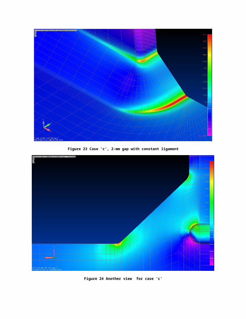
Figure 25 Case 'd', 0.5-mm gap with 2-mm circular rounding
Figure 26 Another view for case 'd'

3.2 Results
The results are summarized in
Table 2 Summary of results
Stress Value Stress Type Stress in toe (MPa) Stress in root (MPa)Nodal Elemental without “Corner
Data and “No Averaging”Nodal Elemental without
“Corner DataHot-spot, Linear extrapolation
Hot-spot 1.76 M NA NA NA
Hot-spot, Quadratic extrapolation
Hot-spot 1.73 NA NA NA
Case ‘a’ Peak Stress 3.75 2.81 NA NACase ‘b’ Peak Stress 4.48 3.71 4.29 3.34Case ‘c’ Peak Stress 4.43 3.68 3.98 3.51Case ‘d’ Peak Stress 4.36 4.16 3.43 3.11
3.3 Concerns, and questions
1. The root stress in all cases is less than toe stress but not that much. 2. Three of ENS models have been assessed by using hexahedral element where only one model has
been analyzed using tetrahedral elements, it seems there is no meaningful drastic difference in the results, but a conclusion needs more models and more meshing variations.
3. By increasing the number of elements, the meshing operation gets very complicated and analysis time increases drastically, therefore elements which are used in hexa model are of 0.2-mm size which can be improved and normalized after the model is finalized.
3.4 Bibliography
[1] A. Hobbacher, Recommendations for Fatigue Design of Welded Joints and Components, International Institute of Welding, XIII-2151-07/XV-1127r18-03, 2008.
[2] E. Niemi, W. Fricke and S. J. Maddox, Fatigue Abalysis of Welded Components, Designer's guide to the structural hot-spot stress apprach (IIW-1430-00), Woodhead Publishing Limited, 2006.
[3] W. Fricke, Guideline for the Fatigue Assessment by Notch Stress Analysis for Welded Structures, International Institute of Welding, 2010.
[4] E. Niemi, Stress Determination for Fatigue Analysis of Welded Components, IIS/IIW-1221-93, Abington Publishing,, 1995.
