report of can
TRANSCRIPT

8/3/2019 Report of Can
http://slidepdf.com/reader/full/report-of-can 1/19
CONROLLER AREA NETWORK
MTech (DECS),SJCIT 1 2011-12
CHAPTER 1
INTRODUCTION
The Controller Area Network (CAN) is a serial communications protocol that efficiently
supports distributed real-time control with a very high level of data integrity. Though conceived and
defined by BOSCH in Germany for automotive applications, CAN is not restricted to that
industry. CAN fullfils the communication needs of a wide range of applications, from high-speed
networks to low-cost multiplex wiring. For example, in automotive electronics, engine control units,
sensors and anti-skid systems may be connected using CAN, with bit-rates up to 1 Mbit/s. At the
same time, it is cost effective to build CAN into vehicle body electronics, such as lamp clustersand electric windows, to replace the wiring harness otherwise required.
The intention of the CAN specification is to achieve compatibility between any two
CAN implementations. Compatibility, however, has different aspects with respect to, for
example, electrical features and the interpretation of data to be transferred. To achieve design
transparency and implementation flexibility CAN has been subdivided into three layers:
a. The Object Layer
b. The Transfer Layer
c. The Physical Layer
The Object Layer and the Transfer Layer comprise all services and functions of the data link
layer defined by the ISO/OSI model. The scope of the Object Layer includes: determining which
messages are to be transmitted; deciding which messages received by the Transfer Layer are
actually to be used; and, providing an interface to the Application Layer related hardware. There is
considerable freedom in defining object handling. The Transfer Layer is principally concerned with
the transfer protocol, i.e. controlling the framing, performing arbitration, error checking, error
signaling and fault confinement. Within the Transfer Layer it is decided whether the bus is free for
starting a new transmission, or whether reception of a message is just starting.

8/3/2019 Report of Can
http://slidepdf.com/reader/full/report-of-can 2/19
CONROLLER AREA NETWORK
MTech (DECS),SJCIT 2 2011-12
CHAPTER 2
CAN OVERVIEW
Most network applications follow a layered approach to system implementation. This
systematic approach enables interoperability between products from different manufacturers. A
standard was created by the International Standards Organization (ISO) as a tem- plate to follow
for this layered approach. It is called the ISO Open Systems Interconnection (OSI) Network
Layering Reference Model. The CAN protocol itself implements most of the lower two layers of
this reference model. The communication medium portion of the model was purposely left out of
the Bosch CAN specification to enable system designers to adapt and optimize the communication
protocol on multiple media for maximum flexibility (twisted pair, single wire, optically isolated,RF, IR, etc.). With this flexibility, however, comes the possibility of interoperability concerns.
To ease some of these concerns, the International Standards Organization and Society of
Automotive Engineers (SAE) have defined some protocols based on CAN that include the
Media Dependant Interface definition such that all of the lower two layers are specified. ISO11898
is a standard for high-speed applications, ISO11519 is a standard for low-speed applications, and
J1939 (from SAE) is targeted for truck and bus applications. All three of these protocols specify a
5V differential electrical bus as the physical interface. The rest of the layers of the ISO/OSI protocol
stack are left to be implemented by the system software developer. Higher Layer Protocols (HLPs)
are generally used to implement the upper five layers of the OSI Reference Model.
HLPs are used to:
1) standardize startup procedures including bit rates used,
2) distribute addresses among participating nodes or types of messages,
3) determine the structure of the messages, and
4) provide system-level error handling routines. This is by no means a full list of the functions HLPs
perform, however it does describe some of their basic functionality.
The below figure shows how the control functions before using the Controller area network and also shows the control
functions by using Controller area network.

8/3/2019 Report of Can
http://slidepdf.com/reader/full/report-of-can 3/19
CONROLLER AREA NETWORK
MTech (DECS),SJCIT 3 2011-12
Figure 2.1: Before CAN
Many vehicles already have a large number of electronic control systems. The growth of
automotive electronics is the result partly of the customerµs wish for better safety and greater comfort and partly of the governmentµs requirements for improved emission control and reduced
fuel consumption. Control devices that meet these requirements have been in use for some time in
the area of engine timing, gearbox and carburetor throttle control and in anti-block systems (ABS)
and acceleration skid control (ASC). The complexity of the functions implemented in these
systems necessitates an exchange of data between them. With conventional systems, data is
exchanged by means of dedicated signal lines, but this is becoming increasingly difficult and
expensive as control functions become ever more complex. In the case of complex control systems
(such as Motronic) in particular, the number of connections cannot be increased much further.
Moreover, a number of systems are being developed which implement functions covering more
than one control device. For instance, ASC requires the interplay of engine timing and carburettor
control in order to reduce torque when drive wheel slippage occurs. Another example of functions
spanning more than one control unit is electronic gearbox control, where ease of gear changing can

8/3/2019 Report of Can
http://slidepdf.com/reader/full/report-of-can 4/19
CONROLLER AREA NETWORK
MTech (DECS),SJCIT 4 2011-12
be improved by a brief adjustment to ignition timing.
If we also consider future developments aimed at overall vehicle optimization, it becomes
necessary to overcome the limitations of conventional control device linkage. This can only be
done by networking the system components using a serial data bus system. It was for this reason
that Bosch developed the ´Controller Area Network´ (CAN), which has since been standardized
internationally (ISO 11898) and has been ´cast in silicon´ by several semiconductor
manufacturers.
Figure 2.2 With CAN
2.1 PROTOCOL BASICS
Carrier Sense Multiple Access with Collision Detection (CSMA/CD)
The CAN communication protocol is a CSMA/CD proto- col. The CSMA stands for
Carrier Sense Multiple Access. What this means is that every node on the net- work must
monitor the bus for a period of no activity before trying to send a message on the bus
(Carrier Sense). Also, once this period of no activity occurs, every node on the bus has an equal

8/3/2019 Report of Can
http://slidepdf.com/reader/full/report-of-can 5/19
CONROLLER AREA NETWORK
MTech (DECS),SJCIT 5 2011-12
opportunity to transmit a message (Multiple Access). The CD stands for Collision Detection. If
two nodes on the network start transmitting at the same time, the nodes will detect the µcollision
and take the appropriate action. In CAN protocol, a non- destructive bitwise arbitration method is
utilized. This means that messages remain intact after arbitration is completed even if collisions
are detected. All of this arbitration takes place without corruption or delay of the higher priority
message.
There are a couple of things that are required to support non-destructive bitwise
arbitration. First, logic states need to be defined as dominant or recessive. Second, the
transmitting node must monitor the state of the bus to see if the logic state it is trying to send
actually appears on the bus. CAN defines a logic bit 0 as a dominant bit and a logic bit 1 as a
recessive bit. A dominant bit state will always win arbitration over a recessive bit state,
therefore the lower the value in the Message Identifier (the field used in the message arbitra- tion
process), the higher the priority of the message. As an example, suppose two nodes are trying to
transmit a message at the same time. Each node will monitor the bus to make sure the bit that it is
trying to send actually appears on the bus. The lower priority message will at some point try to send
a recessive bit and the monitored state on the bus will be a dominant. At that point this node loses
arbitration and immediately stops transmitting. The higher priority message will continue until
completion and the node that lost arbitration will wait for the next period of no activity on the bus and
try to transmit its message again.

8/3/2019 Report of Can
http://slidepdf.com/reader/full/report-of-can 6/19
CONROLLER AREA NETWORK
MTech (DECS),SJCIT 6 2011-12
CHAPTER 3
CAN NETWORK FUNCTIONS
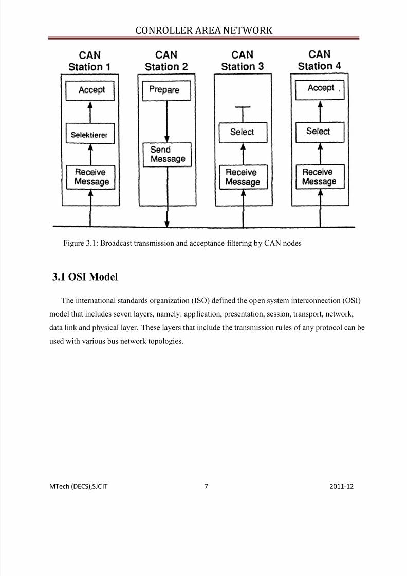
When data are transmitted by CAN, no stations are addressed, but instead, the content of the
message (e.g. rpm or engine temperature) is designated by an identifier that is unique throughout
the network. The identifier defines not only the content but also the priority of the message. This is
important for bus allocation when several stations are competing for bus access. If the CPU of a
given station wishes to send a message to one or more stations, it passes the data to be transmitted
and their identifiers to the assigned CAN chip (´Make ready´). This is all the CPU has to do to
initiate data exchange. The message is constructed and transmitted by the CAN chip. As soon as
the CAN chip receives the bus allocation (´Send Message´) all other stations on the CAN network
become receivers of this message (´Receive Message´). Each station in the CAN network, having
received the message correctly, performs an acceptance test to determine whether the data received
are relevant for that station (´Select´). If the data are of significance for the station concerned they
are processed (´Accept´), otherwise they are ignored. A high degree of system and configuration
flexibility is achieved as a result of the content-oriented addressing scheme.
It is very easy to add stations to the existing CAN network without making any hardware or
software modifications to the existing stations, provided that the new stations are purely receivers.
Because the data transmission protocol does not require physical destination addresses for the
individual components, it supports the concept of modular electronics and also permits multiple
reception (broadcast, multicast) and the synchronization of distributed processes: measurements
needed as information by several controllers can be transmitted via the network, in such a way that
it is unnecessary for each controller to have its own sensor.
CAN transmits signals on the CAN bus which consists of two wires, a CAN-High and CAN-
Low. These two wires are operate in differential mode, that is they are carrying invertedvoltages.
8/3/2019 Report of Can
http://slidepdf.com/reader/full/report-of-can 7/19
CONROLLER AREA NETWORK
MTech (DECS),SJCIT 7 2011-12
Figure 3.1: Broadcast transmission and acceptance filtering by CAN nodes
3.1 OSI Model
The international standards organization (ISO) defined the open system interconnection (OSI)model that includes seven layers, namely: application, presentation, session, transport, network,
data link and physical layer. These layers that include the transmission rules of any protocol can be
used with various bus network topologies.

8/3/2019 Report of Can
http://slidepdf.com/reader/full/report-of-can 8/19
CONROLLER AREA NETWORK
MTech (DECS),SJCIT 8 2011-12
CHAPTER 4
MESSAGE FRAME FORMATS
The CAN protocol supports two message frame formats, the only essential difference being in
the length of the identifier (ID). In the standard format the length of the ID is 11 bits and in the
extended format the length is 29 bits.
Figure 4.1: Standard Frame Format
The message frame for transmitting messages on the bus comprises seven main fields. A
message in the standard format begins with the start bit ´start of frame´, this is followed by the
´arbitration field´, which contains the identifier and the ´RTR´ (remote transmission request) bit,
which indicates whether it is a data frame or a request frame without any data bytes (remote
frame). The ´control field´ contains the IDE (identifier extension) bit, which indicates either
standard format or extended format, a bit reserved for future extensions and - in the last 4 bits - a
count of the data bytes in the data field. The ´data field´ ranges from 0 to 8 bytes in length and is
followed by the ´CRC field´, which is used as a frame security check for detecting bit errors.
The ´ACK field´, comprises the ACK slot (1 bit) and the ACK delimiter (1 recessive bit).
The bit in the ACK slot is sent as a recessive bit and is overwritten as a dominant bit by those
receivers which have at this time received the data correctly (positive acknowledgement). Correct
messages are acknowledged by the receivers regardless of the result of the acceptance test. The
end of the message is indicated by ´end of frame´. ´Intermission´ is the minimum number of bit
periods separating consecutive messages. If there is no following bus access by any station, the
bus remains idle (´bus idle´).

8/3/2019 Report of Can
http://slidepdf.com/reader/full/report-of-can 9/19
CONROLLER AREA NETWORK
MTech (DECS),SJCIT 9 2011-12
Figure 4.2: Extended Frame format
4.1 MESSAGE FRAME TYPE
Message transfer is manifested and controlled by four different frame types:
1) DATA FRAME
A Data frame carries data from a transmitter to the receivers.
2) REMOTE FRAME
A Remote frame is transmitted by a bus node to request the transmission of the Data
frame with the same Identifier.
3) ERROR FRAME
An Error frame is transmitted by any node on detecting a bus error.
4) OVERLOAD FRAME
An Overload frame is used to provide for an extra delay between the preceding and
the succeeding Data or Remote frames.
4.1.1 CAN Message Frame Description
CAN protocol defines four different types of messages (or Frames). The first and most
common type of frame is a Data Frame. This is used when a node transmits information to any
or all other nodes in the system. Second is a Remote Frame, which is basically a Data
Frame with the RTR bit set to signify it is a Remote Transmit Request . The other two frame
types are for handling errors. One is called an Error Frame and one is called an Overload
Frame. Error Frames are generated by nodes that detect any one of the many protocol errors
defined by CAN. Overload errors are generated by nodes that require more time to process

8/3/2019 Report of Can
http://slidepdf.com/reader/full/report-of-can 10/19
CONROLLER AREA NETWORK
MTech (DECS),SJCIT 10 2011-12
messages already received. Data Frames consist of fields that provide additional information about the message as
defined by the CAN specification. Embedded in the Data Frames are Arbitration Fields, Control
Fields, Data Fields, CRC Fields, a 2-bit Acknowledge Field and an End of Frame. TheArbitration Field is used to prioritize messages on the bus. Since the CAN protocol defines a
logical 0 as the dominant state, the lower the number in the arbitration field, the higher priority
the message has on the bus. The arbitration field consists of 12-bits (11 identifier bits and one
RTR bit) or 32-bits (29 identifier bits, 1-bit to define the message as an extended data frame, an SRR
bit which is unused, and an RTR bit), depending on whether Standard Frames or Extended Frames
are being utilized. The current version of the CAN specification, version 2.0B, defines 29-bit
identifiers and calls them Extended Frames. Previous versions of the CAN specification defined 11-
bit identifiers which are called Standard Frames.
Figure 4.3: Data Frame
As described in the preceding section, the Remote Transmit Request (RTR) is used by

8/3/2019 Report of Can
http://slidepdf.com/reader/full/report-of-can 11/19
CONROLLER AREA NETWORK
MTech (DECS),SJCIT 11 2011-12
a node when it requires information to be sent to it from another node. To accomplish an RTR, a
Remote Frame is sent with the identifier of the required Data Frame. The RTR bit in the
Arbitration Field is utilized to differentiate between a Remote Frame and a Data Frame. If
the RTR bit is recessive, then the message is a Remote Frame. If the RTR bit is dominant, the
message is a Data Frame.
The Control Field consists of six bits. The MSB is the IDE bit (signifies Extended
Frame) which should be dominant for Standard Data Frames. This bit determines if the
message is a Standard or Extended Frame. In Extended Frames, this bit is RB1 and it is reserved.
The next bit is RB0 and it is also reserved. The four LSBs are the Data Length Code (DLC)
bits. The Data Length Code bits determine how many data bytes are included in the message.
It should be noted that a Remote Frame has no data field, regardless of the value of the DLC
bits.
The Data Field consists of the number of data bytes described in the Data Length Code
of the Control Field.
The CRC Field consists of a 15-bit CRC field and a CRC delimiter, and is used by
receiving nodes to determine if transmission errors have occurred.
The Acknowledge Field is utilized to indicate if the message was received correctly. Any
node that has correctly received the message, regardless of whether the node processes or discards
the data, puts a dominant bit on the bus in the ACK Slot bit time.
Figure 4.4: Error frame

8/3/2019 Report of Can
http://slidepdf.com/reader/full/report-of-can 12/19
CONROLLER AREA NETWORK
MTech (DECS),SJCIT 12 2011-12
The last two message types are Error Frames and Overload Frames. When a node detects one of
the many types of errors defined by the CAN protocol, an Error Frame occurs. Overload Frames
tell the network that the node sending the Overload Frame is not ready to receive additionalmessages at this time, or that intermission has been violated.
4.2 Errors Detected
CRC Error
A 15-bit Cyclic Redundancy Check (CRC) value is calculated by the transmitting node and
this 15-bit value is transmitted in the CRC field. All nodes on the network receive this message,
calculate a CRC and verify that the CRC values match. If the values do not match, a CRC error
occurs and an Error Frame is generated. Since at least one node did not properly receive the
message, it is then resent after a proper intermission time.
Acknowledge Error
Acknowledge Slot (which it has sent as a recessive bit) contains a dominant bit. In the
Acknowledge Field of a message, the transmitting node checks if the This dominant bit would
acknowledge that at least one node correctly received the message. If this bit is recessive, then
no node received the message properly. An Acknowledge Error has occurred. An Error Frame
is then generated and the original message will be repeated after a proper intermission time.
Form Error
If any node detects a dominant bit in one of the fol- lowing four segments of the
message: End of Frame, Interframe Space, Acknowledge Delimiter or CRC Delimiter, the
CAN protocol defines this to be a form violation and a Form Error is generated. The original
message is then resent after a proper intermission time.
Bit Error
A Bit Error occurs if a transmitter sends a dominant bit and detects a recessive bit, or if
it sends a recessive bit and detects a dominant bit when monitoring the actual bus level and
comparing it to the bit that it has just sent. In the case where the transmitter sends a recessive

8/3/2019 Report of Can
http://slidepdf.com/reader/full/report-of-can 13/19
CONROLLER AREA NETWORK
MTech (DECS),SJCIT 13 2011-12
bit and a dominant bit is detected during the Arbitration Field or Acknowledge Slot, no Bit
Error is generated because normal arbitration or acknowledgment is occurring. If a Bit
Error is detected, an Error Frame is generated and the original message is resent after a
proper intermission time.
Stuff Error
CAN protocol uses a Non-Return±to-Zero (NRZ) transmission method. This means that
the bit level is placed on the bus for the entire bit time. CAN is also asynchronous, and bit
stuffing is used to allow receiving nodes to synchronize by recovering clock information
from the data stream. Receiving nodes synchronize on recessive to dominant transitions. If there
are more than five bits of the same polarity in a row, CAN will automatically stuff an opposite
polarity bit in the data stream. The receiving node(s) will use it for synchronization, but will
ignore the stuff bit for data purposes. If, between the Start of Frame and the CRC Delimiter,
six consecutive bits with the same polarity are detected, then the bit stuffing rule has been
violated. A Stuff Error then occurs, an Error Frame is sent, and the message is repeated.

8/3/2019 Report of Can
http://slidepdf.com/reader/full/report-of-can 14/19
CONROLLER AREA NETWORK
MTech (DECS),SJCIT 14 2011-12
CHAPTER 5
TIME TRIGGERED CAN
Time Triggered controller area network developed by BOSCH in 2000 and this CAN is
based on CAN data link layer as specified in International Standard Organization 11898. It may
use standardized physical layers such as high speed transceiver or fault tolerant transceiver. Time
triggered controller area provides mechanisms to schedule CAN messages time triggered as well as
event triggered. This is work like a CAN but it has some special features like time triggered as well
as event triggered. And it is based on time triggered communication clocked by a reference
message of a time master.
Figure 5.1: Time Triggered controller area network

8/3/2019 Report of Can
http://slidepdf.com/reader/full/report-of-can 15/19
CONROLLER AREA NETWORK
MTech (DECS),SJCIT 15 2011-12
In Time Triggered CAN the period between the two consecutive reference message is the
basic cycle and this basic cycle contains several time windows in between the reference messages
and these time windows are different in sizes and these time windows offers necessary space to
transmit messages. The time windows are namely Exclusive time window, Arbitrating time
window, and free time window. And these time windows are vary in size.
In Exclusive time window we can transmit and receive only periodic messages and in
Arbitrating time window we can only transmit and receive spontaneous messages that is it
transmits at a time but in the Exclusive time window we can transmit at a period of time that¶s why
the name time triggered CAN.
Figure 5.2: Exchange of information in TTCAN

8/3/2019 Report of Can
http://slidepdf.com/reader/full/report-of-can 16/19
CONROLLER AREA NETWORK
MTech (DECS),SJCIT 16 2011-12
CHAPTER 6
APPLICATIONS
CAN applied in various fields such as
Passenger cars
Trucks and buses
Off-highway and off-road vehicles
Passenger and cargo trains
Maritime electronics
Aircraft and aerospace electronics
Factory automation
Industrial machine control
Lifts and escalators
Building automation
Medical equipment and devices
Non-industrial control
Non-industrial equipment
6.1 ATTRIBUTES OF CAN
1) Multi master capabilities.
2) Broadcast messaging.
3) Sophisticated error detecting mechanism.
4) Retransmission of faulty messages.
5) Availability of more than 50 controllers from more than 15 manufacturers.

8/3/2019 Report of Can
http://slidepdf.com/reader/full/report-of-can 17/19
CONROLLER AREA NETWORK
MTech (DECS),SJCIT 17 2011-12
6.2 ADVANTAGES
1) Easy to add stations to existing CAN n/w without making any hardware or software
modifications.
2) Permits multiple reception and synchronization of distributed processes.
3) Data can be transmitted via n/w in such a way that it is unnecessary for each station to have to
know who the producer of data is.
4) Easy servicing and upgrading of networks.

8/3/2019 Report of Can
http://slidepdf.com/reader/full/report-of-can 18/19
CONROLLER AREA NETWORK
MTech (DECS),SJCIT 18 2011-12
CHAPTER 7
CONCLUSION
The CAN protocol was optimized for systems that need to transmit and receive
relatively small amounts of information (as compared to Ethernet or USB, which are designed to
move much larger blocks of data) reliably to any or all other nodes on the network. CSMA/CD
allows every node to have an equal chance to gain access to the bus, and allows for smooth
handling of collisions. Since the protocol is message-based, not address based, all messages on the
bus receive every message and acknowledge every message, regardless of whether in needs the
data or not. This allows the bus to operate in node-to-node or multicast messaging formats without
having to send different types of messages. Fast, robust message transmission with fault
confinement is also a big plus for CAN because faulty nodes will automatically drop off the bus
not allowing any one node from bringing a network down. This effectively guarantees that
bandwidth will always be available for critical messages to be transmitted. With all of these
benefits built into the CAN protocol and its momentum in the automotive world, other markets
will begin to see and implement CAN into their systems.

8/3/2019 Report of Can
http://slidepdf.com/reader/full/report-of-can 19/19
CONROLLER AREA NETWORK
MTech (DECS),SJCIT 19 2011-12
BIBILOGRAPHY
[1] CAN in Automation GmbH, ³CAN-connected sensors´, site http://www.can-cia.org/.
[2] Holger Zeltwanger, Thilo Schuman, ³CANopen±based Transducer NetWork´, site
http://www.ieeta.pt/lse/rtn2004/preprints/7-prep.pdf.
[3] Yoshihiro Miyazaki, Hiroaki Fukumaru, ³Open Control Systems and DeviceNet Applications´,
Hitachi Review, Volume 48, No.1-6, June 1999
[4] ANSI/ISA-50.02, Part 2-1992, ³Fieldbus Standard for Use in Industrial Control Systems Part 2:
Physical Layer Specification and Service Definition´, 1992.
[5] Gustavo Silva, M. Dias Pereira, ³Fieldbus: An Integrated Solution for Measurement and
Control´, Proc. VI International Conference on Measurement and Control in Complex
Systems,MCCS-2001, Vinnytsia, Ucrânia, pp. 80-81, Oct.2001.
[6] Pat Richards, ³Understanding Microchip¶s CAN Module BitTiming´, Application Note
AN754, Microchip Technology Inc,2001.