report of the kai-eric jensen, jensen oven company, … supervising. a special approved cock...
TRANSCRIPT
325
Report of the
Technical Committee on Ovens and Furnaces
Algirdas Underys, ChairA. Finkl & Sons Inc., IL [U]
Rep. Forging Industry Association
J. William Sheppard, SecretaryGeneral Motors Corporation, MI [U]
Rep. NFPA Industrial Fire Protection Section
Gary S. Andress, LMG Property Engineering, WI [I]John J. Barron, Vacuum Furnace Systems Corp., PA [M]David Collier, Eclipse Combustion, Inc., IL [M]Bruce R. Deeds, Maxon Corporation, IN [M]Leo P. Donovan, FM Global, MA [I] Rep. FM Global/FM ResearchJohn D. Eley, GN Electronics Inc., IL [SE]John C. Herron, Electric Furnace Company, OH [M]James A. Huber, JSH Associates, Ltd., OH [SE]Jeffrey M. Hunt, ALCOA, VA [U]Ted Jablkowski, P. E., North American Manufacturing Co., CT [M] Rep. Industrial Heating Equipment AssociationJerry D. Jablonski, Delphi Automotive Systems, MI [U]J. D. Jackson, Crycorp, LLC, CT [IM]Fred K. Jensen, Jensen Industries, Inc., MI [M]Gary D. Keil, Caterpillar Incorporated, IL [U]William M. Keough, AFC-Holcroft, MI [M]Richard J. Martin, Exponent Incorporated, CA [SE]Peter B. Matthews, Hartford Steam Boiler Inspection & Insurance Co., CT [I]Paul Mattiola, Air Products & Chemicals, Inc., PA [IM]Glen R. Mortensen, Kemper Insurance Companies, IL [I]Raymond Ostrowski, Consultant-Industrial Safety, AZ [SE]John R. Puskar, Combustion Safety, Inc., OH [SE]Mircea Stefan Stanescu, BOC Gases, NC [IM]Mark V. Stender, Surface Combustion, Inc., OH [M]Grant F. Tiefenbruck, 3M Company, MN [U]Jay D. Tindall, Royal & SunAlliance, PA [I] Rep. Amerian Insurance Services GroupLynn K. Underwood, CNA Risk Management Property, IL [I]Jacques van Heijningen, Siemens Building Technologies, Inc., IL [M]W. H. White, White Consulting Services, OH [SE]Peter J. Willse, GE Global Asset Proection Services, CT [I]
Alternates
Randall Conklen, Caterpillar Incorporated, IL [U] (Alt. to G. D. Keil)Richard A. Gallagher, Industrial Risk Insurers, PA [I] (Alt. to P. J. Willse)James J. Garmaker, 3M Company, MN [U] (Alt. to G. F. Tiefenbruck)Brent D. Hill, LMG Property, TX [I] (Alt. to G. S. Andress)
Kai-Eric Jensen, Jensen Oven Company, Inc., MI [M] (Alt. to F. K. Jensen)Michael C. Polagye, FM Global, MA [I] (Alt. to L. P. Donovan)Jeff Rafter, Maxon Corporation, IN [M] (Alt. to B. R. Deeds)David S. Rohrbaugh, Drever Company, PA [M] (Alt. to T. Jablkowski)Raymond E. Serafini, Jr., BOC Gases, PA [U] (Alt. to M. S. Stanescu)
Staff Liasion: Theodore C. Lemoff
This list represents the membership at the time the Committee was balloted on the text of this report. Since that time, changes in the membership may have occurred. A key to classifications is found at the front of the document.
Committee Scope: This Committee shall have primary responsibility for documents on control of fire and explosion hazards in drying ovens for japan, enamel, and other finishes, bakery ovens, core ovens, annealing and heat treating furnaces, and other special atmosphere furnaces, including equipment for other special atmospheres.
The Technical Committee on Ovens and Furnaces is presenting three Reports for adoption, as follows:
Report I: The Technical Committee proposes for adoption, a complete revision to NFPA 86, Standard for Ovens and Furnaces, 1999 edition. NFPA 86-1999 is published in Volume 4 of the 2001 National Fire Codes and in separate pamphlet form.
NFPA 86 has been submitted to letter ballot of the Technical Committee on Ovens and Furnaces, which consists of 31 voting members. The results of the balloting, after circulation of any negative votes, can be found in the report.
Report II: The Technical Committee proposes for adoption, the withdrawal of NFPA 86C, Standard for Industrial Furnaces Using a Special Processing Atmosphere, 1999 edition. NFPA 86C-1999 is published in Volume 4 of the 2001 National Fire Codes and in separate pamphlet form.
NFPA 86C has been submitted to letter ballot of the Technical Committee on Ovens and Furnaces, which consists of 31 voting members. The results of the balloting, after circulation of any negative votes, can be found in the report.
Report III: The Technical Committee proposes for adoption, a withdrawal of NFPA 86D-1999, Standard for Industrial Furnaces Using Vacuum as an Atmosphere, 1999 edition. NFPA 86D is published in Volume 4 of the 2001 National Fire Codes and in separate pamphlet form.
NFPA 86D has been submitted to letter ballot of the Technical Committee on Ovens and Furnaces, which consists of 31 voting members. The results of the balloting, after circulation of any negative votes, can be found in the report.
326
NFPA 86 — May 2003 ROP — Copyright, NFPA
NFPA 86
(Log #CP1)86-1-(Entire Document) : Accept SUBMITTER: Technical Committee on Ovens and Furnaces, RECOMMENDATION: The Technical Committee on Ovens and Furnaces proposes a complete revision of NFPA 86, Standard for Ovens and Furnaces, 1999 edition. The revision will incorporate NFPA 86C, Standard for Industrial Furnaces Using a Special Processing Atmosphere, 1999 edition and NFPA 86D, Standard for Industrial Furnaces Using Vacuum as an Atmosphere, 1999 edition. This proposal contains the combined requirements from NFPA 86, NFPA 86C and NFPA 86D, along with all changes made by committee proposals and public proposals accepted by the committee as shown at the end of this report. In the combination, revisions were made to comply with the NFPA Style Manual. SUBSTANTIATION: This combination will provide one document for all Oven and Furnace requirements.COMMITTEE MEETING ACTION:AcceptNUMBER OF COMMITTEE MEMBERS ELIGIBLE TO VOTE:31VOTE ON COMMITTEE ACTION: AFFIRMATIVE: 29 NOT RETURNED: 2 Mattiola and vanHeijningen
————————————————-
(Log #68)86-2-(Chapter 2 Definitions) : Accept SUBMITTER: Ted Jablkowski, P.E., North American Mfg. Co., Ltd.RECOMMENDATION: Delete the following text: Cock, Supervising. A special approved cock incorporating in its design a means for positive interlocking with a main fuel safety shutoff valve so that, before the main fuel safety shutoff valve can be opened, all individual burner supervising cocks must be in the fully closed position. SUBSTANTIATION: The use of supervising gas cocks in lieu of electronic flame supervision is no longer recognized in NFPA 86. COMMITTEE MEETING ACTION:AcceptNUMBER OF COMMITTEE MEMBERS ELIGIBLE TO VOTE:31VOTE ON COMMITTEE ACTION: AFFIRMATIVE: 29 NOT RETURNED: 2 Mattiola and vanHeijningen
————————————————-
(Log #69)86-3-(Chapter 2 Definitions) : Accept in Principle SUBMITTER: Ted Jablkowski, P.E., North American Mfg. Co., Ltd.RECOMMENDATION: Revise text as follows: Interlock, Proved Low-Fire Start. A burner start interlock in which a control sequence ensures that a high-low or modulated burner is in the low fire at a reduced firing rate position is suitable for reliable ignition before the burner can be ignited. SUBSTANTIATION: In some cases, the most reliable ignition rate may not be at the low fire rate and may be at the 10 or 20 percent rate. COMMITTEE MEETING ACTION:Accept in PrincipleCOMMITTEE STATEMENT: See committee draft, Committee Proposal 86-1 (Log # CP1),Definition of Interlock, Proved Low-Fire Start.NUMBER OF COMMITTEE MEMBERS ELIGIBLE TO VOTE:31VOTE ON COMMITTEE ACTION: AFFIRMATIVE: 29 NOT RETURNED: 2 Mattiola and vanHeijningen
————————————————-
(Log #34)86-4-(2.1 Closed Position Indicator Switch) : Accept in Principle SUBMITTER: Jim Houston, Industrial Heating Equipment Assn.RECOMMENDATION: Add text to read as follows: Closed Position Indicator Switch - A closed position indicator switch shall indicate in the closed position of the valve. The switch shall indicate the closure when the closure member is within 1 mm of its closed position. SUBSTANTIATION: This definition is an excerpt from prEN 161 Automatic Shutoff Valves for Gas Burners and Gas Appliances, paragraph 7.11. The secondary optional definition from prEN 161 for flow rate limitation is not recommended by this committee for use in this definition. The definition of Closed Position Indicator switch is intended to clarify the use of an auxiliary switch set to actuator near the closed position of the SSOV and is used in our proposal for 5-7.2.2.COMMITTEE MEETING ACTION:Accept in PrincipleCOMMITTEE STATEMENT: Refer to Committee Proposal 86-1 (Log #CP1), definition of switch, closed poistion indicator.NUMBER OF COMMITTEE MEMBERS ELIGIBLE TO VOTE:31VOTE ON COMMITTEE ACTION: AFFIRMATIVE: 29 NOT RETURNED: 2 Mattiola and vanHeijningen
COMMENT ON AFFIRMATIVE: COLLIER: We agree that a measurement is needed, but not necessarily that “is within 1 mm” is acceptable. My be too strict or too lenient depending on valve design.
————————————————-
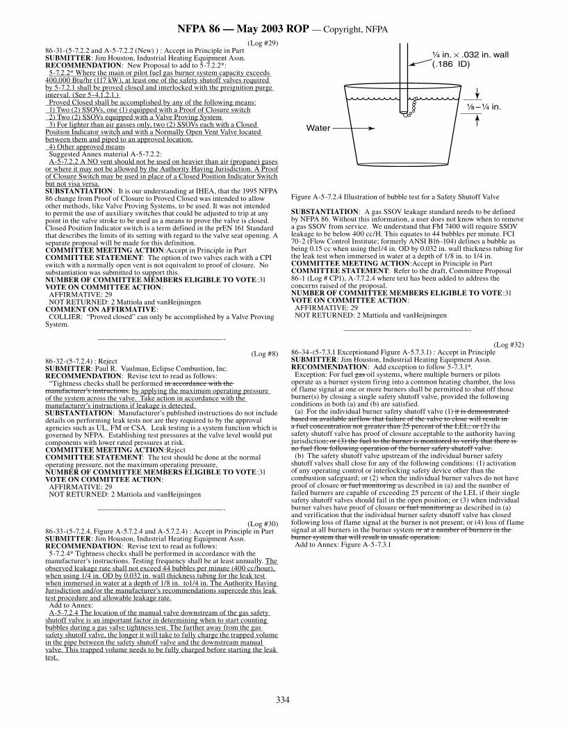
(Log #35)86-5-(2.1 Proof of Closure) : Accept in Principle SUBMITTER: Jim Houston, Industrial Heating Equipment Assn.RECOMMENDATION: Add text to read as follows: Proof of Closure*. A proof of closure switch shall have the switch setting factory set and sealed. Field adjustment of the proof of closure switch is not permitted. The switch shall include at least one set of contacts which close only after the valve port is closed and which open prior to the opening of the valve port. Additional movement to actuate the switch after the valve port is closed shall be either: a) provided directly by the port closing element, or b) provided by additional valve operator movement which relies on the port closing element being in the closed position. (Add to Annex) *According to ANSI Z21.21/CSA 6.5 standard, the valve port is considered closed when leakage through the valve does not exceed 1 ft3 per hour (0.028 m3/hr) gas at 150 percent of rated inlet pressure applied to the valve inlet. Note: The preceding is a manufacturing test only. It should not be applied to field leakage tests, which are conducted at normal system pressure. According to ASME/CSD-1 1998 edition, Valve, Proof of Closure: A safety shutoff valve equipped with an interlock which will be actuated only after the valve is fully closed.SUBSTANTIATION: 1) The above is a verbatim definition from 1995 and 1998 editions of ANSI Z21.21/CSA 6.5 standard and 1998 Addenda a and b which is equivalent to the 2000 edition. 2) SSOV “Proved Closed” and “Proof of Closure” are not defined in NFPA 86, but are a requirement in the standard under 5-4.1.2.1, 5-7.2.2 and 5-7.3.2 and perhaps others.COMMITTEE MEETING ACTION:Accept in PrincipleCOMMITTEE STATEMENT: Refer to the committee draft, Committee Proposal 86-1 (Log #CP1), definition of Switch, proof of closure.NUMBER OF COMMITTEE MEMBERS ELIGIBLE TO VOTE:31VOTE ON COMMITTEE ACTION: AFFIRMATIVE: 29 NOT RETURNED: 2 Mattiola and vanHeijningen
————————————————-
(Log #36)86-6-(2.1 Valve Proving System) : Accept in Principle SUBMITTER: Jim Houston, Industrial Heating Equipment Assn.RECOMMENDATION: Add text to read as follows: Valve Proving System*. A system to check the effective closure of automatic shut-off valves by detecting leakage. It may consist of a programming unit, a measuring device, valves and other functional assemblies. Add to Annex: *In accordance with the ANSI Z21.21/CGA 6.5 standard, the system should detect leakage exceeding an equivalent of 1 ft3 per hour (0.028 m3/hr) at 150 percent of rated inlet pressure applied to the valve inlet during the manufacturer’s production testing or per the requirements of the authority having jurisdiction. Note: The preceding pressure reference at 150 percent of rated inlet pressure is a manufacturing test only. It should not be applied to field leakage tests which are conducted at normal system pressure. SUBSTANTIATION: 1) The first two sentences in the proposed definition are verbatim from EN1643, paragraph 3.1 of the International Standard for Valve Proving systems and EN1643 requires leakage to be less than 1.7 ft3/hour. 2) Note: It must be recognized that it is not practical to test at 150% of the inlet pressure in the field but that this requirement is consistent with the ANSI Z21.21/CGA 6.5 Standard for Proof of Closure switches. 3) The present use of the term “proved closed” in 5-7.2.2 is viewed to permit the use of alternatives to “proof of closure” mechanisms. 4) The listing agencies are not consistent with their requirements for proof of closure requiring valve seal overtravel. FM requires valve seal overtravel for all electrical safety circuit interlocks. Others do not require valve seal overtravel. There needs to be consistency among definitions in order for the intent of NFPA 86 standards in this regard to be followed. The ANSI Z21.21/CGA 6.5 standard definition was proposed for this reason. 5) UL429 or 822 dropped their requirement for valve seal overtravel. It is still in UL795 for burners. FM still requires it. 6) At present there are no standards defining the acceptable amount of leakage through the valve seal for valves in the field. The present leakage standards are for valve seal leakage as they are shipped from the manufacturer. 7) FM is changing to <400 cc per hour. By comparison, the requirement is <235cc /hour UL & CGA 6.5. These standards are intended for the valve seal quality as it leaves the factory but is not meant to be a field standard. At present, there is no standard for leakage of SSOV in the field except for FM 6-9 which refers to 1 cu3/hour leakage standard. Will this change too?
327
NFPA 86 — May 2003 ROP — Copyright, NFPA
8) Purpose is for purge / safety interlock. UL 795 uses valve seal overtravel. FM uses proof of closure. 9) “Proved Closed” versus “Proof of Closure?” “Proof of Closure” is only used in the exception following 5-7.1.2. It may be re-worded to say Proved Closed.COMMITTEE MEETING ACTION:Accept in PrincipleCOMMITTEE STATEMENT: Refer to committee draft, Committee Proposal 86-1 (Log #CP1), definition of Valve proving system and appendix text.NUMBER OF COMMITTEE MEMBERS ELIGIBLE TO VOTE:31VOTE ON COMMITTEE ACTION: AFFIRMATIVE: 29 NOT RETURNED: 2 Mattiola and vanHeijningen
————————————————-
(Log #85)86-7-(2.1 Definitions and A-2-1) : Accept in Principle SUBMITTER: Richard J. Martin, Exponent Inc.RECOMMENDATION: Revise text as follows: Afterburner: See Thermal Oxidizer. Catalytic Oxidizer. See Thermal Oxidizer. Incinerator, fume: Any separate or independent combustion equipment or device that entrains the process exhaust for the purpose of direct thermal or catalytic destruction, which can include heat recovery. See Thermal Oxidizer. Thermal Oxidizer. An independently controlled, enclosed combustion system whose purpose is to destroy volatile organic compound (VOC) and/or hydrocarbon (HC) gases or vapors using elevated temperature, residence time, mixing, excess oxygen, and in some cases, catalysts. A.2.1 Thermal Oxidizer. Types of Thermal Oxidizers include: • Afterburner - A direct thermal oxidizer, installed in series, downstream of process equipment that generates VOC or HC. It is sometimes called a “secondary combustion chamber”. • Direct Thermal Oxidizer (TO) - A combustion device where the burner(s) directly heat the VOCs or HCs to the destruction temperature without heat recovery to the incoming gases. • Direct Catalytic Oxidizer - A combustion device where the burner(s) directly heat the VOCs or HCs to the destruction temperature, prior to their introduction to a destruction catalyst, without heat recovery to the incoming gases. The catalytic destruction temperature is lower than the non-catalytic (direct thermal) destruction temperature. • Recuperative Thermal Oxidizer - A combustion device where the burner(s) directly heat the VOCs or HCs to the destruction temperature and the hot products of combustion are used to indirectly heat the incoming gas stream, before it contacts the burner flame. • Recuperative Catalytic Oxidizer - A combustion device where the burner(s) directly heat the VOCs or HCs to the catalytic destruction temperature prior to their introduction to a destruction catalyst, and after which, the products of combustion are used to indirectly heat the incoming gas stream, before it contacts the burner flame. The catalytic destruction temperature is lower than the non-catalytic (direct thermal) destruction temperature. • Regenerative Thermal Oxidizer (RTO) - A combustion device where the burner(s) may directly heat the VOCs or HCs after the gas stream is preheated to the destruction temperature by the periodic flow reversal of the gas stream through heat storage media that alternately have been heated by the product gases, during an exhaust cycle and then have given up their heat to the incoming reactant gases, during an inlet cycle. Note: RTOs are frequently operated in a “self-sustaining” mode where the heat release from the reactant gases is sufficient to maintain the destruction temperatures, and firing of the burner is not required after the initial preheating of the heat storage media is completed. • Regenerative Catalytic Oxidizer (RCO) - A combustion device where the burner(s) may directly heat the VOCs or HCs after the gas stream is preheated to the destruction temperature by the periodic flow reversal of the gas stream through catalytically-coated heat storage media that alternately have been heated by the product gases, during an exhaust cycle and then have given up their heat to the incoming reactant gases, during an inlet cycle. Note: RCOs are frequently operated in a “self-sustaining” mode where the heat release from the reactant gases is sufficient to maintain the catalytic destruction temperatures, and firing of the burner is not required after the initial preheating of the heat storage media is completed. • Flameless Thermal Oxidizer (FTO) - A combustion device where the burner preheats the heat storage media prior to the introduction of the VOCs or HCs, and subsequently the destruction is carried out in the interstices of the heat storage media in a flameless, self-sustaining manner, without flow reversal. FTOs can be direct recuperative, or regenerative. SUBSTANTIATION: Since the advent of the Clean Air Act Amendments in 1990, which require companies to install systems that reduce the emission of organic vapors and other gases, many new technologies have been developed to control these compounds. Whereas vapor control previously had been utilized only for safety or economic considerations, as regulations have tightened, the “environmental” driver now has supplanted these for many manufacturing businesses. As the new technologies have been introduced, and as older technologies have been applied in new ways to meet specific combinations of environmental and process needs, new failure modes have evolved, some of which contribute to increased risks of
explosion, fire, and chemical release. The intent of this proposed change is formally to acknowledge some of these new types of systems in the 86 Standard, so that its applicability to their installation and operation will be more definitive, and less subject to interpretation. Another intent is to de-emphasize the terms “fume incinerator” and “afterburner”, which are not favored by current suppliers. COMMITTEE MEETING ACTION:Accept in PrincipleCOMMITTEE STATEMENT: Refer to the committee draft, Committe Proposal 86-1 (Log # CP1), where the proposed definitions have been added.NUMBER OF COMMITTEE MEMBERS ELIGIBLE TO VOTE:31VOTE ON COMMITTEE ACTION: AFFIRMATIVE: 29 NOT RETURNED: 2 Mattiola and vanHeijningen
————————————————-
(Log #22)86-8-(2-1.1) : Reject SUBMITTER: Jim Houston, Industrial Heating Equipment Assn.RECOMMENDATION: Revise text as follows: See 2-1.1 Provision for Auxiliary Fuel. Gas-burning installations shall be in accordance with the applicable provisions of NFPA 54, National Fuel Gas Code, and NFPA 58, Liquefied Petroleum Gas Code. Oil-burning installations shall comply with NFPA 31, Standard for the Installation of Oil-Burning Equipment. Fuel burners and related controls for of all incinerators shall be equipped with safety controls that will automatically shut off the fuel supply to the burner in the event the burner fails to ignite or its flame becomes extinguished or in the event of insufficient draft shall comply with the applicable provisions of NFPA 86.SUBSTANTIATION: Reference to NFPA 86 is omitted in the present NFPA 82 text under safety control for fuel burners. Ignition and preheat burners systems used on incinerators should follow NFPA 86. The deleted text above is redundant to the requirements of NFPA 86.COMMITTEE MEETING ACTION:RejectCOMMITTEE STATEMENT: The proposal appears revise NFPA 82. It is recommended that the proposal be submitted to NFPA 82.NUMBER OF COMMITTEE MEMBERS ELIGIBLE TO VOTE:31VOTE ON COMMITTEE ACTION: AFFIRMATIVE: 29 NOT RETURNED: 2 Mattiola and vanHeijningen
————————————————-(Log #86)
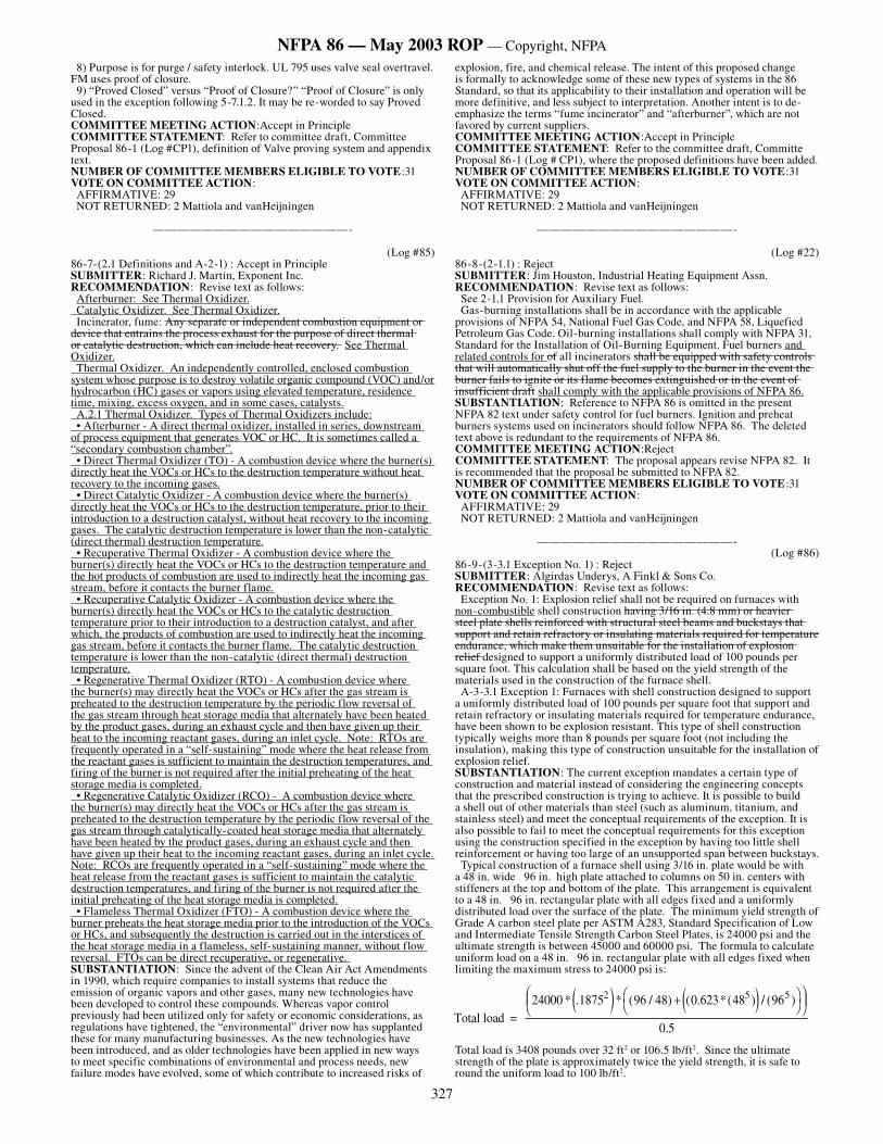
86-9-(3-3.1 Exception No. 1) : Reject SUBMITTER: Algirdas Underys, A Finkl & Sons Co.RECOMMENDATION: Revise text as follows: Exception No. 1: Explosion relief shall not be required on furnaces with non-combustible shell construction having 3/16 in. (4.8 mm) or heavier steel plate shells reinforced with structural steel beams and buckstays that support and retain refractory or insulating materials required for temperature endurance, which make them unsuitable for the installation of explosion relief designed to support a uniformly distributed load of 100 pounds per square foot. This calculation shall be based on the yield strength of the materials used in the construction of the furnace shell. A-3-3.1 Exception 1: Furnaces with shell construction designed to support a uniformly distributed load of 100 pounds per square foot that support and retain refractory or insulating materials required for temperature endurance, have been shown to be explosion resistant. This type of shell construction typically weighs more than 8 pounds per square foot (not including the insulation), making this type of construction unsuitable for the installation of explosion relief. SUBSTANTIATION: The current exception mandates a certain type of construction and material instead of considering the engineering concepts that the prescribed construction is trying to achieve. It is possible to build a shell out of other materials than steel (such as aluminum, titanium, and stainless steel) and meet the conceptual requirements of the exception. It is also possible to fail to meet the conceptual requirements for this exception using the construction specified in the exception by having too little shell reinforcement or having too large of an unsupported span between buckstays. Typical construction of a furnace shell using 3/16 in. plate would be with a 48 in. wide 96 in. high plate attached to columns on 50 in. centers with stiffeners at the top and bottom of the plate. This arrangement is equivalent to a 48 in. 96 in. rectangular plate with all edges fixed and a uniformly distributed load over the surface of the plate. The minimum yield strength of Grade A carbon steel plate per ASTM A283, Standard Specification of Low and Intermediate Tensile Strength Carbon Steel Plates, is 24000 psi and the ultimate strength is between 45000 and 60000 psi. The formula to calculate uniform load on a 48 in. 96 in. rectangular plate with all edges fixed when limiting the maximum stress to 24000 psi is:
Total load is 3408 pounds over 32 ft2 or 106.5 lb/ft2. Since the ultimate strength of the plate is approximately twice the yield strength, it is safe to round the uniform load to 100 lb/ft2.
Total load = 24000 * .18752� � � � ��
���
���
���* ( / ) ( . * ( ) / ( )
.
96 48 0 623 48 96
0 5
5 5
328
NFPA 86 — May 2003 ROP — Copyright, NFPA
COMMITTEE MEETING ACTION:RejectCOMMITTEE STATEMENT: The practice of not allowing explosion relief was based on the use of heavy refractories. Accepting the proposal would extend the elimination of explosion relief to those that do not use refractory linings.NUMBER OF COMMITTEE MEMBERS ELIGIBLE TO VOTE:31VOTE ON COMMITTEE ACTION: AFFIRMATIVE: 29 NOT RETURNED: 2 Mattiola and vanHeijningen
————————————————-
(Log #1)86-10-(3-3.1 Exception No. 3 (New) ) : Accept in Principle NOTE: This Proposal appeared as Comment 86-6 (Log #18) which was held from the May 1999 ROC on Proposal 86-2.SUBMITTER: Leonard J. Shorek, General Motors Corp.RECOMMENDATION: Add the following exception to Paragraph 3-3.1: Exception No. 3: Explosion-relief panels shall not be required on indirect fired ovens if it can be demonstrated by calculation or by LEL detectors that the combustible concentration in the heating chamber and the combustion chamber cannot exceed 25 percent of the LEL. SUBSTANTIATION: Ovens with explosion relief cannot be completely sealed. As a result, condensable fumes leak from ovens with explosion relief contaminating the surrounding atmosphere and condensing inside of the oven insulation. This leakage results in fire hazards and health hazards. Many indirect fired ovens have been constructed with totally welded interior skins without untoward results, when it has been demonstrated by calculation or by LEL detectors that the concentration of combustibles cannot exceed 25 percent of the LEL.COMMITTEE MEETING ACTION:Accept in Principle Refer to committee draft, Proposal 86-1 (Log #CP1), Section 5.3.1 (e) where the concept is added.COMMITTEE STATEMENT: The option of LEL monitors is not accepted because calculation should demonstrate that LEL conditions can not be achieved.NUMBER OF COMMITTEE MEMBERS ELIGIBLE TO VOTE:31VOTE ON COMMITTEE ACTION: AFFIRMATIVE: 29 NOT RETURNED: 2 Mattiola and vanHeijningen
————————————————-
(Log #11)86-11-(3-3.2) : Reject SUBMITTER: Francois Tanguay, Pyradia, IncRECOMMENDATION: Add new text as follows: The relief area can be constituted of the access doors only. SUBSTANTIATION: Many ovens are built with only one access door acting as the explosion relief also.COMMITTEE MEETING ACTION:RejectCOMMITTEE STATEMENT: NFPA 86 does not preclude the use of doors as explosion relief vents.NUMBER OF COMMITTEE MEMBERS ELIGIBLE TO VOTE:31VOTE ON COMMITTEE ACTION: AFFIRMATIVE: 29 NOT RETURNED: 2 Mattiola and vanHeijningen
————————————————-
(Log #10)86-12-(3-3.3) : Reject SUBMITTER: Francois Tanguay, Pyradia, IncRECOMMENDATION: Add new text as follows: Explosion-relief vents don’t have to be vented to the outside. SUBSTANTIATION: NFPA 68 requires explosion vent to be vented to the outside, but it is almost always impractical to do the same on an oven.COMMITTEE MEETING ACTION:RejectCOMMITTEE STATEMENT: NFPA 86 does not prohibit terminating explosion vents inside a buliding. NFPA 68 is a guide, and has no mandatory requirements. NUMBER OF COMMITTEE MEMBERS ELIGIBLE TO VOTE:31VOTE ON COMMITTEE ACTION: AFFIRMATIVE: 29 NOT RETURNED: 2 Mattiola and vanHeijningen
————————————————-
(Log #2)86-13-(3-3.7) : Reject NOTE: This Proposal appeared as Comment 86-9 (Log #20) which was held from the May 1999 ROC on Proposal 86-2.SUBMITTER: Thomas E. Myers, Despatch IndustriesRECOMMENDATION: Revise text to read as follows: “Explosion-relief vents for a long furnace shall be reasonably distributed throughout the entire furnace length. However, the maximum distance between explosion-relief vents shall not exceed five times the oven’s smallest inside dimension (width or height).” SUBSTANTIATION: No supporting calculations or basis is given for the “five times” rule. “Reasonably distributed” covers the engineering and safety requirement adequately.COMMITTEE MEETING ACTION:RejectCOMMITTEE STATEMENT: The requirement is based empirical models determined by test.NUMBER OF COMMITTEE MEMBERS ELIGIBLE TO VOTE:31VOTE ON COMMITTEE ACTION: AFFIRMATIVE: 29 NOT RETURNED: 2 Mattiola and vanHeijningen
————————————————-
(Log #23)86-14-(4-2.4.1.1 and 4.3.4.1.1) : Reject SUBMITTER: Jim Houston, Industrial Heating Equipment Assn.RECOMMENDATION: Revise text to read as follows: 4-2.4.1.1 Individual manual shutoff valves for equipment isolation shall be provided for shutoff of the fuel to each piece of equipment. This valve shall be capable of being locked in the closed position and located for ready direct unimpeded access without the use of a ladder or other portable device and without the need for removing or moving any panel, door, or similar covering for access. 4-3.4.1.1 Individual manual shutoff valves for equipment isolation shall be provided for shutoff of the fuel to each piece of equipment. This valve shall be capable of being locked in the closed position and located for ready direct unimpeded access without the use of a ladder or other portable device and without the need for removing or moving any panel, door, or similar covering for access.SUBSTANTIATION: IRI IM4.2.0 under 4-2.3.1 requires ready access to the equipment isolation valve and this requirement makes sense. An operator should not have to use a portable ladder to get to a manual equipment isolation valve. OSHA requires pressurized piping systems to be capable of lock out and tag out to provide a means to avoid having the valve unintentionally open while the equipment piping is undergoing maintenance.COMMITTEE MEETING ACTION:RejectCOMMITTEE STATEMENT: It is not unusual for insurance industry standards to be more restrictive than NFPA standards. This alone is not sufficient reason to revise an NFPA standard.NUMBER OF COMMITTEE MEMBERS ELIGIBLE TO VOTE:31VOTE ON COMMITTEE ACTION: AFFIRMATIVE: 29 NOT RETURNED: 2 Mattiola and vanHeijningen
————————————————-
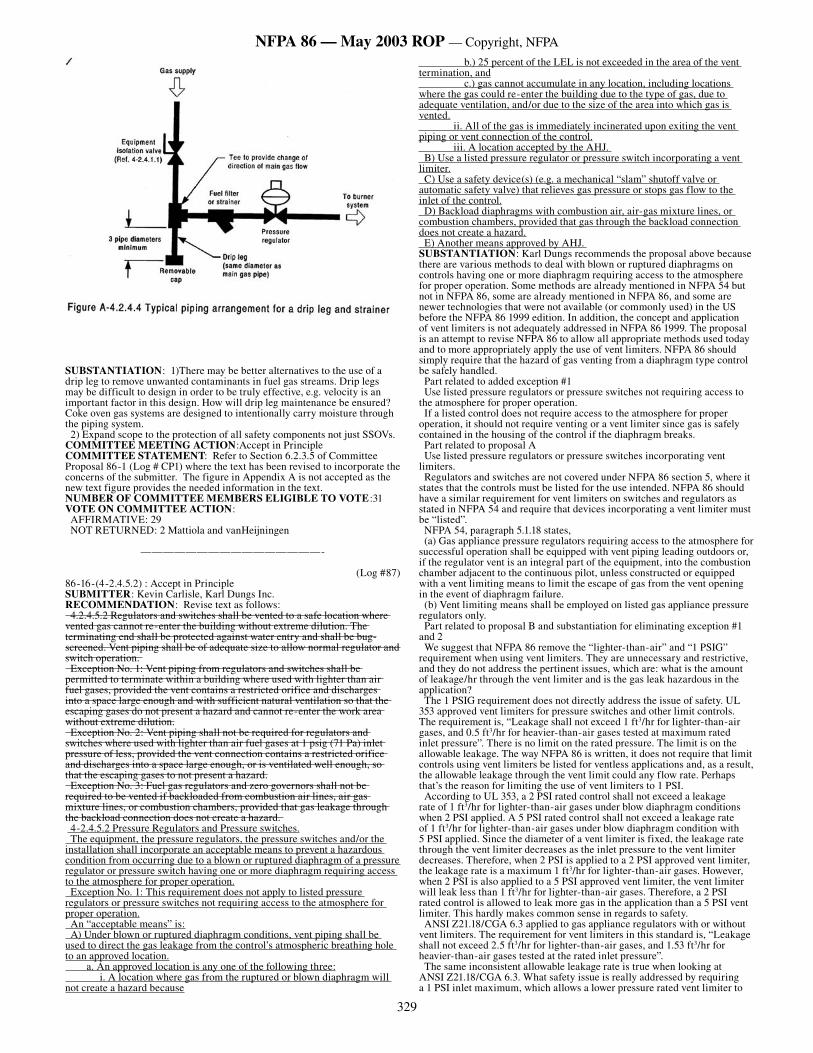
(Log #21)86-15-(4-2.4.3 and 4.2.4.4) : Accept in Principle SUBMITTER: Jim Houston, Industrial Heating Equipment Assn.RECOMMENDATION: Delete text as follows: 4-2.4.3* Fuel Filters and Strainers.For new installations, a gas filter or strainer shall be installed in the fuel gas piping to protect the downstream safety shutoff valves. 4-2.4.4* Drip Legs.A drip leg or sediment trap shall be installed for each fuel gas supply line prior to any piping devices. The drip leg shall be at least 3 in. (76 mm) long and the same diameter as the supply piping. Add text to read as follows: 4-2.4.3* Control of Contaminants. A coordinated approach shall be provided to protect components from contaminants. 4-2.4.3.1 Drip Legs. A drip leg shall be provided to remove unwanted heavy particulates and condensates to protect the downstream components. It shall be designed to provide a change in the direction of flow having a leg with a minimum length of 3 pipe diameters. It shall be located downstream of the equipment isolation valve. Exception: Other acceptable means to remove contaminants may be provided. 4-2.4.3.2 Fuel Filters and Strainers. A gas filter or strainer shall be installed in the fuel gas piping and located downstream of the equipment isolation valve and drip leg, and upstream of all other burner system components.
329
NFPA 86 — May 2003 ROP — Copyright, NFPA
SUBSTANTIATION: 1)There may be better alternatives to the use of a drip leg to remove unwanted contaminants in fuel gas streams. Drip legs may be difficult to design in order to be truly effective, e.g. velocity is an important factor in this design. How will drip leg maintenance be ensured? Coke oven gas systems are designed to intentionally carry moisture through the piping system. 2) Expand scope to the protection of all safety components not just SSOVs.COMMITTEE MEETING ACTION:Accept in PrincipleCOMMITTEE STATEMENT: Refer to Section 6.2.3.5 of Committee Proposal 86-1 (Log # CP1) where the text has been revised to incorporate the concerns of the submitter. The figure in Appendix A is not accepted as the new text figure provides the needed information in the text.NUMBER OF COMMITTEE MEMBERS ELIGIBLE TO VOTE:31VOTE ON COMMITTEE ACTION: AFFIRMATIVE: 29 NOT RETURNED: 2 Mattiola and vanHeijningen
————————————————-
(Log #87)86-16-(4-2.4.5.2) : Accept in Principle SUBMITTER: Kevin Carlisle, Karl Dungs Inc.RECOMMENDATION: Revise text as follows: 4.2.4.5.2 Regulators and switches shall be vented to a safe location where vented gas cannot re-enter the building without extreme dilution. The terminating end shall be protected against water entry and shall be bug-screened. Vent piping shall be of adequate size to allow normal regulator and switch operation. Exception No. 1: Vent piping from regulators and switches shall be permitted to terminate within a building where used with lighter than air fuel gases, provided the vent contains a restricted orifice and discharges into a space large enough and with sufficient natural ventilation so that the escaping gases do not present a hazard and cannot re-enter the work area without extreme dilution. Exception No. 2: Vent piping shall not be required for regulators and switches where used with lighter than air fuel gases at 1 psig (71 Pa) inlet pressure of less, provided the vent connection contains a restricted orifice and discharges into a space large enough, or is ventilated well enough, so that the escaping gases to not present a hazard. Exception No. 3: Fuel gas regulators and zero governors shall not be required to be vented if backloaded from combustion air lines, air gas mixture lines, or combustion chambers, provided that gas leakage through the backload connection does not create a hazard. 4-2.4.5.2 Pressure Regulators and Pressure switches. The equipment, the pressure regulators, the pressure switches and/or the installation shall incorporate an acceptable means to prevent a hazardous condition from occurring due to a blown or ruptured diaphragm of a pressure regulator or pressure switch having one or more diaphragm requiring access to the atmosphere for proper operation. Exception No. 1: This requirement does not apply to listed pressure regulators or pressure switches not requiring access to the atmosphere for proper operation. An “acceptable means” is: A) Under blown or ruptured diaphragm conditions, vent piping shall be used to direct the gas leakage from the control’s atmospheric breathing hole to an approved location. a. An approved location is any one of the following three: i. A location where gas from the ruptured or blown diaphragm will not create a hazard because
b.) 25 percent of the LEL is not exceeded in the area of the vent termination, and c.) gas cannot accumulate in any location, including locations where the gas could re-enter the building due to the type of gas, due to adequate ventilation, and/or due to the size of the area into which gas is vented. ii. All of the gas is immediately incinerated upon exiting the vent piping or vent connection of the control. iii. A location accepted by the AHJ. B) Use a listed pressure regulator or pressure switch incorporating a vent limiter. C) Use a safety device(s) (e.g. a mechanical “slam” shutoff valve or automatic safety valve) that relieves gas pressure or stops gas flow to the inlet of the control. D) Backload diaphragms with combustion air, air-gas mixture lines, or combustion chambers, provided that gas through the backload connection does not create a hazard. E) Another means approved by AHJ. SUBSTANTIATION: Karl Dungs recommends the proposal above because there are various methods to deal with blown or ruptured diaphragms on controls having one or more diaphragm requiring access to the atmosphere for proper operation. Some methods are already mentioned in NFPA 54 but not in NFPA 86, some are already mentioned in NFPA 86, and some are newer technologies that were not available (or commonly used) in the US before the NFPA 86 1999 edition. In addition, the concept and application of vent limiters is not adequately addressed in NFPA 86 1999. The proposal is an attempt to revise NFPA 86 to allow all appropriate methods used today and to more appropriately apply the use of vent limiters. NFPA 86 should simply require that the hazard of gas venting from a diaphragm type control be safely handled. Part related to added exception #1 Use listed pressure regulators or pressure switches not requiring access to the atmosphere for proper operation. If a listed control does not require access to the atmosphere for proper operation, it should not require venting or a vent limiter since gas is safely contained in the housing of the control if the diaphragm breaks. Part related to proposal A Use listed pressure regulators or pressure switches incorporating vent limiters. Regulators and switches are not covered under NFPA 86 section 5, where it states that the controls must be listed for the use intended. NFPA 86 should have a similar requirement for vent limiters on switches and regulators as stated in NFPA 54 and require that devices incorporating a vent limiter must be “listed”. NFPA 54, paragraph 5.1.18 states, (a) Gas appliance pressure regulators requiring access to the atmosphere for successful operation shall be equipped with vent piping leading outdoors or, if the regulator vent is an integral part of the equipment, into the combustion chamber adjacent to the continuous pilot, unless constructed or equipped with a vent limiting means to limit the escape of gas from the vent opening in the event of diaphragm failure. (b) Vent limiting means shall be employed on listed gas appliance pressure regulators only. Part related to proposal B and substantiation for eliminating exception #1 and 2 We suggest that NFPA 86 remove the “lighter-than-air” and “1 PSIG” requirement when using vent limiters. They are unnecessary and restrictive, and they do not address the pertinent issues, which are: what is the amount of leakage/hr through the vent limiter and is the gas leak hazardous in the application? The 1 PSIG requirement does not directly address the issue of safety. UL 353 approved vent limiters for pressure switches and other limit controls. The requirement is, “Leakage shall not exceed 1 ft3/hr for lighter-than-air gases, and 0.5 ft3/hr for heavier-than-air gases tested at maximum rated inlet pressure”. There is no limit on the rated pressure. The limit is on the allowable leakage. The way NFPA 86 is written, it does not require that limit controls using vent limiters be listed for ventless applications and, as a result, the allowable leakage through the vent limit could any flow rate. Perhaps that’s the reason for limiting the use of vent limiters to 1 PSI. According to UL 353, a 2 PSI rated control shall not exceed a leakage rate of 1 ft3/hr for lighter-than-air gases under blow diaphragm conditions when 2 PSI applied. A 5 PSI rated control shall not exceed a leakage rate of 1 ft3/hr for lighter-than-air gases under blow diaphragm condition with 5 PSI applied. Since the diameter of a vent limiter is fixed, the leakage rate through the vent limiter decreases as the inlet pressure to the vent limiter decreases. Therefore, when 2 PSI is applied to a 2 PSI approved vent limiter, the leakage rate is a maximum 1 ft3/hr for lighter-than-air gases. However, when 2 PSI is also applied to a 5 PSI approved vent limiter, the vent limiter will leak less than 1 ft3/hr for lighter-than-air gases. Therefore, a 2 PSI rated control is allowed to leak more gas in the application than a 5 PSI vent limiter. This hardly makes common sense in regards to safety. ANSI Z21.18/CGA 6.3 applied to gas appliance regulators with or without vent limiters. The requirement for vent limiters in this standard is, “Leakage shall not exceed 2.5 ft3/hr for lighter-than-air gases, and 1.53 ft3/hr for heavier-than-air gases tested at the rated inlet pressure”. The same inconsistent allowable leakage rate is true when looking at ANSI Z21.18/CGA 6.3. What safety issue is really addressed by requiring a 1 PSI inlet maximum, which allows a lower pressure rated vent limiter to
330
NFPA 86 — May 2003 ROP — Copyright, NFPA
leak more gas than a higher pressure rated vent limiter? If a vent limiter is approved for pressures higher than 1 PSI, why can’t it be used on systems built to NFPA 86 for pressures higher than 1 PSI? The inlet pressure should not restrict the use of a vent limiter. The main concern is the actually leakage rate of the vent limiter under blow diaphragm conditions. The allowable leakage for vent limiters is already covered in UL 353 and ANSI Z21.18/CGA 6.3, which inherently accommodated the maximum allowable leakage rate. Furthermore on the vent limiter discussion, NFPA 86 states discharges into a space large enough and with sufficient natural ventilation so that the escaping gases do not present a hazard and cannot re-enter the work area without extreme ventilation. This does address a safety issue. But, if proper ventilation is provided or enough natural ventilation exists, why can’t an approved vent limiter be used for system burning “heavier-than-air” fuel gases? “Heavier-than-air” fuel gas can be adequately and safety diluted and vented without accumulation. Part related to proposal C Use a safety device(s) (e.g. a mechanical “slam” shutoff valve or automatic safety valve) that relieves gas pressure or stops gas flow to the inlet of the control, which requires access to the atmosphere for proper operation. NFPA 54, 2.9.2 (5) defines a type of device used as an overpressure protection control. It states, “An automatic shutoff device installed in series with the service and line pressure regulator and set to shut off where the pressure on the downstream piping system reaches the maximum working pressure or some other predetermined pressure less than the maximum working pressure. This device shall be designed so that it will remain closed until manually reset.” Another method to safely handle controls having one of more diaphragm requiring access to the atmosphere for proper operations would be to mount the regulator downstream of an automatic or a mechanical safety shutoff valve (an automatic shutoff device as described in NFPA 54). In this case, if the diaphragm ruptures, an overpressure is detected and the upstream valve closes and stops gas flow and pressure to the control. In this case, gas only leaks from the control for a short time since the shutoff valve stop the flow of gas to the control. Part related to proposal D and substantiation for eliminating exception #3. Backload diaphragms with combustion air, air-gas mixture lines, or combustion chambers, provided that gas through the backload connection does not create a hazard. This is already covered in NFPA 86, paragraph 4-2.4.5.2, exception #3, it’s just moved to a different part of this section. Part related to proposal E Another means approved by AHJ. This should be added for applications or available appropriate methods not yet directly address in NFPA 86.COMMITTEE MEETING ACTION:Accept in PrincipleCOMMITTEE STATEMENT:Refer to committee draft, Committee Proposal 86-1 (Log # CP1), 6.2.5.5.3 where the additional items in the proposal are added.NUMBER OF COMMITTEE MEMBERS ELIGIBLE TO VOTE:31VOTE ON COMMITTEE ACTION: AFFIRMATIVE: 29 NOT RETURNED: 2 Mattiola and vanHeijningen
————————————————-
(Log #24)86-17-(4-3.4.1.6) : Accept in Principle SUBMITTER: Jim Houston, Industrial Heating Equipment Assn.RECOMMENDATION: Revise text to read as follows: 4-3.4.1.6* Valves and cocks shall be maintained and lubricated in accordance with the manufacturer’s instructions. Lubricated valves and cocks shall be lubricated at least annually. Add to Annex: A-4-3.4.1.6 Lubricated plug valves and cocks require lubrication with the proper lubricant to shut off tightly. The application and type of gas used may require frequent lubrication to maintain the ability of the valve to shutoff tightly when needed. SUBSTANTIATION: A recent investigation of a furnace explosion that killed a man…furnace was down for maintenance…30 to 35 PSIG gas pressure with 70 PSIG plant service pressure…caused by eroded lubricated plug valve…leaked through the pilot valves…filled the furnace with gas…welder outside of building near exhaust ignited the gas accumulation and was killed. COMMITTEE MEETING ACTION:Accept in PrincipleCOMMITTEE STATEMENT: Refer to Committee Proposal 86-1 (Log #CP1), 6.5.2.1.5 and 6.3.5.1.6 where the proposal has been incorporated.NUMBER OF COMMITTEE MEMBERS ELIGIBLE TO VOTE:31VOTE ON COMMITTEE ACTION: AFFIRMATIVE: 29 NOT RETURNED: 2 Mattiola and vanHeijningen
————————————————-
(Log #75)86-18-(5-2.3) : Reject SUBMITTER: Ted Jablkowski, P.E., North American Mfg. Co., Ltd.RECOMMENDATION: Revise text to read as follows: 5-2.3 Purge, ignition trials, and other burner safety sequencing shall be performed only by devices listed for such service. Discrete Purge, Ignition, Pilot Time Out and Purge Respond timers used in conjunction with combustion safeguards shall be safety devices listed for the service intended. SUBSTANTIATION: In some burner flame management systems, purge, ignition, pilot time out and purge respond timers are provided outside of the listed combustion safeguard. This is especially true in multi-burner systems. The proposed revision is to make the requirement for these timers clear. Please reference the separate proposal for Purge Respond timers under 5-4.1.2.4.COMMITTEE MEETING ACTION:RejectCOMMITTEE STATEMENT: The proposal is already covered in 7.2.1 and 7.2.3.NUMBER OF COMMITTEE MEMBERS ELIGIBLE TO VOTE:31VOTE ON COMMITTEE ACTION: AFFIRMATIVE: 29 NOT RETURNED: 2 Mattiola and vanHeijningen
————————————————-
(Log #41)86-19-(5-2.7 Exception No. 2) : Accept in Principle SUBMITTER: Jim Houston, Industrial Heating Equipment Assn.RECOMMENDATION: Revise text to read as follows: 5-2.7 All combustion safety circuitry contacts for required safety interlocks and excess temperature limit controllers shall be arranged in series ahead of the safety shutoff valve holding medium.Exception No. 1: Devices specifically listed for combustion safety service shall be permitted to be used in accordance with the listing requirements and the manufacturer’s instructions.Exception No. 2: Interposing relays may be of the general purpose type and shall be permitted where the conditions of (a), (b), and (c) are met: (a) Required connected load exceeds the rating of available safety interlock devices or where necessary to perform required safety logic functions (b) Interposing relay is configured to revert to a safe condition upon loss of power (c) Each interposing relay serves no more than one safety interlock device SUBSTANTIATION: The exception under 5-2.7 is not clear in its requirement for the type of relays required for this purpose. If the intent of the standard is to require the use of listed interposing relays in compliance with 5-2.1, please identify them. COMMITTEE MEETING ACTION:Accept in PrincipleCOMMITTEE STATEMENT: Refer to committee draft, Committee Proposal 86-1 (Log #CP1 ), 7.2.7 where the intent of the proposal is included. NUMBER OF COMMITTEE MEMBERS ELIGIBLE TO VOTE:31VOTE ON COMMITTEE ACTION: AFFIRMATIVE: 29 NOT RETURNED: 2 Mattiola and vanHeijningen
————————————————-
(Log #25)86-20-(5-4.1.2.1) : Accept in Principle SUBMITTER: Jim Houston, Industrial Heating Equipment Assn.RECOMMENDATION: Revise text to read as follows: 5-4.1.2.1 To begin the timed preignition purge interval, both of the following conditions shall be satisfied: (1) The minimum required preignition airflow shall be proven (see Sections 5-5 and 5-6 for proof of airflow requirements). (2)The safety shutoff valve(s) shall be proved closed (see 5-7.2.2 and 5-7.3.2 for proof of closure proved closed requirements).SUBSTANTIATION: To be consistent with use of proved closed elsewhere in the standard.COMMITTEE MEETING ACTION:Accept in PrincipleCOMMITTEE STATEMENT: Refer to committee draft, Proposal 86-1 (Log #CP1), 7.4.1.2.1NUMBER OF COMMITTEE MEMBERS ELIGIBLE TO VOTE:31VOTE ON COMMITTEE ACTION: AFFIRMATIVE: 29 NOT RETURNED: 2 Mattiola and vanHeijningen
————————————————-
(Log #71)86-21-(5-4.1.2.4) : Accept in Principle SUBMITTER: Ted Jablkowski, P.E., North American Mfg. Co., Ltd.RECOMMENDATION: Add new text to read as follows: 5-4.1.2.4 A respond timer shall be used to limit the amount of time between purge complete and the trial for ignition. SUBSTANTIATION: In burner flame management systems, component failures can result in an unwanted delay in the trail for ignition following the completion of purge.COMMITTEE MEETING ACTION:Accept in Principle
331
NFPA 86 — May 2003 ROP — Copyright, NFPA
COMMITTEE STATEMENT: Refer to committee draft, Committee Comment 86-1 (Log #CP1), A-7.4.2. The concept is added to the appendix as the proposed text does not apply to all ovens.NUMBER OF COMMITTEE MEMBERS ELIGIBLE TO VOTE:31VOTE ON COMMITTEE ACTION: AFFIRMATIVE: 29 NOT RETURNED: 2 Mattiola and vanHeijningen
————————————————-
(Log #3)86-22-(5-4.1.5) : Reject NOTE: This Proposal appeared as Comment 86-15 (Log #28) which was held from the May 1999 ROC on Proposal 86-1.SUBMITTER: Peter J. Willse, HSB Industrial Risk InsurersRECOMMENDATION: Add to the end of 5-4.1.5 the following: The volume of air for the preignition purge, as required in 5-4.1.2 shall be referred to 70°F (21°C) (See Table 7-4.1). SUBSTANTIATION: At elevated temperatures, the required volume of air for a prepurge is much higher then for a prepurge of a cold oven or furnace as required in 5-4.1.2. If the oven was operating a 600°F, the volume of air for the purge will be half of the volume for a cold oven.COMMITTEE MEETING ACTION:RejectCOMMITTEE STATEMENT: The proponent is correct that the mass of air changes with temperature. The committee notes that the dilution during purging is unchanged with temperature. NUMBER OF COMMITTEE MEMBERS ELIGIBLE TO VOTE:31VOTE ON COMMITTEE ACTION: AFFIRMATIVE: 29 NOT RETURNED: 2 Mattiola and vanHeijningen
————————————————-
(Log #80)86-23-(5-6.2) : Accept in Principle SUBMITTER: Ted Jablkowski, P.E., North American Mfg. Co., Ltd.RECOMMENDATION: Revise text to read as follows: 5-6.2 Where a combustion air blower is used, the minimum combustion air flow or source pressure needed for proper burner operation shall be proven prior to each attempt at ignition. SUBSTANTIATION: The existing language is not clear with respect to requiring the assurance of either a minimum air flow or air pressure. In today’s industrial combustion applications with modulating flow control valves downstream of the combustion air blower, it is most common to interlock the constant combustion air source pressure on single and multi-burner systems to meet the requirements of 5-6.2. Since the combustion air flow is proven during each purge cycle along with the combustion air source pressure, the most common convention is to prove the combustion air source pressure during burner operation following purge. In a multi-burner system, the proof of combustion air flow during purge proves that any manual valves in the combustion air system are in an adequately open position. These manual air valves are provided for maintenance and combustion air flow balancing among burners in a temperature control zone. In combustion air supply systems that use either an inlet damper or speed control, the combustion air pressure may fall below reliably repeatable levels with listed pressure switch interlocks at low fire. For these systems, the proof of minimum air flow may be a more reliable interlock. COMMITTEE MEETING ACTION:Accept in PrincipleCOMMITTEE STATEMENT: Refer to committee draft, Committee Proposal 86-1 (Log #CP1), 7.6.2 where the proposal has been incorporated.NUMBER OF COMMITTEE MEMBERS ELIGIBLE TO VOTE:31VOTE ON COMMITTEE ACTION: AFFIRMATIVE: 28 NEGATIVE: 1 NOT RETURNED: 2 Mattiola and vanHeijningenEXPLANATION OF NEGATIVE: COLLIER: With the use of “or” (grammatical structure), this addition implies acceptance of monitoring only air source pressure, which can be upstream of the flow regulating devices. A system where proof of minimum required airflow is necessary will not be protected. The original wording is fine as originally stated. It would be better to add an appendix with the text of the substantiation. Note also that proving may involve a damper position switch in combination with the source pressure switch.
————————————————-
(Log #79)86-24-(5-6.4) : Accept in Principle SUBMITTER: Ted Jablkowski, P.E., North American Mfg. Co., Ltd.RECOMMENDATION: Revise text to read as follows: 5-6.4* A low pressure switch shall be used to sense and monitor the combustion air source pressure or a differential pressure switch sensing the differential pressure across a fixed orifice in the combustion air system or an air flow interlock shall be interlocked into the combustion safety circuitry. Exception: Alternative methods of verification of minimum combustion air flow or source pressure required for burner operation shall be permitted where both of the following conditions are satisfied.
(a) The burner can reliably operate at a combustion air pressure that is lower than the available range of pressure switches listed for this service. (b) The alternative method is acceptable to the authority having jurisdiction. SUBSTANTIATION: The existing language is not clear with respect to requiring the assurance of either a minimum air flow, via a differential pressure, or air pressure, assumed to be a static pressure. In today’s industrial combustion applications with modulating flow control valves downstream of the combustion air blower, it is most common to interlock the constant combustion air source pressure on single and multi-burner systems to meet the requirements of 5-6.2 and 5-6.4. Since the combustion air flow is proven during each purge cycle along with the combustion air source pressure, the most common convention is to prove the combustion air source pressure during burner operation following purge. In a multi-burner system, the proof of combustion air flow during purge proves that any manual valves in the combustion air system are in an adequately open position. These manual air valves are provided for maintenance and combustion air flow balancing among burners in a temperature control zone. In combustion air supply systems that use either an inlet damper or speed control, the combustion air pressure may fall below reliably repeatable levels with listed pressure switch interlocks at low fire. For these systems, the proof of minimum air flow may be a more reliable interlock.COMMITTEE MEETING ACTION:Accept in PrincipleCOMMITTEE STATEMENT: Refer to committee draft, Committee Proposal 86-1 (Log # CP1), 7.6.4 where the text is revised to clarify it.NUMBER OF COMMITTEE MEMBERS ELIGIBLE TO VOTE:31VOTE ON COMMITTEE ACTION: AFFIRMATIVE: 29 NOT RETURNED: 2 Mattiola and vanHeijningen
————————————————-
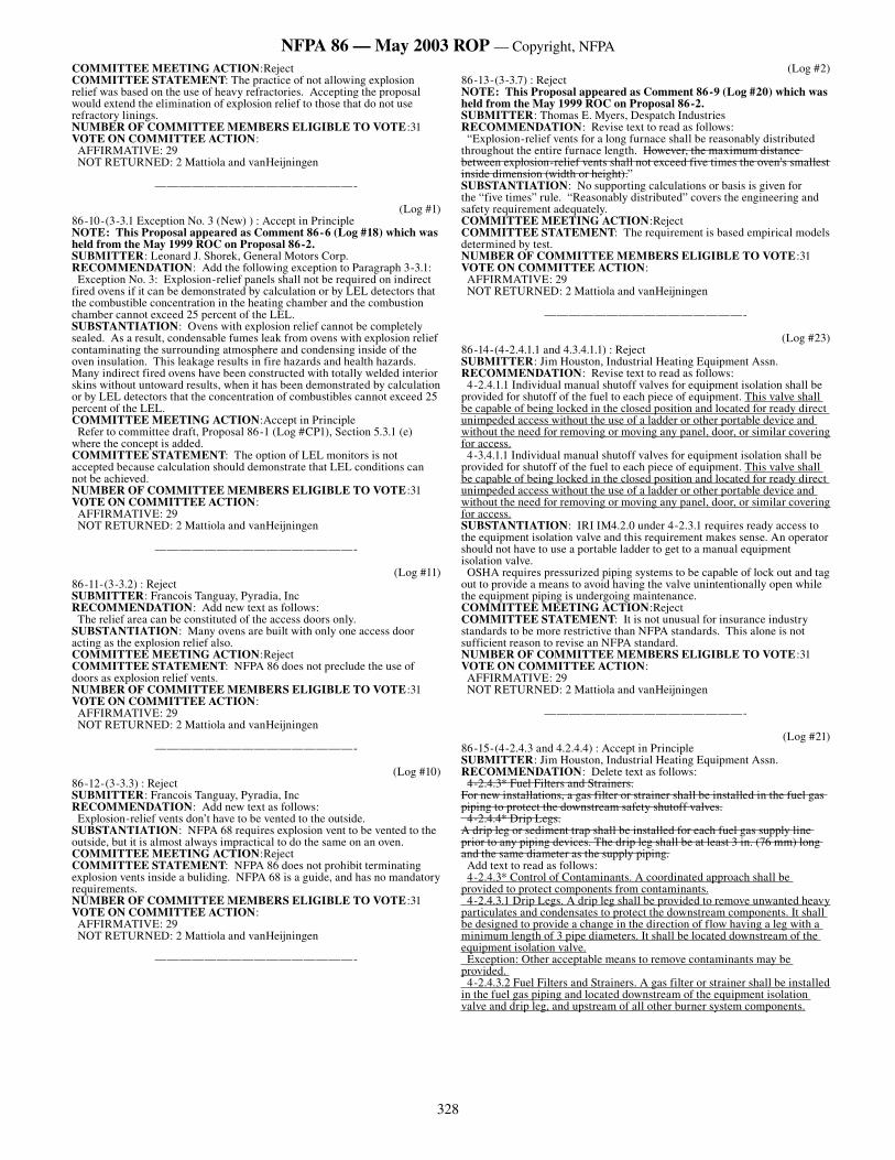
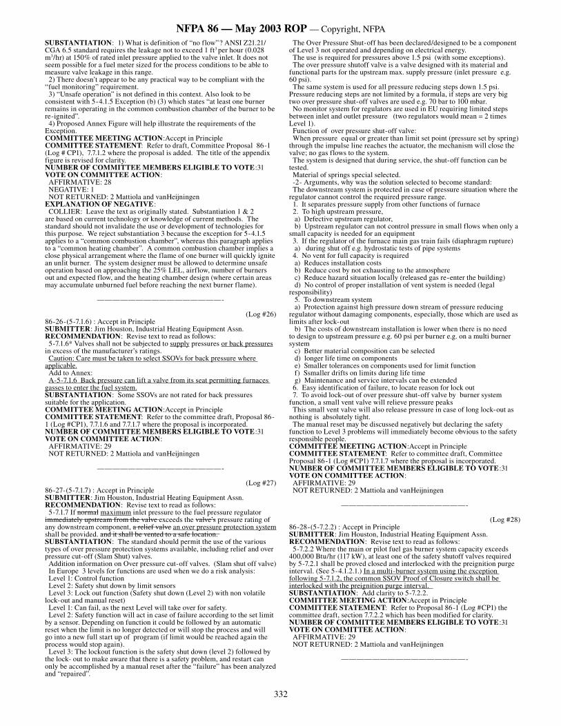
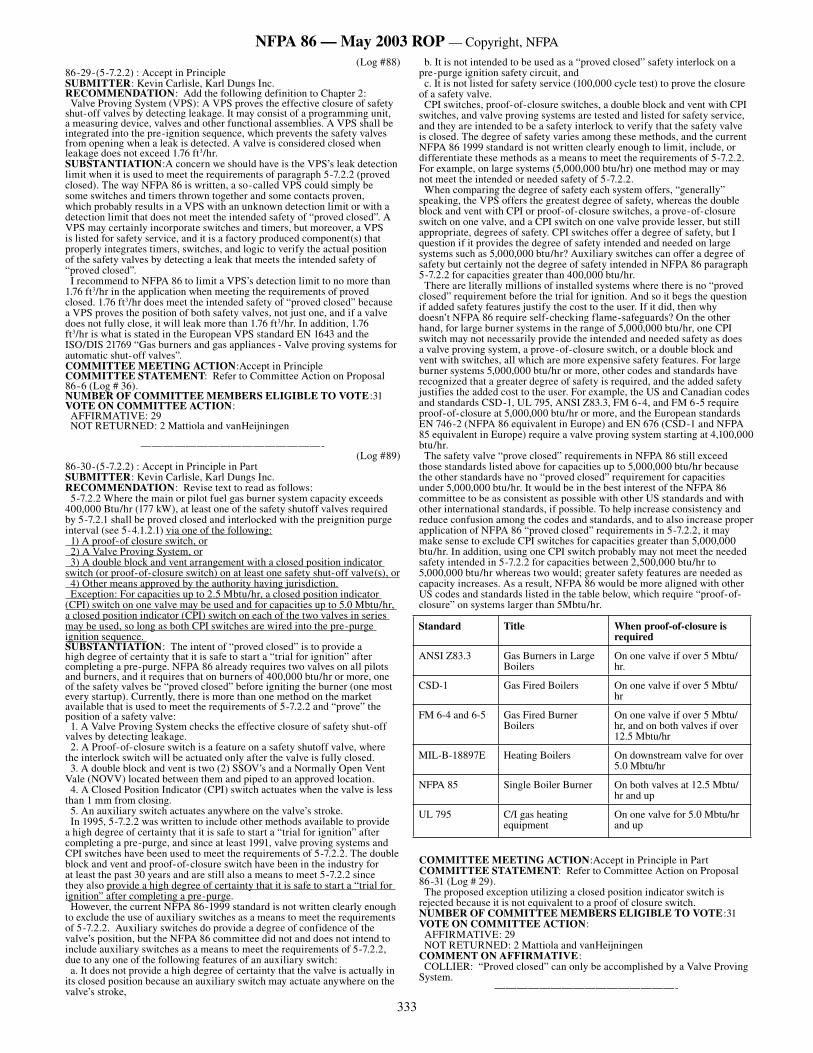
(Log #31)86-25-(5-7.1.2 Exceptionand Figure A-5-7.1.2) : Accept in Principle SUBMITTER: Jim Houston, Industrial Heating Equipment Assn.RECOMMENDATION: Revise Exception to 5-7.1.2 as follows: Exception: For fuel gas systems, where multiple burners or pilots operate as a burner system firing into a common heating chamber, the loss of flame signal at one or more burners shall be permitted to shut off those burner(s) by closing a single safety shutoff valve, provided the following conditions in both (a) and (b) are satisfied. (a) For the individual burner safety shutoff valve (1) it is demonstrated based on available airflow that failure of the valve to close will result in a fuel concentration not greater than 25 percent of the LEL; or (2) the safety shutoff valve has proof of closure acceptable to the authority having jurisdiction; or (3) the fuel to the burner is monitored to verify that there is no fuel flow following operation of the burner safety shutoff valve. (b) The safety shutoff valve upstream of the individual burner safety shutoff valves shall close for any of the following conditions: (1) activation of any operating control or interlocking safety device other than the combustion safeguard; or (2) when the individual burner valves do not have proof of closure or fuel monitoring as described in (a) and the number of failed burners are capable of exceeding 25 percent of the LEL if their single safety shutoff valves should fail in the open position; or (3) when individual burner valves have proof of closure or fuel monitoring as described in (a) and verification that the individual burner safety shutoff valve has closed following loss of flame signal at the burner is not present; or (4) loss of flame signal at all burners in the burner system or at a number of burners in the burner system that will result in unsafe operation. Add to Annex: Figure A-5-7.1.2
Figure A-5-7.1.2 Exception for multiple burner system using proof of closure switches as per 5-7.1.2 (a) 2 and (b) 3
����������������
�������������������
���������������
�����������������������������
����������������������������������������
�� ���������������������������������������� ����������������������������������������������
�����������
��������������������
�����������
����������
������
�����������
332
NFPA 86 — May 2003 ROP — Copyright, NFPA
SUBSTANTIATION: 1) What is definition of “no flow”? ANSI Z21.21/CGA 6.5 standard requires the leakage not to exceed 1 ft3 per hour (0.028 m3/hr) at 150% of rated inlet pressure applied to the valve inlet. It does not seem possible for a fuel meter sized for the process conditions to be able to measure valve leakage in this range. 2) There doesn’t appear to be any practical way to be compliant with the “fuel monitoring” requirement. 3) “Unsafe operation” is not defined in this context. Also look to be consistent with 5-4.1.5 Exception (b) (3) which states “at least one burner remains in operating in the common combustion chamber of the burner to be re-ignited”. 4) Proposed Annex Figure will help illustrate the requirements of the Exception. COMMITTEE MEETING ACTION:Accept in PrincipleCOMMITTEE STATEMENT: Refer to draft, Committee Proposal 86-1 (Log # CP1), 7.7.1.2 where the proposal is added. The title of the appendix figure is revised for clarity.NUMBER OF COMMITTEE MEMBERS ELIGIBLE TO VOTE:31VOTE ON COMMITTEE ACTION: AFFIRMATIVE: 28 NEGATIVE: 1 NOT RETURNED: 2 Mattiola and vanHeijningenEXPLANATION OF NEGATIVE: COLLIER: Leave the text as originally stated. Substantiation 1 & 2 are based on current technology or knowledge of current methods. The standard should not invalidate the use or development of technologies for this purpose. We reject substantiation 3 because the exception for 5-4.1.5 applies to a “common combustion chamber”, whereas this paragraph applies to a “common heating chamber”. A common combustion chamber implies a close physical arrangement where the flame of one burner will quickly ignite an unlit burner. The system designer must be allowed to determine unsafe operation based on approaching the 25% LEL, airflow, number of burners out and expected flow, and the heating chamber design (where certain areas may accumulate unburned fuel before reaching the next burner flame).
————————————————-
(Log #26)86-26-(5-7.1.6) : Accept in Principle SUBMITTER: Jim Houston, Industrial Heating Equipment Assn.RECOMMENDATION: Revise text to read as follows: 5-7.1.6* Valves shall not be subjected to supply pressures or back pressures in excess of the manufacturer’s ratings. Caution: Care must be taken to select SSOVs for back pressure where applicable. Add to Annex: A-5-7.1.6 Back pressure can lift a valve from its seat permitting furnaces gasses to enter the fuel system.SUBSTANTIATION: Some SSOVs are not rated for back pressures suitable for the application.COMMITTEE MEETING ACTION:Accept in PrincipleCOMMITTEE STATEMENT: Refer to the committee draft, Proposal 86-1 (Log #CP1), 7.7.1.6 and 7.7.1.7 where the proposal is incorporated.NUMBER OF COMMITTEE MEMBERS ELIGIBLE TO VOTE:31VOTE ON COMMITTEE ACTION: AFFIRMATIVE: 29 NOT RETURNED: 2 Mattiola and vanHeijningen
————————————————-
(Log #27)86-27-(5-7.1.7) : Accept in Principle SUBMITTER: Jim Houston, Industrial Heating Equipment Assn.RECOMMENDATION: Revise text to read as follows: 5-7.1.7 If normal maximum inlet pressure to the fuel pressure regulator immediately upstream from the valve exceeds the valve’s pressure rating of any downstream component, a relief valve an over pressure protection system shall be provided. and it shall be vented to a safe location. SUBSTANTIATION: The standard should permit the use of the various types of over pressure protection systems available, including relief and over pressure cut-off (Slam Shut) valves. Addition information on Over pressure cut-off valves. (Slam shut off valve) In Europe 3 levels for functions are used when we do a risk analysis: Level 1: Control function Level 2: Safety shut down by limit sensors Level 3: Lock out function (Safety shut down (Level 2) with non volatile lock-out and manual reset) Level 1: Can fail, as the next Level will take over for safety. Level 2: Safety function will act in case of failure according to the set limit by a sensor. Depending on function it could be followed by an automatic reset when the limit is no longer detected or will stop the process and will go into a new full start up of program (if limit would be reached again the process would stop again). Level 3: The lockout function is the safety shut down (level 2) followed by the lock- out to make aware that there is a safety problem, and restart can only be accomplished by a manual reset after the “failure” has been analyzed and “repaired”.
The Over Pressure Shut-off has been declared/designed to be a component of Level 3 not operated and depending on electrical energy. The use is required for pressures above 1.5 psi (with some exceptions). The over pressure shutoff valve is a valve designed with its material and functional parts for the upstream max. supply pressure (inlet pressure e.g. 60 psi). The same system is used for all pressure reducing steps down 1.5 psi. Pressure reducing steps are not limited by a formula, if steps are very big two over pressure shut-off valves are used e.g. 70 bar to 100 mbar. No monitor system for regulators are used in EU requiring limited steps between inlet and outlet pressure (two regulators would mean = 2 times Level 1). Function of over pressure shut-off valve: When pressure equal or greater than limit set point (pressure set by spring) through the impulse line reaches the actuator, the mechanism will close the valve; no gas flows to the system. The system is designed that during service, the shut-off function can be tested. Material of springs special selected. -2- Arguments, why was the solution selected to become standard: The downstream system is protected in case of pressure situation where the regulator cannot control the required pressure range. 1. It separates pressure supply from other functions of furnace 2. To high upstream pressure, a) Defective upstream regulator, b) Upstream regulator can not control pressure in small flows when only a small capacity is needed for an equipment 3. If the regulator of the furnace main gas train fails (diaphragm rupture) a) during shut off e.g. hydrostatic tests of pipe systems 4. No vent for full capacity is required a) Reduces installation costs b) Reduce cost by not exhausting to the atmosphere c) Reduce hazard situation locally (released gas re-enter the building) d) No control of proper installation of vent system is needed (legal responsibility) 5. To downstream system a) Protection against high pressure down stream of pressure reducing regulator without damaging components, especially, those which are used as limits after lock-out b) The costs of downstream installation is lower when there is no need to design to upstream pressure e.g. 60 psi per burner e.g. on a multi burner system c) Better material composition can be selected d) longer life time on components e) Smaller tolerances on components used for limit function f) Ssmaller drifts on limits during life time g) Maintenance and service intervals can be extended 6. Easy identification of failure, to locate reason for lock out 7. To avoid lock-out of over pressure shut-off valve by burner system function, a small vent valve will relieve pressure peaks This small vent valve will also release pressure in case of long lock-out as nothing is absolutely tight. The manual reset may be discussed negatively but declaring the safety function to Level 3 problems will immediately become obvious to the safety responsible people.COMMITTEE MEETING ACTION:Accept in PrincipleCOMMITTEE STATEMENT: Refer to committee draft, Committee Proposal 86-1 (Log #CP1) 7.7.1.7 where the proposal is incorporated.NUMBER OF COMMITTEE MEMBERS ELIGIBLE TO VOTE:31VOTE ON COMMITTEE ACTION: AFFIRMATIVE: 29 NOT RETURNED: 2 Mattiola and vanHeijningen
————————————————-
(Log #28)86-28-(5-7.2.2) : Accept in Principle SUBMITTER: Jim Houston, Industrial Heating Equipment Assn.RECOMMENDATION: Revise text to read as follows: 5-7.2.2 Where the main or pilot fuel gas burner system capacity exceeds 400,000 Btu/hr (117 kW), at least one of the safety shutoff valves required by 5-7.2.1 shall be proved closed and interlocked with the preignition purge interval. (See 5-4.1.2.1.) In a multi-burner system using the exception following 5-7.1.2, the common SSOV Proof of Closure switch shall be interlocked with the preignition purge interval. SUBSTANTIATION: Add clarity to 5-7.2.2.COMMITTEE MEETING ACTION:Accept in PrincipleCOMMITTEE STATEMENT: Refer to Proposal 86-1 (Log #CP1) the committee draft, section 7.7.2.2 which has been modified for clarity. NUMBER OF COMMITTEE MEMBERS ELIGIBLE TO VOTE:31VOTE ON COMMITTEE ACTION: AFFIRMATIVE: 29 NOT RETURNED: 2 Mattiola and vanHeijningen
————————————————-
333
NFPA 86 — May 2003 ROP — Copyright, NFPA
(Log #88)86-29-(5-7.2.2) : Accept in Principle SUBMITTER: Kevin Carlisle, Karl Dungs Inc.RECOMMENDATION: Add the following definition to Chapter 2: Valve Proving System (VPS): A VPS proves the effective closure of safety shut-off valves by detecting leakage. It may consist of a programming unit, a measuring device, valves and other functional assemblies. A VPS shall be integrated into the pre-ignition sequence, which prevents the safety valves from opening when a leak is detected. A valve is considered closed when leakage does not exceed 1.76 ft3/hr. SUBSTANTIATION:A concern we should have is the VPS’s leak detection limit when it is used to meet the requirements of paragraph 5-7.2.2 (proved closed). The way NFPA 86 is written, a so-called VPS could simply be some switches and timers thrown together and some contacts proven, which probably results in a VPS with an unknown detection limit or with a detection limit that does not meet the intended safety of “proved closed”. A VPS may certainly incorporate switches and timers, but moreover, a VPS is listed for safety service, and it is a factory produced component(s) that properly integrates timers, switches, and logic to verify the actual position of the safety valves by detecting a leak that meets the intended safety of “proved closed”. I recommend to NFPA 86 to limit a VPS’s detection limit to no more than 1.76 ft3/hr in the application when meeting the requirements of proved closed. 1.76 ft3/hr does meet the intended safety of “proved closed” because a VPS proves the position of both safety valves, not just one, and if a valve does not fully close, it will leak more than 1.76 ft3/hr. In addition, 1.76 ft3/hr is what is stated in the European VPS standard EN 1643 and the ISO/DIS 21769 “Gas burners and gas appliances - Valve proving systems for automatic shut-off valves”.COMMITTEE MEETING ACTION:Accept in PrincipleCOMMITTEE STATEMENT: Refer to Committee Action on Proposal 86-6 (Log # 36).NUMBER OF COMMITTEE MEMBERS ELIGIBLE TO VOTE:31VOTE ON COMMITTEE ACTION: AFFIRMATIVE: 29 NOT RETURNED: 2 Mattiola and vanHeijningen
————————————————-(Log #89)
86-30-(5-7.2.2) : Accept in Principle in Part SUBMITTER: Kevin Carlisle, Karl Dungs Inc.RECOMMENDATION: Revise text to read as follows: 5-7.2.2 Where the main or pilot fuel gas burner system capacity exceeds 400,000 Btu/hr (177 kW), at least one of the safety shutoff valves required by 5-7.2.1 shall be proved closed and interlocked with the preignition purge interval (see 5-4.1.2.1) via one of the following: 1) A proof-of closure switch, or 2) A Valve Proving System, or 3) A double block and vent arrangement with a closed position indicator switch (or proof-of-closure switch) on at least one safety shut-off valve(s), or 4) Other means approved by the authority having jurisdiction. Exception: For capacities up to 2.5 Mbtu/hr, a closed position indicator (CPI) switch on one valve may be used and for capacities up to 5.0 Mbtu/hr, a closed position indicator (CPI) switch on each of the two valves in series may be used, so long as both CPI switches are wired into the pre-purge ignition sequence. SUBSTANTIATION: The intent of “proved closed” is to provide a high degree of certainty that it is safe to start a “trial for ignition” after completing a pre-purge. NFPA 86 already requires two valves on all pilots and burners, and it requires that on burners of 400,000 btu/hr or more, one of the safety valves be “proved closed” before igniting the burner (one most every startup). Currently, there is more than one method on the market available that is used to meet the requirements of 5-7.2.2 and “prove” the position of a safety valve: 1. A Valve Proving System checks the effective closure of safety shut-off valves by detecting leakage. 2. A Proof-of-closure switch is a feature on a safety shutoff valve, where the interlock switch will be actuated only after the valve is fully closed. 3. A double block and vent is two (2) SSOV’s and a Normally Open Vent Vale (NOVV) located between them and piped to an approved location. 4. A Closed Position Indicator (CPI) switch actuates when the valve is less than 1 mm from closing. 5. An auxiliary switch actuates anywhere on the valve’s stroke. In 1995, 5-7.2.2 was written to include other methods available to provide a high degree of certainty that it is safe to start a “trial for ignition” after completing a pre-purge, and since at least 1991, valve proving systems and CPI switches have been used to meet the requirements of 5-7.2.2. The double block and vent and proof-of-closure switch have been in the industry for at least the past 30 years and are still also a means to meet 5-7.2.2 since they also provide a high degree of certainty that it is safe to start a “trial for ignition” after completing a pre-purge. However, the current NFPA 86-1999 standard is not written clearly enough to exclude the use of auxiliary switches as a means to meet the requirements of 5-7.2.2. Auxiliary switches do provide a degree of confidence of the valve’s position, but the NFPA 86 committee did not and does not intend to include auxiliary switches as a means to meet the requirements of 5-7.2.2, due to any one of the following features of an auxiliary switch: a. It does not provide a high degree of certainty that the valve is actually in its closed position because an auxiliary switch may actuate anywhere on the valve’s stroke,
b. It is not intended to be used as a “proved closed” safety interlock on a pre-purge ignition safety circuit, and c. It is not listed for safety service (100,000 cycle test) to prove the closure of a safety valve. CPI switches, proof-of-closure switches, a double block and vent with CPI switches, and valve proving systems are tested and listed for safety service, and they are intended to be a safety interlock to verify that the safety valve is closed. The degree of safety varies among these methods, and the current NFPA 86 1999 standard is not written clearly enough to limit, include, or differentiate these methods as a means to meet the requirements of 5-7.2.2. For example, on large systems (5,000,000 btu/hr) one method may or may not meet the intended or needed safety of 5-7.2.2. When comparing the degree of safety each system offers, “generally” speaking, the VPS offers the greatest degree of safety, whereas the double block and vent with CPI or proof-of-closure switches, a prove-of-closure switch on one valve, and a CPI switch on one valve provide lesser, but still appropriate, degrees of safety. CPI switches offer a degree of safety, but I question if it provides the degree of safety intended and needed on large systems such as 5,000,000 btu/hr? Auxiliary switches can offer a degree of safety but certainly not the degree of safety intended in NFPA 86 paragraph 5-7.2.2 for capacities greater than 400,000 btu/hr. There are literally millions of installed systems where there is no “proved closed” requirement before the trial for ignition. And so it begs the question if added safety features justify the cost to the user. If it did, then why doesn’t NFPA 86 require self-checking flame-safeguards? On the other hand, for large burner systems in the range of 5,000,000 btu/hr, one CPI switch may not necessarily provide the intended and needed safety as does a valve proving system, a prove-of-closure switch, or a double block and vent with switches, all which are more expensive safety features. For large burner systems 5,000,000 btu/hr or more, other codes and standards have recognized that a greater degree of safety is required, and the added safety justifies the added cost to the user. For example, the US and Canadian codes and standards CSD-1, UL 795, ANSI Z83.3, FM 6-4, and FM 6-5 require proof-of-closure at 5,000,000 btu/hr or more, and the European standards EN 746-2 (NFPA 86 equivalent in Europe) and EN 676 (CSD-1 and NFPA 85 equivalent in Europe) require a valve proving system starting at 4,100,000 btu/hr. The safety valve “prove closed” requirements in NFPA 86 still exceed those standards listed above for capacities up to 5,000,000 btu/hr because the other standards have no “proved closed” requirement for capacities under 5,000,000 btu/hr. It would be in the best interest of the NFPA 86 committee to be as consistent as possible with other US standards and with other international standards, if possible. To help increase consistency and reduce confusion among the codes and standards, and to also increase proper application of NFPA 86 “proved closed” requirements in 5-7.2.2, it may make sense to exclude CPI switches for capacities greater than 5,000,000 btu/hr. In addition, using one CPI switch probably may not meet the needed safety intended in 5-7.2.2 for capacities between 2,500,000 btu/hr to 5,000,000 btu/hr whereas two would; greater safety features are needed as capacity increases. As a result, NFPA 86 would be more aligned with other US codes and standards listed in the table below, which require “proof-of-closure” on systems larger than 5Mbtu/hr.
COMMITTEE MEETING ACTION:Accept in Principle in PartCOMMITTEE STATEMENT: Refer to Committee Action on Proposal 86-31 (Log # 29). The proposed exception utilizing a closed position indicator switch is rejected because it is not equivalent to a proof of closure switch. NUMBER OF COMMITTEE MEMBERS ELIGIBLE TO VOTE:31VOTE ON COMMITTEE ACTION: AFFIRMATIVE: 29 NOT RETURNED: 2 Mattiola and vanHeijningenCOMMENT ON AFFIRMATIVE: COLLIER: “Proved closed” can only be accomplished by a Valve Proving System.
————————————————-
Standard Title When proof-of-closure is required
ANSI Z83.3 Gas Burners in Large Boilers
On one valve if over 5 Mbtu/hr.
CSD-1 Gas Fired Boilers On one valve if over 5 Mbtu/hr
FM 6-4 and 6-5 Gas Fired Burner Boilers
On one valve if over 5 Mbtu/hr, and on both valves if over 12.5 Mbtu/hr
MIL-B-18897E Heating Boilers On downstream valve for over 5.0 Mbtu/hr
NFPA 85 Single Boiler Burner On both valves at 12.5 Mbtu/hr and up
UL 795 C/I gas heating equipment
On one valve for 5.0 Mbtu/hr and up
334
NFPA 86 — May 2003 ROP — Copyright, NFPA
(Log #29)86-31-(5-7.2.2 and A-5-7.2.2 (New) ) : Accept in Principle in Part SUBMITTER: Jim Houston, Industrial Heating Equipment Assn.RECOMMENDATION: New Proposal to add to 5-7.2.2*: 5-7.2.2* Where the main or pilot fuel gas burner system capacity exceeds 400,000 Btu/hr (117 kW), at least one of the safety shutoff valves required by 5-7.2.1 shall be proved closed and interlocked with the preignition purge interval. (See 5-4.1.2.1.) Proved Closed shall be accomplished by any of the following means: 1) Two (2) SSOVs, one (1) equipped with a Proof of Closure switch 2) Two (2) SSOVs equipped with a Valve Proving System 3) For lighter than air gasses only, two (2) SSOVs each with a Closed Position Indicator switch and with a Normally Open Vent Valve located between them and piped to an approved location. 4) Other approved means Suggested Annex material A-5-7.2.2: A-5-7.2.2 A NO vent should not be used on heavier than air (propane) gases or where it may not be allowed by the Authority Having Jurisdiction. A Proof of Closure Switch may be used in place of a Closed Position Indicator Switch but not visa versa.SUBSTANTIATION: It is our understanding at IHEA, that the 1995 NFPA 86 change from Proof of Closure to Proved Closed was intended to allow other methods, like Valve Proving Systems, to be used. It was not intended to permit the use of auxiliary switches that could be adjusted to trip at any point in the valve stroke to be used as a means to prove the valve is closed. Closed Position Indicator switch is a term defined in the prEN 161 Standard that describes the limits of its setting with regard to the valve seat opening. A separate proposal will be made for this definition.COMMITTEE MEETING ACTION:Accept in Principle in PartCOMMITTEE STATEMENT: The option of two valves each with a CPI switch with a normally open vent is not equivalent to proof of closure. No substantiation was submitted to support this. NUMBER OF COMMITTEE MEMBERS ELIGIBLE TO VOTE:31VOTE ON COMMITTEE ACTION: AFFIRMATIVE: 29 NOT RETURNED: 2 Mattiola and vanHeijningenCOMMENT ON AFFIRMATIVE: COLLIER: “Proved closed” can only be accomplished by a Valve Proving System.
————————————————-
(Log #8)86-32-(5-7.2.4) : Reject SUBMITTER: Paul R. Vaulman, Eclipse Combustion, Inc.RECOMMENDATION: Revise text to read as follows: “Tightness checks shall be performed in accordance with the manufacturer’s instructions. by applying the maximum operating pressure of the system across the valve. Take action in accordance with the manufacturer’s instructions if leakage is detected. SUBSTANTIATION: Manufacturer’s published instructions do not include details on performing leak tests nor are they required to by the approval agencies such as UL, FM or CSA. Leak testing is a system function which is governed by NFPA. Establishing test pressures at the valve level would put components with lower rated pressures at risk.COMMITTEE MEETING ACTION:RejectCOMMITTEE STATEMENT: The test should be done at the normal operating pressure, not the maximum operating pressure, NUMBER OF COMMITTEE MEMBERS ELIGIBLE TO VOTE:31VOTE ON COMMITTEE ACTION: AFFIRMATIVE: 29 NOT RETURNED: 2 Mattiola and vanHeijningen
————————————————-
(Log #30)86-33-(5-7.2.4, Figure A-5.7.2.4 and A-5.7.2.4) : Accept in Principle in Part SUBMITTER: Jim Houston, Industrial Heating Equipment Assn.RECOMMENDATION: Revise text to read as follows: 5-7.2.4* Tightness checks shall be performed in accordance with the manufacturer’s instructions. Testing frequency shall be at least annually. The observed leakage rate shall not exceed 44 bubbles per minute (400 cc/hour), when using 1/4 in. OD by 0.032 in. wall thickness tubing for the leak test when immersed in water at a depth of 1/8 in. to1/4 in. The Authority Having Jurisdiction and/or the manufacturer’s recommendations supercede this leak test procedure and allowable leakage rate. Add to Annex: A-5-7.2.4 The location of the manual valve downstream of the gas safety shutoff valve is an important factor in determining when to start counting bubbles during a gas valve tightness test. The further away from the gas safety shutoff valve, the longer it will take to fully charge the trapped volume in the pipe between the safety shutoff valve and the downstream manual valve. This trapped volume needs to be fully charged before starting the leak test.
Figure A-5-7.2.4 Illustration of bubble test for a Safety Shutoff Valve SUBSTANTIATION: A gas SSOV leakage standard needs to be defined by NFPA 86. Without this information, a user does not know when to remove a gas SSOV from service. We understand that FM 7400 will require SSOV leakage to be below 400 cc/H. This equates to 44 bubbles per minute. FCI 70-2 (Flow Control Institute; formerly ANSI B16-104) defines a bubble as being 0.15 cc when using the1/4 in. OD by 0.032 in. wall thickness tubing for the leak test when immersed in water at a depth of 1/8 in. to 1/4 in.COMMITTEE MEETING ACTION:Accept in Principle in PartCOMMITTEE STATEMENT: Refer to the draft, Committee Proposal 86-1 (Log # CP1), A-7.7.2.4 where text has been added to address the concerns raised of the proposal.NUMBER OF COMMITTEE MEMBERS ELIGIBLE TO VOTE:31VOTE ON COMMITTEE ACTION: AFFIRMATIVE: 29 NOT RETURNED: 2 Mattiola and vanHeijningen
————————————————-
(Log #32)86-34-(5-7.3.1 Exceptionand Figure A-5.7.3.1) : Accept in Principle SUBMITTER: Jim Houston, Industrial Heating Equipment Assn.RECOMMENDATION: Add exception to follow 5-7.3.1*. Exception: For fuel gas oil systems, where multiple burners or pilots operate as a burner system firing into a common heating chamber, the loss of flame signal at one or more burners shall be permitted to shut off those burner(s) by closing a single safety shutoff valve, provided the following conditions in both (a) and (b) are satisfied. (a) For the individual burner safety shutoff valve (1) it is demonstrated based on available airflow that failure of the valve to close will result in a fuel concentration not greater than 25 percent of the LEL; or (2) the safety shutoff valve has proof of closure acceptable to the authority having jurisdiction; or (3) the fuel to the burner is monitored to verify that there is no fuel flow following operation of the burner safety shutoff valve. (b) The safety shutoff valve upstream of the individual burner safety shutoff valves shall close for any of the following conditions: (1) activation of any operating control or interlocking safety device other than the combustion safeguard; or (2) when the individual burner valves do not have proof of closure or fuel monitoring as described in (a) and the number of failed burners are capable of exceeding 25 percent of the LEL if their single safety shutoff valves should fail in the open position; or (3) when individual burner valves have proof of closure or fuel monitoring as described in (a) and verification that the individual burner safety shutoff valve has closed following loss of flame signal at the burner is not present; or (4) loss of flame signal at all burners in the burner system or at a number of burners in the burner system that will result in unsafe operation. Add to Annex: Figure A-5-7.3.1
¹⁄₄ in. × .032 in. wall(.186 ID)
Water
¹⁄₈ – ¹⁄₄ in.
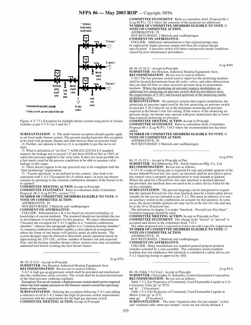
335
NFPA 86 — May 2003 ROP — Copyright, NFPA
Figure A-5-7.3.1 Exception for multiple burner system using proof of closure switches as per 5-7.3.1 (a) 2 and (b) 3
SUBSTANTIATION: 1) The multi-burner exception should equally apply to oil fired multi-burner system. The present standard permits this exception to be used with propane, butane and other heavier than air gaseous fuels. 2) Further, our opinion is that (a) (1) is acceptable to gas but not to oil fuels. 3) What is definition of “no flow”? ANSI Z21.21/CGA 6.5 standard requires the leakage not to exceed 1 ft3 per hour (0.028 m3/hr) at 150% of rated inlet pressure applied to the valve inlet. It does not seem possible for a fuel meter sized for the process conditions to be able to measure valve leakage in this range. 4) There doesn’t appear to be any practical way to be compliant with the “fuel monitoring” requirement. 5) “Unsafe operation” is not defined in this context. Also look to be consistent with 5-4.1.5 Exception (b) (3) which states “at least one burner remains in operating in the common combustion chamber of the burner to be re-ignited”.COMMITTEE MEETING ACTION:Accept in PrincipleCOMMITTEE STATEMENT: Refer to committee draft, Committee Proposal 86-1 (Log # CP1), section 7.7.2.NUMBER OF COMMITTEE MEMBERS ELIGIBLE TO VOTE:31VOTE ON COMMITTEE ACTION: AFFIRMATIVE: 29 NOT RETURNED: 2 Mattiola and vanHeijningenCOMMENT ON AFFIRMATIVE: COLLIER: Substantiation 3 & 4 are based on current technology or knowledge of current methods. The standard should not invalidate the use or development of technologies for this purpose. We reject substantiation 5 because the exception for 5-4.1.5 applies to a “common combustion chamber”, whereas this paragraph applies to a “common heating chamber”. A common combustion chamber implies a close physical arrangement where the flame of one burner will quickly ignite an unlit burner. The system designer must be allowed to determine unsafe operation based on approaching the 25% LEL, airflow, number of burners out and expected flow, and the heating chamber design (where certain areas may accumulate unburned fuel before reaching the next burner flame).
————————————————-
(Log #33)86-35-(5-8.2) : Accept in Principle SUBMITTER: Jim Houston, Industrial Heating Equipment Assn.RECOMMENDATION: Revise text to read as follows: 5-8.2 A high gas or oil pressure switch shall be provided and interlocked into the combustion safety circuitry. The switch shall be located downstream of the final pressure-reducing regulator. Exception: For an oil system, a high pressure switch shall not be required where the fuel supply pressure to the burners cannot exceed the operating limits of the system.SUBSTANTIATION: Deleting the exception following 5-8.2 and adding a reference to oil in 5-8.2 makes the high oil pressure switch requirements consistent with the requirements for the high gas pressure switch.COMMITTEE MEETING ACTION:Accept in Principle
COMMITTEE STATEMENT: Refer to committee draft, Proposal 86-1 (Log #CP1), 7.8.2 where the concerns of the proposal are addressed.NUMBER OF COMMITTEE MEMBERS ELIGIBLE TO VOTE:31VOTE ON COMMITTEE ACTION: AFFIRMATIVE: 29 NOT RETURNED: 2 Mattiola and vanHeijningenCOMMENT ON AFFIRMATIVE: COLLIER: Additional substantiation is that original pumps may be replaced by higher pressure output unit than the original design specification. A pressure switch will detect and prevent unsafe conditions caused by poor maintenance procedures.
————————————————-
(Log #40)86-36-(5-10.2) : Accept in Principle SUBMITTER: Jim Houston, Industrial Heating Equipment Assn.RECOMMENDATION: Revise text to read as follows: 5-10.2 The low pressure switch used to supervise the atomizing medium shall be located downstream from all cocks, valves, and other obstructions that can shut off flow or cause excessive pressure drop of atomization medium. Where the atomizing air pressure requires modulation, an additional low atomizing air pressure switch shall be provided to meet the requirements of 5-10.1 and located upstream of the atomizing media modulating valve. SUBSTANTIATION: On atomizer systems that require modulation, the atomizing air pressure supervised by the low atomizing air pressure switch located per 5-10.2 must be set at the minimum atomizing air pressure required at the burner’s low fire setting. If the source of the atomizing air pressure drops, the burner may operate with poor atomization due to lower than required atomizing air pressure.COMMITTEE MEETING ACTION:Accept in PrincipleCOMMITTEE STATEMENT: Refer to committee draft, Committee Proposal 86-1 (Log #CP1), 7.10.3 where the recommended text has been added.NUMBER OF COMMITTEE MEMBERS ELIGIBLE TO VOTE:31VOTE ON COMMITTEE ACTION: AFFIRMATIVE: 29 NOT RETURNED: 2 Mattiola and vanHeijningen
————————————————-
(Log #76)86-37-(5-15.1) : Accept in Principle in Part SUBMITTER: Ted Jablkowski, P.E., North American Mfg. Co., Ltd.RECOMMENDATION: Revise text as follows: 5-15.1 If a reduced firing rate is required for safe and reliable ignition of the burner (forced Proved low-fire start), an interlock shall be provided to prove the control valve is properly positioned prior to each attempt at ignition. Where the need for a Proved low-fire start interlock is deemed optional but provided, the interlock does not need to be a safety device listed for the service intended. SUBSTANTIATION: The present language can be interpreted to require that the optional Proved low-fire start interlock must be a listed safety device suitable for the service intended as per 5-2.1. The norm in industry is to use an auxiliary switch in the combustion air actuator for this purpose. In some cases, the moist reliable ignition rate may not be at the low fire rate and may be at the 10 or 20 percent rate. The definition in chapter 2 is under “Interlock - Proved Low-Fire Start”. Common language should be used. COMMITTEE MEETING ACTION:Accept in Principle in PartCOMMITTEE STATEMENT: The change from “forced” to “proved” is accepted and shown in the committee draft, 7.15.1. The other proposed text is rejected as it does not add a specific requirement.NUMBER OF COMMITTEE MEMBERS ELIGIBLE TO VOTE:31VOTE ON COMMITTEE ACTION: AFFIRMATIVE: 29 NOT RETURNED: 2 Mattiola and vanHeijningenCOMMENT ON AFFIRMATIVE: COLLIER: Many installations use standard general purpose position switches actuated by a cam assembly. The committee action resultant wording does not emphasize this interlock is considered a safety device per 5-2.1 requiring listing or approval by AHJ.
————————————————-
(Log #12)86-38-(Table 7-5.2.2(a)) : Accept in Principle SUBMITTER: Christopher G. Schaeffer, Control Instrument CorporationRECOMMENDATION: Revise text as follows: Table 7-5.2.2(a) Properties of Commonly Used Flammable Liquids in U.S. Customary Units (ft 3 at 70°F)scf ft 3 [ 9 locations] Table 7-5.2.2(b) Properties of Commonly Used Flammable Liquids in Metric Units m 3 at 21°Cscm m 3 [9 locations] SUBSTANTIATION: The term “standard cubic feet per minute” (scfm) and “standard cubic meter per minute” (scm) are not clearly defined. I
336
NFPA 86 — May 2003 ROP — Copyright, NFPA
have found parties using the terms referenced to different temperatures. It is recommended that the term “standard” be deleted, and the reference temperature be stated as it is in most of NFPA 86. Reference Paragraph A-7-4.1. All volumes and volumetric flow value should indicate temperature and pressure conditions [e.g., 100 ft3/min at 300°F(2.83 m3/min at 148.9°C and ambient pressure] Paragraph A-7.5 “The temperature of the exhaust air also should be measured and the calculated volume the corrected to 70°F (21°C)”. Paragraph 2.1 Definitions, refers to “standard” as a document. National Standards have only standardized the term “Mole”, that is used for derivation of volume measurements. When these terms are used in textbooks they refer to 32°F and 29.92 inches of mercury, also 0°C and 760 mm mercury (1 Standard atmosphere). Where altitude is corrected it should also be stated. Ambient pressure changes due to weather should be ignored.COMMITTEE MEETING ACTION:Accept in PrincipleCOMMITTEE STATEMENT: The committee has added a definition of “standard cubic feet per minute” (scfm) to the draft to address the concerns of the submitter.NUMBER OF COMMITTEE MEMBERS ELIGIBLE TO VOTE:31VOTE ON COMMITTEE ACTION: AFFIRMATIVE: 29 NOT RETURNED: 2 Mattiola and vanHeijningen
————————————————-
(Log #13)86-39-(7-5.2.3) : Accept in Principle SUBMITTER: Christopher G. Schaeffer, Control Instrument CorporationRECOMMENDATION: Revise text as follows: 7-5.2.3* Method for Calculating Solvent Safety Ventilation Rate. U.S. Customary Units at 70° F: The volume of fresh air required for safety ventilation is obtained by multiplying the factor calculated above by the gallons per minute of solvent evaporated in the oven. The resultant value is expressed as standard cubic feet per minute (scfm) (ft3/min) of ventilation at 70° F. This value is to be corrected for the temperature of the exhaust stream exiting the oven enclosure as well as for altitude. with the result being actual cubic feet per minute. (acfm). SI Units at 21° C: The volume of fresh air required for safety ventilation is obtained by multiplying the factor calculated above by the liters per minute of solvent evaporated in the oven. The resultant value is expressed as standard cubic meters per minute (standard m3/min) of ventilation. This value is to be corrected for the temperature of the exhaust stream exiting the oven enclosure as well as for altitude, with the result being actual cubic meters per minute (actual m3/min). SUBSTANTIATION: The term “standard cubic feet per minute” (scfm) and “standard cubic meter per minute” (scm) are not clearly defined. I have found parties using the terms referenced to different temperatures. It is recommended that the term “standard” be deleted, and the reference temperature be stated as it is in most of NFPA 86. Reference Paragraph A-7-4.1. All volumes and volumetric flow value should indicate temperature and pressure conditions [e.g., 100 ft3/min at 300°F(2.83 m3/min at 148.9°C and ambient pressure] Paragraph A-7.5 “The temperature of the exhaust air also should be measured and the calculated volume the corrected to 70°F (21°C)”. Paragraph 2.1 Definitions, refers to “standard” as a document. National Standards have only standardized the term “Mole”, that is used for derivation of volume measurements. When these terms are used in textbooks they refer to 32°F and 29.92 inches of mercury, also 0°C and 760 mm mercury (1 Standard atmosphere). Where altitude is corrected it should also be stated. Ambient pressure changes due to weather should be ignored.COMMITTEE MEETING ACTION:Accept in PrincipleCOMMITTEE STATEMENT: Refer to Committee Action on Proposal 86-38 (Log # 12).NUMBER OF COMMITTEE MEMBERS ELIGIBLE TO VOTE:31VOTE ON COMMITTEE ACTION: AFFIRMATIVE: 29 NOT RETURNED: 2 Mattiola and vanHeijningen
————————————————-
(Log #14)86-40-(7-5.3) : Accept in Principle SUBMITTER: Christopher G. Schaeffer, Control Instrument CorporationRECOMMENDATION: Revise text as follows: 7-5.3 Method for Calculating Ventilation Rate for Products of Combustion.In continuous process ovens, including powder coating ovens, where a direct-fired combustion system (within or remote from the oven chamber) is used, the minimum oven exhaust volume for safety ventilation shall include the volume of combustion products from burners. The value used for the products of combustion shall be 183 cfm ft3/min at 70°F scfm (5.18 standard m3/min at 21°C) per 1,000,000 Btu/hr (293.1 kW) burner rating. The products of combustion shall be adjusted for oven operating temperature and altitude. This value shall be added credited to the ventilation value determined from 7-5.2. SUBSTANTIATION: The term “standard cubic feet per minute” (scfm) and “standard cubic meter per minute” (scm) are not clearly defined. I have found parties using the terms referenced to different temperatures.
It is recommended that the term “standard” be deleted, and the reference temperature be stated as it is in most of NFPA 86. Reference Paragraph A-7-4.1. All volumes and volumetric flow value should indicate temperature and pressure conditions [e.g., 100 ft3/min at 300°F(2.83 m3/min at 148.9°C and ambient pressure] Paragraph A-7.5 “The temperature of the exhaust air also should be measured and the calculated volume the corrected to 70°F (21°C)”. Paragraph 2.1 Definitions, refers to “standard” as a document. National Standards have only standardized the term “Mole”, that is used for derivation of volume measurements. When these terms are used in textbooks they refer to 32°F and 29.92 inches of mercury, also 0°C and 760 mm mercury (1 Standard atmosphere). Where altitude is corrected it should also be stated. Ambient pressure changes due to weather should be ignored.COMMITTEE MEETING ACTION:Accept in PrincipleCOMMITTEE STATEMENT: Refer to Committee Action on Proposal 86-38 (Log # 12).NUMBER OF COMMITTEE MEMBERS ELIGIBLE TO VOTE:31VOTE ON COMMITTEE ACTION: AFFIRMATIVE: 29 NOT RETURNED: 2 Mattiola and vanHeijningen
————————————————-
(Log #15)86-41-(7-6.2) : Accept in Principle SUBMITTER: Christopher G. Schaeffer, Control Instrument CorporationRECOMMENDATION: Revise text as follows: 7-6.2* Method for Estimating Rate of Ventilation. In batch ovens, the safety ventilation rate shall be designed and maintained to provide at least 440 scfm ft3/min at 70°F of air per gal (3.29 standard m3/min at 21°C of air per L) of flammable volatiles in each batch. SUBSTANTIATION: The term “standard cubic feet per minute” (scfm) and “standard cubic meter per minute” (scm) are not clearly defined. I have found parties using the terms referenced to different temperatures. It is recommended that the term “standard” be deleted, and the reference temperature be stated as it is in most of NFPA 86. Reference Paragraph A-7-4.1. All volumes and volumetric flow value should indicate temperature and pressure conditions [e.g., 100 ft3/min at 300°F(2.83 m3/min at 148.9°C and ambient pressure] Paragraph A-7.5 “The temperature of the exhaust air also should be measured and the calculated volume the corrected to 70°F (21°C)”. Paragraph 2.1 Definitions, refers to “standard” as a document. National Standards have only standardized the term “Mole”, that is used for derivation of volume measurements. When these terms are used in textbooks they refer to 32°F and 29.92 inches of mercury, also 0°C and 760 mm mercury (1 Standard atmosphere). Where altitude is corrected it should also be stated. Ambient pressure changes due to weather should be ignored.COMMITTEE MEETING ACTION:Accept in PrincipleCOMMITTEE STATEMENT: Refer to Committee Action on Proposal 86-38 (Log # 12).NUMBER OF COMMITTEE MEMBERS ELIGIBLE TO VOTE:31VOTE ON COMMITTEE ACTION: AFFIRMATIVE: 29 NOT RETURNED: 2 Mattiola and vanHeijningen
————————————————-
(Log #16)86-42-(7-6.3) : Accept in Principle SUBMITTER: Christopher G. Schaeffer, Control Instrument CorporationRECOMMENDATION: Revise text as follows: 7-6.3 Method for Calculating Ventilation Rate. The 440 scfm ft3/min of 70°F air per gal (3.29 standard m3/min of 21°C air per L) of solvent shall be used unless the maximum…………….. Exception No. 2: The safety ventilation shall be permitted to be calculated by determining the amount of ventilation air in scf ft3 at 70°F (standard m3 at 21°C) that is rendered barely flammable by the vapor generated in gal per hour (L per hour) of solvent in use. This value shall then be multiplied by an empirical factor of 10 and divided by 60 min/hour to obtain the safety ventilation in scfm ft3/min at 70°F (standard m3/min at 21°C). SUBSTANTIATION: The term “standard cubic feet per minute” (scfm) and “standard cubic meter per minute” (scm) are not clearly defined. I have found parties using the terms referenced to different temperatures. It is recommended that the term “standard” be deleted, and the reference temperature be stated as it is in most of NFPA 86. Reference Paragraph A-7-4.1. All volumes and volumetric flow value should indicate temperature and pressure conditions [e.g., 100 ft3/min at 300°F(2.83 m3/min at 148.9°C and ambient pressure] Paragraph A-7.5 “The temperature of the exhaust air also should be measured and the calculated volume the corrected to 70°F (21°C)”. Paragraph 2.1 Definitions, refers to “standard” as a document. National Standards have only standardized the term “Mole”, that is used for derivation of volume measurements. When these terms are used in textbooks they refer to 32°F and 29.92 inches of mercury, also 0°C and 760 mm mercury (1 Standard atmosphere). Where altitude is corrected it should also be stated. Ambient pressure changes due to weather should be ignored.COMMITTEE MEETING ACTION:Accept in PrincipleCOMMITTEE STATEMENT: Refer to Committee Action on Proposal 86-38 (Log # 12).
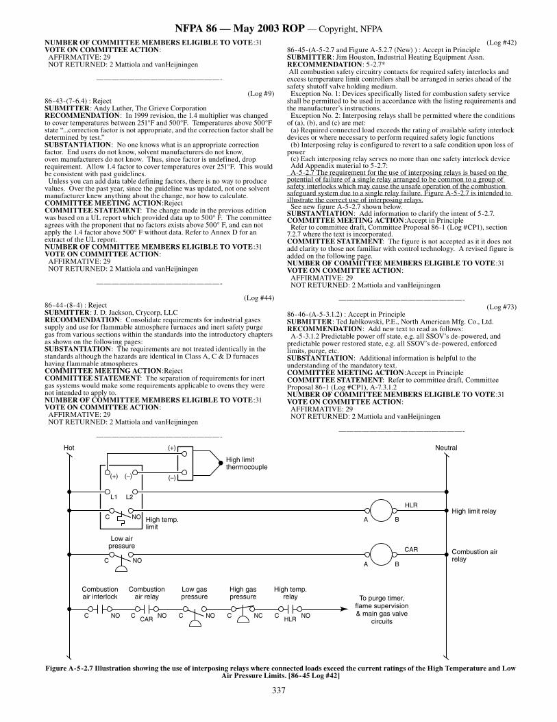
337
NFPA 86 — May 2003 ROP — Copyright, NFPA
NUMBER OF COMMITTEE MEMBERS ELIGIBLE TO VOTE:31VOTE ON COMMITTEE ACTION: AFFIRMATIVE: 29 NOT RETURNED: 2 Mattiola and vanHeijningen
————————————————-
(Log #9)86-43-(7-6.4) : Reject SUBMITTER: Andy Luther, The Grieve CorporationRECOMMENDATION: In 1999 revision, the 1.4 multiplier was changed to cover temperatures between 251°F and 500°F. Temperatures above 500°F state “...correction factor is not appropriate, and the correction factor shall be determined by test.” SUBSTANTIATION: No one knows what is an appropriate correction factor. End users do not know, solvent manufacturers do not know, oven manufacturers do not know. Thus, since factor is undefined, drop requirement. Allow 1.4 factor to cover temperatures over 251°F. This would be consistent with past guidelines. Unless you can add data table defining factors, there is no way to produce values. Over the past year, since the guideline was updated, not one solvent manufacturer knew anything about the change, nor how to calculate.COMMITTEE MEETING ACTION:RejectCOMMITTEE STATEMENT: The change made in the previous edition was based on a UL report which provided data up to 500° F. The committee agrees with the proponent that no factors exists above 500° F, and can not apply the 1.4 factor above 500° F without data. Refer to Annex D for an extract of the UL report. NUMBER OF COMMITTEE MEMBERS ELIGIBLE TO VOTE:31VOTE ON COMMITTEE ACTION: AFFIRMATIVE: 29 NOT RETURNED: 2 Mattiola and vanHeijningen
————————————————-
(Log #44)86-44-(8-4) : Reject SUBMITTER: J. D. Jackson, Crycorp, LLCRECOMMENDATION: Consolidate requirements for industrial gases supply and use for flammable atmosphere furnaces and inert safety purge gas from various sections within the standards into the introductory chapters as shown on the following pages:SUBSTANTIATION: The requirements are not treated identically in the standards although the hazards are identical in Class A, C & D furnaces having flammable atmospheresCOMMITTEE MEETING ACTION:RejectCOMMITTEE STATEMENT: The separation of requirements for inert gas systems would make some requirements applicable to ovens they were not intended to apply to. NUMBER OF COMMITTEE MEMBERS ELIGIBLE TO VOTE:31VOTE ON COMMITTEE ACTION: AFFIRMATIVE: 29 NOT RETURNED: 2 Mattiola and vanHeijningen
————————————————-
(Log #42)86-45-(A-5-2.7 and Figure A-5.2.7 (New) ) : Accept in Principle SUBMITTER: Jim Houston, Industrial Heating Equipment Assn.RECOMMENDATION: 5-2.7* All combustion safety circuitry contacts for required safety interlocks and excess temperature limit controllers shall be arranged in series ahead of the safety shutoff valve holding medium. Exception No. 1: Devices specifically listed for combustion safety service shall be permitted to be used in accordance with the listing requirements and the manufacturer’s instructions. Exception No. 2: Interposing relays shall be permitted where the conditions of (a), (b), and (c) are met: (a) Required connected load exceeds the rating of available safety interlock devices or where necessary to perform required safety logic functions (b) Interposing relay is configured to revert to a safe condition upon loss of power (c) Each interposing relay serves no more than one safety interlock device Add Appendix material to 5-2.7: A-5-2.7 The requirement for the use of interposing relays is based on the potential of failure of a single relay arranged to be common to a group of safety interlocks which may cause the unsafe operation of the combustion safeguard system due to a single relay failure. Figure A-5-2.7 is intended to illustrate the correct use of interposing relays. See new figure A-5-2.7 shown below.SUBSTANTIATION: Add information to clarify the intent of 5-2.7.COMMITTEE MEETING ACTION:Accept in Principle Refer to committee draft, Committee Proposal 86-1 (Log #CP1), section 7.2.7 where the text is incorporated.COMMITTEE STATEMENT: The figure is not accepted as it it does not add clarity to those not familiar with control technology. A revised figure is added on the following page.NUMBER OF COMMITTEE MEMBERS ELIGIBLE TO VOTE:31VOTE ON COMMITTEE ACTION: AFFIRMATIVE: 29 NOT RETURNED: 2 Mattiola and vanHeijningen
————————————————-(Log #73)
86-46-(A-5-3.1.2) : Accept in Principle SUBMITTER: Ted Jablkowski, P.E., North American Mfg. Co., Ltd.RECOMMENDATION: Add new text to read as follows: A-5-3.1.2 Predictable power off state, e.g. all SSOV’s de-powered, and predictable power restored state, e.g. all SSOV’s de-powered, enforced limits, purge, etc. SUBSTANTIATION: Additional information is helpful to the understanding of the mandatory text. COMMITTEE MEETING ACTION:Accept in PrincipleCOMMITTEE STATEMENT: Refer to committee draft, Committee Proposal 86-1 (Log #CP1), A-7.3.1.2NUMBER OF COMMITTEE MEMBERS ELIGIBLE TO VOTE:31VOTE ON COMMITTEE ACTION: AFFIRMATIVE: 29 NOT RETURNED: 2 Mattiola and vanHeijningen
————————————————-
�������������������
����������������
�����������������
���������������� ���������������
�����������������������������������
��������
�����������������������
��� ����������
��� ������
�� ��
�� �����������������
����������������������
���������������
�
���
���
� �
���
�������������������
�������������������
� �
������ ��� ��� ������
Figure A-5-2.7 Illustration showing the use of interposing relays where connected loads exceed the current ratings of the High Temperature and Low Air Pressure Limits. [86-45 Log #42]
338
NFPA 86 — May 2003 ROP — Copyright, NFPA
NFPA 86C NFPA 86 NFPA 86D PROPOSED COMBINED INTRO. CHAPTERS
7-5 Bulk Storage and Generated Supply Systems for Special Atmospheres.
8-4 Inert Gas Generation and Storage Systems
Inert Gas Generation and Storage Systems
7-5.1 General General. This section shall apply to Class A ovens and Class C and Class D furnaces that have a flammable atmosphere.
8-4.1 The oven system shall have an inert gas supply for oxygen control and purging. Inert gas for reduction and control of oxygen within the oven enclosure and associated equipment shall be any of the following types: (1) Inert gas generators that burn a combustible gas stoichiometrically to produce an inert gas after removal of water vapor (2) Pressure swing adsorption producing nitrogen (3) Nitrogen produced by membrane separation equipment (4) Nitrogen, carbon dioxide, or other inert gases, produced in liquid form. Such liquefied gases are transported to the site and stored in a liquid storage tank (see section 8-5).
The oven system shall have an inert gas supply for oxygen control and purging. Inert gas for reduction and control of oxygen within the oven enclosure and associated equipment shall be any of the following types: (1) Inert gas generators that burn a combustible gas stoichiometrically to produce an inert gas after removal of water vapor (2) Pressure swing adsorption producing nitrogen (3) Nitrogen produced by membrane separation equipment (4) Nitrogen, carbon dioxide, or other inert gases, produced in liquid form. Such liquefied gases are transported to the site and stored in a liquid storage tank (see section 8-5).
7-5.1.1 All storage tanks and cylinders shall comply with local, state, and federal codes relating to the types of fluids stored, their pressures, and their temperatures. The applicable NFPA standards shall be followed.
8-4.2 All storage tanks and compressed gas cylinders shall comply with local, state, and federal codes relating to the types of fluids stored, their pressures, and their temperatures. The applicable NFPA standards shall be followed.
8-1.1 All storage tanks and cylinders shall comply with local, state, and federal codes relating to pressures and type of gas. NFPA standards shall also be followed.
All storage tanks and compressed gas cylinders shall comply with local, state, and federal codes relating to the types of fluids stored, their pressures, and their temperatures. The applicable NFPA standards shall be followed.
8-4.3 Vessels, controls and piping that maintain their integrity at the maximum/minimum design pressures and temperatures shall be provided.
8-1.2 Vessels, controls, and piping shall be constructed to maintain their integrity under maximum design pressures and temperatures.
Vessels, controls and piping that maintain their integrity at the maximum/minimum design pressures and temperatures shall be provided.
7-5.1.2 Piping and piping components shall be in accordance with ASME B31.3, Process Piping.
Piping and piping components shall be in accordance with ASME B31.3, Process Piping.
7-5.1.3 When an ASME tank is used, the tank relief devices provided shall be sized, constructed, and tested in accordance with the ASME Boiler and Pressure Vessel Code, Section VIII, Division 1.
8-4.4 ASME tank relief devices shall be provided and sized, constructed, and tested in accordance with ASME Boiler and Pressure Vessel Code, Section VIII, Division 1.
When an ASME tank is used, the tank relief devices provided shall be sized, constructed, and tested in accordance with the ASME Boiler and Pressure Vessel Code, Section VIII, Division 1.
7-5.1.4 Locations for tanks and cylinders containing flammable or toxic fluids shall comply with the applicable NFPA standards.
8-4.5 Locations for compressed gas tanks and cylinders shall be selected with adequate consideration given to exposure to buildings, processes, personnel, and other storage facilities. Tables of distances specified in the various NFPA standards shall be followed.
8-2 Locations for tanks and cylinders containing flammable or toxic gases shall be selected with adequate consideration given to exposure to buildings, processes, storage facilities, and personnel. Tables of distances specified in the various NFPA standards shall be followed.
Locations for tanks and cylinders containing flammable or toxic fluids shall comply with the applicable NFPA standards.
8-6.5 The pressure of the inert gas system shall be regulated to avoid overpressurizing components in the system such as glass tube flowmeters.
The pressure of the inert gas system shall be regulated to avoid overpressurizing components in the system such as glass tube flowmeters.
8-7 Inert Gas Piping System Inert Gas Piping System
339
NFPA 86 — May 2003 ROP — Copyright, NFPA
NFPA 86C NFPA 86 NFPA 86D PROPOSED COMBINED INTRO. CHAPTERS
7-5.1.6 A supply of inert purge gas of known and acceptable analysis shall be available where required by this standard. The processing of inert gas shall not deplete the adequacy of the inert purge gas supply. The inert purge gas contains flammable constituent gases, their combined concentration in the purge gas mixture shall be less than 25% of the lower flammable limit (LFL). Mixed inert purge gases shall be analyzed on a continuous basis to ensure that the oxygen and combustible gas concentrations remain within the limits specified in this paragraph. Exception: Continuous analysis shall not be required if the inert purge gas is stored.
A supply of inert purge gas of known and acceptable analysis shall be available where required by this standard. The processing of inert gas shall not deplete the adequacy of the inert purge gas supply. The inert purge gas contains flammable constituent gases, their combined concentration in the purge gas mixture shall be less than 25% of the lower flammable limit (LFL). Mixed inert purge gases shall be analyzed on a continuous basis to ensure that the oxygen and combustible gas concentrations remain within the limits specified in this paragraph. Exception: Continuous analysis shall not be required if the inert purge gas is stored.
7-5.1.7 Bulk storage systems shall be rated and installed to provide adequate and reliable flow of special atmospheres to the user equipment if an interruption of the flow can create an explosion hazard.
8-4.6 Bulk storage systems shall be rated and installed to ensure reliable and uninterrupted flow of inert gas to the user equipment as necessary.
Bulk storage systems shall be rated and installed to ensure reliable and uninterrupted flow of inert gas to the user equipment as necessary.
7-5.1.8 In the case of inert gases that might be used as safety purge media, the volume stored always shall be sufficient to purge all connected special atmosphere furnaces with at least five furnace volume changes wherever the flammable atmospheres are being used.
8-4.7 Where inert gases are used as safety purge media, the volume stored always shall be sufficient to purge all connected low-oxygen atmosphere furnaces with at least five oven volumes (see 8-5.1). Recirculating fans shall be kept operating during the purge. Exception: The stored volume shall be permitted to be reduced, provided both of the following conditions are met: (a) Mixing is adequate (b) The stored volume is sufficient to reduce the concentration in the oven to the LEL in air.
Where inert gases are used as safety purge media, the volume stored always shall be sufficient to purge all connected low-oxygen atmosphere and special atmosphere furnaces with at least five oven volumes (see 8-5.1).
Recirculating fans on low-atmosphere furnaces shall be kept operating during the purge. Exception: The stored volume shall be permitted to be reduced, provided both of the following conditions are met: (a) Mixing is adequate (b) The stored volume is sufficient to reduce the concentration in the oven to less than 50% of the LEL in air.
7-5.2 Vaporizers Used for Safety Purging.
8-5 Vaporizers Used for Liquefied Purging Fluids.
Vaporizers Used for Safety Purging.
340
NFPA 86 — May 2003 ROP — Copyright, NFPA
NFPA 86C NFPA 86 NFPA 86D PROPOSED COMBINED INTRO. CHAPTERS
7-5.2.1 Vaporizers utilized to convert cryogenic liquids to the gas state shall be ambient air heat transfer units so that flow from such vaporizers is unaffected by the loss of power. Exception: Use of powered vaporizers shall be permitted, provided that one of the following conditions is satisfied. (a) The vaporizer has reserve heating capacity sufficient to continue vaporizing at least five furnace volumes at the required purge flow rate immediately following power interruption. (b) Reserve ambient vaporizers are provided that are piped to the source of supply so that they are unaffected by a freeze-up or flow stoppage of gas from the powered vaporizer. The reserve vaporizers shall be capable of evaportating at leastr five furnace fvolumes at the required purge flow rate. (c) Purge gas is available from an alternate source that is capable of supplying five volume changes after interruption of the flow of the atmosphere gas to the furnace.
8-5.1 Vaporizers utilized to convert cryogenic fluids to the gas state shall be ambient air-heated units so that their flow is unaffected by a loss of power. Exception: Use of powered vaporizers shall be permitted, provided one of the following conditions is met: (a) The vaporizer has reserve heating capacity sufficient to continue vaporizing at least five oven volumes at the required purge flow rate immediately following power interruption. (b) Reserve ambient vaporizers are provided taht are piped to the source of supply so as to be unaffected by a freeze-up or flow stoppage of gas from the power vaporizer. The reserve vaporizer sahll be capable of evaporating at least five oven volumes at the required purge flow rate. (c) Purge gas is available from an alternate sourch that fulfills the requirements of 8-4.6, 8-4.7, 8-5.2, and 8-5.4.
Vaporizers utilized to convert cryogenic fluids to the gas state shall be ambient air-heated units so that their flow is unaffected by a loss of power. Exception: Use of powered vaporizers shall be permitted, provided one of the following conditions is met: (a) The vaporizer has reserve heating capacity sufficient to continue vaporizing at least five oven volumes at the required purge flow rate immediately following power interruption. (b) Reserve ambient vaporizers are provided that are piped to the source of supply so as to be unaffected by a freeze-up or flow stoppage of gas from the power vaporizer. The reserve vaporizer sahll be capable of evaporating at least five oven volumes at the required purge flow rate. (c) Purge gas is available from an alternate sourch that fulfills the requirements of 8-4.6, 8-4.7, 8-5.2, and 8-5.4.
7-5.2.2 Vaporizers shall be rated by the industrial gas supplier or the owner to vaporize at 150% of the highest purge gas demand for all connected equipment. Winter temperature extremes for the locale shall be taken into consideration by the agency responsible for rating the vaporizers.
8-5.2 Vaporizers shall be rated by the industrial gas supplier or the owner to vaporize at 150% of the highest purge gas demand for all connected equipment. Winter temperature extremes for the locale shall be taken into consideration by the agency responsible for rating them.
Vaporizers shall be rated by the industrial gas supplier or the owner to vaporize at 150% of the highest purge gas demand for all connected equipment. Winter temperature extremes for the locale shall be taken into consideration by the agency responsible for rating them.
7-5.2.3 It shall be the user’s responsibility to inform the industrial gas supplier of additions to the plant that materially increase the inert gas consumption rate so that vaporizer and storage capacity can be resized for the revised requirements.
8-5.3 It shall be the user’s responsibility to inform the industrial gas supplier of additions to the plant that materially increase the inert gas consumption rate so that vaporizer and storage capacity can be resized for the revised requirements.
It shall be the user’s responsibility to inform the industrial gas supplier of additions to the plant that materially increase the inert gas consumption rate so that vaporizer and storage capacity can be resized for the revised requirements.
8-5.4* The vaporizer shall be protected against flow demands that exceed its rate of rapacity when this can cause closure of a low-temperature shutoff valve.
The vaporizer shall be protected against flow demands that exceed its rate of rapacity when this can cause closure of a low-temperature shutoff valve.
8-5.5 A temperature indicator shall be installed in the vaporizer effluent piping. An audible or visual low-temperature alarm shall be provided to alert oven operators whenever the temperature is in danger of reaching the set point of the low-temperature flow shutoff valve, so they can begin corrective actions in advance of the flow stoppage.
A temperature indicator shall be installed in the vaporizer effluent piping. An audible or visual low-temperature alarm shall be provided to alert oven operators whenever the temperature is in danger of reaching the set point of the low-temperature flow shutoff valve, so they can begin corrective actions in advance of the flow stoppage.
7-5.2.5* A device shall be installed that prevents the flow rate of gas from exceeding the vaporizer capacity and thereby threatening the integrity of downstream equipment or control devices due to exposure to cryogenic fluids.
A device shall be installed that prevents the flow rate of gas from exceeding the vaporizer capacity and thereby threatening the integrity of downstream equipment or control devices due to exposure to cryogenic fluids.
7-5.3 Storage Systems. Storage Systems.
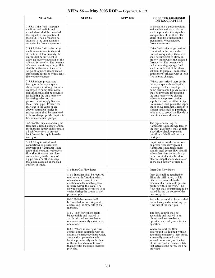
341
NFPA 86 — May 2003 ROP — Copyright, NFPA
NFPA 86C NFPA 86 NFPA 86D PROPOSED COMBINED INTRO. CHAPTERS
7-5.3.1 If the fluid is a purge medium, and audible and visual alarm shall be provided that signals a low quantity of the fluid. The alarm shall be situated in the area normally occupied by furnace operators.
If the fluid is a purge medium, and audible and visual alarm shall be provided that signals a low quantity of the fluid. The alarm shall be situated in the area normally occupied by furnace operators.
7-5.3.2 If the fluid is the purge medium contained in the tank at the time of low quantity, the alarm shall be sufficient to allow an orderly shutdown of the affected furnace’s). The contents of a tank containing a purge fluid shall be sufficient at the alarm set point to purge all connected atmosphere furnaces with at least five volume changes.
If the fluid is the purge medium contained in the tank at the time of low quantity, the alarm shall be sufficient to allow an orderly shutdown of the affected furnace(s). The contents of a tank containing a purge fluid shall be sufficient at the alarm set point to purge all connected atmosphere furnaces with at least five volume changes.
7-5.3.3 Where pressurized inert gas in the vapor space above liquids in storage tanks is employed to pump flammable liquids, means shall be provided for isolating the tank remotely by closing valves on the pressurization supply line and the effluent pipe. Pressurized inert gas in the vapor space above flammable liquids in storage tanks shall be permitted to be used to propel the liquids in lieu of mechanical pumps.
Where pressurized inert gas in the vapor space above liquids in storage tanks is employed to pump flammable liquids, means shall be provided for isolating the tank remotely by closing valves on the pressurization supply line and the effluent pipe. Pressurized inert gas in the vapor space above flammable liquids in storage tanks shall be permitted to be used to propel the liquids in lieu of mechanical pumps.
7-5.3.4 The pipe connecting the flammable liquid storage tank to the inert gas supply shall contain a backflow check to prevent backflow of the liquid into the inert gas.
The pipe connecting the flammable liquid storage tank to the inert gas supply shall contain a backflow check to prevent backflow of the liquid into the inert gas.
7-5.3.5 Liquid withdrawal connections on pressurized aboveground flammable liquid tanks shall contain steel excess flow shutoff valves that close automatically in the event of a pipe break or other mishap that could cause an unchecked outflow of liquid.
Liquid withdrawal connections on pressurized aboveground flammable liquid tanks shall contain steel excess flow shutoff valves that close automatically in the event of a pipe break or other mishap that could cause an unchecked outflow of liquid.
8-6 Inert Gas Flow Rates Inert Gas Flow Rates
8-6.1 Inert gas shall be required to dilute air infiltration, which otherwise can result in the creation of a flammable gas-air mixture within the oven. The flow rate shall be permitted to be varied during the course of the process cycle.
Inert gas shall be required to dilute air infiltration, which otherwise can result in the creation of a flammable gas-air mixture within the oven. The flow rate shall be permitted to be varied during the course of the process cycle.
8-6.2 Reliable means shall be provided for metering and controlling the flow rate of the inert gas.
Reliable means shall be provided for metering and controlling the flow rate of the inert gas.
8-6.3 The flow control shall be accessible and located in an illuminated area so that an operator can readily monitor its operation.
The flow control shall be accessible and located in an illuminated area so that an operator can readily monitor its operation.
8-6.4 Where an inert gas flow control unit is equipped with an automatic emergency inert purge, a manually operated switch located prominently on the face of the unit, and a remote switch that activates the purge, shall be provided.
Where an inert gas flow control unit is equipped with an automatic emergency inert purge, a manually operated switch located prominently on the face of the unit, and a remote switch that activates the purge, shall be provided.
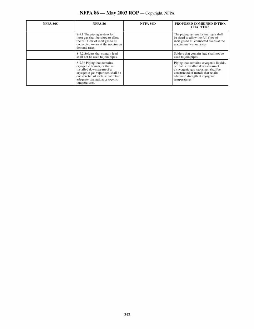
342
NFPA 86 — May 2003 ROP — Copyright, NFPA
NFPA 86C NFPA 86 NFPA 86D PROPOSED COMBINED INTRO. CHAPTERS
8-7.1 The piping system for inert gas shall be sized to allow the full flow of inert gas to all connected ovens at the maximum demand rates.
The piping system for inert gas shall be sized to allow the full flow of inert gas to all connected ovens at the maximum demand rates.
8-7.2 Solders that contain lead shall not be used to join pipes.
Solders that contain lead shall not be used to join pipes.
8-7.3* Piping that contains cryogenic liquids, or that is installed downstream of a cryogenic gas vaporizer, shall be constructed of metals that retain adequate strength at cryogenic temperatures.
Piping that contains cryogenic liquids, or that is installed downstream of a cryogenic gas vaporizer, shall be constructed of metals that retain adequate strength at cryogenic temperatures.
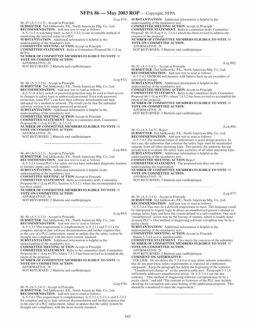
343
NFPA 86 — May 2003 ROP — Copyright, NFPA
(Log #74)86-47-(A-5-3.1.5) : Accept in Principle SUBMITTER: Ted Jablkowski, P.E., North American Mfg. Co., Ltd.RECOMMENDATION: Add new text to read as follows: A-5-3.1.5 A watchdog timer, as per 5-3.3.2, is one acceptable method of monitoring the internal status of a PLC. SUBSTANTIATION: Additional information is helpful in the understanding of the mandatory text.COMMITTEE MEETING ACTION:Accept in PrincipleCOMMITTEE STATEMENT: Refer to Committee Proposal 86-1 (Log #CP1).NUMBER OF COMMITTEE MEMBERS ELIGIBLE TO VOTE:31VOTE ON COMMITTEE ACTION: AFFIRMATIVE: 29 NOT RETURNED: 2 Mattiola and vanHeijningen
————————————————-
(Log #72)86-48-(A-5-3.1.6) : Accept in Principle SUBMITTER: Ted Jablkowski, P.E., North American Mfg. Co., Ltd.RECOMMENDATION: Add new text to read as follows: A-5-3.1.6 A key switch or password protection may be used to limit access to changes to safety logic to authorized personnel. Even with password protection, some PLC’s can have their software downloaded and then uploaded via a modem or network. The result can be that the uploaded software version is no longer password protected. SUBSTANTIATION: Additional information is helpful in the understanding of the mandatory text.COMMITTEE MEETING ACTION:Accept in PrincipleCOMMITTEE STATEMENT: Refer to committee draft, Committee Proposal 86-1 (Log # CP1), A-7.3.1.6NUMBER OF COMMITTEE MEMBERS ELIGIBLE TO VOTE:31VOTE ON COMMITTEE ACTION: AFFIRMATIVE: 29 NOT RETURNED: 2 Mattiola and vanHeijningen
————————————————-
(Log #84)86-49-(A-5-3.2.1) : Accept in Principle SUBMITTER: Ted Jablkowski, P.E., North American Mfg. Co., Ltd.RECOMMENDATION: Add new text to read as follows: A-5-3.2.1 Listed PLC’s for safety service have embedded diagnostic features to monitor inputs and verify outputs. SUBSTANTIATION: Additional information is helpful in the understanding of the mandatory text.COMMITTEE MEETING ACTION:Accept in PrincipleCOMMITTEE STATEMENT: Refer to committee draft, Committee Proposal 86-1 (Log #CP1), Section A.5.3.2.1 where the recommended text has been added.NUMBER OF COMMITTEE MEMBERS ELIGIBLE TO VOTE:31VOTE ON COMMITTEE ACTION: AFFIRMATIVE: 29 NOT RETURNED: 2 Mattiola and vanHeijningen
————————————————-
(Log #83)86-50-(A-5-3.3.3) : Accept in Principle SUBMITTER: Ted Jablkowski, P.E., North American Mfg. Co., Ltd.RECOMMENDATION: Add new text to read as follows: A-5-3.3.3 This requirement is complementary to 5-3.1.1 and 5-3.1.4 for complete and up to date software documentation and further requires that in the case of a PLC replacement, repair or update that the safety system be brought into compliance with the most current standard. SUBSTANTIATION: Additional information is helpful in the understanding of the mandatory text. COMMITTEE MEETING ACTION:Accept in PrincipleCOMMITTEE STATEMENT: Refer to the committee draft, Committee Proposal 86-1 (Log # CP1), where 7.3.3.3 has been revised to acomplish the intent of the proposal.NUMBER OF COMMITTEE MEMBERS ELIGIBLE TO VOTE:31VOTE ON COMMITTEE ACTION: AFFIRMATIVE: 29 NOT RETURNED: 2 Mattiola and vanHeijningen
————————————————-
(Log #78)86-51-(A-5-3.4.1) : Accept in Principle SUBMITTER: Ted Jablkowski, P.E., North American Mfg. Co., Ltd.RECOMMENDATION: Add new text to read as follows: A-5-3.4.1 This requirement is complementary to 5-3.1.1, 5-3.1.4, and 5-3.3.3 for complete and up to date software documentation and further requires that in the case of a PLC replacement, repair or update that the safety system be brought into compliance with the most current standard.
SUBSTANTIATION: Additional information is helpful in the understanding of the mandatory text. COMMITTEE MEETING ACTION:Accept in PrincipleCOMMITTEE STATEMENT: Refer to committee draft, Committee Proposal 86-10 (Log # 1), 7.3.4.1 which has been revised to address the concern of the proposal.NUMBER OF COMMITTEE MEMBERS ELIGIBLE TO VOTE:31VOTE ON COMMITTEE ACTION: AFFIRMATIVE: 29 NOT RETURNED: 2 Mattiola and vanHeijningen
————————————————-
(Log #82)86-52-(A-5-3.4.2) : Accept in Principle SUBMITTER: Ted Jablkowski, P.E., North American Mfg. Co., Ltd.RECOMMENDATION: Add new text to read as follows: A-5-3.4.2 EEPROM and memory with battery back up are examples of nonvolatile storage. SUBSTANTIATION: Additional information is helpful in the understanding of the mandatory text.COMMITTEE MEETING ACTION:Accept in PrincipleCOMMITTEE STATEMENT: Refer to the committee draft, Committee Proposal 86-1 (Log # CP1), where 7.4.3.2 has been revised to accomplish the intent of the proposal.NUMBER OF COMMITTEE MEMBERS ELIGIBLE TO VOTE:31VOTE ON COMMITTEE ACTION: AFFIRMATIVE: 29 NOT RETURNED: 2 Mattiola and vanHeijningen
————————————————-
(Log #81)86-53-(A-5-3.4.3) : Reject SUBMITTER: Ted Jablkowski, P.E., North American Mfg. Co., Ltd.RECOMMENDATION: Add new text to read as follows: A-5-3.4.3 The modularization of subroutines is good design practice. In this case, the subroutine that contains the safety logic must be maintained separate from all other operating logic. This permits the authority having jurisdiction to evaluate the safety logic exclusive of all other operating logic. SUBSTANTIATION: Additional information is helpful in the understanding of the mandatory text.COMMITTEE MEETING ACTION:RejectCOMMITTEE STATEMENT: The proposed text does not aid in understanding the requirement.NUMBER OF COMMITTEE MEMBERS ELIGIBLE TO VOTE:31VOTE ON COMMITTEE ACTION: AFFIRMATIVE: 29 NOT RETURNED: 2 Mattiola and vanHeijningen
————————————————-
(Log #77)86-54-(A-5-3.4.4) : Accept in Principle SUBMITTER: Ted Jablkowski, P.E., North American Mfg. Co., Ltd.RECOMMENDATION: Add new text to read as follows: A-5-3.4.4 This may be a difficult requirement to meet. This language could be interpreted to require logic to detect an unauthorized person’s attempt to change safety logic and have the system default to a safe condition. One such “unauthorized” action may be the forcing of outputs, which is readily done in many PLC’s. One method of diagnosing software corruption may be by a parity check. SUBSTANTIATION: Additional information is helpful in the understanding of the mandatory text. COMMITTEE MEETING ACTION:Accept in Principle Delete 5-3.4.4 as it is unenforceable. COMMITTEE STATEMENT: This meets the concerns of the submitter.NUMBER OF COMMITTEE MEMBERS ELIGIBLE TO VOTE:31VOTE ON COMMITTEE ACTION: AFFIRMATIVE: 29 NOT RETURNED: 2 Mattiola and vanHeijningenCOMMENT ON AFFIRMATIVE: COLLIER: Do not delete the 5-3.4.4 as it may allow inferior controllers that do not meet basic safety requirements as imposed on combustion safeguards. Keep the paragraph but delete the beginning of the sentence - “Unauthorized change or” as the unenforceable part. Paragraph 5-3.1.6 sufficiently addresses unauthorized action. In A-5-3.4.4 use the last sentence - “One method of diagnosing software corruption may be by a parity check.” and add “The runtime or firmware of the PLC may include checking for corruption and cause halting of the application program. This should be considered to meet the requirement.”
————————————————-
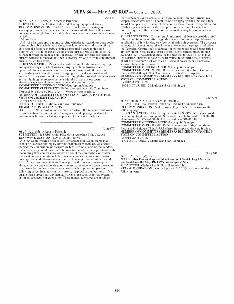
344
NFPA 86 — May 2003 ROP — Copyright, NFPA
(Log #43)86-55-(A-5-4.1.1 (New) ) : Accept in Principle SUBMITTER: Jim Houston, Industrial Heating Equipment Assn.RECOMMENDATION: 5-4.1.1* Prior to each furnace heating system start-up, provision shall be made for the removal of all flammable vapors and gases that might have entered the heating chambers during the shutdown period. Add to Annex: A-5-4.1.1 In some applications, purging with the furnace doors open could A-5-4.1.1 In some applications, purging with the furnace doors open could force combustible or indeterminate gasses into the work and surrounding force combustible or indeterminate gasses into the work and surrounding area near the furnace thereby creating a potential hazard to this area. area near the furnace thereby creating a potential hazard to this area. Purging with the doors closed would ensure furnace gasses exit out of the Purging with the doors closed would ensure furnace gasses exit out of the furnace through the intended flue or exhaust system. Igniting the furnace furnace through the intended flue or exhaust system. Igniting the furnace burners with the furnace doors open is an effective way to avoid containment burners with the furnace doors open is an effective way to avoid containment during the ignition cycle.during the ignition cycle.SUBSTANTIATION: Provide clear information for the correct prepurge and ignition sequences for furnaces. Purging with the furnace doors open could force combustible or indeterminate gasses into the work and surrounding area near the furnace. Purging with the doors closed would ensure furnace gasses out of the furnace through the intended flue or exhaust system. Igniting the furnace burners with the furnace doors open is an effective way to avoid containment during the ignition cycle.COMMITTEE MEETING ACTION:Accept in PrincipleCOMMITTEE STATEMENT: Refer to committee draft, Committee Proposal 86-1 (Log #CP1), A-7.4.1.1 where the text is added.NUMBER OF COMMITTEE MEMBERS ELIGIBLE TO VOTE:31VOTE ON COMMITTEE ACTION: AFFIRMATIVE: 29 NOT RETURNED: 2 Mattiola and vanHeijningenCOMMENT ON AFFIRMATIVE: COLLIER: With most automatic burner controls, the sequence continues to ignition directly after purge. The suggestion of opening the doors for ignition may be interpreted as a requirement that is not easily met.
————————————————-
(Log #70)86-56-(A-5-6.4) : Accept in Principle SUBMITTER: Ted Jablkowski, P.E., North American Mfg. Co., Ltd.RECOMMENDATION: Revise text as follows: A-5-6.4 Some systems work at very low combustion air pressures that Some systems work at very low combustion air pressures that cannot be detected reliably by conventional pressure switches. As a result, cannot be detected reliably by conventional pressure switches. As a result, many of the combustion air pressure switches are set at a value that renders many of the combustion air pressure switches are set at a value that renders them essentially out of the circuit. them essentially out of the circuit. In industrial combustion applications with modulating flow control valves downstream of the combustion air blower, it is most common to interlock the constant combustion air source pressure on single and multi-burner systems to meet the requirements of 5-6.2 and 5-6.4. Since the combustion air flow is proven during each purge cycle along with the combustion air source pressure, the most common convention is to prove the combustion air source pressure during burner operation following purge. In a multi-burner system, the proof of combustion air flow during purge proves that any manual valves in the combustion air system are in an adequately open position. These manual air valves are provided
for maintenance and combustion air flow balancing among burners in a temperature control zone. In combustion air supply systems that use either an inlet damper or speed control, the combustion air pressure may fall below reliably repeatable levels with listed pressure switch interlocks at low fire. For these systems, the proof of minimum air flow may be a more reliable interlock. SUBSTANTIATION: The present Annex material does not provide useful information in terms of offering guidance to a solution to the problem of the unreliability of interlocking very low combustion air pressures. The proposal to delete this Annex material and include new annex language is linked to the Technical Committee’s acceptance of the proposals to add combustion air flow interlocking as an alternate to source pressure interlocking in 5-6.2 and 5-6.4. The substantiation for the proposal to revise 5-6.4 is that the existing language is not clear with respect to requiring the assurance of either a minimum air flow, via a differential pressure, or air pressure, assumed to be a static pressure. COMMITTEE MEETING ACTION:Accept in PrincipleCOMMITTEE STATEMENT: Refer to the committee draft, Committee Proposal 86-1 (Log #CP1), A-7.6.4 where the text is incorporated.NUMBER OF COMMITTEE MEMBERS ELIGIBLE TO VOTE:31VOTE ON COMMITTEE ACTION: AFFIRMATIVE: 29 NOT RETURNED: 2 Mattiola and vanHeijningen
————————————————-
(Log #37)86-57-(Figure A-5-7.2.1) : Accept in Principle SUBMITTER: Jim Houston, Industrial Heating Equipment Assn.RECOMMENDATION: Add to annex, Figure A-5-7.2.1 shown on the following page.SUBSTANTIATION: Clarify requirements for SSOVs. See the proposed table to highlight main and pilot SSOV requirements for under 150,000 Btu/H, between 150,000 and 400,000 Btu/H and over 400,000 Btu/H.COMMITTEE MEETING ACTION:Accept in PrincipleCOMMITTEE STATEMENT: Refer to committee draft, Committee Proposal 86-1 (Log #CP1), A-7.7.2 where the proposed drawing is added.NUMBER OF COMMITTEE MEMBERS ELIGIBLE TO VOTE:31VOTE ON COMMITTEE ACTION: AFFIRMATIVE: 29 NOT RETURNED: 2 Mattiola and vanHeijningen
————————————————-
(Log #4)86-58-(A-5-7.2.3(a)) : Reject NOTE: This Proposal appeared as Comment 86-44 (Log #32) which was held from the May 1999 ROC on Proposal N/A.SUBMITTER: Christopher B. Fink, Honeywell Inc.RECOMMENDATION: Revise Figure A-5-7.2.3(a) as shown on the following page:
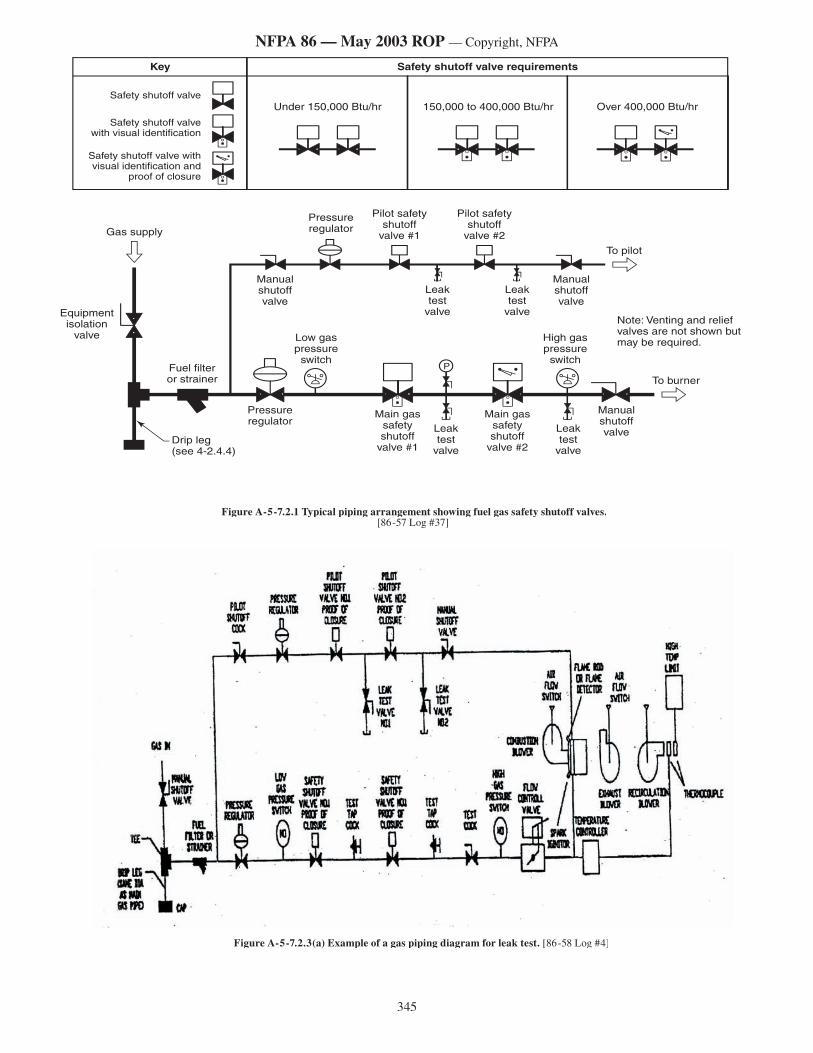
345
NFPA 86 — May 2003 ROP — Copyright, NFPA
Figure A-5-7.2.3(a) Example of a gas piping diagram for leak test. [86-58 Log #4]
Figure A-5-7.2.1 Typical piping arrangement showing fuel gas safety shutoff valves.[86-57 Log #37]
�������������������������
�����������������������
������������������
������������������
��������������������
��������������������
��������������������
��������������������������������
�����������������������������
����������������������������������������
�����������������������������������������������
����������������������������������������������������
����������������
������������������������� �������������������
�����������������������������
�������������
�������������
�������������
�������������
��������������������������������
�����������������������
������������������������
����������������������
������������������������������������������������������������������
���������
��������
����������
�
Key Safety shutoff valve requirements
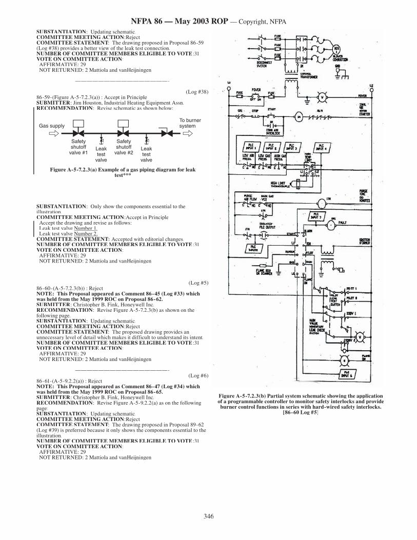
346
NFPA 86 — May 2003 ROP — Copyright, NFPA
SUBSTANTIATION: Updating schematic.COMMITTEE MEETING ACTION:RejectCOMMITTEE STATEMENT: The drawing proposed in Proposal 86-59 (Log #38) provides a better view of the leak test connection.NUMBER OF COMMITTEE MEMBERS ELIGIBLE TO VOTE:31VOTE ON COMMITTEE ACTION: AFFIRMATIVE: 29 NOT RETURNED: 2 Mattiola and vanHeijningen
————————————————-
(Log #38)86-59-(Figure A-5-7.2.3(a)) : Accept in Principle SUBMITTER: Jim Houston, Industrial Heating Equipment Assn.RECOMMENDATION: Revise schematic as shown below:
SUBSTANTIATION: Only show the components essential to the illustration.COMMITTEE MEETING ACTION:Accept in Principle Accept the drawing and revise as follows: Leak test valve Number 1. Leak test valve Number 2.COMMITTEE STATEMENT: Accepted with editorial changes.NUMBER OF COMMITTEE MEMBERS ELIGIBLE TO VOTE:31VOTE ON COMMITTEE ACTION: AFFIRMATIVE: 29 NOT RETURNED: 2 Mattiola and vanHeijningen
————————————————-
(Log #5)86-60-(A-5-7.2.3(b)) : Reject NOTE: This Proposal appeared as Comment 86-45 (Log #33) which was held from the May 1999 ROC on Proposal 86-62.SUBMITTER: Christopher B. Fink, Honeywell Inc.RECOMMENDATION: Revise Figure A-5-7.2.3(b) as shown on the following page.SUBSTANTIATION: Updating schematic.COMMITTEE MEETING ACTION:RejectCOMMITTEE STATEMENT: The proposed drawing provides an unnecessary level of detail which makes it difficult to understand its intent.NUMBER OF COMMITTEE MEMBERS ELIGIBLE TO VOTE:31VOTE ON COMMITTEE ACTION: AFFIRMATIVE: 29 NOT RETURNED: 2 Mattiola and vanHeijningen
————————————————-(Log #6)
86-61-(A-5-9.2.2(a)) : Reject NOTE: This Proposal appeared as Comment 86-47 (Log #34) which was held from the May 1999 ROC on Proposal 86-65.SUBMITTER: Christopher B. Fink, Honeywell Inc.RECOMMENDATION: Revise Figure A-5-9.2.2(a) as on the following page:SUBSTANTIATION: Updating schematic.COMMITTEE MEETING ACTION:RejectCOMMITTEE STATEMENT: The drawing proposed in Proposal 89-62 (Log #39) is preferred because it only shows the components essential to the illustration.NUMBER OF COMMITTEE MEMBERS ELIGIBLE TO VOTE:31VOTE ON COMMITTEE ACTION: AFFIRMATIVE: 29 NOT RETURNED: 2 Mattiola and vanHeijningen
————————————————-
����������
�����
��������������
��������
��������������
������������������
�����
��������������������������
Figure A-5-7.2.3(a) Example of a gas piping diagram for leak test***
Figure A-5-7.2.3(b) Partial system schematic showing the application of a programmable controller to monitor safety interlocks and provide burner control functions in series with hard-wired safety interlocks.
[86-60 Log #5]
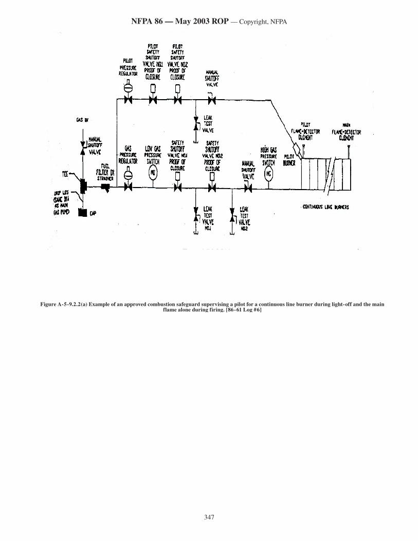
347
NFPA 86 — May 2003 ROP — Copyright, NFPA
Figure A-5-9.2.2(a) Example of an approved combustion safeguard supervising a pilot for a continuous line burner during light-off and the main flame alone during firing. [86-61 Log #6]
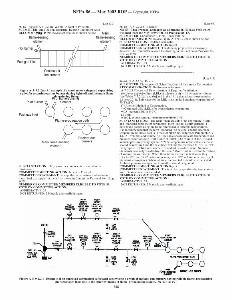
348
NFPA 86 — May 2003 ROP — Copyright, NFPA
(Log #39)86-62-(Figures A-5-9.2.2(a) & (b)) : Accept in Principle SUBMITTER: Jim Houston, Industrial Heating Equipment Assn.RECOMMENDATION: Revise schematics as shown below:
Figure A-5-9.2.2(a) An example of a combustion safeguard supervising a pilot for a continuous line burner during light-off and the main flame
alone during firing.
SUBSTANTIATION: Only show the components essential to the illustration.COMMITTEE MEETING ACTION:Accept in PrincipleCOMMITTEE STATEMENT: Accept the two drawings and revise to show “fuel gas supply” at the left as shown in Committee Proposal 86-1(Log #CP1).NUMBER OF COMMITTEE MEMBERS ELIGIBLE TO VOTE:31VOTE ON COMMITTEE ACTION: AFFIRMATIVE: 29 NOT RETURNED: 2 Mattiola and vanHeijningen
————————————————-
(Log #7)86-63-(A-5-9.2.2(b)) : Reject NOTE: This Proposal appeared as Comment 86-49 (Log #35) which was held from the May 1999 ROC on Proposal 86-65.SUBMITTER: Christopher B. Fink, Honeywell Inc.RECOMMENDATION: Revise Figure A-5-9.2.2.(b) as shown below:SUBSTANTIATION: Updated schematic.COMMITTEE MEETING ACTION:RejectCOMMITTEE STATEMENT: The drawing proposed is excessively detailed. The Committee revised the drawing in their action on Proposal 86-62 (Log #39).NUMBER OF COMMITTEE MEMBERS ELIGIBLE TO VOTE:31VOTE ON COMMITTEE ACTION: AFFIRMATIVE: 29 NOT RETURNED: 2 Mattiola and vanHeijningen
————————————————-
(Log #17)86-64-(A-7-5.2.3) : Reject SUBMITTER: Christopher G. Schaeffer, Control Instrument CorporationRECOMMENDATION: Revise text as follows: A-7-5.2.3 Theoretical Determination of Required Ventilation. (6) Lower explosive limit (LEL) of toluene in air = 1.1 percent by volume [see Tables 7-5.2.2(a) and (b)] and in the LEL calculations is expressed as 1.1 (not 0.011). This value for the LEL is at standardstandard ambient temperature of 70°F (21°C). (7) Another Method of Computation. 4) Corrected LEL (LEL
T 4) Corrected LEL (LEL
T 4) Corrected LEL (LEL ) for oven exhaust temperature: = 0.81 percent LEL at 149°C
Tpercent LEL at 149°C
Tpercent LEL at 149°Cpercent LEL at 149°C
SI Units = 200 L xylene vapor at standard conditionsstandard conditions 21°C SUBSTANTIATION: The term “standard cubic feet per minute” (scfm) and “standard cubic meter per minute” (scm) are not clearly defined. I have found parties using the terms referenced to different temperatures. It is recommended that the term “standard” be deleted, and the reference temperature be stated as it is in most of NFPA 86. Reference Paragraph A-7-4.1. All volumes and volumetric flow value should indicate temperature and pressure conditions [e.g., 100 ft3/min at 300°F(2.83 m3/min at 148.9°C and ambient pressure] Paragraph A-7.5 “The temperature of the exhaust air also should be measured and the calculated volume the corrected to 70°F (21°C)”. Paragraph 2.1 Definitions, refers to “standard” as a document. National Standards have only standardized the term “Mole”, that is used for derivation of volume measurements. When these terms are used in textbooks they refer to 32°F and 29.92 inches of mercury, also 0°C and 760 mm mercury (1 Standard atmosphere). Where altitude is corrected it should also be stated. Ambient pressure changes due to weather should be ignored.COMMITTEE MEETING ACTION:RejectCOMMITTEE STATEMENT: The text clearly specifies the temperature used. Restatement is not needed.NUMBER OF COMMITTEE MEMBERS ELIGIBLE TO VOTE:31VOTE ON COMMITTEE ACTION: AFFIRMATIVE: 29 NOT RETURNED: 2 Mattiola and vanHeijningen
————————————————-
Figure A-5-9.2.2(a) Example of an approved combustion safeguard supervising a group of radiant-cup burners having reliable flame-propagation characteristics from one to the other by means of flame-propagation devices. [86-63 Log #7]
Main flame-sensing
element
Pilot flame-sensing
element
Continuous line burners
Pilot burner
Fuel gas inlet
Main flame-sensing element
Radiant-cup burners
Pilot flame-sensing element
Flame-propagation path
Pilot burner
Fuel gas inlet
349
NFPA 86 — May 2003 ROP — Copyright, NFPA
(Log #18)86-65-(A-7-5.2.4) : Accept in Principle SUBMITTER: Christopher G. Schaeffer, Control Instrument CorporationRECOMMENDATION: Revise text as follows: The basis for the general rule is that 1 gal of typical solvent produces a quantity of flammable vapor that, when diffused in air, forms approximately 2640 scfscf scf scf ft3 at 70°F of a lean mixture that is barely explosive. One L of a typical solvent forms approximately 19.75 standardstandard m3 at 21°C of a lean mixture that is barely explosive. Refer to Tables 7-5.2.2(a) and (b). The value of 12,000 ft3 (340 m3) includes a factor to account for LEL correction at 350°F (177°C). SUBSTANTIATION: The term “standard cubic feet per minute” (scfm) and “standard cubic meter per minute” (scm) are not clearly defined. I have found parties using the terms referenced to different temperatures. It is recommended that the term “standard” be deleted, and the reference temperature be stated as it is in most of NFPA 86. Reference Paragraph A-7-4.1. All volumes and volumetric flow value should indicate temperature and pressure conditions [e.g., 100 ft3/min at 300°F(2.83 m3/min at 148.9°C and ambient pressure] Paragraph A-7.5 “The temperature of the exhaust air also should be measured and the calculated volume the corrected to 70°F (21°C)”. Paragraph 2.1 Definitions, refers to “standard” as a document. National Standards have only standardized the term “Mole”, that is used for derivation of volume measurements. When these terms are used in textbooks they refer to 32°F and 29.92 inches of mercury, also 0°C and 760 mm mercury (1 Standard atmosphere). Where altitude is corrected it should also be stated. Ambient pressure changes due to weather should be ignored.COMMITTEE MEETING ACTION:Accept in PrincipleCOMMITTEE STATEMENT: Refer to Committee Action on Proposal 86-38 (Log # 12).NUMBER OF COMMITTEE MEMBERS ELIGIBLE TO VOTE:31VOTE ON COMMITTEE ACTION: AFFIRMATIVE: 29 NOT RETURNED: 2 Mattiola and vanHeijningen
————————————————-
(Log #19)86-66-(A-7-5.4) : Accept in Principle SUBMITTER: Christopher G. Schaeffer, Control Instrument CorporationRECOMMENDATION: Revise text as follows: Exhaust calculated for products of combustion (see 7-5.3): [Note: The following are found in formulas.] 183 scfmscfm ft3 at 70°F; (scfm)scfm)Safety ventilation required for constituents released in oven: (scfm)(scfm) = 814 ft3 air/min (scfm)(scfm) at 70°F to be corrected for oven operating temperature = 10.36 m3 air/min at 21°C (standard m(standard m33/min)/min) …………..= 0.84 percent LELpercent LEL = 12.68 m3 air/min at 21°C (standard m(standard m33/min) /min) SUBSTANTIATION: The term “standard cubic feet per minute” (scfm) and “standard cubic meter per minute” (scm) are not clearly defined. I have found parties using the terms referenced to different temperatures. It is recommended that the term “standard” be deleted, and the reference temperature be stated as it is in most of NFPA 86. Reference Paragraph A-7-4.1. All volumes and volumetric flow value should indicate temperature and pressure conditions [e.g., 100 ft3/min at 300°F(2.83 m3/min at 148.9°C and ambient pressure] Paragraph A-7.5 “The temperature of the exhaust air also should be measured and the calculated volume the corrected to 70°F (21°C)”. Paragraph 2.1 Definitions, refers to “standard” as a document. National Standards have only standardized the term “Mole”, that is used for derivation of volume measurements. When these terms are used in textbooks they
refer to 32°F and 29.92 inches of mercury, also 0°C and 760 mm mercury (1 Standard atmosphere). Where altitude is corrected it should also be stated. Ambient pressure changes due to weather should be ignored.COMMITTEE MEETING ACTION:Accept in PrincipleCOMMITTEE STATEMENT: Refer to Committee Action on Proposal 86-38 (Log # 12).NUMBER OF COMMITTEE MEMBERS ELIGIBLE TO VOTE:31VOTE ON COMMITTEE ACTION: AFFIRMATIVE: 29 NOT RETURNED: 2 Mattiola and vanHeijningen
————————————————-
(Log #20)86-67-(A-7-6) : Accept in Principle SUBMITTER: Christopher G. Schaeffer, Control Instrument CorporationRECOMMENDATION: Revise text as follows: A-7-6 Sample Calculations for Batch Ovens. (440 scfmscfm ft3/min at 70°F)………= 1848 scfmscfm ft3 at 70°F air…..3.29 standardstandard m3 at 21°C= 52.5 standardstandard m3/min of 21°C air2800 standardstandard ft3 /min 70°F…= 168 scfmscfm ft3/min at 70°F mixture at LELSafety ventilation calculation:……168 scfmscfm ft3/min at 70°FCorrection for oven temperature:……(941 scfm ft3/min at 70°F)Barely flammable mixture at peak evaporation rate [see Tables 7-5.2.2(a) and (b)]:…………21.04 standardstandard m3/min air at 21°C= 4.78 standardstandard m3/min LEL mixture at 21°C 4 (factor of safety) 1.4 (LEL temperature adjustment) = 26.77 standardstandard m3/min at 21°CCorrection for oven temperature:……….26.77 standardstandard m3/min at 21°C= 6523 standardstandard ft3/hr LEL mixture at 70°FCalculated ventilation volume:……..6523 scfmscfm ft3/min at 70°F x 10/60 x 1.4 (LEL temp. adjustment) = 1522 scfmscfm ft3/min of 70°F air SUBSTANTIATION: The term “standard cubic feet per minute” (scfm) and “standard cubic meter per minute” (scm) are not clearly defined. I have found parties using the terms referenced to different temperatures. It is recommended that the term “standard” be deleted, and the reference temperature be stated as it is in most of NFPA 86. Reference Paragraph A-7-4.1. All volumes and volumetric flow value should indicate temperature and pressure conditions [e.g., 100 ft3/min at 300°F(2.83 m3/min at 148.9°C and ambient pressure] Paragraph A-7.5 “The temperature of the exhaust air also should be measured and the calculated volume the corrected to 70°F (21°C)”. Paragraph 2.1 Definitions, refers to “standard” as a document. National Standards have only standardized the term “Mole”, that is used for derivation of volume measurements. When these terms are used in textbooks they refer to 32°F and 29.92 inches of mercury, also 0°C and 760 mm mercury (1 Standard atmosphere). Where altitude is corrected it should also be stated. Ambient pressure changes due to weather should be ignored.COMMITTEE MEETING ACTION:Accept in PrincipleCOMMITTEE STATEMENT: Refer to Committee Action on Proposal 86-38 (Log # 12).NUMBER OF COMMITTEE MEMBERS ELIGIBLE TO VOTE:31VOTE ON COMMITTEE ACTION: AFFIRMATIVE: 29 NOT RETURNED: 2 Mattiola and vanHeijningen
————————————————-
350
NFPA 86 — May 2003 ROP — Copyright, NFPA
DRAFT
NFPA 86
Standard for Ovens and Furnaces
2003 Edition
NOTICE: An asterisk (*) following the number or letter designating a paragraph indicates that explanatory material on the paragraph can be found in Annex A.
Information on referenced publications can be found in Chapter 2 and Annex N.
Chapter 1 Administration
1.1 Scope.
1.1.1 This standard shall apply to Class A, Class B, Class C, and Class D ovens, dryers, or furnaces. The terms ovens, dryers, and furnaces shall be used interchangeably. Where chapters or specific paragraphs in this standard apply only to Class A, B, C, or D ovens, they are so noted.
1.1.2 Within the scope of this standard, Class A, B, or C ovens shall be any heated enclosure operating at approximately atmospheric pressure and used for commercial and industrial processing of materials.
1.1.3 A Class A oven also shall be permitted to utilize a low-oxygen atmosphere.
1.1.4 This standard also shall apply to bakery ovens, a Class A oven, in all respects, and reference is made to those sections of ANSI Z50.1, Bakery Equipment — Safety Requirements, that shall apply to bakery oven construction and safety.
1.1.5 This standard shall apply to atmosphere generators and atmosphere supply systems serving Class C furnaces. Also included are furnaces with integral quench tanks or molten salt baths.
1.1.6* This standard shall apply to Class D ovens and furnaces operating above ambient temperatures to over 5000°F (2760°C) and at pressures normally below atmospheric to 10-8 torr (1.33 10-6 Pa).
1.1.7 This standard shall not apply to the following:
(1) Coal or other solid fuel-firing systems
(2) Listed equipment with a heating system(s) that supplies a total input not exceeding 150,000 Btu/hr (44 kW). (See definition of Listed in Chapter 3.)
1.2* Purpose. This standard provides the requirements for the prevention of fire and explosion hazards associated with the heat processing of materials in ovens, furnaces, and related equipment. The heat processing of materials involves serious fire and explosion hazards that can endanger the furnace, the building, or personnel.
1.3 Application.
1.3.1 The requirements of Chapters 1 through 8 shall apply to equipment described in subsequent chapters except as modified by those chapters.
1.3.2* This entire standard shall apply to new installations or alterations or extensions to existing equipment.
1.3.3 Section 4.2 and Chapter 14 shall apply to all operating furnaces.
1.4 Retroactivity. The provisions of this standard reflect a consensus of what is necessary to provide an acceptable degree of protection from the hazards addressed in this standard at the time the standard was issued.
Unless otherwise specified, the provisions of this standard shall not apply to facilities, equipment, structures, or installations that existed or were approved for construction or installation prior to the effective date of the standard. Where specified, the provisions of this standard shall be retroactive.
In those cases where the authority having jurisdiction determines that the existing situation presents an unacceptable degree of risk, the authority having jurisdiction shall be permitted to apply retroactively any portions of this standard deemed appropriate.
The retroactive requirements of this standard shall be permitted to be modified if their application clearly would be impractical in the judgement of the authority having jurisdiction, and only where it is clearly evident that a reasonable degree of safety is provided.
1.5* Equivalency. Nothing in this standard is intended to prevent the use of systems, methods, or devices of equivalent or superior quality, strength, fire resistance, effectiveness, durability, and safety over those prescribed by
this standard. Technical documentation shall be submitted to the authority having jurisdiction to demonstrate equivalency. The system, method, or device shall be approved for the intended purpose by the authority having jurisdiction.
1.6 Units and Formulas.
1.6.1 SI Units. Metric units of measurement in this standard are in accordance with the modernized metric system known as the International System of Units (SI).
1.6.2 Primary and Equivalent Values. If a value for a measurement as given in this standard is followed by an equivalent value in other units, the first stated value shall be regarded as the requirement. A given equivalent value might be approximate.
1.6.3 Conversion Procedure. SI units have been converted by multiplying the quantity by the conversion factor and then rounding the result to the appropriate number of significant digits.
Chapter 2 Referenced Publications
2.1 General. The documents or portions thereof listed in this chapter are referenced within this standard and shall be considered part of the requirements of this document.
2.2 NFPA Publications. National Fire Protection Association, 1 Batterymarch Park, P.O. Box 9101, Quincy, MA 02269-9101.
NFPA 10, Standard for Portable Fire Extinguishers, 1998 edition.
NFPA 11, Standard for Low-Expansion Foam, 1998 edition.
NFPA 12, Standard on Carbon Dioxide Extinguishing Systems, 2000 edition.
NFPA 13, Standard for the Installation of Sprinkler Systems, 1999 edition.
NFPA 15, Standard for Water Spray Fixed Systems for Fire Protection, 2001 edition.
NFPA 17, Standard for Dry Chemical Extinguishing Systems, 1998 edition.
NFPA 17A, Standard for Wet Chemical Extinguishing Systems, 1998 edition.
NFPA 25, Standard for the Inspection, Testing, and Maintenance of Water-Based Fire Protection Systems, 2002 edition.
NFPA 30, Flammable and Combustible Liquids Code, 2000 edition.
NFPA 31, Standard for the Installation of Oil-Burning Equipment, 2001 edition.
NFPA 50, Standard for Bulk Oxygen Systems at Consumer Sites, 2001 edition.
NFPA 50A , Standard for Gaseous Hydrogen Systems at Consumer Sites, 1999 edition.
NFPA 50B, Standard for Liquefied Hydrogen Systems at Consumer Sites, 1999 edition.
NFPA 54, National Fuel Gas Code, 1999 edition.
NFPA 58, Liquefied Petroleum Gas Code, 2001 edition.
NFPA 70, National Electrical Code®, 2002 edition.
NFPA 79, Electrical Standard for Industrial Machinery, 1997 edition.
NFPA 91, Standard for Exhaust Systems for Air Conveying of Vapors, Gases, Mists, and Noncombustible Particulate Solids, 1999 edition.
NFPA 750, Standard on Water Mist Fire Protection Systems, 2000 edition.
2.3 Other Publications.
2.3.1 ANSI Publications. American National Standards Institute, Inc., 11 West 42nd Street, 13th floor, New York, NY 10036.
ANSI Z50.1, Bakery Equipment — Safety Requirements, 2000.
2.3.2 ASME Publications. American Society of Mechanical Engineers, Three Park Avenue, New York, NY 10016-5990.
ASME Boiler and Pressure Vessel Code, 2001.
ASME B31.1, Power Piping, 2001.
ASME B31.3, Process Piping, 1999.
351
NFPA 86 — May 2003 ROP — Copyright, NFPA
DRAFT
2.3.3 ASTM Publication. American Society for Testing and Materials, 100 Barr Harbor Drive, West Conshohocken, PA 19428-2959.
ASTM D 396, Standard Specifications for Fuel Oils, 2001.
2.3.4 U.S. Government Publication. U.S. Government Printing Office, Washington, DC 20402.
Chapter 3 Definitions
3.1 General. The definitions contained in this chapter shall apply to the terms used in this standard. Where terms are not included, common usage of the terms shall apply.
3.2 NFPA Official Definitions.
3.2.1* Approved. Acceptable to the authority having jurisdiction.
3.2.2* Authority Having Jurisdiction (AHJ). The organization, office, or individual responsible for approving equipment, materials, an installation, or a procedure.
3.2.3 Labeled. Equipment or materials to which has been attached a label, symbol, or other identifying mark of an organization that is acceptable to the authority having jurisdiction and concerned with product evaluation, that maintains periodic inspection of production of labeled equipment or materials, and by whose labeling the manufacturer indicates compliance with appropriate standards or performance in a specified manner.
3.2.4* Listed. Equipment, materials, or services included in a list published by an organization that is acceptable to the authority having jurisdiction and concerned with evaluation of products or services, that maintains periodic inspection of production of listed equipment or materials or periodic evaluation of services, and whose listing states that either the equipment, material, or service meets appropriate designated standards or has been tested and found suitable for a specified purpose.
3.2.5 Shall. Indicates a mandatory requirement.
3.2.6 Should. Indicates a recommendation or that which is advised but not required.
3.2.7 Standard. A document, the main text of which contains only mandatory provisions using the word “shall” to indicate requirements and which is in a form generally suitable for mandatory reference by another standard or code or for adoption into law. Nonmandatory provisions shall be located in an appendix or annex, footnote, or fine-print note and are not to be considered a part of the requirements of a standard.
3.3 General Definitions.
3.3.1 Afterburner. See 3.3.47.2 Thermal Oxidizer.
3.3.2 Air.
3.3.2.1 Combustion Air. All the air introduced with fuel to supply heat in a furnace.
3.3.2.2 Primary Air. All air supplied through the burner.
3.3.2.3 Reaction Air. All the air that, when reacted with gas in an endothermic generator by the indirect addition of heat, becomes a special atmosphere gas.
3.3.2.4 Secondary Air. All the combustion air that is intentionally allowed to enter the combustion chamber in excess of primary air.
3.3.3 Automatic Fire Check. A flame arrester equipped with a check valve to shut off the fuel gas supply automatically if a backfire occurs.
3.3.4 Backfire Arrester. A flame arrester installed in fully premixed air–fuel gas distribution piping to terminate flame propagation therein, shut off fuel supply, and relieve pressure resulting from a backfire.
3.3.5 Burner. A device or group of devices used for the introduction of fuel, air, oxygen, or oxygen-enriched air into a furnace at the required velocities, turbulence, and concentration to maintain ignition and combustion of fuel.
3.3.5.1 Atmospheric Burner. A burner used in the low-pressure fuel gas or atmospheric system that requires secondary air for complete combustion.
3.3.5.2 Atomizing Burner. A burner in which oil is divided into a fine spray by an atomizing agent, such as steam or air.
3.3.5.3 Blast Burner. A burner delivering a combustible mixture under pressure, normally above 0.3 in. w.c. (75 kPa), to the combustion zone.
3.3.5.4 Combination Fuel Gas and Oil Burner. A burner that can burn either fuel gas or oil, or both simultaneously.
3.3.5.5 Dual-Fuel Burner. A burner designed to burn either fuel gas or oil, but not both simultaneously.
3.3.5.6 Line Burner. A burner whose flame is a continuous line.
3.3.5.7 Multiple-Port Burner. A burner having two or more separate discharge openings or ports.
3.3.5.8 Nozzle Mixing Burner. A burner in which the fuel and air are introduced separately to the point of ignition.
3.3.5.9 Premix Burner. A burner in which the fuel and air are mixed prior to the point of ignition.
3.3.5.10 Pressure Atomizing Burner. A burner in which oil under high pressure is forced through small orifices to emit liquid fuel in a finely divided state.
3.3.5.11 Radiant Burner. A burner designed to transfer a significant part of the combustion heat in the form of radiation.
3.3.5.12 Radiant Tube Burner. A burner designed to provide a long flame within a tube to ensure substantially uniform radiation from the tube surface.
3.3.5.13 Rotary Atomizing Burner. A burner in which oil is atomized by applied centrifugal force, such as by a whirling cone or plate.
3.3.5.14 Self-Piloted Burner. A burner in which the pilot fuel is issued from the same ports as the main flame or merges with the main flame to form a common flame envelope with a common flame base.
3.3.6 Burner System. One or more burners operated as a unit by a common safety shut-off valve(s).
3.3.7 Burner Turndown. The ratio of maximum to minimum burner fuel-input rates.
3.3.8 Burn-In. The procedure used in starting up a special atmosphere furnace to replace air within the heating chamber(s) and vestibule(s) with flammable special atmosphere.
3.3.9 Burn-Out. The procedure used in shutting down or idling a special atmosphere to replace flammable atmosphere within the heating chamber(s) and vestibule(s) with a nonflammable atmosphere.
3.3.10 Combustion Safeguard. A safety control directly responsive to flame properties; it senses the presence or absence of flame and de-energizes the fuel safety valve in the event of flame failure within 4 seconds of the loss of flame signal.
3.3.11 Combustion Safety Circuitry. That portion of the oven control circuitry that contains the contacts for the required safety interlocks and the excess temperature limit controller(s). These contacts are arranged in series ahead of the safety shut-off valve(s) holding medium.
3.3.12 Controller.
3.3.12.1 Continuous Vapor Concentration High Limit Controller. A safety device designed to initiate reduction of the vapor concentration if the concentration exceeds a predetermined set point.
3.3.12.2 Continuous Vapor Concentration Controller. A device that measures, indicates, and directly or indirectly controls the concentration of a flammable vapor-air mixture as expressed in percentage of the lower explosive limit (LEL).
3.3.12.3 Excess Temperature Limit Controller. A device designed to cut off the source of heat if the operating temperature exceeds a predetermined temperature set point.
3.3.12.4 Programmable Controller. A digital electronic system designed for use in an industrial environment that uses a programmable memory for the internal storage of user-oriented instructions for implementing specific functions to control, through digital or analog inputs and outputs, various types of machines or processes.
3.3.12.5 Temperature Controller. A device that measures the temperature and automatically controls the input of heat into the furnace.
3.3.13* Cut-Away Damper. A restricting airflow device that, when placed in the maximum closed position, allows a minimum amount of airflow past the restriction.
3.3.14* Cryogenic Fluid. A fluid produced or stored at very low temperatures.
3.3.15 Direct-Fired Air Makeup Unit. A Class B fuel-fired heat utilization unit operating at approximately atmospheric pressure used to heat outside replacement air for the process.
3.3.16* Explosion-Resistant (Radiant Tube). A radiant tube or radiant tube heat recovery system that does not fail catastrophically when subjected to the maximum deflagration pressure caused by the ignition of an accumulation of a stoichiometric mixture of the selected fuel(s) and air.
352
NFPA 86 — May 2003 ROP — Copyright, NFPA
DRAFT
3.3.17* Explosive Range. The range of concentration of a flammable gas in air within which a flame can be propagated. The lowest flammable concentration is the lower explosive limit (LEL). The highest flammable concentration is the upper explosive limit
3.3.18 Flame Arrester. A device installed in the small branch piping of a fully premixed air–fuel gas mixture to retard a flame front originating from a backfire.
3.3.19* Flame Propagation Rate. The speed at which a flame progresses through a combustible fuel-air mixture.
3.3.20 Flame Rod. A detector that employs an electrically insulated rod of temperature-resistant material that extends into the flame being supervised, with a voltage impressed between the rod and a ground connected to the nozzle or burner. The resulting electrical current, which passes through the flame, is rectified, and this rectified current is detected and amplified by the combustion safeguard.
3.3.21 Fuel Gas. Gas used for heating, such as natural gas, manufactured gas, undiluted liquefied petroleum gas (vapor phase only), liquefied petroleum gas–air mixtures, or mixtures of these gases.
3.3.22 Fuel Gas System.
3.3.22.1 High Pressure Fuel Gas System. A system using the kinetic energy of a jet of 1 psig (7 kPa) or higher gas pressure to entrain from the atmosphere all, or nearly all, the air required for combustion.
3.3.22.2 Low Pressure or Atmospheric Fuel Gas System. A system using the kinetic energy of a jet of less than 1 psig (7 kPa) gas pressure to entrain from the atmosphere a portion of the air required for combustion.
3.3.23 Fuel Oil. Grades 2, 4, 5, or 6 fuel oils as defined in ASTM D 396, Standard Specifications for Fuel Oils.
3.3.24 Fume Incinerator. Any separate or independent combustion equipment or device that entrains the process exhaust for the purpose of direct thermal or catalytic destruction, which can include heat recovery.
3.3.25 Furnace.
3.3.25.1 Atmosphere Furnace. A furnace built to allow heat processing of materials in a special processing atmosphere.
3.3.25.2 Batch Furnace. A furnace into which the work charge is introduced all at once.
3.3.25.3* Class A Furnace. An oven or furnace that has heat utilization equipment operating at approximately atmospheric pressure wherein there is a potential explosion or fire hazard that could be occasioned by the presence of flammable volatiles or combustible materials processed or heated in the furnace.
3.3.25.4 Class B Furnace. An oven or furnace that has heat utilization equipment operating at approximately atmospheric pressure wherein there are no flammable volatiles or combustible materials being heated.
3.3.25.5* Class C Furnace. An oven or furnace that has a potential hazard due to a flammable or other special atmosphere being used for treatment of material in process.
3.3.25.6* Class D Furnace. An oven or furnace that operates at temperatures above ambient to over 5000°F (2760°C) and at pressures from vacuum to several atmospheres during heating using any type of heating system. These furnaces can include the use of special processing atmospheres.
3.3.25.7 Continuous Furnace. A furnace into which the work charge is more or less continuously introduced.
3.3.25.8 Molten Salt Bath Furnace. A furnace that employs salts heated to a molten state. These do not include aqueous alkaline baths, hot brine, or other systems utilizing salts in solution.
3.3.25.9 Plasma Arc Furnace. A furnace that employs the passage of an electric current between either a pair of electrodes or between electrodes and the work, and ionizing a gas (such as argon) and transferring energy in the form of heat.
3.3.26 Gas.
3.3.26.1 Ballast Gas. Atmospheric air or a dry gas that is admitted into the compression chamber of rotary mechanical pumps to prevent condensation of vapors in the pump oil by maintaining the partial pressure of the condensable vapors below the saturation value (also called vented exhaust).
3.3.26.2 Inert Gas. See Special Atmosphere, Inert (Purge Gas).
3.3.26.3 Reaction Gas. A gas that, when reacted with air in an endothermic generator by the addition of heat, becomes a special atmosphere gas.
3.3.27 Gas Analyzer. A device that measures concentrations, directly or indirectly, of some or all components in a gas or mixture.
3.3.28* Gas Quenching. The introduction of a gas, usually nitrogen or argon (in certain situations helium or hydrogen can be used), into the furnace to a specific pressure [usually between – 2.5 psig to 15 psig (0.85 bar to 2.05 bar)] for the purpose of cooling the work.
3.3.28.1 High Pressure Gas Quenching. Gas-cooling at pressures greater than 15 psig.
3.3.29 Guarded. Covered, shielded, fenced, enclosed, or otherwise protected by such means as covers or casings, barriers, rails or screens, mats, or platforms.
3.3.30 Heater.
3.3.30.1* Dielectric Heater. A heater similar to an induction heater, but using frequencies that generally are higher (3 MHz or more) than those used in induction heating.
3.3.30.2 Direct-Fired External Heater. A heating system in which the burners are in a combustion chamber effectively separated from the work chamber and arranged so that products of combustion from the burners are discharged into the work chamber by a circulating fan or blower.
3.3.30.3 Direct-Fired Internal Heater. A heating system in which the burners are located within the work chamber.
3.3.31 Heating System.
3.3.31.1* Direct-Fired Heating System. A heating system in which the products of combustion enter the work chamber.
3.3.31.2 Indirect-Fired Heating System. A heating system in which the products of combustion do not enter the work chamber.
3.3.31.3* Indirect-Fired Internal Heating System. A heating system of gastight radiators containing burners not in contact with the oven atmosphere.
3.3.31.4 Induction Heating System. A heating system by means of which a current-carrying conductor induces the transfer of electrical energy to the work by eddy currents. (See NFPA 70, National Electrical Code, Article 665.)
3.3.31.5 Radiant Tube Heating System. A heating system with tubular elements open at one or both ends. Each tube has an inlet burner arrangement where combustion is initiated, a suitable length where combustion occurs, and an outlet for the combustion products formed.
3.3.31.6* Resistance Heating System. A system in which heat is produced by current flow through a resistive conductor.
3.3.31.7 Tubular Heating System. A form of radiant heater in which resistive conductors are enclosed in glass, quartz, or ceramic envelopes that can contain a special gas atmosphere.
3.3.32 Ignition Temperature. The lowest temperature at which a gas-air mixture can ignite and continue to burn. This also is referred to as the autoignition temperature.
3.3.33* Implosion. The rapid inward collapsing of the walls of a vacuum component or device as the result of failure of the walls to sustain the atmospheric pressure.
3.3.34 Interlock.
3.3.34.1 Proved Low-Fire Start Interlock. A burner start interlock in which a control sequence ensures that a high–low or modulated burner is at a reduced firing rate for reliable ignition before the burner can be ignited.
3.3.34.2 Safety Interlock. A device required to ensure safe start-up and safe operation and to cause safe equipment shutdown.
3.3.35* Limiting Oxidant Concentration (LOC). The concentration of oxidant below which a deflagration cannot occur.
3.3.36 LOC. See Limiting Oxidant Concentration.
3.3.37 Lower Explosive Limit (LEL). See 3.3.17 Explosive Range.
3.3.38 Mixer.
3.3.38.1* Air Jet Mixer. A mixer using the kinetic energy of a stream of air issuing from an orifice to entrain the fuel gas required for combustion.
3.3.38.2 Air–Fuel Gas Mixer. A system that combines air and fuel gas in the proper proportion for combustion.
3.3.38.3 Gas Jet Mixer [Atmospheric Inspirator (Venturi) Mixer]. A mixer using the kinetic energy of a jet of fuel gas issuing from an orifice to entrain all or part of the air required for combustion.
353
NFPA 86 — May 2003 ROP — Copyright, NFPA
DRAFT
3.3.38.4 Proportional Mixer. A mixer comprised of an inspirator that, when supplied with air, draws all the fuel gas necessary for combustion into the airstream, and a governor, zero regulator, or ratio valve that reduces incoming fuel gas pressure to approximately atmospheric.
3.3.39 Mixing Blower. A motor-driven blower to supply air–fuel gas mixtures for combustion through one or more fuel burners or nozzles on a single-zone industrial heating appliance or on each control zone of a multizone installation. Mixing machines operated at 10 in. w.c. (2.49 kPa) or less static pressure are considered mixing blowers.
3.3.40 Mixing Machine. A mixer using mechanical means to mix fuel and air and to compress the resultant mixture to a pressure suitable for delivery to its point of use. Mixers in this group utilize either a centrifugal fan or some other type of mechanical compressor with a proportioning device on its intake through which fuel and air are drawn by the fan or compressor suction.
3.3.41 Muffles. Enclosures within a furnace to separate the source of heat from the work and from any special atmosphere that might be required for the process.
3.3.42 Molten Bath Salt. See 3.3.25.8 Molten Salt Bath Furnace.
3.3.43 Oil Separator. An oil reservoir with baffles used to minimize the discharge of oil mist from the exhaust of a rotary mechanical vacuum pump.
3.3.44 Operator. An individual trained and responsible for the start-up, operation, shutdown, and emergency handling of the furnace and associated equipment.
3.3.45 Outgassing. The release of adsorbed or occluded gases or water vapor, usually by heating, such as from a vacuum tube or other vacuum system.
3.3.46 Oven. See 3.3.25.1 through 3.3.25.9, Furnace definitions.
3.3.46.1* Low-Oxygen Oven. An oven that utilizes a low-oxygen atmosphere to evaporate solvent to facilitate solvent recovery.
3.3.47 Oxidizer.
3.3.47.1 Catalytic Oxidizer. See 3.3.47.2 Thermal Oxidizer.
3.3.47.2 Thermal Oxidizer. An independently controlled, enclosed combustion system whose purpose is to destroy volatile organic compound (VOC) and/or hydrocarbon (HC) gases or vapors using elevated temperature, residence time, mixing, excess oxygen, and in some cases, catalysts.
3.3.47.2.1 Afterburner. A direct thermal oxidizer, installed in series, downstream of process equipment that generates VOC or HC. It is sometimes called a “secondary combustion chamber.”
3.3.47.2.2 Direct Catalytic Oxidizer. A combustion device where the burner(s) directly heat the VOCs or HCs to the destruction temperature, prior to their introduction to a destruction catalyst, without heat recovery to the incoming gases. The catalytic destruction temperature is lower than the non-catalytic (direct thermal) destruction temperature.
3.3.47.2.3 Direct Thermal Oxidizer (TO). A combustion device where the burner(s) directly heat the VOCs or HCs to the destruction temperature without heat recovery to the incoming gases.
3.3.47.2.4 Flameless Thermal Oxidizer (FTO). A combustion device where the burner preheats the heat storage media prior to the introduction of the VOCs or HCs, and subsequently the destruction is carried out in the interstices of the heat storage media in a flameless, self-sustaining manner. FTOs can be direct recuperative or regenerative.
3.3.47.2.5 Recuperative Catalytic Oxidizer. A combustion device where the burner(s) directly heat the VOCs or HCs to the catalytic destruction temperature prior to their introduction to a destruction catalyst and after which the products of combustion are used to indirectly heat the incoming gas stream before it contacts the burner flame. The catalytic destruction temperature is lower than the non-catalytic (direct thermal) destruction temperature.
3.3.47.2.6 Recuperative Thermal Oxidizer. A combustion device where the burner(s) directly heat the VOCs or HCs to the destruction temperature and the hot products of combustion are used to indirectly heat the incoming gas stream before it contacts the burner flame.
3.3.47.2.7 Regenerative Catalytic Oxidizer (RCO). A combustion device where the burner(s) can directly heat the VOCs or HCs after the gas stream is preheated to the destruction temperature by the periodic flow reversal of the gas stream through catalytically coated heat storage media that alternately have been heated by the product gases during an exhaust cycle and then have given up their heat to the incoming reactant gases during an inlet cycle.
3.3.47.2.8 Regenerative Thermal Oxidizer (RTO). A combustion device where the burner(s) can directly heat the VOCs or HCs after the gas stream
is preheated to the destruction temperature by the periodic flow reversal of the gas stream through heat storage media that alternately have been heated by the product gases during an exhaust cycle and then have given up their heat to the incoming reactant gases during an inlet cycle.
3.3.48 Pilot. A flame that is used to light the main burner.
3.3.48.1 Burn-off Pilot. A pilot that ignites the flame curtain or special processing atmosphere discharging from the furnace or generator.
3.3.48.2 Continuous Pilot. A pilot that burns throughout the entire period that the heating equipment is in service, whether or not the main burner is firing.
3.3.48.3 Expanding Pilot. A pilot that burns at a set turndown throughout the entire period that the heating equipment is in service, but burns without turndown during light-off of the main burner.
3.3.48.4 Intermittent Pilot. A pilot that burns during light-off and while the main burner is firing.
3.3.48.5 Interrupted Pilot. A pilot that is ignited and burns during light-off and is automatically shut off at the end of the trial-for-ignition period of the main burner(s).
3.3.48.6 Proved Pilot. A pilot flame supervised by a combustion safeguard that senses the presence of the pilot flame.
3.3.49 Pilot Flame Establishing Period. The interval of time during light-off that a safety-control circuit allows the pilot fuel safety shut-off valve to remain open before the combustion safeguard proves the presence of the pilot flame.
3.3.50 Plasma Arc. A heating process where an ionized gas, such as nitrogen or argon, is used to conduct electrical current.
3.3.51 Pressure.
3.3.51.1 Partial Pressure. The pressure that is exerted by one component of a mixture of gases if it is present alone in a container.
3.3.51.2 Ultimate Pressure. The limiting pressure approached in the vacuum system after sufficient pumping time to establish that further reductions in pressure would be negligible (sometimes called the ultimate vacuum).
3.3.52 Pressure Regulator. A device that maintains a constant outlet pressure under varying flow.
3.3.53 Proven Ventilation. A supply of fresh air to a furnace and exhaust from a furnace that provides a vigorous, distributed flow of air through all sections of the furnace such that flammable vapor concentrations in all parts of the furnace or furnace enclosure is maintained below the lower explosive limit at all times.
3.3.54 Pump.
3.3.54.1 Diffusion Pump. A vacuum pump in which a stream of heavy molecules, such as those of mercury or oil vapor, carries gas molecules out of the volume being evacuated.
3.3.54.2 Gas Ballast Pump. A mechanical pump (usually of the rotary type) that uses oil to seal the clearances between the stationary and rotating compression members. The pump is equipped with an inlet valve through which a suitable quantity of atmospheric air or “dry” gas (ballast gas) can be admitted into the compression chamber to prevent condensation of vapors in the pump oil by maintaining the partial pressure of the condensable vapors in the oil below the saturation value (sometimes called a vented-exhaust mechanical pump).
3.3.54.3 Holding Pump. A backing (fore) pump used to hold a diffusion pump at efficient operating conditions while a roughing pump reduces the system pressure to a point at which a valve between the diffusion pump and the system can be opened without stopping the flow of vapor from the nozzles.
3.3.54.4 Rotary Blower Pump. A pump without a discharge valve that moves gas by the propelling action of one or more rapidly rotating members provided with lobes, blades, or vanes, such as a roots blower. It is sometimes called a mechanical booster pump where used in series with a mechanical backing (fore) pump.
3.3.54.5* Roughing Pump. The pump used to reduce the system pressure to the level at which a diffusion or other vacuum pump can operate.
3.3.54.6 Vacuum Pump. A compressor for exhausting air and noncondensable gases from a space that is to be maintained at subatmospheric pressure.
3.3.55 Pump-Down Factor. The product of the time to pump down to a given pressure and the displacement (for a service factor of 1) divided by the volume of the system (F = t D/V).
354
NFPA 86 — May 2003 ROP — Copyright, NFPA
DRAFT
3.3.56 Pump Fluid. The operating fluid used in diffusion pumps or in liquid-sealed mechanical pumps (sometimes called working medium, working fluid, or pump oil).
3.3.57 Purge. The replacement of a flammable, indeterminate, or high-oxygen-bearing atmosphere with another gas that, when complete, results in a nonflammable final state.
3.3.58 Roughing Line. A line running from a mechanical pump to a vacuum chamber through which preliminary pumping is conducted to a vacuum range at which a diffusion pump or other high vacuum pump can operate.
3.3.59 Safe-Start Check. A checking circuit incorporated in a safety-control circuit that prevents light-off if the flame-sensing relay of the combustion safeguard is in the unsafe (flame-present) position due to component failure within the combustion safeguard or due to the presence of actual or simulated flame.
3.3.60 Safety Device. An instrument, control, or other equipment that acts, or initiates action, to cause the furnace to revert to a safe condition in the event of equipment failure or other hazardous event. Safety devices are redundant controls, supplementing controls utilized in the normal operation of a furnace system. Safety devices act automatically, either alone or in conjunction with operating controls, when conditions stray outside of design operating ranges and endanger equipment or personnel.
3.3.61 Scf. One cubic foot of gas at 70°F (21°C) and 14.7 psia (an absolute pressure of 101 kPa).
3.3.62 Special Atmosphere. Prepared gas or gas mixtures that are introduced into the work chamber of a furnace to replace air, generally to protect or intentionally change the surface of the material undergoing heat processing (heat treatment).
3.3.62.1 Carrier Gas Special Atmosphere. Any gas or liquid component of the special atmosphere that represents a sufficient portion of the special atmosphere gas volume in the furnace so that if the flow of this component gas or liquid ceases, the total flow of the special atmosphere in the furnace is not sufficient to maintain a positive pressure in that furnace.
3.3.62.2 Flammable Special Atmosphere. Gases that are known to be flammable and predictably ignitable where mixed with air.
3.3.62.3 Generated Special Atmosphere. Atmospheres created in an ammonia dissociator, exothermic generator, or endothermic generator by dissociation or chemical reaction of reaction air and reaction gas.
3.3.62.4 Indeterminate Special Atmosphere. Atmospheres that contain components that in their pure state are flammable but that in the mixtures used (diluted with nonflammable gases) are not reliably and predictably flammable.
3.3.62.5 Inert Special Atmosphere (Purge Gas). Nonflammable gases that contain less than 1 percent oxygen.
3.3.62.6 Nonflammable Special Atmosphere. Gases that are known to be nonflammable at any temperature.
3.3.62.7 Synthetic Special Atmosphere. Those atmospheres such as anhydrous ammonia, hydrogen, nitrogen, or inert gases obtained from compressed gas cylinders or bulk storage tanks and those derived by chemical dissociation or mixing of hydrocarbon fluids. Synthetic atmospheres include mixtures of synthetic and generated atmospheres.
3.3.63 Supervised Flame. A flame whose presence or absence is detected by a flame sensor connected to a combustion safeguard.
3.3.64 Switch.
3.3.64.1 Atomizing Medium Pressure Switch. A pressure-activated device arranged to effect a safety shutdown or to prevent the burner system from being actuated in the event of inadequate atomizing medium pressure.
3.3.64.2 Closed Position Indicator Switch. A switch indicating when a valve is within 0.040 in. (1 mm) of its closed position.
3.3.64.3 Combustion Air Pressure Switch. A pressure-activated device arranged to effect a safety shutdown or to prevent the burner system from being actuated in the event the combustion air supplied to the burner or burners falls below that recommended by the burner manufacturer.
3.3.64.4 Differential Flow Switch. A switch that is activated by the flow of a gaseous or liquid fluid. This flow is detected by measuring pressure at two different points to produce a pressure differential across the sensor.
3.3.64.5 Flow Switch. A switch that is activated by the flow of a fluid in a duct or piping system.
3.3.64.6 High Fuel Pressure Switch. A pressure-activated device arranged to effect a safety shutdown of the burner system in the event of abnormally high fuel pressure.
3.3.64.7 Limit Switch. A switching device that actuates when an operating limit has been reached.
3.3.64.8 Low Fuel Pressure Switch. A pressure-activated device arranged to effect a safety shutdown of the burner system in the event of abnormally low fuel pressure.
3.3.64.9 Proof of Closure Switch. Non-field adjustable switch installed in a safety shut-off valve by its manufacturer that activates only after the valve is fully closed.
3.3.64.10 Rotational Switch. A device that usually is driven directly by the fan wheel or fan motor shaft. When the speed of the fan shaft or drive motor reaches a certain predetermined rate to provide a safe minimum airflow, a switch contact closes.
3.3.65 Tank.
3.3.65.1 Integral Liquid or Salt Media Quench Type Tank. A tank connected to the furnace so that the work is under a protective atmosphere from the time it leaves the heating zone until it enters the tank containing a combustible, noncombustible, or salt quench medium.
3.3.65.2 Open Liquid or Salt Media Quench Type Tank. A tank in which work from the furnace is exposed to air before and upon entering the tank containing a combustible, noncombustible, or salt quench medium.
3.3.66 Time.
3.3.66.1 Evacuation Time. The time required to pump a given system from atmospheric pressure to a specified pressure (also known as pump-down time or time of exhaust).
3.3.66.2 Roughing Time. The time required to pump a given system from atmospheric pressure to a pressure at which a diffusion pump or other high vacuum pump can operate.
3.3.67 Trial-for-Ignition Period (Flame-Establishing Period). The interval of time during light-off that a safety control circuit allows the fuel safety shut-off valve to remain open before the combustion safeguard is required to supervise the flame.
3.3.68 Vacuum. A space in which the pressure is far below atmospheric pressure so that the remaining gases do not affect processes being carried out in the space.
3.3.68.1 High Vacuum. A vacuum with a pressure between 1 10-3 torr and 1 10-5 torr (millimeters of mercury).
3.3.68.2 Low Vacuum. A vacuum with a pressure between 760 torr and 1 10-3 torr (millimeters of mercury).
3.3.69 Vacuum Gauge. A device that indicates the absolute gas pressure in a vacuum system.
3.3.70 Vacuum System. A chamber or chambers having walls capable of withstanding atmospheric pressure and having an opening through which the gas can be removed through a pipe or manifold to a pumping system. A complete vacuum system contains all pumps, gauges, valves, and other components necessary to carry out a particular process.
3.3.71 Vacuum-Type Insulation. A highly reflective double-wall structure with high vacuum between the walls; used as insulation in cryogenic systems for the reduction of heat transfer.
3.3.72 Valve.
3.3.72.1 Air Inlet Valve. A valve used for letting atmospheric air into a vacuum system. The valve also is called a vacuum breaker.
3.3.72.2 Safety Shut-off Valve. A normally closed (closed when de-energized) valve installed in the piping that closes automatically to shut off the fuel, atmosphere gas, or oxygen in the event of abnormal conditions or during shutdown. The valve can be opened either manually or automatically, but only after the solenoid coil or other holding mechanism is energized.
3.3.73* Valve Proving System. A system to check the closure of safety shut-off valves by detecting leakage.
3.3.74 Ventilated. A system provided with a method to allow circulation of air sufficient to remove an excess of heat, fumes, or vapors.
3.3.75 Vent Limiter. A fixed orifice that limits the escape of gas into the atmosphere in the event of a diaphragm failure.
Chapter 4 General
4.1* Approvals, Plans, and Specifications.
4.1.1 Before new equipment is installed or existing equipment is remodeled, complete plans, sequence of operations, and specifications shall be submitted for approval to the authority having jurisdiction.
355
NFPA 86 — May 2003 ROP — Copyright, NFPA
DRAFT
4.1.1.1 Plans shall be drawn and shall show all essential details with regard to location, construction, ventilation, piping, and electrical safety equipment. A list of all combustion, control, and safety equipment giving manufacturer and type number shall be included.
4.1.1.2* Wiring diagrams and sequence of operations for all safety controls shall be provided.
4.1.2 Any deviation from this standard shall require special permission from the authority having jurisdiction.
4.1.3 Electrical.
4.1.3.1* All wiring shall be in accordance with NFPA 70, National Electrical Code®, NFPA 79, Electrical Standard for Industrial Machinery, and as described hereafter.
4.1.3.2 Wiring and equipment installed in hazardous (classified) locations shall comply with the applicable requirements of NFPA 70, National Electrical Code.
4.1.3.3* The installation of an oven in accordance with the requirements of this standard shall not in and of itself require a change to the classification of the oven location.
4.2 Operator and Maintenance Personnel Training.
4.2.1 All operating, maintenance, and supervisory personnel shall be thoroughly instructed and trained under the direction of a qualified person(s) and shall be required to demonstrate understanding of the equipment and its operation to ensure knowledge of and practice of safe operating procedures.
4.2.2 All operating, maintenance, and supervisory personnel shall receive regularly scheduled retraining and testing to maintain a high level of proficiency and effectiveness.
4.2.3 Personnel shall have access to operating instructions at all times.
4.2.4 Operator training shall include the following, where applicable:
(1) Combustion of fuel–air mixtures
(2) Explosion hazards
(3) Sources of ignition, including autoignition (e.g., by incandescent surfaces)
(4) Functions of control and safety devices
(5) Handling of special atmospheres
(6) Handling of low-oxygen atmospheres
(7) Handling and processing of hazardous materials
(8) Confined space entry procedures
(9) Operating instructions (see 4.2.5 )
4.2.5 Operating instructions shall be provided by the equipment manufacturer and shall include all of the following:
(1) Schematic piping and wiring diagrams
(2) Start-up procedures
(3) Shutdown procedures
(4) Emergency procedures, including those occasioned by loss of special atmospheres, electric power, inert gas, or other essential utilities
(5) Maintenance procedures
4.3 Equipment Maintenance. All equipment shall be maintained in accordance with the manufacturer’s instructions.
4.4 Safety Labeling.
4.4.1 A clearly worded and prominently displayed safety design data form or manufacturer’s nameplate shall be provided that states the safe operating conditions for which the furnace system was designed, built, altered, or extended.
4.4.2 A warning label shall be provided by the manufacturer stating that the equipment shall be operated and maintained according to instructions. This label shall be permanently affixed to the furnace.
4.4.3* Safety Design Data Form for Solvent Atmosphere Ovens. Safety data for solvent atmosphere ovens shall be furnished on the manufacturer’s nameplate. The nameplate shall provide all the following design data:
(1) Solvent used
(2) Number of gallons per batch or per hour of solvent and volatiles entering the oven
(3) Required purge time
(4) Oven operating temperature
(5) Exhaust blower rating for the number of gallons (liters) of solvent per hour or batch at the maximum operating temperature
Exception: For low-oxygen ovens, the maximum allowable oxygen concentration shall be included in place of the exhaust blower ratings.
Chapter 5 Location and Construction
5.1 Location.
5.1.1 General.
5.1.1.1* Furnaces and related equipment shall be located so as to protect personnel and buildings from fire or explosion hazards.
5.1.1.2 Furnaces shall be located so as to protect them from damage by external heat, vibration, and mechanical hazards.
5.1.1.3 Furnaces shall be located so as to make maximum use of natural ventilation, to minimize restrictions to adequate explosion relief, and to provide sufficient air supply for personnel.
5.1.1.4* Where furnaces are located in basements or enclosed areas, sufficient ventilation shall be supplied so as to provide required combustion air and to prevent the hazardous accumulation of vapors.
5.1.1.5 Furnaces designed for use with special atmospheres or fuel gas with a specific gravity greater than air shall be located at or above grade and shall be located so as to prevent the escape of the special atmosphere or fuel gas from accumulating in basements, pits, or other areas below the furnace.
5.1.2 Structural Members of the Building.
5.1.2.1 Furnaces shall be located and erected so that the building structural members are not affected adversely by the maximum anticipated temperatures (see 5.1.4) or by the additional loading caused by the furnace.
5.1.2.2 Structural building members shall not pass through or be enclosed within a furnace.
5.1.3 Location in Regard to Stock, Processes, and Personnel.
5.1.3.1 Furnaces shall be located so as to minimize exposure to power equipment, process equipment, and sprinkler risers. Unrelated stock and combustible materials shall be maintained at a fire-safe distance but not less than 2.5 ft (0.76 m) from a furnace, a furnace heater, or ductwork.
5.1.3.2 Furnaces shall be located so as to minimize exposure of people to possible injury from fire, explosion, asphyxiation, and hazardous materials and shall not obstruct personnel travel to exitways.
5.1.3.3* Furnaces shall be designed or located so as to prevent an ignition source to flammable coating dip tanks, spray booths, storage and mixing rooms for flammable liquids, or exposure to flammable vapor or combustible dusts.
Exception: This requirement shall not apply to integral quench systems.
5.1.3.4 Equipment shall be protected from corrosive external processes and environments, including fumes or materials from adjacent processes or equipment that produce corrosive conditions when introduced into the furnace environment.
5.1.4 Floors and Clearances.
5.1.4.1 Furnaces shall be located with space above and on all sides for inspection and maintenance purposes. Provisions also shall be included for the installation of automatic sprinklers and the functioning of explosion venting, if applicable.
5.1.4.2* Furnaces shall be constructed and located to keep temperatures at combustible floors, ceilings, and walls below 160°F (71°C).
5.1.4.3 Where electrical wiring is present in the channels of certain types of floors, the wiring shall be installed in accordance with NFPA 70, National Electrical Code, Article 356.
5.1.4.4 Floors in the area of mechanical pumps, oil burners, or other equipment using oil shall be provided with a noncombustible, nonporous surface to prevent floors from becoming soaked with oil.
5.2 Furnace Design.
5.2.1 Furnaces and related equipment shall be designed to minimize the fire hazard inherent in equipment operating at elevated temperatures.
5.2.2 Furnace components exposed simultaneously to elevated temperatures and air (oxygen) shall be constructed of noncombustible material.
356
NFPA 86 — May 2003 ROP — Copyright, NFPA
DRAFT
5.2.3* Furnace structural supports and material-handling equipment shall be designed with the structural strength needed to support the furnace and work when operating at maximum operating conditions, including temperature. Furnaces shall withstand the strains imposed by expansion and contraction, as well as static and dynamic mechanical load.
5.2.4 Heating devices and heating elements of all types shall be constructed or located so as to resist mechanical damage from falling work, material handling, or other mechanical hazards.
5.2.5 Furnace and related equipment shall be designed and located to provide access for required inspection and maintenance.
5.2.5.1* Ladders, walkways, and access facilities shall be provided to operate equipment or access equipment for testing and maintenance.
5.2.5.2 Means shall be provided for entry by maintenance and other personnel in accordance with applicable federal, state, and local regulations. (See also Section 14.2.)
5.2.6 Radiation shields, refractory material, and insulation shall be retained or supported so they do not fall out of place under designed use and with proper maintenance.
5.2.7 External parts of furnaces that operate at temperatures in excess of 160°F (71°C) shall be guarded by location, guard rails, shields, or insulation to prevent accidental contact with personnel. Bursting discs or panels, mixer openings, or other parts of the furnace from which flame or hot gases could be discharged shall be located or guarded to prevent injury to personnel.
Exception: Where impractical to provide adequate shields or guards, warning signs or permanent floor markings shall be provided to be visible to personnel entering the area.
5.2.8 Observation ports shall be provided so the operator can observe the lighting and operation of individual burners. Observation ports shall be protected from radiant heat and physical damage.
Exception: Where observation ports are not practical, other means of visually verifying the lighting and operation of individual burners shall be provided.
5.2.9 Closed cooling systems shall have a means of relief to protect all portions of the system, if the system pressure can exceed the design pressure. Flow switches shall be provided with audible and visual alarms.
5.2.10 Open cooling systems utilizing unrestricted sight drains observable by the operator shall not require flow switches.
5.2.11 Where a cooling system is critical to continued safe operation of a furnace, the cooling system shall continue to operate after a safety shutdown or power failure.
5.2.12* Furnaces shall be designed to minimize fire hazards due to the presence of combustible products or residue in the furnace.
5.2.13 Furnace hydraulic systems shall utilize fire-resistant fluids.
Exception: Other hydraulic fluids shall be permitted to be used if failure of hydraulic system components cannot result in a fire hazard, subject to approval by the authority having jurisdiction.
5.2.14 The metal frames of furnaces shall be electrically grounded.
5.2.15* Water-cooled components, such as vacuum vessels, shall be designed with minimum wall thicknesses in accordance with corrosion tables and vessel standards.
5.2.16 Where a vacuum chamber of a Class D furnace operates at a positive internal pressure of greater than 15 psig (103.4 kPa), the vacuum chamber shall be designed and constructed in accordance with ASME Boiler and Pressure Vessel Code, Section VIII, Division 1. The additional pressure due to water in the cooling jacket shall be considered in calculating maximum pressure differentials.
5.3 Explosion Relief.
5.3.1* Fuel-fired furnaces and furnaces that contain flammable liquids, gases, or combustible dusts shall be equipped with unobstructed explosion relief for freely relieving internal explosion pressures except for the following cases:
(1) Explosion relief shall not be required on furnaces with shell construction having 3/16-in. (4.8-mm) or heavier steel plate shells reinforced with structural steel beams and buckstays that support and retain refractory or insulating materials required for temperature endurance, which make them unsuitable for the installation of explosion relief.
(2) Explosion-relief panels shall not be required for low-oxygen atmosphere ovens designed and protected in accordance with Section 9.3.
(3) The requirements for explosion relief shall not apply to fume incinerators.
(4) The requirements for explosion relief shall not apply to Class D furnaces.
(5) Explosion-relief panels shall not be required in the work chamber of indirect fired ovens where it is demonstrated by calculation that the combustible concentration in the work chamber cannot exceed 25 percent of the LEL under any conditions.
5.3.2 Explosion relief shall be designed as a ratio of relief area to furnace volume. The minimum design shall be at least 1 ft2 (0.093 m2) of relief area for each 15 ft3 (0.424 m3) of furnace volume. Hinged panels, openings, or access doors equipped with approved explosion-relief hardware shall be permitted to be included in this ratio of 1:15.
5.3.3 Explosion-relief vents shall be arranged so that, when open, the full vent opening provides an effective relief area. The operation of vents to their full capacity shall not be obstructed. Warning signs shall be posted on the vents.
5.3.4* Explosion-relief vent(s) shall be located as close as practicable to each known source of ignition to minimize damage.
5.3.5 Explosion-relief vents shall be located or retained so that personnel are not exposed to injury by operation of the vents.
5.3.6* Where explosion relief is required, explosion-relief vents shall activate at a surge pressure that does not exceed the design pressure of the oven enclosure.
5.3.7* Explosion-relief vents for a long furnace shall be distributed throughout the entire furnace length with the maximum distance between explosion-relief vents not to exceed five times the oven’s smallest inside dimension (width or height).
5.4* Ventilation and Exhaust System.
5.4.1 Building Makeup Air. A quantity of makeup air shall be admitted to oven rooms and buildings to provide the air volume required for oven safety ventilation and combustion air.
5.4.2 Fans and Motors.
5.4.2.1 Electric motors that drive exhaust or recirculating fans shall not be located inside the oven or ductwork, except within vacuum furnaces.
5.4.2.2 Oven recirculation and exhaust fans shall be designed for the maximum oven temperature and for material and vapors being released during the heating process.
5.4.3 Ductwork.
5.4.3.1 Ventilating and exhaust systems, where applicable, shall be installed in accordance with Chapters 1, 2, and 3 of NFPA 91, Standard for Exhaust Systems for Air Conveying of Vapors, Gases, Mists, and Noncombustible Particulate Solids, unless otherwise noted in this standard.
5.4.3.2 Rectangular and square ducts shall be permitted.
5.4.3.3 Wherever furnace ducts or stacks pass through combustible walls, floors, or roofs, noncombustible insulation or clearance, or both, shall be provided to prevent combustible surface temperatures from exceeding 160°F (71°C).
5.4.3.4* Where ducts pass through noncombustible walls, floors, or partitions, the space around the duct shall be sealed with noncombustible material to maintain the fire rating of the barrier.
5.4.3.5 Ducts shall be constructed entirely of sheet steel or other noncombustible material capable of meeting the intended installation and conditions of service. The installation shall be protected where subject to physical damage.
5.4.3.6 Access doors shall be provided to allow for inspection and cleaning of the interior surfaces of ducts handling flammable vapors or combustible solids.
5.4.3.7 No portions of the building shall be used as an integral part of the duct.
5.4.3.8* All ducts shall be made tight throughout and shall have no openings other than those required for the operation and maintenance of the system.
5.4.3.9 All ducts shall be braced where required and supported by metal hangers or brackets.
5.4.3.10 Ducts handling flammable vapors shall be designed to minimize the condensation of the vapors out of the exhaust airstream onto the surface of the ducts.
5.4.3.11 Ducts handling combustible solids shall be designed to minimize the accumulation of solids within the ducts.
357
NFPA 86 — May 2003 ROP — Copyright, NFPA
DRAFT
5.4.3.12 Hand holes for damper, sprinkler, or fusible link inspection or resetting and for purposes of residue clean-out shall be equipped with tight-fitting doors or covers.
5.4.3.13 Exposed hot fan casings and hot ducts [temperatures exceeding 160°F (71°C)] shall be guarded by location, guard rails, shields, or insulation to prevent injury to personnel.
5.4.3.14 Exhaust ducts shall not discharge near openings or other air intakes where effluents can re-enter the building.
5.4.3.15 A suitable collecting and venting system for radiant tube heating systems shall be provided. (See Section 6.5.)
5.4.4 Pump Vents.
5.4.4.1 Mechanical vacuum pumps with capacity larger than 15 ft3/min (7 10-3 m3/sec) shall be vented to an approved location in accordance with all applicable codes.
5.4.4.2 An oil drip leg in accordance with the vacuum pump manufacturer’s recommendation shall be designed into the vent piping system.
5.4.4.3 Vent piping shall be free from gas or oil leaks and shall be of noncombustible pipe construction.
5.4.4.4 An oil mist separator shall be provided where the discharge vapor accumulations create a hazard.
5.5 Mountings and Auxiliary Equipment.
5.5.1 Pipes, valves, and manifolds shall be mounted so as to provide protection against damage by heat, vibration, and mechanical hazard.
5.5.2 Furnace systems shall have provisions to prevent injury to personnel during maintenance or inspection. Such equipment shall be permitted to be motion stops, lockout devices, or other safety mechanisms.
5.5.3 As practicable, instrumentation and control equipment shall be brought to a common location and mounted for ease of observation, adjustment, and maintenance. Protection from physical and temperature damage and ambient hazards shall be provided.
5.5.4 Auxiliary equipment such as conveyors, racks, shelves, baskets, and hangers shall be noncombustible and designed to facilitate cleaning.
5.6 Vacuum Pumping Systems.
5.6.1* For the purpose of Section 5.6 the term pumping systems shall include pumps, valves and associated piping and wiring, related protective equipment, and measuring and control instrumentation that produce and control the level of vacuum in a vacuum furnace. (See Annex I for general pump information.)
5.6.2 Mechanical pumps utilizing hydrocarbon oils shall not be used for pumping gases with oxygen contents greater than 25 percent by volume.
5.6.3* Diffusion pumps and other pumps employing a heating source shall include thermostats or other automatic temperature-controlling devices.
5.6.4 A fluid level gauge shall be installed on those diffusion pumps with a pump fluid capacity over 1 qt (0.95 L).
5.6.5 Where petroleum or other combustible fluids are used, the pumping system shall be designed to minimize the possibility of fluid release that might result in a fire or explosion.
5.6.6 Cooling shall be provided for diffusion pumps to prevent excess vapors from backstreaming into furnace chambers and for mechanical pumps to prevent overheating of the pump fluids.
5.7 Vacuum Gauges and Controls.
5.7.1* Vacuum gauges and vacuum controls shall be selected for a particular system with consideration to vacuum level, sensitivity, and expected contamination.
5.7.2 Vacuum gauges shall be installed so levels of vacuum can be ascertained in the furnace chamber and between vacuum pumps of multipump systems.
5.7.3 Vacuum gauge controls that operate in conjunction with sequential controls shall be interlocked to prevent damage to the furnace components or workload.
5.7.4 Hot wire filament gauges shall not be used at pressures above 1 10-1 torr (13.3 Pa) in the presence of explosive vapors or combustible atmospheres.
5.8 Vacuum Piping Systems.
5.8.1 Vacuum pipe lines, valves, and manifolds shall be designed to withstand differential pressures, shall have conductance for the application,
and shall have a maximum leak rate as required by the process but not greater than the leak rate specified by the furnace manufacturer.
5.8.2 Isolation vacuum valves shall be installed between the mechanical fore pumps and the remaining system, including the furnace chamber. These valves, if powered, shall automatically close when there is a loss of power to the fore pump or when the control switch for the fore pump is in the OFF position.
5.8.3 Where applicable, a bypass shall be provided between the furnace and roughing and the fore pump so that the chamber can be rough-pumped while the diffusion pump remains isolated.
5.8.4 Inlet gas quenching valves shall be designed to operate at applicable pressures on the gas side and on the vacuum side.
5.8.5 Where pressurized backfilling is employed, a pressure-relief valve shall be provided on the furnace. It shall be located on the chamber side of all vacuum valves and shall be set for a safe positive pressure limit consistent with the furnace chamber design criteria. (See Section 12.1.)
5.9 Water-Cooling Systems for Vacuum Furnaces.
5.9.1 For the purposes of Section 5.9, the term water-cooling system of a vacuum furnace shall include the apparatus, equipment, and method used to cool vacuum chamber walls, electrical terminals, seals, work load, and, where applicable, the interior of the furnace.
5.9.2* Cold-wall vacuum furnaces shall be specifically designed to maintain the vacuum furnace vessel at proper temperatures. The furnace vessel walls shall be maintained at safe temperatures when the furnace operates at maximum temperatures.
5.9.3* Interlocks shall be provided on closed cooling systems to prevent heating system operation without proper flow of the cooling water at the return.
5.9.4 Provision shall be made to cool the terminals if heat from the electric power terminals can damage seals during processing cycles.
5.10* Gas Quenching Systems for Vacuum Furnaces.
5.10.1 The quench vessel, if separate from the heating vessel, shall be equipped with a pressure-relief valve that protects the quench vessel from excessive gas pressure during the backfilling, pressurizing, or cooling cycles.
5.10.2 Internal Heat Exchanger. Internal heat exchangers installed in the furnace chamber for the purpose of extracting heat from a recirculating cooling gas shall be protected from excessive pressure, heat damage, and mechanical damage while the furnace is being loaded or unloaded.
5.10.2.1 Heat exchangers, components, and connections shall be free from water and air leaks.
5.10.2.2 Heat exchangers shall be mounte to prevent vibration or thermal damage that could cause a rupture during processing cycles.
5.10.2.3 Heat exchanger components shall have the design strength to resist permanent deformation while exposed to the simultaneous maximum pressure of the coolant source and the maximum vacuum or pressure attained in the furnace.
5.10.3 External Heat Exchangers. External heat exchangers used for the purpose of extracting heat from a recirculating cooling gas shall be enclosed in a vacuumtight chamber that has a leak rate not exceeding the leak rate specified by the manufacturer for the furnace chamber.
5.10.3.1 Heat exchangers, components, and connections shall be free from water and air leaks.
5.10.3.2 Heat exchangers shall be mounted to prevent vibration or thermal damage that could cause a rupture during processing cycles.
5.10.3.3 Heat exchanger components shall have the design strength to resist permanent deformation while exposed to the simultaneous maximum pressure of the coolant source and the maximum vacuum or pressure attained in the furnace.
5.10.4 Fans and Motors for Gas Quenching Systems.
5.10.4.1 Fans shall not be exposed to any temperature in excess of their design temperature rating.
5.10.4.2 Electric fan motors shall be interlocked to prevent operation below a chamber pressure of 7 psi (48 kPa) absolute to prevent motor failure.
5.10.4.3 Where motor windings are exposed to argon gas or other ionizing gases, the voltage on the motor shall be limited to 260 volts maximum.
5.10.5 Quenching Gas. The recirculating gas shall be one that is not harmful to the heating elements, furnace heat shields or insulation, or work when introduced at the quenching temperature.
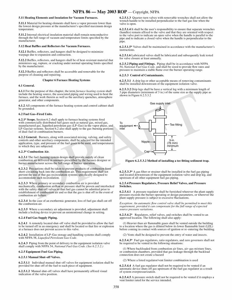
358
NFPA 86 — May 2003 ROP — Copyright, NFPA
DRAFT
5.11 Heating Elements and Insulation for Vacuum Furnaces.
5.11.1 Material for heating elements shall have a vapor pressure lower than the lowest design pressure at the manufacturer’s specified maximum design temperature.
5.11.2 Internal electrical insulation material shall remain nonconductive through the full range of vacuum and temperature limits specified by the manufacturer.
5.12 Heat Baffles and Reflectors for Vacuum Furnaces.
5.12.1 Baffles, reflectors, and hangers shall be designed to minimize warpage due to expansion and contraction.
5.12.2 Baffles, reflectors, and hangers shall be of heat-resistant material that minimizes sag, rupture, or cracking under normal operating limits specified by the manufacturer.
5.12.3 Baffles and reflectors shall be accessible and removable for the purpose of cleaning and repairing.
Chapter 6 Furnace Heating Systems
6.1 General.
6.1.1 For the purpose of this chapter, the term furnace heating system shall include the heating source, the associated piping and wiring used to heat the furnace, and the work therein as well as the auxiliary quenches, atmosphere generator, and other components.
6.1.2 All components of the furnace heating system and control cabinet shall be grounded.
6.2 Fuel Gas–Fired Units.
6.2.1* Scope. Section 6.2 shall apply to furnace heating systems fired with commercially distributed fuel gases such as natural gas, mixed gas, manufactured gas, liquefied petroleum gas (LP-Gas) in the vapor phase, and LP-Gas/air systems. Section 6.2 also shall apply to the gas-burning portions of dual-fuel or combination burners.
6.2.2 General. Burners, along with associated mixing, valving, and safety controls and other auxiliary components, shall be selected for the intended application, type, and pressure of the fuel gases to be used, and temperatures to which they are subjected.
6.2.3* Combustion Air.
6.2.3.1 The fuel-burning system design shall provide supply of clean combustion air delivered in amounts prescribed by the furnace designer or burner manufacturer across the full range of burner operation.
6.2.3.2 Precautions shall be taken to prevent products of combustion from short-circuiting back into the combustion air. This requirement shall not prevent the use of flue gas recirculation systems specifically designed to accommodate such recirculation.
6.2.3.3 Where primary or secondary combustion air is provided mechanically, combustion airflow or pressure shall be proven and interlocked with the safety shut-off valves so that fuel gas cannot be admitted prior to establishment of combustion air and so that the gas is shut off in the event of combustion air failure.
6.2.3.4 In the case of an exothermic generator, loss of fuel gas shall cut off the combustion air.
6.2.3.5 Where a secondary air adjustment is provided, adjustment shall include a locking device to prevent an unintentional change in setting.
6.2.4 Fuel Gas Supply Piping.
6.2.4.1 A remotely located shut-off valve shall be provided to allow the fuel to be turned off in an emergency and shall be located so that fire or explosion at a furnace does not prevent access to this valve.
6.2.4.2 Installation of LP-Gas storage and handling systems shall comply with NFPA 58, Liquefied Petroleum Gas Code.
6.2.4.3 Piping from the point of delivery to the equipment isolation valve shall comply with NFPA 54, National Fuel Gas Code. (See 6.2.5.2.)
6.2.5 Equipment Fuel Gas Piping.
6.2.5.1 Manual Shut-off Valves.
6.2.5.1.1 Individual manual shut-off valves for equipment isolation shall be provided for shut-off of the fuel to each piece of equipment.
6.2.5.1.2 Manual shut-off valves shall have permanently affixed visual indication of the valve position.
6.2.5.1.3 Quarter-turn valves with removable wrenches shall not allow the wrench handle to be installed perpendicular to the fuel gas line when the valve is open.
6.2.5.1.4 It shall be the user’s responsibility to ensure that separate wrenches (handles) remain affixed to the valve and that they are oriented with respect to the valve port to indicate an open valve when the handle is parallel to the pipe and to indicate a closed valve when the handle is perpendicular to the pipe.
6.2.5.1.5* Valves shall be maintained in accordance with the manufacturer’s instructions.
6.2.5.1.6 Lubricated valves shall be lubricated and subsequently leak tested for valve closure at least annually.
6.2.5.2 Piping and Fittings. Piping shall be in accordance with NFPA 54, National Fuel Gas Code, and shall be sized to provide flow rates and pressure to maintain a stable flame over the burner operating range.
6.2.5.3 Control of Contaminants.
6.2.5.3.1 A drip leg or other acceptable means of removing contaminants shall be installed downstream of the equipment isolation valve.
6.2.5.3.2 Drip legs shall be have a vertical leg with a minimum length of 3 pipe diameters (minimum of 3 in.) of the same size as the supply pipe as shown in Figure 6.2.5.3.2
����������������������
���
������
������������������
����������������
�����������
Figure 6.2.5.3.2 Method of installing a tee fitting sediment trap.
6.2.5.3.3* A gas filter or strainer shall be installed in the fuel gas piping and located downstream of the equipment isolation valve and drip leg, and upstream of all other equipment fuel gas piping.
6.2.5.4 Pressure Regulators, Pressure Relief Valves, and Pressure Switches.
6.2.5.4.1 A pressure regulator shall be furnished wherever the plant supply pressure exceeds the burner operating or design parameters, or wherever the plant supply pressure is subject to excessive fluctuations.
Exception: An automatic flow control valve shall be permitted to meet this requirement, provided it can compensate for the full range of expected source pressure variations.
6.2.5.4.2* Regulators, relief valves, and switches shall be vented to an approved location. The following shall also apply:
(1) Heavier than air flammable gases shall be vented outside the building to a location where the gas is diluted below its lower flammable limit (LEL) before coming in contact with sources of ignition or re-entering the building.
(2) Vents shall be designed to prevent the entry of water and insects.
6.2.5.4.3* Fuel gas regulators, ratio regulators, and zero governors shall not be required to be vented in the following situations:
(1) Where backloaded from combustion air lines, air–gas mixture lines, or combustion chambers, provided that gas leakage through the backload connection does not create a hazard
(2) Where a listed regulator/vent limiter combination is used
6.2.5.4.4 A fuel gas regulator shall not be required to be vented if an automatic device shuts off gas upstream of the fuel gas regulator as a result of system overpressurization.
6.2.5.4.5 A pressure switch shall not be required to be vented if it employs a vent limiter rated for the service intended.
359
NFPA 86 — May 2003 ROP — Copyright, NFPA
DRAFT
6.2.5.4.6 Fuel gas regulators and zero governors shall not be backloaded from oxygen or oxygen-enriched air lines.
6.2.5.4.7 Vent lines from multiple furnaces shall not be manifolded together.
6.2.5.4.8 Vent lines from multiple regulators and switches of a single furnace, where manifolded together, shall be piped in such a manner that diaphragm rupture of one vent line does not backload the others. The size of the vent manifold shall be not less than the area of the largest vent line plus 50 percent of the additional vent line area.
6.2.6 Flow Control Valves. Where the minimum or the maximum flow of combustion air or the fuel gas is critical to the operation of the burner, flow valves shall be equipped with limiting means and with a locking device to prevent an unintentional change in the setting.
6.2.7 Air–Fuel Gas Mixers.
6.2.7.1* General. Paragraph 6.2.7 shall apply only to mixtures of fuel gas with air and not to mixtures of fuel gas with oxygen or oxygen-enriched air. Oxygen shall not be introduced into air–fuel gas mixture piping, fuel gas mixing machines, or air–fuel gas mixers.
6.2.7.2 Proportional Mixing.
6.2.7.2.1 Piping shall be designed to provide a uniform mixture flow of proper pressure and velocity as needed for stable burner operation.
6.2.7.2.2 Valves or other obstructions shall not be installed between a proportional mixer and burners. Fixed orifices shall be permitted for purposes of balancing.
6.2.7.2.3 Any field-adjustable device built into a proportional mixer (e.g., gas orifice, air orifice, ratio valve) shall be arranged with locking device to prevent unintentional changes in the setting.
6.2.7.2.4 Where a mixing blower is used, an approved safety shut-off valve shall be installed in the fuel gas supply connection that shuts off the fuel gas supply automatically when the blower is not in operation and in the event of a fuel gas supply failure.
6.2.7.2.5 Mixing blowers shall not be used with fuel gases containing more than 10 percent free hydrogen (H
2).
6.2.7.2.6 Mixing blowers having a static delivery pressure of more than 10 in. w.c. (2.49 kPa) shall be considered mixing machines.
6.2.7.3 Mixing Machines.
6.2.7.3.1* Automatic fire checks shall be provided in piping systems that distribute flammable air–fuel gas mixtures from a mixing machine. The automatic fire check shall be installed as close as practical to the burner inlet(s), and the manufacturer’s installation guidelines shall be followed.
6.2.7.3.2 A separate, manually operated gas valve shall be provided at each automatic fire check for shutting off the flow of air–fuel mixture through the fire check after a flashback has occurred. The valves shall be located upstream as close as practicable to the inlets of the automatic fire checks.
CAUTION:
These valves shall not be reopened after a flashback has occurred until the fire check has cooled sufficiently to prevent reignition of the flammable mixture and has been properly reset.
6.2.7.3.3* A backfire arrester with a safety blowout device shall be provided near the outlet of each mixing machine that produces a flammable air–fuel gas mixture. The manufacturer’s installation guidelines shall be followed.
6.2.7.3.4 A listed safety shut-off valve shall be installed in the fuel gas supply connection of any mixing machine. This valve shall be arranged to shut off the fuel gas supply automatically when the mixing machine is not in operation or in the event of an air or fuel gas supply failure.
Exception: Where listed safety shut-off valves are not available for the service intended, the selected device shall require approval by the authority having jurisdiction.
6.2.8 Fuel Gas Burners.
6.2.8.1 All burners shall maintain the stability of the designed flame shape, without flashback or blow-off, over the entire range of turndown that is encountered during operation where supplied with combustion air (oxygen-enriched air or oxygen) and the designed fuels in the designed proportions and in the designed pressure ranges. Burners shall only be used with the fuels for which they are designed.
6.2.8.2 All pressures required for operation of the combustion system shall be maintained within the ranges throughout the firing cycle.
6.2.8.3 Burners shall have the ignition source sized and located in a position that provides ignition of the pilot or main flame within the design trial-for-ignition period.
6.2.8.4 For burners that cannot be ignited at all firing rates, provision shall be made to adjust the burner firing rate during light-off to a level that ensures ignition of the main flame without flashback or blow-off (proved low-fire start interlock).
6.2.8.5* Radiant tubes that are claimed to be explosion resistant within the use of this standard shall be validated by a test that shall be performed in accordance with the manufacturer’s instructions.
6.2.9 Fuel Ignition.
6.2.9.1* The ignition source (e.g., electric spark, hot wire, pilot burner, handheld torch) shall be applied at the design location with the design intensity to ignite the air–fuel mixture.
6.2.9.2 Fixed ignition sources shall be mounted to prevent unintentional changes in location and in direction with respect to the main flame.
6.2.9.3 Pilot burners shall be considered burners, and all provisions of Section 6.2 shall apply.
6.2.10 Dual-Fuel and Combination Burners. Where fuel gas and fuel oil are to be fired individually (dual-fuel) or simultaneously (combination), the provisions of Sections 6.2, 6.3, and 7.12 shall apply equally to the respective fuels.
6.3 Oil-Fired Units.
6.3.1* Scope. Section 6.3 shall apply to combustion systems for furnaces fired with No. 2, No. 4, No. 5, and No. 6 industrial fuel oils as specified by ASTM D 396, Standard Specifications for Fuel Oils. It shall also apply to the oil-burning portions of dual-fuel and combination burners.
6.3.2 General. Burners, along with associated valving, safety controls, and other auxiliary components, shall be selected for the type and pressure of the fuel oil to be used and for the temperatures to which they are subjected.
6.3.3* Combustion Air.
6.3.3.1 The fuel-burning system design shall provide for a supply of clean combustion air delivered in the amounts prescribed by the furnace designer or burner manufacturer across the full range of burner operation.
6.3.3.2 Precautions shall be taken to prevent products of combustion from short-circuiting back into the combustion air. This requirement shall not prevent the use of flue gas recirculation systems specifically designed to accommodate such recirculation.
6.3.3.3 Where primary or secondary combustion air is provided mechanically, combustion airflow or pressure shall be proven and interlocked with the safety shut-off valves so that oil cannot be admitted prior to establishment of combustion air and so that the oil is shut off in the event of combustion air failure.
6.3.3.4 Where a secondary air adjustment is provided, adjustment shall include a locking device to prevent an unintentional change in setting.
6.3.4 Oil Supply Piping.
6.3.4.1 Storage tanks, their installation, and their supply piping materials shall comply with NFPA 31, Standard for the Installation of Oil-Burning Equipment.
6.3.4.2 A remotely located shut-off valve shall be provided to allow the fuel to be turned off in an emergency and shall be located so that fire or explosion at a furnace does not prevent access to this valve. A positive displacement oil pump shall be permitted to serve as a valve by shutting off its power.
6.3.4.3 Where a shut-off is installed in the discharge line of an oil pump that is not an integral part of a burner, a pressure-relief valve shall be connected to the discharge line between the pump and the shut-off valve and arranged to return surplus oil to the supply tank or to bypass it around the pump, unless the pump includes an internal bypass.
6.3.4.4* All air from the supply and return piping shall be purged initially, and air entrainment in the oil shall be minimized.
6.3.4.5 Suction, supply, and return piping shall be sized with respect to oil pump capacity.
6.3.4.6* Wherever a section of oil piping can be shut off at both ends, relief valves or expansion chambers shall be used to release the pressure caused by thermal expansion of the oil.
6.3.5 Equipment Oil Piping.
6.3.5.1 Manual Shut-off Valves.
360
NFPA 86 — May 2003 ROP — Copyright, NFPA
DRAFT
6.3.5.1.1 Individual manual shut-off valves for equipment isolation shall be provided for shut-off of the fuel to each piece of equipment.
6.3.5.1.2 Manual shut-off valves shall be installed to avoid oil spillage during servicing of supply piping and associated components.
6.3.5.1.3 Manual shut-off valves shall display a permanently affixed visual indication of the valve position.
6.3.5.1.4 Quarter-turn valves with removable wrenches shall not allow the wrench handle to be installed perpendicular to the fuel oil line when the valve is open.
6.3.5.1.5 The user shall keep separate wrenches (handles) affixed to valves and keep the wrenches oriented with respect to the valve port to indicate an open valve when the handle is parallel to the pipe and to indicate a closed valve when the handle is perpendicular to the pipe.
6.3.5.1.6* Valves shall be maintained in accordance with the manufacturer’s instructions.
6.3.5.1.7 Lubricated valves shall be lubricated and subsequently leak tested for valve closure at least annually.
6.3.5.2 Piping and Fittings. Piping and fittings shall be in accordance with NFPA 31, Standard for the Installation of Oil-Burning Equipment, and shall be sized to provide flow rates and pressure so as to maintain a stable flame over the burner operating range.
6.3.5.3* Oil Filters and Strainers. An oil filter or strainer shall be installed in the oil piping to protect the downstream components. The filter shall be selected to filter particles larger than the most critical clearance in the system and for the maximum operating pressure and temperature anticipated.
6.3.5.4 Pressure Regulation. Where the oil pressure exceeds that required for burner operation or where the oil pressure is subject to excessive fluctuations, either a pressure regulator or an automatic flow control valve that can compensate for the full range of expected source pressure variations shall be installed.
6.3.5.5* Pressure Gauges. Pressure gauges shall be isolated or protected from pulsation damage during operation of the burner system.
6.3.6 Flow Control Valves. Where the minimum or the maximum flow of combustion air or the fuel oil is critical to the operation of the burner, flow valves shall be equipped with a limiting means and with a locking device to prevent an unintentional change in the setting.
6.3.7 Oil Atomization.
6.3.7.1* Oil shall be atomized to droplet size as required for combustion throughout the firing range.
6.3.7.2 The atomizing device shall be accessible for inspection, cleaning, repair, replacement, and other maintenance as required.
6.3.8 Oil Burners.
6.3.8.1 All burners shall maintain the stability of the designed flame shape over the entire range of turndown that is encountered during operation where supplied with combustion air (oxygen-enriched air or oxygen) and the designed fuels in the designed proportions and in the designed pressure ranges.
6.3.8.2 All pressures required for the operation of the combustion system shall be maintained within the design ranges throughout the firing cycle.
6.3.8.3 The burner shall be supplied with fuel oil of the grade for which they have been designed and with fuel oil that has been preconditioned, where necessary, to the viscosity required by the burner design.
6.3.8.4 Burners shall have the ignition source sized and located in a position that provides ignition of the pilot or main flame within the design trial-for-ignition period.
6.3.8.4.1 Self-piloted burners shall have a transition from pilot flame to main flame.
6.3.8.4.2 For burners that cannot be ignited at all firing rates, provision shall be made to reduce the burner firing rates during light-off to a lower level, which ensures ignition of the main flame without flashback or blow-off (forced low-fire start).
6.3.8.5 If purging of oil passages upon termination of a firing cycle is required, it shall be done prior to shutdown with the initial ignition source present and with all associated fans and blowers in operation.
6.3.9 Fuel Ignition.
6.3.9.1* The ignition source (e.g., electric spark, hot wire, pilot burner, hand-held torch) shall be applied at the design location with the design intensity to ignite the air–fuel mixture.
6.3.9.2 Fixed ignition sources shall be mounted so as to prevent unintentional changes in location and in direction with respect to the main flame.
6.3.9.3 Pilot burners shall be considered burners, and all provisions of Section 6.2 shall apply.
6.3.10 Dual-Fuel and Combination Burners. Where fuel gas and fuel oil are fired individually (dual-fuel) or simultaneously (combination), the provisions of Sections 6.2, 6.3, and 7.12 shall apply equally to the respective fuels.
6.4 Oxygen-Enhanced Fuel-Fired Units.
6.4.1* Scope. Section 6.4 shall apply to combustion systems using oxygen (oxy-fuel) or oxygen-enriched air with gas or liquid fuels. The requirements shall be in addition to those in Sections 6.2 and 6.3 and Chapter 7.
6.4.2 Combustion Systems Utilizing Oxygen.
6.4.2.1 Oxygen storage and delivery systems shall comply with NFPA 50, Standard for Bulk Oxygen Systems at Consumer Sites.
6.4.2.2 Oxygen shall not be introduced into inlet or discharge piping of air compressors or blowers that are internally lubricated with petroleum oils, greases, or other combustible substances.
6.4.3 Oxygen Piping and Components.
6.4.3.1 Design, materials of construction, installation, and tests of oxygen piping shall comply with the applicable sections of ASME B31.3, Process Piping.
6.4.3.2* Materials and construction methods used in the installation of the oxygen piping and components shall be compatible with oxygen.
6.4.3.3* Piping and components that come in contact with oxygen shall be cleaned prior to admitting gas.
6.4.3.4* Air introduced into oxygen passages in burners, such as cooling air, shall be free of particulate matter, oil, grease, and other combustible materials.
6.4.3.5 A remotely located shut-off valve shall be provided to allow the oxygen to be turned off in an emergency and shall be located so that fire or explosion at a furnace does not prevent access to this valve.
6.4.3.6 Oxygen from pressure-relief devices and purge outlets shall not be released into pipes or manifolds where it can mix with fuel.
6.4.3.7* Oxygen from pressure-relief devices and purge outlets shall be vented to an approved location. Vents shall be designed to prevent the entry of water and insects.
6.4.3.8 Means shall be provided to prevent oxygen, fuel, or air to intermix in burner supply lines due to valve leakage, burner plugging, or other system malfunctions.
6.4.3.9* Oxygen piping and components shall be inspected and maintained.
6.4.3.10 If glass tube flowmeters are used in oxygen service, safeguards against personnel injury from possible rupture shall be provided.
6.4.3.11* The piping fed from a cryogenic supply source shall be protected from excessive cooling by means of an automatic low-temperature shut-off device.
6.4.3.12 Piping and controls downstream of an oxygen pressure-reducing regulator shall be able to withstand the maximum potential upstream pressure or shall be protected from overpressurization by means of a pressure-relief device.
6.4.4 Oxygen Flow Control Valves.
6.4.4.1 Where the minimum or the maximum flow of oxygen or oxygen-enriched air is critical to the operation of the burner, flow control valves shall be equipped with limiting means and locking device to prevent an unintentional change in the setting.
6.4.4.2 Where the source oxygen pressure exceeds that required for burner operation or where the source pressure is subject to excessive fluctuations, either an oxygen pressure regulator or an automatic flow control valve that can compensate for the full range of expected source pressure variations and complies with 6.4.4.1 shall be installed.
6.4.5 Oxygen-Enriched Combustion Air.
6.4.5.1 Filters shall be installed in the air blower intake to minimize contamination of the oxygen-enriched air piping.
6.4.5.2* Devices, such as diffusers, used to disperse oxygen into an airstream shall be designed to prevent jet impingement of oxygen onto interior surfaces of the air piping.
361
NFPA 86 — May 2003 ROP — Copyright, NFPA
DRAFT
6.4.5.3 Oxygen-enriched combustion air shall not be introduced into a burner before the oxygen has been uniformly mixed into the airstream.
6.4.5.4 Branching of the enriched-air piping shall not be permitted before a uniform mixture of oxygen and air has been attained.
6.5 Flue Product Venting.
6.5.1 A means shall be provided to ensure ventilation of the products of combustion from fuel-fired equipment.
6.5.2 Collecting and venting systems for radiant tube-type heating systems shall be of a capacity to prevent an explosion or fire hazard due to the flow of unburned fuel through the radiant tubes. The system shall be capable of dilution of the rated maximum input capacity of the system to a noncombustible state. A radiant tube-type heating system provided with two safety shut-off valves interlocked with combustion safeguards shall be exempt from this requirement.
6.6 Electrically Heated Units.
6.6.1 Scope. Section 6.6 shall apply to all types of heating systems where electrical energy is used as the source of heat.
6.6.2 Safety Equipment. Safety equipment including airflow interlocks, time relays, and temperature switches shall be in accordance with Chapter 7.
6.6.3* Electrical Installation. All parts of the electrical installation shall be in accordance with NFPA 70, National Electrical Code.
6.6.4 Resistance Heating Systems.
6.6.4.1 The provisions of 6.6.4 shall apply to resistance heating systems, including infrared lamps, such as quartz, ceramic, and tubular glass types.
6.6.4.2 Construction.
6.6.4.2.1 The heater housing shall be constructed so as to provide access to heating elements and wiring.
6.6.4.2.2 Heating elements and insulators shall be supported securely or fastened so that they do not become easily dislodged from their intended location.
6.6.4.2.3 Heating elements that are electrically insulated from and supported by a metallic frame shall have the frame electrically grounded.
6.6.4.2.4 Open-type resistor heating elements shall be supported by electrically insulated hangers and shall be secured to prevent the effects of motion induced by thermal stress, which could result in adjacent segments of the elements touching one another, or the effects of touching a grounded surface.
6.6.4.2.5 External parts of furnace heaters that are energized at voltages that could be hazardous as specified in NFPA 70, National Electrical Code, shall be guarded.
6.6.4.3 Heater Locations. Heaters shall not be located directly under the product being heated where combustible materials can drop and accumulate.
Exception: Heating elements shall be allowed to be located in areas where combustible materials can drop and accumulate if the oxygen concentration is insufficient to support combustion.
6.6.5 Induction and Dielectric Heating Systems.
6.6.5.1 Induction and dielectric heating systems shall be designed and installed in accordance with NFPA 70, National Electrical Code.
6.6.5.2 Construction.
6.6.5.2.1* Combustible electrical insulation shall be reduced to a minimum.
6.6.5.2.2 Protection shall be installed to prevent overheating of any part of the equipment in accordance with NFPA 70, National Electrical Code.
6.6.5.2.3 Where water-cooling is used for transformers, capacitors, electronic tubes, spark gaps, or high-frequency conductors, cooling coils and connections shall be arranged so that leakage or condensation does not damage the electrical equipment. The cooling-water supply shall be interlocked with the power supply so that loss of water cuts off the power supply. Consideration shall be given to providing individual pressure flow interlocks for parallel waterflow paths.
6.6.5.2.4 Where forced ventilation by motor-driven fans is necessary, the air supply shall be interlocked with the power supply. An air filter shall be provided at the air intake.
6.6.5.2.5 The conveyor motor and the power supply of dielectric heaters of the conveyor type used to heat combustible materials shall be interlocked to prevent overheating of the material being treated.
6.6.5.2.6 Dielectric heaters used for treating highly combustible materials shall be designed to prevent a disruptive discharge between the electrodes.
6.7 Fluid-Heated Systems.
6.7.1* Scope. Section 6.7 shall apply to all types of systems where water, steam, or other heat transfer fluids are the source of heat through the use of heat exchangers. Section 6.7 covers the heat transfer fluid system between the oven supply and return isolation valves for the oven being served.
6.7.2 General.
6.7.2.1* Piping and fittings shall be in accordance with the ASME B31.1, Power Piping.
6.7.2.2 Piping containing combustible heat transfer fluid that is insulated shall use closed-cell, nonabsorptive insulation. Fibrous or open-cell insulation shall not be permitted.
6.7.2.3* Oven isolation valves shall be installed in the fluid supply and return lines. If a combustible heat transfer fluid is used, the oven isolation valves shall be installed within 5 ft (1.5 m) of the oven.
6.7.2.4 Enclosures or ductwork for heat exchanger coils shall be of noncombustible construction with suitable access openings provided for maintenance and cleaning.
6.7.2.5 Heat exchangers or steam coils shall not be located on the floor of an oven or in any position where paint drippage or combustible material can accumulate on the coils.
6.7.3 Safety Devices.
6.7.3.1 System equipment shall be operated within the temperature and pressure limits specified by the supplier or manufacturer of the heat transfer medium and by the manufacturer of the equipment.
6.7.3.2 If the oven atmosphere is recirculated over the heat exchanger coils, a noncombustible filtration system shall be used if combustible particulates can deposit on the heat exchanger surface. The filtration system and heat exchanger shall be cleaned on a regular schedule.
6.8 Heating Elements for Vacuum Furnaces.
6.8.1* The design of heating elements can take several forms, such as rods, bars, sheets, or cloth, but shall be limited to materials that do not vaporize under minimum vacuum and maximum temperature.
6.8.2 Electrical heating equipment in a vacuum furnace shall not be operable until a vacuum level established as part of the furnace design has been attained inside the furnace chamber to provide protection for the furnace elements, radiant shields, or insulation.
6.8.3* Heating element support hangers and insulators shall be of compatible materials to provide electrical insulation and nonreacting materials at specified vacuum levels and temperatures.
6.8.4 Heating element connections shall be designed to minimize arcing and disassembly problems.
6.8.5 The heating element power terminal and vessel feed-through shall be designed and installed for vacuum integrity and to withstand heating effects.
6.8.6 Power terminal connection points to power supply cables shall be covered or housed to prevent high-current electrical hazard to personnel.
6.9* Furnace Thermal Insulation and Heat Shields for Vacuum Furnaces.
6.9.1* Insulation shall not break down at maximum specified vacuum levels and temperatures.
6.9.2* Heat shield material shall comply with temperature and vacuum requirements.
6.9.3* Insulation shall be installed so as to prevent it from breaking up and becoming airborne.
Chapter 7 Safety Equipment and Application
7.1 Scope.
7.1.1 Chapter 7 shall apply to safety equipment and its application to furnace heating and ventilation systems. Section 7.3 shall apply to all safety controls included in this standard.
7.1.2* For the purpose of this chapter, the term furnace heating system shall include the heating source, associated piping and wiring used to heat the furnace, auxiliary quenches, and the work therein.
7.2 General.
362
NFPA 86 — May 2003 ROP — Copyright, NFPA
DRAFT
7.2.1 All safety devices shall be listed for the service intended. Safety devices shall be applied and installed in accordance with this standard and the manufacturer’s instructions.
Exception: Where listed devices are not available for the service intended, the selected device shall require approval by the authority having jurisdiction.
7.2.2 Electric relays and safety shut-off valves shall not be used as substitutes for electrical disconnects and manual shut-off valves.
7.2.3 Purge, ignition trials, and other burner safety sequencing shall be performed only using devices listed for such service.
7.2.4 A shutdown of the heating system by any safety feature or safety device shall require manual intervention of an operator for re-establishment of the normal operation of the system.
7.2.5 Regularly scheduled inspection, testing, and maintenance of all safety devices shall be performed. (See Chapter 14, Inspection, Testing, and Maintenance.)
7.2.5.1 It shall be the responsibility of the equipment manufacturer to provide operating instructions that cover start-up, shutdown, emergencies, and procedures for inspection, testing, and maintenance.
7.2.5.2 It shall be the responsibility of the user to establish, schedule, and enforce the frequency and extent of the inspection, testing, and maintenance program, as well as the corrective action to be taken. Documented safety inspections and testing shall be performed at least annually.
7.2.6 Safety devices shall be installed, used, and maintained in accordance with the manufacturer’s instructions.
7.2.7* All combustion safety circuitry contacts for required safety interlocks and excess temperature limit controllers shall be arranged in series ahead of the safety shut-off valve holding medium.
Exception No. 1: Devices specifically listed for combustion safety service shall be permitted to be used in accordance with the listing requirements and the manufacturer’s instructions.
Exception No. 2: Interposing relays shall be permitted where the conditions of (1), (2),(3) and (4) are met:
(1) Required connected load exceeds the rating of available safety interlock devices or where necessary to perform required safety logic functions
(2) Interposing relay is configured to revert to a safe condition upon loss of power
(3) Each interposing relay serves no more than one safety interlock device
(4) The interposing relay is listed for combustion safety service or for general purpose applications
7.2.8 Safety devices shall be located or guarded to protect them from physical damage.
7.2.9 Safety devices shall not be removed or rendered ineffective.
7.2.10 Safety devices shall not be bypassed electrically or mechanically. This requirement shall not prohibit safety device testing and maintenance in accordance with 7.2.5. When a system includes a “built-in” test mechanism that bypasses any safety device, it shall be interlocked to prevent operation of the system while the device is in the test mode, unless listed for that purpose.
7.2.11* Electrical power for safety control circuits shall be single-phase, one-side grounded, with all breaking contacts in the “hot” ungrounded, fuse-protected, or circuit breaker-protected line, and shall not exceed 120-volt potential.
7.3 Programmable Controllers for Safety Service.
7.3.1 General.
7.3.1.1 The supplier of the application software for the programmable controller shall provide the end user and the authority having jurisdiction with the documentation needed to verify that all related safety devices and safety logic are functional before the programmable controller is placed in operation.
7.3.1.2* In the event of a power failure, the programmable controller (hardware and software) shall not prevent the system from reverting to a safe default condition. A safe condition shall be maintained upon the restoration of power.
7.3.1.3 The control system shall have a separate manual emergency switch, independent of the programmable controller, that initiates a safe shutdown.
CAUTION: For some applications, additional manual action will be required to bring the process to a safe condition.
7.3.1.4 Any changes to hardware or software shall be documented, approved, and maintained in a file on the site.
7.3.1.5* The internal status of the programmable controller shall be monitored. In the event of a programmable controller failure, the system shall annunciate and cause the system to revert to a safe condition.
7.3.1.6* Security measures shall be provided to prevent unauthorized access to the programmable controller or its logic that could result in hazards to personnel or equipment.
7.3.2 Combustion Safety Functions.
7.3.2.1* Programmable controller-based systems specifically listed for combustion safety service shall be permitted where applied in accordance with the listing requirements and the manufacturer’s instructions.
7.3.2.2 A programmable controller not listed for combustion safety service shall be permitted to monitor safety interlocks, or to provide burner control functions, provided that its use complies with both of the following:
(1) The programmable controller shall not interfere with or prevent the operation of the safety interlocks.
(2) Only isolated programmable controller contacts (not directly connected to a power source) shall be permitted to be wired in series with the safety interlocks to permit burner control functions.
7.3.2.3 The requirements of 7.2.3 shall apply to programmable controller-based systems.
7.3.3 Hardware.
7.3.3.1* A failure of programmable controller hardware shall cause the system to revert to a safe default condition.
7.3.3.2 A programmable controller shall be provided with a watchdog timer external to the CPU and memory. Failures detected by the watchdog timer shall cause the system to revert to a safe default condition.
7.3.3.3 System operation shall be tested and verified for compliance with the original design criteria whenever the programmable controller is replaced, repaired, or updated.
7.3.4 Software.
7.3.4.1 Whenever application software that contains safety logic or detection logic is modified, system operation shall be verified for compliance to the original design criteria.
7.3.4.2 The software for the programmable controller shall reside in memory that retains information on loss of system power.
7.3.4.3 Application software that contains safety logic shall be separated from all other programming. Application software that interacts with safety logic or detection logic for input/output devices shall be separated from all other programming.
7.4 Safety Control Application for Fuel-Fired Heating Systems.
7.4.1 Preignition (Prepurge, Purging Cycle).
7.4.1.1* Prior to each furnace heating system start-up, provision shall be made for the removal of all flammable vapors and gases that might have entered the heating chambers during the shutdown period.
7.4.1.2 A timed preignition purge shall be provided. At least 4 standard cubic feet (scf) of fresh air or inert gas per cubic foot (4 m3/m3) of heating chamber volume shall be introduced during the purging cycle.
7.4.1.2.1 To begin the timed preignition purge interval, both of the following conditions shall be satisfied:
(1) The minimum required preignition airflow shall be proven (see Sections 7.5 and 7.6 for proof of airflow requirements).
(2) The safety shut-off valve(s) shall be proved closed (see 7.7.2.2 and 7.7.3.3 for proved closed requirements).
7.4.1.2.2 The minimum required preignition purge airflow shall be proven and maintained throughout the timed preignition purge interval.
7.4.1.2.3 Failure to maintain the minimum required preignition purge airflow shall stop the preignition purge and reset the purge timer.
7.4.1.3 A furnace heating system, either alone or as part of multiple furnaces feeding into one fume incinerator, shall not be purged into an operating incinerator.
Exception: A furnace heating system shall be permitted to be purged into an operating incinerator if it can be demonstrated that the flammable vapor concentration entering the fume incinerator cannot exceed 50 percent of the LEL.
363
NFPA 86 — May 2003 ROP — Copyright, NFPA
DRAFT
7.4.1.4 Preignition purging of radiant tube-type heating systems shall be provided.
Exception: Preignition purging of radiant tube-type heating systems shall not be required where the systems are arranged and designed such that the conditions of (1) or (2) are satisfied.
(1) The tubes are of metal construction and open at one or both ends with heat recovery systems, if used, that are of explosion-resistant construction.
(2) The entire radiant tube heating system, including any associated heat recovery system, is of explosion-resistant construction.
7.4.1.5 Prior to the reignition of a burner after a burner shutdown or flame failure, a preignition purge shall be accomplished.
Exception: Repeating the preignition purge shall not be required where the conditions of (1), (2), or (3) are satisfied.
(1) The heating chamber temperature exceeds 1400°F (760°C).
(2) For any fuel-fired system, all of the following conditions are satisfied:
(a) Each burner and pilot is supervised by a combustion safeguard in accordance with Section 7.9.
(b) Each burner system is equipped with safety shut-off valves in accordance with Section 7.7.
(c) At least one burner remains operating in the common combustion chamber of the burner to be reignited.
(3) All of the following conditions are satisfied (does not apply to fuel oil systems):
(a) Each burner and pilot is supervised by a combustion safeguard in accordance with Section 7.9.
(b) Each burner system is equipped with gas safety shut-off valves in accordance with Section 7.7.
(c) It can be demonstrated that the combustible concentration in the heating chamber cannot exceed 25 percent of the LEL.
CAUTION: Repeated ignition attempts can result in a combustible concentration greater than 25 percent of the LEL. Liquid fuels can accumulate causing additional fire hazards.
7.4.2* Trial-for-Ignition Period.
7.4.2.1 The trial-for-ignition period of the pilot burner shall not exceed 15 seconds.
7.4.2.2 The trial-for-ignition period of the main gas burner shall not exceed 15 seconds.
Exception: The trial-for-ignition period of the main gas burner shall be permitted to exceed 15 seconds if both of the following conditions are satisfied:
(1) A written request for an extension of trial for ignition is approved by the authority having jurisdiction.
(2) It is determined that 25 percent of the LEL cannot be exceeded in the extended time.
7.4.2.3 The trial-for-ignition period of the main oil burner shall not exceed 15 seconds.
7.5 Ventilation Safety Devices.
7.5.1 Wherever a fan is essential to the operation of the oven or allied equipment, fan operation shall be proven and interlocked into the safety circuitry.
7.5.1.1 Electrical interlocks and flow switches shall be arranged in the safety control circuit so that loss of ventilation or airflow immediately shuts down the heating system of the affected section, or, if necessary, loss of ventilation shall shut down the entire heating system as well as the conveyor.
7.5.1.2 Air pressure switches shall not be used to prove airflow where dampers downstream of the pressure switch can be closed to the point of reducing flow to an unsafe operating level.
7.5.1.3 Air suction switches shall not be used to prove airflow where dampers upstream of the pressure switch can be closed to the point of reducing flow to an unsafe operating level.
7.5.1.4 Switches used to prove airflow on systems where the air is contaminated with any substance that might condense or otherwise create a deposit shall be selected and installed to prevent interference with the performance of the switch.
7.5.2 Dampers capable of being adjusted to a position that can result in an unsafe condition shall be equipped with mechanical stops, cut-away dampers, or limit switches interlocked into the safety circuitry to ensure that the oven will not operate when the dampers are in an unsafe position.
7.6 Combustion Air Safety Devices.
7.6.1 Where the air from the exhaust or recirculating fans is required for combustion of the fuel, airflow shall be proven prior to an ignition attempt. Reduction of airflows to an unsafe level shall result in closure of the safety shut-off valves.
7.6.2 Where a combustion air blower is used, the minimum combustion air flow or source pressure needed for burner operation shall be proven prior to each attempt at ignition.
7.6.3 Motor starters on equipment required for the combustion of the fuel shall be interlocked into the combustion safety circuitry.
7.6.4* Combustion air minimum pressure or flow shall be interlocked into combustion safety circuitry by any of the following methods:
(1) A low pressure switch that senses and monitors the combustion air source pressure
(2) A differential pressure switch sensing the differential pressure across a fixed orifice in the combustion air system
(3) An airflow switch
7.6.5 Wherever it is possible for combustion air pressure to exceed a maximum safe operating pressure, as might occur where compressed air is utilized, a high pressure switch interlocked into the combustion safety circuitry shall be used.
7.7 Safety Shut-off Valves (Fuel Gas or Oil).
7.7.1 General.
7.7.1.1 Safety shut-off valves shall be utilized as a key safety control to protect against explosions and fires.
7.7.1.2* Each safety shut-off valve required in 7.7.2.1 and 7.7.3.1 shall automatically shut off the fuel to the burner system after interruption of the holding medium (such as electric current or fluid pressure) by any one of the interlocking safety devices, combustion safeguards, or operating controls.
Exception: For fuel gas or oil systems, where multiple burners or pilots operate as a burner system firing into a common heating chamber, the loss of flame signal at one or more burners shall be permitted to shut off those burner(s) by closing a single safety shut-off valve, provided the following conditions in both (1) and (2) are satisfied.
(1) For the individual burner safety shut-off valve one of the two following conditions shall be met:
(a) For fuel gas systems only, it is demonstrated based on available airflow that failure of the valve to close will result in a fuel concentration not greater than 25 percent of the LEL.
(b) The safety shut-off valve has proof of closure acceptable to the authority having jurisdiction.
(2) The safety shut-off valve upstream of the individual burner safety shut-off valves shall close for any of the following conditions:
(a) Activation of any operating control or interlocking safety device other than the combustion safeguard.
(b) For fuel gas systems only, when the individual burner valves do not have proof of closure as described in (1) and the number of failed burners are capable of exceeding 25 percent of the LEL if their single safety shut-off valves should fail in the open position
(c) When individual burner valves have proof of closure as described in 1(a) and verification that the individual burner safety shut-off valve has closed following loss of flame signal at the burner is not present.
(d) For fuel gas systems only, loss of flame signal at all burners in the burner system or at a number of burners in the burner system that will result in a fuel concentration greater than 25 percent of the LEL.
7.7.1.3 Safety shut-off valves shall not be used as modulating control valves. The use of listed safety shut-off valves designed as both a safety shut-off valve and a modulating valve, and tested for concurrent use, shall be permitted.
7.7.1.4 Valve components shall be of a material suitable for the fuel handled and for ambient conditions.
364
NFPA 86 — May 2003 ROP — Copyright, NFPA
DRAFT
7.7.1.5 Safety shut-off valves in systems containing particulate matter or highly corrosive fuel gas shall be operated regularly in accordance with the manufacturer’s instructions to maintain the safety shut-off valves in operating condition.
7.7.1.6 Valves shall not be subjected to supply pressures in excess of the manufacturer’s ratings.
7.7.1.7* Valves shall be selected to withstand the maximum anticipated back pressure of the system.
7.7.1.8* If the inlet pressure to a fuel pressure regulator exceeds the pressure rating of any downstream component, over-pressure protection shall be provided.
7.7.1.9 Local visual position indication shall be provided at each safety shut-off valve to burners or pilots in excess of 150,000 Btu/hr (44 kW). This indication shall directly indicate the physical position, closed and open, of the valve. Where lights are used for position indication, the absence of light shall not be used to indicate open or closed position. Indirect indication of valve position, such as by monitoring operator current voltage or pressure, shall not be permitted.
7.7.2* Fuel Gas Safety Shut-off Valves.
7.7.2.1 Each main and pilot fuel gas burner system shall be separately equipped with two safety shut-off valves piped in series. A single safety shut-off valve shall be permitted on a radiant tube–fired burner system where the following conditions of (1) or (2) are satisfied:
(1) The tubes are of metal construction and open at one or both ends with heat recovery systems, if used, that are of explosion-resistant construction.
(2) The entire radiant tube heating system, including any associated heat recovery system, is of explosion-resistant construction.
7.7.2.2 Where the main or pilot fuel gas burner system capacity exceeds 400,000 Btu/hr (117 kW), at least one of the safety shut-off valves between each burner and the fuel supply shall be proved closed and interlocked with the preignition purge interval. (See 7.4.1.2.1.)
7.7.2.2.1 Proved Closed shall be accomplished by any of the following means:
(1) A proof of closure switch
(2) A valve proving system
7.7.2.2.2 Auxiliary and closed position indicator switches shall not satisfy the proved closed requirement.
7.7.2.3 A permanent and ready means for testing of valve seat leakage of all fuel gas safety shut-off valves shall be provided.
7.7.2.4* Valve seat leakage test of safety shut-off valves and valve proving systems shall be performed in accordance with the manufacturer’s instructions. Testing frequency shall be at least annually.
7.7.3 Oil Safety Shut-off Valves.
7.7.3.1 Two safety shut-off valves shall be provided under any one of the following conditions:
(1) Where the pressure is greater than 125 psi (862 kPa)
(2) Wherever the fuel oil pump operates without the main oil burner firing, regardless of the pressure
(3) For combination gas and oil burners, where the fuel oil pump operates during the fuel gas burner operation
7.7.3.2 Where none of the conditions of 7.7.3.1(1) through (3) apply, a single safety shut-off valve shall be permitted.
7.7.3.3 Where two safety shut-off valves are required by 7.7.3.1, at least one of the two safety shut-off valves shall be proved closed and interlocked with the preignition purge interval.
7.8 Fuel Pressure Switches (Gas or Oil).
7.8.1 A low pressure switch shall be provided and shall be interlocked into the combustion safety circuitry.
7.8.2 A high fuel pressure switch shall be provided and interlocked into the combustion safety circuitry. The switch shall be located downstream of the final pressure-reducing regulator
7.8.3 Pressure switch settings shall be made in accordance with the operating limits of the burner system.
7.9 Combustion Safeguards (Flame Supervision).
7.9.1 Each burner flame shall be supervised by a combustion safeguard having a maximum flame failure response time of 4 seconds or less, that
performs a safe-start check, and is interlocked into the combustion safety circuitry.
Exception No. 1: The flame supervision shall be permitted to be switched out of the combustion safety circuitry for a furnace zone when that zone temperature is at or above 1400°F (760°C). When the zone temperature drops below 1400°F (760°C), the burner shall be interlocked to allow its operation only if flame supervision has been re-established. A 1400°F (760°C) bypass controller shall be used for this purpose.
Exception No. 2: Combustion safeguards on radiant tube–type heating systems shall not be required where a suitable means of ignition is provided and the systems are arranged and designed such that the following conditions of (1) or (2) are satisfied.
(1) The tubes are of metal construction and open at one or both ends with heat recovery systems, if used, and they are of explosion-resistant construction.
(2) The entire radiant tube heating system, including any associated heat recovery system, is of explosion-resistant construction.
Exception No. 3: Burners without flame supervision shall be permitted, provided these burners are interlocked to prevent their operation when the zone temperature is less than 1400°F (760°C). A 1400°F (760°C) bypass controller shall be used for this purpose.
7.9.2* Flame Supervision.
7.9.2.1 Each pilot and main burner flame shall be supervised independently. One flame sensor shall be permitted to be used to supervise the main burner and pilot flames if an interrupted pilot is used. One flame sensor shall be permitted to be used to supervise self-piloted burners, as defined in Chapter 2.
7.9.2.2* Line burners, pipe burners, and radiant burners, where installed immediately adjacent to one another or connected with flame-propagating devices, shall be considered to be a single burner and shall have at least one flame safeguard installed to sense burner flame at the end of the assembly farthest from the source of ignition.
7.10 Fuel Oil Atomization (Other than Mechanical Atomization).
7.10.1 Adequate pressure of the atomizing medium shall be proven and interlocked into the combustion safety circuitry.
7.10.2 The low pressure switch used to supervise the atomizing medium shall be located downstream from all valves and other obstructions that can shut off flow or cause excessive pressure drop of atomization medium.
7.10.3 Where the atomizing medium requires modulation, an additional low atomizing medium pressure switch shall be provided to meet the requirements of 7.10.1, located upstream of the modulating valve.
7.11* Fuel Oil Temperature Limit Devices. Where equipment is used to regulate fuel oil temperature, fuel oil temperature limit devices shall be provided and interlocked into the combustion safety circuitry if it is possible for the fuel oil temperature to rise above or fall below the temperature range required by the burners.
7.12 Multiple Fuel Systems.
7.12.1 Safety equipment in accordance with the requirements of this standard shall be provided for each fuel used. The fact that oil or gas is considered a standby fuel shall not reduce the safety requirements for that fuel.
7.12.2 Where dual-fuel burners are used, positive provision shall be made to prevent the simultaneous introduction of both fuels. This requirement shall not apply to combination burners.
7.13 Air–Fuel Gas Mixing Machines.
7.13.1 A safety shut-off valve shall be installed in the fuel gas supply connection of any mixing machine.
7.13.2 The safety shut-off valve shall be arranged to shut off the fuel gas supply automatically when the mixing machine is not in operation or in the event of an air or fuel gas supply failure.
7.14 Oxygen Safety Devices.
7.14.1 Two oxygen safety shut-off valves in series shall be provided in the oxygen supply line.
7.14.2 A filter or fine-mesh strainer shall precede the upstream safety shut-off valve.
7.14.3 There shall be a high oxygen flow or pressure limit interlocked into the combustion safety circuitry. The switch shall be located downstream of the final pressure regulator or automatic flow control valve.
365
NFPA 86 — May 2003 ROP — Copyright, NFPA
DRAFT
7.14.4 There shall be a low oxygen flow or pressure limit interlocked into the combustion safety circuitry.
7.14.5 The oxygen safety shut-off valves shall shut automatically after interruption of the holding medium by any one of the interlocking safety devices.
7.14.6 Safety shut-off valves shall not be used as modulating control valves.
Exception: The use of listed safety shut-off valves designed as both a safety shut-off valve and a modulating valve, and tested for concurrent use, shall be permitted.
7.14.7 A permanent and ready means for making tightness checks of all oxygen safety shut-off valves shall be provided.
7.14.8 Local visual position indication shall be provided for each oxygen safety shut-off valve to burners or pilots in excess of 150,000 Btu/hr (44 kW). This indication shall directly indicate the physical position, closed and open, of the valve. Where lights are used for position indication, the absence of light shall not be used to indicate open or closed position. Indirect indication of valve position, such as by monitoring operator current voltage or pressure, shall not be permitted.
7.14.9 Oxygen-Enriched Burners.
7.14.9.1 Where oxygen is added to a combustion air line, an interlock shall be provided to permit oxygen flow only when airflow is proven continuously. Airflow shall be proven in accordance with the requirements of 7.5.5.
7.14.9.2 Upon loss of oxygen flow, the flow of fuel shall be permitted to continue where there is no interruption in the flow of combustion air, provided the control system can revert automatically to a safe air-fuel ratio before a hazard due to a fuel-rich flame is created.
7.14.10 Burner systems employing water or other liquid coolants shall be equipped with a low coolant flow limit switch located downstream of the burner and interlocked into the combustion safety circuitry.
7.14.10.1 A time delay shall be permitted that allows the operator to take corrective action, provided an alarm is activated and it can be proved to the authority having jurisdiction that such a delay cannot create a hazard.
7.14.10.2 Coolant piping systems shall be protected from freezing and overpressurization.
7.15 Ignition of Main Burners — Fuel Gas or Oil.
7.15.1 If a reduced firing rate is required for ignition of the burner (proved low-fire start), an interlock shall be provided to prove the control valve has moved to the design position prior to each attempt at ignition.
7.15.2 Electrical ignition energy for direct spark ignition systems shall be terminated after the main burner trial-for-ignition period.
Exception: Continuous operation of direct spark igniters shall be permitted for radiant tub–-type heating systems that do not require combustion safeguards.
7.16* Excess Temperature Limit Controller.
7.16.1 An excess temperature limit controller shall be provided and interlocked into the combustion safety circuitry. An excess temperature limit shall not be required for Class B, C, or D furnaces if it can be demonstrated that the maximum temperature limit specified by the furnace manufacturer cannot be exceeded.
7.16.2 Operation of the excess temperature limit controller shall cut off the heating system before the oven’s maximum temperature, specified by the oven manufacturer, is exceeded.
7.16.3 Operation of the excess temperature limit controller shall require manual reset before restart of the furnace or affected furnace zone.
7.16.4 Open-circuit failure of the temperature-sensing components of the excess temperature limit controller shall cause the same response as an excess temperature condition.
7.16.5* Excess temperature controllers shall be equipped with temperature indication.
7.16.6* The temperature-sensing element of the excess temperature limit controller shall be suitable for the temperature and atmosphere to which they are exposed.
7.16.7* The temperature-sensing element of the excess temperature limit controller shall be located where recommended by the oven manufacturer or designer.
7.16.8 The excess temperature limit controller shall indicate its setpoint in units of temperature (°F or °C).
7.16.9 The operating temperature controller and its temperature-sensing element shall not be used as the excess temperature limit controller.
7.17 1400°F (760°C) Bypass Controller.
7.17.1 Where flame supervision is switched out of the combustion safety circuitry or unsupervised burners are brought on-line, as permitted by 7.9.1 Exception No. 1 or Exception No. 3, a 1400°F (760°C) bypass controller shall be used.
7.17.2 Open circuit failure of the temperature-sensing components shall cause the same response as an operating temperature less than 1400°F (760°C).
7.17.3* 1400°F (760°C) bypass controller shall be equipped with temperature indication.
7.17.4* The temperature-sensing components of the 1400°F (760°C) bypass controller shall be rated for the temperature and atmosphere to which they are exposed.
7.17.5 The temperature-sensing element of the 1400°F (760°C) bypass controller shall be located so that unsupervised burners will not be allowed to operate at temperatures below 1400°F (760°C).
7.17.6 The 1400°F (760°C) bypass controller set point shall not be set below 1400°F (760°C) and shall indicate its setpoint in units of temperature (°F or °C).
7.17.7 Visual indication shall be provided to indicate when the 1400°F (760°C) bypass controller is in the bypass mode.
7.17.8 The operating temperature controller and its temperature-sensing element shall not be used as the 1400°F (760°C) bypass controller.
7.18 Electrical Heating Systems.
7.18.1 Heating Equipment Controls.
7.18.1.1* Electric heating equipment shall be equipped with a main disconnect device or with multiple devices to provide back-up circuit protection to equipment and to persons servicing the equipment. Such a disconnecting device(s) shall be made capable of interrupting maximum available fault current as well as rated load current.
7.18.1.2 Shutdown of the heating power source shall not inadvertently affect the operation of equipment such as conveyors, ventilation or recirculation fans, cooling components, and other auxiliary equipment.
7.18.1.3 Branch circuits and branch circuit protection for all electrical circuits in the furnace heating system shall be provided in accordance with NFPA 70, National Electrical Code, or with NFPA 79, Electrical Standard for Industrial Machinery. The requirements for resistance heaters larger than 48 amperes to be broken down into subdivided circuits not to exceed 48 amperes shall not apply to industrial ovens and furnaces.
7.18.1.4* The capacity of all electrical devices used to control energy for the heating load shall be selected on the basis of continuous duty load ratings where fully equipped for the location and type of service proposed.
7.18.1.5 All controls using thermal protection or trip mechanisms shall be located or protected to preclude faulty operation due to ambient temperatures.
7.18.2* Excess Temperature Limit Controller.
7.18.2.1 An excess temperature limit controller shall be provided and interlocked into the combustion safety circuitry.
Exception: An excess temperature limit shall not be required for Class B, C, or D furnaces if it can be demonstrated that the maximum temperature limit specified by the furnace manufacturer cannot be exceeded.
7.18.2.2 Operation of the excess limit controller shall shut off the heating system before the oven’s maximum temperature, specified by the oven manufacturer, is exceeded.
7.18.2.3 Operation of the excess temperature limit controller shall require manual reset before restart of the furnace or affected furnace zone.
7.18.2.4 Open circuit failure of the temperature-sensing components of the excess temperature limit controller shall cause the same response as an excess temperature condition.
7.18.2.5* Excess temperature controllers shall be equipped with temperature indication.
7.18.2.6* The temperature-sensing components of the excess temperature limit controller shall be rated for the temperature and atmosphere to which they are exposed.
366
NFPA 86 — May 2003 ROP — Copyright, NFPA
DRAFT
7.18.2.7* The temperature-sensing element of the excess temperature limit controller shall be located where recommended by the oven manufacturer or designer.
7.18.2.8 The excess temperature limit controller shall indicate its setpoint in units of temperature (°F or °C).
7.18.2.9 The operating temperature controller and its temperature-sensing element shall not be used as the excess temperature limit controller.
7.19* Fluid-Heated Systems — Excess Temperature Limit Controller.
7.19.1 An excess temperature limit controller shall be provided and interlocked into the combustion safety circuitry.
Exception: An excess temperature limit shall not be required for Class B, C, or D furnaces if it can be demonstrated that the maximum temperature limit specified by the furnace manufacturer cannot be exceeded.
7.19.2* Interrupting the supply of heat transfer fluid shall not cause damage to the remainder of the heat transfer system.
7.19.3 Operation of the excess temperature limit controller shall shut off the heating system before the oven’s maximum temperature, specified by the oven manufacturer, is exceeded.
7.19.4 Operation of the excess temperature limit controller shall require manual reset before re-establishing the flow of heat transfer fluid.
7.19.5 Open circuit failure of the temperature-sensing components of the excess temperature limit controller shall cause the same response as an excess temperature condition.
7.19.6* Excess temperature controllers shall be equipped with temperature indication.
7.19.7* The temperature-sensing components of the excess temperature limit controller shall be rated for the temperature and atmosphere to which they are exposed.
7.19.8* The temperature-sensing element of the excess temperature limit controller shall be located where recommended by the oven manufacturer or designer.
7.19.9 The excess temperature limit controller shall indicate its setpoint in units of temperature (°F or °C).
7.19.10 The operating temperature controller and its temperature-sensing element shall not be used as the excess temperature limit controller.
Chapter 8 Thermal Oxidizer
8.1 Scope. This chapter shall apply to all thermal oxidizers, including the following:
(1) Afterburners
(2) Direct thermal oxidizers
(3) Direct catalytic oxidizers
(4) Fume incinerators
(5) Recuperative thermal oxidizers
(6) Recuperative catalytic oxidizers
(7) Regenerative thermal oxidizers
(8) Regenerative catalytic oxidizers
(9) Flameless thermal oxidizers
(10) Other devices that can restrict ventilation of ovens
8.2 General.
8.2.1* The design and construction of fume incinerators shall comply with all requirements of Class A ovens in NFPA 86, Standard for Ovens and Furnaces, except for the requirements for explosion relief.
8.2.2 Special precautions shall be taken to reduce the fire hazards where the relative location of equipment or the type of fumes generated are such that combustible liquids can condense or solids can be deposited between the generating process and the afterburner. (See Chapters 5 and 13.)
8.2.3 Thermal oxidizers shall not reduce the required safety ventilation specified in Chapter 9.
8.3* Direct-Fired Fume Incinerators.
8.3.1* The design and operation of combustion systems and controls shall comply with all parts of this standard pertaining to direct-fired ovens.
8.3.2* An excess temperature limit controller shall be provided to prevent the uncontrolled temperature rise in the fume incinerator. Operation of the excess temperature limit controller shall interrupt fuel to the fume incinerator burner and shall interrupt the source of fumes to the incinerator.
8.4 Direct Heat Recovery Systems.
8.4.1 An adequate supply of proven fresh air shall be introduced into the system to provide the oxygen necessary for combustion of hydrocarbons as well as primary burner fuel. Fresh air shall be introduced through openings that supply air directly to each zone circulating system.
8.4.2 Where direct heat recovery systems are employed and portions of the incinerator exhaust gases are utilized as the heat source for one or more of the zones of the fume-generating oven, special precautions shall be taken to prevent recycling unburned solvent vapors.
8.5* Catalytic Fume Incinerators.
8.5.1 The requirements in Section 8.2 for direct-fired fume incinerators shall apply to catalytic fume incinerators.
8.5.2* An additional excess temperature limit controller shall be located downstream from the discharge of the catalyst bed for thermal protection of the catalyst elements. Operation of the excess temperature limit controller shall interrupt fuel to the burner and shall interrupt the source of fumes.
8.5.3* Sufficient process exhaust ventilation shall be provided to maintain vapor concentrations that cannot generate temperatures at which thermal degradation of the catalyst can occur.
8.5.4* A differential pressure (P) high limit switch, measuring across the catalyst bed, shall be used to detect particulate contamination. Operation of the high limit differential pressure switch shall interrupt fuel to the fume incinerator burner and shall interrupt the source of fumes to the incinerator.
8.5.5* Where catalysts are utilized with direct heat recovery, a maintenance program shall be established, and frequent tests of catalyst performance shall be conducted so that unburned or partially burned vapors are not reintroduced into the process oven.
Chapter 9 Class A Ovens and Furnaces
9.1 General. The requirements of Chapters 1 through 7 and Chapters 13 and 14 shall apply except as amended by this chapter.
9.2 Safety Ventilation for Class A Ovens.
9.2.1 General Safety Ventilation Requirements.
9.2.1.1 Air circulation shall be used to minimize the volume of flammable concentration regions which are present at the point of evaporation within the oven.
9.2.1.2 Combustible solids or substrate material shall not require safety ventilation unless flammable constituents are evolved in the process of heating.
9.2.1.3 The determination of safety ventilation shall be based on all of the following:
(1) Volume of products of combustion entering the oven heating chamber
(2) Weight or volume of flammable or combustible constituents released during the heating process, based on maximum loading
(3) Solvent that requires the greatest amount of ventilation air per gallon (liter) when a combination of solvents is used
(4) Design of the oven heating and ventilation system with regard to all of the following:
(a) Materials to be processed
(b) Temperature to which these materials are raised
(c) Method of heating with regard to direct or indirect venting of combustion products vs. alternate use of steam or electrical energy
(d) General design of the oven with regard to continuous or batch-type operation
(e) Type of fuel and chemicals to be used and any by-products that are generated in the heating chamber
9.2.1.4 On completion of an oven installation, airflow tests shall be conducted on the ventilation systems under the oven operating conditions, with flow control devices at their minimum setting. These tests shall be repeated when the flammable or combustible vapor loadings are increased, or when modifications are made to the ventilation system.
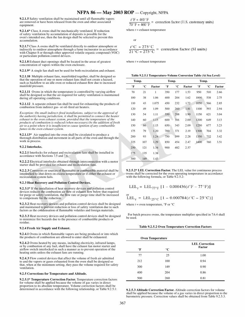
367
NFPA 86 — May 2003 ROP — Copyright, NFPA
DRAFT
9.2.1.5 Safety ventilation shall be maintained until all flammable vapors are removed or have been released from the oven and other associated equipment.
9.2.1.6* Class A ovens shall be mechanically ventilated. If reduction of safety ventilation by accumulation of deposits is possible for the oven’s intended use, then the fan design shall be selected to prevent this accumulation.
9.2.1.7 Class A ovens shall be ventilated directly to outdoor atmosphere or indirectly to outdoor atmosphere through a fume incinerator in accordance with Chapter 8 or through other approved volatile organic compound (VOC) or particulate pollution control devices.
9.2.1.8 Exhaust duct openings shall be located in the areas of greatest concentration of vapors within the oven enclosure.
9.2.1.9* A single fan shall not be used for both recirculation and exhaust.
9.2.1.10 Multiple exhaust fans, manifolded together, shall be designed so that the operation of one or more exhaust fans shall not create a hazard, such as backflow to an idle oven or reduced exhaust flow due to increased manifold pressure.
9.2.1.11 Ovens in which the temperature is controlled by varying airflow shall be designed so that the air required for safety ventilation is maintained during all operating conditions.
9.2.1.12 A separate exhaust fan shall be used for exhausting the products of combustion from indirect gas- or oil-fired air heaters.
Exception: On small indirect-fired installations, subject to the approval of the authority having jurisdiction, it shall be permitted to connect the heater exhaust to the oven exhaust system, provided that the temperature of the products of combustion is reduced (when necessary) by the addition of fresh air to a point where it is insufficient to cause ignition of any combustible fumes in the oven exhaust system.
9.2.1.13* Air supplied into the oven shall be circulated to produce a thorough distribution and movement in all parts of the oven and through the work in process.
9.2.2 Interlocks.
9.2.2.1 Interlocks for exhaust and recirculation fans shall be installed in accordance with Sections 7.5 and 7.6.
9.2.2.2 Electrical interlocks obtained through interconnection with a motor starter shall be provided for exhaust and recirculation fans.
9.2.2.3 Conveyors or sources of flammable or combustible material shall be interlocked to shut down on excess temperature or if either the exhaust or recirculation system fails.
9.2.3 Heat Recovery and Pollution Control Devices.
9.2.3.1* If the installation of heat recovery devices and pollution control devices reduces the combustion air flow or exhaust flow below that required for purge or safety ventilation, the flow rate or purge time shall be increased to compensate for the reduction.
9.2.3.2 Heat recovery devices and pollution control devices shall be designed and maintained to prevent reduction or loss of safety ventilation due to such factors as the condensation of flammable volatiles and foreign materials.
9.2.3.3 Heat recovery devices and pollution control devices shall be designed to minimize fire hazards due to the presence of combustible products or residue.
9.2.4 Fresh Air Supply and Exhaust.
9.2.4.1 Ovens in which flammable vapors are being produced or into which the products of combustion are allowed to enter shall be exhausted.
9.2.4.2 Ovens heated by any means, including electricity, infrared lamps, or by combustion of any fuel, shall have the exhaust fan motor starter and airflow switch interlocked in such a manner as to prevent operation of the heating units unless the exhaust fans are running.
9.2.4.3 Flow control devices that affect the volume of fresh air admitted to and the vapors or gases exhausted from the oven shall be designed so that, when at the minimum setting, they pass the volume required for safety ventilation.
9.2.5 Corrections for Temperature and Altitude.
9.2.5.1* Temperature Correction Factor. Temperature correction factors for volume shall be applied because the volume of gas varies in direct proportion to its absolute temperature. Volume correction factors shall be determined in accordance with the following relationship, or Table 9.2.5.1:
where t = exhaust temperature
or
where t = exhaust temperature
Table 9.2.5.1 Temperature–Volume Conversion Table (At Sea Level)
Temp. Temp. Temp.
°F °C Factor °F °C Factor °F °C Factor
70 21 1 350 177 1.53 950 510 2.66
100 38 1.06 400 204 1.62 1000 538 2.75
110 43 1.075 450 232 1.72 1050 566 2.85
120 49 1.09 500 260 1.81 1100 593 2.94
130 54 1.11 550 288 1.90 1150 621 3.04
140 60 1.13 600 316 2.00 1200 649 3.13
150 66 1.15 650 343 2.09 1250 677 3.23
175 79 1.20 700 371 2.19 1300 704 3.32
200 93 1.24 750 399 2.28 1350 732 3.42
225 107 1.29 850 454 2.47 1400 760 3.51
250 121 1.34 900 482 2.57
275 135 1.38
300 149 1.43
9.2.5.2* LEL Correction Factor. The LEL value for continuous process ovens shall be corrected for the oven operating temperature in accordance with the following formula, or Table 9.2.5.2:
or
where t = oven temperature, °F or °C
For batch process ovens, the temperature multiplier specified in 7.6.4 shall be used.
Table 9.2.5.2 Oven Temperature Correction Factors
Oven Temperature
LEL CorrectionFactor
°F °C
77 25 1.00
212 100 0.94
300 149 0.90
400 204 0.86
500 260 0.81
9.2.5.3 Altitude Correction Factor. Altitude correction factors for volume shall be applied because the volume of a gas varies in direct proportion to the barometric pressure. Correction values shall be obtained from Table 9.2.5.3.
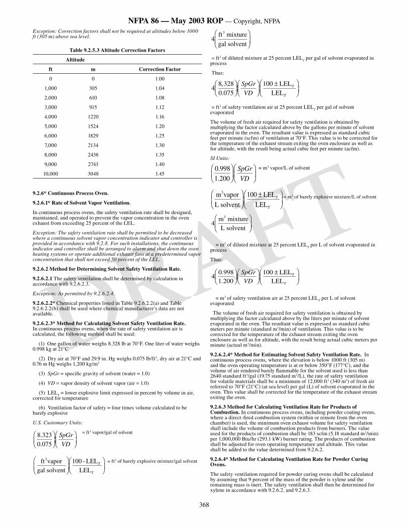
368
NFPA 86 — May 2003 ROP — Copyright, NFPA
DRAFT
Exception: Correction factors shall not be required at altitudes below 1000 ft (305 m) above sea level.
Table 9.2.5.3 Altitude Correction Factors
Altitude
ft m Correction Factor
0 0 1.00
1,000 305 1.04
2,000 610 1.08
3,000 915 1.12
4,000 1220 1.16
5,000 1524 1.20
6,000 1829 1.25
7,000 2134 1.30
8,000 2438 1.35
9,000 2743 1.40
10,000 3048 1.45
9.2.6* Continuous Process Oven.
9.2.6.1* Rate of Solvent Vapor Ventilation.
In continuous process ovens, the safety ventilation rate shall be designed, maintained, and operated to prevent the vapor concentration in the oven exhaust from exceeding 25 percent of the LEL.
Exception: The safety ventilation rate shall be permitted to be decreased where a continuous solvent vapor concentration indicator and controller is provided in accordance with 9.2.8. For such installations, the continuous indicator and controller shall be arranged to alarm and shut down the oven heating systems or operate additional exhaust fans at a predetermined vapor concentration that shall not exceed 50 percent of the LEL.
9.2.6.2 Method for Determining Solvent Safety Ventilation Rate.
9.2.6.2.1 The safety ventilation shall be determined by calculation in accordance with 9.2.6.2.3.
Exception: As permitted by 9.2.6.2.4.
9.2.6.2.2* Chemical properties listed in Table 9.2.6.2.2(a) and Table 9.2.6.2.2(b) shall be used where chemical manufacturer’s data are not available.
9.2.6.2.3* Method for Calculating Solvent Safety Ventilation Rate. In continuous process ovens, when the rate of safety ventilation air is calculated, the following method shall be used:
(1) One gallon of water weighs 8.328 lb at 70°F. One liter of water weighs 0.998 kg at 21°C
(2) Dry air at 70°F and 29.9 in. Hg weighs 0.075 lb/ft3, dry air at 21°C and 0.76 m Hg weighs 1,200 kg/m3
(3) SpGr = specific gravity of solvent (water = 1.0)
(4) VD = vapor density of solvent vapor (air = 1.0)
(5) LELT = lower explosive limit expressed in percent by volume in air,
corrected for temperature
(6) Ventilation factor of safety = four times volume calculated to be barely explosive
U.S. Customary Units:
8 3230 075
.
.
���
������
���
SpGr
VD
= ft3 vapor/gal of solvent
ft vaporgal solvent
- LELLEL
3�
���
�����
���
100 T
T
= ft3 of barely explosive mixture/gal solvent
4ft mixturegal solvent
3�
���
��
= ft3 of diluted mixture at 25 percent LELT per gal of solvent evaporated in
process
Thus:
48 3280 075
100,.
���
������
���
����
���
SpGr
VDT
T
LELLEL
= ft3 of safety ventilation air at 25 percent LELT per gal of solvent
evaporated
The volume of fresh air required for safety ventilation is obtained by multiplying the factor calculated above by the gallons per minute of solvent evaporated in the oven. The resultant value is expressed as standard cubic feet per minute (scfm) of ventilation at 70°F. This value is to be corrected for the temperature of the exhaust stream exiting the oven enclosure as well as for altitude, with the result being actual cubic feet per minute (acfm).
SI Units:
0 9981 200
.
.
���
������
���
SpGr
VD
= m3 vapor/L of solvent
m vaporL solvent
LELLEL
3���
���
����
���
100 T
T
= m3 of barely explosive mixture/L of solvent
4m mixtureL solvent
3�
���
��
= m3 of diluted mixture at 25 percent LELT per L of solvent evaporated in
process
Thus:
40 9981 200
100..
���
������
���
����
���
SpGr
VD
LELLEL
T
T
= m3 of safety ventilation air at 25 percent LELT per L of solvent
evaporated
The volume of fresh air required for safety ventilation is obtained by multiplying the factor calculated above by the liters per minute of solvent evaporated in the oven. The resultant value is expressed as standard cubic meters per minute (standard m3/min) of ventilation. This value is to be corrected for the temperature of the exhaust stream exiting the oven enclosure as well as for altitude, with the result being actual cubic meters per minute (actual m3/min).
9.2.6.2.4* Method for Estimating Solvent Safety Ventilation Rate. In continuous process ovens, where the elevation is below 1000 ft (305 m) and the oven operating temperature is at or below 350°F (177°C), and the volume of air rendered barely flammable for the solvent used is less than 2640 standard ft3/gal (19.75 standard m3/L), the rate of safety ventilation for volatile materials shall be a minimum of 12,000 ft3 (340 m3) of fresh air referred to 70°F (21°C) (at sea level) per gal (L) of solvent evaporated in the oven. This value shall be corrected for the temperature of the exhaust stream exiting the oven.
9.2.6.3 Method for Calculating Ventilation Rate for Products of Combustion. In continuous process ovens, including powder coating ovens, where a direct-fired combustion system (within or remote from the oven chamber) is used, the minimum oven exhaust volume for safety ventilation shall include the volume of combustion products from burners. The value used for the products of combustion shall be 183 scfm (5.18 standard m3/min) per 1,000,000 Btu/hr (293.1 kW) burner rating. The products of combustion shall be adjusted for oven operating temperature and altitude. This value shall be added to the value determined from 9.2.6.2.
9.2.6.4* Method for Calculating Ventilation Rate for Powder Curing Ovens.
The safety ventilation required for powder curing ovens shall be calculated by assuming that 9 percent of the mass of the powder is xylene and the remaining mass is inert. The safety ventilation shall then be determined for xylene in accordance with 9.2.6.2. and 9.2.6.3.
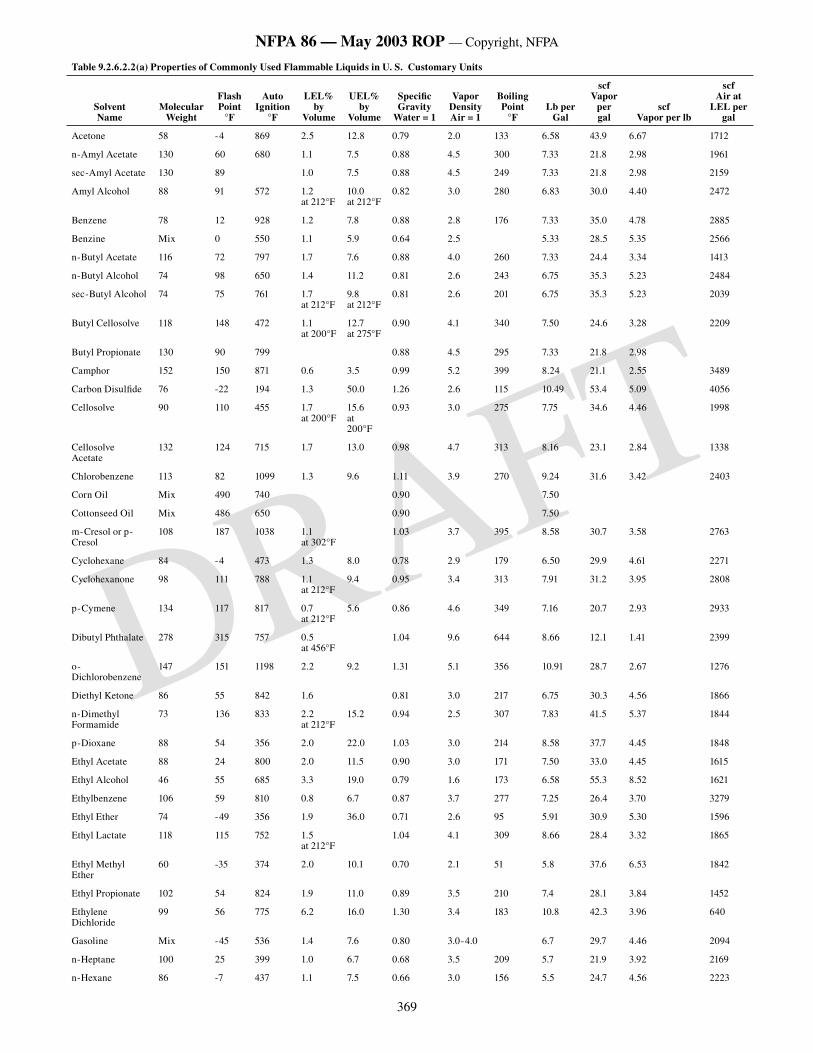
369
NFPA 86 — May 2003 ROP — Copyright, NFPA
DRAFT
Table 9.2.6.2.2(a) Properties of Commonly Used Flammable Liquids in U. S. Customary Units
SolventName
Molecular Weight
Flash Point
°F
Auto Ignition
°F
LEL% by
Volume
UEL% by
Volume
Specific Gravity
Water = 1
Vapor Density Air = 1
Boiling Point
°FLb per
Gal
scfVapor
per gal
scfVapor per lb
scfAir at
LEL per gal
Acetone 58 -4 869 2.5 12.8 0.79 2.0 133 6.58 43.9 6.67 1712
n-Amyl Acetate 130 60 680 1.1 7.5 0.88 4.5 300 7.33 21.8 2.98 1961
sec-Amyl Acetate 130 89 1.0 7.5 0.88 4.5 249 7.33 21.8 2.98 2159
Amyl Alcohol 88 91 572 1.2 at 212°F
10.0 at 212°F
0.82 3.0 280 6.83 30.0 4.40 2472
Benzene 78 12 928 1.2 7.8 0.88 2.8 176 7.33 35.0 4.78 2885
Benzine Mix 0 550 1.1 5.9 0.64 2.5 5.33 28.5 5.35 2566
n-Butyl Acetate 116 72 797 1.7 7.6 0.88 4.0 260 7.33 24.4 3.34 1413
n-Butyl Alcohol 74 98 650 1.4 11.2 0.81 2.6 243 6.75 35.3 5.23 2484
sec-Butyl Alcohol 74 75 761 1.7 at 212°F
9.8 at 212°F
0.81 2.6 201 6.75 35.3 5.23 2039
Butyl Cellosolve 118 148 472 1.1 at 200°F
12.7 at 275°F
0.90 4.1 340 7.50 24.6 3.28 2209
Butyl Propionate 130 90 799 0.88 4.5 295 7.33 21.8 2.98
Camphor 152 150 871 0.6 3.5 0.99 5.2 399 8.24 21.1 2.55 3489
Carbon Disulfide 76 -22 194 1.3 50.0 1.26 2.6 115 10.49 53.4 5.09 4056
Cellosolve 90 110 455 1.7 at 200°F
15.6 at 200°F
0.93 3.0 275 7.75 34.6 4.46 1998
Cellosolve Acetate
132 124 715 1.7 13.0 0.98 4.7 313 8.16 23.1 2.84 1338
Chlorobenzene 113 82 1099 1.3 9.6 1.11 3.9 270 9.24 31.6 3.42 2403
Corn Oil Mix 490 740 0.90 7.50
Cottonseed Oil Mix 486 650 0.90 7.50
m-Cresol or p-Cresol
108 187 1038 1.1 at 302°F
1.03 3.7 395 8.58 30.7 3.58 2763
Cyclohexane 84 -4 473 1.3 8.0 0.78 2.9 179 6.50 29.9 4.61 2271
Cyclohexanone 98 111 788 1.1 at 212°F
9.4 0.95 3.4 313 7.91 31.2 3.95 2808
p-Cymene 134 117 817 0.7 at 212°F
5.6 0.86 4.6 349 7.16 20.7 2.93 2933
Dibutyl Phthalate 278 315 757 0.5 at 456°F
1.04 9.6 644 8.66 12.1 1.41 2399
o-Dichlorobenzene
147 151 1198 2.2 9.2 1.31 5.1 356 10.91 28.7 2.67 1276
Diethyl Ketone 86 55 842 1.6 0.81 3.0 217 6.75 30.3 4.56 1866
n-Dimethyl Formamide
73 136 833 2.2 at 212°F
15.2 0.94 2.5 307 7.83 41.5 5.37 1844
p-Dioxane 88 54 356 2.0 22.0 1.03 3.0 214 8.58 37.7 4.45 1848
Ethyl Acetate 88 24 800 2.0 11.5 0.90 3.0 171 7.50 33.0 4.45 1615
Ethyl Alcohol 46 55 685 3.3 19.0 0.79 1.6 173 6.58 55.3 8.52 1621
Ethylbenzene 106 59 810 0.8 6.7 0.87 3.7 277 7.25 26.4 3.70 3279
Ethyl Ether 74 -49 356 1.9 36.0 0.71 2.6 95 5.91 30.9 5.30 1596
Ethyl Lactate 118 115 752 1.5 at 212°F
1.04 4.1 309 8.66 28.4 3.32 1865
Ethyl Methyl Ether
60 -35 374 2.0 10.1 0.70 2.1 51 5.8 37.6 6.53 1842
Ethyl Propionate 102 54 824 1.9 11.0 0.89 3.5 210 7.4 28.1 3.84 1452
Ethylene Dichloride
99 56 775 6.2 16.0 1.30 3.4 183 10.8 42.3 3.96 640
Gasoline Mix -45 536 1.4 7.6 0.80 3.0-4.0 6.7 29.7 4.46 2094
n-Heptane 100 25 399 1.0 6.7 0.68 3.5 209 5.7 21.9 3.92 2169
n-Hexane 86 -7 437 1.1 7.5 0.66 3.0 156 5.5 24.7 4.56 2223
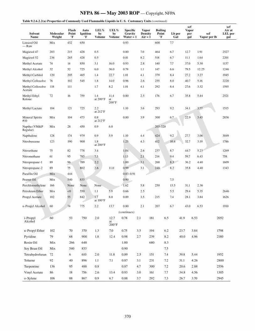
370
NFPA 86 — May 2003 ROP — Copyright, NFPA
DRAFT
Table 9.2.6.2.2(a) Properties of Commonly Used Flammable Liquids in U. S. Customary Units (continued)
SolventName
Molecular Weight
Flash Point
°F
Auto Ignition
°F
LEL% by
Volume
UEL% by
Volume
Specific Gravity
Water = 1
Vapor Density Air = 1
Boiling Point
°FLb per
Gal
scfVapor
per gal
scfVapor per lb
scfAir at
LEL per gal
Linseed Oil — Raw
Mix 432 650 0.93 600 7.7
Magiesol 47 203 215 428 0.5 0.80 7.0 464 6.7 12.7 1.91 2527
Magiesol 52 236 265 428 0.5 0.81 8.2 518 6.7 11.1 1.64 2201
Methyl Acetate 74 14 850 3.1 16.0 0.93 2.8 140 7.7 37.0 5.30 1157
Methyl Alcohol 32 52 725 6.0 36.0 0.79 1.1 147 6.6 79.5 12.25 1246
Methyl Carbitol 120 205 465 1.4 22.7 1.01 4.1 379 8.4 27.2 3.27 1945
Methyl Cellosolve 76 102 545 1.8 14.0 0.96 2.6 255 8.0 40.7 5.16 2220
Methyl Cellosolve Acetate
118 111 1.7 8.2 1.01 4.1 292 8.4 27.6 3.32 1595
Methyl Ethyl Ketone
72 16 759 1.4 at 200°F
11.4 at 200°F
0.80 2.5 176 6.7 35.8 5.44 2521
Methyl Lactate 104 121 725 2.2 at 212°F
1.10 3.6 293 9.2 34.1 3.77 1515
Mineral Spirits #10
Mix 104 473 0.8 at 212°F
0.80 3.9 300 6.7 22.9 3.43 2836
Naptha (VM&P Regular)
Mix 28 450 0.9 6.0 203-320
Napthalene 128 174 979 0.9 5.9 1.10 4.4 424 9.2 27.7 3.06 3049
Nitrobenzene 123 190 900 1.8 at 200°F
1.25 4.3 412 10.4 32.7 3.19 1786
Nitroethane 75 82 778 3.4 1.04 2.6 237 8.7 44.7 5.23 1269
Nitromethane 61 95 785 7.3 1.13 2.1 214 9.4 59.7 6.43 758
Nitropropane-1 89 96 789 2.2 1.00 3.1 268 8.3 36.2 4.40 1609
Nitropropane-2 89 75 802 2.6 11.0 0.99 3.1 248 8.2 35.8 4.40 1343
Paraffin Oil Mix 444 0.83-0.91
Peanut Oil Mix 540 833 0.90 7.5
Perchloroethylene 166 None None None 1.62 5.8 250 13.5 31.1 2.36
Petroleum Ether Mix <0 550 1.1 5.9 0.66 2.5 5.5 29.4 5.35 2646
Propyl Acetate 102 55 842 1.7 at 100°F
8.0 0.89 3.5 215 7.4 28.1 3.84 1626
n-Propyl Alcohol
(continues)
i-Propyl Alcohol
60 53 750 2.0 12.7 at 200°F
0.78 2.1 181 6.5 41.9 6.53 2052
n-Propyl Ether 102 70 370 1.3 7.0 0.75 3.5 194 6.2 23.7 3.84 1798
Pyridine 79 68 900 1.8 12.4 0.98 2.7 239 8.2 40.0 4.96 2180
Rosin Oil Mix 266 648 1.00 680 8.3
Soy Bean Oil Mix 540 833 0.90 7.5
Tetrahydrofuran 72 6 610 2.0 11.8 0.89 2.5 151 7.4 39.8 5.44 1952
Toluene 92 40 896 1.1 7.1 0.87 3.1 231 7.2 31.1 4.26 2800
Turpentine 136 95 488 0.8 0.87 4.7 300 7.2 20.6 2.88 2556
Vinyl Acetate 86 18 756 2.6 13.4 0.93 3.0 161 7.7 34.8 4.56 1305
o-Xylene 106 88 867 0.9 6.7 0.88 3.7 292 7.3 26.7 3.70 2945
60 74 775 2.2 13.7 0.80 2.1 207 6.7 43.0 6.53 1910
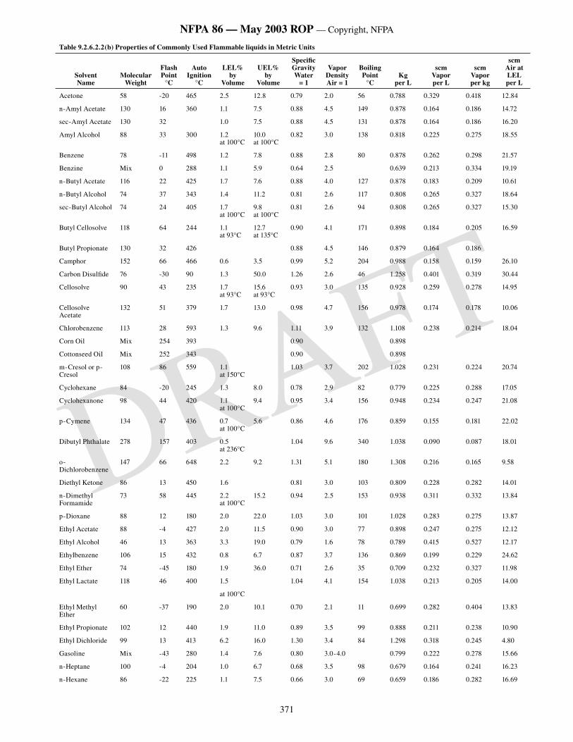
371
NFPA 86 — May 2003 ROP — Copyright, NFPA
DRAFT
Table 9.2.6.2.2(b) Properties of Commonly Used Flammable liquids in Metric Units
SolventName
Molecular Weight
Flash Point
°C
Auto Ignition
°C
LEL% by
Volume
UEL% by
Volume
Specific Gravity Water
= 1
Vapor DensityAir = 1
Boiling Point
°CKg
per L
scmVapor per L
scmVapor per kg
scmAir at LEL per L
Acetone 58 -20 465 2.5 12.8 0.79 2.0 56 0.788 0.329 0.418 12.84
n-Amyl Acetate 130 16 360 1.1 7.5 0.88 4.5 149 0.878 0.164 0.186 14.72
sec-Amyl Acetate 130 32 1.0 7.5 0.88 4.5 131 0.878 0.164 0.186 16.20
Amyl Alcohol 88 33 300 1.2 at 100°C
10.0 at 100°C
0.82 3.0 138 0.818 0.225 0.275 18.55
Benzene 78 -11 498 1.2 7.8 0.88 2.8 80 0.878 0.262 0.298 21.57
Benzine Mix 0 288 1.1 5.9 0.64 2.5 0.639 0.213 0.334 19.19
n-Butyl Acetate 116 22 425 1.7 7.6 0.88 4.0 127 0.878 0.183 0.209 10.61
n-Butyl Alcohol 74 37 343 1.4 11.2 0.81 2.6 117 0.808 0.265 0.327 18.64
sec-Butyl Alcohol 74 24 405 1.7 at 100°C
9.8 at 100°C
0.81 2.6 94 0.808 0.265 0.327 15.30
Butyl Cellosolve 118 64 244 1.1 at 93°C
12.7 at 135°C
0.90 4.1 171 0.898 0.184 0.205 16.59
Butyl Propionate 130 32 426 0.88 4.5 146 0.879 0.164 0.186
Camphor 152 66 466 0.6 3.5 0.99 5.2 204 0.988 0.158 0.159 26.10
Carbon Disulfide 76 -30 90 1.3 50.0 1.26 2.6 46 1.258 0.401 0.319 30.44
Cellosolve 90 43 235 1.7 at 93°C
15.6 at 93°C
0.93 3.0 135 0.928 0.259 0.278 14.95
Cellosolve Acetate
132 51 379 1.7 13.0 0.98 4.7 156 0.978 0.174 0.178 10.06
Chlorobenzene 113 28 593 1.3 9.6 1.11 3.9 132 1.108 0.238 0.214 18.04
Corn Oil Mix 254 393 0.90 0.898
Cottonseed Oil Mix 252 343 0.90 0.898
m-Cresol or p-Cresol
108 86 559 1.1 at 150°C
1.03 3.7 202 1.028 0.231 0.224 20.74
Cyclohexane 84 -20 245 1.3 8.0 0.78 2.9 82 0.779 0.225 0.288 17.05
Cyclohexanone 98 44 420 1.1 at 100°C
9.4 0.95 3.4 156 0.948 0.234 0.247 21.08
p-Cymene 134 47 436 0.7 at 100°C
5.6 0.86 4.6 176 0.859 0.155 0.181 22.02
Dibutyl Phthalate 278 157 403 0.5 at 236°C
1.04 9.6 340 1.038 0.090 0.087 18.01
o-Dichlorobenzene
147 66 648 2.2 9.2 1.31 5.1 180 1.308 0.216 0.165 9.58
Diethyl Ketone 86 13 450 1.6 0.81 3.0 103 0.809 0.228 0.282 14.01
n-Dimethyl Formamide
73 58 445 2.2 at 100°C
15.2 0.94 2.5 153 0.938 0.311 0.332 13.84
p-Dioxane 88 12 180 2.0 22.0 1.03 3.0 101 1.028 0.283 0.275 13.87
Ethyl Acetate 88 -4 427 2.0 11.5 0.90 3.0 77 0.898 0.247 0.275 12.12
Ethyl Alcohol 46 13 363 3.3 19.0 0.79 1.6 78 0.789 0.415 0.527 12.17
Ethylbenzene 106 15 432 0.8 6.7 0.87 3.7 136 0.869 0.199 0.229 24.62
Ethyl Ether 74 -45 180 1.9 36.0 0.71 2.6 35 0.709 0.232 0.327 11.98
Ethyl Lactate 118 46 400 1.5 1.04 4.1 154 1.038 0.213 0.205 14.00
at 100°C
Ethyl Methyl Ether
60 -37 190 2.0 10.1 0.70 2.1 11 0.699 0.282 0.404 13.83
Ethyl Propionate 102 12 440 1.9 11.0 0.89 3.5 99 0.888 0.211 0.238 10.90
Ethyl Dichloride 99 13 413 6.2 16.0 1.30 3.4 84 1.298 0.318 0.245 4.80
Gasoline Mix -43 280 1.4 7.6 0.80 3.0-4.0 0.799 0.222 0.278 15.66
n-Heptane 100 -4 204 1.0 6.7 0.68 3.5 98 0.679 0.164 0.241 16.23
n-Hexane 86 -22 225 1.1 7.5 0.66 3.0 69 0.659 0.186 0.282 16.69
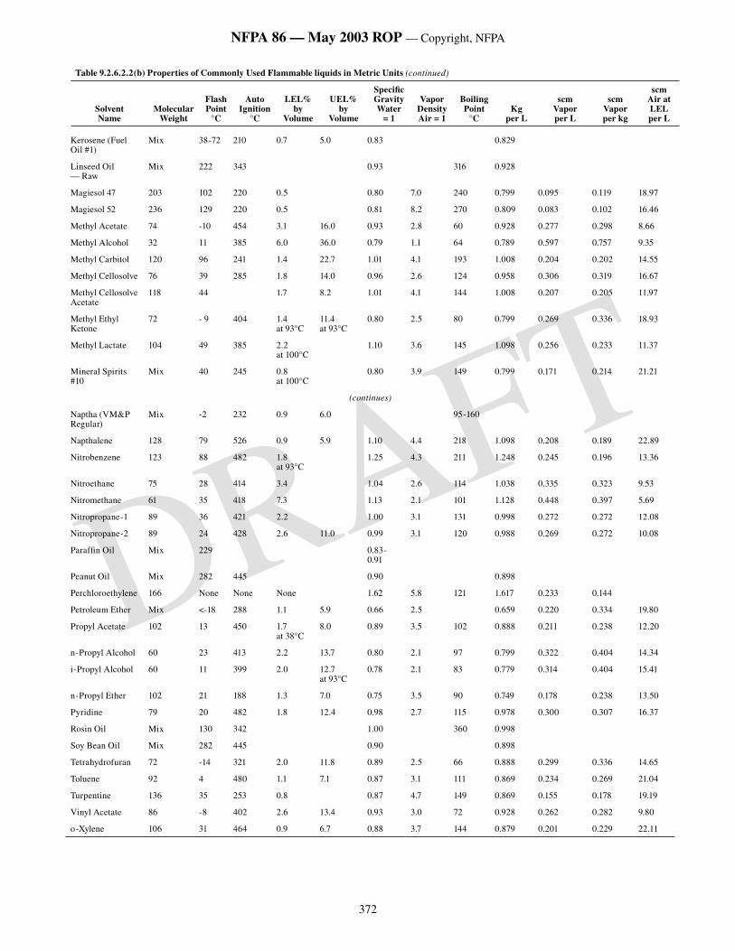
372
NFPA 86 — May 2003 ROP — Copyright, NFPA
DRAFT
Table 9.2.6.2.2(b) Properties of Commonly Used Flammable liquids in Metric Units (continued)
SolventName
Molecular Weight
Flash Point
°C
Auto Ignition
°C
LEL% by
Volume
UEL% by
Volume
Specific Gravity Water
= 1
Vapor DensityAir = 1
Boiling Point
°CKg
per L
scmVapor per L
scmVapor per kg
scmAir at LEL per L
Kerosene (Fuel Oil #1)
Mix 38-72 210 0.7 5.0 0.83 0.829
Linseed Oil — Raw
Mix 222 343 0.93 316 0.928
Magiesol 47 203 102 220 0.5 0.80 7.0 240 0.799 0.095 0.119 18.97
Magiesol 52 236 129 220 0.5 0.81 8.2 270 0.809 0.083 0.102 16.46
Methyl Acetate 74 -10 454 3.1 16.0 0.93 2.8 60 0.928 0.277 0.298 8.66
Methyl Alcohol 32 11 385 6.0 36.0 0.79 1.1 64 0.789 0.597 0.757 9.35
Methyl Carbitol 120 96 241 1.4 22.7 1.01 4.1 193 1.008 0.204 0.202 14.55
Methyl Cellosolve 76 39 285 1.8 14.0 0.96 2.6 124 0.958 0.306 0.319 16.67
Methyl Cellosolve Acetate
118 44 1.7 8.2 1.01 4.1 144 1.008 0.207 0.205 11.97
Methyl Ethyl Ketone
72 - 9 404 1.4 at 93°C
11.4 at 93°C
0.80 2.5 80 0.799 0.269 0.336 18.93
Methyl Lactate 104 49 385 2.2 at 100°C
1.10 3.6 145 1.098 0.256 0.233 11.37
Mineral Spirits #10
Mix 40 245 0.8 at 100°C
0.80 3.9 149 0.799 0.171 0.214 21.21
(continues)
Naptha (VM&P Regular)
Mix -2 232 0.9 6.0 95-160
Napthalene 128 79 526 0.9 5.9 1.10 4.4 218 1.098 0.208 0.189 22.89
Nitrobenzene 123 88 482 1.8 at 93°C
1.25 4.3 211 1.248 0.245 0.196 13.36
Nitroethane 75 28 414 3.4 1.04 2.6 114 1.038 0.335 0.323 9.53
Nitromethane 61 35 418 7.3 1.13 2.1 101 1.128 0.448 0.397 5.69
Nitropropane-1 89 36 421 2.2 1.00 3.1 131 0.998 0.272 0.272 12.08
Nitropropane-2 89 24 428 2.6 11.0 0.99 3.1 120 0.988 0.269 0.272 10.08
Paraffin Oil Mix 229 0.83-0.91
Peanut Oil Mix 282 445 0.90 0.898
Perchloroethylene 166 None None None 1.62 5.8 121 1.617 0.233 0.144
Petroleum Ether Mix <-18 288 1.1 5.9 0.66 2.5 0.659 0.220 0.334 19.80
Propyl Acetate 102 13 450 1.7 at 38°C
8.0 0.89 3.5 102 0.888 0.211 0.238 12.20
n-Propyl Alcohol 60 23 413 2.2 13.7 0.80 2.1 97 0.799 0.322 0.404 14.34
i-Propyl Alcohol 60 11 399 2.0 12.7 at 93°C
0.78 2.1 83 0.779 0.314 0.404 15.41
n-Propyl Ether 102 21 188 1.3 7.0 0.75 3.5 90 0.749 0.178 0.238 13.50
Pyridine 79 20 482 1.8 12.4 0.98 2.7 115 0.978 0.300 0.307 16.37
Rosin Oil Mix 130 342 1.00 360 0.998
Soy Bean Oil Mix 282 445 0.90 0.898
Tetrahydrofuran 72 -14 321 2.0 11.8 0.89 2.5 66 0.888 0.299 0.336 14.65
Toluene 92 4 480 1.1 7.1 0.87 3.1 111 0.869 0.234 0.269 21.04
Turpentine 136 35 253 0.8 0.87 4.7 149 0.869 0.155 0.178 19.19
Vinyl Acetate 86 -8 402 2.6 13.4 0.93 3.0 72 0.928 0.262 0.282 9.80
o-Xylene 106 31 464 0.9 6.7 0.88 3.7 144 0.879 0.201 0.229 22.11
373
NFPA 86 — May 2003 ROP — Copyright, NFPA
DRAFT
9.2.7* Batch Process Ovens.
9.2.7.1 Chemical properties listed in Table 9.2.6.2.2(a) and Table 9.2.6.2.2(b) shall be used where chemical manufacturer’s data are not available.
9.2.7.2* Method for Estimating Rate of Ventilation. In batch ovens, the safety ventilation rate shall be designed and maintained to provide at least 440 scfm of air per gal (3.29 standard m3/min of air per L) of flammable volatiles in each batch.
Exception No. 1: As permitted in 9.2.7.3.
Exception No. 2: For solvents where the quantity of air necessary to render 1 gal (1 L) of solvent barely explosive exceeds 2640 ft3 (19.75 m3), safety ventilation shall be adjusted in proportion to the ratio of the actual volume of air necessary to render 1 gal (1 L) of these solvents barely explosive to 2640 ft3 (19.75 m3).
CAUTION: Caution shall be used where applying this method to products of low mass that can heat up quickly (such as paper or textiles) or materials coated with very highly volatile solvents. Either condition can produce too high a peak evaporation rate for this method to be used.
9.2.7.3 Method for Calculating Ventilation Rate. The 440 scfm of air per gal (3.29 standard m3/min of air per L) of solvent shall be used unless the maximum evaporation rate is determined by tests run under actual operating conditions. Ventilation shall be furnished, with exhaust fans and other devices maintained and operating, to prevent average concentration in the oven from exceeding 25 percent of the LEL.
Exception No. 1: The safety ventilation rate shall be permitted to be decreased where a continuous vapor concentration high limit controller is provided in accordance with Section 9.2.8. For such installations, the continuous vapor concentration high limit controller shall be arranged to alarm and shut down the oven heating system or operate additional exhaust fans at a predetermined vapor concentration that shall not exceed 50 percent of the LEL.
Exception No. 2: The safety ventilation shall be permitted to be calculated by determining the amount of ventilation air in scf (standard m3) that is rendered barely flammable by the vapor generated in gal per hour (L per hour) of solvent in use. This value shall then be multiplied by an empirical factor of 10 and divided by 60 min/hour to obtain the safety ventilation in scfm (standard m3 /min).
9.2.7.4* Correction Factors. Volumes of air specified or calculated in accordance with 9.2.7.2 or 9.2.7.3 shall be corrected for operating temperature in accordance with 9.2.5.1, for altitude in accordance with 9.2.5.3, and for products of combustion in accordance with 9.2.6.3. In addition, for batch ovens operating at temperatures from 250°F (121°C) to 500°F (260°C), the volume shall be increased by a multiplier of 1.4. For temperatures above 500°F (260°C), the 1.4 correction factor is not appropriate, and the correction factor shall be determined by test.
9.2.8 Continuous Vapor Concentration High Limits and Controllers.
9.2.8.1 Where the safety ventilation rate in the oven has been designed to result in vapor concentrations between 25 percent and 50 percent of the LEL, a continuous vapor concentration high limit controller shall be provided.
9.2.8.2* The continuous vapor concentration high limit controller shall be capable of detecting and responding to process upset conditions in time to alarm and initiate reduction of the vapor concentration before the concentration exceeds 50 percent of the LEL.
9.2.8.3* In the case of an oven having multiple heating zones and having at least one heating zone operating at or above 25 percent of the LEL, all other heating zones shall have a continuous vapor concentration high limit controller.
Exception*: Where it can be shown that a heating zone cannot exceed 25 percent of the LEL in the case of an accidental increase in solvent input, a continuous vapor concentration high limit controller shall not be required for that zone.
9.2.8.4* If a continuous vapor concentration controller is used to modulate the flow of fresh air or exhaust from an oven or zone, there shall be a secondary protection system to prevent an analyzer failure from causing a hazardous condition. This system shall have a separate continuous vapor concentration high limit controller for each zone.
Exception: Limits on damper travel (set for 50 percent LEL for the highest design solvent input) for each zone shall be permitted in lieu of a separate continuous vapor concentration high limit controller for each zone.
9.2.8.5 The continuous vapor concentration controller and the continuous vapor concentration high limit controller shall be calibrated for the application and solvents used.
9.2.8.6 Where a variety of solvents are used, the solvent to which the controller is least sensitive shall be the primary calibration reference.
9.2.8.7 A record of primary and subsequent calibrations shall be maintained and reviewed for drift in the controller response.
9.2.8.8 Malfunction alarms shall be provided to indicate any sample, flow, circuit, or controller power failures. Activation of a malfunction alarm shall initiate action to reduce the solvent concentration to a minimum. The activation of the malfunction alarm shall require operator intervention in accordance with 9.2.8.10.
9.2.8.9* Activation of the continuous vapor concentration high limit controller shall alarm and initiate the automatic reduction of the solvent concentration to a minimum.
9.2.8.10 When the continuous vapor concentration high limit controller alarm is activated in accordance with 9.2.8.9, the process shall be prevented from restarting until the vapor concentration is below the limit level and the operator has manually reset the system.
9.2.8.11 The sensor and the sample system shall be maintained at a temperature that prevents condensation. Sampling lines shall be clean and airtight.
9.2.8.12 The system shall be secured against unauthorized adjustment.
9.2.8.13 Maintenance shall be performed in accordance with manufacturer’s instructions.
9.2.8.14 Calibration shall be performed in accordance with manufacturer’s instructions and shall be performed at least once per month.
9.3 Low-Oxygen Atmosphere Class A Ovens with Solvent Recovery
9.3.1 Scope. Low-oxygen atmosphere Class A ovens with solvent recovery shall be permitted to operate at much higher concentrations of solvent vapor by limiting oxygen concentration. Oxygen concentration shall be maintained low by the addition of inert gas.
9.3.2 General.
9.3.2.1* The equipment, including fans and web seals, shall be especially tight to avoid admission of air.
9.3.2.2* The high solvent concentrations in these oven atmospheres shall require operational and design considerations not addressed in conventional solvent evaporation ovens.
9.3.2.3* An oxygen analyzer and controller shall be used to ensure that the oxygen concentration remains below the value where no mixture is flammable (limiting oxidant concentration). Start-up and shutdown shall avoid the flammable region.
9.3.2.4* Solvent shall be recovered and sent to a solvent storage system.
9.3.3 Application. The oven shall be designed to accommodate the performance of the following procedures for system operation:
(1) Operational procedures to avoid solvent flammable region at all times
(2) Starting and purging of the oven with inert gas to lower the oxygen content to a predetermined level
(3) Heating of the recirculating oven atmosphere to the required process temperature
(4) Introduction of the work load into the oven enclosure
(5) Continuous operation
(6) Shutdown procedures to avoid the flammable region of the solvent
(7) Emergency shutdown procedures
9.3.4 Oven Construction and Location.
9.3.4.1 The following requirements shall be in addition to those described in Chapter 3.
Exception: Explosion relief shall not be required for this type of oven.
9.3.4.2 The oven enclosure and any ductwork to and from the enclosure shall be gastight. Access doors shall be gasketed to minimize leakage and shall be designed to prevent opening during operation.
9.3.4.3* The oven and oven end openings shall be designed to restrict the entrance of air and the exit of solvent vapors.
9.3.4.4 The oven atmosphere circulation system shall be designed to provide the required flow throughout the entire oven and ductwork system to avoid condensation of the flammable solvent.
9.3.5 Inert Gas Generation and Storage Systems.
374
NFPA 86 — May 2003 ROP — Copyright, NFPA
DRAFT
9.3.5.1 The oven system shall have an inert gas supply for oxygen control and purging. Inert gas for reduction and control of oxygen within the oven enclosure and associated equipment shall be any of the following types:
(1) Inert gas generators that burn a combustible gas stoichiometrically to produce an inert gas after removal of water vapor
(2) Pressure swing adsorption producing nitrogen
(3) Nitrogen produced by membrane separation equipment
(4) Nitrogen, carbon dioxide, or other inert gases, produced in liquid form. Such liquefied gases are transported to the site and stored in a liquid storage tank. (See Section 9.3.6.)
9.3.5.2 All storage tanks and compressed gas cylinders shall comply with local, state, and federal codes relating to the types of fluids stored, their pressures, and their temperatures. The applicable NFPA standards shall be followed.
9.3.5.3 Vessels, controls, and piping that maintain their integrity at the maximum/minimum design pressures and temperatures shall be provided.
9.3.5.4 ASME tank relief devices shall be provided and sized, constructed, and tested in accordance with ASME Boiler and Pressure Vessel Code, Section VIII, Division 1.
9.3.5.5 Locations for compressed gas tanks and cylinders shall be selected with adequate consideration given to exposure to buildings, processes, personnel, and other storage facilities. Tables of distances specified in the various NFPA standards shall be followed.
9.3.5.6 Bulk storage systems shall be rated and installed to ensure reliable and uninterrupted flow of inert gas to the user equipment as necessary.
9.3.5.7 Where inert gases are used as safety purge media, the volume stored always shall be sufficient to purge all connected low-oxygen atmosphere ovens with a minimum of five oven volumes (see 9.3.6.1). Recirculating fans shall be kept operating during the purge.
Exception: The stored volume shall be permitted to be reduced, provided both of the following conditions are met:
(1) Mixing is adequate.
(2) The stored volume is sufficient to reduce the concentration in the oven to the LEL in air.
9.3.6 Vaporizers Used for Liquefied Purging Fluids.
9.3.6.1 Vaporizers utilized to convert cryogenic fluids to the gas state shall be ambient air-heated units so that their flow is unaffected by a loss of power.
Exception: Use of powered vaporizers shall be permitted, provided one of the following conditions is met:
(1) The vaporizer has reserve heating capacity sufficient to continue vaporizing at least five oven volumes at the required purge flow rate immediately following power interruption.
(2) Reserve ambient vaporizers are provided that are piped to the source of supply so as to be unaffected by a freeze-up or flow stoppage of gas from the power vaporizer. The reserve vaporizer shall be capable of evaporating at least five oven volumes at the required purge flow rate.
(3) Purge gas is available from an alternate source that fulfills the requirements of 9.3.5.6,
9.3.5.7, 9.3.6.2, and 9.3.6.4.
9.3.6.2 Vaporizers shall be rated by the industrial gas supplier or the owner to vaporize at 150 percent of the highest purge gas demand for all connected equipment. Winter temperature extremes in the locale shall be taken into consideration by the agency responsible for rating them.
9.3.6.3 It shall be the user’s responsibility to inform the industrial gas supplier of additions to the plant that materially increase the inert gas consumption rate so that vaporizer and storage capacity can be enlarged in advance of plant expansion.
9.3.6.4* The vaporizer shall be protected against flow demands that exceed its rate of capacity when this can cause closure of a low-temperature shut-off valve.
9.3.6.5 A temperature indicator shall be installed in the vaporizer effluent piping. An audible or visual low-temperature alarm shall be provided to alert oven operators whenever the temperature is in danger of reaching the set point of the low-temperature flow shut-off valve, so they can begin corrective actions in advance of the flow stoppage.
9.3.7 Inert Gas Flow Rates.
9.3.7.1 Inert gas shall be required to dilute air infiltration, which otherwise can result in the creation of a flammable gas–air mixture within the oven. The flow rate shall be permitted to be varied during the course of the process cycle.
9.3.7.2 Reliable means shall be provided for metering and controlling the flow rate of the inert gas.
9.3.7.3 The flow control shall be accessible and located in an illuminated area so that an operator can readily monitor its operation.
9.3.7.4 Where an inert gas flow control unit is equipped with an automatic emergency inert purge, a manually operated switch located prominently on the face of the unit and a remote switch that activates the purge shall be provided.
9.3.7.5 The pressure of the inert gas system shall be regulated to avoid overpressurizing components in the system, such as glass tube flow meters.
9.3.8 Inert Gas Piping System.
9.3.8.1 The piping system for inert gas shall be sized to allow the full flow of inert gas to all connected ovens at the maximum demand rates.
9.3.8.2 Solders that contain lead shall not be used to join pipes.
9.3.8.3* Piping that contains cryogenic liquids, or that is installed downstream of a cryogenic gas vaporizer, shall be constructed of metals that retain adequate strength at cryogenic temperatures. Piping and piping components shall be in accordance with ASME B31.3, Process Piping.
9.3.9 Safety Equipment and Application.
9.3.9.1* The oven shall be analyzed continuously and controlled for oxygen content by modulating the addition of inert gas. The sample point shall be in the condensing system for each zone or multiple zones. The oven shall have a minimum of two analyzers to provide redundancy.
9.3.9.2 An emergency standby power generator shall be provided for emergency shutdown during a power failure.
Exception: This equipment shall not be required if alternate safety shutdown procedures for power failure are employed.
9.3.9.3* Provisions shall be made to restrict entry into the oven where the atmosphere could be hazardous to human health.
9.3.10 Inert Gas Introduction and Starting the Production Line.
9.3.10.1 The following items shall be accomplished for inert gas introduction and starting the production line:
(1) The operator shall ensure that all personnel are out of the oven enclosure, all guards are in place, and doors are closed.
(2) The operator shall verify that an adequate volume of inert gas is in storage and the inert gas supply and solvent recovery systems are operational and ready to start production.
(3) The solvent recovery system interfaced with the oven shall be operational and prepared to receive solvent-laden gas prior to starting production.
(4) The recirculation fans shall be started in the oven enclosure prior to introduction of inert gas, which ensures that effective oxygen purging occurs once inert gas enters the enclosure.
(5) The oven enclosure shall be purged with inert gas until the enclosure oxygen concentration is 3 percentage points below the limiting oxidant concentration (LOC) that can support combustion of the solvents used. (See Table 9.3.10.1.)
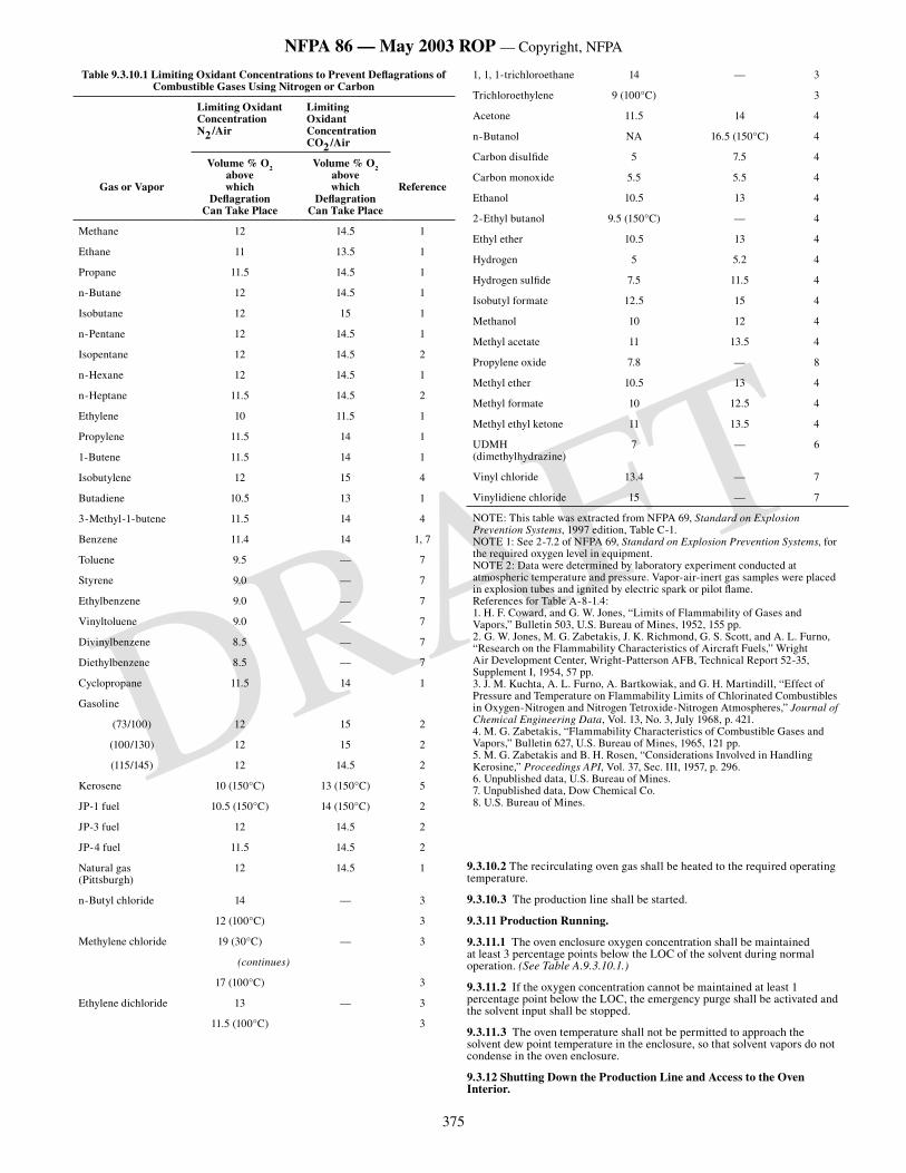
375
NFPA 86 — May 2003 ROP — Copyright, NFPA
DRAFT
Table 9.3.10.1 Limiting Oxidant Concentrations to Prevent Deflagrations of Combustible Gases Using Nitrogen or Carbon
Limiting OxidantConcentrationN2 /Air
Limiting OxidantConcentrationCO2 /Air
Gas or Vapor
Volume % O2 abovewhich
DeflagrationCan Take Place
Volume % O2 abovewhich
DeflagrationCan Take Place
Reference
Methane 12 14.5 1
Ethane 11 13.5 1
Propane 11.5 14.5 1
n-Butane 12 14.5 1
Isobutane 12 15 1
n-Pentane 12 14.5 1
Isopentane 12 14.5 2
n-Hexane 12 14.5 1
n-Heptane 11.5 14.5 2
Ethylene 10 11.5 1
Propylene 11.5 14 1
1-Butene 11.5 14 1
Isobutylene 12 15 4
Butadiene 10.5 13 1
3-Methyl-1-butene 11.5 14 4
Benzene 11.4 14 1, 7
Toluene 9.5 — 7
Styrene 9.0 — 7
Ethylbenzene 9.0 — 7
Vinyltoluene 9.0 — 7
Divinylbenzene 8.5 — 7
Diethylbenzene 8.5 — 7
Cyclopropane 11.5 14 1
Gasoline
(73/100) 12 15 2
(100/130) 12 15 2
(115/145) 12 14.5 2
Kerosene 10 (150°C) 13 (150°C) 5
JP-1 fuel 10.5 (150°C) 14 (150°C) 2
JP-3 fuel 12 14.5 2
JP-4 fuel 11.5 14.5 2
Natural gas (Pittsburgh)
12 14.5 1
n-Butyl chloride 14 — 3
12 (100°C) 3
Methylene chloride 19 (30°C) — 3
(continues)
17 (100°C) 3
Ethylene dichloride 13 — 3
11.5 (100°C) 3
1, 1, 1-trichloroethane 14 — 3
Trichloroethylene 9 (100°C) 3
Acetone 11.5 14 4
n-Butanol NA 16.5 (150°C) 4
Carbon disulfide 5 7.5 4
Carbon monoxide 5.5 5.5 4
Ethanol 10.5 13 4
2-Ethyl butanol 9.5 (150°C) — 4
Ethyl ether 10.5 13 4
Hydrogen 5 5.2 4
Hydrogen sulfide 7.5 11.5 4
Isobutyl formate 12.5 15 4
Methanol 10 12 4
Methyl acetate 11 13.5 4
Propylene oxide 7.8 — 8
Methyl ether 10.5 13 4
Methyl formate 10 12.5 4
Methyl ethyl ketone 11 13.5 4
UDMH (dimethylhydrazine)
7 — 6
Vinyl chloride 13.4 — 7
Vinylidiene chloride 15 — 7
NOTE: This table was extracted from NFPA 69, Standard on Explosion Prevention Systems, 1997 edition, Table C-1.NOTE 1: See 2-7.2 of NFPA 69, Standard on Explosion Prevention Systems, for the required oxygen level in equipment.NOTE 2: Data were determined by laboratory experiment conducted at atmospheric temperature and pressure. Vapor-air-inert gas samples were placed in explosion tubes and ignited by electric spark or pilot flame.References for Table A-8-1.4:1. H. F. Coward, and G. W. Jones, “Limits of Flammability of Gases and Vapors,” Bulletin 503, U.S. Bureau of Mines, 1952, 155 pp.2. G. W. Jones, M. G. Zabetakis, J. K. Richmond, G. S. Scott, and A. L. Furno, “Research on the Flammability Characteristics of Aircraft Fuels,” Wright Air Development Center, Wright-Patterson AFB, Technical Report 52-35, Supplement I, 1954, 57 pp.3. J. M. Kuchta, A. L. Furno, A. Bartkowiak, and G. H. Martindill, “Effect of Pressure and Temperature on Flammability Limits of Chlorinated Combustibles in Oxygen-Nitrogen and Nitrogen Tetroxide-Nitrogen Atmospheres,” Journal of Chemical Engineering Data, Vol. 13, No. 3, July 1968, p. 421.4. M. G. Zabetakis, “Flammability Characteristics of Combustible Gases and Vapors,” Bulletin 627, U.S. Bureau of Mines, 1965, 121 pp.5. M. G. Zabetakis and B. H. Rosen, “Considerations Involved in Handling Kerosine,” Proceedings API, Vol. 37, Sec. III, 1957, p. 296.6. Unpublished data, U.S. Bureau of Mines.7. Unpublished data, Dow Chemical Co.8. U.S. Bureau of Mines.
9.3.10.2 The recirculating oven gas shall be heated to the required operating temperature.
9.3.10.3 The production line shall be started.
9.3.11 Production Running.
9.3.11.1 The oven enclosure oxygen concentration shall be maintained at least 3 percentage points below the LOC of the solvent during normal operation. (See Table A.9.3.10.1.)
9.3.11.2 If the oxygen concentration cannot be maintained at least 1 percentage point below the LOC, the emergency purge shall be activated and the solvent input shall be stopped.
9.3.11.3 The oven temperature shall not be permitted to approach the solvent dew point temperature in the enclosure, so that solvent vapors do not condense in the oven enclosure.
9.3.12 Shutting Down the Production Line and Access to the Oven Interior.
376
NFPA 86 — May 2003 ROP — Copyright, NFPA
DRAFT
9.3.12.1 The production line shall be stopped.
9.3.12.2* Flow to and from the solvent recovery system shall be continued and the system shall be purged with inert gas as required until the solvent vapor concentration in the oven enclosure is no greater than the solvent concentration at the LOC. (See Figure A.9.3.12.2.)
9.3.12.3 Flow to and from the solvent recovery system shall be discontinued and oven heaters shall be de-energized.
9.3.12.4* Air shall be introduced into the oven enclosure until the oxygen level reaches a minimum of 19.5 percent. Once this level has been reached, enclosure access shall be permitted.
9.3.13 Emergency Procedures.
9.3.13.1 In the event of electrical power failure, the emergency standby power source shall provide electric power to the purge blowers and the oven safety controls.
Exception: Emergency standby power source shall not be required if alternate safety procedures for power failures are employed.
9.3.13.2 The production line shall shut down automatically when the emergency purge cycle is initiated. The oxygen analyzer that initiates the emergency purge cycle shall be hard-wired to bypass all other process control instrumentation.
9.3.13.3 The oven enclosure shall have an adequate vent line that opens automatically when the emergency purge cycle is initiated in order to avoid pressurizing the oven enclosure. The vent shall discharge to a location away from building makeup air and ignition sources.
9.3.14* Special Operator Training and Maintenance. Operation and maintenance of a low-oxygen oven and its associated recovery equipment shall be performed by the user in accordance with the manufacturer’s recommendations and in accordance with Chapter 10.
Chapter 10 Class B Ovens and Furnaces
10.1 General. The requirements of Chapters 1 through 7 and Chapters 13 and 14 shall apply to Class B ovens and furnaces
10.2* Ventilation of Class B Ovens and Furnaces. If the installation of heat recovery devices and pollution control devices reduces the combustion air flow or exhaust flow below that required for purge, the flow rate or purge time shall be increased to compensate for the reduction.
10.3 Safety Devices for Arc Melting Furnaces.
10.3.1* General. Safety controls for arc melting furnaces shall be designed to prevent operating the furnace unless operating conditions have been established that are within design parameters for the furnace, and to shut down the furnace if operating conditions outside of the design parameters occur. These controls shall be accessible at all times.
10.3.2 Safety Devices.
10.3.2.1 The furnace main disconnect shall be either a circuit breaker or fused switch equipped with all of the following accessories:
(1) Overcurrent relays with inverse time and instantaneous trips
(2) Overcurrent ground-fault relays with inverse time and instantaneous relays
(3) Undervoltage trip relay
(4) Surge protection
(5) Local and remote close/trip switches interlocked by a common key so that only one location is capable of being operated at any time
10.3.2.2 A master lockout switch with a key shall be located at the furnace operator’s panel. This switch shall be connected to a circuit breaker by cables that are separated completely from any other wiring. It shall provide a positive lockout and isolation of the circuit breaker, thereby preventing accidental closure of the breaker by grounds in the closing circuit. The key shall be trapped when the switch is ON and shall be free when in the OFF position. This key shall be kept under the supervision of the authorized operator.
10.3.2.3 Interlocks. Interlocks shall be provided to ensure that all of the following conditions are satisfied before permitting the main disconnect to be closed:
(1) Furnace transformer heat exchangers operating
(2) Oil flowing to furnace heat exchangers (if fitted)
(3) Water flowing to furnace transformer heat exchangers (flow or pressure-proving switch)
(4) Transformer tap changer on tap position (if off-load tap changer fitted)
(5) Furnace transformer oil temperature within operating limits
(6) Furnace transformer winding temperature within operating limits
(7) Gas detector registering no gas in transformer tank
(8) Furnace electrode drive control gear on
(9) All supply voltages on and within operating limits
(10) Furnace roof and electrode swing within operating limits
(11) Furnace within specified limits of forward and backward tilt
(12) Master lockout switch on
(13) Safety shut-off valves on oxygen and fuel lines supplying burners proved closed
10.3.2.4 Interlocks for Main Furnace Structure.
10.3.2.4.1 The main furnace structure shall be interlocked where the arc furnace operation includes tilting of the furnace to remove molten metal at the end of the furnace heat. The furnace shall not be tilted during the melt operation, and the following interlocks shall be provided to prevent furnace tilting until furnace controls have been proven in the correct position. Interlocks shall be fitted to prevent tilting of the furnace unless both of the following conditions are satisfied:
(1) The roof is down.
(2) The limit switches are at forward and backward limits of travel.
10.3.2.4.2 Interlocks shall be fitted to prevent swinging of the roof and electrodes unless the following three conditions are satisfied:
(1) The electrode arms are up and clear of shell.
(2) The furnace tilt platform is normal and locked (if fitted).
(3) The roof is raised.
10.3.2.5 A compressed air line supply for unclamping electrodes shall be fitted with a solenoid valve interlocked with the furnace circuit breaker to ensure that the electrodes cannot be released unless the furnace power is OFF.
10.3.2.6 For burner ignition with the arc, oxy-fuel and oxygen-enriched air burner controls shall be interlocked with the furnace controls. An isolated contact on the arc furnace controls shall be provided for interconnecting the burner management system to establish that enough current is flowing through the secondary leg of the power transformer to maintain a strong arc in the furnace.
Exception*: Operation of a burner shall not be required to be halted in the event of a momentary interruption of the arc, or after arc heating has been intentionally discontinued, provided the contents of the furnace are incandescent or determined to be at a temperature in excess of 1400°F (760°C).
10.3.2.7 Oxy-fuel burners installed on arc-metal heating furnaces shall be exempt from the provisions of Chapters 4 and 5 that require both of the following:
(1) Burner flame pilots or igniters
(2) Combustion safeguards (flame supervision)
Chapter 11 Class C Ovens and Furnaces
11.1 Special Atmospheres.
11.1.1* General.
11.1.1.1 Section 11.1 shall apply to the equipment used to generate or to store special atmospheres and to meter or control their flows to atmosphere furnaces. Section 11.1 shall also apply to generated and synthetic special atmospheres. All the requirements in this standard for furnace heating systems shall apply to generator heating systems, unless otherwise specified in this section.
11.1.1.2 The selection and operation of the equipment used to produce or store special atmospheres shall be the responsibility of the user and shall be subject to the authority having jurisdiction.
11.1.1.3* Unwanted, normal operating, and emergency releases of fluids (gases or liquids) from special atmosphere generators, storage tanks, gas cylinders, and flow control units shall be disposed of to an approved location. Depending upon specific local circumstances and ordinances, the nature of the fluids, and the composition of the gas, then one or more of the following methods shall be employed:
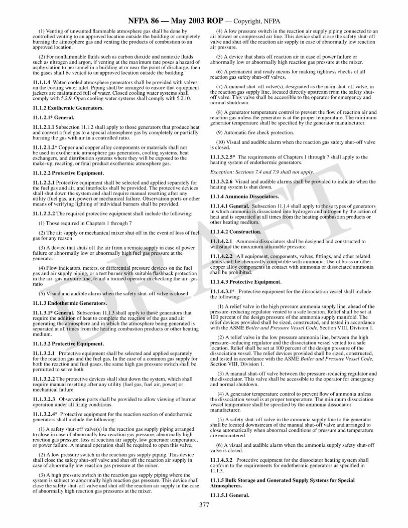
377
NFPA 86 — May 2003 ROP — Copyright, NFPA
DRAFT
(1) Venting of unwanted flammable atmosphere gas shall be done by controlled venting to an approved location outside the building or completely burning the atmosphere gas and venting the products of combustion to an approved location.
(2) For nonflammable fluids such as carbon dioxide and nontoxic fluids such as nitrogen and argon, if venting at the maximum rate poses a hazard of asphyxiation to personnel in a building at or near the point of discharge, then the gases shall be vented to an approved location outside the building.
11.1.1.4 Water-cooled atmosphere generators shall be provided with valves on the cooling water inlet. Piping shall be arranged to ensure that equipment jackets are maintained full of water. Closed cooling water systems shall comply with 5.2.9. Open cooling water systems shall comply with 5.2.10.
11.1.2 Exothermic Generators.
11.1.2.1* General.
11.1.2.1.1 Subsection 11.1.2 shall apply to those generators that produce heat and convert a fuel gas to a special atmosphere gas by completely or partially burning the gas with air in a controlled ratio.
11.1.2.1.2* Copper and copper alloy components or materials shall not be used in exothermic atmosphere gas generators, cooling systems, heat exchangers, and distribution systems where they will be exposed to the make-up, reacting, or final product exothermic atmosphere gas.
11.1.2.2 Protective Equipment.
11.1.2.2.1 Protective equipment shall be selected and applied separately for the fuel gas and air, and interlocks shall be provided. The protective devices shall shut down the system and shall require manual resetting after any utility (fuel gas, air, power) or mechanical failure. Observation ports or other means of verifying lighting of individual burners shall be provided.
11.1.2.2.2 The required protective equipment shall include the following:
(1) Those required in Chapters 1 through 7
(2) The air supply or mechanical mixer shut off in the event of loss of fuel gas for any reason
(3) A device that shuts off the air from a remote supply in case of power failure or abnormally low or abnormally high fuel gas pressure at the generator
(4) Flow indicators, meters, or differential pressure devices on the fuel gas and air supply piping, or a test burner with suitable flashback protection in the air–gas mixture line, to aid a trained operator in checking the air–gas ratio
(5) Visual and audible alarm when the safety shut-off valve is closed
11.1.3 Endothermic Generators.
11.1.3.1* General. Subsection 11.1.3 shall apply to those generators that require the addition of heat to complete the reaction of the gas and air generating the atmosphere and in which the atmosphere being generated is separated at all times from the heating combustion products or other heating medium.
11.1.3.2 Protective Equipment.
11.1.3.2.1 Protective equipment shall be selected and applied separately for the reaction gas and the fuel gas. In the case of a common gas supply for both the reaction and fuel gases, the same high gas pressure switch shall be permitted to serve both.
11.1.3.2.2 The protective devices shall shut down the system, which shall require manual resetting after any utility (fuel gas, fuel air, power) or mechanical failure.
11.1.3.2.3 Observation ports shall be provided to allow viewing of burner operation under all firing conditions.
11.1.3.2.4* Protective equipment for the reaction section of endothermic generators shall include the following:
(1) A safety shut-off valve(s) in the reaction gas supply piping arranged to close in case of abnormally low reaction gas pressure, abnormally high reaction gas pressure, loss of reaction air supply, low generator temperature, or power failure. A manual operation shall be required to open this valve.
(2) A low pressure switch in the reaction gas supply piping. This device shall close the safety shut-off valve and shut off the reaction air supply in case of abnormally low reaction gas pressure at the mixer.
(3) A high pressure switch in the reaction gas supply piping where the system is subject to abnormally high reaction gas pressure. This device shall close the safety shut-off valve and shut off the reaction air supply in the case of abnormally high reaction gas pressures at the mixer.
(4) A low pressure switch in the reaction air supply piping connected to an air blower or compressed air line. This device shall close the safety shut-off valve and shut off the reaction air supply in case of abnormally low reaction air pressure.
(5) A device that shuts off reaction air in case of power failure or abnormally low or abnormally high reaction gas pressure at the mixer.
(6) A permanent and ready means for making tightness checks of all reaction gas safety shut-off valves.
(7) A manual shut-off valve(s), designated as the main shut-off valve, in the reaction gas supply line, located directly upstream from the safety shut-off valve. This valve shall be accessible to the operator for emergency and normal shutdown.
(8) A generator temperature control to prevent the flow of reaction air and reaction gas unless the generator is at the proper temperature. The minimum generator temperature shall be specified by the generator manufacturer.
(9) Automatic fire check protection.
(10) Visual and audible alarm when the reaction gas safety shut-off valve is closed.
11.1.3.2.5* The requirements of Chapters 1 through 7 shall apply to the heating system of endothermic generators.
Exception: Sections 7.4 and 7.9 shall not apply.
11.1.3.2.6 Visual and audible alarms shall be provided to indicate when the heating system is shut down.
11.1.4 Ammonia Dissociators.
11.1.4.1 General. Subsection 11.1.4 shall apply to those types of generators in which ammonia is dissociated into hydrogen and nitrogen by the action of heat and is separated at all times from the heating combustion products or other heating medium.
11.1.4.2 Construction.
11.1.4.2.1 Ammonia dissociators shall be designed and constructed to withstand the maximum attainable pressure.
11.1.4.2.2 All equipment, components, valves, fittings, and other related items shall be chemically compatible with ammonia. Use of brass or other copper alloy components in contact with ammonia or dissociated ammonia shall be prohibited.
11.1.4.3 Protective Equipment.
11.1.4.3.1* Protective equipment for the dissociation vessel shall include the following:
(1) A relief valve in the high pressure ammonia supply line, ahead of the pressure-reducing regulator vented to a safe location. Relief shall be set at 100 percent of the design pressure of the ammonia supply manifold. The relief devices provided shall be sized, constructed, and tested in accordance with the ASME Boiler and Pressure Vessel Code, Section VIII, Division 1.
(2) A relief valve in the low pressure ammonia line, between the high pressure–reducing regulator and the dissociation vessel vented to a safe location. Relief shall be set at 100 percent of the design pressure of the dissociation vessel. The relief devices provided shall be sized, constructed, and tested in accordance with the ASME Boiler and Pressure Vessel Code, Section VIII, Division 1.
(3) A manual shut-off valve between the pressure-reducing regulator and the dissociator. This valve shall be accessible to the operator for emergency and normal shutdown.
(4) A generator temperature control to prevent flow of ammonia unless the dissociation vessel is at proper temperature. The minimum dissociation vessel temperature shall be specified by the ammonia dissociator manufacturer.
(5) A safety shut-off valve in the ammonia supply line to the generator shall be located downstream of the manual shut-off valve and arranged to close automatically when abnormal conditions of pressure and temperature are encountered.
(6) A visual and audible alarm when the ammonia supply safety shut-off valve is closed.
11.1.4.3.2 Protective equipment for the dissociator heating system shall conform to the requirements for endothermic generators as specified in 11.1.3.
11.1.5 Bulk Storage and Generated Supply Systems for Special Atmospheres.
11.1.5.1 General.
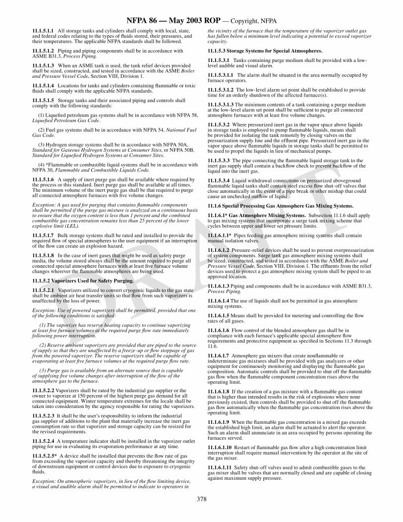
378
NFPA 86 — May 2003 ROP — Copyright, NFPA
DRAFT
11.1.5.1.1 All storage tanks and cylinders shall comply with local, state, and federal codes relating to the types of fluids stored, their pressures, and their temperatures. The applicable NFPA standards shall be followed.
11.1.5.1.2 Piping and piping components shall be in accordance with ASME B31.3, Process Piping.
11.1.5.1.3 When an ASME tank is used, the tank relief devices provided shall be sized, constructed, and tested in accordance with the ASME Boiler and Pressure Vessel Code, Section VIII, Division 1.
11.1.5.1.4 Locations for tanks and cylinders containing flammable or toxic fluids shall comply with the applicable NFPA standards.
11.1.5.1.5 Storage tanks and their associated piping and controls shall comply with the following standards:
(1) Liquefied petroleum gas systems shall be in accordance with NFPA 58, Liquefied Petroleum Gas Code.
(2) Fuel gas systems shall be in accordance with NFPA 54, National Fuel Gas Code.
(3) Hydrogen storage systems shall be in accordance with NFPA 50A, Standard for Gaseous Hydrogen Systems at Consumer Sites, or NFPA 50B, Standard for Liquefied Hydrogen Systems at Consumer Sites.
(4) *Flammable or combustible liquid systems shall be in accordance with NFPA 30, Flammable and Combustible Liquids Code.
11.1.5.1.6 A supply of inert purge gas shall be available where required by the process or this standard. Inert purge gas shall be available at all times. The minimum volume of the inert purge gas shall be that required to purge all connected atmosphere furnaces with five volume changes.
Exception: A gas used for purging that contains flammable components shall be permitted if the purge gas mixture is analyzed on a continuous basis to ensure that the oxygen content is less than 1 percent and the combined combustible gas concentration remains less than 25 percent of the lower explosive limit (LEL).
11.1.5.1.7 Bulk storage systems shall be rated and installed to provide the required flow of special atmospheres to the user equipment if an interruption of the flow can create an explosion hazard.
11.1.5.1.8 In the case of inert gases that might be used as safety purge media, the volume stored always shall be the amount required to purge all connected special atmosphere furnaces with at least five furnace volume changes wherever the flammable atmospheres are being used.
11.1.5.2 Vaporizers Used for Safety Purging.
11.1.5.2.1 Vaporizers utilized to convert cryogenic liquids to the gas state shall be ambient air heat transfer units so that flow from such vaporizers is unaffected by the loss of power.
Exception: Use of powered vaporizers shall be permitted, provided that one of the following conditions is satisfied:
(1) The vaporizer has reserve heating capacity to continue vaporizing at least five furnace volumes at the required purge flow rate immediately following power interruption.
(2) Reserve ambient vaporizers are provided that are piped to the source of supply so that they are unaffected by a freeze-up or flow stoppage of gas from the powered vaporizer. The reserve vaporizers shall be capable of evaporating at least five furnace volumes at the required purge flow rate.
(3) Purge gas is available from an alternate source that is capable of supplying five volume changes after interruption of the flow of the atmosphere gas to the furnace.
11.1.5.2.2 Vaporizers shall be rated by the industrial gas supplier or the owner to vaporize at 150 percent of the highest purge gas demand for all connected equipment. Winter temperature extremes for the locale shall be taken into consideration by the agency responsible for rating the vaporizers.
11.1.5.2.3 It shall be the user’s responsibility to inform the industrial gas supplier of additions to the plant that materially increase the inert gas consumption rate so that vaporizer and storage capacity can be resized for the revised requirements.
11.1.5.2.4 A temperature indicator shall be installed in the vaporizer outlet piping for use in evaluating its evaporation performance at any time.
11.1.5.2.5* A device shall be installed that prevents the flow rate of gas from exceeding the vaporizer capacity and thereby threatening the integrity of downstream equipment or control devices due to exposure to cryogenic fluids.
Exception: On atmospheric vaporizers, in lieu of the flow limiting device, a visual and audible alarm shall be permitted to indicate to operators in
the vicinity of the furnace that the temperature of the vaporizer outlet gas has fallen below a minimum level indicating a potential to exceed vaporizer capacity.
11.1.5.3 Storage Systems for Special Atmospheres.
11.1.5.3.1 Tanks containing purge medium shall be provided with a low-level audible and visual alarm.
11.1.5.3.1.1 The alarm shall be situated in the area normally occupied by furnace operators.
11.1.5.3.1.2 The low-level alarm set point shall be established to provide time for an orderly shutdown of the affected furnace(s).
11.1.5.3.1.3 The minimum contents of a tank containing a purge medium at the low-level alarm set point shall be sufficient to purge all connected atmosphere furnaces with at least five volume changes.
11.1.5.3.2 Where pressurized inert gas in the vapor space above liquids in storage tanks is employed to pump flammable liquids, means shall be provided for isolating the tank remotely by closing valves on the pressurization supply line and the effluent pipe. Pressurized inert gas in the vapor space above flammable liquids in storage tanks shall be permitted to be used to propel the liquids in lieu of mechanical pumps.
11.1.5.3.3 The pipe connecting the flammable liquid storage tank to the inert gas supply shall contain a backflow check to prevent backflow of the liquid into the inert gas.
11.1.5.3.4 Liquid withdrawal connections on pressurized aboveground flammable liquid tanks shall contain steel excess flow shut-off valves that close automatically in the event of a pipe break or other mishap that could cause an unchecked outflow of liquid.
11.1.6 Special Processing Gas Atmosphere Gas Mixing Systems.
11.1.6.1* Gas Atmosphere Mixing Systems. Subsection 11.1.6 shall apply to gas mixing systems that incorporate a surge tank mixing scheme that cycles between upper and lower set pressure limits.
11.1.6.1.1* Pipes feeding gas atmosphere mixing systems shall contain manual isolation valves.
11.1.6.1.2 Pressure-relief devices shall be used to prevent overpressurization of system components. Surge tank gas atmosphere mixing systems shall be sized, constructed, and tested in accordance with the ASME Boiler and Pressure Vessel Code, Section VIII, Division 1. The effluents from the relief devices used to protect a gas atmosphere mixing system shall be piped to an approved location.
11.1.6.1.3 Piping and components shall be in accordance with ASME B31.3, Process Piping.
11.1.6.1.4 The use of liquids shall not be permitted in gas atmosphere mixing systems.
11.1.6.1.5 Means shall be provided for metering and controlling the flow rates of all gases.
11.1.6.1.6 Flow control of the blended atmosphere gas shall be in compliance with each furnace’s applicable special atmosphere flow requirements and protective equipment as specified in Sections 11.3 through 11.6.
11.1.6.1.7 Atmosphere gas mixers that create nonflammable or indeterminate gas mixtures shall be provided with gas analyzers or other equipment for continuously monitoring and displaying the flammable gas composition. Automatic controls shall be provided to shut off the flammable gas flow when the flammable component concentration rises above the operating limit.
11.1.6.1.8 If the creation of a gas mixture with a flammable gas content that is higher than intended results in the risk of explosions where none previously existed, then controls shall be provided to shut off the flammable gas flow automatically when the flammable gas concentration rises above the operating limit.
11.1.6.1.9 When the flammable gas concentration in a mixed gas exceeds the established high limit, an alarm shall be actuated to alert the operator. Such an alarm shall annunciate in an area occupied by persons operating the furnaces served.
11.1.6.1.10 Restart of flammable gas flow after a high concentration limit interruption shall require manual intervention by the operator at the site of the gas mixer.
11.1.6.1.11 Safety shut-off valves used to admit combustible gases to the gas mixer shall be valves that are normally closed and are capable of closing against maximum supply pressure.
379
NFPA 86 — May 2003 ROP — Copyright, NFPA
DRAFT
11.1.6.1.12 Atmosphere gas mixers installed outdoors shall be furnished by the manufacturer for outdoor service or placed in a shelter that provides weather protection. If a gas mixer is sited in a shelter, the temperature within shall be maintained in accordance with the manufacturer’s recommendations.
11.1.6.1.13 Gas mixers shall be built and installed in accordance with NFPA 70, National Electrical Code, Articles 500 and 501, which cover installation of electrical equipment in hazardous (classified) locations.
11.1.7 Flow Control of Special Atmospheres.
11.1.7.1* Processes and equipment for controlling flows of special atmospheres shall be designed, installed, and operated to maintain a positive pressure within connected furnaces.
11.1.7.2 The flow rates used shall restore positive internal pressure rapidly without excessive infiltration of air during atmosphere contractions when furnace chamber doors close or work loads are quenched.
11.1.7.3* Where the atmosphere is flammable, its flow rate shall be sufficient to provide stable burn-off flames at vent ports.
11.1.7.4 The party responsible for commissioning the furnace or atmosphere process shall prescribe atmosphere flow rates that cause burning to resume at the burn-off port before further cycling of the furnace can take place (e.g., door, elevator movements).
11.1.7.5 Means shall be provided for metering and controlling the flow rates of all fluids comprising the special atmosphere for a furnace.
11.1.7.5.1 Devices with visible indication of flow shall be used to meter the flows of carrier gases, carrier gas component fluids, inert purge gases, enrichment gases, or air.
11.1.7.5.2 The flow control equipment shall be permitted to be installed at the furnace, at the generator, or in a separate flow control unit. In any case, it shall be accessible and located in an illuminated area so that an operator can readily monitor its operation.
11.1.8 Synthetic Atmosphere Flow Control. Synthetic atmosphere flow control units shall have the additional capabilities specified in 11.1.8.1 through 11.1.8.9.
11.1.8.1 An atmosphere flow control unit equipped with an inert purge mode shall have a manually operated switch located prominently on the face of the unit that actuates the purge.
11.1.8.2 A safety interlock shall be provided for preventing the initial introduction of flammable fluids into a furnace before the furnace temperature has risen to 1400°F (760°C).
11.1.8.3* A safety interlock shall be provided for interrupting the flow of methanol (methyl alcohol) or other flammable liquid atmospheres into a furnace when the temperature inside drops below a minimum dissociation temperature required to maintain a positive furnace pressure. The party responsible for commissioning the furnace or atmosphere process shall prescribe the temperature at which flammable gas flow is interrupted.
11.1.8.4 In the event of a power failure, automatically operated flow control valves shall halt flows of combustible fluids. Resumption of combustible fluid flow shall require manual intervention (reset) by an operator after power is restored.
11.1.8.5 Where the flammable fluid flow is interrupted as specified in 11.1.8.3 and 11.1.8.4, the flow control unit shall automatically admit a flow of inert gas that restores positive pressure without delay and shall signal this flow by means of an audible and visual alarm.
Exception: Manual inert gas purge shall be permitted to be provided for furnaces where operators are present and able to effect timely shutdown procedures subject to the authority having jurisdiction.
11.1.8.6 Means shall be provided to test for leak-free operation of safety shut-off valves for flammable or toxic fluids.
11.1.8.7 Safety relief valves to prevent overpressurizing of glass tube flow meters and all other system components shall be in accordance with ASME B31.3, Process Piping. The effluents from relief valves used to protect control unit components containing flammable or toxic fluids shall be piped to a safe disposal location, such as the fluid supply area.
11.1.8.8 Alternate valves, separate from the atmosphere flow control unit, shall be provided for manually shutting off the flow of flammable fluids into a furnace. These valves shall be readily accessible to operators and located remotely from the furnace and control unit.
11.1.8.9* Pipes feeding atmosphere flow control units shall contain isolation valves.
11.1.9 Piping Systems for Special Atmospheres.
11.1.9.1 Piping shall be sized for the full flow of special atmospheres to all connected furnaces at maximum demand rates.
11.1.9.2 Design, materials of construction, fabrication, and tests on all pipes and piping components shall conform to the applicable sections of ASME B31.3, Process Piping.
11.1.9.3* Piping that contains cryogenic liquids shall be constructed of metals designed for operation at cryogenic temperatures.
11.1.9.4 If carbon steel vessels or pressurized receivers are utilized to contain special processing atmospheres, or if other equipment that is adversely affected by extremely cold liquids or gases is connected to piping supplied from cryogenic vaporizers, means shall be provided for automatically halting the flow of excessively cold liquid or gas into such vessels, receivers, or piping.
11.1.9.4.1 A low temperature shut-off device used as prescribed in 11.1.9.4 shall not be installed so that closure of the device can interrupt the main flow of inert safety purge gas to connected furnaces containing indeterminate special processing atmospheres.
11.1.9.4.2 If closure of a low temperature shut-off device creates any other hazard, an alarm shall be provided to alert furnace operators or other affected persons of this condition.
11.1.9.4.3 The user shall consult with the industrial gas supplier to select the low temperature shut-off device, its placement, and a shut-off set point temperature.
11.1.9.5 Flammable liquid piping shall be routed to avoid locations where it can be subjected to extreme temperature changes (e.g., directly above furnaces), accidental contact with power lines, or mechanical injury from shop machinery (e.g., lift trucks, cranes, conveyors). Pipes shall be supported and isolated from vibration sources that could damage them, and allowance for expansion and contraction due to temperature changes shall be made.
11.1.9.6 Pipes conveying flammable liquids shall contain pressure-relief valves that protect them from damage due to expansion of such liquids when heated. Discharge from the relief valves shall be piped to a safe disposal location, such as the fluid supply area.
11.1.9.7 Liquid withdrawal connections on pressurized above-ground flammable liquid tanks shall contain steel excess flow shut-off valves that close automatically in the event of a pipe break or other mishap that could cause an unchecked outflow of liquid.
11.1.9.8 Means shall be provided for automatically releasing accumulations of inert pressurizing gas from elevated sections of piping that otherwise could inhibit or disrupt the flow of the liquid. Gas vented from such gas relief devices shall be disposed of in a manner that cannot cause fire, explosion, or personnel hazards.
11.1.9.9 Use of aluminum or lead components or other incompatible materials in tanks, piping, valves, fittings, filters, strainers, or controls that might have contact with methanol liquid or vapor shall not be permitted. Solders that contain lead shall not be used.
11.1.9.10 Solders that contain lead shall not be used to join pipes containing flammable liquids.
11.1.9.11 Use of brass or other copper alloy components in tanks, piping, filters, strainers, or controls that might have contact with ammonia shall not be permitted.
11.2* Special Atmospheres and Furnaces as Classified in Sections 11.3 through 11.6.
11.2.1 Indeterminate Atmospheres. Indeterminate atmospheres shall be treated as flammable atmospheres with the following consideration: where one special atmosphere is replaced with an atmosphere (e.g., flammable with nonflammable) that can cause the atmosphere to become indeterminate at some stage, burn-in or burn-out procedures shall not be used. In the case of any indeterminate atmosphere, inert gas purge procedures alone shall be used for introduction and removal of special processing atmospheres.
11.2.2 Automatic Cycling. Automatic cycling of a furnace (e.g., quenching, load transfer from a heated zone to a cold vestibule) shall not be permitted where the special atmosphere has become indeterminate during the replacement of a flammable atmosphere with a nonflammable or an inert atmosphere (or vice versa) until the special atmosphere in all furnace chambers has been verified as either flammable, nonflammable, or inert.
11.2.3 Furnace Type.
11.2.3.1 The type of furnace shall be determined by the following criteria:
(1) Normal operating temperature within the heating chamber
(2) Certain features of the furnace
(3) Type of atmosphere in use
380
NFPA 86 — May 2003 ROP — Copyright, NFPA
DRAFT
11.2.3.2 In Sections 11.3 through 11.6, the specifications for furnaces using flammable atmospheres are as follows:
(1) Section 11.3 —Furnaces in which at least one zone operates at or above 1400°F (760°C). The chamber(s) operating below 1400°F (760°C) is separated by doors from those at or above 1400°F (760°C). Section 11.3 inches the following furnace types:
(a) Type I — The high temperature zone is always operated at or above 1400°F (760°C).
(b) Type II — The high temperature zone could indicate a temperature of less than 1400°F (760°C) after the introduction of a cold load.
(2) Section 11.4 — Furnaces in which at least one zone operates at or above 1400°F (760°C) and that have no inner doors that separate zones operating above and below 1400°F (760°C). Section 11.4 includes the following furnace types:
(a) Type III — Both inlet and outlet ends of the furnace are open and there are no external doors or covers.
(b) Type IV — Only one end of the furnace is open and there are no external doors or covers.
(c) Type V — Outer doors or covers are provided.
(3)*Section 11.5 — Furnaces in which no zones are consistently operated at or above 1400°F (760°C). Section 11.5 includes the following furnace types:
(a) Type VI — At least one heating zone can be heated above 1400°F (760°C) before introduction and removal of the special atmosphere gas.
(b) Type VII — No furnace zone can be heated to 1400°F (760°C); therefore, the special atmosphere gas shall be introduced and removed using the inert gas purge procedures.
(4) Section 11.6 — Furnaces in which a heating cover and inner cover (if applicable) are separated from a base that supports the work being processed. Section 11.6 includes the following furnace types:
(a) Type VIII — A heating cover furnace with an inner sealed cover.
(b) Type IX — A heating cover furnace without an inner cover or with a nonsealed inner cover.
11.3* Type I and Type II Furnaces.
11.3.1 Scope. This section shall apply to controls and procedures relating to the introduction and removal of flammable special processing atmospheres for indirectly heated atmosphere–type furnaces. The following two general types of furnaces are covered:
(1) Type I — The high temperature zone is always operated at or above 1400°F (760°C).
(2) Type II — The high temperature zone could indicate a temperature less than 1400°F (760°C) after the introduction of a cold load.
11.3.2 Special Atmosphere Flow Requirements.
11.3.2.1 Atmosphere processes and the equipment for controlling the flows of special atmospheres shall be installed and operated to minimize the infiltration of air into a furnace, which could result in the creation of flammable gas–air mixtures within the furnace.
11.3.2.2* The special atmosphere flow rate shall be set to maintain stable burning of the atmosphere as it exits the furnace. The person or agency commissioning the furnace or atmosphere process shall prescribe a flow rate.
11.3.2.3 The flow rate of an inert gas being used as a purge shall be controlled. The inert gas shall be introduced to the furnaces through one or more inlets as necessary to ensure that all chambers are purged.
11.3.3 Atmosphere Introduction and Removal.
11.3.3.1 General. Flammable liquids shall be introduced only in zones operating above 1400°F (760°C).
11.3.3.2 Introduction of Special Atmosphere Gas into a Type I Furnace by Purge or Burn-In Procedure.
11.3.3.2.1 Purge with an Inert Gas.
11.3.3.2.1.1 In addition to the requirements of 11.3.3.2.1, the furnace manufacturer’s instructions shall be referenced for further mechanical operations, and the supplier of the special atmosphere shall be consulted for process and safety instructions. It shall be permitted for the manufacturer or user to modify the procedures of 11.3.3.2.1 if required to improve operational and emergency safety. These modifications shall be approved by the authority having jurisdiction.
11.3.3.2.1.2 The following purge procedure shall be performed before or during heating or after the furnace is at operating temperature in the given sequence:
(1) The furnace shall not be automatically cycled during the purging procedure.
(2) The purge gas supply shall be provided in accordance with 11.1.5.1.6.
(3) All inner and outer furnace doors, as shown in Figure 11.3.3.2.1.2, shall be closed.
(4) All valves such as flammable atmosphere gas valves and flame curtain valves shall be closed.
(5) The furnace shall be heated to operating temperature.
(6) The inert gas purge system shall be actuated to purge the furnace at a rate that maintains a positive pressure in all chambers.
(7) Purging of the furnace atmosphere shall begin. The inert gas purge shall continue until the purge is completed per the timed flow method of Section 11.7 or two consecutive analyses of all chambers indicate that the oxygen content is below 1 percent.
(8) At least one heating chamber shall be operating above 1400°F (760°C).
(9) Pilots at outer doors and effluent lines (special atmosphere vents) shall be ignited.
(10) After the pressure and volume of the special atmosphere gas have been determined to meet or exceed the minimum requirements of the process, the atmosphere gas shall be introduced. After the special atmosphere gas is flowing, the inert gas purge shall be turned off immediately.
(11) When flame appears at the vestibule effluent lines, the atmosphere introduction shall be considered to be complete.
(12) The flame curtain (if provided) shall be turned on and ignition shall be verified.
At least one zone at orabove 1400°F (760°C)
Vestib
uleVestibule
Outer door
Inner doorType I
Outer door
Inner door
Figure 11.3.3.2.1.2 Example of Type I special processing atmosphere furnace.
11.3.3.2.2 Burn-in Procedures for Type I Furnace Special Atmosphere.
11.3.3.2.2.1 Responsibility for use of burn-in and burn-out procedures shall be that of the person or agency authorizing the purchase of the equipment. In addition to the requirements of 11.3.3.2.2, the furnace manufacturer’s instructions shall be referenced for further mechanical operations, and the supplier of the special atmosphere shall be consulted for process and safety instructions. It shall be permitted for the manufacturer or user to modify the procedures of 11.3.3.2.2 if required to improve operational and emergency safety. These modifications shall be approved by the authority having jurisdiction.
11.3.3.2.2.2 The following burn-in procedure shall be performed in the given sequence:
(1) The furnace shall not be automatically cycled during the burn-in procedure.
(2) Verification of the supply of the special atmosphere gas shall be made.
(3) At least one heating chamber shall be operating above 1400°F (760°C).
(4) Pilots at outer doors and effluent lines (special atmosphere vents) shall be ignited.
(5) The outer doors shall be opened.
(6) The inner doors shall be opened.
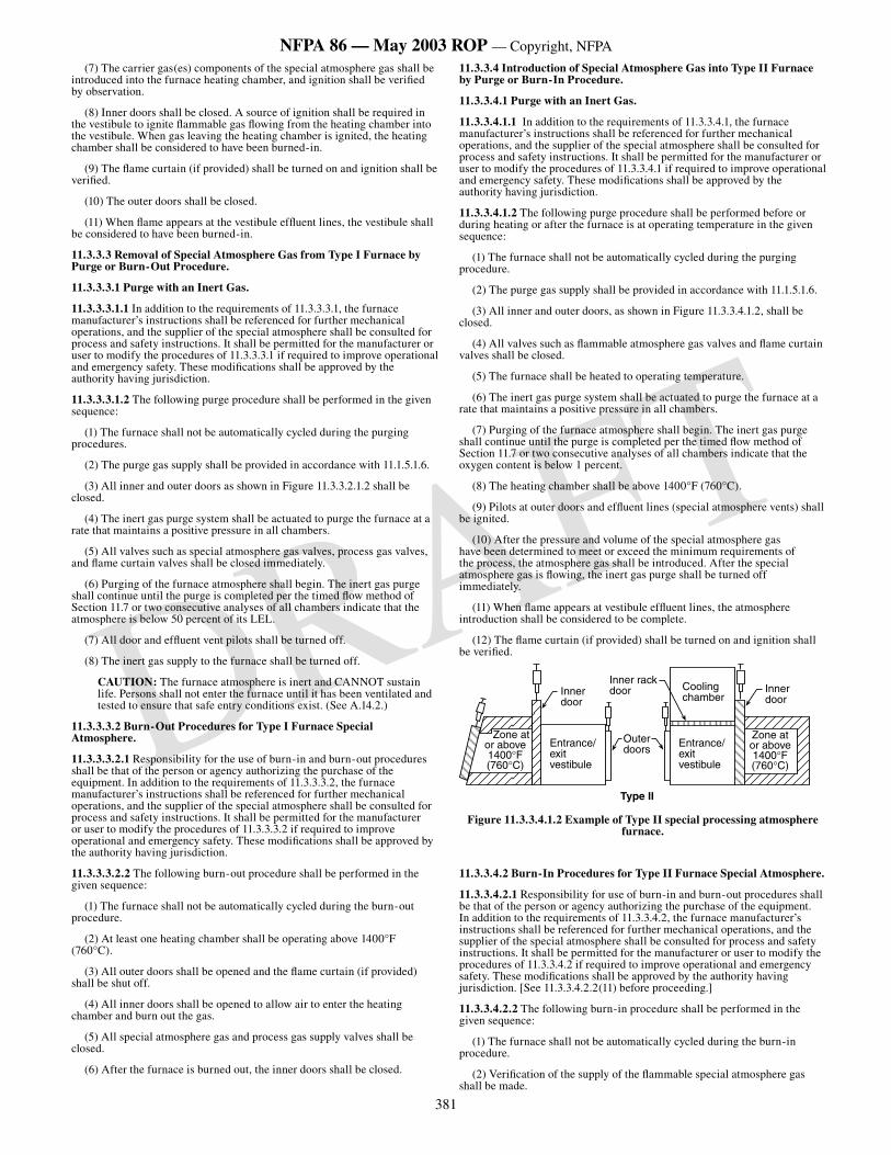
381
NFPA 86 — May 2003 ROP — Copyright, NFPA
DRAFT
(7) The carrier gas(es) components of the special atmosphere gas shall be introduced into the furnace heating chamber, and ignition shall be verified by observation.
(8) Inner doors shall be closed. A source of ignition shall be required in the vestibule to ignite flammable gas flowing from the heating chamber into the vestibule. When gas leaving the heating chamber is ignited, the heating chamber shall be considered to have been burned-in.
(9) The flame curtain (if provided) shall be turned on and ignition shall be verified.
(10) The outer doors shall be closed.
(11) When flame appears at the vestibule effluent lines, the vestibule shall be considered to have been burned-in.
11.3.3.3 Removal of Special Atmosphere Gas from Type I Furnace by Purge or Burn-Out Procedure.
11.3.3.3.1 Purge with an Inert Gas.
11.3.3.3.1.1 In addition to the requirements of 11.3.3.3.1, the furnace manufacturer’s instructions shall be referenced for further mechanical operations, and the supplier of the special atmosphere shall be consulted for process and safety instructions. It shall be permitted for the manufacturer or user to modify the procedures of 11.3.3.3.1 if required to improve operational and emergency safety. These modifications shall be approved by the authority having jurisdiction.
11.3.3.3.1.2 The following purge procedure shall be performed in the given sequence:
(1) The furnace shall not be automatically cycled during the purging procedures.
(2) The purge gas supply shall be provided in accordance with 11.1.5.1.6.
(3) All inner and outer doors as shown in Figure 11.3.3.2.1.2 shall be closed.
(4) The inert gas purge system shall be actuated to purge the furnace at a rate that maintains a positive pressure in all chambers.
(5) All valves such as special atmosphere gas valves, process gas valves, and flame curtain valves shall be closed immediately.
(6) Purging of the furnace atmosphere shall begin. The inert gas purge shall continue until the purge is completed per the timed flow method of Section 11.7 or two consecutive analyses of all chambers indicate that the atmosphere is below 50 percent of its LEL.
(7) All door and effluent vent pilots shall be turned off.
(8) The inert gas supply to the furnace shall be turned off.
CAUTION: The furnace atmosphere is inert and CANNOT sustain life. Persons shall not enter the furnace until it has been ventilated and tested to ensure that safe entry conditions exist. (See A.14.2.)
11.3.3.3.2 Burn-Out Procedures for Type I Furnace Special Atmosphere.
11.3.3.3.2.1 Responsibility for the use of burn-in and burn-out procedures shall be that of the person or agency authorizing the purchase of the equipment. In addition to the requirements of 11.3.3.3.2, the furnace manufacturer’s instructions shall be referenced for further mechanical operations, and the supplier of the special atmosphere shall be consulted for process and safety instructions. It shall be permitted for the manufacturer or user to modify the procedures of 11.3.3.3.2 if required to improve operational and emergency safety. These modifications shall be approved by the authority having jurisdiction.
11.3.3.3.2.2 The following burn-out procedure shall be performed in the given sequence:
(1) The furnace shall not be automatically cycled during the burn-out procedure.
(2) At least one heating chamber shall be operating above 1400°F (760°C).
(3) All outer doors shall be opened and the flame curtain (if provided) shall be shut off.
(4) All inner doors shall be opened to allow air to enter the heating chamber and burn out the gas.
(5) All special atmosphere gas and process gas supply valves shall be closed.
(6) After the furnace is burned out, the inner doors shall be closed.
11.3.3.4 Introduction of Special Atmosphere Gas into Type II Furnace by Purge or Burn-In Procedure.
11.3.3.4.1 Purge with an Inert Gas.
11.3.3.4.1.1 In addition to the requirements of 11.3.3.4.1, the furnace manufacturer’s instructions shall be referenced for further mechanical operations, and the supplier of the special atmosphere shall be consulted for process and safety instructions. It shall be permitted for the manufacturer or user to modify the procedures of 11.3.3.4.1 if required to improve operational and emergency safety. These modifications shall be approved by the authority having jurisdiction.
11.3.3.4.1.2 The following purge procedure shall be performed before or during heating or after the furnace is at operating temperature in the given sequence:
(1) The furnace shall not be automatically cycled during the purging procedure.
(2) The purge gas supply shall be provided in accordance with 11.1.5.1.6.
(3) All inner and outer doors, as shown in Figure 11.3.3.4.1.2, shall be closed.
(4) All valves such as flammable atmosphere gas valves and flame curtain valves shall be closed.
(5) The furnace shall be heated to operating temperature.
(6) The inert gas purge system shall be actuated to purge the furnace at a rate that maintains a positive pressure in all chambers.
(7) Purging of the furnace atmosphere shall begin. The inert gas purge shall continue until the purge is completed per the timed flow method of Section 11.7 or two consecutive analyses of all chambers indicate that the oxygen content is below 1 percent.
(8) The heating chamber shall be above 1400°F (760°C).
(9) Pilots at outer doors and effluent lines (special atmosphere vents) shall be ignited.
(10) After the pressure and volume of the special atmosphere gas have been determined to meet or exceed the minimum requirements of the process, the atmosphere gas shall be introduced. After the special atmosphere gas is flowing, the inert gas purge shall be turned off immediately.
(11) When flame appears at vestibule effluent lines, the atmosphere introduction shall be considered to be complete.
(12) The flame curtain (if provided) shall be turned on and ignition shall be verified.
Zone ator above 1400°F(760°C)
Entrance/ exit vestibule
Inner door
Inner rackdoor
Outer doors
Entrance/ exit vestibule
Zone at or above 1400°F(760°C)
Cooling chamber
Inner door
Type II
Figure 11.3.3.4.1.2 Example of Type II special processing atmosphere furnace.
11.3.3.4.2 Burn-In Procedures for Type II Furnace Special Atmosphere.
11.3.3.4.2.1 Responsibility for use of burn-in and burn-out procedures shall be that of the person or agency authorizing the purchase of the equipment. In addition to the requirements of 11.3.3.4.2, the furnace manufacturer’s instructions shall be referenced for further mechanical operations, and the supplier of the special atmosphere shall be consulted for process and safety instructions. It shall be permitted for the manufacturer or user to modify the procedures of 11.3.3.4.2 if required to improve operational and emergency safety. These modifications shall be approved by the authority having jurisdiction. [See 11.3.3.4.2.2(11) before proceeding.]
11.3.3.4.2.2 The following burn-in procedure shall be performed in the given sequence:
(1) The furnace shall not be automatically cycled during the burn-in procedure.
(2) Verification of the supply of the flammable special atmosphere gas shall be made.
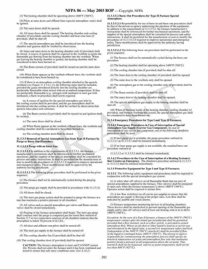
382
NFPA 86 — May 2003 ROP — Copyright, NFPA
DRAFT
(3) The heating chamber shall be operating above 1400°F (760°C).
(4) Pilots at outer doors and effluent lines (special atmosphere vents) shall be ignited.
(5) The outer doors shall be opened.
(6) All inner doors shall be opened. The heating chamber and cooling chamber (if provided), and the cooling chamber and heat zone fans (if provided), shall be shut off.
(7) The special atmosphere gas shall be introduced into the heating chamber and ignition shall be verified by observation.
(8) Inner and outer doors to the heating chamber only (if provided) shall be closed. A source of ignition shall be required in the vestibule to ignite the flammable gas flowing from the heating chamber into the vestibule. When gas leaving the heating chamber is ignited, the heating chamber shall be considered to have been burned-in.
(9) The flame curtain (if provided) shall be turned on and the outer door closed.
(10) When flame appears at the vestibule effluent lines, the vestibule shall be considered to have been burned-in.
(11) If there is an atmosphere cooling chamber attached to the quench vestibule (see Figure 11.3.3.4.1.2), the following steps shall be included, provided the gases introduced directly into the cooling chamber are predictably flammable when mixed with air at ambient temperature. If they are predictably flammable (e.g., nitrogen with methanol or inert gas with methanol), a burn-in procedure shall not be required.
(a) A source of ignition for the special atmosphere gas inlet in the cooling section shall be provided, and the gas atmosphere shall be introduced into the cooling section. It shall be verified by observation that ignition takes place and continues.
(b) The flame curtain (if provided) shall be turned on and ignition shall be verified.
(c) The outer doors shall be closed.
(d) When flame appears at the vestibule effluent lines, the vestibule and cooling chamber shall be considered to have been burned-in.
(e) The cooling chamber door shall be closed.
11.3.3.5 Removal of Special Atmosphere Gas from Type II Furnace by Purge or Burn-Out Procedure.
11.3.3.5.1 Purge with an Inert Gas.
11.3.3.5.1.1 In addition to the requirements of 11.3.3.5.1, the furnace manufacturer’s instructions shall be referenced for further mechanical operations, and the supplier of the special atmosphere shall be consulted for process and safety instructions. It shall be permitted for the manufacturer or user to modify the procedures of 11.3.3.5.1 if required to improve operational and emergency safety. These modifications shall be approved by the authority having jurisdiction.
11.3.3.5.1.2 The following purge procedure shall be performed in the given sequence:
(1) The furnace shall not be automatically cycled during the purging procedure.
(2) The purge gas supply shall be provided in accordance with 11.1.5.1.6.
(3) All doors shall be closed.
(4) The inert gas purge system shall be actuated to purge the furnace at a rate that maintains a positive pressure in all chambers.
(5) All valves such as special atmosphere gas valves and flame curtain valves shall be closed immediately.
(6) Purging of the furnace atmosphere shall begin. The inert gas purge shall continue until the purge is completed per the timed flow method of Section 11.7 or two consecutive analyses of all chambers indicate that the atmosphere is below 50 percent of its LEL.
(7) All door and effluent vent pilots shall be turned off.
(8) The inert gas supply to the furnace shall be turned off.
(9) The cooling chamber fan (if provided) shall be shut off.
(10) The cooling chamber door (if provided) shall be opened.
CAUTION: The furnace atmosphere is inert and CANNOT sustain life. Persons shall not enter the furnace until it has been ventilated and tested to ensure that safe entry conditions exist. (See A.14.2.)
11.3.3.5.2 Burn-Out Procedures for Type II Furnace Special Atmosphere.
11.3.3.5.2.1 Responsibility for use of burn-in and burn-out procedures shall be that of the person or agency authorizing the purchase of the equipment. In addition to the requirements of 11.3.3.5.2, the furnace manufacturer’s instructions shall be referenced for further mechanical operations, and the supplier of the special atmosphere shall be consulted for process and safety instructions. It shall be permitted for the manufacturer or user to modify the procedures of 11.3.3.5.2 if required to improve operational and emergency safety. These modifications shall be approved by the authority having jurisdiction.
11.3.3.5.2.2 The following burn-out procedure shall be performed in the given sequence:
(1) The furnace shall not be automatically cycled during the burn-out procedure.
(2) The heating chamber shall be operating above 1400°F (760°C).
(3) The cooling chamber fan (if provided) shall be shut off.
(4) The inner door to the cooling chamber (if provided) shall be opened.
(5) The outer door to the vestibule only shall be opened.
(6) The atmosphere gas to the cooling chamber only (if provided) shall be shut off.
(7) The flame curtain (if provided) shall be shut off.
(8) The inner door to the heating chamber shall be opened.
(9) The special atmosphere gas supply to the heating chamber shall be shut off.
(10) When all burning inside of the heating chamber, cooling chamber (if provided), and furnace vestibule has ceased, the special atmosphere gas shall be considered to have been burned out.
11.3.4 Emergency Procedures for Type I and Type II Furnaces.
11.3.4.1 Emergency Procedures in Case of Interruption of Special Atmosphere Gas Supply (Carrier Gas Component). In case of interruption of any carrier gas component, one of the following shutdown procedures shall be used:
(1) If inert purge gas is available, the purge procedure outlined in 11.3.3.3.1 or 11.3.3.5.1 shall be initiated immediately.
(2) If an inert purge gas supply is not available, the standard burn-out procedure outlined in
11.3.3.3.2 or 11.3.3.5.2 shall be initiated immediately.
11.3.4.2 Procedures in the Case of Interruption of a Heating System(s) that Creates an Emergency. The shutdown procedure outlined in 11.3.3.3 or 11.3.3.5 shall be initiated immediately.
11.3.5 Protective Equipment for Type I and Type II Furnaces.
11.3.5.1 The following safety equipment and procedures shall be required in conjunction with the special atmosphere gas system:
(1) A safety shut-off valve(s) on all flammable fluids that are part of special atmospheres supplied to the furnace. This valve(s) shall be energized to open only when the furnace temperature is above 1400°F (760°C). Operator action shall be required to initiate flow.
(2) A low flow switch(es) on all carrier gas supplies to ensure that the atmosphere gas supply is flowing at the proper rates. Low flow shall be indicated by audible and visual alarms.
(3) Furnace temperature monitoring devices in all heating chambers. These devices shall be interlocked to prevent opening of the flammable gas supply safety shut-off valve(s) until at least one heating zone is at or above 1400°F (760°C).
Exception: In the case of a Type II furnace, a bypass of the 1400°F (760°C) temperature contact after the initial gas introduction shall be permitted, provided that a flow monitor, such as a flow switch, is provided to ensure atmosphere flow. Where an alcohol or other liquid is used as a carrier gas and introduced in the liquid state, a second low temperature safety interlock [independent of the 1400°F (760°C) interlock] shall be provided if flow of the liquid is continued below 1400°F (760°C). The person or agency responsible for commissioning the atmosphere process shall specify an interlock temperature set point and atmosphere flow rate that maintains positive furnace pressure at all temperatures above the set point. This interlock shall not be bypassed, and its set point temperature shall not be less than 800°F (427°C).
383
NFPA 86 — May 2003 ROP — Copyright, NFPA
DRAFT
(4) The inert gas purge automatically actuated by the following:
(a) A temperature less than 800°F (427°C) where liquid carrier gas is used
(b) Power failure
(c) Loss of flow of any carrier gas
Exception No. 1: An inert gas purge shall not be required where burn-in and burn-out procedures are permitted by the person or agency authorizing the purchase of the equipment.
Exception No. 2: Manual inert gas purge shall be permitted to be provided for furnaces where operators can effect timely shutdown procedures.
(5) Pilots at outer doors — one pilot at each outer door shall be supervised with an approved combustion safeguard interlocked to prevent automatic opening of the vestibule door, shut off fuel gas to the curtain burners (if provided), and alert the operator. Pilots shall be of the type that remain lit when subjected to an inert or indeterminate atmosphere.
(6) Pilots located at effluents.
(7) Manual shut-off valves and capability for checking leak tightness of the safety shut-off valves.
(8) Safety relief valves where overpressurizing of glass tube flow meters is possible.
(9) Provisions for explosion relief in the vestibule.
(10) Audible and visual alarms.
(11) A safety shut-off valve for the flame curtain burner gas supply.
(12) Valves for manually shutting off the flow of flammable liquids into a furnace that are separate from the atmosphere flow control unit. These valves shall be readily accessible to operators and remotely located from the furnace and control unit.
(13) Manual door-opening facilities to allow operator control in the event of power failure or carrier gas flow failure.
(14)*The purge system, where provided, including the following:
(a) Visual and audible alarms to alert the operator of low purge flow rate
(b) Gas analyzing equipment for ensuring that the furnace is purged
(c) Monitoring devices to allow the operator to determine the rate of the inert purge flow visually at all times
(d) An operator’s actuation station equipped with the necessary hand valves, regulators, relief valves, and flow and pressure monitoring devices
11.3.5.2 All the following protective equipment for furnaces utilizing timed flow purges shall be provided:
(1) Purge timer(s)
(2) Purge gas flow meter(s)
(3) Purge flow monitoring device(s)
(4) Fan rotation sensor(s)
11.4 Furnace Types III, IV, and V.
11.4.1 General.
11.4.1.1 Scope. This section shall apply to controls and procedures relating to the introduction and removal of flammable special processing atmospheres. The following three general types of furnaces are covered:
(1) Type III — Both inlet and outlet ends of the furnace are open, and there are no external doors or covers
(2) Type IV — One end only is open
(3) Type V — Outer doors or covers are provided
11.4.1.2 Special Atmosphere Flow Requirements.
11.4.1.2.1 Atmosphere processes and the equipment for controlling the flows of special atmospheres shall be installed and operated to minimize the infiltration of air into a furnace, which could result in the creation of flammable gas–air mixtures within the furnace.
11.4.1.2.2* The special atmosphere flow rate shall maintain stable burning of the atmosphere as it exits the furnace. The person or agency commissioning the furnace or atmosphere process shall prescribe a flow rate.
11.4.1.2.3 The flow rate of an inert gas being used as a purge shall be
controlled. The inert gas shall be introduced to the furnaces through one or more inlets as necessary to ensure that all chambers are purged.
11.4.2 Atmosphere Introduction and Removal.
11.4.2.1 Flammable liquids shall be introduced only in zones operating above 1400°F (760°C).
11.4.2.2 Introduction of Special Atmosphere Gas into Type III Furnace by Purge or Burn-In Procedure.
11.4.2.2.1 Purge with an Inert Gas.
11.4.2.2.1.1 In addition to the requirements of 11.4.2.2.1, the furnace manufacturer’s instructions shall be referenced for further mechanical operations, and the supplier of the special atmosphere shall be consulted for process and safety instructions. It shall be permitted for the manufacturer or user to modify the procedures of 11.4.2.2.1 if required to improve operational and emergency safety. These modifications shall be approved by the authority having jurisdiction.
11.4.2.2.1.2 The following purge procedure shall be performed in the given sequence before or during heating or after the furnace is at operating temperature.
(1) The furnace shall not be automatically cycled during the purging procedure.
(2) The purge gas supply shall be provided in accordance with 11.1.5.1.6.
(3) All valves such as flammable atmosphere gas valves and flame curtain valves shall be closed.
(4) The furnace shall be heated to operating temperature.
(5) The inert gas purge system shall be actuated to purge the furnace at a rate that maintains a positive pressure in all chambers.
(6) Purging of the furnace atmosphere shall begin. The inert gas purge shall continue until the purge is completed per the timed flow method of Section 11.7 or two consecutive analyses of all chambers indicate that the oxygen content is below 1 percent.
(7) At least one zone of the furnace shall be above 1400°F (760°C). (See Figure 11.4.2.2.1.2.)
(8) Pilots at charge and discharge ends of the furnace shall be ignited.
(9) After the pressure and volume of the special atmosphere gas supply have been determined to meet or exceed the minimum requirements of the process, the atmosphere gas shall be introduced. After the special atmosphere gas is flowing, the inert gas purge shall be turned off immediately.
(10) When flame appears at both the charge and discharge ends of the furnace, the atmosphere introduction shall be considered to be complete.
(11) The flame curtain (if provided) shall be turned on and ignition shall be verified.
Open
At least one zone ator above 1400°F (760°C) Open
At least onezone at or above 1400°F (760°C)Open Open
Less than 1400°F (760°C)
Type III
Figure 11.4.2.2.1.2 Examples of Type III special processing atmosphere furnace.
11.4.2.2.2 Burn-In Procedures for Type III Furnace Special Atmosphere.
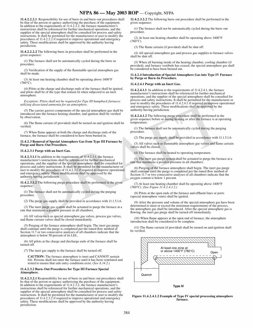
384
NFPA 86 — May 2003 ROP — Copyright, NFPA
DRAFT
11.4.2.2.2.1 Responsibility for use of burn-in and burn-out procedures shall be that of the person or agency authorizing the purchase of the equipment. In addition to the requirements of 11.4.2.2.2, the furnace manufacturer’s instructions shall be referenced for further mechanical operations, and the supplier of the special atmosphere shall be consulted for process and safety instructions. It shall be permitted for the manufacturer or user to modify the procedures of 11.4.2.2.2 if required to improve operational and emergency safety. These modifications shall be approved by the authority having jurisdiction.
11.4.2.2.2.2 The following burn-in procedure shall be performed in the given sequence:
(1) The furnace shall not be automatically cycled during the burn-in procedure.
(2) Verification of the supply of the flammable special atmosphere gas shall be made.
(3) At least one heating chamber shall be operating above 1400°F (760°C).
(4) Pilots at the charge and discharge ends of the furnace shall be ignited, and pilots shall be of the type that remain lit when subjected to an inert atmosphere.
Exception: Pilots shall not be required for Type III humpback furnaces utilizing dissociated ammonia for an atmosphere.
(5) The carrier gas(es) components of the special atmosphere gas shall be introduced into the furnace heating chamber, and ignition shall be verified by observation.
(6) The flame curtain (if provided) shall be turned on and ignition shall be verified.
(7) When flame appears at both the charge and discharge ends of the furnace, the furnace shall be considered to have been burned in.
11.4.2.3 Removal of Special Atmosphere Gas from Type III Furnace by Purge and Burn-Out Procedure.
11.4.2.3.1 Purge with an Inert Gas.
11.4.2.3.1.1 In addition to the requirements of 11.4.2.3.1, the furnace manufacturer’s instructions shall be referenced for further mechanical operations, and the supplier of the special atmosphere shall be consulted for process and safety instructions. It shall be permitted for the manufacturer or user to modify the procedures of 11.4.2.3.1 if required to improve operational and emergency safety. These modifications shall be approved by the authority having jurisdiction.
11.4.2.3.1.2 The following purge procedure shall be performed in the given sequence:
(1) The furnace shall not be automatically cycled during the purging procedure.
(2) The purge gas supply shall be provided in accordance with 11.1.5.1.6.
(3) The inert purge gas system shall be actuated to purge the furnace at a rate that maintains a positive pressure in all chambers.
(4) All valves such as special atmosphere gas valves, process gas valves, and flame curtain valves shall be closed immediately.
(5) Purging of the furnace atmosphere shall begin. The inert gas purge shall continue until the purge is completed per the timed flow method of Section 11.7 or two consecutive analyses of all chambers indicate that the atmosphere is below 50 percent of its LEL.
(6) All pilots at the charge and discharge ends of the furnace shall be turned off.
(7) The inert gas supply to the furnace shall be turned off.
CAUTION: The furnace atmosphere is inert and CANNOT sustain life. Persons shall not enter the furnace until it has been ventilated and tested to ensure that safe entry conditions exist. (See A.14.2.)
11.4.2.3.2 Burn-Out Procedures for Type III Furnace Special Atmosphere.
11.4.2.3.2.1 Responsibility for use of burn-in and burn-out procedures shall be that of the person or agency authorizing the purchase of the equipment. In addition to the requirements of 11.4.2.3.2, the furnace manufacturer’s instructions shall be referenced for further mechanical operations, and the supplier of the special atmosphere shall be consulted for process and safety instructions. It shall be permitted for the manufacturer or user to modify the procedures of 11.4.2.3.2 if required to improve operational and emergency safety. These modifications shall be approved by the authority having jurisdiction.
11.4.2.3.2.2 The following burn-out procedure shall be performed in the given sequence:
(1) The furnace shall not be automatically cycled during the burn-out procedure.
(2) At least one heating chamber shall be operating above 1400°F (760°C).
(3) The flame curtain (if provided) shall be shut off.
(4) All special atmosphere gas and process gas supplies to furnace valves shall be shut off.
(5) When all burning inside of the heating chamber, cooling chamber (if provided), and furnace vestibule has ceased, the special atmosphere gas shall be considered to have been burned out.
11.4.2.4 Introduction of Special Atmosphere Gas into Type IV Furnace by Purge or Burn-In Procedure.
11.4.2.4.1 Purge with an Inert Gas.
11.4.2.4.1.1 In addition to the requirements of 11.4.2.4.1, the furnace manufacturer’s instructions shall be referenced for further mechanical operations, and the supplier of the special atmosphere shall be consulted for process and safety instructions. It shall be permitted for the manufacturer or user to modify the procedures of 11.4.2.4.1 if required to improve operational and emergency safety. These modifications shall be approved by the authority having jurisdiction.
11.4.2.4.1.2 The following purge procedure shall be performed in the given sequence before or during heating or after the furnace is at operating temperature:
(1) The furnace shall not be automatically cycled during the purging procedure.
(2) The purge gas supply shall be provided in accordance with 11.1.5.1.6.
(3) All valves such as flammable atmosphere gas valves and flame curtain valves shall be closed.
(4) The furnace shall be heated to operating temperature.
(5) The inert gas purge system shall be actuated to purge the furnace at a rate that maintains a positive pressure in all chambers.
(6) Purging of the furnace atmosphere shall begin. The inert gas purge shall continue until the purge is completed per the timed flow method of Section 11.7 or two consecutive analyses of all chambers indicate that the oxygen content is below 1 percent.
(7) At least one heating chamber shall be operating above 1400°F (760°C). (See Figure 11.4.2.4.1.2.)
(8) Pilots at the open ends of the furnace and effluent lines or ports (special atmosphere vents) shall be ignited.
(9) After the pressure and volume of the special atmosphere gas have been determined to meet or exceed the minimum requirements of the process, the atmosphere gas shall be introduced. After the special atmosphere gas is flowing, the inert gas purge shall be turned off immediately.
(10) When flame appears at the open end of furnace, the atmosphere introduction shall be considered to be complete.
(11) The flame curtain (if provided) shall be turned on and ignition shall be verified.
At least one zone ator above 1400°F (760°C) Open
Quench
Type IV
Figure 11.4.2.4.1.2 Example of Type IV special processing atmosphere furnace.
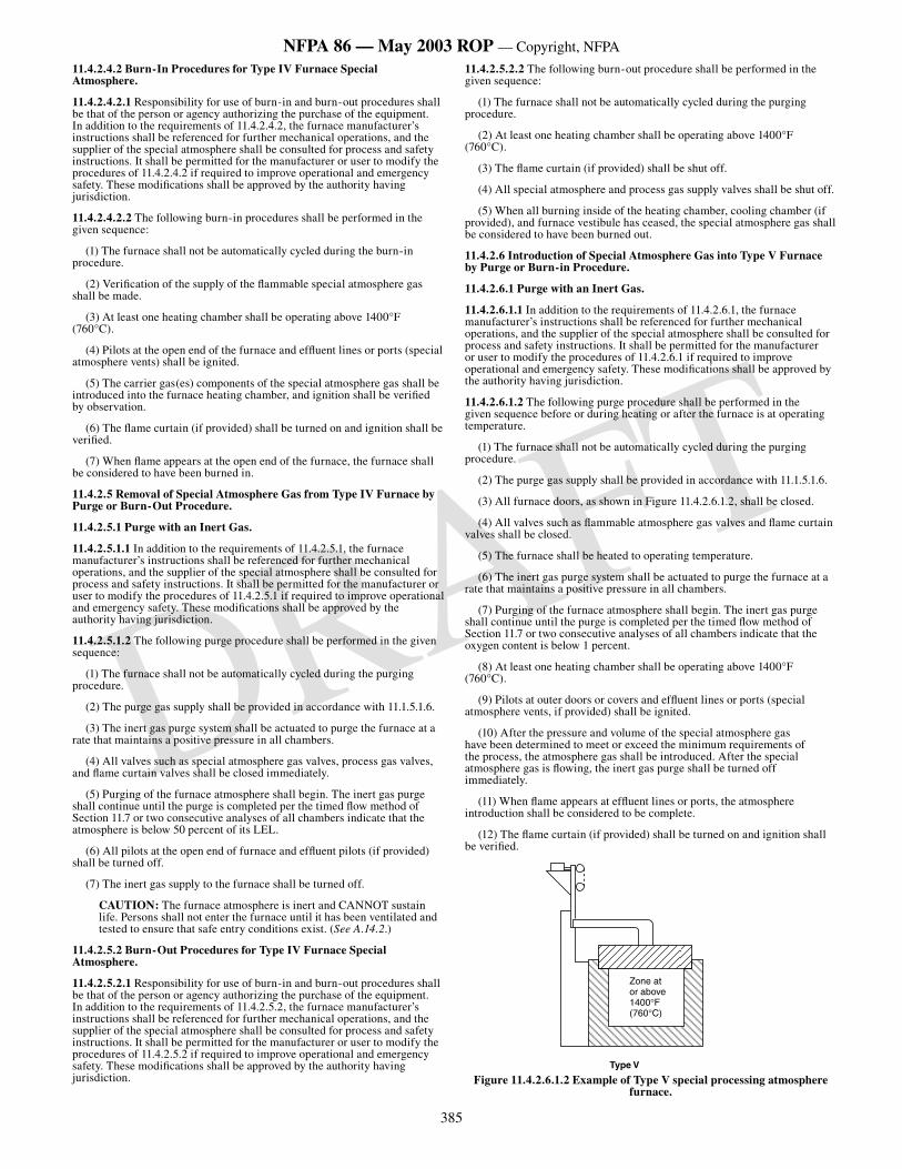
385
NFPA 86 — May 2003 ROP — Copyright, NFPA
DRAFT
11.4.2.4.2 Burn-In Procedures for Type IV Furnace Special Atmosphere.
11.4.2.4.2.1 Responsibility for use of burn-in and burn-out procedures shall be that of the person or agency authorizing the purchase of the equipment. In addition to the requirements of 11.4.2.4.2, the furnace manufacturer’s instructions shall be referenced for further mechanical operations, and the supplier of the special atmosphere shall be consulted for process and safety instructions. It shall be permitted for the manufacturer or user to modify the procedures of 11.4.2.4.2 if required to improve operational and emergency safety. These modifications shall be approved by the authority having jurisdiction.
11.4.2.4.2.2 The following burn-in procedures shall be performed in the given sequence:
(1) The furnace shall not be automatically cycled during the burn-in procedure.
(2) Verification of the supply of the flammable special atmosphere gas shall be made.
(3) At least one heating chamber shall be operating above 1400°F (760°C).
(4) Pilots at the open end of the furnace and effluent lines or ports (special atmosphere vents) shall be ignited.
(5) The carrier gas(es) components of the special atmosphere gas shall be introduced into the furnace heating chamber, and ignition shall be verified by observation.
(6) The flame curtain (if provided) shall be turned on and ignition shall be verified.
(7) When flame appears at the open end of the furnace, the furnace shall be considered to have been burned in.
11.4.2.5 Removal of Special Atmosphere Gas from Type IV Furnace by Purge or Burn-Out Procedure.
11.4.2.5.1 Purge with an Inert Gas.
11.4.2.5.1.1 In addition to the requirements of 11.4.2.5.1, the furnace manufacturer’s instructions shall be referenced for further mechanical operations, and the supplier of the special atmosphere shall be consulted for process and safety instructions. It shall be permitted for the manufacturer or user to modify the procedures of 11.4.2.5.1 if required to improve operational and emergency safety. These modifications shall be approved by the authority having jurisdiction.
11.4.2.5.1.2 The following purge procedure shall be performed in the given sequence:
(1) The furnace shall not be automatically cycled during the purging procedure.
(2) The purge gas supply shall be provided in accordance with 11.1.5.1.6.
(3) The inert gas purge system shall be actuated to purge the furnace at a rate that maintains a positive pressure in all chambers.
(4) All valves such as special atmosphere gas valves, process gas valves, and flame curtain valves shall be closed immediately.
(5) Purging of the furnace atmosphere shall begin. The inert gas purge shall continue until the purge is completed per the timed flow method of Section 11.7 or two consecutive analyses of all chambers indicate that the atmosphere is below 50 percent of its LEL.
(6) All pilots at the open end of furnace and effluent pilots (if provided) shall be turned off.
(7) The inert gas supply to the furnace shall be turned off.
CAUTION: The furnace atmosphere is inert and CANNOT sustain life. Persons shall not enter the furnace until it has been ventilated and tested to ensure that safe entry conditions exist. (See A.14.2.)
11.4.2.5.2 Burn-Out Procedures for Type IV Furnace Special Atmosphere.
11.4.2.5.2.1 Responsibility for use of burn-in and burn-out procedures shall be that of the person or agency authorizing the purchase of the equipment. In addition to the requirements of 11.4.2.5.2, the furnace manufacturer’s instructions shall be referenced for further mechanical operations, and the supplier of the special atmosphere shall be consulted for process and safety instructions. It shall be permitted for the manufacturer or user to modify the procedures of 11.4.2.5.2 if required to improve operational and emergency safety. These modifications shall be approved by the authority having jurisdiction.
11.4.2.5.2.2 The following burn-out procedure shall be performed in the given sequence:
(1) The furnace shall not be automatically cycled during the purging procedure.
(2) At least one heating chamber shall be operating above 1400°F (760°C).
(3) The flame curtain (if provided) shall be shut off.
(4) All special atmosphere and process gas supply valves shall be shut off.
(5) When all burning inside of the heating chamber, cooling chamber (if provided), and furnace vestibule has ceased, the special atmosphere gas shall be considered to have been burned out.
11.4.2.6 Introduction of Special Atmosphere Gas into Type V Furnace by Purge or Burn-in Procedure.
11.4.2.6.1 Purge with an Inert Gas.
11.4.2.6.1.1 In addition to the requirements of 11.4.2.6.1, the furnace manufacturer’s instructions shall be referenced for further mechanical operations, and the supplier of the special atmosphere shall be consulted for process and safety instructions. It shall be permitted for the manufacturer or user to modify the procedures of 11.4.2.6.1 if required to improve operational and emergency safety. These modifications shall be approved by the authority having jurisdiction.
11.4.2.6.1.2 The following purge procedure shall be performed in the given sequence before or during heating or after the furnace is at operating temperature.
(1) The furnace shall not be automatically cycled during the purging procedure.
(2) The purge gas supply shall be provided in accordance with 11.1.5.1.6.
(3) All furnace doors, as shown in Figure 11.4.2.6.1.2, shall be closed.
(4) All valves such as flammable atmosphere gas valves and flame curtain valves shall be closed.
(5) The furnace shall be heated to operating temperature.
(6) The inert gas purge system shall be actuated to purge the furnace at a rate that maintains a positive pressure in all chambers.
(7) Purging of the furnace atmosphere shall begin. The inert gas purge shall continue until the purge is completed per the timed flow method of Section 11.7 or two consecutive analyses of all chambers indicate that the oxygen content is below 1 percent.
(8) At least one heating chamber shall be operating above 1400°F (760°C).
(9) Pilots at outer doors or covers and effluent lines or ports (special atmosphere vents, if provided) shall be ignited.
(10) After the pressure and volume of the special atmosphere gas have been determined to meet or exceed the minimum requirements of the process, the atmosphere gas shall be introduced. After the special atmosphere gas is flowing, the inert gas purge shall be turned off immediately.
(11) When flame appears at effluent lines or ports, the atmosphere introduction shall be considered to be complete.
(12) The flame curtain (if provided) shall be turned on and ignition shall be verified.
Zone at or above 1400°F(760°C)
Type V
Figure 11.4.2.6.1.2 Example of Type V special processing atmosphere furnace.
386
NFPA 86 — May 2003 ROP — Copyright, NFPA
DRAFT
11.4.2.6.2 Burn-In Procedures for Type V Furnace Special Atmosphere.
11.4.2.6.2.1 Responsibility for use of burn-in and burn-out procedures shall be that of the person or agency authorizing the purchase of the equipment. In addition to the requirements of 11.4.2.6.2, the furnace manufacturer’s instructions shall be referenced for further mechanical operations, and the supplier of the special atmosphere shall be consulted for process and safety instructions. It shall be permitted for the manufacturer or user to modify the procedures of 11.4.2.6.2 if required to improve operational and emergency safety. These modifications shall be approved by the authority having jurisdiction.
11.4.2.6.1.2 The following burn-in procedure shall be performed in the given sequence:
(1) The furnace shall not be automatically cycled during the burn-in procedure.
(2) Verification of the supply of the special atmosphere gas shall be made.
(3) At least one heating chamber shall be operating above 1400°F (760°C).
(4) Pilots at outer doors or covers and effluent lines or ports (special atmosphere vents, if provided) shall be ignited.
(5) The outer doors shall be opened.
(6) The carrier gas(es) components of the special atmosphere gas shall be introduced into the furnace heating chamber and ignition shall be verified by observation.
(7) The flame curtain (if provided) shall be turned on.
(8) The outer doors shall be closed.
(9) When flame appears at effluent lines or ports, the furnace shall be considered to have been burned in.
11.4.2.7 Removal of Special Atmosphere Gas from Type V Furnace by Purge or Burn-Out Procedure.
11.4.2.7.1 Purge with an Inert Gas.
11.4.2.7.1.1 In addition to the requirements of 11.4.2.7.1, the furnace manufacturer’s instructions shall be referenced for further mechanical operations, and the supplier of the special atmosphere shall be consulted for process and safety instructions. It shall be permitted for the manufacturer or user to modify the procedures of 11.4.2.7.1 if required to improve operational and emergency safety. These modifications shall be approved by the authority having jurisdiction.
11.4.2.7.1.2 The following purge procedure shall be performed in the given sequence:
(1) The furnace shall not be automatically cycled during the purging procedure.
(2) The purge gas supply shall be provided in accordance with 11.1.5.1.6.
(3) All doors shall be closed.
(4) The inert gas purge system shall be actuated to purge the furnace at a rate that maintains a positive pressure in all chambers.
(5) All valves such as special atmosphere gas valves, process gas valves, and flame curtain valves shall be closed immediately.
(6) Purging of the furnace atmosphere shall begin. The inert gas purge shall continue until the purge is completed per the timed flow method of Section 11.7 or two consecutive analyses of all chambers indicate that the atmosphere is below 50 percent of its LEL.
(7) All door, cover, and effluent pilots (if provided) shall be turned off.
(8) The inert gas supply to the furnace shall be turned off.
CAUTION: The furnace atmosphere is inert and CANNOT sustain life. Persons shall not enter the furnace until it has been ventilated and tested to ensure that safe entry conditions exist. (See A.14.2.)
11.4.2.7.2 Burn-Out Procedures for Type V Furnace Special Atmosphere.
11.4.2.7.2.1 Responsibility for use of burn-in and burn-out procedures shall be that of the person or agency authorizing the purchase of the equipment. In addition to the requirements of 11.4.2.7.2, the furnace manufacturer’s instructions shall be referenced for further mechanical operations, and the supplier of the special atmosphere shall be consulted for process and safety instructions. It shall be permitted for the manufacturer or user to modify the procedures of 11.4.2.7.2 if required to improve operational and emergency safety. These modifications shall be approved by the authority having jurisdiction.
11.4.2.7.2.2 The following burn-out procedure shall be performed in the given sequence:
(1) The furnace shall not be automatically cycled during the burn-out procedure.
(2) At least one heating chamber shall be operating above 1400°F (760°C).
(3) All doors or covers shall be opened to allow air to enter the furnace and burn out the special atmosphere.
(4) The flame curtain (if provided) shall be shut off.
(5) All special atmosphere and process gas supply valves shall be shut off.
(6) When all burning inside of the heating chamber, cooling chamber (if provided), and furnace vestibule has ceased, the special atmosphere gas shall be considered to have been burned out.
11.4.3 Emergency Procedures for Types III, IV, and V Furnaces.
11.4.3.1 Emergency Procedures in Case of Interruption of Special Atmosphere Gas Supply (Carrier Gas Component). In case of interruption of any carrier gas component, one of the following shutdown procedures shall be used:
(1) If inert purge gas is available, the purge procedure outlined in 11.4.2.3.1, 11.4.2.5.1, or 11.4.2.7.1 shall be initiated immediately.
(2) If inert purge gas supply is not available, the standard burn-out procedure outlined in 11.4.2.3.2, 11.4.2.5.2, or 11.4.2.7.2 shall be initiated immediately.
11.4.3.2 Procedures in the Case of Interruption of a Heating System(s) that Creates an Emergency. The shutdown procedure outlined in 11.4.2.3 or 11.4.2.5 shall be initiated immediately.
11.4.4 Protective Equipment for Types III, IV, and V Furnaces.
11.4.4.1 The following safety equipment and procedures shall be required in conjunction with the special atmosphere gas system.
(1) A safety shut-off valve(s) on all flammable fluids that are part of special atmospheres supplied to the furnace. This valve(s) shall be energized to open only when the furnace temperature is above 1400°F (760°C). Operator action shall be required to initiate flow.
(2) A low flow switch(es) on all carrier gas supplies to ensure that the atmosphere gas supply is flowing at the proper rates. Low flow shall be indicated by visual and audible alarms.
(3) Furnace temperature monitoring devices in all heating chambers. These devices shall be interlocked to prevent opening of the flammable gas supply safety shut-off valve(s) until at least one heating zone is at or above 1400°F (760°C). In the case of a Type V furnace, a bypass of the 1400°F (760°C) temperature contact after the initial gas introduction shall be permitted, provided that a flow monitor, such as a flow switch, is provided to ensure atmosphere flow. Where an alcohol or other liquid is used as a carrier gas and introduced in the liquid state, a second low temperature safety interlock [independent of the 1400°F (760°C) interlock] shall be provided if flow of the liquid is continued below 1400°F (760°C). The person or agency responsible for commissioning the atmosphere process shall specify an interlock temperature set point and atmosphere flow rate that provides adequate positive furnace pressure at all temperatures above the set point. This interlock shall not be bypassed, and its set point temperature shall not be less than 800°F (427°C).
(4) A safety shut-off valve for the flame curtain burner gas supply.
(5) Audible and visual alarms.
(6) Manual door-opening facilities to allow operator control in the event of power failure or carrier gas flow failure.
(7) The inert gas purge automatically actuated by a temperature less than 800°F (427°C) where liquid carrier gas is used, or there is a power failure or a loss of flow of any carrier gas. A manual purge shall be permitted where burn-in and burn-out procedures are permitted by the person or agency authorizing the purchase of the equipment. Manual inert gas purge shall only be permitted for furnaces where operators can effect timely shutdown procedures.
(8) Pilots at outer doors — One pilot at each outer door shall be supervised with an approved combustion safeguard interlocked to prevent automatic opening of the vestibule door, shut off fuel gas to the curtain burners (if provided), and alert the operator. Pilots shall be of the type that remain lit when subjected to an inert or indeterminate atmosphere.
(9) Pilots located at effluents.
(10) Manual shut-off valves and capability for checking leak tightness of the safety shut-off valves.
387
NFPA 86 — May 2003 ROP — Copyright, NFPA
DRAFT
(11) Safety relief valves where overpressurizing of glass tube flow meters is possible.
(12) Valves for manually shutting off the flow of flammable liquids into a furnace that are separate from the atmosphere flow control unit. These valves shall be readily accessible to operators and remotely located from the furnace and control unit.
(13)*The purge system, where provided, includes the following:
(a) Audible and visual alarms to alert the operator of low purge flow rate
(b) Gas analyzing equipment for ensuring that the furnace is purged
(c) Monitoring devices to allow the operator to determine the rate of the inert purge flow visually at all times
(d) An operator’s actuation station equipped with the necessary hand valves, regulators, relief valves, and flow and pressure monitoring devices
11.4.4.2 All the following protective equipment for furnaces utilizing timed flow purges shall be provided:
(1) Purge timer(s)
(2) Purge gas flow meter(s)
(3) Purge flow monitoring device(s)
(4) Fan rotation sensor(s)
11.5 Type VI and Type VII Furnaces.
11.5.1 General.
11.5.1.1* Scope. This section shall apply to controls and procedures relating to the introduction and removal of flammable special atmospheres. The following two general types of furnaces are covered.
(1) Type VI — At least one zone can be heated above 1400°F (760°C) before introduction and removal of the flammable special atmosphere gas.
(2) Type VII — No zones can be heated to 1400°F (760°C); therefore, the flammable special atmosphere gas shall be introduced and removed using the inert gas purge procedures.
11.5.1.2 Special Atmosphere Flow Requirements.
11.5.1.2.1 Atmosphere processes and the equipment for controlling the flows of special atmospheres shall be installed and operated to minimize the infiltration of air into a furnace, which could result in the creation of flammable gas–air mixtures within the furnace.
11.5.1.2.2* The special atmosphere flow rate shall maintain stable burning of the atmosphere as it exits the furnace. The person or agency commissioning the furnace or atmosphere process shall prescribe a flow rate.
11.5.1.2.3 The flow rate of an inert gas being used as a purge shall be controlled. The inert gas shall be introduced to the furnaces through one or more inlets as necessary to ensure that all chambers are purged.
11.5.2 Atmosphere Introduction and Removal.
11.5.2.1 Introduction of Special Atmosphere Gas into Type VI Furnace by Purge or Burn-In Procedure.
11.5.2.1.1 Purge with an Inert Gas.
11.5.2.1.1.1 In addition to the requirements of 11.5.2.1.1, the furnace manufacturer’s instructions shall be referenced for further mechanical operations, and the supplier of the special atmosphere shall be consulted for process and safety instructions. It shall be permitted for the manufacturer or user to modify the procedures of 11.5.2.1.1 if required to improve operational and emergency safety. These modifications shall be approved by the authority having jurisdiction.
11.5.2.1.1.2 The following purge procedure shall be performed in the given sequence before or during heating or after the furnace is at operating temperature.
(1) The furnace shall not be automatically cycled during the purging procedure.
(2) The purge gas supply shall be provided in accordance with 11.1.5.1.6.
(3) All furnace doors (if provided) shall be closed.
(4) All valves such as flammable atmosphere gas valves and flame curtain valves shall be closed.
(5) The furnace shall be heated to operating temperature.
(6) The inert gas purge system shall be actuated to purge the furnace at a rate that maintains a positive pressure in all chambers.
(7) Purging of the furnace atmosphere shall begin. The inert gas purge shall continue until the purge is completed per the timed flow method of Section 11.7 or two consecutive analyses of all chambers indicate that the oxygen content is below 1 percent.
(8) At least one zone of the furnace shall be above 1400°F (760°C).
(9) Pilots at outer doors (if provided) and effluent lines (special atmosphere vents) shall be ignited.
(10) After the pressure and volume of the special atmosphere gas have been determined to meet or exceed the minimum requirements of the process, the atmosphere gas shall be introduced. After the special atmosphere gas is flowing, the inert gas purge shall be turned off immediately.
(11) When flame appears at the vestibule effluent lines or ports, the atmosphere introduction shall be considered to be complete.
(12) The flame curtain (if provided) shall be turned on and ignition shall be verified.
11.5.2.1.2 Burn-In Procedures for Type VI Furnace Special Atmosphere.
11.5.2.1.2.1 Responsibility for use of burn-in and burn-out procedures shall be that of the person or agency authorizing the purchase of the equipment. In addition to the requirements of 11.5.2.1.2, the furnace manufacturer’s instructions shall be referenced for further mechanical operations, and the supplier of the special atmosphere shall be consulted for process and safety instructions. It shall be permitted for the manufacturer or user to modify the procedures of 11.5.2.1.2 if required to improve operational and emergency safety. These modifications shall be approved by the authority having jurisdiction.
11.5.2.1.2.2 The following burn-in procedure shall be performed in the given sequence:
(1) The furnace shall not be automatically cycled during the burn-in procedure.
(2) Verification of the supply of the special atmosphere gas shall be made.
(3) The purge gas supply shall be provided in accordance with 11.1.5.1.6.
(4) At least one heating chamber shall be operating above 1400°F (760°C).
(5) Pilots at the outer doors (if provided) and effluent lines (special atmosphere vents, if provided) shall be ignited.
(6) The outer doors (if provided) shall be opened.
(7) The inner doors (if provided) shall be opened.
(8) The carrier gas(es) components of the special atmosphere gas shall be introduced into the furnace heating chamber, and ignition shall be verified by observation.
(9) The inner doors (if provided) shall be closed. A source of ignition shall be required in the vestibule to ignite flammable gas flowing from the heating chamber into the vestibule. When gas leaving the heating chamber is ignited, the heating chamber shall be considered to have been burned in.
(10) The flame curtain (if provided) shall be turned on, and ignition shall be verified.
(11) The outer doors (if provided) shall be closed.
(12) When flame appears at the vestibule effluent lines or ports, the vestibule shall be considered to be burned in.
11.5.2.2 Removal of Special Atmosphere Gas from Type VI Furnace by Purge or Burn-Out Procedures.
11.5.2.2.1 Purge with an Inert Gas.
11.5.2.2.1.1 In addition to the requirements of 11.5.2.2.1, the furnace manufacturer’s instructions shall be referenced for further mechanical operations, and the supplier of the special atmosphere shall be consulted for process and safety instructions. It shall be permitted for the manufacturer or user to modify the procedures of 11.5.2.2.1 if required to improve operational and emergency safety. These modifications shall be approved by the authority having jurisdiction.
11.5.2.2.1.2 The following purge procedure shall be performed in the given sequence.
(1) The furnace shall not be automatically cycled during the purging procedure.
388
NFPA 86 — May 2003 ROP — Copyright, NFPA
DRAFT
(2) The purge gas supply shall be provided in accordance with 11.1.5.1.6.
(3) All doors (if provided) shall be closed.
(4) The inert gas purge system shall be actuated to purge the furnace at a rate that maintains a positive pressure in all chambers.
(5) All valves such as special atmosphere gas valves, process gas valves, and flame curtain valves (if provided) shall be closed immediately.
(6) Purging of the furnace atmosphere shall begin. The inert gas purge shall continue until the purge is completed per the timed flow method of Section 11.7 or two consecutive analyses of all chambers indicate that the atmosphere is below 50 percent of its LEL.
(7) All door and effluent pilots (if provided) shall be turned off.
(8) The inert gas supply to the furnace shall be turned off.
CAUTION: The furnace atmosphere is inert and CANNOT sustain life. Persons shall not enter the furnace until it has been ventilated and tested to ensure that safe entry conditions exist. (See A.14.2.)
11.5.2.2.2 Burn-Out Procedures for Type VI Furnace Special Atmosphere.
11.5.2.2.2.1 Responsibility for use of burn-in and burn-out procedures shall be that of the person or agency authorizing the purchase of the equipment. In addition to the requirements of 11.5.2.2.2, the furnace manufacturer’s instructions shall be referenced for further mechanical operations, and the supplier of the special atmosphere shall be consulted for process and safety instructions. It shall be permitted for the manufacturer or user to modify the procedures of 11.5.2.2.2 if required to improve operational and emergency safety. These modifications shall be approved by the authority having jurisdiction.
11.5.2.2.2.2 The following burn-out procedure shall be performed in the given sequence:
(1) The furnace shall not be automatically cycled during the burn-out procedure.
(2) At least one heating chamber shall be operating above 1400°F (760°C).
(3) All outer doors (if provided) shall be opened and the flame curtain (if provided) shall be shut off.
(4) All inner doors (if provided) shall be opened to allow air to enter the heating chamber and burn out the gas.
(5) All components of the special atmosphere gas system and other process gas systems connected to the furnace shall be shut off immediately.
(6) When all burning inside of the heating chamber, cooling chamber (if provided), and furnace vestibule has ceased, the special atmosphere gas shall be considered to have been burned out.
(7) After the furnace is burned out, the inner doors (if provided) shall be closed.
11.5.2.3 Introduction of Special Atmosphere Gas into Type VII Furnace by Purge Procedure with an Inert Gas.
11.5.2.3.1 In addition to the requirements of 11.5.2.3, the furnace manufacturer’s instructions shall be referenced for further mechanical operations, and the supplier of the special atmosphere shall be consulted for process and safety instructions. It shall be permitted for the manufacturer or user to modify the procedures of 11.5.2.3 if required to improve operational and emergency safety. These modifications shall be approved by the authority having jurisdiction.
11.5.2.3.2 The following purge procedure shall be performed in the given sequence before or during heating or after the furnace is at operating temperature.
(1) The furnace shall not be automatically cycled during the purging procedure.
(2) The purge gas supply shall be provided in accordance with 11.1.5.1.6.
(3) All furnace doors (if provided) shall be closed.
(4) All valves such as flammable atmosphere gas valves and flame curtain valves (if provided) shall be closed.
(5) The furnace shall be heated to operating temperature.
(6) The inert gas purge system shall be actuated to purge the furnace at a rate that maintains a positive pressure in all chambers.
(7) Purging of the furnace atmosphere shall begin. The inert gas purge shall continue until the purge is completed per the timed flow method of Section 11.7 or two consecutive analyses of all chambers indicate that the oxygen content is below 1 percent.
(8) Pilots at the outer doors (if provided) and effluent lines or ports (special atmosphere vents, if provided) shall be ignited.
(9) After the pressure and volume of the special atmosphere gas have been determined to meet or exceed the minimum requirements of the process, the atmosphere gas shall be introduced. After the special atmosphere gas is flowing, the inert gas purge shall be turned off immediately.
(10) When flame appears at the vestibule effluent lines or ports, the atmosphere introduction shall be considered to be complete.
(11) The flame curtain (if provided) shall be turned on and ignition shall be verified.
11.5.2.4 Removal of Special Atmosphere Gas from Type VII Furnace by Purge Procedure with an Inert Gas.
11.5.2.4.1 In addition to the requirements of 11.5.2.4, the furnace manufacturer’s instructions shall be referenced for further mechanical operations, and the supplier of the special atmosphere shall be consulted for process and safety instructions. It shall be permitted for the manufacturer or user to modify the procedures of 11.5.2.4 if required to improve operational and emergency safety. These modifications shall be approved by the authority having jurisdiction.
11.5.2.4.2 The following purge procedure shall be performed in the given sequence:
(1) The furnace shall not be automatically cycled during the purging procedure.
(2) The purge gas supply shall be provided in accordance with 11.1.5.1.6.
(3) All doors (if provided) shall be closed.
(4) The inert gas purge shall be initiated and a flow that maintains a positive pressure in the furnace by itself shall be ensured.
(5) All valves such as special atmosphere gas valves, process gas valves, and flame curtain valves (if provided) shall be closed immediately.
(6) Purging of the furnace atmosphere shall begin. The inert gas purge shall continue until the purge is completed per the timed flow method of Section 11.7 or two consecutive analyses of all chambers indicate that the atmosphere is below 50 percent of its LEL.
(7) All door and effluent pilots (if provided) shall be turned off.
(8) The inert gas supply to the furnace shall be turned off.
CAUTION: The furnace atmosphere is inert and CANNOT sustain life. Persons shall not enter the furnace until it has been ventilated and tested to ensure that safe entry conditions exist. (See A.14.2.)
11.5.3 Emergency Procedures for Type VI and Type VII Furnaces.
11.5.3.1 Emergency Procedures in Case of Interruption of Special Atmosphere Gas Supply (Carrier Gas Component). In case of interruption of any carrier gas component, the purge procedure outlined in 11.5.2.2.1 or 11.5.2.4 shall be initiated immediately.
11.5.3.2 Procedures in the Case of Interruption of a Heating System(s) that Creates an Emergency. The shutdown procedure outlined in 11.5.2.2 or 11.5.2.4 shall be initiated immediately.
11.5.4 Protective Equipment for Type VI and Type VII Furnaces.
11.5.4.1 The following safety equipment and procedures shall be required for furnace Type VI in conjunction with the special atmosphere gas system:
(1) A safety shut-off valve(s) on all flammable fluids that are part of special atmospheres supplied to the furnace. This valve(s) shall be energized to open when the furnace temperature is above 1400°F (760°C). Operator action shall be required to initiate flow. Type VI furnaces using exothermic-generated special atmosphere gas supplied for both purging and process shall not be required to include safety shut-off valves in the exothermic gas supply line.
(2) A low flow switch(es) on all carrier gas supplies to ensure that the atmosphere gas supply is flowing at the proper rates. Low flow shall be indicated by visual and audible alarms.
(3) The inert gas purge shall be automatically actuated by a temperature less than 800°F (427°C) where liquid carrier gas is used, a power failure, or a loss of flow of any carrier gas. Manual inert gas purge shall only be permitted for furnaces where operators can effect timely shutdown procedures.
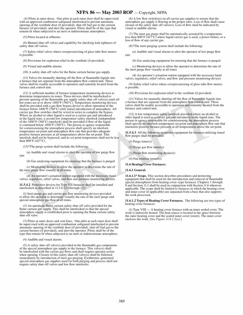
389
NFPA 86 — May 2003 ROP — Copyright, NFPA
DRAFT
(4) Pilots at outer doors. One pilot at each outer door shall be supervised with an approved combustion safeguard interlocked to prevent automatic opening of the vestibule door (if provided), shut off fuel gas to the curtain burners (if provided), and alert the operator. Pilots shall be of the type that remain lit when subjected to an inert or indeterminate atmosphere.
(5) Pilots located at effluents.
(6) Manual shut-off valves and capability for checking leak tightness of safety shut-off valves.
(7) Safety relief valves where overpressurizing of glass tube flow meters is possible.
(8) Provisions for explosion relief in the vestibule (if provided).
(9) Visual and audible alarms.
(10) A safety shut-off valve for the flame curtain burner gas supply.
(11) Valves for manually shutting off the flow of flammable liquids into a furnace that are separate from the atmosphere flow control unit. These valves shall be readily accessible to operators and remotely located from the furnace and control unit.
(12) A sufficient number of furnace temperature monitoring devices to determine temperatures in zones. These devices shall be interlocked to prevent opening of the flammable gas supply safety shut-off valve(s) until all hot zones are at or above 1400°F (760°C). Temperature monitoring devices shall be provided with a gas flow bypass device to allow operation of the furnace below 1400°F (760°C) after initial introduction of atmosphere. All carrier gas flow switches shall be wired in series to complete the bypass. Where an alcohol or other liquid is used as a carrier gas and introduced in the liquid state, a second low temperature safety interlock [independent of the 1400°F (760°C) interlock] shall be provided if flow of the liquid is continued below 1400°F (760°C). The person or agency responsible for commissioning the atmosphere process shall specify an interlock temperature set point and atmosphere flow rate that provides adequate positive furnace pressure at all temperatures above the set point. This interlock shall not be bypassed, and its set point temperature shall not be less than 800°F (427°C).
(13)*The purge system shall include the following:
(a) Audible and visual alarms to alert the operator of low purge flow rate
(b) Gas analyzing equipment for ensuring that the furnace is purged
(c) Monitoring devices to allow the operator to determine the rate of the inert purge flow visually at all times
(d) An operator’s actuation station equipped with the necessary hand valves, regulators, relief valves, and flow and pressure monitoring devices
11.5.4.2 Protective devices for Type VII furnaces shall be installed and interlocked as described in 11.5.4.2(1) through (12).
(1) Inert purge gas and carrier gas flow monitoring devices provided to allow the operator to determine visually the rate of the inert purge and special atmosphere gas flow at all times.
(2) An automatic flame curtain safety shut-off valve provided for the flame curtain gas supply. This shall be interlocked so that the special atmosphere supply is established prior to opening the flame curtain safety shut-off valve.
(3) Pilots at outer doors and vent lines. One pilot at each outer door shall be supervised with an approved combustion safeguard interlocked to prevent automatic opening of the vestibule door (if provided), shut off fuel gas to the curtain burners (if provided), and alert the operator. Pilots shall be of the type that remain lit when subjected to an inert or indeterminate atmosphere.
(4) Audible and visual alarms.
(5) A safety shut-off valve(s) provided in the flammable gas components of the special atmosphere gas supply to the furnace. This valve(s) shall be interlocked with the carrier gas flows and shall require operator action when opening. Closure of this safety shut-off valve(s) shall be followed immediately by introduction of inert gas purging. Exothermic-generated special atmosphere gas supplies used for both purging and process shall not require safety shut-off valves and low flow interlocks.
(6) A low flow switch(es) on all carrier gas supplies to ensure that the atmosphere gas supply is flowing at the proper rates. Loss of flow shall cause closure of the safety shut-off valve(s). Loss of flow shall be indicated by visual or audible alarms.
(7) The inert gas purge shall be automatically actuated by a temperature less than 800°F (427°C) where liquid carrier gas is used, a power failure, or a loss of flow of any carrier gas.
(8)*The inert purging system shall include the following:
(a) Audible and visual alarms to alert the operator of low purge flow rate
(b) Gas analyzing equipment for ensuring that the furnace is purged
(c) Monitoring devices to allow the operator to determine the rate of the inert purge flow visually at all times
(d) An operator’s actuation station equipped with the necessary hand valves, regulators, relief valves, and flow and pressure monitoring devices
(9) Safety relief valves where overpressurizing of glass tube flow meters is possible.
(10) Provisions for explosion relief in the vestibule (if provided).
(11) Valves for manually shutting off the flow of flammable liquids into a furnace that are separate from the atmosphere flow control unit. These valves shall be readily accessible to operators and remotely located from the furnace and control unit.
(12) A low temperature safety interlock provided where an alcohol or other liquid is used as a carrier gas and introduced in the liquid state. The person or agency responsible for commissioning the atmosphere process shall specify an interlock temperature set point and atmosphere flow rate that maintains positive furnace pressure at all temperatures above the set point.
11.5.4.3 All the following protective equipment for furnaces utilizing timed flow purges shall be provided:
(1) Purge timer(s)
(2) Purge gas flow meter(s)
(3) Purge flow monitoring device(s)
(4) Fan rotation sensor(s)
11.6 Heating Cover Furnaces.
11.6.1 General.
11.6.1.1* Scope. This section describes procedures and protecting equipment that shall be used for the introduction and removal of flammable special atmospheres from heating cover–type furnaces. Chapters 1 through 8 and Section 11.1 shall be used in conjunction with Section 11.6 wherever applicable. The scope shall be limited to furnaces in which the heating cover and inner cover (if applicable) are separated from a base that also supports the work processed.
11.6.1.2 Types of Heating Cover Furnaces. The following are two types of heating cover furnaces:
(1) Type VIII — A heating cover furnace with an inner sealed cover. The work is indirectly heated. The heat source is located in the space between the outer heating cover and the sealed inner cover (retort). The inner cover encloses the work. [See Figure 11.6.1.2(a).]
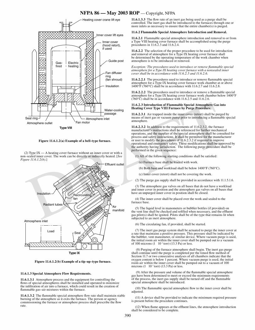
390
NFPA 86 — May 2003 ROP — Copyright, NFPA
DRAFT
���������
����������������
�������������������������
��������������������
�����������������
���������
����������
����������������������������
����������
���������������������
��������������������������������
����������������������������
Type VIII
Figure 11.6.1.2(a) Example of a bell-type furnace.
(2) Type IX — A heating cover furnace without an inner cover or with a non-sealed inner cover. The work can be directly or indirectly heated. [See Figure 11.6.1.2(b).]
Effluent outlet
Air manifold
Recirculatingfan
Insulation
Radiant tubes
Load Seal
Atmosphere inlet
Lift c
ylind
er
Type IX
Figure 11.6.1.2(b) Example of a tip-up-type furnace.
11.6.1.3 Special Atmosphere Flow Requirements.
11.6.1.3.1 Atmosphere process and the equipment for controlling the flows of special atmospheres shall be installed and operated to minimize the infiltration of air into a furnace, which could result in the creation of flammable gas–air mixtures within the furnace.
11.6.1.3.2 The flammable special atmosphere flow rate shall maintain stable burning of the atmosphere as it exits the furnace. The person or agency commissioning the furnace or atmosphere process shall prescribe the flow rate.
11.6.1.3.3 The flow rate of an inert gas being used as a purge shall be controlled. The inert gas shall be introduced to the furnaces through one or more inlets as necessary to ensure that the entire chamber(s) is purged.
11.6.2 Flammable Special Atmosphere Introduction and Removal.
11.6.2.1 Flammable special atmosphere introduction and removal to or from a Type VIII heating cover furnace shall be accomplished using the purge procedures in 11.6.2.3 and 11.6.2.4.
11.6.2.2 The selection of the proper procedure to be used for introduction and removal of atmosphere for a Type IX heating cover furnace shall be determined by the operating temperature of the work chamber when atmosphere is to be introduced or removed.
Exception: The procedures used to introduce or remove flammable special atmosphere for a Type IX heating cover furnace with a nonsealed inner cover shall be in accordance with 11.6.2.5 and 11.6.2.6.
11.6.2.2.1 The procedures used to introduce or remove flammable special atmosphere for a Type IX heating cover furnace work chamber at or above 1400°F (760°C) shall be in accordance with 11.6.2.7 and 11.6.2.8.
11.6.2.2.2 The procedures used to introduce or remove a flammable special atmosphere for a Type IX heating cover furnace work chamber below 1400°F (760°C) shall be in accordance with 11.6.2.5 and 11.6.2.6.
11.6.2.3 Introduction of Flammable Special Atmosphere Gas into Heating Cover Type VIII Furnace by Purge Procedure.
11.6.2.3.1 Air trapped inside the inner cover (retort) shall be purged by means of inert gas or vacuum pump prior to introducing a flammable special atmosphere.
11.6.2.3.2 In addition to the requirements of 11.6.2.3.2, the furnace manufacturer’s instructions shall be referenced for further mechanical operations, and the supplier of the special atmosphere shall be consulted for process and safety instructions. It shall be permitted for the manufacturer or user to modify the procedures of 11.6.2.3.2 if required to improve operational and emergency safety. These modifications shall be approved by the authority having jurisdiction. The following purge procedure shall be performed in the given sequence:
(1) All of the following starting conditions shall be satisfied:
(a) Furnace base shall be loaded with work.
(b) Both base and workload shall be below 1400°F (760°C).
(c) Inner cover (retort) shall not be covering the work.
(2) The purge gas supply shall be provided in accordance with 11.1.5.1.6.
(3) The atmosphere gas valves on all bases that do not have a workload and inner cover in position and the atmosphere gas valves on all bases that have an unpurged inner cover in position shall be closed.
(4) The inner cover shall be placed over the work and sealed to the furnace base.
(5) The liquid level in manometers or bubbler bottles (if provided) on the vent line shall be checked and refilled when necessary, and the effluent gas pilot(s) shall be ignited. Pilots shall be of the type that remains lit when subjected to an inert atmosphere.
(6) The circulating fan, if provided, shall be started.
(7) The inert gas purge system shall be actuated to purge the inner cover at a rate that maintains a positive pressure. This pressure shall be indicated by the bubbler, vent manometer, or similar device. Where vacuum purge is used, the initial room air within the inner cover shall be pumped out to a vacuum of 100 microns (1 10-1 torr) (13.3 Pa) or less.
(8) Purging of the furnace atmosphere shall begin. The inert gas purge shall continue until the purge is completed per the timed flow method of Section 11.7 or two consecutive analyses of all chambers indicate that the oxygen content is below 1 percent. Where vacuum purge is used, the initial room air within the inner cover shall be pumped out to a vacuum of 100 microns (1 10-1 torr) (13.3 Pa) or less.
(9) After the pressure and volume of the flammable special atmosphere gas have been determined to meet or exceed the minimum requirements of the process, the inert gas supply shall be turned off and the flammable special atmosphere shall be introduced.
(10) The flammable special atmosphere flow to the inner cover shall be adjusted.
(11) A device shall be provided to indicate the minimum required pressure is present before the procedure continues.
(12) When flame appears at the effluent lines, the atmosphere introduction shall be considered to be complete.
391
NFPA 86 — May 2003 ROP — Copyright, NFPA
DRAFT
(13) The base with load and inner cover then is ready for the heat-treating cycle. The outer heating cover shall be placed over the inner cover, and heat shall be applied.
11.6.2.4 Removal of Flammable Special Atmosphere Gas from Heating Cover Type VIII Furnace by Purge Procedure.
11.6.2.4.1 Combustible gases within the inner cover (retort) shall be purged before the inner cover is removed.
11.6.2.4.2 In addition to the requirements of 11.6.2.4.2, the furnace manufacturer’s instructions shall be referenced for further mechanical operations, and the supplier of the special atmosphere shall be consulted for process and safety instructions. It shall be permitted for the manufacturer or user to modify the procedures of 11.6.2.4.2 if required to improve operational and emergency safety. These modifications shall be approved by the authority having jurisdiction. The following purge procedure shall be performed in the given sequence:
(1) The purge gas supply shall be provided in accordance with 11.1.5.1.6.
(2) The outer heating cover shall be removed from over the inner cover.
(3) The flammable special atmosphere gas safety shut-off valve shall be closed, causing the inert gas to flow into the inner cover (see 11.6.4.2 ). The inert gas flow shall maintain the manufacturer’s required minimum pressure as indicated by the bubbler, vent manometer, or similar device. The inert gas purge shall continue until the purge is completed per the timed flow method of Section 11.7 or two consecutive analyses inside the inner cover indicates that the atmosphere is below 50 percent of its LEL.
(4) The pilot flame at each effluent vent line shall be shut off.
(5) The speed of the circulating fan (if required) shall be stopped or reduced.
(6) The inner cover shall be removed from over the work.
(7) The inert purge gas flow shall be shut off.
11.6.2.5 Introduction of Flammable Special Atmosphere Gas into Heating Cover Type IX Furnace by Purge Procedure.
11.6.2.5.1 Air trapped inside the heating cover, and nonsealed inner cover if applicable, shall be purged by means of inert gas or vacuum pump prior to introducing a flammable special atmosphere.
11.6.2.5.2 In addition to the requirements of 11.6.2.5.2, the furnace manufacturer’s instructions shall be referenced for further mechanical operations, and the supplier of the special atmosphere shall be consulted for process and safety instructions. It shall be permitted for the manufacturer or user to modify the procedures of 11.6.2.5.2 if required to improve operational and emergency safety. These modifications shall be approved by the authority having jurisdiction. The following purge procedure shall be performed in the given sequence:
(1) All of the following starting conditions shall be satisfied:
(a) Furnace base shall be loaded with work
(b) Both base and workload shall be below 1400°F (760°C)
(c) Heating cover shall not be covering the work
(2) The purge gas supply shall be provided in accordance with 11.1.5.1.6.
(3) The atmosphere gas valves shall be closed on all bases that do not have a workload under process.
(4) The heating cover shall be placed over the work and sealed to the furnace base.
(5) The liquid level in manometers or bubbler bottles (if provided) on the vent line shall be checked and refilled when necessary, and the effluent gas pilot(s) shall be ignited. Pilots shall be of the type that remains lit under all operating and emergency conditions.
(6) The circulating fan, if provided, shall be started.
(7) The inert gas purge system shall be actuated to purge the work chamber at a rate that maintains a positive pressure. This pressure shall be indicated by the bubbler, vent manometer, or similar device. Where vacuum purge is used, the initial room air within the inner cover shall be pumped out to a vacuum of 100 microns (1 10-1 torr) (13.3 Pa) or less.
(8) Purging of the work chamber atmosphere shall begin. The inert gas purge shall continue until the purge is completed per the timed flow method of Section 11.7 or two consecutive analyses of all chambers indicate that the oxygen content is below 1 percent. Where vacuum purge is used, the initial room air within the inner cover shall be pumped out to a vacuum of 100 microns (1 10-1 torr) (13.3 Pa) or less.
(9) After the pressure and volume of the flammable special atmosphere
gas have been determined to meet or exceed the minimum requirements of the process, the inert gas supply shall be turned off and the flammable special atmosphere gas shall be introduced.
(10) The special atmosphere flow to the work chamber shall be adjusted.
(11) A device shall be provided to indicate the minimum required pressure is present before the procedure continues.
(12) When flame appears at the effluent lines, the atmosphere introduction shall be considered to be complete.
11.6.2.6 Removal of Flammable Special Atmosphere Gas from Heating Cover Type IX Furnace by Purge Procedure.
11.6.2.6.1 Combustible gases within the heating cover, and nonsealed inner cover if applicable, shall be purged before the heating cover is opened or removed.
11.6.2.6.2 In addition to the requirements of 11.6.2.6.2, the furnace manufacturer’s instructions shall be referenced for further mechanical operations, and the supplier of the special atmosphere shall be consulted for process and safety instructions. It shall be permitted for the manufacturer or user to modify the procedures of 11.6.2.6.2 if required to improve operational and emergency safety. These modifications shall be approved by the authority having jurisdiction. The following purge procedure shall be performed in the given sequence:
(1) The purge gas supply shall be provided in accordance with 11.1.5.1.6.
(2) The flammable special atmosphere gas safety shut-off valve shall be closed, causing the inert gas to flow into the work chamber (see 11.6.4.2). The inert gas flow shall maintain the manufacturer’s required minimum pressure as indicated by the bubbler, vent manometer, or similar device. The inert gas purge shall continue until the purge is completed per the timed flow method of Section 11.7 or two consecutive analyses inside the work chamber indicates that the atmosphere is below 50 percent of its LEL.
(3) The pilot flame at effluent vent line shall be shut off.
(4) The speed of the circulating fan (if required) shall be stopped or reduced.
(5) The heating cover shall be removed from over the work.
(6) The inert purge gas flow shall be shut off.
11.6.2.7 Introduction of Flammable Special Atmosphere Gas into a Heating Cover Type IX Furnace by Burn-In Procedure.
11.6.2.7.1 The procedure in 11.6.2.7.2 shall be used only if the work chamber is at or above 1400°F (760°C).
11.6.2.7.2 In addition to the requirements of 11.6.2.7.2, the furnace manufacturer’s instructions shall be referenced for further mechanical operations, and the supplier of the special atmosphere shall be consulted for process and safety instructions. It shall be permitted for the manufacturer or user to modify the procedures of 11.6.2.7.2 if required to improve operational and emergency safety. These modifications shall be approved by the authority having jurisdiction. The following burn-in procedure shall be performed in the given sequence:
(1) All of the following starting conditions shall be satisfied:
(a) Furnace base shall be loaded with work.
(b) Both base and workload shall be below 1400°F (760°C).
(c) Heating cover shall not be covering the work.
(2) Verification of the supply of the flammable special atmosphere gas shall be made.
(3) The atmosphere gas valves shall be closed on all bases that do not have a workload under process.
(4) The heating cover shall be placed over the workload and sealed to the furnace base.
(5) The circulating fan (if provided) shall be started.
(6) The liquid level in manometers or bubbler bottles (if provided) on the vent line(s) shall be checked and refilled when necessary.
(7) The heating system shall be started and the work chamber temperature shall be raised to 1400°F (760°C) or greater.
(8) The effluent gas pilots shall be ignited at all vents where gases might be discharged from the furnace. Pilots shall be of the type that remains lit under all operating and emergency conditions.
(9) The flammable special atmosphere gas shall be introduced and the flow shall be adjusted.
392
NFPA 86 — May 2003 ROP — Copyright, NFPA
DRAFT
(10) A device shall be provided to indicate the minimum required pressure is present before the procedure continues.
(11) When flame appears at the effluent lines, the atmosphere introduction shall be considered to be complete.
11.6.2.8 Removal of Flammable Special Atmosphere Gas from a Heating Cover Type IX Furnace by Burn-Out Procedure.
11.6.2.8.1 The procedure in 11.6.2.8.2 shall be used only if the work chamber is at or above 1400°F (760°C).
11.6.2.8.2 In addition to the requirements of 11.6.2.8.2, the furnace manufacturer’s instructions shall be referenced for further mechanical operations, and the supplier of the special atmosphere shall be consulted for process and safety instructions. It shall be permitted for the manufacturer or user to modify the procedures of 11.6.2.8.2 if required to improve operational and emergency safety. These modifications shall be approved by the authority having jurisdiction. The following burn-out procedure shall be completed in the given sequence before the work chamber temperature falls below 1400°F (760°C):
(1) Where required, pilots or torches shall be ignited and placed in position or shall be ready for ignition of the flammable atmosphere gas at the heating cover to the base seal as soon as the seal is broken.
(2) The heat source shall be turned off.
(3) The speed of the circulating fan (if provided) shall be stopped or reduced.
(4) Any mechanical clamping devices (if used) that hold the heating cover to the base shall be released.
(5)* The heating cover shall be separated gradually from the base. The flammable atmosphere gas shall ignite or shall be ignited as soon as the heating cover breaks its seal with the base.
(6) The flammable special atmosphere gas inlet valve shall be closed.
11.6.3 Emergency Shutdown for Heating Cover–Type Furnaces.
11.6.3.1 In the event of electric power failure or loss of flammable special atmosphere flow, all the following actions shall be initiated:
(1) An inert gas safety purge system, as prescribed in 11.6.4.1(5), shall be actuated immediately.
(2) The flammable atmosphere safety shut-off valve shall be closed.
(3) All manual flammable atmosphere gas valves shall be closed.
(4) The inert gas safety purge shall be continued as long as necessary to purge the flammable gas from the work chamber.
(5) The flow of the inert gas safety purge shall be actuated at a rate that maintains a positive pressure in the work chamber for the duration of the purge.
(6) The inert gas purge shall continue until the purge is completed per the timed flow method of Section 11.7 or two consecutive analyses inside the work chamber indicates that the atmosphere is below 50 percent of its LEL.
11.6.3.2* In the event of a disruption in atmosphere circulation, atmosphere flow into the furnace shall be continued on an emergency basis to maintain positive pressure until fan operation is restored or until the heating cover is removed from the base and all remaining flammable atmosphere can be removed by other means, such as by burning out and thereby retarding air infiltration. Neither timed flow purging methods nor analyses of purge vent gas shall be used to determine when purging can be stopped.
11.6.4 Protective Equipment for Heating Cover–Type Furnaces above 1400°F (760°C).
11.6.4.1 The following protective equipment and procedures shall be required in conjunction with the special atmosphere gas system:
(1) A safety shut-off valve on the flammable special atmosphere gas supply line to the furnace.
(2) An atmosphere gas flow indicator(s) to allow the operator to determine the rate of atmosphere gas flow visually at all times.
(3) Furnace temperature monitoring devices to determine the temperature in all zones. These devices shall be interlocked to prevent opening of the atmosphere gas safety shut-off valve until all zones are at or above 1400°F (760°C) where inert gas or vacuum purging of oxygen from the initial room air within the work chamber is not employed.
(4) Audible and visual alarms to alert the furnace operator of abnormal furnace temperature or low atmosphere flow conditions detected by the monitoring devices as recommended, giving the operator the opportunity to perform any required shutdown procedure safely.
(5) The purge gas supply shall be provided in accordance with 11.1.5.1.6.
(6) Valves for manually shutting off the flow of flammable special atmosphere to the furnace. These valves shall be readily accessible to the operator and remotely located from the furnace.
(7) Pilots at all effluent vent lines. These pilots shall be monitored to alert the operator of pilot failure.
11.6.4.2 The inert purge system(s) shall include all of the following:
(1) Audible and visual alarms to alert the operator of low purge flow rate
(2) Gas analyzing equipment for ensuring that the furnace is purged
(3) Monitoring devices to allow the operator to determine the rate of the inert purge flow visually at all times
(4) A provision to allow the operator to start the inert purge manually whenever desired.
11.6.4.3 The inert purge piping system shall be arranged so that whenever the control valve in the inert gas line is open, the flammable special atmosphere gas line is closed.
11.6.4.4 All piping and wiring connections to removable heating covers shall be painted, keyed, or otherwise marked to minimize the
11.6.4.5 Automatic pressure makeup of the work chamber shall be provided on furnace equipment where operator monitoring of indicators such as pressure and flow rates cannot be ensured.
11.6.4.6 All the following protective equipment for furnaces utilizing timed flow purges shall be provided:
(1) Purge timer(s)
(2) Purge gas flow meter(s)
(3) Purge flow monitoring device(s)
(4) Fan rotation sensor(s)
11.6.5* Operating Precautions for Heating Cover–Type Furnaces. The rate of separating a heating cover from or rejoining a heating cover to the inner cover shall not exceed a rate that causes rapid expansion or contraction of the atmosphere gas inside the inner cover.
11.7* Timed Flow Purge Method for Type I–IX Furnaces.
11.7.1* Purging after Failure of Atmospheric Circulation. When the timed purge has been established with circulating fans operating, a purge time extension shall be applied if the fans are inoperative.
CAUTION: Purging without atmosphere circulation can leave pockets of combustible gases inside a furnace.
11.7.2 Timed Flow Purging Trials.
11.7.2.1 At the time of commissioning or initial start-up, the equipment supplier, or the agency authorizing purchase of the furnace, shall perform trials that confirm the adequacy and effectiveness of a timed flow purge. The test data and results shall be recorded and maintained as a permanent record and made available to the authority having jurisdiction.
11.7.2.2 The trial shall be conducted using ambient temperature purge gas flowed into an unheated furnace. The work chamber shall not contain work or any objects that reduce its internal volume. Atmosphere circulation fans inside the furnace shall have proven operation during the entire purge period.
11.7.2.3 The trials shall incorporate all of the following:
(1) Verification that the purge gas flow rate or cumulative volume measurement is correct.
(2) Verification that the measured purge gas flow rate or volume is undiminished at the furnace atmosphere outlet or inlet to each individual furnace. In the latter case, there shall be no further downstream branching, tees, valves, or openings in the pipeline — only the inlet to the furnace.
(3) Use of a gas analyzing instrument(s) that is listed and calibrated in accordance with the manufacturer’s instructions.
11.7.2.4 Where oxygen is being purged out of a furnace using an inert gas, verification testing shall be considered acceptable if, after five furnace volume changes of flow, two consecutive gas analyses of the effluent gas indicate less than 1 percent oxygen by volume.
11.7.2.5 Where a combustible atmosphere is being purged out of a furnace using an inert gas, verification testing shall be conducted at the typical purging temperature and considered acceptable if, after five furnace volume changes of flow, two consecutive gas analyses of the effluent gas indicate less than 50 percent of the LEL.
393
NFPA 86 — May 2003 ROP — Copyright, NFPA
DRAFT
11.7.3* Future Purge Verifications. Trials prescribed in 11.7.2 shall be repeated periodically, as specified in the furnace manufacturer’s instructions, to verify that future alterations to the furnace or atmosphere piping have not diminished the effectiveness of the purge. The user shall perform the retests and retain written records of the results for review by the authority having jurisdiction.
11.7.4 Failure to Verify Timed Flow Purge Effectiveness. In the event that the trials in 11.7.2 and 11.7.3 fail to verify the effectiveness of the purge process, procedures utilizing gas analyzers to prove completeness of purges shall be utilized until the cause of the failure is found and remedied and successful trials are completed.
11.8 Integral Quench Furnaces.
11.8.1* Scope. Section 11.8 shall provide procedures and protective equipment of Class C furnaces to which is added an enclosed quench tank. Section 11.9 shall address protection of open liquid quench tanks. Section 11.10 shall address protection of molten salt bath equipment. This section shall not cover procedures and protective equipment of central quench medium cooling systems.
11.8.2 Quench Vestibule.
11.8.2.1 The quench vestibule shall be constructed of noncombustible materials consistent with the fire and explosion hazards inherent to such equipment.
11.8.2.2 The inner door between the furnace and quench shall seal the opening in order to serve as an insulated baffle to block heat loss to the quench vestibule.
11.8.2.3 Emergency or service access shall be provided.
11.8.2.4 All outer load and unload doors shall be equipped with pilots that are stable under all operating conditions.
11.8.2.5 The quench vestibule shall be supplied with an atmosphere gas supply to maintain safe conditions during the entire process cycle. The introduction and maintenance of this atmosphere shall be in accordance with Sections 11.3 and 11.5.
11.8.2.6 An effluent line (flammable atmosphere vent) shall be provided to control the pressure equilibrium in the chamber. The vent opening shall be located so that operators are not exposed to injury upon pressure release.
11.8.2.7 A stable pilot shall be provided at the effluent line and will be sized to ignite the vented gases under all operating conditions.
11.8.2.8 Manual facilities shall be provided to allow opening of the outer quench vestibule door. Opening of this door under emergency conditions shall be the decision of operating personnel.
11.8.3 Cooling Chamber Design.
11.8.3.1 Base materials, weld filler materials, and welding procedures used for the cooling chamber shall be selected to provide resistance to corrosion by the cooling medium.
11.8.3.2 Where the quench medium temperature is excessive for desired jacket cooling, a separate heat exchanger shall be employed.
11.8.3.3 Where a water-cooled heat exchanger is used, the quench oil circulating pump shall be installed on the inlet side of the heat exchanger and the quench medium pressure always shall exceed that of the cooling water. A differential pressure switch shall be required and interlocked with the quench cycle.
11.8.3.4 Where steel plate coils are attached by thermal contact cement to the external surfaces of the quench chamber, fabricated of hot-rolled steel plate, the junction shall not cause the possibility of a water leak into the quench reservoir.
11.8.3.5 Where serpentine coils formed from a noncorrosive tubing material are brazed or welded to the exterior surfaces of a cooling chamber fabricated of hot-rolled steel plate, the junction shall not cause the possibility of a water leak into the quench tank.
11.8.3.6 Automatic temperature controls shall be installed in pressure-type water-cooling and oil-cooling systems to ensure the desired jacket temperature.
11.8.4* Elevator Design.
11.8.4.1 The elevating mechanism shall be supported substantially by structural members in order to handle the maximum rated loads.
11.8.4.2 Elevator guides or ways shall be provided to ensure uniform stabilized movement of the elevator in the confined areas of the quench tank.
11.8.4.3 Tray guides or stops shall be provided to ensure the tray is positioned in the correct orientation on the elevator.
11.8.4.4 Outer door operation shall be interlocked in the automatic mode so that it cannot open unless the elevator is in its full up or down position or upon extinguishment of the flame-supervised outer door pilot, except through action of manual override in emergencies. (See 11.8.2.8.)
11.8.5 Lower Quench Chamber or Tank.
11.8.5.1 The quench tank shall be designed and constructed to do the following:
(1) Contain the quench medium capacity at the expected operating temperature and with maximum workload volume
(2) Operate with a maximum quench medium level, where the elevator and work load are submerged, of not less than 6 in. (152 mm) below the door or any opening into the furnace
11.8.5.2 The quench tank shall be tested for leaks prior to initial use. Any leaks identified shall be repaired before putting the tank into service.
11.8.5.3 The quench tank shall have the capacity to quench a maximum gross load with a maximum temperature rise that cannot exceed 50°F (28°C) below the flash point and shall have cooling capabilities to return the quench medium to a satisfactory temperature range between minimum quench cycles.
11.8.5.4 The quench tank shall be provided with an overflow, sized for the expected overflow volume, which is directed to a location outside of the building or to a salvage tank. Overflow shall be trapped or otherwise arranged to prevent the loss of quench chamber atmosphere gas and to prevent a siphon effect.
11.8.6 Overflow Drains.
11.8.6.1* Quench tanks of over 150 gal (568 L) in liquid capacity or 10 ft2 (0.9 m2) in liquid surface area shall be equipped with a trapped overflow pipe leading to a location where the overflow volume will not create a hazard.
11.8.6.1.1 Overflow pipes shall be sized to handle the maximum delivery of quench tank liquid fill pipes, but shall not be less than 3 in. (76 mm) in diameter, and shall be increased in size, depending upon the area of the liquid surface and the length and pitch of pipe.
11.8.6.1.2* If the liquid surface area of a quench tank is 75 ft2 to 150 ft2 (7 m2 to 14 m2), the diameter of the overflow pipe shall be not less than 4 in. (102 mm); if 150 ft2 to 225 ft2 (14 m2 to 21 m2), not less than 5 in. (127 mm); if 225 ft2 to 325 ft2(21 m2 to 30 m2), not less than 6 in. (152 mm).
11.8.6.2 Overflow pipes shall be connected to quench tanks through an outlet where the accumulation of caked or dried material cannot clog the overflow opening.
11.8.6.3 Piping connections on drains and overflow lines shall be designed to allow ready access for inspection and cleaning.
11.8.6.3.1* The bottom of the overflow connection shall be not less than 6 in. (152 mm) below the top of the tank for open integral quench tanks.
11.8.6.3.2* The bottom of the overflow connection shall be not less than 6 in. (152 mm) below the lowest operating oil level for closed integral quench tanks.
11.8.7* Quench Medium Cooling Systems.
11.8.7.1 Heat Exchanger within Quench Tank.
11.8.7.1.1 The heat exchanger shall be constructed of materials that cannot be corroded by either cooling medium or quench medium.
11.8.7.1.2 The heat exchanger shall be subjected to a minimum pressure test of 150 percent of the maximum designed working pressure after installation in the quench tank.
11.8.7.1.3 The heat exchanger shall be located within the quench tank in a manner that prevents mechanical damage by the elevator or by the load to be quenched.
11.8.7.1.4 The cooling medium flow shall be controlled by an automatic temperature control.
11.8.7.1.5 A pressure-relief device shall be provided to protect the heat exchanger. Relief shall be piped to a location that will not create a hazard.
11.8.7.1.6 Water shall not be used as a cooling medium within a quench tank utilizing a combustible liquid quench medium.
11.8.7.2 External Liquid-Cooled Heat Exchanger.
11.8.7.2.1 Heat exchanger tubes that are exposed to water shall be constructed of corrosion-resistant materials.
394
NFPA 86 — May 2003 ROP — Copyright, NFPA
DRAFT
11.8.7.2.2 After fabrication, the heat exchanger shall be subjected to a minimum pressure test of 150 percent of the maximum designed working pressure.
11.8.7.2.3 The pressure of the quench medium through the heat exchanger shall be greater than the coolant pressure applied. A differential pressure switch shall be required and interlocked with the quench cycle.
11.8.7.2.4 A pressure-relief device shall be provided to protect the heat exchanger. Relief shall be piped to a location that will not create a hazard.
11.8.7.3 External Air-Cooled Heat Exchanger.
11.8.7.3.1 External air-cooled heat exchangers installed outdoors shall be reinforced structurally to withstand anticipated wind forces without damage at the elevation at which they are mounted.
11.8.7.3.2 External air-cooled heat exchangers that are installed outdoors or that utilize supplemental water-cooling shall be constructed of materials that are able to withstand corrosion.
11.8.7.3.3 An external heat exchanger installed outdoors shall be provided with lightning protection if located in an exposed, rooftop location.
11.8.7.3.4 If the air-cooled heat exchanger is installed in a rooftop location, it shall be installed in a curbed or diked area and drained to a location outside of the building where it will not create a hazard.
11.8.8* Quench Tank Protective Features.
11.8.8.1 The quench reservoir shall be equipped with a quench medium level indicator.
11.8.8.2 If of the sight-glass type, the level indicator shall be of heavy-duty construction and protected from mechanical damage.
11.8.8.3 The quench tank shall be equipped with a low-level device arranged to sound an alarm, to prevent the start of quenching, and to shut off the heating medium in case of a low-level condition.
11.8.8.4 The quench tank shall be equipped with an excess temperature limit control device arranged to do the following:
(1) Sound an alarm
(2) Automatically shut off the quench heating medium
(3) Prevent the start of a quench
11.8.8.5 Where agitation of the quench medium is required to prevent overheating, the agitation shall be interlocked to prevent quenching until the agitator has been started.
11.8.8.6 The quench oil shall be analyzed for water contamination.
11.8.8.6.1* Laboratory testing shall be permitted to be used to determine the existence of water in quench oil.
11.8.8.6.2* A representative sample of quench oil shall be obtained.
11.8.8.6.3* Quench oil shall be tested for water content whenever there is a possibility that water has contaminated the quench oil system.
11.8.8.6.4 Quenching operations shall be prohibited until the water contamination is corrected and confirmed by test.
11.8.9 Quench Tank Heating Controls.
11.8.9.1 Fuel-Fired Immersion Heaters.
11.8.9.1.1 Fuel-fired immersion heaters shall be installed in accordance with Chapters 5, 6, and 7.
11.8.9.1.2 Burner control systems shall be interlocked with the quench medium agitation system or the recirculating system, or both, to prevent localized overheating of the quench medium.
11.8.9.1.3 The immersion tubes shall be installed so that the entire tube within the quench tank is covered with quench medium at all times.
11.8.9.1.4 A quench medium level control and excess temperature supervision shall be interlocked to shut off fuel-fired immersion heating when low quench level or overtemperature is detected.
11.8.9.2 Electric Immersion Heaters.
11.8.9.2.1 Electric immersion heaters shall be of sheath-type construction.
11.8.9.2.2 Heaters shall be installed so that the hot sheath is fully submerged in the quench medium at all times.
11.8.9.2.3 The quench medium shall be supervised by both of the following:
(1) A temperature controller that maintains the quench medium at the proper temperature
(2) A quench medium level control and excess temperature supervision that are interlocked to shut off the electric immersion heating when low quench level or overtemperature is detected.
11.8.9.2.4 The electrical heating system shall be interlocked with the quench medium agitation system to prevent localized overheating of the quench medium.
11.9* Open Liquid Quench Tanks.
11.9.1* Scope. This section shall apply to the open tank quenching of heated metals in combustible quench media. It shall not apply to salt quench tanks or central quench medium cooling systems.
11.9.2 Location. Tanks shall be located as far as practicable from furnaces and shall not be located on or near combustible floors. Combustible materials shall not be stored in the vicinity of the quench tank.
11.9.3 Quench Tank Construction.
11.9.3.1 Construction. The tank shall be constructed of noncombustible material and shall be supported securely and rigidly. Supports for tanks over 500 gal (1893 L) in capacity or 10 ft2 (1 m2) in liquid surface area shall have a minimum fire resistance rating of 1 hour.
11.9.3.2 Location. The top of the tank shall be at least 6 in. (152 mm) above the floor.
11.9.3.3 Tank Features. Floating the flaming liquid out of the tank due to the collection of the automatic sprinkler discharge in the tank in the event of a fire shall be prevented by one or more of the following:
(1) Oil drain boards shall be arranged so sprinkler discharge cannot be conducted into the tank.
(2) Tanks shall be equipped with automatically closing covers.
(3) Tanks shall be equipped with overflow pipes. (See 11.9.3.5.)
11.9.3.4 Liquid Level. The level of liquid in the tanks shall be maintained at 6 in. (152 mm) or greater below the top of the tank to allow effective application of extinguishing agents in the event of fire.
11.9.3.5* Overflow Pipes.
11.9.3.5.1 Tanks of over 150 gal (570 L) in capacity, or 10 ft2 (1 m2) in liquid surface area, shall be equipped with a trapped overflow pipe leading to a location where the overflow will not create a hazard.
11.9.3.5.2 Depending upon the area of the liquid surface and the length and pitch of the pipe, overflow pipes for quench tanks over 150 gal (570 L) in capacity, or 10 ft2 (1 m2) in area, shall be capable of handling the maximum delivery of quench tank liquid fill pipes, or automatic sprinkler discharge, but shall not be less than 3 in. (76 mm) in diameter.
11.9.3.5.3 Piping connections on drains and overflow lines shall be designed for ready access for inspection and cleaning of the interior.
11.9.3.5.4 Overflow pipes installed in quench tanks shall have a minimum liquid entry level of 6 in. (152 mm) below the top of the tank.
11.9.3.5.5 Overflow pipes shall not contain any valves or other restrictions.
11.9.3.6 Emergency Drains.
11.9.3.6.1 The provisions of this section shall not apply to integral quench furnaces.
11.9.3.6.2 Tanks over 500 gal (1900 L) in liquid capacity shall be equipped with bottom drains arranged to drain the tank quickly, both manually and automatically, in the event of fire.
Exception: Bottom drains shall not be necessary if the viscosity of the liquid at ambient temperatures makes their use impractical.
11.9.3.6.3 Drain facilities from the bottom of a tank shall be permitted to be combined with the oil-circulating system or arranged independently to drain the oil to a location where the oil will not create a hazard.
11.9.3.6.3.1 Emergency drains shall use gravity flow or automatic pumps.
11.9.3.6.3.2 Such drain facilities shall be trapped and shall discharge to a closed, vented salvage tank or to a location outside where the oil will not create a hazard.
11.9.3.6.4 Manual operation shall be from an accessible location.
11.9.4 Equipment.
395
NFPA 86 — May 2003 ROP — Copyright, NFPA
DRAFT
11.9.4.1 Transfer. Controls of transfer equipment shall be installed in a location so that the operator can be protected in the event of oil flash while the work is being lowered.
11.9.4.2 Temperature Control of Liquids.
11.9.4.2.1 To prevent overheating the oil, the tank and cooling system shall be designed with the capacity to keep the oil temperature at least 50°F (28°C) below its flash point under maximum work load conditions.
11.9.4.2.2 The cooling system shall be constructed with an external heat exchanger and shall be controlled so that any leakage is from the oil to the water. Water-cooling coils shall not be installed within the quench tank. Loss of the controlled condition shall be alarmed.
11.9.4.2.3 On open tanks with heating systems, automatic temperature control shall be provided to maintain the oil at the desired working temperature. This temperature shall be more than 50°F (28°C) below the flash point of the oil. Controls shall be interlocked to prevent starting the heating system, unless the tank agitator or recirculation pump is in operation.
11.9.4.2.4 An excess temperature limit switch that is independent of operating temperature controls shall be provided on all quench tanks where any of the following conditions exist:
(1) The liquid surface area exceeds 10 ft2 (1 m2).
(2) Incoming or outgoing work is handled by conveyor.
(3) Artificial cooling is required to maintain the oil temperature at least 50°F (28°C) below the flash point.
(4) The tank is equipped with a heating system.
11.9.4.2.5* The excess temperature limit switch shall be set at least 50°F (28°C) below the flash point of the oil. On operation, the excess temperature limit switch shall actuate an audible and visual alarm, shut down any quench oil heating system, and, if not in operation, start up oil recirculation or agitation and the tank cooling system. Where sudden stoppage cannot result in partial submergence of work, the excess temperature limit switch also shall shut down the conveyor.
11.9.4.3 Low Oil Level Sensor. A low oil level sensor shall be provided to sound an alarm in the event that the oil level is below the prescribed limits where any of the following conditions exist:
(1) The liquid surface area exceeds 10 ft2 (1 m2).
(2) Incoming or outgoing work is handled by a conveyor.
(3) The tank is equipped with a heating system.
11.9.4.4 Hoods. Tanks shall be provided with a noncombustible hood and vent or other equally effective means to facilitate removal of vapors from the process and to prevent condensate from forming on roof structures. All such vent ducts shall be treated as flues and shall be kept well-separated from combustible roofs or materials. Hoods and ducts shall be protected with an approved automatic extinguishing system and shall be located so as not to interfere with fire protection facilities for the quench tank.
11.9.5* Protection.
11.10 Molten Salt Bath Equipment.
11.10.1* General.
11.10.1.1 Scope. Section 11.10 shall cover molten salt bath furnaces, internal salt quench tanks, and associated equipment. Molten salt bath furnaces shall include any heated container that holds a melt or fusion of one or more relatively stable salts used as a fluid medium into which metalwork is immersed.
11.10.1.2 Responsibility. Molten salt bath equipment shall be designed, constructed, and operated for a specific process.
11.10.1.2.1 Responsibility for selection shall be that of the person or agency authorizing the purchase of the equipment and that of the manufacturer supplying the equipment.
11.10.1.2.2 Responsibility for observing the operating instructions shall be that of the person or agency operating the equipment.
11.10.2 Location and Construction.
11.10.2.1 Location.
11.10.2.1.1 An area, consistent with the hazards of salt bath furnaces, shall be allocated for the installation of all salt bath equipment, and the zone of operation immediately around the bath shall be kept clear to prevent congestion and to prevent interference with process operations.
11.10.2.1.2 Salt bath equipment shall be located either inside a shallow, cement-lined pit or within a curbed area. In either case, the pit or curbed area
shall be designed to contain the contents of the molten salt in the furnace. Equipment with outer walls constructed and maintained in a manner to be salt-tight to prevent leakage if the inner wall fails shall not require curbing.
11.10.2.1.3 Salt bath equipment shall be located so that the bath is not exposed to leakage from overhead liquid-conveying piping (e.g., service piping, steam piping, sprinkler piping, oil piping), liquid entry through wall openings (e.g., windows, air intakes), or anticipated leakage or seepage through the roofs or floors above. Where it is not possible to protect against possible liquid leakage entering the salt bath because of location, the salt bath shall be provided with a noncombustible hood that is designed and installed so that leakage into the molten salt is impossible.
11.10.2.1.4 Where adjacent equipment (e.g., oil or water quench tanks) are located so that potential splashover could expose a molten salt bath, the adjacent equipment shall be provided with deflecting baffles or guards to prevent the splashover from entering the salt bath.
11.10.2.2 Construction.
11.10.2.2.1 Molten salt bath equipment shall be constructed of noncombustible materials.
11.10.2.2.2 Molten salt bath equipment shall be constructed of materials that are resistant to the corrosive action of chemical salts at the maximum design operating temperature.
11.10.2.2.3 The design of molten salt baths, and the materials selected for their construction, shall minimize the possible effects of explosions, fires, spattering, and leakage, with regard for the protection of property and the safety of operating personnel.
11.10.2.2.4 The requirements of Chapter 5 also shall apply for the construction of salt bath equipment except as specified in 11.10.2.1.2.
11.10.3 Salts.
11.10.3.1 General. For the purpose of this section, a salt shall be considered to be any chemical compound, or mixture of compounds, that is utilized to form a melt or fluid medium into which metal parts are immersed for processing.
11.10.3.2 Storage and Handling.
11.10.3.2.1* All salts shall be stored in tightly covered containers that are designed to prevent the possible entrance of liquids or moisture.
11.10.3.2.2 All storage and shipping containers shall be marked prominently with the identification of the salt (or salt mixture) they contain to minimize the possibility of accidentally mixing noncompatible salts.
11.10.3.2.3 The supply of nitrate salts shall be stored in a separated, fireproof, and moisture-free room or area located away from heat, liquids, and reactive chemicals. This room or area shall be secured against entry by unauthorized personnel at all times. Only the amount of nitrate salt needed shall be removed from the storage room or area that is required for makeup or full-bath charges. Where nitrate salts have been transported to the equipment area, they shall be added to the salt bath immediately. Excess salt shall not be permitted in the equipment area.
11.10.3.2.4 The salt bath area shall be kept clear of paper sacks or bags to avoid fires.
11.10.3.2.5 All restrictions applying to nitrate/nitrite salts also shall apply to cyanide salts. Operating procedures shall be implemented to ensure that mixing of cyanide and nitrate/nitrite salts cannot occur.
CAUTION: Mixing of cyanide and nitrate/nitrite salts can cause an explosion.
11.10.4 Heating Systems.
11.10.4.1 General.
11.10.4.1.1 For the purpose of 11.10.4, the term salt bath heating system shall include the heating source and all associated piping, electrodes, radiant tubes, and all other equipment or devices used to convey the heat safely to the bath that are necessary to create the salt melt or fusion.
11.10.4.1.2 The requirements of Chapters 6 and 7 shall apply.
11.10.4.2 Gas and Oil Heating Systems.
11.10.4.2.1 The design of salt bath equipment shall not permit direct flame impingement upon the wall of the salt container.
11.10.4.2.2 Where burner immersion tubes or radiant tubes are used, the design shall prevent any products of combustion from entering the salt bath.
11.10.4.2.3 All immersion or radiant tubes shall be fabricated of materials that are resistant to the corrosive action of the salt, or salt mixture, being used.
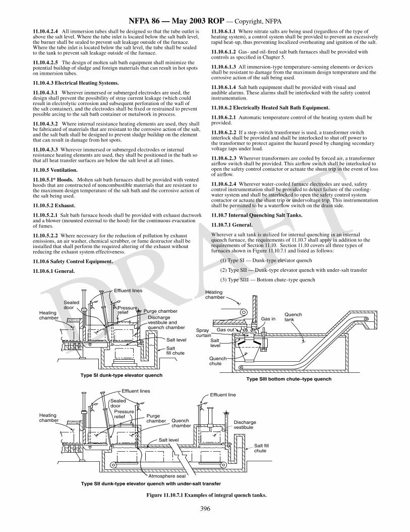
396
NFPA 86 — May 2003 ROP — Copyright, NFPA
DRAFT
11.10.4.2.4 All immersion tubes shall be designed so that the tube outlet is above the salt level. Where the tube inlet is located below the salt bath level, the burner shall be sealed to prevent salt leakage outside of the furnace. Where the tube inlet is located below the salt level, the tube shall be sealed to the tank to prevent salt leakage outside of the furnace.
11.10.4.2.5 The design of molten salt bath equipment shall minimize the potential buildup of sludge and foreign materials that can result in hot spots on immersion tubes.
11.10.4.3 Electrical Heating Systems.
11.10.4.3.1 Wherever immersed or submerged electrodes are used, the design shall prevent the possibility of stray current leakage (which could result in electrolytic corrosion and subsequent perforation of the wall of the salt container), and the electrodes shall be fixed or restrained to prevent possible arcing to the salt bath container or metalwork in process.
11.10.4.3.2 Where internal resistance heating elements are used, they shall be fabricated of materials that are resistant to the corrosive action of the salt, and the salt bath shall be designed to prevent sludge buildup on the element that can result in damage from hot spots.
11.10.4.3.3 Wherever immersed or submerged electrodes or internal resistance heating elements are used, they shall be positioned in the bath so that all heat transfer surfaces are below the salt level at all times.
11.10.5 Ventilation.
11.10.5.1* Hoods. Molten salt bath furnaces shall be provided with vented hoods that are constructed of noncombustible materials that are resistant to the maximum design temperature of the salt bath and the corrosive action of the salt being used.
11.10.5.2 Exhaust.
11.10.5.2.1 Salt bath furnace hoods shall be provided with exhaust ductwork and a blower (mounted external to the hood) for the continuous evacuation of fumes.
11.10.5.2.2 Where necessary for the reduction of pollution by exhaust emissions, an air washer, chemical scrubber, or fume destructor shall be installed that shall perform the required altering of the exhaust without reducing the exhaust system effectiveness.
11.10.6 Safety Control Equipment.
11.10.6.1 General.
11.10.6.1.1 Where nitrate salts are being used (regardless of the type of heating system), a control system shall be provided to prevent an excessively rapid heat-up, thus preventing localized overheating and ignition of the salt.
11.10.6.1.2 Gas- and oil-fired salt bath furnaces shall be provided with controls as specified in Chapter 5.
11.10.6.1.3 All immersion-type temperature-sensing elements or devices shall be resistant to damage from the maximum design temperature and the corrosive action of the salt being used.
11.10.6.1.4 Salt bath equipment shall be provided with visual and audible alarms. These alarms shall be interlocked with the safety control instrumentation.
11.10.6.2 Electrically Heated Salt Bath Equipment.
11.10.6.2.1 Automatic temperature control of the heating system shall be provided.
11.10.6.2.2 If a step-switch transformer is used, a transformer switch interlock shall be provided and shall be interlocked to shut off power to the transformer to protect against the hazard posed by changing secondary voltage taps under load.
11.10.6.2.3 Wherever transformers are cooled by forced air, a transformer airflow switch shall be provided. This airflow switch shall be interlocked to open the safety control contactor or actuate the shunt trip in the event of loss of airflow.
11.10.6.2.4 Wherever water-cooled furnace electrodes are used, safety control instrumentation shall be provided to detect failure of the cooling-water system and shall be interlocked to open the safety control system contactor or actuate the shunt trip or undervoltage trip. This instrumentation shall be permitted to be a waterflow switch on the drain side.
11.10.7 Internal Quenching Salt Tanks.
11.10.7.1 General.
Wherever a salt tank is utilized for internal quenching in an internal quench furnace, the requirements of 11.10.7 shall apply in addition to the requirements of Section 11.10. Section 11.10 covers all three types of furnaces shown in Figure 11.10.7.1 and listed as follows:
(1) Type SI — Dunk-type elevator quench
(2) Type SII — Dunk-type elevator quench with under-salt transfer
(3) Type SIII — Bottom chute-type quench
���������������
��������������
�������������
����������
Type SII dunk-type elevator quench with under-salt transfer
�������������������
���������������
���������������
�����������
���������������
��������������
�������������
���������������
�����������
��������������
��������������� �������������
��������������������������������������
����������
���������������
���������������������������������
���������������
�����������������
��������������������
����������
������������
����������������������������������
Figure 11.10.7.1 Examples of integral quench tanks.
397
NFPA 86 — May 2003 ROP — Copyright, NFPA
DRAFT
11.10.7.2 Safety Control Equipment — Type SI and Type SII.
11.10.7.2.1* The composition of the atmosphere in the furnace shall be controlled and monitored to prevent free carbon or soot originating in the furnace atmosphere from being transferred into the quench tank.
11.10.7.2.2 Circulation shall be provided to ensure that the maximum temperature of the salt in contact with the hot work is below the decomposition temperature of the salt as specified by the salt manufacturer by a minimum of 200°F (111°C).
11.10.7.2.3 A means shall be provided to ensure that salt cannot enter the heating chamber by capillary action on the side wall of the chute or tank.
11.10.7.2.4 Condensation and freezing of the salt at the atmosphere interface shall be prevented by the following:
(1) Insulating or heating the salt fill to maintain a temperature above the freezing point of the salt (see Figure 11.10.7.1)
(2) Insulating the vestibule to maintain the temperature above the freezing point of the salt (see Figure 11.10.7.1)
11.10.7.2.5 The design shall be such that horizontal shelves or ledges are minimized to prevent carbon, salt, or particulates from accumulating.
11.10.7.2.6 Each transfer chamber and discharge vestibule shall be provided with a separate atmosphere vent(s). The vent(s) shall be located so that the operators are not exposed to injury when pressure relief takes place. A pilot shall be provided at the vent outlets to ignite vented gases.
11.10.7.2.7 In addition to the vent(s) required in 11.10.7.2.6, a pressure-relief device shall be provided for the quench chamber in order to do both of the following:
(1) Keep the internal pressure from exceeding the design limits of the equipment
(2) Prevent salt overflow from the fill chute
11.10.7.2.8 The fill chute shall have freeboard to prevent salt overflow at peak vestibule pressure.
11.10.7.3 Safety Control Equipment — Type SIII.
11.10.7.3.1* The composition of the atmosphere in the furnace shall be controlled and monitored to prevent free carbon or soot originating in the furnace atmosphere from being transferred into the quench tank.
11.10.7.3.2 Circulation shall be provided to ensure that the maximum temperature of the salt in contact with the hot work is below the decomposition temperature of the salt as specified by the salt manufacturer by a minimum of 200°F (111°C).
11.10.7.3.3 Circulation of the liquid in the chute shall be provided to ensure that the salt does not become stagnant at the liquid surface.
11.10.7.3.4 A means shall be provided to ensure that salt cannot enter the heating chamber by capillary action on the side wall of the chute or tank.
11.10.7.3.5 Condensation and freezing of the salt at the liquid surface shall be prevented by heating or insulating the quench chute and salt fill to maintain a temperature above the freezing point of the salt.
11.10.7.3.6 The design shall be such that horizontal shelves or ledges are minimized to prevent carbon, salts, or particulates from accumulating.
11.10.7.4 High Temperature Salt Bath Quench Tanks. Salt bath quench tanks that operate between 700°F and 1300°F (371°C and 704°C) shall utilize salts, or salt mixtures, that are chemically and physically stable at the operating temperatures and are nonreactive to the furnace atmospheres.
11.10.7.5 Low Temperature Salt Quench Tanks. Salt quench tanks operating at 350°F to 750°F (177°C to 399°C), and utilizing a combination of sodium or potassium nitrites and nitrates in conjunction with a combustible atmosphere above all or part of the salt quench surface, shall be designed to provide adequate circulation of salt in the area in which hot parts enter to prevent temperature rise on the surface of the salt.
11.10.8 Cooling. Internal water-cooled coils and jackets shall not be used. The salt bath shall be cooled by natural means (i.e., direct radiation and conduction to the ambient surroundings). If these means are insufficient to maintain operating temperatures, then forced cooling shall be promoted by several proven means, using air as the cooling medium.
11.10.9* Operator Precautions.
11.10.9.1 Each molten salt bath operator shall be trained, as specified in Section 4.2. Only trained, qualified operators shall be permitted to operate or service molten salt bath furnaces.
11.10.9.2 Each molten salt bath installation shall be furnished with a prominently displayed wall chart, which shall be supplied by the salt
manufacturer. This wall chart shall state which salt or salt mixtures shall be used and shall identify the maximum design operating temperature.
11.10.9.3 A complete operation and service manual shall be available at each salt bath furnace, and the operator shall have access to the operation manual at all times.
11.10.10 Precautions.
11.10.10.1 All items such as fixtures, tools, baskets, and parts that are to be immersed in a molten salt bath shall be made of solid bar materials and shall be completely dry.
11.10.10.2* No attempt shall be made to break freezing crust manually while the furnace is in operation. Instead, the temperature of the bath shall be raised gradually until the crust melts. The bath temperature shall not exceed the maximum design operating temperature at any time.
11.10.10.3 All salt bath covers shall be in the closed position whenever the equipment is not in use or is being idled over prolonged periods.
11.10.10.4 All public fire department and plant emergency organizations that respond to fires and explosions within the plant shall be familiar with the nature of the chemical salts being used, the location and operation of each molten salt bath, and the extinguishing and control methods that can be employed safely.
Chapter 12 Class D Furnaces
12.1 Vacuum Furnace Safety Controls and Equipment.
12.1.1 Pressure controls shall be installed on all Class D vacuum furnaces to prevent excessively high pressures beyond the inherent design of the vessel. These controls shall be designed to prevent damage due to excessive pressures, damage due to oxidation of internal equipment materials, and harm to the safety of the furnace operator.
12.1.2* Indicating or recording vacuum gauges shall be provided to measure pressures in the chamber and also in the piping between the diffusion pump foreline and the foreline valve, on diffusion pumped systems. Gauges shall have the capability to measure the expected lowest pressure achievable by the vacuum system. (Monitoring pressure in the roughing line has no impact on furnace or personnel safety. However, monitoring the pressure in the diffusion pump is important to both equipment and personnel safety.)
12.1.3 The vacuum vessel shall be equipped with a pressure-relief valve that protects the vessel, attachments, and doors from excessive gas pressure during the backfilling, pressurizing, or cooling cycles.
12.1.4* Automatic valves shall be provided to close the holding pump, foreline, roughing, and main vacuum valves in the event of the failure of a power supply or other valve-actuating medium.
12.1.5 Valves or pilot operators for valves whose inadvertent actuation could result in a hazardous condition shall have the manual actuation feature protected against unauthorized operation.
12.1.6* A warning label shall be permanently affixed to diffusion pumps covering the maximum temperature for servicing pumps to minimize the risk of pump oil ignition.
12.1.7 Electron Beam Melter Safety Controls.
12.1.7.1* Water-cooling shall be constructed so as to prevent steam pockets forming in confined areas.
12.1.7.2* Beam gun controls shall be designed so they do not allow the beam to become fixed on one spot.
12.1.7.3 All sight ports shall be covered with dark glass for eye protection purposes.
12.1.7.4 For the purposes of equipment and personnel protection, alternative, emergency cooling water sources shall be considered.
12.1.7.5* Protection shall be provided to prevent personnel from being exposed to high voltage and x-ray.
12.2 Integral Liquid Quench Vacuum Furnaces.
12.2.1* General Requirements.
12.2.1.1 The cooling medium shall maintain the quench vestibule interior at a temperature that prevents condensation.
12.2.1.2 The quench vestibule shall be vacuum-tight.
12.2.1.3 If an intermediate door between the furnace and the quench vestibule is provided, it shall be closed during the quenching operation to serve as a radiation baffle. If the door does not close, an alarm shall be used to notify the operator.
12.2.2 Construction of Quenching Tanks.
398
NFPA 86 — May 2003 ROP — Copyright, NFPA
DRAFT
12.2.2.1 The quench tank shall be designed and constructed to contain the quench medium capacity at the expected operating temperature and with maximum work load volume.
12.2.2.1.1 Where the elevator and work load are submerged, the quench tank shall be designed and operated with a maximum quench medium level of not less than 6 in. (152 mm) below the door or any opening into the furnace.
12.2.2.1.2 The quench tank shall be designed for a minimum quench medium capacity, without the operation of the cooling system, to quench a maximum gross load such that the maximum quenching medium temperature is at least 50°F (28°C) below its flash point.
12.2.2.2* Base materials, weld filler materials, and welding procedures used for the tank fabrication shall be selected to provide resistance to corrosion by the cooling medium.
12.2.3 Elevators.
12.2.3.1 The elevator shall be designed to immerse the work charge in the quench medium with minimum splashing.
12.2.3.2 The elevator and elevating mechanism shall be designed to handle the maximum rated loads.
12.2.3.3 Elevator guides shall be provided to ensure uniform stabilized movement of the elevator.
12.2.3.4 Tray guides or stops shall be provided to ensure that the tray is in position on the elevator.
12.2.4 Cooling Systems.
12.2.4.1* The cooling system shall be capable of maintaining the quench medium temperature within operating range at minimum quench intervals at maximum gross loads.
12.2.4.2 Heat Exchanger within Quench Tank.
12.2.4.2.1 The heat exchanger shall be constructed of materials that cannot be corroded by either cooling medium or quench medium.
12.2.4.2.2* The heat exchanger shall be subjected to a minimum pressure test of 150 percent of the maximum designed working pressure after installation in a quench tank.
12.2.4.2.3 The heat exchanger shall be located within the quench tank so as to prevent mechanical damage by the elevator or the load to be quenched.
12.2.4.2.4 The cooling medium flow shall be controlled by an automatic temperature controller with its temperature sensor located in the quench medium.
12.2.4.2.5 A pressure-relief device shall be provided to protect the heat exchanger. Relief shall be piped to a location where it cannot cause injury to personnel or damage to equipment or building.
12.2.4.2.6 Water shall not be used as a cooling medium within a quench tank that uses a combustible liquid quench medium.
12.2.4.3 External Liquid-Cooled Heat Exchanger.
12.2.4.3.1 Heat exchanger tubes that are exposed to water shall be constructed of corrosion-resistant materials.
12.2.4.3.2* The heat exchanger shall be subjected to a minimum pressure test of 150 percent of the maximum designed working pressure.
12.2.4.3.3 The pressure of the quench medium through the heat exchanger shall be greater than the coolant pressure applied. A differential pressure switch shall be provided and interlocked with the quench cycle.
12.2.4.3.4 A pressure-relief device shall be provided to protect the heat exchanger. Relief shall be piped to a location where it cannot cause injury to personnel or damage to equipment or building.
12.2.4.4 External Air-Cooled Heat Exchanger System.
12.2.4.4.1 External air-cooled heat exchangers installed outdoors shall be designed and installed to withstand anticipated wind and other natural forces.
12.2.4.4.2 External air-cooled heat exchangers that are installed outdoors or that utilize supplemental water-cooling shall be constructed of materials that are able to withstand corrosion.
12.2.4.4.3 An external heat exchanger installed outdoors shall be provided with lightning protection if located in an exposed, rooftop location.
12.2.4.4.4 If the air-cooled heat exchanger is installed in a rooftop location, it shall be installed in a curbed or diked area and drained to a location that will not create a hazard.
12.2.5 Electric Immersion Heaters.
12.2.5.1 Electric immersion heaters shall be of sheath-type construction.
12.2.5.2 Heaters shall be installed so that the hot sheath is fully submerged in the quench medium at all times.
12.2.5.3 The quench medium shall be supervised by a temperature controller arranged to maintain the quench medium within the operating temperature range.
12.2.5.4 The electrical heating system shall be interlocked with the quench medium agitation or recirculation system to prevent localized overheating of the quench medium.
12.2.6 Internal Quench Vacuum Furnaces — Additional Safety Controls.
12.2.6.1 Wherever a vacuum furnace has an internal liquid quench chamber, in addition to the safety controls in Chapter 7 and Section 12.1, the controls specified in this section shall be provided.
12.2.6.2 Automatic temperature controls shall be installed in pressure-type water-cooling and oil-cooling systems to ensure the desired jacket temperature.
12.2.6.3 Where an external door adjacent to the quench chamber is provided, the operation of such door shall be interlocked so that it cannot be opened unless the elevator is in its full loading or quenching position. A manual override shall be permitted to be used in emergencies.
12.2.6.4 Controls for admittance and maintenance of special atmosphere within the quench chamber shall conform to the controls described in 12.3.2.
12.2.6.5 The quench reservoir shall be equipped with a quench medium level indicator. If of the sight glass type, the level indicator shall be of heavy-duty construction and protected from mechanical damage.
12.2.6.6 When the furnace includes an elevating quench rack, a limit switch shall be interlocked into the load transfer system to prevent transfer of the load in the heat chamber to the quench rack unless the quench rack is in the correct position to receive the load.
12.2.6.7 The quench tank shall be equipped with a low liquid level device arranged to sound an alarm, prevent the start of quenching, and shut off the heating medium in case of a low liquid level condition.
12.2.6.8 Excess temperature limit control shall be provided and interlocked to shut off the quench heating medium automatically and shall require operator attention in case of excessive quench medium temperature. Excess temperature limit control shall be interlocked to prevent the start of quenching in case of excessive quench medium temperature. Audible and visual alarms shall be provided.
12.2.6.9 Where agitation of the quench medium is required to prevent overheating, the agitation shall be interlocked to prevent quenching until the agitator has been started.
12.2.6.10 A means shall be provided to sample for water in quench oil.
12.2.6.10.1* Laboratory testing shall be permitted to be used to determine the existence of water in quench oil.
12.2.6.10.2* Quench oil shall be tested for water content whenever there is a possibility that water has contaminated the quench oil system.
12.2.6.10.3* Quenching operations shall be prohibited until the water contamination is corrected and confirmed by test.
12.3 Vacuum Furnaces Used With Special Flammable Atmospheres.
12.3.1 General.
12.3.1.1* Scope. Section 12.3 shall apply to any vacuum chamber or vacuum furnace in which a flammable gas is used at a pressure of one-half or more of its lower explosive limit (LEL) in air.
12.3.1.2* Flammable Gases. Flammable gases shall be permitted to be used in conjunction with vacuum furnaces for thermal processes.
12.3.2 Safety Controls and Equipment.
12.3.2.1 A minimum supply of inert purge gas equal to five times the total vacuum system volume shall be available while operating with flammable atmospheres.
12.3.2.2 The purge gas supply shall be connected to the vacuum chamber through a normally open valve. A pressure sensor shall monitor the purge gas line pressure and shall stop the supply of flammable gas if the pressure becomes too low to allow purging in accordance with 12.3.2.1. Any manual inert purge gas shut-off valves shall be proven open through the use of a position monitoring switch and interlocked to prevent the introduction of flammable gas.
12.3.2.3 Flammable Gas Supply.
399
NFPA 86 — May 2003 ROP — Copyright, NFPA
DRAFT
12.3.2.3.1 The flammable gas supply shall be connected to the vacuum chamber through a normally closed automatic safety shut-off valve.
12.3.2.3.2 For vacuum furnaces that rely on a partial vacuum to hold the door closed, the flammable gas supply shall be connected to the vacuum chamber through two normally closed automatic safety shut-off valves.
12.3.2.3.3 A manual shut-off valve shall be provided in any flammable atmosphere supply pipe(s).
12.3.2.4 The gas supply system shall be interlocked with the vacuum system to prevent the introduction of any flammable atmosphere until the furnace has been evacuated to a level of 1 10-1 torr (13.3 Pa) or less.
12.3.2.5 High and low pressure switches shall monitor the flammable gas line pressure and shall be interlocked to shut off the supply of gas when its pressure deviates from the design operating range.
12.3.2.6* In the case of a multiple chamber-type or continuous-type vacuum furnace, each chamber shall be regarded as a separate system. Interlocks shall be provided that prevent the valves from opening between adjacent interconnecting chambers once a flammable atmosphere has been introduced into any of them.
12.3.2.7 The vacuum pumping system shall be interlocked with the supply gas system so that mechanical pumps continue to operate while flammable gas is in the vacuum chamber, to prevent air from backstreaming through nonoperating pumps.
12.3.2.8 Mechanical pump gas ballast valves shall be piped to a source of inert gas. Vacuum air release valves on roughing or forelines shall be piped to a source of inert gas.
12.3.2.9 Manual air release valves shall not be permitted.
12.3.2.10 Vacuum furnaces that rely on a partial vacuum to hold the door closed shall incorporate a pressure switch, independent from the chamber pressure control device, to terminate flammable gas addition before the backfill pressure rises to a point where door clamping is lost.
12.3.2.11 Vacuum furnaces that are backfilled with flammable gases to pressures greater than that required to hold the door closed shall incorporate clamps and seals to ensure the door is tightly and positively sealed.
12.3.2.12* Sight glasses, if provided, shall be valved off before operation with flammable gases. This requirement shall not apply to sight glasses used solely for pyrometers.
12.3.3 Flammable Gases.
12.3.3.1 During processing, flammable gases shall be exhausted from vacuum furnaces by pumping them through the vacuum pumps or by venting in continuous flow to the atmosphere.
12.3.3.2 If the flammable gas is exhausted through a vacuum pump, the system shall be designed to prevent air backflow if the pump stops.
12.3.3.3 Venting of the vacuum pump shall be in accordance with 5.4.4. During flammable gas operation, the pump discharge shall be diluted with inert gas to lower the combustible level of the mixture below the LEL, or shall be passed through a burner.
12.3.3.4 If the flammable gas is vented to the atmosphere directly without passing through the vacuum pumps, the vent line shall be provided with a means of preventing air from entering the furnace chamber.
12.3.3.5 If the flammable gas is vented to the atmosphere through a burner, the vent line shall be provided with a means of preventing air from entering the furnace chamber. The existence of the burner ignition source shall be monitored independently, with interlocks to shut off the flammable gas supply and initiate inert gas purge if the flame is not sensed.
12.3.3.6 In applications where flammable gas is used to maintain chamber pressure above atmospheric pressure, a pressure switch shall be interlocked to close the flammable gas supply if the chamber pressure exceeds the maximum operating pressure. The pressure switch shall be independent from the chamber pressure control device.
12.3.3.7 In applications where flammable gas is used to maintain chamber pressure above atmospheric pressure, a pressure switch shall be interlocked to close the flammable gas supply and initiate purge if the chamber pressure drops below the minimum operating pressure. The pressure switch shall be independent from the chamber pressure control device.
12.3.3.8 Where flammable gas is exhausted through a vent (not through the pump), the vent valve shall not open until a pressure above atmosphere is attained in the chamber.
12.3.4 Removal of Flammable Gas.
12.3.4.1 Purging.
12.3.4.1.1 When purge is initiated, the flammable gas valve(s) shall be closed.
12.3.4.1.2 Purging shall be complete when any of the following is satisfied:
(1) Two consecutive analyses of the vent gas from the furnace indicate that less than 50 percent of the LEL has been reached.
(2) Five furnace volume changes with inert gas have occurred.
(3) The furnace is pumped down to a minimum vacuum level of 1 10-1 torr (13.3 Pa) prior to inert gas backfill.
12.3.5* Emergency Shutdown Procedure. In the event of an electrical power failure or flammable gas failure, the system shall be purged in accordance with 12.3.4.1.
12.4 Bulk Atmosphere Gas Storage Systems.
12.4.1 Construction.
12.4.1.1* All storage tanks and cylinders shall comply with local, state, and federal codes relating to pressures and type of gas.
12.4.1.2 Vessels, controls, and piping shall be constructed to maintain their integrity under maximum design pressures and temperatures.
12.4.2* Storage Systems. Storage systems shall comply with the following NFPA standards:
(1) Liquefied petroleum gas systems shall be in accordance with NFPA 58, Liquefied Petroleum Gas Code.
(2) Gas piping shall be in accordance with NFPA 54, National Fuel Gas Code.
(3) Hydrogen storage systems shall be in accordance with NFPA 50A, Standard for Gaseous Hydrogen Systems at Consumer Sites.
(4) Oxygen storage systems shall be in accordance with NFPA 50, Standard for Bulk Oxygen Systems at Consumer Sites.
(5) Processing atmosphere gas storage systems not covered by an NFPA standard (e.g., anhydrous ammonia) shall be installed in accordance with supplier requirements and all applicable local, state, and federal codes.
12.5 Vacuum Induction Furnaces.
12.5.1* Scope. This section shall apply to furnaces that use induction heating and a vacuum atmosphere.
12.5.2 Construction.
12.5.2.1 The furnace chamber design shall take into account the heating effect of the induction field and shall be sized and constructed of materials to minimize the heating effect on the walls.
12.5.2.2* Where water is used as a cooling medium, the main water control valve shall remain open in the event of a power failure so that cooling water continues to flow to the furnace.
12.5.2.3 Where a coil or coils having multiple sections or multiple water pads are used, such coils or pads shall have separately valved water circuits to ensure continuity of cooling in the event of a water leak.
12.5.2.4 Water-cooled induction leads shall be designed to minimize any work-hardening as a result of movement.
12.5.2.5 Wherever an elevator is used, the elevating mechanism shall be designed to handle the maximum loads. Elevator guides shall be provided to ensure uniform stabilized movement. In furnaces used for melting, the elevator mechanism shall be shielded from spillage of molten metal.
12.5.3* Heating Systems.
12.5.3.1 For the purpose of Section 12.5, the term heating system shall include an electrical power supply, induction coil, and related hardware.
12.5.3.2 All components, such as the vacuum chamber, power supply, and control cabinet, shall be grounded. Induction coils shall not be required to be grounded.
12.5.3.3* The geometry of the coil and its placement with respect to the susceptor or load shall be designed for the operating temperature required for the process.
12.5.3.4* The electrically energized induction coil shall be supported so that it does not come into contact with the susceptor, work pieces, fixtures, or other internal furnace components.
12.5.3.5 The electrical insulation of the induction coil, coil supports, and coil separators shall withstand exposure to specified temperature, vacuum levels, operating voltage, and operating frequency.
400
NFPA 86 — May 2003 ROP — Copyright, NFPA
DRAFT
12.5.3.6* Power terminal connection points to power supply cables shall be covered or housed to prevent electrical hazard to personnel.
12.5.3.7 The choice and sizing of the thermal insulation shall be determined by operating temperature, vacuum level, and compatibility with the process.
12.5.4 Safety Controls.
12.5.4.1 All electrical safety controls and protective devices required for induction systems in NFPA 70, National Electrical Code, shall apply.
12.5.4.2 An interlock shall be provided to disconnect power to furnace electrical control cabinet(s) in accordance with NFPA 79, Electrical Safety for Industrial Machinery.
12.5.4.3 Where an open water-cooling system is used, an open sight drain shall be provided for visible indication of waterflow in the cooling line of the induction coil.
12.5.4.4 The flow of the cooling water shall be monitored at the discharge of each induction coil circuit to shut down the power in the event of inadequate flow.
12.5.4.5* Temperature sensors at the outlet of the cooling system shall be interlocked to shut down the heating power in the event that the temperature of the cooling water is beyond the recommended temperature of operation, as specified by the design of the equipment.
12.5.4.6 A molten metal leak detector shall be installed on all vacuum induction melting furnaces where the capacity for melting is more than 500 lb (227 kg) of metal. This detector shall sound an alarm indicating a molten metal leak.
12.5.4.7 A ground-fault detection device shall be provided and installed on the induction coil itself to sound an alarm and shut off power in the event of a ground-fault.
12.5.4.8 Wherever an elevator is used in a vacuum induction melting furnace, the external door operation shall be interlocked so that it cannot be opened unless the elevator is in the correct position.
12.5.4.9 Wherever an elevator is used in a vacuum induction melting furnace, the crucible shall be interlocked so that it cannot be in the pour position unless the elevator is in the correct position.
Chapter 13 Fire Protection
13.1* General. A study shall be conducted to determine the need for fixed or portable fire protection systems for ovens, furnaces, or related equipment. This determination shall be based on a review of the fire hazards associated with the equipment. Where determined to be necessary, fixed or portable fire protection systems shall be provided.
13.2 Types of Fire Protection Systems.
13.2.1* Where automatic sprinklers are provided, they shall be installed in accordance with NFPA 13, Standard for the Installation of Sprinklers Systems.
Exception: Where sprinklers that protect ovens only are installed and connection to a reliable fire protection water supply is not feasible, a domestic water supply connection shall be permitted to supply these sprinklers subject to the approval of the authority having jurisdiction.
13.2.2* Where water spray systems are provided, they shall be installed in accordance with NFPA 15, Standard for Water Spray Fixed Systems for Fire Protection.
13.2.3* Where carbon dioxide protection systems are provided, they shall be installed in accordance with NFPA 12 , Standard on Carbon Dioxide Extinguishing Systems.
13.2.4 Where foam extinguishing systems are provided, they shall be installed in accordance with NFPA 11, Standard for Low-Expansion Foam.
13.2.5* Where dry chemical protection systems are provided, they shall be installed in accordance with NFPA 17, Standard for Dry Chemical Extinguishing Systems.
13.2.6 Where water mist systems are provided, they shall be installed in accordance with NFPA 750, Standard on Water Mist Fire Protection Systems.
13.2.7 Where steam extinguishing systems are provided, they shall be designed in accordance with fire protection engineering principles. (See Annex F, Steam Extinguishing Systems.)
13.3 Special Considerations.
13.3.1 Where water from a fixed protection system could come in contact with molten materials, such as molten salt or molten metal, shielding shall be provided to prevent water from contacting the molten material.
13.3.2* Galvanized pipe shall not be used in sprinkler or water spray systems in ovens, furnaces, or related equipment.
13.3.3 Where sprinklers are selected for the protection of ovens, furnaces, or related equipment, closed-head sprinkler systems shall not be used in equipment where temperatures can exceed 625°F (329°C) or where flash fire conditions can occur. In these cases, a deluge sprinkler system shall be used.
13.4 Drawings and Calculations. Prior to beginning installation of a fixed fire protection system, installation drawings and associated calculations depicting the arrangement of fixed protection installations shall be submitted to the authority having jurisdiction for review and approval.
13.5 Means of Access. When manual fire protection is determined to be necessary as a result of the review required in Section 13.1, doors or other effective means of access shall be provided in ovens and duct work so that portable extinguishers and hose streams can be used effectively in all parts of the equipment.
13.6 Inspection, Testing, and Maintenance of Fire Protection Equipment. All fire protection equipment shall be inspected tested and maintained as specified in the following standards:
NFPA 10, Standard for Portable Fire Extinguishers
NFPA 11, Standard for Low-Expansion Foam
NFPA 12, Standard on Carbon Dioxide Extinguishing Systems
NFPA 13, Standard for the Installation of Sprinkler Systems
NFPA 15, Standard for Water Spray Fixed Systems for Fire Protection
NFPA 17, Standard for Dry Chemical Extinguishing Systems
NFPA 17A, Standard for Wet Chemical Extinguishing Systems
NFPA 25, Standard for the Inspection, Testing, and Maintenance of Water-Based Fire Protection Systems
NFPA 750, Standard on Water Mist Fire Protection Systems
Chapter 14 Inspection, Testing, and Maintenance
14.1 Responsibility of the Manufacturer and of the User.
14.1.1 The equipment manufacturer shall inform the user regarding the need for operational checks and maintenance and shall provide complete and clear inspection, testing, and maintenance instructions. The final responsibility for establishing an inspection, testing, and maintenance program that ensures that the equipment is in working order shall be that of the user.
14.1.2* When the original equipment manufacturer no longer exists, the user shall develop inspection, testing, and maintenance procedures.
14.1.3 When changes are made to the equipment or process, the user shall modify inspection, testing, and maintenance procedures.
14.2* Equipment Entry. The user’s operational and maintenance program shall include procedures that apply to entry into equipment in accordance with all applicable regulations.
14.3* Record Retention. Records of inspection, testing, and maintenance activities shall be retained for the period of 1 year or until the next inspection, testing, or maintenance activity, whichever is longer.
Annex A
Annex A is not a part of the requirements of this NFPA document but is included for informational purposes only. This annex contains explanatory material, numbered to correspond with the applicable text paragraphs.
A.1.1.6 Vacuum furnaces generally are described as either cold-wall furnaces, hot-wall furnaces, or furnaces used for casting or melting of metal at high temperatures up to 5000°F (2760°C). There can be other special types.
For more detailed information on the various types of furnaces, see Table A.1.1.6. See Figure A.1.1.6(a) through Figure A.1.1.6(c) for examples of a cold-wall, horizontal, front-loading vacuum furnace; a cold-wall, induction-heated vacuum furnace; and a hot-wall, single-pumped, retort vacuum furnace.
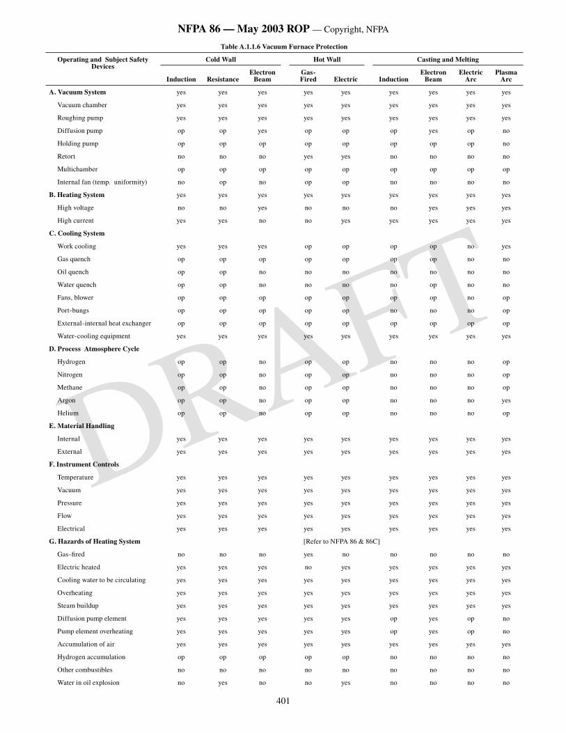
401
NFPA 86 — May 2003 ROP — Copyright, NFPA
DRAFT
Table A.1.1.6 Vacuum Furnace Protection
Operating and Subject Safety Devices
Cold Wall Hot Wall Casting and Melting
Induction ResistanceElectron
BeamGas-Fired Electric Induction
Electron Beam
Electric Arc
Plasma Arc
A. Vacuum System yes yes yes yes yes yes yes yes yes
Vacuum chamber yes yes yes yes yes yes yes yes yes
Roughing pump yes yes yes yes yes yes yes yes yes
Diffusion pump op op yes op op op yes op no
Holding pump op op op op op op op op no
Retort no no no yes yes no no no no
Multichamber op op op op op op op op op
Internal fan (temp. uniformity) no op no op op no no no no
B. Heating System yes yes yes yes yes yes yes yes yes
High voltage no no yes no no no yes yes yes
High current yes yes no no yes yes yes yes yes
C. Cooling System
Work cooling yes yes yes op op op op no yes
Gas quench op op op op op op op no no
Oil quench op op no no no no no no no
Water quench op op no no no no op no no
Fans, blower op op op op op op op no op
Port-bungs op op op op op no no no op
External-internal heat exchanger op op op op op op op op op
Water-cooling equipment yes yes yes yes yes yes yes yes yes
D. Process Atmosphere Cycle
Hydrogen op op no op op no no no op
Nitrogen op op no op op no no no op
Methane op op no op op no no no op
Argon op op no op op no no no yes
Helium op op no op op no no no op
E. Material Handling
Internal yes yes yes yes yes yes yes yes yes
External yes yes yes yes yes yes yes yes yes
F. Instrument Controls
Temperature yes yes yes yes yes yes yes yes yes
Vacuum yes yes yes yes yes yes yes yes yes
Pressure yes yes yes yes yes yes yes yes yes
Flow yes yes yes yes yes yes yes yes yes
Electrical yes yes yes yes yes yes yes yes yes
G. Hazards of Heating System [Refer to NFPA 86 & 86C]
Gas-fired no no no yes no no no no no
Electric heated yes yes yes no yes yes yes yes yes
Cooling water to be circulating yes yes yes yes yes yes yes yes yes
Overheating yes yes yes yes yes yes yes yes yes
Steam buildup yes yes yes yes yes yes yes yes yes
Diffusion pump element yes yes yes yes yes op yes op no
Pump element overheating yes yes yes yes yes op yes op no
Accumulation of air yes yes yes yes yes yes yes yes yes
Hydrogen accumulation op op op op op no no no no
Other combustibles no no no no no no no no no
Water in oil explosion no yes no no yes no no no no
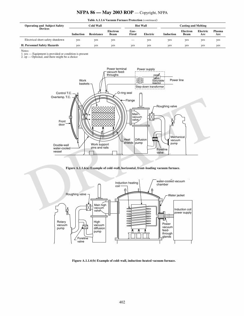
402
NFPA 86 — May 2003 ROP — Copyright, NFPA
DRAFT
Table A.1.1.6 Vacuum Furnace Protection (continued)
Operating and Subject Safety Devices
Cold Wall Hot Wall Casting and Melting
Induction ResistanceElectron
BeamGas-Fired Electric Induction
Electron Beam
Electric Arc
Plasma Arc
Electrical short safety shutdown yes yes yes — yes yes yes yes yes
H. Personnel Safety Hazards yes yes yes yes yes yes yes yes yes
Notes:1. yes — Equipment is provided or condition is present2. op — Optional, and there might be a choice
���������������������
��������������
���������������������������
������������
�������������
�����������������
������
��������������
�����������
�����������
��������������������������
����������
�����������������������������
���������������������������
����������������������������������������������
���������������������
Figure A.1.1.6(a) Example of cold-wall, horizontal, front-loading vacuum furnace.
������������������
��������������
�������������������������
����������������������
��������������
���������������������������
������������
���������������������������������������������������
����������
���������������������
�������������������������������
Figure A.1.1.6(b) Example of cold-wall, induction-heated vacuum furnace.
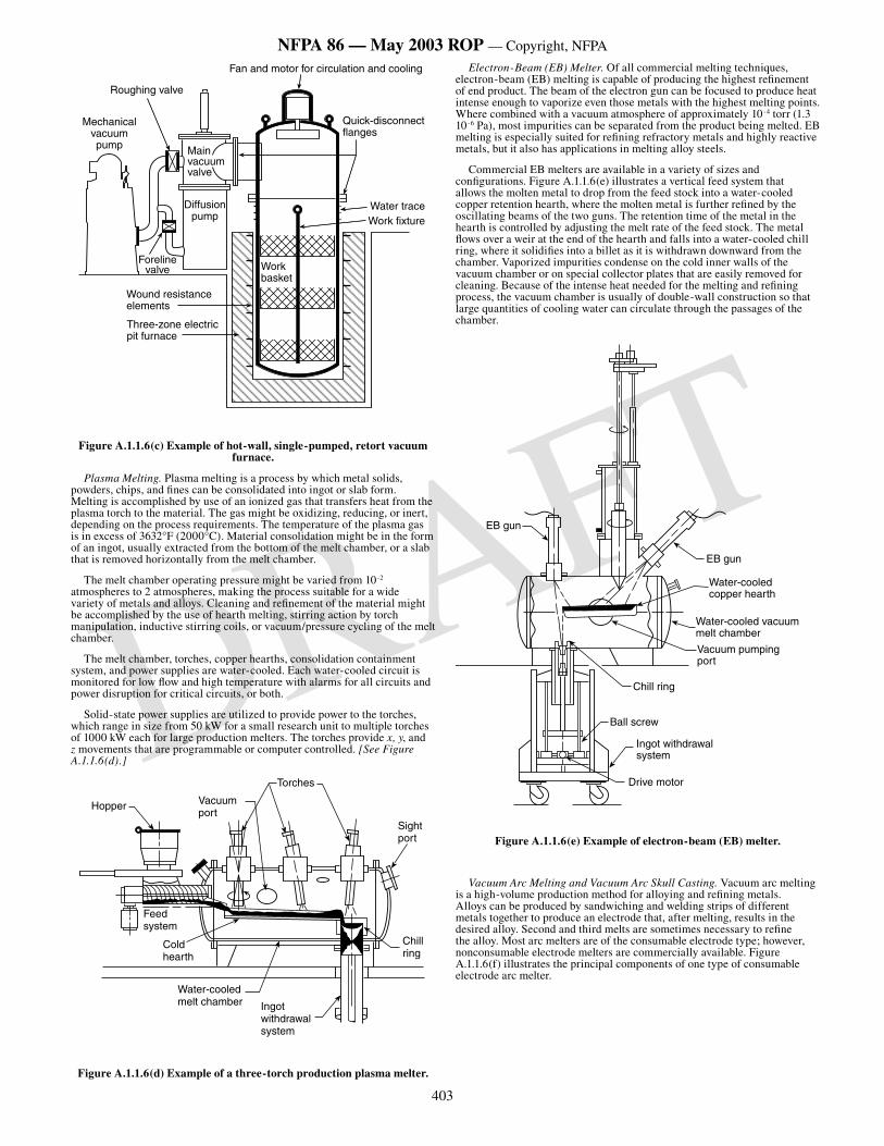
403
NFPA 86 — May 2003 ROP — Copyright, NFPA
DRAFT
�����������������
�����������������������������������������
�����������������������
�����������������������
��������������
���������������������
�������������
��������������
������������������������
������������������������������
����������
Figure A.1.1.6(c) Example of hot-wall, single-pumped, retort vacuum furnace.
Plasma Melting. Plasma melting is a process by which metal solids, powders, chips, and fines can be consolidated into ingot or slab form. Melting is accomplished by use of an ionized gas that transfers heat from the plasma torch to the material. The gas might be oxidizing, reducing, or inert, depending on the process requirements. The temperature of the plasma gas is in excess of 3632°F (2000°C). Material consolidation might be in the form of an ingot, usually extracted from the bottom of the melt chamber, or a slab that is removed horizontally from the melt chamber.
The melt chamber operating pressure might be varied from 10-2 atmospheres to 2 atmospheres, making the process suitable for a wide variety of metals and alloys. Cleaning and refinement of the material might be accomplished by the use of hearth melting, stirring action by torch manipulation, inductive stirring coils, or vacuum/pressure cycling of the melt chamber.
The melt chamber, torches, copper hearths, consolidation containment system, and power supplies are water-cooled. Each water-cooled circuit is monitored for low flow and high temperature with alarms for all circuits and power disruption for critical circuits, or both.
Solid-state power supplies are utilized to provide power to the torches, which range in size from 50 kW for a small research unit to multiple torches of 1000 kW each for large production melters. The torches provide x, y, and z movements that are programmable or computer controlled. [See Figure A.1.1.6(d).]
Hopper Vacuumport
Feed system
Cold hearth
Water-cooledmelt chamber Ingot
withdrawalsystem
Chill ring
Sight port
Torches
Figure A.1.1.6(d) Example of a three-torch production plasma melter.
Electron-Beam (EB) Melter. Of all commercial melting techniques, electron-beam (EB) melting is capable of producing the highest refinement of end product. The beam of the electron gun can be focused to produce heat intense enough to vaporize even those metals with the highest melting points. Where combined with a vacuum atmosphere of approximately 10-4 torr (1.3 10-6 Pa), most impurities can be separated from the product being melted. EB melting is especially suited for refining refractory metals and highly reactive metals, but it also has applications in melting alloy steels.
Commercial EB melters are available in a variety of sizes and configurations. Figure A.1.1.6(e) illustrates a vertical feed system that allows the molten metal to drop from the feed stock into a water-cooled copper retention hearth, where the molten metal is further refined by the oscillating beams of the two guns. The retention time of the metal in the hearth is controlled by adjusting the melt rate of the feed stock. The metal flows over a weir at the end of the hearth and falls into a water-cooled chill ring, where it solidifies into a billet as it is withdrawn downward from the chamber. Vaporized impurities condense on the cold inner walls of the vacuum chamber or on special collector plates that are easily removed for cleaning. Because of the intense heat needed for the melting and refining process, the vacuum chamber is usually of double-wall construction so that large quantities of cooling water can circulate through the passages of the chamber.
Water-cooledcopper hearth
Water-cooled vacuummelt chamber
EB gun
Vacuum pumpingport
Chill ring
Ball screw
Ingot withdrawalsystem
Drive motor
EB gun
Figure A.1.1.6(e) Example of electron-beam (EB) melter.
Vacuum Arc Melting and Vacuum Arc Skull Casting. Vacuum arc melting is a high-volume production method for alloying and refining metals. Alloys can be produced by sandwiching and welding strips of different metals together to produce an electrode that, after melting, results in the desired alloy. Second and third melts are sometimes necessary to refine the alloy. Most arc melters are of the consumable electrode type; however, nonconsumable electrode melters are commercially available. Figure A.1.1.6(f) illustrates the principal components of one type of consumable electrode arc melter.
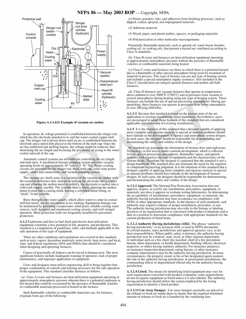
404
NFPA 86 — May 2003 ROP — Copyright, NFPA
DRAFT
Protective wall
Stinger rod (water- cooled)Control
console
OutHead
Cooling water
Electrode
Stinger rod drive cylinder (hydraulic)
In
Out
Copper melt cup
Cooling water
Power supply
Vacuumsystem
Overpressurerelief port
Head lift cylinder (hydraulic)Melted
billetPit
Figure A.1.1.6(f) Example of vacuum arc melter.
In operation, dc voltage potential is established between the stinger rod, which has the electrode attached to it, and the water-cooled copper melt cup. The stinger rod is driven down until an arc is established between the electrode and a metal disk placed in the bottom of the melt cup. Once the arc has stabilized and melting begins, the voltage might be reduced, thus shortening the arc length and lessening the possibility of arcing to the water-cooled sidewall of the cup.
Automatic control systems are available for controlling the arc length and melt rates. A mechanical booster pumping system provides vacuum operating levels of approximately 10-2 torr (1.3 10-4 Pa). Water-cooling circuits are provided for the stinger rod, head, melt cup, solid-state power supply, cables and connections, and vacuum pumping system.
The vacuum arc skull caster is a variation of the vacuum arc melter with the essential difference that, instead of melting the electrode into a copper cup and allowing the molten metal to solidify, the electrode is melted into a cold-wall copper crucible. The crucible then is tilted, allowing the molten metal to pour into a casting mold, leaving a solidified metal lining, or “skull,” in the crucible.
Burn-throughs into water jackets, which allow water to come in contact with hot metal, are not uncommon in arc melting. Equipment damage can be minimized by providing overpressure-relief ports, reliable cooling water sources, well-designed and monitored cooling circuits, and well-trained operators. Blast protection walls are frequently installed for personnel protection.
A.1.2 Explosions and fires in fuel-fired and electric heat utilization equipment constitute a loss potential in life, property, and production. This standard is a compilation of guidelines, rules, and methods applicable to the safe operation of this type of equipment.
There are other conditions and regulations not covered in this standard, such as toxic vapors; hazardous materials; noise levels; heat stress; and local, state, and federal regulations (EPA and OSHA) that should be considered when designing and operating furnaces.
Causes of practically all failures can be traced to human error. The most significant failures include inadequate training of operators, lack of proper maintenance, and improper application of equipment.
Users and designers must utilize engineering skill to bring together that proper combination of controls and training necessary for the safe operation of the equipment. This standard classifies furnaces as follows.
(a) Class A ovens and furnaces are heat utilization equipment operating at approximately atmospheric pressure wherein there is a potential explosion or fire hazard that could be occasioned by the presence of flammable volatiles or combustible materials processed or heated in the furnace.
Such flammable volatiles or combustible materials can, for instance, originate from any of the following:
(1) Paints, powders, inks, and adhesives from finishing processes, such as dipped, coated, sprayed, and impregnated materials
(2) Substrate material
(3) Wood, paper, and plastic pallets, spacers, or packaging materials
(4) Polymerization or other molecular rearrangements
Potentially flammable materials, such as quench oil, water-borne finishes, cooling oil, or cooking oils, that present a hazard are ventilated according to Class A standards.
(b) Class B ovens and furnaces are heat utilization equipment operating at approximately atmospheric pressure without the presence of flammable volatiles or combustible materials being heated.
(c) Class C ovens and furnaces are those in which there is a potential hazard due to a flammable or other special atmosphere being used for treatment of material in process. This type of furnace can use any type of heating system and includes a special atmosphere supply system(s). Also included in the Class C classification are integral quench furnaces and molten salt bath furnaces.
(d) Class D furnaces are vacuum furnaces that operate at temperatures above ambient to over 5000°F (2760°C) and at pressures from vacuum to several atmospheres during heating using any type of heating system. These furnaces can include the use of special processing atmospheres. During gas quenching, these furnaces can operate at pressures from below atmospheric to over 100 psig (690 kPa).
A.1.3.2 Because this standard is based on the present state of the art, application to existing installations is not mandatory. Nevertheless, users are encouraged to adopt those features of this standard that are considered applicable and reasonable for existing installations.
A.1.5 It is the intention of this standard that a designer capable of applying more complete and rigorous analysis to special or unusual problems should have latitude in the development of furnace and atmosphere system designs. In such cases, the designer should be responsible for demonstrating and documenting the safety and validity of the design.
No standard can guarantee the elimination of furnace fires and explosions. Technology in this area is under constant development, which is reflected in fuel, special processing atmospheres, flammable vapors, and quench systems, with regard to the type of equipment and the characteristics of the various fluids. Therefore, the designer is cautioned that the standard is not a design handbook. The standard does not eliminate the need for the engineer or competent engineering judgment. It is the intention of this standard that a designer capable of applying more complete and rigorous analysis to special or unusual problems should have latitude in the development of furnace designs. In such cases, the designer should be responsible for demonstrating and documenting the safety and validity of the design.
A.3.2.1 Approved. The National Fire Protection Association does not approve, inspect, or certify any installations, procedures, equipment, or materials; nor does it approve or evaluate testing laboratories. In determining the acceptability of installations, procedures, equipment, or materials, the authority having jurisdiction may base acceptance on compliance with NFPA or other appropriate standards. In the absence of such standards, said authority may require evidence of proper installation, procedure, or use. The authority having jurisdiction may also refer to the listings or labeling practices of an organization that is concerned with product evaluations and is thus in a position to determine compliance with appropriate standards for the current production of listed items.
A.3.2.2 Authority Having Jurisdiction (AHJ). The phrase “authority having jurisdiction,” or its acronym AHJ, is used in NFPA documents in a broad manner, since jurisdictions and approval agencies vary, as do their responsibilities. Where public safety is primary, the authority having jurisdiction may be a federal, state, local, or other regional department or individual such as a fire chief; fire marshal; chief of a fire prevention bureau, labor department, or health department; building official; electrical inspector; or others having statutory authority. For insurance purposes, an insurance inspection department, rating bureau, or other insurance company representative may be the authority having jurisdiction. In many circumstances, the property owner or his or her designated agent assumes the role of the authority having jurisdiction; at government installations, the commanding officer or departmental official may be the authority having jurisdiction.
A.3.2.4 Listed. The means for identifying listed equipment may vary for each organization concerned with product evaluation; some organizations do not recognize equipment as listed unless it is also labeled. The authority having jurisdiction should utilize the system employed by the listing organization to identify a listed product.
A.3.3.13 Cut-Away Damper. Cut-away dampers normally are placed in the exhaust or fresh air intake ducts to ensure that the required minimum amount of exhaust or fresh air is handled by the ventilating fans.
405
NFPA 86 — May 2003 ROP — Copyright, NFPA
DRAFT
A.3.3.14 Cryogenic Fluid. In the context of this standard, cryogenic fluid generally refers to gases made at low temperatures and stored at the user site in an insulated tank for use as an inert purge gas or as a atmosphere or atmosphere constituent (e.g., nitrogen, argon, carbon dioxide, hydrogen, oxygen). Cryogenic fluids must be stored and piped in vessels and piping that conform to the requirements for low temperature fluids in the applicable NFPA, CGA, ANSI, and ASME standards.
A.3.3.16 Explosion-Resistant (Radiant Tube). The radiant tube or the radiant tube heat recovery system can experience bulging and distortion but should not fail catastrophically.
A.3.3.17 Explosive Range. See NFPA 325, Guide to Fire Hazard Properties of Flammable Liquids, Gases, and Volatile Solids.
A.3.3.19 Flame Propagation Rate. This rate is a function of the temperature and the mixture conditions existing in the combustion space, burner, or piping under consideration.
A.3.3.25.3 Class A Furnace. Flammable volatiles or combustible materials can include, but are not limited to, any of the following:
(1) Paints, powders, inks, and adhesives from finishing processes, such as dipped, coated, sprayed, and impregnated materials
(2) Substrate material
(3) Wood, paper, and plastic pallets, spacers, or packaging materials
(4) Polymerization or other molecular rearrangements
In addition, potentially flammable materials, such as quench oil, water-borne finishes, cooling oil, or cooking oils, that present a hazard are ventilated according to Class A standards.
A.3.3.25.5 Class C Furnace. This type of furnace can use any type of heating system and includes a special atmosphere supply system(s). Also included in the Class C classification are integral quench furnaces and molten salt bath furnaces.
A.3.3.25.6 Class D Furnace. During inert gas quenching, Class D furnaces can operate at pressures from below atmospheric to over 100 psig (690 kPa).
A.3.3.28 Gas Quenching. This gas is recirculated over the work and through a heat exchanger by means of a fan or blower.
A.3.3.30.1 Dielectric Heater. This type of heater is useful for heating materials that commonly are thought to be nonconductive. Examples of uses include heating plastic preforms before molding, curing glue in plywood, drying rayon cakes, and other similar applications.
A.3.3.31.1 Direct-Fired Heating System. The following are different types of direct-fired heating systems:
(1) Direct-Fired, External, Nonrecirculating Heater — A direct-fired external heater arranged so that products of combustion are discharged into the oven chamber without any return or recirculation from the oven chamber [see Figure A.3.3.31.1(a)]
Figure A.3.3.31.1(a) Example of a direct-fired, external nonrecirculating heater. [Existing Figure A-2-1(a) from the 1999 edition
of NFPA 86, no change]
(2) Direct-Fired, External, Recirculating-Through Heater — A direct-fired external heater arranged so that oven atmosphere is recirculated to the oven heater and is in contact with the burner flame [See Figure AA.3.31.1(b).]
Figure A.3.3.31.1(b) Example of a direct-fired, external, recirculating-through heater. [Existing Figure A-2-1(b) from the 1999 edition of
NFPA 86, no change]
(3) Direct-Fired, Internal, Nonrecirculating Heater — A combustion chamber of a recirculating oven heater that can be permitted to be built within an oven chamber not substantially separated from the oven atmosphere by gastight construction
(4) Direct-Fired, External, Recirculating-Not-Through Heater — A heating system constructed so that the oven atmosphere circulates through a blower with products of combustion admitted to the recirculating ductwork, but without the oven atmosphere actually passing through the combustion chamber [See Figure A.3.3.31.1(c).]
Figure A.3.3.31.1(c) Example of a direct-fired, external, recirculating-not-through heater. [Existing Figure A-2-1(c) from the 1999 edition of
NFPA 86, no change]
A.3.3.31.3 Indirect Fired Internal Heating System. Radiators might be designed to withstand explosion pressures from ignition of air–fuel mixtures in the radiators.
A.3.3.31.6 Resistance Heating System. Resistance heaters can be of the open type, with bare heating conductors, or insulated sheath type, with
conductors covered by a protecting sheath that can be filled with electrical insulating material.
A.3.3.33 Implosion. Implosion can be followed by an outward scattering of pieces of the wall if the wall material is not ductile, thus causing possible danger to nearby equipment and personnel.
A.3.3.35 Limiting Oxidant Concentration (LOC). Materials other than oxygen can act as oxidants.
A.3.3.38.1 Air Jet Mixer. In some cases, this type of mixer can be designed to entrain some of the air for combustion as well as the fuel gas.
A.3.3.46.1 Low-Oxygen Oven. These ovens normally operate at high solvent levels and can operate safely in this manner by limiting the oxygen concentration within the oven enclosure.
A.3.3.54.5 Roughing Pump. The roughing pump also can be used as the backing (fore) pump for the diffusion pump, or the roughing pump can be shut off and a smaller pump can be used as the backing (fore) pump where the gas load is relatively small.
A.3.3.73 Valve Proving System. EN 1643, International Standard for Valve Proving Systems, requires leakage to be less than 1.76 ft3/hr (50 L/hr). Proof of closure definition in ANSI Z21.21/CSA 6.5, Automatic Valves for Gas Appliances, and FM 7400, Approval Standard for Liquid and Gas Safety Shut-off Valves, requires leakage less than 1 ft3/hr (28.32 L/hr).
A.4.1 Section 4.1 includes requirements for complete plans, sequence of operations, and specifications to be submitted to the authority having jurisdiction for approval. Application forms such as those in Figure A.4.1(a) and Figure A.4.1(b) can be used or might be requested to help the authority having jurisdiction in this approval process. (Variations of the forms can depend on the type of furnace or oven being furnished, its application, and the authority having jurisdiction.) Figure A.4.1(a) and Figure A.4.1(b) are two historical examples of application forms that are based on older editions of the standard. Forms consistent with current requirements should be used.
Figure A.4.1(a) Sample 1: Furnace or oven manufacturer’s application for acceptance. [Existing Figure A-1-4(a) from 1999 edition of NFPA 86,
no change]
Figure A.4.1(b) Sample 2: Furnace or oven manufacturer’s application for acceptance. [Existing Figure A-1-4(b) from 1999 edition of NFPA
86, no change]
A.4.1.1.2 Ladder-type schematic diagrams are recommended.
A.4.1.3.1 The proximity of electrical equipment and flammable gas or liquid in an electrical enclosure or panel is a known risk and would be considered a classified area. Article 500 of NFPA 70, National Electrical Code, should be consulted.
Conduit connecting devices handling flammable material might carry this material to an electrical enclosure if the device fails, creating a classified area in that enclosure. Sealing of such conduits should be considered.
A.4.1.3.3 Unless otherwise required by the local environment, ovens and furnaces and the surrounding area are not classified as a hazardous (classified) location. The primary source of ignition associated with an oven installation is the oven heating system or equipment or materials heated. The presence of these ignition sources precludes the need for imposing requirements for wiring methods appropriate for a hazardous (classified) location. Refer to Section 3.3 of NFPA 497, Recommended Practice for the Classification of Flammable Liquids, Gases, or Vapors and of Hazardous (Classified) Locations for Electrical Installations in Chemical Process Areas, and Section 3.3 of NFPA 499, Recommended Practice for the Classification of Combustible Dusts and of Hazardous (Classified) Locations for Electrical Installations in Chemical Process Areas, regarding equipment with open flames or other ignition sources.
In addition, ovens or furnaces are considered unclassified internally as proven ventilation is provided to ensure safety.
A.4.4.3 Figure A.4.4.3(a) and Figure A.4.4.3(b) relate to 4.4.3.
Figure A.4.4.3(a) Recommended manufacturer’s nameplate data. [Existing Figure A-1-7.3(a) from 1999 edition of NFPA 86, no change]
Figure A.4.4.3(b) Recommended safety design data form. [Existing Figure A-1-7.3(b) from 1993 edition of NFPA 86, no change]
A.5.1.1.1 Hazards to be considered include molten metal, salt, or other molten material spillage, quench tanks, hydraulic oil ignition, overheating of material in the furnace, and escape of fuel, processing atmospheres, or flue gases.
A.5.1.1.4 For additional information, refer to NFPA 31, Standard for the Installation of Oil-Burning Equipment; NFPA 54, National Fuel Gas Code; and NFPA 91, Standard for Exhaust Systems for Air Conveying of Vapors, Gases, Mists, and Noncombustible Particulate Solids.
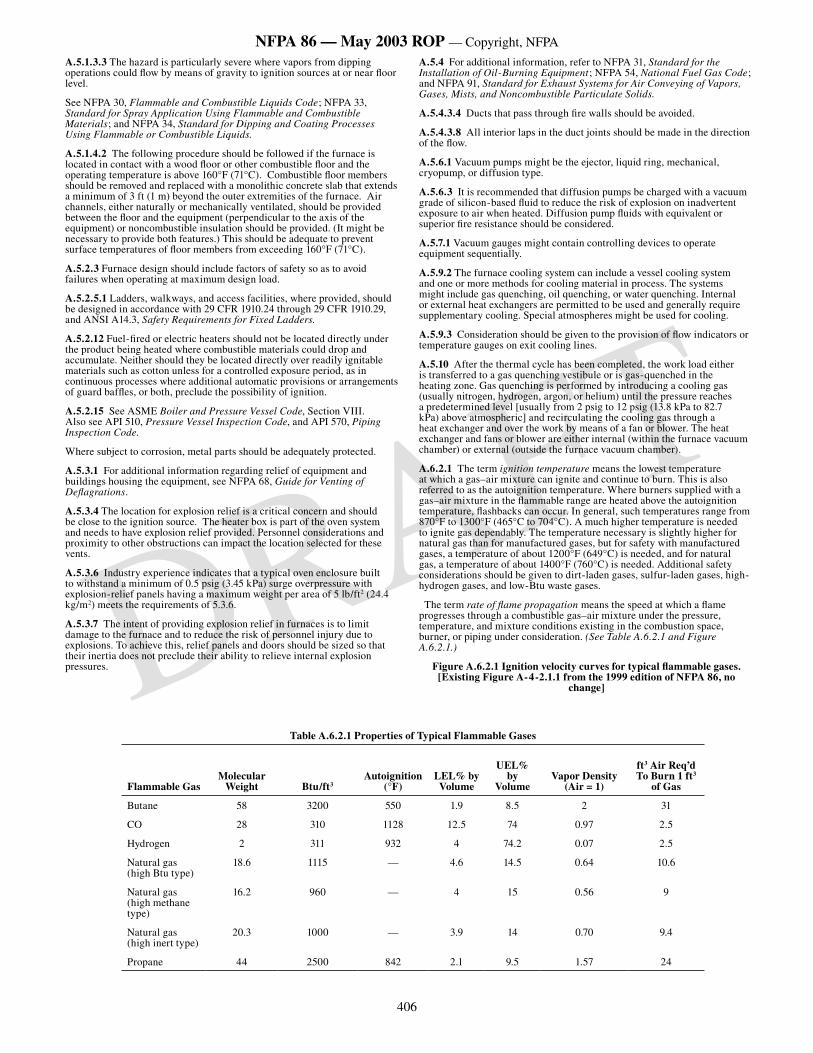
406
NFPA 86 — May 2003 ROP — Copyright, NFPA
DRAFT
A.5.1.3.3 The hazard is particularly severe where vapors from dipping operations could flow by means of gravity to ignition sources at or near floor level.
See NFPA 30, Flammable and Combustible Liquids Code; NFPA 33, Standard for Spray Application Using Flammable and Combustible Materials; and NFPA 34, Standard for Dipping and Coating Processes Using Flammable or Combustible Liquids.
A.5.1.4.2 The following procedure should be followed if the furnace is located in contact with a wood floor or other combustible floor and the operating temperature is above 160°F (71°C). Combustible floor members should be removed and replaced with a monolithic concrete slab that extends a minimum of 3 ft (1 m) beyond the outer extremities of the furnace. Air channels, either naturally or mechanically ventilated, should be provided between the floor and the equipment (perpendicular to the axis of the equipment) or noncombustible insulation should be provided. (It might be necessary to provide both features.) This should be adequate to prevent surface temperatures of floor members from exceeding 160°F (71°C).
A.5.2.3 Furnace design should include factors of safety so as to avoid failures when operating at maximum design load.
A.5.2.5.1 Ladders, walkways, and access facilities, where provided, should be designed in accordance with 29 CFR 1910.24 through 29 CFR 1910.29, and ANSI A14.3, Safety Requirements for Fixed Ladders.
A.5.2.12 Fuel-fired or electric heaters should not be located directly under the product being heated where combustible materials could drop and accumulate. Neither should they be located directly over readily ignitable materials such as cotton unless for a controlled exposure period, as in continuous processes where additional automatic provisions or arrangements of guard baffles, or both, preclude the possibility of ignition.
A.5.2.15 See ASME Boiler and Pressure Vessel Code, Section VIII. Also see API 510, Pressure Vessel Inspection Code, and API 570, Piping Inspection Code.
Where subject to corrosion, metal parts should be adequately protected.
A.5.3.1 For additional information regarding relief of equipment and buildings housing the equipment, see NFPA 68, Guide for Venting of Deflagrations.
A.5.3.4 The location for explosion relief is a critical concern and should be close to the ignition source. The heater box is part of the oven system and needs to have explosion relief provided. Personnel considerations and proximity to other obstructions can impact the location selected for these vents.
A.5.3.6 Industry experience indicates that a typical oven enclosure built to withstand a minimum of 0.5 psig (3.45 kPa) surge overpressure with explosion-relief panels having a maximum weight per area of 5 lb/ft2 (24.4 kg/m2) meets the requirements of 5.3.6.
A.5.3.7 The intent of providing explosion relief in furnaces is to limit damage to the furnace and to reduce the risk of personnel injury due to explosions. To achieve this, relief panels and doors should be sized so that their inertia does not preclude their ability to relieve internal explosion pressures.
A.5.4 For additional information, refer to NFPA 31, Standard for the Installation of Oil-Burning Equipment; NFPA 54, National Fuel Gas Code; and NFPA 91, Standard for Exhaust Systems for Air Conveying of Vapors, Gases, Mists, and Noncombustible Particulate Solids.
A.5.4.3.4 Ducts that pass through fire walls should be avoided.
A.5.4.3.8 All interior laps in the duct joints should be made in the direction of the flow.
A.5.6.1 Vacuum pumps might be the ejector, liquid ring, mechanical, cryopump, or diffusion type.
A.5.6.3 It is recommended that diffusion pumps be charged with a vacuum grade of silicon-based fluid to reduce the risk of explosion on inadvertent exposure to air when heated. Diffusion pump fluids with equivalent or superior fire resistance should be considered.
A.5.7.1 Vacuum gauges might contain controlling devices to operate equipment sequentially.
A.5.9.2 The furnace cooling system can include a vessel cooling system and one or more methods for cooling material in process. The systems might include gas quenching, oil quenching, or water quenching. Internal or external heat exchangers are permitted to be used and generally require supplementary cooling. Special atmospheres might be used for cooling.
A.5.9.3 Consideration should be given to the provision of flow indicators or temperature gauges on exit cooling lines.
A.5.10 After the thermal cycle has been completed, the work load either is transferred to a gas quenching vestibule or is gas-quenched in the heating zone. Gas quenching is performed by introducing a cooling gas (usually nitrogen, hydrogen, argon, or helium) until the pressure reaches a predetermined level [usually from 2 psig to 12 psig (13.8 kPa to 82.7 kPa) above atmospheric] and recirculating the cooling gas through a heat exchanger and over the work by means of a fan or blower. The heat exchanger and fans or blower are either internal (within the furnace vacuum chamber) or external (outside the furnace vacuum chamber).
A.6.2.1 The term ignition temperature means the lowest temperature at which a gas–air mixture can ignite and continue to burn. This is also referred to as the autoignition temperature. Where burners supplied with a gas–air mixture in the flammable range are heated above the autoignition temperature, flashbacks can occur. In general, such temperatures range from 870°F to 1300°F (465°C to 704°C). A much higher temperature is needed to ignite gas dependably. The temperature necessary is slightly higher for natural gas than for manufactured gases, but for safety with manufactured gases, a temperature of about 1200°F (649°C) is needed, and for natural gas, a temperature of about 1400°F (760°C) is needed. Additional safety considerations should be given to dirt-laden gases, sulfur-laden gases, high-hydrogen gases, and low-Btu waste gases.
The term rate of flame propagation means the speed at which a flame progresses through a combustible gas–air mixture under the pressure, temperature, and mixture conditions existing in the combustion space, burner, or piping under consideration. (See Table A.6.2.1 and Figure A.6.2.1.)
Figure A.6.2.1 Ignition velocity curves for typical flammable gases. [Existing Figure A-4-2.1.1 from the 1999 edition of NFPA 86, no
change]
Table A.6.2.1 Properties of Typical Flammable Gases
Flammable GasMolecular
Weight Btu/ft3Autoignition
(°F)LEL% by Volume
UEL% by
VolumeVapor Density
(Air = 1)
ft3 Air Req’d To Burn 1 ft3
of Gas
Butane 58 3200 550 1.9 8.5 2 31
CO 28 310 1128 12.5 74 0.97 2.5
Hydrogen 2 311 932 4 74.2 0.07 2.5
Natural gas(high Btu type)
18.6 1115 — 4.6 14.5 0.64 10.6
Natural gas(high methane type)
16.2 960 — 4 15 0.56 9
Natural gas(high inert type)
20.3 1000 — 3.9 14 0.70 9.4
Propane 44 2500 842 2.1 9.5 1.57 24
407
NFPA 86 — May 2003 ROP — Copyright, NFPA
DRAFT
A.6.2.3 For additional information, refer to NFPA 54, National Fuel Gas Code.
A.6.2.5.1.5 Lubricated plug valves require lubrication with the proper lubricant to shut off tightly. The application and type of gas used can require frequent lubrication to maintain the ability of the valve to shut off tightly when needed.
A.6.2.5.3.3 When the fuel train is opened for service, the risk of dirt entry exists. It is not required that existing piping be opened for the sole purpose of the addition of a filter or strainer.
A6.2.5.4.2 This section discusses venting of flammable and oxidizing gases only. Gases that are asphyxiants, toxic, or corrosive are outside of the scope of this standard. In this regard, other standards should be consulted for appropriate venting. Flammable gases and oxidizers should be vented to a safe location to prevent fire or explosion hazards. When gases are vented, the vent pipe should be located such that:
(1) Gas should not impinge on equipment, support, building, windows, or materials as the gas could ignite and create a fire hazard.
(2) Gas should not impinge on personnel at work in the area or in the vicinity of the exit of the vent pipe as the gas could ignite and create a fire hazard.
(3) Gas should not be vented in the vicinity of air intakes, compressor inlets, or other devices that utilize ambient air.
The vent exit should be designed such that:
(1) The pipe exit should not be subject to physical damage or foreign matter that could block the exit.
(2) The vent pipe should be sized to minimize the pressure drop associated with length, fitting and elbows at the maximum vent flow rate.
(3) The vent piping should not have any shut-off valves in the line.
If the gas is to be vented inside the building, the following addition guidance is offered:
(1) If the gas is flammable and lighter than air, then the flammable gases should be vented to a location where the gas is diluted below its lower flammable limit (LEL) before coming in contact with sources of ignition and cannot re-enter the work area without extreme dilution.
(2) If the gas is oxygen or air enriched with oxygen, then the vent gas should be vented to a location where the gas will blend with atmospheric air to a point between 19 percent and 23 percent oxygen before coming in contact withcombustibles or personnel.
A.6.2.5.4.3 See NFPA 54, National Fuel Gas Code, for exception to vent requirements.
A.6.2.7.1 In the design, fabrication, and utilization of mixture piping, it should be recognized that the air–fuel gas mixture might be in the flammable range.
A.6.2.7.3.1 Two basic methods generally are used. One method uses a separate fire check at each burner, the other a fire check at each group of burners. The second method generally is more practical if a system consists of many closely spaced burners.
A.6.2.7.3.3 Acceptable safety blowouts are available from some manufacturers of air–fuel mixing machines. They incorporate all the following components and design features:
(1) Flame arrester
(2) Blowout disk
(3) Provision for automatically shutting off the supply of air–gas mixture to the burners in the event of a flashback passing through an automatic fire check.
A.6.2.8.5 Testing of radiant tubes should include subjecting them to thermal cycling typical for the furnace application and then verifying their ability to withstand overpressure developed by a fuel–air explosion. Overpressure testing can be done in one of the following two ways:
(1) Statically pressurize the tube until it fails. Compare this pressure to the maximum pressure (from literature) that can be developed in a contained deflagration of an optimum fuel–air mixture.
(2) After partially blocking the open end of the tube to simulate a heat exchanger, fill the tube with a well-mixed stoichiometric fuel–air mixture (10 volumes of air to one volume of fuel for natural gas). Ignite the mixture at the closed end of the tube. Measure the pressure developed. Compare this pressure to the maximum pressure (from literature) that can be developed in a contained deflagration of an optimum fuel–air mixture.
A.6.2.9.1 A burner is suitably ignited when combustion of the air–fuel mixture is established and stable at the discharge port(s) of the nozzle(s) or in the contiguous combustion tunnel.
A.6.3.1 In the design and use of oil-fired units, the following should be considered.
(1) Unlike fuel gases, data on many important physical/chemical characteristics are not available for fuel oil, which, being a complex mixture of hydrocarbons, is relatively unpredictable.
(2) Fuel oil has to be vaporized prior to combustion. Heat generated by the combustion commonly is utilized for this purpose, and oil remains in the vapor phase as long as sufficient temperature is present. Under these conditions, oil vapor can be treated as fuel gas.
(3) Unlike fuel gas, oil vapor condenses into liquid when the temperature falls too low and revaporizes whenever the temperature rises to an indeterminate point. Therefore, oil in a cold furnace can lead to a hazardous condition, because, unlike fuel gas, it cannot be purged. Oil can vaporize (to become a gas) when, or because, the furnace operating temperature is reached.
(4) Unlike water, for example, there is no known established relationship between temperature and vapor pressure for fuel oil. For purposes of comparison, a gallon of fuel oil is equivalent to 140 ft3 (4.0 m3) of natural gas; therefore, 1 oz (0.03 kg) equals approximately 1 ft3 (0.03 m3).
Additional considerations that are beyond the scope of this standard should be given to other combustible liquids not specified in 6.3.1.
A.6.3.3 For additional information, refer to NFPA 31, Standard for the Installation of Oil-Burning Equipment.
A.6.3.4.4 A long circulating loop, consisting of a supply leg, a back-pressure regulating valve, and a return line back to the storage tank, is a means of reducing air entrainment.
Manual vent valves might be needed to bleed air from the high points of the oil supply piping.
A.6.3.4.6 The weight of fuel oil is always a consideration in vertical runs. When going up, pressure is lost. One hundred psig (689 kPa) with a 100-ft (30.5-m) lift nets only 63 psig (434 kPa). When going down, pressure increases. One hundred psig (689 kPa) with a 100-ft (30.5-m) drop nets 137 psig (945 kPa). This also occurs with fuel gas, but it usually is of no importance. However, it should never be overlooked where handling oils.
A.6.3.5.1.6 Lubricated plug valves require lubrication with the proper lubricant to shut off tightly. The application and type of gas used can require frequent lubrication to maintain the ability of the valve to shut off tightly when needed.
A.6.3.5.3 Customarily, a filter or strainer is installed in the supply piping to protect the pump. However, this filter or strainer mesh usually is not sufficiently fine for burner and valve protection.
A.6.3.5.5 Under some conditions, pressure sensing on fuel oil lines downstream from feed pumps can lead to gauge failure when rapid pulsation exists. A failure of the gauge can result in fuel oil leakage. The gauge should be removed from service after initial burner start-up or after periodic burner checks. An alternative approach would be to protect the gauge during service with a pressure snubber.
A.6.3.7.1 The atomizing medium might be steam, compressed air, low pressure air, air–gas mixture, fuel gas, or other gases. Atomization also might be mechanical (mechanical-atomizing tip or rotary cup).
A.6.3.9.1 A burner is suitably ignited when combustion of the air–fuel mixture is established and stable at the discharge port(s) of the nozzle(s) or in the contiguous combustion tunnel.
A.6.4.1 Oxy-fuel burners often are utilized in conjunction with arc melting furnaces to augment electric heating. Some of these burners utilize air as well. Stationary burners are attached to the furnace shell or cover, or both. Movable burners that normally are not attached to the furnace are suspended from structural members outside a furnace door. They are manipulated from the operating floor, and the oxygen and fuel are introduced into the furnace through long, concentric pipes.
Conventional flame safeguards are impractical in conjunction with oxy-fuel burners in arc furnaces because of the radio frequency noise associated with the arcs. The electric arc is a reliable means of ignition for the burners, once it has been established. After the arc has been established, the high temperatures inside an arc furnace cause the ignition of significant accumulations of oxygen and fuel.
Using oxygen to augment or to substitute for combustion air in industrial furnace heating systems presents new safety hazards for users acquainted only with air-fuel burners.
408
NFPA 86 — May 2003 ROP — Copyright, NFPA
DRAFT
One group of hazards arises from the exceptional reactivity of oxygen. It is a potent oxidizer; therefore, it accelerates burning rates. It also increases the flammability of substances that generally are considered nonflammable in air. A fire fed by oxygen is difficult to extinguish.
Special precautions are needed to prevent oxygen pipeline fires — that is, fires in which the pipe itself becomes the fuel. Designers and installers of gaseous oxygen piping should familiarize themselves with standards and guidelines referenced in this standard on pipe sizing, materials of construction, and sealing methods. Gaseous oxygen should flow at relatively low velocity in pipelines built of ferrous materials, because friction created by particles swept through steel pipe at a high speed can ignite a pipeline. For this reason, copper or copper-based alloy construction is customary where the oxygen velocity needs to be high, such as in valves, valve trim areas, and orifices.
Oxygen pipelines should be cleaned scrupulously to rid them of oil, grease, or any hydrocarbon residues before oxygen is introduced. Valves, controls, and piping elements that come in contact with oxygen should be inspected and certified as “clean for oxygen service.” Thread sealants, gaskets and seals, and valve trim should be oxygen-compatible; otherwise they could initiate or promote fires. Proven cleaning and inspection methods are described in Compressed Gas Association guidelines provided in Annex N.
Furnace operators and others who install or service oxygen piping and controls should be trained in the precautions and safe practices for handling oxygen. For example, smoking or striking a welding arc in an oxygen-enriched atmosphere could start a fire. Gaseous oxygen has no odor and is invisible, so those locations in which there is a potential for leaks are off-limits to smokers and persons doing hot work. The location of such areas should be posted. Persons who have been in contact with oxygen should be aware that their clothing is extremely flammable until it has been aired. Equipment or devices that contain oxygen should never be lubricated or cleaned with agents that are not approved for oxygen service.
Oxygen suppliers are sources of chemical material safety data sheets (MSDS) and other precautionary information for use in employee training. Users are urged to review the safety requirements in this standard and to adopt the recommendations.
Another group of hazards is created by the nature of oxy-fuel and oxygen-enriched air flames. Because they are exceptionally hot, these flames can damage the burners, ruin work in process and furnace internals, and even destroy refractory insulation that was intended for air–fuel heating. Oxygen burner systems and heating controls should have quick-acting, reliable means for controlling heat generation.
Air that has been enriched with oxygen causes fuel to ignite very easily, because added oxygen increases the flammability range of air–fuel mixtures. Therefore, preignition purging is critical where oxygen is used.
Oxygen is also a hazard for persons entering furnaces to perform inspections or repairs. Strict entry procedures for confined spaces should be implemented. They should include analyses for excess oxygen (oxygen contents in excess of 20.9 percent) in addition to the usual atmosphere tests for oxygen deficiency and flammability.
A.6.4.3.2 CGA G-4.4, Industrial Practices for Gaseous Oxygen Transmission and Distribution Piping Systems, specifies maximum gas velocity criteria, materials of construction, installation methods, joining methods, metering methods, use of filters, and specifications for oxygen-compatible sealing materials, gasket materials, and thread sealants.
A.6.4.3.3 See CGA G-4.1, Cleaning Equipment for Oxygen Service.
A.6.4.3.4 This requirement is intended to prevent the contamination of surfaces that must be clean for oxygen service from the oil normally present in plant compressed air.
A6.4.3.7 See A.6.2.5.4.2
A.6.4.3.9 See CGA G-4.4, Industrial Practices for Gaseous Oxygen Transmission and Distribution Piping Systems.
A.6.4.3.11 Commercial-grade carbon steel pipe exhibits a marked reduction in impact strength when cooled to sub-zero temperatures. Consequently, it is vulnerable to impact fracture if located downstream from a liquid oxygen vaporizer running beyond its rated vaporization capacity or at very low ambient temperatures.
A.6.4.5.2 Diffusers commonly are used to disperse oxygen into an airstream, effecting rapid and complete mixing of the oxygen into the air. High-velocity impingement of oxygen is a potential fire hazard.
A.6.6.3 Vacuum furnaces using induction, resistance, electron beam, plasma arc, or electric arc heating systems include an electric power supply with a high demand current. High-voltage supply used for electron beam, plasma arc, or ion discharge furnace units might have unique safety considerations.
A.6.6.5.2.1 Transformers should be of the dry, high fire-point or less flammable liquid type. Dry transformers should have a 270°F (150°C) rise insulation in compliance with Section 4.03 of NEMA TR 27, Commercial, Institutional and Industrial Dry-Type Transformers.
A.6.7.1 Fluid heating systems are used to heat lumber dry kilns, plywood veneer dryers, carpet ranges, textile ovens, and chemical reaction vessels. A fluid heating system typically consists of a central heat exchanger to heat the thermal fluid. Firing can be by conventional gas or oil burners. The hot gases then pass through a heat exchanger to indirectly heat the thermal fluid. The heat exchanger can be a separate, stand-alone unit or an integral part of the heater. Conventional water-tube boilers have been used as heaters, with thermal fluid replacing the water.
In addition to steam and water, special oils have been developed for this type of application, with flash points of several hundred degrees Fahrenheit. For maximum thermal efficiency, they are usually heated above their flash points, making an oil spill especially hazardous. Also, because of the high oil temperatures, it is usually necessary to keep the oil circulation through the heat exchanger at all times to prevent oil breakdown and tube fouling. Diesel-driven pumps or emergency generators are usually provided for this purpose in case of a power outage. Oil circulation can even be needed for a period of time after burner shutdown due to the residual heat in the heater.
A.6.7.2.1 Suitable relief valves should be provided where needed. Where relief valves are provided, they should be piped to a safe location. See design criteria in API RP 520 P1, Sizing, Selection, and Installation of Pressure-Relieving Devices in Refineries, Part I — Sizing and Selection, and API RP 520 P2, Sizing, Selection, and Installation of Pressure-Relieving Devices in Refineries, Part II — Installation.
A.6.7.2.3 If a combustible heat transfer fluid is used, consideration should be given to the use of automatic-actuating fire-safe isolation valves. The actuating mechanism should operate even if exposed to high temperatures. Fireproofing of the mechanism to maintain operational integrity could be necessary.
A fire-safe valve is one that provides a relatively tight valve-seat shut-off during temperatures that are high enough to destroy seals. The stem packing and gasketed body joints must also be relatively liquidtight during exposure to high temperatures.
A.6.8.1 Suitable materials generally include graphite, molybdenum, tantalum, tungsten, and others.
A.6.8.3 Where dissimilar metals are heated in contact with each other, particularly where they are oxide-free and used within a vacuum furnace, they can react and form alloys or a eutectic. The result is an alloy that melts at a considerably lower temperature than the melting points of either base metal.
Some eutectic-forming materials are listed in Table A.6.8.3 with a critical melting temperature. Operating temperatures near or above these points should be considered carefully.
Table A.6.8.3 Eutectic Melting Temperatures
Temperature
Material °F °C
Moly/nickel 2310 1266
Moly/titanium 2210 1210
Moly/carbon 2700 1482
Nickel/carbon 2310 1166
Nickel/tantalum 2450 1343
Nickel/titanium 1730 943
A.6.9 The heat energy produced by the heating elements transfers into the work principally by means of radiation and through the insulation or heat shields into the cooled walls of the vacuum vessel. The cooling medium is continually circulated through the walls of the vessel, maintaining a cold wall. Generally, water is used as the cooling medium.
A.6.9.1 Examples of proper insulation include graphite wool, alumina/silica fibers, and other materials.
A.6.9.2 Molybdenum, tantalum, tungsten, palladium, and 304/316 stainless steel are examples of acceptable metals to be used for heat shields.
A.6.9.3 Airborne material can block heat exchangers and cause vacuum valve seals to leak on furnaces that use forced gas quenching.
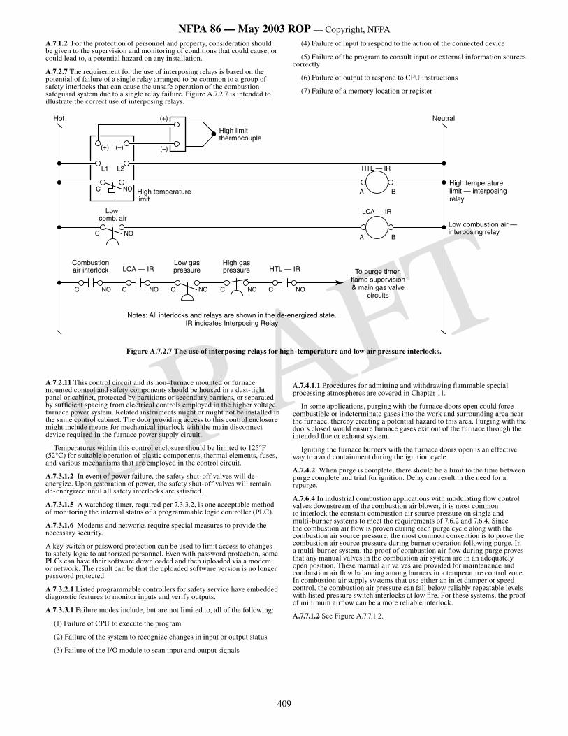
409
NFPA 86 — May 2003 ROP — Copyright, NFPA
DRAFT
A.7.1.2 For the protection of personnel and property, consideration should be given to the supervision and monitoring of conditions that could cause, or could lead to, a potential hazard on any installation.
A.7.2.7 The requirement for the use of interposing relays is based on the potential of failure of a single relay arranged to be common to a group of safety interlocks that can cause the unsafe operation of the combustion safeguard system due to a single relay failure. Figure A.7.2.7 is intended to illustrate the correct use of interposing relays.
A.7.2.11 This control circuit and its non–furnace mounted or furnace mounted control and safety components should be housed in a dust-tight panel or cabinet, protected by partitions or secondary barriers, or separated by sufficient spacing from electrical controls employed in the higher voltage furnace power system. Related instruments might or might not be installed in the same control cabinet. The door providing access to this control enclosure might include means for mechanical interlock with the main disconnect device required in the furnace power supply circuit.
Temperatures within this control enclosure should be limited to 125°F (52°C) for suitable operation of plastic components, thermal elements, fuses, and various mechanisms that are employed in the control circuit.
A.7.3.1.2 In event of power failure, the safety shut-off valves will de-energize. Upon restoration of power, the safety shut-off valves will remain de-energized until all safety interlocks are satisfied.
A.7.3.1.5 A watchdog timer, required per 7.3.3.2, is one acceptable method of monitoring the internal status of a programmable logic controller (PLC).
A.7.3.1.6 Modems and networks require special measures to provide the necessary security.
A key switch or password protection can be used to limit access to changes to safety logic to authorized personnel. Even with password protection, some PLCs can have their software downloaded and then uploaded via a modem or network. The result can be that the uploaded software version is no longer password protected.
A.7.3.2.1 Listed programmable controllers for safety service have embedded diagnostic features to monitor inputs and verify outputs.
A.7.3.3.1 Failure modes include, but are not limited to, all of the following:
(1) Failure of CPU to execute the program
(2) Failure of the system to recognize changes in input or output status
(3) Failure of the I/O module to scan input and output signals
(4) Failure of input to respond to the action of the connected device
(5) Failure of the program to consult input or external information sources correctly
(6) Failure of output to respond to CPU instructions
(7) Failure of a memory location or register
A.7.4.1.1 Procedures for admitting and withdrawing flammable special processing atmospheres are covered in Chapter 11.
In some applications, purging with the furnace doors open could force combustible or indeterminate gases into the work and surrounding area near the furnace, thereby creating a potential hazard to this area. Purging with the doors closed would ensure furnace gases exit out of the furnace through the intended flue or exhaust system.
Igniting the furnace burners with the furnace doors open is an effective way to avoid containment during the ignition cycle.
A.7.4.2 When purge is complete, there should be a limit to the time between purge complete and trial for ignition. Delay can result in the need for a repurge.
A.7.6.4 In industrial combustion applications with modulating flow control valves downstream of the combustion air blower, it is most common to interlock the constant combustion air source pressure on single and multi-burner systems to meet the requirements of 7.6.2 and 7.6.4. Since the combustion air flow is proven during each purge cycle along with the combustion air source pressure, the most common convention is to prove the combustion air source pressure during burner operation following purge. In a multi-burner system, the proof of combustion air flow during purge proves that any manual valves in the combustion air system are in an adequately open position. These manual air valves are provided for maintenance and combustion air flow balancing among burners in a temperature control zone. In combustion air supply systems that use either an inlet damper or speed control, the combustion air pressure can fall below reliably repeatable levels with listed pressure switch interlocks at low fire. For these systems, the proof of minimum airflow can be a more reliable interlock.
A.7.7.1.2 See Figure A.7.7.1.2.
������������������������
����������������� �������� ���������������
�����������������������������������
��������
�����������������������
��� ����������
��� ������
�� ��
�� ����������������������
����������������������
�������������
�
���
���
� �
��������
��������
����������������������������������������
�������������������������������������
� �
��� ��� ��� ���
���������������������������������������������������������������������������������������������������
Figure A.7.2.7 The use of interposing relays for high-temperature and low air pressure interlocks.
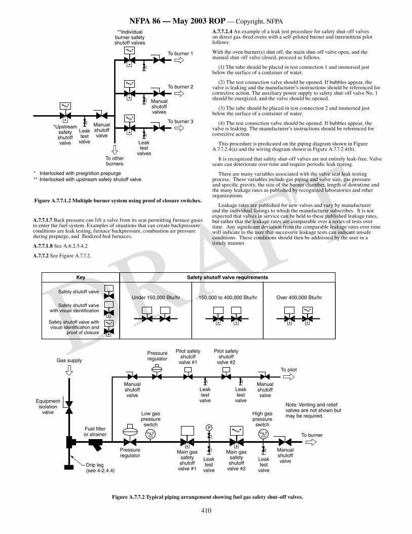
410
NFPA 86 — May 2003 ROP — Copyright, NFPA
DRAFT����������������
�������������������
���������������
�����������������������������
����������������������������������������
�� ���������������������������������������� ����������������������������������������������
�����������
��������������������
�����������
����������
������
�����������
Figure A.7.7.1.2 Multiple burner system using proof of closure switches.
A.7.7.1.7 Back pressure can lift a valve from its seat permitting furnace gases to enter the fuel system. Examples of situations that can create backpressure conditions are leak testing, furnace backpressure, combustion air pressure during prepurge, and fluidized bed furnaces.
A.7.7.1.8 See A.6.2.5.4.2
A.7.7.2 See Figure A.7.7.2.
A.7.7.2.4 An example of a leak test procedure for safety shut-off valves on direct gas-fired ovens with a self-piloted burner and intermittent pilot follows:
With the oven burner(s) shut off, the main shut-off valve open, and the manual shut-off valve closed, proceed as follows.
(1) The tube should be placed in test connection 1 and immersed just below the surface of a container of water.
(2) The test connection valve should be opened. If bubbles appear, the valve is leaking and the manufacturer’s instructions should be referenced for corrective action. The auxiliary power supply to safety shut-off valve No. 1 should be energized, and the valve should be opened.
(3) The tube should be placed in test connection 2 and immersed just below the surface of a container of water.
(4) The test connection valve should be opened. If bubbles appear, the valve is leaking. The manufacturer’s instructions should be referenced for corrective action.
This procedure is predicated on the piping diagram shown in Figure A.7.7.2.4(a) and the wiring diagram shown in Figure A.7.7.2.4(b).
It is recognized that safety shut-off valves are not entirely leak-free. Valve seats can deteriorate over time and require periodic leak testing.
There are many variables associated with the valve seat leak testing process. These variables include gas piping and valve size, gas pressure and specific gravity, the size of the burner chamber, length of downtime and the many leakage rates as published by recognized laboratories and other organizations.
Leakage rates are published for new valves and vary by manufacturer and the individual listings to which the manufacturer subscribes. It is not expected that valves in service can be held to these published leakage rates, but rather that the leakage rates are comparable over a series of tests over time. Any significant deviation from the comparable leakage rates over time will indicate to the user that successive leakage tests can indicate unsafe conditions. These conditions should then be addressed by the user in a timely manner.
�������������������������
�����������������������
������������������
������������������
��������������������
��������������������
��������������������
��������������������������������
�����������������������������
����������������������������������������
�����������������������������������������������
����������������������������������������������������
����������������
������������������������� �������������������
�����������������������������
�������������
�������������
�������������
�������������
��������������������������������
�����������������������
������������������������
����������������������
������������������������������������������������������������������
���������
��������
����������
�
Key Safety shutoff valve requirements
Figure A.7.7.2 Typical piping arrangement showing fuel gas safety shut-off valves.
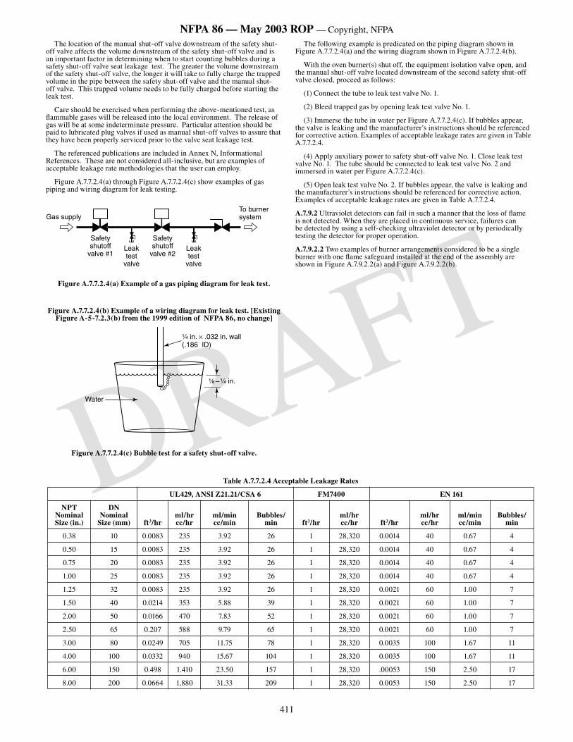
411
NFPA 86 — May 2003 ROP — Copyright, NFPA
DRAFT
The location of the manual shut-off valve downstream of the safety shut-off valve affects the volume downstream of the safety shut-off valve and is an important factor in determining when to start counting bubbles during a safety shut-off valve seat leakage test. The greater the volume downstream of the safety shut-off valve, the longer it will take to fully charge the trapped volume in the pipe between the safety shut-off valve and the manual shut-off valve. This trapped volume needs to be fully charged before starting the leak test.
Care should be exercised when performing the above-mentioned test, as flammable gases will be released into the local environment. The release of gas will be at some indeterminate pressure. Particular attention should be paid to lubricated plug valves if used as manual shut-off valves to assure that they have been properly serviced prior to the valve seat leakage test.
The referenced publications are included in Annex N, Informational References. These are not considered all-inclusive, but are examples of acceptable leakage rate methodologies that the user can employ.
Figure A.7.7.2.4(a) through Figure A.7.7.2.4(c) show examples of gas piping and wiring diagram for leak testing.
����������
�����
��������������
��������
��������������
������������������
�����
��������������������������
Figure A.7.7.2.4(a) Example of a gas piping diagram for leak test.
Figure A.7.7.2.4(b) Example of a wiring diagram for leak test. [Existing Figure A-5-7.2.3(b) from the 1999 edition of NFPA 86, no change]
¹⁄₄ in. × .032 in. wall(.186 ID)
Water
¹⁄₈ – ¹⁄₄ in.
Figure A.7.7.2.4(c) Bubble test for a safety shut-off valve.
The following example is predicated on the piping diagram shown in Figure A.7.7.2.4(a) and the wiring diagram shown in Figure A.7.7.2.4(b).
With the oven burner(s) shut off, the equipment isolation valve open, and the manual shut-off valve located downstream of the second safety shut-off valve closed, proceed as follows:
(1) Connect the tube to leak test valve No. 1.
(2) Bleed trapped gas by opening leak test valve No. 1.
(3) Immerse the tube in water per Figure A.7.7.2.4(c). If bubbles appear, the valve is leaking and the manufacturer’s instructions should be referenced for corrective action. Examples of acceptable leakage rates are given in Table A.7.7.2.4.
(4) Apply auxiliary power to safety shut-off valve No. 1. Close leak test valve No. 1. The tube should be connected to leak test valve No. 2 and immersed in water per Figure A.7.7.2.4(c).
(5) Open leak test valve No. 2. If bubbles appear, the valve is leaking and the manufacturer’s instructions should be referenced for corrective action. Examples of acceptable leakage rates are given in Table A.7.7.2.4.
A.7.9.2 Ultraviolet detectors can fail in such a manner that the loss of flame is not detected. When they are placed in continuous service, failures can be detected by using a self-checking ultraviolet detector or by periodically testing the detector for proper operation.
A.7.9.2.2 Two examples of burner arrangements considered to be a single burner with one flame safeguard installed at the end of the assembly are shown in Figure A.7.9.2.2(a) and Figure A.7.9.2.2(b).
Table A.7.7.2.4 Acceptable Leakage Rates
UL429, ANSI Z21.21/CSA 6 FM7400 EN 161
NPT Nominal Size (in.)
DN Nominal
Size (mm) ft3/hrml/hrcc/hr
ml/mincc/min
Bubbles/min ft3/hr
ml/hrcc/hr ft3/hr
ml/hrcc/hr
ml/mincc/min
Bubbles/min
0.38 10 0.0083 235 3.92 26 1 28,320 0.0014 40 0.67 4
0.50 15 0.0083 235 3.92 26 1 28,320 0.0014 40 0.67 4
0.75 20 0.0083 235 3.92 26 1 28,320 0.0014 40 0.67 4
1.00 25 0.0083 235 3.92 26 1 28,320 0.0014 40 0.67 4
1.25 32 0.0083 235 3.92 26 1 28,320 0.0021 60 1.00 7
1.50 40 0.0214 353 5.88 39 1 28,320 0.0021 60 1.00 7
2.00 50 0.0166 470 7.83 52 1 28,320 0.0021 60 1.00 7
2.50 65 0.207 588 9.79 65 1 28,320 0.0021 60 1.00 7
3.00 80 0.0249 705 11.75 78 1 28,320 0.0035 100 1.67 11
4.00 100 0.0332 940 15.67 104 1 28,320 0.0035 100 1.67 11
6.00 150 0.498 1.410 23.50 157 1 28,320 .00053 150 2.50 17
8.00 200 0.0664 1,880 31.33 209 1 28,320 0.0053 150 2.50 17
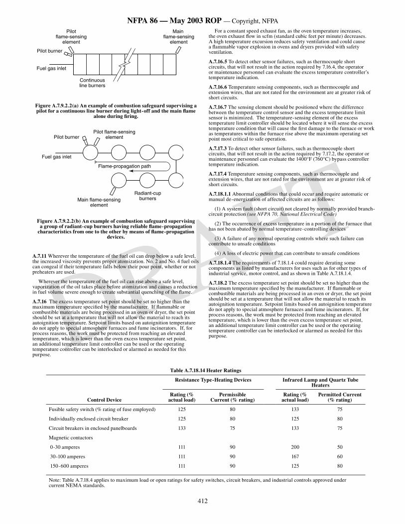
412
NFPA 86 — May 2003 ROP — Copyright, NFPA
DRAFT
Main flame-sensing
element
Pilot flame-sensing
element
Continuous line burners
Pilot burner
Fuel gas inlet
Figure A.7.9.2.2(a) An example of combustion safeguard supervising a pilot for a continuous line burner during light-off and the main flame
alone during firing.
Main flame-sensing element
Radiant-cup burners
Pilot flame-sensing element
Flame-propagation path
Pilot burner
Fuel gas inlet
Figure A.7.9.2.2(b) An example of combustion safeguard supervising a group of radiant-cup burners having reliable flame-propagation
characteristics from one to the other by means of flame-propagation devices.
A.7.11 Wherever the temperature of the fuel oil can drop below a safe level, the increased viscosity prevents proper atomization. No. 2 and No. 4 fuel oils can congeal if their temperature falls below their pour point, whether or not preheaters are used.
Wherever the temperature of the fuel oil can rise above a safe level, vaporization of the oil takes place before atomization and causes a reduction in fuel volume severe enough to create substantial quenching of the flame.
A.7.16 The excess temperature set point should be set no higher than the maximum temperature specified by the manufacturer. If flammable or combustible materials are being processed in an oven or dryer, the set point should be set at a temperature that will not allow the material to reach its autoignition temperature. Setpoint limits based on autoignition temperature do not apply to special atmosphere furnaces and fume incinerators. If, for process reasons, the work must be protected from reaching an elevated temperature, which is lower than the oven excess temperature set point, an additional temperature limit controller can be used or the operating temperature controller can be interlocked or alarmed as needed for this purpose.
For a constant speed exhaust fan, as the oven temperature increases, the oven exhaust flow in scfm (standard cubic feet per minute) decreases. A high temperature excursion reduces safety ventilation and could cause a flammable vapor explosion in ovens and dryers provided with safety ventilation.
A.7.16.5 To detect other sensor failures, such as thermocouple short circuits, that will not result in the action required by 7.16.4, the operator or maintenance personnel can evaluate the excess temperature controller’s temperature indication.
A.7.16.6 Temperature sensing components, such as thermocouple and extension wires, that are not rated for the environment are at greater risk of short circuits.
A.7.16.7 The sensing element should be positioned where the difference between the temperature control sensor and the excess temperature limit sensor is minimized. The temperature-sensing element of the excess temperature limit controller should be located where it will sense the excess temperature condition that will cause the first damage to the furnace or work as temperatures within the furnace rise above the maximum operating set point most critical to safe operation.
A.7.17.3 To detect other sensor failures, such as thermocouple short circuits, that will not result in the action required by 7.17.2, the operator or maintenance personnel can evaluate the 1400°F (760°C) bypass controller temperature indication.
A.7.17.4 Temperature sensing components, such as thermocouple and extension wires, that are not rated for the environment are at greater risk of short circuits.
A.7.18.1.1 Abnormal conditions that could occur and require automatic or manual de-energization of affected circuits are as follows:
(1) A system fault (short circuit) not cleared by normally provided branch-circuit protection (see NFPA 70, National Electrical Code)
(2) The occurrence of excess temperature in a portion of the furnace that has not been abated by normal temperature-controlling devices
(3) A failure of any normal operating controls where such failure can contribute to unsafe conditions
(4) A loss of electric power that can contribute to unsafe conditions
A.7.18.1.4 The requirements of 7.18.1.4 could require derating some components as listed by manufacturers for uses such as for other types of industrial service, motor control, and as shown in Table A.7.18.1.4.
A.7.18.2 The excess temperature set point should be set no higher than the maximum temperature specified by the manufacturer. If flammable or combustible materials are being processed in an oven or dryer, the set point should be set at a temperature that will not allow the material to reach its autoignition temperature. Setpoint limits based on autoignition temperature do not apply to special atmosphere furnaces and fume incinerators. If, for process reasons, the work must be protected from reaching an elevated temperature, which is lower than the oven excess temperature set point, an additional temperature limit controller can be used or the operating temperature controller can be interlocked or alarmed as needed for this purpose.
Table A.7.18.14 Heater Ratings
Resistance Type-Heating Devices Infrared Lamp and Quartz Tube Heaters
Control DeviceRating (%
actual load)Permissible
Current (% rating)Rating (%
actual load)Permitted Current
(% rating)
Fusible safety switch (% rating of fuse employed) 125 80 133 75
Individually enclosed circuit breaker 125 80 125 80
Circuit breakers in enclosed panelboards 133 75 133 75
Magnetic contactors
0-30 amperes 111 90 200 50
30-100 amperes 111 90 167 60
150-600 amperes 111 90 125 80
Note: Table A.7.18.4 applies to maximum load or open ratings for safety switches, circuit breakers, and industrial controls approved under current NEMA standards.
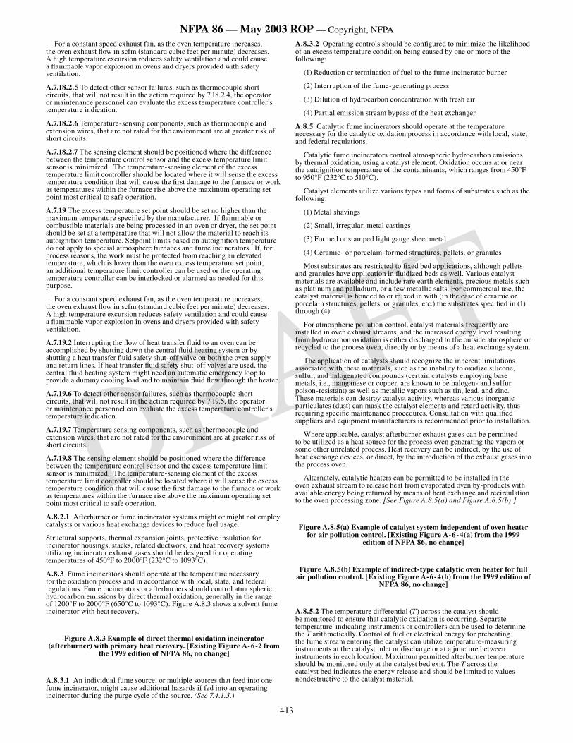
413
NFPA 86 — May 2003 ROP — Copyright, NFPA
DRAFT
For a constant speed exhaust fan, as the oven temperature increases, the oven exhaust flow in scfm (standard cubic feet per minute) decreases. A high temperature excursion reduces safety ventilation and could cause a flammable vapor explosion in ovens and dryers provided with safety ventilation.
A.7.18.2.5 To detect other sensor failures, such as thermocouple short circuits, that will not result in the action required by 7.18.2.4, the operator or maintenance personnel can evaluate the excess temperature controller’s temperature indication.
A.7.18.2.6 Temperature-sensing components, such as thermocouple and extension wires, that are not rated for the environment are at greater risk of short circuits.
A.7.18.2.7 The sensing element should be positioned where the difference between the temperature control sensor and the excess temperature limit sensor is minimized. The temperature-sensing element of the excess temperature limit controller should be located where it will sense the excess temperature condition that will cause the first damage to the furnace or work as temperatures within the furnace rise above the maximum operating set point most critical to safe operation.
A.7.19 The excess temperature set point should be set no higher than the maximum temperature specified by the manufacturer. If flammable or combustible materials are being processed in an oven or dryer, the set point should be set at a temperature that will not allow the material to reach its autoignition temperature. Setpoint limits based on autoignition temperature do not apply to special atmosphere furnaces and fume incinerators. If, for process reasons, the work must be protected from reaching an elevated temperature, which is lower than the oven excess temperature set point, an additional temperature limit controller can be used or the operating temperature controller can be interlocked or alarmed as needed for this purpose.
For a constant speed exhaust fan, as the oven temperature increases, the oven exhaust flow in scfm (standard cubic feet per minute) decreases. A high temperature excursion reduces safety ventilation and could cause a flammable vapor explosion in ovens and dryers provided with safety ventilation.
A.7.19.2 Interrupting the flow of heat transfer fluid to an oven can be accomplished by shutting down the central fluid heating system or by shutting a heat transfer fluid safety shut-off valve on both the oven supply and return lines. If heat transfer fluid safety shut-off valves are used, the central fluid heating system might need an automatic emergency loop to provide a dummy cooling load and to maintain fluid flow through the heater.
A.7.19.6 To detect other sensor failures, such as thermocouple short circuits, that will not result in the action required by 7.19.5, the operator or maintenance personnel can evaluate the excess temperature controller’s temperature indication.
A.7.19.7 Temperature sensing components, such as thermocouple and extension wires, that are not rated for the environment are at greater risk of short circuits.
A.7.19.8 The sensing element should be positioned where the difference between the temperature control sensor and the excess temperature limit sensor is minimized. The temperature-sensing element of the excess temperature limit controller should be located where it will sense the excess temperature condition that will cause the first damage to the furnace or work as temperatures within the furnace rise above the maximum operating set point most critical to safe operation.
A.8.2.1 Afterburner or fume incinerator systems might or might not employ catalysts or various heat exchange devices to reduce fuel usage.
Structural supports, thermal expansion joints, protective insulation for incinerator housings, stacks, related ductwork, and heat recovery systems utilizing incinerator exhaust gases should be designed for operating temperatures of 450°F to 2000°F (232°C to 1093°C).
A.8.3 Fume incinerators should operate at the temperature necessary for the oxidation process and in accordance with local, state, and federal regulations. Fume incinerators or afterburners should control atmospheric hydrocarbon emissions by direct thermal oxidation, generally in the range of 1200°F to 2000°F (650°C to 1093°C). Figure A.8.3 shows a solvent fume incinerator with heat recovery.
Figure A.8.3 Example of direct thermal oxidation incinerator (afterburner) with primary heat recovery. [Existing Figure A-6-2 from
the 1999 edition of NFPA 86, no change]
A.8.3.1 An individual fume source, or multiple sources that feed into one fume incinerator, might cause additional hazards if fed into an operating incinerator during the purge cycle of the source. (See 7.4.1.3.)
A.8.3.2 Operating controls should be configured to minimize the likelihood of an excess temperature condition being caused by one or more of the following:
(1) Reduction or termination of fuel to the fume incinerator burner
(2) Interruption of the fume-generating process
(3) Dilution of hydrocarbon concentration with fresh air
(4) Partial emission stream bypass of the heat exchanger
A.8.5 Catalytic fume incinerators should operate at the temperature necessary for the catalytic oxidation process in accordance with local, state, and federal regulations.
Catalytic fume incinerators control atmospheric hydrocarbon emissions by thermal oxidation, using a catalyst element. Oxidation occurs at or near the autoignition temperature of the contaminants, which ranges from 450°F to 950°F (232°C to 510°C).
Catalyst elements utilize various types and forms of substrates such as the following:
(1) Metal shavings
(2) Small, irregular, metal castings
(3) Formed or stamped light gauge sheet metal
(4) Ceramic- or porcelain-formed structures, pellets, or granules
Most substrates are restricted to fixed bed applications, although pellets and granules have application in fluidized beds as well. Various catalyst materials are available and include rare earth elements, precious metals such as platinum and palladium, or a few metallic salts. For commercial use, the catalyst material is bonded to or mixed in with (in the case of ceramic or porcelain structures, pellets, or granules, etc.) the substrates specified in (1) through (4).
For atmospheric pollution control, catalyst materials frequently are installed in oven exhaust streams, and the increased energy level resulting from hydrocarbon oxidation is either discharged to the outside atmosphere or recycled to the process oven, directly or by means of a heat exchange system.
The application of catalysts should recognize the inherent limitations associated with these materials, such as the inability to oxidize silicone, sulfur, and halogenated compounds (certain catalysts employing base metals, i.e., manganese or copper, are known to be halogen- and sulfur poison-resistant) as well as metallic vapors such as tin, lead, and zinc. These materials can destroy catalyst activity, whereas various inorganic particulates (dust) can mask the catalyst elements and retard activity, thus requiring specific maintenance procedures. Consultation with qualified suppliers and equipment manufacturers is recommended prior to installation.
Where applicable, catalyst afterburner exhaust gases can be permitted to be utilized as a heat source for the process oven generating the vapors or some other unrelated process. Heat recovery can be indirect, by the use of heat exchange devices, or direct, by the introduction of the exhaust gases into the process oven.
Alternately, catalytic heaters can be permitted to be installed in the oven exhaust stream to release heat from evaporated oven by-products with available energy being returned by means of heat exchange and recirculation to the oven processing zone. [See Figure A.8.5(a) and Figure A.8.5(b).]
Figure A.8.5(a) Example of catalyst system independent of oven heater for air pollution control. [Existing Figure A-6-4(a) from the 1999
edition of NFPA 86, no change]
Figure A.8.5(b) Example of indirect-type catalytic oven heater for full air pollution control. [Existing Figure A-6-4(b) from the 1999 edition of
NFPA 86, no change]
A.8.5.2 The temperature differential (T) across the catalyst should be monitored to ensure that catalytic oxidation is occurring. Separate temperature-indicating instruments or controllers can be used to determine the T arithmetically. Control of fuel or electrical energy for preheating the fume stream entering the catalyst can utilize temperature-measuring instruments at the catalyst inlet or discharge or at a juncture between instruments in each location. Maximum permitted afterburner temperature should be monitored only at the catalyst bed exit. The T across the catalyst bed indicates the energy release and should be limited to values nondestructive to the catalyst material.
414
NFPA 86 — May 2003 ROP — Copyright, NFPA
DRAFT
Regenerative catalyst oxidizers that employ flow reversal through the system do not produce a measurable T across the catalyst bed indicative of the energy released from the oxidation of the combustibles. In regenerative catalytic oxidation systems, the flow is reversed frequently through the system to maximize utilization of process heat. One characteristic is that the measured temperature at any one point in the system’s packed beds, whether in the heat matrix (ceramic packing) or in the catalyst bed, is never constant, rather a sinusoidal function of time. Measuring before and after the catalyst bed does not show energy released from volatile organic compound (VOC) oxidation. The fact that the catalyst bed is employed for VOC oxidation and heat recovery means that those temperatures measured are dependent on flow rate, duration between flow reversals, concentration of VOC, VOC species, activity of catalyst, and burner input.
A.8.5.3 Concentrations at 25 percent LEL can produce a temperature rise near 600°F (316°C) that, where added to the required inlet temperature, results in temperatures generally considered to be within a range where thermal degradation occurs.
In the event there is a high-temperature shutdown of the system, the catalyst bed will need to be cooled to prevent further damage of the catalyst through thermal or high-temperature breakdown. Most catalysts employ a high surface area substrate, such as alumina, that allows for the maximum amount of catalyst material exposed to the fumes per unit of catalyst (pellet, granule, or structured packing). The surface area of the catalyst can be diminished through failure of the pore structure of the substrate at elevated temperatures [typically greater than 1200°F (649°C)], which results in less exposed catalyst material per unit of catalyst and a lower activity. This rate of thermal poisoning is a function of temperature and duration, and the net effect can be minimized by quickly cooling the catalyst to safe operating temperatures, from 450°F to 950°F (232°C to 510°C).
A.8.5.4 Oxidation performance of catalyst material is a function of temperature, velocity, and pressure drop (P) through the bed, with bed size and configuration directly related to these factors. Pressure drop across the bed fluctuates with temperatures and particulate contamination. Contamination can lead to reduced safety ventilation in the upstream process.
A.8.5.5 Although the definition of a catalyst is a substance that participates in a chemical reaction without being changed by it, the reality is that catalysts are affected by chemical reactions and will lose their ability to promote the desired chemical reaction over time. In order to be sure that a catalytic fume incinerator is performing as intended, it is necessary to periodically check the activity of the catalyst. The usual method for doing this is to send a sample of the catalyst to the supplier for testing. The need for obtaining these samples should be addressed in the design of the catalyst bed.
The consequence of declining catalyst activity is the incomplete destruction of the organic vapor. Among the products of a partial combustion reaction are hydrogen, carbon monoxide, and aldehydes, all of which are flammable. The impact of significant quantities of these flammable gases on the operation of a direct heat recovery system should be assessed by the equipment supplier. Other potential concerns include the odor and skin irritation that can be caused by the aldehydes.
A.9.2.1.6 The use of propeller-type fans or blowers with forward-curved blades for applications that involve vapors that are not clean should be reviewed because of their susceptibility to accumulation of deposits and possible loss of safety ventilation.
A.9.2.1.9 Ovens using a single fan for both recirculation and exhaust are presently in use and manufactured. These dual-purpose fan installations have a long history of fire and explosion incidents. Figure A.9.2.1.9 shows examples of unacceptable safety ventilation systems.
Figure A.9.2.1.9 Unacceptable safety ventilation systems using a single fan (recirculation combined with spill exhaust). [Existing Figure A-7-2.8
from the 1999 edition of NFPA 86, no change]
A.9.2.1.13 The vapors of most volatile solvents and thinners commonly used in finishing materials are heavier than air; consequently, bottom ventilation is of prime importance [See Table 9.2.6.2.2(a) and Table 9.2.6.2.2(b)]. Liquefied petroleum gases are heavier than air, and other fuel gases are lighter than air. (See NFPA 325, Guide to Fire Hazard Properties of Flammable Liquids, Gases, and Volatile Solids. Note: Although NFPA 325 has been officially withdrawn from the National Fire Codes, the information is still available in NFPA’s Fire Protection to Hazardous Materials.)
In areas outside of the oven where volatiles are given off by material prior to entering the oven, adequate provisions should be made to exhaust vapors to the atmosphere in accordance with applicable local, state, and federal regulations.
A.9.2.3.1 The installation of any equipment can increase the pressure drop of the system and therefore reduce the combustion air flow, exhaust flow, or safety ventilation.
A.9.2.5.1 U.S. Customary Units. For example, in order to draw 9200 ft3/min of fresh air referred to 70°F (530°R) into an oven operating at 300°F (760°R), it is necessary to exhaust.
SI Units. For example, in order to draw 260 m3/min of fresh air referred to 21°C (294 K) into an oven operating at 149°C (422 K), it is necessary to exhaust.
All volumes and volumetric flow values should indicate temperature and pressure conditions [e.g., 100 ft3/min at 300°F (2.83 m3/min at 148.9°C) and ambient pressure]. [0°F (–18°C) is equivalent to 460°R (256 K)]. (See Table 9.2.5.1.)
A.9.2.5.2 Most LEL values are reported at 77°F (25°C), although several are given at 212°F (100°C). The LEL value decreases at higher temperatures, so it is necessary that the LEL value for the particular solvent be corrected for the operating temperature of the oven.
The formula used in 9.2.5.2 was originally published in Bureau of Mines Bulletin 627.
The temperature correction factor also can be expressed approximately as a 5-percent reduction in the LEL value for each 100°F (37.8°C) rise in temperature above 77°F (25°C).
A.9.2.6 Explanatory Materials and Methods for Calculating Ventilation in Various Types of Ovens. The air delivered into an oven by the supply system to do the necessary work can be all fresh air (from a source outside the oven) or it can be partly fresh air and partly recirculated air from within the oven. Only the fresh air supplied provides safety ventilation, and the amount of fresh air supplied is to be equivalent to the amount of oven exhaust air to keep the system pressure in balance. The amount of air discharged from the oven by the exhaust system is a fair indication of the safety ventilation, provided the supply and exhaust systems are designed properly. The minimum amount of fresh air delivered into the oven for safety ventilation is established by the amount of solvent vaporized from the work in process. The method for determining the minimum volume of fresh air necessary for safety ventilation is provided in A.9.2.6.2.3.
Measurement of Quantity of Air Exhausted from an Oven. A simple method to determine the quantity of air exhausted from an oven is to measure the velocity of air through the discharge duct by means of a velometer, anemometer, pitot tube, or other suitable means. This measurement then is used to calculate the volume (cubic feet or cubic meters) of air per minute by multiplying the velocity in lineal feet per minute (lineal meters per minute) by the cross-sectional area of the exhaust duct in square feet (square meters). The temperature of the exhaust air also should be measured and the calculated volume then corrected to 70°F (21°C). The resultant quantity of air is an indication of the volume exhausted from the oven, provided the exhaust air does not mix with air external to the oven. In many ovens, particularly those of the continuous type, the exhaust ducts have been incorrectly placed in locations that allow outside air to enter the exhaust system together with the ventilation air exhausted from the oven.
Problem: For continuous oven: The parts of exhaust air at 300°F (149°C) and fresh air at 70°F (21°C) that, when mixed, produce a resultant temperature of 242.5°F (117°C) are determined as follows:
(1) Temperature reading of mixed air at discharge of exhaust fan equals 242.5°F (117°C)
(2) Temperature reading of air in oven at exhaust site equals 300°F (149°C)
(3) Temperature reading of outside air at entrainment site equals 70°F (21°C)
U.S. Customary Units.
x = parts at 300°F
y = parts at 70°F
242.5 (x + y) = 300x + 70y
242.5x + 242.5y = 300x + 70y
172.5y = 57.5x
3y = x
415
NFPA 86 — May 2003 ROP — Copyright, NFPA
DRAFT
SI Units.
x = parts at 149°C
y = parts at 21°C
117 (x + y) = 149x + 21y
117x + 117y = 149x + 21y
96y = 32x
3y = x
Therefore:
3 parts at 300°F (149°C) + 1 part at 70°F (21°C) = 4 parts total at 242.5°F (117°C)
Thus, in this example, 75 percent of the air discharged by the exhaust fan is from inside the oven. Correcting this volume for 70°F (21°C) establishes the amount of 70°F (21°C) fresh air admitted into the oven.
In cases where all the fresh air admitted to the oven is through one or more openings where the volume(s) can be measured directly, it is not necessary to perform the preceding calculations.
A.9.2.6.1 Since a considerable portion of the ventilating air can pass through the oven without traversing the zone in which the majority of vapors are given off, or since uniform ventilation distribution might not exist, the 25 percent concentration level introduces a 4:1 factor of safety.
A.9.2.6.2.2 The data in these tables has been obtained from NFPA 325, Guide to Fire Hazard Properties of Flammable Liquids, Gases, and Volatile Solids, and material safety data sheets (MSDS) where available. Available figures from numerous sources vary over a wide range in many instances, depending on the purity or grade of samples and on the test conditions prescribed by different observers.
Note: Although NFPA 325 has bee officially withdrawn from the National Fire Codes, the information is still available in NFPA’s Fire Protection Guide to Hazardous Materials.
The importance of obtaining precise data on the rate of evaporation by actual tests on particular paint formulations in use needs to be emphasized. Some of these multiple component preparations might contain several solvents with widely differing values of LEL, specific gravity, and vapor density. Until such determinations are made, the operation should be on the side of safety. Therefore, the individual solvent whose data result in the largest required volume of air per gallon should be used as the basis for safe ventilation.
A.9.2.6.2.3 Theoretical Determination of Required Ventilation.
Problem: For continuous oven:
The volume of oven dilution air that would render vapor from a known volume of toluene barely flammable is determined as follows:
(1) One gallon of water weighs 8.328 lb at 70°F; one liter of water weighs 0.998 kg at 21°C.
(2) Dry air at 70°F and 29.9 in. Hg weighs 0.075 lb/ft3; dry air at 21°C and 0.76 m Hg weighs 1.200 kg/m3
(3) One cubic meter (m3) = 1000 liters (L) = 1000 cubic decimeters (dm3)
(4) Specific gravity (SpGr) of toluene = 0.87 (water = 1.0)
(5) Vapor density (VD) of toluene = 3.1 (air = 1.0)
(6) Lower explosive limit (LEL) of toluene in air = 1.1 percent by volume [see Table 9.2.6.2.2(a) and Table 9.2.6.2.2(b)] and in the LEL calculations is expressed as 1.1 (not 0.011); this value for the LEL is at standard ambient temperature of 70°F (21°C)
(7) Measured oven exhaust temperature (t) = 300°F (149°C)
(8) Corrected LEL (LELT) for oven exhaust temperature:
(See 9.2.5.2.)
U.S. Customary Units.
To determine the cubic feet (ft3) of vapor per gallon (gal) of solvent, the following calculation is used:
8 3280 075
.
./
���
������
���� �
SpGr
VDft gal at 70 F3
For this example:
8 3280 075
0 873 1
31 16..
..
.���
������
���� � ft vapor per gal of toluene at 70 F3
The LELT, being equivalent to 0.99 percent of the cubic feet of air rendered
explosive by 1 gal of toluene:
31 16100
3116.– 0.99
0.99 ft air at 70 F per gal toluene3�
������ �
Products of combustion must be added to this volume in accordance with 9.2.6.3 and then corrections made for higher oven exhaust temperature and, if applicable, for elevations of 1000 ft (305 m) or greater. An example of how these additional factors are applied can be found in A.9.2.6.4.
SI Units.
To determine the cubic meters (m3) of vapor per liter (L) of solvent, the following calculation is used:
0 9981 200
.
.
���
������
���� �
SpGr
VDm / L at 21 C3
For this example:
0 9981 200
0 873 1
.
...
���
������
���
�= 0.233 m vapor per L toluene at 21 C3
The LELT, being equivalent to 0.99 percent of the cubic meters of air
rendered explosive by 1 L of toluene:
0 233100
.– 0.99
0.99= 23.30 m air at 21 C per L toluene3�
�����
�
Products of combustion must be added to this volume in accordance with 9.2.6.3 and then corrections made for higher oven exhaust temperature and, if applicable, for elevations of 1000 ft (305 m) or greater. An example of how these additional factors are applied can be found in A.9.2.6.4.
Another Method of Computation.
For this example, xylene is to be used as the solvent.
(1) Specific gravity (SpGr) of xylene = 0.88 (water = 1.0)
(2) Molecular weight of C6H
4(CH
3)
2 = 106
(3) Lower explosive limit (LEL) of xylene in air = 0.9 percent by volume [see Table 9.2.6.2.2(a) and Table 9.2.6.2.2(b)].
(4) Corrected LEL (LELT) for oven exhaust temperature:
(LEL)(LELcf) = 0.9 [1 – 0.000784 (149°C – 25°C)] = 0.81
(See 9.2.5.2.)
(5) The molecular weight in pounds of any gas or vapor occupies 387 ft3 at 70°F and 29.9 in. of mercury. The molecular weight in grams of any gas or vapor occupies 24.1 L at 21°C and 101 kPa.
U.S. Customary Units.
Weight of 1 gal xylene:
0 888 328
.. lb H O
gal= 7.33 lb xylene / gal2�
�����
Volume of 1 gal xylene, when vaporized:
7 33. lb) (387 ft
106 molecular weight
3� �� �
416
NFPA 86 — May 2003 ROP — Copyright, NFPA
DRAFT
= 26.76 ft3 xylene vapor at standard conditions
The LELT, being equivalent to 0.81 percent of the cubic feet of air rendered
explosive by 1 gal xylene:
26 76100 0 81
0 813277.
– ..
���
���� � ft air at 70 F per gal xylene3
Products of combustion must be added to this volume in accordance with 9.2.6.3 and then corrections made for higher oven exhaust temperature and, if applicable, for elevations of 1000 ft (305 m) or greater. An example of how these additional factors are applied can be found in A.9.2.6.4.
SI Units.
Weight of 1 L xylene, when vaporized:
0 998 10000 88 878
..
kg H OL
gkg
g xylene / L2���
������
���� � �SpGr
Volume of 1 L xylene, when vaporized:
878 24 1 g L)
106 molecular weight
� �� �
( .
= 200 L xylene vapor at standard conditions
The LELT, being equivalent to 0.81 percent of the cubic meters of air
rendered explosive by 1 L xylene:
2001
L100 – 0.81
0.81 m
1000 L
3���
����
���
��
= 24.49 m3 air at 21°C per L xylene
Products of combustion must be added to this volume in accordance with 9.2.6.3 and then corrections made for higher exhaust temperature and, if applicable, for elevations of 1000 ft (305 m) or greater. An example of how these additional factors are applied can be found in A.9.2.6.4.
A.9.2.6.2.4 The basis for the general rule is that 1 gal of typical solvent produces a quantity of flammable vapor that, when diffused in air, forms approximately 2640 scf of a lean mixture that is barely explosive. One L of a typical solvent forms approximately 19.75 standard m3 of a lean mixture that is barely explosive. Refer to Table 9.2.6.2.2(a) and Table 9.2.6.2.2(b). The value of 12,000 ft3 (340 m3) includes a factor to account for LEL correction at 350°F (177°C).
A.9.2.6.4 The following method and examples demonstrate the calculation of ventilation rate for powder curing ovens:
(1) W = Maximum hourly rate of powder delivered into oven in pounds or kilograms per hour.
(2) R = Percent of powder constituents released during oven cure cycle. (An accepted value for a typical powder and operating condition is 9 percent by weight, based on experimental determination.) Thus, 0.09 lb or kg flammable constituents released per pound or kilogram of powder cured.
(3) S = Surface area of parts to be coated in square feet or square meters per hour.
(4) T = Maximum powder coating thickness in thousandths of an inch (mil) or millimeters (mm).
(5) C = Manufacturer’s recommended coverage in area per weight powder for specified thickness. Typically 1 lb of powder covers 135 ft2 to a thickness of 0.001 in. (1 mil). Typically, 1 kg of powder covers 0.70 m2 to a thickness of 1 mm.
(6) V = Volume of air rendered barely explosive per weight of powder constituent released (based on volume of air rendered barely flammable by 1 lb or 1 kg of xylene) [see Table 9.2.6.2.2(a) and Table 9.2.6.2.2(b)]. An example of V using xylene is as follows:
(7) t = oven exhaust temperature
(8) LELCF
= LEL correction factor for temperature
= 1 – [0.000436 (t°F – 77°F)]
or
= 1 – [0.000784 (t°C – 25°C)]
(9) 1 lb = 0.4536 kg
(10) 1 ft2 = 0.0929 m2
(11) 1 mil = 0.001 in. = 0.0254 mm
The calculation to establish the weight of powder entering the oven is as follows:
Dilution of powder constituents to barely explosive condition is as follows:
W R V hr
LEL 60 minCF
� � ��
1
= volume of air/min barely flammable at 70°F (21°C)
Factor of safety of 4:1 and temperature correction for oven exhaust temperature is as follows:
= volume of air/min at oven exhaust temperature
or
= volume of air/min at oven exhaust temperature
The following is a sample calculation for a direct-fired continuous powder coating oven having a 2,000,000 Btu/hr (586.2 kW) burner system used to fuse an organic powder finish on steel products at 450°F (232°C). The oven is installed at an elevation of 1000 ft (305 m) above sea level.
Surface coverage is to be 7000 ft2/hr (650 m2/hr) at a 3-mil (0.0762-mm) thickness intended to provide an average coverage of 135 ft2/lb at a 1-mil thickness or 0.702 m2/kg at a 1-mm thickness.
U.S. Customary Units.
Exhaust calculated for products of combustion (see 9.2.6.3):
Weight of powder to enter the oven:
LELCF
at 450°F:
Safety ventilation required for constituents released in oven:
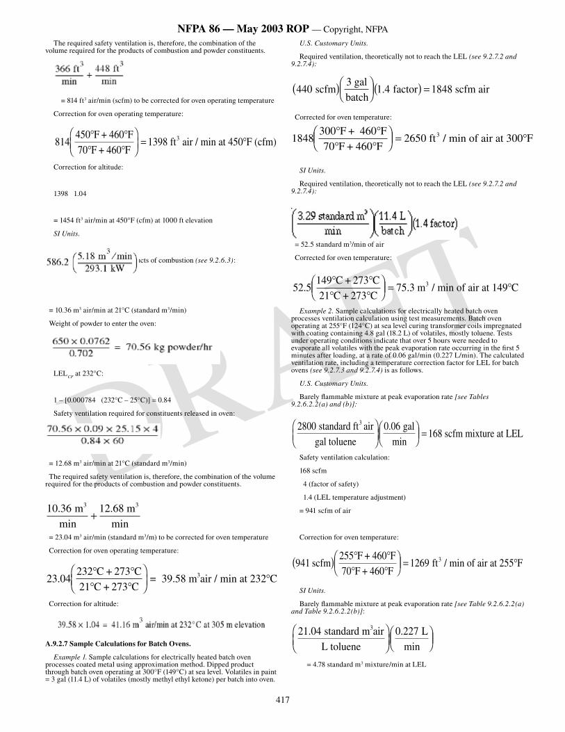
417
NFPA 86 — May 2003 ROP — Copyright, NFPA
DRAFT
The required safety ventilation is, therefore, the combination of the volume required for the products of combustion and powder constituents.
= 814 ft3 air/min (scfm) to be corrected for oven operating temperature
Correction for oven operating temperature:
814450� �
� ����
���� �
F + 460 F70 F + 460 F
1398 ft air / min at 450 F (cfm)3
Correction for altitude:
1398 1.04
= 1454 ft3 air/min at 450°F (cfm) at 1000 ft elevation
SI Units.
Exhaust calculated for products of combustion (see 9.2.6.3):
= 10.36 m3 air/min at 21°C (standard m3/min)
Weight of powder to enter the oven:
LELCF
at 232°C:
1 – [0.000784 (232°C – 25°C)] = 0.84
Safety ventilation required for constituents released in oven:
= 12.68 m3 air/min at 21°C (standard m3/min)
The required safety ventilation is, therefore, the combination of the volume required for the products of combustion and powder constituents.
10 36 12 68. . mmin
mmin
3 3
�
= 23.04 m3 air/min (standard m3/m) to be corrected for oven temperature
Correction for oven operating temperature:
23 04232
.� �� �
���
���
�C + 273 C
21 C + 273 C= 39.58 m air / min at 232 C3
Correction for altitude:
A.9.2.7 Sample Calculations for Batch Ovens.
Example 1. Sample calculations for electrically heated batch oven processes coated metal using approximation method. Dipped product through batch oven operating at 300°F (149°C) at sea level. Volatiles in paint = 3 gal (11.4 L) of volatiles (mostly methyl ethyl ketone) per batch into oven.
U.S. Customary Units.
Required ventilation, theoretically not to reach the LEL (see 9.2.7.2 and 9.2.7.4):
4403
1 4 1848 scfm gal
batch factor scfm air� ����
��� � � �.
Corrected for oven temperature:
184830070
265� �� �
���
��� � �
F + 460 FF + 460 F
0 ft min of air at 300 F3 /
SI Units.
Required ventilation, theoretically not to reach the LEL (see 9.2.7.2 and 9.2.7.4):
= 52.5 standard m3/min of air
Corrected for oven temperature:
52 5149
75 3. . /� �� �
���
��� � �
C + 273 C21 C + 273 C
m min of air at 149 C3
Example 2. Sample calculations for electrically heated batch oven processes ventilation calculation using test measurements. Batch oven operating at 255°F (124°C) at sea level curing transformer coils impregnated with coating containing 4.8 gal (18.2 L) of volatiles, mostly toluene. Tests under operating conditions indicate that over 5 hours were needed to evaporate all volatiles with the peak evaporation rate occurring in the first 5 minutes after loading, at a rate of 0.06 gal/min (0.227 L/min). The calculated ventilation rate, including a temperature correction factor for LEL for batch ovens (see 9.2.7.3 and 9.2.7.4) is as follows.
U.S. Customary Units.
Barely flammable mixture at peak evaporation rate [see Tables 9.2.6.2.2(a) and (b)]:
2800 0 06168
standard ft airgal toluene
galmin
scfm mixture at LEL3 �
��������
��� �
.
Safety ventilation calculation:
168 scfm
4 (factor of safety)
1.4 (LEL temperature adjustment)
= 941 scfm of air
Correction for oven temperature:
94125570
1269 scfmF + 460 F
F + 460 F ft min of air at 255 F3� � � �
� ����
��� � �/
SI Units.
Barely flammable mixture at peak evaporation rate [see Table 9.2.6.2.2(a) and Table 9.2.6.2.2(b)]:
21 04 0 227. . standard m airL toluene
Lmin
3���
������
���
= 4.78 standard m3 mixture/min at LEL
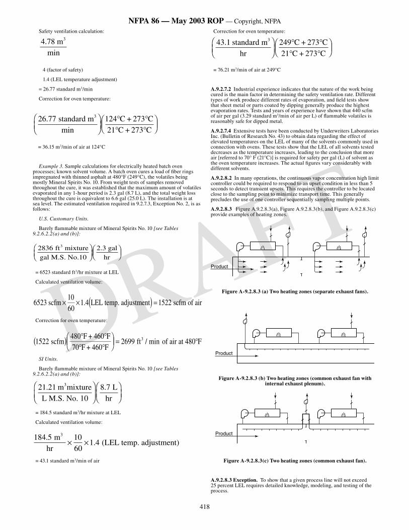
418
NFPA 86 — May 2003 ROP — Copyright, NFPA
DRAFT
Safety ventilation calculation:
4 78. mmin
3
4 (factor of safety)
1.4 (LEL temperature adjustment)
= 26.77 standard m3/min
Correction for oven temperature:
26 77 12421
. standard mmin
C + 273 CC + 273 C
3���
���
� �� �
���
���
= 36.15 m3/min of air at 124°C
Example 3. Sample calculations for electrically heated batch oven processes; known solvent volume. A batch oven cures a load of fiber rings impregnated with thinned asphalt at 480°F (249°C), the volatiles being mostly Mineral Spirits No. 10. From weight tests of samples removed throughout the cure, it was established that the maximum amount of volatiles evaporated in any 1-hour period is 2.3 gal (8.7 L), and the total weight loss throughout the cure is equivalent to 6.6 gal (25.0 L). The installation is at sea level. The estimated ventilation required in 9.2.7.3, Exception No. 2, is as follows:
U.S. Customary Units.
Barely flammable mixture of Mineral Spirits No. 10 [see Tables 9.2.6.2.2(a) and (b)]:
2836 2 3 ft mixturegal M.S. No.10
galhr
3���
������
���
.
= 6523 standard ft3/hr mixture at LEL
Calculated ventilation volume:
6523 1 4 1522 scfm1060
LEL temp. adjustment scfm of air� � � � �.
Correction for oven temperature:
1522480
2699 scfmF + 460 F
70 F + 460 F ft of air at 480 F3� � � �
� ����
��� � �/ min
SI Units.
Barely flammable mixture of Mineral Spirits No. 10 [see Tables 9.2.6.2.2(a) and (b)]:
21 21 8 7. . m mixtureL M.S. No. 10
Lhr
3�
���
�����
���
= 184.5 standard m3/hr mixture at LEL
Calculated ventilation volume:
184 5 1060
1 4.
. m
hr (LEL temp. adjustment)
3
� �
= 43.1 standard m3/min of air
Correction for oven temperature:
43 1 249. standard mhr
C + 273 C21 C + 273 C
3���
���
� �� �
���
���
= 76.21 m3/min of air at 249°C
A.9.2.7.2 Industrial experience indicates that the nature of the work being cured is the main factor in determining the safety ventilation rate. Different types of work produce different rates of evaporation, and field tests show that sheet metal or parts coated by dipping generally produce the highest evaporation rates. Tests and years of experience have shown that 440 scfm of air per gal (3.29 standard m3/min of air per L) of flammable volatiles is reasonably safe for dipped metal.
A.9.2.7.4 Extensive tests have been conducted by Underwriters Laboratories Inc. (Bulletin of Research No. 43) to obtain data regarding the effect of elevated temperatures on the LEL of many of the solvents commonly used in connection with ovens. These tests show that the LEL of all solvents tested decreases as the temperature increases, leading to the conclusion that more air [referred to 70° F (21°C)] is required for safety per gal (L) of solvent as the oven temperature increases. The actual figures vary considerably with different solvents.
A.9.2.8.2 In many operations, the continuous vapor concentration high limit controller could be required to respond to an upset condition in less than 5 seconds to detect transient upsets. This requires the controller to be located close to the sampling point to minimize transport time. This generally precludes the use of one controller sequentially sampling multiple points.
A.9.2.8.3 Figure A.9.2.8.3(a), Figure A.9.2.8.3(b), and Figure A.9.2.8.3(c) provide examples of heating zones.
Product
Figure A-9.2.8.3 (a) Two heating zones (separate exhaust fans).
Product
Figure A-9.2.8.3 (b) Two heating zones (common exhaust fan with internal exhaust plenum).
Product
Figure A-9.2.8.3(c) Two heating zones (common exhaust fan).
A.9.2.8.3 Exception. To show that a given process line will not exceed 25 percent LEL requires detailed knowledge, modeling, and testing of the process.
419
NFPA 86 — May 2003 ROP — Copyright, NFPA
DRAFT
A.9.2.8.4 When a continuous vapor concentration controller is used to modulate the flow of fresh air into or exhaust from an oven, there is a possibility that a malfunction of the controller will lead to a hazardous situation. This is why another protection system is required. The simplest form of backup is a fixed damper stop that is set so that the oven solvent concentration cannot exceed 50 percent LEL for the highest design solvent input rate. The disadvantage of the fixed damper stop is that it limits the ability of the controls to reduce the dilution air when the solvent input is low. Increased flexibility is the main advantage for using a separate continuous vapor concentration high limit controller as the system backup.
A.9.2.8.9 The sequence might include opening the exhaust and fresh air dampers, shutting down heaters, stopping the conveyor or web, stopping the coating process, and stopping or removing the coating material.
A.9.3.2.1 Low-oxygen ovens, also called inert ovens, operate safely at a much higher concentration of solvent vapor by limiting the oxygen concentration. Oxygen concentration within the appropriate equipment is kept low by the addition of an inert gas. (See Figure A.9.3.2.1.)
Figure A.9.3.2.1 An example of a low-oxygen oven with a solvent recovery system. [Existing Figure 8-1.2 from the 1999 edition of NFPA
86, no change]
A.9.3.2.2 Drying in a high solvent atmosphere facilitates recovery of solvent by condensation. The energy requirement is much lower. Drying quality and length of drying time might be improved.
A.9.3.2.3 Solvent vapors are not flammable below a certain oxygen concentration, which is different for each solvent. Annex N indicates the flammability of many solvents, and Figure A.9.3.12.2 indicates the flammable region for two common solvents.
A.9.3.2.4 This might include a condenser system, pumps, filters, tanks, level controls, and distillation equipment.
A.9.3.4.3 Ventilation should be provided at the oven openings to capture any escaping solvent vapors.
A.9.3.6.4 A flow-limiting device such as a critical flow-metering orifice, sized to limit the flow at the maximum inlet pressure, can fulfill this requirement.
A.9.3.8.3 Commercial-grade carbon steel pipe exhibits a marked reduction in impact strength when cooled to sub-zero temperatures. Consequently, it is vulnerable to impact fracture if located downstream of a vaporizer running beyond its rated vaporization capacity or at very low ambient temperature.
A.9.3.8.3 Commercial-grade carbon steel pipe exhibits a marked reduction in impact strength when cooled to sub-zero temperatures. Consequently, it is vulnerable to impact fracture if located downstream of a vaporizer running beyond its rated vaporization capacity or at very low ambient temperature.
A.9.3.9.1 The core of the safety system is the reliable monitoring of oxygen on a continuous basis, with shutdown if the oxygen level becomes too high.
A.9.3.9.3 Personnel should be provided with independent analyses of solvent and oxygen concentration before entry. (See Chapter 14 and Annex B.)
A.9.3.12.2 Figure A.9.3.12.2 relates to 9.3.12.2.
Figure A.9.3.12.2 Example of purging requirements. (Source: Bureau of Mines Bulletin 627.) [Existing Figure A-8-11.2 from the 1999 edition of
NFPA 86, no change]
A.9.3.12.4 See Section 14.2 regarding oven entry procedure and asphyxiation warnings. A check for the presence of toxic fumes should be made prior to entry.
A.9.3.14 See Section 14.2 regarding oven entry procedure and asphyxiation warnings.
A.10.2 The installation of any equipment can increase the pressure drop of the system and therefore reduce the flow rate.
A.10.3.1 Arc melting furnaces require controls normally not found on other types of electrically heated furnaces.
A.10.3.2.6 Exception. The arc, hot furnace walls, and molten metal close to the burner outlets can be considered dependable ignition sources.
A.11.1.1 A method of ensuring closure of all individual fuel gas burner valves before the main burner fuel gas safety shut-off valve can be opened is the use of a supervising cock and fuel gas safety control system. A typical piping and wiring arrangement using the pneumatic-type supervising cock is illustrated in Figure A.11.1.1(a) and Figure A.11.1.1(b). The number and
location of pressure switches, arrangement of tubing, and other details vary with the individual installation. In the figures, the main burner safety shut-off valve cannot be opened until the supervisory cocks are closed, combustion air pressure is normal, and normal fuel gas pressure is present in the pilot burner manifold. Power failure, loss of combustion air, or gas pressure failure during normal firing shuts and locks out the main burner and pilot safety shut-off valves. Once the initial check has been completed and the main burner safety shut-off valve is opened, the low fuel gas pressure switch downstream from the safety shut-off valve shuts the checking pressure switch so that, after lighting the pilots, the supervising cocks can be opened to light-off.
A typical piping and wiring arrangement for the electric interlocking-type supervising cock is also illustrated in Figure A.11.1.1(c) and Figure A.11.1.1(d). The main burner safety shut-off valve cannot be opened until all supervising cocks are closed (all valve switch contacts in series are closed), ventilation fans are operating, preventilation purge is completed, and other interlocks are satisfied.
A.11.1.1.3 See A.6.2.5.4.2.
A.11.1.2.1 The combustion reaction is self-supporting and gives off heat (that is, exothermic). The usual combustion range is from 60 percent to 100 percent of the stoichiometric ratio (aeration). In exothermic generators, the combustion products become the atmosphere gas, and, therefore, the gaseous constituents supplied to exothermic generators are called fuel gas and air.
A.11.1.2.1.2 Cuprous acetylide (Cu2C
2) is formed by exposure of acetylene
to copper in an alkaline aqueous environment. When the water is removed and the cuprous acetylide is dried out, a minor impact or frictional force will cause a violent, explosive reaction.
Acetylene is produced in small quantities in the exothermic gas-generating process. Water is a by-product of the exothermic atmosphere-generating process and, in many designs, water is used to directly cool the gas. The water can be alkaline due to many chemical influences internal or external to the gas-generating equipment.
A.11.1.3.1 The separation can be effected by use of retorts, tubes, pipes, or other special vessels. To simplify this standard, all gas used in the reaction with air to create the atmosphere is called reaction gas, and all air used in this reaction is called reaction air. Gas burned with air to supply heat is called fuel gas, and all air used with the fuel gas is called combustion air. The atmosphere produced in the generator from heating the mixture of reaction gas and reaction air is called special atmosphere gas. The reaction gas and the fuel gas might or might not be the same type of gas.
A.11.1.3.2.4 Certain system designs can require additional approved protective equipment to the reaction section, and the following components should be considered:
(1) Flow meters
(2) Meters or pressure gauges on the reaction gas and reaction air supplies
A.11.1.3.2.5 Certain system designs can require additional approved protective equipment to the endothermic generators fired with atmospheric burners, and flame safeguard devices should be considered.
A.11.1.4.3.1 Certain system designs can require additional approved protective equipment, and the following components should be considered:
(1) Flow indicators
(2) Meters
(3) Pressure gauges on reaction gas
A.11.1.5.1.5(4) For additional information, see the following Compressed Gas Association guidelines:
(1) CGA G-2, Anhydrous Ammonia
(2) CGA G-2.1, Safety Requirements for the Storage and Handling of Anhydrous Ammonia (ANSI K61.1)
(3) CGA G-5, Hydrogen
(4) CGA G-6, Carbon Dioxide
(5) CGA G-6.1, Standard for Low Pressure Carbon Dioxide Systems at Consumer Sites
(6) CGA P-1, Safe Handling of Compressed Gases in Containers
A.11.1.5.2.5 A break in the downstream pipeline or failure (opening) of the supply pressure regulator could cause excessive flow. Exceeding the capacity of an atmospheric vaporizer leads to a gradual decrease in gas temperature that can be remedied by decreasing the demand on the vaporizer.
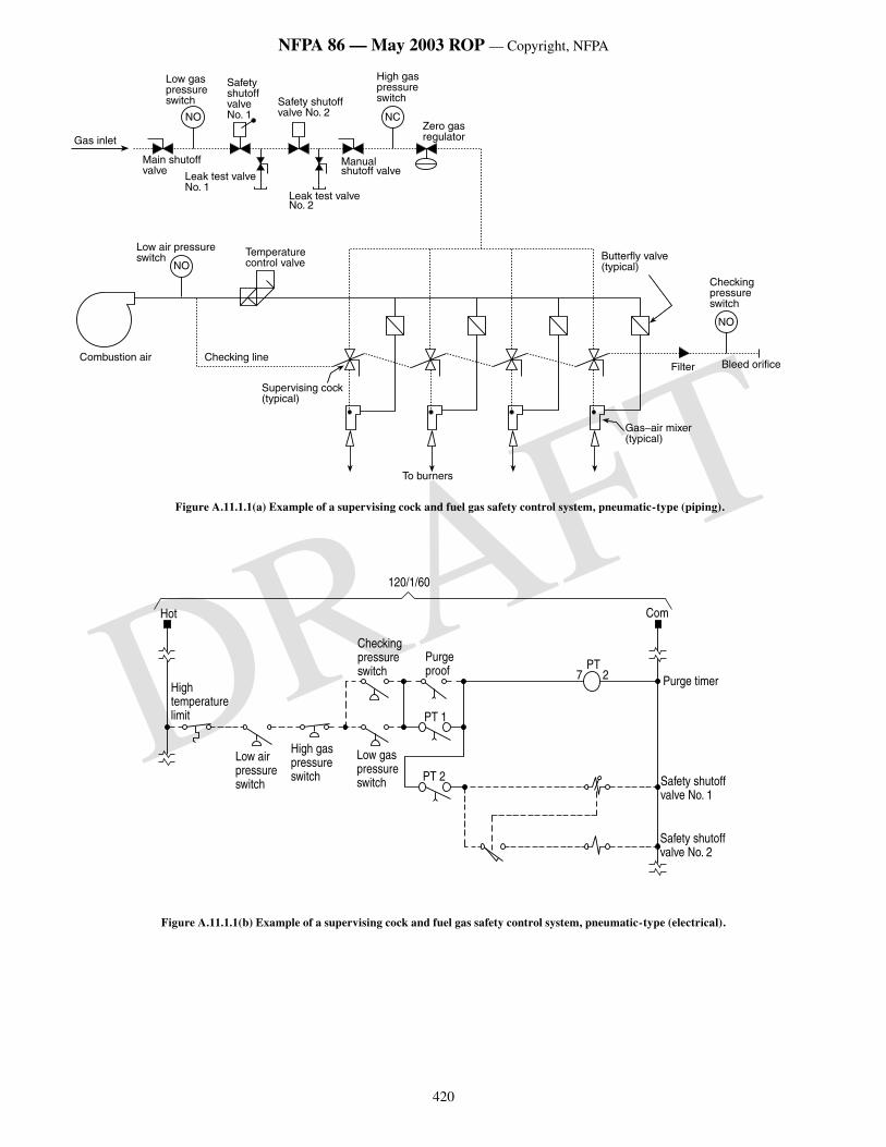
420
NFPA 86 — May 2003 ROP — Copyright, NFPA
DRAFT
Gas inlet
Low gas pressure switch
Safety shutoffvalve No. 1NO
Main shutoffvalve Leak test valve
No. 1
Safety shutoffvalve No. 2
High gas pressure switch
Zero gas regulator
NC
Manual shutoff valve
Leak test valveNo. 2
Temperaturecontrol valve
Low air pressure switch
Combustion air Checking line
Supervising cock (typical)
To burners
Gas–air mixer (typical)
Filter Bleed orifice
Checking pressure switch
Butterfly valve (typical)NO
NO
Figure A.11.1.1(a) Example of a supervising cock and fuel gas safety control system, pneumatic-type (piping).
���
���������������������
�����������������������
�����������������������
������������������������
�����������
����
����
��� � �����������
�������������������������
�������������������������
���
��������
�����������������������
Figure A.11.1.1(b) Example of a supervising cock and fuel gas safety control system, pneumatic-type (electrical).
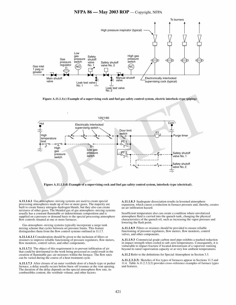
421
NFPA 86 — May 2003 ROP — Copyright, NFPA
DRAFT.
A.11.1.6.1 Gas atmosphere–mixing systems are used to create special processing atmospheres made up of two or more gases. The majority are built to create binary nitrogen–hydrogen blends, but they also can create mixtures of other gases. The blended gas of gas atmosphere–mixing systems usually has a constant flammable or indeterminate composition and is supplied on a pressure or demand basis to the special processing atmosphere flow controls situated at one or more furnaces.
Gas atmosphere–mixing systems typically incorporate a surge tank mixing scheme that cycles between set pressure limits. This feature distinguishes them from the flow control systems outlined in 11.1.7.
A.11.1.6.1.1 Consideration should be given to the inclusion of filters or strainers to improve reliable functioning of pressure regulators, flow meters, flow monitors, control valves, and other components.
A.11.1.7.1 The object of this requirement is to prevent infiltration of air that could be detrimental to the work being processed or could result in the creation of flammable gas–air mixtures within the furnace. The flow rates can be varied during the course of a heat treatment cycle.
A.11.1.7.3 After closure of an outer vestibule door of a batch-type or pusher furnace, a delay usually occurs before burn-off resumes at the vent opening. The duration of the delay depends on the special atmosphere flow rate, its combustibles content, the vestibule volume, and other factors.
A.11.1.8.3 Inadequate dissociation results in lessened atmosphere expansion, which causes a reduction in furnace pressure and, thereby, creates an air infiltration hazard.
Insufficient temperature also can create a condition where unvolatized atmosphere fluid is carried into the quench tank, changing the physical characteristics of the quench oil, such as increasing the vapor pressure and lowering the flash point.
A.11.1.8.9 Filters or strainers should be provided to ensure reliable functioning of pressure regulators, flow meters, flow monitors, control valves, and other components.
A.11.1.9.3 Commercial grade carbon steel pipe exhibits a marked reduction in impact strength when cooled to sub-zero temperatures. Consequently, it is vulnerable to impact fracture if located downstream of a vaporizer running beyond its rated vaporization capacity or at very low ambient temperatures.
A.11.2 Refer to the definitions for Special Atmosphere in Section 3.3.
A.11.2.3.2(3) Sketches of five types of furnaces appear in Sections 11.3 and 11.4. Table A.11.2.3.2(3) provides cross-reference examples of furnace types and features.
���������������������������
�����������������������
���������������������������
����������������� ���������������
�����
�������������������������
������������������������
���������������������
��
�������������������
��������������������
����������������������������������������������������
����������������������������������
����������
Figure A.11.1.1(c) Example of a supervising cock and fuel gas safety control system, electric interlock–type (piping)
���
���������������������
�����������������������
������������������������������������������
����������������������
����
��� � �����������
�������������������������
�������������������������
���
��������
����
����������������
Figure A.11.1.1(d) Example of a supervising cock and fuel gas safety control system, interlock–type (electrical).
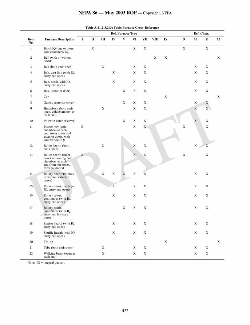
422
NFPA 86 — May 2003 ROP — Copyright, NFPA
DRAFT
Table A.11.2.3.2(3) Table Furnace Cross-Reference
Ref. Furnace Type Ref. Chap.
ItemNo.
Furnace Description I II III IV V VI VII VIII IX 9 10 11 12
1 Batch IQ (one or more cold chambers, IQ)
X X X X X
2 Bell (with or without retort)
X X X
3 Belt (both ends open) X X X X X
4 Belt, cast link (with IQ, entry end open)
X X X X X
5 Belt, mesh (with IQ, entry end open)
X X X X X
6 Box, (exterior door) X X X X X
7 Car X X
8 Gantry (exterior cover) X X X X X
9 Humpback (both ends open, cold chambers on each end)
X X X X X
10 Pit (with exterior cover) X X X X X
11 Pusher tray (cold chambers at each end, inner doors and exterior doors, with and without IQ)
X X X X X
12 Roller hearth (both ends open)
X X X X X
13 Roller hearth (inner doors separating cold chambers at each end from hot zones, external doors)
X X X X X
14 Rotary hearth (without or without exterior doors)
X X X X X X X
15 Rotary retort, batch (no IQ, entry end open)
X X X X X
16 Rotary retort, continuous (with IQ, entry end open)
X X X X X
17 Rotary retort, continuous (with IQ, entry end having a door)
X X X X X
18 Shaker hearth (with IQ, entry end open)
X X X X X
19 Shuffle hearth (with IQ, entry end open)
X X X X X
20 Tip-up X X
21 Tube (both ends open) X X X X X
22 Walking beam (open at each end)
X X X X X
Note: IQ = integral quench.
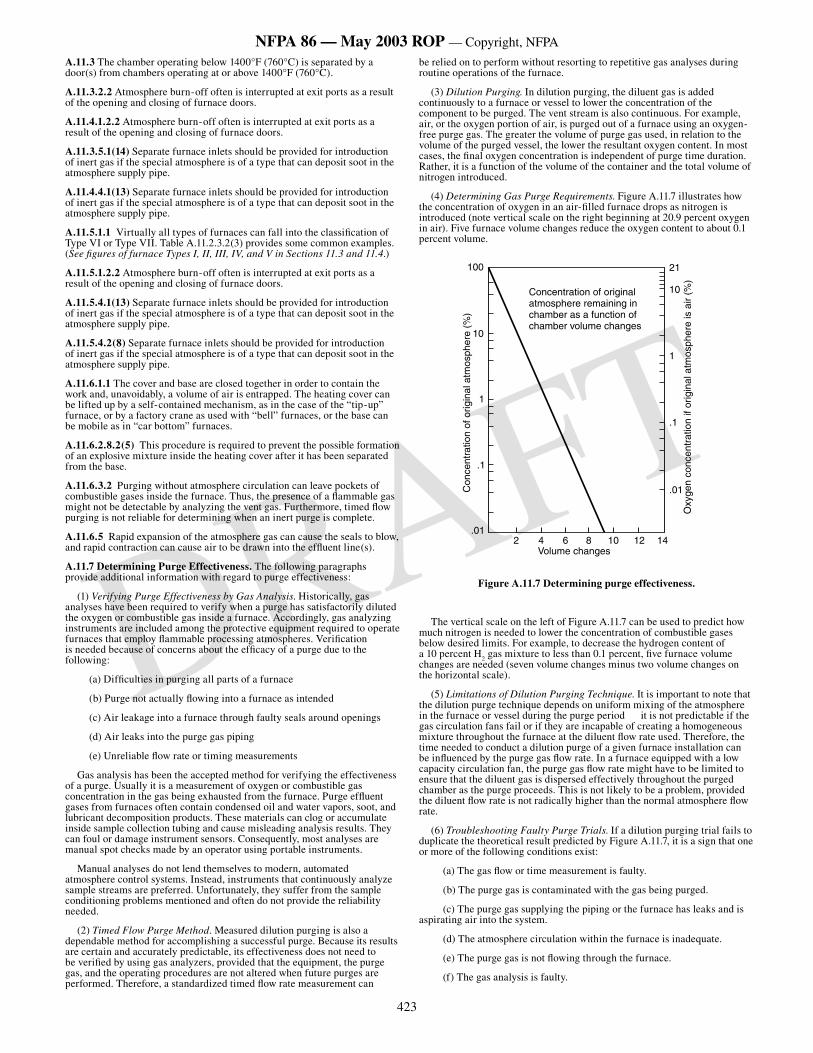
423
NFPA 86 — May 2003 ROP — Copyright, NFPA
DRAFT
A.11.3 The chamber operating below 1400°F (760°C) is separated by a door(s) from chambers operating at or above 1400°F (760°C).
A.11.3.2.2 Atmosphere burn-off often is interrupted at exit ports as a result of the opening and closing of furnace doors.
A.11.4.1.2.2 Atmosphere burn-off often is interrupted at exit ports as a result of the opening and closing of furnace doors.
A.11.3.5.1(14) Separate furnace inlets should be provided for introduction of inert gas if the special atmosphere is of a type that can deposit soot in the atmosphere supply pipe.
A.11.4.4.1(13) Separate furnace inlets should be provided for introduction of inert gas if the special atmosphere is of a type that can deposit soot in the atmosphere supply pipe.
A.11.5.1.1 Virtually all types of furnaces can fall into the classification of Type VI or Type VII. Table A.11.2.3.2(3) provides some common examples. (See figures of furnace Types I, II, III, IV, and V in Sections 11.3 and 11.4.)
A.11.5.1.2.2 Atmosphere burn-off often is interrupted at exit ports as a result of the opening and closing of furnace doors.
A.11.5.4.1(13) Separate furnace inlets should be provided for introduction of inert gas if the special atmosphere is of a type that can deposit soot in the atmosphere supply pipe.
A.11.5.4.2(8) Separate furnace inlets should be provided for introduction of inert gas if the special atmosphere is of a type that can deposit soot in the atmosphere supply pipe.
A.11.6.1.1 The cover and base are closed together in order to contain the work and, unavoidably, a volume of air is entrapped. The heating cover can be lifted up by a self-contained mechanism, as in the case of the “tip-up” furnace, or by a factory crane as used with “bell” furnaces, or the base can be mobile as in “car bottom” furnaces.
A.11.6.2.8.2(5) This procedure is required to prevent the possible formation of an explosive mixture inside the heating cover after it has been separated from the base.
A.11.6.3.2 Purging without atmosphere circulation can leave pockets of combustible gases inside the furnace. Thus, the presence of a flammable gas might not be detectable by analyzing the vent gas. Furthermore, timed flow purging is not reliable for determining when an inert purge is complete.
A.11.6.5 Rapid expansion of the atmosphere gas can cause the seals to blow, and rapid contraction can cause air to be drawn into the effluent line(s).
A.11.7 Determining Purge Effectiveness. The following paragraphs provide additional information with regard to purge effectiveness:
(1) Verifying Purge Effectiveness by Gas Analysis. Historically, gas analyses have been required to verify when a purge has satisfactorily diluted the oxygen or combustible gas inside a furnace. Accordingly, gas analyzing instruments are included among the protective equipment required to operate furnaces that employ flammable processing atmospheres. Verification is needed because of concerns about the efficacy of a purge due to the following:
(a) Difficulties in purging all parts of a furnace
(b) Purge not actually flowing into a furnace as intended
(c) Air leakage into a furnace through faulty seals around openings
(d) Air leaks into the purge gas piping
(e) Unreliable flow rate or timing measurements
Gas analysis has been the accepted method for verifying the effectiveness of a purge. Usually it is a measurement of oxygen or combustible gas concentration in the gas being exhausted from the furnace. Purge effluent gases from furnaces often contain condensed oil and water vapors, soot, and lubricant decomposition products. These materials can clog or accumulate inside sample collection tubing and cause misleading analysis results. They can foul or damage instrument sensors. Consequently, most analyses are manual spot checks made by an operator using portable instruments.
Manual analyses do not lend themselves to modern, automated atmosphere control systems. Instead, instruments that continuously analyze sample streams are preferred. Unfortunately, they suffer from the sample conditioning problems mentioned and often do not provide the reliability needed.
(2) Timed Flow Purge Method. Measured dilution purging is also a dependable method for accomplishing a successful purge. Because its results are certain and accurately predictable, its effectiveness does not need to be verified by using gas analyzers, provided that the equipment, the purge gas, and the operating procedures are not altered when future purges are performed. Therefore, a standardized timed flow rate measurement can
be relied on to perform without resorting to repetitive gas analyses during routine operations of the furnace.
(3) Dilution Purging. In dilution purging, the diluent gas is added continuously to a furnace or vessel to lower the concentration of the component to be purged. The vent stream is also continuous. For example, air, or the oxygen portion of air, is purged out of a furnace using an oxygen-free purge gas. The greater the volume of purge gas used, in relation to the volume of the purged vessel, the lower the resultant oxygen content. In most cases, the final oxygen concentration is independent of purge time duration. Rather, it is a function of the volume of the container and the total volume of nitrogen introduced.
(4) Determining Gas Purge Requirements. Figure A.11.7 illustrates how the concentration of oxygen in an air-filled furnace drops as nitrogen is introduced (note vertical scale on the right beginning at 20.9 percent oxygen in air). Five furnace volume changes reduce the oxygen content to about 0.1 percent volume.
��
��
�
��
���
�����
����
����
�����������������������
����
�������������
�
� � � � �� �� ����������������
���
��
�
��
���
����������������������������������������������������������������������������������������������
���
���������
���������
��������
����
������
�
Figure A.11.7 Determining purge effectiveness.
The vertical scale on the left of Figure A.11.7 can be used to predict how much nitrogen is needed to lower the concentration of combustible gases below desired limits. For example, to decrease the hydrogen content of a 10 percent H
2 gas mixture to less than 0.1 percent, five furnace volume
changes are needed (seven volume changes minus two volume changes on the horizontal scale).
(5) Limitations of Dilution Purging Technique. It is important to note that the dilution purge technique depends on uniform mixing of the atmosphere in the furnace or vessel during the purge period it is not predictable if the gas circulation fans fail or if they are incapable of creating a homogeneous mixture throughout the furnace at the diluent flow rate used. Therefore, the time needed to conduct a dilution purge of a given furnace installation can be influenced by the purge gas flow rate. In a furnace equipped with a low capacity circulation fan, the purge gas flow rate might have to be limited to ensure that the diluent gas is dispersed effectively throughout the purged chamber as the purge proceeds. This is not likely to be a problem, provided the diluent flow rate is not radically higher than the normal atmosphere flow rate.
(6) Troubleshooting Faulty Purge Trials. If a dilution purging trial fails to duplicate the theoretical result predicted by Figure A.11.7, it is a sign that one or more of the following conditions exist:
(a) The gas flow or time measurement is faulty.
(b) The purge gas is contaminated with the gas being purged.
(c) The purge gas supplying the piping or the furnace has leaks and is aspirating air into the system.
(d) The atmosphere circulation within the furnace is inadequate.
(e) The purge gas is not flowing through the furnace.
(f) The gas analysis is faulty.
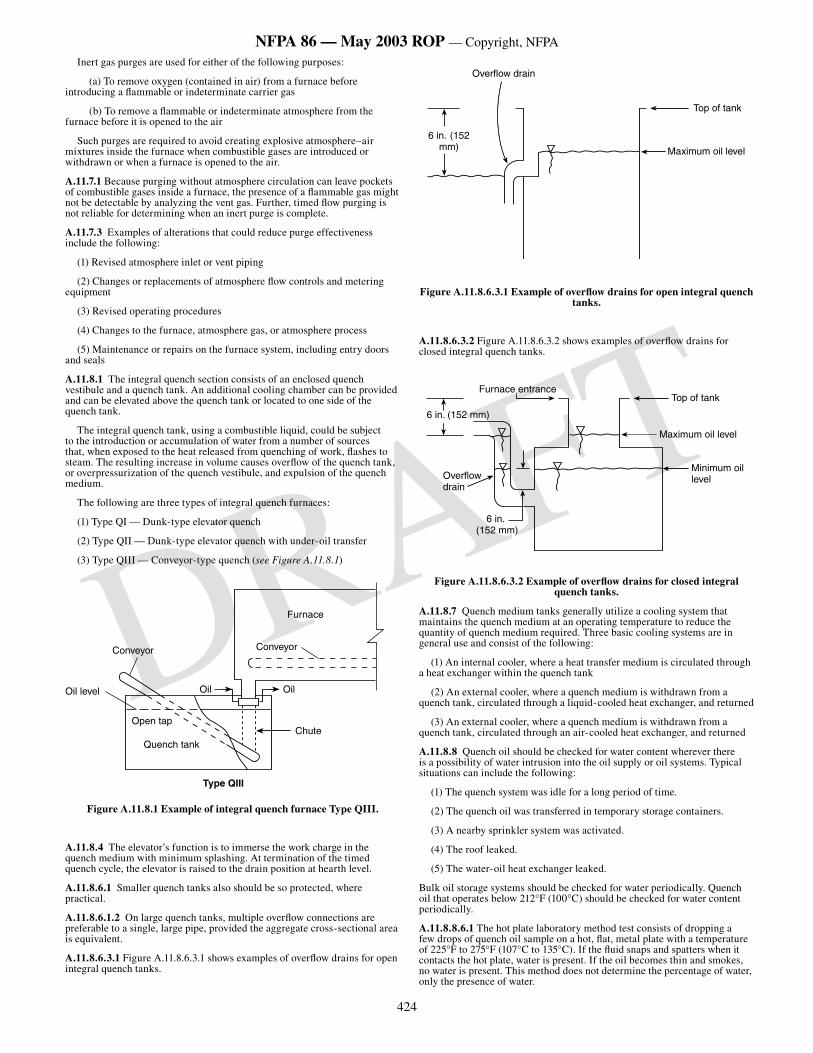
424
NFPA 86 — May 2003 ROP — Copyright, NFPA
DRAFT
Inert gas purges are used for either of the following purposes:
(a) To remove oxygen (contained in air) from a furnace before introducing a flammable or indeterminate carrier gas
(b) To remove a flammable or indeterminate atmosphere from the furnace before it is opened to the air
Such purges are required to avoid creating explosive atmosphere–air mixtures inside the furnace when combustible gases are introduced or withdrawn or when a furnace is opened to the air.
A.11.7.1 Because purging without atmosphere circulation can leave pockets of combustible gases inside a furnace, the presence of a flammable gas might not be detectable by analyzing the vent gas. Further, timed flow purging is not reliable for determining when an inert purge is complete.
A.11.7.3 Examples of alterations that could reduce purge effectiveness include the following:
(1) Revised atmosphere inlet or vent piping
(2) Changes or replacements of atmosphere flow controls and metering equipment
(3) Revised operating procedures
(4) Changes to the furnace, atmosphere gas, or atmosphere process
(5) Maintenance or repairs on the furnace system, including entry doors and seals
A.11.8.1 The integral quench section consists of an enclosed quench vestibule and a quench tank. An additional cooling chamber can be provided and can be elevated above the quench tank or located to one side of the quench tank.
The integral quench tank, using a combustible liquid, could be subject to the introduction or accumulation of water from a number of sources that, when exposed to the heat released from quenching of work, flashes to steam. The resulting increase in volume causes overflow of the quench tank, or overpressurization of the quench vestibule, and expulsion of the quench medium.
The following are three types of integral quench furnaces:
(1) Type QI — Dunk-type elevator quench
(2) Type QII — Dunk-type elevator quench with under-oil transfer
(3) Type QIII — Conveyor-type quench (see Figure A.11.8.1)
Furnace
Conveyor
Oil
Chute
Oil
Conveyor
Oil level
Open tap
Quench tank
Type QIII
Figure A.11.8.1 Example of integral quench furnace Type QIII.
A.11.8.4 The elevator’s function is to immerse the work charge in the quench medium with minimum splashing. At termination of the timed quench cycle, the elevator is raised to the drain position at hearth level.
A.11.8.6.1 Smaller quench tanks also should be so protected, where practical.
A.11.8.6.1.2 On large quench tanks, multiple overflow connections are preferable to a single, large pipe, provided the aggregate cross-sectional area is equivalent.
A.11.8.6.3.1 Figure A.11.8.6.3.1 shows examples of overflow drains for open integral quench tanks.
Top of tank
Maximum oil level
Overflow drain
6 in. (152 mm)
Figure A.11.8.6.3.1 Example of overflow drains for open integral quench tanks.
A.11.8.6.3.2 Figure A.11.8.6.3.2 shows examples of overflow drains for closed integral quench tanks.
�����������
�����������������
����������������
����������������
��������������
��������������
��������������
Figure A.11.8.6.3.2 Example of overflow drains for closed integral quench tanks.
A.11.8.7 Quench medium tanks generally utilize a cooling system that maintains the quench medium at an operating temperature to reduce the quantity of quench medium required. Three basic cooling systems are in general use and consist of the following:
(1) An internal cooler, where a heat transfer medium is circulated through a heat exchanger within the quench tank
(2) An external cooler, where a quench medium is withdrawn from a quench tank, circulated through a liquid-cooled heat exchanger, and returned
(3) An external cooler, where a quench medium is withdrawn from a quench tank, circulated through an air-cooled heat exchanger, and returned
A.11.8.8 Quench oil should be checked for water content wherever there is a possibility of water intrusion into the oil supply or oil systems. Typical situations can include the following:
(1) The quench system was idle for a long period of time.
(2) The quench oil was transferred in temporary storage containers.
(3) A nearby sprinkler system was activated.
(4) The roof leaked.
(5) The water-oil heat exchanger leaked.
Bulk oil storage systems should be checked for water periodically. Quench oil that operates below 212°F (100°C) should be checked for water content periodically.
A.11.8.8.6.1 The hot plate laboratory method test consists of dropping a few drops of quench oil sample on a hot, flat, metal plate with a temperature of 225°F to 275°F (107°C to 135°C). If the fluid snaps and spatters when it contacts the hot plate, water is present. If the oil becomes thin and smokes, no water is present. This method does not determine the percentage of water, only the presence of water.
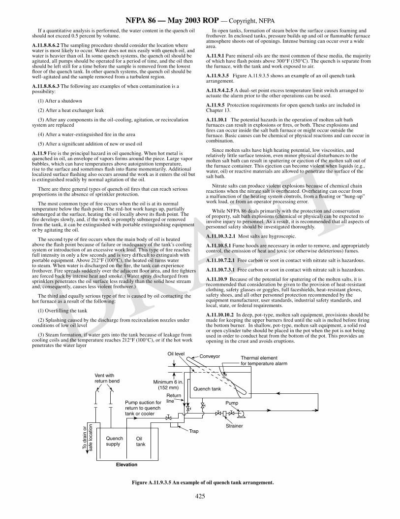
425
NFPA 86 — May 2003 ROP — Copyright, NFPA
DRAFT
If a quantitative analysis is performed, the water content in the quench oil should not exceed 0.5 percent by volume.
A.11.8.8.6.2 The sampling procedure should consider the location where water is most likely to occur. Water does not mix easily with quench oil, and water is heavier than oil. In some quench systems, the quench oil should be agitated, all pumps should be operated for a period of time, and the oil then should be left still for a time before the sample is removed from the lowest floor of the quench tank. In other quench systems, the quench oil should be well-agitated and the sample removed from a turbulent region.
A.11.8.8.6.3 The following are examples of when contamination is a possibility:
(1) After a shutdown
(2) After a heat exchanger leak
(3) After any components in the oil-cooling, agitation, or recirculation system are replaced
(4) After a water-extinguished fire in the area
(5) After a significant addition of new or used oil
A.11.9 Fire is the principal hazard in oil quenching. When hot metal is quenched in oil, an envelope of vapors forms around the piece. Large vapor bubbles, which can have temperatures above autoignition temperature, rise to the surface and sometimes flash into flame momentarily. Additional localized surface flashing also occurs around the work as it enters the oil but is extinguished readily by normal agitation of the oil.
There are three general types of quench oil fires that can reach serious proportions in the absence of sprinkler protection.
The most common type of fire occurs when the oil is at its normal temperature below the flash point. The red-hot work hangs up, partially submerged at the surface, heating the oil locally above its flash point. The fire develops slowly, and, if the work is promptly submerged or removed from the tank, it can be extinguished with portable extinguishing equipment or by agitating the oil.
The second type of fire occurs when the main body of oil is heated above the flash point because of failure or inadequacy of the tank’s cooling system or introduction of an excessive work load. This type of fire reaches full intensity in only a few seconds and is very difficult to extinguish with portable equipment. Above 212°F (100°C), the heated oil turns water to steam. When water is discharged on the fire, the tank can experience frothover. Fire spreads suddenly over the adjacent floor area, and fire fighters are forced back by intense heat and smoke. (Water spray discharged from sprinklers penetrates the oil surface less readily than the solid hose stream and, consequently, causes less violent frothover.)
The third and equally serious type of fire is caused by oil contacting the hot furnace as a result of the following:
(1) Overfilling the tank
(2) Splashing caused by the discharge from recirculation nozzles under conditions of low oil level
(3) Steam formation, if water gets into the tank because of leakage from cooling coils and the temperature reaches 212°F (100°C), or if the hot work penetrates the water layer
In open tanks, formation of steam below the surface causes foaming and frothover. In enclosed tanks, pressure builds up and oil or flammable furnace atmosphere shoots out of openings. Intense burning can occur over a wide area.
A.11.9.1 Pure mineral oils are the most common of these media, the majority of which have flash points above 300°F (150°C). The quench is separate from the furnace, with the tank and work exposed to air.
A.11.9.3.5 Figure A.11.9.3.5 shows an example of an oil quench tank arrangement.
A.11.9.4.2.5 A dual-set point excess temperature limit switch arranged to actuate the alarm prior to the other operations can be used.
A.11.9.5 Protection requirements for open quench tanks are included in Chapter 13.
A.11.10.1 The potential hazards in the operation of molten salt bath furnaces can result in explosions or fires, or both. These explosions and fires can occur inside the salt bath furnace or might occur outside the furnace. Basic causes can be chemical or physical reactions and can occur in combination.
Since molten salts have high heating potential, low viscosities, and relatively little surface tension, even minor physical disturbances to the molten salt bath can result in spattering or ejection of the molten salt out of the furnace container. This ejection can become violent when liquids (e.g., water, oil) or reactive materials are allowed to penetrate the surface of the salt bath.
Nitrate salts can produce violent explosions because of chemical chain reactions when the nitrate salt is overheated. Overheating can occur from a malfunction of the heating system controls, from a floating or “hung-up” work load, or from an operator processing error.
While NFPA 86 deals primarily with the protection and conservation of property, salt bath explosions (chemical or physical) can be expected to involve injury to personnel. As a result, it is recommended that all aspects of personnel safety should be investigated thoroughly.
A.11.10.3.2.1 Most salts are hygroscopic.
A.11.10.5.1 Fume hoods are necessary in order to remove, and appropriately control, the emission of heat and toxic (or otherwise deleterious) fumes.
A.11.10.7.2.1 Free carbon or soot in contact with nitrate salt is hazardous.
A.11.10.7.3.1 Free carbon or soot in contact with nitrate salt is hazardous.
A.11.10.9 Because of the potential for spattering of the molten salts, it is recommended that consideration be given to the provision of heat-resistant clothing, safety glasses or goggles, full faceshields, heat-resistant gloves, safety shoes, and all other personnel protection recommended by the equipment manufacturer, user standards, industrial safety standards, and local, state, or federal requirements.
A.11.10.10.2 In deep, pot-type, molten salt equipment, provisions should be made for keeping the upper burners fired until the salt is melted before firing the bottom burner. In shallow, pot-type, molten salt equipment, a solid rod or open cylinder tube should be placed in the pot when the pot is not being used in order to conduct heat from the bottom of the pot. This provides an opening in the crust and avoids eruptions.
Figure A.11.9.3.5 An example of oil quench tank arrangement.
Vent withreturn bend
ConveyorOil levelThermal elementfor temperature alarm
To d
rain
or
safe
loca
tion
Quench supply
Oil tank
Elevation
TrapStrainer
Pump
Quench tank
Pump suction forreturn to quenchtank or cooler
Return line
Minimum 6 in.(152 mm)
426
NFPA 86 — May 2003 ROP — Copyright, NFPA
DRAFT
A.12.1.2 Types of Indicating and Recording Vacuum Gauges. Monitoring pressure in the roughing line has no impact on furnace or personnel safety. However, monitoring pressure in the diffusion pump foreline is important to both equipment and personnel safety.
The calibration of all vacuum gauges should follow the standards specified by the American Vacuum Society.
Mechanical Gauges. The bellows and diaphragm mechanical gauges operate on a differential between atmospheric and process pressure. They are compensated for atmospheric pressure changes and calibrated for absolute pressure units. They are not suited for high-vacuum work, being limited to approximately 1 mm Hg (133 Pa) absolute. Readout is approximately linear except when calibrated in altitude units. Electrical output is available.
McLeod Gauge. For high-vacuum work, the McLeod gauge is often used as a primary standard for the calibration of other, more easily used instruments. The gauge is limited to intermittent sampling rather than continuous use. It operates on the principle of compressing a large known volume (V
1) of gas at unknown system pressure (P
1) into a much smaller
volume (V2) at a known higher pressure (P
2), as derived from Boyle’s Law, at
constant temperature. The gauge then is calibrated to read P1.
Thermal Gauges. The operation of a thermal gauge is based on the theory that energy dissipated from a hot surface is proportional to the pressure of the surrounding gas. Some manufacturers produce thermal gauges that are subject to contamination by vaporized materials, and this issue should be discussed with the gauge manufacturer. The following are types of thermal gauges:
(1) Thermocouple Gauge. The thermocouple gauge contains a V-shaped filament with a small thermocouple attached to the point. At low absolute pressures, the cooling effect on the heated filament is proportional to the pressure of the surrounding gas. Therefore, the thermocouple electromagnetic field (emf) can be used to indicate pressure. In order to compensate for ambient temperature, an identical second unit is sealed in an evacuated tube. The differential output of the two thermocouples is proportional to the pressure.
(2) Pirani Gauge. The Pirani gauge employs a Wheatstone bridge circuit. This circuit balances the resistance of a tungsten filament sealed off in high vacuum against that of a tungsten filament that can lose heat to the gas being measured by means of conduction. In the Pirani gauge, the resistance of the filament, rather than its temperature, is used as an indication of pressure.
(3) Bimetal Gauge. A bimetallic spiral is heated by a stabilized power source. Any change of pressure causes a change of temperature and, therefore, a deflection of the spiral, which is linked to a pointer on a scale that indicates pressure.
Ionization Gauges. The two types of ionization gauges are the hot filament (hot cathode) gauge and the cold cathode (Phillips or discharge) gauge. Their principle of operation is based on the fact that collisions between molecules and electrons result in the formation of ions. The rate of ion formation varies directly with pressure. Measurement of the ion current can be translated into units of gas pressure. The two types of ionization gauges are as follows:
(1) Hot Filament Gauge. This gauge is constructed like an electron tube. It has a tungsten filament surrounded by a coil grid, which, in turn, is surrounded by a collector plate. Electrons emitted from the heated filament are accelerated toward the positively charged coil grid. The accelerated electrons pass through the coil grid into the space between the grid and the negatively charged collector plate. Some electrons collide with gas molecules from the vacuum system to produce positive ions. The positive current is a function of the number of ions formed and, therefore, is a measure of the pressure of the system.
Ionization gauge-sensing elements are extremely delicate and should be handled carefully. Their filaments can burn out if accidentally exposed to pressures above 1 10-3 mm Hg (1.3 10-1 Pa) absolute. The advantages of this type of gauge are high sensitivity and the ability to measure extremely high vacuums.
(2) Cold Cathode Gauge. A cold cathode gauge employs the principle of the measurement of an ion current produced by a discharge of high voltage. Electrons from the cathode of the sensing element are caused to spiral as they move across a magnetic field to the anode. With this spiraling, the electron mean-free path greatly exceeds the distance between electrodes. Therefore, the possibility of a collision with the gas molecules present is increased, producing greater sensitivity (due to greater ion current) and thus sustaining the cathode discharge at lower pressure (i.e., high vacuum).
The sensing elements are rugged and are well-suited to production applications where unskilled help might make filament burnout a problem.
A.12.1.4 This would help prevent pump oil or air from passing through the system or causing damage to the furnace or load.
A.12.1.6 An example label reads as follows: Do not open oil drain or fill plugs for service until pump heater is at room temperature. Otherwise,
ignition of pump oil can occur with rapid expansion of gas, causing damage to the pump and furnace hot zone.
A.12.1.7.1 The formation of steam pockets can cause an explosion.
A.12.1.7.2 If the electron beam becomes fixed on one spot, burn-through of a water circuit could occur.
A.12.1.7.5 Accelerating voltages can run as high as 100 KV and present a shock or x-ray hazard.
A.12.2.1 Integral liquid quench systems might be constructed within the furnace vacuum chamber or might be in quench vestibules separated from the heating portion of the chamber with a door or vacuum-tight valve. Semicontinuous furnaces employ valves on each end of the hot vacuum zone. These furnaces might be divided into three separate chambers: a loading vestibule, a hot vacuum chamber, and a cooling vestibule. With this arrangement, cooling or pressurizing the hot vacuum chamber is not required for loading and unloading. Cooling vestibules are often equipped with elevators so that loads can be quenched by either vacuum, gas, or oil.
A.12.2.2.2 Although carbon steel plate has been used for many years with water cooling, its use is now not permitted, because corrosion is continuous and its extent is difficult to determine. In existing installations where carbon steel has been used with water-based coolants, the wall thickness should be tested periodically to determine the corrosion rate and predict the remaining life.
A.12.2.4.1 Quench medium tanks generally utilize a cooling system to maintain the quench medium at an operating temperature to reduce the quantity of quench media required. Three basic cooling systems are in general use and consist of the following:
(1) Internal cooler, where a heat transfer medium is circulated through a heat exchanger within the quench tank
(2) External cooler, where a quench medium is withdrawn from a quench tank, circulated through a water-cooled heat exchanger, and returned
(3) External cooler, where a quench medium is withdrawn from a quench tank, circulated through an air-cooled heat exchanger, and returned
A.12.2.4.2.2 Maximum working pressure should include allowance for vacuum conditions.
A.12.2.4.3.2 Maximum working pressure should include allowance for vacuum conditions.
A.12.2.6.10.1 The hot plate laboratory method test consists of dropping a few drops of quench oil sample on a hot, flat, metal plate with a temperature of 225° F to 275° F (107° C to 135° C). If the fluid snaps and spatters when it contacts the hot plate, water is present. If the oil becomes thin and smokes, no water is present. This method does not determine the percentage of water, only the presence of water. If a quantitative analysis of the water is performed, the water content of the oil should not exceed 0.5 percent by volume.
A.12.2.6.10.2 The sampling procedure should consider the location where water is most likely to occur. Water does not mix easily with quench oil, and water is heavier than oil. In some quench systems, the quench oil should be agitated, all pumps should be operated for a period of time, and the oil then should be left still for a time before the sample is removed from the lowest floor of the quench tank. In other quench systems, the quench oil should be well agitated and the sample removed from a turbulent region.
A.12.2.6.10.3 The following are examples of when contamination is a possibility:
(1) After a shutdown
(2) After a heat exchanger leak
(3) After any components in the oil-cooling, agitation, or recirculation system are replaced
(4) After a water-extinguished fire in the area
(5) After a significant addition of new or used oil
A.12.3.1.1 The LEL for hydrogen is 4 percent in air. This represents a pressure of 30 torr (3.9 kPa). In the interest of safety, a lower limit of one-half of this pressure [15 torr (1.9 kPa)] has been used. Other gases have other LELs. (See Annex M.)
A.12.3.1.2 Flammable gaseous hydrocarbons, dissociated ammonia, and hydrogen are frequently employed either at pressures below atmosphere or slightly above atmosphere, which should be considered in the design of the furnace.
General. Chemical vapor deposition (CVD) is a process of reacting gaseous constituents to form a film on a surface. It can be used to produce thin films, thick films, or monolithic structures. In a typical CVD process,
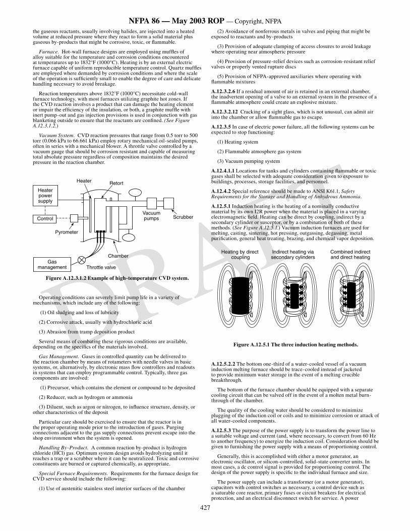
427
NFPA 86 — May 2003 ROP — Copyright, NFPA
DRAFT
the gaseous reactants, usually involving halides, are injected into a heated volume at reduced pressure where they react to form a solid material plus gaseous by-products that might be corrosive, toxic, or flammable.
Furnace. Hot-wall furnace designs are employed using muffles of alloy suitable for the temperature and corrosion conditions encountered at temperatures up to 1832°F (1000°C). Heating is by an external electric furnace capable of uniform reproducible temperature control. Quartz muffles are employed where demanded by corrosion conditions and where the scale of the operation is sufficiently small to enable the degree of care and delicate handling necessary to avoid breakage.
Reaction temperatures above 1832°F (1000°C) necessitate cold-wall furnace technology, with most furnaces utilizing graphite hot zones. If the CVD reaction involves a product that can damage the heating element or impair the efficiency of the insulation, or both, a graphite muffle with inert pump-out and gas injection provisions is used in conjunction with gas blanketing outside to ensure that the reactants are confined. (See Figure A.12.3.1.2.)
Vacuum System. CVD reaction pressures that range from 0.5 torr to 500 torr (0.066 kPa to 66.661 kPa) employ rotary mechanical oil-sealed pumps, often in series with a mechanical blower. A throttle valve controlled by a vacuum gauge that should be corrosion resistant and capable of measuring total absolute pressure regardless of composition maintains the desired pressure in the reaction chamber.
Heater power supply
Control
Gas management Throttle valve
Chamber
ScrubberVacuumpumps
RetortHeater
Pyrometer
Figure A.12.3.1.2 Example of high-temperature CVD system.
Operating conditions can severely limit pump life in a variety of mechanisms, which include any of the following:
(1) Oil sludging and loss of lubricity
(2) Corrosive attack, usually with hydrochloric acid
(3) Abrasion from tramp deposition product
Several means of combating these rigorous conditions are available, depending on the specifics of the materials involved.
Gas Management. Gases in controlled quantity can be delivered to the reaction chamber by means of rotameters with needle valves in basic systems, or, alternatively, by electronic mass flow controllers and readouts in systems that can employ programmable control. Typically, three gas components are involved:
(1) Precursor, which contains the element or compound to be deposited
(2) Reducer, such as hydrogen or ammonia
(3) Diluent, such as argon or nitrogen, to influence structure, density, or other characteristics of the deposit
Particular care should be exercised to ensure that the reactor is in the proper operating mode prior to the introduction of gases. Purging connections adjacent to the gas supply connections prevent escape into the shop environment when the system is opened.
Handling By-Product. A common reaction by-product is hydrogen chloride (HCl) gas. Optimum system design avoids hydrolyzing until it reaches a trap or a scrubber where it can be neutralized. Toxic and corrosive constituents are burned or captured chemically, as appropriate.
Special Furnace Requirements. Requirements for the furnace design for CVD service should include the following:
(1) Use of austenitic stainless steel interior surfaces of the chamber
(2) Avoidance of nonferrous metals in valves and piping that might be exposed to reactants and by-products
(3) Provision of adequate clamping of access closures to avoid leakage where operating near atmospheric pressure
(4) Provision of pressure-relief devices such as corrosion-resistant relief valves or properly vented rupture discs
(5) Provision of NFPA-approved auxiliaries where operating with flammable mixtures
A.12.3.2.6 If a residual amount of air is retained in an external chamber, the inadvertent opening of a valve to an external system in the presence of a flammable atmosphere could create an explosive mixture.
A.12.3.2.12 Cracking of a sight glass, which is not unusual, can admit air into the chamber or allow flammable gas to escape.
A.12.3.5 In case of electric power failure, all the following systems can be expected to stop functioning:
(1) Heating system
(2) Flammable atmosphere gas system
(3) Vacuum pumping system
A.12.4.1.1 Locations for tanks and cylinders containing flammable or toxic gases shall be selected with adequate consideration given to exposure to buildings, processes, storage facilities, and personnel.
A.12.4.2 Special reference should be made to ANSI K61.1, Safety Requirements for the Storage and Handling of Anhydrous Ammonia.
A.12.5.1 Induction heating is the heating of a nominally conductive material by its own I2R power when the material is placed in a varying electromagnetic field. Heating can be direct by coupling, indirect by a secondary cylinder or susceptor, or by a combination of both of these methods. (See Figure A.12.5.1.) Vacuum induction furnaces are used for melting, casting, sintering, hot pressing, outgassing, degassing, metal purification, general heat treating, brazing, and chemical vapor deposition.
Heating by direct coupling
Indirect heating viasecondary cylinders
Combined indirectand direct heating
Figure A.12.5.1 The three induction heating methods.
A.12.5.2.2 The bottom one-third of a water-cooled vessel of a vacuum induction melting furnace should be trace-cooled instead of jacketed to provide minimum water storage in the event of a melting crucible breakthrough.
The bottom of the furnace chamber should be equipped with a separate cooling circuit that can be valved off in the event of a molten metal burn-through of the chamber.
The quality of the cooling water should be considered to minimize plugging of the induction coil or coils and to minimize corrosion or attack of all water-cooled components.
A.12.5.3 The purpose of the power supply is to transform the power line to a suitable voltage and current (and, where necessary, to convert from 60 Hz to another frequency) to energize the induction coil. Consideration should be given to furnishing the power supply with a means of proportioning control.
Generally, this is accomplished with either a motor generator, an electronic oscillator, or silicon-controlled, solid-state converter units. In most cases, a dc control signal is provided for proportioning control. The design of the power supply is specific to the individual furnace and size.
The power supply can include a transformer (or a motor generator), capacitors with control switches as necessary, a control device such as a saturable core reactor, primary fuses or circuit breakers for electrical protection, and an electrical disconnect switch for service. A power
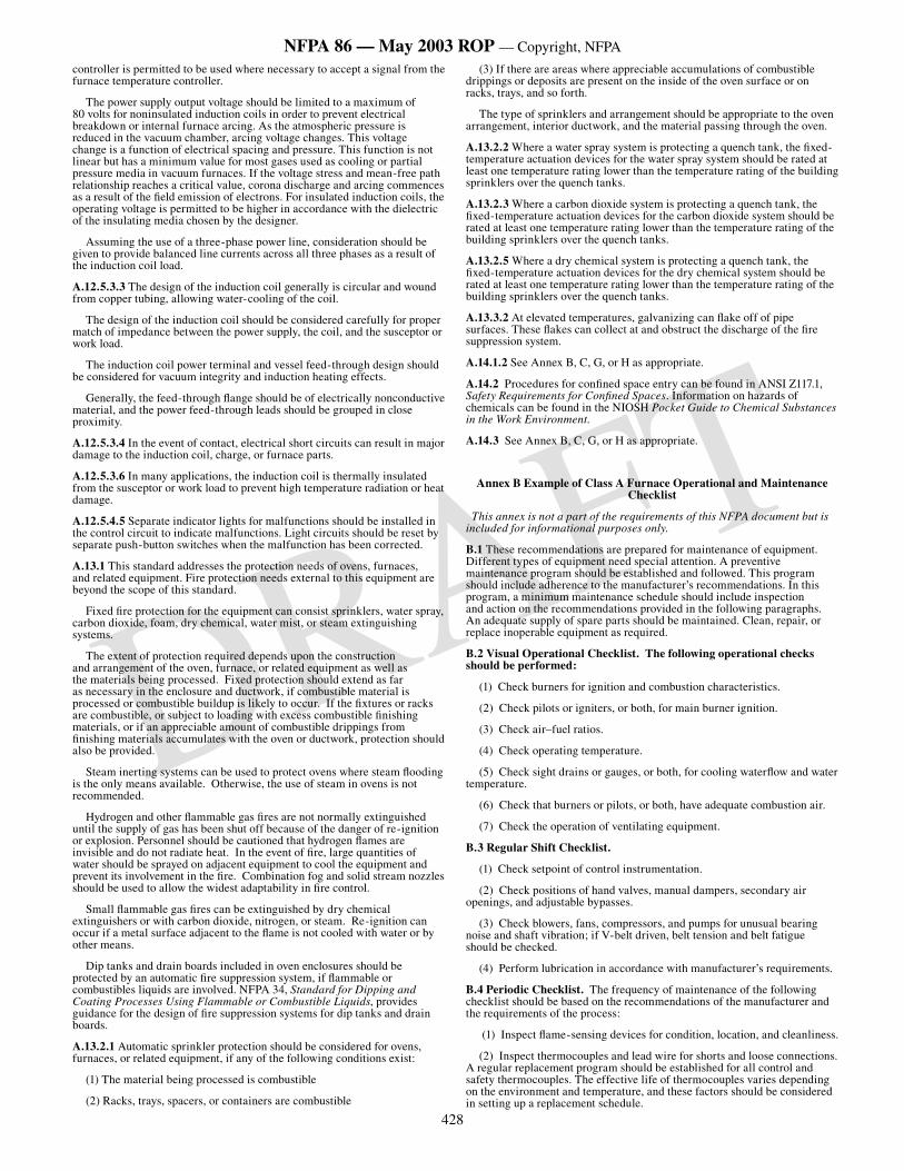
428
NFPA 86 — May 2003 ROP — Copyright, NFPA
DRAFT
controller is permitted to be used where necessary to accept a signal from the furnace temperature controller.
The power supply output voltage should be limited to a maximum of 80 volts for noninsulated induction coils in order to prevent electrical breakdown or internal furnace arcing. As the atmospheric pressure is reduced in the vacuum chamber, arcing voltage changes. This voltage change is a function of electrical spacing and pressure. This function is not linear but has a minimum value for most gases used as cooling or partial pressure media in vacuum furnaces. If the voltage stress and mean-free path relationship reaches a critical value, corona discharge and arcing commences as a result of the field emission of electrons. For insulated induction coils, the operating voltage is permitted to be higher in accordance with the dielectric of the insulating media chosen by the designer.
Assuming the use of a three-phase power line, consideration should be given to provide balanced line currents across all three phases as a result of the induction coil load.
A.12.5.3.3 The design of the induction coil generally is circular and wound from copper tubing, allowing water-cooling of the coil.
The design of the induction coil should be considered carefully for proper match of impedance between the power supply, the coil, and the susceptor or work load.
The induction coil power terminal and vessel feed-through design should be considered for vacuum integrity and induction heating effects.
Generally, the feed-through flange should be of electrically nonconductive material, and the power feed-through leads should be grouped in close proximity.
A.12.5.3.4 In the event of contact, electrical short circuits can result in major damage to the induction coil, charge, or furnace parts.
A.12.5.3.6 In many applications, the induction coil is thermally insulated from the susceptor or work load to prevent high temperature radiation or heat damage.
A.12.5.4.5 Separate indicator lights for malfunctions should be installed in the control circuit to indicate malfunctions. Light circuits should be reset by separate push-button switches when the malfunction has been corrected.
A.13.1 This standard addresses the protection needs of ovens, furnaces, and related equipment. Fire protection needs external to this equipment are beyond the scope of this standard.
Fixed fire protection for the equipment can consist sprinklers, water spray, carbon dioxide, foam, dry chemical, water mist, or steam extinguishing systems.
The extent of protection required depends upon the construction and arrangement of the oven, furnace, or related equipment as well as the materials being processed. Fixed protection should extend as far as necessary in the enclosure and ductwork, if combustible material is processed or combustible buildup is likely to occur. If the fixtures or racks are combustible, or subject to loading with excess combustible finishing materials, or if an appreciable amount of combustible drippings from finishing materials accumulates with the oven or ductwork, protection should also be provided.
Steam inerting systems can be used to protect ovens where steam flooding is the only means available. Otherwise, the use of steam in ovens is not recommended.
Hydrogen and other flammable gas fires are not normally extinguished until the supply of gas has been shut off because of the danger of re-ignition or explosion. Personnel should be cautioned that hydrogen flames are invisible and do not radiate heat. In the event of fire, large quantities of water should be sprayed on adjacent equipment to cool the equipment and prevent its involvement in the fire. Combination fog and solid stream nozzles should be used to allow the widest adaptability in fire control.
Small flammable gas fires can be extinguished by dry chemical extinguishers or with carbon dioxide, nitrogen, or steam. Re-ignition can occur if a metal surface adjacent to the flame is not cooled with water or by other means.
Dip tanks and drain boards included in oven enclosures should be protected by an automatic fire suppression system, if flammable or combustibles liquids are involved. NFPA 34, Standard for Dipping and Coating Processes Using Flammable or Combustible Liquids, provides guidance for the design of fire suppression systems for dip tanks and drain boards.
A.13.2.1 Automatic sprinkler protection should be considered for ovens, furnaces, or related equipment, if any of the following conditions exist:
(1) The material being processed is combustible
(2) Racks, trays, spacers, or containers are combustible
(3) If there are areas where appreciable accumulations of combustible drippings or deposits are present on the inside of the oven surface or on racks, trays, and so forth.
The type of sprinklers and arrangement should be appropriate to the oven arrangement, interior ductwork, and the material passing through the oven.
A.13.2.2 Where a water spray system is protecting a quench tank, the fixed-temperature actuation devices for the water spray system should be rated at least one temperature rating lower than the temperature rating of the building sprinklers over the quench tanks.
A.13.2.3 Where a carbon dioxide system is protecting a quench tank, the fixed-temperature actuation devices for the carbon dioxide system should be rated at least one temperature rating lower than the temperature rating of the building sprinklers over the quench tanks.
A.13.2.5 Where a dry chemical system is protecting a quench tank, the fixed-temperature actuation devices for the dry chemical system should be rated at least one temperature rating lower than the temperature rating of the building sprinklers over the quench tanks.
A.13.3.2 At elevated temperatures, galvanizing can flake off of pipe surfaces. These flakes can collect at and obstruct the discharge of the fire suppression system.
A.14.1.2 See Annex B, C, G, or H as appropriate.
A.14.2 Procedures for confined space entry can be found in ANSI Z117.1, Safety Requirements for Confined Spaces. Information on hazards of chemicals can be found in the NIOSH Pocket Guide to Chemical Substances in the Work Environment.
A.14.3 See Annex B, C, G, or H as appropriate.
Annex B Example of Class A Furnace Operational and Maintenance Checklist
This annex is not a part of the requirements of this NFPA document but is included for informational purposes only.
B.1 These recommendations are prepared for maintenance of equipment. Different types of equipment need special attention. A preventive maintenance program should be established and followed. This program should include adherence to the manufacturer’s recommendations. In this program, a minimum maintenance schedule should include inspection and action on the recommendations provided in the following paragraphs. An adequate supply of spare parts should be maintained. Clean, repair, or replace inoperable equipment as required.
B.2 Visual Operational Checklist. The following operational checks should be performed:
(1) Check burners for ignition and combustion characteristics.
(2) Check pilots or igniters, or both, for main burner ignition.
(3) Check air–fuel ratios.
(4) Check operating temperature.
(5) Check sight drains or gauges, or both, for cooling waterflow and water temperature.
(6) Check that burners or pilots, or both, have adequate combustion air.
(7) Check the operation of ventilating equipment.
B.3 Regular Shift Checklist.
(1) Check setpoint of control instrumentation.
(2) Check positions of hand valves, manual dampers, secondary air openings, and adjustable bypasses.
(3) Check blowers, fans, compressors, and pumps for unusual bearing noise and shaft vibration; if V-belt driven, belt tension and belt fatigue should be checked.
(4) Perform lubrication in accordance with manufacturer’s requirements.
B.4 Periodic Checklist. The frequency of maintenance of the following checklist should be based on the recommendations of the manufacturer and the requirements of the process:
(1) Inspect flame-sensing devices for condition, location, and cleanliness.
(2) Inspect thermocouples and lead wire for shorts and loose connections. A regular replacement program should be established for all control and safety thermocouples. The effective life of thermocouples varies depending on the environment and temperature, and these factors should be considered in setting up a replacement schedule.
429
NFPA 86 — May 2003 ROP — Copyright, NFPA
DRAFT
(3) Check setting and operation of low and high temperature limit devices.
(4) Test visual or audible alarm systems, or both, for proper signals.
(5) Check igniters and verify proper gap.
(6) Check all pressure switches for proper pressure settings.
(7) Check control valves, dampers, and actuators for free, smooth action and adjustment.
(8) Test the interlock sequence of all safety equipment. If possible, the interlocks should be made to fail manually, verifying that the related equipment operates as specified by the manufacturer.
(9) Test the safety shut-off valves for operation and tightness of closure as specified by the manufacturer.
(10) Test the main fuel manual valves for operation and tightness of closure as specified by the manufacturer.
(11) Test the pressure switches for proper operation at setpoint.
(12) Visually inspect electrical switches, contacts, or controls for signs of arcing or contamination.
(13) Test instruments for proper response to thermocouple failure.
(14) Clean or replace the air blower filters.
(15) Clean the water, fuel, gas compressor, and pump strainers.
(16) Clean the fire-check screens and valve seats, and test for freedom of valve movement.
(17) Inspect burners and pilots for proper operation, air–fuel ratio, plugging, or deterioration. Burner refractory parts should be examined to ensure good condition.
(18) Check all orifice plates, air–gas mixers, flow indicators, meters, gauges, and pressure indicators; if necessary, clean or repair them.
(19) Check the ignition cables and transformers.
(20) Check the operation of modulating controls.
(21) Check the integrity of and the interior of the equipment, ductwork, and ventilation systems for cleanliness and flow restrictions.
(22) Test pressure-relief valves; if necessary, repair or replace.
(23) Inspect air, water, fuel, and impulse piping for leaks.
(24) Inspect radiant tubes and heat exchanger tubes for leakage and repair if necessary.
(25) Lubricate the instrumentation, valve motors, valves, blowers, compressors, pumps, and other components.
(26) Test and recalibrate instrumentation in accordance with manufacturer’s recommendations.
(27) Test flame safeguard units. A complete shutdown and restart should be made to check the components for proper operation.
(28) Check electric heating elements for contamination, distortion, cracked or broken refractory element supports, and proper position. Repair or replace if grounding or shorting can occur.
(29) Check electric heating element terminals for tightness.
Annex C Example of Class B Furnace Operational and Maintenance Checklist
This annex is not a part of the requirements of this NFPA document but is included for informational purposes only.
C.1 These recommendations are prepared for maintenance of equipment. Different types of equipment need special attention. A preventive maintenance program should be established and followed. This program should include adherence to the manufacturer’s recommendations. In this program, a minimum maintenance schedule should include inspection and action on the recommendations provided in the following paragraphs. An adequate supply of spare parts should be maintained. Clean, repair, or replace inoperable equipment as required.
C.2 Visual Operational Checklist.
(1) Check burners for ignition and combustion characteristics.
(2) Check pilots or igniters, or both, for main burner ignition.
(3) Check air–fuel ratios.
(4) Check operating temperatures.
(5) Check sight drains or gauges, or both, for cooling water flow and water temperature.
(6) Check that burners or pilots, or both, have adequate combustion air.
(7) Check the operation of ventilating equipment.
C.3 Regular Shift Checklist.
(1) Check setpoint of control instrumentation.
(2) Check positions of hand valves, manual dampers, secondary air openings, and adjustable bypasses.
(3) Check blowers, fans, compressors, and pumps for unusual bearing noise and shaft vibration; if V-belt driven, belt tension and belt fatigue should be checked.
(4) Perform lubrication in accordance with manufacturer’s requirements.
C.4 Periodic Checklist. The frequency of maintenance of the following checklist should be based on the recommendations of the manufacturer and the requirements of the process:
(1) Inspect flame-sensing devices for condition, location, and cleanliness.
(2) Inspect thermocouples and lead wire for shorts and loose connections. A regular replacement program should be established for all control and safety thermocouples. The effective life of thermocouples varies depending on the environment and temperature, and these factors should be considered in setting up a replacement schedule.
(3) Check setting and operation of low and high temperature limit devices.
(4) Test visual or audible alarm systems, or both, for proper signals.
(5) Check igniters and verify proper gap.
(6) Check all pressure switches for proper pressure settings.
(7) Check control valves, dampers, and actuators for free, smooth action and adjustment.
(8) Test the interlock sequence of all safety equipment. If possible, the interlocks should be made to fail manually, verifying that the related equipment operates as specified by the manufacturer.
(9) Test the safety shut-off valves for operation and tightness of closure as specified by the manufacturer.
(10) Test the main fuel manual valves for operation and tightness of closure as specified by the manufacturer.
(11) Test the pressure switches for proper operation at setpoint.
(12) Visually inspect electrical switches, contacts, or controls for signs of arcing or contamination.
(13) Test instruments for proper response to thermocouple failure.
(14) Clean or replace the air blower filters.
(15) Clean the water, fuel, gas compressor, and pump strainers.
(16) Clean the fire-check screens and valve seats and test for freedom of valve movement.
(17) Inspect burners and pilots for proper operation, air–fuel ratio, plugging, or deterioration. Burner refractory parts should be examined to ensure good condition.
(18) Check all orifice plates, air–gas mixers, flow indicators, meters, gauges, and pressure indicators; if necessary, clean or repair them.
(19) Check the ignition cables and transformers.
(20) Check the operation of modulating controls.
(21) Check the integrity of and the interior of the equipment, ductwork, and ventilation systems for cleanliness and flow restrictions.
(22) Test pressure-relief valves; if necessary, repair or replace.
(23) Inspect air, water, fuel, and impulse piping for leaks.
(24) Inspect radiant tubes and heat exchanger tubes for leakage and repair if necessary.
(25) Lubricate the instrumentation, valve motors, valves, blowers, compressors, pumps, and other components.
430
NFPA 86 — May 2003 ROP — Copyright, NFPA
DRAFT
(26) Test and recalibrate instrumentation in accordance with manufacturer’s recommendations.
(27) Test flame safeguard units. A complete shutdown and restart should be made to check the components for proper operation.
(28) Check electric heating elements for contamination, distortion, cracked or broken refractory element supports, and proper position. Repair or replace if grounding or shorting can occur.
(29) Check electric heating element terminals for tightness.
Annex D The Lower Limit of Flammability and the Autogenous Ignition Temperature of Certain Common Solvent Vapors Encountered in Ovens
This annex is not a part of the requirements of this NFPA document but is included for informational purposes only.
D.1 The following is an abstract of Underwriters Laboratories Inc. Bulletin of Research No. 43.
This Bulletin of Research reports an investigation conducted by Underwriters Laboratories Inc. to determine the lower limit of flammability (upward propagation) and the autogenous ignition temperature of certain common solvent vapors encountered in industrial ovens. The solvents included acetone, iso-amyl acetate, benzene, normal butyl alcohol, cyclohexane, cyclohexanone, metapara creosol, ethyl alcohol, ethyl lacate, gasoline, normal hexane, high solvency petroleum naphtha, methyl alcohol, methyl ethyl ketone, methyl lactate, No. 10 Mineral Spirits, toluene, turpentine, and VM and P naphtha.
The lower limits of flammability of the solvent vapors in air at initial temperatures encountered in the operation of ovens were determined in a specially designed, electrically heated, closed explosion vessel of steel having a capacity of 1 ft3 (0.028 m3) [15 1/
4 in. (387 mm) high, 12 in. (305
mm) internal diameter]. It was equipped with an observation window, an externally driven mixing fan, and inlet and outlet valves. A transformer rated 15,000 V, 60 mA, 60 cycles for the secondary and having a 0.009 mfd condenser connected across the secondary was used to produce an electric discharge for ignition.
The lower limits of flammability of all solvents included in this investigation were found to be lowered on increasing the initial ambient temperature, these changes in the lower limits being of such magnitude that they cannot be safely neglected in practical calculations of the amount of ventilation required to prevent formation of hazardous concentrations of the vapors of the solvents in industrial ovens. The magnitude of the change in the lower limit with a given increase in initial temperature varied with the different solvents.
The autogenous ignition temperature (in air) of the solvent vapors was determined in combustion chambers of iron, stainless steel (AISI Type No. 302), copper, zinc, and yellow brass, representing metals commonly used in oven construction. Determinations in glass and quartz chambers were included for comparison. The autogenous ignition temperature of the solvents is influenced to some extent by catalytic or other reactions of the solvent vapor–air mixtures with the heated metals or their oxides. Whether the ignition temperature of the solvent is increased or decreased (as compared with values obtained with glass or quartz combustion chambers) depends on the particular combinations of solvent vapor and metals.
The ignition temperatures of solvents in metal chambers were higher, for the most part, than the ignition temperatures of the same solvents in glass or quartz chambers, but exceptions were found where the values obtained in the metal chambers were lower (i.e., butyl alcohol in copper and brass chambers). The autogenous ignition temperature of many solvents included in the investigation is within the range of temperatures encountered in industrial ovens and, if conditions are such as to allow formation of flammable vapor–air mixtures in the oven, autogenous ignition can occur.
NOTE: In calculating ventilation requirements for batch ovens operating from 250°F to 500°F (121°C to 260°C), values for the lower flammable limit of the solvent determined at the operating temperature of the oven should be used where such data are available. However, where the data are obtainable only for room temperature, a correction factor is required. An averaged factor of 1.4 has been obtained from a graph of the experimental data plotted for a number of selected solvents over temperature ranges of 70° to 250°F (21° to 121°C) (1.25) and 250° to 500°F (121° to 260°C) (1.56).
Annex E Continuous Solvent Vapor Concentration Indicator and Controller
This annex is not a part of the requirements of this NFPA document but is included for informational purposes only.
E.1 Solvent Vapor Analyzer Systems. A solvent vapor concentration indicator is a measurement system used to determine the solvent vapor concentration in a Class A oven, expressed as percent of the lower explosive limit (LEL), also called the lower flammable limit (LFL). It is required for safe operation of ovens at solvent concentrations above 25 percent LEL. The measurement system consists of three integral parts:
(1) The gas sample system that delivers the oven atmosphere sample to the analyzer
(2) The solvent vapor concentration analyzer
(3) The safety logic system that is activated by the analyzer
The oven atmosphere should be sampled at a point that best represents the average concentration of solvent vapor in the oven or oven zone. This usually is at the oven exhaust point. Care should be taken to provide sufficient turbulence within the oven to avoid significant pockets of high solvent concentration. The sample system consists of a sample pickup tube, sample line, sample pump, and filter or other sample conditioning devices. The volume of the sample system should be as small as possible and the sample flow rate maximized for fast response of the system. Special precautions, such as heating the sample lines and analyzer to prevent condensation of volatiles in the sample system, might be required. The length of the sample line should be minimized by locating the analyzer close to the sample point.
The solvent vapor concentration analyzer can be one of several types. The choice of the appropriate type depends on factors such as the solvent composition, the need for calibration of more than one solvent, the necessary response time of the measurement system, and the ability to handle factors such as contaminants and oxygen content. The types of analyzers used are described as follows:
(1) Catalytic Combustion. Combustion of solvent vapor occurs on a heated catalyst surface, such as a platinum wire. The heat of combustion causes a change in electrical resistance, which is calibrated in terms of percent LEL. Because the measurement is based on combustion, the calibration does vary significantly for different solvents. However, contamination of the catalyst with silicones can cause a calibration shift.
(2) Infrared. The sample is passed through a measurement cell where infrared energy is absorbed by the solvent vapor and compared with the energy absorbed in a reference cell containing background gas. Contamination by silicone is not a problem with this type of analyzer, but the calibration is specific to certain classes of solvents and can vary considerably for various solvent types. Its area of application is for single solvent systems where silicone poisoning might be a problem.
(3) Flame Temperature. This is a combustion-type analyzer in which solvent vapor in the sample is burned as it passes through a chamber containing a small, constantly burning flame. A temperature sensor is located immediately above the flame. The temperature varies with the amount of solvent burned in the flame and is calibrated in percent LEL. Contamination by silicones is not a problem, and calibration is relatively constant for various solvents.
(4) Flame Ionization. Ionization of solvent vapor in contact with a hydrogen flame causes a change in electrical properties that can be measured and calibrated in percent LEL. This method also is used to measure very low concentrations of solvent vapor. Very rapid response can be obtained, but the calibration can vary for some types of solvents.
All of the various types of analyzers are to be routinely calibrated using zero and span gas. Standards require initial calibration for the specific solvents being measured.
The safety logic system involves high-limit contacts in the analyzer or recorder, or both, that stop the conveyor or other means of solvent introduction and actuate dampers or fan motor drives to provide maximum makeup air and exhaust. Other parts of the analyzer logic system include flow meters and pressure switches to verify the proper operation of the sample system. The solvent vapor concentration analyzer also can be utilized to control the percent LEL in the oven by modulation of the makeup air or exhaust.
It cannot be emphasized too strongly that the solvent vapor concentration measurement system is to have a very fast response time so that corrective action can be taken in response to upsets such as excessive introduction of solvent into the oven. A response time of as little as 5 seconds might be required in some cases.
431
NFPA 86 — May 2003 ROP — Copyright, NFPA
DRAFT
E.2 LEL Values and Calibration Concerns. Proper operation of a continuous solvent vapor concentration analyzer requires careful calibration for the correct LEL values of the particular solvent or solvent mixtures and for response of the analyzer to the particular solvents.
E.2.1 LEL Values and Temperature Corrections. LEL values for many commonly used solvents are given in Table 9.2.6.2.2(a) and Table 9.2.6.2.2(b). Additional data can be found in NFPA 325, Guide to Fire Hazard Properties of Flammable Liquids, Gases, and Volatile Solids.
Note: Although NFPA 325 has been officially withdrawn from the National Fire Codes, the information is still available in NFPA’s Fire Protection Guide to Hazardous Materials.
For mixtures of solvents, the LEL of the mixture is calculated by the following formula:
Where:
P1,2 . . . n = % by volume of component 1,2. . .n
L1,2 . . . n = LEL value of each solvent
E.2.2 Instrument Calibration Factors. The solvent vapor analyzer systems described in Section D.1 respond differently to various solvent vapors. Instrument calibration to the specific solvent vapor or solvent mixture vapor is required both before initial operation of the instrument and on some routine schedule after initial operation.
E.2.2.1 Initial Calibration. The instrument should be calibrated initially with the solvent vapor or solvent mixture vapor used in the oven application. A label describing this calibration should be affixed to the instrument. A permanent record of this calibration should be included with records for the instrument.
The user should understand how the instrument responds to vapors for which the instrument is not calibrated, including other solvent vapors or mixtures of solvent vapors present in the sample and vapors whose relative response data is not known. The instrument manufacturer should be consulted for guidance in such cases.
The initial calibration should be based on worst case considerations, including the following:
(1) If a variety or mixture of solvent vapors is to be present, the instrument should be calibrated for the solvent vapor that produces the lowest instrument signal. All other solvent vapors should indicate a meter value greater than the actual concentration, so that any error in reading is always in a safe, or early warning, direction.
(2) Solvent mixtures containing minor components can be calibrated without the minor components where the estimated error produced is less than 3 percent of the meter reading.
(3) When calculating the LEL value and oven temperature correction as provided in Table 9.2.5.2, the maximum oven temperature should be used.
E.2.2.2 Field Calibration. Solvent vapor analyzer systems require field calibration checks during normal operation to verify the accuracy of the system. The manufacturer should supply the user with a recommended schedule for calibration checks. This schedule should be contained in the operating instructions for the specific instrument used.
It is recommended that field calibrations be made using a known concentration of the actual solvent vapor present in the process.
Field calibration also can be performed using a known concentration of reference test gas in situations where use of the actual solvent vapor present is not possible. This reference test gas could be used as a substitute for the actual solvent vapor, and meter reading adjustments can be made based on test gas response data supplied by the instrument manufacturer.
The use of relative response data in making field calibration checks is not recommended.
Certain materials, including but not limited to silicones, sulfur compounds, phosphorus compounds, chlorinated compounds, and halogenated hydrocarbons, have a poisoning or inhibiting effect on some solvent vapor analyzers. These materials can produce a loss in sensitivity in certain instruments. If the presence of desensitizing materials in the sample is known or suspect, instrument field calibration checks should be performed on a more frequent basis. The instrument manufacturer should be consulted for guidance on calibration frequency in these situations.
Annex F Steam Extinguishing Systems
This annex is not a part of the requirements of this NFPA document but is included for informational purposes only.
F.1 General. Steam extinguishes fire by the exclusion of air or the reduction of the oxygen content of the atmosphere in a manner similar to carbon dioxide or other inert gases. The use of steam precedes other modern
smothering systems. Steam is not a practical extinguishing agent except where a large steam supply is continuously available. The possible burn hazard should be considered in any steam extinguishing installation. A visible cloud of condensed vapor, popularly described as steam, is incapable of extinguishment.
While many fires have been extinguished by steam, its use often has been unsuccessful due to lack of understanding of its limitations. Except for specialized applications, other types of smothering systems are preferred in modern practice. No complete standard covering steam smothering systems has been developed.
One pound of saturated steam at 212°F (100°C) and normal atmospheric pressure has a volume of 26.75 ft3 (0.76 m3). A larger percentage of steam is required to prevent combustion than in the case of other inert gases used for fire extinguishment. Fires in substances that form glowing coals are difficult to extinguish with steam, owing to the lack of cooling effect. There are some types of fire for which steam is completely ineffective, such as fires involving ammonium nitrate and similar oxidizing materials.
Steam smothering systems should be permitted only where oven temperatures exceed 225°F (107°C) and where large supplies of steam are available at all times while the oven is in operation. Complete standards paralleling those for other extinguishing agents have not been developed for the use of steam as an extinguishing agent, and, until this is done, the use of this form of protection is not as dependable, nor are the results as certain, as those provided by water, carbon dioxide, dry chemical, or foam.
Release devices for steam smothering systems should be manual, and controls should be arranged to close down oven outlets to the extent practicable.
F.2 Life Hazard.
(1) Equipment should be arranged to prevent operating of steam valves when doors of box-type ovens or access doors or panels of conveyor ovens are open.
(2) A separate outside steam manual shut-off valve should be provided for closing off the steam supply during oven cleaning. The valve should be locked closed whenever employees are in the oven.
(3) The main valve should be designed to open slowly, as the release should first open a small bypass in order to allow time for employees in the vicinity to escape and also to protect the piping from severe water hammer. A steam trap should be connected to the steam supply near the main valve to keep this line free of condensate.
F.3 Steam Outlets. If steam is used, then steam outlets should be sufficiently large to supply 8 lb/min (3.6 kg/min) of steam for each 100 ft3 (2.8 m3) of oven volume. They preferably should be located near the bottom of the oven but might be located near the top, pointing downward, if the oven is not over 20 ft (6.1 m) high. Steam jets should be directed at dip tanks (in a manner to avoid disturbing the liquid surface) or other areas of special hazard.
Annex G Example of Class C Furnace Operational and Maintenance Checklist
This annex is not a part of the requirements of this NFPA document but is included for informational purposes only.
G.1 Visual Operational Checklist. The following operational checks should be performed:
(1) Check burners for ignition and combustion characteristics.
(2) Check pilots or igniters, or both, for main burner ignition.
(3) Check air–fuel ratios.
(4) Check operating temperatures.
(5) Check sight drains or gauges, or both, for cooling waterflow and water temperature.
(6) Check that burners or pilots, or both, have adequate combustion air.
(7) Check the operation of ventilating equipment.
G.2 Regular Shift Checklist. The following regular shift checks should be performed:
(1) Take the necessary gas analyses; if automatic gas analyzers are used, the manual and automatic readings should coincide. Recalibrate automatic gas analyzers.
(2) Check setpoint of control instrumentation.
(3) Check positions of hand valves, manual dampers, secondary air openings, and adjustable bypasses.
432
NFPA 86 — May 2003 ROP — Copyright, NFPA
DRAFT
(4) Check blowers, fans, compressors, and pumps for unusual bearing noise and shaft vibration; if V-belt driven, belt tension and belt fatigue should be checked.
(5) Perform lubrication in accordance with manufacturer’s requirements.
G.3 Weekly Checklist. The following weekly checks should be performed:
(1) Inspect flame-sensing devices for condition, location, and cleanliness.
(2) Inspect thermocouples and lead wire for shorts and loose connections.
(3) Check setting and operation of low and high temperature limit devices.
(4) Test visual or audible alarm systems, or both, for proper signals.
(5) Check igniters and verify proper gap.
(6) Check all pressure switches for proper pressure settings.
(7) Check control valves, dampers, and actuators for free, smooth action and adjustment.
G.4 Periodic Checklist. The frequency of maintenance of the following should be based on the recommendations of the manufacturer and the requirements of the process:
(1) Test the interlock sequence of all safety equipment. If possible, the interlocks should be made to fail manually verifying that the related equipment operates as specified by the manufacturer.
(2) Test the safety shut-off valves for tightness of closure as specified by the manufacturer.
(3) Test the main fuel manual valves for operation.
(4) Test the pressure switches for proper operation.
(5) Visually inspect electrical switches, contacts, or controls for signs of arcing or contamination.
(6) Test instruments for proper response to thermocouple failure.
(7) Verify the results of a timed purge procedure, if used.
(8) Clean the air blower filters.
(9) Clean the water, gas compressor, and pump strainers.
(10) Clean the fire-check screens and valve seats and test for freedom of valve movement.
(11) Inspect burners and pilots; if necessary, clean them.
(12) Check orifice plates, air–gas mixers, flow indicators, meters, gauges, and pressure indicators; if necessary, clean or repair them.
(13) Check the ignition cables and transformers.
(14) Check the operation of modulating controls.
(15) Check the interior of the equipment, ductwork, and ventilation systems for cleanliness and flow restrictions.
(16) Test pressure-relief valves; if necessary, clean or replace.
(17) Inspect air, water, fuel, and impulse piping for leaks.
(18) Inspect radiant tubes and heat exchanger tubes for leakage and repair if necessary.
(19) Lubricate the instrumentation, valve motors, valves, blowers, compressors, pumps, and other components.
(20) Test instrumentation in accordance with manufacturer’s recommendations.
(21) Test flame safeguard units.
G.5 Maintenance of Gas Equipment.
G.5.1 General. These recommendations are prepared for maintenance of gas equipment. Special types of equipment need special attention. A preventive maintenance program should be established and followed. This program should include adherence to the manufacturer’s recommendations. In this program, a minimum maintenance schedule should include inspection and action on the recommendations provided in G.5.2 through G.5.5. An adequate supply of spare parts should be maintained.
G.5.2 Burners and Pilots. Burners and pilots should be kept clean and in proper operating condition. Burner refractory parts should be examined at frequent regular intervals to ensure good condition.
G.5.3 Flame Safeguard Equipment. Where automatic flame safeguards are used, a complete shutdown and restart should be made at frequent intervals to check the components for proper operation.
G.5.4 Other Safeguard Equipment. Accessory safeguard equipment, such as manual reset valves, automatic safety shut-off valves, pressure or vacuum switches, high temperature limit switches, draft control, manual shut-off valves, airflow switches, door switches, and gas valves, should be operated at frequent, regular intervals to ensure proper functioning. If inoperative, they should be repaired or replaced promptly.
Where fire checks are installed in air–gas mixture piping, the pressure loss across the fire checks should be measured at regular intervals. Where excessive pressure loss is found, screens should be removed and cleaned. Water-type backfire checks should be inspected at frequent intervals, and the liquid level should be maintained.
G.5.5 Safety Shut-off Valves.
All safety shut-off valves should be checked for leakage and proper operation at frequent, regular intervals. An example procedure for testing gas safety shut-off valves is outlined in A.7.7.2.3.
G.6 Maintenance of Electric Furnaces and Equipment.
G.6.1 General. A program of regular inspection and maintenance of electric furnaces is essential to the safe operation of that equipment. Manufacturer’s recommendations should be followed rigorously, resulting in a long, trouble-free furnace life. Suitable spare parts should be stocked to ensure quick replacement as needed.
G.6.2 Heating Elements. The heating elements should be inspected at regular intervals and any foreign contamination removed. Repair is essential if elements are dislodged or distorted, causing them to touch alloy hearths or furnace components so that grounding or shorting can occur. Element terminals should be checked periodically and tightened, since loose connections cause arcing and oxidation that can result in burnout of the terminal.
G.6.3 Insulation and Refractory Materials. Furnace linings need attention where protective atmospheres are used to make certain that excessive carbon has not been deposited. Grounding or shorting of the elements can occur unless recommended burn-out procedures are followed. Cracked or broken refractory element supports should be replaced as necessary.
G.6.4 Thermocouples. A regular replacement program should be established for all control and safety thermocouples. The effective life of thermocouples varies depending on the environment and temperature, and these factors should be considered in setting up a replacement schedule.
G.6.5 Auxiliary and Control Devices. Contactors should be checked and replaced periodically where pitting due to arcing could result in welding of the contacts and uncontrolled application of power to the furnace. All control components, including pyrometers and relays, should be checked periodically to ensure proper operation or control accuracy. Instructions provided by the manufacturer of each control component should be followed with care.
G.6.6 Voltage. The voltage supplied to electric furnaces should be maintained within reasonable limits to ensure against overloading of control devices and transformers. Undervoltage can result in operational failure of relays and solenoid valves.
G.6.7 Water Cooling. If components are water-cooled, it is important to check the flow and temperature of the cooling water frequently.
G.6.8 Interlocks. Periodic checks of all safety interlocks are essential. High-frequency generators should have functioning door interlocks to prevent operators from entering the enclosure while any power is on. These safety devices should be checked frequently.
Annex H Maintenance Checklist
This annex is not a part of the requirements of this NFPA document but is included for informational purposes only.
H.1 General. A program of regular inspection and maintenance of the vacuum furnace is essential to the safe operation of the equipment and should be instituted and followed rigorously. Basic heating devices, such as heating elements or induction coils, should be designed for ease of maintenance. If special tools are needed, they should be supplied by the furnace manufacturer.
H.1 Vacuum System. Mechanical vacuum pumps should be checked and repaired as necessary. The following is a partial list:
(1) Drive belts are not worn.
(2) Drive belt tension is proper.
(3) No oil leaks are at the shaft seals.
433
NFPA 86 — May 2003 ROP — Copyright, NFPA
DRAFT
(4) Oil level is correct.
(5) Oil is free of dirt and water accumulation.
(6) Drip legs are drained.
(7) Mounting bolts are tight.
(8) Vacuum lines and vibration couplings are tight.
The high vacuum diffusion pump should be checked and repaired as necessary. The following is a partial list:
(1) Waterflow for cooling is correct.
(2) Heating elements are tight and indicate proper electrical parameters.
(3) Oil level is correct.
(4) Oil is not contaminated.
Control vacuum valves should be checked and repaired. The following is a partial list:
(1) Air supply filter is drained and operating.
(2) Air supply oiler is filled to correct level and operating.
(3) Pilot valves are not leaking excess air.
(4) Moving O-ring seals are cleaned or changed where excess wear is indicated.
Numerous stationary and moving vacuum seals, O-rings, and other rubber gaskets are associated with the main vacuum vessel. These seals should be inspected properly to ensure cleanliness, freedom from cracks or gouges, and retention of elasticity. The main front and rear door, or bottom head, where work regularly passes, should receive particular attention.
H.1.2 Hot Zone (Resistance Heaters) — Power Supply. The power supply should be inspected and corrected as required. The following is a partial list:
(1) Primary and secondary wiring and cables are tight and free from overheating.
(2) Proper ventilation and air cooling or proper waterflow per unit or transformer is present.
(3) Control relays or contactors are free of contact pitting or arcing, which could result in contact welding.
(4) Power supply voltage is maintained within reasonable limits to ensure against overloading.
Note: Undervoltage can result in operational failure of any one of the numerous vacuum furnace systems.
H.1.3 Hot Zone (Resistance Heaters) — Thermocouples. A regular replacement program should be established for all control and safety thermocouples.
It should be noted that the effective life of thermocouples varies depending on the environment and process, the temperature, and the vacuum, and these factors should be considered in setting up a replacement program.
H.1.4 Hot Zone (Resistance Heaters) — Instrumentation Temperature and vacuum instrumentation should be set up on a regular calibration and test schedule.
Many components of the vacuum furnace are required to be water-cooled. Drain lines should be inspected for proper flow and temperature of the cooling water. Pressure regulators, strainers, and safety vents should be inspected for proper setting and maintained free from dirt and contamination.
If an evaporative cooling tower is integral to the furnace system, the tower should be cleaned, the motor and bearings greased, and the water strainer cleaned on a regular basis.
H.1.5 Hot Zone (Resistance Heaters) — Interlocks and Alarms. Periodic checks of all safety interlocks and alarms should be performed. Particular attention should be given to overtemperature safety devices, low air pressure, insufficient cooling water, and vacuum, oil temperature, and low oil alarms.
(1) The following continuous observations should be made:
(a) Review auxiliary vacuum instrumentation for proper indication of system performance (i.e., foreline, holding pump, mechanical pump, and diffusion pump operating temperature).
(b) Review power instrumentation and trim or zone control settings.
(c) Check instrumentation for “on conditions,” chart paper, and active operation.
(d) Check oil level in mechanical pumps and diffusion pump.
(e) Check mechanical vacuum pump, blowers, gas fans, and oil pumps for unusual noise or vibration. Review V-belt drive, belt tension, and belt fatigue.
(f) Check quench gas pressure and available capacity.
(g) Check for proper operation of ventilation equipment if required for the particular installation.
(2) The following regular shift observations should be made:
(a) Review auxiliary vacuum instrumentation for proper indication of system performance (i.e., foreline, holding pump, mechanical pump, and diffusion pump operating temperature).
(b) Review power instrumentation and trim or zone control settings.
(c) Check instrumentation for “on conditions,” chart paper, and active operation.
(d) Check oil level in mechanical pumps and diffusion pump.
(e) Check mechanical vacuum pump, blowers, gas fans, and oil pumps for unusual noise or vibration. Review V-belt drive, belt tension, and belt fatigue.
(f) Check quench gas pressure and available capacity.
(3) The following weekly checks should be made:
(a) Review hot zone for normal condition of heating elements, heat shields or retainers, insulators, and work support or mechanism.
(b) Test thermocouples and lead wires for broken insulators, shorts, and loose connections.
(c) Test visible or audible alarms for proper signals.
(4) The following monthly observations should be made:
(a) Test interlock sequence of all safety equipment. Make each interlock fail manually, verifying that related equipment shuts down or stops as required.
(b) Inspect all electrical switches and contacts, and repair as required.
(c) Test all temperature instrument fail-safe devices, making certain that the control instrument or recorder drives in the proper direction.
(d) Clean all water, gas compressor, and pump strainers.
(e) Test automatic or manual turndown equipment.
(f) Change mechanical pump oil and diffusion pump oil, if necessary.
(g) Test pressure-relief valves, and clean if necessary.
(h) Inspect air, inert gas, water, and hydraulic lines for leaks.
(5) The following periodic maintenance checks and procedures should be made. The frequency of these checks and procedures depends on the equipment manufacturer’s recommendations:
(a) Inspect vacuum chamber O-ring and other gaskets for proper sealing.
(b) Review the vacuum chamber vessel for evidence of hot spots that indicate improper water cooling.
(c) Review furnace internals in detail for heating element, heat shield, and work support or mechanism failure or deterioration.
(d) Lubricate instrumentation, motors, drives, valves, blowers, compressors, pumps, and other components.
(e) With brush or other devices, remove major buildup of oxides and contamination from the hot zone and accessible areas of the cold-wall chamber. Blow out contaminate with a dry air hose.
(f) Run furnace to near maximum design temperature and maximum vacuum to burn out furnace contamination.
(g) Install new exhaust valve springs and discs and clean and flush oil from the mechanical vacuum pumps. Replace springs and O-rings in the gas ballast valves.
(h) Run a blank-off test for the mechanical vacuum pump to ensure process parameters are met.
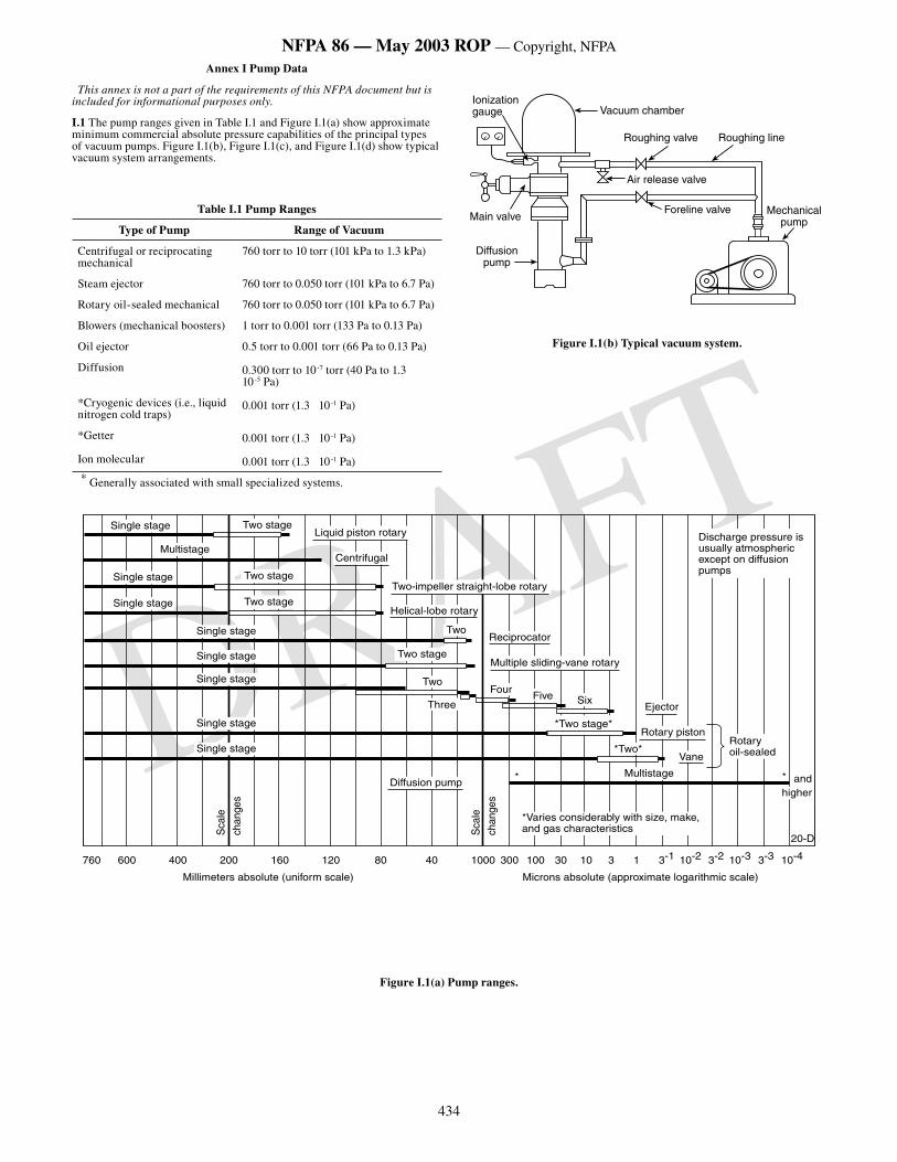
434
NFPA 86 — May 2003 ROP — Copyright, NFPA
DRAFT
Annex I Pump Data
This annex is not a part of the requirements of this NFPA document but is included for informational purposes only.
I.1 The pump ranges given in Table I.1 and Figure I.1(a) show approximate minimum commercial absolute pressure capabilities of the principal types of vacuum pumps. Figure I.1(b), Figure I.1(c), and Figure I.1(d) show typical vacuum system arrangements.
Table I.1 Pump Ranges
Type of Pump Range of Vacuum
Centrifugal or reciprocating mechanical
760 torr to 10 torr (101 kPa to 1.3 kPa)
Steam ejector 760 torr to 0.050 torr (101 kPa to 6.7 Pa)
Rotary oil-sealed mechanical 760 torr to 0.050 torr (101 kPa to 6.7 Pa)
Blowers (mechanical boosters) 1 torr to 0.001 torr (133 Pa to 0.13 Pa)
Oil ejector 0.5 torr to 0.001 torr (66 Pa to 0.13 Pa)
Diffusion 0.300 torr to 10-7 torr (40 Pa to 1.3 10-5 Pa)
*Cryogenic devices (i.e., liquid nitrogen cold traps)
0.001 torr (1.3 10-1 Pa)
*Getter 0.001 torr (1.3 10-1 Pa)
Ion molecular 0.001 torr (1.3 10-1 Pa)
* Generally associated with small specialized systems.
Mechanicalpump
Foreline valve
Air release valve
Roughing valve Roughing line
Vacuum chamberIonizationgauge
Main valve
Diffusionpump
Figure I.1(b) Typical vacuum system.
�������������������
�����������
���������������������
����������
������������
������������
������������
������������
������������
���������
���������
������������
������������
���������
��������������������
�����������
���������������������������������
���
���
������������
����������������������������
�������� ���
����������������������������������������������������������������
������������
���������
������������������������������
� ���������
�����������
����
������������������������������������������������������������
��������������
�����
����
���
�����
����
���
��� ��� ��� ��� ��� ��� �� �� ���� ��� ��� �� �� � �
������������������������������������ ������������������������������������������������
��� ���� ��� ���� ��� ����
Figure I.1(a) Pump ranges.
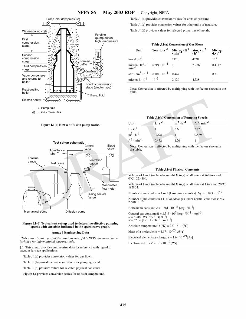
435
NFPA 86 — May 2003 ROP — Copyright, NFPA
DRAFT
Pump inlet (low pressure)
Water-cooling coils
First compressionstage
Second compressionstage
Third compressionstage
Vapor condensesand returns toboiler
Foreline baffle
Fourth compressionstage (ejector type)
Pump fluid
Fractionatingboiler
Electric heater
Foreline (pump outlet)high forepressure
�������������
����������������
Figure I.1(c) How a diffusion pump works.
Test set-up schematic
Admittancetube
Control valve
Bleed valve
Foreline gauge Test dome
Ionizationgauge
Mechanical pump Diffusion pump
O-ring sealedflange
Manometer flow meter
Figure I.1(d) Typical test set-up used to determine effective pumping speeds with variables indicated in the speed curve graph.
Annex J Engineering Data
This annex is not a part of the requirements of this NFPA document but is included for informational purposes only.
J.1 This annex provides engineering data for reference with regard to vacuum furnace applications.
Table J.1(a) provides conversion values for gas flows.
Table J.1(b) provides conversion values for pumping speed.
Table J.1(c) provides values for selected physical constants.
Figure J.1 provides conversion scales for units of temperature.
Table J.1(d) provides conversion values for units of pressure.
Table J.1(e) provides conversion values for other units of measure.
Table J.1(f) provides values for selected properties of metals.
Table J.1(a) Conversion of Gas Flows
Unit Torr ·L· s -1 Micron · ft3 · min-1
atm · cm3 · h-1
Micron ·L· s -1
torr ·L· s -1 1 2120 4738 103
micron · ft3·-min-1
4.719 · 10 -4 1 2.236 0.4719
atm · cm3 · h-1 2.110 · 10 -4 0.447 1 0.21
micron ·L· s-1 10 -3 2.120 4.738 1
Note: Conversion is effected by multiplying with the factors shown in the table.
Table J.1(b) Conversion of Pumping Speeds
Unit L · s -1 m3 · h-1 ft3 · min-1
L · s-1 1 3.60 2.12
m3 · h-1 0.278 1 0.589
ft3 · min-1 0.472 1.70 1
Note: Conversion is effected by multiplying with the factors shown in the table.
Table J.1(c) Physical Constants
Volume of 1 mol (molecular weight M in g) of all gases at 760 torr and 0°C: 22.416 L
Volume of 1 mol (molecular weight M in g) of all gases at 1 torr and 20°C: 18280 L
Number of molecules in 1 mol (Loschmidt number): NL = 6.023 · 1023
Number of molecules in 1 L of an ideal gas under normal conditions: N = 2.688 · 1022
Boltzmann constant: k = 1.381 · 10 -16 [erg · °K-1]
General gas constant:R = 8.315 · 107 [erg · °K-1 · mol-1] R = 8.315 [Ws · °K-1 · mol-1] R = 62.36 [torr · I · °K-1 · mol-1]
Absolute temperature: T[°K] = 273.16 + t[°C]
Mass of a molecule: µ = 1.67 · 10 -24 M [g]
Electrical elementary charge: e = 1.6 · 10 -19[As]
Electron volt: 1 eV = 1.6 · 10 -19[Ws]
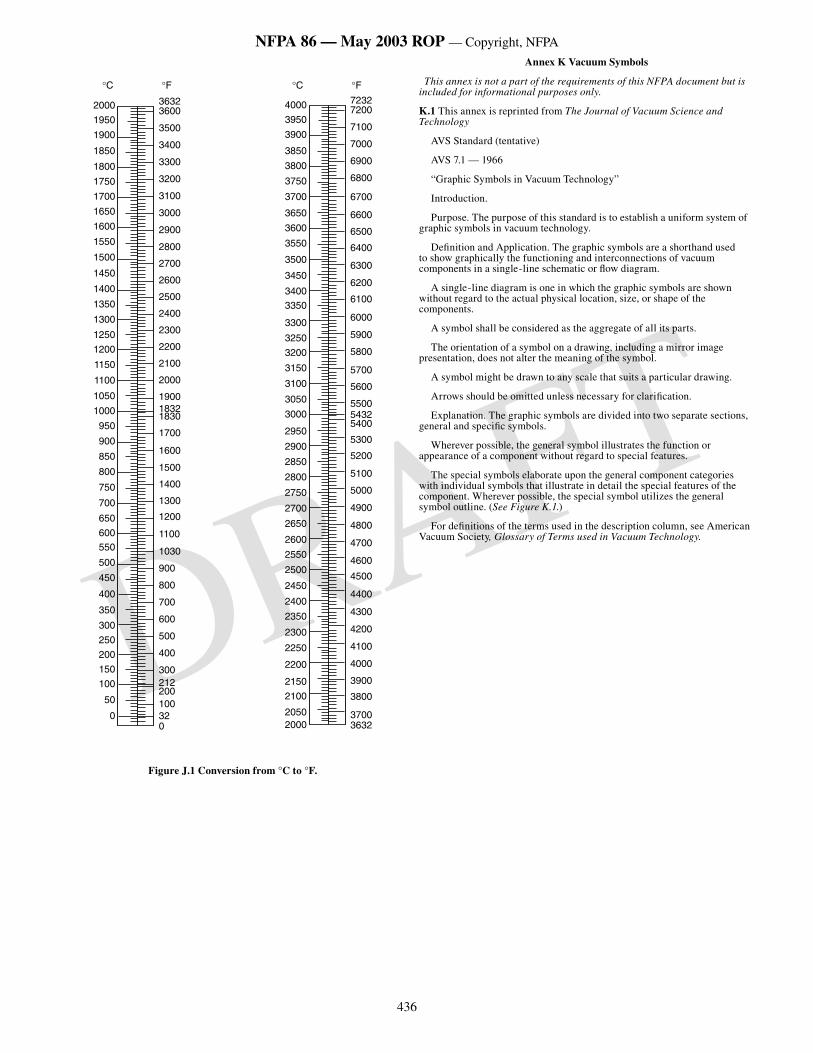
436
NFPA 86 — May 2003 ROP — Copyright, NFPA
DRAFT
2000
1950
1900
1850
1800
1750
1700
1650
1600
1550
1500
1450
1400
1350
1300
1250
1200
1150
1100
1050
1000
950
900
850
800
750
700
650
600
550
500
450
400
350
300
250
200
150
100
50
0
36323600
3500
3400
3300
3200
3100
3000
2900
2800
2700
2600
2500
2400
2300
2200
2100
2000
190018321830
1700
1600
1500
1400
1300
1200
1100
1030
900
800
700
600
���
���
������
������
���
����
����
����
����
����
����
����
����
����
����
����
����
����
����
����
����
����
����
����
����
����
����
����
����
����
����
����
����
����
����
����
����
����
����
����
����
����
����
����
��������
��������
����
����
����
����
����
����
����
����
����
����
����
����
����
����
����
����
����
��������
����
����
����
����
����
����
����
����
����
����
����
����
����
����
����
����
��������
°� °�°� °�
Figure J.1 Conversion from °C to °F.
Annex K Vacuum Symbols
This annex is not a part of the requirements of this NFPA document but is included for informational purposes only.
K.1 This annex is reprinted from The Journal of Vacuum Science and Technology
AVS Standard (tentative)
AVS 7.1 — 1966
“Graphic Symbols in Vacuum Technology”
Introduction.
Purpose. The purpose of this standard is to establish a uniform system of graphic symbols in vacuum technology.
Definition and Application. The graphic symbols are a shorthand used to show graphically the functioning and interconnections of vacuum components in a single-line schematic or flow diagram.
A single-line diagram is one in which the graphic symbols are shown without regard to the actual physical location, size, or shape of the components.
A symbol shall be considered as the aggregate of all its parts.
The orientation of a symbol on a drawing, including a mirror image presentation, does not alter the meaning of the symbol.
A symbol might be drawn to any scale that suits a particular drawing.
Arrows should be omitted unless necessary for clarification.
Explanation. The graphic symbols are divided into two separate sections, general and specific symbols.
Wherever possible, the general symbol illustrates the function or appearance of a component without regard to special features.
The special symbols elaborate upon the general component categories with individual symbols that illustrate in detail the special features of the component. Wherever possible, the special symbol utilizes the general symbol outline. (See Figure K.1.)
For definitions of the terms used in the description column, see American Vacuum Society, Glossary of Terms used in Vacuum Technology.
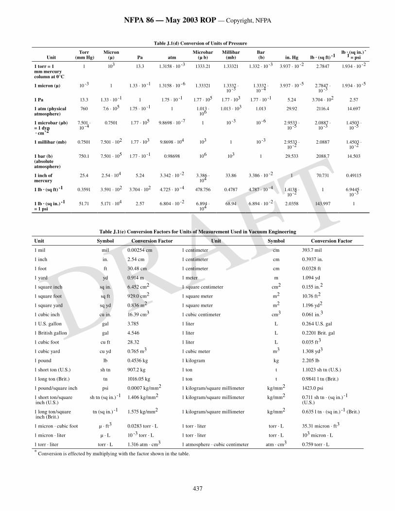
437
NFPA 86 — May 2003 ROP — Copyright, NFPA
DRAFT
Table J.1(d) Conversion of Units of Pressure
UnitTorr
(mm Hg)Micron
(µ) Pa atmMicrobar
(µ b)Millibar
(mb)Bar (b) in. Hg lb · (sq ft) -1
lb · (sq in.) -1 = psi
1 torr = 1 mm mercury column at 0°C
1 103 13.3 1.3158 · 10 -3 1333.21 1.33321 1.332 · 10 -3 3.937 · 10 -2 2.7847 1.934 · 10 -2
1 micron (µ) 10 -3 1 1.33 · 10 -1 1.3158 · 10 -6 1.33321 1.3332 · 10 -3
1.3332 · 10 -4
3.937 · 10 -5 2.7847 · 10 -3
1.934 · 10 -5
1 Pa 13.3 1.33 · 10 -1 1 1.75 · 10 -1 1.77 · 105 1.77 · 103 1.77 · 10 -1 5.24 3.704 · 102 2.57
1 atm (physical atmosphere)
760 7.6 · 105 1.75 · 10 -1 1 1.013 · 106
1.013 · 103 1.013 29.92 2116.4 14.697
1 microbar (µb) = 1 dyn · cm-2
7.501 · 10 -4
0.7501 1.77 · 105 9.8698 · 10 -7 1 10 -3 10 -6 2.9533 · 10 -5
2.0887 · 10 -3
1.4503 · 10 -5
1 millibar (mb) 0.7501 7.501 · 102 1.77 · 103 9.8698 · 104 103 1 10 -3 2.9533 · 10 -2
2.0887 1.4503 · 10 -2
1 bar (b) (absolute atmosphere)
750.1 7.501 · 105 1.77 · 10 -1 0.98698 106 103 1 29.533 2088.7 14.503
1 inch of mercury
25.4 2.54 · 104 5.24 3.342 · 10 -2 3.386 · 104
33.86 3.386 · 10 -2 1 70.731 0.49115
1 lb · (sq ft) -1 0.3591 3.591 · 102 3.704 · 102 4.725 · 10 -4 478.756 0.4787 4.787 · 10 -4 1.4138 · 10 -2
1 6.9445 · 10 -3
1 lb · (sq in.) -1 = 1 psi
51.71 5.171 · 104 2.57 6.804 · 10 -2 6.894 · 104
68.94 6.894 · 10 -2 2.0358 143.997 1
Table J.1(e) Conversion Factors for Units of Measurement Used in Vacuum Engineering
Unit Symbol Conversion Factor Unit Symbol Conversion Factor
1 mil mil 0.00254 cm 1 centimeter cm 393.7 mil
1 inch in. 2.54 cm 1 centimeter cm 0.3937 in.
1 foot ft 30.48 cm 1 centimeter cm 0.0328 ft
1 yard yd 0.914 m 1 meter m 1.094 yd
1 square inch sq in. 6.452 cm2 1 square centimeter cm2 0.155 in.2
1 square foot sq ft 929.0 cm2 1 square meter m2 10.76 ft2
1 square yard sq yd 0.836 m2 1 square meter m2 1.196 yd2
1 cubic inch cu in. 16.39 cm3 1 cubic centimeter cm3 0.061 in.3
1 U.S. gallon gal 3.785 1 liter L 0.264 U.S. gal
1 British gallon gal 4.546 1 liter L 0.2201 Brit. gal
1 cubic foot cu ft 28.32 1 liter L 0.035 ft3
1 cubic yard cu yd 0.765 m3 1 cubic meter m3 1.308 yd3
1 pound lb 0.4536 kg 1 kilogram kg 2.205 lb
1 short ton (U.S.) sh tn 907.2 kg 1 ton t 1.1023 sh tn (U.S.)
1 long ton (Brit.) tn 1016.05 kg 1 ton t 0.9841 l tn (Brit.)
1 pound/square inch psi 0.0007 kg/mm2 1 kilogram/square millimeter kg/mm2 1423.0 psi
1 short ton/square inch (U.S.)
sh tn (sq in.) -1 1.406 kg/mm2 1 kilogram/square millimeter kg/mm2 0.711 sh tn · (sq in.) -1 (U.S.)
1 long ton/square inch (Brit.)
tn (sq in.) -1 1.575 kg/mm2 1 kilogram/square millimeter kg/mm2 0.635 l tn · (sq in.) -1 (Brit.)
1 micron · cubic foot µ · ft3 0.0283 torr · L 1 torr · liter torr · L 35.31 micron · ft3
1 micron · liter µ · L 10 -3 torr · L 1 torr · liter torr · L 103 micron · L
1 torr · liter torr · L 1.316 atm · cm3 1 atmosphere · cubic centimeter atm · cm3 0.759 torr · L
* Conversion is effected by multiplying with the factor shown in the table.
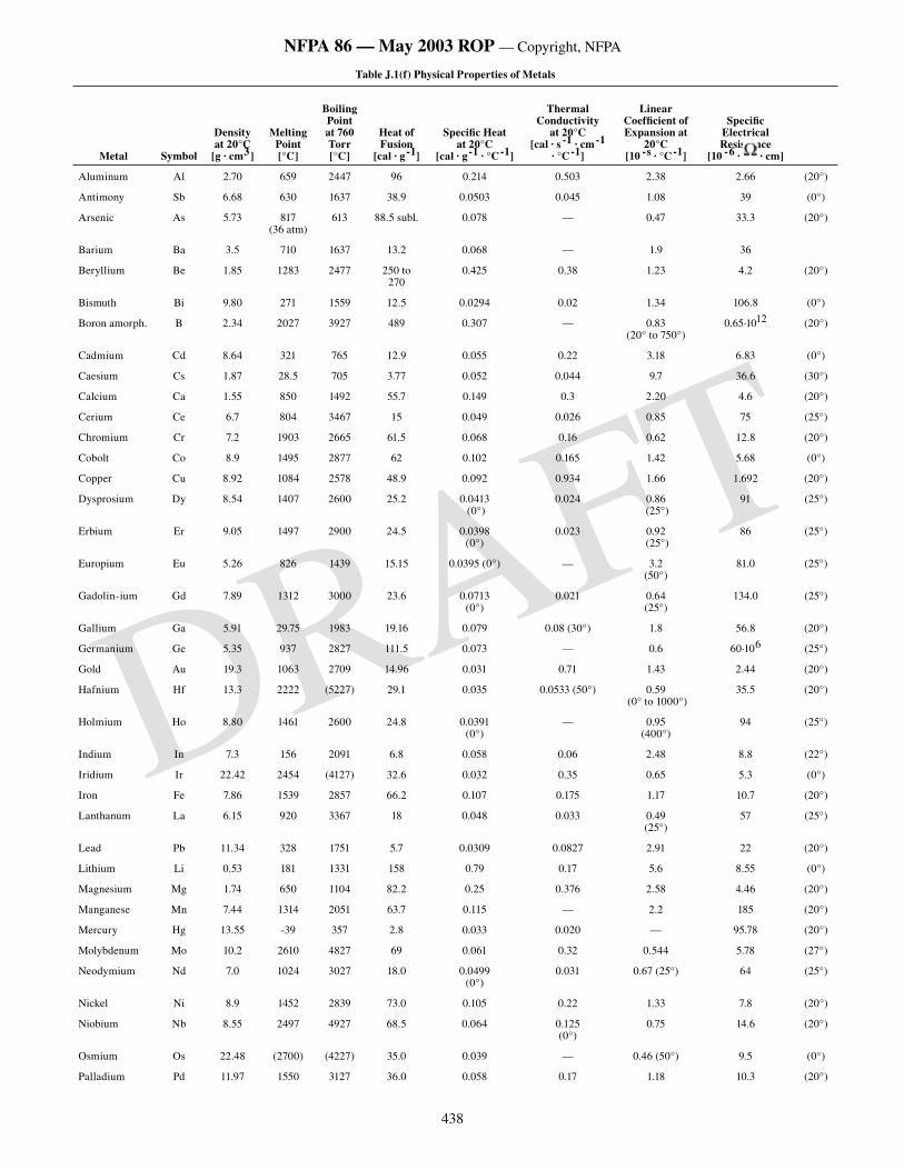
438
NFPA 86 — May 2003 ROP — Copyright, NFPA
DRAFT
Table J.1(f) Physical Properties of Metals
Metal Symbol
Density at 20°C
[g · cm3]
Melting Point [°C]
Boiling Point at 760 Torr [°C]
Heat of Fusion
[cal · g-1]
Specific Heatat 20°C
[cal · g-1 · °C-1]
Thermal Conductivity
at 20°C[cal · s -1 · cm-1
· °C-1]
Linear Coefficient of Expansion at
20°C[10 -s · °C-1]
Specific Electrical Resistance
[10 -6 · · cm]
Aluminum Al 2.70 659 2447 96 0.214 0.503 2.38 2.66 (20°)
Antimony Sb 6.68 630 1637 38.9 0.0503 0.045 1.08 39 (0°)
Arsenic As 5.73 817(36 atm)
613 88.5 subl. 0.078 — 0.47 33.3 (20°)
Barium Ba 3.5 710 1637 13.2 0.068 — 1.9 36
Beryllium Be 1.85 1283 2477 250 to270
0.425 0.38 1.23 4.2 (20°)
Bismuth Bi 9.80 271 1559 12.5 0.0294 0.02 1.34 106.8 (0°)
Boron amorph. B 2.34 2027 3927 489 0.307 — 0.83(20° to 750°)
0.65·1012 (20°)
Cadmium Cd 8.64 321 765 12.9 0.055 0.22 3.18 6.83 (0°)
Caesium Cs 1.87 28.5 705 3.77 0.052 0.044 9.7 36.6 (30°)
Calcium Ca 1.55 850 1492 55.7 0.149 0.3 2.20 4.6 (20°)
Cerium Ce 6.7 804 3467 15 0.049 0.026 0.85 75 (25°)
Chromium Cr 7.2 1903 2665 61.5 0.068 0.16 0.62 12.8 (20°)
Cobolt Co 8.9 1495 2877 62 0.102 0.165 1.42 5.68 (0°)
Copper Cu 8.92 1084 2578 48.9 0.092 0.934 1.66 1.692 (20°)
Dysprosium Dy 8.54 1407 2600 25.2 0.0413 (0°)
0.024 0.86 (25°)
91 (25°)
Erbium Er 9.05 1497 2900 24.5 0.0398 (0°)
0.023 0.92 (25°)
86 (25°)
Europium Eu 5.26 826 1439 15.15 0.0395 (0°) — 3.2 (50°)
81.0 (25°)
Gadolin-ium Gd 7.89 1312 3000 23.6 0.0713 (0°)
0.021 0.64(25°)
134.0 (25°)
Gallium Ga 5.91 29.75 1983 19.16 0.079 0.08 (30°) 1.8 56.8 (20°)
Germanium Ge 5.35 937 2827 111.5 0.073 — 0.6 60·106 (25°)
Gold Au 19.3 1063 2709 14.96 0.031 0.71 1.43 2.44 (20°)
Hafnium Hf 13.3 2222 (5227) 29.1 0.035 0.0533 (50°) 0.59 (0° to 1000°)
35.5 (20°)
Holmium Ho 8.80 1461 2600 24.8 0.0391 (0°)
— 0.95 (400°)
94 (25°)
Indium In 7.3 156 2091 6.8 0.058 0.06 2.48 8.8 (22°)
Iridium Ir 22.42 2454 (4127) 32.6 0.032 0.35 0.65 5.3 (0°)
Iron Fe 7.86 1539 2857 66.2 0.107 0.175 1.17 10.7 (20°)
Lanthanum La 6.15 920 3367 18 0.048 0.033 0.49 (25°)
57 (25°)
Lead Pb 11.34 328 1751 5.7 0.0309 0.0827 2.91 22 (20°)
Lithium Li 0.53 181 1331 158 0.79 0.17 5.6 8.55 (0°)
Magnesium Mg 1.74 650 1104 82.2 0.25 0.376 2.58 4.46 (20°)
Manganese Mn 7.44 1314 2051 63.7 0.115 — 2.2 185 (20°)
Mercury Hg 13.55 -39 357 2.8 0.033 0.020 — 95.78 (20°)
Molybdenum Mo 10.2 2610 4827 69 0.061 0.32 0.544 5.78 (27°)
Neodymium Nd 7.0 1024 3027 18.0 0.0499 (0°)
0.031 0.67 (25°) 64 (25°)
Nickel Ni 8.9 1452 2839 73.0 0.105 0.22 1.33 7.8 (20°)
Niobium Nb 8.55 2497 4927 68.5 0.064 0.125 (0°)
0.75 14.6 (20°)
Osmium Os 22.48 (2700) (4227) 35.0 0.039 — 0.46 (50°) 9.5 (0°)
Palladium Pd 11.97 1550 3127 36.0 0.058 0.17 1.18 10.3 (20°)
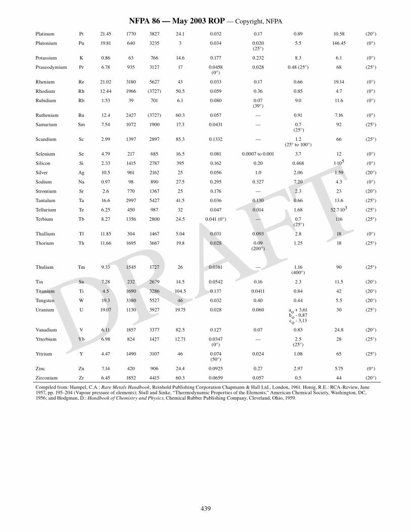
439
NFPA 86 — May 2003 ROP — Copyright, NFPA
DRAFT
Platinum Pt 21.45 1770 3827 24.1 0.032 0.17 0.89 10.58 (20°)
Plutonium Pu 19.81 640 3235 3 0.034 0.020 (25°)
5.5 146.45 (0°)
Potassium K 0.86 63 766 14.6 0.177 0.232 8.3 6.1 (0°)
Praseodymium Pr 6.78 935 3127 17 0.0458 (0°)
0.028 0.48 (25°) 68 (25°)
Rhenium Re 21.02 3180 5627 43 0.033 0.17 0.66 19.14 (0°)
Rhodium Rh 12.44 1966 (3727) 50.5 0.059 0.36 0.85 4.7 (0°)
Rubidium Rb 1.53 39 701 6.1 0.080 0.07 (39°)
9.0 11.6 (0°)
Ruthenium Ru 12.4 2427 (3727) 60.3 0.057 — 0.91 7.16 (0°)
Samarium Sm 7.54 1072 1900 17.3 0.0431 — 0.7 (25°)
92 (25°)
Scandium Sc 2.99 1397 2897 85.3 0.1332 — 1.2 (25° to 100°)
66 (25°)
Selenium Se 4.79 217 685 16.5 0.081 0.0007 to 0.001 3.7 12 (0°)
Silicon Si 2.33 1415 2787 395 0.162 0.20 0.468 1·105 (0°)
Silver Ag 10.5 961 2162 25 0.056 1.0 2.06 1.59 (20°)
Sodium Na 0.97 98 890 27.5 0.295 0.327 7.20 4.3 (0°)
Strontium Sr 2.6 770 1367 25 0.176 — 2.3 23 (20°)
Tantalum Ta 16.6 2997 5427 41.5 0.036 0.130 0.66 13.6 (25°)
Tellurium Te 6.25 450 987 32 0.047 0.014 1.68 52.7·103 (25°)
Terbium Tb 8.27 1356 2800 24.5 0.041 (0°) — 0.7 (25°)
116 (25°)
Thallium Tl 11.85 304 1467 5.04 0.031 0.093 2.8 18 (0°)
Thorium Th 11.66 1695 3667 19.8 0.028 0.09 (200°)
1.25 18 (25°)
Thulium Tm 9.33 1545 1727 26 0.0381 — 1.16 (400°)
90 (25°)
Tin Sn 7.28 232 2679 14.5 0.0542 0.16 2.3 11.5 (20°)
Titanium Ti 4.5 1690 3286 104.5 0.137 0.0411 0.84 42 (20°)
Tungsten W 19.3 3380 5527 46 0.032 0.40 0.44 5.5 (20°)
Uranium U 19.07 1130 3927 19.75 0.028 0.060 ao + 3,61 bo - 0,87 co - 3,13
30 (25°)
Vanadium V 6.11 1857 3377 82.5 0.127 0.07 0.83 24.8 (20°)
Ytterbium Yb 6.98 824 1427 12.71 0.0347 (0°)
— 2.5 (25°)
28 (25°)
Yttrium Y 4.47 1490 3107 46 0.074 (50°)
0.024 1.08 65 (25°)
Zinc Zn 7.14 420 906 24.4 0.0925 0.27 2.97 5.75 (0°)
Zirconium Zr 6.45 1852 4415 60.3 0.0659 0.057 0.5 44 (20°)
Compiled from: Hampel, C.A.: Rare Metals Handbook, Reinhold Publishing Corporation Chapmann & Hall Ltd., London, 1961. Honig, R.E.: RCA-Review, June 1957, pp. 195-204 (Vapour pressure of elements); Stull and Sinke, “Thermodynamic Properties of the Elements,” American Chemical Society, Washington, DC, 1956; and Hodgman, D.: Handbook of Chemistry and Physics, Chemical Rubber Publishing Company, Cleveland, Ohio, 1959.
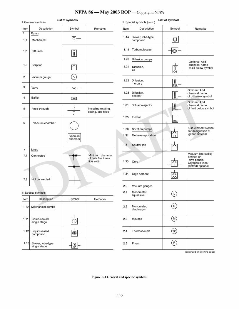
440
NFPA 86 — May 2003 ROP — Copyright, NFPA
DRAFT
����
�������������������������������������
�������������
����������� ������ �������
������������������List of symbols
�
���
���
���
����
����������
���������
��������
�
�
�
�
� ��������������
������������
������
�����
������������
��������������������������������������������
�
���
���
�����
���������
�������������
���� ����������� ������ �������
���������������������������List of symbols
����
����
�������������������������
��������������
����
����
����
����
���������������
�����������������
�����������������
�������������
����
����
�����������������
�������
����
����
���
��������������
������������������
�����������
����
������������
����
����
���
���
�������������
����������������������
���������������������������������������������������������������������������
���������������������������������������������������
������������������������������������������������
����������������������������������������������
���
��
�
����������������������������������������������
��
�
��� �������������������
���
���
���
������
������������
������
�
�
��
�
�����������������������������
���� ����������� ������ �������
�������������������
����
����
����
����
����������������
��������������������������
����������������������
�����������������������������
Figure K.1 General and specific symbols.
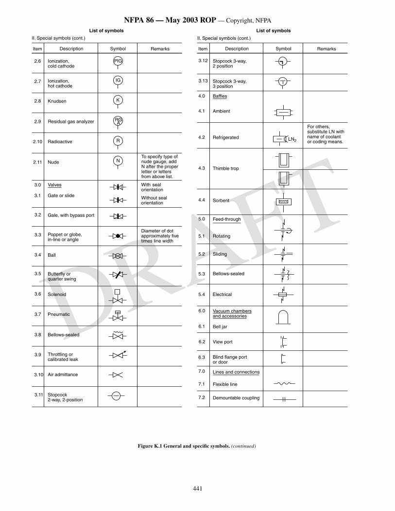
441
NFPA 86 — May 2003 ROP — Copyright, NFPA
DRAFT
���� ����������� ������ �������
List of symbols
���� ����������� ������ �������
���������������������������
List of symbols
���������������������������
���
��
�
����
�
�
���
���
���
��� ���������������������
�������
����������������������
�����������������������
����
����
���
���
�����������
����
������
�������������
��������������������������������������������������������������������������������������
����������������������
������������������������
���� ��������������������������
������������������
���
���
����������������������������
��������������
���
���
���
���������
��������
�������������������������
�������
���
���
��������������������������������
����������������������
�������������������������������������������������
���� ��������������������������
���� ��������������������������
���
���
�������
�������
����������������������������������������������������������������
�����������
���
���
��� ����������
��������������
�������
���
���
���
���
������������
������������
�������
������������
���
��� ��������
���
���
���
���������
������������������������
���������������������
����������������
��� ��������������������
������������������������������
Figure K.1 General and specific symbols. (continued)
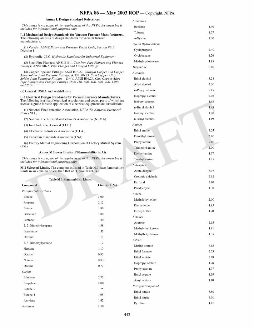
442
NFPA 86 — May 2003 ROP — Copyright, NFPA
DRAFT
Annex L Design Standard References
This annex is not a part of the requirements of this NFPA document but is included for informational purposes only.
L.1 Mechanical Design Standards for Vacuum Furnace Manufacturers. The following are lists of design standards for vacuum furnace manufacturers:
(1) Vessels: ASME Boiler and Pressure Vessel Code, Section VIII, Division 1
(2) Hydraulic: J.I.C. Hydraulic Standards for Industrial Equipment
(3) Steel Pipe Flanges: ANSI B16.1, Cast Iron Pipe Flanges and Flanged Fittings; ANSI B16.5, Pipe Flanges and Flanged Fittings
(4) Copper Pipe and Fittings: ANSI B16.22 , Wrought Copper and Copper Alloy Solder Joint Pressure Fittings; ANSI B16.23, Cast Copper Alloy Solder Joint Drainage Fittings —DWV; ANSI B16.24, Cast Copper Alloy Pipe Flanges and Flanged Fittings Class 150, 300, 400, 600, 900, 1500, and 2500
(5) General: OSHA and Walsh/Healy
L.2 Electrical Design Standards for Vacuum Furnace Manufacturers. The following is a list of electrical associations and codes, parts of which are used as a guide for safe application of electrical equipment and installation:
(1) National Fire Protection Association, NFPA 70, National Electrical Code (NEC)
(2) National Electrical Manufacturer’s Association (NEMA)
(3) Joint Industrial Council (J.I.C.)
(4) Electronic Industries Association (E.I.A.)
(5) Canadian Standards Association (CSA)
(6) Factory Mutual Engineering Corporation of Factory Mutual System (FM)
Annex M Lower Limits of Flammability in Air
This annex is not a part of the requirements of this NFPA document but is included for informational purposes only.
M.1 Selected Limits. The compounds listed in Table M.1 have flammability limits in air equal to or less than that of H
2 (=4.00 vol. %).
Table M.1 Flammability Limits
Compound Limit (vol. %)
Parafin Hydrocarbons
Ethane 3.00
Propane 2.12
Butane 1.86
Isobutane 1.80
Pentane 1.40
2, 2-Dimethylpropane 1.38
Isopentane 1.32
Hexane 1.18
2, 3-Dimethylpentane 1.12
Heptane 1.10
Octane 0.95
Nonane 0.83
Decane 0.77
Olefins
Ethylene 2.75
Propylene 2.00
Butene-2 1.75
Butene-1 1.65
Amylene 1.42
Acetylene 2.50
Aromatics
Benzene 1.40
Toluene 1.27
o-Xylene 1.00
Cyclin Hydrocarbons
Cyclopropane 2.40
Cyclohexane 1.26
Methylcyclohexane 1.15
Turpentine 0.80
Alcohols
Ethyl alcohol 3.28
Allyl alcohol 2.50
n-Propyl alcohol 2.15
Isopropyl alcohol 2.02
Isobutyl alcohol 1.68
n-Butyl alcohol 1.45
Isoamyl alcohol 1.20
n-Amyl alcohol 1.19
Amines
Ethyl amine 3.55
Dimethyl amine 2.80
Propyl amine 2.01
Trimethyl amine 2.00
Diethyl amine 1.77
Triethyl amine 1.25
Aldehydes
Acetaldehyde 3.97
Crotonic aldehyde 2.12
Furfural 2.10
Paraldehyde 1.30
Ethers
Methylethyl ether 2.00
Diethyl ether 1.85
Divinyl ether 1.70
Ketones
Acetone 2.55
Methylethyl ketone 1.81
Methylbutyl ketone 1.35
Esters
Methyl acetate 3.15
Ethyl formate 2.75
Ethyl acetate 2.18
Isopropyl acetate 1.78
Propyl acetate 1.77
Butyl acetate 1.39
Amyl acetate 1.10
Nitrogen Compound
Ethyl nitrate 3.80
Ethyl nitrite 3.01
Pyridine 1.81
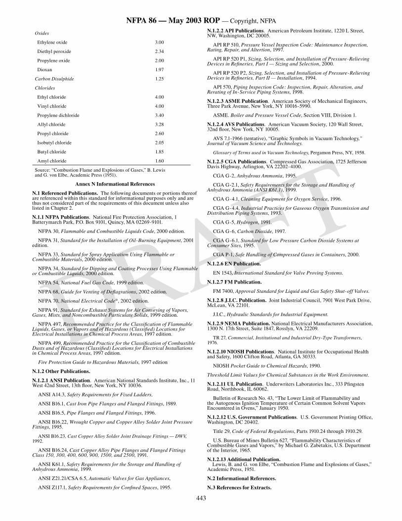
443
NFPA 86 — May 2003 ROP — Copyright, NFPA
DRAFT
Oxides
Ethylene oxide 3.00
Diethyl peroxide 2.34
Propylene oxide 2.00
Dioxan 1.97
Carbon Disulphide 1.25
Chlorides
Ethyl chloride 4.00
Vinyl chloride 4.00
Propylene dichloride 3.40
Allyl chloride 3.28
Propyl chloride 2.60
Isobutyl chloride 2.05
Butyl chloride 1.85
Amyl chloride 1.60
Source: “Combustion Flame and Explosions of Gases,” B. Lewis and G. von Elbe, Academic Press (1951).
Annex N Informational References
N.1 Referenced Publications. The following documents or portions thereof are referenced within this standard for informational purposes only and are thus not considered part of the requirements of this document unless also listed in Chapter 2.
N.1.1 NFPA Publications. National Fire Protection Association, 1 Batterymarch Park, P.O. Box 9101, Quincy, MA 02269-9101.
NFPA 30, Flammable and Combustible Liquids Code, 2000 edition.
NFPA 31, Standard for the Installation of Oil-Burning Equipment, 2001 edition.
NFPA 33, Standard for Spray Application Using Flammable or Combustible Materials, 2000 edition.
NFPA 34, Standard for Dipping and Coating Processes Using Flammable or Combustible Liquids, 2000 edition.
NFPA 54, National Fuel Gas Code, 1999 edition.
NFPA 68, Guide for Venting of Deflagrations, 2002 edition.
NFPA 70, National Electrical Code®, 2002 edition.
NFPA 91, Standard for Exhaust Systems for Air Conveying of Vapors, Gases, Mists, and Noncombustible Particulate Solids, 1999 edition.
NFPA 497, Recommended Practice for the Classification of Flammable Liquids, Gases, or Vapors and of Hazardous (Classified) Locations for Electrical Installations in Chemical Process Areas, 1997 edition.
NFPA 499, Recommended Practice for the Classification of Combustible Dusts and of Hazardous (Classified) Locations for Electrical Installations in Chemical Process Areas, 1997 edition.
Fire Protection Guide to Hazardous Materials, 1997 edition
N.1.2 Other Publications.
N.1.2.1 ANSI Publication. American National Standards Institute, Inc., 11 West 42nd Street, 13th floor, New York, NY 10036.
ANSI A14.3, Safety Requirements for Fixed Ladders,
ANSI B16.1, Cast Iron Pipe Flanges and Flanged Fittings, 1989.
ANSI B16.5, Pipe Flanges and Flanged Fittings, 1996.
ANSI B16.22, Wrought Copper and Copper Alloy Solder Joint Pressure Fittings, 1995.
ANSI B16.23, Cast Copper Alloy Solder Joint Drainage Fittings — DWV, 1992.
ANSI B16.24, Cast Copper Alloy Pipe Flanges and Flanged Fittings Class 150, 300, 400, 600, 900, 1500, and 2500, 1991.
ANSI K61.1, Safety Requirements for the Storage and Handling of Anhydrous Ammonia, 1999.
ANSI Z21.21/CSA 6.5, Automatic Valves for Gas Appliances,
ANSI Z117.1, Safety Requirements for Confined Spaces, 1995.
N.1.2.2 API Publications. American Petroleum Institute, 1220 L Street, NW, Washington, DC 20005.
API RP 510, Pressure Vessel Inspection Code: Maintenance Inspection, Rating, Repair, and Altertion, 1997.
API RP 520 P1, Sizing, Selection, and Installation of Pressure-Relieving Devices in Refineries, Part I — Sizing and Selection, 2000.
API RP 520 P2, Sizing, Selection, and Installation of Pressure-Relieving Devices in Refineries, Part II — Installation, 1994.
API 570, Piping Inspection Code: Inspection, Repair, Alteration, and Rerating of In-Service Piping Systems, 1998.
N.1.2.3 ASME Publication. American Society of Mechanical Engineers, Three Park Avenue, New York, NY 10016-5990.
ASME. Boiler and Pressure Vessel Code, Section VIII, Division 1.
N.1.2.4 AVS Publications. American Vacuum Society, 120 Wall Street, 32nd floor, New York, NY 10005.
AVS 7.1-1966 (tentative), “Graphic Symbols in Vacuum Technology,” Journal of Vacuum Science and Technology.
Glossary of Terms used in Vacuum Technology, Pergamon Press, NY, 1958.
N.1.2.5 CGA Publications. Compressed Gas Association, 1725 Jefferson Davis Highway, Arlington, VA 22202-4100.
CGA G-2, Anhydrous Ammonia, 1995.
CGA G-2.1, Safety Requirements for the Storage and Handling of Anhydrous Ammonia (ANSI K61.1), 1999.
CGA G-4.1, Cleaning Equipment for Oxygen Service, 1996.
CGA G-4.4, Industrial Practices for Gaseous Oxygen Transmission and Distribution Piping Systems, 1993.
CGA G-5, Hydrogen, 1991.
CGA G-6, Carbon Dioxide, 1997.
CGA G-6.1, Standard for Low Pressure Carbon Dioxide Systems at Consumer Sites, 1995.
CGA P-1, Safe Handling of Compressed Gases in Containers, 2000.
N.1.2.6 EN Publication.
EN 1543, International Standard for Valve Proving Systems.
N.1.2.7 FM Publication.
FM 7400, Approval Standard for Liquid and Gas Safety Shut-off Valves.
N.1.2.8 J.I.C. Publication. Joint Industrial Council, 7901 West Park Drive, McLean, VA 22101.
J.I.C., Hydraulic Standards for Industrial Equipment.
N.1.2.9 NEMA Publication. National Electrical Manufacturers Association, 1300 N. 17th Street, Suite 1847, Rosslyn, VA 22209.
TR 27, Commercial, Institutional and Industrial Dry-Type Transformers, 1976.
N.1.2.10 NIOSH Publications. National Institute for Occupational Health and Safety, 1600 Clifton Road, Atlanta, GA 30333.
NIOSH Pocket Guide to Chemical Hazards, 1990.
Threshold Limit Values for Chemical Substances in the Work Environment.
N.1.2.11 UL Publication. Underwriters Laboratories Inc., 333 Pfingsten Road, Northbook, IL 60062.
Bulletin of Research No. 43, “The Lower Limit of Flammability and the Autogenous Ignition Temperature of Certain Common Solvent Vapors Encountered in Ovens,” January 1950.
N.1.2.12 U.S. Government Publications. U.S. Government Printing Office, Washington, DC 20402.
Title 29, Code of Federal Regulations, Parts 1910.24 through 1910.29.
U.S. Bureau of Mines Bulletin 627, “Flammability Characteristics of Combustible Gases and Vapors,” by Michael G. Zabetakis, U.S. Department of the Interior, 1965.
N.1.2.13 Additional Publication. Lewis, B. and G. von Elbe, “Combustion Flame and Explosions of Gases,” Academic Press, 1951.
N.2 Informational References.
N.3 References for Extracts.