requirements for machinery equipment machine … for machinery equipment machine run off and...
TRANSCRIPT

File Name: doc name: PT_TS_QA_MRO v 1.2 vers: 1.2 Page No.: 1 of 58 Original Date: 21-febr 11 Revised Date: 24 Mar 2011
Requirements for Machinery Equipment
Machine Run Off
And
Acceptance Specifications
(MRO)
Document No.: FP-CPT_Q_MRO
Version 1.2
Original date: 21 February 2011
Revised date: 24 March 2011
THIS IS A COMMON DOCUMENT VALID WITHIN
FIAT POWERTRAIN SPA AND CHRYSLER POWERTRAIN LLC

File Name: doc name: PT_TS_QA_MRO v 1.2 vers: 1.2 Page No.: 2 of 58 Original Date: 21-febr 11 Revised Date: 24 Mar 2011
The controlled version of this document is available on the following Fiat Powertrain SpA and Chrysler Powertrain LLC web sites:
http://supplierinfo.fptpowertrain.com/index.php
https://gsp.extra.chrysler.com/mfg/amedd/powertrain.htm
Any printed copy is an uncontrolled copy. The user shall verify with the web site that he/she is in fact using the appropriate version of the specification for the specific project he/she is working on.
Any questions or comments with respect to this specification should be directed to the project engineer for the specific project in question.
Revision Date Version No. Description Paragraph Effected Released By
21 febr-11 1.0 Document creation All Rubino-Panniello 21 Mar 11 1.1 Substitution of:
the FPT logo with the FP logo, the acronym FPT with the FP-CHP (1); update the Washing Machines paragraph; paragraphs reordering and other minor changes done
All - 3.6 Rubino - Carle – Leonte
24 Mar 11 1.2 Added paragraph for Cylinder block Honing Machines
3.4.14 Colonna
The number to the left of the decimal in the version number indicates the major version number.
The number to the right of the decimal in the version number indicates the minor version number.
The major version number will change for the following reasons:
• Information added to document.
• Information removed from document.
• Rearrangement of sections in the document.
• Revisions to the scope or purpose of the document.
The minor version number will change for the following reason:
Minor changes that do not affect the overall scope of the document.
1 In the document it is used “FP” acronym for “Fiat Powertrain SpA and “CPT” acronym for Chrysler Powertrain LLC.

File Name: doc name: PT_TS_QA_MRO v 1.2 vers: 1.2 Page No.: 3 of 58 Original Date: 21-febr 11 Revised Date: 24 Mar 2011
CONTENTS
1 INTRODUCTION..................................................................................................................5 1.1 SCOPE OF DOCUMENT..................................................................................................................... 5 1.1.1 Local range of application ............................................................................................................. 5 1.1.2 Subject-related range of application ............................................................................................... 5 1.1.3 Procedural flow chart for preliminary and final acceptance ............................................................... 6
2 APPLICABLE DOCUMENTS ..................................................................................................7 2.1 ORDER OF PRECEDENCE.................................................................................................................. 7 2.2 GOVERNMENT DOCUMENTS............................................................................................................. 7 2.2.1 European Union ........................................................................................................................... 7 2.2.2 Other .......................................................................................................................................... 7 2.3 INDUSTRY STANDARDS ................................................................................................................... 7 2.4 FP-CPT DOCUMENTS ....................................................................................................................... 7 2.5 OTHER DOCUMENTS ....................................................................................................................... 7
3 REQUIREMENTS..................................................................................................................8 3.1 MANAGEMENT OF ACCEPTANCE PROCEDURE .................................................................................... 8 3.2 PREPARATION................................................................................................................................. 8 3.2.1 Part Availability ............................................................................................................................ 9 3.2.2 Pre-Conditions.............................................................................................................................. 9 3.3 PRELIMINARY QUALITY ACCEPTANCE (SUPPLIER’S PLANT) .............................................................. 13 3.3.1 Equipment Pre-Qualification ........................................................................................................ 13 3.3.2 Capability Run............................................................................................................................ 13 3.3.3 Common-Sense Appraisal............................................................................................................ 16 3.3.4 Report Generation ...................................................................................................................... 18 3.3.5 Tool-Change Capability ............................................................................................................... 18 3.3.6 Important Note For Machine Delivery ........................................................................................... 18 3.3.7 Equipment Non-Conformance ...................................................................................................... 18 3.3.8 Acceptance Of Parallel CNC Machining Centers.............................................................................. 19 3.4 SPECIAL CONDITIONS ................................................................................................................... 20 3.4.1 General Note.............................................................................................................................. 20 3.4.2 Surface Roughness ..................................................................................................................... 20 3.4.3 Unilaterally Limited Characteristics ............................................................................................... 20 3.4.4 GEARS and SPLINES (Including those on Shafts)........................................................................... 20 3.4.5 Tool Wear.................................................................................................................................. 21 3.4.6 Hardness ................................................................................................................................... 21 3.4.7 Positional Tolerances .................................................................................................................. 22 3.4.8 Deep-Fillet-Rolling and Roll-Straightening ..................................................................................... 22 3.4.9 Balancing Machines .................................................................................................................... 24 3.4.10 100% Automatic Gaging ............................................................................................................. 24 3.4.11 Modification / Relocation of manufacturing equipments ................................................................. 25 3.4.12 Straightening Machine ................................................................................................................ 26 3.4.13 Welding Machines....................................................................................................................... 26 3.4.14 Cylinder Block Honing Machines................................................................................................... 27 3.4.15 Washing Machines – see sect. 3.6................................................................................................ 27 3.5 FINAL QUALITY ACCEPTANCE (FP-CPT PLANT) ................................................................................ 27 3.5.1 General ..................................................................................................................................... 27 3.5.2 Capability run............................................................................................................................. 27 3.5.3 Final acceptance of parallel operations (at FP-CPT facility) ............................................................. 28

File Name: doc name: PT_TS_QA_MRO v 1.2 vers: 1.2 Page No.: 4 of 58 Original Date: 21-febr 11 Revised Date: 24 Mar 2011
3.6 WASHING MACHINES..................................................................................................................... 29 3.6.1 Pre-conditions (see also general requirements on section 3) ......................................................... 29 3.6.2 Preliminary acceptance (at the supplier plant).............................................................................. 29 3.6.3 Washing Machines Final Acceptance Run Off (at the customer plant )........................................ 30
4 SPECIFICATION VALIDATION ......................................................................................... 33 4.1 NOTE FOR FINAL PAYMENT............................................................................................................ 33
5 NOTES.............................................................................................................................. 33 5.1 GLOSSARY .................................................................................................................................... 33 5.2 ABBREVIATIONS, ACRONYMS AND SYMBOLS .................................................................................. 33 5.3 REFERENCE DOCUMENTS............................................................................................................... 33
6 APPENDIX........................................................................................................................ 34 6.1 BASIS OF CALCULATION ................................................................................................................ 34 6.1.1 (refer 3.2.2.3 Pre-Run Tests)...................................................................................................... 34 6.1.2 Process Capability....................................................................................................................... 35 6.1.3 Stability ..................................................................................................................................... 35 6.1.4 shewhart chart with extended limits ............................................................................................. 35 6.2 EVALUATION OF POSITIONAL TOLERANCES.................................................................................... 37 6.2.1 Tolerance Zone .......................................................................................................................... 37 6.2.2 Studying Positional Tolerances Using The True Position Value ........................................................ 37 6.2.3 Positional Capability Using Data Without Reference To Correlation.................................................. 38 6.2.4 Po/Pok capability indices............................................................................................................ 38 6.3 CONFIGURATION OF EVALUATION ................................................................................................. 40 6.3.1 Process capability ....................................................................................................................... 40 6.3.2 Sample Analysis ......................................................................................................................... 54

File Name: doc name: PT_TS_QA_MRO v 1.2 vers: 1.2 Page No.: 5 of 58 Original Date: 21-febr 11 Revised Date: 24 Mar 2011
1 INTRODUCTION
1.1 SCOPE OF DOCUMENT
1.1.1 LOCAL RANGE OF APPLICATION This specification shall be applicable to all plants within the scope of responsibility of FP-CPT Specifications and rules of the responsible ordering department as well as the respective production unit are to be followed.
1.1.2 SUBJECT-RELATED RANGE OF APPLICATION The specification applies to checking and testing of the machine and preliminary process capability of manufacturing equipment. These acceptance tests must be performed:
• Prior to the start of operation of any new part of equipment or machinery,
• After general overhauls,
• After essential design modifications and
• After relocations (including those within the same department).
At the time of quotation, the FP-CPT Manufacturing Engineer requesting the quotation must communicate those characteristics that require the higher acceptance criteria of a PQC/CPC (3.3.2.4). The contents of this specification shall therefore be made known to the suppliers and manufacturers of the production equipment upon placement of the bid or order. Any deviations to this specification must be approved by Powertrain Management and agreed to, with the supplier, in writing before order placement.
Figure 1.1.3, at next page, shows schematically the capability evaluation for acceptance of production equipment.

File Name: doc name: PT_TS_QA_MRO v 1.2 vers: 1.2 Page No.: 6 of 58 Original Date: 21-febr 11 Revised Date: 24 Mar 2011
1.1.3 PROCEDURAL FLOW CHART FOR PRELIMINARY AND FINAL ACCEPTANCE
Figure 1.1.3: Procedural Flowchart
Sect 3.2.2.1
Sect 3.3.3.2
Sect 3.2.2.4
Sect 3.2.2.2
Sect 3.2.2.3
Sect 3.2.2.5
Sect 3.3.2.3
Sect 3.3 & 3.4.12
Sect 3.3.2.4
Sect 3.3.5
Yes
Part handling test
8 or 24 hour endurance run
Pre-run tests – 1part & 5 parts Criteria for acceptance given in MRO based average & range.
Influence cold start
Pre-conditions • Gaging acceptance • Part prior condition
Process monitoring verification
QUALITY ACCEPTANCE PRELIMINARY ACCEPTANCE FINAL ACCEPTANCE (AT SUPPLIER) (AT FPT PLANT)
50 consecutive pieces subgroups 5 × 10
200 pieces run – sample 100 pieces in 5 × 10 subgroups
Tool change
ANALYSIS Use qs-STAT® 6.0 or his further version to display graphics for investigation. Charts show individual values, model selected and control limits with violations (if any).
Check for “out of specification” values
Do special conditions apply?MRO Sect. 3.4
Quality acceptance criteria
PQC ?No Pp ≥ 2.0
Ppk ≥ 1.67 Pp ≥ 1.67
Ppk ≥ 1.33
Yes
Unacceptable process
Improve process
Process acceptance
No
Unacceptable process
Improve process
Sect 3.3.3.3 Check for “out of control” processes

File Name: doc name: PT_TS_QA_MRO v 1.2 vers: 1.2 Page No.: 7 of 58 Original Date: 21-febr 11 Revised Date: 24 Mar 2011
2 APPLICABLE DOCUMENTS
2.1 ORDER OF PRECEDENCE In case of a conflict between the text of this specification document and the references cited herein, the text of this document takes precedence. Nothing in this document, however, supersedes applicable laws and regulations unless a specific exemption has been obtained. When governmental regulation's conflict with one another, the manufacturing system design shall adhere to the strictest of these requirements.
Local laws and regulations pertinent to a specific production plant location shall be considered as a basis for any quality acceptance procedure for industrial equipment.
2.2 GOVERNMENT DOCUMENTS N/A
2.2.1 EUROPEAN UNION N/A
2.2.2 OTHER N/A
2.3 INDUSTRY STANDARDS N/A
2.4 FP-CPT DOCUMENTS • FP - Evaluation of Measurement System (EMS)
• Fiat - Powertrain Italia – FPT.MAN050
• Fiat - Powertrain Italia Spec 9.50175
2.5 OTHER DOCUMENTS N/A

File Name: doc name: PT_TS_QA_MRO v 1.2 vers: 1.2 Page No.: 8 of 58 Original Date: 21-febr 11 Revised Date: 24 Mar 2011
3 REQUIREMENTS
3.1 MANAGEMENT OF ACCEPTANCE PROCEDURE In order for the acceptance procedure to be carried out as efficiently as possible, it is advisable that the following points are considered:
• Does the acceptance team have cross-functional membership?
• Is there a statistical resource available?
• Is the latest FP version of qs-STAT® statistical analysis software available? Refer 3.3.2.3 (Analysis)
• Does the statistical resource have sufficient training to be proficient in qs-STAT® use?
• Has the vendor told other appropriate vendors and sub-contractors of their required presence during acceptance?
3.2 PREPARATION The supplier shall participate in runoff planning. Items to be clarified include the following:
• Number of parts required
• Confirmation of gage plan
• Review PQC’s/CPC’s – identify related KCC’s
• Schedule of event
• Special Conditions
• Roles & Responsibilities during runoff
• Error proof verification
• Sampling strategy
When performing the acceptance of the machinery, the same general conditions have to be adhered to, both at the manufacturer’s premises and at the production plant. Beforehand, identify how many parts are required taking into account those for additional run-offs or any other purposes.
The preliminary acceptance tests should generally be performed under the full responsibility of the machine supplier and at his site. During the tests, a designated person from FP-CPT and the production plant shall be present. If given reasons do not allow tests at the machine supplier’s site, they must be performed at the production plant.
The final acceptance test will be performed under the full responsibility of the FP-CPT site where the equipment is to be installed. The equipment will be operated and the analysis conducted by FP-CPT personnel. The supplier shall be available to support the run-off and acceptance test.
Prior to the run-off, a gage plan must be prepared. This plan must identify the characteristics, the method of inspection and the actual gage to be used. The characteristics identified in this plan will be used as the basis for the evaluation of the equipment. Where more than one inspection position of a feature is to be measured, it should be clearly identified on the gage plan and any reference drawings. (For example: A gear may specify a between balls dimension as the average of two readings taken at a 90° interval; in this case the statistical criteria would apply to the average of the two readings, not the individual measurements. In another case, a bore may be specified as two diameters at 0° and at 90° in three planes at 10, 40 and 90 mm from the mating face.) Individual statistical tests should be done on each of the measurement sets. They cannot be grouped into one data set.

File Name: doc name: PT_TS_QA_MRO v 1.2 vers: 1.2 Page No.: 9 of 58 Original Date: 21-febr 11 Revised Date: 24 Mar 2011
This gage plan must define the gage of record for the machine run-off. For features like functional thread diameter, drill and tap depth, attribute gages will generally be used. For features like radii and chamfer or drill point angle, tool control will generally be used. In either case, the gage plan shall identify the appropriate method of each characteristic’s evaluation.
3.2.1 PART AVAILABILITY The supplier has the responsibility to advise FP-CPT of the number of parts required for the acceptance procedure. This includes parts for debugging, equipment warm up study, setting adjustments, pre-run, capability study and tool change study. This should be discussed and agreed upon in the planning process. Based on these discussions the FP-CPT ME has the responsibility to define the run off parts requirement.
3.2.2 PRE-CONDITIONS Any deviations from these pre-conditions must be approved by FP-CPT Manufacturing Engineering.
Where available, gaging systems used for machinery acceptance should be those that are to be used at the production facility. Alternatives must be approved by FP-CPT Manufacturing Engineering. These systems shall have been passed as acceptable according to the FP Evaluation of Measurement Systems EMS. Proof of this shall be furnished.
Part prior condition must be acceptable for the intended runoff. Deviation from part print specification shall be documented on the preliminary acceptance authorization.
3.2.2.1 ENDURANCE RUN (8 OR 24 HRS)
A minimum of 8 hours endurance run is to be performed to test the reliability of the mechanical components and the control system of a machine. Metal Cutting Machines are empty of parts. Where feasible gages and automation and other devices should be cycled with parts during the endurance run if the 24 hrs run is required this shall be made known to the supplier before order placement. The endurance run shall include:
• The operating parameters of the machine (documented every two hours).
• The machine has to be set so that it is performed within the required cycle time.
• If a stoppage occurs, the run shall be re-continued from time 0 or from the time of the interruption, depending on the kind of the stoppage and at the recommendation of the FP-CPT ME.
• Each stoppage has to be documented.
• Error display and diagnostic sequence have to be tested.
• To serve as evidence of the remainder of the endurance run, the printout of the log file shall be given to FP-CPT .
File Name: doc name: PT_TS_QA_MRO v 1.2 vers: 1.2 Page No.: 10 of 58 Original Date: 21-febr 11 Revised Date: 24 Mar 2011
3.2.2.2 PART HANDLING TEST
The loading, unloading, transfer and the handling of parts need to be assessed. In addition, the damaging effects of repeated operating cycles to part locating, clamping and transfer points is investigated. The following procedure has to be taken into consideration:
• The machine shall be fully loaded with parts and these parts shall be run through the machine for a specified period, to be agreed upon by FP-CPT and the supplier.
• The parts have to be located, handled and put down.
• During the handling test, a small sample of five parts has to be marked, on their contact surfaces, and run through the machine in order to check locating, clamping and transfer contacts.
• Each problem detected requires corrective action by the supplier. In order to check corrective measures, the operation has to be repeated and approved by FP-CPT
• A part handling log file, detailing any errors, has to be kept and passed on to FP-CPT.
3.2.2.3 PRE-RUN TESTS
The pre-run consists of a 1 part and a 5 part assessment. This is done to certify the equipment location and variation prior to commencing the capability run. In order to demonstrate the initial set-up accuracy (location) and system variation prior to the capability assessment, the following criteria, outlined below, should be met. These criteria apply to all relevant process characteristics, as defined in the gage plan.
Mean Value – The measured value from the 1 part pre-run or the average value from the 5 part pre-run should be located relative to the tolerance, as outlined in Figure 3.2.2.3 .
Variation – The range of values from the 5 part pre-run should not exceed 25% of the tolerance.
• If the system has a location failure, then adjustment should be made, as necessary, with respect to the difference between nominal and average.
• If the system has a variation failure, then re-evaluation/ improvement of the process/design, re-inspection of parts and/or consideration of applicability of study should be made.
• Tool Wear (Ref 3.4.5). Where tools are designed at or near the limit to allow for tool wear, the pre-run acceptance criteria is adjusted per Figure 3.2.2.3 .
For machine with an identical machining process performed at a number of clamping points, each clamping point has to be evaluated separately. In case of parallel machining on a number of machines, each machine has to be evaluated individually. Alternative method is available in 3.3.8.1 and 3.5.3 for parallel machining center.
Please note: Bi-lateral characteristics may not have a nominal at tolerance center (i.e. fixed tooling). The above applies only to naturally bound, unilateral tolerances.

File Name: doc name: PT_TS_QA_MRO v 1.2 vers: 1.2 Page No.: 11 of 58 Original Date: 21-febr 11 Revised Date: 24 Mar 2011
Figure 3.2.2.3: Pre-Run Process Mean Value for Acceptance
Note where Unilateral Tolerances have no Natural Limit (e.g. Min specified with no Maximum specified) no quantitative analysis may be made for the pre-run. Use Engineering Judgment to assess a reasonable deviation from the specified limit before conducting the Process Capability Study
3.2.2.3.1 TRUE POSITION
Evaluation of true position and the corresponding X, Y or Z axis shall be done based upon the results of the True Position Tolerance not the individual axis. For the one part run the true Position should be less than 50% of tolerance. For the 5 part run the Capability Indices Po and Pok shall be calculated. For standard and CPC’s care the indices value should be greater than 2.0; for PQC’s the indices value should be greater than 2.2 .
LTL +20%
Tol
LTL +37.5%
Tol
LTL +62.5%
Tol
LTL +80%
Tol
LTL (Natural Limit)
UTL (Natural Limit)
Tolerance Center
Unilateral 62.5% TOL
Bilateral 25% TOL
Tools which decrease in
size 42.5% TOL
Tools which increase in size 42.5% TOL
Acceptable Values for Mean Value 1 and 5 Part Pre-Run
Unilateral 62.5% TOL
File Name: doc name: PT_TS_QA_MRO v 1.2 vers: 1.2 Page No.: 12 of 58 Original Date: 21-febr 11 Revised Date: 24 Mar 2011
3.2.2.3.2 PRE RUN DATA ANALYSIS
In cases where the Pre-run criteria are not met, the FP-CPT Manufacturing Engineer has the responsibility to determine:
1. Further adjustments of the machine are required 2. More samples should be measured or 3. The 50-part acceptance test should be run as is.
The criteria should be treated as a guideline. It is difficult to make a valid statistical statement based on 5 parts. Meeting the criteria in this section will lead to a high probability of passing the acceptance test criteria; failing it does not mean that the acceptance test will also fail. It is an indication of a lower probability of passing the acceptance tests.
The following are suggested guidelines for a 10 parts sample analysis.
% Range < 33% Tolerance; Pok > 1.9 (PQC); Pok > 1.75 Standard and CPC’s care.
3.2.2.4 COLD START TEST A minimum of 5 parts should be produced from a machine cold start. This is measured to find the influence of equipment warm up on part quality. This data will not be included in the statistical analysis. The mean value of the parts should be within the center 85% of specification for bilateral tolerances or the lower 92.5% of specification for unilateral tolerances, all parts must be in specification. This data should be used to determine what, if any further testing is required to understand the effects of machine warm up. Where all parts are within specification but the mean not within the 85/92.5% of tolerance, a second cold start run with 25 parts should be completed with all parts within specification. See Appendix on 6 for formula.
Cold start is defined as a machine fully loaded with parts, as normally left at an end of shift. Power shall be off for a minimum of 8 hours. All parts in the machine plus 5 new parts shall be completely processed through the machine and inspected.
3.2.2.5 PROCESS MONITORING VERIFICATION For equipment whose purpose it is to monitor the results of an assembly operation or the results of work done at previous stations (error proofing/testing stations), the equipment must demonstrate the ability to detect the errors for which it was designed (e.g. missing bearing, broken drill, tight bearing, etc.). Creating or simulating the specific defect wherever feasible shall do this. Included in the test must be a demonstration of part reject logic to ensure that defective parts are rejected in the appropriate manner. Parameters, which need to be taught/developed based upon experimentation/part signature, should be determined in advance of the runoff. Where the accept/reject parameters have not been previously defined, they should be developed and tested before proceeding with the remainder of the qualification study. Where conditions do not permit the full development of these parameters at runoff, the supplier must provide the appropriate resources at the FP-CPT facility to complete this activity before the final acceptance capability study. Features must pass the criteria in Table 3.3.2.4.

File Name: doc name: PT_TS_QA_MRO v 1.2 vers: 1.2 Page No.: 13 of 58 Original Date: 21-febr 11 Revised Date: 24 Mar 2011
3.3 PRELIMINARY QUALITY ACCEPTANCE (SUPPLIER’S PLANT)
3.3.1 EQUIPMENT PRE-QUALIFICATION
3.3.1.1 GENERAL Before the supplier begins the endurance run, the machine supplier has to confirm the following in writing to FP-CPT Manufacturing Engineering Department:
• When the endurance run will begin.
• If the FP-CPT ME will participate in the endurance run or if the supplier will conduct the endurance run and provide documentation to FP-CPT
Before the preliminary acceptance date, the machine supplier has to confirm the following in writing to FP-CPT Manufacturing Engineering Department:
• Machine complies with all pertinent specifications required in the purchase order: Safety, sound levels, hazardous materials, coolant, hydraulics, pneumatics, lubrication, mechanical, automation, electrical controls, etc.
• Pre-conditions specified in section 3.2.2
• The machine has passed an endurance run – Section 3.2.2.1
• 1 part and 5 part pre-run documented and completed – see section 3.2.2.3
• Cold start – Section 3.2.2.4
3.3.2 CAPABILITY RUN
3.3.2.1 REQUIREMENTS • Machine has to be warmed up to its steady state operating conditions; these conditions should be
agreed to before the pre-acceptance and documented during the run.
• For the capability run, the machine has to be set to its quoted operating parameters.
• The parts must be uniquely identified and the machine sequence recorded.
• The run should be continuous. Depending upon the interruption, the study may be continued or restarted. The problem that caused the interruption must be found, corrected and recorded.
3.3.2.2 RUN SIZE If a machine consists of a number of identical stations, each station has to be treated independently. The parts have to be marked so that they can clearly be allocated to a machine, clamping points and machine spindle for both preliminary and final acceptance run. For pallet machines, a larger sample size from a couple of pallets and a smaller sample size from the rest of the pallets may be acceptable. These decisions will impact on the number of parts to be run and the selection of the part for inspection. Subject to this condition, at least 50 consecutively produced parts are required for the evaluation. Alternate method is available in section 3.3.8 for parallel machining centers.

File Name: doc name: PT_TS_QA_MRO v 1.2 vers: 1.2 Page No.: 14 of 58 Original Date: 21-febr 11 Revised Date: 24 Mar 2011
3.3.2.3 ANALYSIS
The method outlined here is that developed between FP and Q-DAS Inc. (2582 Product Drive, Rochester Hills, MI., 48309, USA. Support email [email protected] ).
Company Support Hot Line telephone Number Address
Q-DAS USA 888-412-7327 2582 Product Drive, Rochester Hills, Michigan, 48309
Q-DAS Germany +49-6201-3941-14 Q-DAS Gmbh, Eisleber Str. 2, D-69469, Weinheim, Germany
Q-Das Italy +39-030-9382176 Q-Das s.r.l., Via San Martino 31 25025 Manerbio (Bs)
Details of the basis of calculations are given in section 6.1. To ensure that evaluation techniques and results are uniform across FP-CPT operations and its suppliers the software package qs-STAT® is recommended (Q-DAS Inc.). It is essential that graphical techniques be used for correct evaluation. Configurations of Q-DAS are written to match this specification and version number. It is important to use the same specification and version number of the software as noted on the title page of this specification. The configuration of this evaluation can be found in Section 6.3.
All providers of computerized gages or measurement and test equipment are required to provide the data in the FP-CPT approved Q-DAS ASCII transfer format. Suppliers of such equipment shall provide a certification of their data format. It is each supplier’s responsibility to contact Q-DAS Inc. directly for this certification.
3.3.2.4 QUALITY ACCEPTANCE CRITERIA FP-CPT defines quality characteristics in three categories:
• Product Quality Characteristics (PQC)
• Control Plan Characteristics (CPC)
• Standard Product Characteristics
Prior to the delivery of the machine, investigations have to be carried out to check that the machine is capable of meeting the quality requirements set on the product. The capability will be investigated.
For all new part designs with new processes (new machine purchases), where PQC/CPC characteristics are identified, the criteria from Table 3.3.2.4 shall be applied. For retooling and existing product designs, the criteria must be defined on a case-by-case basis.
The acceptance criteria can be broken down into the categories listed below:
• All characteristic values must be within specification (tolerance limits)
• No control chart violations
• Capability index should meet or exceed the requirement (Table 3.3.2.4)
• The special conditions (see section 3.4) must be evaluated to the requirements indicated in the specific paragraphs.
• If attribute gages are used for capability run, capability my be demonstrated by using the appropriate percentage of tolerance (Table 3.3.2.4)

File Name: doc name: PT_TS_QA_MRO v 1.2 vers: 1.2 Page No.: 15 of 58 Original Date: 21-febr 11 Revised Date: 24 Mar 2011
Type of Characteristic Minimum Pp
Minimum Ppk
% of tolerance to use if checked by attribute gages
Product Quality Characteristic 2.00 1.67 75% Control Plan Characteristic 1.67 1.33 100%
Standard Product Characteristic 1.67 1.33 100%
Table 3.3.2.4: Capability index criteria For retooling and existing product designs, criteria must be negotiated on a case-by-case basis. For example if a tolerance on an old design where current technology is not capable of meeting the criteria. In this case, ME & PE must either change the tolerance or change the Pp/Ppk requirements. In those cases where the criteria are not achieved, the supplier has the responsibility to take appropriate steps to determine the cause and resolve.
3.3.2.5 SPECIAL CRITERIA FOR SMALLER SAMPLE If parts are unavailable for the full capability run, the following tables shall be used to replace the acceptance criteria in Section 3.3.2.4
Pp-Po n 1.00 1.33 1.67 2.00
10 1.0 N/A 2.65 3.18
15 1.0 N/A 2.21 2.65
20 1.0 N/A 2.01 2.41
25 1.0 N/A 1.90 2.27
30 1.0 N/A 1.82 2.18
40 1.0 N/A 1.72 2.06
Minimum Pp, Ppk required for n < 50
> 50 1.00 1.33 1.67 2.00 Minimum Pp, Ppk required for n > 50
Ppk-Pok n 1.00 1.33 1.67 2.00
10 1.0 2.19 2.75 N/A
15 1.0 1.80 2.26 N/A
20 1.0 1.62 2.04 N/A
25 1.0 1.52 1.92 N/A
30 1.0 1.46 1.83 N/A
40 1.0 1.37 1.73 N/A
Minimum Pp, Ppk required for n < 50
> 50 1.00 1.33 1.67 2.00 Minimum Pp, Ppk required for n > 50
Table 3.3.2.5 Small Sample Acceptance Criteria

File Name: doc name: PT_TS_QA_MRO v 1.2 vers: 1.2 Page No.: 16 of 58 Original Date: 21-febr 11 Revised Date: 24 Mar 2011
3.3.2.6 SPECIAL CRITERIA TO APPLY FOR CNC PARALLEL MACHINE WITH SMALL SAMPLE.
Po n 1.67 2.00 15 2.97 2.33
20 1.78 2.12
> 25 1.67 2.00 Minimum Po required for n > 25
Pok n 1.33 1.67 15 1.57 1.78
20 1.42 1.68
> 25 1.33 1.67 Minimum Pok required for n > 25
Table 3.3.2.6 Small Sample Acceptance Criteria
Note: Automatic evaluation of small sample sizes is available in qs-STAT® versions 4.5 and later. This table shows the values foe selected sample sizes; the automatic evaluation also looks at intermediate values and applies the appropriate indices. These values are based upon a confidence interval of 95%. Older versions of qs-STAT® do not support this and manual evaluation of these indices is required. In this case use the value of the sample size that is equal to or smaller than the actual sample size (for 33 parts use the values for 30).
3.3.3 COMMON-SENSE APPRAISAL
The criteria given in 3.3.2.4 should not be treated as absolute. The FP-CPT Manufacturing Engineer has the ultimate responsibility for determining whether the process is acceptable or not. When analyzing the data, indications of rechecks, variation causes and so on may be noticed. Providing assignable causes are given and corrective action is or will be undertaken, equipment may be provisionally accepted. It is not in the scope of this document to describe how to analyze the data in this way but the following sections may be helpful.

File Name: doc name: PT_TS_QA_MRO v 1.2 vers: 1.2 Page No.: 17 of 58 Original Date: 21-febr 11 Revised Date: 24 Mar 2011
3.3.3.1 STABLE PROCESS Use qs-STAT® software to confirm process stability (no sub-group values on the x and sigma chart outside control limits) prior to calculation of capability indices. qs-STAT® will calculate Tp and Tpk for those characteristics which indicate stability violations. Review charts and use engineering judgment to assess if corrections are required qs-STAT® will determine the appropriate distribution (Section 6.3) and calculate the appropriate quality control charts and limits. Possible charts are: Shewhart for normal distributions, Pearson for selected standard distributions or Extended Shewhart for mixed distributions.
If the x and sigma chart confirms stability (there were no subgroup values outside the control limits), it is recommended to review and confirm the pattern of distribution (normal, mixed, Weibull, etc.). A reasonable judgment of other patterns of distribution is usually only possible by computer based mathematical data (qs-STAT®).
3.3.3.2 “OUT OF SPECIFICATION” VALUES If “out of specification” values are recognized, then the respective parts have to be re-inspected in order to exclude potential measurement errors. If the original measurement was in error, the results of the second inspection shall replace the original inspection and be used in the analysis. If the second inspection results indicate the original inspection to be accurate, the original results shall be used in the analysis unless an assignable cause outside the control of the equipment manufacturer is identified. For example if analysis of the parts indicates porosity in a casting caused a part to show undersize or off location, the results from that part should be deleted from the analysis and make the evaluation on the remaining parts. Assignable causes that are within the control of the equipment manufacturer must be corrected and documented. It shall be the responsibility of the FP-CPT Manufacturing Engineer to determine if the study needs to be repeated. If no assignable cause is determined, the analysis must be conducted using all the data.
3.3.3.3 “OUT OF CONTROL” PROCESSES Chart analysis involves testing for unnatural patterns (background text [1 & 2]). Begin by looking at the standard deviation portion of the control chart. If points fall outside of the upper control limit, the process being examined (including the machine, the gage, incoming material, etc.) is unstable. Such points usually correspond to “special causes“ of variation. If the causes of points outside of the standard deviation UCL can be identified and corrective action carried out then the UCL should be recalculated excluding the special cause data from the evaluation. The causes of the out of control points should be recorded along with a description of any corrective action that was taken.
Note: Data points outside control limits without causes identified and acted upon shall not be removed.
Assignable causes that are within the control of the equipment manufacturer must be corrected and documented. It shall be the responsibility of the FP-CPT Manufacturing Engineer to determine if the study needs to be repeated. If no assignable cause is determined, the analysis must be conducted with all the samples.
3.3.3.4 UNSTABLE PROCESS If the process is not stable over a certain period, the Shewhart control chart with extended limits shall be used. The limits are to be extended by the dispersion between the samples. Details of this are given in Section 6.1.4.

File Name: doc name: PT_TS_QA_MRO v 1.2 vers: 1.2 Page No.: 18 of 58 Original Date: 21-febr 11 Revised Date: 24 Mar 2011
3.3.4 REPORT GENERATION
Evidence of this capability study should be submitted in the standard form. The FP-CPT acceptance team and the equipment supplier shall review these reports. These reports must include:
• Individual Characteristic Report.
• Characteristic Summary: (listing of characteristic capability indices, etc.)
Two copies of this report will be provided to Manufacturing Engineering. One copy will be maintained at the appropriate ME central FP-CPT, the other copy will be maintained at the production facility where the equipment is to be installed. In addition electronic media are to be provided to both organizations.
3.3.5 TOOL-CHANGE CAPABILITY In order to ensure that tooling can be changed, without the process being adversely affected, the following is done: After the capability run, all the tooling on the machine is changed. Ten parts (5 min.) are machined and inspected. Calculate the x from the capability run ( x 1) and the x from the tool change study ( x 2). All parts must be within specification. See section 6.4. – Tool Change Report. In the situation where the proper tool setting devices are not available, this study may be conducted by simulating a tool change. The simulated tool change requires the tools to be removed and then replaced in the same position they were removed from. If the simulated tool change is used for the Final Acceptance, this study should be re-run when the proper tool setting equipment is available. In this case, if a problem is found, an analysis shall be made to determine if there is a machine problem or a tool-setting problem. If it is determined to be a machine problem, the supplier shall be responsible to make corrections.
Acceptance criteria: %2521 ≤− xx of tolerance
For those features, which are checked with attribute gages, use the criteria from 3.3.2.4.
3.3.6 IMPORTANT NOTE FOR MACHINE DELIVERY The only person authorized to release the equipment for shipping is the MANUFACTURING ENGINEER responsible for the considered parts and machines. Pre Acceptance statement must be completed and signed to authorize equipment payment (see section 4 ).
3.3.7 EQUIPMENT NON-CONFORMANCE All discrepancies must be recorded. These must be either:
• Identified, corrected and proven at the equipment suppliers or
• Confirmed as protocol issues (i.e. those to be corrected on installation at production plant)
It may be necessary that the capability run be repeated to prove modifications and improvements to the equipment and/or process. In this instance, all previous conditions for the capability run and evaluation method apply.

File Name: doc name: PT_TS_QA_MRO v 1.2 vers: 1.2 Page No.: 19 of 58 Original Date: 21-febr 11 Revised Date: 24 Mar 2011
3.3.8 ACCEPTANCE OF PARALLEL CNC MACHINING CENTERS
3.3.8.1 PRELIMINARY ACCEPTANCE OF PARALLEL OPERATION (AT SUPPLIER) 3.3.8.1.1 MASTER MACHINE ACCEPTANCE
Conduct the preparation as explained in section 3.2.
3.3.8.1.1.1 MASTER MACHINE – MAIN FAMILY PART
3.3.8.1.1.1.1 ROUGH – SEMI FINISHING OPERATION
Calculate the capability indices by using minimum 30 parts (if there are 2 clamping stations, 15 parts for each station).
3.3.8.1.1.1.2 FINISHING OPERATION
Calculate the capability indices by using 50 parts (if there are 2 clamping stations, 25 parts for each station) For acceptance, the minimum criteria for the process capability are shown in Table 3.3.2.4.
3.3.8.1.1.2 MASTER MACHINE – DIFFERENT FAMILY PART Conduct a Pre-Run Test in according section 3.2.2.3.
The following additional evaluations have to be carried out:
• Geometrical acceptance with standard machining test (e.g. pallet and stone cube or circle, diamond, square test)
• Dynamic measurement by quick check
• Machining of simple master part including measurement report (Ref: VDI/DGQ 3441)
• Functional evaluation of clamping fixture and measuring with report.
• Cycle time verification of tool changer and pallet swapper where so equipped. Details of the specific test shall be agreed to by FP-CPT and the supplier during the run-off planning (section 3.2).
3.3.8.1.2 CLONE MACHINES ACCEPTANCE
The capability analysis may be conducted by one of three methods;
A) Conduct a capability study in according section 3.3.8.1.1
B) Conduct a Pre-Run Test in according section 3.2.2.3
C) Geometrical acceptance with standard machining test (e.g. pallet and stone cube or circle, diamond, square test)
FP-CPT and the supplier must agree on which method above will be used.

File Name: doc name: PT_TS_QA_MRO v 1.2 vers: 1.2 Page No.: 20 of 58 Original Date: 21-febr 11 Revised Date: 24 Mar 2011
3.4 SPECIAL CONDITIONS
3.4.1 GENERAL NOTE If special conditions, which are not covered in section 3.3, are considered applicable, they ought to be in-line with the spirit of this specification. The conditions will be agreed upon between FP-CPT Manufacturing Engineering Department and the equipment supplier prior to final order placement.
3.4.2 SURFACE ROUGHNESS From experience it is found that because of the inherent within part variation captured in the measurement of surface roughness and the low repeatability of the measurements (different results occur when measuring same part repeatedly), it is practical to have a special capability criteria. This is given in Table 3.4.2
Supplier & FP-CPT Facility Type of Characteristic
Min. Pp Min. Ppk
Product Quality Characteristic 1.00 1.00 Control Plan Characteristic 1.00 1.00 Standard Product Characteristic 1.00 1.00
Table 3.4.2 : Index criteria for surface roughness measurements
Where more than three parameters are specified for a particular surface finish trace, FP-CPT shall define those parameters for which capability studies are required and the other parameters shall be considered reference characteristics. No capability indices apply for reference characteristics; all measurements must be within specification.
3.4.3 UNILATERALLY LIMITED CHARACTERISTICS In case of unilaterally limited characteristics, the critical capability index is calculated. This has always to be related to the critical tolerance limit, not to the natural limit. The acceptance criterion required is given in Table 3.4.3 .
Type of Characteristic Min. Ppk
Product Quality Characteristic 1.67 Control Plan Characteristic 1.33 Standard Product Characteristic 1.33
Table 3.4.3 : Index criteria for unilateral characteristics
For retooling and existing product designs, criteria must be negotiated on a case-by-case basis. For example if a tolerance on an old design where current technology is not capable of meeting the criteria. In this case, ME & PE must either change the tolerance or change the Ppk requirements. In those cases where the criteria are not achieved, the supplier has the responsibility to take appropriate steps to determine the cause and resolve.
3.4.4 GEARS AND SPLINES (INCLUDING THOSE ON SHAFTS) There are particular requirements to analyze gear characteristics as follows: For cut gears:
• Measurement over two balls and run out must be carried out in according with the standard methodology MRO complying with Table 3.3.2.4.
• For involute, Total Pitch Error and Lead there will be no capability indices applied. Instead, 5 parts (minimum) shall be inspected as follows:
o The average values out of 4 teeth from each part must be within 90% of the entire tolerance. o The measurement of every tooth of the 4 measured must be within 100% of the entire tolerance. o The total pitch error Fp must be within 90% of the entire tolerance.

File Name: doc name: PT_TS_QA_MRO v 1.2 vers: 1.2 Page No.: 21 of 58 Original Date: 21-febr 11 Revised Date: 24 Mar 2011
For rolled gears: • Measurement over two balls must be carried out in according with the standard methodology MRO
complying with Table 3.3.2.4.
• Run out Fr must be within 90% of the entire tolerance
• Involute, Total Pitch Error and Lead must be 100% checked with a pass gauge (where applicable )
3.4.5 TOOL WEAR In order to reach higher tool lives, tools are often deliberately designed larger or smaller depending on the expected wear. Therefore, the first parts produced with such a tool maybe closer to the upper or lower tolerance limit. Due to wear, however, the parts produced later will move farther and farther from the limit. The limit, towards which there is a tendency, shall be used when calculating the capability index (Ppk). Historical experience shall be used in determining how close to the limit these tools may be designed. The capability index shall also be calculated for the limit from which the tool wears. The acceptance criteria, given below (Table 3.4.5 ) must be observed. This analysis technique shall not apply for PQC characteristics. Ppl and Ppu are the two indices, which describes the upper and lower percentiles of the distribution. In this analysis, Ppk shall be calculated using the indices, which describes the direction towards which the tool is wearing.
Tooling that decreases upon wear Supplier & FP-CPT Facility
Type of Characteristic Pp Ppl (Ppk)
Ppu
Product Quality Characteristic 2.00 1.67 1.67 Control Plan Characteristic 1.67 1.33 1.00 Standard Product Characteristics 1.67 1.33 1.00
Tooling that increases upon wear Supplier & FP-CPT Facility
Type of Characteristic Pp Ppl Ppu
(Ppk) Product Quality Characteristic 2.00 1.67 1.67 Control Plan Characteristic 1.67 1.00 1.33 Standard Product Characteristics 1.67 1.00 1.33
Table 3.4.5 : Index requirements for characteristics exhibiting tool wear For retooling and existing product design, criteria must be negotiated on a case-by-case basis. For example if a tolerance on an old design were current technology is not capable of meeting the criteria. In this case, ME & PE must either change the tolerance or change the Pp, Ppk requirements. In those cases where the criteria are not achieved, the supplier has the responsibility to take appropriate steps to determine the cause and resolve.
3.4.6 HARDNESS When judging the characteristics, such as surface hardness, core hardness, case depth (Eht), effective case depth (Rht) and length of the hardness run-out zone, capability indices are not calculated. Capability indices shall still be calculated on control characteristics of the process that are considered important to the specific equipment (e.g. run-out, voltage, temperature, time etc.). The method and requirements are the same as normal characteristics. All samples must be within specification.

File Name: doc name: PT_TS_QA_MRO v 1.2 vers: 1.2 Page No.: 22 of 58 Original Date: 21-febr 11 Revised Date: 24 Mar 2011
3.4.7 POSITIONAL TOLERANCES In departure with traditional techniques, the FP-CPT analysis of positional characteristics will reflect the true variation of a two dimensional distribution (the rational behind this is given in section 6.2). For correct evaluation of these characteristics, qs-STAT® software should be used. In summary:
A) The study of a positional feature must include data collection from both of the perpendicular axes to the axis of the feature,
B) The consideration of a positional tolerance as a rectangular area is not allowed and
C) Special capability indices are calculated: Po/Pok (equivalent to Pp/Ppk in general terms).
The study philosophy shall be that used for normal characteristics. However, the criteria for acceptance shall be that listed below and given in Table 3.4.7.
• The data from the two axes shall be studies for stability.
• Scatter chart is used to determine if all parts are in specification,
• Data point grouping should be examined for segmentation or anomalies.
Supplier & FP-CPT Facility Type of Characteristic
Min. Po Min. Pok
Product Quality Characteristic 2.00 1.67 Control Plan Characteristic 1.67 1.33 Standard Product Characteristic 1.67 1.33
Table 3.4.7: Minimum Po/Pok requirements For retooling and existing product designs, criteria must be negotiated on a case-by-case basis. For example if a tolerance on an old design where current technology is not capable of meeting the criteria. In this case, ME & PE must either change the tolerance or change the Po/Pok requirements. In those cases where the criteria are not achieved, the supplier has the responsibility to take appropriate steps to determine the cause and resolve.
3.4.8 DEEP-FILLET-ROLLING AND ROLL-STRAIGHTENING For the evaluation of characteristics on parts subject to deep-fillet-rolling, there is no calculation of capability indices. The proof of capability is established based on capability indices related to those process parameters influencing the rolling process.
3.4.8.1 PREREQUISITE
A) The investigation must be separately performed and analyzed for each type of part, part type and raw part supplier.
B) The rolling force, roller radii and the tool angle must be verified per part print.
C) Tolerance of the rolling force is per part print, (where unspecified use +/- 5%).
D) Roll-straightening forces are different than rolling forces. All straightening forces must be within 100% of the Part Print specifications for straightening force (no capability indices are calculated on roll-straightening force).

File Name: doc name: PT_TS_QA_MRO v 1.2 vers: 1.2 Page No.: 23 of 58 Original Date: 21-febr 11 Revised Date: 24 Mar 2011
3.4.8.2 PROCESS PARAMETERS (THOSE AFFECTING THE PROCESS) For the assessment of a machine, the calculation of the capability indices of the roller force per unit has to be carried out. A calibrated force-measuring device functions as the test equipment.
For the acceptance of equipment, the limits of preliminary process capability respectively are:
Supplier & FP-CPT Facility Type of Characteristic Min. Pp Min. Ppk
Product Quality Characteristic 2.00 1.67 Control Plan Characteristic 1.67 1.33 Standard Product Characteristic 1.67 1.33
Table 3.4.8.2: Index requirements for deep-fillet-rolling For retooling and existing product designs, criteria must be negotiated on a case-by-case basis. For example if a tolerance on an old design where current technology is not capable of meeting the criteria. In this case, ME & PE must either change the tolerance or change the Pp/Ppk requirements. In those cases where the criteria are not achieved, the supplier has the responsibility to take appropriate steps to determine the cause and resolve.
3.4.8.3 RADIAL RUNOUT (CHARACTERISTIC EFFECTED BY THE PROCESS) Radial runout, externally measured between axial centers, shall demonstrate all values within tolerance. Manufacturing Engineering must define the tolerance.
3.4.8.4 ADDITIONAL RESULTANT PARAMETERS In order to check process quality and integrity it is best practice to also study these factors:
A) Tool angle
B) Run out tests
C) Total part length Also, additional measurements on a limited number of crankshafts shall be performed (due to the difficulty, expense and logistics of inspection).
Using ten crankshafts the following analysis shall be performed: Before and after rolling, measurements are made at top & bottom of the con-rod bearings and at pre-selected points on the main bearings (at same point prior to and after rolling). The analysis is related to the difference of these dimensions before and after the process. Features shall demonstrate all values within in-process tolerance.
Using two crankshafts the following analysis shall be performed: Check the penetration depth of the rolling tool by studying the formed profile. The radii should to be measured with impression prints (M50: 1) or optical measuring equipment. The values prior to and after rolling have to be compared and analyzed.

File Name: doc name: PT_TS_QA_MRO v 1.2 vers: 1.2 Page No.: 24 of 58 Original Date: 21-febr 11 Revised Date: 24 Mar 2011
3.4.9 BALANCING MACHINES Balancing machines shall be evaluated as other machines, however they must first be tested as gages (see EMS: section 3.10.7). As the data is bivariate, the indices Po and Pok shall be used for the evaluation (see section 3.4.6). The mass/angle data shall be converted to X/Y data for the purpose of this evaluation. All other aspects of the evaluation apply (section 1.1.3). Acceptance criteria are the same as in Table 3.3.2.4.
3.4.10 100% AUTOMATIC GAGING Automatic Tool Compensated Processes:
As these processes are not normal distributions and are controlled by the gage, no capability indices are required. Use the criteria below. All samples from the capability run are inspected.
In Process Controlling Gages and Post Process Gages:
In particular cases identified by FP-CPT, the capability indices requirement, may be waived, for processes which are followed immediately by 100% inline gages. All samples from the capability run shall be inspected.
In these cases the machine capability is proven if all values:
A) Of bilateral characteristics are within 80% of the drawing tolerance and
B) Of unilateral characteristics are within 90% of the drawing tolerance towards the critical tolerance limit.
C) See Appendix for formulas There is no capability indices calculated. This applies also to PQC / CPC characteristics.
b)
80
10 % 10 %
USG OSG
90
Critic. tolerance
a)

File Name: doc name: PT_TS_QA_MRO v 1.2 vers: 1.2 Page No.: 25 of 58 Original Date: 21-febr 11 Revised Date: 24 Mar 2011
3.4.11 MODIFICATION / RELOCATION OF MANUFACTURING EQUIPMENTS
3.4.11.1 PROCEDURE TO BE OBSERVED BEFORE PLACING THE ORDER FOR MODIFICATION/RELOCATION. • Where is necessary (see attached Table 3.4.11) prior to placing an order, the actual conditions of the
manufacturing equipment are to be recorded concerning the characteristics to be accepted.
• These characteristics are to be determined by FP-CPT ME, the FP-CPT plant and the supplier, have to use, if exist the specific Control Plan.
• A process capability analysis has to be made by FP-CPT plant (see Table 3.4.11)
• For relocation of manufacturing equipment, the FP-CPT plant is responsible for necessary overhaul activities.
• Information gathered by the maintenance department concerning failures and measures initiated are to be presented together with long-term quality records. This information shall serve as a basis for placing the order.
3.4.11.2 PROCEDURE TO BE ADHERED TO, PRIOR OF THE MODIFICATION / RELOCATION • Where is necessary (see attached tab.) maximum four weeks before the modification or relocation, the
actual conditions of the machine are again to be recorded and characteristics to be defined for the acceptance.
• Any measures carried out by the maintenance department in the meantime between the order placing and the modification or relocation are to be disclosed by the FP-CPT plant.
• If there are differences in the actual condition at this time from the actual conditions recorded before placing the order, the plant is responsible for repairing the machine to the condition recorded before the order.
Table 3.4.11 MODIFICATION/RELOCATION MATRIX A B C D E F
MAJOR MODIFICATIONS
TOTAL RETROFIT MECHANICAL AND ELECTRICAL PART X
MODIFICATIONS WITH SOBSTITUTION ALL MECHANICAL PARTS (SLIDE UNIT , MACHINING HEADS, CLAMPINGS ECC.) X X
PARTIAL MECHANICAL MODIFICATION SLIDE UNIT MODIFICATIONS X TOOLING MODIFICATION / CLAMPING GROUPS X MACHINING HEADS MODIFICATION OR SOBSTITUTION. X
VARIOUS PARTIAL MODIFICATION TOOLS FOR NEW MATERIALS MODIFICATION X PART PROGRAM MACHINE SOFTWARE MODIFICATION X MULTI - DRIVER UNIT MODIFICATION X SOFTWARE MODIFICATION ONLY (NEW TYPE INTRODUCTION ONLY , BUT THE SOME PART PROGRAM ) X CEE NORMS IMPLEMENTATION X
Column header capital letter explanation of Table 3.4.11 : A Capability run as new machine
B Target after modification must be defined on the request of quotation (depending of capability machine before
modification )
C Target after modification must be defined on the request of quotation. when the capability before modification doesn’t
exist minimum requirements : “PQC” characteristics must be Pp-Ppk >1,67 (preliminary acceptance)
D Capability before and after modification (must be guarantee minimum the some value before modification)
E 1st part run (100% tolerance)
F Functional test only and implementation norms verification
Note : In the case of Parallel Machining Operations, the evaluation is to be conducted as per section 3.5.3 The capability indices are to be evaluated through qs-STAT® in accordance with the criteria established in Table 3.3.2.4.

File Name: doc name: PT_TS_QA_MRO v 1.2 vers: 1.2 Page No.: 26 of 58 Original Date: 21-febr 11 Revised Date: 24 Mar 2011
3.4.12 STRAIGHTENING MACHINE Conduct an analysis of the measurement system per EMS Type 1 and Type 3 studies. Particular care should be taken relative to marking gear teeth or part orientation so that the measurements can be repeated accurately. As this process contains an integral 100% inspection device, see section 3.4.10 for acceptance criteria.
3.4.13 WELDING MACHINES Quality Assessment of Welding Processes - This regulation applies to electron beam and laser beam welding to assess the quality of the welding processes.
3.4.13.1 PREPARATION The acceptance of the test equipment will be done by EMS Type 1 Study. Furthermore an error proofing test of the three different conditions of the weld seam shall be conducted:
1. OK Welded Parts 2. Not Welded parts 3. Tack Welded Parts
Test equipment must be capable of recognizing improperly welded parts. It must accept condition 1 and reject conditions 2 and 3 above. Parts must be clean and dry.
3.4.13.2 PRELIMINARY ACCEPTANCE TESTS: 5 parts are taken from a 50 parts run
Every tenth part is cut, resulting in a cross section and the corresponding micrograph of the metallographic specimen verified for the correct depth of the welded seam. Must be done in two sections including both the beginning zone and the finish zone. Reference Fiat Powertrain Italia Spec 9.50175
3.4.13.3 FINAL ACCEPTANCE TESTS 20 random parts are taken from 200 parts produced.
Each random part is cut as above and the corresponding micrograph of the metallographic specimen verified for the correct depth of the welded seam.
3.4.13.4 EVALUATION: • The treated samples are measured by means of a magnifier and the values shall be within 100% of the
tolerance.
• When evaluating welded connections, capability indices are not calculated.
• A 100% opto-electronic examination is made regarding
o the position of the welded seam and o the upper weld bead.
• Specified welding depth: The specified welding depth is influenced by the subsequently stated process parameters: o power input for welding o speed (advance rate) as verified and measured by welding time.
Regarding these parameters, capability indices are to be calculated under consideration of the same methods and requirements as are applicable to normal characteristics.
Before the order is placed, PT ME, PT plants and the machine supplier jointly determine tolerance limits of the mentioned process parameters.
The results are to be recorded and passed on to FP-CPT ME for documentation.

File Name: doc name: PT_TS_QA_MRO v 1.2 vers: 1.2 Page No.: 27 of 58 Original Date: 21-febr 11 Revised Date: 24 Mar 2011
3.4.14 CYLINDER BLOCK HONING MACHINES Considering a typology of the characteristic to check / verify, the requirements as follows:
Cylinder bore characteristics Machine Supplier Facility FPT Facility
Diameter (tool with in-process gage) 80% of tolerance required 80% of tolerance required Surface Roughness parameters Pp/Ppk 1 Pp/Ppk 1 Surface Roughness parameters (Hybrid parameters measured with Rk filter) 100% tolerance 100% tolerance
Honing angle 100% tolerance 100% tolerance Form errors (cylindricity, roundness, etc.) 100% tolerance (1 pcs. each 5) Ppk ≥ 1,33
Crank bore
characteristics (if required) Machine Supplier Facility FPT Facility
Diameter (tool without in-process gage) – for each bearing
Pp 2 (No Ppk calculation considering
a tool typology)
Pp 2 (No Ppk calculation
considering a tool typology) Surface Roughness parameters 100% tolerance (1 pcs. each 5) Pp/Ppk 1 Form errors [Filter: 1/15µ] - Cylindricity 100% tolerance (1 pcs. each 5) Ppk ≥ 1,00 Form errors: concentricity 100% tolerance (1 pcs. each 5) Ppk ≥ 1,67
• For Roughness measurement methodology and other specific requirements, see Honing Machines commodidy document PT-C-MM-Honing.
• For machine retooled, modified or relocated, follow the indication descripted on section 3.4.11.2 .
3.4.15 WASHING MACHINES – SEE SECTION 3.6
3.5 FINAL QUALITY ACCEPTANCE (FP-CPT PLANT)
3.5.1 GENERAL In general terms, the acceptance at the FP-CPT plant should be a repetition, including all acceptance criteria Table 3.3.2.4, of that carried out at the supplier plant. There are, however, some minor differences detailed herein.
3.5.1.1 EXCEPTIONS Listed below are the differences in the procedure for acceptance at the FP-CPT plant from that at the supplier’s plant.
Special attention shall be paid to protocol issues – Section 3.3.7 Endurance run should be 24 hrs.
3.5.2 CAPABILITY RUN 20 subgroups of 5 should be checked from a production run of 200 or more samples. If fewer than 200 parts are available, a minimum of 10 sequential subgroups is required. Each subgroup shall consist of 5 consecutive parts. The subgroups shall be collected at regular intervals throughout the run. These parts have to be taken from the process under normal production conditions. If the production run used only the minimum number of 50 parts for a certain investigation, the parts have to be taken in consecutive subgroups. If other sample sizes are used, the required subgroups should be taken regularly throughout the run.
Where the expected variation is other than time based, other sampling strategies may be selected. The sampling strategies should be agreed to during the runoff planning. e.g., a pallet machine might be sub–grouped by pallets.

File Name: doc name: PT_TS_QA_MRO v 1.2 vers: 1.2 Page No.: 28 of 58 Original Date: 21-febr 11 Revised Date: 24 Mar 2011
3.5.3 FINAL ACCEPTANCE OF PARALLEL OPERATIONS (AT FP-CPT FACILITY) 3.5.3.1 MASTER & CLONE MACHINE ACCEPTANCE
CONDUCT THE PREPARATION AS EXPLAINED IN SECTION 3.2. 3.5.3.1.1 MASTER & CLONE MACHINE – MAIN FAMILY PART
3.5.3.1.1.1 ROUGH – SEMI FINISHING OPERATION Calculate the capability indices by using minim. 30 parts (if there are 2 clamping stations, 15 parts for each station).
3.5.3.1.1.2 FINISHING OPERATION Calculate the capability indices by using 50 parts (if there are 2 clamping stations, 25 parts for each station) For acceptance, the minimum criteria for the process capability are shown in Table 3.3.2.4.
3.5.3.1.2 MASTER & CLONE MACHINE – DIFFERENT FAMILY PART
3.5.3.1.2.1 ROUGH – SEMI FINISHING OPERATION
A) Calculate the capability indices by using minimum 30 parts (if there are 2 clamping stations,15 parts for each station).
B) Conduct a Pre-Run Test in according section 3.2.2.3 3.5.3.1.2.2 FINISHING OPERATION
A) Calculate the capability indices by using 50 parts (if there are 2 clamping stations,25 parts for each station).
B) Conduct a Pre-Run Test in according section 3.2.2.3 FP-CPT and the supplier must agree on which method above will be used. The choice of test method for all those components derived by main families will be determined time by time considering the machining geometrical variation, new casting conditions and related impacts on production process For acceptance, the minimum criteria for the process capability are shown in Table 3.3.2.4. The following additional evaluations have to be carried out:
• Geometrical acceptance with standard machining test (e.g. pallet and stone cube or circle, diamond, square test)
• Dynamic measurement by quick check
• Machining of simple master part including measurement report (Ref: VDI/DGQ 3441)
• Functional evaluation of clamping fixture and measuring with report.
• Cycle time verification of tool changer and pallet swapper where so equipped.
Details of the specific test shall be agreed to by FP-CPT and the supplier during the run-off planning (section 3.2).

File Name: doc name: PT_TS_QA_MRO v 1.2 vers: 1.2 Page No.: 29 of 58 Original Date: 21-febr 11 Revised Date: 24 Mar 2011
3.6 WASHING MACHINES The following procedure must be used for new or deeply retooled washing machine acceptance. For partial minimal machine modification must be guaranteed the same target achieved before the machine modifications. Every deviation from the following indications must be approved by FP-CPT Manufacturing Engineering people. Washing Machine requirements Target are described in the Customer Technical Specification (“CTS”) attached to the Request for Quotation. If in the “CTS” there are no specific requirements, the standard norm FPT.MAN050 is the reference.
3.6.1 PRE-CONDITIONS (SEE ALSO GENERAL REQUIREMENTS ON SECTION 3) The acceptance test must be done when the machine is complete and when are available the technical documentation, the welding certificate (no leaks are admitted - test done with “liquids penetrant“) and the noise certificate.
3.6.2 PRELIMINARY ACCEPTANCE (AT THE SUPPLIER PLANT)
3.6.2.1 ENDURANCE TEST, IN AUTOMATIC CYCLE (EMPTY MACHINE) The endurance test must be done by the supplier, at its own plant, for at least 8 hours. Scope of this test is to check the reliability of all mechanical/electrical/fluidic components and the control systems inside the machine.
The test must be “auto certified” by the supplier producing a documentation in which are shown data about: - Machine stops
- Mechanical/electrical/fluidic failure.
- Actions of reset to restart the machine cycle.
Copy of this documentation must be enclosed in the run off certificate done at the supplier plant.
If the endurance test doesn’t achieve the technical efficiency requested on the machine order (e.g. 95%), action must be taken and the test must be repeated.
3.6.2.2 SUITABILITY PROOF EVALUATION Perform a simulation of the automatic machine cycle, using the liquid detergent and loading at least 8 parts, previously dirtied with chips and coolant. (Use chips “similar to the machining chips” and in the same quantity produced in the normal machining cycle).
Perform the washing cycle and visually verify that the outgoing parts are cleaned and dried (without chips and not wet). Collect and analyze chips, comparing results with the Washing Machine requirements Target .
This test is performed with the only scope to allow the machine shipment. Depending on the obtained results, ME peoples, the customer facilities peoples and the supplier will decide if to the machine can be shipped or if some process improvement must be done. The machine capability will be done in the customer plant.
Attention! In case of parts with other parts already assembled together (e.g. bed plate/main bearing cups etc.), it must be checked that chips don’t remain within the junction area. To verify that, at the end of the test, the parts must be disassembled and carefully checked the possible presence of chips between it.

File Name: doc name: PT_TS_QA_MRO v 1.2 vers: 1.2 Page No.: 30 of 58 Original Date: 21-febr 11 Revised Date: 24 Mar 2011
3.6.2.3 TEST WITH MASTER PIECE (ONLY FOR CYLINDER BLOCK AND CYLINDER HEAD) 3.6.2.3.1 PREPARATION MASTER PIECE TO TEST
Prepare a Master piece in accordance with the requirements below: • Cut / Mill in 2 or more pieces longitudinally (or if necessary transversally) in sections corresponding to
the water jackets and or the oil cavities in order to obtain, after the reassembly, only one Master part that have the same dimensions of the part condition drawing.
• If it is necessary, make cross holes in several points, and combine the pieces with bolts, to ensure the correct disassembly and reassembly of the parts.
3.6.2.3.2 TEST ON MASTER PIECE
• Disassemble the Master Piece, manually deposit in inner cavity (water jacket, oil drain, etc.) properly chips (use chips “similar to the machining chips” and in the same quantity produced in the normal machining cycle) and reassemble.
• Washing the Master Pieces as require the washing machine cycle in test.
• Disassemble the Master Piece and weigh chips residue.
3.6.2.4 MACHINE FEATURES TO BE CHECKED: Outgoing part temperature . . . Cycle time . . . . . . . . . . . . . . . Noise level measuring . . . . . . . Impurities check . . . . . . . . . . Drying degree . . . . . . . . . . . .
3.6.2.5 WASHING RESULT Collect and analyze chips, comparing results with the Washing Machine requirements Target . This test is performed with the only scope to allow the machine shipment. Depending on the obtained results, ME peoples, the customer facilities peoples and the supplier will decide if to the machine can be shipped or if some process improvement must be done. The machine capability will be done in the customer plant.
3.6.3 WASHING MACHINES FINAL ACCEPTANCE RUN OFF (AT THE CUSTOMER PLANT )
3.6.3.1 ENDURANCE TEST (EMPTY MACHINE) The supplier at the customer plant, must perform the endurance test (made without parts – machine empty), for a duration between 8 and 24 hours. Scope of this test is to check the reliability of all mechanical/electrical/fluidic components and the control systems inside the machine (it has to be simulating the presence of the part where there are moving fixtures due to the parts presence).
The test done in the customer plant must produce (by the supplier) a documentation in which are shown data about:
- Machine stops
- Mechanical/electrical/fluidic troubles
- Actions of reset to restart the machine cycle.
The supplier must enclose a copy of this documentation in the Acceptance Run Off Certificate done at the customer plant. If the endurance test doesn’t achieve the technical efficiency requested on the machine order (e.g. 95%), action must be taken and the test must be repeated.
see measurement requested on the Washing Machine requirements Target .
as requested on the Customer Technical Specification

File Name: doc name: PT_TS_QA_MRO v 1.2 vers: 1.2 Page No.: 31 of 58 Original Date: 21-febr 11 Revised Date: 24 Mar 2011
3.6.3.2 CAPABILITY TEST • The supplier must certify and guarantee that the machine respects all the project specifications and he
is responsible of the technical documentation.
• The customer must verify the ability of the machine. 3.6.3.2.1 WAY OF TESTING THE CAPABILITY
The test should be done in the fully production conditions or tightly similar to the regular line production (stretched flow rate). Attention! If the customer plant is not yet fully in exercise, the washing machine can be momentarily accepted but the capability test must be repeated when the production capacity will be enough to allow the test. In this case the supplier must agrees to make all the modifications and all the improvement on the machine that will be necessary if negative results happen during the repetition of the test.
During the capability test it is necessary to utilize the same liquid detergent, at the same concentration, temperature, pressure and with the same cycle time that will be utilized after by the plant.
3.6.3.2.2 MACHINE FEATURES TO BE CHECKED:
Outgoing part temperature . . . Cycle time . . . . . . . . . . . . . . . Noise level measuring . . . . . . . Impurities check . . . . . . . . . . Drying degree . . . . . . . . . . . . 3.6.3.2.2.1 PROCEDURE, MEASUREMENT AND CALCULATION OF THE CAPABILITY
To check the impurities must be taken 8 parts with regular frequency during one working shift (e.g.: one each hour). Must be avoided parts that have been stored for a long time or stored during a maintenance period (over than 8 hours).
The requirements to consider appropriate/accepted the washing cycle must be the following:
• The size of detected impurities in each checked part must be inside the range indicated in the Washing Machine requirements Target .
• The weight of detected impurities checked over all the samples must be lower or equal to 80% of the maximal value permitted in the Washing Machine requirements Target .
3.6.3.2.3 PROCEDURE TO CHECK THE DRYNG DEGREE OF THE PARTS ONLY DRAIN NOT “PERFECTLY DRY”
To check the drying degree must be taken 8 parts (one each hour), immediately after the washing machine. The part should be wet on inner and outer side. Rotate the part on all the surfaces and visually check that no water dropped from the part.
3.6.3.2.4 PROCEDURE TO CHECK THE DRYING DEGREE OF THE ENGINE COMPONENTS/ALLOY TRASMISSION GEAR BOX, DIFFERNTIAL GEAR (ONLY FOR PART WHERE IS REQUEST “PERFECTLY DRY NOT DRYED“)
To check the drying degree must be taken 8 parts (one each hour), immediately after the washing machine. Put every part over a sheet of white paper properly sized, for 5 minutes on each side, replacing each time the sheet of paper. Mark on each paper with a pen the boundary of the part face in analysis.
The test is positive if no water drop has been found on the white paper inner the part boundary.
Note: oil shadows over the white paper doesn’t make negative the test because they are coming from the protective film (against the rust) that the detergents let over the pieces. To evaluate the results of the acceptance test refer to the Washing Machine requirements Target .
see measurement requested on the Washing Machine requirements Target .
as requested on the Customer Technical Specification

File Name: doc name: PT_TS_QA_MRO v 1.2 vers: 1.2 Page No.: 32 of 58 Original Date: 21-febr 11 Revised Date: 24 Mar 2011
3.6.3.2.5 PROCEDURE FOR CHECKING THE DRYING DEGREE OF THE TRANSMISSION COMPONENTS (AS GEARS, RAMS ETC.)
Take 10 parts immediately after the washing machine and rub the part with a sheet of paper (absorbent type): no sign of humidity must be seen. To evaluate the results of the acceptance test refer to the Washing Machine requirements Target .

File Name: doc name: PT_TS_QA_MRO v 1.2 vers: 1.2 Page No.: 33 of 58 Original Date: 21-febr 11 Revised Date: 24 Mar 2011
4 SPECIFICATION VALIDATION
4.1 NOTE FOR FINAL PAYMENT
a) Preliminary Acceptance Authorization sheets shall be signed before of the machine shipment.
b) Final Acceptance Authorization shall be signed to document the final acceptance requirements.
c) These documents shall serve as the official record to authorize appropriate payments to the supplier per various regional requirements.
d) These forms shall indicate compliance to applicable specifications.
e) They shall identify protocol items that are required to be corrected. As a minimum, they shall be signed by the supplier, ME leader and plant representatives.
f) For the preliminary acceptance, the ME leader may sign for the other disciplines. (Appropriate local forms shall be used).
5 NOTES
5.1 GLOSSARY The following definitions apply to this specification:
5.2 ABBREVIATIONS, ACRONYMS AND SYMBOLS The following abbreviations, acronyms and symbols apply to this specification: FP-CPT Fiat Powertrain and Chrysler Powertrain LLC KCC Key Control Characteristic i.e. a process characteristic that affects a PQC PQC Product Quality Characteristic CPC Control Plan Characteristic LTL Lower Tolerance Limit ME Manufacturing Engineer /Engineering NB Natural Boundary Nom. Nominal Po The bivariate equivalent of Pp Pok The bivariate equivalent of Ppk Pp Process Potential Index – a measure of variation compared to the tolerance Ppk Process Capability Index – a measure of variation and targeting compared to the tolerance PQC Product Quality Characteristic Tp Same as Pp, but for processes with a stability violation Tpk Same as Ppk, but for processes with a stability violation T Tolerance (UTL-LTL) TM Tolerance Middle UTL Upper Tolerance Limit x X Bar – The average of several values
5.3 REFERENCE DOCUMENTS [1] Dietrich E. / Schulze A. Statistical Procedures for Machine and Process Qualification Q-DAS GmbH, Birkenau, 1999 [2] Dietrich E. / Schulze A. Guidelines for the Evaluation Measurement Systems and Processes, Acceptance of Production Facilities Q-DAS GmbH, Birkenau, 1998
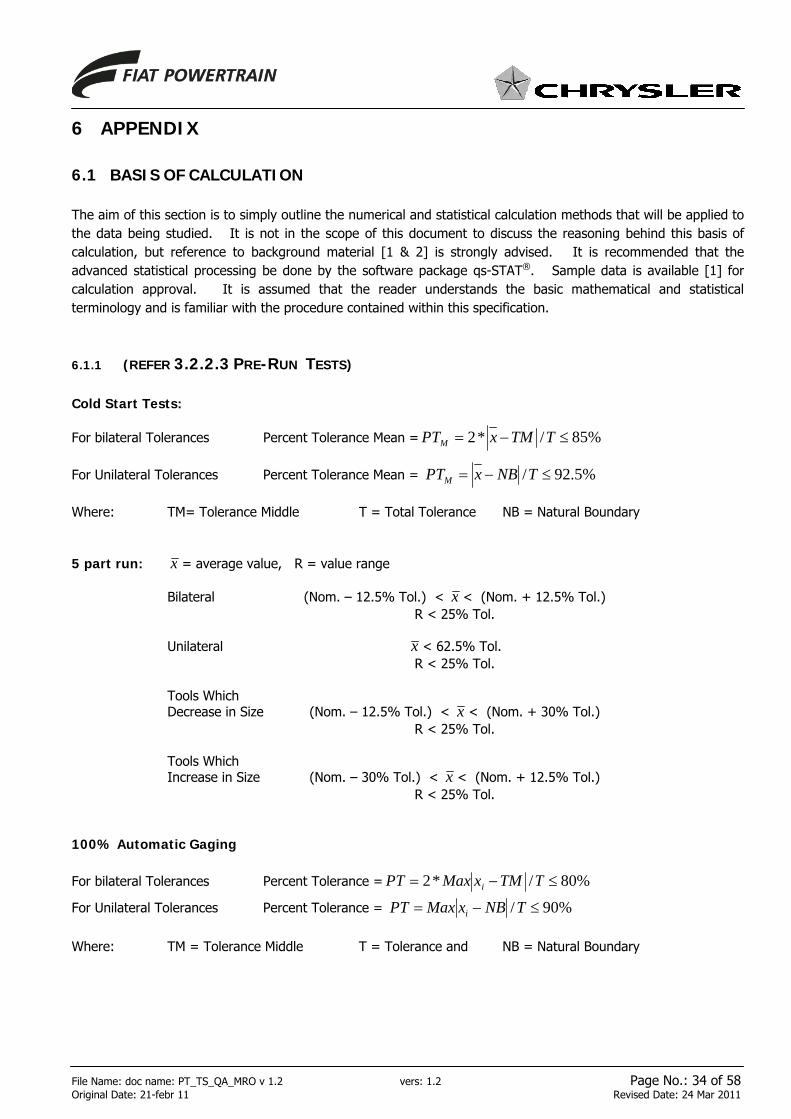
File Name: doc name: PT_TS_QA_MRO v 1.2 vers: 1.2 Page No.: 34 of 58 Original Date: 21-febr 11 Revised Date: 24 Mar 2011
6 APPENDIX
6.1 BASIS OF CALCULATION
The aim of this section is to simply outline the numerical and statistical calculation methods that will be applied to the data being studied. It is not in the scope of this document to discuss the reasoning behind this basis of calculation, but reference to background material [1 & 2] is strongly advised. It is recommended that the advanced statistical processing be done by the software package qs-STAT®. Sample data is available [1] for calculation approval. It is assumed that the reader understands the basic mathematical and statistical terminology and is familiar with the procedure contained within this specification.
6.1.1 (REFER 3.2.2.3 PRE-RUN TESTS)
Cold Start Tests:
For bilateral Tolerances Percent Tolerance Mean = %85/*2 ≤−= TTMxPTM For Unilateral Tolerances Percent Tolerance Mean = %5.92/ ≤−= TNBxPTM Where: TM= Tolerance Middle T = Total Tolerance NB = Natural Boundary 5 part run: x = average value, R = value range Bilateral (Nom. – 12.5% Tol.) < x < (Nom. + 12.5% Tol.) R < 25% Tol. Unilateral x < 62.5% Tol. R < 25% Tol. Tools Which Decrease in Size (Nom. – 12.5% Tol.) < x < (Nom. + 30% Tol.) R < 25% Tol. Tools Which Increase in Size (Nom. – 30% Tol.) < x < (Nom. + 12.5% Tol.) R < 25% Tol. 100% Automatic Gaging For bilateral Tolerances Percent Tolerance = %80/*2 ≤−= TTMxMaxPT i
For Unilateral Tolerances Percent Tolerance = %90/ ≤−= TNBxMaxPT i
Where: TM = Tolerance Middle T = Tolerance and NB = Natural Boundary

File Name: doc name: PT_TS_QA_MRO v 1.2 vers: 1.2 Page No.: 35 of 58 Original Date: 21-febr 11 Revised Date: 24 Mar 2011
6.1.2 PROCESS CAPABILITY The capability indices Pp/Ppk are also calculated using the percentile method (0.135% - x - 99.865%). Bilateral Pp = Tolerance / (Up3 – Lp3) Ppk = Min {(UTL – x )/ (Up3 – x ); ( x – LTL) / ( x – Lp3)} Unilateral Ppk = (UTL – x )/ (Up3 – x ) The type of control chart used depends on the distribution of the data and an ANOVA study of within subgroup versus subgroup-to-subgroup variation. The preferred generic chart type is the location and deviation ( x s) chart. Normal distribution Shewhart chart Selected non-normal distribution Pearson chart Mixed Distribution Extended Shewhart chart Estimators for control charting are: Process average µ1 = x
Estimated deviation σ1 = s2
6.1.3 STABILITY The stability criteria used is that recommended by Q-DAS, referred to as level 2 If instability is present, the indices can still be calculated. To demonstrate the significance of this (or act as a warning to those using the index as the only acceptance criteria) the index call-outs are changed to Tp/Tpk. For a more detailed explanation of the stability criteria please refer to the background text [1 & 2].
6.1.4 SHEWHART CHART WITH EXTENDED LIMITS For more detail explanation of the Shewhart chart with extended limits, please refer to the background text [1 & 2]. Thus, the extended control limits are calculated by the following formula [1]:
UCL = x + (A3 * s + 1.5* σ̂ A)
LCL = x - (A3 * s + 1.5* σ̂ A) where σA is the standard deviation between the random samples according to ANOVA model II [1]. The extension of the limits is controlled by the factor 1.5. This factor has proved successful by experience. If σ̂
A cannot be ascertained by a computer system, the difference between the maximum and the minimum mean values ( x max - x min) has to be applied instead of “1.5* σ̂ A“ to extend the limits. As described under “Process mean values constant“, the process stability has to be judged analogously and subsequently the capability indices have to be determined.

File Name: doc name: PT_TS_QA_MRO v 1.2 vers: 1.2 Page No.: 36 of 58 Original Date: 21-febr 11 Revised Date: 24 Mar 2011
A * s3xi max
xi min
A * s3LCL
UCL
"Extension of the control limits"
Distribution of mean values with σ̂ A from ANOVA, computer based or manually by x imax and x imin

File Name: doc name: PT_TS_QA_MRO v 1.2 vers: 1.2 Page No.: 37 of 58 Original Date: 21-febr 11 Revised Date: 24 Mar 2011
6.2 EVALUATION OF POSITIONAL TOLERANCES
6.2.1 TOLERANCE ZONE Geometric Dimensioning and Tollerancing (GD&T) often provides situations that create bonus tolerances. For the purpose of the evaluation, the additional position provided by Bonus Tolerance shall not be used. This bonus exists on features that are dimensioned as Maximum Material Condition (MMC). These features shall be evaluated as Regardless of Feature Size (RFS). Depending on the assigned tolerances of the measurement coordinates, the tolerance zone for a true position feature is an ellipse (Figure 4.1.1). The shape of the ellipse depends on the scaling of the axes and the specification limits. As a special case, when tolerances and axis scaling are equal, the zone will be a circle. The consideration of the true position tolerance as a rectangle is not allowed because of the extra tolerance area around the corner points that may allow values to be accepted erroneously. This may lead to problems during later manufacturing steps. This means that values outside the circular area (Figure 4.1.1) are to be regarded as outside tolerance.
Figure 4.1.1: Circle versus square tolerance zones Figure 4.1.2: True position values
6.2.2 STUDYING POSITIONAL TOLERANCES USING THE TRUE POSITION VALUE
The definition of true position can be thought of as – “The minimum diameter circle, centered on the theoretically exact location that will encompass the point”. If analysis is done using the true position value (this is a scalar quantity) then we get the situation where two measurements can give the same true position but actually are at a different location (Figure 4.1.2). This means we lose vector information when using true position values. This loss of information can lead to problems rationalizing the evaluation of such processes.
value outsidetolerance
actual tolerance zone
X
Y
+0.125-0.125
-0.125
+0.125
x1
y1
y2
x2

File Name: doc name: PT_TS_QA_MRO v 1.2 vers: 1.2 Page No.: 38 of 58 Original Date: 21-febr 11 Revised Date: 24 Mar 2011
6.2.3 POSITIONAL CAPABILITY USING DATA WITHOUT REFERENCE TO CORRELATION If a capability study of the axis components of the positional feature is done treating each axis individually a problem (figure 4.1.3) can occur.
Figure 4.1.3: Problem of studying axes independently If we study a 2-dimensional process by using two 1-dimensional data sets, we lose correlation (relationship) information. (In a 2-d process, there will always be some correlation.) With reference to Figure 4.1.3, two instances of data scatter patterns have been superimposed. Each of these scatter patterns looks the same from the point of view of the individual axes. Obviously, one instance indicates parts out of specification. This situation is unacceptable for predicting process capability effectively.
6.2.4 PO/POK CAPABILITY INDICES In order to solve this problem capability indices that reflected the 2-dimensional distribution pattern (Figure 4.1.4) have been created by Q-DAS [2]. The index “o” was selected to mark the ‘Position Tolerance’.
Figure 4.1.4: 2-Dimensional distribution
X
Y
+0.125
+0.125
values outsidetolerance

File Name: doc name: PT_TS_QA_MRO v 1.2 vers: 1.2 Page No.: 39 of 58 Original Date: 21-febr 11 Revised Date: 24 Mar 2011
6.2.4.1 PROCESS POTENTIAL INDEX, PO
In order to determine the elliptical random spread region and thus the capability, the center point of the distribution ellipse is laid over the tolerance center point (Figure 6.2.4.2). Consider this expanding so it is just touching the tolerance ellipse. The ratio between these ellipses is used an approximation of Po.
6.2.4.2 PROCESS CAPABILITY INDEX, POK
In order to determine the capability consider the elliptical random spread region again expanding, this time without an offset to tolerance average, so it is just touching the tolerance ellipse (Figure 6.2.4.2). This ratio between these ellipses is an approximation of Pok.
Figure 6.2.4.2: Determination of positional capability indices The probability ellipse indicates the region in “tolerance space” that 99.8% of the values are expected to lie (equivalent to ± 3σ).
Po = B/A
Pok = C/A
Probability ellipse (+/- 3
sigma)
Note: These formulas are for visualization of the indices only. They provide an approximation of the indices. For technical explanation see 5.3- [2].
B
C
A

File Name: doc name: PT_TS_QA_MRO v 1.2 vers: 1.2 Page No.: 40 of 58 Original Date: 21-febr 11 Revised Date: 24 Mar 2011
6.3 CONFIGURATION OF EVALUATION
6.3.1 PROCESS CAPABILITY
6.3.1.1 THE FOLLOWING IS THE CONFIGURATION OF EVALUATION FOR VERSION 10.X IN QS-STAT®
VERSION ME2.0 FOR PROCESS CAPABILITY
12
3
4
1.1

File Name: doc name: PT_TS_QA_MRO v 1.2 vers: 1.2 Page No.: 41 of 58 Original Date: 21-febr 11 Revised Date: 24 Mar 2011
1.2
1.3

File Name: doc name: PT_TS_QA_MRO v 1.2 vers: 1.2 Page No.: 42 of 58 Original Date: 21-febr 11 Revised Date: 24 Mar 2011
2.1
2.2
2.3

File Name: doc name: PT_TS_QA_MRO v 1.2 vers: 1.2 Page No.: 43 of 58 Original Date: 21-febr 11 Revised Date: 24 Mar 2011
3.2
3.1

File Name: doc name: PT_TS_QA_MRO v 1.2 vers: 1.2 Page No.: 44 of 58 Original Date: 21-febr 11 Revised Date: 24 Mar 2011
3.3
3.4

File Name: doc name: PT_TS_QA_MRO v 1.2 vers: 1.2 Page No.: 45 of 58 Original Date: 21-febr 11 Revised Date: 24 Mar 2011
4.1 4.2
4.3 4.4

File Name: doc name: PT_TS_QA_MRO v 1.2 vers: 1.2 Page No.: 46 of 58 Original Date: 21-febr 11 Revised Date: 24 Mar 2011
5
6 7
8
5.1
6.1 6.2
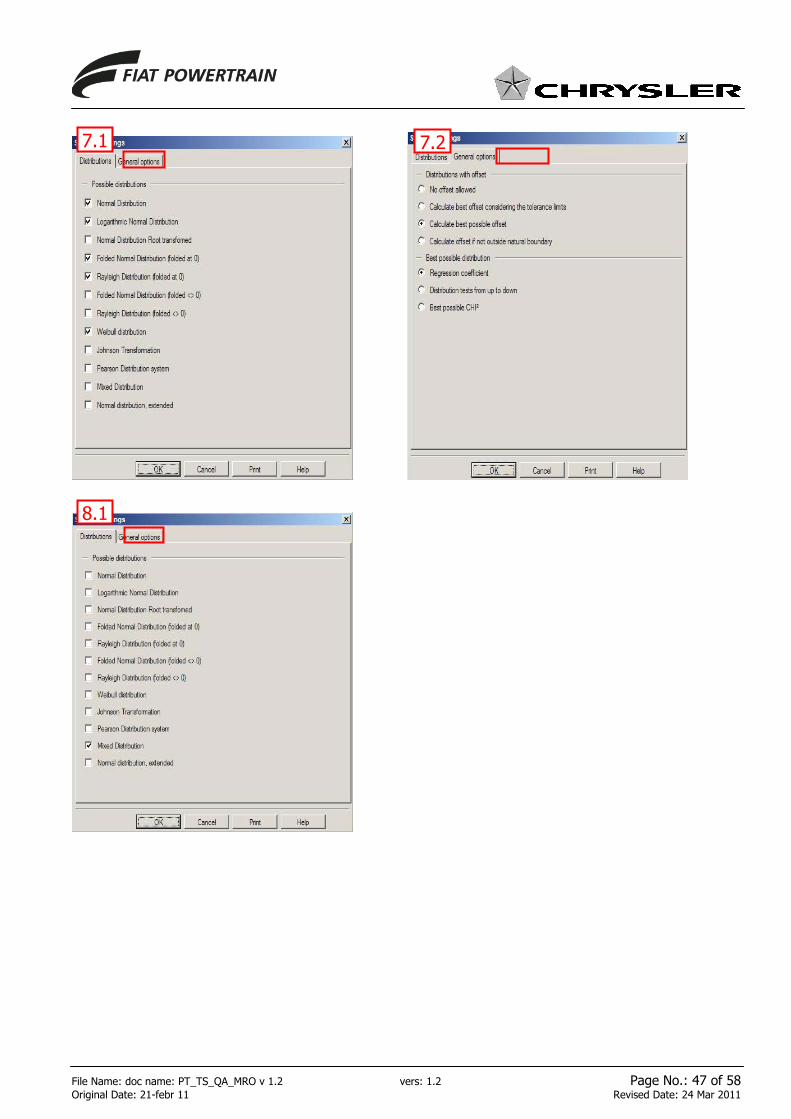
File Name: doc name: PT_TS_QA_MRO v 1.2 vers: 1.2 Page No.: 47 of 58 Original Date: 21-febr 11 Revised Date: 24 Mar 2011
7.1 7.2
8.1
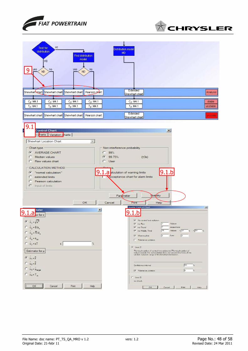
File Name: doc name: PT_TS_QA_MRO v 1.2 vers: 1.2 Page No.: 48 of 58 Original Date: 21-febr 11 Revised Date: 24 Mar 2011
9
9.1
9.1.a
9.1.a
9.1.b
9.1.b

File Name: doc name: PT_TS_QA_MRO v 1.2 vers: 1.2 Page No.: 49 of 58 Original Date: 21-febr 11 Revised Date: 24 Mar 2011
9.2.a 9.2.b
9.2.a
9.2.b
9.2

File Name: doc name: PT_TS_QA_MRO v 1.2 vers: 1.2 Page No.: 50 of 58 Original Date: 21-febr 11 Revised Date: 24 Mar 2011
1011
9.1.a 9.1.b
10.1

File Name: doc name: PT_TS_QA_MRO v 1.2 vers: 1.2 Page No.: 51 of 58 Original Date: 21-febr 11 Revised Date: 24 Mar 2011
10.2
9.2.a
11.1
11.2
11.29.2
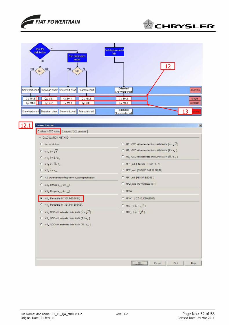
File Name: doc name: PT_TS_QA_MRO v 1.2 vers: 1.2 Page No.: 52 of 58 Original Date: 21-febr 11 Revised Date: 24 Mar 2011
12
12.1
13

File Name: doc name: PT_TS_QA_MRO v 1.2 vers: 1.2 Page No.: 53 of 58 Original Date: 21-febr 11 Revised Date: 24 Mar 2011
13.1

File Name: doc name: PT_TS_QA_MRO v 1.2 vers: 1.2 Page No.: 54 of 58 Original Date: 21-febr 11 Revised Date: 24 Mar 2011
6.3.2 SAMPLE ANALYSIS
6.3.2.1 THE FOLLOWING IS THE CONFIGURATION OF EVALUATION FOR VERSION 10.X IN QS-STAT®
VERSION ME2.0 FOR SAMPLE ANALYSIS
4
3
Ref. 1
1
2
5
1

File Name: doc name: PT_TS_QA_MRO v 1.2 vers: 1.2 Page No.: 55 of 58 Original Date: 21-febr 11 Revised Date: 24 Mar 2011
2.1
2.42.3
2.2

File Name: doc name: PT_TS_QA_MRO v 1.2 vers: 1.2 Page No.: 56 of 58 Original Date: 21-febr 11 Revised Date: 24 Mar 2011
3
4.1

File Name: doc name: PT_TS_QA_MRO v 1.2 vers: 1.2 Page No.: 57 of 58 Original Date: 21-febr 11 Revised Date: 24 Mar 2011
4.2
4.3

File Name: doc name: PT_TS_QA_MRO v 1.2 vers: 1.2 Page No.: 58 of 58 Original Date: 21-febr 11 Revised Date: 24 Mar 2011
5.2
5.1