research and special programs admin., dot … · research and special programs admin., dot...
TRANSCRIPT

875
Research and Special Programs Admin., DOT § 178.318–2
with the reclosing devices as specified in paragraphs (e)(4)(ii) and (e)(4)(iii) of this section.
(3) Pressure relief devices must be de-signed to prevent the entry of foreign matter, the leakage of gas and the de-velopment of any dangerous excess pressure.
(4) Capacity and setting of pressure re-lief devices. (i) In the case of the loss of vacuum in a vacuum-insulated tank or of loss of 20% of the insulation of a portable tank insulated with solid ma-terials, the combined capacity of all pressure relief devices installed must be sufficient so that the pressure (in-cluding accumulation) inside the shell does not exceed 120% of the MAWP.
(ii) For non-flammable refrigerated liquefied gases (except oxygen) and hy-drogen, this capacity may be achieved by the use of frangible discs in parallel with the required safety-relief devices. Frangible discs must rupture at nomi-nal pressure equal to the test pressure of the shell.
(iii) Under the circumstances de-scribed in paragraphs (e)(4)(i) and (e)(4)(ii) of this section, together with complete fire engulfment, the com-bined capacity of all pressure relief de-vices installed must be sufficient to limit the pressure in the shell to the test pressure.
(iv) The required capacity of the re-lief devices must be calculated in ac-cordance with CGA Pamphlet S–1.2 (see § 171.7 of this subchapter).
[66 FR 33450, June 21, 2001]
Subpart I [Reserved]
Subpart J—Specifications for Con-tainers for Motor Vehicle Transportation
SOURCE: 29 FR 18975, Dec. 29, 1964, unless otherwise noted. Redesignated at 32 FR 5606, Apr. 5, 1967.
§ 178.318 Specification MC 201; con-tainer for detonators and percus-sion caps.
§ 178.318–1 Scope. (a) This specification pertains to a
container to be used for the transpor-tation of detonators and percussion
caps in connection with the transpor-tation of liquid nitroglycerin, desen-sitized liquid nitroglycerin or diethylene glycol dinitrate, where any or all of such types of caps may be used for the detonation of liquid nitroglyc-erin, desentitized liquid nitroglycerin or diethylene glycol dinitrate in blast-ing operations. This specification is not intended to take the place of any shipping or packing requirements of this Department where the caps in question are themselves articles of commerce.
(b) [Reserved]
[29 FR 18975, Dec. 29, 1964. Redesignated at 32 FR 5606, Apr. 5, 1967, and amended by Amdt. 178–60, 44 FR 70733, Dec. 10, 1979]
§ 178.318–2 Container. (a) Every container for detonators
and percussion caps coming within the scope of this specification shall be con-structed entirely of hard rubber, phenolresinous or other resinous mate-rial, or other nonmetallic, nonsparking material, except that metal parts may be used in such locations as not in any event to come in contact with any of the caps. Space shall be provided so that each detonator of whatever nature may be inserted in an individual cell in the body of the container, into which each such cap shall snugly fit. There shall be provided no more than twenty (20) such cellular spaces. Space may be provided into which a plurality of per-cussion caps may be carried, provided that such space may be closed with a screw cap, and further provided that each or any such space is entirely sepa-rate from any space provided for any detonator. Each cellular space into which a detonator is to be inserted and carried shall be capable of being cov-ered by a rotary cover so arranged as to expose not more than one cell at any time, and capable of rotation to such a place that all cells will be covered at the same time, at which place means shall be provided to lock the cover in place. Means shall be provided to lock in place the cover for the cells provided for the carrying of detonators. The re-quirement that not more than one cell be exposed at one time need not apply in the case of detonators, although spaces for such caps and detonators shall be separate. Sufficient annular
VerDate Dec<13>2002 10:29 Jan 09, 2003 Jkt 197201 PO 00000 Frm 00875 Fmt 8010 Sfmt 8010 Y:\SGML\197201T.XXX 197201T

876
49 CFR Ch. I (10–1–02 Edition)§ 178.318–2
space shall be provided inside the cover for such detonators that, when the cover is closed, there will be sufficient space to accommodate the wires cus-tomarily attached to such caps. If the material is of such a nature as to re-quire treatment to prevent the absorp-tion of moisture, such treatment shall be applied as shall be necessary in order to provide against the penetra-tion of water by permeation. A suitable
carrying handle shall be provided, ex-cept for which handle no part of the container may project beyond the exte-rior of the body.
(b) Exhibited in plates I and II are line drawings of a container for deto-nators and percussion caps, illustrative of the requirements set forth in § 178.318–2(a). These plates shall not be construed as a part of this specifica-tion.
[29 FR 18975, Dec. 29, 1964. Redesignated at 32 FR 5606, Apr. 5, 1967, and amended by Amdt. 178–60, 44 FR 70733, Dec. 10, 1979]
VerDate Dec<13>2002 10:29 Jan 09, 2003 Jkt 197201 PO 00000 Frm 00876 Fmt 8010 Sfmt 8006 Y:\SGML\197201T.XXX 197201T EC
02M
R91
.076
</G
PH
>

877
Research and Special Programs Admin., DOT § 178.337–1
§ 178.318–3 Marking. Each container must be marked as
prescribed in § 178.2(b).
[Amdt. 178–40, 41 FR 38181, Sept. 9, 1976, as amended at 66 FR 45185, Aug. 28, 2001]
§ 178.320 General requirements appli-cable to all DOT specification cargo tank motor vehicles.
(a) Definitions. For the purposes of this subpart,
Cargo tank, as defined in § 171.8 of this subchapter, means a bulk packaging which:
(1) Is a tank intended primarily for the carriage of liquids or gases (includ-ing appurtenances, reinforcements, fit-tings, and closures). (For definition of ‘‘tank’’, see § 178.345–1(c), § 178.337–1, or § 178.338–1, as applicable);
(2) Is permanently attached to or forms a part of a motor vehicle but which, by reason of its size, construc-tion or attachment to a motor vehicle is loaded or unloaded without being re-moved from the motor vehicle; and
(3) Is not fabricated under a speci-fication for cylinders, portable tanks, tank cars, or multi-unit tank car tanks.
Cargo tank motor vehicle, as defined in § 171.8 of this subchapter, means a motor vehicle with one or more cargo tanks permanently attached to or forming an integral part of the motor vehicle.
Cargo tank wall means those parts of the cargo tank which make up the pri-mary lading retention structure in-cluding shell, bulkheads, and fittings which, when closed during transpor-tation of lading, yields the minimum volume of the cargo tank assembly.
Design type means one or more cargo tanks which are made—
(1) To the same specification; (2) By the same manufacturer; (3) To the same engineering drawings
and calculations, except for minor variations in piping which do not affect the lading retention capability of the cargo tank;
(4) Of the same materials of construc-tion;
(5) To the same cross-sectional di-mensions;
(6) To a length varying by no more than five percent;
(7) With the volume varying by no more than five percent (due to a change in length only); and
(8) For the purposes of § 178.338 only, with the same insulation system.
Manufacturer means any person en-gaged in the manufacture of a DOT specification cargo tank, cargo tank motor vehicle or cargo tank equipment which forms part of the cargo tank wall. This term includes attaching a cargo tank to a motor vehicle or to a motor vehicle suspension component which involves welding on the cargo tank wall. A manufacturer shall reg-ister with the Department in accord-ance with subpart F of part 107 in sub-chapter A of this chapter.
(b) Design certification. (1) Each cargo tank design type shall be certified in conformance with the specification re-quirements by a Design Certifying En-gineer registered in accordance with subpart F of part 107.
(2) The Design Certifying Engineer shall furnish to the manufacturer a certificate to indicate compliance with the specification requirements. The certificate must include the sketches, drawings, and calculations used for cer-tification. Each certificate, including sketches, drawings, and calculations, shall be signed by the Design Certi-fying Engineer.
(3) The manufacturer shall retain the design certificate at his principal place of business for as long as he manufac-tures DOT specification cargo tanks.
(c) Exceptions to the ASME Code. Un-less otherwise specified, when excep-tions are provided in this subpart from compliance with certain paragraphs of the ASME Code, compliance with those paragraphs is not prohibited.
[Amdt. 178–89, 55 FR 37055, Sept. 7, 1990, as amended by Amdt. 178–98, 58 FR 33306, June 16, 1993; Amdt. 178–118, 61 FR 51339, Oct. 1, 1996]
§ 178.337 Specification MC 331; cargo tank motor vehicle primarily for transportation of compressed gases as defined in subpart G of part 173 of this subchapter.
§ 178.337–1 General requirements. (a) ASME Code construction. Tanks
must be— (1) Seamless or welded construction,
or a combination of both;
VerDate Dec<13>2002 10:29 Jan 09, 2003 Jkt 197201 PO 00000 Frm 00877 Fmt 8010 Sfmt 8010 Y:\SGML\197201T.XXX 197201T

878
49 CFR Ch. I (10–1–02 Edition)§ 178.337–1
(2) Designed and constructed in ac-cordance with the ASME Code;
(3) Made of steel or aluminum; how-ever, if aluminum is used, the cargo tank must be insulated and the haz-ardous material to be transported must be compatible with the aluminum (see §§ 178.337–1(e)(2), 173.315(a) table, and 178.337–2(a)(1) of this subchapter); and
(4) Covered with a steel jacket if the cargo tank is insulated and used to transport a flammable gas (see § 173.315(a) table Note 11 of this sub-chapter).
(b) Design pressure. The design pres-sure of a cargo tank authorized under this specification shall be not less than the vapor pressure of the commodity contained therein at 115 °F. or as pre-scribed for a particular commodity in § 173.315(a) of this subchapter, except that in no case shall the design pres-sure of any cargo tank be less than 100 p.s.i.g. nor more than 500 p.s.i.g.
NOTE 1: The term design pressure as used in this specification, is identical to the term MAWP as used in the ASME Code.
(c) Openings. (1) Excess pressure relief valves shall be located in the top of the cargo tank or heads.
(2) A chlorine cargo tank shall have only one opening. That opening shall be in the top of the cargo tank and shall be fitted with a nozzle that meets the following requirements:
(i) On a cargo tank manufactured on or before December 31, 1974, the nozzle shall be protected by a dome cover plate which conforms to either the standard of The Chlorine Institute, Inc., Dwg. 103–3, dated January 23, 1958, or to the standard specified in para-graph (c) (2) (ii) of this section.
(ii) On a cargo tank manufactured on or after January 1, 1975, the nozzle shall be protected by a manway cover which conforms to the standard of The Chlorine Institute, Inc., Dwg. 103–4, dated September 1, 1971.
(d) Reflective design. Every uninsulated cargo tank permanently attached to a cargo tank motor vehicle shall, unless covered with a jacket made of aluminum, stainless steel, or other bright nontarnishing metal, be painted a white, aluminum or similar reflecting color on the upper two-thirds of area of the cargo tank.
(e) Insulation. (1) Each cargo tank re-quired to be insulated must conform with the use and performance require-ments contained in §§ 173.315(a) table and 178.337–1 (a)(3) and (e)(2) of this subchapter.
(2) Each cargo tank intended for chlorine; carbon dioxide, refrigerated liquid; or nitrous oxide, refrigerated liquid service must have suitable insu-lation of such thickness that the over-all thermal conductance is not more than 0.08 Btu per square foot per °F dif-ferential per hour. The conductance must be determined at 60 °F. Insulation material used on cargo tanks for ni-trous oxide, refrigerated liquid must be noncombustible. Insulating material used on cargo tanks for chlorine must be corkboard or polyurethane foam, with a minimum thickness of 4 inches, or 2 inches minimum thickness of ce-ramic fiber/fiberglass of 4 pounds per cubic foot minimum density covered by 2 inches minimum thickness of fiber.
(f) Postweld heat treatment. Postweld heat treatment must be as prescribed in the ASME Code except that each cargo tank constructed in accordance with Part UHT of the ASME Code must be postweld heat treated. Each chlorine cargo tank must be fully radiographed and postweld heat treated in accord-ance with the provisions of the ASME Code under which it is constructed. Where postweld heat treatment is re-quired, the cargo tank must be treated as a unit after completion of all the welds in and/or to the shells and heads. The method must be as prescribed in the ASME Code. Welded attachments to pads may be made after postweld heat treatment. A cargo tank used for anhydrous ammonia must be postweld heat treated. The postweld heat treat-ment must be as prescribed in the ASME Code, but in no event at less than 1050 °F. cargo tank metal tem-perature.
(g) Definitions. The following defini-tions apply to §§ 178.337–1 through 178.337–18:
Emergency discharge control means the ability to stop a cargo tank unloading operation in the event of an uninten-tional release. Emergency discharge control can utilize passive or off-truck remote means to stop the unloading
VerDate Dec<13>2002 10:29 Jan 09, 2003 Jkt 197201 PO 00000 Frm 00878 Fmt 8010 Sfmt 8010 Y:\SGML\197201T.XXX 197201T

879
Research and Special Programs Admin., DOT § 178.337–2
operation. A passive means of emer-gency discharge control automatically shuts off the flow of product without the need for human intervention with-in 20 seconds of an unintentional re-lease caused by a complete separation of the liquid delivery hose. An off-truck remote means of emergency dis-charge control permits a qualified per-son attending the unloading operation to close the cargo tank’s internal self-closing stop valve and shut off all mo-tive and auxiliary power equipment at a distance from the cargo tank motor vehicle.
Excess flow valve, integral excess flow valve, or excess flow feature means a component that will close automati-cally if the flow rate of a gas or liquid through the component reaches or ex-ceeds the rated flow of gas or liquid specified by the original valve manu-facturer when piping mounted directly on the valve is sheared off before the first valve, pump, or fitting down-stream from the valve.
Internal self-closing stop valve means a primary shut off valve installed in a product discharge outlet of a cargo tank and designed to be kept closed by self-stored energy.
Primary discharge control system means a primary shut-off installed at a product discharge outlet of a cargo tank consisting of an internal self-clos-ing stop valve that may include an in-tegral excess flow valve or an excess flow feature, together with linkages that must be installed between the valve and remote actuator to provide manual and thermal on-truck remote means of closure.
[Order 59–B, 30 FR 579, Jan. 16, 1965. Redesig-nated at 32 FR 5606, Apr. 5, 1967]
EDITORIAL NOTE: For FEDERAL REGISTER ci-tations affecting § 178.337–1, see the List of CFR Sections Affected which appears in the Finding Aids section of the printed volume and on GPO Access.
§ 178.337–2 Material.
(a) General. (1) All material used for construction of the cargo tank and ap-purtenances must be suitable for use with the commodities to be trans-ported therein and must conform to the requirements of the ASME Code and/or requirements of the American
Society for Testing and Materials in all respects.
(2) Impact tests are required on steel used in the fabrication of each cargo tank constructed in accordance with part UHT of the ASME Code. The tests must be made on a lot basis. A lot is defined as 100 tons or less of the same heat treatment processing lot having a thickness variation no greater than plus or minus 25 percent. The minimum impact required for full size specimens must be 20 foot-pounds in the longitu-dinal direction at ¥30 °F., Charpy V-Notch and 15 foot-pounds in the trans-verse direction at ¥30 °F., Charpy V-Notch. The required values for subsize specimens must be reduced in direct proportion to the cross-sectional area of the specimen beneath the notch. If a lot does not meet this requirement, in-dividual plates may be accepted if they individually meet this requirement.
(3) The fabricator shall record the heat, and slab numbers, and the cer-tified Charpy impact values, where re-quired, of each plate used in each cargo tank on a sketch showing the location of each plate in the shell and heads of the cargo tank. Copies of each sketch shall be provided to the owner and re-tained for at least five years by the fabricator and made available to duly identified representatives of the De-partment of Transportation.
(4) The direction of final rolling of the shell material shall be the circum-ferential orientation of the cargo tank shell.
(b) For a chlorine cargo tank. Plates, the manway nozzle, and anchorage shall be made of carbon steel which meets the following requirements:
(1) For a cargo tank manufactured on or before December 31, 1974—
(i) Material shall conform to ASTM Specification A–300 –58, titled ‘‘Steel Plates for Pressure Vessels for Service at Low Temperatures’’;
(ii) Material shall be Class 1, Grade A, flange or firebox quality;
(iii) Plate impact test specimens, as required under paragraph (a) of this section, shall be of the Charpy keyhole notch type; and
(iv) Plate impact test specimens shall meet the impact test require-ments in paragraph (a) of this section in both the longitudinal and transverse
VerDate Dec<13>2002 10:29 Jan 09, 2003 Jkt 197201 PO 00000 Frm 00879 Fmt 8010 Sfmt 8010 Y:\SGML\197201T.XXX 197201T

880
49 CFR Ch. I (10–1–02 Edition)§ 178.337–3
directions of rolling at a temperature of minus 45.5 C. (¥50 °F.).
(2) For a cargo tank manufactured on or after January 1, 1975—
(i) Material shall conform to ASTM Specification A–612–72a, Grade B or A 516, Grade 65 or 70;
(ii) Material shall meet the Charpy V-notch test requirements of ASTM Specification A 20; and
(iii) Plate impact test specimens shall meet the impact test require-ments in paragraph (a) of this section in both the longitudinal and transverse directions of rolling at a temperature of minus 40 °C. (¥40 °F.).
(c) A cargo tank in anhydrous ammo-nia service must be constructed of steel. The use of copper, silver, zinc or their alloys is prohibited. Baffles made from aluminum may be used only if joined to the cargo tank by a process not requiring postweld heat treatment of the cargo tank.
[Order 59–B, 30 FR 579, Jan. 16, 1965. Redesig-nated at 32 FR 5606, Apr. 5, 1967]
EDITORIAL NOTE: For FEDERAL REGISTER ci-tations affecting § 178.337–2, see the List of CFR Sections Affected which appears in the Finding Aids section of the printed volume and on GPO Access.
§ 178.337–3 Structural integrity. (a) General requirements and accept-
ance criteria. (1) Except as provided in paragraph (d) of this section, the max-imum calculated design stress at any point in the cargo tank may not exceed the maximum allowable stress value prescribed in Section VIII of the ASME Code, or 25 percent of the tensile strength of the material used.
(2) The relevant physical properties of the materials used in each cargo tank may be established either by a certified test report from the material manufacturer or by testing in conform-ance with a recognized national stand-ard. In either case, the ultimate tensile strength of the material used in the de-sign may not exceed 120 percent of the ultimate tensile strength specified in either the ASME Code or the ASTM standard to which the material is man-ufactured.
(3) The maximum design stress at any point in the cargo tank must be calculated separately for the loading conditions described in paragraphs (b),
(c), and (d) of this section. Alternate test or analytical methods, or a com-bination thereof, may be used in place of the procedures described in para-graphs (b), (c), and (d) of this section, if the methods are accurate and verifiable.
(4) Corrosion allowance material may not be included to satisfy any of the design calculation requirements of this section.
(b) The static design and construc-tion of each cargo tank must be in ac-cordance with section VIII of the ASME Code. The cargo tank design must include calculation of stresses generated by design pressure, the weight of lading, the weight of struc-ture supported by the cargo tank wall, and the effect of temperature gradients resulting from lading and ambient temperature extremes. When dissimilar materials are used, their thermal coef-ficients must be used in calculation of thermal stresses. Stress concentrations in tension, bending and torsion which occur at pads, cradles, or other sup-ports must be considered in accordance with appendix G of the ASME Code.
(c) Shell design. Shell stresses result-ing from static or dynamic loadings, or combinations thereof, are not uniform throughout the cargo tank motor vehi-cle. The vertical, longitudinal, and lat-eral normal operating loadings can occur simultaneously and must be combined. The vertical, longitudinal and lateral extreme dynamic loadings occur separately and need not be com-bined.
(1) Normal operating loadings. The fol-lowing procedure addresses stress in the tank shell resulting from normal operating loadings. The effective stress (the maximum principal stress at any point) must be determined by the fol-lowing formula:
S = 0.5(Sy + Sx) ± [0.25(Sy ¥ Sx)2 + Ss2]0.5
Where:
(i) S = effective stress at any given point under the combination of static and normal operating loadings that can occur at the same time, in psi.
(ii) Sy = circumferential stress gen-erated by the MAWP and external pres-sure, when applicable, plus static head, in psi.
VerDate Dec<13>2002 10:29 Jan 09, 2003 Jkt 197201 PO 00000 Frm 00880 Fmt 8010 Sfmt 8010 Y:\SGML\197201T.XXX 197201T

881
Research and Special Programs Admin., DOT § 178.337–3
(iii) Sx = The following net longitu-dinal stress generated by the following static and normal operating loading conditions, in psi:
(A) The longitudinal stresses result-ing from the MAWP and external pres-sure, when applicable, plus static head, in combination with the bending stress generated by the static weight of the fully loaded cargo tank motor vehicle, all structural elements, equipment and appurtenances supported by the cargo tank wall;
(B) The tensile or compressive stress resulting from normal operating longi-tudinal acceleration or deceleration. In each case, the forces applied must be 0.35 times the vertical reaction at the suspension assembly, applied at the road surface, and as transmitted to the cargo tank wall through the suspension assembly of a trailer during decelera-tion; or the horizontal pivot of the truck tractor or converter dolly fifth wheel, or the drawbar hinge on the fixed dolly during acceleration; or an-choring and support members of a truck during acceleration and decelera-tion, as applicable. The vertical reac-tion must be calculated based on the static weight of the fully loaded cargo tank motor vehicle, all structural ele-ments, equipment and appurtenances supported by the cargo tank wall. The following loadings must be included:
(1) The axial load generated by a decelerative force;
(2) The bending moment generated by a decelerative force;
(3) The axial load generated by an ac-celerative force; and
(4) The bending moment generated by an accelerative force; and
(C) The tensile or compressive stress generated by the bending moment re-sulting from normal operating vertical accelerative force equal to 0.35 times the vertical reaction at the suspension assembly of a trailer; or the horizontal pivot of the upper coupler (fifth wheel) or turntable; or anchoring and support members of a truck, as applicable. The vertical reaction must be calculated based on the static weight of the fully loaded cargo tank motor vehicle, all structural elements, equipment and ap-purtenances supported by the cargo tank wall.
(iv) Ss = The following shear stresses generated by the following static and normal operating loading conditions, in psi:
(A) The static shear stress resulting from the vertical reaction at the sus-pension assembly of a trailer, and the horizontal pivot of the upper coupler (fifth wheel) or turntable; or anchoring and support members of a truck, as ap-plicable. The vertical reaction must be calculated based on the static weight of the fully loaded cargo tank motor vehicle, all structural elements, equip-ment and appurtenances supported by the cargo tank wall;
(B) The vertical shear stress gen-erated by a normal operating accelera-tive force equal to 0.35 times the vertical reaction at the suspension as-sembly of a trailer; or the horizontal pivot of the upper coupler (fifth wheel) or turntable; or anchoring and support members of a truck, as applicable. The vertical reaction must be calculated based on the static weight of the fully loaded cargo tank motor vehicle, all structural elements, equipment and ap-purtenances supported by the cargo tank wall;
(C) The lateral shear stress generated by a normal operating lateral accelera-tive force equal to 0.2 times the vertical reaction at each suspension as-sembly of a trailer, applied at the road surface, and as transmitted to the cargo tank wall through the suspension assembly of a trailer, and the hori-zontal pivot of the upper coupler (fifth wheel) or turntable; or anchoring and support members of a truck, as applica-ble. The vertical reaction must be cal-culated based on the static weight of the fully loaded cargo tank motor vehi-cle, all structural elements, equipment and appurtenances supported by the cargo tank wall; and
(D) The torsional shear stress gen-erated by the same lateral forces as de-scribed in paragraph (c)(1)(iv)(C) of this section.
(2) Extreme dynamic loadings. The fol-lowing procedure addresses stress in the tank shell resulting from extreme dynamic loadings. The effective stress (the maximum principal stress at any point) must be determined by the fol-lowing formula:
S = 0.5(Sy + Sx) ± [0.25(Sy ¥ Sx)2 + Ss2]0.5
VerDate Dec<13>2002 10:29 Jan 09, 2003 Jkt 197201 PO 00000 Frm 00881 Fmt 8010 Sfmt 8010 Y:\SGML\197201T.XXX 197201T

882
49 CFR Ch. I (10–1–02 Edition)§ 178.337–3
Where:(i) S = effective stress at any given
point under a combination of static and extreme dynamic loadings that can occur at the same time, in psi.
(ii) Sy = circumferential stress gen-erated by MAWP and external pressure, when applicable, plus static head, in psi.
(iii) Sx = the following net longitu-dinal stress generated by the following static and extreme dynamic loading conditions, in psi:
(A) The longitudinal stresses result-ing from the MAWP and external pres-sure, when applicable, plus static head, in combination with the bending stress generated by the static weight of the fully loaded cargo tank motor vehicle, all structural elements, equipment and appurtenances supported by the tank wall;
(B) The tensile or compressive stress resulting from extreme longitudinal acceleration or deceleration. In each case the forces applied must be 0.7 times the vertical reaction at the sus-pension assembly, applied at the road surface, and as transmitted to the cargo tank wall through the suspension assembly of a trailer during decelera-tion; or the horizontal pivot of the truck tractor or converter dolly fifth wheel, or the drawbar hinge on the fixed dolly during acceleration; or the anchoring and support members of a truck during acceleration and decelera-tion, as applicable. The vertical reac-tion must be calculated based on the static weight of the fully loaded cargo tank motor vehicle, all structural ele-ments, equipment and appurtenances supported by the cargo tank wall. The following loadings must be included:
(1) The axial load generated by a decelerative force;
(2) The bending moment generated by a decelerative force;
(3) The axial load generated by an ac-celerative force; and
(4) The bending moment generated by an accelerative force; and
(C) The tensile or compressive stress generated by the bending moment re-sulting from an extreme vertical accel-erative force equal to 0.7 times the vertical reaction at the suspension as-sembly of a trailer, and the horizontal pivot of the upper coupler (fifth wheel)
or turntable; or the anchoring and sup-port members of a truck, as applicable. The vertical reaction must be cal-culated based on the static weight of the fully loaded cargo tank motor vehi-cle, all structural elements, equipment and appurtenances supported by the cargo tank wall.
(iv) Ss = The following shear stresses generated by static and extreme dy-namic loading conditions, in psi:
(A) The static shear stress resulting from the vertical reaction at the sus-pension assembly of a trailer, and the horizontal pivot of the upper coupler (fifth wheel) or turntable; or anchoring and support members of a truck, as ap-plicable. The vertical reaction must be calculated based on the static weight of the fully loaded cargo tank motor vehicle, all structural elements, equip-ment and appurtenances supported by the cargo tank wall;
(B) The vertical shear stress gen-erated by an extreme vertical accelera-tive force equal to 0.7 times the vertical reaction at the suspension as-sembly of a trailer, and the horizontal pivot of the upper coupler (fifth wheel) or turntable; or anchoring and support members of a truck, as applicable. The vertical reaction must be calculated based on the static weight of the fully loaded cargo tank motor vehicle, all structural elements, equipment and ap-purtenances supported by the cargo tank wall;
(C) The lateral shear stress generated by an extreme lateral accelerative force equal to 0.4 times the vertical re-action at the suspension assembly of a trailer, applied at the road surface, and as transmitted to the cargo tank wall through the suspension assembly of a trailer, and the horizontal pivot of the upper coupler (fifth wheel) or turn-table; or anchoring and support mem-bers of a truck, as applicable. The vertical reaction must be calculated based on the static weight of the fully loaded cargo tank motor vehicle, all structural elements, equipment and ap-purtenances supported by the cargo tank wall; and
(D) The torsional shear stress gen-erated by the same lateral forces as de-scribed in paragraph (c)(2)(iv)(C) of this section.
VerDate Dec<13>2002 10:29 Jan 09, 2003 Jkt 197201 PO 00000 Frm 00882 Fmt 8010 Sfmt 8010 Y:\SGML\197201T.XXX 197201T

883
Research and Special Programs Admin., DOT § 178.337–4
(d) In order to account for stresses due to impact in an accident, the de-sign calculations for the cargo tank shell and heads must include the load resulting from the design pressure in combination with the dynamic pres-sure resulting from a longitudinal de-celeration of ‘‘2g’’. For this loading condition the stress value used may not exceed the lesser of the yield strength or 75 percent of the ultimate tensile strength of the material of con-struction. For cargo tanks constructed of stainless steel the maximum design stress may not exceed 75 percent of the ultimate tensile strength of the type steel used.
(e) The minimum metal thickness for the shell and heads must be 4.75 mm (0.187 inch) for steel and 6.86 mm (0.270 inch) for aluminum, except for chlorine and sulfur dioxide tanks. For a cargo tank used in chlorine or sulfur dioxide service, the cargo tank must be made of steel. A corrosion allowance of 20 percent or 2.54 mm (0.10 inch), which-ever is less, must be added to the thickness otherwise required for sulfur dioxide and chlorine tank material. In chlorine cargo tanks, the wall thick-ness must be at least 1.59 cm (0.625 inch), including corrosion allowance.
(f) Where a cargo tank support is at-tached to any part of the cargo tank wall, the stresses imposed on the cargo tank wall must meet the requirements in paragraph (a) of this section.
(g) The design, construction, and in-stallation of an appurtenance to the cargo tank must be such that, in the event of its damage or failure, the lad-ing retention integrity of the cargo tank will not be adversely affected.
(1) A lightweight attachment, such as a conduit clip, brakeline clip or placard holder, must be constructed of a mate-rial of lesser strength than the cargo tank wall material and may not be more than 72 percent of the thickness of the material to which it is attached. The attachment may be secured di-rectly to the cargo tank wall if the de-vice is designed and installed in such a manner that, if damaged, it will not af-fect the lading retention integrity of the cargo tank. The lightweight at-tachment must be secured to the cargo tank wall by continuous weld or in such a manner as to preclude forma-
tion of pockets, which may become sites for incipient corrosion. Attach-ments meeting the requirements of this paragraph are not authorized for cargo tanks constructed under part UHT of the ASME Code.
(2) Except as prescribed in § 178.337–3(g)(1), the welding of any appur-tenance of the cargo tank wall must be made by attachment of a mounting pad, so that there will be no adverse ef-fect upon the lading retention integ-rity of the cargo tank if any force is applied to the appurtenance, from any direction. The thickness of the mount-ing pad may not be less than that of the shell or head to which it is at-tached, and not more than 1.5 times the shell or head thickness. However, a pad with a minimum thickness of 6.35 mm (0.250 inch) may be used when the shell or head thickness is over 6.35 mm (0.250 inch). If weep holes or tell-tale holes are used, the pad must be drilled or punched at its lowest point before it is welded. Each pad must:
(i) Extend at least 5.08 cm (2 inches) in each direction from any point of at-tachment of an appurtenance;
(ii) Have rounded corners, or other-wise be shaped in a manner to mini-mize stress concentrations on the shell or head; and
(iii) Be attached by a continuous weld around the pad, except for a small gap at the lowest point for draining, using filler material conforming to the recommendations of the manufacturer of the head or shell material.
[Amdt. 178–89, 55 FR 37056, Sept. 7, 1990, as amended by Amdt. 178–104, 59 FR 49135, Sept. 26, 1994; Amdt. 178–105, 60 FR 17401, Apr. 5, 1995; Amdt. 178–118, 61 FR 51340, Oct. 1, 1996; 65 FR 58631, Sept. 29, 2000]
§ 178.337–4 Joints.
(a) Joints shall be as required by the ASME Code, with all undercutting in shell and head material repaired as specified therein.
(b) Welding procedure and welder per-formance must be in accordance with Section IX of the ASME Code. In addi-tion to the essential variables named therein, the following must be consid-ered as essential variables: Number of passes; thickness of plate; heat input
VerDate Dec<13>2002 10:29 Jan 09, 2003 Jkt 197201 PO 00000 Frm 00883 Fmt 8010 Sfmt 8010 Y:\SGML\197201T.XXX 197201T

884
49 CFR Ch. I (10–1–02 Edition)§ 178.337–5
per pass; and manufacturer’s identi-fication of rod and flux. When fabrica-tion is done in accordance with part UHT of the ASME Code, filler material containing more than 0.08 percent va-nadium must not be used. The number of passes, thickness of plate, and heat input per pass may not vary more than 25 percent from the procedure or welder qualifications. Records of the qualifica-tions must be retained for at least 5 years by the cargo tank manufacturer and must be made available to duly identified representatives of the De-partment and the owner of the cargo tank.
(c) All longitudinal shell welds shall be located in the upper half of the cargo tank.
(d) Edge preparation of shell and head components may be by machine heat processes, provided such surfaces are remelted in the subsequent welding process. Where there will be no subse-quent remelting of the prepared surface as in a tapered section, the final 0.050 inch of material shall be removed by mechanical means.
(e) The maximum tolerance for mis-alignment and butting up shall be in accordance with the ASME Code.
(f) Substructures shall be properly fitted before attachment, and the weld-ing sequence shall be such as to mini-mize stresses due to shrinkage of welds.
[Order 59–B, 30 FR 580, Jan. 16, 1965. Redesig-nated at 32 FR 5606, Apr. 5, 1967]
EDITORIAL NOTE: For FEDERAL REGISTER ci-tations affecting § 178.337–4, see the List of CFR Sections Affected which appears in the Finding Aids section of the printed volume and on GPO Access.
§ 178.337–5 Bulkheads, baffles and ring stiffeners.
(a) Not a specification requirement. (b) [Reserved]
[Order 59–B, 30 FR 580, Jan. 16, 1965. Redesig-nated at 32 FR 5606, Apr. 5, 1967]
§ 178.337–6 Closure for manhole. (a) Each cargo tank marked or cer-
tified after April 21, 1994, must be pro-vided with a manhole conforming to paragraph UG–46(g)(1) and other appli-cable requirements of the ASME Code, except that a cargo tank constructed of NQT steel having a capacity of 3500
water gallons or less may be provided with an inspection opening conforming to paragraph UG–46 and other applica-ble requirements of the ASME Code in-stead of a manhole.
(b) The manhole assembly of cargo tanks constructed after June 30, 1979, may not be located on the front head of the cargo tank.
[Amdt. 178–7, 34 FR 18250, Nov. 14, 1969, as amended by Amdt. 178–52, 43 FR 58820, Dec. 18, 1978; Amdt. 178–89, 54 FR 25017, June 12, 1989; 55 FR 21038, May 22, 1990; 56 FR 27876, June 17, 1991; 58 FR 12905, March 8, 1993; Amdt. 178–118, 61 FR 51340, Oct. 1, 1996]
§ 178.337–7 Overturn protection.
(a) See § 178.337–10. (b) [Reserved]
[Order 59–B, 30 FR 580, Jan. 16, 1965. Redesig-nated at 32 FR 5606, Apr. 5, 1967]
§ 178.337–8 Openings, inlets, and out-lets.
(a) General. The requirements in this paragraph (a) apply to MC 331 cargo tanks except for those used to trans-port chlorine. The requirements for in-lets and outlets on chlorine cargo tanks are in paragraph (b) of this sec-tion.
(1) An opening must be provided on each cargo tank used for the transpor-tation of liquefied materials to permit complete drainage.
(2) Except for gauging devices, ther-mometer wells, pressure relief valves, manhole openings, product inlet open-ings, and product discharge openings, each opening in a cargo tank must be closed with a plug, cap, or bolted flange.
(3) Except as provided in paragraph (b) of this section, each product inlet opening, including vapor return lines, must be fitted with a back flow check valve or an internal self-closing stop valve located inside the cargo tank or inside a welded nozzle that is an inte-gral part of the cargo tank. The valve seat must be located inside the cargo tank or within 2.54 cm (one inch) of the external face of the welded flange. Damage to parts exterior to the cargo tank or mating flange must not pre-vent effective seating of the valve. All parts of a valve inside a cargo tank or
VerDate Dec<13>2002 10:29 Jan 09, 2003 Jkt 197201 PO 00000 Frm 00884 Fmt 8010 Sfmt 8010 Y:\SGML\197201T.XXX 197201T

885
Research and Special Programs Admin., DOT § 178.337–8
welded flange must be made of mate-rial that will not corrode or deteriorate in the presence of the lading.
(4) Except as provided in paragraphs (a)(5), (b), and (c) of this section, each liquid or vapor discharge outlet must be fitted with a primary discharge con-trol system as defined in § 178.337–1(g). Thermal remote operators must acti-vate at a temperature of 121.11°C (250 °F) or less. Linkages between closures and remote operators must be corro-sion resistant and effective in all types of environmental conditions incident to discharging of product.
(i) On a cargo tank over 13,247.5 L (3,500 gallons) water capacity, thermal and mechanical means of remote clo-sure must be installed at the ends of the cargo tank in at least two diago-nally opposite locations. If the loading/unloading connection at the cargo tank is not in the general vicinity of one of the two locations specified in the first sentence of this paragraph (a)(4)(i), ad-ditional means of thermal remote clo-sure must be installed so that heat from a fire in the loading/unloading connection area or the discharge pump will activate the primary discharge control system. The loading/unloading connection area is where hoses or hose reels are connected to the permanent metal piping.
(ii) On a cargo tank of 13,247.5 L (3,500 gallons) water capacity or less, a ther-mal means of remote closure must be installed at or near the internal self-closing stop valve. A mechanical means of remote closure must be in-stalled on the end of the cargo tank furthest away from the loading/unload-ing connection area. The loading/un-loading connection area is where hoses or hose reels are connected to the per-manent metal piping. Linkages be-tween closures and remote operators must be corrosion resistant and effec-tive in all types of environmental con-ditions incident to discharge of prod-uct.
(iii) All parts of a valve inside a cargo tank or within a welded flange must be made of material that will not corrode or deteriorate in the presence of the lading.
(iv) An excess flow valve, integral ex-cess flow valve, or excess flow feature must close if the flow reaches the rated
flow of a gas or liquid specified by the original valve manufacturer when pip-ing mounted directly on the valve is sheared off before the first valve, pump, or fitting downstream from the excess flow valve, integral excess flow valve, or excess flow feature.
(v) An integral excess flow valve or the excess flow feature of an internal self-closing stop valve may be designed with a bypass, not to exceed 0.1016 cm (0.040 inch) diameter opening, to allow equalization of pressure.
(vi) The internal self-closing stop valve must be designed so that the self-stored energy source and the valve seat are located inside the cargo tank or within 2.54 cm (one inch) of the exter-nal face of the welded flange. Damage to parts exterior to the cargo tank or mating flange must not prevent effec-tive seating of the valve.
(5) A primary discharge control sys-tem is not required on the following:
(i) A vapor or liquid discharge open-ing of less than 11⁄4 NPT equipped with an excess flow valve together with a manually operated external stop valve in place of an internal self-closing stop valve.
(ii) An engine fuel line on a truck-mounted cargo tank of not more than 3⁄4 NPT equipped with a valve having an integral excess flow valve or excess flow feature.
(iii) A cargo tank motor vehicle cer-tified before January 1, 1995, unless in-tended for use to transport a flam-mable liquid, flammable gas, hydrogen chloride, refrigerated liquid, or anhy-drous ammonia.
(6) In addition to the internal self-closing stop valve, each filling and dis-charge line must be fitted with a stop valve located in the line between the internal self-closing stop valve and the hose connection. A back flow check valve or excess flow valve may not be used to satisfy this requirement.
(7) An excess flow valve may be de-signed with a bypass, not to exceed a 0.1016 centimeter (0.040 inch) diameter opening, to allow equalization of pres-sure.
(b) Inlets and discharge outlets on chlo-rine tanks. The inlet and discharge out-lets on a cargo tank used to transport chlorine must meet the requirements of § 178.337–1(c)(2) and must be fitted
VerDate Dec<13>2002 10:29 Jan 09, 2003 Jkt 197201 PO 00000 Frm 00885 Fmt 8010 Sfmt 8010 Y:\SGML\197201T.XXX 197201T

886
49 CFR Ch. I (10–1–02 Edition)§ 178.337–9
with an internal excess flow valve. In addition to the internal excess flow valve, the inlet and discharge outlets must be equipped with an external stop valve (angle valve). Excess flow valves must conform to the standards of The Chlorine Institute, Inc., as follows:
(1) A valve conforming to Drawing 101–7, dated July 1993, must be installed under each liquid angle valve.
(2) A valve conforming to Drawing 106–6, dated July 1993, must be installed under each gas angle valve.
(c) Discharge outlets on carbon dioxide, refrigerated liquid, cargo tanks. A dis-charge outlet on a cargo tank used to transport carbon dioxide, refrigerated liquid is not required to be fitted with an internal self-closing stop valve.
[64 FR 28049, May 24, 1999, as amended at 66 FR 45387, Aug. 28, 2001]
§ 178.337–9 Pressure relief devices, piping, valves, hoses, and fittings.
(a) Pressure relief devices. (1) See § 173.315(i) of this subchapter.
(2) On cargo tanks for carbon dioxide or nitrous oxide see § 173.315 (i) (9) and (10) of this subchapter.
(3) Each valve must be designed, con-structed, and marked for a rated pres-sure not less than the cargo tank de-sign pressure at the temperature ex-pected to be encountered.
(b) Piping, valves, hose, and fittings. (1) The burst pressure of all piping, pipe fittings, hose and other pressure parts, except for pump seals and pressure re-lief devices, must be at least 4 times the design pressure of the cargo tank. Additionally, the burst pressure may not be less than 4 times any higher pressure to which each pipe, pipe fit-ting, hose or other pressure part may be subjected to in service. For chlorine service, see paragraph (b)(7) of this sec-tion.
(2) Pipe joints must be threaded, welded or flanged. If threaded pipe is used, the pipe and fittings must be Schedule 80 weight or heavier. Malle-able metals must be used in the con-struction of valves and fittings. Where copper tubing is permitted, joints shall be brazed or be of equally strong metal union type. The melting point of the brazing material may not be lower than 1000 °F. The method of joining tubing must not reduce the strength of
the tubing, such as by the cutting of threads.
(3) Each hose coupling must be de-signed for a pressure of at least 120 per-cent of the hose design pressure and so that there will be no leakage when con-nected.
(4) Piping must be protected from damage due to thermal expansion and contraction, jarring, and vibration. Slip joints are not authorized for this purpose.
(5) Piping and fittings must be grouped in the smallest practicable space and protected from damage as required by § 178.337–10.
(6) Cargo tank manufacturers and fabricators must demonstrate that all piping, valves, and fittings on a cargo tank are free from leaks. To meet this requirement, the piping, valves, and fittings must be tested after installa-tion at not less than 80 percent of the design pressure marked on the cargo tank.
(7) A hose assembler must: (i) Permanently mark each hose as-
sembly with a unique identification number.
(ii) Demonstrate that each hose as-sembly is free from leaks by per-forming the tests and inspections in § 180.416(f) of this subchapter.
(iii) Mark each hose assembly with the month and year of its original pres-sure test.
(8) Chlorine cargo tanks. Angle valves on cargo tanks intended for chlorine service must conform to Drawing 104–8, dated July 1993, in the standards of The Chlorine Institute. Before installation, each angle valve must be tested for leakage at not less than 225 psig using dry air or inert gas.
(c) Marking inlets and outlets. Except for gauging devices, thermometer wells, and pressure relief valves, each cargo tank inlet and outlet must be marked ‘‘liquid’’ or ‘‘vapor’’ to des-ignate whether it communicates with liquid or vapor when the cargo tank is filled to the maximum permitted fill-ing density. A filling line that commu-nicates with vapor may be marked ‘‘spray-fill’’ instead of ‘‘vapor.’’
(d) Refrigeration and heating coils. (1) Refrigeration and heating coils must be securely anchored with provisions for thermal expansion. The coils must
VerDate Dec<13>2002 10:29 Jan 09, 2003 Jkt 197201 PO 00000 Frm 00886 Fmt 8010 Sfmt 8010 Y:\SGML\197201T.XXX 197201T

887
Research and Special Programs Admin., DOT § 178.337–11
be pressure tested externally to at least the cargo tank test pressure, and internally to either the tank test pres-sure or twice the working pressure of the heating/refrigeration system, whichever is higher. A cargo tank may not be placed in service if any leakage occurs or other evidence of damage is found. The refrigerant or heating me-dium to be circulated through the coils must not be capable of causing any ad-verse chemical reaction with the cargo tank lading in the event of leakage. The unit furnishing refrigeration may be mounted on the motor vehicle.
(2) Where any liquid susceptible to freezing, or the vapor of any such liq-uid, is used for heating or refrigera-tion, the heating or refrigeration sys-tem shall be arranged to permit com-plete drainage.
[Order 59–B, 30 FR 580, Jan. 16, 1965. Redesig-nated at 32 FR 5606, Apr. 5, 1967]
EDITORIAL NOTE: For FEDERAL REGISTER ci-tations affecting § 178.337–9, see the List of CFR Sections Affected which appears in the Finding Aids section of the printed volume and on GPO Access.
178.337–10 Protection of fittings. (a) All valves, fittings, safety relief
devices, and other accessories to the tank proper shall be protected in ac-cordance with paragraph (b) of this sec-tion against such damage as could be caused by collision with other vehicles or objects, jackknifing and over-turning. In addition, safety relief valves shall be so protected that in the event of overturn of the vehicle on to a hard surface, their opening will not be prevented and their discharge will not be restricted.
(b) The protective devices or housing must be designed to withstand static loading in any direction equal to twice the weight of the tank and attach-ments when filled with the lading, using a safety factor of not less than four, based on the ultimate strength of the material to be used, without dam-age to the fittings protected, and must be made of metal at least 3⁄16-inch thick.
(c) For chlorine tanks. There shall be a protective housing and manway cover to permit the use of standard emer-gency kits for controlling leaks in fit-tings on the dome cover plate. The
housing and manway cover must con-form to the Chlorine Institute’s stand-ards as follows:
(1) Tanks manufactured on or before December 31, 1974: Dwg. 137–1, dated November 7, 1962, or Dwg. 137–2, dated September 1, 1971.
(2) Tanks manufactured on or after January 1, 1975: Dwg. 137–2, dated Sep-tember 1, 1971.
(d) Each cargo tank shall be provided with at least one rear bumper designed to protect the tank and piping in the event of a rear end collision and mini-mize the possibility of any part of the colliding vehicle striking the tank. The design shall be such as to transmit the force of a rear end collision in a hori-zontal line to the chassis of the vehi-cle. The bumper shall be designed to withstand the impact of the fully load-ed vehicle with a deceleration of 2 ‘‘g’’, using a safety factor of four based on the ultimate strength of the bumper material. The bumpers shall conform dimensionally to § 393.86, chapter III of this title.
[Order 59–B, 30 FR 581, Jan. 16, 1965. Redesig-nated at 32 FR 5606, Apr. 5, 1967]
EDITORIAL NOTE: For FEDERAL REGISTER ci-tations affecting § 178.337–10, see the List of CFR Sections Affected which appears in the Finding Aids section of the printed volume and on GPO Access.
§ 178.337–11 Emergency discharge con-trol.
(a) Emergency discharge control equip-ment. Emergency discharge control equipment must be installed in a liquid discharge line as specified by product and service in § 173.315(n) of this sub-chapter. The performance and certifi-cation requirements for emergency dis-charge control equipment are specified in § 173.315(n) of this subchapter and are not a part of the cargo tank motor ve-hicle certification made under this specification.
(b) Engine fuel lines. On a truck-mounted cargo tank, emergency dis-charge control equipment is not re-quired on an engine fuel line of not more than 3⁄4 NPT equipped with a valve having an integral excess flow valve or excess flow feature.
[64 FR 28050, May 24, 1999]
VerDate Dec<13>2002 10:29 Jan 09, 2003 Jkt 197201 PO 00000 Frm 00887 Fmt 8010 Sfmt 8010 Y:\SGML\197201T.XXX 197201T

888
49 CFR Ch. I (10–1–02 Edition)§ 178.337–12
§ 178.337–12 Shear section. (a) Design or installation of valves
specified in § 178.337–8(a)(2) shall pro-vide adjacent to and outboard of such valves a section which will break under undue strain.
(b) [Reserved]
[Order 59–B, 30 FR 581, Jan. 16, 1965. Redesig-nated at 32 FR 5606, Apr. 5, 1967]
§ 178.337–13 Supporting and anchor-ing.
(a) A cargo tank that is not perma-nently attached to or integral with a vehicle chassis must be secured by turnbuckles or equally efficient secur-ing devices for drawing the cargo tank down tight on the frame. Anchors, stops, or other means must be provided to prevent relative motion between the cargo tank and the vehicle chassis when the vehicle is in operation.
(b) A cargo tank motor vehicle de-signed and constructed so that the cargo tank constitutes in whole or in part the stress member used in place of a frame must have the cargo tank sup-ported by external cradles. A cargo tank mounted on a frame must be sup-ported by external cradles or longitu-dinal members. The cradles, where used, must subtend at least 120 degrees of the shell circumference. The design calculations for the supports must in-clude beam stress, shear stress, torsion stress, bending moment, and accelera-tion stress, for the loaded cargo tank motor vehicle as a unit, using a factor of safety of 4, based on the ultimate strength of the material and on a 2 ‘‘g’’ longitudinal and lateral loading and 3 times the static weight in vertical loading (see appendix G of the ASME Code).
(c) Where any cargo tank support is attached to any part of a cargo tank head, the stresses imposed upon the head shall be provided for as required in paragraph (b) of this section.
(d) No cargo tank support or bumper may be welded directly to the cargo tank. All supports and bumpers shall be attached by means of pads of the same material as the cargo tank. The pad thickness shall be no less than 1⁄4 inch, or the thickness of the shell ma-terial if less, and no greater than the shell material. Each pad shall extend
at least 4 times its thickness, in each direction, beyond the weld attaching the support or bumper. Each pad shall be preformed to an inside radius no greater than the outside radius of the cargo tank at the place of attachment. Each pad corner shall be rounded to a radius at least one-fourth the width of the pad, and no greater than one-half the width of the pad. Weep holes and telltale holes, if used shall be drilled or punched before the pads are attached to the cargo tank. Each pad shall be at-tached to the cargo tank by continuous fillet welding using filler material hav-ing properties conforming to the rec-ommendations of the maker of the shell and head material.
[Order 59–B, 30 FR 581, Jan. 16, 1965. Redesig-nated at 32 FR 5606, Apr. 5, 1967, and amended by Amdt. 178–29, 38 FR 27598, Oct. 5, 1973; Amdt. 178–85, 51 FR 5977, Feb. 18, 1986; Amdt. 178–88, 52 FR 13046, Apr. 20, 1987; Amdt. 178–118, 61 FR 51340, Oct. 1, 1996]
§ 178.337–14 Gauging devices.
(a) Liquid level gauging devices. See § 173.315(h) of this subchapter.
(b) Pressure gauges. (1) See § 173.315(h) of this subchapter.
(2) Each cargo tank used in carbon dioxide, refrigerated liquid or nitrous oxide, refrigerated liquid service must be provided with a suitable pressure gauge. A shut-off valve must be in-stalled between the pressure gauge and the cargo tank.
(c) Orifices. See § 173.315(h) (3) and (4) of this subchapter.
[Amdt. 178–29, 38 FR 27599, Oct. 5, 1973, as amended by Amdt. 178–89, 54 FR 25018, June 12, 1989; Amdt. 178–118, 61 FR 51340, Oct. 1, 1996]
§ 178.337–15 Pumps and compressors.
(a) Liquid pumps or gas compressors, if used, must be of suitable design, ade-quately protected against breakage by collision, and kept in good condition. They may be driven by motor vehicle power take-off or other mechanical, electrical, or hydraulic means. Unless they are of the centrifugal type, they shall be equipped with suitable pres-sure actuated by-pass valves permit-ting flow from discharge to suction or to the cargo tank.
VerDate Dec<13>2002 10:29 Jan 09, 2003 Jkt 197201 PO 00000 Frm 00888 Fmt 8010 Sfmt 8010 Y:\SGML\197201T.XXX 197201T

889
Research and Special Programs Admin., DOT § 178.337–18
(b) A liquid chlorine pump may not be installed on a cargo tank intended for the transportation of chlorine.
[Amdt. 178–89, 54 FR 25018, June 12, 1989, as amended by Amdt. 178–118, 61 FR 51340, Oct. 1, 1996]
§ 178.337–16 Testing.
(a) Inspection and tests. Inspection of materials of construction of the cargo tank and its appurtenances and origi-nal test and inspection of the finished cargo tank and its appurtenances must be as required by the ASME Code and as further required by this specifica-tion except that for cargo tanks con-structed in accordance with part UHT of the ASME Code the original test pressure must be at least twice the cargo tank design pressure.
(b) Weld testing and inspection. (1) Each cargo tank constructed in accord-ance with part UHT of the ASME Code must be subjected, after postweld heat treatment and hydrostatic tests, to a wet fluorescent magnetic particle in-spection to be made on all welds in or on the cargo tank shell and heads both inside and out. The method of inspec-tion must conform to Appendix VI of the ASME Code, paragraph UA–70 through UA–72 except that permanent magnets shall not be used.
(2) On cargo tanks of over 3,500 gal-lons water capacity other than those described in paragraph (b)(1) of this section unless fully radiographed, a test must be made of all welds in or on the shell and heads both inside and outside by either the wet fluorescent magnetic particle method conforming to appendix VI of the ASME Code, liq-uid dye penetrant method, or ultra-sonic testing in accordance with appen-dix U of the ASME Code. Permanent magnets must not be used to perform the magnetic particle inspection.
(c) All defects found shall be re-paired, the cargo tanks shall then again be postweld heat treated, if such heat treatment was previously per-formed, and the repaired areas shall again be tested.
[Order 59–B, 30 FR 582, Jan. 16, 1965. Redesig-nated at 32 FR 5606, Apr. 5, 1967, and amended by Amdt. 178–7, 34 FR 18250, Nov. 14, 1969; Amdt. 178–99, 58 FR 51534, Oct. 1, 1993; Amdt. 178–118, 61 FR 51340, Oct. 1, 1996]
§ 178.337–17 Marking. (a) Metal identification plate. Each
cargo tank built after July 1, 1985 shall have a corrosion resistant metal plate permanently affixed by brazing or welding around its perimeter, on the left side (on the right side prior to July 1, 1985) near the front, in a place read-ily accessible for inspection. It must be maintained in a legible condition. On multi–cargo tank motor vehicles plates shall be attached to each cargo tank at the front in a place readily accessible for inspection. Each insulated cargo tank shall have an additional plate, as described, affixed to the jacket in the location specified. Neither the plate itself nor the means of attachment to the cargo tank or jacket may be sub-ject to attack by the cargo tank con-tents. If the plate is attached directly to the cargo tank by welding it shall be welded thereto before the cargo tank is postweld heat treated. The plate shall be plainly marked by stamping, em-bossing, or other means of forming let-ters into the metal of the plate, with the following information in addition to that required by the ASME Code, in characters at least 3⁄8 inch high:
Vehicle manufacturer.Vehicle manufacturer’s serial number.D.O.T. specification number MC–331.Vessel material specification number.Water capacity in pounds (see Note 1).Original test date.
NOTE 1: See § 173.315(a) of this chapter re-garding water capacity.
(b) Each cargo tank must also be marked as required by § 172.328 of this subchapter.
[Order 59–B, 30 FR 582, Jan. 16, 1965. Redesig-nated at 32 FR 5606, Apr. 5, 1967]
EDITORIAL NOTE: For FEDERAL REGISTER ci-tations affecting § 178.337–17, see the List of CFR Sections Affected which appears in the Finding Aids section of the printed volume and on GPO Access.
§ 178.337–18 Certification. (a) At or before the time of delivery,
the cargo tank motor vehicle manufac-turer must supply and the owner must obtain, a cargo tank motor vehicle manufacturer’s data report as required by the ASME Code, and a certificate stating that the completed cargo tank motor vehicle conforms in all respects
VerDate Dec<13>2002 10:29 Jan 09, 2003 Jkt 197201 PO 00000 Frm 00889 Fmt 8010 Sfmt 8010 Y:\SGML\197201T.XXX 197201T
890
49 CFR Ch. I (10–1–02 Edition)§ 178.338
to Specification MC 331 and the ASME Code. The registration numbers of the manufacturer, the Design Certifying Engineer, and the Registered Inspector, as appropriate, must appear on the cer-tificates (see subpart F, part 107 in sub-chapter A of this chapter).
(1) For each design type, the certifi-cate must be signed by a responsible of-ficial of the manufacturer and a Design Certifying Engineer; and
(2) For each cargo tank motor vehi-cle, the certificate must be signed by a responsible official of the manufac-turer and a Registered Inspector.
(3) The certificate must state wheth-er or not it includes certification that all valves, piping, and protective de-vices conform to the requirements of the specification. If it does not so cer-tify, the installer of any such valve, piping, or device shall supply and the owner shall obtain a certificate assert-ing complete compliance with these specifications for such devices. The certificate, or certificates, will include sufficient sketches, drawings, and other information to indicate the loca-tion, make, model, and size of each valve and the arrangement of all piping associated with the cargo tank.
(4) The certificate must contain a statement indicating whether or not the cargo tank was postweld heat treated for anhydrous ammonia as specified in § 178.337–1(f).
(b) The owner shall retain the copy of the data report and certificates and re-lated papers in his files throughout his ownership of the cargo tank motor ve-hicle and for at least one year there-after; and in the event of change in ownership, retention by the prior owner of nonfading photographically reproduced copies will be deemed to satisfy this requirement. Each motor carrier using the cargo tank motor ve-hicle, if not the owner thereof, shall obtain a copy of the data report and certificate and retain them in his files during the time he uses the cargo tank motor vehicle and for at least one year thereafter.
[Order 59–B, 30 FR 583, Jan. 16, 1965. Redesig-nated at 32 FR 5606, Apr. 5, 1967]
EDITORIAL NOTE: For FEDERAL REGISTER ci-tations affecting § 178.337–18, see the List of CFR Sections Affected which appears in the
Finding Aids section of the printed volume and on GPO Access.
§ 178.338 Specification MC–338; insu-lated cargo tank motor vehicle.
§ 178.338–1 General requirements. (a) For the purposes of this section— (1) Design pressure means the
‘‘MAWP’’ as used in the ASME Code, and is the gauge pressure at the top of the tank.
(2) Design service temperature means the coldest temperature for which the tank is suitable (see §§ 173.318 (a)(1) and (f) of this subchapter).
(b) Each cargo tank must consist of a suitably supported welded inner vessel enclosed within an outer shell or jack-et, with insulation between the inner vessel and outer shell or jacket, and having piping, valves, supports and other appurtenances as specified in this subchapter. For the purpose of this specification, tank means inner vessel and jacket means either the outer shell or insulation cover.
(c) Each tank must be designed and constructed to meet the requirements of the ASME Code.
(1) The design pressure of the tank must be at least 25.3 psig but not more than 500 psig. To determine the re-quired thicknesses of the parts of the tank, the static head of the lading shall be added to the design pressure. If the jacket is evacuated, the tank must be designed for a pressure of 14.7 psi, plus the lading static head, higher than its design pressure. The jacket must be designed in accordance with paragraph (e) or (f) of this section, as appropriate.
(2) The design service temperature of the tank, piping and valves may not be warmer than the liquefaction tempera-ture at one atmosphere of the lading to be transported (see §§ 173.318 (a)(1) and (f) of this subchapter).
(3) Design and construction details of the tank interior may not allow collec-tion and retention of cleaning mate-rials or contaminants. To preclude the entrapment of foreign material, the de-sign and construction of the tank must allow washing of all interior surfaces by the normal surging of the lading during transportation.
(d) The exterior surface of the tank must be insulated with a material com-patible with the lading.
VerDate Dec<13>2002 10:29 Jan 09, 2003 Jkt 197201 PO 00000 Frm 00890 Fmt 8010 Sfmt 8010 Y:\SGML\197201T.XXX 197201T

891
Research and Special Programs Admin., DOT § 178.338–2
(1) Each cargo tank must have an in-sulation system that will prevent the tank pressure from exceeding the pres-sure relief valve set pressure within the specified holding time when the tank is loaded with the specific cryogenic liq-uid at the design conditions of—
(i) The specified temperature and pressure of the cryogenic liquid, and
(ii) The exposure of the filled cargo tank to an average ambient tempera-ture of 85 °F.
(2) For a cargo tank used to transport oxygen, the insulation may not sustain combustion in a 99.5 percent oxygen at-mosphere at atmospheric pressure when contacted with a continuously heated glowing platinum wire. The cargo tank must be marked in accord-ance with § 178.338–18(b)(7).
(3) Each vacuum-insulated cargo tank must be provided with a connec-tion for a vacuum gauge to indicate the absolute pressure within the insulation space.
(e) The insulation must be com-pletely covered by a metal jacket. The jacket or the insulation must be so constructed and sealed as to prevent moisture from coming into contact with the insulation (see § 173.318(a)(3) of this subchapter). Minimum metal thicknesses are as follows:
Type metal
Jacket evacu-ated
Jacket not evacuated
Gauge Inches Gauge Inches
Stainless steel .............. 18 0.0428 22 0.0269Low carbon mild steel .. 12 0.0946 14 0.0677Aluminum ..................... ........... 0.125 ........... 0.1000
(f) An evacuated jacket must be in compliance with the following require-ments:
(1) The jacket must be designed to sustain a minimum critical collapsing pressure of 30 psig.
(2) If the jacket also supports addi-tional loads, such as the weight of the tank and lading, the combined stress, computed according to the formula in § 178.338–3(b), may not exceed 25 percent of the minimum specified tensile strength.
[Amdt. 178–77, 48 FR 27703, June 16, 1983, as amended at 49 FR 24316, June 12, 1984; Amdt. 178–104, 59 FR 49135, Sept. 26, 1994; 66 FR 45387, Aug. 28, 2001]
§ 178.338–2 Material.
(a) All material used in the construc-tion of a tank and its appurtenances that may come in contact with the lad-ing must be compatible with the lading to be transported. All material used for tank pressure parts must conform to the requirements of the ASME Code. All material used for evacuated jacket pressure parts must conform to the chemistry and steelmaking practices of one of the material specifications of Section II of the ASME Code or the fol-lowing ASTM Specifications: A 242, A 441, A 514, A 572, A 588, A 606, A 607, A 633, A 715.
(b) All tie-rods, mountings, and other appurtenances within the jacket and all piping, fittings and valves must be of material suitable for use at the low-est temperature to be encountered.
(c) Impact tests are required on all tank materials, except aluminum, and must be performed using the procedure prescribed in the ASME Code.
(d) The direction of final rolling of the shell material must be the circum-ferential orientation of the tank shell.
(e) Each tank constructed in accord-ance with part UHT of the ASME Code must be postweld heat treated as a unit after completion of all welds to the shell and heads. Other tanks must be postweld heat treated as required by the ASME Code. For all tanks the method must be as prescribed in the ASME Code. Welded attachments to pads may be made after postweld heat treatment.
(f) The fabricator shall record the heat and slab numbers and the certified Charpy impact values of each plate used in the tank on a sketch showing the location of each plate in the shell and heads of the tank. A copy of the sketch must be provided to the owner of the cargo tank and a copy must be retained by the fabricator for at least five years and made available, upon re-quest, to any duly identified represent-ative of the Department.
(Approved by the Office of Management and Budget under control number 2137–0017)
[Amdt. 178–77, 48 FR 27703 and 27713, June 16, 1983, as amended at 49 FR 24316, June 12, 1984]
VerDate Dec<13>2002 10:29 Jan 09, 2003 Jkt 197201 PO 00000 Frm 00891 Fmt 8010 Sfmt 8010 Y:\SGML\197201T.XXX 197201T

892
49 CFR Ch. I (10–1–02 Edition)§ 178.338–3
§ 178.338–3 Structural integrity. (a) General requirements and accept-
ance criteria. (1) Except as permitted in paragraph (d) of this section, the max-imum calculated design stress at any point in the tank may not exceed the lesser of the maximum allowable stress value prescribed in section VIII of the ASME Code, or 25 percent of the tensile strength of the material used.
(2) The relevant physical properties of the materials used in each tank may be established either by a certified test report from the material manufacturer or by testing in conformance with a recognized national standard. In either case, the ultimate tensile strength of the material used in the design may not exceed 120 percent of the minimum ultimate tensile strength specified in either the ASME Code or the ASTM standard to which the material is man-ufactured.
(3) The maximum design stress at any point in the tank must be cal-culated separately for the loading con-ditions described in paragraphs (b), (c), and (d) of this section. Alternate test or analytical methods, or a combina-tion thereof, may be used in lieu of the procedures described in paragraphs (b), (c), and (d) of this section, if the meth-ods are accurate and verifiable.
(4) Corrosion allowance material may not be included to satisfy any of the design calculation requirements of this section.
(b) The static design and construc-tion of each tank must be in accord-ance with section VIII of the ASME Code. The tank design must include calculation of stresses due to design pressure, the weight of lading, the weight of structures supported by the tank wall, and the effect of tempera-ture gradients resulting from lading and ambient temperature extremes. When dissimilar materials are used, their thermal coefficients must be used in calculation of the thermal stresses. Stress concentrations in tension, bend-ing and torsion which occur at pads, cradles, or other supports must be con-sidered in accordance with appendix G of the ASME Code.
(c) Stresses resulting from static and dynamic loadings, or a combination thereof, are not uniform throughout the cargo tank motor vehicle. The fol-
lowing is a simplified procedure for cal-culating the effective stress in the tank resulting from static and dynamic loadings. The effective stress (the max-imum principal stress at any point) must be determined by the following formula:
S = 0.5 (Sy + Sx) ≤(0.25(Sy ¥ Sx)2 + Ss2) 0.5
Where:(1) S = effective stress at any given
point under the most severe combina-tion of static and dynamic loadings that can occur at the same time, in psi.
(2) Sy = circumferential stress gen-erated by internal and external pres-sure when applicable, in psi.
(3) Sx = the net longitudinal stress, in psi, generated by the following loading conditions:
(i) The longitudinal tensile stress generated by internal pressure;
(ii) The tensile or compressive stress generated by the axial load resulting from a decelerative force applied inde-pendently to each suspension assembly at the road surface using applicable static loadings specified in § 178.338–13 (b) and (c);
(iii) The tensile or compressive stress generated by the bending moment re-sulting from a decelerative force ap-plied independently to each suspension assembly at the road surface using ap-plicable static loadings specified in § 178.338–13 (b) and (c);
(iv) The tensile or compressive stress generated by the axial load resulting from an accelerative force applied to the horizontal pivot of the fifth wheel supporting the vehicle using applicable static loadings specified in § 178.338–13 (b) and (c);
(v) The tensile or compressive stress generated by the bending moment re-sulting from an accelerative force ap-plied to the horizontal pivot of the fifth wheel supporting the vehicle using applicable static loadings speci-fied in § 178.338–13 (b) and (c); and
(vi) The tensile or compressive stress generated by a bending moment pro-duced by a vertical force using applica-ble static loadings specified in § 178.338–13 (b) and (c).
(4) Ss = The following shear stresses that apply, in psi,: The vectorial sum of the applicable shear stresses in the
VerDate Dec<13>2002 10:29 Jan 09, 2003 Jkt 197201 PO 00000 Frm 00892 Fmt 8010 Sfmt 8010 Y:\SGML\197201T.XXX 197201T

893
Research and Special Programs Admin., DOT § 178.338–4
plane under consideration, including direct shear generated by the static vertical loading; direct lateral and tor-sional shear generated by a lateral ac-celerative force applied at the road sur-face, using applicable static loads spec-ified in § 178.338–13 (b) and (c)
(d) In order to account for stresses due to impact in an accident, the de-sign calculations for the tank shell and heads must include the load resulting from the design pressure in combina-tion with the dynamic pressure result-ing from a longitudinal deceleration of ‘‘2g’’. For this loading condition the stress value used may not exceed the lesser of the yield strength or 75 per-cent of the ultimate tensile strength of the material of construction. For a cargo tank constructed of stainless steel, the maximum design stress may not exceed 75 percent of the ultimate tensile strength of the type steel used.
(e) The minimum thickness of the shell or heads of the tank must be 0.187 inch for steel and 0.270 inch for alu-minum. However, the minimum thick-ness for steel may be 0.110 inches pro-vided the cargo tank is:
(1) Vacuum insulated, or (2) Double walled with a load bearing
jacket designed to carry a propor-tionate amount of structural loads pre-scribed in this section.
(f) Where a tank support is attached to any part of the tank wall, the stresses imposed on the tank wall must meet the requirements in paragraph (a) of this section.
(g) The design, construction, and in-stallation of an appurtenance to the cargo tank or jacket must be such that, in the event of its damage or fail-ure, the lading retention integrity of the tank will not be adversely affected.
(1) A lightweight attachment, such as a conduit clip, brakeline clip or placard holder, must be constructed of a mate-rial of lesser strength than the cargo tank wall or jacket material and may not be more than 72 percent of the thickness of the material to which it is attached. The attachment may be se-cured directly to the cargo tank wall or jacket if the device is designed and installed in such a manner that, if damaged, it will not affect the lading retention integrity of the tank. The lightweight attachment must be se-
cured to the cargo tank wall or jacket by continuous weld or in such a man-ner as to preclude formation of pock-ets, which may become sites for incip-ient corrosion. Attachments con-forming with this paragraph are not authorized for cargo tanks constructed under part UHT of the ASME Code.
(2) Except as prescribed in § 178.338-3(g)(1), the welding of any appur-tenance to the cargo tank wall or jack-et must be made by attachment of a mounting pad, so that there will be no adverse affect upon the lading reten-tion integrity of the tank if any force is applied to the appurtenance, from any direction. The thickness of the mounting pad may not be less than that of the shell or head to which it is attached, and not more than 1.5 times the shell or head thickness. However, a pad with a minimum thickness of 0.187 inch may be used when the shell or head thickness is over 0.187 inch. If weep holes or tell tale holes are used, the pad must be drilled or punched at its lowest point before it is welded. Each pad must—
(i) Extend at least 2 inches in each di-rection from any point of attachment of an appurtenance;
(ii) Be attached by a continuous weld around the pad except for a small gap at the lowest point for draining.
[Amdt. 178–89, 55 FR 37057, Sept. 7, 1990, as amended by Amdt. 178–89, 56 FR 27876, June 17, 1991; 56 FR 46354, Sept. 11, 1991]
§ 178.338–4 Joints. (a) All joints in the tank, and in the
jacket if evacuated, must be as pre-scribed in the ASME Code, except that a butt weld with one plate edge offset is not authorized.
(b) Welding procedure and welder per-formance tests must be made in ac-cordance with Section IX of the ASME Code. Records of the qualification must be retained by the tank manufacturer for at least five years and must be made available, upon request, to any duly identified representative of the Department, or the owner of the cargo tank.
(c) All longitudinal welds in tanks and load bearing jackets must be lo-cated so as not to intersect nozzles or supports other than load rings and stiffening rings.
VerDate Dec<13>2002 10:29 Jan 09, 2003 Jkt 197201 PO 00000 Frm 00893 Fmt 8010 Sfmt 8010 Y:\SGML\197201T.XXX 197201T

894
49 CFR Ch. I (10–1–02 Edition)§ 178.338–5
(d) Substructures must be properly fitted before attachment and the weld-ing sequence must minimize stresses due to shrinkage of welds.
(e) Filler material containing more than 0.05 percent vanadium may not be used with quenched and tempered steel.
(f) All tank nozzle-to-shell and noz-zle-to-head welds must be full penetra-tion welds.
(Approved by the Office of Management and Budget under control number 2137–0017)
[Amdt. 178–77, 48 FR 27704 and 27713, June 16, 1983, as amended at 49 FR 24316, June 12, 1984]
§ 178.338–5 Stiffening rings.
(a) A tank is not required to be pro-vided with stiffening rings, except as prescribed in the ASME Code.
(b) If a jacket is evacuated, it must be constructed in compliance with § 178.338–1(f). Stiffening rings may be used to meet these requirements.
[Amdt. 178–77, 48 FR 27704, June 16, 1983]
§ 178.338–6 Manholes.
(a) Each tank in oxygen service must be provided with a manhole as pre-scribed in the ASME Code.
(b) Each tank having a manhole must be provided with a means of entrance and exit through the jacket, or the jacket must be marked to indicate the manway location on the tank.
(c) A manhole with a bolted closure may not be located on the front head of the tank.
[Amdt. 178–77, 48 FR 27704, June 16, 1983, as amended at 49 FR 24316, June 12, 1984]
§ 178.338–7 Openings.
(a) The inlet to the liquid product discharge opening of each tank in-tended for flammable ladings must be at the bottom centerline of the tank.
(b) If the leakage of a single valve, except a pressure relief valve, pressure control valve, full trycock or gas phase manual vent valve, would permit loss of flammable material, an additional closure that is leak tight at the tank design pressure must be provided out-board of such valve.
[Amdt. 178–77, 48 FR 27704, June 16, 1983]
§ 178.338–8 Pressure relief devices, piping, valves, and fittings.
(a) Pressure relief devices. Each tank pressure relief device must be designed, constructed, and marked in accordance with § 173.318(b) of this subchapter.
(b) Piping, valves, and fittings. (1) The burst pressure of all piping, pipe fit-tings, hoses and other pressure parts, except for pump seals and pressure re-lief devices, must be at least 4 times the design pressure of the tank. Addi-tionally, the burst pressure may not be less than 4 times any higher pressure to which each pipe, pipe fitting, hose or other pressure part may be subjected to in service.
(2) Pipe joints must be threaded, welded or flanged. If threaded pipe is used, the pipe and fittings must be Schedule 80 weight or heavier. Malle-able metals must be used in the con-struction of valves and fittings. Where copper tubing is permitted, joints shall be brazed or be of equally strong metal union type. The melting point of the brazing materials may not be lower than 1000 °F. The method of joining tubing may not reduce the strength of the tubing, such as by the cutting of threads.
(3) Each hose coupling must be de-signed for a pressure of at least 120 per-cent of the hose design pressure and so that there will be no leakage when con-nected.
(4) Piping must be protected from damage due to thermal expansion and contraction, jarring, and vibration. Slip joints are not authorized for this purpose.
(5) All piping, valves and fittings on a cargo tank must be proved free from leaks. This requirement is met when such piping, valves, and fittings have been tested after installation with gas or air and proved leak tight at not less than the design pressure marked on the cargo tank. This requirement is appli-cable to all hoses used in a cargo tank, except that hose may be tested before or after installation on the tank.
(6) Each valve must be suitable for the tank design pressure at the tank design service temperature.
(7) All fittings must be rated for the maximum tank pressure and suitable for the coldest temperature to which
VerDate Dec<13>2002 10:29 Jan 09, 2003 Jkt 197201 PO 00000 Frm 00894 Fmt 8010 Sfmt 8010 Y:\SGML\197201T.XXX 197201T

895
Research and Special Programs Admin., DOT § 178.338–9
they will be subjected in actual serv-ice.
(8) All piping, valves, and fittings must be grouped in the smallest prac-ticable space and protected from dam-age as required by § 178.338–10.
(9) When a pressure-building coil is used on a tank designed to handle oxy-gen or flammable ladings, the vapor connection to that coil must be pro-vided with a valve or check valve as close to the tank shell as practicable to prevent the loss of vapor from the tank in case of damage to the coil. The liq-uid connection to that coil must also be provided with a valve.
[Amdt. 178–77, 48 FR 27704, June 16, 1983, as amended by Amdt. 178–89, 54 FR 25019, June 12, 1989]
§ 178.338–9 Holding time. (a) ‘‘Holding time’’ is the time, as de-
termined by testing, that will elapse from loading until the pressure of the contents, under equilibrium conditions, reaches the level of the lowest pressure control valve or pressure relief valve setting.
(b) Holding time test. (1) The test to determine holding time must be per-formed by charging the tank with a cryogenic liquid having a boiling point, at a pressure of one atmosphere, abso-lute, no lower than the design service temperature of the tank. The tank must be charged to its maximum per-mitted filling density with that liquid and stabilized to the lowest practical pressure, which must be equal to or less than the pressure to be used for loading. The cargo tank together with its contents must then be exposed to ambient temperature.
(2) The tank pressure and ambient temperature must be recorded at 3-hour intervals until the pressure level of the contents reaches the set-to-dis-charge pressure of the pressure control valve or pressure relief valve with the lowest setting. This total time lapse in hours represents the measured holding time at the actual average ambient temperature. This measured holding time for the test cryogenic liquid must be adjusted to an equivalent holding time for each cryogenic liquid that is to be identified on or adjacent to the specification plate, at an average ambi-ent temperature of 85 °F. This is the
rated holding time (RHT). The marked rated holding time (MRHT) displayed on or adjacent to the specification plate (see §178.338–18(b)(9)) may not ex-ceed this RHT.
(c) Optional test regimen. (1) If more than one cargo tank is made to the same design, only one cargo tank must be subjected to the full holding time test at the time of manufacture. How-ever, each subsequent cargo tank made to the same design must be perform-ance tested during its first trip. The holding time determined in this test may not be less than 90 percent of the marked rated holding time. This test must be performed in accordance with §§ 173.318(g)(3) and 177.840(h) of this sub-chapter, regardless of the classification of the cryogenic liquid.
(2) Same design. The term ‘‘same de-sign’’ as used in this section means cargo tanks made to the same design type. See § 178.320(a)(3) for definition of ‘‘design type’’.
(3) For a cargo tank used in nonflam-mable cryogenic liquid service, in place of the holding time tests prescribed in paragraph (b) of this section, the marked rated holding time (MRHT) may be determined as follows:
(i) While the cargo tank is sta-tionary, the heat transfer rate must be determined by measuring the normal evaporation rate (NER) of the test cryogenic liquid (preferably the lading, where feasible) maintained at approxi-mately one atmosphere. The calculated heat transfer rate must be determined from:
q = [n(D h)(85¥t1)] / [ts ¥ tf]
Where:
q = calculated heat transfer rate to cargo tank with lading, Btu/hr.
n = normal evaporation rate (NER), which is the rate of evaporation, determined by the test of a test cryogenic liquid in a cargo tank maintained at a pressure of approxi-mately one atmosphere, absolute, lb/hr.
D h = latent heat of vaporization of test fluid at test pressure, Btu/lb.
ts = average temperature of outer shell dur-ing test, °F.
t1 = equilibrium temperature of lading at maximum loading pressure, °F.
tf = equilibrium temperature of test fluid at one atmosphere, °F.
(ii) The rated holding time (RHT) must be calculated as follows:
VerDate Dec<13>2002 10:29 Jan 09, 2003 Jkt 197201 PO 00000 Frm 00895 Fmt 8010 Sfmt 8010 Y:\SGML\197201T.XXX 197201T

896
49 CFR Ch. I (10–1–02 Edition)§ 178.338–10
RHT = [(U2 ¥ U1) W] / q
Where:
RHT = rated holding time, in hours U1 and U2 = internal energy for the combined
liquid and vapor lading at the pressure of-fered for transportation, and the set pres-sure of the applicable pressure control valve or pressure relief valve, respectively, Btu/lb.
W = total weight of the combined liquid and vapor lading in the cargo tank, pounds.
q = calculated heat transfer rate to cargo tank with lading, Btu/hr.
(iii) The MRHT (see § 178.338–18(b)(9) of this subchapter) may not exceed the RHT.
[Amdt. 178–77, 48 FR 27704, June 16, 1983; 48 FR 50442, Nov. 1, 1983, as amended at 49 FR 24316, June 12, 1984; 49 FR 43965, Nov. 1, 1984; 59FR 55173, Nov. 3, 1994; Amdt. 178–118, 61 FR 51340, Oct. 1, 1996]
§ 178.338–10 Collision damage protec-tion.
(a) All valves, fittings, pressure relief devices and other accessories to the tank proper, which are not isolated from the tank by closed intervening shut-off valves or check valves, must be installed within the motor vehicle framework or within a suitable colli-sion resistant guard or housing, and appropriate ventilation must be pro-vided. Each pressure relief device must be protected so that in the event of the upset of the vehicle onto a hard sur-face, the device’s opening will not be prevented and its discharge will not be restricted.
(b) Each protective device or housing, and its attachment to the vehicle structure, must be designed to with-stand static loading in any direction that it may be loaded as a result of front, rear, side, or sideswipe collision, or the overturn of the vehicle. The static loading shall equal twice the loaded weight of the tank and attach-ments. A safety factor of four, based on the tensile strength of the material, shall be used. The protective device or the housing must be made of steel at least 3⁄16-inch thick, or other material of equivalent strength.
(c) Each tank motor vehicle must be provided with at least one rear bumper designed to protect the cargo tank and piping in the event of a rear end colli-sion. The bumper design must transmit
the force of the collision directly to the chasis of the vehicle. The rear bumper and its attachments to the chasis must be designed to withstand a load equal to twice the weight of the loaded cargo tank and attachments, using a safety factor of four based on the tensile strength of the materials used, with such load being applied hori-zontally and parallel to the major axis of the cargo tank, or within 30 hori-zontal degrees thereof. The rear bump-er dimensions must meet the require-ments of §393.86 of this title and extend vertically to a height adequate to pro-tect all valves and fittings located at the rear of the cargo tank from damage that could result in loss of lading.
(d) Every part of the loaded cargo tank, and any associated valve, pipe, enclosure, or protective device or structure (exclusive of wheel assem-blies), must be at least 14 inches above level ground.
[Amdt. 178–77, 48 FR 27705, June 16, 1983, as amended at 49 FR 24316, June 12, 1984; Amdt. 178–99, 58 FR 51534, Oct. 1, 1993]
§ 178.338–11 Discharge control devices. (a) Excess-flow valves are not re-
quired. (b) Each liquid filling and liquid dis-
charge line must be provided with a shut-off valve located as close to the tank as practicable. Unless this valve is manually operable at the valve, the line must also have a manual shut-off valve.
(c) Except for a cargo tank used to transport the following refrigerated liquids: argon, carbon dioxide, helium, krypton, neon, nitrogen, and xenon; each liquid filling and liquid discharge line must be provided with a remotely controlled self-closing shut-off valve. This requirement does not apply to a cargo tank motor vehicle certified be-fore January 1, 1995, unless intended for use to transport flammable ladings. If pressure from a reservoir or from an engine driven pump or compressor is used to open this valve, the control must be of fail-safe design, spring-bi-ased to stop the admission of such pres-sure. If the jacket is not evacuated, the seat of the valve must be inside the tank, in the opening nozzle or flange, or in a companion flange bolted to the nozzle. If the jacket is evacuated, the
VerDate Dec<13>2002 10:29 Jan 09, 2003 Jkt 197201 PO 00000 Frm 00896 Fmt 8010 Sfmt 8010 Y:\SGML\197201T.XXX 197201T

897
Research and Special Programs Admin., DOT § 178.338–13
remotely controlled valve must be lo-cated as close to the tank as prac-ticable.
(1) On a cargo tank with a capacity in excess of 3,500 gallons of water, each remotely controlled shut-off valve must be provided with remote means of automatic closure, both mechanical and thermal, installed at the ends of the cargo tank in at least two diago-nally opposite locations. The thermal means shall consist of fusible elements actuated at a temperature not exceed-ing 250 °F., or equivalent devices. One means may be used to close more than one remotely controlled valve.
(2) On a cargo tank with a capacity of 3,500 gallons of water or less, each re-motely controlled shut-off valve must be provided with at least one remote control station on the end of the cargo tank opposite the main control station. The remote control station must con-tain a manual means of closure. In ad-dition, it may contain fusible elements actuated at a temperature not exceed-ing 250 °F., or equivalent devices. One means may be used to close more than one remotely controlled valve.
[Amdt. 178–77, 48 FR 27705, June 16, 1983, as amended by Amdt. 178–105, 59 FR 55173, Nov. 3, 1994; 60 FR 17402, Apr. 5, 1995]
§ 178.338–12 Shear section. Unless the valve is located in a rear
cabinet forward of and protected by the bumper (see § 178.338–10(c)), the design and installation of each valve, damage to which could result in loss of liquid or vapor, must incorporate a shear sec-tion or breakage groove adjacent to, and outboard of, the valve. The shear section or breakage groove must yield or break under strain without damage to the valve that would allow the loss of liquid or vapor. The protection spec-ified in § 178.338–10 is not a substitute for a shear section or breakage groove.
[Amdt. 178–77, 49 FR 24316, June 12, 1984]
§ 178.338–13 Supports and anchoring. (a) All attachments of supports and
bumpers to tanks and to load-bearing jackets must be made by means of pads of material similar to that of the tank or jacket, by load rings, or by bosses designed or gusseted to distribute the load. The pad must be at least 1⁄4-inch
thick, or as thick as the tank or jacket material, if less, but shall in no case be thicker than the tank or jacket mate-rial. Each pad must extend at least four times its thickness, in each direc-tion, beyond the weld attaching the support or bumper. Each pad must be preformed to an inside radius no great-er than the outside radius of the tank or jacket at the place of attachment. Each pad corner must be rounded to a radius at least one-fourth the width of the pad and no greater than one-half the width of the pad. If weep holes or telltale holes are used, they must be drilled or punched before the pads are attached. Each pad must be attached to the tank or jacket by continuous fil-let welding using filler material having properties conforming to the rec-ommendations of the manufacturer of the tank or jacket material. Any fillet weld discontinuity may only be for the purpose of preventing an intersection between the fillet weld and a tank or jacket seam weld.
(b) A tank motor vehicle constructed so that the cargo tank constitutes in whole or in part the structural member used in place of a motor vehicle frame must have the tank or the jacket sup-ported by external cradles or by load rings. A cargo tank mounted on a motor vehicle frame must have the tank or jacket supported by external cradles, load rings, or longitudinal members. If cradles are used, they must subtend at least 120 degrees of the cargo tank circumference. The design calculations for the supports and load bearing tank or jacket, and the support attachments must include beam stress, shear stress, torsion stress, bending moment, and acceleration stress for the loaded vehicle as a unit, using a safety factor of four, based on the ten-sile strength of the material, and static loadings that take into consideration the weight of the cargo tank and its at-tachments when filled to the design weight of the lading (see appendix G of the ASME Code). The effects of fatigue must also be considered in the calcula-tions. Minimum static loadings must be as follows:
(1) For a vacuum-insulated cargo tank—
(i) Vertically downward of 2; (ii) Vertically upward of 2;
VerDate Dec<13>2002 10:29 Jan 09, 2003 Jkt 197201 PO 00000 Frm 00897 Fmt 8010 Sfmt 8010 Y:\SGML\197201T.XXX 197201T

898
49 CFR Ch. I (10–1–02 Edition)§ 178.338–14
(iii) Longitudinally of 2; and (iv) Laterally of 2. (2) For a nonvacuum-insulated cargo
tank— (i) Vertically downward of 3; (ii) Vertically upward of 2; (iii) Longitudinally of 2; and (iv) Laterally of 2. (c) When a loaded tank is supported
within the vacuum jacket by struc-tural members, the design calculations for the tank and its structural mem-bers must be based on a safety factor of four and the tensile strength of the ma-terial at ambient temperature. The en-hanced tensile strength of the material at actual operating temperature may be substituted for the tensile strength at ambient temperature to the extent recognized in the ASME Code for static loadings. Static loadings must take into consideration the weight of the tank and the structural members when the tank is filled to the design weight of lading (see appendix G of the ASME Code). When load rings in the jacket are used for supporting the tank, they must be designed to carry the fully loaded tank at the specified static loadings, plus external pressure. Min-imum static loadings must be as fol-lows:
(1) Vertically downward of 2; (2) Vertically upward of 11⁄2; (3) Longitudinally of 11⁄2; and, (4) Laterally of 11⁄2.
[Amdt. 178–77, 48 FR 27705, June 16, 1983, as amended at 49 FR 24317, June 12, 1984]
§ 178.338–14 Gauging devices. (a) Liquid level gauging devices.(1) Unless a cargo tank is intended to
be filled by weight, it must be equipped with one or more gauging devices, which accurately indicate the max-imum permitted liquid level at the loading pressure, in order to provide a minimum of two percent outage below the inlet of the pressure control valve or pressure relief valve at the condition of incipient opening of that valve. A fixed-length dip tube, a fixed trycock line, or a differential pressure liquid level gauge must be used as the pri-mary control for filling. Other gauging devices, except gauge glasses, may be used, but not as the primary control for filling.
(2) The design pressure of each liquid level gauging device must be at least that of the tank.
(3) If a fixed length dip tube or trycock line gauging device is used, it must consist of a pipe or tube of small diameter equipped with a valve at or near the jacket and extending into the cargo tank to a specified filling height. The fixed height at which the tube ends in the cargo tank must be such that the device will function when the liq-uid reaches the maximum level per-mitted in loading.
(4) The liquid level gauging device used as a primary control for filling must be designed and installed to accu-rately indicate the maximum filling level at the point midway of the tank both longitudinally and laterally.
(b) Pressure gauges. Each cargo tank must be provided with a suitable pres-sure gauge indicating the lading pres-sure and located on the front of the jacket so it can be read by the driver in the rear view mirror. Each gauge must have a reference mark at the cargo tank design pressure or the set pres-sure of the pressure relief valve or pres-sure control valve, whichever is lowest.
(c) Orifices. All openings for dip tube gauging devices and pressure gauges in flammable cryogenic liquid service must be restricted at or inside the jacket by orifices no larger than 0.060-inch diameter. Trycock lines, if pro-vided, may not be greater than 1⁄2-inch nominal pipe size.
[Amdt. 178–77, 48 FR 27706, June 16, 1983, as amended at 49 FR 24317, June 12, 1984]
§ 178.338–15 Cleanliness.
A cargo tank constructed for oxygen service must be thoroughly cleaned to remove all foreign material in accord-ance with CGA Pamphlet G–4.1. All loose particles from fabrication, such as weld beads, dirt, grinding wheel de-bris, and other loose materials, must be removed prior to the final closure of the manhole of the tank. Chemical or solvent cleaning with a material com-patible with the intending lading must be performed to remove any contami-nants likely to react with the lading.
[Amdt. 178–77, 48 FR 27706, June 16, 1983]
VerDate Dec<13>2002 10:29 Jan 09, 2003 Jkt 197201 PO 00000 Frm 00898 Fmt 8010 Sfmt 8010 Y:\SGML\197201T.XXX 197201T

899
Research and Special Programs Admin., DOT § 178.338–18
§ 178.338–16 Inspection and testing. (a) General. The material of construc-
tion of a tank and its appurtenances must be inspected for conformance to the ASME Code. The tank must be sub-jected to either a hydrostatic or pneu-matic test. The test pressure must be one and one-half times the sum of the design pressure, plus static head of lad-ing, plus 14.7 psi if subjected to exter-nal vacuum, except that for tanks con-structed in accordance with Part UHT of the ASME Code the test pressure must be twice the design pressure.
(b) Additional requirements for pneu-matic test. A pneumatic test may be used in place of the hydrostatic test. Due regard for protection of all per-sonnel should be taken because of the potential hazard involved in a pneu-matic test. The pneumatic test pres-sure in the tank must be reached by gradually increasing the pressure to one-half of the test pressure. There-after, the test pressure must be in-creased in steps of approximately one-tenth of the test pressure until the re-quired test pressure has been reached. Then the pressure must be reduced to a value equal to four-fifths of the test pressure and held for a sufficient time to permit inspection of the cargo tank for leaks.
(c) Weld inspection. All tank shell or head welds subject to pressure shall be radiographed in accordance with the ASME Code. A tank which has been subjected to inspection by the mag-netic particle method, the liquid pene-trant method, or any method involving a material deposit on the interior tank surface, must be cleaned to remove any such residue by scrubbing or equally ef-fective means, and all such residue and cleaning solution must be removed from the tank prior to final closure of the tank.
(d) Defect repair. All cracks and other defects must be repaired as prescribed by the ASME Code. The welder and the welding procedure must be qualified in accordance with the ASME Code. After repair, the tank must again be postweld heat-treated, if such heat treatment was previously performed, and the repaired areas must be re-tested.
(e) Verification must be made of the interior cleanliness of a tank con-
structed for oxygen service by means that assure that all contaminants that are likely to react with the lading have been removed as required by § 178.338–15.
[Amdt. 178–77, 48 FR 27706, June 16, 1983, as amended at 49 FR 24317, June 12, 1984; 49 FR 42736, Oct. 24, 1984]
§ 178.338–17 Pumps and compressors.
(a) Liquid pumps and gas compressors, if used, must be of suitable design, ade-quately protected against breakage by collision, and kept in good condition. They may be driven by motor vehicle power take-off or other mechanical, electrical, or hydraulic means. Unless they are of the centrifugal type, they shall be equipped with suitable pres-sure actuated by-pass valves permit-ting flow from discharge to suction to the tank.
(b) A valve or fitting made of alu-minum with internal rubbing or abrad-ing aluminum parts that may come in contact with oxygen, cryogenic liquid, may not be installed on any cargo tank used to transport oxygen, cryogenic liquid, unless the parts are anodized in accordance with ASTM Standard B 580 (incorporated by reference, see § 171.7 of this subchapter).
[Amdt. 178–89, 54 FR 25020, June 12, 1989, as amended at 55 FR 37058, Sept. 7, 1990; 67 FR 61016, Sept. 27, 2002]
§ 178.338–18 Marking. (a) Nameplate. Each tank built after
July 1, 1985 shall have a corrosion re-sistant metal plate permanently af-fixed by brazing or welding around its perimeter, on the left side (on the right side prior to July 1, 1985) near the front. If this nameplate is attached by welding, it must be welded before the tank is postweld heat-treated. The nameplate must be plainly marked by stamping, embossing, or other means of forming letters into the metal of the plate, in characters at least 3⁄8-inches high. The following information, in ad-dition to that required by the ASME Code, must be included (parenthetical abbreviations may be used):
(1) DOT Specification number MC–338 (DOT MC–338);
(2) Material specification number (Mat. Spec. No.);
VerDate Dec<13>2002 10:29 Jan 09, 2003 Jkt 197201 PO 00000 Frm 00899 Fmt 8010 Sfmt 8010 Y:\SGML\197201T.XXX 197201T

900
49 CFR Ch. I (10–1–02 Edition)§ 178.338–19
(3) Maximum density of lading for which the tank is designed (Max. Dens. of Lading);
(4) Water capacity, in pounds net at 60 °F., with the tank at its coldest op-erating temperature, after deduction for the volume above the inlet to the pressure relief device or pressure con-trol valve, structural members, baffles, piping, and other appurtenances inside the tank (W. Cap.); and
(5) Original test date (Orig. Test Date);
(b) Specification plate. Each tank built after July 1, 1985 shall have an addi-tional plate, in the form specified in paragraph (a) of this section. It must be welded, brazed, or riveted to the jacket on the left side (on the right side prior to July 1, 1985) near the front, or at the control station, in a po-sition readily legible to operating per-sonnel. It must be marked with the in-formation specified in paragraph (a) of this section and in addition, in char-acters at least 3⁄8-inches high, the fol-lowing (parenthetical abbreviations may be used):
(1) Vehicle manufacturer (Veh. Mfr.); (2) Manufacturer’s vehicle serial
number (Veh. No.); (3) Lining material, if any (Lining); (4) Date of manufacture (Date of
Mfr.); (5) Certificate date (Cert. Date); (6) Design service temperature (De-
sign Serv. Temp.); (7) ‘‘Insulation for Oxygen Service’’
or ‘‘Not Authorized for Oxygen Serv-ice,’’ as appropriate;
(8) Maximum weight of lading for which the cargo tank is designed, in pounds (Max. Net Wt. ll lbs.);
(9) Marked rated holding time for at least one cryogenic liquid, in hours, and the name of that cryogenic liquid (MRHT ll hrs, name of cryogenic liq-uid). MRHT markings for additional cryogenic liquids may be displayed on or adjacent to the specification plate.
(c) The design weight of lading used in determining the loading in §§ 178.338–3(b), 178.338–10 (b) and (c), and 178.338–13 (b) and (c) must be shown as the max-
imum weight of lading marking re-quired by paragraph (b) of this section.
[Amdt. 178–77, 48 FR 27706, June 16, 1983, as amended at 49 FR 24317, June 12, 1984; Amdt. 178–83, 50 FR 11066, Mar. 19, 1985; Amdt. 178–85, 51 FR 5976, Feb. 18, 1986]
§ 178.338–19 Certification.
(a) At or before the time of delivery, the manufacturer of a cargo tank motor vehicle shall furnish to the owner of the completed vehicle the fol-lowing:
(1) The tank manufacturer’s data re-port as required by the ASME Code, and a certificate bearing the manufac-turer’s vehicle serial number stating that the completed cargo tank motor vehicle conforms to all applicable re-quirements of Specification MC 338, in-cluding the ASME Code in effect on the date (month, year) of certification. The registration numbers of the manufac-turer, the Design Certifying Engineer, and the Registered Inspector, as appro-priate, must appear on the certificates (See subpart F, part 107 in subchapter B of this chapter).
(i) For each design type, the certifi-cate must be signed by a responsible of-ficial of the manufacturer and a Design Certifying Engineer; and
(ii) For each cargo tank motor vehi-cle, the certificate must be signed by a responsible official of the manufac-turer and a Design Certifying Engineer;
(2) A photograph, pencil rub, or other facsimile of the plates required by paragraphs (a) and (b) of § 178.338-18.
(b) In the case of a cargo tank vehicle manufactured in two or more stages, each manufacturer who performs a manufacturing operation on the incom-plete vehicle or portion thereof shall furnish to the succeeding manufac-turer, at or before the time of delivery, a certificate covering the particular operation performed by that manufac-turer, and any certificates received from previous manufacturers, Reg-istered Inspectors, and Design Certi-fying Engineers. The certificates must include sufficient sketches, drawings, and other information to indicate the location, make, model and size of each valve and the arrangement of all piping
VerDate Dec<13>2002 10:29 Jan 09, 2003 Jkt 197201 PO 00000 Frm 00900 Fmt 8010 Sfmt 8010 Y:\SGML\197201T.XXX 197201T

901
Research and Special Programs Admin., DOT § 178.345–1
associated with the tank. Each certifi-cate must be signed by an official of the manufacturing firm responsible for the portion of the complete cargo tank vehicle represented thereby, such as basic tank fabrication, insulation, jacket, or piping. The final manufac-turer shall furnish the owner with all certificates, as well as the documents required by paragraph (a) of this sec-tion.
(c) The owner shall retain the data report, certificates, and related papers throughout his ownership of the cargo tank. In the event of change of owner-ship, the prior owner shall retain non-fading photographically reproduced copies of these documents for at least one year. Each operator using the cargo tank vehicle, if not the owner thereof, shall obtain a copy of the data report and the certificate or certifi-cates and retain them during the time he uses the cargo tank and for at least one year thereafter.
(Approved by the Office of Management and Budget under control number 2137–0017)
[Amdt. 178–77, 48 FR 27707 and 27713, June 16, 1983, as amended by Amdt. 178–89, 55 FR 37058, Sept. 7, 1990; Amdt. 178–99, 58 FR 51534, Oct. 1, 1993; 62 FR 51561, Oct. 1, 1997]
§§ 178.340–178.343 [Reserved]
§ 178.345 General design and construc-tion requirements applicable to Specification DOT 406 (§ 178.346), DOT 407 (§ 178.347), and DOT 412 (§ 178.348) cargo tank motor vehi-cles.
§ 178.345–1 General requirements. (a) Specification DOT 406, DOT 407
and DOT 412 cargo tank motor vehicles must conform to the requirements of this section in addition to the require-ments of the applicable specification contained in §§ 178.346, 178.347 or 178.348.
(b) All specification requirements are minimum requirements.
(c) Definitions. The following terms apply to §§ 178.345, 178.346, 178.347 and 178.348.
Appurtenance means any cargo tank accessory attachment that has no lad-ing retention or containment function and provides no structural support to the cargo tank.
Baffle means a non-liquid-tight trans-verse partition device that deflects,
checks or regulates fluid motion in a tank.
Bulkhead means a liquid-tight trans-verse closure at the ends of or between cargo tanks.
Charging line means a hose, tube, pipe, or similar device used to pres-surize a tank with material other than the lading.
Companion flange means one of two mating flanges where the flange faces are in contact or separated only by a thin leak sealing gasket and are se-cured to one another by bolts or clamps.
Connecting structure means the struc-ture joining two cargo tanks.
Constructed and certified in conform-ance with the ASME Code means the cargo tank is constructed and stamped in accordance with the ASME Code, and is inspected and certified by an Au-thorized Inspector.
Constructed in accordance with the ASME Code means the cargo tank is constructed in accordance with the ASME Code with the authorized excep-tions (see §§ 178.346, 178.347, and 178.348) and is inspected and certified by a Reg-istered Inspector.
External self-closing stop-valve means a self-closing stop-valve designed so that the self-stored energy source is lo-cated outside the cargo tank and the welded flange.
Extreme dynamic loading means the maximum single-acting loading a cargo tank motor vehicle may experience during its expected life, excluding acci-dent loadings.
Flange means the structural ring for guiding or attachment of a pipe or fit-ting with another flange (companion flange), pipe, fitting or other attach-ment.
Inspection pressure means the pres-sure used to determine leak tightness of the cargo tank when testing with pneumatic pressure.
Internal self-closing stop-valve means a self-closing stop-valve designed so that the self-stored energy source is located inside the cargo tank or cargo tank sump, or within the welded flange, and the valve seat is located within the cargo tank or within one inch of the external face of the welded flange or sump of the cargo tank.
VerDate Dec<13>2002 10:29 Jan 09, 2003 Jkt 197201 PO 00000 Frm 00901 Fmt 8010 Sfmt 8010 Y:\SGML\197201T.XXX 197201T

902
49 CFR Ch. I (10–1–02 Edition)§ 178.345–1
Lading means the hazardous material contained in a cargo tank.
Loading/unloading connection means the fitting in the loading/unloading line farthest from the loading/unload-ing outlet to which the loading/unload-ing hose or device is attached.
Loading/unloading outlet means the cargo tank outlet used for normal load-ing/unloading operations.
Loading/unloading stop-valve means the stop valve farthest from the cargo tank loading/unloading outlet to which the loading/unloading connection is at-tached.
MAWP. See § 178.345–1(k). Multi-specification cargo tank motor ve-
hicle means a cargo tank motor vehicle equipped with two or more cargo tanks fabricated to more than one cargo tank specification.
Normal operating loading means the loading a cargo tank motor vehicle may be expected to experience rou-tinely in operation.
Nozzle means the subassembly con-sisting of a pipe or tubular section with or without a welded or forged flange on one end.
Outlet means any opening in the shell or head of a cargo tank, (including the means for attaching a closure), except that the following are not outlets: A threaded opening securely closed dur-ing transportation with a threaded plug or a threaded cap, a flanged open-ing securely closed during transpor-tation with a bolted or welded blank flange, a manhole, or gauging devices, thermometer wells, and safety relief devices.
Outlet stop-valve means the stop-valve at the cargo tank loading/unloading outlet.
Pipe coupling means a fitting with in-ternal threads on both ends.
Rear bumper means the structure de-signed to prevent a vehicle or object from under-riding the rear of a motor vehicle. See § 393.86 of this title.
Rear-end tank protection device means the structure designed to protect a cargo tank and any lading retention piping or devices in case of a rear end collision.
Sacrificial Device means an element, such as a shear section, designed to fail under load in order to prevent damage to any lading retention part or device.
The device must break under strain at no more than 70 percent of the strength of the weakest piping element between the cargo tank and the sacrificial de-vice. Operation of the sacrificial device must leave the remaining piping and its attachment to the cargo tank in-tact and capable of retaining lading.
Self-closing stop-valve means a stop-valve held in the closed position by means of self-stored energy, which opens only by application of an exter-nal force and which closes when the ex-ternal force is removed.
Shear section means a sacrificial de-vice fabricated in such a manner as to abruptly reduce the wall thickness of the adjacent piping or valve material by at least 30 percent.
Shell means the circumferential por-tion of a cargo tank defined by the basic design radius or radii excluding the closing heads.
Stop-valve means a valve that stops the flow of lading.
Sump means a protrusion from the bottom of a cargo tank shell designed to facilitate complete loading and un-loading of lading.
Tank means a container, consisting of a shell and heads, that forms a pres-sure tight vessel having openings de-signed to accept pressure tight fittings or closures, but excludes any appur-tenances, reinforcements, fittings, or closures.
Test pressure means the pressure to which a tank is subjected to determine pressure integrity.
Toughness of material means the capa-bility of a material to absorb the en-ergy represented by the area under the stress strain curve (indicating the en-ergy absorbed per unit volume of the material) up to the point of rupture.
Vacuum cargo tank means a cargo tank that is loaded by reducing the pressure in the cargo tank to below at-mospheric pressure.
Variable specification cargo tank means a cargo tank that is constructed in accordance with one specification, but which may be altered to meet an-other specification by changing relief device, closures, lading discharge de-vices, and other lading retention de-vices.
VerDate Dec<13>2002 10:29 Jan 09, 2003 Jkt 197201 PO 00000 Frm 00902 Fmt 8010 Sfmt 8010 Y:\SGML\197201T.XXX 197201T

903
Research and Special Programs Admin., DOT § 178.345–2
Void means the space between tank heads or bulkheads and a connecting structure.
Welded flange means a flange at-tached to the tank by a weld joining the tank shell to the cylindrical outer surface of the flange, or by a fillet weld joining the tank shell to a flange shaped to fit the shell contour.
(d) A manufacturer of a cargo tank must hold a current ASME certificate of authorization and must be registered with the Department in accordance with part 107, subpart F of this chapter.
(e) All construction must be certified by an Authorized Inspector or by a Registered Inspector as applicable to the cargo tank.
(f) Each cargo tank must be designed and constructed in conformance with the requirements of the applicable cargo tank specification. Each DOT 412 cargo tank with a MAWP greater than 15 psig, and each DOT 407 cargo tank with a MAWP greater than 35 psig must be ‘‘constructed and certified in conformance with the ASME Code’’ ex-cept as limited or modified by the ap-plicable cargo tank specification. Other cargo tanks must be ‘‘con-structed in accordance with the ASME Code’’, except as limited or modified by the applicable cargo tank specification.
(g) Requirements relating to parts and accessories on motor vehicles, which are contained in part 393 of the Federal Motor Carrier Safety Regula-tions of this title, are incorporated into these specifications.
(h) Any additional requirements pre-scribed in part 173 of this subchapter that pertain to the transportation of a specific lading are incorporated into these specifications.
(i) Cargo tank motor vehicle composed of multiple cargo tanks.
(1) A cargo tank motor vehicle com-posed of more than one cargo tank may be constructed with the cargo tanks made to the same specification or to different specifications. Each cargo tank must conform in all respects with the specification for which it is cer-tified.
(2) The strength of the connecting structure joining multiple cargo tanks in a cargo tank motor vehicle must meet the structural design require-ments in § 178.345–3. Any void within
the connecting structure must be vent-ed to the atmosphere and have a drain located on the bottom centerline. Each drain must be accessible and must be kept open at all times. The drain in any void within the connecting struc-ture of a carbon steel, self-supporting cargo tank may be either a single drain of at least 1.0 inch diameter, or two or more drains of at least 0.5 inch diame-ter, 6.0 inches apart, one of which is lo-cated on the bottom centerline.
(j) Variable specification cargo tank. A cargo tank that may be physically al-tered to conform to another cargo tank specification must have the required physical alterations to convert from one specification to another clearly in-dicated on the variable specification plate.
(k) MAWP. The MAWP for each cargo tank must be greater than or equal to the largest of the following (the MAWP derived is the pressure to be used as prescribed in the ASME Code in the de-sign of the tank):
(1) The pressure prescribed for the lading in part 173;
(2) Vapor pressure of the most vola-tile lading, at 115 °F (expressed in psig), plus the maximum static pressure ex-erted by the lading at the maximum lading density, plus any pressure ex-erted by a gas padding (including air in the ullage space or dome), if used; or
(3) The maximum pressure in the tank during loading or unloading.
[Amdt. 178–89, 54 FR 25020, June 12, 1989, as amended at 55 FR 37058, Sept. 7, 1990; Amdt. 178–105, 59 FR 55173, Nov. 3, 1994; Amdt. 178–118, 61 FR 51340, Oct. 1, 1996; 66 FR 45387, 45389, Aug. 28, 2001]
§ 178.345–2 Material and material thickness.
(a) All material for shell, heads, bulkheads, and baffles must conform to section II, parts A and B, of the ASME Code except as follows:
(1) The following steels are also au-thorized for cargo tanks ‘‘constructed in accordance with the ASME Code’’.
ASTM A 569ASTM A 570ASTM A 572ASTM A 607ASTM A 622ASTM A 656ASTM A 715
VerDate Dec<13>2002 10:29 Jan 09, 2003 Jkt 197201 PO 00000 Frm 00903 Fmt 8010 Sfmt 8010 Y:\SGML\197201T.XXX 197201T

904
49 CFR Ch. I (10–1–02 Edition)§ 178.345–3
(2) Aluminum alloys suitable for fu-sion welding and conforming with the 0, H32 or H34 tempers of one of the fol-lowing ASTM specifications may be used for cargo tanks ‘‘constructed in accordance with the ASME Code’’:
ASTM B–209 Alloy 5052ASTM B–209 Alloy 5086ASTM B–209 Alloy 5154ASTM B–209 Alloy 5254ASTM B–209 Alloy 5454ASTM B–209 Alloy 5652
All heads, bulkheads and baffles must be of 0 temper (annealed) or stronger tempers. All shell materials shall be of H 32 or H 34 tempers except that the lower ultimate strength tempers may be used if the minimum shell thicknesses in the tables are increased in inverse proportion to the lesser ulti-mate strength.
(b) Minimum thickness. The minimum thickness for the shell and heads must be such that the maximum stress levels specified in § 178.345–3 of this subpart are not exceeded. In no case may the shell or head thickness be less than that specified in the applicable speci-fication.
(c) Corrosion or abrasion protection. When required by 49 CFR part 173 for a particular lading, a cargo tank or a part thereof, subject to thinning by corrosion or mechanical abrasion due to the lading, must be protected by providing the tank or part of the tank with a suitable increase in thickness of material, a lining or some other suit-able method of protection.
(1) Corrosion allowance. Material added for corrosion allowance need not be of uniform thickness if different rates of attack can reasonably be ex-pected for various areas of the cargo tank.
(2) Lining. Lining material must con-sist of a nonporous, homogeneous ma-terial not less elastic than the parent metal and substantially immune to at-tack by the lading. The lining material must be bonded or attached by other appropriate means to the cargo tank wall and must be imperforate when ap-plied. Any joint or seam in the lining must be made by fusing the materials
together, or by other satisfactory means.
[Amdt. 178–89, 54 FR 25021, June 12, 1989, as amended at 55 FR 37059, Sept. 7, 1990; 56 FR 27876, June 17, 1991; Amdt. 178–97, 57 FR 45465, Oct. 1, 1992; Amdt. 178–118, 61 FR 51341, Oct. 1, 1996]
§ 178.345–3 Structural integrity.
(a) General requirements and accept-ance criteria. (1) The maximum cal-culated design stress at any point in the cargo tank wall may not exceed the maximum allowable stress value pre-scribed in section VIII of the ASME Code, or 25 percent of the tensile strength of the material used at design conditions.
(2) The relevant physical properties of the materials used in each cargo tank may be established either by a certified test report from the material manufacturer or by testing in conform-ance with a recognized national stand-ard. In either case, the ultimate tensile strength of the material used in the de-sign may not exceed 120 percent of the minimum ultimate tensile strength specified in either the ASME Code or the ASTM standard to which the mate-rial is manufactured.
(3) The maximum design stress at any point in the cargo tank must be calculated separately for the loading conditions described in paragraphs (b) and (c) of this section. Alternate test or analytical methods, or a combina-tion thereof, may be used in place of the procedures described in paragraphs (b) and (c) of this section, if the meth-ods are accurate and verifiable.
(4) Corrosion allowance material may not be included to satisfy any of the design calculation requirements of this section.
(b) ASME Code design and construc-tion. The static design and construc-tion of each cargo tank must be in ac-cordance with Section VIII, Division 1 of the ASME Code. The cargo tank de-sign must include calculation of stresses generated by the MAWP, the weight of the lading, the weight of structures supported by the cargo tank
VerDate Dec<13>2002 10:29 Jan 09, 2003 Jkt 197201 PO 00000 Frm 00904 Fmt 8010 Sfmt 8010 Y:\SGML\197201T.XXX 197201T

905
Research and Special Programs Admin., DOT § 178.345–3
wall and the effect of temperature gra-dients resulting from lading and ambi-ent temperature extremes. When dis-similar materials are used, their ther-mal coefficients must be used in the calculation of thermal stresses.
(1) Stress concentrations in tension, bending and torsion which occur at pads, cradles, or other supports must be considered in accordance with Ap-pendix G of Section VIII, Division 1 of the ASME Code.
(2) Longitudinal compressive buck-ling stress for ASME certified vessels must be calculated using paragraph UG–23(b), Section VIII, Division 1 of the ASME Code. For cargo tanks not required to be certified in accordance with the ASME Code, compressive buckling stress may be calculated using alternative analysis methods which are accurate and verifiable. When alternative methods are used cal-culations must include both the static loads described in this paragraph and the dynamic loads described in para-graph (c) of this section.
(c) Shell design. Shell stresses result-ing from static or dynamic loadings, or combinations thereof, are not uniform throughout the cargo tank motor vehi-cle. The vertical, longitudinal, and lat-eral normal operating loadings can occur simultaneously and must be combined. The vertical, longitudinal and lateral extreme dynamic loadings occur separately and need not be com-bined.
(1) Normal operating loadings. The fol-lowing procedure addresses stress in the cargo tank shell resulting from normal operating loadings. The effec-tive stress (the maximum principal stress at any point) must be deter-mined by the following formula:
S = 0.5(Sy + Sx) ± [0.25(Sy¥Sx)2 + SS2]0.5
Where:
(i) S = effective stress at any given point under the combination of static and normal operating loadings that can occur at the same time, in psi.
(ii) Sy = circumferential stress gen-erated by the MAWP and external pres-sure, when applicable, plus static head, in psi.
(iii) Sx = The following net longitu-dinal stress generated by the following
static and normal operating loading conditions, in psi:
(A) The longitudinal stresses result-ing from the MAWP and external pres-sure, when applicable, plus static head, in combination with the bending stress generated by the static weight of the fully loaded cargo tank motor vehicle, all structural elements, equipment and appurtenances supported by the cargo tank wall;
(B) The tensile or compressive stress resulting from normal operating longi-tudinal acceleration or deceleration. In each case, the forces applied must be 0.35 times the vertical reaction at the suspension assembly, applied at the road surface, and as transmitted to the cargo tank wall through the suspension assembly of a trailer during decelera-tion; or the horizontal pivot of the truck tractor or converter dolly fifth wheel, or the drawbar hinge on the fixed dolly during acceleration; or an-choring and support members of a truck during acceleration and decelera-tion, as applicable. The vertical reac-tion must be calculated based on the static weight of the fully loaded cargo tank motor vehicle, all structural ele-ments, equipment and appurtenances supported by the cargo tank wall. The following loadings must be included:
(1) The axial load generated by a decelerative force;
(2) The bending moment generated by a decelerative force;
(3) The axial load generated by an ac-celerative force; and
(4) The bending moment generated by an accelerative force; and
(C) The tensile or compressive stress generated by the bending moment re-sulting from normal operating vertical accelerative force equal to 0.35 times the vertical reaction at the suspension assembly of a trailer; or the horizontal pivot of the upper coupler (fifth wheel) or turntable; or anchoring and support members of a truck, as applicable. The vertical reaction must be calculated based on the static weight of the fully loaded cargo tank motor vehicle, all structural elements, equipment and ap-purtenances supported by the cargo tank wall.
(iv) SS = The following shear stresses generated by the following static and
VerDate Dec<13>2002 10:29 Jan 09, 2003 Jkt 197201 PO 00000 Frm 00905 Fmt 8010 Sfmt 8010 Y:\SGML\197201T.XXX 197201T

906
49 CFR Ch. I (10–1–02 Edition)§ 178.345–3
normal operating loading conditions, in psi:
(A) The static shear stress resulting from the vertical reaction at the sus-pension assembly of a trailer, and the horizontal pivot of the upper coupler (fifth wheel) or turntable; or anchoring and support members of a truck, as ap-plicable. The vertical reaction must be calculated based on the static weight of the fully loaded cargo tank motor vehicle, all structural elements, equip-ment and appurtenances supported by the cargo tank wall;
(B) The vertical shear stress gen-erated by a normal operating accelera-tive force equal to 0.35 times the vertical reaction at the suspension as-sembly of a trailer; or the horizontal pivot of the upper coupler (fifth wheel) or turntable; or anchoring and support members of a truck, as applicable. The vertical reaction must be calculated based on the static weight of the fully loaded cargo tank motor vehicle, all structural elements, equipment and ap-purtenances supported by the cargo tank wall;
(C) The lateral shear stress generated by a normal operating lateral accelera-tive force equal to 0.2 times the vertical reaction at each suspension as-sembly of a trailer, applied at the road surface, and as transmitted to the cargo tank wall through the suspension assembly of a trailer, and the hori-zontal pivot of the upper coupler (fifth wheel) or turntable; or anchoring and support members of a truck, as applica-ble. The vertical reaction must be cal-culated based on the static weight of the fully loaded cargo tank motor vehi-cle, all structural elements, equipment and appurtenances supported by the cargo tank wall; and
(D) The torsional shear stress gen-erated by the same lateral forces as de-scribed in paragraph (c)(1)(iv)(C) of this section.
(2) Extreme dynamic loadings. The fol-lowing procedure addresses stress in the cargo tank shell resulting from ex-treme dynamic loadings. The effective stress (the maximum principal stress at any point) must be determined by the following formula:
S = 0.5(Sy + Sx) ± [0.25(Sy - Sx)2 + SS2]0.5
Where:
(i) S = effective stress at any given point under a combination of static and extreme dynamic loadings that can occur at the same time, in psi.
(ii) Sy = circumferential stress gen-erated by MAWP and external pressure, when applicable, plus static head, in psi.
(iii) Sx = the following net longitu-dinal stress generated by the following static and extreme dynamic loading conditions, in psi:
(A) The longitudinal stresses result-ing from the MAWP and external pres-sure, when applicable, plus static head, in combination with the bending stress generated by the static weight of the fully loaded cargo tank motor vehicle, all structural elements, equipment and appurtenances supported by the tank wall;
(B) The tensile or compressive stress resulting from extreme longitudinal acceleration or deceleration. In each case the forces applied must be 0.7 times the vertical reaction at the sus-pension assembly, applied at the road surface, and as transmitted to the cargo tank wall through the suspension assembly of a trailer during decelera-tion; or the horizontal pivot of the truck tractor or converter dolly fifth wheel, or the drawbar hinge on the fixed dolly during acceleration; or the anchoring and support members of a truck during acceleration and decelera-tion, as applicable. The vertical reac-tion must be calculated based on the static weight of the fully loaded cargo tank motor vehicle, all structural ele-ments, equipment and appurtenances supported by the cargo tank wall. The following loadings must be included:
(1) The axial load generated by a decelerative force;
(2) The bending moment generated by a decelerative force;
(3) The axial load generated by an ac-celerative force; and
(4) The bending moment generated by an accelerative force; and
(C) The tensile or compressive stress generated by the bending moment re-sulting from an extreme vertical accel-erative force equal to 0.7 times the vertical reaction at the suspension as-sembly of a trailer, and the horizontal pivot of the upper coupler (fifth wheel)
VerDate Dec<13>2002 10:29 Jan 09, 2003 Jkt 197201 PO 00000 Frm 00906 Fmt 8010 Sfmt 8010 Y:\SGML\197201T.XXX 197201T

907
Research and Special Programs Admin., DOT § 178.345–3
or turntable; or the anchoring and sup-port members of a truck, as applicable. The vertical reaction must be cal-culated based on the static weight of the fully loaded cargo tank motor vehi-cle, all structural elements, equipment and appurtenances supported by the cargo tank wall.
(iv) SS = The following shear stresses generated by static and extreme dy-namic loading conditions, in psi:
(A) The static shear stress resulting from the vertical reaction at the sus-pension assembly of a trailer, and the horizontal pivot of the upper coupler (fifth wheel) or turntable; or anchoring and support members of a truck, as ap-plicable. The vertical reaction must be calculated based on the static weight of the fully loaded cargo tank motor vehicle, all structural elements, equip-ment and appurtenances supported by the cargo tank wall;
(B) The vertical shear stress gen-erated by an extreme vertical accelera-tive force equal to 0.7 times the vertical reaction at the suspension as-sembly of a trailer, and the horizontal pivot of the upper coupler (fifth wheel) or turntable; or anchoring and support members of a truck, as applicable. The vertical reaction must be calculated based on the static weight of the fully loaded cargo tank motor vehicle, all structural elements, equipment and ap-purtenances supported by the cargo tank wall;
(C) The lateral shear stress generated by an extreme lateral accelerative force equal to 0.4 times the vertical re-action at the suspension assembly of a trailer, applied at the road surface, and as transmitted to the cargo tank wall through the suspension assembly of a trailer, and the horizontal pivot of the upper coupler (fifth wheel) or turn-table; or anchoring and support mem-bers of a truck, as applicable. The vertical reaction must be calculated based on the static weight of the fully loaded cargo tank motor vehicle, all structural elements, equipment and ap-purtenances supported by the cargo tank wall; and
(D) The torsional shear stress gen-erated by the same lateral forces as de-scribed in paragraph (c)(2)(iv)(C) of this section.
(d) In no case may the minimum thickness of the cargo tank shells and heads be less than that prescribed in § 178.346–2, § 178.347–2, or § 178.348–2, as applicable.
(e) For a cargo tank mounted on a frame or built with integral structural supports, the calculation of effective stresses for the loading conditions in paragraph (c) of this section may in-clude the structural contribution of the frame or the integral structural supports.
(f) The design, construction, and in-stallation of an appurtenance to the cargo tank must conform to the fol-lowing requirements:
(1) Structural members, the suspen-sion subframe, accident protection and external rings must be used as sites for attachment of appurtenances and other accessories to the cargo tank, when practicable.
(2) A lightweight attachment to the cargo tank wall, such as a conduit clip, brakeline clip, skirting structure, lamp mounting bracket, or placard holder, must be of a construction having lesser strength than the cargo tank wall ma-terials and may not be more than 72 percent of the thickness of the mate-rial to which it is attached. The light-weight attachment may be secured di-rectly to the cargo tank wall if the de-vice is designed and installed in such a manner that, if damaged, it will not af-fect the lading retention integrity of the tank. A lightweight attachment must be secured to the cargo tank shell or head by continuous weld or in such a manner as to preclude formation of pockets, which may become sites for incipient corrosion.
(3) Except as prescribed in para-graphs (f)(1) and (f)(2) of this section, the welding of any appurtenance to the cargo tank wall must be made by at-tachment of a mounting pad, so that there will be no adverse effect upon the lading retention integrity of the cargo tank if any force less than that pre-scribed in § 178.345–8(b)(1) of this sub-chapter is applied from any direction. The thickness of the mounting pad may not be less than that of the shell or head to which it is attached, and not more than 1.5 times the shell or head thickness. However, a pad with a min-imum thickness of 0.187 inch may be
VerDate Dec<13>2002 10:29 Jan 09, 2003 Jkt 197201 PO 00000 Frm 00907 Fmt 8010 Sfmt 8010 Y:\SGML\197201T.XXX 197201T

908
49 CFR Ch. I (10–1–02 Edition)§ 178.345–4
used when the shell or head thickness is over 0.187 inch. If weep holes or tell-tale holes are used, the pad must be drilled or punched at its lowest point before it is welded. Each pad must—
(i) Extend at least 2 inches in each di-rection from any point of attachment of an appurtenance;
(ii) Have rounded corners, or other-wise be shaped in a manner to mini-mize stress concentrations on the shell or head; and
(iii) Be attached by a continuous weld around the pad except for a small gap at the lowest point for draining.
[Amdt. 178–89, 55 FR 37059, Sept. 7, 1990, as amended by Amdt. 178–89, 56 FR 27876, June 17, 1991; Amdt. 178–104, 59 FR 49135, Sept. 26, 1994; Amdt. 178–105, 59 FR 55173, 55174 and 55175, Nov. 3, 1994; 60 FR 17402, Apr. 5, 1995; Amdt. 178–118, 61 FR 51341, Oct. 1, 1996; 65 FR 58631, Sept. 29, 2000]
§ 178.345–4 Joints. (a) All joints between the cargo tank
shell, heads, baffles, baffle attaching rings, and bulkheads must be welded in conformance with the ASME Code welding procedures.
(b) Where practical all welds must be easily accessible for inspection.
[Amdt. 178–89, 54 FR 25022, June 12, 1989, as amended by Amdt. 178–118, 61 FR 51341, Oct. 1, 1996]
§ 178.345–5 Manhole assemblies. (a) Each cargo tank with capacity
greater than 400 gallons must be acces-sible through a manhole at least 15 inches in diameter.
(b) Each manhole, fill opening and washout assembly must be structurally capable of withstanding, without leak-age or permanent deformation that would affect its structural integrity, a static internal fluid pressure of at least 36 psig, or cargo tank test pressure, whichever is greater. The manhole as-sembly manufacturer shall verify com-pliance with this requirement by hydrostatically testing at least one percent (or one manhole closure, whichever is greater) of all manhole closures of each type produced each 3 months, as follows:
(1) The manhole, fill opening, or washout assembly must be tested with the venting devices blocked. Any leak-age or deformation that would affect
the product retention capability of the assembly shall constitute a failure.
(2) If the manhole, fill opening, or washout assembly tested fails, then five more covers from the same lot must be tested. If one of these five cov-ers fails, then all covers in the lot from which the tested covers were selected are to be 100% tested or rejected for service.
(c) Each manhole, filler and washout cover must be fitted with a safety de-vice that prevents the cover from open-ing fully when internal pressure is present.
(d) Each manhole and fill cover must be secured with fastenings that will prevent opening of the covers as a re-sult of vibration under normal trans-portation conditions or shock impact due to a rollover accident on the road-way or shoulder where the fill cover is not struck by a substantial obstacle.
(e) Each manhole cover must be per-manently marked by stamping or other means with:
(1) Manufacturer’s name; (2) Test pressure ll psig; (3) A statement certifying that the
manhole cover meets the requirements in § 178.345–5.
(f) All fittings and devices mounted on a manhole cover, coming in contact with the lading, must withstand the same static internal fluid pressure and contain the same permanent compli-ance markings as that required for the manhole cover. The fitting or device manufacturer shall verify compliance using the same test procedure and fre-quency of testing as specified in § 178.345–5(b).
[Amdt. 178–89, 54 FR 25022, June 12, 1989, as amended by Amdt. 178–105, 59 FR 55175, Nov. 3, 1994]
§ 178.345–6 Supports and anchoring. (a) A cargo tank with a frame not in-
tegral to the cargo tank must have the tank secured by restraining devices to eliminate any motion between the tank and frame that may abrade the tank shell due to the stopping, start-ing, or turning of the cargo tank motor vehicle. The design calculations of the support elements must include the stresses indicated in § 178.345–3(b) and as generated by the loads described in § 178.345–3(c). Such restraining devices
VerDate Dec<13>2002 10:29 Jan 09, 2003 Jkt 197201 PO 00000 Frm 00908 Fmt 8010 Sfmt 8010 Y:\SGML\197201T.XXX 197201T

909
Research and Special Programs Admin., DOT § 178.345–7
must be readily accessible for inspec-tion and maintenance, except that in-sulation and jacketing are permitted to cover the restraining devices.
(b) A cargo tank designed and con-structed so that it constitutes, in whole or in part, the structural mem-ber used in lieu of a frame must be sup-ported in such a manner that the re-sulting stress levels in the cargo tank do not exceed those specified in § 178.345–3(a). The design calculations of the support elements must include the stresses indicated in § 178.345–3(b) and as generated by the loads described in § 178.345–3(c).
[Amdt. 178–89, 54 FR 25023, June 12, 1989, as amended by Amdt. 178–105, 59 FR 55175, Nov. 3, 1994; Amdt. 178–118, 61 FR 51341, Oct. 1, 1996]
§ 178.345–7 Circumferential reinforce-ments.
(a) A cargo tank with a shell thick-ness of less than 3⁄8 inch must be cir-cumferentially reinforced with bulk-heads, baffles, ring stiffeners, or any combination thereof, in addition to the cargo tank heads.
(1) Circumferential reinforcement must be located so that the thickness and tensile strength of the shell mate-rial in combination with the frame and reinforcement produces structural in-tegrity at least equal to that pre-scribed in § 178.345–3 and in such a man-ner that the maximum unreinforced portion of the shell does not exceed 60 inches. For cargo tanks designed to be loaded by vacuum, spacing of circum-ferential reinforcement may exceed 60 inches provided the maximum unreinforced portion of the shell con-forms with the requirements of Section VIII, Division 1 of the ASME Code.
(2) Where circumferential joints are made between conical shell sections, or between conical and cylindrical shell sections, and the angle between adja-cent sections is less than 160 degrees, circumferential reinforcement must be located within one inch of the shell joint, unless otherwise reinforced with structural members capable of main-taining shell stress levels authorized in § 178.345–3. When the joint is formed by the large ends of adjacent conical shell sections, or by the large end of a con-ical shell and a cylindrical shell sec-
tion, this angle is measured inside the shell; when the joint is formed by the small end of a conical shell section and a cylindrical shell section, it is meas-ured outside the shell.
(b) Except for doubler plates and knuckle pads, no reinforcement may cover any circumferential joint.
(c) When a baffle or baffle attach-ment ring is used as a circumferential reinforcement member, it must produce structural integrity at least equal to that prescribed in § 178.345–3 and must be circumferentially welded to the cargo tank shell. The welded portion may not be less than 50 percent of the total circumference of the cargo tank and the length of any unwelded space on the joint may not exceed 40 times the shell thickness unless rein-forced external to the cargo tank.
(d) When a ring stiffener is used as a circumferential reinforcement mem-ber, whether internal or external, rein-forcement must be continuous around the circumference of the cargo tank shell and must be in accordance with the following:
(1) The section modulus about the neutral axis of the ring section parallel to the shell must be at least equal to that derived from the applicable for-mula:
I/C = 0.00027WL, for MS, HSLA and SS; or
I/C = 0.000467WL, for aluminum alloys;
Where:
I/C = Section modulus in inches 3
W = Tank width, or diameter, inches L = Spacing of ring stiffener, inches; i.e., the
maximum longitudinal distance from the midpoint of the unsupported shell on one side of the ring stiffener to the midpoint of the unsupported shell on the opposite side of the ring stiffener.
(2) If a ring stiffener is welded to the cargo tank shell, a portion of the shell may be considered as part of the ring section for purposes of computing the ring section modulus. This portion of the shell may be used provided at least 50 percent of the total circumference of the cargo tank is welded and the length of any unwelded space on the joint does not exceed 40 times the shell thickness. The maximum portion of the shell to be used in these calculations is as fol-lows:
VerDate Dec<13>2002 10:29 Jan 09, 2003 Jkt 197201 PO 00000 Frm 00909 Fmt 8010 Sfmt 8010 Y:\SGML\197201T.XXX 197201T

910
49 CFR Ch. I (10–1–02 Edition)§ 178.345–8
Number of circum-ferential ring stiffener-
to-shell welds J 1 Shell sec-
tion
1 .................................. ..................................... 20t 2 .................................. Less than 20t ............. 20t+J 2 .................................. 20t or more ................. 40t
1 where: t=Shell thickness, inches; J=Longitudinal distance between parallel circumferential
ring stiffener-to-shell welds.
(3) When used to meet the vacuum re-quirements of this section, ring stiff-eners must be as prescribed in the ASME Code.
(4) If configuration of internal or ex-ternal ring stiffener encloses an air space, this air space must be arranged for venting and be equipped with drain-age facilities which must be kept oper-ative at all times.
(5) Hat shaped or open channel ring stiffeners which prevent visual inspec-tion of the cargo tank shell are prohib-ited on cargo tank motor vehicles con-structed of carbon steel.
[Amdt. 178–89, 55 FR 37060, Sept. 7, 1990, as amended by Amdt. 178–89, 56 FR 27876, June 17, 1991; 56 FR 46354, Sept. 11, 1991; Amdt. 178–104, 59 FR 49135, Sept. 26, 1994; Amdt. 178–118, 61 FR 51341, Oct. 1, 1996]
§ 178.345–8 Accident damage protec-tion.
(a) General. Each cargo tank motor vehicle must be designed and con-structed in accordance with the re-quirements of this section and the ap-plicable individual specification to minimize the potential for the loss of lading due to an accident.
(1) Any dome, sump, or washout cover plate projecting from the cargo tank wall that retains lading in any tank orientation, must be as strong and tough as the cargo tank wall and have a thickness at least equal to that specified by the appropriate cargo tank specification. Any such projection lo-cated in the lower 1⁄3 of the tank cir-cumference (or cross section perimeter for non-circular cargo tanks) that ex-tends more than half its diameter at the point of attachment to the tank or more than 4 inches from the cargo tank wall, or located in the upper 2⁄3 of the tank circumference (or cross section perimeter for non-circular cargo tanks) that extends more than 1⁄4 its diameter or more than 2 inches from the point of attachment to the tank must have ac-
cident damage protection devices that are:
(i) As specified in this section; (ii) 125 percent as strong as the other-
wise required accident damage protec-tion device; or
(iii) Attached to the cargo tank in accordance with the requirements of paragraph (a)(3) of this section.
(2) Outlets, valves, closures, piping, or any devices that if damaged in an accident could result in a loss of lading from the cargo tank must be protected by accident damage protection devices as specified in this section.
(3) Accident damage protection de-vices attached to the wall of a cargo tank must be able to withstand or de-flect away from the cargo tank the loads specified in this section. They must be designed, constructed and in-stalled so as to maximize the distribu-tion of loads to the cargo tank wall and to minimize the possibility of ad-versely affecting the lading retention integrity of the cargo tank. Accident induced stresses resulting from the ap-propriate accident damage protection device requirements in combination with the stresses from the cargo tank operating at the MAWP may not result in a cargo tank wall stress greater than the ultimate strength of the ma-terial of construction using a safety factor of 1.3. Deformation of the pro-tection device is acceptable provided the devices being protected are not damaged when loads specified in this section are applied.
(4) Any piping that extends beyond an accident damage protection device must be equipped with a stop-valve and a sacrificial device such as a shear sec-tion. The sacrificial device must be lo-cated in the piping system outboard of the stop-valve and within the accident damage protection device to prevent any accidental loss of lading. The de-vice must break at no more than 70 percent of the load that would be re-quired to cause the failure of the pro-tected lading retention device, part or cargo tank wall. The failure of the sac-rificial device must leave the protected lading retention device and its attach-ment to the cargo tank wall intact and capable of retaining product.
(5) Minimum road clearance. The min-imum allowable road clearance of any
VerDate Dec<13>2002 10:29 Jan 09, 2003 Jkt 197201 PO 00000 Frm 00910 Fmt 8010 Sfmt 8010 Y:\SGML\197201T.XXX 197201T

911
Research and Special Programs Admin., DOT § 178.345–8
cargo tank motor vehicle component or protection device located between any two adjacent axles on a vehicle or vehi-cle combination must be at least one-half inch for each foot separating such axles, and in no case less than 12 inches.
(b) Each outlet, projection or piping located in the lower 1⁄3 of the cargo tank circumference (or cross section perimeter for non-circular cargo tanks) that could be damaged in an accident that may result in the loss of lading must be protected by a bottom damage protection device, except as provided by paragraph (a)(1) of this section and § 173.33(e) of this subchapter. Outlets, projections and piping may be grouped or clustered together and protected by a single protection device.
(1) Any bottom damage protection device must be able to withstand a force of 155,000 pounds (based on the ul-timate strength of the material) from the front, side, or rear, uniformly dis-tributed over each surface of the de-vice, over an area not to exceed 6 square feet, and a width not to exceed 6 feet. Suspension components and structural mounting members may be used to provide all, or part, of this pro-tection. The device must extend no less than 6 inches beyond any component that may contain lading in transit.
(2) A lading discharge opening equipped with an internal self-closing stop-valve need not conform to para-graph (b)(1) of this section provided it is protected so as to reasonably assure against the accidental loss of lading. This protection must be provided by a sacrificial device located outboard of each internal self-closing stop-valve and within 4 inches of the major radius of the cargo tank shell or within 4 inches of a sump, but in no case more than 8 inches from the major radius of the tank shell. The device must break at no more than 70 percent of the load that would be required to cause the failure of the protected lading reten-tion device, part or cargo tank wall. The failure of the sacrificial device must leave the protected lading reten-tion device or part and its attachment to the cargo tank wall intact and capa-ble of retaining product.
(c) Each closure for openings, includ-ing but not limited to the manhole,
filling or inspection openings, and each valve, fitting, pressure relief device, vapor recovery stop valve or lading re-taining fitting located in the upper 2⁄3 of a cargo tank circumference (or cross section perimeter for non-circular tanks) must be protected by being lo-cated within or between adjacent roll-over damage protection devices, or by being 125 percent of the strength that would be provided by the otherwise re-quired damage protection device.
(1) A rollover damage protection de-vice on a cargo tank motor vehicle must be designed and installed to with-stand loads equal to twice the weight of the loaded cargo tank motor vehicle applied as follows: normal to the cargo tank shell (perpendicular to the cargo tank surface); and tangential (perpen-dicular to the normal load) from any direction. The stresses shall not exceed the ultimate strength of the material of construction. These design loads may be considered to be uniformly dis-tributed and independently applied. If more than one rollover protection de-vice is used, each device must be capa-ble of carrying its proportionate share of the required loads and in each case at least one-fourth the total tangential load. The design must be proven capa-ble of carrying the required loads by calculations, tests or a combination of tests and calculations.
(2) A rollover damage protection de-vice that would otherwise allow the ac-cumulation of liquid on the top of the cargo tank, must be provided with a drain that directs the liquid to a safe point of discharge away from any structural component of the cargo tank motor vehicle.
(d) Rear-end protection. Each cargo tank motor vehicle must be provided with a rear-end protection device to protect the cargo tank and piping in the event of a rear-end collision and re-duce the likelihood of damage which could result in the loss of lading. The rear-end tank protection device must conform to the following requirements (Nothing in this paragraph shall be construed to relieve a manufacturer of responsibility for complying with the requirements of § 393.86 of this title):
(1) The rear-end cargo tank protec-tion device must be designed so that it
VerDate Dec<13>2002 10:29 Jan 09, 2003 Jkt 197201 PO 00000 Frm 00911 Fmt 8010 Sfmt 8010 Y:\SGML\197201T.XXX 197201T

912
49 CFR Ch. I (10–1–02 Edition)§ 178.345–9
can deflect at least 6 inches hori-zontally forward with no contact be-tween any part of the cargo tank motor vehicle which contains lading during transit and with any part of the rear-end protection device, or with a vertical plane passing through the out-board surface of the protection device.
(2) The dimensions of the rear-end cargo tank protection device shall con-form to the following:
(i) The bottom surface of the rear-end protection device must be at least 4 inches below the lower surface of any part at the rear of the cargo tank motor vehicle which contains lading during transit and not more than 60 inches from the ground when the vehi-cle is empty.
(ii) The maximum width of a notch, indentation, or separation between sec-tions of a rear-end cargo tank protec-tion device may not exceed 24 inches. A notched, indented, or separated rear-end protection device may be used only when the piping at the rear of the cargo tank is equipped with a sacrifi-cial device outboard of a shut-off valve.
(iii) The widest part of the motor ve-hicle at the rear may not extend more than 18 inches beyond the outermost ends of the device or (if separated) de-vices on either side of the vehicle.
(3) The structure of the rear-end pro-tection device and its attachment to the vehicle must be designed to satisfy the conditions specified in paragraph (d)(1) of this section when subjected to an impact of the cargo tank motor ve-hicle at rated payload, at a decelera-tion of 2 ‘‘g’’. Such impact must be considered as being uniformly applied in the horizontal plane at an angle of 10 degrees or less to the longitudinal axis of the vehicle.
(e) Longitudinal deceleration protec-tion. In order to account for stresses due to longitudinal impact in an acci-dent, the cargo tank shell and heads must be able to withstand the load re-sulting from the design pressure in combination with the dynamic pres-sure resulting from a longitudinal de-celeration of 2 ‘‘g’’. For this loading condition, the allowable stress value used may not exceed the ultimate strength of the material of construc-tion using a safety factor of 1.3. Per-formance testing, analytical methods,
or a combination thereof, may be used to prove this capability provided the methods are accurate and verifiable. For cargo tanks with internal baffles, the decelerative force may be reduced by 0.25 ‘‘g’’ for each baffle assembly, but in no case may the total reduction in decelerative force exceed 1.0 ‘‘g’’.
[Amdt. 178–89, 54 FR 25023, June 12, 1989, as amended at 55 FR 37061, Sept. 7, 1990; Amdt. 178–105, 59 FR 55175, Nov. 3, 1994; Amdt. 178–118, 61 FR 51341, Oct. 1, 1996]
§ 178.345–9 Pumps, piping, hoses and connections.
(a) Suitable means must be provided during loading or unloading operations to ensure that pressure within a cargo tank does not exceed test pressure.
(b) Each hose, piping, stop-valve, lad-ing retention fitting and closure must be designed for a bursting pressure of the greater of 100 psig or four times the MAWP.
(c) Each hose coupling must be de-signed for a bursting pressure of the greater of 120 psig or 4.8 times the MAWP of the cargo tank, and must be designed so that there will be no leak-age when connected.
(d) Suitable provision must be made to allow for and prevent damage due to expansion, contraction, jarring, and vi-bration. Slip joints may not be used for this purpose in the lading retention system.
(e) Any heating device, when in-stalled, must be so constructed that the breaking of its external connec-tions will not cause leakage of the cargo tank lading.
(f) Any gauging, loading or charging device, including associated valves, must be provided with an adequate means of secure closure to prevent leakage.
(g) The attachment and construction of each loading/unloading or charging line must be of sufficient strength, or be protected by a sacrificial device, such that any load applied by loading/unloading or charging lines connected to the cargo tank cannot cause damage resulting in loss of lading from the cargo tank.
(h) Use of a nonmetallic pipe, valve or connection that is not as strong and
VerDate Dec<13>2002 10:29 Jan 09, 2003 Jkt 197201 PO 00000 Frm 00912 Fmt 8010 Sfmt 8010 Y:\SGML\197201T.XXX 197201T

913
Research and Special Programs Admin., DOT § 178.345–10
heat resistant as the cargo tank mate-rial is authorized only if such attach-ment is located outboard of the lading retention system.
[Amdt. 178–89, 54 FR 25025, June 12, 1989, as amended at 55 FR 37061, Sept. 7, 1990, Amdt. 178–89, 56 FR 27877, June 17, 1991; Amdt. 178–118, 61 FR 51341, Oct. 1, 1996]
§ 178.345–10 Pressure relief. (a) Each cargo tank must be equipped
to relieve pressure and vacuum condi-tions in conformance with this section and the applicable individual specifica-tion. The pressure and vacuum relief system must be designed to operate and have sufficient capacity to prevent cargo tank rupture or collapse due to over-pressurization or vacuum result-ing from loading, unloading, or from heating and cooling of lading.
(b) Type and construction of relief sys-tems and devices. (1) Each cargo tank must be provided with a primary pres-sure relief system consisting of one or more reclosing pressure relief valves. A secondary pressure relief system con-sisting of another pressure relief valve in parallel with the primary pressure relief system may be used to augment the total venting capacity of the cargo tank. Non-reclosing pressure relief de-vices are not authorized in any cargo tank except when in series with a re-closing pressure relief device. Gravity actuated reclosing valves are not au-thorized on any cargo tank.
(2) When provided by § 173.33(c)(1)(iii) of this subchapter, cargo tanks may be equipped with a normal vent. Such vents must be set to open at not less than 1 psig and must be designed to prevent loss of lading through the de-vice in case of vehicle overturn.
(3) Each pressure relief system must be designed to withstand dynamic pres-sure surges in excess of the design set pressure as specified in paragraphs (b)(3) (i) and (ii) of this section. Set pressure is a function of MAWP as set forth in paragraph (d) of this section.
(i) Each pressure relief device must be able to withstand dynamic pressure surge reaching 30 psig above the design set pressure and sustained above the set pressure for at least 60 milliseconds with a total volume of liquid released not exceeding one gallon before the re-lief device recloses to a leak-tight con-
dition. This requirement must be met regardless of vehicle orientation. This capability must be demonstrated by testing. An acceptable test procedure is outlined in TTMA RP No. 81—‘‘Per-formance of Spring Loaded Pressure Relief Valves on MC 306, MC 307, and MC 312 Tanks,’’ May 24, 1989 edition.
(ii) After August 31, 1995, each pres-sure relief device must be able to with-stand a dynamic pressure surge reach-ing 30 psig above the design set pres-sure and sustained above the design set pressure for at least 60 milliseconds with a total volume of liquid released not exceeding 1 L before the relief valve recloses to a leak-tight condi-tion. This requirement must be met re-gardless of vehicle orientation. This capability must be demonstrated by testing. TTMA RP No. 81, cited in para-graph (b)(3)(i) of this section, is an ac-ceptable test procedure.
(4) Each reclosing pressure relief valve must be constructed and in-stalled in such a manner as to prevent unauthorized adjustment of the relief valve setting.
(5) No shut-off valve or other device that could prevent venting through the pressure relief system may be installed in a pressure relief system.
(6) The pressure relief system must be mounted, shielded and drainable so as to minimize the accumulation of material that could impair the oper-ation or discharge capability of the system by freezing, corrosion or block-age.
(c) Location of relief devices. Each pressure relief device must commu-nicate with the vapor space above the lading as near as practicable to the center of the vapor space. For example, on a cargo tank designed to operate in a level attitude, the device should be positioned at the horizontal and trans-verse center of the cargo tank; on cargo tanks sloped to the rear, the de-vice should be located in the forward half of the cargo tank. The discharge from any device must be unrestricted. Protective devices which deflect the flow of vapor are permissible provided the required vent capacity is main-tained.
(d) Settings of pressure relief system. The set pressure of the pressure relief
VerDate Dec<13>2002 10:29 Jan 09, 2003 Jkt 197201 PO 00000 Frm 00913 Fmt 8010 Sfmt 8010 Y:\SGML\197201T.XXX 197201T
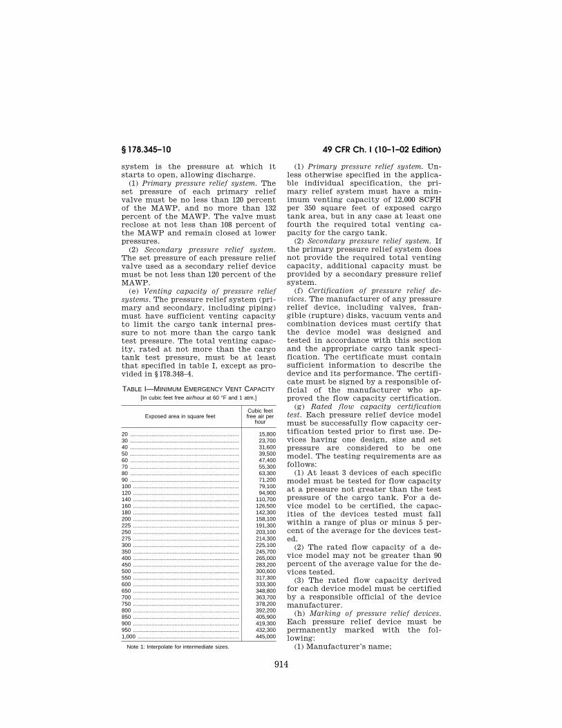
914
49 CFR Ch. I (10–1–02 Edition)§ 178.345–10
system is the pressure at which it starts to open, allowing discharge.
(1) Primary pressure relief system. The set pressure of each primary relief valve must be no less than 120 percent of the MAWP, and no more than 132 percent of the MAWP. The valve must reclose at not less than 108 percent of the MAWP and remain closed at lower pressures.
(2) Secondary pressure relief system. The set pressure of each pressure relief valve used as a secondary relief device must be not less than 120 percent of the MAWP.
(e) Venting capacity of pressure relief systems. The pressure relief system (pri-mary and secondary, including piping) must have sufficient venting capacity to limit the cargo tank internal pres-sure to not more than the cargo tank test pressure. The total venting capac-ity, rated at not more than the cargo tank test pressure, must be at least that specified in table I, except as pro-vided in § 178.348–4.
TABLE I—MINIMUM EMERGENCY VENT CAPACITY [In cubic feet free air/hour at 60 °F and 1 atm.]
Exposed area in square feet Cubic feet free air per
hour
20 ....................................................................... 15,80030 ....................................................................... 23,70040 ....................................................................... 31,60050 ....................................................................... 39,50060 ....................................................................... 47,40070 ....................................................................... 55,30080 ....................................................................... 63,30090 ....................................................................... 71,200100 ..................................................................... 79,100120 ..................................................................... 94,900140 ..................................................................... 110,700160 ..................................................................... 126,500180 ..................................................................... 142,300200 ..................................................................... 158,100225 ..................................................................... 191,300250 ..................................................................... 203,100275 ..................................................................... 214,300300 ..................................................................... 225,100350 ..................................................................... 245,700400 ..................................................................... 265,000450 ..................................................................... 283,200500 ..................................................................... 300,600550 ..................................................................... 317,300600 ..................................................................... 333,300650 ..................................................................... 348,800700 ..................................................................... 363,700750 ..................................................................... 378,200800 ..................................................................... 392,200850 ..................................................................... 405,900900 ..................................................................... 419,300950 ..................................................................... 432,3001,000 .................................................................. 445,000
Note 1: Interpolate for intermediate sizes.
(1) Primary pressure relief system. Un-less otherwise specified in the applica-ble individual specification, the pri-mary relief system must have a min-imum venting capacity of 12,000 SCFH per 350 square feet of exposed cargo tank area, but in any case at least one fourth the required total venting ca-pacity for the cargo tank.
(2) Secondary pressure relief system. If the primary pressure relief system does not provide the required total venting capacity, additional capacity must be provided by a secondary pressure relief system.
(f) Certification of pressure relief de-vices. The manufacturer of any pressure relief device, including valves, fran-gible (rupture) disks, vacuum vents and combination devices must certify that the device model was designed and tested in accordance with this section and the appropriate cargo tank speci-fication. The certificate must contain sufficient information to describe the device and its performance. The certifi-cate must be signed by a responsible of-ficial of the manufacturer who ap-proved the flow capacity certification.
(g) Rated flow capacity certification test. Each pressure relief device model must be successfully flow capacity cer-tification tested prior to first use. De-vices having one design, size and set pressure are considered to be one model. The testing requirements are as follows:
(1) At least 3 devices of each specific model must be tested for flow capacity at a pressure not greater than the test pressure of the cargo tank. For a de-vice model to be certified, the capac-ities of the devices tested must fall within a range of plus or minus 5 per-cent of the average for the devices test-ed.
(2) The rated flow capacity of a de-vice model may not be greater than 90 percent of the average value for the de-vices tested.
(3) The rated flow capacity derived for each device model must be certified by a responsible official of the device manufacturer.
(h) Marking of pressure relief devices. Each pressure relief device must be permanently marked with the fol-lowing:
(1) Manufacturer’s name;
VerDate Dec<13>2002 10:29 Jan 09, 2003 Jkt 197201 PO 00000 Frm 00914 Fmt 8010 Sfmt 8010 Y:\SGML\197201T.XXX 197201T
915
Research and Special Programs Admin., DOT § 178.345–13
(2) Model number; (3) Set pressure, in psig; and (4) Rated flow capacity, in SCFH at
the rating pressure, in psig.
[Amdt. 178–89, 54 FR 25025, June 12, 1989, as amended at 55 FR 21038, May 22, 1990; 55 FR 37062, Sept. 7, 1990; Amdt. 178–89, 56 FR 27877, June 17, 1991; Amdt. 178–105, 59 FR 55175, Nov. 3, 1994; Amdt. 178–118, 61 FR 51341, Oct. 1, 1996; 65 FR 58631, Sept. 29, 2000; 66 FR 45389, Aug. 28, 2001]
§ 178.345–11 Tank outlets. (a) General. As used in this section,
‘‘loading/unloading outlet’’ means any opening in the cargo tank wall used for loading or unloading of lading, as dis-tinguished from outlets such as man-hole covers, vents, vapor recovery de-vices, and similar closures. Cargo tank outlets, closures and associated piping must be protected in accordance with § 178.345–8.
(b) Each cargo tank loading/unload-ing outlet must be equipped with an in-ternal self-closing stop-valve, or alter-natively, with an external stop-valve located as close as practicable to the cargo tank wall. Each cargo tank load-ing/unloading outlet must be in accord-ance with the following provisions:
(1) Each loading/unloading outlet must be fitted with a self-closing sys-tem capable of closing all such outlets in an emergency within 30 seconds of actuation. During normal operations the outlets may be closed manually. The self-closing system must be de-signed according to the following:
(i) Each self-closing system must in-clude a remotely actuated means of closure located more than 10 feet from the loading/unloading outlet where ve-hicle length allows, or on the end of the cargo tank farthest away from the loading/unloading outlet. The actu-ating mechanism must be corrosion-re-sistant and effective in all types of en-vironment and weather.
(ii) If the actuating system is acci-dentally damaged or sheared off during transportation, each loading/unloading outlet must remain securely closed and capable of retaining lading.
(iii) When required by part 173 of this subchapter for materials which are flammable, pyrophoric, oxidizing, or Division 6.1 (poisonous liquid) mate-rials, the remote means of closure
must be capable of thermal activation. The means by which the self-closing system is thermally activated must be located as close as practicable to the primary loading/unloading connection and must actuate the system at a tem-perature not over 250 °F. In addition, outlets on these cargo tanks must be capable of being remotely closed manu-ally or mechanically.
(2) Bottom loading outlets which dis-charge lading into the cargo tank through fixed internal piping above the maximum liquid level of the cargo tank need not be equipped with a self-closing system.
(c) Any loading/unloading outlet ex-tending beyond an internal self-closing stop-valve, or beyond the innermost ex-ternal stop-valve which is part of a self-closing system, must be fitted with another stop-valve or other leak-tight closure at the end of such connection.
(d) Each cargo tank outlet that is not a loading/unloading outlet must be equipped with a stop-valve or other leak-tight closure located as close as practicable to the cargo tank outlet. Any connection extending beyond this closure must be fitted with another stop-valve or other leak-tight closure at the end of such connection.
[Amdt. 178–89, 56 FR 27877, June 17, 1991, as amended by Amdt. 178–97, 57 FR 45465, Oct. 1, 1992; Amdt. 178–118, 61 FR 51341, Oct. 1, 1996]
§ 178.345–12 Gauging devices. Each cargo tank, except a cargo tank
intended to be filled by weight, must be equipped with a gauging device that in-dicates the maximum permitted liquid level to within 0.5 percent of the nomi-nal capacity as measured by volume or liquid level. Gauge glasses are not per-mitted.
[Amdt. 178–89, 55 FR 37062, Sept. 7, 1990, as amended by Amdt. 178–118, 61 FR 51342, Oct. 1, 1996]
§ 178.345–13 Pressure and leakage tests.
(a) Each cargo tank must be pressure and leakage tested in accordance with this section.
(b) Pressure test. Each cargo tank or cargo tank compartment must be test-ed hydrostatically or pneumatically. Each cargo tank of a multi-cargo tank motor vehicle must be tested with the
VerDate Dec<13>2002 10:29 Jan 09, 2003 Jkt 197201 PO 00000 Frm 00915 Fmt 8010 Sfmt 8010 Y:\SGML\197201T.XXX 197201T
916
49 CFR Ch. I (10–1–02 Edition)§ 178.345–14
adjacent cargo tanks empty and at at-mospheric pressure. Each closure, ex-cept pressure relief devices and load-ing/unloading venting devices rated at less than the prescribed test pressure, must be in place during the test. If the venting device is not removed during the test, such device must be rendered inoperative by a clamp, plug or other equally effective restraining device, which may not prevent the detection of leaks, or damage the device. Restrain-ing devices must be removed imme-diately after the test is completed.
(1) Hydrostatic method. Each cargo tank, including its domes, must be filled with water or other liquid having similar viscosity, the temperature of which may not exceed 100 °F. The cargo tank must then be pressurized as pre-scribed in the applicable specification. The pressure must be gauged at the top of the cargo tank. The prescribed test pressure must be maintained for at least 10 minutes during which time the cargo tank must be inspected for leak-age, bulging, or other defect.
(2) Pneumatic method. A pneumatic test may be used in place of the hydro-static test. However, pneumatic pres-sure testing may involve higher risk than hydrostatic testing. Therefore, suitable safeguards must be provided to protect personnel and facilities should failure occur during the test. The cargo tank must be pressurized with air or an inert gas. Test pressure must be reached gradually by increasing the pressure to one half of test pressure. Thereafter, the pressure must be in-creased in steps of approximately one tenth of the test pressure until test pressure is reached. Test pressure must be held for at least 5 minutes. The pres-sure must then be reduced to the in-spection pressure which must be main-tained while the entire cargo tank sur-face is inspected for leakage and other sign of defects. The inspection method must consist of coating all joints and fittings with a solution of soap and water or other equally sensitive meth-od.
(c) Leakage test. The cargo tank with all its accessories in place and operable must be leak tested at not less than 80 percent of tank’s MAWP with the pres-sure maintained for at least 5 minutes.
(d) Any cargo tank that leaks, bulges or shows any other sign of defect must be rejected. Rejected cargo tanks must be suitably repaired and retested suc-cessfully prior to being returned to service. The retest after any repair must use the same method of test under which the cargo tank was origi-nally rejected.
[Amdt. 178–89, 54 FR 25026, June 12, 1989, as amended at 55 FR 37063, Sept. 7, 1990; Amdt. 178–105, 59 FR 55176, Nov. 3, 1994; Amdt. 178–118, 61 FR 51342, Oct. 1, 1996; 65 FR 58631, Sept. 29, 2000]
§ 178.345–14 Marking. (a) General. The manufacturer shall
certify that each cargo tank motor ve-hicle has been designed, constructed and tested in accordance with the ap-plicable Specification DOT 406, DOT 407 or DOT 412 (§§ 178.345, 178.346, 178.347, 178.348) cargo tank requirements, and when applicable, with the ASME Code. The certification shall be accomplished by marking the cargo tank as pre-scribed in paragraphs (b) and (c) of this section, and by preparing the certifi-cate prescribed in § 178.345–15. Metal plates prescribed by paragraphs (b), (c), (d) and (e) of this section, must be per-manently attached to the cargo tank or its integral supporting structure, by brazing, welding or other suitable means. These plates must be affixed on the left side of the vehicle near the front of the cargo tank (or the frontmost cargo tank of a multi-cargo tank motor vehicle), in a place readily accessible for inspection. The plates must be permanently and plainly marked in English by stamping, em-bossing or other means in characters at least 3⁄16 inch high. The information re-quired by paragraphs (b) and (c) of this section may be combined on one speci-fication plate.
(b) Nameplate. Each cargo tank must have a corrosion resistant nameplate permanently attached to it. The fol-lowing information, in addition to any applicable information required by the ASME Code, must be marked on the tank nameplate (parenthetical abbre-viations may be used):
(1) DOT Specification number DOT XXX (DOT XXX), where ‘‘XXX’’ is re-placed with the applicable specification number.
VerDate Dec<13>2002 10:29 Jan 09, 2003 Jkt 197201 PO 00000 Frm 00916 Fmt 8010 Sfmt 8010 Y:\SGML\197201T.XXX 197201T
917
Research and Special Programs Admin., DOT § 178.345–14
(2) Original test date, month and year (Orig. Test Date).
(3) Tank MAWP in psig. (4) Cargo tank test pressure (Test P),
in psig. (5) Cargo tank design temperature
range (Design temp. range),l °F to l °F.
(6) Nominal capacity (Water cap.), in gallons.
(7) Maximum design density of lading (Max. lading density), in pounds per gallon.
(8) Material specification number—shell (Shell matl, yyy***), where ‘‘yyy’’ is replaced by the alloy designation and ‘‘***’’ by the alloy type.
(9) Material specification number—heads (Head matl, yyy***), where ‘‘yyy’’ is replaced by the alloy designa-tion and ‘‘***’’ by the alloy type.
NOTE: When the shell and heads materials are the same thickness, they may be com-bined, (Shell&head matl, yyy***).
(10) Weld material (Weld matl.). (11) Minimum thickness—shell (Min.
shell-thick), in inches. When minimum shell thicknesses are not the same for different areas, show (top l, side l, bottom l, in inches).
(12) Minimum thickness—heads (Min. heads thick.), in inches.
(13) Manufactured thickness—shell (Mfd. shell thick.), top l, side l, bot-tom l, in inches. (Required when addi-tional thickness is provided for corro-sion allowance.)
(14) Manufactured thickness—heads (Mfd. heads thick.), in inches. (Re-quired when additional thickness is provided for corrosion allowance.)
(15) Exposed surface area, in square feet.
(c) Specification plate. Each cargo tank motor vehicle must have an addi-tional corrosion resistant metal speci-fication plate attached to it. The speci-fication plate must contain the fol-lowing information (parenthetical ab-breviations may be used):
(1) Cargo tank motor vehicle manu-facturer (CTMV mfr.).
(2) Cargo tank motor vehicle certifi-cation date (CTMV cert. date), if dif-ferent from the cargo tank certifi-cation date.
(3) Cargo tank manufacturer (CT mfr.).
(4) Cargo tank date of manufacture (CT date of mfr.), month and year.
(5) Maximum weight of lading (Max. payload), in pounds.
(6) Maximum loading rate in gallons per minute (Max. load rate, GPM) at maximum loading pressure ll psig.
(7) Maximum unloading rate in gal-lons per minute (Max. unload rate, GPM), at maximum unloading pressure ll psig.
(8) Lining material (Lining), if appli-cable.
(9) Heating system design pressure (Heating sys. press.), in psig, if applica-ble.
(10) Heating system design tempera-ture (Heating sys. temp.), in °F, if ap-plicable.
(d) Multi-cargo tank motor vehicle. For a multi-cargo tank motor vehicle hav-ing all its cargo tanks not separated by any void, the information required by paragraphs (b) and (c) of this section may be combined on one specification plate. When separated by a void, each cargo tank must have an individual nameplate as required in paragraph (b) of this section, unless all cargo tanks are made by the same manufacturer with the same materials, manufactured thickness, minimum thickness and to the same specification. The cargo tank motor vehicle may have a combined nameplate and specification plate. When only one plate is used, the plate must be visible and not covered by in-sulation. The required information must be listed on the plate from front to rear in the order of the cor-responding cargo tank location.
(e) Variable specification cargo tank. Each variable specification cargo tank must have a corrosion resistant metal variable specification plate attached to it. The mounting of this variable speci-fication plate must be such that only the plate identifying the applicable specification under which the tank is being operated is legible.
(1) The following information must be included (parenthetical abbrevia-tions are authorized):
Specification DOT XXX (DOT XXX), where ‘‘XXX’’ is replaced with the applicable speci-fication number.
VerDate Dec<13>2002 10:29 Jan 09, 2003 Jkt 197201 PO 00000 Frm 00917 Fmt 8010 Sfmt 8010 Y:\SGML\197201T.XXX 197201T

918
49 CFR Ch. I (10–1–02 Edition)§ 178.345–15
Equipment required Required rating 1
Pressure relief devices: Pressure actuated type .... llllll
Frangible type ................. llllll
Lading discharge devices llllll
Top ................................... llllll
Bottom ............................. llllll
Pressure unloading fitting llllll
Closures: Manhole ........................... llllll
Fill openings .................... llllll
Discharge openings .......... llllll
1 Required rating—to meet the applicable specification.
(2) If no change of information in the specification plate is required, the let-ters ‘‘NC’’ must follow the rating re-quired. If the cargo tank is not so equipped, the word ‘‘None’’ must be in-serted.
(3) Those parts to be changed or added must be stamped with the appro-priate MC or DOT Specification mark-ings.
(4) The alterations that must be made in order for the tank to be modi-fied from one specification to another must be clearly indicated on the manu-facturer’s certificate and on the vari-able specification plate.
[Amdt. 178–89, 54 FR 25027, June 12, 1989, as amended at 55 FR 37063, Sept. 7, 1990; Amdt. 178–99, 58 FR 51534, Oct. 1, 1993; Amdt. 178–104, 59 FR 49135, Sept. 26, 1994; Amdt. 178–105, 59 FR 55176, Nov. 3, 1994; 60 FR 17402, Apr. 5, 1995; Amdt. 178–118, 61 FR 51342, Oct. 1, 1996; 66 FR 45389, Aug. 28, 2001]
§ 178.345–15 Certification. (a) At or before the time of delivery,
the manufacturer of a cargo tank motor vehicle must provide certifi-cation documents to the owner of the cargo tank motor vehicle. The registra-tion numbers of the manufacturer, the Design Certifying Engineer, and the Registered Inspector, as appropriate, must appear on the certificates (see subpart F, part 107 in subchapter A of this chapter).
(b) The manufacturer of a cargo tank motor vehicle made to any of these specifications must provide:
(1) For each design type, a certificate signed by a responsible official of the manufacturer and a Design Certifying Engineer certifying that the cargo tank motor vehicle design meets the applicable specification; and
(2) For each ASME cargo tank, a cargo tank manufacturer’s data report as required by the ASME Code. For each cargo tank motor vehicle, a cer-tificate signed by a responsible official of the manufacturer and a Registered Inspector certifying that the cargo tank motor vehicle is constructed, tested and completed in conformance with the applicable specification.
(c) The manufacturer of a variable specification cargo tank motor vehicle must provide:
(1) For each design type, a certificate signed by a responsible official of the manufacturer and a Design Certifying Engineer certifying that the cargo tank motor vehicle design meets the applicable specifications; and
(2) For each variable specification cargo tank motor vehicle, a certificate signed by a responsible official of the manufacturer and a Registered Inspec-tor certifying that the cargo tank motor vehicle is constructed, tested and completed in conformance with the applicable specifications. The certifi-cate must include all the information required and marked on the variable specification plate.
(d) In the case of a cargo tank motor vehicle manufactured in two or more stages, each manufacturer who per-forms a manufacturing operation on the incomplete vehicle or portion thereof shall provide to the succeeding manufacturer, at or before the time of delivery, a certificate covering the par-ticular operation performed by that manufacturer, including any certifi-cates received from previous manufac-turers, Registered Inspectors, and De-sign Certifying Engineers. Each certifi-cate must indicate the portion of the complete cargo tank motor vehicle rep-resented thereby, such as basic cargo tank fabrication, insulation, jacket, lining, or piping. The final manufac-turer shall provide all applicable cer-tificates to the owner.
(e) Specification shortages. If a cargo tank is manufactured which does not meet all applicable specification re-quirements, thereby requiring subse-quent manufacturing involving the in-stallation of additional components, parts, appurtenances or accessories, the cargo tank manufacturer may affix the name plate and specification plate,
VerDate Dec<13>2002 10:29 Jan 09, 2003 Jkt 197201 PO 00000 Frm 00918 Fmt 8010 Sfmt 8010 Y:\SGML\197201T.XXX 197201T

919
Research and Special Programs Admin., DOT § 178.346–1
as required by § 178.345–14 (b) and (c), without the original date of certifi-cation stamped on the specification plate. The manufacturer shall state the specification requirements not com-plied with on the manufacturer’s Cer-tificate of Compliance. When the cargo tank is brought into full compliance with the applicable specification, the Registered Inspector shall stamp the date of compliance on the specification plate. The Registered Inspector shall issue a Certificate of Compliance stat-ing details of the particular operations performed on the cargo tank, and the date and person (manufacturer, carrier, or repair organization) accomplishing the compliance.
[Amdt. 178–89, 55 FR 37063, Sept. 7, 1990, as amended by Amdt. 178–98, 58 FR 33306, June 16, 1993; Amdt. 178–105, 59 FR 55176, Nov. 3, 1994; Amdt. 178–118, 61 FR 51342, Oct. 1, 1996]
§ 178.346 Specification DOT 406; cargo tank motor vehicle.
§ 178.346–1 General requirements. (a) Each Specification DOT 406 cargo
tank motor vehicle must meet the gen-eral design and construction require-ments in § 178.345, in addition to the specific requirements contained in this section.
(b) MAWP: The MAWP of each cargo tank must be no lower than 2.65 psig and no higher than 4 psig.
(c) Vacuum loaded cargo tanks must not be constructed to this specifica-tion.
(d) Each cargo tank must be ‘‘con-structed in accordance with the ASME Code’’ except as modified herein:
(1) The record-keeping requirements contained in the ASME Code Section VIII, Division I do not apply. Parts UG–90 thru 94 of Section VIII, Division I do not apply. Inspection and certification must be made by an inspector reg-istered in accordance with subpart F of part 107.
(2) Loadings must be as prescribed in § 178.345–3.
(3) The knuckle radius of flanged heads must be at least three times the material thickness, and in no case less than 0.5 inch. Stuffed (inserted) heads may be attached to the shell by a fillet weld. The knuckle radius and dish ra-dius versus diameter limitations of
UG–32 do not apply. Shell sections of cargo tanks designed with a non-cir-cular cross section need not be given a preliminary curvature, as prescribed in UG–79(b).
(4) Marking, certification, data re-ports, and nameplates must be as pre-scribed in §§ 178.345–14 and 178.345–15.
(5) Manhole closure assemblies must conform to §§ 178.345–5 and 178.346–5.
(6) Pressure relief devices must be as prescribed in § 178.345–10.
(7) The hydrostatic or pneumatic test must be as prescribed in § 178.345–13.
(8) The following paragraphs in parts UG and UW of the ASME Code, Section VIII, Division I do not apply: UG–11, UG–12, UG–22(g), UG–32(e), UG–34, UG–35, UG–44, UG–76, UG–77, UG–80, UG–81, UG–96, UG–97, UW–13(b)(2), UW–13.1(f) and the dimensional requirements found in Figure UW–13.1.
(9) Single full fillet lap joints with-out plug welds may be used for arc or gas welded longitudinal seams without radiographic examination under the following conditions:
(i) For a truck-mounted cargo tank, no more than two such joints may be used on the top half of the tank and no more than two joints may be used on the bottom half. They may not be lo-cated farther from the top and bottom centerline than 16 percent of the shell’s circumference.
(ii) For a self-supporting cargo tank, no more than two such joints may be used on the top of the tank. They may not be located farther from the top centerline than 12.5 percent of the shell’s circumference.
(iii) Compliance test. Two test speci-mens of the material to be used in the manufacture of a cargo tank must be tested to failure in tension. The test specimens must be of the same thicknesses and joint configuration as the cargo tank, and joined by the same welding procedures. The test specimens may represent all the tanks that are made of the same materials and weld-ing procedures, have the same joint configuration, and are made in the same facility within 6 months after the tests are completed. Before welding, the fit-up of the joints on the test specimens must represent production conditions that would result in the least joint strength. Evidence of joint
VerDate Dec<13>2002 10:29 Jan 09, 2003 Jkt 197201 PO 00000 Frm 00919 Fmt 8010 Sfmt 8010 Y:\SGML\197201T.XXX 197201T
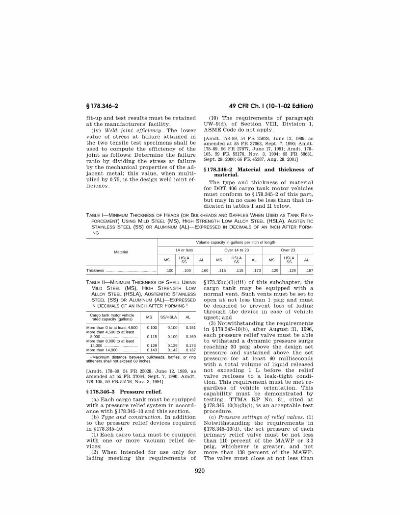
920
49 CFR Ch. I (10–1–02 Edition)§ 178.346–2
fit-up and test results must be retained at the manufacturers’ facility.
(iv) Weld joint efficiency. The lower value of stress at failure attained in the two tensile test specimens shall be used to compute the efficiency of the joint as follows: Determine the failure ratio by dividing the stress at failure by the mechanical properties of the ad-jacent metal; this value, when multi-plied by 0.75, is the design weld joint ef-ficiency.
(10) The requirements of paragraph UW–9(d), of Section VIII, Division 1, ASME Code do not apply.
[Amdt. 178–89, 54 FR 25028, June 12, 1989, as amended at 55 FR 37063, Sept. 7, 1990; Amdt. 178–89, 56 FR 27877, June 17, 1991; Amdt. 178–105, 59 FR 55176, Nov. 3, 1994; 65 FR 58631, Sept. 29, 2000; 66 FR 45387, Aug. 28, 2001]
§ 178.346–2 Material and thickness of material.
The type and thickness of material for DOT 406 cargo tank motor vehicles must conform to § 178.345–2 of this part, but may in no case be less than that in-dicated in tables I and II below.
TABLE I—MINIMUM THICKNESS OF HEADS (OR BULKHEADS AND BAFFLES WHEN USED AS TANK REIN-FORCEMENT) USING MILD STEEL (MS), HIGH STRENGTH LOW ALLOY STEEL (HSLA), AUSTENITIC STAINLESS STEEL (SS) OR ALUMINUM (AL)—EXPRESSED IN DECIMALS OF AN INCH AFTER FORM-ING
Material
Volume capacity in gallons per inch of length
14 or less Over 14 to 23 Over 23
MS HSLA SS AL MS HSLA
SS AL MS HSLA SS AL
Thickness .............................................. .100 .100 .160 .115 .115 .173 .129 .129 .187
TABLE II—MINIMUM THICKNESS OF SHELL USING MILD STEEL (MS), HIGH STRENGTH LOW ALLOY STEEL (HSLA), AUSTENITIC STAINLESS STEEL (SS) OR ALUMINUM (AL)—EXPRESSED IN DECIMALS OF AN INCH AFTER FORMING 1
Cargo tank motor vehicle rated capacity (gallons) MS SS/HSLA AL
More than 0 to at least 4,500 0.100 0.100 0.151More than 4,500 to at least
8,000 ................................. 0.115 0.100 0.160More than 8,000 to at least
14,000 ............................... 0.129 0.129 0.173More than 14,000 ................. 0.143 0.143 0.187
1 Maximum distance between bulkheads, baffles, or ring stiffeners shall not exceed 60 inches.
[Amdt. 178–89, 54 FR 25028, June 12, 1989, as amended at 55 FR 37064, Sept. 7, 1990; Amdt. 178–105, 59 FR 55176, Nov. 3, 1994]
§ 178.346–3 Pressure relief. (a) Each cargo tank must be equipped
with a pressure relief system in accord-ance with § 178.345–10 and this section.
(b) Type and construction. In addition to the pressure relief devices required in § 178.345–10:
(1) Each cargo tank must be equipped with one or more vacuum relief de-vices;
(2) When intended for use only for lading meeting the requirements of
§ 173.33(c)(1)(iii) of this subchapter, the cargo tank may be equipped with a normal vent. Such vents must be set to open at not less than 1 psig and must be designed to prevent loss of lading through the device in case of vehicle upset; and
(3) Notwithstanding the requirements in § 178.345–10(b), after August 31, 1996, each pressure relief valve must be able to withstand a dynamic pressure surge reaching 30 psig above the design set pressure and sustained above the set pressure for at least 60 milliseconds with a total volume of liquid released not exceeding 1 L before the relief valve recloses to a leak-tight condi-tion. This requirement must be met re-gardless of vehicle orientation. This capability must be demonstrated by testing. TTMA RP No. 81, cited at § 178.345–10(b)(3)(i), is an acceptable test procedure.
(c) Pressure settings of relief valves. (1) Notwithstanding the requirements in § 178.345–10(d), the set pressure of each primary relief valve must be not less than 110 percent of the MAWP or 3.3 psig, whichever is greater, and not more than 138 percent of the MAWP. The valve must close at not less than
VerDate Dec<13>2002 10:29 Jan 09, 2003 Jkt 197201 PO 00000 Frm 00920 Fmt 8010 Sfmt 8010 Y:\SGML\197201T.XXX 197201T

921
Research and Special Programs Admin., DOT § 178.347–1
the MAWP and remain closed at lower pressures.
(2) Each vacuum relief device must be set to open at no more than 6 ounces vacuum.
(d) Venting capacities. (1) Notwith-standing the requirements in § 178.345–10 (e) and (g), the primary pressure re-lief valve must have a venting capacity of at least 6,000 SCFH, rated at not greater than 125 percent of the tank test pressure and not greater than 3 psig above the MAWP. The venting ca-pacity required in § 178.345–10(e) may be rated at these same pressures.
(2) Each vacuum relief system must have sufficient capacity to limit the vacuum to 1 psig.
(3) If pressure loading or unloading devices are provided, the relief system must have adequate vapor and liquid capacity to limit the tank pressure to the cargo tank test pressure at max-imum loading or unloading rate. The maximum loading and unloading rates must be included on the metal speci-fication plate.
[Amdt. 178–89, 54 FR 25029, June 12, 1989, as amended at 55 FR 37064, Sept. 7, 1990; Amdt. 178–105, 59 FR 55176, Nov. 3, 1994. Redesig-nated by Amdt. 178–112, 61 FR 18934, Apr. 29, 1996; 66 FR 45389, Aug. 28, 2001]
§ 178.346–4 Outlets. (a) All outlets on each tank must
conform to § 178.345–11 and this section. (b) External self-closing stop-valves
are not authorized as an alternative to internal self-closing stop-valves on loading/unloading outlets.
[Amdt. 178–89, 54 FR 25029, June 12, 1989. Re-designated by Amdt. 178–112, 61 FR 18934, Apr. 29, 1996]
§ 178.346–5 Pressure and leakage tests. (a) Each cargo tank must be tested in
accordance with § 178.345–13 and this section.
(b) Pressure test. Test pressure must be as follows:
(1) Using the hydrostatic test meth-od, the test pressure must be the great-er of 5.0 psig or 1.5 times the cargo tank MAWP.
(2) Using the pneumatic test method, the test pressure must be the greater of 5.0 psig or 1.5 times the cargo tank MAWP, and the inspection pressure must be the cargo tank MAWP.
(c) Leakage test. Cargo tanks equipped with vapor collection equipment may be leakage tested in accordance with the Environmental Protection Agen-cy’s ‘‘Method 27—Determination of Vapor Tightness of Gasoline Delivery Tank Using Pressure-Vacuum Test,’’ as set forth in 40 CFR part 60, appendix A. Acceptance criteria are found at 40 CFR 60.501 and 60.601.
[Amdt. 178–89, 54 FR 25029, June 12, 1989, as amended at 55 FR 37064, Sept. 7, 1990; Amdt. 178–105, 59 FR 55176, Nov. 3, 1994. Redesig-nated by Amdt. 178–112, 61 FR 18934, Apr. 29, 1996]
§ 178.347 Specification DOT 407; cargo tank motor vehicle.
§ 178.347–1 General requirements. (a) Each specification DOT 407 cargo
tank motor vehicle must conform to the general design and construction re-quirements in § 178.345 in addition to the specific requirements contained in this section.
(b) Each tank must be of a circular cross-section and have an MAWP of at least 25 psig.
(c) Any cargo tank built to this spec-ification with a MAWP greater than 35 psig and each tank designed to be load-ed by vacuum must be ‘‘constructed and certified in accordance with the ASME Code’’. The external design pres-sure for a cargo tank loaded by vacuum must be at least 15 psig.
(d) Each cargo tank built to this specification with MAWP of 35 psig or less must be ‘‘constructed in accord-ance with the ASME Code’’ except as modified herein:
(1) The record-keeping requirements contained in the ASME Code, Section VIII, Division I, do not apply. The in-spection requirements of parts UG–90 thru 94 do not apply. Inspection and certification must be made by an in-spector registered in accordance with subpart F of part 107.
(2) Loadings must be as prescribed in § 178.345–3.
(3) The knuckle radius of flanged heads must be at least three times the material thickness, and in no case less than 0.5 inch. Stuffed (inserted) heads may be attached to the shell by a fillet weld. The knuckle radius and dish ra-dius versus diameter limitations of
VerDate Dec<13>2002 10:29 Jan 09, 2003 Jkt 197201 PO 00000 Frm 00921 Fmt 8010 Sfmt 8010 Y:\SGML\197201T.XXX 197201T
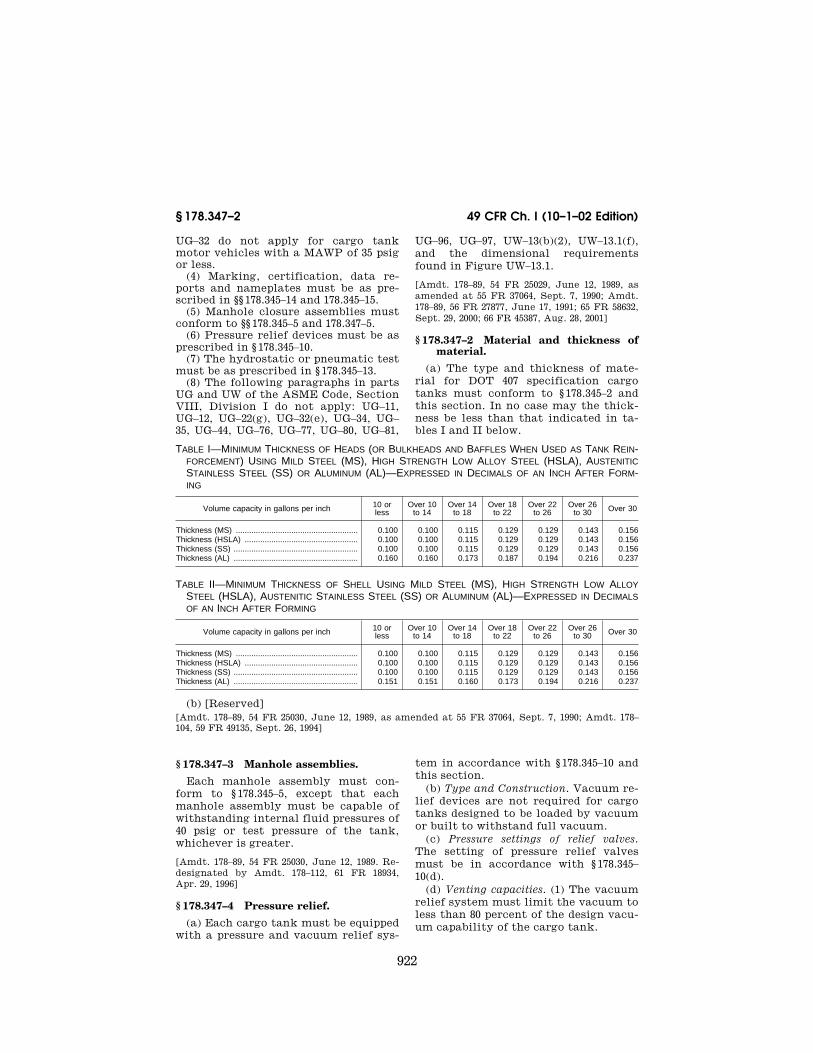
922
49 CFR Ch. I (10–1–02 Edition)§ 178.347–2
UG–32 do not apply for cargo tank motor vehicles with a MAWP of 35 psig or less.
(4) Marking, certification, data re-ports and nameplates must be as pre-scribed in §§ 178.345–14 and 178.345–15.
(5) Manhole closure assemblies must conform to §§ 178.345–5 and 178.347–5.
(6) Pressure relief devices must be as prescribed in § 178.345–10.
(7) The hydrostatic or pneumatic test must be as prescribed in § 178.345–13.
(8) The following paragraphs in parts UG and UW of the ASME Code, Section VIII, Division I do not apply: UG–11, UG–12, UG–22(g), UG–32(e), UG–34, UG–35, UG–44, UG–76, UG–77, UG–80, UG–81,
UG–96, UG–97, UW–13(b)(2), UW–13.1(f), and the dimensional requirements found in Figure UW–13.1.
[Amdt. 178–89, 54 FR 25029, June 12, 1989, as amended at 55 FR 37064, Sept. 7, 1990; Amdt. 178–89, 56 FR 27877, June 17, 1991; 65 FR 58632, Sept. 29, 2000; 66 FR 45387, Aug. 28, 2001]
§ 178.347–2 Material and thickness of material.
(a) The type and thickness of mate-rial for DOT 407 specification cargo tanks must conform to § 178.345–2 and this section. In no case may the thick-ness be less than that indicated in ta-bles I and II below.
TABLE I—MINIMUM THICKNESS OF HEADS (OR BULKHEADS AND BAFFLES WHEN USED AS TANK REIN-FORCEMENT) USING MILD STEEL (MS), HIGH STRENGTH LOW ALLOY STEEL (HSLA), AUSTENITIC STAINLESS STEEL (SS) OR ALUMINUM (AL)—EXPRESSED IN DECIMALS OF AN INCH AFTER FORM-ING
Volume capacity in gallons per inch 10 or less
Over 10 to 14
Over 14 to 18
Over 18 to 22
Over 22 to 26
Over 26 to 30 Over 30
Thickness (MS) ....................................................... 0.100 0.100 0.115 0.129 0.129 0.143 0.156Thickness (HSLA) ................................................... 0.100 0.100 0.115 0.129 0.129 0.143 0.156Thickness (SS) ........................................................ 0.100 0.100 0.115 0.129 0.129 0.143 0.156Thickness (AL) ........................................................ 0.160 0.160 0.173 0.187 0.194 0.216 0.237
TABLE II—MINIMUM THICKNESS OF SHELL USING MILD STEEL (MS), HIGH STRENGTH LOW ALLOY STEEL (HSLA), AUSTENITIC STAINLESS STEEL (SS) OR ALUMINUM (AL)—EXPRESSED IN DECIMALS OF AN INCH AFTER FORMING
Volume capacity in gallons per inch 10 or less
Over 10 to 14
Over 14 to 18
Over 18 to 22
Over 22 to 26
Over 26 to 30 Over 30
Thickness (MS) ....................................................... 0.100 0.100 0.115 0.129 0.129 0.143 0.156Thickness (HSLA) ................................................... 0.100 0.100 0.115 0.129 0.129 0.143 0.156Thickness (SS) ........................................................ 0.100 0.100 0.115 0.129 0.129 0.143 0.156Thickness (AL) ........................................................ 0.151 0.151 0.160 0.173 0.194 0.216 0.237
(b) [Reserved][Amdt. 178–89, 54 FR 25030, June 12, 1989, as amended at 55 FR 37064, Sept. 7, 1990; Amdt. 178–104, 59 FR 49135, Sept. 26, 1994]
§ 178.347–3 Manhole assemblies.
Each manhole assembly must con-form to § 178.345–5, except that each manhole assembly must be capable of withstanding internal fluid pressures of 40 psig or test pressure of the tank, whichever is greater.
[Amdt. 178–89, 54 FR 25030, June 12, 1989. Re-designated by Amdt. 178–112, 61 FR 18934, Apr. 29, 1996]
§ 178.347–4 Pressure relief.
(a) Each cargo tank must be equipped with a pressure and vacuum relief sys-
tem in accordance with § 178.345–10 and this section.
(b) Type and Construction. Vacuum re-lief devices are not required for cargo tanks designed to be loaded by vacuum or built to withstand full vacuum.
(c) Pressure settings of relief valves. The setting of pressure relief valves must be in accordance with § 178.345–10(d).
(d) Venting capacities. (1) The vacuum relief system must limit the vacuum to less than 80 percent of the design vacu-um capability of the cargo tank.
VerDate Dec<13>2002 10:29 Jan 09, 2003 Jkt 197201 PO 00000 Frm 00922 Fmt 8010 Sfmt 8010 Y:\SGML\197201T.XXX 197201T

923
Research and Special Programs Admin., DOT § 178.348–2
(2) If pressure loading or unloading devices are provided, the relief system must have adequate vapor and liquid capacity to limit the tank pressure to the cargo tank test pressure at max-imum loading or unloading rate. The maximum loading or unloading rate must be included on the metal speci-fication plate.
[Amdt. 178–89, 54 FR 25030, June 12, 1989, as amended at 55 FR 37064, Sept. 7, 1990. Redes-ignated by Amdt. 178–112, 61 FR 18934, Apr. 29, 1996]
§ 178.347–5 Pressure and leakage test.
(a) Each cargo tank must be tested in accordance with § 178.345–13 and this section.
(b) Pressure test. Test pressure must be as follows:
(1) Using the hydrostatic test meth-od, the test pressure must be at least 40 psig or 1.5 times tank MAWP, which-ever is greater.
(2) Using the pneumatic test method, the test pressure must be 40 psig or 1.5 times tank MAWP, whichever is great-er, and the inspection pressure is tank MAWP.
[Amdt. 178–89, 54 FR 25030, June 12, 1989. Re-designated by Amdt. 178–112, 61 FR 18934, Apr. 29, 1996]
§ 178.348 Specification DOT 412; cargo tank motor vehicle.
§ 178.348–1 General requirements.
(a) Each specification DOT 412 cargo tank motor vehicle must conform to the general design and construction re-quirements in § 178.345 in addition to the specific requirements of this sec-tion.
(b) The MAWP of each cargo tank must be at least 5 psig.
(c) The MAWP for each cargo tank designed to be loaded by vacuum must be at least 25 psig internal and 15 psig external.
(d) Each cargo tank having a MAWP greater than 15 psig must be of circular cross-section.
(e) Each cargo tank having a— (1) MAWP greater than 15 psig must
be ‘‘constructed and certified in con-formance with the ASME Code’’; or
(2) MAWP of 15 psig or less must be ‘‘constructed in accordance with the
ASME Code,’’ except as modified here-in:
(i) The recordkeeping requirements contained in the ASME Code, Section VIII, Division I, do not apply. Parts UG–90 thru 94 of Section VIII, Division I do not apply. Inspection and certifi-cation must be made by an inspector registered in accordance with subpart F of part 107.
(ii) Loadings must be as prescribed in § 178.345–3.
(iii) The knuckle radius of flanged heads must be at least three times the material thickness, and in no case less than 0.5 inch. Stuffed (inserted) heads may be attached to the shell by a fillet weld. The knuckle radius and dish ra-dius versus diameter limitations of UG–32 do not apply for cargo tank motor vehicles with a MAWP of 15 psig or less. Shell sections of cargo tanks designed with a non-circular cross sec-tion need not be given a preliminary curvature, as prescribed in UG–79(b).
(iv) Marking, certification, data re-ports, and nameplates must be as pre-scribed in §§ 178.345–14 and 178.345–15.
(v) Manhole closure assemblies must conform to §§ 178.345–5 and 178.348–5.
(vi) Pressure relief devices must be as prescribed in § 178.345–10.
(vii) The hydrostatic or pneumatic test must be as prescribed in § 178.345–13.
(viii) The following paragraphs in parts UG and UW of the ASME Code, Section VIII, Division I do not apply: UG–11, UG–12, UG–22(g), UG–32(e), UG–34, UG–35, UG–44, UG–76, UG–77, UG–80, UG–81, UG–96, UG–97, UW–13(b)(2), UW–13.1(f), and the dimensional require-ments found in Figure UW–13.1.
[Amdt. 178–89, 54 FR 25031, June 12, 1989, as amended at 55 FR 37065, Sept. 7, 1990; Amdt. 178–89, 56 FR 27877, June 17, 1991; 65 FR 58632, Sept. 29, 2000]
§ 178.348–2 Material and thickness of material.
(a) The type and thickness of mate-rial for DOT 412 cargo tanks must con-form to § 178.345–2 of this part, but in no case may the thickness be less than that indicated in tables I and II below.
VerDate Dec<13>2002 10:29 Jan 09, 2003 Jkt 197201 PO 00000 Frm 00923 Fmt 8010 Sfmt 8010 Y:\SGML\197201T.XXX 197201T

924
49 CFR C
h. I (10–1–02 Editio
n)§
178.348–2
TABLE I—MINIMUM THICKNESS OF HEADS (OR BULKHEADS AND BAFFLES WHEN USED AS TANK REINFORCEMENT) USING MILD STEEL (MS), HIGH STRENGTH LOW ALLOY STEEL (HSLA), AUSTENITIC STAINLESS STEEL (SS) OR ALUMINUM (AL)—EXPRESSED IN DECIMALS OF AN INCH AFTER FORMING
Volume capacity (gallons per inch) 10 or less Over 10 to 14 Over 14 to 18 18 and over
Lading density at 60 °F in pounds per gallon ..................................... 10 lbs and less
Over 10 to
13 lbs
Over 13 to
16 lbs
Over 16 lbs
10 lbs and less
Over 10 to
13 lbs
Over 13 to
16 lbs
Over 16 lbs
10 lbs and less
Over 10 to
13 lbs
Over 13 to
16 lbs
10 lbs and less
Over 10 to
13 lbs
Over 13 to
16 lbs Thickness (inch), steel ......................................................................... .100 .129 .157 .187 .129 .157 .187 .250 .157 .250 .250 .157 .250 .312Thickness (inch), aluminum ................................................................. .144 .187 .227 .270 .187 .227 .270 .360 .227 .360 .360 .227 .360 .450
TABLE II—MINIMUM THICKNESS OF SHELL USING MILD STEEL (MS), HIGH STRENGTH LOW ALLOY STEEL (HSLA) OR AUSTENITIC STAINLESS STEEL (SS) OR ALUMINUM (AL)—EXPRESSED IN DECIMALS OF AN INCH AFTER FORMING
Volume capacity in gallons per inch 10 or less Over 10 to 14 Over 14 to 18 18 and over
Lading density at 60 °F in pounds per gallon ..................................... 10 lbs and less
Over 10 to
13 lbs
Over 13 to
16 lbs
Over 16 lbs
10 lbs and less
Over 10 to
13 lbs
Over 13 to
16 lbs
Over 16 lbs
10 lbs and less
Over 10 to
13 lbs
Over 13 to
16 lbs
10 lbs and less
Over 10 to
13 lbs
Over 13 to
16 lbs Thickness (steel):
Distances between heads (and bulkheads baffles and ring stiff-eners when used as tank reinforcement):
36 in. or less .......................................................................... .100 .129 .157 .187 .100 .129 .157 .187 .100 .129 .157 .129 .157 .187Over 36 in. to 54 inches ........................................................ .100 .129 .157 .187 .100 .129 .157 .187 .129 .157 .187 .157 .250 .250Over 54 in. to 60 inches ........................................................ .100 .129 .157 .187 .129 .157 .187 .250 .157 .250 .250 .187 .250 .312
Thickness (aluminum): Distances between heads (and bulkheads baffles and ring stiff-
eners when used as tank reinforcement): 36 in. or less .......................................................................... .144 .187 .227 .270 .144 .187 .227 .270 .144 .187 .227 .187 .227 .270Over 36 in. to 54 inches ........................................................ .144 .187 .227 .270 .144 .187 .227 .270 .187 .227 .270 .157 .360 .360Over 54 in. to 60 inches ........................................................ .144 .187 .227 .270 .187 .227 .270 .360 .227 .360 .360 .270 .360 .450
VerD
ate Dec<
13>2002
10:29 Jan 09, 2003Jkt 197201
PO
00000F
rm 00924
Fm
t 8010S
fmt 8010
Y:\S
GM
L\197201T.X
XX
197201T

925
Research and Special Programs Admin., DOT § 178.352–1
(b) [Reserved]
[Amdt. 178–89, 54 FR 25031, June 12, 1989; 54 FR 28750, July 7, 1989, as amended at 55 FR 37065, Sept. 7, 1990]
§ 178.348–3 Pumps, piping, hoses and connections.
Each pump and all piping, hoses and connections on each cargo tank motor vehicle must conform to § 178.345–9, ex-cept that the use of nonmetallic pipes, valves, or connections are authorized on DOT 412 cargo tanks.
[Amdt. 178–89, 55 FR 37065, Sept. 7, 1990. Re-designated by Amdt. 178–112, 61 FR 18934, Apr. 29, 1996]
§ 178.348–4 Pressure relief.
(a) Each cargo tank must be equipped with a pressure and vacuum relief sys-tem in accordance with § 178.345–10 and this section.
(b) Type and construction. Vacuum re-lief devices are not required for cargo tanks designed to be loaded by vacuum or built to withstand full vacuum.
(c) Pressure settings of relief valves. The setting of the pressure relief de-vices must be in accordance with § 178.345–10(d), except as provided in paragraph (d)(3) of this section.
(d) Venting capacities. (1) The vacuum relief system must limit the vacuum to less than 80 percent of the design vacu-um capability of the cargo tank.
(2) If pressure loading or unloading devices are provided, the pressure relief system must have adequate vapor and liquid capacity to limit tank pressure to the cargo tank test pressure at the maximum loading or unloading rate. The maximum loading and unloading rates must be included on the metal specification plate.
(3) Cargo tanks used in dedicated service for materials classed as corro-sive material, with no secondary haz-ard, may have a total venting capacity which is less than required by § 178.345–10(e). The minimum total venting ca-pacity for these cargo tanks must be determined in accordance with the for-mula contained in § 178.270–11(d)(3). Use of the approximate values given for the
formula in § 178.270–11(d)(3) is accept-able.
[Amdt. 178–89, 54 FR 25032, June 12, 1989, as amended at 55 FR 37065, Sept. 7, 1990; Amdt. 178–104, 59 FR 49135, Sept. 26, 1994. Redesig-nated by Amdt. 178–112, 61 FR 18934, Apr. 29, 1996]
§ 178.348–5 Pressure and leakage test.
(a) Each cargo tank must be tested in accordance with § 178.345–13 and this section.
(b) Pressure test. Test pressure must be as follows:
(1) Using the hydrostatic test meth-od, the test pressure must be at least 1.5 times MAWP.
(2) Using the pneumatic test method, the test pressure must be at least 1.5 times tank MAWP, and the inspection pressure is tank MAWP.
[Amdt. 178–89, 54 FR 25032, June 12, 1989. Re-designated by Amdt. 178–112, 61 FR 18934, Apr. 29, 1996]
Subpart K—Specifications for Packagings for Class 7 (Ra-dioactive) Materials
§ 178.350 Specification 7A; general packaging, Type A.
(a) Each packaging must meet all ap-plicable requirements of subpart B of part 173 of this subchapter and be de-signed and constructed so that it meets the requirements of §§ 173.403, 173.410, 173.412, 173.415 and 173.465 of this sub-chapter for Type A packaging.
(b) Each Specification 7A packaging must be marked on the outside ‘‘USA DOT 7A Type A’’ and ‘‘Radioactive Ma-terial.’’
[Amdt. 178–109, 60 FR 50336, Sept. 28, 1995; 60 FR 54409, Oct. 23, 1995]
§ 178.352 Specification 6L; metal pack-aging.
§ 178.352–1 General requirements.
Each packaging must meet the appli-cable requirements of § 173.24 of this subchapter.
[Amdt. 178–35, 39 FR 45246. Dec. 31, 1974. Re-designated by Amdt. 178–97, 55 FR 52716, Dec. 21, 1990]
VerDate Dec<13>2002 10:29 Jan 09, 2003 Jkt 197201 PO 00000 Frm 00925 Fmt 8010 Sfmt 8010 Y:\SGML\197201T.XXX 197201T