research article effects of atmospheric refraction on an...
TRANSCRIPT
Research ArticleEffects of Atmospheric Refraction on an Airborne WeatherRadar Detection and Correction Method
Lei Wang12 Ming Wei13 Tao Yang2 and Ping Liu2
1Collaborative Innovation Center on Forecast and Evaluation of Meteorological Disasters NUIST Nanjing 210044 China2Atmospheric Sounding Technology Center in Sichuan Province Chengdu 610072 China3State Key Laboratory of Severe Weather Chinese Academy of Meteorological Sciences Beijing 100081 China
Correspondence should be addressed to Ming Wei mingweicn123yeahnet
Received 9 March 2015 Accepted 28 May 2015
Academic Editor Enrico Ferrero
Copyright copy 2015 Lei Wang et alThis is an open access article distributed under the Creative CommonsAttribution License whichpermits unrestricted use distribution and reproduction in any medium provided the original work is properly cited
This study investigates the effect of atmospheric refraction affected by temperature atmospheric pressure and humidity onairborneweather radar beampathsUsing three types of typical atmospheric background sounding data we established a simulationmodel for an actual transmission path and a fitted correction path of an airborne weather radar beam during airplane take-offsand landings based on initial flight parameters and X-band airborne phased-array weather radar parameters Errors in an idealelectromagnetic beam propagation path aremuch greater than those of a fitted path when atmospheric refraction is not consideredThe rates of change in the atmospheric refraction index differ with weather conditions and the radar detection angles differ duringairplane take-off and landing Therefore the airborne radar detection path must be revised in real time according to the specificsounding data and flight parameters However an error analysis indicates that a direct linear-fitting method produces significanterrors in a negatively refractive atmosphere a piecewise-fitting method can be adopted to revise the paths according to the actualatmospheric structure This study provides researchers and practitioners in the aeronautics and astronautics field with updatedinformation regarding the effect of atmospheric refraction on airborne weather radar detection and correction methods
1 Introduction
X-band airborne phased-array weather radar relies on com-puters that control phase changes in array antenna unitsso that the radar-beam pointing angle can change quicklyThis type of radar can obtain targeted weather informationin a vertical direction ahead of the airplane in a veryshort amount of time Because of the small size and ratherhigh temporal and spatial resolutions of X-band radar it isparticularly suitable for airplanes it can detect weather inreal-time and provide early warnings of hazardous weatherconditions at precise locations The propagation path of theelectromagnetic wave emitted by radar bends because ofthe atmospherersquos nonuniform density this bending is calledatmospheric refraction and is common when traditionalground-based radar detects precipitation [1 2] Satellite-borne or airborne weather radar beams also bend whentransmitted in the atmosphere because of the uneven distri-bution of temperature atmospheric pressure and vapour [3]
Deng and Liu [4] and Wang and Zhou [5] noted the impactof the ocean environment on airborne radar detection andproposed a correction method for radar detection errorHowever these authors did not consider the path-correctionmethod for multiple flight observation angles Zhang et alused actual sounding data to analyse the impact of atmo-spheric refraction on radar-based quantitative precipitationmeasurements [6] However the authors did not describehow to use sounding data to revise the propagation path of anairborne radar beam Dockery and Kuttler [7] and Yang andGuo used a discrete Fourier transform to analyse in detailthe propagation characteristics of an electromagnetic wave inan atmospheric duct [8] Jiang and Wang used a ray-tracingmethod to correct the atmospheric refraction propagation ofsatellite-borne radar [9] However these algorithms are basedon a simple 12-type classification of the atmosphere and donot consider actual atmospheric variations Therefore theyfail to provide real-time accurate corrections of the airborneradar detection path Given that complex and variable sea and
Hindawi Publishing CorporationAdvances in MeteorologyVolume 2015 Article ID 407867 8 pageshttpdxdoiorg1011552015407867
2 Advances in Meteorology
land surfaces also influence the distributions of temperatureatmospheric pressure and vapour content in the atmosphere[10] further refraction correction is needed to meet thedemands of high-altitude real-time airborne radar [11]
Based on these aforementioned studies this study aimedat exploring the correction method for the propagationpath of the airborne radar beams in different atmosphericbackgroundsThree types of typical atmospheric backgroundsounding data were used to derive the fit for the rate ofchange in an atmospheric refraction index based on X-bandairborne phased-array weather radar parameters and initialflight parameters Using airborne-radar computer simulationtechnology [12 13] we established a simulated US standardatmosphere path an actual propagation path and a fittedcorrection path of the radar beamrsquos propagation in theatmosphere during the take-off and landing of an airplaneThemethod proposed in this study can enhance the precisionof radar detection paths and the timely warning of dangerousweather patterns to guarantee flight safety
2 Refraction of UltrashortWaves in the Atmosphere
According to the law of light refraction
sin 119894
sin 119903=
V119894
V119903
=119899119903
119899119894
(1)
The incidence angle 119894 and refraction angle 119903 of theelectromagnetic wave are directly proportional to the prop-agation velocities V
119894 V119903in different media and are inversely
proportional to the refractive exponents 119899119894 119899119903in different
mediaThe refraction index is defined as
119899 =119888
V=
radic12057610158401205831015840
radic12057601205830= radic
1205761015840
1205760radic
1205831015840
1205830= radic120576120583 asymp radic120576 120576 = 1 + 120594
119890 (2)
In (2) 120576 is the relative dielectric constant and 120594119890is the
medium polarisability 120594119890is closely related to the densities
of vapour and air molecules in the atmosphere whereasthe densities of vapour and air molecules are related totemperature humidity and atmospheric pressure Accordingto the equation of state for an ideal gas the atmosphericmedium polarisation rate is defined as
120594119890= 120576 minus 1 =
119886119901
119879+
119887119890
1198792 (3)
In (3) 119879 119890 and 119901 represent the atmospheric temper-ature (absolute temperature) the vapour pressure and theatmospheric pressure respectively When combining (2) and(3) it is known that when the radarrsquos electromagnetic wavepropagates in the atmosphere its refraction index 119873 adoptsthe following relation with 119879 119890 and 119901
119873 = (119899 minus 1) lowast 106 =776119879 (ℎ)
(119901 (ℎ) +4810119890 (ℎ)
119879 (ℎ)) (4)
In (4) when the radarrsquos electromagnetic wave propagatesthrough the atmosphere the atmospheric refractivity is
related to temperature atmospheric pressure and humiditythe changes in these physical quantities are relevant to thedetection height that is
119889119873
119889ℎ=
120597119873
120597119901
119889119901
119889ℎ+
120597119873
120597119879
119889119879
119889ℎ+
120597119873
120597119890
119889119890
119889ℎ
=119860
119879
119889119901
119889ℎminus
119860
1198792 (119901+2119861119890
119879)
119889119879
119889ℎ+
119860119861
1198792119889119890
119889ℎ
(5)
In (5) 119860 is 776 and 119861 is 4810 [6]Based on the above equation it can be seen that the
two important parameters that influence the change inthe atmospheric refractivity are temperature and humidity(vapour pressure) the atmospheric pressure is a major factorthat influences the atmospheric refraction index Duringthe summer in the low-latitude coastal areas of China drywarm air moves over a relatively cold sea surface to forma characteristic inversion layer that is the temperatureincreases with altitude and the humidity rapidly decreaseswith altitude Because of this the atmospheric refractionindex rapidly decreases with altitude this process is referredto as atmospheric super-refraction Conversely a verticalatmospheric structure forms in the relatively drymidsummerareas of China (eg the Loess Plateau) in which the humidityincreases with altitude and the temperature decreases withheight during weak winds Because of this the atmosphericrefraction index increases with altitude this is referred toas negative refraction The effects of these typical weatherconditions on the changes in the atmospheric refractionindex are analysed in detail in the following section
3 Correction Method for AirborneRadar Beam Paths
As noted in the preceding section when an electromagneticradar beam propagates through the atmosphere it bendsdue to the changes in the refractivity at different altitudesWhen an airborne radar system detects hazardous weatherconditions the real-time change in the targetrsquos distance fromthe airplane is amajor concern A two-dimensional Cartesiancoordinate system was established to calculate this changeThe 119909-coordinate represented the horizontal distance of thetarget from the airplane and the 119910-coordinate representedthe vertical height of the target from the airplane Thepropagation path of the electromagnetic wave was 119903 Thecoordinate origin indicated the airplanersquos current positionand the initial refractivity of the airplanersquos heightwas119873
ℎ0Theairborne radar beam performed a vertical electrical scan withan initial pitch angle of 1205790 (the negative value represents theangle of depression while the positive value represents theangle of elevation) The following equation was then applied
119889119909
119889ℎ= 119905119892120579ℎ
119889ℎ
119889119903= cos 120579
ℎ
(6)
Advances in Meteorology 3
In (1) and (5) the relation between the angle of pitch 120579ℎ
and the random vertical distance from the airplane was
sin (90minus 120579ℎ) =
119873ℎ0 sin (90 minus 1205790)
119873ℎ0 + (ℎ minus ℎ0) lowast ((119860119879) (119889119901119889ℎ) minus (1198601198792) (119901 + 2119861119890119879) (119889119879119889ℎ) + (1198601198611198792) (119889119890119889ℎ))
(7)
According to (7) it is only necessary to know the back-ground information on the present state of the atmosphere toestimate the refraction angles at different altitudes the actualdistance of the target from the location can be estimated
When an airborneweather radar systemdetects a weathertarget its transmitted electromagnetic beam will bend inthe atmosphere due to the uneven vertical distribution ofatmospheric refractivity Atmospheric refractivity changeswith temperature atmospheric pressure and humidity inthe vertical direction The correction methods for the actualpropagation paths of an airborne radar beam under threetypes of weather conditions are provided in this section
The initial flight parameters and radar parameters areshown in Table 1 In this table the initial flight height is mea-sured from sea level The electromagnetic wave propagationpaths of the airborne weather radar were revised according tothree typical weather conditions
(A) Standard atmosphere The US standard atmosphericparameters are shown in Table 2
Based on the parameters in Tables 1 and 2 a numericalmethod was adopted to derive solutions for (6) and (7)Assuming that the airplane landed from an initial heightof 1500 metres and that the airborne radar performed anoverlooking vertical scan the values of the depression angleswere 5∘ and 30∘ and the independent variable of the verticaldistance ℎ was minus150m
119889119873
119889ℎ= minus 4times 10minus2 mminus1
sin (90minus 120579ℎ+1) =
119873ℎlowast sin (90 minus 120579
ℎ)
119873ℎminus 150 times (119889119873119889ℎ)
height = 1500 119873ℎ0 = 261 1205790 = 5 30
disℎ+1 = dis
ℎ+ 150times 119905119892120579
ℎ+1 disℎ0 = 0
radialℎ+1 = radial
ℎ+
150cos 120579ℎ+1
radialℎ0 = 0
(8)
Based on the parameters in Tables 1 and 2 a numericalmethod was adopted to derive solutions for (6) and (7)Assuming that the airplane took off at an initial height of0 metres and that the airborne radar performed an upwardvertical scan the values of the depression angles were 10∘ and30∘ and the independent variable of the vertical distance ℎ
was 150m119889119873
119889ℎ= minus 4times 10minus2 mminus1
sin (90minus 120579ℎ+1) =
119873ℎlowast sin (90 minus 120579
ℎ)
119873ℎ+ 150 times (119889119873119889ℎ)
height = 0 119873ℎ0 = 318 1205790 = 10 30
disℎ+1 = dis
ℎ+ 150times 119905119892120579
ℎ+1 disℎ0 = 0
radialℎ+1 = radial
ℎ+
150cos 120579ℎ+1
radialℎ0 = 0
(9)
In (9) total reflection occurred when sin120579ℎ+1 gt 1 At
this moment the electromagnetic beam bent downward andwas then refracted and transmitted the detection height alsodecreased When the electromagnetic beam was transmittedto the ground it also reflected off of the ground Afterwardsthe beam bent upward and was then refracted and transmit-tedThis entire process continued repeatedly By using (8) and(9) the actual propagation path of the airborne radar beamcould be obtained for the airplanersquos take-off and landing asshown in Figures 4 and 5
(B) The actual distributions of the temperature atmo-spheric pressure and humidity at different heights do notnecessarily follow the distribution law of the standard atmo-sphere therefore it is necessary tomake real-time calculationadjustments according to the sounding data of the presentflight area The sounding data of the Haikou area at 800August 2 2014 are shown in Table 3
The water vapour pressure data in Table 3 was obtainedbased on the Magnus Empirical Formula [14]
119890 = 119891times 61078times exp(17269 times (119879 minus 27316)
119879 minus 3586) (10)
In (10) 119891 represents the relative humidity 119879 the absolutetemperature and 119890 the actual vapour pressure (unit hPa)Equation (10) and observation data such as temperatureand atmospheric pressure were inserted into (4) to obtainthe refraction index 119873 under the weather conditions Alinear fit was applied to the height values in the tablethe refraction index 119873 corresponds to the heights obtainedthrough the calculation The change rate of the approximaterefraction index can be obtained under the backgroundweather conditions as indicated in Figure 1
The slope of the linear fit was minus00422 that is the changerate of the refraction index at this time was
119889119873
119889ℎ= minus 422times 10minus2 mminus1 (11)
In (11) the change rate of the refraction index under theseatmospheric conditions was similar to that of the standardatmosphere the propagation path of the airborne radar beamwas similar to that of the standard atmosphere Equation (11)was inserted into (8) and (9) in order to obtain the positiondetected by the airborne radar beam at that moment
(C)The data for one sounding in the Taiyuan area on July6 2014 is shown inTable 4The refraction indexwas obtained
4 Advances in Meteorology
Table 1 Initial flight parameters and radar parameters
Name of parameters Unit Initial value Scope Meaning
Height m 15000 0sim1500 Initial descending height
Initial take-off height
ℎ m 0 0sim1500 Vertical distance of the target from the airplaneas the airplane changes altitude
120572∘ 60 0sim359 Flight course
120579ℎ
∘ 5 10 30 minus60sim60 Pitch angle of vertical electrical scanDis m 0 0sim20000 Horizontal distance from the plane
radial m 0 0sim20000 Actual radial distance of electromagnetic wavebeam
119891 GHz 93 Radar frequency120583 120583119904 1 Radar pulse widthPRF Hz 1736 Pulse repetition frequency
Table 2 Standard atmospheric parameters
Altitude (m) Temperature(∘C)
Atmospheric pressure(hPa)
Vapour pressure(hPa) Refraction index
0 150 1013 102 318150 140 995 96 312300 130 977 90 306500 110 955 83 2991000 85 894 67 2781500 52 845 53 261
Table 3 Sounding data for the Haikou area at 800 August 2 2014
Altitude (m) Temperature(∘C)
Atmospheric pressure(hPa)
Vapour pressure(hPa) Refraction index
24 278 998 276 37143157 270 984 271 36682401 294 959 225 33805550 284 944 228 33682742 270 925 235 33679876 262 911 224 329811098 249 893 211 321291375 230 876 194 312181486 226 850 178 29922
Table 4 Sounding data at 800 on July 6 2014 for the Taiyuan area
Altitude (m) Temperature(∘C)
Atmospheric pressure(hPa)
Vapour pressure(hPa) Refraction index
779 201 921 153 310241079 194 895 164 309271293 189 868 188 312961390 183 859 185 310241475 176 850 189 310541607 172 837 186 30638
Advances in Meteorology 5
290
300
310
320
330
340
350
360
370
380
24 157
401
550
742
876
1098
1375
1486
Height (m)Refraction indexLinear fitting change rate
N
Figure 1 Linear-fit change rate of the refraction index (119873) under(B) conditions
Refraction indexLinear fitting change rate
309
3095
310
3105
311
3115
312
3125
313
3135
779 1079 1293 1390 1475 1607Height (m)
N
Figure 2 Change rate of the linear fit of the refraction index (119873)under (C) conditions
for different heights using the method in Part (B) and a linearfit was applied as a result the change rate of the refractionindex could be obtained under particular weather conditionsas indicated in Figure 2
The slope of the linear fit was 00053 and the change rateof the refraction index at this moment was determined by thefollowing equation
119889119873
119889ℎ= 053times 10minus2 mminus1 (12)
In (12) the refraction index increased with height underthe specific weather conditions in contrast to the previoustwo circumstances According to the parameters in Figures1 and 4 the numerical value method was adopted to derive
Fitting path(5)Fitting path(30)
0
200
400
600
800
1000
1200
1400
1600
0 3600 7200 10800 14400 18000
Hei
ght (
m)
Distance (m)
US standard atmosphere path(5)US standard atmosphere path(30)
Figure 3 The propagation path of the radar beam in a super-refractive atmosphere during the airplanersquos landing
Distance (m)
Fitting path(10)Fitting path(30)
US standard atmosphere path(10)US standard atmosphere path(30)
0
200
400
600
800
1000
1200
1400
1600
0 3600 7200 10800 14400 18000
Hei
ght (
m)
Figure 4 The propagation path of the radar beam in a super-refractive atmosphere during the airplanersquos take-off
solutions for (6) and (7) Assuming that the airplane waslanding from an initial height of 1500 metres and that theairborne radar conducted an overlooking vertical scan thedepression angles were 10∘ and 30∘ and the independentvariable of the vertical distance ℎ was minus150m
119889119873
119889ℎ= 053times 10minus2 mminus1
sin (90minus 120579ℎ+1) =
119873ℎlowast sin (90 minus 120579
ℎ)
119873ℎminus 150 times (119889119873119889ℎ)
height = 1500 119873ℎ0 = 261 1205790 = 10 30
6 Advances in Meteorology
0
200
400
600
800
1000
1200
1400
1600
0 3600 7200 10800 14400 18000
Hei
ght (
m)
Distance (m)
Real path(10)Real path(30)
Fitting path(10)Fitting path(30)
Figure 5 The propagation path of the radar beam 119894 in a negativerefraction atmosphere during the airplanersquos landing
disℎ+1 = dis
ℎ+ 150times 119905119892120579
ℎ+1 disℎ0 = 0
radialℎ+1 = radial
ℎ+
150cos 120579ℎ+1
radialℎ0 = 0
(13)
In (13) total reflection would occur when sin 120579ℎ+1 gt 1
At this moment the airborne beam would bend upward andtransmit while the detection height would decrease Basedon (13) the actual propagation path of the radar beam couldbe obtained when the airplane was landing in these specificweather conditions
4 Simulation Results and Analysis
Based on the correction methods for the airborne radarbeam paths provided in Section 3 the actual propagationpaths of the electromagnetic radar beam under differentweather conditions were obtained The propagation path ofthe radar beam is shown in Figure 3 for when the airplanewaslanding in a super-refractive atmosphere The propagationpath of the electromagnetic wave is shown in Figure 4 ina super-refractive atmosphere during the airplanersquos take-offThe propagation path of the radar beam is shown in Figure 5in a negative refraction atmosphere during the airplanersquoslanding
In Figure 3 the propagation path of the airborne radarbeam without considering refraction was linear under thesuper-refractive atmospheric condition whereas the propa-gation path of the airborne radar beam when consideringrefraction had a downward bending shape This differenceis primarily due to 119889119873119889ℎ lt 0 when the airborne radaroperated at an angle of depression in addition the electro-magnetic beam was always transmitted from a thin mediumto a thick medium In Figure 3 the airplane height was 1500metres When the airplane was ready to land the airborne
radar conducted a vertical downward electrical scan Witha depression angle of 5∘ the horizontal distance of the elec-tromagnetic beam approaching the ground without consid-ering refraction was approximately 17 kilometres while thehorizontal distance of the electromagnetic beam approachingthe ground while considering refraction was 51 kilometresThis constitutes a significant error between the detectedpositions and it was necessary to correct the error When thedepression angle increased to 30∘ the horizontal distance ofthe electromagnetic beam approaching the ground withoutconsidering refraction was approximately 32 kilometreswhile the horizontal distance when considering refractionwas 25 kilometres The error between these distances wasrelatively small indicating that an increase in the depressionangle can decrease the detected distance error caused by thestandard atmospheric refraction
The atmosphere in Figure 4 was identical to that inFigure 3The airplane had just initiated take-offThe airborneradar was conducting a vertical upward electrical scan andthe electromagnetic beam was constantly transmitted froma thick medium to a thin medium therefore total reflectionwas likely to occur In Figure 4 the airplane was ready to takeoff from the ground at an elevation angle of 10∘ When theelectromagnetic beam was at a vertical distance of one kilo-metre without considering refraction the horizontal distancefrom the airplane was approximately 38 kilometres Con-versely the electromagnetic beam was repeatedly reflectedinto the ground when refraction was considered thereforethe beamwas unexpectedly unable to detect the targetWhenthe elevation angle was 30∘ and the electromagnetic beamwithout considering refraction detected a vertical distance of15 kilometres the horizontal distance from the airplane wasapproximately 31 kilometres In contrast the electromagneticbeam when considering refraction was unable to reach thisdetection height therefore under this condition the totalreflection must be considered and the detection distancemust be corrected In addition the elevation angle shouldbe increased to avoid repeated ground reflections caused bysuper-refraction
Figure 5 shows that under typical negatively refrac-tive atmospheric conditions the electromagnetic beam wasconstantly transmitted from a thick medium to a thinmedium when the airborne radar conducted observations ata downward depression angle because of 119889119873119889ℎ gt 0 Theelectromagnetic beam was transmitted in a curving upwardmanner thus total refraction was likely to occur In Figure 5the airplane height was 1500 metres The airplane was readyto land and the airborne weather radar conducted a verticaldownward electrical scan With a depression angle of 10∘the electromagnetic beam with refraction experienced totalrefraction and could not reach the ground as a result thebeam bent upward When the depression angle was 30∘ thehorizontal distance of the electromagnetic beam approachingthe ground when considering refraction was approximately34 kilometres indicating that an increase in the depressionangle can avoid the total reflection caused by the negativelyrefractive atmosphere and can gradually reduce the detectiondistance error
Advances in Meteorology 7
Table 5 Correlation coefficients of the refractivity (119873) with height
Haikou TaiyuanHeight(m)
119873 Correlation Height(m)
119873 Correlation
24 3714
minus096
779 3102
031
401 3365 1079 3093
742 3365 1293 3129
876 3299 1390 3102
1098 3213 1474 3105
1375 3122 1607 3064
Errors also exist between the change in the electromag-neticwave propagation path caused by the actual atmosphericrefractivity and the fit path Table 5 shows that the refractivitychanges with the change in the height data The correlationcoefficients in the Haikou area during atmospheric super-refraction and those in the Taiyuan area during atmosphericnegative refraction are also shown in Table 5 Under super-refractive atmospheric conditions in the Haikou area thecorrelation coefficients of the refractivity with height reachedminus096 that is a high negative correlation existed thereforethe error between the electromagnetic propagation pathobtained by adopting the linear-fit method and the actualpropagation path was relatively small Under the negativelyrefractive atmospheric conditions in the Taiyuan area thecorrelation coefficient of the refractivity with height was only031 which is a low positive correlation therefore the errorbetween the electromagnetic propagation path obtained byadopting the linear-fit method and the actual propagationpath was quite significant Table 6 shows the error betweenthe actual horizontal distance of the target detected by theradar and the fitted horizontal distance under these twotypical atmospheric conditions As shown in Table 6 theerrors in the fitted horizontal distance of the target positionsdetected by the radar and the actual values weremostly below01 If the pitch angle increased the relative error would befurther reduced In combining Table 6 and Figure 5 it can beseen that under negative atmospheric conditions during theairplanersquos landing the errors in the fitted horizontal distanceof the target positions detected by the radar and the actualvalues were significant (mostly above 04) The simple fittingmethod ignored the domains of drastic variations in theactual atmosphere When the radar scanned at a depressionangle of 10∘ the actual electromagnetic beamdid not undergototal reflection in contrast to the fitting path
Our analysis demonstrates the real-time variation in thevertical structure of the atmosphere and that the tradi-tional method for the correction of atmospheric refractionbased on several typical atmospheric classification modelscannot satisfy the demands of real-time radar detectionin terms of accuracy Therefore to realize the real-timeaccurate correction of the airborne radar detection patha large amount of real-time vertical physical data of theatmosphere generated by advanced detection devicesmust beobtained
Table 6 Relative error in the electromagnetic wave propagationpath during the airplanersquos landing
Haikou30∘ 5∘
Real Fitting Relativeerror Real Fitting Relative
error1923 2598 035 12687 17145 0356236 7198 015 23361 28256 0219412 9271 minus001 29639 32111 00811220 11224 0 32880 35452 00813805 14834 007 37500 38437 00315815 16514 004 41104 41154 018444 18124 minus002 44931 45996 00219856 19669 minus001 46967 48190 003
Taiyuan30∘ 10∘
Real Fitting Relativeerror Real Fitting Relative
error3627 2598 minus028 12559 8507 minus0325981 2598 minus057 21470 8507 minus0608484 2598 minus227 27385 8507 minus07014067 7892 minus044 64442 29037 minus05522877 13324 minus042 97778 61719 minus037
5 Conclusions
This study analysed the propagation paths of an airborneweather radar beam in different atmospheric conditionsand proposed correction methods In a super-refractiveatmosphere the airborne radar obtained observations at adepression angle and the electromagnetic beam was alwaystransmitted from a thin medium to a thick medium there-fore the propagation path of the electromagnetic beam bentdownward and did not undergo total reflection When theairborne radar obtained observations at an elevation anglethe electromagnetic beam was always transmitted from athick medium to a thin medium therefore total reflectionwould occur particularly with low elevation angles Theelectromagnetic wave was likely to be reflected into theground and cause repeated refractions that would severelyinterfere with target detection Therefore when the airborneradar is obtaining observations at an elevation angle duringairplane take-off the elevation angle should be increased asmuch as possible In a negative-refraction atmosphere theairborne radar obtained observations at a depression angleand the electromagnetic beam was always transmitted froma thick medium to a thin medium therefore total reflectionwas likely to occur The electromagnetic beam bent andtransmitted upward When the airborne radar operated atan upward elevation angle the electromagnetic beam wasalways transmitted from a thin medium to a thick mediumThe propagation path of the electromagnetic beam still bentupward and it did not undergo total reflection
During the airplanersquos take-off and landing the maximumhorizontal detection range of the airborne weather radar
8 Advances in Meteorology
beam was normally within 30 km Therefore the impact ofthe curvature of the earth was ignored in this study whichreduced computational complexity and increased computa-tional speed In addition the fitted-beam path based on theactual sounding data proposed in this study was closer to theactual values than the traditional correction methods Thisalgorithm is expected to more accurately and quickly providethe actual echo position of the airborne radar and thus moreeffectively guarantee flight safety
Under negatively refractive atmospheric conditions thepositive correlation of the refractivity with height is very lowadopting the direct-fitting method will result in significanterrors Traditional radio sounding data can only be gatheredfour times per day which cannot reflect the variations in thevertical distribution of the atmosphere in a real-timemannerIn the future real-time data of atmospheric vertical structurescan be obtained through global positioning system radiooccultation inversion [15] and the piecewise-fitting methodcan then be adopted to obtain a more accurate atmosphericrefraction rate to further increase the correction precision ofthe electromagnetic wave refraction path However this willrequire the statistical analysis of a large amount of data
Conflict of Interests
The authors declare no conflict of interests
Acknowledgments
The project was funded by the Key Project of ChineseNational Programs for Fundamental Research and Devel-opment (973 Program) (2012CB430102) the Aero ScienceFoundation of China (201320R2001) the Nonprofit Industry(Meteorological) Research Project (GYHY201206038 andGYHY201306040) the Key Technology Project of the StateMeteorological Administration in 2014 (CMAGJ2014M21)and the Key Technology Project of the State MeteorologicalAdministration in 2015 (CMAGJ2015M51)
References
[1] E E Altshuler ldquoTropospheric range-error corrections for theglobal positioning systemrdquo IEEE Transactions on Antennas andPropagation vol 46 no 5 pp 643ndash649 1998
[2] G F Zhang and R J Doviak ldquoBistatic interferometry tomeasure clear air windrdquo in Proceedings of the 32nd Conferenceon Radar Meteorology Albuquerque NM USA 2005
[3] H Wang M Wei G P Li S Zhou and Q Zeng ldquoAnalysis ofprecipitable water vapor from GPS measurements in Chengduregion distribution and evolution characteristics in autumnrdquoAdvances in Space Research vol 52 no 4 pp 656ndash667 2013
[4] Z L Deng and M L Liu ldquoAnalysis of ocean environmentimpact on airborne radarrdquo Ship Electronic Engineering vol 30pp 89ndash91 2010
[5] W Y Wang and X L Zhou ldquoThe research of electromagneticwave characteristic affected by atmospheric refraction indexrdquoScience Technology and Engineering vol 12 no 32 pp 8726ndash8729 2012
[6] P C Zhang B Y Du and T P Dai Radar MeteorologyMeteorological Press Beijing China 2000
[7] G D Dockery and J R Kuttler ldquoAn improved impedance-boundary algorithm for fourier split-step solutions of theparabolic wave equationrdquo IEEE Transactions on Antennas andPropagation vol 44 no 12 pp 1592ndash1599 1996
[8] C Yang and L X Guo ldquoStudy the propagation characteristic ofradio wave in atmospheric ductrdquo Journal of Xidian Universityvol 36 no 6 pp 1087ndash1095 2009
[9] C Jiang and B Wang ldquoAtmospheric refraction corrections ofradiowave propagation for airborne and satellite-borne radarsrdquoScience in China Series E Technological Sciences vol 44 no 3pp 280ndash290 2001
[10] R Kevin and TWalters ldquoSingle doppler observations of bound-ary layer flows over heterogeneous terrainrdquo in Proceedings ofthe 32nd Conference on Radar Meteorology Albuquerque NMUSA 2005
[11] M Denny ldquoRefracted propagation effects for airborne radarrdquoin Proceedings of the IEEE International Radar Conference pp554ndash559 May 2000
[12] M Wei and S J Zhang ldquoSimulation algorithm research of anairborne doppler weather with radar scanning ideal modelrdquoTransactions of Atmospheric Sciences vol 34 no 1 pp 28ndash352011
[13] Z X Gao H B Gu and H Liu ldquoReal-time simulation of largeaircraft flying through microburst wind fieldrdquo Chinese Journalof Aeronautics vol 22 no 5 pp 459ndash466 2009
[14] P X Sheng and J T Mao Atmospheric Physics Peking Univer-sity Press Beijing China 2003
[15] J S Haase B J Murphy P Muradyan et al ldquoFirst resultsfrom an airborneGPS radio occultation system for atmosphericprofilingrdquo Geophysical Research Letters vol 41 no 5 pp 1759ndash1765 2014
Submit your manuscripts athttpwwwhindawicom
Hindawi Publishing Corporationhttpwwwhindawicom Volume 2014
ClimatologyJournal of
EcologyInternational Journal of
Hindawi Publishing Corporationhttpwwwhindawicom Volume 2014
EarthquakesJournal of
Hindawi Publishing Corporationhttpwwwhindawicom Volume 2014
Hindawi Publishing Corporationhttpwwwhindawicom
Applied ampEnvironmentalSoil Science
Volume 2014
Mining
Hindawi Publishing Corporationhttpwwwhindawicom Volume 2014
Journal of
Hindawi Publishing Corporation httpwwwhindawicom Volume 2014
International Journal of
Geophysics
OceanographyInternational Journal of
Hindawi Publishing Corporationhttpwwwhindawicom Volume 2014
Journal of Computational Environmental SciencesHindawi Publishing Corporationhttpwwwhindawicom Volume 2014
Journal ofPetroleum Engineering
Hindawi Publishing Corporationhttpwwwhindawicom Volume 2014
GeochemistryHindawi Publishing Corporationhttpwwwhindawicom Volume 2014
Journal of
Atmospheric SciencesInternational Journal of
Hindawi Publishing Corporationhttpwwwhindawicom Volume 2014
OceanographyHindawi Publishing Corporationhttpwwwhindawicom Volume 2014
Advances in
Hindawi Publishing Corporationhttpwwwhindawicom Volume 2014
MineralogyInternational Journal of
Hindawi Publishing Corporationhttpwwwhindawicom Volume 2014
MeteorologyAdvances in
The Scientific World JournalHindawi Publishing Corporation httpwwwhindawicom Volume 2014
Paleontology JournalHindawi Publishing Corporationhttpwwwhindawicom Volume 2014
ScientificaHindawi Publishing Corporationhttpwwwhindawicom Volume 2014
Hindawi Publishing Corporationhttpwwwhindawicom Volume 2014
Geological ResearchJournal of
Hindawi Publishing Corporationhttpwwwhindawicom Volume 2014
Geology Advances in
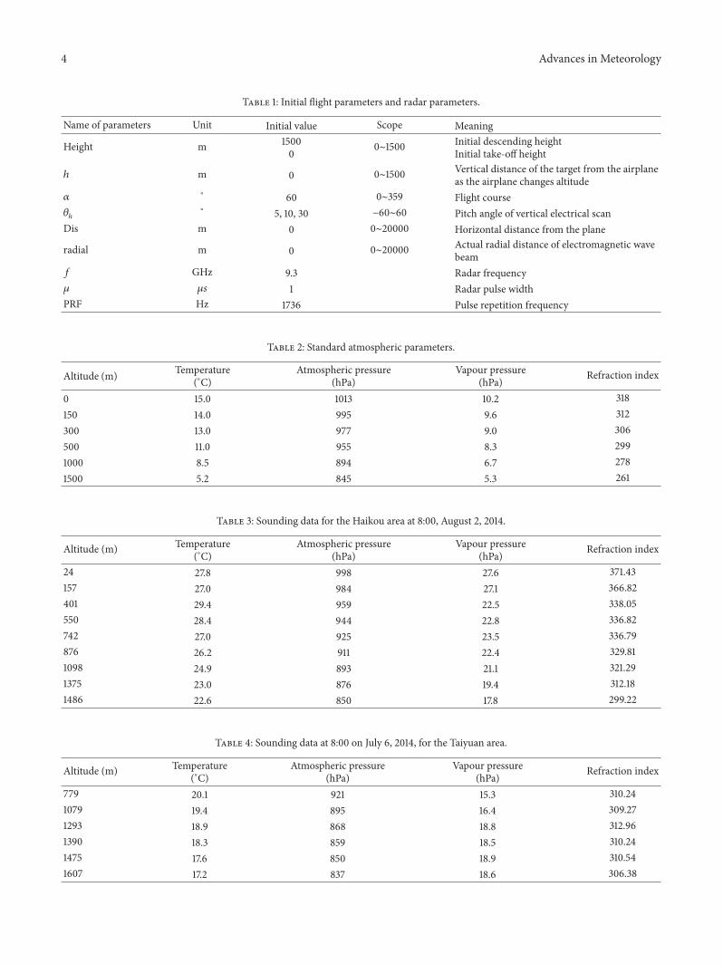
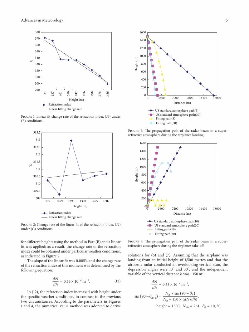
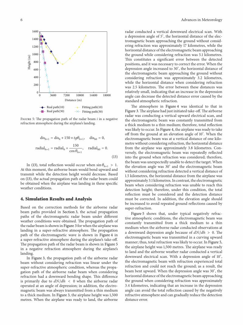
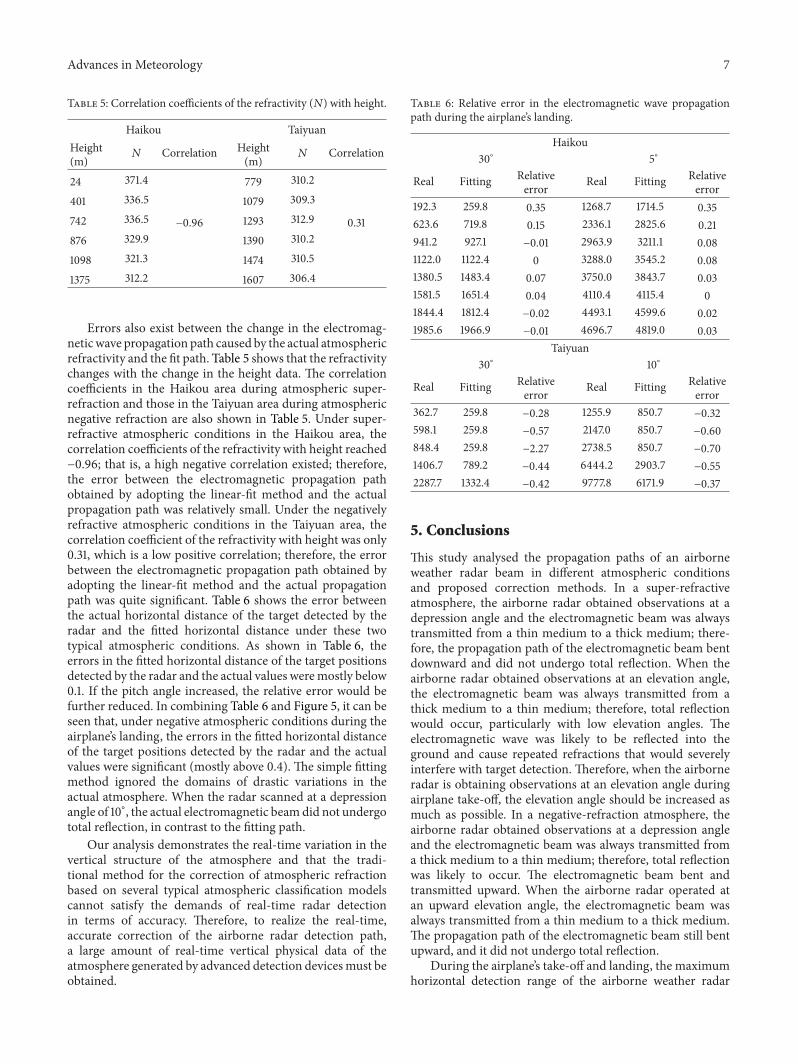