research article hierarchical velocity control based on...
TRANSCRIPT

Research ArticleHierarchical Velocity Control Based on Differential Flatness fora DC/DC Buck Converter-DC Motor System
R. Silva-Ortigoza,1 C. Márquez-Sánchez,1 F. Carrizosa-Corral,2 M. Antonio-Cruz,1
J. M. Alba-Martínez,1,3 and G. Saldaña-González4
1 Instituto Politecnico Nacional, CIDETEC, Area de Mecatronica, Unidad Profesional Adolfo Lopez Mateos,07700 Mexico, DF, Mexico
2 Instituto Tecnologico de Culiacan, Departamento de Metal-Mecanica, 80220 Culiacan, SIN, Mexico3 DGETI-SEP, Centro Nacional de Actualizacion Docente, Area de Control, 13420 Mexico, DF, Mexico4Universidad Tecnologica de Puebla, Division de Mecatronica, 72300 Puebla, PUE, Mexico
Correspondence should be addressed to R. Silva-Ortigoza; [email protected]
Received 18 February 2014; Accepted 29 March 2014; Published 24 April 2014
Academic Editor: Her-Terng Yau
Copyright © 2014 R. Silva-Ortigoza et al. This is an open access article distributed under the Creative Commons AttributionLicense, which permits unrestricted use, distribution, and reproduction in any medium, provided the original work is properlycited.
This paper presents a hierarchical controller that carries out the angular velocity trajectory tracking task for a DC motor driven bya DC/DC Buck converter. The high level control is related to the DC motor and the low level control is dedicated to the DC/DCBuck converter; both controls are designed via differential flatness. The high level control provides a desired voltage profile for theDC motor to achieve the tracking of a desired angular velocity trajectory. Then, a low level control is designed to ensure that theoutput voltage of the DC/DC Buck converter tracks the voltage profile imposed by the high level control. In order to experimentallyverify the hierarchical controller performance, aDS1104 electronic board fromdSPACEandMatlab-Simulink are used.The switchedimplementation of the hierarchical average controller is accomplished bymeans of pulse widthmodulation. Experimental results ofthe hierarchical controller for the velocity trajectory tracking task show good performance and robustness against the uncertaintiesassociated with different system parameters.
1. Introduction
DC machines are extensively used in many industrial appli-cations, such as servo control and traction tasks, due to theireffectiveness, robustness, and the traditional relative ease inthe devising of appropriate feedback control schemes [1].However, when starting DC motors, it is possible to observeabrupt transient problems in the armature circuit, such asvariations in the voltage, current, and angular velocity of themotor shaft. Moreover, the usual method of applying PWMsignals directly as themotor armature voltage presents similarundesired issues in its dynamic behavior [2]. Such drawbackscan be addressed by using DC/DC power converters. Theseconverters allow the smooth start of a DC motor by applyingthe required voltage in accordance with the demanded task,which is generally the tracking of either a desired angularvelocity or an angular position trajectory. In the particular
case of the DC/DC Buck converter, its two energy storingelements reduce the noisy shape caused by the hard switchingof the PWM. For these reasons, in order to regulate theangular velocity of the DC/DC Buck converter-DC motorsystem, different controllers have been designed.
Lyshevski in [1] proposed fourth-order mathematicalmodels for some combinations of DC/DC power convertersand a DC motor. Additionally, Lyshevski designed PI con-trollers for the direct regulation of the motor shaft speed.In contrast to this previous work, Linares-Flores and Sira-Ramırez presented in [3–5] the design of smooth angularvelocity controllers for a DC motor powered by a DC/DCBuck converter. An average smooth starter, based on dif-ferential flatness, for the velocity regulation of a DC motorpowered via a DC/DC Buck converter was presented in [3].There, the motor armature inductance and the convertercapacitor current are considered as negligible; therefore a
Hindawi Publishing CorporationMathematical Problems in EngineeringVolume 2014, Article ID 912815, 12 pageshttp://dx.doi.org/10.1155/2014/912815

2 Mathematical Problems in Engineering
second-order model is used to design the controller. Linares-Flores and Sira-Ramırez [4] introduced aGPI average controllaw for the angular velocity trajectory tracking task using theflatness of the combined system. To this end, they employedthe mathematical model obtained in [3]. Likewise, for thissame system and task, based on a fourth-order model, thedesign of a dynamic output feedback controller via the energyshaping and damping injection method was presented in[5]. In the works of Linares-Flores and Sira-Ramırez [3–5],the effectiveness of the proposed controllers was verified bynumerical simulations. Antritter et al. in [2] and Linares-Flores in [6] (partially published in [7]), concerning theangular velocity trajectory tracking task in DC/DC Buckconverter-DC motor systems, presented a flatness-basedaverage controller, which was experimentally implementedby employing a PWM through acquisition cards. Howeverthere was no experimental validation for different parametricuncertainties of the system. Also, for this system, El Fadiland Giri in [8] elaborated an average controller via thebackstepping approach and designed both nonadaptive andadaptive versions.They show, through numerical simulationsthat include a PWM, that the adaptive version performs wellagainst uncertain load torque changes. Nevertheless, neithersmooth references nor any parametric uncertainties of eitherthe converter and the motor were considered. On the otherhand, a comparative evaluation, via numerical simulations, ofthe performance of several control strategies such as PI, PI +Fuzzy Logic, and LQR for angular velocity trajectory trackingof a DC motor powered by a DC/DC Buck converter waspresented by Ahmad et al. in [9]. Similarly, Sureshkumar andGaneshkumar in [10], via numerical simulations, comparedthe performance of both PI and backstepping controllersrelated to angular velocity regulation of the aforementionedsystem. More recently, Sira-Ramırez and Oliver-Salazar in[11] proposed a robust control based on an active disturbancerejection control and differential flatness, considering thepresence of an unknown time-varying load, for two differentcombinations of DC/DC Buck converters and DC motors.Numerical simulations showed the robustness of that tech-nique for the angular velocity control of the motor shaft. Inthe study of Silva-Ortigoza et al. [12] a two-stage controllerbased on differential flatness for the sensorless velocitycontrol of a DC motor driven by a DC/DC Buck converterhas been presented. It has been shown via realistic simula-tions, which included a Σ-Δ-modulator, that the proposedcontrol scheme effectively provides robustness to the trackingperformance in the presence of uncertainties associated withthe system parameters. Finally, Silva-Ortigoza et al. in [13]presented a smooth starter, via a DC/DC Buck converter,for the angular velocity trajectory tracking task of a DCmotor. They designed a hierarchical controller that includesa control based on differential flatness for the DC motor anda cascade control, designed through a sliding mode controland a PI control, for the Buck converter. The robustness ofthe hierarchical controller was shown via experimental tests.Additionally, important contributions about the integrationof other DC/DC power converters with DC motors werepresented in [6, 14–16].
Based on the literature review previously presented,the problem of controlling the DC/DC Buck converter-DCmotor combined system has been addressed by twomethods:(i) by using a fourth-order model that leads to very longcontrol laws, which are generally complex to implement and(ii) by using a second-order model, achieved by neglectingparameters or states of the system, which is impractical forlow and medium power applications (as stated in [8]). Inthis paper, as a variation from method (i), controls for themotor and the converter models are considered separately(see [12, 13]). Additionally, the literature reviewed shows that,generally, experimental validation has not been performedwhen there aremultiple parameter uncertainties for either theconverter or the motor.
Motivated by the hierarchical control approach usedin mobile robotics [17], where the equation that governsthe high level control imposes the desired profile to befollowed by a low level control through an inner control loop(e.g., [18–20]), in this paper, as a continuation of [12], theexperimental validation of a hierarchical controller for theangular velocity trajectory tracking task of a DC/DC Buckconverter-DC motor system is presented. In particular, thiswork presents a flatness-based control. Furthermore, sincethe proposed hierarchical controller approach is based on thesystem average model, it uses a PWM implementation. Theperformance of the hierarchical controller strategy is verifiedexperimentally, showing robustness under severe parameteruncertainties.
This paper is structured as follows. The design of thecontrol laws associated with the hierarchical controller forthe DC/DC Buck converter-DC motor system is presentedin Section 2. With the purpose of evaluating its performance,Section 3 presents the experimental results. Finally, conclu-sions are drawn in Section 4.
2. Hierarchical Velocity Control for theDC/DC Buck Converter-DC Motor System
This section presents a solution to the angular velocitytrajectory tracking problem for the DC/DC Buck converter-DC motor system via a hierarchical controller. The maincharacteristics of this controller are as follows.
(1) A high level control: this control, based on differentialflatness, provides a desired voltage profile that com-mands the DC motor to achieve the angular velocitytrajectory tracking task.
(2) A low level control: this control, also based ondifferential flatness, is designed to ensure that theDC/DC Buck converter voltage tracks the desiredvoltage profile generated by the high level control.
(3) Similar to the approach used in mobile robotics (e.g.,[18–20]), the controls described in the items (1) and(2) are interconnected to solve the angular velocitytrajectory tracking problem.
The DC/DC Buck converter-DC motor system is shown inFigure 1.
Mathematical Problems in Engineering 3
Q L
E u
D
i
C R
+
La Ra
ia
𝜗𝜔
−
DC/DC Buck converter DC motor
+
−
𝜐
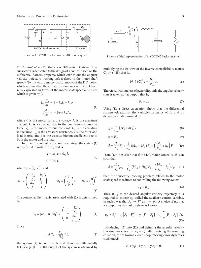
Figure 1: DC/DC Buck converter-DC motor system.
2.1. Control of a DC Motor via Differential Flatness. Thissubsection is dedicated to the design of a control based on thedifferential flatness property, which carries out the angularvelocity trajectory tracking task (related to the motor shaftspeed). To this end, a mathematical model of the DC motor,which assumes that the armature inductance is different fromzero, expressed in terms of the motor shaft speed 𝜔 is used,which is given by [21]
𝐿𝑎
𝑑𝑖𝑎
𝑑𝑡= 𝜗 − 𝑅
𝑎𝑖𝑎− 𝑘𝑒𝜔,
𝐽𝑑𝜔
𝑑𝑡= − 𝑏𝜔 + 𝑘
𝑚𝑖𝑎,
(1)
where 𝜗 is the motor armature voltage, 𝑖𝑎is the armature
current, 𝑘𝑒is a constant due to the counter-electromotive
force, 𝑘𝑚is the motor torque constant, 𝐿
𝑎is the armature
inductance, 𝑅𝑎is the armature resistance, 𝐽 is the rotor and
load inertia, and 𝑏 is the viscous friction coefficient due toboth the motor and the load.
In order to synthesize the control strategy, the system (1)is expressed in matrix form; that is,
𝜒 = A1𝜒 +B
1𝜗,
𝑦1= C1𝜒,
(2)
where 𝜒 = (𝑖𝑎𝜔)𝑇 and
A1= (
−𝑅𝑎
𝐿𝑎
−𝑘𝑒
𝐿𝑎
𝑘𝑚
𝐽−𝑏
𝐽
) ; B1= (
1
𝐿𝑎
0
) ; C1= (0
1)
𝑇
.
(3)
The controllability matrix associated with (2) is determinedby
C1= (B1A1B1) = (
1
𝐿𝑎
−𝑅𝑎
𝐿2𝑎
0𝑘𝑚
𝐽𝐿𝑎
). (4)
Since
detC1=𝑘𝑚
𝐽𝐿2𝑎
= 0, (5)
the system (2) is controllable and therefore differentiallyflat (see [21]). The flat output of the system is obtained by
−
+
E
u = 1
S i L
C R
−
+
u=0 𝜐
Figure 2: Ideal representation of the DC/DC Buck converter.
multiplying the last row of the inverse controllability matrixC1by 𝜒 [21]; that is,
(0 1)C−11𝜒 =𝐽𝐿𝑎
𝑘𝑚
𝜔. (6)
Therefore, without loss of generality, only the angular velocitystate is taken as flat output; that is,
𝐹1= 𝜔. (7)
Using (1), a direct calculation shows that the differentialparameterization of the variables in terms of 𝐹
1and its
derivatives is determined by
𝑖𝑎=1
𝑘𝑚
(𝐽��1+ 𝑏𝐹1) , (8)
𝜔 = 𝐹1, (9)
𝜗 =𝐽𝐿𝑎
𝑘𝑚
��1+1
𝑘𝑚
(𝑏𝐿𝑎+ 𝐽𝑅𝑎) ��1+ (𝑏𝑅𝑎
𝑘𝑚
+ 𝑘𝑒)𝐹1. (10)
From (10), it is clear that if the DC motor control is chosensuch that
𝜗 =𝐽𝐿𝑎
𝑘𝑚
𝜇𝑚+1
𝑘𝑚
(𝑏𝐿𝑎+ 𝐽𝑅𝑎) ��1+ (𝑏𝑅𝑎
𝑘𝑚
+ 𝑘𝑒)𝐹1, (11)
then the trajectory tracking problem related to the motorshaft speed is reduced to controlling the following system:
��1= 𝜇𝑚. (12)
Thus, if 𝐹∗1is the desired angular velocity trajectory, it is
required to choose 𝜇𝑚, called the auxiliary control variable,
in such a way that 𝐹1→ 𝐹∗
1as 𝑡 → ∞. A choice of 𝜇
𝑚that
accomplishes this task is given as follows:
𝜇𝑚= ��∗
1− 𝛾2[��1− ��∗
1] − 𝛾1[𝐹1− 𝐹∗
1] − 𝛾0∫
𝑡
0
[𝐹1− 𝐹∗
1] 𝑑𝜏.
(13)
Introducing (13) into (12) and defining the angular velocitytracking error as 𝑒
1= 𝐹1− 𝐹∗
1, after deriving the resulting
equation, the following closed-loop tracking error dynamicsis obtained:
𝑒1+ 𝛾2𝑒1+ 𝛾1𝑒1+ 𝛾0𝑒1= 0, (14)

4 Mathematical Problems in Engineering
Figure 3: Block diagram of the hierarchical controller.
MU
R840
NTE2984
i
L
u
E
+
+
−
−
C R
GNM5440EDC motor
E6B2-CWZ6Cencoder
𝜃
P5200
volta
gedi
ffere
ntia
l pr
obe
ia
La Ra
𝜃
DS1104
PWMu
d
dt
ADC
Incrementalencoder unit
NOTu Hierarchical
controller
𝜔
2
3
6
5
78
5V
NTE
3087
u330Ω
330Ω
G
D S
S
G
𝜐
𝜐
uav
Figure 4: Block diagram of the connections.
which has the following associated characteristic polynomial:
𝑝1(𝑠) = 𝑠
3
+ 𝛾2𝑠2
+ 𝛾1𝑠 + 𝛾0. (15)
Thus, in order to obtain that 𝑒1→ 0 as 𝑡 → ∞, that is,
𝐹1→ 𝐹∗
1, it is required that (15) be a Hurwitz polynomial.
Based on the following Hurwitz polynomial:
𝑝1𝑑(𝑠) = (𝑠 + 𝑎
1) (𝑠2
+ 2𝜁1𝜔𝑛1𝑠 + 𝜔2
𝑛1) , (16)
where 𝑎1> 0, 𝜔
𝑛1> 0, and 𝜁
1> 0, by equating (15) with (16)
it is found that the parameters 𝛾2, 𝛾1, and 𝛾
0are determined
by
𝛾2= 𝑎1+ 2𝜁1𝜔𝑛1; 𝛾
1= 2𝜁1𝜔𝑛1𝑎1+ 𝜔2
𝑛1; 𝛾
0= 𝑎1𝜔2
𝑛1.
(17)
In conclusion, the obtained control expression is
𝜗 =𝐽𝐿𝑎
𝑘𝑚
𝜇𝑚+1
𝑘𝑚
(𝑏𝐿𝑎+ 𝐽𝑅𝑎) �� + (
𝑏𝑅𝑎
𝑘𝑚
+ 𝑘𝑒)𝜔, (18)
where
𝜇𝑚= ��∗
− 𝛾2(�� − ��
∗
) − 𝛾1(𝜔 − 𝜔
∗
) − 𝛾0∫
𝑡
0
(𝜔 − 𝜔∗
) 𝑑𝜏,
(19)
such that 𝜔 → 𝜔∗ as 𝑡 → ∞.
2.2. Control of a DC/DC Buck Converter Based on DifferentialFlatness. From the results obtained, it can be observed that

Mathematical Problems in Engineering 5
the voltage profile 𝜗 required for the DC motor to follow adesired angular velocity trajectory 𝜔∗ is determined by (18).Consequently, since this voltage is produced by a DC/DCBuck converter, a control is needed for this converter toreproduce the desired voltage profile 𝜗.
A simplified electronic circuit of a DC/DC Buck con-verter is shown in Figure 2.The corresponding averagemodelfor this switched converter is given by [22]
𝐿𝑑𝑖
𝑑𝑡= − 𝜐 + 𝐸𝑢av,
𝐶𝑑𝜐
𝑑𝑡= 𝑖 −
𝜐
𝑅,
(20)
where 𝑖 is the current across the inductor and 𝜐 is the outputcapacitor voltage. The control input 𝑢av is the average signal,bounded by the interval [0, 1], associated with the switchposition function. The system parameters are constituted by𝐿, the inductance of the input circuit;𝐶, the capacitance of theoutput filter; and 𝑅, the output load resistance. The externalvoltage source has the constant value 𝐸.
In order to synthesize a control for the DC/DC Buckconverter, the system (20) is expressed by
�� = A2𝑥 +B
2𝑢av,
𝑦2= C2𝑥,
(21)
where 𝑥 = (𝑖 𝜐)𝑇 and
A2= (
0 −1
𝐿1
𝐶−1
𝑅𝐶
) ; B2= (
𝐸
𝐿
0) ; C
2= (0
1)
𝑇
.
(22)
Thus, the system controllability matrix (21) is
C2= (B2A2B2) = (
𝐸
𝐿0
0𝐸
𝐿𝐶
) , (23)
which is clearly full range, as
detC2=𝐸2
𝐿2𝐶= 0. (24)
Hence, the system (21) is controllable and therefore differen-tially flat (see [21]). Then, the flat output of the converter is
𝐹2= (0 1)C−1
2𝑥 =𝐿𝐶
𝐸𝜐. (25)
Therefore, without loss of generality, the voltage of theDC/DC Buck converter is taken as a flat output; that is,
𝐹2= 𝜐. (26)
Thus, the system state variables 𝑥, and the control input 𝑢av,can be written in terms of 𝐹
2and its derivatives. Using (20),
Figure 5: Experimental prototype.
the following differential parameterization of the system isobtained:
𝑖 = 𝐶��2+1
𝑅𝐹2, (27)
𝜐 = 𝐹2, (28)
𝑢av =𝐿𝐶
𝐸��2+𝐿
𝑅𝐸��2+1
𝐸𝐹2. (29)
From (29), it is evident that if 𝑢av is chosen to be
𝑢av =𝐿𝐶
𝐸𝜇𝑐+𝐿
𝑅𝐸��2+1
𝐸𝐹2, (30)
then the trajectory tracking task associated with the outputvoltage of the DC/DC Buck converter is simplified to con-trolling the following system:
��2= 𝜇𝑐. (31)
Thus, if 𝐹∗2
is the desired output voltage trajectory, it isnecessary to choose 𝜇
𝑐in such a way that 𝐹
2→ 𝐹
∗
2as
𝑡 → ∞. A choice of 𝜇𝑐that achieves this task is determined
by
𝜇𝑐= ��∗
2− 𝛽2[��2− ��∗
2] − 𝛽1[𝐹2− 𝐹∗
2] − 𝛽0∫
𝑡
0
[𝐹2− 𝐹∗
2] 𝑑𝜏.
(32)
In order to show that a 𝜇𝑐given by (32) achieves the objective,
it is substituted into (31) and the resultant integro-differentialexpression is differentiated once with respect to time. Then,defining the voltage tracking error to be 𝑒
2= 𝐹2− 𝐹∗
2, the
following closed-loop tracking error dynamics can be found:
𝑒2+ 𝛽2𝑒2+ 𝛽1𝑒2+ 𝛽0𝑒2= 0. (33)
The characteristic polynomial associated with (33) is
𝑝2(𝑠) = 𝑠
3
+ 𝛽2𝑠2
+ 𝛽1𝑠 + 𝛽0. (34)
The values of the design parameters 𝛽2, 𝛽1, and 𝛽
0are chosen
so that the closed-loop characteristic polynomial (34) has allof its roots in the left half of the complex plane, that is, in

6 Mathematical Problems in Engineering
0 1 2 3 4 5 6
0
5
10
15
20(rad/s)
𝜔
𝜔∗
t (s)0 1 2 3 4 5 6
0
5
10
(V)
t (s)
𝜗
0 1 2 3 4 5 6
0
0.5
1
1.5
(A)
t (s)
i
0 1 2 3 4 5 6
0
0.1
0.2
0.3
t (s)
𝜐
uav
Figure 6: Experimental results with uncertainties in 𝑅.
order to arrange that 𝑒2→ 0 as 𝑡 → ∞. Thus, the controller
parameters of the converter were chosen so as to achieve thefollowing desired closed-loop characteristic polynomial:
𝑝2𝑑(𝑠) = (𝑠 + 𝑎
2) (𝑠2
+ 2𝜁2𝜔𝑛2𝑠 + 𝜔2
𝑛2) , (35)
taking into account that 𝑎2> 0, 𝜔
𝑛2> 0, and 𝜁
2> 0. Hence,
the gains of the flatness-based control are given by
𝛽2= 𝑎2+ 2𝜁2𝜔𝑛2; 𝛽1= 2𝜁2𝜔𝑛2𝑎2+ 𝜔2
𝑛2; 𝛽0= 𝑎2𝜔2
𝑛2.
(36)In conclusion, the control expression obtained is
𝑢av =𝐿𝐶
𝐸𝜇𝑐+𝐿
𝑅𝐸𝜐 +1
𝐸𝜐, (37)
where
𝜇𝑐= 𝜐∗
− 𝛽2( 𝜐 − 𝜐
∗
) − 𝛽1(𝜐 − 𝜐
∗
) − 𝛽0∫
𝑡
0
(𝜐 − 𝜐∗
) 𝑑𝜏,
(38)
so that 𝜐 → 𝜐∗ as 𝑡 → ∞.
2.3. Hierarchical Velocity Controller. Similar to the hierarchi-cal control approach used inmobile robotics, the two controlsgiven by (18) and (37) are now interconnected to provide asolution to the angular velocity trajectory tracking problemof the DC motor driven by a DC/DC Buck converter. Thus,in Figure 3, a block diagram shows the integration of thehierarchical controller scheme proposed in this research.
Starting from the mathematical model of the DC motor,
𝐿𝑎
𝑑𝑖𝑎
𝑑𝑡= 𝜗 − 𝑅
𝑎𝑖𝑎− 𝑘𝑒𝜔,
𝐽𝑑𝜔
𝑑𝑡= − 𝑏𝜔 + 𝑘
𝑚𝑖𝑎,
(39)
it was found that the control associated with this model isdetermined by (18) and (19); that is,
𝜗 =𝐽𝐿𝑎
𝑘𝑚
𝜇𝑚+1
𝑘𝑚
(𝑏𝐿𝑎+ 𝐽𝑅𝑎) �� + (
𝑏𝑅𝑎
𝑘𝑚
+ 𝑘𝑒)𝜔, (40)

Mathematical Problems in Engineering 7
(rad/s)
𝜔
𝜔∗
t (s)0 1 2 3 4 5 6
0
5
10
15
20
(V)
t (s)
𝜗
0 1 2 3 4 5 6
0
4
8
12
(A)
t (s)
i
0 1 2 3 4 5 6
0
0.3
0.6
0.9
t (s)0 1 2 3 4 5 6
0
0.1
0.2
0.3
0.4
𝜐
uav
Figure 7: Experimental results due to 𝐸 uncertainties.
where
𝜇𝑚= ��∗
− 𝛾2(�� − ��
∗
) − 𝛾1(𝜔 − 𝜔
∗
) − 𝛾0∫
𝑡
0
(𝜔 − 𝜔∗
) 𝑑𝜏.
(41)
As the DCmotor is connected to the DC/DC Buck converter,whose mathematical model is given by
𝐿𝑑𝑖
𝑑𝑡= − 𝜐 + 𝐸𝑢av,
𝐶𝑑𝜐
𝑑𝑡= 𝑖 −
𝜐
𝑅,
(42)
the control associated with the converter was found to bedetermined by (37) and (38); that is,
𝑢av =𝐿𝐶
𝐸𝜇𝑐+𝐿
𝑅𝐸𝜐 +1
𝐸𝜐, (43)
where
𝜇𝑐= 𝜐∗
− 𝛽2( 𝜐 − 𝜐
∗
) − 𝛽1(𝜐 − 𝜐
∗
) − 𝛽0∫
𝑡
0
(𝜐 − 𝜐∗
) 𝑑𝜏,
𝜐∗
= 𝜗.
(44)
Thus, the desired voltage trajectory 𝜐∗ for the DC/DC Buckconverter is determined by the voltage profile 𝜗, which isobtained by theDCmotor control.This allows accomplishingthe tracking of the desired angular velocity trajectory 𝜔∗.
3. Experimental Results
In this section, the experimental results for the closed-loopsystem are presented in order to evaluate the performance ofthe proposed hierarchical controller.

8 Mathematical Problems in Engineering
(rad/s)
𝜔
𝜔∗
t (s)0 1 2 3 4 5 6
0
5
10
15
20
(V)
t (s)
𝜗
0 1 2 3 4 5 6
0
4
8
12
(A)
t (s)
i
00
1 2 3 4 5 6
0.25
0.5
0.75
t (s)0 1 2 3 4 5 6
0
0.1
0.2
0.3
𝜐
uav
Figure 8: Experimental results from changes in 𝐿 and 𝐶.
The hierarchical controller implementation requires themeasurement of 𝜐 and 𝜔, which are associated with thevoltage of the converter capacitor and the motor shaft speed,respectively.Thus, 𝜐 ismeasured by a Tektronix P5200 voltagedifferential probe and𝜔 is estimated by an incremental rotaryencoder Omron E6B2-CWZ6C. The hardware implementa-tion of the hierarchical controller is performed via a DS1104electronic board from dSPACE, using Matlab-Simulink. InFigure 4, a block diagram shows the connections of theDC/DC Buck converter, the DC motor, the hierarchicalcontroller, and the electronic circuit employed to isolate theDS1104 board from the converter. It is worth mentioning thatthe DS1104 board produces the complement of 𝑢, that is, 𝑢,due to the fact that the isolation circuit inverts the logicalinput. A picture of the prototype is shown in Figure 5.
Since the controller cannot appropriately command theDC/DC Buck converter switch position, as it was designed
based on its average model, a PWM is used for this imple-mentation. The PWM frequency is set to a switching rate of50 kHz by using one of the DS1104 output pins.
The DC motor used in these experiments is an EngelGNM5440E (1600 rpm@24V and a gearbox G3.1 with a14.5 : 1 reduction ratio), whose parameters are
𝐿𝑎= 2.219mH, 𝑘
𝑒= 120.1mN⋅m/A,
𝑅𝑎= 965mΩ, 𝑘
𝑚= 120.1mV⋅s/rad,
𝑏 = 129.6mN⋅m⋅s, 𝐽 = 118.2mkg⋅m2.
(45)
The parameters of the DC/DC Buck converter are
𝐿 = 4.94mH, 𝐶 = 224.4 𝜇F, 𝑅 = 28Ω, 𝐸 = 52V.(46)

Mathematical Problems in Engineering 9
(rad/s)
𝜔
𝜔∗
t (s)0 1 2 3 4 5 6
0
5
10
15
20
(V)
t (s)
𝜗
0 1 2 3 4 5 6
0
4
8
12
(A)
t (s)
i
0 1 2 3 4 5 60
0.2
0.4
0.6
0.8
t (s)0 1 2 3 4 5 6
0
0.2
0.4
𝜐
uav
Figure 9: Experimental results related to 𝑏𝑚.
The results are obtained from the particular case wherethe desired angular velocity trajectory is defined by
𝜔∗
(𝑡) = 1 + 2.5𝜋 [(1 − 𝑒−2𝑡3
) (1 + sin 5𝑡)] . (47)
All experiments were performed at a sampling time of 𝑇 =10 𝜇s. The parameters associated with the controller gains ofthe motor (𝛾
2, 𝛾1, 𝛾0) and of the converter (𝛽
2, 𝛽1, 𝛽0), which
are determined by (17) and (36), respectively, were chosen tobe
𝑎1= 215, 𝜁
1= 0.707, 𝜔
𝑛1= 155.40,
𝑎2= 13, 𝜁
2= 0.580, 𝜔
𝑛2= 1150.
(48)
The first experiment is meant to highlight the effective-ness of the hierarchical controller design. It is performed byapplying drastic load changes determined by
𝑅𝑚=
{{{{
{{{{
{
𝑅 for 𝑡 < 2.6 s50%𝑅 = 14Ω for 2.6 ≤ 𝑡 < 3.8 s,𝑅 for 3.8 ≤ 𝑡 < 5 s,21%𝑅 ≈ 5.9Ω for 𝑡 ≥ 5 s.
(49)
The corresponding results are shown in Figure 6. It is clearthat the mechanical variable 𝜔 follows the desired trajectory𝜔∗, which shows the effectiveness of the designed hierarchical
controller under abrupt changes of 𝑅. In Figure 6, it canbe observed that smaller values than the nominal valueof 𝑅 cause a significant increase of 𝑖. On the other hand,changes of𝑅 higher than 100% from its nominal value are not

10 Mathematical Problems in Engineering
(rad/s)
𝜔
𝜔∗
t (s)0 1 2 3 4 5 6
0
5
10
15
20
(V)
t (s)
𝜗
0 1 2 3 4 5 6
0
4
8
12
(A)
t (s)
i
0 1 2 3 4 5 60
0.2
0.4
0.6
0.8
t (s)0 1 2 3 4 5 6
0
0.1
0.2
0.3
𝜐
uav
Figure 10: Experimental results for 𝐽𝑚.
considered, as the current would decrease, implying that lessis demanded of the system.
The proposed hierarchical controller is also experimen-tally robust with respect to themain power source, which canbe observed by setting the following experimental changes:
𝐸𝑚=
{{
{{
{
𝐸 for 𝑡 < 2.6 s,57.7%𝐸 = 30V for 2.6 ≤ 𝑡 < 3.8 s,𝐸 for 𝑡 ≥ 3.8 s.
(50)
Figure 7 shows the experimental behavior of the mechanicaland electrical variables of the system when abrupt changesoccur in𝐸. It can be observed that the trajectory tracking taskis successfully performed, since𝜔 → 𝜔∗. On the other hand,if the primary power supply were to change to a value higherthan 𝐸, it would be observed that 𝑢av → 0, implying that less
is demanded of the system; therefore such changes were notexecuted.
Moreover, Figure 8 shows that the trajectory tracking taskis successfully performed according to the design goal, evenwhen the system has significant abrupt changes in 𝐿 and 𝐶.The experimental changes proposed in this work are definedby
𝐿𝑚=
{{
{{
{
𝐿 for 𝑡 < 2.6 s,200%𝐿 = 9.88mH for 2.6 ≤ 𝑡 < 3.8 s,𝐿 for 𝑡 ≥ 3.8 s.
𝐶𝑚=
{{{{
{{{{
{
𝐶 for 𝑡 < 2.6 s,150%𝐶 ≈ 334.4 𝜇F for 2.6 ≤ 𝑡 < 3.8 s,𝐶 for 3.8 ≤ 𝑡 < 5 s,50%𝐶 = 112.2 𝜇F for 𝑡 ≥ 5 s.
(51)

Mathematical Problems in Engineering 11
Likewise, experimental emulation of the viscous frictioncoefficient was tested in the system and the results are shownin Figure 9. The proposed changes are
𝑏𝑚=
{{{{
{{{{
{
𝑏 for 𝑡 < 2.6 s500%𝑏 for 2.6 ≤ 𝑡 < 3.8 s,𝑏 for 3.8 ≤ 𝑡 < 5 s,800%𝑏 for 𝑡 ≥ 5 s.
(52)
Finally, Figure 10 presents the results when the motorinertia is drastically changed in accordancewith the followingexpression:
𝐽𝑚=
{{
{{
{
𝐽 for 𝑡 < 2.6 s,141.7%𝐽 for 2.6 ≤ 𝑡 < 3.8 s,𝐽 for 𝑡 ≥ 3.8 s.
(53)
4. Conclusions
Motivated by the hierarchical control approach applied inmobile robotics, this paper presented the experimental val-idation of a hierarchical controller, based on differentialflatness, for the angular velocity trajectory tracking problemof a DC/DC Buck converter-DC motor system. The hier-archical controller was composed of two controls: the firstone was designed for the DC motor and the second one wasdedicated to the DC/DCBuck converter.Then, these controlswere interconnected emulating the approach used in mobilerobotics.
According to the experimental results herein reported,here, the angular velocity trajectory tracking task, associatedwith a DC motor driven by a DC/DC Buck converter, wassuccessfully achieved by the proposed hierarchical controller.Moreover, it showed robustness against the uncertaintiesassociated with several system parameters. Finally, it is worthmentioning that, in practice, these kinds of changes hap-pen neither simultaneously nor in such extreme conditionswith respect to their nominal values. Nevertheless, theseexperiments were meant to validate the effectiveness of theproposed controller, thus presenting a glimpse of its possiblefuture industrial applications.
Conflict of Interests
The authors declare that the research was conducted inthe absence of any commercial, financial, or personal rela-tionships that could be construed as a potential conflict ofinterests.
Acknowledgments
R. Silva-Ortigoza acknowledges financial support from Sec-retarıa de Investigacion y Posgrado del Instituto PolitecnicoNacional (SIP-IPN), SNI-Mexico, and the IPN programsEDI and COFAA. The work of C. Marquez-Sanchez andM. Antonio-Cruz was supported by CONACYT-Mexicoand PIFI scholarships. G. Saldana-Gonzalez acknowledgesthe Fondo Mixto CONACYT, since the publication of this
work was partially supported with funds from the FondoMixto de Fomento a la Investigacion Cientıfica y TecnologicaCONACYT-Gobierno del Estado de Puebla.
References
[1] S. E. Lyshevski, Electromechanical Systems, Electric Machines,and Applied Mechatronics, CRC Press, Boca Raton, Fla, USA,1999.
[2] F. Antritter, P. Maurer, and J. Reger, “Flatness based control ofa Buck-converter driven DC motor,” in Proceedings of the 4thIFAC Symposium on Mechatronic Systems, pp. 36–41, Ruprecht-Karls-University, Heidelberg, Germany, September 2006.
[3] J. Linares-Flores and H. Sira-Ramırez, “A smooth starter fora DC machine: a flatness based approach,” in Proceedings ofthe 1st International Conference on Electrical and ElectronicsEngineering, pp. 589–594, Acapulco, Mexico, September 2004.
[4] J. Linares-Flores and H. Sira-Ramırez, “Sliding mode-deltamodulation GPI control of a DC motor through a Buckconverter,” inProceedings of the 2nd IFAC Symposiumon System,Structure and Control, pp. 405–409, Oaxaca, Mexico, December2004.
[5] J. Linares-Flores and H. Sira-Ramırez, “DC motor velocitycontrol through a DC-to-DC power converter,” in Proceedingsof the 43rd IEEE Conference on Decision and Control, pp. 5297–5302, Atlantis, The Bahamas, December 2004.
[6] J. Linares-Flores, Control suave de velocidad de motores deCD mediante convertidores de potencia CD/CD [Ph.D. the-sis], Seccion de Mecatronica del Departamento de IngenierıaElectrica del CINVESTAV-IPN, Mexico City, Mexico, 2006.
[7] J. Linares-Flores, A. Orantes-Molina, and A. Antonio-Garcıa,“Arranque suave para un motor de CD a traves de un conver-tidor reductorCDCD,” Ingenierıa Investigacien y Tecnologıa, vol.12, no. 2, pp. 137–148, 2011.
[8] H. El Fadil and F. Giri, “Accounting of Dc-Dc power converterdynamics inDCmotor velocity adaptive control,” inProceedingsof the IEEE International Conference onControl Applications, pp.3157–3162, Munich, Germany, October 2006.
[9] M. A. Ahmad, R. M. T. Raja Ismail, and M. S. Ramli, “Controlstrategy of buck converter driven dc motor: a comparativeassessment,” Australian Journal of Basic and Applied Sciences,vol. 4, no. 10, pp. 4893–4903, 2010.
[10] R. Sureshkumar and S. Ganeshkumar, “Comparative study ofproportional integral and backstepping controller for buckconverter,” in Proceedings of the International Conference onEmerging Trends in Electrical and Computer Technology, pp.375–379, Tamil Nadu, India, March 2011.
[11] H. Sira-Ramırez and M. A. Oliver-Salazar, “On the robustcontrol of Buck-converter DC-motor combinations,” IEEETransactions on Power Electronics, vol. 28, no. 8, pp. 3912–3922,2013.
[12] R. Silva-Ortigoza, J. R. Garcıa-Sanchez, J. M. Alba-Martınez etal., “Two-stage control design of a buck converter/DC motorsystem without velocity measurements via a Σ − Δ-modulator,”Mathematical Problems in Engineering, vol. 2013, Article ID929316, 11 pages, 2013.
[13] R. Silva-Ortigoza, V. M. Hernandez-Guzman, M. Antonio-Cruz, and D. Munoz-Carrillo, “DC/DC Buck power converteras a smooth starter for a DC motor based on a hierarchicalcontrol,” IEEE Transactions on Power Electronics, In press.

12 Mathematical Problems in Engineering
[14] J. Linares-Flores, H. Sira-Ramırez, J. Reger, and R. Silva-Ortigoza, “An exact tracking error dynamics passive outputfeedback controller for a Buck-Boost-converter driven DCmotor,” in Proceedings of the 10th IEEE International PowerElectronics Congress, pp. 1–5, Puebla, Mexico, October 2006.
[15] J. Linares-Flores, J. Reger, and H. Sira-Ramirez, “Loadtorque estimation and passivity-based control of a boost-converter/DC-motor combination,” IEEE Transactions onControl Systems Technology, vol. 18, no. 6, pp. 1398–1405, 2010.
[16] V. M. Hernandez-Guzman, R. Silva-Ortigoza, and R. V.Carrillo-Serrano, Control Automatico: Teorıa de Diseno, Con-struccion de Prototipos, Modelado, Identificacion y PruebasExperimentales, Coleccion CIDETEC–IPN, Mexico City, Mex-ico, 2013, http://www.controlautomatico.com.mx/.
[17] R. Silva-Ortigoza, M. Marcelino-Aranda, G. Silva-Ortigoza etal., “Wheeled mobile robots: a review,” IEEE Latin AmericaTransactions, vol. 10, no. 6, pp. 2209–2217, 2012.
[18] A. W. Divelbiss and J. T. Wen, “Trajectory tracking controlof a car-trailer system,” IEEE Transactions on Control SystemsTechnology, vol. 5, no. 3, pp. 269–278, 1997.
[19] R. Silva-Ortigoza, G. Silva-Ortigoza, V. M. Hernandez-Guzman, V. R. Barrientos-Sotelo, J. M. Albarran-Jimenez, andV. M. Silva-Garcıa, “Trajectory tracking in a mobile robotwithout using velocity measurements for control of wheels,”IEEE Latin America Transactions, vol. 6, no. 7, pp. 598–607,2008.
[20] R. Silva-Ortigoza, C. Marquez-Sanchez, M. Marcelino-Arandaet al., “Construction of a WMR for trajectory tracking control:experimental results,” The Scientific World Journal, vol. 2013,Article ID 723645, 17 pages, 2013.
[21] H. Sira-Ramırez and S. K. Agrawal, Differentially Flat Systems,Marcel Dekker, New York, NY, USA, 2004.
[22] H. Sira-Ramırez and R. Silva-Ortigoza, Control Design Tech-niques in Power Electronics Devices, Springer, London, UK,2006.

Submit your manuscripts athttp://www.hindawi.com
Hindawi Publishing Corporationhttp://www.hindawi.com Volume 2014
MathematicsJournal of
Hindawi Publishing Corporationhttp://www.hindawi.com Volume 2014
Mathematical Problems in Engineering
Hindawi Publishing Corporationhttp://www.hindawi.com
Differential EquationsInternational Journal of
Volume 2014
Applied MathematicsJournal of
Hindawi Publishing Corporationhttp://www.hindawi.com Volume 2014
Probability and StatisticsHindawi Publishing Corporationhttp://www.hindawi.com Volume 2014
Journal of
Hindawi Publishing Corporationhttp://www.hindawi.com Volume 2014
Mathematical PhysicsAdvances in
Complex AnalysisJournal of
Hindawi Publishing Corporationhttp://www.hindawi.com Volume 2014
OptimizationJournal of
Hindawi Publishing Corporationhttp://www.hindawi.com Volume 2014
CombinatoricsHindawi Publishing Corporationhttp://www.hindawi.com Volume 2014
International Journal of
Hindawi Publishing Corporationhttp://www.hindawi.com Volume 2014
Operations ResearchAdvances in
Journal of
Hindawi Publishing Corporationhttp://www.hindawi.com Volume 2014
Function Spaces
Abstract and Applied AnalysisHindawi Publishing Corporationhttp://www.hindawi.com Volume 2014
International Journal of Mathematics and Mathematical Sciences
Hindawi Publishing Corporationhttp://www.hindawi.com Volume 2014
The Scientific World JournalHindawi Publishing Corporation http://www.hindawi.com Volume 2014
Hindawi Publishing Corporationhttp://www.hindawi.com Volume 2014
Algebra
Discrete Dynamics in Nature and Society
Hindawi Publishing Corporationhttp://www.hindawi.com Volume 2014
Hindawi Publishing Corporationhttp://www.hindawi.com Volume 2014
Decision SciencesAdvances in
Discrete MathematicsJournal of
Hindawi Publishing Corporationhttp://www.hindawi.com
Volume 2014 Hindawi Publishing Corporationhttp://www.hindawi.com Volume 2014
Stochastic AnalysisInternational Journal of