research article model for charge transport in ...downloads.hindawi.com/archive/2015/745056.pdfmodel...
TRANSCRIPT

Research ArticleModel for Charge Transport in FerroelectricNanocomposite Film
Meng H Lean and Wei-Ping L Chu
QEDone LLC Santa Clara CA 95054 USA
Correspondence should be addressed to Meng H Lean mhleanieeeorg
Received 2 December 2014 Accepted 10 February 2015
Academic Editor Anjanapura V Raghu
Copyright copy 2015 M H Lean and W-P L ChuThis is an open access article distributed under the Creative Commons AttributionLicense which permits unrestricted use distribution and reproduction in anymedium provided the originalwork is properly cited
This paper describes 3D particle-in-cell simulation of charge injection and transport through nanocomposite film comprisedof ferroelectric ceramic nanofillers in an amorphous polymer matrix andor semicrystalline ferroelectric polymer with varyingdegrees of crystallinity The classical electrical double layer model for a monopolar core is extended to represent thenanofillernanocrystallite by replacing it with a dipolar core Charge injection at the electrodes assumes metal-polymer Schottkyemission at low to moderate fields and Fowler-Nordheim tunneling at high fields Injected particles propagate via field-dependentPoole-Frenkel mobility The simulation algorithm uses a boundary integral equation method for solution of the Poisson equationcoupled with a second-order predictor-corrector scheme for robust time integration of the equations of motion The stabilitycriterion of the explicit algorithm conforms to the Courant-Friedrichs-Levy limit assuring robust and rapid convergenceSimulation results for BaTiO
3nanofiller in amorphous polymer matrix and semicrystalline PVDF with varying degrees of
crystallinity indicate that charge transport behavior depends on nanoparticle polarization with antiparallel orientation showingthe highest conduction and therefore the lowest level of charge trapping in the interaction zone Charge attachment to nanofillersand nanocrystallites increases with vol loading or degree of crystallinity and saturates at 30ndash40 vol for the set of simulationparameters
1 Introduction
Nanocomposite films comprising ceramic nanofillers inamorphous polymer matrices are of interest in capacitiveenergy storage for rapid power cycling applications Advan-tages include high energy density low cost lightweightand small footprint Nanocomposite films combine theprocessability and high breakdown field strength of thepolymer with the high dielectric constant of the fillersengineered to an acceptable level of dielectric loss Mostof the increase in the effective dielectric constant comesfrom an increase in the average field in the polymer matrixwith very little of the energy being stored in the highpermittivity phase Large contrast in permittivity betweenthe two phases gives rise to highly inhomogeneous electricfields (E) in the ldquointeraction zonerdquo defined as the interfacialregion that surrounds the nanofillers and interspaces Withinthis region mobility is field-dependent and may also depend
on the physicochemical bonds on the common surfacesMorphology plays an important role in film layers with veryhigh surface-to-volume aspect ratios Highly inhomogeneousfields and structural inhomogeneity generally lead to asignificant reduction in the effective breakdown field strengthof the composite limiting the increase in the energy storagecapacity and energy density So a careful compromise needsto be engineered at the polymer-ceramic interfaces to attain aviable solution [1] Interface engineering attempts to improvethe dispersion of filler in polymer matrix In a well-dispersedcomposite interfaces between the ceramic nanoparticle andpolymer phases create effective electron scattering and trans-port centers thus reducing the breakdown probability More-over well-dispersed ceramic nanoparticles block degradationtree growth and thus increase the long-term breakdownstrength
The polymers currently used as matrices in the dielectricnanocomposites including polyethylenes (PE) poly(methyl
Hindawi Publishing CorporationJournal of PolymersVolume 2015 Article ID 745056 17 pageshttpdxdoiorg1011552015745056
2 Journal of Polymers
methacrylate)s (PMMA) epoxy resins and polyimides (PI)usually possess dielectric permittivities of sim2ndash5 signifi-cantly lower than their inorganic counterparts Poly(vinyl-idene fluoride) (PVDF) based ferroelectric polymers exhibitlarge spontaneous polarization and high dielectric con-stants (sim10 at 1 kHz) because of the presence of highlyelectronegative fluorine on the polymer chains and thespontaneous alignment of CndashF dipoles in the crystallinephases PVDF copolymers such as poly(vinylidene fluoride-co-trifluoroethylene) P(VDF-TrFE) and poly(vinylidenefluoride-co-hexafluoropropylene) P(VDF-HFP) have alsobeen utilized in the formation of the dielectric nanocom-posites However dispersion of inorganic fillers in thesefluorinated polymers is always problematic because of thelow surface energy of the polymersThe agglomeration of theceramic dopants gives rise to electron conduction for a highdielectric loss and undesirable porosity for dielectric failureat much lower fields PVDF is a semicrystalline polymer withvarying degrees of crystallinity The ferroelectric propertiesof crystalline PVDF stem from the net molecular dipolemoment oriented in the plane of the carbon backbone andalong the polymer chain [2]
Considerable progress has been made over the pastseveral years in the enhancement of the energy densitiesof the polymer nanocomposites by tuning the chemicalstructures of ceramic fillers and polymer matrices andengineering the polymer-ceramic interfaces Ferroelectricceramics such as BaTiO
3(BT) Pb(Mg
13Nb23
)O3-
PbTiO3
(PMN-PT) or other ferroelectrics or relaxorferroelectrics possess a very large dielectric permittivityLarge enhancements in the electric energy density and theelectric displacement in the nanocomposites of P(VDF-TrFE-CFE) terpolymerZrO
2nanoparticles have been
demonstrated through the interface effect with the presenceof 16 vol of ZrO
2nanoparticles [3] Surface modifications
include grafting functionalization and bonding Interfaceengineering attempts to improve the dispersion of fillerin polymer matrices include the grafting of polystyrene(PS) directly onto TiO
2surfaces via atom transfer radical
polymerization (ATRP) to result in a dielectric constantenhancement of over three times that of bulk polystyreneThe high permittivity core lends high capacitance whilethe flexible polystyrene shell endows the materials withgood dispersability and film-forming properties Asecond method is the functionalization or Phosphonicacid surface-modification of BT nanoparticles to yieldwell-dispersed P(VDF-HFP) composites [4] Chemicalfunctionalization of the BT nanoparticles with ethylenediamine moieties on the surface also rendered the particlesas homogeneous distributions in the poly(vinylidenefluoride-co-chlorotrifluoroethylene) [P(VDF-CTFE)] andpoly(vinylidene fluoride-ter-trifluoroethylene-ter-chlorotri-fluoroethylene) [P(VDF-TrFE-CTFE)] matrices [5] Anothermethod is chain-end functionalization of the ferroelectricpolymer and subsequent covalent-bonding of the polymernanocomposites to form uniform nanoparticle dispersionFerroelectric polymers have also been terminated withPhosphonic acids together with subsequent utilization ofthe reactive end-groups of the polymer for directly coupling
with oxide nanoparticles to yield the covalent-bondednanocomposites It was demonstrated that covalent assemblyof polymer matrix and inorganic filler not only led tohighly dispersed nanofillers without additional surfacemodification but also provided great stability and offeredenhanced interfacial interactions for high polarizationresponses under the applied fields [6] High-energy-densitypolymer nanocomposites based on surface-functionalizedTiO2nanocrystals used as dopants in a ferroelectric P(VDF-
TrFE-CTFE) have been shown to possess comparabledielectric permittivities of 42 and 47 respectively measuredat room temperature and 1 kHz High dielectric performancein the nanocomposites is realized via the large enhancementin polarization response at high electric fields and changesin polymer microstructure induced by the nanofillers Theenergy density of the P(VDF-TrFE-CTFE) nanocompositeson the TiO
2concentration was reported to peak at around
10 vol TiO2content This feature is likely associated with
the interface effect that is proportional to the interfacial areaThe thickness of the interface region is generally estimated tobe sim20 nm when the volume fraction of the polymer chainsresiding in the interfacial area reaches amaximum at 10 volThe large interface area in the nanocomposites wouldproduce the Maxwell-Wagner-Sillars (MWS) interfacialpolarization at low frequencies contributing to the creationof the interaction zone with the Gouy-Chapman diffuselayer thereby greatly affecting polarization and the dielectricresponse of the polymer matrix The incorporation of theTiO2nanoparticles into the polymer induces an improved
electric displacement which accounts for high energydensities observed in the nanocomposites [7] Finally surfacehydroxylation treatment using hydrogen peroxide to modifythe surface of BT nanofillers dispersed in a ferroelectriccopolymer host has resulted in up to two orders of magnitudereduction in the leakage current of nanocomposite thin-filmcapacitors This reduction is observed concurrently with theenhancement of the effective permittivity and breakdownstrength of the thin-film nanocomposites [8]
Characterization studies on PVDF have involveddynamic pyroelectrical measurements and thermallystimulated depolarization (TSD) experiments from whichthe permanent polarization of the dipoles in the crystallinephase the frozen-in polarization of the dipoles in theamorphous phase and the effect of the excess charges ofthe MWS interface polarization can be identified [9] Theinfluence of uniaxial stretching on the dielectric propertiesand remanent polarization of 120572-PVDF into 120572-phase orientedfilms were investigated by differential scanning calorimetry(DSC) and infrared spectroscopy (FTIR) and verified theincrease in crystallinity by the reduction of the amorphous-crystalline interface stable remanent polarization andthe permittivity at 1 kHz [10] Experimental studies on thedependence of polarization fatigue on crystallinity of P(VDF-TrFE) copolymer films indicated that high crystallinity ofthe film correlated with slower fatigue rate of the film Apossible explanation was the space charge trapped at theboundaries of crystallites andor captured by defects inboth the amorphous and crystalline phases as the majorcontributor to polarization fatigue [11]
Journal of Polymers 3
In matching nanofillers with the polymer matrix thechallenge is to understand the role of the interaction zonewhere the very large area to volume ratio of the interfacesin nanocomposites would have significant impact on theelectrical and dielectric properties of the polymers
2 Modeling Rationale
21 Nanocomposite Models The physics of the interfaces isstill not well understood Key questions remain on how theinterfaces are related to the structures of the componentsand how the interfacial properties change with the filler sizeorientation loading and the applied electric field Detailedmodeling guided by theoretical insight and in-depth dielec-tric characterization is necessary to derive understandingbefore rational designs can be used to guide the synthesisof hybrid structures with optimally engineered interfacesCreation of such a model begins with an appropriate rep-resentation for the nanofillernanocrystallite and its chargetransport behavior
Several models of nanoparticles are discussed in theliterature [12] The Tanaka Multicore 3-layer model consistsof (1) a first layer on the nanoparticle surface only a few nmthick forming a region of chemical bonding that is ioniccovalent hydrogen or van der Waalsrsquo force (2) a secondlayer corresponding to a region of some ordered polymerchains which is some 10 nm in thickness and (3) a thirdlayer which is dominated by the far-distance force originatingfrom the electric double layer (EDL) which is several 100 nmthick corresponding to the Debye shielding length Anotheris the Lewis 2-layer model comprising an inner bound Sternlayer and a diffuse Gouy-Chapman (Debye-Huckel) outerlayer created around each nanoparticle to determine thedielectric propertiesThe classical EDL is similar to the Lewismodel It assumes amonopole net charge for the core particlewith a Stern-Helmholtz first layer of counter-charge tightlyattached to the particle surface forming a double-layer chargestructureThe second Gouy-Chapman layer of diffuse chargeis loosely attached by Coulomb force electrically screeningthe first layer Charge transport is enabled by the increase innanoparticle loading within the dielectric composite eventu-ally leading to overlap of the diffuse double layers forminga conducting path and thereby greatly affecting polarizationand dielectric response of the polymer matrix Bulk chargeaccumulation is reduced due to this internal conductivity andthe dielectric breakdown strength of the nanocomposite isimproved
In this paper we propose to extend the EDL to modelferroelectric nanofillers and nanocrystallites by substitutinga dipole for the core This eEDL model would allow initialcharge attachment on the opposite-signed end of the dipole toform the Stern-Helmholtz layer Subsequent arriving chargemay be repelled by the initial attached charge formingthe diffuse transport layer Charge transport will occur bymeandering of the trajectories due to Coulomb repulsion anduse of a field-dependent mobility 120583(E) The MWS effect dueto charge build-up could lead to polarization inversion It iswell known that the polarization and dielectric properties ofthe PVDF based ferroelectric polymers originate from their
crystalline domains We propose to simulate semicrystallinePVDF as nanocrystallites in an amorphous polymer matrixwhere the ferroelectric nanoregions are treatedwith the eEDLmodel Ceramic nanofillers such as the Perovskite BT in anamorphous polymer matrix are also represented with theeEDL model The charge particle transport simulation willdetermine electrode field modification and allow the passageof charge particles tracking of trajectories and calculation ofcharge fractions
22 Current Simulation Efforts Current simulation effortson nanocomposites are based on effective medium theory(EMT) for charge percolation to calculate complex permittiv-ity usingMaxwell-Garnett Bruggeman and Loyenga models[13] For continuum calculations of energy density effectivepermittivity may be estimated by any of the preceding meth-ods including the Lichtenecker logarithmic rule Anotheruses Matlab to create phenomenological 2-layer models toestimate relative permittivity incorporating water uptakeand matrix reorganization although actual model details arelacking [14] Percolation methods [15 16] are applied whenconductive or semiconductive fillers are used in the insulatormatrix to improve effective dielectric constant 119896 As thevolume fraction 119891 of the fillers increases to the vicinity of thepercolation threshold119891
119888 119896 of the composites can be described
by the power law
119896
119896
119898
prop
1003816
1003816
1003816
1003816
119891
119888minus 119891
1003816
1003816
1003816
1003816
minus119904 (1)
where 119896
119898is the dielectric constant of the polymer matrix
and 119904 is an exponent of near unity Using this strategy thedielectric constant of composites can be increased one to twoorders of magnitude over the polymer matrix The end resultis the qualitative prediction of possible conductive pathsthrough the nanocomposite medium This picture of theelectrical behavior of particulate nanocomposite materialsis attributed to the formation of a connected network ofconductive inclusions within the insulating polymer matrixThe implicit assumption is that charge is able to transferbetween localized states through hopping conduction andorelectron tunneling
Bipolar charge transport models capable of handlingleakage current up to prebreakdown levels have been success-fully applied to layered polymer films [17ndash19] Continuumcharge transport models are not suited to simulate materialwith morphology especially at the nanometer length scaleProbing the role of interfaces in nanocomposites for chargetransport requires quantitative details of charge migrationthrough the interspaces a requirement beyond the capabilityof continuum models Particle simulation or specifically aclass of ldquoparticle-in-cellrdquo (PIC) methods is needed to rep-resent the discrete charge entities and track their migrationas particles through a nanocomposite rheology consistingof random nanofillers andor nanocrystallites in an amor-phous matrix In order to study the role of interfaces itis necessary to facilitate charge particle transport throughthe interspaces with a field-dependent mobility under thecomposite E field while allowing for particle-particle and
4 Journal of Polymers
1
E
2
(a)
Dipole particle
++
++++
++
+++
+ + +++
minusminus
minusminusminus
minusminusminus
minusminus
minus minus minus minusminus
minus(b)
E
(c)
Figure 1 Extended EDL (eEDL) model for ferroelectric nanofillersand nanocrystallites (a) Initial charge ldquo1rdquo attached to opposite-signed end of dipole particle repels subsequent particle ldquo2rdquo aftercharge build-up (b) Maxwell-Wagner-Sillas (MWS) polarizationeffect and (c) charge particle trajectory meandering through inter-spaces
particle-nanofillernanocrystallite interactions Nanoregionswith ferroelectric properties may be modeled as sphericaldipoles with remanent dipole moment and polarizationorientation that are random in-plane parallel and antipar-allel This paper will study the effects of nanofiller loadingdegree of crystallinity and polarization orientation on chargeconduction field modification and distribution of chargefractions
23 The Proposed eEDL Model The eEDL model for ferro-electric nanofillers and nanocrystallites is shown in Figure 1where the core is replaced by a dipole of the appropriate phys-ical diameter and dipole moment In Figure 1(a) incomingpositive charge is repelled by the positive end and attractedtowards the negative end of the dipole Charge is allowed toattach on impact forming the bound Stern-Helmholtz layerSubsequent incoming charge may be repelled to form thediffuse outer Gouy-Chapman transport layerThe cumulativecharge build up on opposing ends of the dipole leads toMWS polarization as shown in Figure 1(b) The gradualcharge deposition and formation of the diffuse layers ascharge percolates through the nanocomposite film create theinteraction zone which consists of the interspaces formedfrom overlapping interfacial regions Trajectories for chargethat make it through the film to the counter-electrode arecurvilinear paths that meander through the interspaces asshown in Figure 1(c) Charges that arrive at the counter-electrode contribute to the conduction of the film Thesecharges are considered as neutralized and therefore do notcontribute to the field
3 Problem Formulation
31 Electrostatic Fields The composite field due to the biasspace charge and polarization charge is given by
E = Ebias + E119902+ Edipole (2)
The electrostatic field E is the gradient of a scalarpotential 120601 resulting in the Poisson equation for chargeconservation where 120588 is the space charge
nabla ∙ E = minusnabla
2120601 =
120588
120576
0
(3)
The potential for a point charge 119902 is
120601 =
119902
4120587120576
0119903
(4)
When the particle count 119899 is small to moderate fieldsfrom the space charge are computed from superposing orsumming the point source solutions for all particles consid-ered
E119902= minusint
1198811015840
nabla119866
1
120576
0
120588 (V1015840) 1198891198811015840 asymp119899
sum
119894=1
nabla119866
1
120576
0
119902
119894 (5)
with119866 as the Green function fundamental solution to a pointcharge in the volume 119881
1015840 The polarization P from sphere-shaped ferroelectric materials may be written as
P = 3
120576 minus 1
120576 + 2
E = 120594E (6)
where 120576 is the ratio of the permittivity of the sphere to thepolymermatrix (120576minus1)(120576+2) is the Clausius-Mossotti factorand 120594 is the susceptibilityThe dipole moment potential andfield are given by
p =
4
3
120587119886
3P = 4120587
120576 minus 1
120576 + 2
119886
3E
120601 (119903) =
1
4120587120576
0
p ∙ r119903
3
Edipole = minusnabla120601 =
1
4120587120576
0
(
3 (p ∙ r) r minus p119903
3)
(7)
where p is the intrinsic dipole moment 119903 is the distance ofthe evaluation and 119886 is the nanocrystallite radius The totalE field is obtained by summing both dipole contributions in(5)
32 Solution of Poisson Equation with the BIEM The solutionof the Poisson equation is obtained using an integral equationmethod derived from the integral form of the divergencetheorem Volume integrals for homogeneous space may bereduced to surface integrals thus reducing the dimension-ality of the problem region The boundary integral equa-tion method (BIEM) field solver is based on the sourcedistribution technique (SDT) where mobile space chargeand bulk trapped charge are treated as volume sources andconducting boundaries and material interfaces are replacedwith appropriate distributions of free and bound interfacialpolarization and trapped charges to satisfy the specifiedboundary and interface conditions Once the charge distri-butions are ascertained field parameters are evaluated bysuperposition of the integral contributions from all sources
Journal of Polymers 5
The solution to the Laplacian given by the followingequation
minusnabla
2120601 = 0 (8)
is a Fredholm integral of the first kind for potential
120601 (r) = int
1198781015840
119866 [r | 119904
1015840]
120590 (119904
1015840)
120576
0
119889119878
1015840
(9)
where 120590(119904
1015840) is a charge distribution on surface 119878
1015840 and 119866 theGreen function is given by
119866 [r | r1015840] =
1
4120587
1003816
1003816
1003816
1003816
r minus r10158401003816100381610038161003816
(10)
which naturally satisfies the vanishing far-field conditionTheE field is related to the potential by
E = minusnabla120601 = minusint
1198781015840
nabla119866
120590 (119904
1015840)
120576
0
119889119878
1015840
(11)
and it can be computed by integration of analytically differen-tiable kernels where for example the fluxwhich is the normalE field on the surface 119878
1015840 is given by
120597120601 (119904)
120597119899
= int
1198781015840
120597119866 [119904 | 119904
1015840]
120597119899
120590 (119904
1015840)
120576
0
119889119878
1015840minus
120590 (119904)
2120576
0
(12)
where the coefficient in the second term on the right isthe Cauchy principal value (CPV) integral with a reentrantangle of 120587 Enforcement of boundary conditions for potentialand flux and interface conditions at material interfaces forcontinuity of tangential E and normalD (= 120576E)
n times (E1minus E2) = 0
n ∙ (120576
1E1minus 120576
2E2) =
120582
120576
0
(13)
for the Poisson equation results in
int
1198781015840
119866
120590 (119904
1015840)
120576
0
119889119878
1015840+ int
1198621015840
119866
120574 (119888
1015840)
120576
0
119889119862
1015840= 120601 (119904) minus int
1198811015840
119866
120588 (V1015840)120576
0
119889119881
1015840
int
1198781015840
120597119866
120597119899
120590 (119904
1015840)
120576
0
119889119878
1015840minus
120590 (119904)
2120576
0
+ int
1198621015840
120597119866
120597119899
120574 (119888
1015840)
120576
0
119889119862
1015840
=
120597120601 (119904)
120597119899
minus int
1198811015840
120597119866
120597119899
120588 (V1015840)120576
0
119889119881
1015840
int
1198621015840
120597119866
120597119899
120574 (119888
1015840)
120576
0
119889119862
1015840minus
120576
1+ 120576
2
120576
1minus 120576
2
120574 (119888)
2120576
0
+ int
1198781015840
120597119866
120597119899
120590 (119904
1015840)
120576
0
119889119878
1015840
= minus
120582 (119888)
120576
0(120576
1minus 120576
2)
minus int
1198811015840
120597119866
120597119899
120588 (V1015840)120576
0
119889119881
1015840
(14)
for Dirichlet Neumann and dielectric interface conditionsrespectively where 120601(119904) and 120597120601(119904)120597119899 are the potential andnormal derivative on the surface Kernel functions includingthe Green function and its derivatives (119866 120597119866120597119899 and nabla119866)are integrated numerically usingGauss-Legendre quadratureSingular kernels are accurately computed using minimum-order sampling by tying the quadrature weight function tothe singularity Details on the computation of these integralsare discussed in detail for axisymmetric and 2D geometries[19 20] Discretized forms of these three equations are solvedsimultaneously for 120590(119904) on electrodes and 120574(119888) on interfacesEquations (14) invoke superposition of sources that includefree charge 120590 on electrodes (1198781015840) polarization charge 120574 andtrapped charge 120582 on material and physical interfaces (119862
1015840)
and mobile and trapped space charge 120588 in the volume (119881
1015840)
With 119860 as electrode area and 119869 as the current density finitenumbers of positive and negative charge particles Δ119899 areinjected at each time stepΔ119905 from the cathode and the anodeinto the respective adjacent polymer according to
Δ119899 =
119869119860
119902
Δ119905 (15)
where the charges are injected from randomized locations onthe surface of the corresponding electrodes
Free charge at the two electrode-polymer interfaces andpolarization and trapped charge at the polymer-polymerinterface are related to the electric fields on sides 1 and 2 by
120590electrode = 120576
0120576
119903n ∙ E
120590polarization = 120576
0(n ∙ E
2minus n ∙ E
1)
120590trapped = 120576
0(120576
2n ∙ E2minus 120576
1n ∙ E1)
(16)
therefore allowing direct inference of the E fields
33 Matrix Algebra for Rapid Computation and Reuse Ele-ments of the discretized matrices on the left hand sides of(14) are calculated from spatial integrals and therefore neednot be recomputed for every time step Large portions ofthe matrices may be saved and reused in matrix algebra forrapid computation of the sources or independent variables120590 and 120574 The forcing functions on the right hand side maybe approximated as summations of contributions from pointcharges as shown in (5) More details are available in theliterature [20]
For large numbers of particles 119899 and spatially varyingdistributions a ldquoscatter-gatherrdquomethodmay be used to scatterthe space charge 120588 to 119902
119894on the vertices of the inscribed
volume mesh using for example trilinear interpolation
120588 =
sum
8
119894=1120572
119894119902
119894
119881
(17)
where 120572
119894are the trilinear interpolation functions and 119881
is the mesh volume This particle-mesh scheme facilitatesintegration by gathering the contributions from the vertices119894 of all volume meshes 119895
E = int
1198811015840
nabla119866
1
120576
0
120588 (V1015840) 1198891198811015840 asymp119896
sum
119895=1
8
sum
119894=1
nabla119866
1
120576
0
120572
119894119902
119894 (18)
6 Journal of Polymers
to compute the E field at the 120588 positionThis method requiresonly 119899119896 (≪ 119899
2) calculations for a mesh of size 119896 ≪
119899 Following (17) the current density J can be similarlyexpressed as
J =
sum
119894120572
119894119902
119894v119894
119881
(19)
with v119894(= 120583E) as the drift velocity Contributions of these
volume sources to the E field are evaluated as the algebraicsummations of the field from each volume mesh as shown in(18)
34 Equations of Motion The electrodynamic simulationof space charge migration through the nanocomposite filminvolves the time-dependent integration of the two equationsof motion
119898
119889v119889119905
= 119902E + nabla (p ∙ E) (20)
119889x119889119905
= v (21)
where119898 and 119902 are themass and the charge of the particle v isits velocity and E is the electric field at the particle locationThe equations above are followed in time as they evolve invelocity and position space (phase space) to determine thetrajectory of each particle The driving terms in (20) are theCoulomb and dipole forces Due to the small accelerationtime and short mean free path the charge is assumed tomigrate with a drift velocity v = 120583E where 120583 is the mobilityin the polymer
4 Simulation Algorithm
41 Particle Simulation Particle simulation is achievedwithin a computational cell with the solution of the Poissonequation for charge conservation and integration of theequations of motion performed at each time interval as atwo-step field solve-particle push algorithm [21] Nanofillersand nanocrystallites are randomly distributed within the cellto the prescribed vol loading using ldquohard sphererdquo logicthat is allowing contact but no overlap High loading willrequire some ordering like hexagonal close-packed (HCP)to achieve a volume fraction of 09069 The 3D PIC modelsimulates the dynamics of charge particle injection particle-particle interactions and particle attachment to nanofillersand nanocrystallites duringmigration through the nanocom-posite layers between the top and bottom electrodes Inaccordance with the proposed eEDLmodel particles initiallyattach to nanofillers and nanocrystallites on contact to formthe bound Stern-Helmholtz layer on the opposite charged endof the dipole Subsequent particles form the diffuse Gouy-Chapman transport layer due to Coulomb and dipole forcerepulsion The self-consistent E field solution is obtainedusing the BIEM with Dirichlet boundary conditions forthe electrodes homogeneousNeumann boundary conditionsfor the four vertical side-walls and includes contributionsfrom the mobile attached and polarization charge Chargeparticles are injected from the electrodes over an E field
range using Schottky emission at low-to-moderate fields andFowler-Nordheim tunneling at high fields Charge particlesmigrate with Poole-Frenkel field-dependent mobility subjectto velocity saturation at high field Recombination is based onMonte Carlo statistics Particle tracking involves a predictor-corrector algorithm to integrate the equations of motionsubject to Coulomb dipole and bias field forces A self-consistent particle-particle particle-mesh (P3M) schememaybe implemented for very large numbers of particles [22ndash24]
42 Computational Cell A computational cell is used tocater to the nanoscale simulations of discrete randomly dis-tributed nanofiller and nanocrystallite particles in an amor-phous polymer matrix The computational cell is a cuboid ofedge dimension 1 120583m volume of 1 120583m3 bounded by 4 verticalside walls with zero flux condition (120597120601120597119899 = 0) and top(anode) and bottom (cathode) electrodes at constant poten-tial to maintain the bias E field Discrete numbers of chargeparticles commensurating with the current density and timestep are continuously injected from the electrodes as afunction of the averaged electrode E field Injection locationsare randomly dispersed over the electrode surface Chargeparticles migrate through the nanofiller and nanocrystallitedistribution under the compositeEfield initially attaching oncontact to form the bound layer Subsequent charge particlesare repelled by the bound layer and meander through theinterspaces formed by the interaction zone outlining curvi-linear trajectories Charge particles that arrive at the counter-electrode are considered to be neutralized and therefore haveno further contribution to the composite E field
To minimize local error displacement Δℎ is requiredto be smaller than the Debye length that is 119871
119863=
(120576119896
119861119879119902
2119873
119894)
12 where 119873
119894is the largest charge number
density The time step Δ119905 needs to be shorter than thedielectric relaxation time 120591 = 120576119902119873
119894120583 characteristic of
charge fluctuations to decay The stability criterion of theexplicit algorithm is given by the Courant-Friedrichs-Levy(CFL) limit 119888
119888 =
1003816
1003816
1003816
1003816
1003816
1003816
1003816
VΔ119905
Δℎ
1003816
1003816
1003816
1003816
1003816
1003816
1003816
le 1 (22)
which represents the ratio ofmobile charge velocity V to tracevelocityΔℎΔ119905 In accordancewith (22) for stability the tracevelocity cannot be faster than the speed of the charge [25]
Simulation proceeds with the following steps where setupconsists of tasks (1) and (2) and time-dependent solutioninvolves iteration of tasks (3) and (4) as follows
(1) Generate geometric model of computation cell withsurface meshes for numerical discretization and inte-gration
(2) Generate random distribution of nanoregions andassigned polarization orientation to given vol load-ing
(3) Solve for surface sources on electrodes and interfaces(4) Integrate surface sources to compute E field on
charge particles for use in dynamic tracking throughnanoregions using the PIC algorithm
Journal of Polymers 7
43 Time Integration Algorithm The two differential equa-tions given by (20) and (21) are integrated numericallyusing a predictor-corrector method of order Δ119905
2 or second-order accurate in time The dependent variables v and xare iteratively improved in two steps at each time level Tostart we assume that at time level 119899 the sets (x119899minus1 x119899) and(v119899minus1 v119899) are knownThen the predictor-corrector equationsare as follows
Predictor
v119899+1 = v119899minus1 + 2Δ119905A119899
x119899+1 = x119899minus1 + 2Δ119905v119899
v119899minus11015840
= v119899 + 1
4
(v119899+1 minus v119899minus1)
x119899minus11015840
= x119899 + 1
4
(x119899+1 minus x119899minus1)
(23)
Corrector
v119899+1 = v119899minus11015840
+
Δ119905
2
A119899+1
x119899+1 = x119899minus11015840
+
Δ119905
2
v119899+1(24)
Update the following
v119899minus1 = v119899 x119899minus1 = x119899
v119899 = v119899+1 x119899 = x119899+1
A119899 = 119902
119898
E +
nabla (p ∙ E)119898
(25)
In the predictor stage the initial values for the (119899 minus 1)iteration level are improved These values are then used inthe corrector stage to obtain the updated values for the nexttime level The time-dependent algorithm loops through thefollowing steps
(1) Inject a number of particles according to Schottky orFowler-Nordheim injection
(2) For each particle we have the followingPredictor
Compute E field at 119909119899Compute v119899+1 and x119899+1Compute new v119899minus1
1015840
and x119899minus11015840
Corrector
Compute E field at 119909119899+1Compute new v119899+1 x119899+1Particle push is obtained
(3) Update iteration arrays
(4) Check particle location (a) remove if deposited oncounter-electrode or (b) reintroduce from oppositeside-wall if exited from side-wall
(5) If no mobile charge left in polymer exit Else returnto step (1)
The preceding tacitly assumes that the field is ldquofrozen-inrdquorelative to the time step of charge migration and the transienttime to attain terminal velocity is much shorter than themean free path or the time between collision events betweenoppositely charged particles
5 Charge Injection and Transport
51 Charge Injection Charge injection from a metal likeAl into vacuum requires a work function of sim41 eV Forinjection into a polymer such as LDPE the work function issim12 eV Charge injection from the electrode into the polymeris further facilitated by lowering of the potential barrierthrough a combination of the image force and the appliedfield Assuming Boltzmann statistics for charge carriers in theorganic semiconductor electrons need to migrate from thehighest occupied molecular orbital (HOMO) to the lowestunoccupied molecular orbital (LUMO) through a barrierdefined as the difference between the Fermi level in theinjecting electrode and the center of the density of states(DOS) distribution at the LUMO-level On the other handholes are injected to the HOMO through a barrier definedas the difference between the Fermi level in the injectingelectrode and the center of the DOS distribution at theHOMO-level
At moderate applied fields electrons or holes within theelectrode arrive at the metal-polymer interface with enoughenergy to leave the metal surface Charge injection froma metal electrode into the LUMO band of the polymer bySchottky barrier thermionic emission are given by
119869
119899= 119860119879
2119890
minus(119882119899minusΔ119908)(119896
119861119879119902)
119869
119901= 119860119879
2119890
minus(119882119901minusΔ119908)(119896
119861119879119902)
(26)
where 119860 is the Richardson constant (= 12 times 10
6 Am2sdotK2)and 119882
119899and 119882
119901are the energy barriers to injection in eV
The combined effect of the image force and the applied fieldresults in a lowering of the barrier potential given by
Δ119908 =radic
119902119864
4120587120576
(27)
At higher applied fields the slope gets steeper and thebarrier is further lowered so that the tunneling length ismuchshorter increasing the probability for tunneling throughthe barrier Charge injection from a metal electrode intothe polymer may be treated using the Fowler-Nordheimquantum mechanical tunneling model given by
119869 (119905) = 119862119864
2119890
minus120573119864 (28)
where 119862 = (119902
316120587
2ℎΦ
119890) 120573 = (4radic2119898
1198903ℎ119902)Φ
32
119890 119898119890
is the electron effective mass ℎ is Planckrsquos constant
8 Journal of Polymers
(41356 times 10minus15 eVsdots) and Φ
119890is the effective potential bar-
rier Φ119890is equal to 119902119882
119901or 119902119882
119899for positive and negative
charge respectively This occurs when the applied field ishigh enough that the potential barrier seen by the emittedelectrons is sufficiently thin to allow tunneling through thebarrier The transition from Schottky emission to Fowler-Nordheim tunneling occurs at about 166V120583m [18]
52 Field-Dependent Mobility At low-fields and low bulksamples carriers are almost in equilibrium with the latticevibrations so the low-field mobility is mainly affected byphonon andCoulomb scatteringThemobility increases untilthe velocity approaches the random thermal velocity In amoderately large electric field less thermal fluctuation isrequired to free charge allowing for higher conduction via thePoole-Frenkel mobility
120583 = 120583
0119890
120574radic119864asymp 120583
0119890
(Δ119908(119896119861119879119902))
(29)
where 120574 is a constant and Δ119908 is as defined in (27) At higherelectric fieldsmobility decreases with increasing electric fielddue to increased lattice scattering at higher carrier energiesand the velocity of carriers begins to saturate The followingexpression is used to implement a field-dependent mobilitythat provides a smooth transition between low-field andhigh-field behavior
120583 =
120583
0
[1 + (120583
0119864Vsat)
120573]
1120573 (30)
where 120583
0is the low-field mobility at a field of 119864
0 Vsat is the
saturation velocity and 120573 = 1 is commonly used [26]
53 Charge AttachmentDetachment Charge trapping takesplace at a hopping site that requires energy substantiallygreater than the average energy to release charge carriersTrapping and detrapping of space charge in polymeric mate-rials are related to the microstructure and morphology ofthe materials Trapping mechanisms include physical defectssuch as dangling bonds which lead to shallow traps ldquoself-trapsrdquo due to field modification which alters the length ofthe polymer chain and their potential well and chemicaldefects or impurities which result in deep traps Detrappingmechanisms may be photon-assisted by illumination orphonon-assisted through lattice vibration impact ionizationand tunneling with the latter two occurring at high fields
Charge trapping in the polymer bulk is not consideredfor now In accordance with the eEDL model for particlesimulation charge trapping inattachment to nanocrystallitesare assumed to be deterministic that is attachment on impactor probability 119875
119905(119905) = 1 initially with subsequent taper-off
due to Coulomb force and dipole field repulsion from build-up of the attached charge in accordance with theMWS effectthat is 119875
119905(119905) rarr 0 as the limiting behavior
First principles molecular dynamics (MD) calculationsof trap depths and metal-polymer barrier potentials maybe used together with AC-biased 119868-119881 curve measurementsof leakage current to extract practical transport and attach-mentdetachment coefficients
The probability and coefficient for charge detachmentdetrapping from nanocrystallites are given by
119875
119889(119905) = 1 minus 119890
minus119896119889119905
119896
119889= 119899
0V120590119890minus119864119905119896119861119879
(31)
where 120590(119864) is the detachment cross-section (nm2) 1198990is the
nanocrystallite density (120583mminus3) 119864119905is the trap depth (eV) and
V is the charge velocity (cms) Monte Carlo selection [23]uses random numbers to determine the outcomes of chargedetachment events and proceeds as follows
(1) Given 120590 = 120590(119864)(2) Calculate 119875
119889(119905)
(3) Generate random number 0 lt 119877 lt 1(4) If 119877 gt 119875 rarr detachment event(5) If 119877 lt 119875 rarr no detachment
Detachment is not considered for now due to a lack ofpublished data However this model is capable of incorpo-rating future parameters to be abstracted from empirical fitsto MD calculations
54 Recombination Neglecting recombination betweenmobile charge and trapped bulk charge of the oppositepolarity theMonte Carlo collisionmodel may also be used todescribe particle-particle events between oppositely chargedentities resulting in recombination The probability of acollision of the 119894th charge particle with a charge particle ofthe opposite polarity in a time step Δ119905 is given by
119875
119894= 1 minus 119890
minus1198990120590(119864119894)V119894Δ119905 (32)
where 119899
0is the number density of the opposite polarity
mobile charge 120590(119864119894) is the total collision cross-section which
in general depends on the kinetic energy of the 119894th particleand V
119894is the velocity of this particle relative to the velocity
of the opposite polarity particle Therefore 1198990120590 is a measure
of the number of collisions per unit length 1119899
0120590 is the
mean free path between collisions and 119899
0120590V119894is the collision
frequency From (32) it is clear that for Δ119905 = 0 119875119894= 0 and for
Δ119905 = infin 119875119894= 1 means the particle will eventually collide
For a finite Δ119905 the probability of a collision is determinedby comparing 119875
119894with 119877
119894 representing a uniform random
number between 0 and 1 Following the same logic as incharge detachment for 119875
119894gt 119877
119894 the particle 119894 is assumed to
have sustained a collision within the time step Δ119905 resulting inrecombination and neutralization of the two charge particles
6 Results and Discussion
The model for the nanocomposite film is a random distribu-tion of nanofillers andor nanocrystallites in a 500 nm layersandwiched on the top and bottom by 250 nm amorphouspolymer layers Nanofillers andor nanocrystallites are rep-resented as spherical inclusions with ferroelectric proper-ties and much higher permittivity in the case of ceramicnanofillers The linear dimension of the computational cell is
Journal of Polymers 9
Amorphous polymer
Amorphous polymer
(a) (b) (c) (d)
Figure 2 Nanocomposite film with nanofiller polarizations including (a) random (b) in-plane (c) parallel and (d) antiparallel with respectto the bias E field
Table 1 Simulation parameters
Parameter Value Description
120583
1199019 times 10minus11 cm2Vsdots Normal mobility of positive
charge
120583
1198999 times 10minus11 cm2Vsdots Normal mobility of
negative charge
119882
11990112 eV Metal-polymer work
function
119882
11989912 eV Metal-polymer work
function
120576PVDF 124 Dielectric constant ofPVDF
120576BT 100 Dielectric constant ofBaTiO3
119889PVDF 70 nm Diameter of PVDFnanocrystallites
119898PVDF 1183 times 10minus30 Csdotm Dipole moment of PVDFnanocrystallites
119889BT 150 nm Diameter of BaTiO3nanofillers
119898BT 425 times 10minus30 Csdotm Dipole moment of BaTiO3nanofillers
1 120583mTop and bottomelectrodes form the anode and cathoderespectively between which a bias E field is imposed Onlyunipolar injection from the anode is considered here Thefour vertical side walls have zero flux and periodic boundaryconditions where in the latter charge particles exiting a side-wall reenter from the opposite side-wall Charge transportstudies are performed for several nanoparticle polarizationorientationswith respect to the biasE field including randomin-plane parallel and antiparallel (Figure 2) Table 1 summa-rizes the simulation parameters including the dipolemomentof BT nanofillers and PVDF nanocrystallites [27]
Sample trajectories are shown in Figure 3 for randomlydistributed 150 nm nanofillers (large circles) at 10 vol load-ing with dipole moment of 425 times 10minus30 Csdotm and (a) in-plane(b) parallel and (c) antiparallel polarization Figure 3(a) forin-plane polarization shows the rear view with 7 attachmentsand 3 trajectories passing through to the cathode one ofwhich suffers multiple deflections enroute The side view in
Figure 3(b) shows 8 trajectories terminating on upper half-spheres due to the bias field and the added attraction of thedipole field and 2 passing through to the cathode FinallyFigure 3(c) contains a perspective view showing trajectoriesterminating on the tail-end of the spheres and 1 trajectory thatis repelled by the front-end of the dipole deflected laterallyand subsequently moved to the counter-electrode
Figures 4(a) and 4(b) shows the charge fractions normal-ized to total charge of those attached to nanofillers and thosethat arrived at the counter-electrode for the 4 polarizationcases Lower attachment results in higher conduction orhigher fractions of arrivals at the counter-electrode and viceversa In all runs the tracking time is adjusted so that thesame amount of charge is injected The random and in-planecases have similar results with the latter case exhibiting aslightly higher attachment due to all dipoles being alignedin the plane to provide equal access to the opposite-signedendsTheparallel case presents the negative end of the dipolesdirectly to the positive charge and results in the highestattachment The antiparallel case is just the opposite makingit more difficult for incoming positive charge to be initiallyrepelled before they can be drawn to the underside of thedipoles Depending on the proximity of the neighboringnanoparticles a dipole polarization cancellation effect maycause the charge particle to continue migration thereforeincreasing the probability of propagating through to thecounter-electrode In particular for the antiparallel case verylittle attachment is observed to the nanofillers but there isgt90 arrival at the counter-electrode
Shown in Figure 5 are the fractions of positive chargecaptured on nanofillers in transit and arrived at the counter-electrode The curves asymptote with time to 224 505and 9270 respectively Table 2 summarizes the asymptoticfractions for all the polarization cases
Figure 6 shows the top views of scatter plots for therandomly distributed 150 nm nanofillers (large circles) at10 vol loading with dipole moment of 425 times 10minus30 Csdotmand attached charge (orange) mobile charge (magenta) andcharge arrived at the counter-electrode (blue) for (a) random(b) in-plane (c) parallel and (d) antiparallel polarizationsFigure 6(a) showsmobile positive charge attracted to the tail-end of the randomly polarized spheresThe upwards-directedin-plane polarization in Figure 6(b) shows charge attachmentto the back end of the spheres Figure 6(c) shows mobile
10 Journal of Polymers
Rear view showing 7 attachments and 3 trajectories passing through to the cathode with 1 suffering
multiple deflections enroute
(a)
Polarization
Side view showing 8 trajectories terminating on upper half-spheres due to the bias field and the added attraction of
the dipole field and 2 passing through to the cathode
(b)
Colored lines are 10 sample trajectories
Perspective view showing trajectories terminating on the tail-end of the spheres and 1 trajectory that is repelled by the front-end of the dipole deflected laterally and subsequently directed to the cathode
Polarization
Blue circles are BaTiO3 nanofillers
(c)
Figure 3 Charge trajectories for randomly distributed 150 nm nanofillers (large circles) at 10 vol loading with dipole moment of 425 times
10minus30 Csdotm and (a) in-plane (b) parallel and (c) antiparallel polarization
Table 2 Charge fractions for BT in amorphous PVDF binder
Polarization mobile attached tonanofiller
arrived atcounter-electrode
Random 341 7395 2264In-plane 330 7605 2065Parallel 313 8540 1146Antiparallel 541 223 923610 vBaTiO3 dipole moment = 425 times 10minus30 Csdotm 119889 = 150 nm
positive charge attracted to the tail-end of the sphere formingfully coated upper hemispheres Finally in Figure 6(d) thespherical nanofillers are rendered transparent to show themobile positive charge attached to the underside or lowerhemisphere
The combined effects of 10 vol BT nanofillers andvarying degrees of crystallization (10 to 50 vol) of the PVDFpolymer matrix are studied where for maximum effect onlyantiparallel polarization is considered Figure 7 shows sideviews of scatter plots and charge trajectories for randomlydistributed 150 nm nanofillers (10 vol dipole moment of425 times 10minus30 Csdotm) and 70 nm nanocrystallites (10 to 40 volloading dipole moment of 1183 times 10minus30 Csdotm) Curvilineartrajectories show charge particles migrating through theinterspaces under the combined influence of bias and polar-ization fields and charge Red trajectories signify attachedcharge black trajectories denote unattached (mobile) chargegreen circles are PVDF nanocrystallites and solid blue circlesare BT nanofillers The incident trajectories at low degreeof crystallization are almost normal to the plane of thenanocomposite film With increasing vol loading of thenanocrystallites the incident trajectories bend outwards to
Journal of Polymers 11
Frac
tion
atta
ched
to n
anofi
ller
Time (s)
10
09
08
07
06
05
04
03
02
01
000 2 4 6 8 10 12 14 16 18 20
Charge fraction attached to nanofiller
RandomIn-plane
ParallelAntiparallel
Spherical BaTiO3 nanofiller in amorphous PVDFvol r = 75nm10
(a)Fr
actio
n ar
rived
at co
unte
r-el
ectro
de
Time (s)
10
09
08
07
06
05
04
03
02
01
000 2 4 6 8 10 12 14 16 18 20
Charge fraction arrived at counter-electrode
RandomIn-plane
ParallelAntiparallel
Spherical BaTiO3 nanofiller in amorphous PVDFvol r = 75nm10
(b)
Figure 4 Charge particle fractions (a) attached to nanofillers and (b) arrived at counter-electrode Very little attachment to nanofillers andgt90 arrival at the counter-electrode for the antiparallel case
Frac
tions
Charge fractions
Charge arrived at cathodeMobile charge
Time (s)
10
09
08
07
06
05
04
03
02
01
00
0 2 4 6 8 10 12 14 16 18 20
BaTiO3 10 vol sphere Antiparallel poling
Charge attached to BaTiO3
Figure 5 Fractions of positive charge captured on nanofillers in transit and arrived at the counter-electrode asymptote with time for anygiven volume fraction The curves asymptote to 224 505 and 9270 respectively
reflect the increasing repulsion seen by the upward directedpolarization The proportion of red lines is also increased toshow increasing attachment with higher degree of crystalliza-tion
Figure 8 shows side views of scatter plots of randomly dis-tributed antiparallel polarized 150 nm nanofillers (10 voldipole moment of 425 times 10minus30 Csdotm) and 70 nm nano-crystallites (10 to 50 vol loading dipole moment of 1183times 10minus30 Csdotm) and attached charge (orange) mobile charge
(magenta) and charge arrived at counter-electrode (blue)Charge attaches mostly to the tail (negative end) of thedipolar PVDF nanocrystallites and nanofillers Solid bluecircles denote BT nanofillers and green circles are the PVDFnanocrystallites
Asymptotes of charge fractions over time are tabulatedin Table 3 for the range of PVDF nanocrystallite loadingsand cases with and without 10 vol of BT nanofillers It isobserved that the combined effect of nanocrystallites and
12 Journal of Polymers
Mobile positive charge
attracted to the tail-end of the
randomly polarized
spheres
Top views10
08
06
04
02
0010 08 06 04 02 00
(a)
Mobile positive charge
attracted to the tail-end of the
spheres forming coated
hemispheres
Top views10
08
06
04
02
0010 08 06 04 02 00
(b)
Mobile positive charge
attracted to the tail-end of the
spheres forming
uniformly coated upper hemispheres
10
08
06
04
02
0010 08 06 04 02 00
(c)
Spherical nanofillers rendered
transparent to show the
mobile positive charge
attached to the underside
10
08
06
04
02
0010 08 06 04 02 00
(d)
Figure 6 Top views of scatter plots showing randomly distributed 150 nm nanofillers (large circles) at 10 vol loading with dipole momentof 425 times 10minus30 Csdotm and attached charge (orange) mobile charge (magenta) and charge arrived at counter-electrode (blue) for (a) random(b) in-plane (c) parallel and (d) antiparallel polarizations
Table 3 Charge fractions for BT in semicrystalline PVDFlowast
vol BaTiO3vol PVDF degreeof crystallinity mobile charge on PVDF
nanocrystallites attached to BaTiO3 arrived at cathode
0
10 519 156 00 932620 481 2243 00 727630 443 3962 00 559540 430 4038 00 553350 420 2551 00 7029
10
10 504 1095 543 785820 460 3148 560 583330 434 3486 790 529040 435 2460 512 659250 413 860 222 8505
lowastAntiparallel poling of PVDF nanocrystallites and BaTiO3 nanofillers
Journal of Polymers 13
Red trajectories of attached chargeBlack trajectories of mobile (unattached) chargeGreen PVDF nanocrystallites
10 vol crystalline PVDF
20 vol crystalline PVDF
30 vol crystalline PVDF
40 vol crystalline PVDF
Blue BaTiO3 nanofillers
Red trajectories of attached chargeBlack trajectories of mobile (unattached) chargeGreen PVDF nanocrystallitesBlue BaTiO3 nanofillers
Figure 7 Side views of scatter plots and charge trajectories for randomly distributed 150 nm nanofillers (10 vol dipole moment of 425 times
10minus30 Csdotm) and 70 nm nanocrystallites (10 to 50 vol loading dipole moment of 1183 times 10minus30 Csdotm) and antiparallel polarization Curvilineartrajectories show charge particles migrating through interspaces under combined influence of bias and polarization fields and charge
nanofillers contributes additively to the polarization fieldresulting in increased attachment up to about 40 vol ofnanocrystallites For the current set of parameters leakageconduction appears to asymptote to approximately 55which seems to be an inflection point beyond which thefraction arriving at the counter-electrode reincreases Thisobservation may be nonphysical as the higher predictedvalues may be attributed to charge leakage to the counter-electrode along the side-walls as seen in the 40 and 50 volcases in Figure 8 Therefore this may be due to the periodicboundary condition that reintroduces exiting particles intothe opposite side-wall thereby localizing their trajectories tothe edges of the cell From the 40 and 50 vol trajectories inFigure 7 higher vol results in increased repulsion for theantiparallel polarization case as evidenced by both the deflec-tion of the incident trajectories and the larger proportion ofattachments A clear need is a self-consistent set of empiricalmeasurements to pin down the polarization limit and relatethat to the degree of crystallization
Reduction of the average anode E field due to the antipar-allel polarized nanoparticles reduces the amount of injectedcurrent following the Schottky emission model used here Efield reduction also reduces transport through the nanocom-posite film layer Because antiparallel polarization leads toincreased leakage current conduction it is anticipated thatthere will be reduced accumulation of space charge in theinteraction zone and decreased probability for breakdownTable 4 summarizes the average E field reduction on theanodes The E field reduction is approximately 10V120583m for
Table 4 E field reduction due to antiparallel polarization
volBaTiO3
vol PVDFdegree
of crystallinity
E (anode)Vum
E(cathode)Vum
AverageΔElowastVum
0 0 minus100 minus100 00
0
10 minus88 minus92 10020 minus78 minus81 20530 minus67 minus70 31540 minus56 minus59 42550 minus46 minus48 530
10
10 minus81 minus85 17020 minus71 minus75 27030 minus60 minus64 38040 minus50 minus53 48550 minus39 minus42 595
lowastΔE field reduction due to antiparallel poling
every 10 vol increase in degree of crystallinity for this set ofparameters
The charge fractions for 10 vol BT nanofiller and30 vol degree of crystallinity of PVDF is shown in Figure 9where charge captured on nanocrystallites nanofillers intransit and arrived at the counter-electrode asymptote withtime to 3486 790 434 and 5270 respectively
Figure 10(a) for 10 vol BT nanofiller and 30 vol PVDFnanocrystallites shows that average anode and cathode E
14 Journal of Polymers
Orange charge attached mostly to tail(negative end) of dipolar PVDF crystallites and nanofillers
Green PVDF crystallites
Blue charge arrived at counter-electrode
Blue (large solid) BaTiO3 nanofillers
Orange charge attached mostly to tail(negative end) of dipolar PVDF crystallites and nanofillers
Green PVDF crystallites
Blue charge arrived at counter-electrode
Blue (large solid) BaTiO3 nanofillers
10 vol crystalline PVDF
20 vol crystalline PVDF
30 vol crystalline PVDF 50 vol crystalline PVDF
40 vol crystalline PVDF
Magenta mobile charge Magenta mobile charge
Figure 8 Side views of scatter plots showing randomly distributed 150 nm nanofillers (10 vol dipole moment of 425 times 10minus30 Csdotm) and70 nm nanocrystallites (10 to 50 vol loading dipole moment of 1183 times 10minus30 Csdotm) antiparallel polarized and attached charge (orange)mobile charge (magenta) and charge arrived at counter-electrode (blue)
fields are reduced due to the antiparallel polarization Thefields take up to 1 transit time to reach steady-state with theanodeE field lowered by the proximity of the injected positivecharge In Figure 10(b) injected current density at the anodestabilizes after an interval of 1 transit time
Shown in Figure 11(a) is the average E field at the anodewhich drops from the bias value of 100V120583m due to the fieldfrom antiparallel poling of ferroelectric BT nanofillers andPVDF nanocrystallites Field reduction is seen to increaselinearly with increasing degree of crystallinity of PVDFIn Figure 11(b) injected current density assumes Schottkythermionic emission which drops due to decreasing anode Efield As expected current density reduction goes exponen-tially with E field reduction
From the preceding results it is clear that antiparallelpolarization has dramatically higher conduction a property
which has immediate implications on reducing residualcharge accumulation and extending the lifetime and relia-bility of nanocomposite films The mechanism acts to lowerE field reduce charge injection and minimize attachmentto nanoparticles by orienting the dipole for field repulsionSuitable ferroelectric materials include Perovskites namelyBT TiO
2 and ZrO
2as nanofillers
Another beneficial implication may be to increase thepower conversion efficiency (PCE) of organic photovoltaic(OPV) devices by inserting an ultrathin film of a fer-roelectric copolymer P(VDF-TrFE) at the metal-organicinterface to enhance the charge extraction efficiency Highlycrystalline P(VDF-TrFE) films prepared by the Langmuir-Blodgett method spontaneously polarize and has been shownto be responsible for the enhancement of PCE in ferroelectricOPV devices [28]
Journal of Polymers 15
Frac
tions
Charge fractions
Time (s)
10
09
08
07
06
05
04
03
02
01
00
0 10 20 30
BaTiO3 10 vol PVDF 30 vol degree
Charge attached to crystallitesCharge arrived at cathode
Mobile chargeCharge attached to BaTiO3
of crystallinty Antiparallel poling
Figure 9 Charge particle fractions for antiparallel polarization Fractions of positive charge captured on nanocrystallites nanofillers intransit and arrived at the counter-electrode asymptote with time for any given volume fraction The curves asymptote to 3486 790434 and 5270 respectively for 10 vol BaTiO
3nanofiller and 30 vol PVDF nanocrystallites
minus60
minus61
minus62
minus63
minus64
minus65
E(V
120583m
)
0 10 20 30
Time (s)
CathodeAnode
Electrode E fieldsBaTiO3 10 vol PVDF 30vol degree
of crystallinity Antiparallel poling
(a)
0 10 20 30
Time (s)
Injected current density fieldsBaTiO3 10 vol PVDF 30vol degree
Curr
ent d
ensit
y (120583
Am
2)
0021
00209
00208
00207
00206
00205
00204
00203
00202
of crystallinity Antiparallel poling
(b)
Figure 10 (a) Average anode and cathode E fields for 10 vol BaTiO3nanofiller and 30 vol PVDF nanocrystallites are reduced due to the
antiparallel polarization The fields take up to 1 transit time to reach steady-state with the anode E field lowered by the proximity of theinjected positive charge and (b) injected current density at the anode stabilizes after the 1 transit time
Too high vol loading of nanoparticles andor toostrong antiparallel polarization may significantly reduce theelectrode E field and severely limit charge injection Resultsare derived from parameters drawn from the literatureThereis therefore a need for verified simulation parameters derivedfrom empirical or first principles calculations to ensurecomputed results are comparable to laboratory data
7 Conclusions
Thispaperhasdescribedarapid3Dparticle simulation algorithmwhich couples the BIEM with robust predictor-correctortime integration of the equations of motion to efficientlysimulate charge transport through nanocomposite film com-prised of ferroelectric nanofillers andor nanocrystallites in
16 Journal of Polymers
minus30
minus40
minus50
minus60
minus70
minus80
minus90
0 10 20 30 40
Ano
deE
field
(V120583
m)
Anode E field versus degree of crystallinity of PVDF
Time (s)
10 vol BaTiO3 nanofiller
10 vol crystalline PVDF20 vol crystalline PVDF30 vol crystalline PVDF
40 vol crystalline PVDF50 vol crystalline PVDF
(a)
Injected current density versus degree of crystallinity of PVDF
0040
0035
0030
0025
0020
0015
0010
Inje
cted
curr
ent (120583
Am
2)
0 10 20 30 40
Time (s)
10 vol crystalline PVDF20 vol crystalline PVDF30 vol crystalline PVDF
40 vol crystalline PVDF50 vol crystalline PVDF
10 vol BaTiO3 nanofiller
(b)
Figure 11 (a) E field at anode drops from bias value of 100 V120583m due to field from antiparallel poling of ferroelectric BaTiO3nanofillers and
PVDF nanocrystallites Field reduction increases linearly with increasing degree of crystallinity of PVDF and (b) injected current densityassumes Schottky thermionic emission and drops due to decreasing anode E field Current density reduction goes exponentially with E fieldreduction
amorphous polymer matrices An extended EDL model wasimplemented which substituted a dipole for the monopolein the classical EDL model The rationale was to allow forthe initial charge particles to attach onto the nanofillersandor nanocrystallites on impact to form the bound Stern-Helmholtz layer Subsequent charge particles are repelled dueto charge build-up and theMWS effect leading to the forma-tion of the diffuse Gouy-Chapman transport layer Carefultrajectory tracking revealed the curvilinear paths taken bycharge particles that meander through the interspaces thatform the interaction zone
The eEDL model is used to simulate the ferroelectricproperties of crystalline nanoparticles and ceramic nano-fillers such as BT as statistical ensembles of randomly ori-ented polar nanoregions with the associated dipole momentsembedded in a continuous amorphous matrix Preliminarysimulation results corroborate the notion ofmodeling the fer-roelectric nanoparticles as remanent polarized nanoregionsin an amorphous matrix Extension of the EDL model toferroelectric simulations shows promise as the predicted rateof charge migrations around both crystalline nanoregionsand ceramic nanofillers for different polarization orientationsis seen to be field-dependent
Antiparallel polarization has shown much higher chargeconduction The explanation is the preferential attachmentof charge to the tail (negative end) of the dipole due tocharge polarity In the antiparallel case the mobile chargeis repelled before it is attracted to the other end a situationwhich may repeat as almost colinear dipole fields of alignednanoparticles cancel thus facilitating the charge to movethrough the interspaces Charge captured on the oppositely
charged end of the dipole may ultimately lead to polarizationreversal
One area of future work is to study the shape-dependenceand effects of physical barriers on charge transport Thebarrier properties of polymers can be significantly altered byinclusion of inorganic platelets with sufficient aspect ratio toalter the diffusion path of penetrant moleculesThese modelsare generally based on random parallel filler platelets per-pendicular to the permeation direction (random in only twodirections) introducing an orientation factor At high aspectratio in nanocomposites significant decreases in permeabil-ity are predicted and observed in practice [29] High aspectratio nanolayers provide properties that are not possible forlarger-scaled composites The impermeable layers mandatea tortuous pathway to transverse the nanocomposite Theenhanced barrier characteristics and lower charge migrationare benefits from the hindered diffusion pathways throughthe nanocomposite [30]
Another area of future work will involve derivationof transport and attachmentdetachment coefficients fromempirical data on time-dependent 119868-119881 curve measurementsof leakage current and matching with model predictions toextract and refine estimates for key parameters The modelwill then be used to predict results that can be comparedagainst experiment Ultimately the validated model may beused for parameter exploration and optimization
Yet another effort would be to seek corroboration withestimates from first principles quantum mechanical (QM)and molecular dynamics (MD) calculations of trap depthsand metal-polymer barrier potentials
Journal of Polymers 17
Conflict of Interests
The authors declare that there is no conflict of interestsregarding the publication of this paper
Acknowledgment
Support by the Department of the Navy Office of NavalResearch Grant no N000141310064 is gratefully acknowl-edged
References
[1] P Barber S Balasubramanian Y Anguchamy et al ldquoPolymercomposite and nanocomposite dielectric materials for pulsepower energy storagerdquo Materials vol 2 no 4 pp 1697ndash17332009
[2] M Poulsen and S Ducharme ldquoWhy ferroelectric polyvinyli-dene fluoride is specialrdquo IEEE Transactions on Dielectrics andElectrical Insulation vol 17 no 4 pp 1028ndash1035 2010
[3] Q Wang and L Zhu ldquoPolymer nanocomposites for electricalenergy storagerdquo Journal of Polymer Science Part B PolymerPhysics vol 49 no 20 pp 1421ndash1429 2011
[4] P Kim N M Doss J P Tillotson et al ldquoHigh energy densitynanocomposites based on surface-modified BaTiO
3and a
ferroelectric polymerrdquo ACS Nano vol 3 no 9 pp 2581ndash25922009
[5] J Li J Claude L E Norena-Franco S I Seok and Q WangldquoElectrical energy storage in ferroelectric polymer nanocom-posites containing surface-functionalized BaTiO
3nanoparti-
clesrdquo Chemistry of Materials vol 20 no 20 pp 6304ndash63062008
[6] J Li P Khanchaitit K Han and Q Wang ldquoNew route towardhigh-energy-density nanocomposites based on chain-end func-tionalized ferroelectric polymersrdquo Chemistry of Materials vol22 no 18 pp 5350ndash5357 2010
[7] J Li S I Seok B Chu F Dogan Q Zhang and Q WangldquoNanocomposites of ferroelectric polymers with TiO
2nanopar-
ticles exhibiting significantly enhanced electrical energy den-sityrdquo Advanced Materials vol 21 no 2 pp 217ndash221 2009
[8] M N Almadhoun U S Bhansali and H N Alshareef ldquoNano-composites of ferroelectric polymers with surface-hydroxylatedBaTiO
3nanoparticles for energy storage applicationsrdquo Journal
of Materials Chemistry vol 22 no 22 pp 11196ndash11200 2012[9] D Rollik S Bauer and R Gerhard-Multhaupt ldquoSeparate con-
tributions to the pyroelectricity in poly(vinylidene fluoride)from the amorphous and crystalline phases aswell as from theirinterfacerdquo Journal of Applied Physics vol 85 no 6 pp 3282ndash3288 1999
[10] A B Silva R Gregorio J V Esteves and CWisniewski ldquoInflu-ence of the amorphous-crystalline interface on the dielectricand ferroelectric polarization of 120572-PVDFrdquo in Proceedings of the11th International Conference on Advanced Materials Rio deJaneiro Brazil 2009
[11] Z-G Zeng G-D Zhu L Zhang and X-J Yan ldquoEffect of crys-tallinity on polarization fatigue of ferroelectric P(VDF-TrFE)copolymer filmsrdquo Chinese Journal of Polymer Science (EnglishEdition) vol 27 no 4 pp 479ndash485 2009
[12] D Pitsa and M G Danikas ldquoInterfaces features in polymernanocomposites a review of proposed modelsrdquo Nano vol 6no 6 pp 497ndash508 2011
[13] R Mekala and N Badi ldquoModeling and simulation of highpermittivity core-shell ferroelectric polymers for energy storagesolutionsrdquo in Proceedings of the COMSOL Conference BostonMass USA 2013
[14] I A Tsekmes R Kochetov P H F Morshuis J J Smit andT Andritsch ldquoModeling the dielectric response of epoxy basednanocompositesrdquo inProceedings of the IEEEElectrical InsulationConference (EIC rsquo14) pp 47ndash50 2014
[15] Y P Mamunya V V Davydenko P Pissis and E V LebedevldquoElectrical and thermal conductivity of polymers filled withmetal powdersrdquo European Polymer Journal vol 38 no 9 pp1887ndash1897 2002
[16] J Hicks A Behnam and A Ural ldquoA computational study oftunneling-percolation electrical transport in graphene-basednanocompositesrdquo Applied Physics Letters vol 95 no 21 ArticleID 213103 2009
[17] M H Lean andW-P L Chu ldquoEffect of gaseous void on bipolarcharge transport in layered polymer filmrdquo Journal of Physics DApplied Physics vol 47 no 7 Article ID 075303 2014
[18] M H Lean and W-P L Chu ldquoDynamic charge mapping inlayered polymer filmsrdquo IEEE Transactions on Dielectrics andElectrical Insulation vol 21 no 3 pp 1319ndash1329 2014
[19] M H Lean and W-P L Chu ldquoSimulation of charge packetformation in layered polymer filmrdquoCOMPELThe InternationalJournal for Computation and Mathematics in Electrical andElectronic Engineering vol 33 no 4 pp 1396ndash1415 2014
[20] M H Lean andW-P L Chu ldquoDielectric breakdown model forpolymer filmsrdquo IEEE Transactions on Dielectrics and ElectricalInsulation vol 21 no 5 pp 2259ndash2266 2014
[21] M H Lean ldquoParticle simulations of ion cloud in a magneticfieldrdquo IEEE Transactions on Magnetics vol 34 no 5 pp 3118ndash3121 1998
[22] R W Hockney and J W Eastwood Computer Simulation UsingParticles McGraw-Hill New York NY USA 1981
[23] J M Dawson ldquoParticle simulation of plasmasrdquo Reviews ofModern Physics vol 55 no 2 pp 403ndash447 1983
[24] C K Birdsall ldquoParticle-in-cell charged-particle simulationsplus Monte Carlo collisions with neutral atoms PIC-MCCrdquoIEEE Transactions on Plasma Science vol 19 no 2 pp 65ndash851991
[25] D M Caughey and R E Thomas ldquoCarrier mobilities in siliconempirically related to doping and fieldrdquo Proceedings of the IEEEvol 55 no 12 pp 2192ndash2193 1967
[26] S Gottlieb C-W Shu and E Tadmor ldquoStrong stability-preserv-ing high-order time discretization methodsrdquo SIAM Review vol43 no 1 pp 89ndash112 2001
[27] C-G Duan W N Mei W-G Yin et al ldquoSimulations of ferro-electric polymer film polarization the role of dipole inter-actionsrdquo Physical Review B Condensed Matter and MaterialsPhysics vol 69 no 23 Article ID 235106 2004
[28] Y Yuan P Sharma Z Xiao et al ldquoUnderstanding the effectof ferroelectric polarization on power conversion efficiencyof organic photovoltaic devicesrdquo Energy and EnvironmentalScience vol 5 no 9 pp 8558ndash8563 2012
[29] D R Paul and LM Robeson ldquoPolymer nanotechnology nano-compositesrdquo Polymer vol 49 no 15 pp 3187ndash3204 2008
[30] P C Lebaron Z Wang and T J Pinnavaia ldquoPolymer-layeredsilicate nanocomposites an overviewrdquoApplied Clay Science vol15 no 1-2 pp 11ndash29 1999
Submit your manuscripts athttpwwwhindawicom
ScientificaHindawi Publishing Corporationhttpwwwhindawicom Volume 2014
CorrosionInternational Journal of
Hindawi Publishing Corporationhttpwwwhindawicom Volume 2014
Polymer ScienceInternational Journal of
Hindawi Publishing Corporationhttpwwwhindawicom Volume 2014
Hindawi Publishing Corporationhttpwwwhindawicom Volume 2014
CeramicsJournal of
Hindawi Publishing Corporationhttpwwwhindawicom Volume 2014
CompositesJournal of
NanoparticlesJournal of
Hindawi Publishing Corporationhttpwwwhindawicom Volume 2014
Hindawi Publishing Corporationhttpwwwhindawicom Volume 2014
International Journal of
Biomaterials
Hindawi Publishing Corporationhttpwwwhindawicom Volume 2014
NanoscienceJournal of
TextilesHindawi Publishing Corporation httpwwwhindawicom Volume 2014
Journal of
NanotechnologyHindawi Publishing Corporationhttpwwwhindawicom Volume 2014
Journal of
CrystallographyJournal of
Hindawi Publishing Corporationhttpwwwhindawicom Volume 2014
The Scientific World JournalHindawi Publishing Corporation httpwwwhindawicom Volume 2014
Hindawi Publishing Corporationhttpwwwhindawicom Volume 2014
CoatingsJournal of
Advances in
Materials Science and EngineeringHindawi Publishing Corporationhttpwwwhindawicom Volume 2014
Smart Materials Research
Hindawi Publishing Corporationhttpwwwhindawicom Volume 2014
Hindawi Publishing Corporationhttpwwwhindawicom Volume 2014
MetallurgyJournal of
Hindawi Publishing Corporationhttpwwwhindawicom Volume 2014
BioMed Research International
MaterialsJournal of
Hindawi Publishing Corporationhttpwwwhindawicom Volume 2014
Nano
materials
Hindawi Publishing Corporationhttpwwwhindawicom Volume 2014
Journal ofNanomaterials
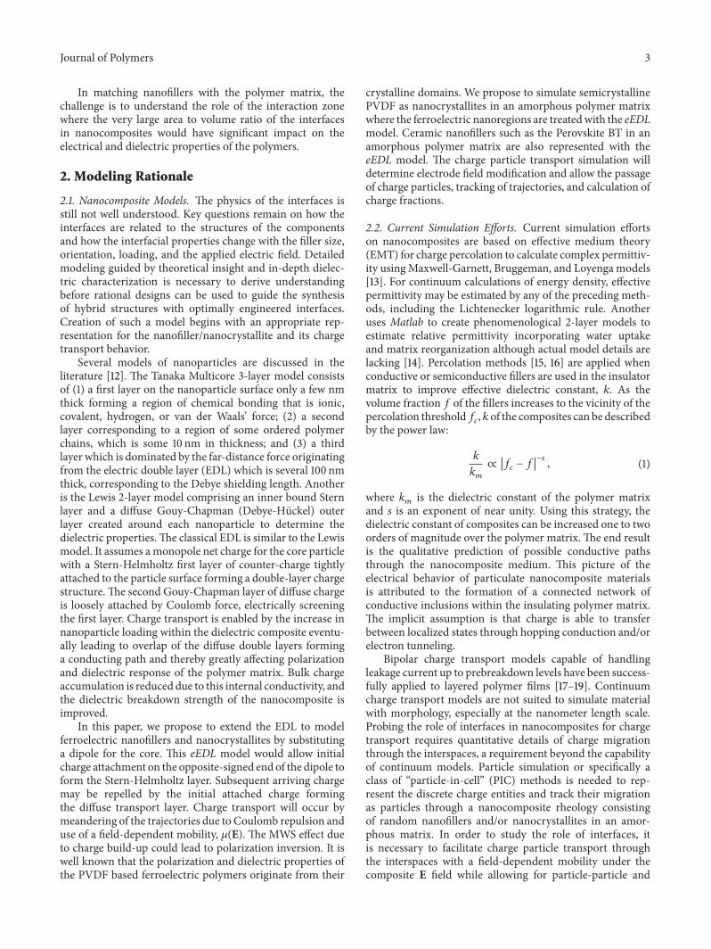
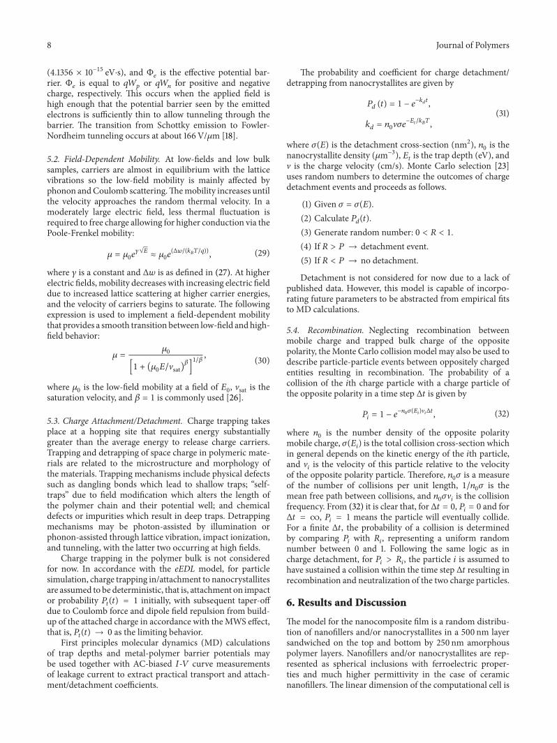
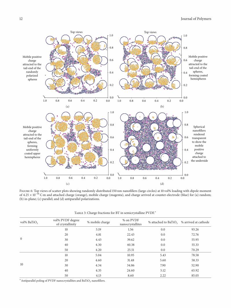
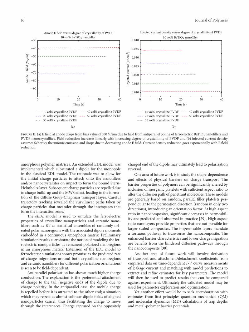