research article visible light communication channel...
TRANSCRIPT
Research ArticleVisible Light Communication Channel Models andSimulation of Coal Workface Energy Coupling
Yanrong Zhai12 and Shen Zhang12
1School of Information and Electrical Engineering China University of Mining amp Technology Xuzhou 221000 China2IOT Perception Mine Research Center China University of Mining amp Technology Xuzhou 221000 China
Correspondence should be addressed to Yanrong Zhai zhaiyanrongcumteducn
Received 24 July 2015 Revised 14 November 2015 Accepted 18 November 2015
Academic Editor Hector E Nistazakis
Copyright copy 2015 Y Zhai and S ZhangThis is an open access article distributed under the Creative CommonsAttribution Licensewhich permits unrestricted use distribution and reproduction in any medium provided the original work is properly cited
Due to their low energy consumption and small size visible light communication systems have been widely used to eliminatecommunication-blind areas in coal workfaces A workface visible light communication channel model and a mathematic model ofenergy coupling from the mining machinersquos workspace to its footpath were established to investigate the characteristics of opticalsignal transmission on the workface This paper studies the effects of coal dust (double-layer particles encapsulated by moisture)on optical signal degradation Simulation results revealed the presence of an optimized transmitter location which maximized thecoupled energy of the two space signals due to the blocking effect of metal columns
1 Introduction
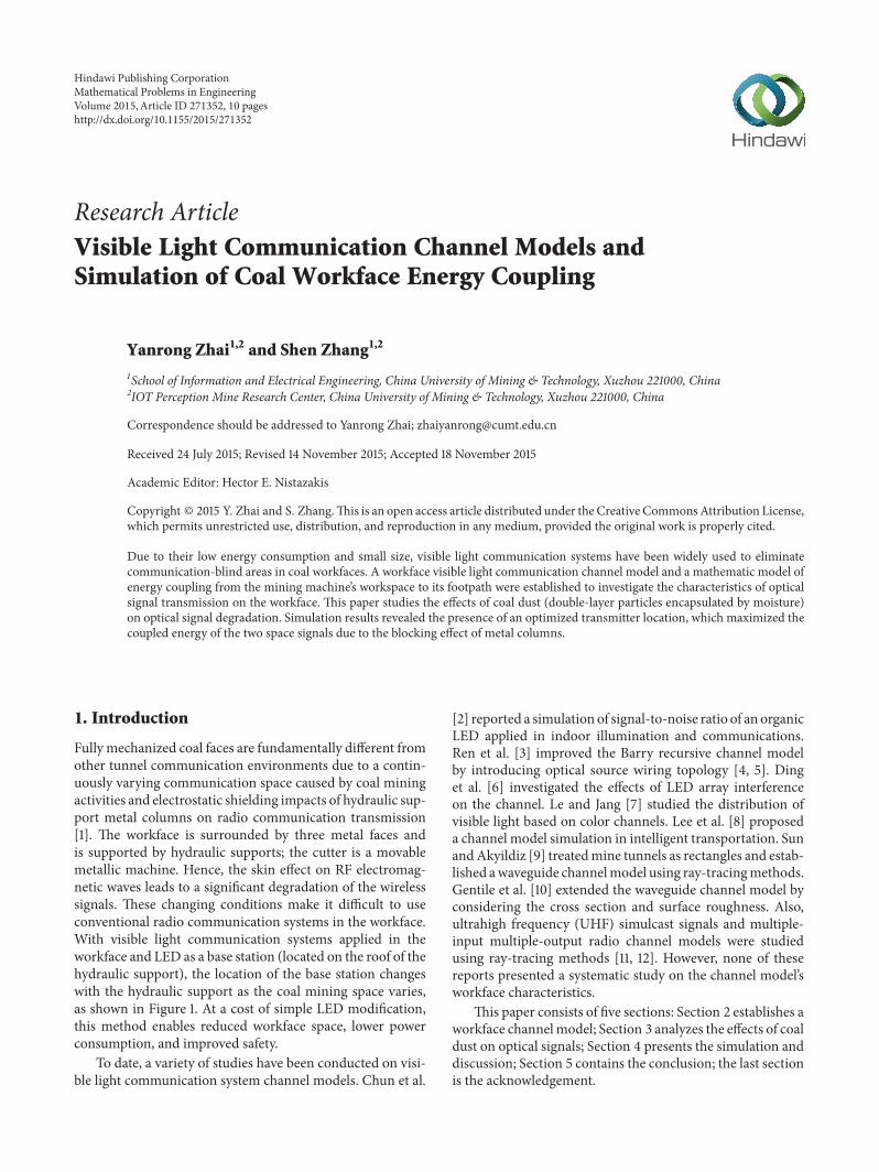
Fully mechanized coal faces are fundamentally different fromother tunnel communication environments due to a contin-uously varying communication space caused by coal miningactivities and electrostatic shielding impacts of hydraulic sup-port metal columns on radio communication transmission[1] The workface is surrounded by three metal faces andis supported by hydraulic supports the cutter is a movablemetallic machine Hence the skin effect on RF electromag-netic waves leads to a significant degradation of the wirelesssignals These changing conditions make it difficult to useconventional radio communication systems in the workfaceWith visible light communication systems applied in theworkface and LED as a base station (located on the roof of thehydraulic support) the location of the base station changeswith the hydraulic support as the coal mining space variesas shown in Figure 1 At a cost of simple LED modificationthis method enables reduced workface space lower powerconsumption and improved safety
To date a variety of studies have been conducted on visi-ble light communication system channel models Chun et al
[2] reported a simulation of signal-to-noise ratio of an organicLED applied in indoor illumination and communicationsRen et al [3] improved the Barry recursive channel modelby introducing optical source wiring topology [4 5] Dinget al [6] investigated the effects of LED array interferenceon the channel Le and Jang [7] studied the distribution ofvisible light based on color channels Lee et al [8] proposeda channel model simulation in intelligent transportation SunandAkyildiz [9] treatedmine tunnels as rectangles and estab-lished awaveguide channelmodel using ray-tracingmethodsGentile et al [10] extended the waveguide channel model byconsidering the cross section and surface roughness Alsoultrahigh frequency (UHF) simulcast signals and multiple-input multiple-output radio channel models were studiedusing ray-tracing methods [11 12] However none of thesereports presented a systematic study on the channel modelrsquosworkface characteristics
This paper consists of five sections Section 2 establishes aworkface channelmodel Section 3 analyzes the effects of coaldust on optical signals Section 4 presents the simulation anddiscussion Section 5 contains the conclusion the last sectionis the acknowledgement
Hindawi Publishing CorporationMathematical Problems in EngineeringVolume 2015 Article ID 271352 10 pageshttpdxdoiorg1011552015271352
2 Mathematical Problems in Engineering
LED
Hydraulic support pillar
SidewalkDownpipe road
Coal particles
Shearer
Miner
(a)
2Coal wall
Shearer
Downpipe road
Metal columns
The secondcommunication
134
5
space
The firstcommunication
space
(b)
Figure 1 (a) Coal workface (b) Coal workface schematic 1 mining machine driver 2 mining machine unloading coal 3 moving frames4 places of multiple operation 5 front slip
columncolumncolumncolumnThe nth The 0th
r
x
r r L
R1R 2 R0R n
120573n
1205731
1205732
1205791120579 2120574 n
12057421205741
middot middot middot
The 2nd The 1st
(a)
rr
r
120572 n 120572 21205721
middot middot middot
x
L Y = K
T1Tn T2
S1S2Sn
l n2
l n1 l 22l 21 l12
l11
l998400
(b)
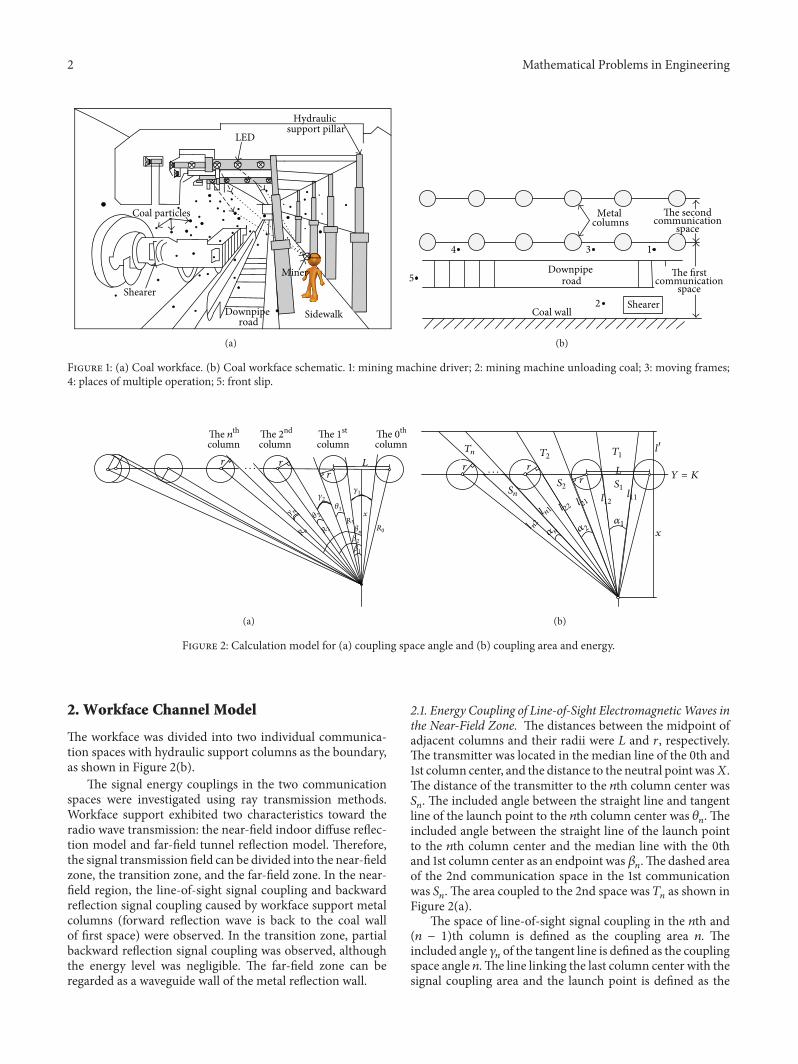
Figure 2 Calculation model for (a) coupling space angle and (b) coupling area and energy
2 Workface Channel Model
The workface was divided into two individual communica-tion spaces with hydraulic support columns as the boundaryas shown in Figure 2(b)
The signal energy couplings in the two communicationspaces were investigated using ray transmission methodsWorkface support exhibited two characteristics toward theradio wave transmission the near-field indoor diffuse reflec-tion model and far-field tunnel reflection model Thereforethe signal transmission field can be divided into the near-fieldzone the transition zone and the far-field zone In the near-field region the line-of-sight signal coupling and backwardreflection signal coupling caused by workface support metalcolumns (forward reflection wave is back to the coal wallof first space) were observed In the transition zone partialbackward reflection signal coupling was observed althoughthe energy level was negligible The far-field zone can beregarded as a waveguide wall of the metal reflection wall
21 Energy Coupling of Line-of-Sight ElectromagneticWaves inthe Near-Field Zone The distances between the midpoint ofadjacent columns and their radii were 119871 and 119903 respectivelyThe transmitter was located in the median line of the 0th and1st column center and the distance to the neutral point was119883The distance of the transmitter to the 119899th column center was119878119899 The included angle between the straight line and tangent
line of the launch point to the 119899th column center was 120579119899 The
included angle between the straight line of the launch pointto the 119899th column center and the median line with the 0thand 1st column center as an endpoint was 120573
119899The dashed area
of the 2nd communication space in the 1st communicationwas 119878119899 The area coupled to the 2nd space was 119879
119899as shown in
Figure 2(a)The space of line-of-sight signal coupling in the 119899th and
(119899 minus 1)th column is defined as the coupling area 119899 Theincluded angle 120574
119899of the tangent line is defined as the coupling
space angle 119899The line linking the last column center with thesignal coupling area and the launch point is defined as the
Mathematical Problems in Engineering 3
coupling boundary The energy coupling surface is at 119910 = 1198701198751198991and 1198751198992are the critical coupling points of their respective
coupling areas The distance between the launch point andthe coupling surface was119883
The coupling space angle can be calculated by
1205741= 2 (120573
1minus 1205791)
120574119899= 120573119899minus 120573119899minus1
minus 120579119899minus 120579119899minus1 119899 ge 2
(1)
where
120573119899= arctan(1198712 + (119899 minus 1) sdot 119871
119909)
120579119899= arcsin( 119903
radic1199092 + (1198712 + (119899 minus 1) sdot 119871)2
)
(2)
The boundary column 119899119899 of the near-field zone andtransition zone satisfies the following conditions
(120573119899119899minus 120573119899119899minus1
) le (120579119899119899+ 120579119899119899minus1
) (3)
Coupling area can be calculated by
119879119899= 119878119899sdot (
(119909 + 1198971015840
)2
1199092minus 1) 119899 ge 1
119878119899=119909
2
10038161003816100381610038161198751198991 minus 11987511989921003816100381610038161003816 119899 ge 1
(4)
where
11987511=minus1198781
119909
11987512=1198781
119909
1198751198991=119871
2+ (119899 minus 2) sdot 119871 +
119903
sin (arctan (1199091198971198991)) 119899 ge 2
1198751198992=119871
2+ (119899 minus 1) sdot 119871 minus
119903
sin (arctan (1199091198971198992)) 119899 ge 2
11989711= 11989712=
119909
cos (1205731minus 1205791)
1205731= arccos( 119909
radic(1198712)2
+ 1199092
)
1205791= arcsin( 119903
radic(1198712)2
+ 1199092
)
1198971198991=
119909
cos (120573119899+ 120579119899) 119899 ge 2
1198971198992=
119909
sin (120576119899+ 120579119899) 119899 ge 2
120576119899= arcsin( 119909
radic(1198712 + (119899 minus 1) sdot 119871)2
+ 1199092
)
(5)
Assuming that function 119878 was at a maximum value thedistance of the signal transmitter to the coupling surface wasobtained In this case the area coupling to another line-of-sight signal space is maximized At 119910 = 119870 energy couplingto the 119899th space line-of-sight signal is
119864 =(119898 + 1)
21205871198892cos119898120593 cos 120592 (6)
where 119898 = ln(12)ln(cos12059312) and 120593
12is half-power angle
of LED Consider
119868119899= int
119911max
119911min
int
1198751198992
1198751198991
119864119896
radic1199092 + 1198962 + 1199112119889119909 119889119911 (7)
where 119911max and 119911min are themaximum andminimumheightsof the coupling surface respectively 119875
1198991and 1198751198992are the criti-
cal points of the 119899th coupling space The total energy currentof coupling is
119868 =
119899119899
sum
119899=1
119868119899 (8)
22 The Line-of-Sight Signals and Impulse Response of aReflection Signal in the Near-Field Zone Impulse responsedelays varied due to the different reflection pathsThe impulseresponses of line-of-sight signals and non-line-of-sight signalare [4]
ℎ(0)
(119905 119878 119877) asymp119899 + 1
2120587cos119899 (120601) 119889Ωrect( 120579
FOV) sdot 120575 (119905
minus119877
119888)
ℎ(119896)
(119905 119878 119877) asymp
119873
sum
119894=1
ℎ(0)
(119905 119904 120576119894) otimes ℎ(119896minus1)
(119905 119904 120576119894) =
119899 + 1
2120587
sdot
119873
sum
119894=1
120588119894cos119899 (120601) cos (120579)
1198772
sdot rect(2120579120587) sdot ℎ(119896minus1)
(119905 minus119877
119888 119903 119899 1 119877)Δ119860
(9)
where 119860 is the received explorer area and 120588119894is the ray energy
current reflectionThe receiving point launching point and reflection point
were assumed to be (1199091 1199101 1199111) (1199092 1199102 1199112) and (119909
119894 119910119894 119911119894)
respectively As shown in Figure 3 four transmission pathswere possible on a smooth reflection surface the roof reflec-tion ray floor reflection ray left column reflection ray andright column reflection ray
4 Mathematical Problems in Engineering
Receivingpoint
Launchingpoint
Reflectionpoint Dis
z1
z2z2Disz1 + z2
z1Disz1 + z2
(a)
Receivingpoint
Launchingpoint
Reflectionpoint
Dis
z1
z2
z1Disz2 minus z1 Dis1
z1 +Dis1(z2 minus z1)
Dis
(b)
Figure 3 (a) Roof and floor reflection point coordinates (b) metal column reflection point coordinates
The roof or baseboard reflection point coordinates are
1199091minus1199111Dis
1199111+ 1199112
cos 119886
1199111Dis
1199111+ 1199112
sin 119886(10)
where 119911 is height of roof or baseboard
Dis = radic(1199091minus 1199092)2
+ (1199101minus 1199102)2
sin 119886 =10038161003816100381610038161199101 minus 1199102
1003816100381610038161003816
Dis
(11)
The roof or baseboard reflection point coordinates in the119899th coupling space metal column are
(11987511989911198992
119896 1199111Dis 10038161003816100381610038161199111 minus 1199112
1003816100381610038161003816
Dis) (12)
3 Attenuation Effects of Coal DustParticles on Optical Signal
Coal dust particles have strong absorption effects on electro-magnetic and lightwavesTheworking coal cutter generated aconsiderable amount of floating coal dust particles resultingin light signal attenuation due to scattering and absorptionby these suspending particles The relation between inci-dent light intensity and transmission light intensity can beexpressed as follows [13]
119868 = 1198680119890(minus(32)sdot(119862119871119870
119890119889))
(13)
where 119862 is the number of suspending particles in the unitvolume (cm3)119871 is light path (cm) and119870
119890is light attenuation
coefficient 119870119890= 119876sca + 119876abs
Currently themostwidely usedmethod forworkface dustprevention is coal seam water infusion This method causesdust fall and wetting water vapor is produced and absorbedby coal particle surfaces A previous study [14] reported thatthe contact angle of coal particles with an average grainsize of 375ndash1971120583m ranged from 8739∘ to 9000∘ indicatingthat the particles were hydrophobic as shown in Figure 5Therefore workface coal dust can be regarded as a conden-sation nucleus covered by a thin water vapor layer Coal
dust particles settle when they coagulate with sufficient watermolecules
Mie scattering is a rigorous solution to scattering prob-lems of uniform spherical particles of any sizeThe scatteringabsorption effect of dust particles of diameters comparableto the radiation wavelength can be investigated using Miescattering The Mie factors of double-layer particles (119886
119899and
119887119899) are [15]
119886119899=
(1198631198991198982+ 119899119910)120595
119899(119910) minus 120595
(119899minus1)(119910)
(1198631198991198982+ 119899119910) 120585
119899(119910) minus 120585
119899minus1(119910)
119887119899=
(1198982119866119899+ 119899119910)120595
119899(119910) minus 120595
119899minus1(119910)
(1198982119866119899+ 119899119910) 120585
119899(119910) minus 120585
119899minus1(119910)
(14)
where
119863119899=119863119899(1198982119910) minus 119860
1198991205941015840
119899(1198982119910) 120595119899(1198982119910)
1 minus 119860119899120594119899(1198982119910) 120595119899(1198982119910)
119866119899=119863119899(1198982119910) minus 119861
1198991205941015840
119899(1198982119910) 120595119899(1198982119910)
1 minus 119861119899120594119899(1198982119910) 120595119899(1198982119910)
119860119899= 120595119899(1198982119909)
119898119863119899(1198981119909) minus 119863
119899(1198982119909)
119898119863119899(1198981119909) 120594119899(1198982119909) minus 1205941015840
119899(1198982119909)
119861119899= 120595119899(1198982119909)
119863119899(1198981119909) 119898 minus 119863
119899(1198982119909)
119863119899(1198981119909) 120594119899(1198982119909) 119898 minus 1205941015840
119899(1198982119909)
119863119899(119911) =
1205951015840
119899(119911)
120595119899(119911)
119898 =1198982
1198981
120594119899(119911) = minus119911radic
120587
2119911119884119899+05
(119911)
120595119899(119911) = 119911radic
120587
2119911119869119899+05
(119911)
120585119899= 119911(radic
120587
2119911119869119899+05
(119911) + 119894radic120587
2119911119884119899+05
(119911))
(15)
119869 and 119884 are Bessel functions of the first kind order 119899 and thesecond kind order 119899 respectively
Mathematical Problems in Engineering 5
The corresponding extinction efficiency factor 119876est for-ward scattering factor 119876sca and absorption factor 119876abs [16]are expressed as
119876sca =2
1199092
119899119888
sum
119899=1
(2119899 + 1) (10038161003816100381610038161198861198991003816100381610038161003816
2
+10038161003816100381610038161198871198991003816100381610038161003816
2
)
119876est =2
1199092
119899119888
sum
119899=1
(2119899 + 1)R 119886119899+ 119887119899
119876abs asymp 119876est minus 119876sca
(16)
The backward-scattering coefficient 119876bac and the averagecosine of the scattering angle with respect to power are asfollows [17]
119876bac =1
1199092
1003816100381610038161003816100381610038161003816100381610038161003816
119899119888
sum
119899=1
(2119899 + 1) (minus1)119899
(119886119899minus 119887119899)
1003816100381610038161003816100381610038161003816100381610038161003816
2
119876sca ⟨cos 120579⟩ =4
1199092
infin
sum
119899=1
119899 (119899 + 2)
119899 + 1Re (119886119899119886lowast
119899+1+ 119887119899119887lowast
119899+1)
+
infin
sum
119899+1
2119899 + 1
119899 (119899 + 1)Re (119886119899119887lowast
119899)
119899119888= 119909 + 4119909
13
+ 1
(17)
where Re stands for the real part
4 Simulation and Analysis
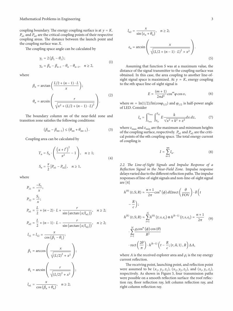
41 The Effect of Coal Dust Water Vapor on the Light SignalSimulations based on grain size of 2 120583m 4 120583m 7 120583m and10 120583m using Mie coefficients of different water vapor layerthicknesses were conducted and shown in Figure 4
According to Figure 4 the scattering absorption coeffi-cient fluctuated with water vapor thickness and the fluctua-tion degree increased with the thickness of the water vaporlayer The coefficients tend to be stable and eventually con-verged to a straight line as thickness decreased Additionallythe effect of water vapor layer thickness on the extinctionscattering coefficient increased as the nuclei radius decreasedindicating that the water vapor covering coal dust has aneffect on coal dustrsquos light scattering absorption Thereforecoal dust characteristics andwater vapor layer thicknessmustbe investigated to understand the effects of coal dust particleson light signals
Dong et al [14] used a German automatic measuringinstrument (operatingmanual DACT21) to performQLM-90airstream grinding on coal samples obtained from five coalpreparation plants (QTH TF DD XS and QX)The elemen-tal composition and ash content of coal in different miningareas have been described elsewhere [14] Based on differentturbo classifying convolution coal samples from each plantwere divided into 4 groups with different average grain sizesThe watercoal wetting balance contact angles of the 20
Table 1 Characteristics in simulation for signal pulse response andenergy coupling
Total grain swarm average grain size(weighted average)
76018 120583m
Water vapor thickness 26596 120583m
Extinction coefficient 21162
Scattering coefficient 14115
Absorption coefficient 07011
coal sample groups were measured the results are shown inFigure 5
According to Figure 5 the contact angles of four coalsamples groups with grain sizes of 3ndash20120583m from QTHDD XS and QX remained constant at 899∘ The coalsample contact angle from TF was slightly smaller than othersamples with the same grain size the fluctuation range wasabout 15∘
According to the lengthmeasuringmethod of the wettingcontact angle the water vapor layer thickness absorbedaround coal dust particles was estimated by sin 120579 = 2ℎ119903(ℎ2 +1199032
) or sin(1205792) = ℎ119903 The corresponding scattering absorp-tion coefficients were obtained and shown in Figure 6
According to Figure 6 the Mie coefficients of DD andTF samples with a 76 120583m grain size (except for the backscattering coefficient) were almost the same demonstratingthat the differences in the contact angle did not affect theMiecoefficientsTherefore the scattering absorption coefficient ofwet coal dust particles (3ndash20120583m)was determined by the grainradius
Since workface dust consists of particles with differentgrain sizes the average granularity calculated by statisticalmathematics was used for simulations Zuo [18] investigatedthe statistics of particles from Bulianta Mine of ShendongCoal Group Corporation Limited 22306 comprehensivemining workface coal cutter driving position coal cuttercoal falling position moving frame position and multipleprocesses position by using aWinner 99Microscopic ParticleImage Analyzer as shown in Figure 1(b) Set the coal dustgrain size from these five positions as grain swarm theparticle characteristics in the simulations for the signal pulseresponse and energy coupling were obtained and shown inTable 1
42 Energy Coupling of Line-of-Sight Signals According tothe parameters of the ZY92002550D hydraulic support thecentral distance was 175m the supporting height was 3mthe supporting width was 176m the cylinder diameter was400mm and the pillar diameter was 380mm A MLS3-170coal cutter andDGWD-180 conveyorwere usedThematchedsize was 1972mm the top beam length was 3700mm and theline-of-sight signals and first-order reflection NLOS signalchannel were simulated The emitting and receiving pointcoordinates were (10 6 25) and (10 1 08) respectively TheLED half power angle was 60∘
6 Mathematical Problems in Engineering
2120583m4120583m
7120583m10120583m
02 04 06 08 10(r minus h)r
18
2
22
24
26
28
(a) 119876est
2120583m4120583m
7120583m10120583m
02 04 06 08 10(r minus h)r
1
12
14
16
18
2
(b) 119876sca
2120583m4120583m
7120583m10120583m
02 04 06 08 10(r minus h)r
04
05
06
07
08
09
1
(c) 119876abs
2120583m4120583m
7120583m10120583m
0
05
1
15
02 04 06 08 10(r minus h)r
(d) 119876bac
2120583m4120583m
7120583m10120583m
075
08
085
09
095
1
02 04 06 08 10(r minus h)r
(e) 119876sca⟨cos 120579⟩
2120583m4120583m
7120583m10120583m
0
02
04
06
08
1
02 04 06 08 10(r minus h)r
(f) 119876bac119876sca
Figure 4 Scattering absorption coefficients of particles with different grain sizes versus water vapor layer thickness
Mathematical Problems in Engineering 7
87
88
89
90
91
Ang
le
QTHTFDD
XSQX
5 10 15 200Radius (120583m)
Figure 5 Contact angle of different coal samples
TFDD
0
05
1
15
2
25
5 10 15 200Radius (120583m)
QestQscaQabs
QbacQsca⟨cos 120579⟩
Figure 6 Relation between the contact angle and the scatteringabsorption coefficient
Figure 7 shows an illustration of the light energy streamreflection from air to iron The reflecting ratio remainedconstant at 056 if the reflecting angle was between 0 and60∘ Figure 8 shows the pulse response of line-of-sight signalsand first-order NLOS reflection signals Time delays causedby the direct path signal and nearest pillar reflection signalwere comparable However signal strength decreased as thepillar distance increasedThe intensity of forward path signals
Parallel componentVertical componentTotal
20 40 60 80 1000Angle
0
02
04
06
08
1
Ener
gy re
flect
ance
Figure 7 Energy reflection coefficient of 650 nm light from air toiron
(Figure 8(a)) was higher than that of reflection path signalsAs shown in Figure 8(b) only one peak of reflection pathsignal intensity was observed between the first pillar and thesecond pillar which can be attributed to the signal overlap-ping Additionally the signal intensity via the reflection pathof the roof (Figure 8(c)) was significantly higher than that viathe reflection path of the floor (Figure 8(d)) as the reflectionmedium on the floor was coal while the reflection mediumon the roof was steel
According to Figures 9(a) and 9(b) trends of the couplingangle and each coupling area were highly similar Howeverthe trends of the coupling angle and coupling area in thefirst space were different from those in other spaces Atshort distances coupling angles coupling areas and couplingenergy in other spaces were negligible This can be attributedto the fact that the coupling angle and coupling area wereinversely proportional to the distance as the light sourcewas along the perpendicular bisector of the first space Atshort distances the light source was roughly parallel to thecoupling boundary and the coupling angle was negligibleAs the distance increased energy coupling was observed indifferent coupling spaces Figure 9(c) shows that when theemitting point was 13m away from the coupling plan thetotal coupling energy stream was maximized In Figure 9(d)since the electromagnetic wave attenuated faster in the visiblelightwaveband the light energy attenuation scales in differentareas were different Nevertheless as distance increased thisscale tended to be stable at 01 and a coupling energy peakpoint existed when the emitting point was coupled to everyfield Although the coupling area of first field area increasedas the distance decreased when the emitter was close to thecoupling plan the existing line-of-sight signal coupling area
8 Mathematical Problems in Engineering
Am
plitu
de
times10minus7
times10minus1005 1 150
Time (s)
0
05
1
15
(a) Line-of-sight
0 05 1 150
2
4
6
8
Time (s)
Am
plitu
de
times10minus10
times10minus10
(b) The left and right columns reflection rays
0 05 1 150
2
4
6
8
Time (s)
Am
plitu
de
times10minus10
times10minus9
(c) The roof reflection ray
times10minus11
times10minus1005 1 150
Time (s)
0
05
1
15
2
25
Am
plitu
de
(d) The floor reflection ray
Figure 8 Line-of-sight and first-order reflecting signal pulse response
decreased due to the pillar sheltering effect thus a peak valuestill existed in the first field area Relative to the distance fromthe emitter and coupling plan the pillar radius was so smallthat it can be taken as a point and no energy coupling peakvalue was observed in the first coupling field area
5 Conclusions
Due to the presence of water vapor coal dust particles shouldbe regarded as water vapor-covered double-layer particles forthe study of attenuation effects caused by coal dust particleson wireless light signals Also the slight change of the coaldust wetting contact angle did not have a significant effect
on the grain scattering absorption coefficient Therefore thewater vapor thickness of coal dust particles in the workfacewas determined by the grain size For signal couplings in dif-ferent communication spaces a maximum energy couplingvalue was presented in every field due to the sheltering effectof the metal pillar This benefits the determination of emitterposition and receiver signal energy and power analysis
Conflict of Interests
The authors declare that there is no conflict of interestsregarding the publication of this paper
Mathematical Problems in Engineering 9
0 5 10 15Distance (m)
Area 1Area 2Area 3
Area 4Area 5
0
05
1
15
2
25
3
Ang
le (d
eg)
(a) Coupling angle
0
5
10
15
5 10 150Distance (m)
Area 1Area 2Area 3
Area 4Area 5
Are
a (m
2 )
(b) Coupling area
5 10 150Distance (m)
0
05
1
15
2
Ener
gy (J
)
Area 1Area 2Area 3
Area 4Area 5
(c) Coupling energy
0 5 10 15Distance (m)
0
05
1
15
2
25
3
Tota
l ene
rgy
(J)
(d) Coupling total energy
Figure 9 Simulation of coupling field area coupling space and coupling energy
Acknowledgments
The authors gratefully acknowledge the support of TheNational Science amp Technology Pillar Program of China(2013BAK06B05) and Postgraduate Training InnovationProject of Jiangsu Province (KYLX 1387)
References
[1] X L Feng and J S Qian ldquoArchitecture of wireless multimediamesh network nodes for longwall coal mine automationrdquo inProceedings of the 3rd International Conference on Informationand Computing (ICIC rsquo10) vol 2 pp 42ndash45 IEEEWuxi ChinaJune 2010
10 Mathematical Problems in Engineering
[2] H Chun C-J Chiang and D C OrsquoBrien ldquoVisible light com-munication using OLEDs illumination and channel modelingrdquoin Proceedings of the International Workshop on Optical WirelessCommunications (IWOW rsquo12) pp 1ndash3 IEEE Pisa Italy October2012
[3] G H Ren S Y He and Y L Yang ldquoAn improved recursivechannelmodel for indoor visible light communication systemsrdquoInformation Technology Journal vol 12 no 6 pp 1245ndash12502013
[4] J R Barry J M KahnW J Krause E A Lee andD GMesser-chmitt ldquoSimulation of multipath impulse response for indoorwireless optical channelsrdquo IEEE Journal on Selected Areas inCommunications vol 11 no 3 pp 367ndash379 1993
[5] K Lee H Park and J R Barry ldquoIndoor channel characteristicsfor visible light communicationsrdquo IEEE Communications Let-ters vol 15 no 2 pp 217ndash219 2011
[6] J P Ding K Wang and Z G Xu ldquoImpact of LED arraysimplification on indoor visible light communication channelmodelingrdquo in Proceedings of the 9th International Symposium onCommunication Systems Networks amp Digital Signal Processing(CSNDS rsquo14) pp 1159ndash1164 IEEE Manchester UK July 2014
[7] N-T Le and Y M Jang ldquoSmart color channel allocation forvisible light communication cell IDrdquo Optical Switching andNetworking vol 15 pp 75ndash86 2015
[8] S J Lee J K Kwon S Y Jung and Y H Kwon ldquoSimulationmodeling of visible light communication channel for automo-tive applicationsrdquo in Proceedings of the 2012 15th InternationalIEEE Conference on Intelligent Transportation Systems pp 463ndash468 Anchorage Alaska USA September 2012
[9] Z Sun and I F Akyildiz ldquoChannel modeling and analysis forwireless networks in underground mines and road tunnelsrdquoIEEE Transactions on Communications vol 58 no 6 pp 1758ndash1768 2010
[10] C Gentile F Valoit and N Moayeri ldquoA raytracing model forwireless propagation in tunnels with varying cross sectionrdquo inProceedings of the IEEE Global Communications Conference(GLOBECOM rsquo12) pp 5027ndash5032 IEEE Anaheim Calif USADecember 2012
[11] Y P Zhang Y Hwang and J H Sheng ldquoPropagation charac-teristics of UHF simulcast signals in tunnel environmentsrdquo inProceedings of the International Conference on CommunicationTechnology (ICCT rsquo96) vol 1 pp 457ndash460 IEEE Beijing ChinaMay 1996
[12] S-H Yao andX-LWu ldquoModeling forMIMOwireless channelsin mine tunnelsrdquo in Proceedings of the International Conferenceon Electric Information and Control Engineering (ICEICE rsquo11)pp 520ndash523 IEEE Wuhan China April 2011
[13] L Wang Research on Retrieval Algorithm of Particle Size Distri-bution Based on Spectral Extinction Method Harbin Institute ofTechnology 2013
[14] P Dong Z J Shan and Z Li ldquoStudy on the surface wet charac-teristic of ultrafine coal powderrdquo Journal of China Coal Societyvol 29 no 3 pp 346ndash349 2004
[15] N G Volkov and V Y Kovach ldquoScattering of light by inho-mogeneous spherically symmetrical aerosol particlesrdquo IzvestiyaAtmospheric and Oceanic Physics vol 26 no 5 pp 381ndash3851990
[16] H C V Hulst Light Scattering by Small Particle Wiley NewYork NY USA 1957
[17] W E Meador and W R Weaver ldquoTwo-stream approximationsto radiative transfer in planetary atmospheres a unifieddescrip-tion of existingmethods and a new improvementrdquo Journal of theAtmospheric Sciences vol 37 no 3 pp 630ndash643 1980
[18] Q M Zuo Diffusion Law and Dust Control Techniques ofLarge Mining Height Fully-Mechanized Face China Universityof Mining and Technology Xuzhou China 2014
Submit your manuscripts athttpwwwhindawicom
Hindawi Publishing Corporationhttpwwwhindawicom Volume 2014
MathematicsJournal of
Hindawi Publishing Corporationhttpwwwhindawicom Volume 2014
Mathematical Problems in Engineering
Hindawi Publishing Corporationhttpwwwhindawicom
Differential EquationsInternational Journal of
Volume 2014
Applied MathematicsJournal of
Hindawi Publishing Corporationhttpwwwhindawicom Volume 2014
Probability and StatisticsHindawi Publishing Corporationhttpwwwhindawicom Volume 2014
Journal of
Hindawi Publishing Corporationhttpwwwhindawicom Volume 2014
Mathematical PhysicsAdvances in
Complex AnalysisJournal of
Hindawi Publishing Corporationhttpwwwhindawicom Volume 2014
OptimizationJournal of
Hindawi Publishing Corporationhttpwwwhindawicom Volume 2014
CombinatoricsHindawi Publishing Corporationhttpwwwhindawicom Volume 2014
International Journal of
Hindawi Publishing Corporationhttpwwwhindawicom Volume 2014
Operations ResearchAdvances in
Journal of
Hindawi Publishing Corporationhttpwwwhindawicom Volume 2014
Function Spaces
Abstract and Applied AnalysisHindawi Publishing Corporationhttpwwwhindawicom Volume 2014
International Journal of Mathematics and Mathematical Sciences
Hindawi Publishing Corporationhttpwwwhindawicom Volume 2014
The Scientific World JournalHindawi Publishing Corporation httpwwwhindawicom Volume 2014
Hindawi Publishing Corporationhttpwwwhindawicom Volume 2014
Algebra
Discrete Dynamics in Nature and Society
Hindawi Publishing Corporationhttpwwwhindawicom Volume 2014
Hindawi Publishing Corporationhttpwwwhindawicom Volume 2014
Decision SciencesAdvances in
Discrete MathematicsJournal of
Hindawi Publishing Corporationhttpwwwhindawicom
Volume 2014 Hindawi Publishing Corporationhttpwwwhindawicom Volume 2014
Stochastic AnalysisInternational Journal of
2 Mathematical Problems in Engineering
LED
Hydraulic support pillar
SidewalkDownpipe road
Coal particles
Shearer
Miner
(a)
2Coal wall
Shearer
Downpipe road
Metal columns
The secondcommunication
134
5
space
The firstcommunication
space
(b)
Figure 1 (a) Coal workface (b) Coal workface schematic 1 mining machine driver 2 mining machine unloading coal 3 moving frames4 places of multiple operation 5 front slip
columncolumncolumncolumnThe nth The 0th
r
x
r r L
R1R 2 R0R n
120573n
1205731
1205732
1205791120579 2120574 n
12057421205741
middot middot middot
The 2nd The 1st
(a)
rr
r
120572 n 120572 21205721
middot middot middot
x
L Y = K
T1Tn T2
S1S2Sn
l n2
l n1 l 22l 21 l12
l11
l998400
(b)
Figure 2 Calculation model for (a) coupling space angle and (b) coupling area and energy
2 Workface Channel Model
The workface was divided into two individual communica-tion spaces with hydraulic support columns as the boundaryas shown in Figure 2(b)
The signal energy couplings in the two communicationspaces were investigated using ray transmission methodsWorkface support exhibited two characteristics toward theradio wave transmission the near-field indoor diffuse reflec-tion model and far-field tunnel reflection model Thereforethe signal transmission field can be divided into the near-fieldzone the transition zone and the far-field zone In the near-field region the line-of-sight signal coupling and backwardreflection signal coupling caused by workface support metalcolumns (forward reflection wave is back to the coal wallof first space) were observed In the transition zone partialbackward reflection signal coupling was observed althoughthe energy level was negligible The far-field zone can beregarded as a waveguide wall of the metal reflection wall
21 Energy Coupling of Line-of-Sight ElectromagneticWaves inthe Near-Field Zone The distances between the midpoint ofadjacent columns and their radii were 119871 and 119903 respectivelyThe transmitter was located in the median line of the 0th and1st column center and the distance to the neutral point was119883The distance of the transmitter to the 119899th column center was119878119899 The included angle between the straight line and tangent
line of the launch point to the 119899th column center was 120579119899 The
included angle between the straight line of the launch pointto the 119899th column center and the median line with the 0thand 1st column center as an endpoint was 120573
119899The dashed area
of the 2nd communication space in the 1st communicationwas 119878119899 The area coupled to the 2nd space was 119879
119899as shown in
Figure 2(a)The space of line-of-sight signal coupling in the 119899th and
(119899 minus 1)th column is defined as the coupling area 119899 Theincluded angle 120574
119899of the tangent line is defined as the coupling
space angle 119899The line linking the last column center with thesignal coupling area and the launch point is defined as the
Mathematical Problems in Engineering 3
coupling boundary The energy coupling surface is at 119910 = 1198701198751198991and 1198751198992are the critical coupling points of their respective
coupling areas The distance between the launch point andthe coupling surface was119883
The coupling space angle can be calculated by
1205741= 2 (120573
1minus 1205791)
120574119899= 120573119899minus 120573119899minus1
minus 120579119899minus 120579119899minus1 119899 ge 2
(1)
where
120573119899= arctan(1198712 + (119899 minus 1) sdot 119871
119909)
120579119899= arcsin( 119903
radic1199092 + (1198712 + (119899 minus 1) sdot 119871)2
)
(2)
The boundary column 119899119899 of the near-field zone andtransition zone satisfies the following conditions
(120573119899119899minus 120573119899119899minus1
) le (120579119899119899+ 120579119899119899minus1
) (3)
Coupling area can be calculated by
119879119899= 119878119899sdot (
(119909 + 1198971015840
)2
1199092minus 1) 119899 ge 1
119878119899=119909
2
10038161003816100381610038161198751198991 minus 11987511989921003816100381610038161003816 119899 ge 1
(4)
where
11987511=minus1198781
119909
11987512=1198781
119909
1198751198991=119871
2+ (119899 minus 2) sdot 119871 +
119903
sin (arctan (1199091198971198991)) 119899 ge 2
1198751198992=119871
2+ (119899 minus 1) sdot 119871 minus
119903
sin (arctan (1199091198971198992)) 119899 ge 2
11989711= 11989712=
119909
cos (1205731minus 1205791)
1205731= arccos( 119909
radic(1198712)2
+ 1199092
)
1205791= arcsin( 119903
radic(1198712)2
+ 1199092
)
1198971198991=
119909
cos (120573119899+ 120579119899) 119899 ge 2
1198971198992=
119909
sin (120576119899+ 120579119899) 119899 ge 2
120576119899= arcsin( 119909
radic(1198712 + (119899 minus 1) sdot 119871)2
+ 1199092
)
(5)
Assuming that function 119878 was at a maximum value thedistance of the signal transmitter to the coupling surface wasobtained In this case the area coupling to another line-of-sight signal space is maximized At 119910 = 119870 energy couplingto the 119899th space line-of-sight signal is
119864 =(119898 + 1)
21205871198892cos119898120593 cos 120592 (6)
where 119898 = ln(12)ln(cos12059312) and 120593
12is half-power angle
of LED Consider
119868119899= int
119911max
119911min
int
1198751198992
1198751198991
119864119896
radic1199092 + 1198962 + 1199112119889119909 119889119911 (7)
where 119911max and 119911min are themaximum andminimumheightsof the coupling surface respectively 119875
1198991and 1198751198992are the criti-
cal points of the 119899th coupling space The total energy currentof coupling is
119868 =
119899119899
sum
119899=1
119868119899 (8)
22 The Line-of-Sight Signals and Impulse Response of aReflection Signal in the Near-Field Zone Impulse responsedelays varied due to the different reflection pathsThe impulseresponses of line-of-sight signals and non-line-of-sight signalare [4]
ℎ(0)
(119905 119878 119877) asymp119899 + 1
2120587cos119899 (120601) 119889Ωrect( 120579
FOV) sdot 120575 (119905
minus119877
119888)
ℎ(119896)
(119905 119878 119877) asymp
119873
sum
119894=1
ℎ(0)
(119905 119904 120576119894) otimes ℎ(119896minus1)
(119905 119904 120576119894) =
119899 + 1
2120587
sdot
119873
sum
119894=1
120588119894cos119899 (120601) cos (120579)
1198772
sdot rect(2120579120587) sdot ℎ(119896minus1)
(119905 minus119877
119888 119903 119899 1 119877)Δ119860
(9)
where 119860 is the received explorer area and 120588119894is the ray energy
current reflectionThe receiving point launching point and reflection point
were assumed to be (1199091 1199101 1199111) (1199092 1199102 1199112) and (119909
119894 119910119894 119911119894)
respectively As shown in Figure 3 four transmission pathswere possible on a smooth reflection surface the roof reflec-tion ray floor reflection ray left column reflection ray andright column reflection ray
4 Mathematical Problems in Engineering
Receivingpoint
Launchingpoint
Reflectionpoint Dis
z1
z2z2Disz1 + z2
z1Disz1 + z2
(a)
Receivingpoint
Launchingpoint
Reflectionpoint
Dis
z1
z2
z1Disz2 minus z1 Dis1
z1 +Dis1(z2 minus z1)
Dis
(b)
Figure 3 (a) Roof and floor reflection point coordinates (b) metal column reflection point coordinates
The roof or baseboard reflection point coordinates are
1199091minus1199111Dis
1199111+ 1199112
cos 119886
1199111Dis
1199111+ 1199112
sin 119886(10)
where 119911 is height of roof or baseboard
Dis = radic(1199091minus 1199092)2
+ (1199101minus 1199102)2
sin 119886 =10038161003816100381610038161199101 minus 1199102
1003816100381610038161003816
Dis
(11)
The roof or baseboard reflection point coordinates in the119899th coupling space metal column are
(11987511989911198992
119896 1199111Dis 10038161003816100381610038161199111 minus 1199112
1003816100381610038161003816
Dis) (12)
3 Attenuation Effects of Coal DustParticles on Optical Signal
Coal dust particles have strong absorption effects on electro-magnetic and lightwavesTheworking coal cutter generated aconsiderable amount of floating coal dust particles resultingin light signal attenuation due to scattering and absorptionby these suspending particles The relation between inci-dent light intensity and transmission light intensity can beexpressed as follows [13]
119868 = 1198680119890(minus(32)sdot(119862119871119870
119890119889))
(13)
where 119862 is the number of suspending particles in the unitvolume (cm3)119871 is light path (cm) and119870
119890is light attenuation
coefficient 119870119890= 119876sca + 119876abs
Currently themostwidely usedmethod forworkface dustprevention is coal seam water infusion This method causesdust fall and wetting water vapor is produced and absorbedby coal particle surfaces A previous study [14] reported thatthe contact angle of coal particles with an average grainsize of 375ndash1971120583m ranged from 8739∘ to 9000∘ indicatingthat the particles were hydrophobic as shown in Figure 5Therefore workface coal dust can be regarded as a conden-sation nucleus covered by a thin water vapor layer Coal
dust particles settle when they coagulate with sufficient watermolecules
Mie scattering is a rigorous solution to scattering prob-lems of uniform spherical particles of any sizeThe scatteringabsorption effect of dust particles of diameters comparableto the radiation wavelength can be investigated using Miescattering The Mie factors of double-layer particles (119886
119899and
119887119899) are [15]
119886119899=
(1198631198991198982+ 119899119910)120595
119899(119910) minus 120595
(119899minus1)(119910)
(1198631198991198982+ 119899119910) 120585
119899(119910) minus 120585
119899minus1(119910)
119887119899=
(1198982119866119899+ 119899119910)120595
119899(119910) minus 120595
119899minus1(119910)
(1198982119866119899+ 119899119910) 120585
119899(119910) minus 120585
119899minus1(119910)
(14)
where
119863119899=119863119899(1198982119910) minus 119860
1198991205941015840
119899(1198982119910) 120595119899(1198982119910)
1 minus 119860119899120594119899(1198982119910) 120595119899(1198982119910)
119866119899=119863119899(1198982119910) minus 119861
1198991205941015840
119899(1198982119910) 120595119899(1198982119910)
1 minus 119861119899120594119899(1198982119910) 120595119899(1198982119910)
119860119899= 120595119899(1198982119909)
119898119863119899(1198981119909) minus 119863
119899(1198982119909)
119898119863119899(1198981119909) 120594119899(1198982119909) minus 1205941015840
119899(1198982119909)
119861119899= 120595119899(1198982119909)
119863119899(1198981119909) 119898 minus 119863
119899(1198982119909)
119863119899(1198981119909) 120594119899(1198982119909) 119898 minus 1205941015840
119899(1198982119909)
119863119899(119911) =
1205951015840
119899(119911)
120595119899(119911)
119898 =1198982
1198981
120594119899(119911) = minus119911radic
120587
2119911119884119899+05
(119911)
120595119899(119911) = 119911radic
120587
2119911119869119899+05
(119911)
120585119899= 119911(radic
120587
2119911119869119899+05
(119911) + 119894radic120587
2119911119884119899+05
(119911))
(15)
119869 and 119884 are Bessel functions of the first kind order 119899 and thesecond kind order 119899 respectively
Mathematical Problems in Engineering 5
The corresponding extinction efficiency factor 119876est for-ward scattering factor 119876sca and absorption factor 119876abs [16]are expressed as
119876sca =2
1199092
119899119888
sum
119899=1
(2119899 + 1) (10038161003816100381610038161198861198991003816100381610038161003816
2
+10038161003816100381610038161198871198991003816100381610038161003816
2
)
119876est =2
1199092
119899119888
sum
119899=1
(2119899 + 1)R 119886119899+ 119887119899
119876abs asymp 119876est minus 119876sca
(16)
The backward-scattering coefficient 119876bac and the averagecosine of the scattering angle with respect to power are asfollows [17]
119876bac =1
1199092
1003816100381610038161003816100381610038161003816100381610038161003816
119899119888
sum
119899=1
(2119899 + 1) (minus1)119899
(119886119899minus 119887119899)
1003816100381610038161003816100381610038161003816100381610038161003816
2
119876sca ⟨cos 120579⟩ =4
1199092
infin
sum
119899=1
119899 (119899 + 2)
119899 + 1Re (119886119899119886lowast
119899+1+ 119887119899119887lowast
119899+1)
+
infin
sum
119899+1
2119899 + 1
119899 (119899 + 1)Re (119886119899119887lowast
119899)
119899119888= 119909 + 4119909
13
+ 1
(17)
where Re stands for the real part
4 Simulation and Analysis
41 The Effect of Coal Dust Water Vapor on the Light SignalSimulations based on grain size of 2 120583m 4 120583m 7 120583m and10 120583m using Mie coefficients of different water vapor layerthicknesses were conducted and shown in Figure 4
According to Figure 4 the scattering absorption coeffi-cient fluctuated with water vapor thickness and the fluctua-tion degree increased with the thickness of the water vaporlayer The coefficients tend to be stable and eventually con-verged to a straight line as thickness decreased Additionallythe effect of water vapor layer thickness on the extinctionscattering coefficient increased as the nuclei radius decreasedindicating that the water vapor covering coal dust has aneffect on coal dustrsquos light scattering absorption Thereforecoal dust characteristics andwater vapor layer thicknessmustbe investigated to understand the effects of coal dust particleson light signals
Dong et al [14] used a German automatic measuringinstrument (operatingmanual DACT21) to performQLM-90airstream grinding on coal samples obtained from five coalpreparation plants (QTH TF DD XS and QX)The elemen-tal composition and ash content of coal in different miningareas have been described elsewhere [14] Based on differentturbo classifying convolution coal samples from each plantwere divided into 4 groups with different average grain sizesThe watercoal wetting balance contact angles of the 20
Table 1 Characteristics in simulation for signal pulse response andenergy coupling
Total grain swarm average grain size(weighted average)
76018 120583m
Water vapor thickness 26596 120583m
Extinction coefficient 21162
Scattering coefficient 14115
Absorption coefficient 07011
coal sample groups were measured the results are shown inFigure 5
According to Figure 5 the contact angles of four coalsamples groups with grain sizes of 3ndash20120583m from QTHDD XS and QX remained constant at 899∘ The coalsample contact angle from TF was slightly smaller than othersamples with the same grain size the fluctuation range wasabout 15∘
According to the lengthmeasuringmethod of the wettingcontact angle the water vapor layer thickness absorbedaround coal dust particles was estimated by sin 120579 = 2ℎ119903(ℎ2 +1199032
) or sin(1205792) = ℎ119903 The corresponding scattering absorp-tion coefficients were obtained and shown in Figure 6
According to Figure 6 the Mie coefficients of DD andTF samples with a 76 120583m grain size (except for the backscattering coefficient) were almost the same demonstratingthat the differences in the contact angle did not affect theMiecoefficientsTherefore the scattering absorption coefficient ofwet coal dust particles (3ndash20120583m)was determined by the grainradius
Since workface dust consists of particles with differentgrain sizes the average granularity calculated by statisticalmathematics was used for simulations Zuo [18] investigatedthe statistics of particles from Bulianta Mine of ShendongCoal Group Corporation Limited 22306 comprehensivemining workface coal cutter driving position coal cuttercoal falling position moving frame position and multipleprocesses position by using aWinner 99Microscopic ParticleImage Analyzer as shown in Figure 1(b) Set the coal dustgrain size from these five positions as grain swarm theparticle characteristics in the simulations for the signal pulseresponse and energy coupling were obtained and shown inTable 1
42 Energy Coupling of Line-of-Sight Signals According tothe parameters of the ZY92002550D hydraulic support thecentral distance was 175m the supporting height was 3mthe supporting width was 176m the cylinder diameter was400mm and the pillar diameter was 380mm A MLS3-170coal cutter andDGWD-180 conveyorwere usedThematchedsize was 1972mm the top beam length was 3700mm and theline-of-sight signals and first-order reflection NLOS signalchannel were simulated The emitting and receiving pointcoordinates were (10 6 25) and (10 1 08) respectively TheLED half power angle was 60∘
6 Mathematical Problems in Engineering
2120583m4120583m
7120583m10120583m
02 04 06 08 10(r minus h)r
18
2
22
24
26
28
(a) 119876est
2120583m4120583m
7120583m10120583m
02 04 06 08 10(r minus h)r
1
12
14
16
18
2
(b) 119876sca
2120583m4120583m
7120583m10120583m
02 04 06 08 10(r minus h)r
04
05
06
07
08
09
1
(c) 119876abs
2120583m4120583m
7120583m10120583m
0
05
1
15
02 04 06 08 10(r minus h)r
(d) 119876bac
2120583m4120583m
7120583m10120583m
075
08
085
09
095
1
02 04 06 08 10(r minus h)r
(e) 119876sca⟨cos 120579⟩
2120583m4120583m
7120583m10120583m
0
02
04
06
08
1
02 04 06 08 10(r minus h)r
(f) 119876bac119876sca
Figure 4 Scattering absorption coefficients of particles with different grain sizes versus water vapor layer thickness
Mathematical Problems in Engineering 7
87
88
89
90
91
Ang
le
QTHTFDD
XSQX
5 10 15 200Radius (120583m)
Figure 5 Contact angle of different coal samples
TFDD
0
05
1
15
2
25
5 10 15 200Radius (120583m)
QestQscaQabs
QbacQsca⟨cos 120579⟩
Figure 6 Relation between the contact angle and the scatteringabsorption coefficient
Figure 7 shows an illustration of the light energy streamreflection from air to iron The reflecting ratio remainedconstant at 056 if the reflecting angle was between 0 and60∘ Figure 8 shows the pulse response of line-of-sight signalsand first-order NLOS reflection signals Time delays causedby the direct path signal and nearest pillar reflection signalwere comparable However signal strength decreased as thepillar distance increasedThe intensity of forward path signals
Parallel componentVertical componentTotal
20 40 60 80 1000Angle
0
02
04
06
08
1
Ener
gy re
flect
ance
Figure 7 Energy reflection coefficient of 650 nm light from air toiron
(Figure 8(a)) was higher than that of reflection path signalsAs shown in Figure 8(b) only one peak of reflection pathsignal intensity was observed between the first pillar and thesecond pillar which can be attributed to the signal overlap-ping Additionally the signal intensity via the reflection pathof the roof (Figure 8(c)) was significantly higher than that viathe reflection path of the floor (Figure 8(d)) as the reflectionmedium on the floor was coal while the reflection mediumon the roof was steel
According to Figures 9(a) and 9(b) trends of the couplingangle and each coupling area were highly similar Howeverthe trends of the coupling angle and coupling area in thefirst space were different from those in other spaces Atshort distances coupling angles coupling areas and couplingenergy in other spaces were negligible This can be attributedto the fact that the coupling angle and coupling area wereinversely proportional to the distance as the light sourcewas along the perpendicular bisector of the first space Atshort distances the light source was roughly parallel to thecoupling boundary and the coupling angle was negligibleAs the distance increased energy coupling was observed indifferent coupling spaces Figure 9(c) shows that when theemitting point was 13m away from the coupling plan thetotal coupling energy stream was maximized In Figure 9(d)since the electromagnetic wave attenuated faster in the visiblelightwaveband the light energy attenuation scales in differentareas were different Nevertheless as distance increased thisscale tended to be stable at 01 and a coupling energy peakpoint existed when the emitting point was coupled to everyfield Although the coupling area of first field area increasedas the distance decreased when the emitter was close to thecoupling plan the existing line-of-sight signal coupling area
8 Mathematical Problems in Engineering
Am
plitu
de
times10minus7
times10minus1005 1 150
Time (s)
0
05
1
15
(a) Line-of-sight
0 05 1 150
2
4
6
8
Time (s)
Am
plitu
de
times10minus10
times10minus10
(b) The left and right columns reflection rays
0 05 1 150
2
4
6
8
Time (s)
Am
plitu
de
times10minus10
times10minus9
(c) The roof reflection ray
times10minus11
times10minus1005 1 150
Time (s)
0
05
1
15
2
25
Am
plitu
de
(d) The floor reflection ray
Figure 8 Line-of-sight and first-order reflecting signal pulse response
decreased due to the pillar sheltering effect thus a peak valuestill existed in the first field area Relative to the distance fromthe emitter and coupling plan the pillar radius was so smallthat it can be taken as a point and no energy coupling peakvalue was observed in the first coupling field area
5 Conclusions
Due to the presence of water vapor coal dust particles shouldbe regarded as water vapor-covered double-layer particles forthe study of attenuation effects caused by coal dust particleson wireless light signals Also the slight change of the coaldust wetting contact angle did not have a significant effect
on the grain scattering absorption coefficient Therefore thewater vapor thickness of coal dust particles in the workfacewas determined by the grain size For signal couplings in dif-ferent communication spaces a maximum energy couplingvalue was presented in every field due to the sheltering effectof the metal pillar This benefits the determination of emitterposition and receiver signal energy and power analysis
Conflict of Interests
The authors declare that there is no conflict of interestsregarding the publication of this paper
Mathematical Problems in Engineering 9
0 5 10 15Distance (m)
Area 1Area 2Area 3
Area 4Area 5
0
05
1
15
2
25
3
Ang
le (d
eg)
(a) Coupling angle
0
5
10
15
5 10 150Distance (m)
Area 1Area 2Area 3
Area 4Area 5
Are
a (m
2 )
(b) Coupling area
5 10 150Distance (m)
0
05
1
15
2
Ener
gy (J
)
Area 1Area 2Area 3
Area 4Area 5
(c) Coupling energy
0 5 10 15Distance (m)
0
05
1
15
2
25
3
Tota
l ene
rgy
(J)
(d) Coupling total energy
Figure 9 Simulation of coupling field area coupling space and coupling energy
Acknowledgments
The authors gratefully acknowledge the support of TheNational Science amp Technology Pillar Program of China(2013BAK06B05) and Postgraduate Training InnovationProject of Jiangsu Province (KYLX 1387)
References
[1] X L Feng and J S Qian ldquoArchitecture of wireless multimediamesh network nodes for longwall coal mine automationrdquo inProceedings of the 3rd International Conference on Informationand Computing (ICIC rsquo10) vol 2 pp 42ndash45 IEEEWuxi ChinaJune 2010
10 Mathematical Problems in Engineering
[2] H Chun C-J Chiang and D C OrsquoBrien ldquoVisible light com-munication using OLEDs illumination and channel modelingrdquoin Proceedings of the International Workshop on Optical WirelessCommunications (IWOW rsquo12) pp 1ndash3 IEEE Pisa Italy October2012
[3] G H Ren S Y He and Y L Yang ldquoAn improved recursivechannelmodel for indoor visible light communication systemsrdquoInformation Technology Journal vol 12 no 6 pp 1245ndash12502013
[4] J R Barry J M KahnW J Krause E A Lee andD GMesser-chmitt ldquoSimulation of multipath impulse response for indoorwireless optical channelsrdquo IEEE Journal on Selected Areas inCommunications vol 11 no 3 pp 367ndash379 1993
[5] K Lee H Park and J R Barry ldquoIndoor channel characteristicsfor visible light communicationsrdquo IEEE Communications Let-ters vol 15 no 2 pp 217ndash219 2011
[6] J P Ding K Wang and Z G Xu ldquoImpact of LED arraysimplification on indoor visible light communication channelmodelingrdquo in Proceedings of the 9th International Symposium onCommunication Systems Networks amp Digital Signal Processing(CSNDS rsquo14) pp 1159ndash1164 IEEE Manchester UK July 2014
[7] N-T Le and Y M Jang ldquoSmart color channel allocation forvisible light communication cell IDrdquo Optical Switching andNetworking vol 15 pp 75ndash86 2015
[8] S J Lee J K Kwon S Y Jung and Y H Kwon ldquoSimulationmodeling of visible light communication channel for automo-tive applicationsrdquo in Proceedings of the 2012 15th InternationalIEEE Conference on Intelligent Transportation Systems pp 463ndash468 Anchorage Alaska USA September 2012
[9] Z Sun and I F Akyildiz ldquoChannel modeling and analysis forwireless networks in underground mines and road tunnelsrdquoIEEE Transactions on Communications vol 58 no 6 pp 1758ndash1768 2010
[10] C Gentile F Valoit and N Moayeri ldquoA raytracing model forwireless propagation in tunnels with varying cross sectionrdquo inProceedings of the IEEE Global Communications Conference(GLOBECOM rsquo12) pp 5027ndash5032 IEEE Anaheim Calif USADecember 2012
[11] Y P Zhang Y Hwang and J H Sheng ldquoPropagation charac-teristics of UHF simulcast signals in tunnel environmentsrdquo inProceedings of the International Conference on CommunicationTechnology (ICCT rsquo96) vol 1 pp 457ndash460 IEEE Beijing ChinaMay 1996
[12] S-H Yao andX-LWu ldquoModeling forMIMOwireless channelsin mine tunnelsrdquo in Proceedings of the International Conferenceon Electric Information and Control Engineering (ICEICE rsquo11)pp 520ndash523 IEEE Wuhan China April 2011
[13] L Wang Research on Retrieval Algorithm of Particle Size Distri-bution Based on Spectral Extinction Method Harbin Institute ofTechnology 2013
[14] P Dong Z J Shan and Z Li ldquoStudy on the surface wet charac-teristic of ultrafine coal powderrdquo Journal of China Coal Societyvol 29 no 3 pp 346ndash349 2004
[15] N G Volkov and V Y Kovach ldquoScattering of light by inho-mogeneous spherically symmetrical aerosol particlesrdquo IzvestiyaAtmospheric and Oceanic Physics vol 26 no 5 pp 381ndash3851990
[16] H C V Hulst Light Scattering by Small Particle Wiley NewYork NY USA 1957
[17] W E Meador and W R Weaver ldquoTwo-stream approximationsto radiative transfer in planetary atmospheres a unifieddescrip-tion of existingmethods and a new improvementrdquo Journal of theAtmospheric Sciences vol 37 no 3 pp 630ndash643 1980
[18] Q M Zuo Diffusion Law and Dust Control Techniques ofLarge Mining Height Fully-Mechanized Face China Universityof Mining and Technology Xuzhou China 2014
Submit your manuscripts athttpwwwhindawicom
Hindawi Publishing Corporationhttpwwwhindawicom Volume 2014
MathematicsJournal of
Hindawi Publishing Corporationhttpwwwhindawicom Volume 2014
Mathematical Problems in Engineering
Hindawi Publishing Corporationhttpwwwhindawicom
Differential EquationsInternational Journal of
Volume 2014
Applied MathematicsJournal of
Hindawi Publishing Corporationhttpwwwhindawicom Volume 2014
Probability and StatisticsHindawi Publishing Corporationhttpwwwhindawicom Volume 2014
Journal of
Hindawi Publishing Corporationhttpwwwhindawicom Volume 2014
Mathematical PhysicsAdvances in
Complex AnalysisJournal of
Hindawi Publishing Corporationhttpwwwhindawicom Volume 2014
OptimizationJournal of
Hindawi Publishing Corporationhttpwwwhindawicom Volume 2014
CombinatoricsHindawi Publishing Corporationhttpwwwhindawicom Volume 2014
International Journal of
Hindawi Publishing Corporationhttpwwwhindawicom Volume 2014
Operations ResearchAdvances in
Journal of
Hindawi Publishing Corporationhttpwwwhindawicom Volume 2014
Function Spaces
Abstract and Applied AnalysisHindawi Publishing Corporationhttpwwwhindawicom Volume 2014
International Journal of Mathematics and Mathematical Sciences
Hindawi Publishing Corporationhttpwwwhindawicom Volume 2014
The Scientific World JournalHindawi Publishing Corporation httpwwwhindawicom Volume 2014
Hindawi Publishing Corporationhttpwwwhindawicom Volume 2014
Algebra
Discrete Dynamics in Nature and Society
Hindawi Publishing Corporationhttpwwwhindawicom Volume 2014
Hindawi Publishing Corporationhttpwwwhindawicom Volume 2014
Decision SciencesAdvances in
Discrete MathematicsJournal of
Hindawi Publishing Corporationhttpwwwhindawicom
Volume 2014 Hindawi Publishing Corporationhttpwwwhindawicom Volume 2014
Stochastic AnalysisInternational Journal of
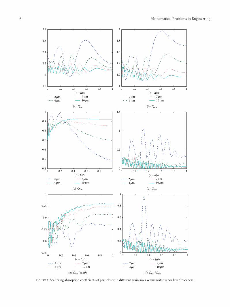
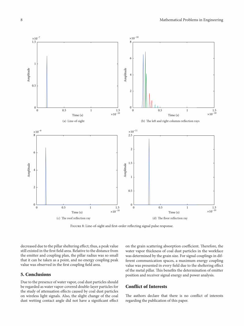
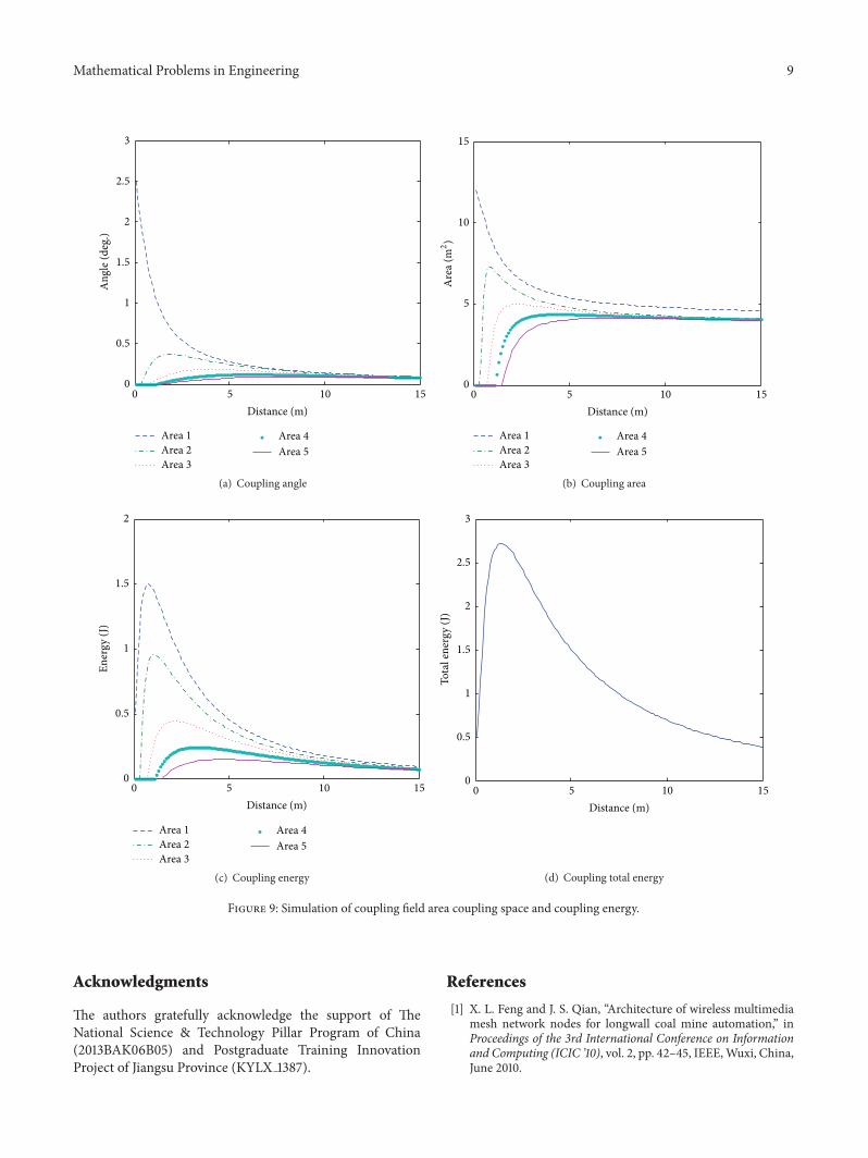