research contributions to the seismic performance … contributions to the seismic performance of...
TRANSCRIPT

Research Contributions to the Seismic Performance of ICF Technology Wall Systems
ANDREEA-TEREZIA MIRCEA1, RUXANDRA CRUTESCU2
1Faculty of Civil Engineering, Technical University of Cluj-Napoca
15 C. Daicoviciu Street, 400020 Cluj-Napoca, ROMANIA
2Faculty of Architecture, 030045 Bucharest, ROMANIA [email protected], [email protected]
Abstract: - Being a very easy to install system, increasing job site efficiency and worker productivity which saves time and money, Insulated Concrete Form (ICF) tilt-up wall systems ensure a more sustainable construction with superior energy efficiency, low material costs, and versatility for the built environment. A research was carried out in order to asses an ICF tilt-up wall system with regard to the requirements of the actual earthquake resistant design of reinforced concrete wall systems and reinforced concrete wall equivalent dual systems. After a preliminary analysis of the constructive provisions, a comprehensive structural analysis program was performed in order to identify the best practices in implementing the system on the market. As variables were considered the design ground acceleration (0.08g, 0.20g and 0.32g), the normalized axial force (0.05, 0.20 and 0.40), the quality of concrete (classes C 16/20 and C 20/25), the effective thickness of the walls (i.e., 150 mm and 200 mm), the longitudinal reinforcing ratio at the ends of the wall (0.005, 0.020 and 0.040) and the type of primary shear wall (i.e., high ductility and medium ductility respectively). The full compliance with the European structural design frame can be reached by two detailing strategies, related to the severity of the actions specific to each site and solution. The results are presented in a synthetic manner, which enables an easy comprehension of the conclusions drawn from the processing of the numerical data. Key-Words: - reinforced concrete, primary shear wall, ductility, non-linear behavior, seismic design 1 Background Once the worldwide sustainable development concept was introduced by the World Commission on Environment and Development (WCED) of the United Nations Organization in 1983, the building sector became a strong engine in promoting and implementing global and local strategies. One result of the research efforts consist in the so called Insulated Concrete Form (ICF) tilt-up wall systems. These systems proved to be costly effective technologies, incorporating thermal mass, insulation, framing, vapor barrier and sound barrier - all in one step. ICF systems ensure a more sustainable construction by greater energy efficiency, enhanced environmental compatibility, reduced labor, low material costs, and versatility. Insulated Concrete Forms (ICFs) are hollow, lightweight forms manufactured by using two expanded polystyrene (EPS) panels which are connected by uniquely designed, high impact polypropylene webs. During construction, the forms are reinforced then filled with fresh concrete resulting stable, durable and sustainable walls. The ICFs (Figure 1) combine the insulating effectiveness of EPS with the thermal mass and structural strength of a reinforced concrete wall, offering a solution that provides structure, insulation, vapour barrier, sound barrier and attachments for drywall and exterior siding in one easy step.
Figure 1. Amvic typical ICF units
WSEAS TRANSACTIONS on INFORMATION SCIENCE and APPLICATIONS Andreea-Terezia Mircea, Ruxandra Crutescu
ISSN: 1790-0832 1240 Issue 10, Volume 7, October 2010
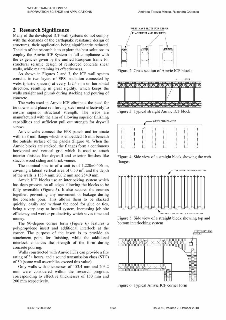
2 Research Significance Many of the developed ICF wall systems do not comply with the demands of the earthquake resistance design of structures, their application being significantly reduced. The aim of the research is to explore the best solutions to employ the Amvic ICF System in full compliance with the exigencies given by the unified European frame for structural seismic design of reinforced concrete shear walls, while maintaining its effectiveness. As shown in Figures 2 and 3, the ICF wall system consists in two layers of EPS insulation connected by webs (plastic spacers) at every 152.4 mm on horizontal direction, resulting in great rigidity, which keeps the walls straight and plumb during stacking and pouring of concrete. The webs used in Amvic ICF eliminate the need for tie downs and place reinforcing steel most effectively to ensure superior structural strength. The webs are manufactured with the aim of allowing superior finishing capabilities and sufficient pull out strength for drywall screws. Amvic webs connect the EPS panels and terminate with a 38 mm flange which is embedded 16 mm beneath the outside surface of the panels (Figure 4). When the Amvic blocks are stacked, the flanges form a continuous horizontal and vertical grid which is used to attach interior finishes like drywall and exterior finishes like stucco, wood siding and brick veneer. The nominal size in of a unit is of 1.220×0.406 m, covering a lateral vertical area of 0.50 m2, and the depth of the walls is 153.4 mm, 203.2 mm and 254.0 mm. Amvic ICF blocks use an interlocking system which has deep grooves on all edges allowing the blocks to be fully reversible (Figure 5). It also secures the courses together, preventing any movement or leakage during the concrete pour. This allows them to be stacked quickly, easily and without the need for glue or ties, being a very easy to install system, increasing job site efficiency and worker productivity which saves time and money. The 90-degree corner form (Figure 6) features a polypropylene insert and additional interlock at the corner. The purpose of the insert is to provide an attachment point for finishing, while the additional interlock enhances the strength of the form during concrete pouring. Walls constructed with Amvic ICFs can provide a fire rating of 3+ hours, and a sound transmission class (STC) of 50 (some wall assemblies exceed this value). Only walls with thicknesses of 153.4 mm and 203.2 mm were considered within the research program, corresponding to effective thicknesses of 150 mm and 200 mm respectively.
Figure 2. Cross section of Amvic ICF blocks
Figure 3. Typical straight Amvic ICF block
Figure 4. Side view of a straight block showing the web flanges
Figure 5. Side view of a straight block showing top and bottom interlocking system
Figure 6. Typical Amvic ICF corner form
WSEAS TRANSACTIONS on INFORMATION SCIENCE and APPLICATIONS Andreea-Terezia Mircea, Ruxandra Crutescu
ISSN: 1790-0832 1241 Issue 10, Volume 7, October 2010
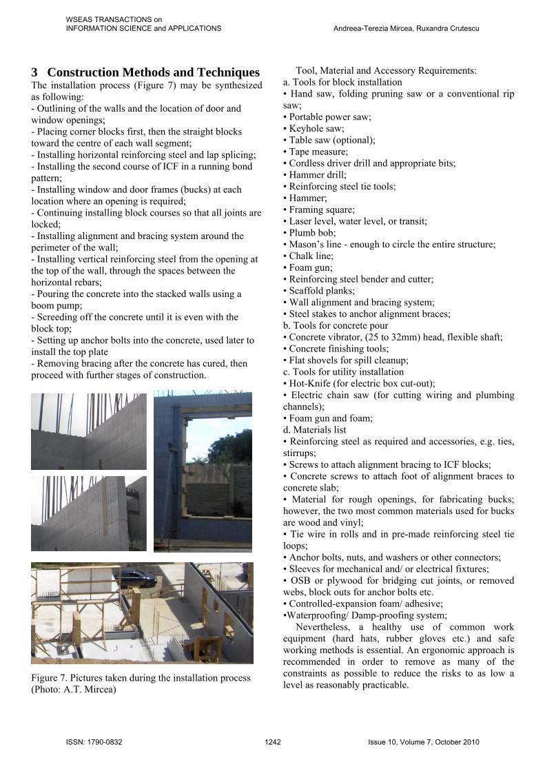
3 Construction Methods and Techniques The installation process (Figure 7) may be synthesized as following: - Outlining of the walls and the location of door and window openings; - Placing corner blocks first, then the straight blocks toward the centre of each wall segment; - Installing horizontal reinforcing steel and lap splicing; - Installing the second course of ICF in a running bond pattern; - Installing window and door frames (bucks) at each location where an opening is required; - Continuing installing block courses so that all joints are locked; - Installing alignment and bracing system around the perimeter of the wall; - Installing vertical reinforcing steel from the opening at the top of the wall, through the spaces between the horizontal rebars; - Pouring the concrete into the stacked walls using a boom pump; - Screeding off the concrete until it is even with the block top; - Setting up anchor bolts into the concrete, used later to install the top plate - Removing bracing after the concrete has cured, then proceed with further stages of construction.
Figure 7. Pictures taken during the installation process (Photo: A.T. Mircea)
Tool, Material and Accessory Requirements: a. Tools for block installation • Hand saw, folding pruning saw or a conventional rip saw; • Portable power saw; • Keyhole saw; • Table saw (optional); • Tape measure; • Cordless driver drill and appropriate bits; • Hammer drill; • Reinforcing steel tie tools; • Hammer; • Framing square; • Laser level, water level, or transit; • Plumb bob; • Mason’s line - enough to circle the entire structure; • Chalk line; • Foam gun; • Reinforcing steel bender and cutter; • Scaffold planks; • Wall alignment and bracing system; • Steel stakes to anchor alignment braces; b. Tools for concrete pour • Concrete vibrator, (25 to 32mm) head, flexible shaft; • Concrete finishing tools; • Flat shovels for spill cleanup; c. Tools for utility installation • Hot-Knife (for electric box cut-out); • Electric chain saw (for cutting wiring and plumbing channels); • Foam gun and foam; d. Materials list • Reinforcing steel as required and accessories, e.g. ties, stirrups; • Screws to attach alignment bracing to ICF blocks; • Concrete screws to attach foot of alignment braces to concrete slab; • Material for rough openings, for fabricating bucks; however, the two most common materials used for bucks are wood and vinyl; • Tie wire in rolls and in pre-made reinforcing steel tie loops; • Anchor bolts, nuts, and washers or other connectors; • Sleeves for mechanical and/ or electrical fixtures; • OSB or plywood for bridging cut joints, or removed webs, block outs for anchor bolts etc. • Controlled-expansion foam/ adhesive; •Waterproofing/ Damp-proofing system; Nevertheless, a healthy use of common work equipment (hard hats, rubber gloves etc.) and safe working methods is essential. An ergonomic approach is recommended in order to remove as many of the constraints as possible to reduce the risks to as low a level as reasonably practicable.
WSEAS TRANSACTIONS on INFORMATION SCIENCE and APPLICATIONS Andreea-Terezia Mircea, Ruxandra Crutescu
ISSN: 1790-0832 1242 Issue 10, Volume 7, October 2010
4 Preliminary Assessment of the ICF System The first concern of the evaluation was how the ICF wall system met the constructive provisions given by the appropriate seismic design detailing rules. The plastic spacers of the ICF wall system are provided with built-in clips for two courses of horizontal rebars with no tying every 400 mm on the vertical direction, which satisfies the provisions of Eurocode 2 [1] with regard to the maximum distance between horizontal rebars. Intermediary horizontal rebars, to sustain shear forces, can be linked between the spacers at 200 mm, by fixing them with steel rod. Thus, the requirements of Eurocode 8 [2] can be satisfied too. The vertical shear reinforcement, undertaking also out-of-plane bending stresses, can be connected to the horizontal rebars by ties or can be fixed between two horizontal rebars positioned in alternate clips. Nevertheless, if in the case of using ordinary formwork a significant quantity of reinforcement may be needed to sustain parasite stresses due to shrinkage of concrete [3], in the case of ICF walls shrinkage potential is substantially reduced. The end longitudinal reinforcement, to sustain in-plane bending moment, is the key issue in detailing for seismic design. It has to provide strength and ductility for the structure. Therefore, rebars have to be restrained by hoops, stirrups or cross-ties spaced at no more than 6 diameters of the rebars, in order to avoid their post-elastic buckling and to provide confinement of the end zones. With regard to the ICF system, it is more convenient to fix the longitudinal rebars by the horizontal shear reinforcement. However, this approach is suitable for gravitational design and/or for detailing the reinforcement above the critical region of the shear wall, but it is not an appropriate design within the critical regions. Thus, two solutions were considered as given below: - The first one suits the situations where no confinement of the end zones is needed, by placing additional stirrups at 400 mm intervals, between the horizontal shear rebars. The cross-section of the end longitudinal rebars should be enough to avoid elastic buckling for fixing distances of 200 mm, which is approximately maximum 10 times the diameter of the rebar. In this case, the longitudinal rebars can be placed one by one, with much care to avoid noticeable deviation from the paths; - The second alternative, suitable for heavy duty walls, presume the introduction of the longitudinal rebars in the formwork already assembled in a spatial tied up case. The distance between the stirrups can be easily computed to avoid post-elastic buckling, and together with the stirrups diameter to provide the adequate confinement ratio.
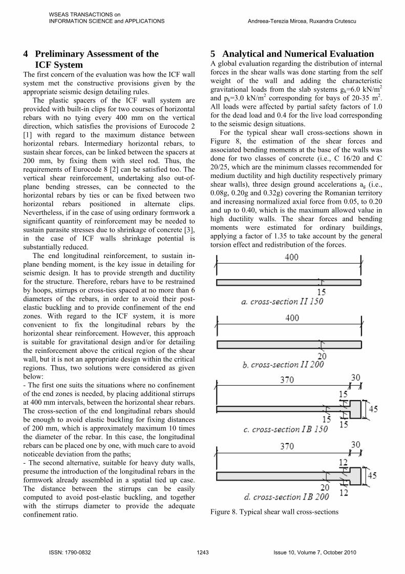
5 Analytical and Numerical Evaluation A global evaluation regarding the distribution of internal forces in the shear walls was done starting from the self weight of the wall and adding the characteristic gravitational loads from the slab systems gk=6.0 kN/m2 and pk=3.0 kN/m2 corresponding for bays of 20-35 m2. All loads were affected by partial safety factors of 1.0 for the dead load and 0.4 for the live load corresponding to the seismic design situations. For the typical shear wall cross-sections shown in Figure 8, the estimation of the shear forces and associated bending moments at the base of the walls was done for two classes of concrete (i.e., C 16/20 and C 20/25, which are the minimum classes recommended for medium ductility and high ductility respectively primary shear walls), three design ground accelerations ag (i.e., 0.08g, 0.20g and 0.32g) covering the Romanian territory and increasing normalized axial force from 0.05, to 0.20 and up to 0.40, which is the maximum allowed value in high ductility walls. The shear forces and bending moments were estimated for ordinary buildings, applying a factor of 1.35 to take account by the general torsion effect and redistribution of the forces.
Figure 8. Typical shear wall cross-sections
WSEAS TRANSACTIONS on INFORMATION SCIENCE and APPLICATIONS Andreea-Terezia Mircea, Ruxandra Crutescu
ISSN: 1790-0832 1243 Issue 10, Volume 7, October 2010

The following values of the behavior factor were considered: - For concrete C 16/20, the values were determined for medium ductility design, q=4.025 for groundfloor buildings and q=4.725 for multi-storey buildings respectively; - For concrete C 20/25, the values were determined for high ductility design, q=5.75 for groundfloor buildings and q=6.75 for multi-storey buildings respectively. The results in the terms of the shear forces and bending moments resulting from structural analysis related to the normalized axial force, the seismic zone and the corresponding number of storeys are presented in Tables 1-4. Given the complexity of the phenomenon of the shear walls subjected to dynamic horizontal actions, non-linear parametric analyses were performed on the set of shear wall cross-sections shown in Figure 8. The analyses were organized in an incremental procedure following the traditional Newton-Raphson scheme, using the numerical formulation proposed by Mircea and Petrovay [4]. No confinement was considered. Table 1. Estimation for C 16/20 and 150 mm thick wall
V'Ed [kN] No. of floors M'
Ed [kNm] νd min max min max min max ag=0.08g
0.05 21.9 15.8 1 3 43.7 95.0 0.20 87.4 63.3 5 12 874.3 1,519.4 0.40 174.9 126.6 10 23 3,497.2 5,824.1
ag=0.20g 0.05 54.6 39.6 1 2 109.3 158.3 0.20 218.6 158.3 4 9 1,748.6 2,848.9 0.40 437.2 316.5 8 19 6,994.6 12,028.1
ag=0.32g 0.05 87.4 63.3 1 2 174.9 253.2 0.20 349.7 253.2 3 8 2,098.4 4,051.7 0.40 699.5 506.5 7 16 9,792.3 16,206.7
Table 2. Estimation for C 20/25 and 150 mm thick wall
V'Ed [kN] No. of floors M'
Ed [kNm] νd min max min max min max ag=0.08g
0.05 19.1 13.9 2 4 76.5 110.8 0.20 76.5 55.4 6 15 917.9 1,661.7 0.40 153.0 110.8 12 29 3,671.5 6,424.7
ag=0.20g 0.05 47.8 34.6 1 3 95.6 207.7 0.20 191.2 138.5 5 12 1,912.3 3,323.0 0.40 382.5 276.9 10 24 7,649.2 13,292.6
ag=0.32g 0.05 76.5 55.4 1 3 153.0 332.3 0.20 305.4 221.5 4 10 2,442.9 4,430.8 0.40 611.9 443.1 9 20 11,014.7 17,723.2
Table 3. Estimation for C 16/20 and 200 mm thick wall V'
Ed [kN] No. of floors M'Ed [kNm] νd min max min max min max
ag=0.08g 0.05 29.1 21.1 2 4 116.6 168.8 0.20 116.6 84.4 7 16 1,632.1 2,701.1 0.40 233.2 168.8 13 31 6,061.9 10,466.8
ag=0.20g 0.05 72.9 52.8 1 3 145.7 316.6 0.20 291.4 211.0 5 13 2,914.4 5,486.5 0.40 582.9 422.1 11 25 12,823.4 21,102.5
ag=0.32g 0.05 116.6 84.4 1 3 233.2 506.5 0.20 466.3 337.6 5 11 4,663.0 7,428.1 0.40 932.6 675.3 9 22 16,786.8 29,711.9
Table 4. Estimation for C 20/25 and 200 mm thick wall
V'Ed [kN] No. of floors M'
Ed [kNm] νd min max min max min max ag=0.08g
0.05 25.5 18.5 2 5 102.0 184.6 0.20 102.0 73.9 8 19 1,631.8 2,806.3 0.40 204.0 147.7 17 39 6,935.3 11,519.8
ag=0.20g 0.05 63.7 46.2 2 4 255.0 369.2 0.20 255.0 184.6 7 16 3,569.6 5,907.8 0.40 509.9 369.2 14 32 14,278.3 23,630.7
ag=0.32g 0.05 102.0 73.9 1 3 204.0 443.1 0.20 408.0 295.4 6 14 4,895.4 8,270.9 0.40 815.9 590.8 12 27 19,581.8 31,902.1
The following parameters were taken into account [5]: - The concrete properties: concrete of classes C 16/20 and C 20/25, with a partial safety factor for the strength of 1.20 (a parabola-rectangle stress-strain relation for concrete under compression was taken into account, no tensile strength and no confinement were considered); - The reinforcing steel properties: mild steel class A, with a characteristic yielding strength fyk of 350 MPa, the Young modulus of 200,000 MPa and the ultimate strain of 14 %; - The longitudinal reinforcing ratio ρv of 0.005, 0.020 and 0.040; - The normalized axial force νd of 0.05, 0.20 and 0.40; - The ground design acceleration of 0.08g, 0.20g and 0.32g. The results of the analyses are shown in Figures 9-20 in the terms of moment-curvature relations for the given cross-section, longitudinal reinforcing ratio and the corresponding normalized axial force.
WSEAS TRANSACTIONS on INFORMATION SCIENCE and APPLICATIONS Andreea-Terezia Mircea, Ruxandra Crutescu
ISSN: 1790-0832 1244 Issue 10, Volume 7, October 2010
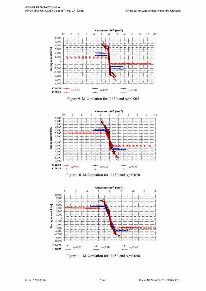
Figure 9. M-Φ relation for II 150 and ρv=0.005
Figure 10. M-Φ relation for II 150 and ρv=0.020
Figure 11. M-Φ relation for II 150 and ρv=0.040
WSEAS TRANSACTIONS on INFORMATION SCIENCE and APPLICATIONS Andreea-Terezia Mircea, Ruxandra Crutescu
ISSN: 1790-0832 1245 Issue 10, Volume 7, October 2010

Figure 12. M-Φ relation for II 200 and ρv=0.005
Figure 13. M-Φ relation for II 200 and ρv=0.020
Figure 14. M-Φ relation for II 200 and ρv=0.040
WSEAS TRANSACTIONS on INFORMATION SCIENCE and APPLICATIONS Andreea-Terezia Mircea, Ruxandra Crutescu
ISSN: 1790-0832 1246 Issue 10, Volume 7, October 2010
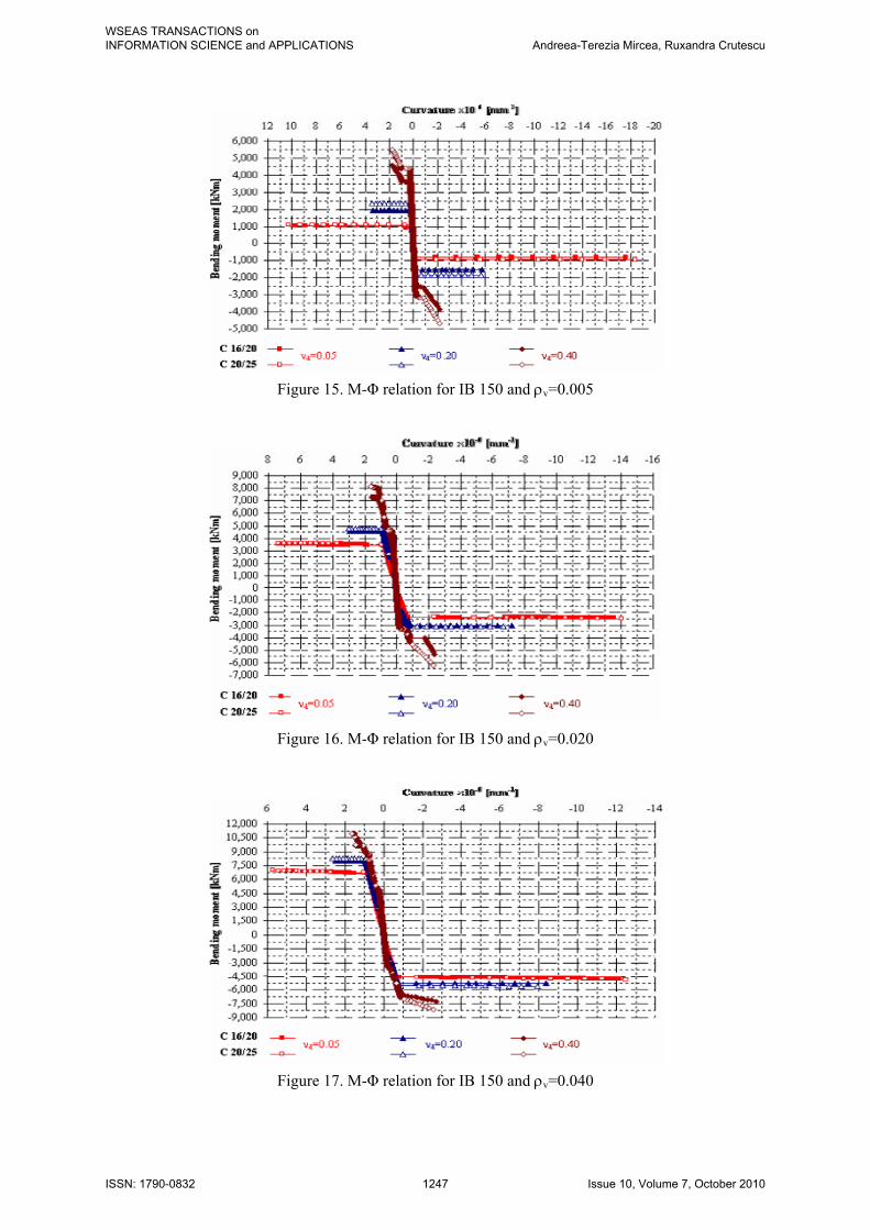
Figure 15. M-Φ relation for IB 150 and ρv=0.005
Figure 16. M-Φ relation for IB 150 and ρv=0.020
Figure 17. M-Φ relation for IB 150 and ρv=0.040
WSEAS TRANSACTIONS on INFORMATION SCIENCE and APPLICATIONS Andreea-Terezia Mircea, Ruxandra Crutescu
ISSN: 1790-0832 1247 Issue 10, Volume 7, October 2010

Figure 18. M-Φ relation for IB 200 and ρv=0.005
Figure 19. M-Φ relation for IB 200 and ρv=0.020
Figure 20. M-Φ relation for IB 200 and ρv=0.040
WSEAS TRANSACTIONS on INFORMATION SCIENCE and APPLICATIONS Andreea-Terezia Mircea, Ruxandra Crutescu
ISSN: 1790-0832 1248 Issue 10, Volume 7, October 2010
A simple comparison of the resistant bending moments with the values of the design bending moments reveals that for low values of the normalized axial force, with a correspondent small number of floors, up to 7 storeys for concrete wall 150 mm thick and up to 9 storeys for concrete walls 200 mm thick respectively, even in the most powerful seismic region of the country, characterized by a ground acceleration of 0.32g, the ordinary primary wall structures behave in the elastic range under the design earthquake spectrum. An elastic behavior is predictable due to the global short cantilever effect of the small structures. However, special attention should be accorded in design because the behavior factors should comply with the structural potential to dissipate the energy induced by an earthquake. Given the above results, energy dissipation can take place only in the coupling beams, and the values of the behavior factor tend to the inferior limit of 1.50 imposed by Eurocode 8 [2]. The elastic behavior is not a quality of the seismic design philosophy. Shear forces increase and the shear failure risk increases. Therefore, for a low number of storeys, it is better to assume a medium ductility design, with even a reduced value of the behavior factor. M(+)
M(-) εcu2 εcu2,c
xu (-)
xu (+)
εcu2,c εcu2 Φu (+)
(-) Φu
plastic spacers (webs)
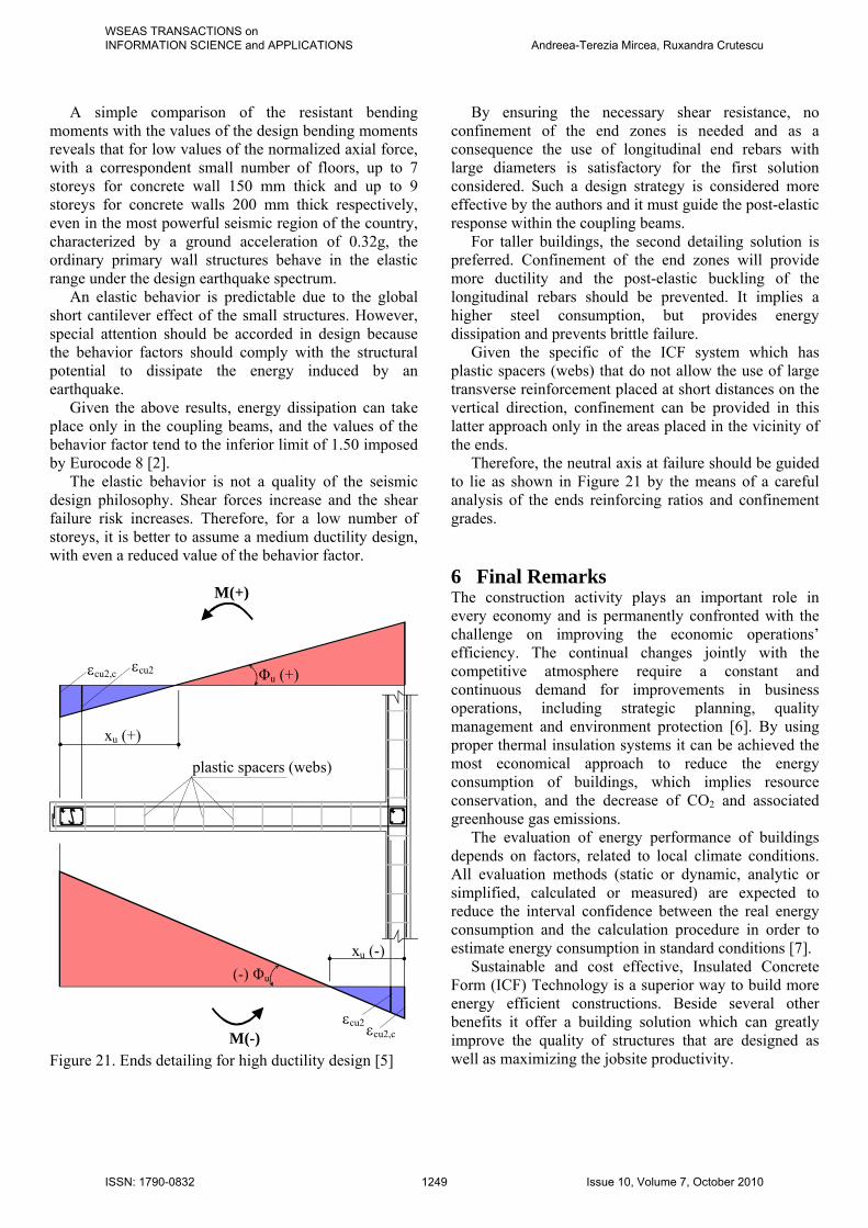
Figure 21. Ends detailing for high ductility design [5]
By ensuring the necessary shear resistance, no confinement of the end zones is needed and as a consequence the use of longitudinal end rebars with large diameters is satisfactory for the first solution considered. Such a design strategy is considered more effective by the authors and it must guide the post-elastic response within the coupling beams. For taller buildings, the second detailing solution is preferred. Confinement of the end zones will provide more ductility and the post-elastic buckling of the longitudinal rebars should be prevented. It implies a higher steel consumption, but provides energy dissipation and prevents brittle failure. Given the specific of the ICF system which has plastic spacers (webs) that do not allow the use of large transverse reinforcement placed at short distances on the vertical direction, confinement can be provided in this latter approach only in the areas placed in the vicinity of the ends. Therefore, the neutral axis at failure should be guided to lie as shown in Figure 21 by the means of a careful analysis of the ends reinforcing ratios and confinement grades. 6 Final Remarks The construction activity plays an important role in every economy and is permanently confronted with the challenge on improving the economic operations’ efficiency. The continual changes jointly with the competitive atmosphere require a constant and continuous demand for improvements in business operations, including strategic planning, quality management and environment protection [6]. By using proper thermal insulation systems it can be achieved the most economical approach to reduce the energy consumption of buildings, which implies resource conservation, and the decrease of CO2 and associated greenhouse gas emissions. The evaluation of energy performance of buildings depends on factors, related to local climate conditions. All evaluation methods (static or dynamic, analytic or simplified, calculated or measured) are expected to reduce the interval confidence between the real energy consumption and the calculation procedure in order to estimate energy consumption in standard conditions [7]. Sustainable and cost effective, Insulated Concrete Form (ICF) Technology is a superior way to build more energy efficient constructions. Beside several other benefits it offer a building solution which can greatly improve the quality of structures that are designed as well as maximizing the jobsite productivity.
WSEAS TRANSACTIONS on INFORMATION SCIENCE and APPLICATIONS Andreea-Terezia Mircea, Ruxandra Crutescu
ISSN: 1790-0832 1249 Issue 10, Volume 7, October 2010

ICF Technology wall systems are constructed using reinforced concrete, able to provide a highly durable and functional solution [8], which increases strength and maximizes resistance to natural disasters. The combination of materials: expanded polystyrene (EPS) insulation and concrete thermal mass minimizes temperature fluctuations by absorbing and storing heat. They are also very flexible in design: making curved or straight walls easily obtainable. In addition, exterior and interior wall coverings are easily attached, considerably improving the structure’s appearance. Insulated Concrete Form systems are typically used for the structure’s exterior walls from foundation to the top plate, including basements, but they can also be used in combination with conventional wood frame or panel construction. ICF technology wall systems are valuable solutions in sustainable design. Even so, the application of each system should be made in accordance with its potential to comply with performance based design exigencies - obtaining structures, where the seismic vulnerability can be inferred by means of existing codes and analysis methodologies [9]. The research concluded, as shown above, that the Amvic ICF System allows a reinforcing detailing able to satisfy all structural demands, providing a reliable structural and insulation solution for buildings with a large variety of functional needs. Acknowledgment This research was carried out with the support of the Amvic Romania Ltd. and Passivhaus Institute Ltd. from Bucharest. The authors wish to express their appreciation for the sustain of their leading teams regarding this work. References: [1] EN 1992-1-1, Eurocode 2: Design of concrete structures - Part 1: General rules and rules for buildings. [2] EN 1998-1, Eurocode 8: Design of structures for earthquake resistance Part 1: General rules, seismic actions and rules for buildings. [3] C. Mircea, Overview upon restrained shrinkage cracking of RC structures, Proceedings of the International Conference on Concrete Solutions, Padua, Italy, 22-25 June 2009, Taylor & Francis Group, London, ISBN 978-0-415-55082-6, pp. 171-177. [4] C. Mircea & G. Petrovay, New Approach in Non-Linear Sectional Analysis of RC and PC Members, Proceedings of FIB International Symposium “Keep Concrete Attractive”, Budapest, Hungary, 23-25 of May 2005, vol. II, pp. 736-741.
[5] A.T. Mircea, R. Crutescu, Analysis of an ICF Technology Shear Walls System, Proceedings of the 3rd WSEAS International Conference on Engineering Mechanics, Structures, Engineering Geology (EMESEG '10), Book: “Latest Trends on Engineering Mechanics, Structures, Engineering Geology”, Corfu Island, Greece, 22-24 July 2010, ISSN: 1792-4294, ISBN: 978-960-474-203-5 pp. 110-115. [6] D. Kralj, U. Ogrin, J. Krope, Innovating of Management in Construction Industry as Integral Part of Environment Protection, Proceedings of the WSEAS International Conference on Environment, Ecosystems and Development, Venice, Italy, 2-4 November, 2005, ISBN: 960-8457-37-8, pp. 72-77. [7] L. Tronchin, Real consumption and numerical methodologies in energy performance of buildings, Proceedings of the 5th IASME/WSEAS International Conference on Heat Transfer, Thermal Engineering and Environment, Athens, Greece, 25-27 August, 2007, ISSN: 1109-2769, ISBN: 978-960-6766-00-8, pp.314-319. [8] A.T. Mircea, A Frequent Complain: Cracking of Concrete in Slabs-on-Ground, Proceedings of the 3rd WSEAS International Conference on Urban Planning And Transportation (UPT’10), Book: Latest Trends on Urban Planning And Transportation, Corfu Island, Greece, 22-24 July 2010, ISSN: 1792-4286, ISBN: 978-960-474-202-2, pp.66-69. [9] M. Mosoarca, V. Gioncu, Assessment and mitigation procedures for historical buildings situated in seismic areas, Proceedings of the WSEAS International Conference on Risk Management, Assessment and Mitigation, Bucharest, Romania, 20-22 April 2010, ISSN: 1790-2769, ISBN: 978-960-474-182-3, pp. 27-32.
WSEAS TRANSACTIONS on INFORMATION SCIENCE and APPLICATIONS Andreea-Terezia Mircea, Ruxandra Crutescu
ISSN: 1790-0832 1250 Issue 10, Volume 7, October 2010