seismic performance assessment of prefabricated …
TRANSCRIPT

Uludağ University Journal of The Faculty of Engineering, Vol. 25, No. 1, 2020 RESEARCH
DOI: 10.17482/uumfd.670347
247
SEISMIC PERFORMANCE ASSESSMENT OF PREFABRICATED
INDUSTRIAL BUILDINGS WITH SEMI-RIGID CONNECTIONS
Zeynep FIRAT ALEMDAR *
Received: 04.01.2020; revised: 25.02.2020; accepted: 28.03.2020
Abstract: In this study, the performances of 120 precast factory buildings consisting of five different types
in an industrial area in Istanbul, Turkey are examined before and after the applications of retrofit methods
through nonlinear time history analyses. The factory buildings were constructed and became operational
before the 1999 Kocaeli earthquake. Following the earthquake, they were operationally safe, however, after
the evaluation according to the 1998 Turkish Earthquake Code (TEC), most of the connections were found
to be inadequate. The buildings were retrofitted by using bolted steel plates in the connection regions and
diagonal steel braces in 2005. A detailed finite element model of the connection was developed before and
after the retrofit methods and the behavior of the region was implemented in the three-dimensional models
of the structures. The buildings were analyzed according to the Turkish Earthquake Code 2007. The number
of damaged beams by the TEC-2007 was higher than the rate of damaged beams per the FEMA-356. In
three-dimensional performance analysis of buildings, the importance of examination of connection regions
and implementing the results to the full building model were emphasized. The performance of the building
were increased by reducing the distance between the plane frames in the longitudinal direction and the
beam length in the transverse direction.
Keywords: Precast factory building, Beam-column connection, Finite element model, Nonlinear behavior,
Performance assessment
Yarı-Rijit Bağlı Prefabrik Endüstriyel Binaların Deprem Performansının Değerlendirilmesi
Öz: Bu çalışmada, İstanbul'da bir sanayi bölgesinde beş farklı tipten oluşan 120 adet prefabrik fabrika
binasının performansları güçlendirme yöntemlerinin uygulanmasından önce ve sonra, zaman tanım
alanında doğrusal olmayan analizler ile incelenmiştir. Fabrika binaları 1999 Kocaeli depreminden önce inşa
edilmiş ve çeşit endüstrilerde faaliyete geçmiştir. Kocaeli depreminin ardından binalar işletme açısından
güvenli kabul edilmiş, ancak 1998 Türk Deprem Yönetmeliği (TDY) koşulları açısından
değerlendirildikten sonra kiriş-kolon bağlantılarının çoğunun yetersiz kaldığı tespit edilmiştir. Binalar 2005
yılında birleşim bölgelerinde bulonlu çelik levhalar ve yapı genelinde diyagonal çelik çubuklar kullanılarak
güçlendirilmiştir. Bu çalışmada farklı güçlendirme yöntemlerinin uygulanmasından önce ve sonra kiriş-
kolon bağlantı bölgesinin detaylı bir sonlu eleman modeli geliştirilmiş ve bölgenin davranışı yapıların üç
boyutlu modellerinde dikkate alınmıştır. Türk Deprem Yönetmeliği 2007 kurallarına uygun olarak fabrika
binaları analiz edilmiştir. Güçlendirme tekniklerinin ve genel plan boyutlarının performans seviyeleri
üzerindeki etkileri tespit edilmiştir. Analizler sonucunda, TDY 2007 kriterlerine göre hasar gören kiriş
elemanları sayısı FEMA-356 koşullarına göre hesaplanan elemanlardan daha fazla bulunmuştur. Yapıların
üç boyutlu performans analizlerinde, birleşim bölgelerinin detaylı incelenmesi ve tüm yapı modeline
davranışın aktarılması gerektiğinin önemi vurgulanmıştır. Yapıların boyuna doğrultuda düzlem çerçeveler
* Yıldız Teknik Üniversitesi, Davutpaşa Kampüsü, İnşaat Mühendisliği Bölümü, Esenler, İstanbul 34220
İletişim Yazarı: Zeynep Fırat Alemdar ([email protected])

Alemdar Z. F.: Seismic Performance Assessment Of Prefabricated Industrial Buildings With Semi-Rigid.
248
arası uzunluğunun ve kısa doğrultudaki kiriş uzunluklarının azaltılması ile yapı performansının arttığı
görülmüştür.
Anahtar Kelimeler: Prefabrik endüstriyel bina, Kiriş-kolon birleşimi, Sonlu elemanlar modeli, Doğrusal
olmayan davranış, Performans değerlendirme
1. INTRODUCTION
Precast concrete structures have fundamental advantages over cast-in-place reinforced
concrete structures: increased speed of construction, improved quality control, efficient use of
materials, and reduced site formwork and labor (Yee et al., 2011). After establishing the
Prestressed Concrete Institute in 1954, many buildings and structures such as parking garages,
office buildings, and bridges have been designed and built using precast/prestressed concrete in a
vast number of countries (Xue and Yang, 2010). After the 1994 Northridge and 1995 Kobe
earthquakes, however, the failure of the precast concrete beam to column connections caused
significant concerns for these systems in regions of high seismicity. Field observations in the
aftermath of the 1998 Adana-Ceyhan (Adalier and Aydingun, 2001) and 1999 Kocaeli and Duzce
earthquakes (Saatcioglu et al., 2001; Arslan et al., 2006, Sezen and Whittaker, 2006) also showed
that inadequate stiffness and strength and/or problems caused by insufficient connection detailing
raised the major structural deficiencies in RC precast industrial facilities. Posada and Wood
(2002) reported that the damage level of the industrial buildings are mainly influenced by the drift
demand and the drift capacity of the buildings. The damage of precast structures in Sakarya was
more pronounced due to the drift demand invoked by the soft soil conditions, as compared to the
no damage in Gebze where the soil is basically stiff clay to rock.
Several different types of connections have been used for the last two decades to connect the
beams to the columns, including welded plate and billet, high-performance fiber-reinforced
cement composite, hybrid post-tensioning frame, precast reinforced concrete, and specially
developed bolted connection systems (Elliot et al., 1998; Vasconez et al., 1998; Priestley et al.,
1999; Vidjeapriya and Jaya, 2013). The steps of the proper design and detailing of connection
system are well defined in the literature (ACI 318R-95; NEHRP 2001; Fib 2003; Englekirk, 2003;
Bournas et al., 2013; Bournas et al., 2014). Also, according to the TEC (2007) requirement, all
moment-resisting connections in precast concrete structures should maintain similar rigidity,
strength, energy dissipation and ductility with the monolithic system behavior under cyclic
loadings occurred during earthquakes.
Considerable amount of experimental and analytical studies have been carried out to
investigate the seismic performance of precast beam-column joints subjected to reversed cyclic
loading simulating severe earthquake action and develop retrofitting techniques for vulnerable
existing precast joints (Baysal, 1991; Ersoy and Tankut, 1993; Oztug, 1994).
Two types of structural damage were frequently observed: flexural hinges at the base of the
columns and pounding of the precast elements at the roof level after 1999 Kocaeli and Duzce
earthquakes (EERI, 2000). In contrast to the precast frames used in Turkey, concrete tilt-up wall
panels are commonly used to construct one-story industrial structures in the US. The seismic
performance of low-rise industrial buildings in Turkey and the US were compared. Although the
structural systems were very different, both are vulnerable to earthquake damage. Rehabilitation
schemes used in southern California to improve the performance of tilt-up structures were
proposed as an option for Turkish construction (Wood, 2003).
The full-scale test results of three-story precast building studied in the framework of the
SAFECAST project were presented (Negro et al., 2013; Bournas et al., 2013). The effect of two
types of beam–column connections on the seismic behavior was evaluated. They were the pinned
beam–column joints and a new connection system with dry connections. It was concluded that
the new beam-to-column connection system is a viable solution toward enhancing the response

Uludağ University Journal of The Faculty of Engineering, Vol. 25, No. 1, 2020
249
of precast RC frames subjected to seismic loads, in particular when the system is applied to all
joints and quality measures are enforced in the execution of the joints.
The main vulnerabilities observed in precast industrial buildings during Emilia 2012
earthquakes (Belleri et al., 2015) were related to inadequate connection strength and ductility or
to the absence of mechanical devices. The most severe type of damage was the loss of support
and consequent fall of structural and non-structural members. Seismic performance of industrial
facilities in Italian territory was investigated according to European Building Code and retrofit
solutions were proposed to improve the local and global response of precast industrial buildings.
Two distinct exterior beam–column connections made of normal-strength concrete were
subjected cyclic displacement reversals in order to obtain information on strength, stiffness and
ductility characteristics of the connection details as a part of SAFECAST at Structural and
Earthquake Engineering Laboratory of Istanbul Technical University (ITU). The preliminary
design of the joints has been updated during the tests based on the damages observed, thus a set
of improved specimens have also been built and tested, and a relatively better performance is
obtained expectedly. The industrial and residential types of connections showed stable load–
displacement cycles with high energy dissipation up to structural drift of 2%, though a significant
level of pinching and deterioration of the critical section have occurred at around 3% drift level.
The tested specimens have been numerically modeled to calibrate the analytical tools, and a
satisfactory approximation has been obtained between experimental and numerical results
(Yuksel et al., 2015).
A new dry mechanical beam-column joint for fully restrained moment connections of precast
concrete frames were proposed and tested under cyclic loadings (Nzabonimpa et al., 2017). The
new joint consisted of extended steel plates with bolts designed to transfer tension and
compression forces, providing fully restrained moment connection at the joint. Experimental and
analytical investigations were performed to verify the structural behavior of the connections for
concrete components. The connections were expected to be utilized in modular offsite
constructions. In the later study, detailed nonlinear finite element analyses of the mechanical joint
were performed to reproduce the experimental response of the joints (Nzabonimpa et al., 2017).
Nonlinear finite element model of the precast beam column joints was based on concrete damaged
plasticity. The results of the analyses uncovered the failure modes including the deformations of
beam end plates and the concrete damage of the novel connections. Experimental investigations
of three full-scale test specimens and analytical results were in good agreement despite its
complex geometry and complexity of the mechanical joint.
The main objective of the study is to investigate the performances of 120 precast structures
consisting of five different types in an industrial area in Istanbul, Turkey before and after the
applications of retrofit methods. Detailed FE models of the welded beam-column connection
region of the structures are developed before and after retrofit and the results are incorporated as
an input to represent the joint region in the three-dimensional (3-D) models of the precast concrete
structures. Two different strengthening methods applied to the precast structures after the 1999
Kocaeli earthquakes are taken into account to decrease the effect of the primary and secondary
forces acting on the connection regions and consequently to reduce the maximum deformation of
the precast structures. Nonlinear time-history analyses are conducted to observe the behavior and
consequently the performance of the structures before and after the retrofit according to
deformation limits defined in the TEC-2007. The effects of the retrofitting techniques and the
overall plan dimensions on the performance levels are quantified. The performance levels before
and after retrofitting are also compared and discussed. Based on the findings of this study,
recommendations to the designer for the selection of plan dimensions and span lengths are
provided based on the differences between the structures.

Alemdar Z. F.: Seismic Performance Assessment Of Prefabricated Industrial Buildings With Semi-Rigid.
250
2. EVALUATION OF THE NON-RETROFITTED PRECAST STRUCTURES
2.1. Geometry and Reinforcement Detailing
Five different types of bare/non-retrofitted precast structures are investigated in this part of
the study (Fig. 1). The structure types are denoted as A, B, and C depending on the number of
span along the transverse directions of the buildings. Details related to these structures are given
in Table 1. The structures generally consisted of one mezzanine floor in the production part of the
building and two mezzanine floors in the office areas. The columns of all investigated structures
lay on individual spread footings which are connected using cast-in-place tie beams both in the
longitudinal and transverse directions. The structures are located in the first seismic zone having
an effective strong motion coefficient of 0.40, and the soil class is Z2 according to TEC-2007,
which is similar to class B in FEMA 356 (2000) guideline.
Figure 1: Google image of the studied area (Type A1, A2, B1, B2, and C)
Table 1. Structural properties of the precast buildings
Type
A1
Type
A2
Type
B1
Type
B2
Type
C
Number of span in X
direction
3 3 2 2 4
Number of span in Y
direction
7 6 4 5 7
Span length in X
direction (m)
6.67 6.67 5.00 7.00 7.50
Span length in Y
direction (m)
7.5 7.5 7.5 6.6 7.5
Story Height (m) 11.0 10.2 7.0 10.4 10.5
A typical plane frame in the investigated precast structures consists of a single beam and two
columns as shown in Fig.2. All columns and beams have the same cross-sectional dimensions of

Uludağ University Journal of The Faculty of Engineering, Vol. 25, No. 1, 2020
251
0.30×0.55 m and 0.30×0.70 m in all the structures, respectively. Only at the corbel region, the
beams’ cross-sectional dimensions are reduced to 0.30×0.40 m. Each column has 16 longitudinal
reinforcements which consist of 4Ø20, 4Ø22, 4Ø24, and 4Ø26 mm bars that all result in 4%
reinforcement ratio. At both ends of the beams and the upper face of the corbels, steel plates were
anchored. Through welding these plates, the precast beams and columns were joined during the
construction. In the structures studied, precast columns with corbels were connected to
prefabricated beams by welding these steel plates between the corbels and the beams. Roof trusses
are composed of beams with cross-sectional dimensions of 0.30×0.50 m. Along the Y directions
of the structures, the roof trusses are connected using ridge beams. The roof trusses are connected
to the columns by using 2Ø22 mm bolts in the connection regions as shown in Fig. 3. The flooring
systems consist of ready-made 0.15 m thick hollow-core precast slabs which are standing freely
on the upper faces of the beams. Additionally, 0.05 m concrete topping was poured during the
construction.
Figure 2: A typical plane frame in precast structures a. Whole view b. Details of the connections

Alemdar Z. F.: Seismic Performance Assessment Of Prefabricated Industrial Buildings With Semi-Rigid.
252
Figure 3: Connection region of the roof truss
2.2. Materials
In the projects of the precast concrete structures, the characteristic compressive strength,
elasticity modulus and density of the concrete are given as 30 MPa, 32 GPa and 2400 kg/m3,
respectively. The yield stress, elasticity modulus and density of the reinforcing steel are provided
as 420 MPa, 200 GPa and 7850 kg/m3, respectively. Yield strength and elasticity modulus of the
steel plates used for anchorage and the bolts are 360 MPa and 200 GPa, respectively. The
characteristic material properties are taken into account in the analyses.
2.3. Loadings
Dead and live loads were considered in the design of the structures. These loads were
calculated as per the requirements of the Turkish Standard (TS-498, 1997). Live loads on the
office floors and production levels and the roof and roof cover loads were taken as 350, 500, 80
and 8 kg/m2, respectively.
2.4. Modeling of the Connection Region
A proper behavioral representation of the connection region is needed since the actual
behavior of the region considerably affects the overall behavior of the precast concrete structures
under lateral loading. In this context, the beam-column joint region of the considered structures
is defined in detail to obtain the moment-rotation relation for the beam in the connection area
using ABAQUS FE (2015) program. The model consists of a column, a beam, two steel anchorage
plates and the weld around the edges of the plates. The longitudinal reinforcement and transverse
reinforcement in the beam are also modeled. In the finite element model, the anchorage steel
plates overlapped each other are connected to the upper face of the corbel and the lower face of
the beam end by welding the edges of the plates as shown in Fig. 4. The concrete material in the
column and beam members is modeled using the Damage-Plasticity Model implemented in
ABAQUS program as this model can represent the inelastic behavior of concrete both in tension
and compression as well as damage characteristics. In this material model, concrete tension
stiffening and concrete compression hardening properties are used. Also, the concrete tension and

Uludağ University Journal of The Faculty of Engineering, Vol. 25, No. 1, 2020
253
compression damage options are defined to specify tensile and compressive stiffness degradation
damage according to the program manual. A biaxial steel model is defined to simulate the
behavior of both the longitudinal reinforcing and structural steel. In this model, the isotropic
hardening rule is followed under cyclic loading.
The column, beam, steel plates and welding are modeled using 3D continuum 8-node brick
elements, whereas longitudinal reinforcement and transverse steel hoops in the beam element are
defined using 1D 2-node linear truss elements. Approximately 9000 elements are utilized in the
model. Both ends of the column are defined as fixed. The free end of the beam is unconstrained,
whereas the other end where the beam meets the column is constrained. Initially, there is a 5 mm
gap between the column corbel and the beam. Hard contact interaction is defined between the
corbel and beam surface after the 5 mm gap is closed due to bending. Uniform pressure surface
load on the top of the beam and uniform shear load on the cross-section of the beam are obtained
under the static loading of the 3-D FE model of the structures in SAP2000 and applied in the
ABAQUS FE model. The deformed shape of the connection region is given in Fig. 5 after the
loadings. First, the vertical displacement at the free end of the beam is obtained from the static
analysis of the connection region. Then, the rotation values are calculated as a ratio of the beam
free end displacement to the distance between the free end of the beam and the axis of the column.
The moment values for the constrained end of the beam are computed using the pressure surface
load and uniform shear load on the beam at the center point where the beam is located on the
corbel. Consequently, the moment-rotation relationship for the beam in the connection region is
acquired. The moment-rotation values are incorporated to define the semi-rigid connection
properties of the beam cross-sections where the beam set on the corbel part of the column in the
full 3-D model of each structure to be analyzed.
Figure 4:
The beam-column connection region; a. Dimensions of the region b. Detailed model

Alemdar Z. F.: Seismic Performance Assessment Of Prefabricated Industrial Buildings With Semi-Rigid.
254
Figure 5:
Deformed shape of the connection region
2.5. Nonlinear Dynamic Analysis of the Precast Concrete Structures
Nonlinear time-history analyses of A, B and C type of precast structures are conducted
through 3-D FE modeling using the SAP2000 FE Software (2018) as per the requirements of
TEC-2007. The models of the structures consist of precast columns, beams, floor systems, roof
trusses and ridge beams. As a reference, the FE models of type A1 and C structures are shown in
Fig. 6. In the construction of the models, all dimensions, material properties and details are taken
from the design projects of the structures. Mander concrete model (Mander et al., 1988) with
Takeda hysteresis is defined for the behavior of concrete materials while kinematic hardening
properties with cyclic strain softening is defined for the steel material. At the connection region,
the beam ends on the corbel regions are partially constrained due to semi-rigid connection, and
the beam ends connected to the columns directly are defined as fixed. The column ends on the
connections and as well as at the foundation level are modeled as fixed to describe the moment-
resisting connections. The partial fixities (semi-rigid connection) for beams are achieved by
providing nonlinear rotational springs whose stiffness values are calculated from the described
moment-rotation relationship above. Lumped plastic hinge properties of the beams and columns
are determined by using XTRACT sectional analysis program (2004) with confined and
unconfined concrete material properties defined by Mander Model and the stress-strain behavior
of the steel material defined with a strain hardening branch. The damage mechanism of the cross-
sections of the beam and column members in the FE model is specified by utilizing the plastic
hinge characteristics according to TEC-2007. For all the columns, axial force-moment interaction
surfaces for different axial forces are also defined in the models. The connections between the
roof beams and columns are defined as rigid. The ridge beam ends are defined as pins. All other
sections of the structural members are modeled with linear elastic properties both for the concrete
and reinforcing steel.
Uludağ University Journal of The Faculty of Engineering, Vol. 25, No. 1, 2020
255
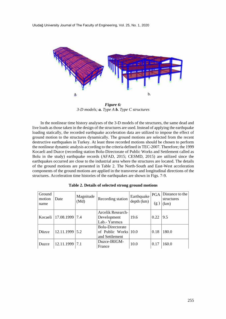
Figure 6:
3-D models; a. Type A b. Type C structures
In the nonlinear time history analyses of the 3-D models of the structures, the same dead and
live loads as those taken in the design of the structures are used. Instead of applying the earthquake
loading statically, the recorded earthquake acceleration data are utilized to impose the effect of
ground motion to the structures dynamically. The ground motions are selected from the recent
destructive earthquakes in Turkey. At least three recorded motions should be chosen to perform
the nonlinear dynamic analysis according to the criteria defined in TEC-2007. Therefore; the 1999
Kocaeli and Duzce (recording station Bolu-Directorate of Public Works and Settlement called as
Bolu in the study) earthquake records (AFAD, 2015; CESMD, 2015) are utilized since the
earthquakes occurred are close to the industrial area where the structures are located. The details
of the ground motions are presented in Table 2. The North-South and East-West acceleration
components of the ground motions are applied in the transverse and longitudinal directions of the
structures. Acceleration time histories of the earthquakes are shown in Figs. 7-9.
Table 2. Details of selected strong ground motions
Ground
motion
name
Date Magnitude
(Md) Recording station
Earthquake
depth (km)
PGA
(g )
Distance to the
structures
(km)
Kocaeli 17.08.1999 7.4
Arcelik Research-
Development
Lab.- Yarımca
19.6 0.22 9.5
Düzce 12.11.1999 5.2
Bolu-Directorate
of Public Works
and Settlement
10.0 0.18 180.0
Duzce 12.11.1999 7.1 Duzce-IRIGM-
France 10.0 0.17 160.0

Alemdar Z. F.: Seismic Performance Assessment Of Prefabricated Industrial Buildings With Semi-Rigid.
256
Figure 7:
Acceleration time histories of Kocaeli earthquake
Figure 8:
Acceleration time histories of Düzce (Bolu) earthquake
Figure 9:
Acceleration time histories of Düzce (IRIGM) earthquake

Uludağ University Journal of The Faculty of Engineering, Vol. 25, No. 1, 2020
257
2.6. Performance assessment of the precast concrete structures
The performance evaluations of the types A, B, and C precast structures are determined as
per the criteria of the TEC-2007. From the results of the time history analyses, the plastic hinge
locations along the X (transverse) and Y (longitudinal) directions of the buildings under each
earthquake record are obtained. Plastic hinges occurred in the type A1 structures after Kocaeli
and Bolu earthquake analyses are shown in Fig. 10. The plastic hinges are generally concentrated
on the beam elements on the first floor. There are no plastic deformations observed in the columns
due to the strong column-weak beam design and soil type in the industrial area. The strain values
in the concrete and reinforcing steel corresponding to total maximum curvature of the cross-
section during the earthquake motions are calculated and compared with criteria specified in TEC-
2007 to assess the performance levels of each damaged beam member.
Figure 10:
Plastic hinges in the type A1 structure after; a. Kocaeli b. Bolu earthquake
For ductile reinforced concrete members, three limit conditions are defined in the TEC-2007
similar to Applied Technology Council-40 (1996), FEMA-356, and FEMA-440 (2005)
guidelines. The limits are immediate occupancy (IO), life safety (LS), and collapse prevention
(CP) conditions. In type A1 and C structures, more than 10% of the beams on any floor during
Kocaeli and Bolu earthquake motions got damaged in the advanced damage zone defined in TEC-
2007 while there is no beam damaged under Duzce ground motion. The performances of the
structures are determined as LS level for Kocaeli and Bolu earthquakes, however; the
performance level is accepted as IO level for Duzce motion according to the requirements in TEC-
2007. The final performance level should be selected by taking the worst performance of a
structure after the time history analyses with the three different ground motions as specified in
TEC-2007. Therefore, the performances of type A1 and C structures are accepted as LS level.
There is no damage observation in type B1 building under Kocaeli, Bolu and Duzce ground
motions. Therefore the performance of the building B1 is considered as IO level. The performance
levels of type A2 and B2 structures are within the IO limit under Kocaeli motion since there are
no beams in the advanced damage zone, whereas there are more than 10% of the beams in the
advanced damage zone under Bolu motion the performances of the structures are in the LS level.
Alemdar Z. F.: Seismic Performance Assessment Of Prefabricated Industrial Buildings With Semi-Rigid.
258
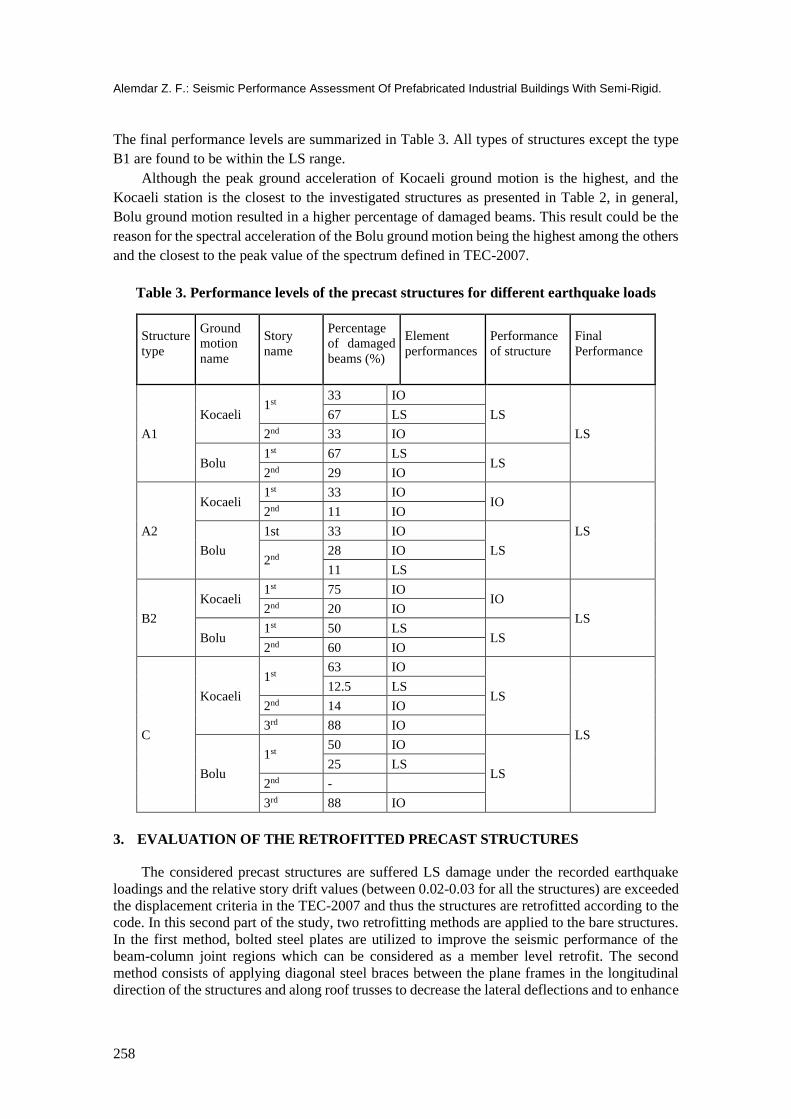
The final performance levels are summarized in Table 3. All types of structures except the type
B1 are found to be within the LS range.
Although the peak ground acceleration of Kocaeli ground motion is the highest, and the
Kocaeli station is the closest to the investigated structures as presented in Table 2, in general,
Bolu ground motion resulted in a higher percentage of damaged beams. This result could be the
reason for the spectral acceleration of the Bolu ground motion being the highest among the others
and the closest to the peak value of the spectrum defined in TEC-2007.
Table 3. Performance levels of the precast structures for different earthquake loads
Structure
type
Ground
motion
name
Story
name
Percentage
of damaged
beams (%)
Element
performances
Performance
of structure
Final
Performance
A1
Kocaeli 1st
33 IO
LS
LS
67 LS
2nd 33 IO
Bolu 1st 67 LS
LS 2nd 29 IO
A2
Kocaeli 1st 33 IO
IO
LS
2nd 11 IO
Bolu
1st 33 IO
LS 2nd
28 IO
11 LS
B2
Kocaeli 1st 75 IO
IO
LS 2nd 20 IO
Bolu 1st 50 LS
LS 2nd 60 IO
C
Kocaeli
1st 63 IO
LS
LS
12.5 LS
2nd 14 IO
3rd 88 IO
Bolu
1st 50 IO
LS 25 LS
2nd -
3rd 88 IO
3. EVALUATION OF THE RETROFITTED PRECAST STRUCTURES
The considered precast structures are suffered LS damage under the recorded earthquake
loadings and the relative story drift values (between 0.02-0.03 for all the structures) are exceeded
the displacement criteria in the TEC-2007 and thus the structures are retrofitted according to the
code. In this second part of the study, two retrofitting methods are applied to the bare structures.
In the first method, bolted steel plates are utilized to improve the seismic performance of the
beam-column joint regions which can be considered as a member level retrofit. The second
method consists of applying diagonal steel braces between the plane frames in the longitudinal
direction of the structures and along roof trusses to decrease the lateral deflections and to enhance

Uludağ University Journal of The Faculty of Engineering, Vol. 25, No. 1, 2020
259
the strength of the structures. Since the braces provide load paths to transfer the lateral loading,
the second retrofitting method is considered as a system-level retrofit. Type A and C structures
are strengthened by using both methods, and type B structures are retrofitted by using the second
method only.
The additions to upgrade the bare structures are the steel braces, steel plates and bolts to
retrofit the connection regions and the whole structures. Steel braces are hollow circular cross-
sections having 102, 114, 140, 168, 178, and 218 mm diameter. The thicknesses of the braces are
5 and 6 mm. Steel plates on the beam-column connection regions are 550x725x12 mm. Steel
plates are connected to the precast beams and columns by using 4 grade 8.8 M16 bolts.
3.1. Modeling of the retrofitted connection region
The FE model of the retrofitted connection region is constructed using ABAQUS FE
program by adding steel plates and bolts to the FE model of the bare connection region as shown
in Fig. 11(a). The same boundary conditions, concrete and steel material constitutive relationships
as those utilized in the earlier model are implemented.
Steel plates and bolts are constrained to the precast column and beam in the new FE model.
The column, beam, steel plates, welding and bolts are modeled using 3D continuum 8-node brick
elements, whereas longitudinal reinforcement and transverse steel hoops in the beam element are
defined using 1D 2-node linear truss elements. After the static loadings, the deformed shape of
the connection region after retrofit is given in Fig. 11(b). The moment-rotation relation for the
beam in the retrofitted connection region is obtained under the static loading using the same
procedure as described above. The comparison between the moment-rotation relations of the
beam before and after retrofitting is shown in Fig. 12. The moment capacity of the beam in the
retrofitted model is almost doubled up after applying the steel plates and the bolts. The moment-
rotation values are used to represent the semi-rigid connection properties of the beam cross-
sections as defined in the analysis of the bare structures. The flexural rigidity (rotational spring
stiffness) of the beam is then assigned to the beams in the full 3-D model of each retrofitted
structure.
Figure 11:
The beam-column connection region after strengthening; a. FE model b. Deformed shape

Alemdar Z. F.: Seismic Performance Assessment Of Prefabricated Industrial Buildings With Semi-Rigid.
260
Figure 12:
Moment-rotation relations of the beam before and after strengthening
3.2. Nonlinear seismic analysis of the retrofitted precast structures
Three-dimensional FE models of the types A, B, and C retrofitted precast structures are
developed using the SAP2000 FE program. The steel braces are added into the FE models of the
bare structures to construct the retrofitted models of the buildings. The FE model of type A1
retrofitted structure is shown in Fig. 13(a) as a reference. Material properties, structural modeling,
analysis procedures and loadings are taken the same as described in the FE model of the bare
structures. Plastic hinges occurred in the type A1 structure after Kocaeli earthquake are shown in
Fig. 13(b).
Figure 13:
Type A1 retrofitted structure; a. FE model b. Plastic hinges after Kocaeli motion
3.3. Performance evaluation of the retrofitted precast structures
The performance assessments of the retrofitted precast structures are made based on the
results of the nonlinear time history analyses. Performance levels of the beams are specified
according to the TEC-2007 and FEMA-356 requirements, whereas the performance levels of the
buildings are evaluated based on the TEC-2007 only.
0
200
400
600
800
1000
1200
1400
1600
0 0,01 0,02 0,03 0,04
Mom
ent
(kN
-m)
Curvature (1/m)
Before
Retrofit

Uludağ University Journal of The Faculty of Engineering, Vol. 25, No. 1, 2020
261
Under Kocaeli ground motion, all the beams on the first floor of type A1 structure are
observed to be in life safety (LS) level of performance and consequently, the performance of the
structure is accepted as LS level as per the TEC-2007 criteria. However, as per the FEMA-356
requirements, 33% and 14% of the beams are in LS level on the first and second floors,
respectively and 67% of the beams on the first floor are in the IO performance level. The analyses
results obtained under Bolu ground motion revealed 67% of the beams to be within collapse
prevention (CP) performance limit and 33% of the beams to be in LS limit on the first floor
according to the TEC-2007 and the performance of type A1 structure is determined as CP level.
On the contrary, there is no CP damage limit obtained in beams according to the FEMA-356
guidelines. The performance level of the structure is calculated as IO level since there is no plastic
deformation under Duzce ground motion. The final performance level of type A1 structure is
considered as CP performance level since it is the lowest performance level obtained from the
results of analyses under three different earthquake ground motions.
The same procedure as defined for type A1 structures is followed to identify the performance
levels of the type A2, B1, B2 and C structures. A summary of the performance levels according
to the TEC-2007 and FEMA-356, damage percentages of the structural members is presented in
Table 4 and Table 5, respectively.
Table 4. Performance levels of the retrofitted precast structures based on TEC-2007
Structure
type
Ground
motion
name
Story
name
Percentage of
damaged
beams (%)
Element
performances
Performance
of structure
Final
Performance
after retrofit
Final
Performance
before retrofit
A1
Kocaeli 1st 100 LS
LS
CP LS
2nd 14 IO
Bolu 1st
67 CP
CP 33 LS
2nd 14 IO
A2 Kocaeli 1st 33 IO IO
IO LS Bolu 1st 33 IO IO
B2
Kocaeli 2nd 20 IO IO
IO LS Bolu
1st 50 IO IO
2nd 60 IO
C Bolu
1st 13 LS
LS LS LS
63 IO
2nd 14 IO
3rd 13 LS
75 IO
Table 5. Element performances of the retrofitted precast structures based on FEMA-356
Structure type Earthquake station Story name Percentage of damaged
beams (%)
Element
performances
A1 Kocaeli
1st 33 LS
67 IO
2nd 14 LS
67 LS

Alemdar Z. F.: Seismic Performance Assessment Of Prefabricated Industrial Buildings With Semi-Rigid.
262
Bolu 1st 33 IO
2nd 14 IO
A2 Kocaeli 1st 33 IO
Bolu 1st 33 IO
B2
Kocaeli 2nd 20 IO
Bolu 1st 50 IO
2nd 60 IO
C Bolu
1st 76 IO
2nd 14 IO
3rd 88 IO
4. DISCUSSION ON THE PERFORMANCE LEVELS OF THE PRECAST
STRUCTURES
Span length in the longitudinal (Y) axis, beam lengths along the transverse (X) direction and
the ratio of plan dimensions are examined to identify their effects on the performance of the
structural elements. In this study, the rate of plan dimensions is defined to be the ratio of the total
length in the X direction to the total length in the Y direction of a structure.
Although type A1 and A2 structures have the same span lengths in both X and Y directions,
damaged beams of type A1 and A2 bare structures exceeding the LS level are calculated as 67%
and 11%, respectively. The differences between these structures are the ratio of the plan
dimensions and total heights. A higher rate of plan dimension results in an increase in the stiffness
of a structure and that could be the reason for the difference in the performance levels. The
relationship between the ratio of the plan dimensions and the percentage of beams in the LS range
are presented in Fig. 14. The height of type A1 structures is more than that of type A2 structures
which implies that lateral loading effects, primary and secondary moments, are higher in type A1
structures and this could be the other reason for the difference in the performance levels.
The ratio of the plan dimensions of the structures B2 and A1 are close to each other.
However, under Bolu ground motion loading, type B2 bare structures had fewer beams in LS
range than the type A1 bare structures as shown in Fig. 14. The difference in the span lengths in
the Y direction of these structures could be the cause for the difference in the performance levels.
Under Kocaeli ground motion, none of the damaged beams in type B2 structures exceeded LS
performance limit, but the percentage of the damaged beams in type A1 structures remained the
same as given in Table 3. No damage in type B1 bare structures is observed. The type B1
structures have the shortest beam length in the transverse direction. In this regard, it makes the
type B1 structure stiffer than the other investigated structures.
Under the Kocaeli and Bolu ground motions, the type C bare and retrofitted structures have
less damage than the type A1 bare structures even though the beam lengths in the type C structures
are longer in the transverse direction as shown in Fig. 14. However, the ratio of plan dimensions
in type C structure (57%) is higher than that in type A1 (38%) and this could be the reason for the
minor damage in the beams of type C structures.
After retrofitting the precast structures, beams in type A1 retrofitted structure exceeding the
LS limit is 100% whereas there is no damaged beam in LS level in type A2 retrofitted structure
as illustrated in Fig.14. The main differences between A1, A2 and C structures are the ratio of

Uludağ University Journal of The Faculty of Engineering, Vol. 25, No. 1, 2020
263
plan dimensions and the height of the structures which may be the parameters causing the
significant contrast between the performance levels.
Figure 14:
The relation between the ratio of the plan dimensions and the percentage of beams in LS
performance range
5. COMPARISON OF PERFORMANCE LEVELS BEFORE AND AFTER
RETROFITTING
The performance levels before and after retrofitting of the structures are presented in Table
3 and Table 4. Improvement in the performances of type A2 and B2 structures is observed.
However, a significant drop in the performance level is obtained when the A1 type structure is
retrofitted. Moreover, the performance level of bare C type structures is not enhanced after
retrofitting. Therefore, additional calculations are conducted and the results are given below to
identify the discrepancy in the performance levels for A1 structures and the close performance
levels of C structures.
The effective periods, mass participation ratios and the maximum base shear forces acting
on the buildings under the earthquake loads are computed for A1 and C types of structures before
and after retrofitting and presented in Table 6. It is found that the natural periods of type retrofitted
A1 and C structures in X and Y directions are decreased and in the Z direction is increased. This
implies that the global structure stiffness in X and Y directions are improved. However, forces
about Z axis are obtained due to the increase in mass participation ratio and the distance between
the center of rigidity and center of mass. These additional torsional forces move the locations of
damage and amplify the plastic rotations of the beams. Moreover, the max. base shear force of
type retrofitted A1 structure increased and this force results in observation of additional plastic
rotations in the beams. These interpretations could be the explanation for the decrease in the
performance level of type A1 structure.
Through comparing the effective periods in X direction before and after retrofitting of type
C structure in Table 6, it is deduced that no significant improvement in retrofitting is achieved.
Moreover, the maximum base shear is reduced after retrofitting and that decreased the percentage
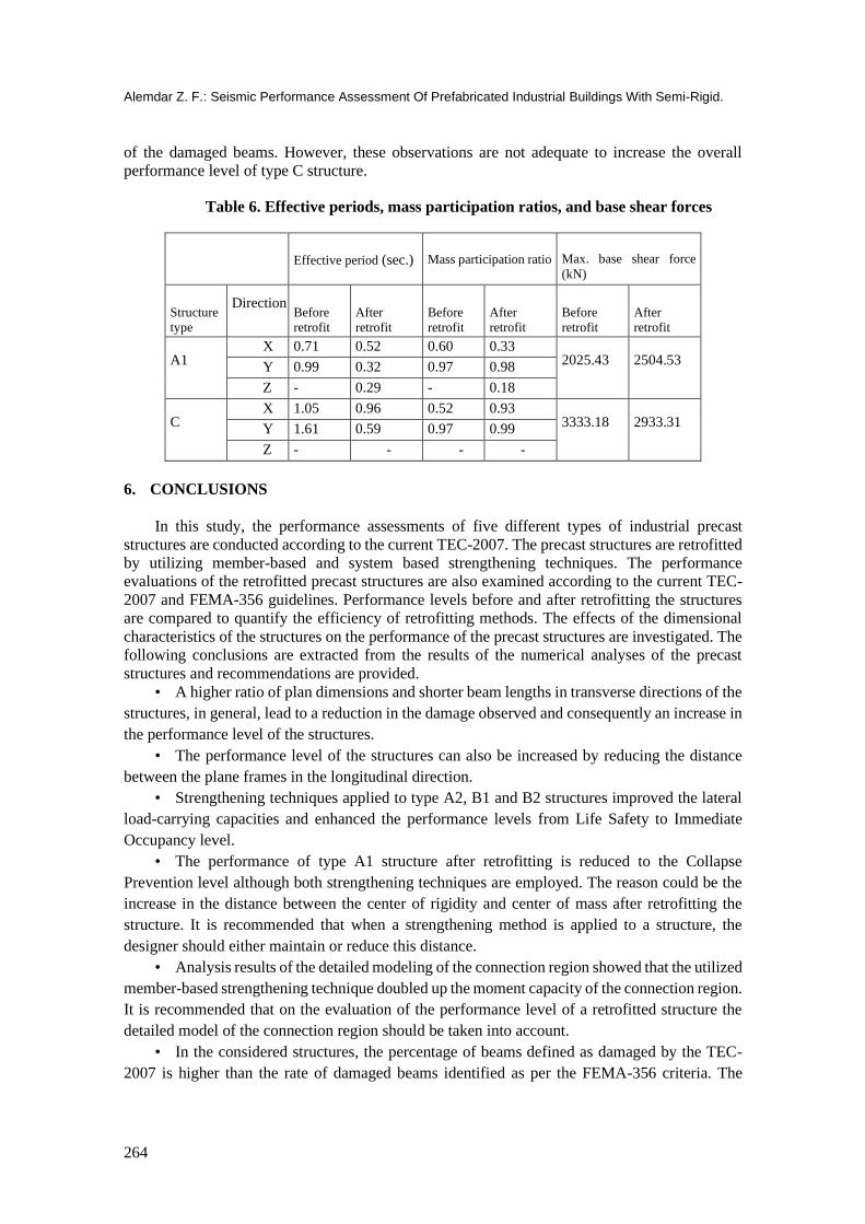
Alemdar Z. F.: Seismic Performance Assessment Of Prefabricated Industrial Buildings With Semi-Rigid.
264
of the damaged beams. However, these observations are not adequate to increase the overall
performance level of type C structure.
Table 6. Effective periods, mass participation ratios, and base shear forces
Effective period (sec.) Mass participation ratio Max. base shear force
(kN)
Structure
type
Direction Before
retrofit
After
retrofit
Before
retrofit
After
retrofit
Before
retrofit
After
retrofit
A1 X 0.71 0.52 0.60 0.33
2025.43 2504.53 Y 0.99 0.32 0.97 0.98
Z - 0.29 - 0.18
C X 1.05 0.96 0.52 0.93
3333.18 2933.31 Y 1.61 0.59 0.97 0.99
Z - - - -
6. CONCLUSIONS
In this study, the performance assessments of five different types of industrial precast
structures are conducted according to the current TEC-2007. The precast structures are retrofitted
by utilizing member-based and system based strengthening techniques. The performance
evaluations of the retrofitted precast structures are also examined according to the current TEC-
2007 and FEMA-356 guidelines. Performance levels before and after retrofitting the structures
are compared to quantify the efficiency of retrofitting methods. The effects of the dimensional
characteristics of the structures on the performance of the precast structures are investigated. The
following conclusions are extracted from the results of the numerical analyses of the precast
structures and recommendations are provided.
• A higher ratio of plan dimensions and shorter beam lengths in transverse directions of the
structures, in general, lead to a reduction in the damage observed and consequently an increase in
the performance level of the structures.
• The performance level of the structures can also be increased by reducing the distance
between the plane frames in the longitudinal direction.
• Strengthening techniques applied to type A2, B1 and B2 structures improved the lateral
load-carrying capacities and enhanced the performance levels from Life Safety to Immediate
Occupancy level.
• The performance of type A1 structure after retrofitting is reduced to the Collapse
Prevention level although both strengthening techniques are employed. The reason could be the
increase in the distance between the center of rigidity and center of mass after retrofitting the
structure. It is recommended that when a strengthening method is applied to a structure, the
designer should either maintain or reduce this distance.
• Analysis results of the detailed modeling of the connection region showed that the utilized
member-based strengthening technique doubled up the moment capacity of the connection region.
It is recommended that on the evaluation of the performance level of a retrofitted structure the
detailed model of the connection region should be taken into account.
• In the considered structures, the percentage of beams defined as damaged by the TEC-
2007 is higher than the rate of damaged beams identified as per the FEMA-356 criteria. The
Uludağ University Journal of The Faculty of Engineering, Vol. 25, No. 1, 2020
265
performance levels determined by the TEC-2007 criteria satisfy the performance levels
requirements given in FEMA-356 guidelines.
REFERENCES
1. ACI-318, (1995). Building code requirements for structural concrete and commentary,
American Concrete Institute, Farmington Hills, MI, USA.
2. Adalier, K. and Aydingun, O. (2001) Structural engineering aspects of the June 27, 1998
Adana-Ceyhan (Turkey) earthquake, Engineering Structures, 23(4), 343-355. doi:
10.1016/S0141-0296(00)00046-8
3. Arslan, M. H., Korkmaz, H. and Gulay, F. G. (2006) Damage and failure pattern of
prefabricated structures after mojor earthquakes in Turkey and shortfalls of the Turkish
Earthquake code, Engineering Failure Analysis, 13(4), 537-557. doi:
10.1016/j.engfailanal.2005.02.006
4. ATC-40, (1996). Seismic Evaluation and Retrofit of Concrete Buildings, Applied Technology
Council, California, USA.
5. Baysal, M. Z. (1991). Behavior of an exterior precast beam-column joint under reversed
cyclic loading, Yüksek Lisans Tezi, O.D.T. Ü. Fen Bilimleri Enstitüsü, Ankara.
6. Belleri, A., Torquati M., Riva, P. and Nascimbene, R. (2015) Vulnerability assessment and
retrofit solutions of precast industrial structures, Earthquakes and Structures, 8(3), 801-820.
doi: 10.12989/eas.2015.8.3.801
7. Bournas, D. A., Negro, P. and Molina, F. J. (2013) Pseudodynamic tests on a full-scale 3-
storey precast concrete buildings: behavior of the mechanical connections and floor
diaphragms, Engineering Structures, 57, 609-627. doi: 10.1016/j.engstruct.2013.05.046
8. Bournas, D. A., Negro, P. and Taucer, F. F. (2014) Performance of industrial buildings during
the Emilia earthquakes in Northern Italy and recommendations for their strengthening,
Bulletin Earthquake Engineering, 12(5), 2383-2404. doi: 10.1007/s10518-013-9466-z
9. BSSC, (2001). NEHRP Recommended Provisions for Seismic Regulations for New
Buildings and Other Structures. Part 1—Provisions, Part 2—Commentary Report Nos.
FEMA-368 and FEMA-369, Building Seismic Safety Council; Federal Emergency
Management Agency, Washington, D.C., USA.
10. Center for Engineering Strong Motion Data, Access Address:
ftp://strongmotioncenter.org/vdc/turkey (Access Data: 07.08.2015)
11. CSI (2018) SAP2000 V-15.1: Structural analysis program, Computers and Structures Inc.,
Berkeley, California.
12. Earthquake Research Department of General Director of Disaster Affairs, Access Address:
http://www.deprem.gov.tr (Access Data: 01.08.2015)
13. EERI (2000) 1999 Kocaeli, Turkey, Earthquake Reconnaissance Report, Earthquake Spectra,
Supplement A to Vol. 16, Earthquake Engineering Research Institute.
14. Elliot, K.S., Davies, G., Gorgun, H. and Adlparvar, M. R. (1998) The stability of precast
concrete skeletal structure, PCI Journal, 43, 42-57.
15. Englekirk, R. E. (2003) Seismic Design of Reinforced and Precast Concrete Buildings, John
Wiley Sons, New York.

Alemdar Z. F.: Seismic Performance Assessment Of Prefabricated Industrial Buildings With Semi-Rigid.
266
16. Ersoy, U. and Tankut, T. (1993) Precast concrete members with welded plate connections
under reversed cyclic loading, PCI Journal, 38(4), 94–100.
17. FEMA-356, (2000). Prestandard and Commentary for Seismic Rehabilitation of Buildings,
Federal Emergency Management Agency, Washington, USA.
18. FEMA-440, (2005). Improvement of Nonlinear Static Seismic Analysis Procedures, Federal
Emergency Management Agency, Washington, USA.
19. Fib Bulletin 27, (2003). Seismic design of precast concrete structures, International
Federation for Structural Concrete, Lausanne, Switzerland.
20. Hibbitt, Karlsson, and Sorensen. (2015) ABAQUS/standard user's manual. HKS Inc., Dallas,
USA.
21. Mander, J. B., Priestley, M. J. and Park, R. (1988) Theoretical stress-strain model for confined
concrete, Journal of Structural Engineering, 114(8), 1804-1826.
22. Negro, P., Bournas, D. and Molina, F. J. (2013) Pseudodynamic tests on a full-scale 3-storey
precast concrete building: global response, Engineering Structures, 57, 596–608. doi:
10.1016/j.engstruct.2013.05.047
23. Nzabonimpa, J. D., Hong, W. K. and Kim J. (2017) Nonlinear finite element model for the
novel mechanical beam-column joints of precast concrete-based frames, Computers and
Structures, 189, 31-48. doi: 10.1016/j.compstruc.2017.04.016
24. Nzabonimpa, J. D., Hong, W. K. and Park, S. C. (2017) Experimental investigation of dry
mechanical beam–column joints for precast concrete based frames, The Structural Design of
Tall and Special Buildings, 26(1). doi: 10.1002/tal.1302
25. Oztug, A, C. (1994). Seismic performance and improvement of an external precast concrete
connection, Yüksek Lisans Tezi, O.D.T. Ü. Fen Bilimleri Enstitüsü, Ankara.
26. Posada, M. and Wood, S.L., 2002, Seismic Performance of Precast Industrial Buildings in
Turkey, Proceedings, 7th U.S. National Conference on Earthquake Engineering, Earthquake
Engineering Research Institute, Boston, MA, Paper 543.
27. Priestley, M.J.N., Sritharan, S., Conley, J. R. and Pampanin, S. (1999) Preliminary results and
conclusions from the PRESS five-story precast concrete test building, PCI Journal, 44, 42-
67.
28. Saatcioglu, M., Mitchell, D., Tinawi, R., Gardner, J., Gillies, A., Ghobarah, A., Anderson, D.
L. and Lau, D. (2001) The August 17, 1999 Kocaeli (Turkey) earthquake-damage to
structures, Canadian Journal of Civil Engineering, 28(4), 715-773. doi: 10.1139/cjce-28-4-
715
29. Sezen, H. and Whittaker, A. S. (2006) Seismic performance of industrial facilities affected
by the 1999 Turkey earthquake, Journal of Performance of Constructed Facilities, 20, 28-39.
doi: 10.1061/(ASCE)0887-3828(2006)20:1(28)
30. TEC, (1998). Specifications for structures to be built in disaster areas, Ministry of Public
Works and Settlement, Ankara, Turkey.
31. TEC, (2007). Specifications for structures to be built in seismic areas, Ministry of Public
Works and Settlement, Ankara, Turkey.
32. TS-498, (1997). Design loads for buildings, Turkish Standards, Ankara, Turkey (in Turkish).
33. Vasconez, R.M., Naaman A. E. and Wight, J. K. (1998) Behavior of HPFRC connections for
precast concrete frames under reversed cyclic loading, PCI Journal, 43, 58-71.

Uludağ University Journal of The Faculty of Engineering, Vol. 25, No. 1, 2020
267
34. Vidjeapriya, R. and Jaya, K. P. (2013) Experimental study on two simple mechanical precast
beam-column connections under reverse cyclic loading, Journal of Performance of
Constructed Facilities, 27(4), 402-414. doi: 10.1061/(ASCE)CF.1943-5509.0000324
35. Wood, S. L. (2003) Seismic Rehabilitation of Low-Rise Precast Industrial Buildings in
Turkey, Advances in Earthquake Engineering for Urban Risk Reduction, Nato Science Series:
IV: Earth and Environmental Sciences, 66, 167-177.
36. XTRACT (2004). Cross-sectional analysis of structural components. Imbsen and Associates
Inc., Sacramento.
37. Xue, W. and Yang, X. (2010) Seismic tests of precast concrete, moment-resisting frames and
connections, PCI Journal, 55, 102-121.
38. Yee P. T. L., Adnan A. B., Mirasa A. K. and Abdul Rahman, A. B. (2011) Performance of
IBS precast concrete beam-column connections under earthquake effects: A literature review,
American Journal of Engineering and Applied Sciences, 4(1), 93-101. doi:
10.3844/ajeassp.2011.93.101
39. Yuksel, E., Karadogan, H. F., Bal, İ. E., Ilki, A., Bal, A., and Inci, P. (2015) Seismic behavior
of two exterior beam-column connections made of normal-strength concrete developed for
precast construction, Engineering Structures, 99, 157–172. doi:
10.1016/j.engstruct.2015.04.044

268